WO2012077772A1 - Image blur correction unit, image blur correction device, and optical apparatus - Google Patents
Image blur correction unit, image blur correction device, and optical apparatus Download PDFInfo
- Publication number
- WO2012077772A1 WO2012077772A1 PCT/JP2011/078497 JP2011078497W WO2012077772A1 WO 2012077772 A1 WO2012077772 A1 WO 2012077772A1 JP 2011078497 W JP2011078497 W JP 2011078497W WO 2012077772 A1 WO2012077772 A1 WO 2012077772A1
- Authority
- WO
- WIPO (PCT)
- Prior art keywords
- image blur
- blur correction
- central axis
- support portions
- prism
- Prior art date
Links
Images

Classifications
-
- G—PHYSICS
- G03—PHOTOGRAPHY; CINEMATOGRAPHY; ANALOGOUS TECHNIQUES USING WAVES OTHER THAN OPTICAL WAVES; ELECTROGRAPHY; HOLOGRAPHY
- G03B—APPARATUS OR ARRANGEMENTS FOR TAKING PHOTOGRAPHS OR FOR PROJECTING OR VIEWING THEM; APPARATUS OR ARRANGEMENTS EMPLOYING ANALOGOUS TECHNIQUES USING WAVES OTHER THAN OPTICAL WAVES; ACCESSORIES THEREFOR
- G03B5/00—Adjustment of optical system relative to image or object surface other than for focusing
- G03B5/06—Swinging lens about normal to the optical axis
-
- G—PHYSICS
- G03—PHOTOGRAPHY; CINEMATOGRAPHY; ANALOGOUS TECHNIQUES USING WAVES OTHER THAN OPTICAL WAVES; ELECTROGRAPHY; HOLOGRAPHY
- G03B—APPARATUS OR ARRANGEMENTS FOR TAKING PHOTOGRAPHS OR FOR PROJECTING OR VIEWING THEM; APPARATUS OR ARRANGEMENTS EMPLOYING ANALOGOUS TECHNIQUES USING WAVES OTHER THAN OPTICAL WAVES; ACCESSORIES THEREFOR
- G03B5/00—Adjustment of optical system relative to image or object surface other than for focusing
-
- H—ELECTRICITY
- H04—ELECTRIC COMMUNICATION TECHNIQUE
- H04N—PICTORIAL COMMUNICATION, e.g. TELEVISION
- H04N23/00—Cameras or camera modules comprising electronic image sensors; Control thereof
- H04N23/50—Constructional details
- H04N23/55—Optical parts specially adapted for electronic image sensors; Mounting thereof
-
- H—ELECTRICITY
- H04—ELECTRIC COMMUNICATION TECHNIQUE
- H04N—PICTORIAL COMMUNICATION, e.g. TELEVISION
- H04N23/00—Cameras or camera modules comprising electronic image sensors; Control thereof
- H04N23/60—Control of cameras or camera modules
- H04N23/68—Control of cameras or camera modules for stable pick-up of the scene, e.g. compensating for camera body vibrations
- H04N23/682—Vibration or motion blur correction
- H04N23/685—Vibration or motion blur correction performed by mechanical compensation
- H04N23/686—Vibration or motion blur correction performed by mechanical compensation with a variable apex prism
-
- H—ELECTRICITY
- H04—ELECTRIC COMMUNICATION TECHNIQUE
- H04N—PICTORIAL COMMUNICATION, e.g. TELEVISION
- H04N23/00—Cameras or camera modules comprising electronic image sensors; Control thereof
- H04N23/60—Control of cameras or camera modules
- H04N23/68—Control of cameras or camera modules for stable pick-up of the scene, e.g. compensating for camera body vibrations
- H04N23/682—Vibration or motion blur correction
- H04N23/685—Vibration or motion blur correction performed by mechanical compensation
- H04N23/687—Vibration or motion blur correction performed by mechanical compensation by shifting the lens or sensor position
Definitions
- the present invention relates to an image blur correction unit, an image blur correction device, and an optical device, and is suitable for application to, for example, correcting camera shake of a camera such as a digital camera.
- the camera shake correction function for a camera is generally an optical type that physically adjusts the optical axis
- the optical camera shake correction function is typically a lens shift type and an image sensor shift type.
- the lens shift type camera shake correction function corrects the optical axis by moving part or all of the lens group that forms a subject image on the image sensor in a direction that cancels camera shake using a dedicated drive mechanism, thereby correcting the optical axis.
- the subject image is guided to the image (see, for example, Patent Document 1).
- the image sensor shift type camera shake correction function keeps the position of the image sensor with respect to the optical axis of the lens group constant by moving the image sensor in accordance with the camera shake with a dedicated drive mechanism (see, for example, Patent Document 2).
- a dedicated drive mechanism must be designed for each image sensor different for each camera. Therefore, a correction attachment having a movable prism that refracts light incident on the optical lens, a motor for driving the movable prism, and a shaft for transmitting the power of the motor to the movable prism is provided in the optical lens.
- a correction attachment having a movable prism that refracts light incident on the optical lens, a motor for driving the movable prism, and a shaft for transmitting the power of the motor to the movable prism is provided in the optical lens.
- Patent Document 3 There has been proposed one that is mounted on the optical axis. Thereby, it becomes unnecessary to design the shape of the correction lens and the drive mechanism for each camera, and the design can be simplified
- the present invention has been made in view of the above points, and intends to propose an image blur correction unit, an image blur correction device, and an optical device that can be miniaturized.
- an image blur correction unit which is a first and second refracting element that refracts light transmitted through an optical lens and guided to an image sensor, and first and second The first and second refracting elements are respectively supported on the outer peripheral side of the refracting element so that the first and second refracting elements can be rotated within 180 degrees about the central axis serving as the rotation center of the first and second refracting elements. And first and second support portions.
- an image blur correction apparatus that detects and corrects camera shake, and transmits the camera shake detection unit that detects camera shake and an optical lens provided in the camera.
- the first and second refracting elements that refract the light guided to the image sensor and the outer peripheral sides of the first and second refracting elements, and the rotation centers of the first and second refracting elements,
- the first and second support portions that rotatably support the first and second refracting elements, respectively, within 180 degrees about the central axis, and the camera shake detected by the detection portion
- a drive unit that rotationally drives the first and second support units.
- First and second support portions that respectively support the first and second refracting elements so as to be rotatable within 180 degrees about the central axis that is the center of rotation of the element.
- the first and second support portions do not support the first and second refractive elements along the circumferential direction, but rotate within a range of 180 degrees with respect to the rotation center of each refractive element. Since it is supported so that it can move, the range which supports the 1st and 2nd refractive element in the plane orthogonal to a rotation center can be narrowed.
- the first and second support portions are not supported along the circumferential direction of the first and second refractive elements, but are each within a range of 180 degrees around the central axis. Therefore, the range in which the first and second refractive elements are supported on a plane orthogonal to the central axis can be narrowed, and thus the size can be reduced.
- FIG. 1 is a schematic diagram illustrating an optical configuration of a camera.
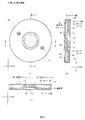
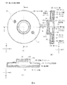
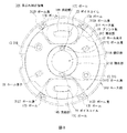
- 2A shows the configuration of the image blur correction mechanism
- FIG. 2B shows the AA ′ section of FIG. 2A
- FIG. 2C shows the BB ′ section of FIG.
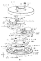
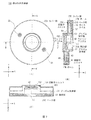
- FIG. 3 is an exploded perspective view of the image blur correction mechanism.
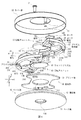
- FIG. 4 is an exploded perspective view of the image blur correction mechanism.
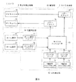
- FIG. 5 is a schematic diagram illustrating a circuit configuration of the camera. 6A shows a configuration of an image blur correction mechanism according to another embodiment, FIG. 6B shows a cross section taken along the line AA ′ in FIG. 6A, and FIG. 6C shows a cross section taken along the line BB ′ in FIG. It is.
- FIG. 7A shows a configuration of an image blur correction mechanism according to another embodiment
- FIG. 7B shows a cross section taken along the line AA ′ in FIG. 7A
- FIG. 7C shows a cross section taken along the line BB ′ in FIG. It is.
- FIG. 8 is a schematic diagram illustrating a configuration of an image blur correction mechanism according to another embodiment.
- FIG. 1 shows a camera 1 according to the present embodiment.
- the camera 1 includes a camera body 2 and a lens barrel 3 that is detachably attached to the camera body 2.
- the camera body 2 is provided with an imaging element 4 on which a subject image is formed, such as a charge coupled device sensor (CCD) and a complementary metal oxide semiconductor (CMOS).
- CMOS complementary metal oxide semiconductor
- the lens barrel 3 moves the subject image in the horizontal direction (X-axis direction) and the vertical direction (Y-axis direction) with respect to the lens group 5 including a plurality of lenses 5A to 5E and the optical axis L1 of the lens group 5.
- An image blur correction mechanism 6 is provided.
- the image blur correction mechanism 6 is disposed, for example, between the lenses 5D and 5E in which the light beam transmitted through the lens group 5 on the optical axis L1 becomes narrow.
- the lens group 5 is adjusted in zoom and focus by moving in the direction of the optical axis L1.
- the imaging element 4 converts the subject image formed through the lens group 5 and the image blur correction mechanism 6 into an electrical signal.
- image data is obtained by A / D converting the electrical signal.
- the direction along the optical axis L1 of the lens group 5 is the Z-axis direction
- the horizontal direction orthogonal to the Z-axis direction is the X-axis direction
- the Z-axis direction is A description will be given assuming that the orthogonal vertical direction is the Y axis direction.
- the image blur correction mechanism 6 is formed in a flat, substantially cylindrical shape having a diameter of 30 mm and a thickness of 5 mm, for example, and its central axis L2 and the optical axis L1 of the lens group 5 coincide with each other. In this manner, the lens barrel 3 is arranged.
- the central axis L2 is the rotation center of wedge prisms 42 and 52, which will be described later, and does not have to coincide with the optical axis L1.
- the image blur correction mechanism 6 includes a substrate portion 30 and rotor units 40 and 50 in a space formed by covering a cup-shaped cover portion 20 made of resin or the like with a substantially circular flat base portion 10 made of resin or the like. Arranged.
- a base plate 11, an annular portion 12, a screw hole strut portion 13, and a protruding portion 14 are integrally formed of resin or the like.
- the base plate 11 has a substantially circular flat plate shape, and is provided with an opening 11A larger than the luminous flux of the subject image transmitted through the lens group 5 with the central axis L2 as the center.
- the annular portion 12 is inward from the outer edge of the surface of the base plate 11 on the cover portion 20 side by the thickness of the cover portion 20, more specifically than the width of ball grooves 12A to 12F for rolling balls 17A to 17F described later. It is formed in a ring shape having a slightly longer width and higher than the thickness of the printed board 31.
- the screw hole strut portion 13 is formed in a cylindrical shape provided with screw grooves 13A and 13B on the inner side, and is located at a predetermined position inside the annular portion 12 on the surface on the cover portion 20 side of the base plate 11 and with the central axis L2. They are provided at positions symmetrical to each other as a reference.
- the base plate 11 is provided with voice coils 15 and 16 and yokes 18 and 19 that are thinner than the height of the annular portion 12 inside the annular portion 12 on the surface on the cover portion 20 side.
- Each of the voice coils 15 and 16 is located on a vertical line (Y axis) perpendicular to the central axis L2 and is symmetric with respect to the central axis L2, and is substantially parallel to the surface of the base plate 11. It is formed in a substantially fan shape around which an electric wire is wound.
- the yokes 18 and 19 are formed in substantially the same shape as the voice coils 15 and 16.
- the base plate 11 is lower in height than the overlapping of the yokes 18 and 19 and the voice coils 15 and 16 inside the annular portion 12 on the surface on the cover portion 20 side, and the outer peripheral shape thereof is the voice coils 15 and 16 and the yoke 18.
- the ball grooves 12A to 12F formed in the annular portion 12 are provided such that the ball grooves 12A and 12D are symmetric with respect to the center of the base plate 11, and the ball grooves 12B and 12E and the ball grooves 12C and 12F are also bases, respectively. They are provided at symmetrical positions with respect to the center of the plate 11.
- the ball grooves 12A and 12D are provided on a center line (Y axis) passing through the centers of the voice coils 15 and 16.
- the ball grooves 12B and 12C are symmetrical with respect to the Y axis on the ball groove 12A side (Y axis negative direction side) with respect to the central axis L2 in the annular portion 12, and the center of the voice coil 15 is the ball grooves 12A, 12B and It is provided so as to be located within a triangle connecting the centers of 12C.
- the ball grooves 12E and 12F are symmetrical with respect to the Y axis on the ball groove 12D side (Y axis positive direction side) with respect to the center axis L2 of the annular portion 12, and the winding center of the voice coil 16 is the ball groove. It is provided so as to be located within a triangle connecting the centers of 12D, 12E and 12F.
- the cover 20 is provided with a circular opening 20A that is larger than the luminous flux of the subject image transmitted by the lens group 5 with the central axis L2 as the center.
- the cover portion 20 is provided with holes 20B and 20C through which the screws 21 and 22 are inserted at positions facing the screw hole strut portion 13 of the base portion 10.
- the substrate unit 30 includes a printed board 31 and hall elements 32 and 33.
- the printed board 31 is formed in a flat, substantially circular shape having substantially the same diameter as the inner diameter of the annular portion 12 from which only portions corresponding to the voice coils 15 and 16 are removed so as to be in close contact with the inside of the annular portion 12 in the base plate 11. Is done.
- the printed board 31 is provided with an opening 31A slightly larger than the opening 11A at a position corresponding to the opening 11A of the base plate 11.
- the printed board 31 is provided with holes 31B and 31C through which the two screw hole struts 13 of the base 10 are respectively inserted.
- the hall elements 32 and 33 are provided at positions symmetrical to each other with respect to the central axis L2 in the vicinity of the voice coils 15 and 16, respectively.
- the rotor unit 40 includes a prism support portion 41 and a wedge prism 42, a magnet 43, a yoke 44, a magnet 45, and a yoke 46, which are integrally formed of, for example, a transparent acrylic resin.
- the prism support portion 41 has a central angle smaller than 180 degrees with the central axis L2 as the center, and the outer edge radius thereof is the same radius as the outer edge radius of the annular portion 12 of the base portion 10, and the wedge prism 42 is centered on the central axis L2. This is formed into a flat fan shape with a notched (recessed) portion.
- the prism support portion 41 is a hole portion that is fitted to the outer edge shape of the magnet 43 and the yoke 44 so that the magnet 43 and the yoke 44 are fitted to a position facing the voice coil 15 on a center line that bisects the central angle. 41A is provided.
- the magnet 43 has a slightly smaller outer shape in the surface direction than the yoke 44.
- the hole 41A is formed according to the outer edge shape of the magnet 43 and the yoke 44, thereby forming a step 41A1 in which the size of the hole decreases in the Z-axis direction.
- the prism support portion 41 is provided with a hole portion 41B that is fitted to the outer edge shape of the magnet 45 and the yoke 46 so that the magnet 45 and the yoke 46 are fitted at a position facing the hall element 32.
- the outer shape of the magnet 45 in the surface direction is slightly smaller than that of the yoke 46.
- the hole 41B is formed according to the outer edge shape of the magnet 45 and the yoke 46, thereby forming a step 41B1 in which the size of the hole decreases in the Z-axis direction.
- the prism support portion 41 is provided with a hole 41C at a position facing the screw hole strut portion 13 provided with the screw groove 13A.
- the hole portion 41C is brought into contact with the screw hole strut portion 13 provided with the screw groove 13A and the prism support portion 41, so that the rotor unit 40 and 50 is formed in such a size that it does not contact each other even when both ends of the prism support portions 41 and 51 are rotated in the direction in which they approach each other.
- the prism support portion 41 is provided with ball grooves 41D, 41E, and 41F having a substantially triangular cross section at a position facing the ball grooves 12A, 12B, and 12C of the base portion 10 on the surface facing the base portion 10. That is, the prism support portion 41 rotates in a range of 180 degrees or less on a plane centering on the central axis L2.
- the wedge prism 42 is thinner than half of the thickness of the thick part 41G formed to be thick in order to support the wedge prism 42 in the prism support part 41, and from the center in the thickness direction of the thick part 41G.
- the wedge prism 42 has a substantially circular flat plate shape centered on the central axis L2, and its both surfaces are inclined toward each other in the positive direction of the Y axis with respect to the XY plane (surface perpendicular to the central axis L2). have. That is, the wedge prism 42 is inclined with respect to the XY plane so that the prism support portion 41 side (Y-axis negative direction side) is thick and the opposite side (Y-axis positive direction side) is thin.
- the rotor unit 50 includes a prism support 51 and a wedge prism 52, a magnet 53, a yoke 54, a magnet 55, and a yoke 56, which are integrally formed of, for example, a transparent acrylic resin.
- the prism support portion 51 has a central angle smaller than 180 degrees with respect to the central axis L2, the outer edge radius thereof is the same as the outer edge radius of the annular portion 12 of the base portion 10, and the wedge prism 52 with the central axis L2 as the center. This is formed into a flat fan shape with a notched (recessed) portion.
- the prism support portion 51 has a hole portion that is fitted to the outer edge shape of the magnet 53 and the yoke 54 so that the magnet 53 and the yoke 54 are fitted to a position facing the voice coil 16 on the center line that bisects the central angle. 51A is provided.
- the magnet 53 has a slightly smaller outer shape in the plane direction than the yoke 54.
- the hole 51A is formed according to the outer edge shape of the magnet 53 and the yoke 54, thereby forming a step 51A1 in which the hole size decreases in the Z-axis direction.
- the prism support portion 51 is provided with a hole portion 51 ⁇ / b> B fitted to the outer edge shape of the magnet 55 and the yoke 56 so that the magnet 55 and the yoke 56 are fitted in a position facing the hall element 33.
- the magnet 53 has a slightly smaller outer shape in the plane direction than the yoke 54.
- the hole 51B is formed according to the outer edge shape of the magnet 55 and the yoke 56, thereby forming a step 51B1 in which the size of the hole decreases in the Z-axis direction.
- the prism support portion 51 is provided with a hole portion 51C at a position facing the screw hole strut portion 13 provided with the screw groove 13B.
- the hole 51C is brought into contact with the screw support column portion 13 provided with the screw groove 13B and the prism support portion 51, so that the rotor unit 40 and 50 is formed in such a size that it does not contact each other even when both ends of the prism support portions 41 and 51 are rotated in the direction in which they approach each other.
- the prism support portion 51 is provided with ball grooves 51D, 51E, and 51F having a substantially triangular cross section at a position facing the ball grooves 12D, 12E, and 12F of the base portion 10 on a surface facing the base portion 10.
- the wedge prism 52 is thinner than half of the thickness of the thick part 51G formed to be thick in order to support the wedge prism 52 in the prism support part 51, and from the center in the thickness direction of the thick part 51G. Also, it is integrally formed with the prism support portion 51 so that all of them are located on the cover portion 20 side (Z-axis negative direction side).
- the thick part 51G is formed to have the same thickness in the Z-axis direction as the thick part 41G.
- the thick portions 41G and 51G may have the same thickness as other portions as long as the wedge prisms 42 and 52 can be supported within the thickness of the prism support portions 41 and 51 in the Z-axis direction.
- the wedge prism 52 has a substantially circular flat plate shape centered on the central axis L2, and its both surfaces are inclined toward each other in the negative direction of the X axis with reference to the XY plane (surface perpendicular to the central axis L2). have. That is, the wedge prism 52 is inclined with respect to the XY plane so that the X-axis positive direction side is thick and the opposite side (X-axis negative direction side) is thin.
- the substrate part 30 is located inside the annular part 12 of the base plate 11 of the base part 10, and the outside of the protruding part 14 of the base plate 11.
- the voice coils 15 and 16 and the yokes 18 and 19 are fitted, for example, by bonding.
- the magnet 43 and the yoke 44 are disposed in the hole portion 41 ⁇ / b> A of the prism support portion 41
- the magnet 45 and the yoke 46 are disposed in the hole portion 41 ⁇ / b> B of the prism support portion 41.
- the rotor unit 40 is supported by the base portion 10 at a predetermined interval so that the ball grooves 41D to 41F in the prism support portion 41 and the ball grooves 12A to 12C in the base portion 10 sandwich the balls 17A to 17C. .
- a position where a center line that bisects the center angle of the prism support portion 41 and a vertical direction (Y axis) orthogonal to the center axis L2 coincide is set as a reference position.
- the rotor unit 40 is only supported by the balls 17A to 17C at three points, only the ball grooves 41D to 41F and the balls 17A to 17C are in contact with each other.
- the rotor unit 40 can be rotated by a predetermined angle from the center axis L2 to the left and right with the Y axis as a reference.
- the wedge prism 42 refracts light that is transmitted through the lens group 5 and moves along the substantially Y axis according to the rotation angle.
- the prism support portion 51 rotates to the left or right and the screw hole strut portion 13 provided with the screw groove 13A and the hole portion 41C of the prism support portion 41 are in contact with each other.
- the size of the balls 17A to 17C is determined so that the balls 17A to 17C do not contact both ends of the ball groove. Further, the rotor unit 40 is always attracted in the direction of the base portion 10 (Z-axis positive direction) by the attracting force with which the magnet 43 is attracted to the yoke 18, so that the rotor unit 40 does not leave the base portion 10. Supported by the base portion 10. At this time, in the prism support portion 41, the magnet 43 and the yoke 44 are in close contact with each other by magnetic force, and the magnet 43 and the yoke 44 are not detached from the prism support portion 41 when the outer edge portion of the yoke 44 is caught by the step 41A1. .
- the magnet 45 and the yoke 46 are in close contact with each other by magnetic force, and the magnet 45 and the yoke 46 are not detached from the prism support portion 41 when the outer edge portion of the yoke 46 is caught on the step 41B1. It is held at a position facing the element 32.
- the magnet 53 and the yoke 54 are disposed in the hole 51 ⁇ / b> A of the prism support 51, and the magnet 55 and the yoke 56 are disposed in the hole 51 ⁇ / b> B of the prism support 51.
- the rotor unit 50 is supported at a predetermined distance from the base portion 10 so that the ball grooves 51D to 51F in the prism support portion 51 and the ball grooves 12D to 12F in the base portion 10 sandwich the balls 17D to 17F. .
- a position where a center line that bisects the center angle of the prism support portion 51 and a vertical direction (Y axis) orthogonal to the center axis L2 coincide is set as a reference position.
- the ball grooves 51D to 51F and the balls 17D to 17F are only in contact with each other, and are supported at three points by the balls 17D to 17F.
- the rotor unit 50 can be rotated by a predetermined angle from the center axis L2 to the left and right with the Y axis as a reference. Accordingly, the prism support portions 41 and 51 are supported by the base portion 10 on the same XY plane orthogonal to the central axis L2 and rotate.
- the wedge prism 52 refracts light that is transmitted through the lens group 5 and moves along the X axis according to the rotation angle.
- the prism support part 51 rotates to the left or right and the screw hole support part 13 provided with the screw groove 13B and the hole part 51C of the prism support part 51 are in contact with each other.
- the size of the balls 17D to 17F is determined so that the balls 17D to 17F do not contact both ends of the ball groove.
- the rotor unit 50 is always attracted in the direction of the base portion 10 (Z-axis positive direction) by the attracting force with which the magnet 53 is attracted to the yoke 19, so that the rotor unit 50 does not leave the base portion 10. Supported by the base portion 10.
- the magnet 53 and the yoke 54 are in close contact with each other by magnetic force, and the magnet 53 and the yoke 54 are not detached from the prism support portion 51 when the outer edge portion of the yoke 54 is caught by the step 51A1. .
- the magnet 55 and the yoke 56 are in close contact with each other by magnetic force, and the magnet 55 and the yoke 56 are not detached from the prism support portion 51 when the outer edge portion of the yoke 56 is caught on the step 51B1. It is held at a position facing the element 33.
- the cover part 20 covers the screws 21 and 22 in the screw grooves 13 ⁇ / b> A and 13 ⁇ / b> B of the screw hole strut part 13. Screwed to stop.
- the wedge prism 42 is thinner than half of the thickness of the thick portion 41G, and all of the wedge prisms 42 are located on the Z axis positive direction side of the center in the thickness direction of the thick portion 41G. It is formed.
- the wedge prism 52 is formed so as to be thinner than half of the thickness of the thick part 51G and to be positioned on the Z-axis negative direction side from the center in the thickness direction of the thick part 51G.
- the wedge prisms 42 and 52 are supported so as to face the space formed by the prism support portions 41 and 51 being adjacent to each other. It can be rotated around the center axis L2 (optical axis L1) without contact.
- the camera 1 includes positions of a microcomputer 61 that controls the whole, a shake detection unit 62 that detects a shake of the camera 1, a drive unit 63 that rotationally drives the rotor units 40 and 50, and the rotation element units 40 and 50.
- a position detection unit 64 for detection is provided.
- the camera body 2 is provided with a microcomputer 61, an X-axis direction gyro sensor 71, a Y-axis direction gyro sensor 72, gyro amplifiers 73 and 74, power drivers 75 and 76, and hall element drivers 77 and 78.
- the image blur correction mechanism 6 is provided with voice coils 15 and 16 and hall elements 32 and 33.
- the microcomputer 61 has a computer configuration including a CPU (Central Processing Unit), a ROM (Read Only Memory), a RAM (Random Access memory), and the like.
- the microcomputer 61 performs overall control by developing and executing the basic program stored in the ROM in the RAM, and executes various processes by developing and executing the various programs stored in the ROM in the RAM. To do.
- the X-axis direction gyro sensor 71 detects an angular velocity of the camera 1 in the X-axis direction, that is, a shake in the X-axis direction as an angular velocity signal.
- the Y-axis direction gyro sensor 72 detects the angular velocity of the camera 1 in the Y-axis direction, that is, shake in the Y-axis direction as an angular velocity signal.
- the gyro amplifiers 73 and 74 amplify the angular velocity signals detected by the X-axis direction gyro sensor 71 and the Y-axis direction gyro sensor 72, respectively, and send them to the microcomputer 61.
- the power drivers 75 and 76 apply current to the voice coils 15 and 16 according to the control of the microcomputer 61.
- the hall elements 32 and 33 are arranged at positions facing the magnets 45 and 55 arranged on the prism support portions 41 and 51, respectively.
- the magnets 45 and 55 that change by the rotational movement of the rotor units 40 and 50 are provided. A change in the generated magnetic field is detected as a magnetic field signal.
- the hall element drivers 77 and 78 amplify the magnetic field signals detected by the hall elements 32 and 33 and send them to the microcomputer 61.
- the microcomputer 61 detects the amount of shake of the camera 1 in the X-axis direction and the Y-axis direction based on the angular velocity signals detected by the X-axis direction gyro sensor 71 and the Y-axis direction gyro sensor 72 and supplied via the gyro amplifiers 73 and 74. Is calculated.
- the microcomputer 61 calculates a movement amount for moving the image formed on the image sensor 4 in the X-axis direction and the Y-axis direction in order to correct the calculated blur amount of the camera 1 in the X-axis direction and the Y-axis direction. .
- the microcomputer 61 calculates an angle for rotating the rotor units 40 and 50 so that the image moves to the calculated movement amount, and sets the power drivers 75 and 76 so that the rotor units 40 and 50 move to the angle.
- a current is applied to the voice coils 15 and 16 under control.
- the microcomputer 61 detects the shake amount of the camera 1 in the X-axis direction and the Y-axis direction, the microcomputer 61 rotates and moves the rotor unit 40 according to the shake amount in the Y-axis direction. Is rotated according to the amount of shake in the X-axis direction, thereby moving the light transmitted through the lens group 5 according to the amount of shake.
- the microcomputer 61 acquires the magnetic field signals detected by the Hall elements 32 and 33 and supplied via the Hall element drivers 34 and 35 at predetermined intervals, and the rotation of the rotor units 40 and 50 based on the magnetic field signals. Calculate speed and rotation angle.
- the microcomputer 61 performs feedback control until the rotation angles of the rotor units 40 and 50 calculated at predetermined intervals are moved to an angle that must be moved to correct the shake amount. Thereby, the camera 1 can correct the shake generated in the camera 1 by controlling the rotation of the rotor units 40 and 50 of the image shake correction mechanism 6.
- the image blur correction mechanism 6 has the wedge prisms 42 and 52 that refract the light transmitted through the lens group 5 and guided to the imaging device 4 on the same plane orthogonal to the central axis L2 (optical axis L1).
- the prism support portions 41 and 51 that are arranged and turnable are respectively supported.
- the prism support 41 is centered so that the wedge prisms 42 and 52 face each other at a predetermined distance along the central axis L2 in the space formed when the prism support 41 and 51 are arranged adjacent to each other.
- the wedge prism 42 is supported on one end side (Z-axis positive direction side) along the axis L2, and the prism support portion 51 supports the wedge prism 52 on one end side (Z-axis negative direction side) along the central axis L2.
- the prism support portions 41 and 52 are arranged on the same plane.
- the prism support portions 41 and 51 can be reduced in size because the thickness in the direction of the central axis L2 can be reduced as compared with the case where the prism support portions 41 and 51 are arranged at a predetermined interval along the central axis L2.
- the image blur correcting mechanism 6 includes the voice coils 15 and 16 and the yokes 18 and 19 arranged on the surface of the base portion 10 that supports the prism support portions 41 and 52 on a surface orthogonal to the central axis L2, and the prism support. Magnets 43 and 53 are arranged at positions facing the voice coils 15 and 16 in the portions 41 and 51, respectively.
- the image blur correction mechanism 6 rotates the prism support portions 41 and 51 by electromagnetic force generated between the magnets 43 and 53 when a current is applied to the voice coils 15 and 16.
- the image blur correction mechanism 6 need only have a mechanism for rotating the wedge prisms 42 and 52 only on one surface of the base portion 10, and can be reduced in size accordingly.
- the image blur correction mechanism 6 presses the prism support portions 41 and 51 against the base portion 10 by the attraction force generated between the yoke 18 and the magnet 43 and between the yoke 19 and the magnet 53. It is not necessary to separately provide a device for holding the unit 10 so as to be supported, and the size can be reduced accordingly.
- the image blur correcting mechanism 6 is supported at three points by balls 17A to 17C and 17D to 17F on which prism support portions 41 and 51 are arranged on the same plane, and magnets 43 and 53 provided on the prism support portions 41 and 51, respectively. Since the rotor unit 40 and 50 can be stably supported without providing another device, the size of the rotor can be reduced accordingly. it can. According to the above configuration, the wedge prisms 42 and 52 that refract the light that is transmitted through the lens group 5 and guided to the imaging device 4 are arranged on the same plane orthogonal to the central axis L2, and can be rotated.
- the prism support portion 41 is opposed to the central axis L2 so that the wedge prisms 42 and 51 are opposed to each other at a predetermined distance along the central axis L2 in the space formed when they are supported adjacent to each other and arranged adjacent to each other.
- the wedge prism 42 is supported on one end side along the axis, and the prism support portion 51 is arranged so as to be opposed to each other at a predetermined interval along the center axis L2 by supporting the wedge prism 52 on the other end side along the center axis L2. Since the prism support portions 41 and 51 that support the wedge prisms 42 and 52 that must be provided are arranged on the same plane, the thickness in the optical axis direction is reduced. It can, thus can be miniaturized. [5.
- the wedge prisms 42 and 52 having the above have been described.
- the present invention is not limited to this.
- a diffraction grating or the like may be used as long as the light that passes through the lens group 5 and is applied to the imaging device 4 is moved in the X-axis direction and the Y-axis direction.
- the case where the image blur correction mechanism 6 is provided between the lenses 5D and 5E has been described.
- the present invention is not limited to this, and the front of the lens group 5 (what is the imaging device 4)? It may be provided on the opposite side), may be provided immediately before the image sensor 4, or may be provided at any position between the lenses of the lens group 5.
- the image blur correction mechanism 6 may be provided in the camera body 2.
- the case where the voice coils 15 and 16 are provided in the base portion 10 and the magnets 43 and 53 are provided in the prism support portions 41 and 51 has been described.
- the present invention is not limited to this, and a magnet may be provided on the base portion 10 and a voice coil may be provided on the prism support portions 41 and 51.
- the case where the wedge prisms 42 and 52 are integrally formed with the prism support portions 41 and 51 by resin or the like has been described.
- the present invention is not limited to this, and instead of one or both of the wedge prisms 42 and 52, a wedge prism made of glass is bonded to one or both sides of a parallel prism integrally formed with the prism support portions 41 and 51 using, for example, resin.
- the incident light can be moved in the substantially X-axis and Y-axis directions in accordance with the rotation of the rotor unit.
- the prism support that supports the wedge prism on the outer peripheral side thereof.
- the central portion is formed in a shape with a central angle smaller than 180 degrees around the central axis, and a magnet or yoke is provided in the prism support portion to support the wedge prism so as to be rotatable about the central axis.
- the pair of rotor units may be arranged on different planes.
- the image blur correction mechanism 106 is provided with rotor units 140 and 150 as shown in FIG. 6 in which parts corresponding to those in FIGS.
- wedge prisms 142 and 152 are provided away from the base portion 10 in the negative Z-axis direction.
- the cover 120 is formed in a shape that matches the rotor units 140 and 150.
- the prism support portions 141 and 151 are formed in a fan shape having a central angle smaller than 180 degrees with the central axis L2 as a center, and rotate on the same plane with respect to the base portion 10 via the balls 17A to C and 17D to 17F. Arranged freely.
- the prism support portions 141 and 151 have thicker portions 141G and 151G for supporting the wedge prisms 142 and 152 on the Z axis negative direction side (opposite to the base portion 10). (Direction side) is formed thick.
- the prism support portions 141 and 151 support the wedge prisms 142 and 152 so as to face each other so that their inclinations are shifted by 90 degrees on the Z axis negative direction side in the thick portions 141G and 151G formed to be thick.
- the image blur correction mechanism 106 is provided with the wedge prisms 142 and 152 spaced apart on the Z axis negative direction side with respect to the surface on which the prism support portions 141 and 151 are disposed.
- a space where nothing is provided is formed from the opening portion 11 ⁇ / b> A of the base portion 10 to the wedge prism 142. Therefore, the image blur correction mechanism 106 is particularly effective when the prism support portions 141 and 151 and the wedge prisms 142 and 152 cannot be arranged on the same plane due to the arrangement of each part of the camera, the lens group, and the like.
- the image blur correction mechanism 206 is provided with rotor units 40 and 150.
- the wedge prisms 42 and 152 are arranged to face each other, but the prism support portions 41 and 151 are arranged on different planes.
- the base portion 210 Since the base portion 210 supports the prism support portions 41 and 151 on different surfaces in the Z-axis direction, the base portion 210 has surfaces with different heights in the vertical direction (Y-axis direction) with respect to the central axis L2. Thus, the prism support portions 41 and 151 are rotatably supported via the balls 17A to C and 17D to 17F.
- the cover unit 220 is formed in a shape that matches the rotor units 40 and 150. This image blur correction mechanism 206 is particularly effective when the prism support portion 41 and the prism support portion 151 cannot be arranged on the same plane due to the arrangement of each part of the camera, the lens group, and the like.
- the image blur correction mechanism 206 can be provided with, for example, another lens in a space where nothing is provided from the opening 211A of the base 210 to the wedge prism 42, so that the entire apparatus can be reduced in size.
- the rotor units 40 and 50 are supported at three points by the balls 17A to 17C and 17D to 17F arranged concentrically has been described.
- the present invention is not limited to this, and the balls are arranged in the same circle as long as the centers of the magnets 43 and 52 arranged on the prism support portions 41 and 51 are located within a triangle connecting the three supported points. There is no need to For example, as shown in FIG. 8 in which parts corresponding to those in FIGS.
- the image blur correction mechanism 306 has a ball groove in an annular portion 312 provided in the vicinity of the outer edge of the base plate 311 in the base portion 310.
- 312A to 312D are provided concentrically around the central axis L2.
- the ball grooves 312A and 312B are provided so as to be symmetrical with respect to the center line (Y axis) passing through the center of the voice coil 15 and away from the length of the voice coil 15 (X axis direction), for example.
- the ball grooves 312 ⁇ / b> C and 312 ⁇ / b> D are provided so as to be symmetrical with respect to the center line (Y axis) passing through the center of the voice coil 16, for example, away from the length of the voice coil 16 (X axis direction).
- the base portion 310 is provided with an annular portion 311B having the same thickness in the Z-axis direction as the annular portion 312 on the base plate 311 so as to surround an opening 311A provided in the center of the base plate 311 with the central axis L2 as the center.
- the annular portion 311B is provided with ball grooves 311C and 311D on a center line (Y axis) passing through the centers of the voice coils 15 and 16 and symmetrically about the center axis L2.
- the base portion 310 supports one rotor unit (not shown) via balls 17A to 17C arranged in the ball grooves 312A, 312B, and 311C, and the other rotor unit (not shown). Support is provided via balls 17D to 17F arranged in the ball grooves 312C, 312D and 311D.
- Each rotor unit is provided with ball grooves at positions facing the ball grooves 312A, 312B and 311C and the ball grooves 312C, 312D and 311D, respectively.
- the image blur correction mechanism 306 is a magnet arranged at the center of the voice coils 15 and 16 in the triangle connecting the three points that support the rotor unit, that is, the position facing the voice coils 15 and 16 in the rotor unit.
- the rotor unit can be supported such that the center of the rotor is located.
- the case where the rotor units 40 and 50 are supported at three points by the balls 17A to 17C and 17D to 17F has been described.
- the present invention is not limited to this, and is supported at least at three points.
- the center of the magnet disposed on the prism support portion is positioned opposite to the voice coil in the polygon connecting the supported points, the polygon may be supported at four or more points.
- the image blur correction mechanism 6 is adapted to move an image of light transmitted through the lens group 5 of the camera 1, but the present invention is not limited to this, and a projection device, a laser device, etc. You may make it use for another optical apparatus.
- the image blur correction mechanism is arranged at the tip of an emission unit that emits light, and radiates and projects the light emitted from the emission unit in the X-axis and Y-axis directions as projection light. To do.
- the image blur correction mechanism is disposed at the tip of a laser unit that emits a laser, and irradiates the laser beam emitted from the laser unit while being refracted in the X-axis and Y-axis directions.
- the present invention can be used for an optical device such as a digital camera.
Abstract
Description
レンズシフト式の手ぶれ補正機能は、撮像素子に対して被写体像を結像するレンズ群の一部或いは全部を専用の駆動機構で手ぶれを打ち消す方向に移動させることにより光軸を補正して撮像素子に被写体像を導く(例えば特許文献1参照)。
しかしながらレンズシフト式の手ぶれ補正機能は、カメラごとに構成されるレンズ群に対して補正用レンズの形状或いは光学仕様に合わせた駆動機構の設計をその都度行わなければならない。
一方、撮像素子シフト式の手ぶれ補正機能は、撮像素子を専用の駆動機構で手ぶれに応じて移動させることによりレンズ群の光軸に対する撮像素子の位置を一定に保つ(例えば特許文献2参照)。
しかしながら撮像素子シフト式の手ぶれ補正機能でも、カメラごとに異なる撮像素子に合わせて専用の駆動機構の設計をその都度行わなければならない。
そこで、光学レンズに入射する光を屈折させる可動プリズム、該可動プリズムを駆動させるためのモータ、及びモータの動力を可動プリズムに伝達させるための軸を含む動力伝達機構を有する補正アタッチメントを該光学レンズの光軸上に取り付けるようになされたものが提案されている(例えば特許文献3参照)。
これにより、カメラごとに補正用レンズの形状や駆動機構の設計を行う必要がなくなり、設計の簡略化を図ることができる。 Currently, the camera shake correction function for a camera is generally an optical type that physically adjusts the optical axis, and the optical camera shake correction function is typically a lens shift type and an image sensor shift type.
The lens shift type camera shake correction function corrects the optical axis by moving part or all of the lens group that forms a subject image on the image sensor in a direction that cancels camera shake using a dedicated drive mechanism, thereby correcting the optical axis. The subject image is guided to the image (see, for example, Patent Document 1).
However, in the lens shift type camera shake correction function, it is necessary to design a driving mechanism in accordance with the shape of the correction lens or the optical specifications for each lens group configured for each camera.
On the other hand, the image sensor shift type camera shake correction function keeps the position of the image sensor with respect to the optical axis of the lens group constant by moving the image sensor in accordance with the camera shake with a dedicated drive mechanism (see, for example, Patent Document 2).
However, even with an image sensor shift type camera shake correction function, a dedicated drive mechanism must be designed for each image sensor different for each camera.
Therefore, a correction attachment having a movable prism that refracts light incident on the optical lens, a motor for driving the movable prism, and a shaft for transmitting the power of the motor to the movable prism is provided in the optical lens. There has been proposed one that is mounted on the optical axis (see, for example, Patent Document 3).
Thereby, it becomes unnecessary to design the shape of the correction lens and the drive mechanism for each camera, and the design can be simplified.
本発明は以上の点を考慮してなされたもので、小型化し得る像ぶれ補正ユニット、像ぶれ補正装置及び光学装置を提案しようとするものである。
かかる課題を解決するため本発明においては、像ぶれ補正ユニットであって、光学レンズを透過して撮像素子に導かれる光を屈折させる第1及び第2の屈折素子と、第1及び第2の屈折素子の外周側にそれぞれ配され、該第1及び第2の屈折素子の回転中心となる中心軸を中心とした180度以内で、第1及び第2の屈折素子をそれぞれ回動可能に支持する第1及び第2の支持部とを有する。
また本発明においては、像ぶれ補正装置であって、カメラのぶれを検出して補正する像ぶれ補正装置であって、カメラのぶれを検出するぶれ検出部と、カメラに設けられる光学レンズを透過して撮像素子に導かれる光を屈折させる第1及び第2の屈折素子と、第1及び第2の屈折素子の外周側にそれぞれ配され、該第1及び第2の屈折素子の回転中心となる中心軸を中心とした180度以内で、第1及び第2の屈折素子をそれぞれ回動可能に支持する第1及び第2の支持部と、検出部により検出されたカメラのぶれに応じて第1及び第2の支持部を回動駆動させる駆動部とを有する。
また本発明においては、光学装置であって、光を屈折させる第1及び第2の屈折素子と、第1及び第2の屈折素子の外周側にそれぞれ配され、該第1及び第2の屈折素子の回転中心となる中心軸を中心とした180度以内で、第1及び第2の屈折素子をそれぞれ回動可能に支持する第1及び第2の支持部とを有する。
これにより、第1及び第2の支持部が第1及び第2の屈折素子を周方向に沿って支持するのではなく、それぞれの屈折素子の回転中心を基準とした180度以内の範囲で回動可能に支持するので、回転中心に直交する平面において第1及び第2の屈折素子を支持する範囲を狭くすることができる。
以上のように本発明によれば、第1及び第2の支持部が第1及び第2の屈折素子周方向に沿って支持するのではなく、それぞれ中心軸を中心とした180度以内の範囲で回動可能に支持するので、中心軸に直交する平面において第1及び第2の屈折素子を支持する範囲を狭くすることができ、かくして小型化することができる。 By the way, in the conventional camera shake correction mechanism, when a plurality of refracting elements are arranged side by side along the optical axis, each refracting element is supported in the circumferential direction, so that there is a problem that the size is increased. .
The present invention has been made in view of the above points, and intends to propose an image blur correction unit, an image blur correction device, and an optical device that can be miniaturized.
In order to solve such a problem, in the present invention, an image blur correction unit, which is a first and second refracting element that refracts light transmitted through an optical lens and guided to an image sensor, and first and second The first and second refracting elements are respectively supported on the outer peripheral side of the refracting element so that the first and second refracting elements can be rotated within 180 degrees about the central axis serving as the rotation center of the first and second refracting elements. And first and second support portions.
According to the present invention, there is provided an image blur correction apparatus that detects and corrects camera shake, and transmits the camera shake detection unit that detects camera shake and an optical lens provided in the camera. The first and second refracting elements that refract the light guided to the image sensor and the outer peripheral sides of the first and second refracting elements, and the rotation centers of the first and second refracting elements, The first and second support portions that rotatably support the first and second refracting elements, respectively, within 180 degrees about the central axis, and the camera shake detected by the detection portion And a drive unit that rotationally drives the first and second support units.
According to the present invention, there is provided an optical device, the first and second refracting elements that refract light, and the first and second refracting elements, which are arranged on the outer peripheral sides of the first and second refracting elements, respectively. First and second support portions that respectively support the first and second refracting elements so as to be rotatable within 180 degrees about the central axis that is the center of rotation of the element.
As a result, the first and second support portions do not support the first and second refractive elements along the circumferential direction, but rotate within a range of 180 degrees with respect to the rotation center of each refractive element. Since it is supported so that it can move, the range which supports the 1st and 2nd refractive element in the plane orthogonal to a rotation center can be narrowed.
As described above, according to the present invention, the first and second support portions are not supported along the circumferential direction of the first and second refractive elements, but are each within a range of 180 degrees around the central axis. Therefore, the range in which the first and second refractive elements are supported on a plane orthogonal to the central axis can be narrowed, and thus the size can be reduced.
図2は、(A)は像ぶれ補正機構の構成を示し、(B)は(A)のA−A’断面、(C)は(A)のB−B’断面である。
図3は、像ぶれ補正機構の分解斜視図である。
図4は、像ぶれ補正機構の分解斜視図である。
図5は、カメラの回路構成を示す略線図である。
図6は、(A)は他の実施の形態における像ぶれ補正機構の構成を示し、(B)は(A)のA−A’断面、(C)は(A)のB−B’断面である。
図7は、(A)は他の実施の形態における像ぶれ補正機構の構成を示し、(B)は(A)のA−A’断面、(C)は(A)のB−B’断面である。
図8は、他の実施の形態における像ぶれ補正機構の構成を示す略線図である。 FIG. 1 is a schematic diagram illustrating an optical configuration of a camera.
2A shows the configuration of the image blur correction mechanism, FIG. 2B shows the AA ′ section of FIG. 2A, and FIG. 2C shows the BB ′ section of FIG.
FIG. 3 is an exploded perspective view of the image blur correction mechanism.
FIG. 4 is an exploded perspective view of the image blur correction mechanism.
FIG. 5 is a schematic diagram illustrating a circuit configuration of the camera.
6A shows a configuration of an image blur correction mechanism according to another embodiment, FIG. 6B shows a cross section taken along the line AA ′ in FIG. 6A, and FIG. 6C shows a cross section taken along the line BB ′ in FIG. It is.
7A shows a configuration of an image blur correction mechanism according to another embodiment, FIG. 7B shows a cross section taken along the line AA ′ in FIG. 7A, and FIG. 7C shows a cross section taken along the line BB ′ in FIG. It is.
FIG. 8 is a schematic diagram illustrating a configuration of an image blur correction mechanism according to another embodiment.
図1において、本一実施の形態によるカメラ1を示す。カメラ1は、カメラ本体部2及び該カメラ本体部2に脱着可能に装着されるレンズ鏡筒部3とにより構成される。カメラ本体部2には、例えばCCD(Charge Coupled Device Image Sensor)やCMOS(Complementary Metal Oxide Semiconductor)等の、被写体像が結像される撮像素子4が設けられる。
レンズ鏡筒部3は、複数のレンズ5A~5Eからなるレンズ群5及び該レンズ群5の光軸L1に対して水平方向(X軸方向)及び垂直方向(Y軸方向)に被写体像を移動させる像ぶれ補正機構6が設けられる。像ぶれ補正機構6は、光軸L1上のレンズ群5を透過する光束が狭くなる例えばレンズ5D及び5E間に配される。
レンズ群5は、光軸L1方向に移動されることによりズーム及びピントが調整される。撮像素子4は、レンズ群5及び像ぶれ補正機構6を透過して結像された被写体像を電気信号に変換する。そしてカメラ1では、その電気信号をA/D変換することによって画像データが得られる。
ここでこの実施の形態においては、レンズ群5の光軸L1に沿った方向をZ軸方向とし、該Z軸方向に対して直交する水平方向をX軸方向とし、該Z軸方向に対して直交する垂直方向をY軸方向として説明する。
〔2.像ぶれ補正機構〕
像ぶれ補正機構6は、図2~図4に示すように、例えば直径30mmで厚さ5mmの扁平な略円柱形状に形成されおり、その中心軸L2とレンズ群5の光軸L1とが一致するようにレンズ鏡筒部3に配される。なお、中心軸L2は後述するウェッジプリズム42及び52の回転中心であり、光軸L1と一致していなくてもよい。
像ぶれ補正機構6は、樹脂等でなる略円形平板状のベース部10に樹脂等でなるカップ状のカバー部20が被さることにより形成される空間に基板部30、回転子ユニット40及び50が配される。
ベース部10は、ベース板11、環状部12、ネジ穴支柱部13及び突起部14が樹脂等により一体形成される。
ベース板11は、略円形平板状でなり、中心軸L2を中心としてレンズ群5により透過される被写体像の光束よりも大きな開口部11Aが設けられる。
環状部12は、ベース板11のカバー部20側の面における外縁から該カバー部20の肉厚分だけ内側に、詳しくは後述するボール17A~17Fが転がるためのボール溝12A~12Fの幅より若干長い幅でプリント板31の厚さよりも高い輪状に形成される。
ネジ穴支柱部13は、内側にネジ溝13A及び13Bがそれぞれ設けられた円柱形状に形成され、ベース板11のカバー部20側の面における環状部12の内側の所定位置でかつ中心軸L2を基準として互いに対称の位置に設けられる。
ベース板11には、カバー部20側の面における環状部12の内側に、環状部12の高さよりも薄いボイスコイル15及び16、ヨーク18及び19が設けられる。ボイスコイル15及び16は、それぞれ中心が中心軸L2に直交する垂直線(Y軸)上に位置し、中心軸L2を基準として互いに対称の位置に配され、ベース板11の面と略平行に電線が巻回された略扇形状に形成される。ヨーク18及び19は、ボイスコイル15及び16と略同形状に形成されている。
ベース板11には、カバー部20側の面における環状部12の内側に、ヨーク18及び19とボイスコイル15及び16を重ねた高さよりも低く、その外周形状がボイスコイル15及び16、ヨーク18及び19の内周形状と略同形状の突起部14A及び14Bが設けられ、中心軸L2を基準として互いに対称の位置に配される。
環状部12に形成されたボール溝12A~12Fは、ボール溝12Aと12Dがベース板11の中心を基準として互いに対称の位置に設けられ、ボール溝12Bと12E、ボール溝12Cと12Fもそれぞれベース板11の中心を基準として互いに対称の位置に設けられる。
ボール溝12A及び12Dは、ボイスコイル15及び16の中心を通る中心線(Y軸)上に設けられる。ボール溝12B及び12Cは、環状部12における中心軸L2よりボール溝12A側(Y軸負方向側)のY軸に対して線対称の位置で、ボイスコイル15の中心がボール溝12A、12B及び12Cの中心を結ぶ三角形内に位置するように設けられる。ボール溝12E及び12Fも同様に、環状部12における中心軸L2よりボール溝12D側(Y軸正方向側)のY軸に対して線対称の位置で、ボイスコイル16の巻回中心がボール溝12D、12E及び12Fの中心を結ぶ三角形内に位置するように設けられる。
カバー部20は、中心軸L2を中心としてレンズ群5により透過される被写体像の光束よりも大きな円形状の開口部20Aが設けられる。またカバー部20は、ベース部10のネジ穴支柱部13と対向する位置にネジ21及び22が挿通される孔部20B及び20Cが設けられる。
基板部30は、プリント板31、ホール素子32及び33により構成される。プリント板31は、ベース板11における環状部12の内部に密着するように、ボイスコイル15及び16に対応する部分だけ取り除かれた環状部12の内径とほぼ同じ径の扁平な略円形状に形成される。
プリント板31は、ベース板11の開口部11Aに対応する位置に該開口部11Aより若干大きな開口部31Aが設けられる。またプリント板31には、ベース部10の2か所のネジ穴支柱部13がそれぞれ挿通される孔部31B及び31Cが設けられる。
ホール素子32及び33は、ボイスコイル15及び16のそれぞれ近傍で中心軸L2を基準として互いに対称の位置に設けられる。
回転子ユニット40は、例えば透明のアクリル樹脂により一体形成されたプリズム支持部41及びウェッジプリズム42、磁石43、ヨーク44、磁石45及びヨーク46により構成される。
プリズム支持部41は、中心軸L2を中心として中心角が180度よりも小さく、その外縁半径はベース部10の環状部12の外縁半径と同じ半径でなり、中心軸L2を中心としてウェッジプリズム42の部分が切欠された(凹んだ)扁平の扇面形に形成される。
プリズム支持部41は、中心角を2等分する中心線上でボイスコイル15と対向する位置に磁石43及びヨーク44が嵌合するように、該磁石43及びヨーク44の外縁形状に合わされた孔部41Aが設けられる。
ここで磁石43はヨーク44より面方向の外形が若干小さい。従って孔部41Aは、磁石43及びヨーク44の外縁形状に合わせて形成されることにより、Z軸方向にかけて孔の大きさが小さくなる段差41A1が形成される。
またプリズム支持部41は、ホール素子32と対向する位置に磁石45及びヨーク46が嵌合するように、該磁石45及びヨーク46の外縁形状に合わされた孔部41Bが設けられる。
ここで磁石45はヨーク46より面方向の外形が若干小さい。従って孔部41Bは、磁石45及びヨーク46の外縁形状に合わせて形成されることにより、Z軸方向にかけて孔の大きさが小さくなる段差41B1が形成される。
プリズム支持部41は、ネジ溝13Aが設けられたネジ穴支柱部13と対向する位置に孔部41Cが設けられる。孔部41Cは、プリズム支持部41が中心軸L2を中心として回動する際に、ネジ溝13Aが設けられたネジ穴支柱部13とプリズム支持部41が接触することで、回転子ユニット40及び50がプリズム支持部41及び51の両端が近づく方向に回動した場合であっても互いに接触することがないような大きさに形成される。
またプリズム支持部41は、ベース部10と対向する面における該ベース部10のボール溝12A、12B及び12Cと対向する位置に断面が略三角形のボール溝41D、41E及び41Fが設けられる。すなわち、プリズム支持部41は、中心軸L2を中心とした平面上で180度以内の範囲で回動移動する。
ウェッジプリズム42は、プリズム支持部41におけるウェッジプリズム42を支持するためにその一部が厚く形成された肉厚部41Gの厚さの半分よりも薄く、肉厚部41Gの厚さ方向における中央よりもベース部10側(Z軸正方向側)にその全てが位置するようにプリズム支持部41と一体成形される。
ウェッジプリズム42は、中心軸L2を中心とする略円形平板形状でなり、その両面がXY平面(中心軸L2に対して垂直な面)を基準としてY軸正方向に向かって互いに近づくような傾きを有している。すなわちウェッジプリズム42は、プリズム支持部41側(Y軸負方向側)が厚く、その反対側(Y軸正方向側)が薄くなるようにその両面がXY平面に対して傾斜している。
回転子ユニット50は、例えば透明のアクリル樹脂により一体形成されたプリズム支持部51及びウェッジプリズム52、磁石53、ヨーク54、磁石55及びヨーク56により構成される。
プリズム支持部51は、中心軸L2を中心として中心角が180度よりも小さく、その外縁半径はベース部10の環状部12の外縁半径と同じ半径でなり、中心軸L2を中心としてウェッジプリズム52の部分が切欠された(凹んだ)扁平の扇面形に形成される。
プリズム支持部51は、中心角を2等分する中心線上でボイスコイル16と対向する位置に磁石53及びヨーク54が嵌合するように、該磁石53及びヨーク54の外縁形状に合わされた孔部51Aが設けられる。
ここで磁石53はヨーク54より面方向の外形が若干小さい。従って孔部51Aは、磁石53及びヨーク54の外縁形状に合わせて形成されることにより、Z軸方向にかけて孔の大きさが小さくなる段差51A1が形成される。
またプリズム支持部51は、ホール素子33と対向する位置に磁石55及びヨーク56が嵌合するように、該磁石55及びヨーク56の外縁形状に合わされた孔部51Bが設けられる。
ここで磁石53はヨーク54より面方向の外形が若干小さい。従って孔部51Bは、磁石55及びヨーク56の外縁形状に合わせて形成されることにより、Z軸方向にかけて孔の大きさが小さくなる段差51B1が形成される。
プリズム支持部51は、ネジ溝13Bが設けられたネジ穴支柱部13と対向する位置に孔部51Cが設けられる。孔部51Cは、プリズム支持部51が中心軸L2を中心として回動する際に、ネジ溝13Bが設けられたネジ穴支柱部13とプリズム支持部51が接触することで、回転子ユニット40及び50がプリズム支持部41及び51の両端が近づく方向に回動した場合であっても互いに接触することがないような大きさに形成される。
またプリズム支持部51は、ベース部10と対向する面に該ベース部10のボール溝12D、12E及び12Fと対向する位置に断面が略三角形のボール溝51D、51E及び51Fが設けられる。
ウェッジプリズム52は、プリズム支持部51におけるウェッジプリズム52を支持するためにその一部が厚く形成された肉厚部51Gの厚さの半分よりも薄く、肉厚部51Gの厚さ方向における中央よりもカバー部20側(Z軸負方向側)にその全てが位置するようにプリズム支持部51と一体成形される。なお、肉厚部51Gは、肉厚部41GとZ軸方向の厚さが同一に形成される。また、肉厚部41G及び51Gは、ウェッジプリズム42及び52をプリズム支持部41及び51のZ軸方向の厚さ内に支持できるのであれば、他の部分と同一の厚さでもよい。
ウェッジプリズム52は、中心軸L2を中心とする略円形平板形状でなり、その両面がXY平面(中心軸L2に対して垂直な面)を基準としてX軸負方向に向かって互いに近づくような傾きを有している。すなわちウェッジプリズム52は、X軸正方向側が厚く、その反対側(X軸負方向側)が薄くなるようにその両面がXY平面に対して傾斜している。
以上のように構成される各部を有する像ぶれ補正機構6は、組み立てられる際、ベース部10のベース板11における環状部12の内側に基板部30が、またベース板11における突起部14の外側にボイスコイル15及び16、ヨーク18及び19が、例えば接着等されて嵌め込まれる。
回転子ユニット40は、磁石43及びヨーク44がプリズム支持部41の孔部41Aに配され、磁石45及びヨーク46がプリズム支持部41の孔部41Bに配される。
そして回転子ユニット40は、プリズム支持部41におけるボール溝41D~41Fとベース部10におけるボール溝12A~12Cとがボール17A~17Cを挟み込むようにしてベース部10に所定間隔離間して支持される。回転子ユニット40は、プリズム支持部41の中心角を2等分する中心線と中心軸L2に対して直交する垂直方向(Y軸)が一致する位置が規準位置として設定される。
このとき回転子ユニット40は、ボール溝41D~41Fとボール17A~17Cが接触するだけであり、ボール17A~17Cにより三点支持される。これにより回転子ユニット40は、中心軸L2を中心として、Y軸を基準とした左右に所定角度だけ回動することができる。
ウェッジプリズム42は、回転子ユニット40が回動されることにより、回動角度に応じてレンズ群5を透過して入射される光を屈折させて略Y軸に沿って移動させる。
ボール溝12A~12C及びボール溝41D~41Fは、プリズム支持部51が最も左又は右に回動してネジ溝13Aが設けられたネジ穴支柱部13とプリズム支持部41の孔部41Cが接触した際に、ボール17A~17Cがボール溝の両端に接触することがないように、その大きさが決定される。
また回転子ユニット40は、磁石43がヨーク18に引き付けられる吸着力によりベース部10の方向(Z軸正方向)に常に引き付けられており、これにより回転子ユニット40がベース部10から離れることなくベース部10に支持される。
このときプリズム支持部41においては、磁石43とヨーク44とが磁力により密着しており、段差41A1にヨーク44の外縁部分が引っかかることにより磁石43及びヨーク44がプリズム支持部41から外れることはない。
同様にプリズム支持部41においては、磁石45とヨーク46とが磁力により密着しており、段差41B1にヨーク46の外縁部分が引っかかることにより磁石45及びヨーク46がプリズム支持部41から外れることなくホール素子32と対向する位置に保持される。
回転子ユニット50は、磁石53及びヨーク54がプリズム支持部51の孔部51Aに配され、磁石55及びヨーク56がプリズム支持部51の孔部51Bに配される。
そして回転子ユニット50は、プリズム支持部51におけるボール溝51D~51Fとベース部10におけるボール溝12D~12Fとがボール17D~17Fを挟み込むようにしてベース部10に所定間隔離間して支持される。回転子ユニット50は、プリズム支持部51の中心角を2等分する中心線と中心軸L2に対して直交する垂直方向(Y軸)が一致する位置が規準位置として設定される。
このとき回転子ユニット50は、ボール溝51D~51Fとボール17D~17Fが接触するだけであり、ボール17D~17Fにより三点支持される。これにより回転子ユニット50は、中心軸L2を中心としてY軸を基準とした左右に所定角度だけ回動することができる。従ってプリズム支持部41及び51は、互いに中心軸L2と直交する同一のXY平面上でベース部10に支持されて回動する。
ウェッジプリズム52は、回転子ユニット50が回動されることにより、回動角度に応じてレンズ群5を透過して入射される光を屈折させて略X軸に沿って移動させる。
ボール溝12D~12F及びボール溝51D~51Fは、プリズム支持部51が最も左又は右に回動してネジ溝13Bが設けられたネジ穴支柱部13とプリズム支持部51の孔部51Cが接触した際に、ボール17D~17Fがボール溝の両端に接触することがないように、その大きさが決定される。
また回転子ユニット50は、磁石53がヨーク19に引き付けられる吸着力によりベース部10の方向(Z軸正方向)に常に引き付けられており、これにより回転子ユニット50がベース部10から離れることなくベース部10に支持される。
このときプリズム支持部51においては、磁石53とヨーク54とが磁力により密着しており、段差51A1にヨーク54の外縁部分が引っかかることにより磁石53及びヨーク54がプリズム支持部51から外れることはない。
同様にプリズム支持部51においては、磁石55とヨーク56とが磁力により密着しており、段差51B1にヨーク56の外縁部分が引っかかることにより磁石55及びヨーク56がプリズム支持部51から外れることなくホール素子33と対向する位置に保持される。
カバー部20は、ベース部10に対して基板部30、回転子ユニット40及び50が配された後、これらを覆うようにしてネジ21及び22がネジ穴支柱部13のネジ溝13A及び13Bに螺合して止められる。
ところで、上述したように、ウェッジプリズム42は、肉厚部41Gの厚さの半分よりも薄く、肉厚部41Gの厚さ方向における中央よりもZ軸正方向側にその全てが位置するように形成される。またウェッジプリズム52は、肉厚部51Gの厚さの半分よりも薄く、肉厚部51Gの厚さ方向における中央よりもZ軸負方向側にその全てが位置するように成形される。
従って回転子ユニット40及び50がベース部10に対して支持される際、ウェッジプリズム42及び52は、プリズム支持部41及び51が隣接することにより形成される空間に対向するように支持され、互いに接触することなく中心軸L2(光軸L1)を中心として回動することができる。
〔3.カメラの回路構成〕
次にカメラ1の回路構成について図5を用いて説明する。なお、図5においては説明の便宜上、像ぶれを制御するための回路だけが示されておりその他の部分は省略している。
カメラ1は、全体を制御するマイクロコンピュータ61、該カメラ1のぶれを検出するぶれ検出部62、回転子ユニット40及び50を回動駆動する駆動部63、及び回転素子ユニット40及び50の位置を検出する位置検出部64が設けられる。
具体的にはカメラ本体部2には、マイクロコンピュータ61、X軸方向ジャイロセンサ71、Y軸方向ジャイロセンサ72、ジャイロアンプ73及び74、パワードライバ75及び76、ホール素子ドライバ77及び78が設けられる。
像ぶれ補正機構6には、ボイスコイル15及び16、ホール素子32及び33が設けられる。
マイクロコンピュータ61は、CPU(Central Processing Unit)、ROM(Read Only Memory)及びRAM(Random Access memory)等を含むコンピュータ構成をしている。マイクロコンピュータ61は、ROMに格納された基本プログラムをRAMに展開して実行することにより全体を統括制御するとともに、ROMに格納された各種プログラムをRAMに展開して実行することにより各種処理を実行する。
X軸方向ジャイロセンサ71は、カメラ1のX軸方向の角速度、すなわちX軸方向のぶれを角速度信号として検出する。Y軸方向ジャイロセンサ72は、カメラ1のY軸方向の角速度、すなわちY軸方向のぶれを角速度信号として検出する。
ジャイロアンプ73及び74は、X軸方向ジャイロセンサ71及びY軸方向ジャイロセンサ72でそれぞれ検出された角速度信号を増幅してマイクロコンピュータ61に送出する。
パワードライバ75及び76は、マイクロコンピュータ61の制御に応じて、ボイスコイル15及び16に電流を印加する。
ホール素子32及び33は、プリズム支持部41及び51にそれぞれ配される磁石45及び55と対向する位置に配されており、回転子ユニット40及び50の回動移動により変化する磁石45及び55が発生させる磁界の変化を磁界信号として検出する。
ホール素子ドライバ77及び78は、ホール素子32及び33で検出された磁界信号を増幅してマイクロコンピュータ61に送出する。
マイクロコンピュータ61は、X軸方向ジャイロセンサ71及びY軸方向ジャイロセンサ72で検出されジャイロアンプ73及び74を介して供給される角速度信号に基づいてカメラ1のX軸方向及びY軸方向のぶれ量を算出する。
そしてマイクロコンピュータ61は、算出したカメラ1のX軸方向及びY軸方向のぶれ量を補正するために撮像素子4に結像させる像をX軸方向及びY軸方向に移動させる移動量を算出する。
マイクロコンピュータ61は、算出した移動量に像が移動するように回転子ユニット40及び50を回転させる角度を算出し、回転子ユニット40及び50がその角度に移動するようにパワードライバ75及び76を制御してボイスコイル15及び16に電流を印加する。
具体的にはマイクロコンピュータ61は、カメラ1のX軸方向及びY軸方向のぶれ量を検出すると、回転子ユニット40をY軸方向のぶれ量に応じて回動移動させ、また回転子ユニット50をX軸方向のぶれ量に応じて回動移動させることにより、レンズ群5を透過する光をぶれ量に応じて移動させる。
マイクロコンピュータ61は、ホール素子32及び33により検出されホール素子ドラバ34及び35を介して供給される磁界信号を所定間隔ごとに取得し、該磁界信号に基づいて回転子ユニット40及び50の回動速度及び回転角度を算出する。
そしてマイクロコンピュータ61は、所定間隔ごとに算出される回転子ユニット40及び50の回転角度が、ぶれ量を補正するために移動させなくてはならない角度に移動されるまでフィードバック制御を行う。
これによりカメラ1は、該カメラ1に生じたぶれを像ぶれ補正機構6の回転子ユニット40及び50を回動制御することにより補正することができる。
〔4.動作及び効果〕
以上の構成において、像ぶれ補正機構6は、レンズ群5を透過して撮像素子4に導かれる光を屈折させるウェッジプリズム42及び52が中心軸L2(光軸L1)と直交する同一平面上に配されて回動可能なプリズム支持部41及び51にそれぞれ支持される。
その際、プリズム支持部41及び51が互いに隣接して配された際に形成される空間にウェッジプリズム42及び52が中心軸L2に沿って所定間隔離れて対向するよう、プリズム支持部41は中心軸L2に沿った一端側(Z軸正方向側)にウェッジプリズム42を支持し、プリズム支持部51は中心軸L2に沿った一端側(Z軸負方向側)にウェッジプリズム52を支持する。
これにより像ぶれ補正機構6は、中心軸L2に沿って所定間隔離れて対向するよう配されなければならないウェッジプリズム42及び52を支持する際にプリズム支持部41及び52が同一平面上に配されるので、プリズム支持部41及び51が中心軸L2に沿って所定間隔はなれて配される場合と比して中心軸L2方向の厚さを薄くすることができる分、小型化することができる。
また像ぶれ補正機構6は、中心軸L2に対して直交する面でプリズム支持部41及び52を支持するベース部10における該面にボイスコイル15及び16、ヨーク18及び19が配され、プリズム支持部41及び51における該ボイスコイル15及び16にそれぞれ対向する位置に磁石43及び53が配される。
そして像ぶれ補正機構6は、ボイスコイル15及び16に電流が印加されることにより磁石43及び53との間で発生する電磁力によりプリズム支持部41及び51を回動させる。
これにより像ぶれ補正機構6は、ウェッジプリズム42及び52をそれぞれ回動させるための機構をベース部10の一面にだけに配置するだけでよく、その分小型化することができる。この際、像ぶれ補正機構6は、ヨーク18及び磁石43間、ヨーク19及び磁石53間に生じる吸着力でプリズム支持部41及び51をベース部10に押し付けるので、プリズム支持部41及び51をベース部10に支持されるように保持するための装置を別途設ける必要がなく、その分小型化することができる。
また像ぶれ補正機構6は、プリズム支持部41及び51が同一面上に配されたボール17A~17C及び17D~17Fにより3点支持され、プリズム支持部41及び51に配された磁石43及び53の中心が支持される3点を結ぶ三角形内に位置するので、他の装置を設けなくても回転子ユニット40及び50が安定して支持されることができるので、その分小型化することができる。
以上の構成によれば、レンズ群5を透過して撮像素子4に導かれる光を屈折させるウェッジプリズム42及び52が中心軸L2と直交する同一平面上に配されて回動可能なプリズム支持部41及び52に支持され、互いに隣接して配された際に形成される空間にウェッジプリズム42及び51が中心軸L2に沿って所定間隔離れて対向するよう、プリズム支持部41は中心軸L2に沿った一端側にウェッジプリズム42を支持し、プリズム支持部51は中心軸L2に沿った他端側にウェッジプリズム52を支持することにより、中心軸L2に沿って所定間隔離れて対向するよう配されなければならないウェッジプリズム42及び52を支持するプリズム支持部41及び51を同一平面上に配するようにしたので光軸方向の厚さを薄くすることができ、かくして小型化することができる。
〔5.他の実施の形態〕
上述した実施の形態においては、像ぶれ補正機構6にカバー部20が設けられるようにした場合について述べたが、本発明はこれに限らず、カバー部20が設けられないようにしてもよい。この場合であっても、回転子ユニット40及び50は、磁石43とヨーク18、磁石53とヨーク19の間にそれぞれ生じる磁力により互いに引き付けあうため、回転子ユニット40及び50がベース部10から離れることはない。
上述した実施の形態においては、レンズ群5を透過して撮像素子4に照射される光をX軸方向及びY軸方向に移動させるために、中心軸L2に直交する平面に対して傾いた面を有するウェッジプリズム42及び52を用いるようにした場合について述べた。本発明はこれに限らず、レンズ群5を透過して撮像素子4に照射される光をX軸方向及びY軸方向に移動させるのであれば、例えば回折格子等を用いてもよい。
上述した実施の形態においては、像ぶれ補正機構6をレンズ5Dと5Eの間に設けるようにした場合について述べたが、本発明はこれに限らず、レンズ群5の前方(撮像素子4とは反対側)に設けてもよいし、撮像素子4の直前に設けるようにしてもよいし、またレンズ群5の各レンズ間のどの位置に設けられるようにしてもよい。また像ぶれ補正機構6はカメラ本体部2に設けられていてもよい。
上述した実施の形態においては、ベース部10にボイスコイル15及び16が設けられ、プリズム支持部41及び51に磁石43及び53が設けられるようにした場合について述べた。本発明はこれに限らず、ベース部10に磁石が設けられ、プリズム支持部41及び51にボイスコイルが設けられるようにしてもよい。
上述した実施の形態においては、樹脂等によりウェッジプリズム42及び52がプリズム支持部41及び51とそれぞれ一体形成されるようにした場合について述べた。本発明はこれに限らず、ウェッジプリズム42及び52の一方または双方の代わりに、例えば樹脂等によりプリズム支持部41及び51と一体形成された平行プリズムの一面又は両面にガラスでなるウェッジプリズムを接着して固定するようにしてもよい。この場合も、ウェッジプリズム42及び52と同様に、回転子ユニットの回動に応じて入射される光を略X軸、略Y軸方向に移動させることができる。
上述した実施の形態においては、回転子ユニット40及び50が同一平面上に配されるようにした場合について述べたが、本発明はこれに限らず、ウェッジプリズムをその外周側で支持するプリズム支持部が中心軸を中心として中心角が180度よりも小さい形状に形成され、該プリズム支持部内に磁石やヨークが設けられて中心軸を中心として回転自在にウェッジプリズムを支持すればよく、例えば、対をなす回転子ユニット(プリズム支持部)が異なる平面上に配されていてもよい。
具体的に像ぶれ補正機構106は、図2~図4と対応する部分に同一符号を付した図6に示すように、回転子ユニット140及び150が設けられる。回転子ユニット140及び150は、ベース部10に対してウェッジプリズム142及び152がZ軸負方向に離れて設けられる。なお、カバー部120は、回転子ユニット140及び150に合わせた形状に形成される。
プリズム支持部141及び151は、中心軸L2を中心として中心角が180度よりも小さい扇形状に形成され、ベース部10に対してボール17A~C及び17D~17Fを介して同一平面上に回動自在に配される。
プリズム支持部141及び151は、上述したプリズム支持部41及び51と比較して、ウェッジプリズム142及び152を支持するための肉厚部141G及び151GがZ軸負方向側(ベース部10とは反対方向側)に厚く形成される。
プリズム支持部141及び151は、厚く形成された肉厚部141G及び151GにおけるZ軸負方向側で、ウェッジプリズム142及び152を互いの傾きが90度ずれるようにして対向させて支持する。
このようにして像ぶれ補正機構106は、プリズム支持部141及び151が配される面に対してZ軸負方向側にウェッジプリズム142及び152が離れて設けられる。
この像ぶれ補正機構106では、ベース部10の開口部11Aからウェッジプリズム142までに何も設けられていない空間が形成される。
従って像ブレ補正機構106は、カメラの各部やレンズ群等の配置の関係で、プリズム支持部141及び151とウェッジプリズム142及び152が同一平面上に配せない場合に特に有効であり、ベース部10の開口部11Aからウェッジプリズム142までに何も設けられていない空間に例えば他のレンズを設けることもできるので、装置全体として小型化が可能となる。
また他の例として、図2~図4、図6と対応する部分に同一符号を付した図7に示すように、像ぶれ補正機構206は、回転子ユニット40及び150が設けられる。
像ぶれ補正機構206は、ウェッジプリズム42及び152が対向して配されているものの、プリズム支持部41及び151は異なる平面上に配される。
ベース部210は、プリズム支持部41及び151をそれぞれZ軸方向に異なる面で支持するため、中心軸L2を基準として上下方向(Y軸方向)で異なる高さの面を有し、それぞれの面でボール17A~C及び17D~17Fを介してプリズム支持部41及び151を回動自在に支持する。なお、カバー部220は、回転子ユニット40及び150に合わせた形状に形成される。
この像ブレ補正機構206は、カメラの各部やレンズ群等の配置の関係で、プリズム支持部41とプリズム支持部151とが同一平面上に配せない場合に特に有効である。
また像ブレ補正機構206は、ベース部210の開口部211Aからウェッジプリズム42までに何も設けられていない空間に例えば他のレンズを設けることもできるので、装置全体として小型化が可能となる。
上述した実施の形態においては、回転子ユニット40及び50を同心円状に配されたボール17A~17C及び17D~17Fにより3点支持するようにした場合について述べた。
本発明はこれに限らず、プリズム支持部41及び51にそれぞれ配される磁石43及び52の中心が支持される3点を結ぶ三角形内に位置するのであれば、ボールが同円状に配される必要はない。
例えば、図2~図4と対応する部分に同一符号を付した図8に示すように、像ぶれ補正機構306は、ベース部310におけるベース板311の外縁近傍に設けられる環状部312にボール溝312A~312Dが中心軸L2を中心とした同心円状に設けられる。
ボール溝312A及び312Bは、ボイスコイル15の中心を通る中心線(Y軸)を対称にして例えばボイスコイル15(X軸方向)の長さよりも離れて設けられる。
ボール溝312C及び312Dは、ボイスコイル16の中心を通る中心線(Y軸)を対称にして例えばボイスコイル16(X軸方向)の長さよりも離れて設けられる。
ベース部310は、中心軸L2を中心としてベース板311の中央に設けられる開口部311Aの囲むようにしてベース板311上に、環状部312とZ軸方向に同一厚さの環状部311Bが設けられる。
環状部311Bは、ボイスコイル15及び16の中心を通る中心線(Y軸)上であって、中心軸L2を中心として対称の位置にボール溝311C及び311Dが設けられる。
そしてベース部310は、一方の回転子ユニット(図示せず)をボール溝312A、312B及び311Cに配されるボール17A~17Cを介して支持し、もう一方の回転子ユニット(図示せず)をボール溝312C、312D及び311Dに配されるボール17D~17Fを介して支持する。なお、それぞれの回転子ユニットには、ボール溝312A、312B及び311C、ボール溝312C、312D及び311Dとそれぞれ対向する位置にボール溝が設けられる。
このように像ぶれ補正機構306は、回転子ユニットを支持する3点を結ぶ三角形内にボイスコイル15及び16の中心、すなわち回転子ユニットにおけるボイスコイル15及び16と対向する位置に配される磁石の中心が位置するように、回転子ユニットを支持することができる。
上述した実施の形態においては、回転子ユニット40及び50をボール17A~17C及び17D~17Fにより3点支持するようにした場合について述べたが、本発明はこれに限らず、少なくとも3点で支持すればよく、支持される点を結ぶ多角形内にそれぞれボイスコイルに対向してプリズム支持部に配される磁石の中心が位置するのであれば、4点以上で支持するようにしてもよい。
上述した実施の形態においては、像ぶれ補正機構6はカメラ1のレンズ群5を透過する光の像を移動させる場合に適応したが、本発明はこれに限らず、投影装置、レーザ装置等の他の光学装置に用いるようにしてもよい。
例えば、投影装置に用いられる場合、像ぶれ補正機構は、光を出射する出射部の先に配され、出射部から出射された光をX軸及びY軸方向に屈折移動させて投影光として照射する。また、レーザ装置に用いられる場合、像ぶれ補正機構は、レーザを出射するレーザ部の先に配され、レーザ部から出射されたレーザ光をX軸及びY軸方向に屈折移動させて照射する。 [1. Camera configuration)
FIG. 1 shows a
The lens barrel 3 moves the subject image in the horizontal direction (X-axis direction) and the vertical direction (Y-axis direction) with respect to the lens group 5 including a plurality of
The lens group 5 is adjusted in zoom and focus by moving in the direction of the optical axis L1. The imaging element 4 converts the subject image formed through the lens group 5 and the image blur correction mechanism 6 into an electrical signal. In the
In this embodiment, the direction along the optical axis L1 of the lens group 5 is the Z-axis direction, the horizontal direction orthogonal to the Z-axis direction is the X-axis direction, and the Z-axis direction is A description will be given assuming that the orthogonal vertical direction is the Y axis direction.
[2. (Image blur correction mechanism)
As shown in FIGS. 2 to 4, the image blur correction mechanism 6 is formed in a flat, substantially cylindrical shape having a diameter of 30 mm and a thickness of 5 mm, for example, and its central axis L2 and the optical axis L1 of the lens group 5 coincide with each other. In this manner, the lens barrel 3 is arranged. The central axis L2 is the rotation center of
The image blur correction mechanism 6 includes a substrate portion 30 and
In the base portion 10, a base plate 11, an annular portion 12, a screw hole strut portion 13, and a protruding portion 14 are integrally formed of resin or the like.
The base plate 11 has a substantially circular flat plate shape, and is provided with an opening 11A larger than the luminous flux of the subject image transmitted through the lens group 5 with the central axis L2 as the center.
The annular portion 12 is inward from the outer edge of the surface of the base plate 11 on the cover portion 20 side by the thickness of the cover portion 20, more specifically than the width of
The screw hole strut portion 13 is formed in a cylindrical shape provided with
The base plate 11 is provided with
The base plate 11 is lower in height than the overlapping of the
The
The
The cover 20 is provided with a
The substrate unit 30 includes a printed board 31 and
The printed board 31 is provided with an
The
The
The
The
Here, the
Further, the
Here, the outer shape of the magnet 45 in the surface direction is slightly smaller than that of the
The
The
The
The
The
The
The
Here, the
In addition, the
Here, the
The
The
The
The
When the image blur correction mechanism 6 having each part configured as described above is assembled, the substrate part 30 is located inside the annular part 12 of the base plate 11 of the base part 10, and the outside of the protruding part 14 of the base plate 11. The voice coils 15 and 16 and the
In the
The
At this time, the
When the
In the
Further, the
At this time, in the
Similarly, in the
In the
The
At this time, in the
When the
In the
Further, the
At this time, in the
Similarly, in the
After the base plate part 30 and the
By the way, as described above, the
Therefore, when the
[3. Camera circuit configuration)
Next, the circuit configuration of the
The
Specifically, the
The image blur correction mechanism 6 is provided with
The
The X-axis
The
The
The
The
The
Then, the
The
Specifically, when the
The
The
Thereby, the
[4. Operation and effect)
In the above configuration, the image blur correction mechanism 6 has the
At this time, the
As a result, when the image blur correction mechanism 6 supports the
Further, the image blur correcting mechanism 6 includes the voice coils 15 and 16 and the
The image blur correction mechanism 6 rotates the
As a result, the image blur correction mechanism 6 need only have a mechanism for rotating the
Further, the image blur correcting mechanism 6 is supported at three points by
According to the above configuration, the
[5. Other Embodiments]
In the above-described embodiment, the case where the image blur correction mechanism 6 is provided with the cover 20 has been described. However, the present invention is not limited to this, and the cover 20 may not be provided. Even in this case, since the
In the above-described embodiment, a surface inclined with respect to a plane orthogonal to the central axis L2 in order to move the light transmitted through the lens group 5 and applied to the image sensor 4 in the X-axis direction and the Y-axis direction. The case where the
In the above-described embodiment, the case where the image blur correction mechanism 6 is provided between the
In the embodiment described above, the case where the voice coils 15 and 16 are provided in the base portion 10 and the
In the above-described embodiment, the case where the
In the above-described embodiment, the case where the
Specifically, the image blur correction mechanism 106 is provided with
The
Compared to the
The
In this way, the image blur correction mechanism 106 is provided with the
In the image blur correction mechanism 106, a space where nothing is provided is formed from the opening portion 11 </ b> A of the base portion 10 to the
Therefore, the image blur correction mechanism 106 is particularly effective when the
As another example, as shown in FIG. 7 where parts corresponding to those in FIGS. 2 to 4 and 6 are given the same reference numerals, the image blur correction mechanism 206 is provided with
In the image blur correction mechanism 206, the
Since the base portion 210 supports the
This image blur correction mechanism 206 is particularly effective when the
Further, the image blur correction mechanism 206 can be provided with, for example, another lens in a space where nothing is provided from the opening 211A of the base 210 to the
In the embodiment described above, the case where the
The present invention is not limited to this, and the balls are arranged in the same circle as long as the centers of the
For example, as shown in FIG. 8 in which parts corresponding to those in FIGS. 2 to 4 are given the same reference numerals, the image blur correction mechanism 306 has a ball groove in an annular portion 312 provided in the vicinity of the outer edge of the base plate 311 in the
The ball grooves 312A and 312B are provided so as to be symmetrical with respect to the center line (Y axis) passing through the center of the
The ball grooves 312 </ b> C and 312 </ b> D are provided so as to be symmetrical with respect to the center line (Y axis) passing through the center of the
The
The annular portion 311B is provided with ball grooves 311C and 311D on a center line (Y axis) passing through the centers of the voice coils 15 and 16 and symmetrically about the center axis L2.
The
In this way, the image blur correction mechanism 306 is a magnet arranged at the center of the voice coils 15 and 16 in the triangle connecting the three points that support the rotor unit, that is, the position facing the voice coils 15 and 16 in the rotor unit. The rotor unit can be supported such that the center of the rotor is located.
In the above-described embodiment, the case where the
In the above-described embodiment, the image blur correction mechanism 6 is adapted to move an image of light transmitted through the lens group 5 of the
For example, when used in a projection apparatus, the image blur correction mechanism is arranged at the tip of an emission unit that emits light, and radiates and projects the light emitted from the emission unit in the X-axis and Y-axis directions as projection light. To do. When used in a laser apparatus, the image blur correction mechanism is disposed at the tip of a laser unit that emits a laser, and irradiates the laser beam emitted from the laser unit while being refracted in the X-axis and Y-axis directions.
Claims (11)
- 光学レンズを透過して撮像素子に導かれる光を屈折させる第1及び第2の屈折素子と、
前記第1及び第2の屈折素子の外周側にそれぞれ配され、該第1及び第2の屈折素子の回転中心となる中心軸を中心とした180度以内で、前記第1及び第2の屈折素子をそれぞれ回動可能に支持する第1及び第2の支持部と
を有する像ぶれ補正ユニット。 First and second refracting elements that refract light transmitted through the optical lens and guided to the image sensor;
The first and second refracting elements are arranged on the outer peripheral sides of the first and second refracting elements, respectively, and are within 180 degrees about the central axis serving as the rotation center of the first and second refracting elements. An image blur correction unit having first and second support portions for rotatably supporting the elements. - 前記中心軸に直交する平面において前記第1及び第2の支持部が設けられる範囲内に配され、該第1及び第2の支持部をそれぞれ駆動する第1及び第2の駆動機構と
をさらに有する請求項1に記載の像ぶれ補正ユニット。 A first drive mechanism and a second drive mechanism that are disposed within a range in which the first and second support portions are provided on a plane orthogonal to the central axis, and that drive the first and second support portions, respectively; The image blur correction unit according to claim 1. - 前記第1及び第2の支持部は、前記中心軸と直交する同一平面上で回動可能に支持される
請求項1に記載の像ぶれ補正ユニット。 The image blur correction unit according to claim 1, wherein the first and second support portions are rotatably supported on the same plane orthogonal to the central axis. - 前記第1及び第2の支持部は、
互いに隣接して配された際に前記中心軸に沿って所定範囲の空間を形成するよう隣接部分が切欠され、前記第1及び第2の屈折素子を前記空間内で、前記中心軸方向に前記第1及び第2の屈折素子が所定間隔離れて対向するよう、前記第1の支持部は中心軸方向における一端側に前記第1の屈折素子を支持し、前記第2の支持部は中心軸方向における前記一端側とは反対の他端側に前記第2の屈折素子を支持する
請求項1に記載の像ぶれ補正ユニット。 The first and second support portions are
When arranged adjacent to each other, adjacent portions are cut out to form a predetermined range of space along the central axis, and the first and second refractive elements are arranged in the space in the direction of the central axis. The first support portion supports the first refractive element on one end side in the central axis direction so that the first and second refractive elements face each other at a predetermined interval, and the second support portion has a central axis. The image blur correction unit according to claim 1, wherein the second refractive element is supported on the other end side opposite to the one end side in the direction. - 前記中心軸に対して直交する面を有し、前記第1及び第2の支持部を該面で前記中心軸を中心として回動可能に支持するベース部をさらに有し、
前記第1及び第2の駆動機構は、
前記ベース部又は前記第1及び第2の支持部のどちらか一方に配される第1及び第2の磁石と、
前記ベース部又は前記第1及び第2の支持部の他方に、前記第1及び第2の磁石とそれぞれ対向する位置に配され、電流が印加されることにより前記第1及び第2の磁石との間で発生する電磁力により前記第1及び第2の支持部を回動させる第1及び第2のコイルと、
前記ベース部又は前記第1及び第2の支持部の他方に、前記第1及び第2の磁石とそれぞれ対向する位置に配される第1及び第2のヨークと
を有する請求項1に記載の像ぶれ補正ユニット。 A surface that is orthogonal to the central axis, and further includes a base portion that supports the first and second support portions so as to be rotatable about the central axis.
The first and second drive mechanisms are
First and second magnets disposed on either the base portion or the first and second support portions;
The other one of the base part and the first and second support parts is arranged at a position facing the first and second magnets, respectively, and when the current is applied, the first and second magnets First and second coils for rotating the first and second support portions by electromagnetic force generated between the first and second coils;
2. The first and second yokes disposed on positions opposite to the first and second magnets, respectively, on the other of the base portion or the first and second support portions. Image blur correction unit. - 前記第1及び第2の支持部は、
前記ベース部に対してそれぞれ3点以上で支持される
請求項5に記載の像ぶれ補正ユニット。 The first and second support portions are
The image blur correction unit according to claim 5, wherein the image blur correction unit is supported at three or more points with respect to the base portion. - 前記第1及び第2の支持部は、
前記ベース部に対して、前記中心軸を中心とした同心円状でそれぞれ3点以上で支持される
請求項5に記載の像ぶれ補正ユニット。 The first and second support portions are
The image blur correction unit according to claim 5, wherein the image blur correction unit is supported by three or more points concentrically with respect to the base axis with respect to the base portion. - 前記第1及び第2の支持部にそれぞれ配された前記第1及び第2の磁石又は第1及び第2のコイルの巻回中心が、前記第1及び第2の支持部を支持する点を結ぶ多角形内に位置する
請求項6に記載の像ぶれ補正ユニット。 The winding center of the first and second magnets or the first and second coils respectively disposed on the first and second support portions supports the first and second support portions. The image blur correction unit according to claim 6, wherein the image blur correction unit is located within a connecting polygon. - 第1及び第2の磁石は、前記第1及び第2のヨークとの間で発生する吸着力により前記第1及び第2の支持部を前記ベース部に押し付ける
請求項5に記載の像ぶれ補正ユニット。 The image blur correction according to claim 5, wherein the first and second magnets press the first and second support portions against the base portion by an attractive force generated between the first and second yokes. unit. - カメラのぶれを検出して補正する像ぶれ補正装置であって、
前記カメラのぶれを検出するぶれ検出部と、
前記カメラに設けられる光学レンズを透過して撮像素子に導かれる光を屈折させる第1及び第2の屈折素子と、
前記第1及び第2の屈折素子の外周側にそれぞれ配され、該第1及び第2の屈折素子の回転中心となる中心軸を中心とした180度以内で、前記第1及び第2の屈折素子をそれぞれ回動可能に支持する第1及び第2の支持部と、
前記検出部により検出されたカメラのぶれに応じて前記第1及び第2の支持部を回動駆動させる駆動部と
を有する像ぶれ補正装置。 An image blur correction device that detects and corrects camera shake,
A camera shake detecting unit for detecting camera shake;
First and second refracting elements that refract light transmitted through an optical lens provided in the camera and guided to an imaging element;
The first and second refracting elements are arranged on the outer peripheral sides of the first and second refracting elements, respectively, and are within 180 degrees about the central axis serving as the rotation center of the first and second refracting elements. First and second support portions for rotatably supporting the elements,
An image blur correction apparatus comprising: a drive unit that rotationally drives the first and second support units in accordance with camera shake detected by the detection unit. - 光を屈折させる第1及び第2の屈折素子と、
前記第1及び第2の屈折素子の外周側に配され、該第1及び第2の屈折素子の回転中心となる中心軸を中心とした180度以内で、前記第1及び第2の屈折素子をそれぞれ回動可能に支持する第1及び第2の支持部と
を有する光学装置。 First and second refractive elements that refract light;
The first and second refracting elements are arranged on the outer peripheral side of the first and second refracting elements and within 180 degrees about the central axis that is the rotation center of the first and second refracting elements. An optical device having first and second support portions that rotatably support the first and second support portions.
Priority Applications (3)
| Application Number | Priority Date | Filing Date | Title |
|---|---|---|---|
| US13/992,141 US9025034B2 (en) | 2010-12-06 | 2011-12-02 | Image blur correction unit, image blur compensation device, and optical apparatus |
| KR1020137017626A KR101324447B1 (en) | 2010-12-06 | 2011-12-02 | Image blur correction unit, image blur correction device, and optical apparatus |
| CN201180066951.3A CN103348287B (en) | 2010-12-06 | 2011-12-02 | Image blur correcting unit, image blur correction device and optical devices |
Applications Claiming Priority (4)
| Application Number | Priority Date | Filing Date | Title |
|---|---|---|---|
| JP2010-271915 | 2010-12-06 | ||
| JP2010271915 | 2010-12-06 | ||
| JP2011-217712 | 2011-09-30 | ||
| JP2011217712A JP5787699B2 (en) | 2010-12-06 | 2011-09-30 | Image blur correction unit, image blur correction device, and optical device |
Publications (1)
| Publication Number | Publication Date |
|---|---|
| WO2012077772A1 true WO2012077772A1 (en) | 2012-06-14 |
Family
ID=46207254
Family Applications (1)
| Application Number | Title | Priority Date | Filing Date |
|---|---|---|---|
| PCT/JP2011/078497 WO2012077772A1 (en) | 2010-12-06 | 2011-12-02 | Image blur correction unit, image blur correction device, and optical apparatus |
Country Status (5)
| Country | Link |
|---|---|
| US (1) | US9025034B2 (en) |
| JP (1) | JP5787699B2 (en) |
| KR (1) | KR101324447B1 (en) |
| CN (1) | CN103348287B (en) |
| WO (1) | WO2012077772A1 (en) |
Cited By (1)
| Publication number | Priority date | Publication date | Assignee | Title |
|---|---|---|---|---|
| JP2015011353A (en) * | 2013-07-01 | 2015-01-19 | 台湾東電化股▲ふん▼有限公司 | Optical anti-shake mechanism with switchable light path |
Families Citing this family (16)
| Publication number | Priority date | Publication date | Assignee | Title |
|---|---|---|---|---|
| JP6900658B2 (en) * | 2015-11-30 | 2021-07-07 | リコーイメージング株式会社 | Imaging device, image projection device and stage device |
| KR101804921B1 (en) * | 2016-10-20 | 2018-01-10 | (주) 엠디펄스 | Ois camera module |
| CN108698704B (en) | 2017-01-24 | 2022-02-08 | 深圳市大疆创新科技有限公司 | Flight indication device, system and related method |
| EP3602749A4 (en) * | 2017-03-29 | 2020-03-25 | SZ DJI Technology Co., Ltd. | Hollow motor apparatuses and associated systems and methods |
| EP3602122A4 (en) | 2017-03-29 | 2020-03-18 | SZ DJI Technology Co., Ltd. | A lidar sensor system with small form factor |
| WO2018176290A1 (en) | 2017-03-29 | 2018-10-04 | SZ DJI Technology Co., Ltd. | Light detection and ranging (lidar) signal processing circuitry |
| CN110573928B (en) | 2017-04-28 | 2021-10-08 | 深圳市大疆创新科技有限公司 | Angular calibration in light detection and ranging systems |
| WO2018195999A1 (en) | 2017-04-28 | 2018-11-01 | SZ DJI Technology Co., Ltd. | Calibration of laser and vision sensors |
| EP3616159A4 (en) | 2017-04-28 | 2020-05-13 | SZ DJI Technology Co., Ltd. | Calibration of laser sensors |
| CN116359934A (en) | 2017-07-20 | 2023-06-30 | 深圳市大疆创新科技有限公司 | System and method for optical distance measurement |
| EP3631508A4 (en) | 2017-07-31 | 2020-06-24 | SZ DJI Technology Co., Ltd. | Correction of motion-based inaccuracy in point clouds |
| WO2019041269A1 (en) | 2017-08-31 | 2019-03-07 | SZ DJI Technology Co., Ltd. | Delay time calibration of optical distance measurement devices, and associated systems and methods |
| JP7140607B2 (en) * | 2018-09-04 | 2022-09-21 | キヤノン株式会社 | Optical anti-vibration device and optical equipment |
| CN110933266B (en) * | 2019-07-15 | 2021-12-21 | 华为技术有限公司 | Image pickup apparatus, method and adjustment element |
| CN113840055A (en) * | 2020-06-23 | 2021-12-24 | 中兴通讯股份有限公司 | Anti-shake camera and terminal |
| CN113163091B (en) * | 2021-04-27 | 2023-04-18 | 台湾立讯精密有限公司 | Image compensation device and prism bearing mechanism thereof |
Citations (6)
| Publication number | Priority date | Publication date | Assignee | Title |
|---|---|---|---|---|
| JPS6027278A (en) * | 1983-07-25 | 1985-02-12 | Fuji Photo Optical Co Ltd | Solid-state image pickup camera |
| JPS63169614A (en) * | 1987-01-07 | 1988-07-13 | Oputo:Kk | Image stabilizing device |
| JPH04352124A (en) * | 1991-05-30 | 1992-12-07 | Toshihiro Tsumura | Optical axis deflection device for optical equipment |
| JP2006003421A (en) * | 2004-06-15 | 2006-01-05 | Sony Corp | Lens driving mechanism and imaging apparatus |
| WO2007141986A1 (en) * | 2006-05-26 | 2007-12-13 | Victor Company Of Japan, Limited | Image blurring correction device |
| JP2008070770A (en) * | 2006-09-15 | 2008-03-27 | Victor Co Of Japan Ltd | Rotating device, luminous flux deflector, shake correcting device and optical apparatus |
Family Cites Families (9)
| Publication number | Priority date | Publication date | Assignee | Title |
|---|---|---|---|---|
| JPH10186433A (en) * | 1996-12-24 | 1998-07-14 | Sony Corp | Apex angle variable prism device, and camera shake correcting device using the same |
| JPH10254008A (en) * | 1997-03-12 | 1998-09-25 | Sony Corp | Actuator and lens driving device in optical axis angle varying device |
| JP3969927B2 (en) * | 2000-04-06 | 2007-09-05 | キヤノン株式会社 | Lens barrel, photographing device, and observation device |
| JP4352124B2 (en) * | 2003-11-04 | 2009-10-28 | 独立行政法人産業技術総合研究所 | Performance degradation recovery method for compound semiconductor thin film solar cells |
| WO2006016454A1 (en) * | 2004-08-11 | 2006-02-16 | Sony Corporation | Image processing apparatus and method, recording medium, and program |
| JP5208109B2 (en) * | 2007-06-20 | 2013-06-12 | パナソニック株式会社 | Image stabilization apparatus and camera |
| JP4991497B2 (en) | 2007-11-28 | 2012-08-01 | 三星電子株式会社 | Image blur correction device |
| TW201030370A (en) * | 2008-09-29 | 2010-08-16 | Nidec Copal Corp | Image blur correction device, imaging lens unit, and camera unit |
| JP2012078450A (en) * | 2010-09-30 | 2012-04-19 | Canon Inc | Shake correction device, lens barrel, and optical instrument |
-
2011
- 2011-09-30 JP JP2011217712A patent/JP5787699B2/en active Active
- 2011-12-02 WO PCT/JP2011/078497 patent/WO2012077772A1/en active Application Filing
- 2011-12-02 US US13/992,141 patent/US9025034B2/en active Active
- 2011-12-02 CN CN201180066951.3A patent/CN103348287B/en active Active
- 2011-12-02 KR KR1020137017626A patent/KR101324447B1/en active IP Right Grant
Patent Citations (6)
| Publication number | Priority date | Publication date | Assignee | Title |
|---|---|---|---|---|
| JPS6027278A (en) * | 1983-07-25 | 1985-02-12 | Fuji Photo Optical Co Ltd | Solid-state image pickup camera |
| JPS63169614A (en) * | 1987-01-07 | 1988-07-13 | Oputo:Kk | Image stabilizing device |
| JPH04352124A (en) * | 1991-05-30 | 1992-12-07 | Toshihiro Tsumura | Optical axis deflection device for optical equipment |
| JP2006003421A (en) * | 2004-06-15 | 2006-01-05 | Sony Corp | Lens driving mechanism and imaging apparatus |
| WO2007141986A1 (en) * | 2006-05-26 | 2007-12-13 | Victor Company Of Japan, Limited | Image blurring correction device |
| JP2008070770A (en) * | 2006-09-15 | 2008-03-27 | Victor Co Of Japan Ltd | Rotating device, luminous flux deflector, shake correcting device and optical apparatus |
Cited By (2)
| Publication number | Priority date | Publication date | Assignee | Title |
|---|---|---|---|---|
| JP2015011353A (en) * | 2013-07-01 | 2015-01-19 | 台湾東電化股▲ふん▼有限公司 | Optical anti-shake mechanism with switchable light path |
| US9258486B2 (en) | 2013-07-01 | 2016-02-09 | Tdk Taiwan Corp. | Optical anti-shake apparatus with switchable light path |
Also Published As
| Publication number | Publication date |
|---|---|
| KR20130088193A (en) | 2013-08-07 |
| JP2012137734A (en) | 2012-07-19 |
| CN103348287A (en) | 2013-10-09 |
| JP5787699B2 (en) | 2015-09-30 |
| KR101324447B1 (en) | 2013-10-31 |
| US20130329065A1 (en) | 2013-12-12 |
| US9025034B2 (en) | 2015-05-05 |
| CN103348287B (en) | 2016-01-13 |
Similar Documents
| Publication | Publication Date | Title |
|---|---|---|
| JP5787699B2 (en) | Image blur correction unit, image blur correction device, and optical device | |
| JP5574873B2 (en) | Optical element driving apparatus and imaging apparatus | |
| US9020334B1 (en) | Imaging apparatus | |
| US11297236B2 (en) | Camera device with hand shake correction function | |
| US8493455B2 (en) | Lens assembly alignment device for camera lens module | |
| JP2012137734A5 (en) | ||
| US9063347B2 (en) | Imaging apparatus | |
| US9063346B2 (en) | Imaging apparatus | |
| US11579401B2 (en) | Light output module and lidar | |
| JP2015129855A (en) | Image shake correction device, lens device, and imaging device | |
| KR102581965B1 (en) | camera module | |
| JP2012120303A (en) | Actuator, and driving device and imaging apparatus including the same | |
| WO2021020445A1 (en) | Optical unit | |
| JP2015152795A (en) | Camera shake correction device, lens barrel, imaging device, and optical instrument | |
| US20170227782A1 (en) | Optical system driving device, lens barrel, and optical device | |
| WO2016147433A1 (en) | Shake correction device | |
| JP2008070770A (en) | Rotating device, luminous flux deflector, shake correcting device and optical apparatus | |
| US8411381B2 (en) | Lens barrel | |
| JP2008070613A (en) | Actuator, lens unit equipped with the same, and camera | |
| JP2019045699A (en) | Shake correction device | |
| JP2019008228A (en) | Optical unit with vibration correction function | |
| JP2017161665A (en) | Optical instrument having image shake correction device | |
| JP4299395B2 (en) | Image stabilization mechanism | |
| KR20230089524A (en) | Reflective module and camera module comprising same | |
| JP2015011108A (en) | Image shake correction device, lens barrel, optical device and imaging device |
Legal Events
| Date | Code | Title | Description |
|---|---|---|---|
| 121 | Ep: the epo has been informed by wipo that ep was designated in this application |
Ref document number: 11846182 Country of ref document: EP Kind code of ref document: A1 |
|
| NENP | Non-entry into the national phase |
Ref country code: DE |
|
| ENP | Entry into the national phase |
Ref document number: 20137017626 Country of ref document: KR Kind code of ref document: A |
|
| WWE | Wipo information: entry into national phase |
Ref document number: 13992141 Country of ref document: US |
|
| 122 | Ep: pct application non-entry in european phase |
Ref document number: 11846182 Country of ref document: EP Kind code of ref document: A1 |