WO2012077637A1 - Battery charger, adapter and charging system - Google Patents
Battery charger, adapter and charging system Download PDFInfo
- Publication number
- WO2012077637A1 WO2012077637A1 PCT/JP2011/078080 JP2011078080W WO2012077637A1 WO 2012077637 A1 WO2012077637 A1 WO 2012077637A1 JP 2011078080 W JP2011078080 W JP 2011078080W WO 2012077637 A1 WO2012077637 A1 WO 2012077637A1
- Authority
- WO
- WIPO (PCT)
- Prior art keywords
- battery
- connector
- charging
- unit
- identification
- Prior art date
Links
Images


Classifications
-
- H—ELECTRICITY
- H02—GENERATION; CONVERSION OR DISTRIBUTION OF ELECTRIC POWER
- H02J—CIRCUIT ARRANGEMENTS OR SYSTEMS FOR SUPPLYING OR DISTRIBUTING ELECTRIC POWER; SYSTEMS FOR STORING ELECTRIC ENERGY
- H02J7/00—Circuit arrangements for charging or depolarising batteries or for supplying loads from batteries
- H02J7/00047—Circuit arrangements for charging or depolarising batteries or for supplying loads from batteries with provisions for charging different types of batteries
-
- H—ELECTRICITY
- H02—GENERATION; CONVERSION OR DISTRIBUTION OF ELECTRIC POWER
- H02J—CIRCUIT ARRANGEMENTS OR SYSTEMS FOR SUPPLYING OR DISTRIBUTING ELECTRIC POWER; SYSTEMS FOR STORING ELECTRIC ENERGY
- H02J7/00—Circuit arrangements for charging or depolarising batteries or for supplying loads from batteries
- H02J7/00032—Circuit arrangements for charging or depolarising batteries or for supplying loads from batteries characterised by data exchange
- H02J7/00036—Charger exchanging data with battery
-
- H—ELECTRICITY
- H02—GENERATION; CONVERSION OR DISTRIBUTION OF ELECTRIC POWER
- H02J—CIRCUIT ARRANGEMENTS OR SYSTEMS FOR SUPPLYING OR DISTRIBUTING ELECTRIC POWER; SYSTEMS FOR STORING ELECTRIC ENERGY
- H02J7/00—Circuit arrangements for charging or depolarising batteries or for supplying loads from batteries
- H02J7/00032—Circuit arrangements for charging or depolarising batteries or for supplying loads from batteries characterised by data exchange
- H02J7/00038—Circuit arrangements for charging or depolarising batteries or for supplying loads from batteries characterised by data exchange using passive battery identification means, e.g. resistors or capacitors
-
- H—ELECTRICITY
- H02—GENERATION; CONVERSION OR DISTRIBUTION OF ELECTRIC POWER
- H02J—CIRCUIT ARRANGEMENTS OR SYSTEMS FOR SUPPLYING OR DISTRIBUTING ELECTRIC POWER; SYSTEMS FOR STORING ELECTRIC ENERGY
- H02J7/00—Circuit arrangements for charging or depolarising batteries or for supplying loads from batteries
- H02J7/007—Regulation of charging or discharging current or voltage
- H02J7/0071—Regulation of charging or discharging current or voltage with a programmable schedule
-
- H—ELECTRICITY
- H02—GENERATION; CONVERSION OR DISTRIBUTION OF ELECTRIC POWER
- H02J—CIRCUIT ARRANGEMENTS OR SYSTEMS FOR SUPPLYING OR DISTRIBUTING ELECTRIC POWER; SYSTEMS FOR STORING ELECTRIC ENERGY
- H02J7/00—Circuit arrangements for charging or depolarising batteries or for supplying loads from batteries
- H02J7/02—Circuit arrangements for charging or depolarising batteries or for supplying loads from batteries for charging batteries from ac mains by converters
- H02J7/04—Regulation of charging current or voltage
-
- H—ELECTRICITY
- H02—GENERATION; CONVERSION OR DISTRIBUTION OF ELECTRIC POWER
- H02J—CIRCUIT ARRANGEMENTS OR SYSTEMS FOR SUPPLYING OR DISTRIBUTING ELECTRIC POWER; SYSTEMS FOR STORING ELECTRIC ENERGY
- H02J7/00—Circuit arrangements for charging or depolarising batteries or for supplying loads from batteries
- H02J7/00032—Circuit arrangements for charging or depolarising batteries or for supplying loads from batteries characterised by data exchange
- H02J7/00045—Authentication, i.e. circuits for checking compatibility between one component, e.g. a battery or a battery charger, and another component, e.g. a power source
Definitions
- a secondary battery that is a power source of the electric device is built in a battery pack or the like, and is charged using a charger.
- these secondary batteries various manufacturers provide various ones.
- a plurality of adapters corresponding to the respective secondary batteries (battery packs) are prepared in Document 1 (Japanese Patent Application Publication No. 1-319270) and Document 2 (Japanese Application Patent Publication No. 2004-289897). It has been proposed to connect a plurality of types of secondary batteries to a common charger via these adapters.
- the second form of the charger of the present invention further comprises, in the first form, a storage unit.
- the storage unit is configured to store a plurality of the secondary charging conditions.
- the plurality of auxiliary charging conditions include a plurality of specific charging conditions respectively corresponding to a plurality of specific batteries belonging to the non-compliant battery and an unspecified charging condition.
- the identification unit further includes any one of the plurality of specific batteries or any of the plurality of specific batteries It is configured to identify whether it is an unspecified battery or not.
- the control unit acquires the specific charge condition corresponding to the specific battery indicated by the result from the storage unit if the result indicates the specific battery, and the sub-charge unit according to the acquired specific charge condition If the result indicates the non-specific battery, the non-specific charge condition is acquired from the storage unit, and the sub-charge unit is controlled according to the non-specific charge condition.
- the sub charging unit is configured to supply a constant current to the non-compliant battery to charge the non-compliant battery.
- the sub charge condition is configured to indicate the value of the constant current.
- the value of the constant current indicated by the unspecified charging condition is set to be equal to or less than the lowest value of the constant current indicated by the plurality of specific charging conditions.
- the sub charging unit is configured to apply a constant voltage to the non-compliant battery to charge the non-compliant battery.
- the sub charge condition is configured to indicate the value of the constant voltage.
- the value of the constant voltage indicated by the unspecified charging condition is set to be equal to or less than the lowest value of the values of the constant voltage indicated by the plurality of specific charging conditions.
- the 5th form of the charger of this invention is further provided with the voltage acquisition unit which acquires the voltage of the said battery connected to the said connector in any one of the 2nd-4th forms.
- the control unit determines whether the voltage acquired by the voltage acquisition unit is equal to or higher than a predetermined threshold, and determines that the voltage acquired by the voltage acquisition unit is equal to or higher than the predetermined threshold. It is configured to stop the operation of the charging unit.
- the sub charge condition is configured to indicate the predetermined threshold.
- the identification unit indicates a type of the battery when the battery is connected to the connector.
- the connector has one identification terminal for identifying the type of the battery.
- the acquisition circuit is configured to receive an identification signal indicating the type information through the identification terminal.
- One form of the adapter of the present invention is a first connector to which the connector of any one of the first to eighth chargers is directly connected, and a second to which the non-corresponding battery is directly connected.
- a connector, a connection circuit interposed between the first connector and the second connector and electrically connecting the second connector to the first connector, and the non-directly connected to the second connector An identification unit having information indicating a corresponding battery.
- One form of the charging system of the present invention includes any one of the first to eighth chargers and an adapter.
- the adapter is provided between a first connector to which the connector of the charger is directly connected, a second connector to which the incompatible battery is directly connected, and the first connector and the second connector.
- a connection circuit that electrically connects the second connector to the first connector, and an identification unit having information indicating the incompatible battery directly connected to the second connector.
- FIG. 1 is a block diagram schematically showing a charging system of Embodiment 1.
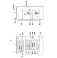
- FIG. It is a block diagram of the charger and battery in the said Embodiment 1.
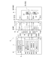
- FIG. It is a block diagram of the charging system of the said Embodiment 1, and a battery.
- FIG. FIG. 7 is a block diagram schematically showing a charging system of a second embodiment.
- FIG. 13 is an explanatory diagram of an identification signal in the charging system of the second embodiment.
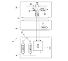
- FIG. 1 shows a charging system S of Embodiment 1 of the present invention.
- the charging system S is capable of charging a plurality of types of secondary batteries 20, and includes a charger A and an adapter B.
- the charger A is commonly used for various secondary batteries 20.
- a plurality of types of adapters B are used corresponding to the types of secondary battery 20. That is, the charging system S of the present embodiment is configured of one charger A commonly used and a plurality of types of adapters B which are alternatively attached to the charger A.
- the charger A incorporates a control unit 1 including a charge control microcomputer.
- the control unit 1 charges the secondary battery 20 in the battery pack 50 connected via the adapter B in accordance with a predetermined charging program. Further, the charger A is provided with the mounting portion 2 to which any one of a plurality of types of adapters B is mounted.
- the adapter B is provided with a mounting portion 10 having a dimension and shape that matches the mounting portion 2 of the charger A.
- the convex mounting portion 10 is fitted and connected to the concave mounting portion 2, but other mounting structures may be used as long as they are mechanically and electrically connected.
- a connection portion 11 for connecting the battery pack 50 is provided at a portion of the adapter B opposite to the mounting portion 10.
- the connection portion 11 has a dimension and shape dedicated to the battery pack 50 that can be connected to the adapter B.
- the adapter B incorporates a resistor unit 12 having a predetermined electrical resistance.
- the resistance portion 12 is electrically connected to the control portion 1 in the charger A when the adapter B is attached to the charger A, and the predetermined electric resistance corresponds to the control portion 1.
- an adapter identification signal to be output is output.
- the battery pack 50 has a connected portion 21 having a dimension and shape that matches the connection portion 11 of the adapter B.
- the convex connected portion 21 is fitted and connected to the concave connection portion 11, other structures may be used as long as they are mechanically and electrically connected. It may be.
- a voltage monitoring unit 22 comprising a cell voltage monitoring IC that monitors the cell voltage of the secondary battery 20, and a thermistor that monitors the temperature of the secondary battery 20.
- a temperature monitoring unit 23 consisting of The voltage monitoring unit 22 and the temperature monitoring unit 23 are electrically connected to the control unit 1 in the charger A via the adapter B, and the voltage monitoring unit 22 outputs a voltage signal to the control unit 1 so that the temperature monitoring unit 23 outputs a temperature signal to the control unit 1.
- a plurality of types of adapters B are prepared in order to enable charging of the plurality of types of battery packs 50. Then, only the adapter B of a dedicated type is connected to the battery pack 50, and the other adapters B are provided so as not to be connected. Whether the connection of the adapter B to the battery pack B is possible or not is determined depending on whether or not the connection portion 11 and the connected portion 21 are mechanically connected.
- control unit 1 of the charger A determines which type of adapter B is attached according to the adapter identification signal output from the resistance unit 12 of the adapter B, that is, a battery having the type of secondary battery 20 Whether the pack 50 is attached can be identified.
- the control unit 1 of the charger A charges the secondary battery 20 of the battery pack 50 according to the charge control program of the system selected based on the output adapter identification signal.
- the charge control here is roughly classified into specific charge control and unspecified charge control.
- the specific charge control is one in which only a plurality of types of charge control are stored in advance as optimum charge control for the specific type of secondary battery 20.
- the nonspecific charge control is stored separately from the plurality of types of specific charge control as charge control that can safely charge the secondary battery 20 other than the specific type.
- charge control combining CC charge and CV charge is performed by a program specific to the secondary battery 20. Specifically, CC charging at a predetermined charging current value is first performed, and when the secondary battery is charged to about 80%, switching to CV charging at a predetermined charging voltage value is performed. The charging voltage value here is changed in a plurality of stages in accordance with the battery temperature detected by the temperature monitoring unit 23.
- the charge voltage value when the detected battery temperature is in the normal temperature range of 10 to 45 ° C., the charge voltage value is set to 4.2 V / cell, and in the high temperature range exceeding 45 ° C., the charge voltage value is The charge voltage value is set to 3.9 V / cell when the temperature is set to 4.0 V / cell and the temperature is lower than 10 ° C.
- the detailed temperature range and the charge voltage value in the temperature range are completely different for each manufacturer of the secondary battery 20.
- the charge current value used in the nonspecific charge control is set to the lowest value or a value lower than that among all the charge current values of the specific charge control stored in multiple types. Specifically, when the lowest value is 2A among the charging current values set in all the specific charging control, the charging current value in the unspecified charging control is set to 2A or a lower value. Further, the charging current value may be set to 2 A in the high temperature range and the low temperature range, and may be set according to the temperature so as to be set to 2.1 A in the normal temperature range. In any case, among all the charging current values of the specific charge control stored in plural types, it may be set to be the lowest value or a value lower than that at each temperature.
- the charging voltage value of the nonspecific charge control is also set to the lowest value or a value lower than that among all the charging voltage values of the specific charge control stored in multiple types. Specifically, among the charge voltage values set in all specific charge control, when the lowest value in the entire temperature range is 3.9 V / cell, the charge voltage value in unspecified charge control is 3 Set to 9 V / cell or lower. Further, the charging voltage value may be set to 3.9 V / cell in the high temperature region and the low temperature region, and may be set according to the temperature so as to be set to 4.1 V / cell in the normal temperature region. In any case, among the charging voltage values of all of the specific charge control stored in plural types, it may be set to be the lowest value or a value lower than that at each temperature.
- charging in which the battery pack 50 is attached is recognized by the adapter identification signal.
- the control unit 1 of the unit A charges the battery pack 50 by appropriate charge control (that is, specific charge control) stored in advance.
- the control unit 1 of the charger A that recognizes by the adapter identification signal that the attached battery pack 50 is other than the specific type is not the specific charge control. Charging is performed by unspecified charging control.
- the charging time is relatively long because the condition is not optimal for the secondary battery 20 of the battery pack 50.
- the charging current value and the charging voltage value are set to the lowest level, charging can be completed safely.
- charging can be completed in a short time and safely for the battery pack 50 of a specific type by selectively using a plurality of types of adapters B, and other types of battery packs can be used.
- the battery pack 50 can safely be charged although it may take some time.
- the output limiting voltage is selected based on the resistance value that the resistor unit 12 has as an adapter identification signal (“adapter identification resistance” in the table).
- the control unit 1 may be provided.
- the control unit 1 is set to stop charging when the charge voltage exceeds the output limit voltage as a safety measure at the time of microcomputer failure or the like.
- the control unit 1 has a plurality of types such as 5 V, 10 V, 20 V, ... as the limiting voltage, and the adapter identification resistance of the mounted adapter B has.
- One of the plurality of limit voltages is selected based on. That is, the control unit 1 in this case has a table in which the charging current, the charging voltage, and the output limit voltage are set based on the adapter identification resistance as shown in Table 1.
- the battery (battery pack) 50 the first battery 500, the second battery 501, the third battery 502, and the fourth battery 503 are illustrated.
- the battery 50 includes a secondary battery 20, a connected portion 21, a voltage monitoring unit 22, a temperature monitoring unit 23, and a housing (battery housing) 8.
- the battery housing 8 is formed in a box shape that houses the secondary battery 20, the voltage monitoring unit 22, and the temperature monitoring unit 23.
- the connected portion 21 is a connector for connecting an external device (a load device, a charger, an adapter or the like).
- the connected portion 21 is provided on the outer surface of the battery housing 8.
- the connected portion 21 includes a positive electrode terminal T211, a negative electrode terminal T212, a voltage output terminal T213, and a temperature output terminal T214.
- the positive electrode terminal T211, the negative electrode terminal T212, the voltage output terminal T213, and the temperature output terminal T214 are all exposed on the outer surface of the battery housing 8.
- the secondary battery 20 is an assembled battery including five battery cells connected in series. Therefore, the voltage of secondary battery 20 is equal to the sum of the voltages of the five battery cells.
- the positive electrode of the secondary battery 20 is connected to the positive electrode terminal T211, and the negative electrode of the secondary battery 20 is connected to the negative electrode terminal T212.
- the battery cell is, for example, a lithium ion battery.
- the battery cell may be a nickel cadmium battery, a nickel hydrogen battery, or the like. Further, the number of battery cells is not limited to five, and the battery cells may be connected in parallel, or may be connected in parallel and in series.
- the type of the secondary battery 20 is different for each of the batteries 500, 501, 502, 503. That is, the batteries 500, 501, 502, 503 have different types of secondary batteries 20 (200, 201, 202, 203). Therefore, the optimal charging method of the secondary battery 20 is different for each battery 50.
- the voltage monitoring unit 22 is configured to measure the voltage of the secondary battery 20 and to output a voltage signal indicating the measured voltage to the voltage output terminal T213.
- the charger A includes a connector (mounting portion) 2, a charging unit 3, a control unit 1, an external power supply terminal 6, and a housing 7.
- the housing 7 is formed in a box shape that houses the charging unit 3 and the control unit 1.
- the connector 2 is used to connect the battery 50.
- the connector 2 is provided on the outer surface of the housing 7 and is configured to be mechanically coupled to the connected portion 211 of the first battery 500. That is, the connector 2 has a shape corresponding to the connection portion 211 of the first battery 500.
- the connector 2 includes a charge terminal T201, a ground terminal T202, a voltage input terminal T203, a temperature input terminal T204, and an identification terminal T205.
- the charge terminal T201, the ground terminal T202, the voltage input terminal T203, the temperature input terminal T204, and the identification terminal T205 are all exposed on the outer surface of the housing 7.
- the charge terminal T201 is connected to the positive terminal T211
- the ground terminal T202 is connected to the negative terminal T212
- the voltage input terminal T203 is connected to the voltage output terminal T213.
- the terminal T204 is connected to the temperature output terminal T214.
- the first battery 500 does not have a terminal corresponding to the identification terminal T205.
- the shape of the connected portion 21 is different for each of the batteries 500, 501, 502, and 503. Therefore, the batteries 501, 502, 503 can not be connected directly to the connector 2.
- an adapter B (first adapter B1) shown in FIG. 3 is used. Further, in order to connect the third battery 502 to the connector 2, an adapter B (second adapter B2) shown in FIG. 4 is used. Further, in order to connect the fourth battery 503 to the connector 2, an adapter B (third adapter B3) shown in FIG. 5 is used.
- Each adapter B includes a first connector (mounted portion) 10, a second connector (connection portion) 11, a connection circuit 14, a resistance portion 12, and a housing (adapter housing) 9.
- the first connector 10 is a connector for connecting the charger A.
- the first connector 10 is provided on the outer surface of the adapter housing 9 and is configured to be mechanically coupled to the connector 2 of the charger A. That is, the first connector 10 has a shape corresponding to the connector 2 of the charger A.
- the first connector 10 includes a first power terminal T101, a first ground terminal T102, a first voltage terminal T103, a first temperature terminal T104, and a signal terminal T105.
- the first power supply terminal T101, the first ground terminal T102, the first voltage terminal T103, the first temperature terminal T104, and the signal terminal T105 are all exposed on the outer surface of the adapter housing 9.
- the charge terminal T201 is connected to the first power terminal T101
- the ground terminal T202 is connected to the first ground terminal T102
- the voltage input terminal T203 is input to the first voltage terminal T103.
- the terminal T204 is connected to the first temperature terminal T104
- the identification terminal T205 is connected to the signal terminal T105.
- the second connector 11 is a connector for connecting the battery 50.
- the second connector 11 is provided on the outer surface of the adapter housing 9.
- the second connector 11 includes a second power terminal T111, a second ground terminal T112, a second voltage terminal T113, and a second temperature terminal T114.
- the second power supply terminal T111, the second ground terminal T112, the second voltage terminal T113, and the second temperature terminal T114 are all exposed on the outer surface of the adapter housing 9.
- the second power terminal T111 is a positive terminal T211
- the second ground terminal T112 is a negative terminal T212
- the second voltage terminal T113 is a voltage output terminal T213
- a second temperature terminal T114 is connected to the temperature output terminal T214, respectively.
- the shape of the second connector 11 is different for each of the adapters B1, B2, and B3. That is, the adapters B1, B2, and B3 have the second connectors 11 (111, 112, 113) of different shapes.
- the second connector 111 of the first adapter B ⁇ b> 1 is configured to be mechanically coupled to the connected portion 211 of the second battery 501. That is, the second connector 111 has a shape corresponding to the connected portion 211 of the second battery 501.
- the second connector 112 of the second adapter B2 is configured to mechanically couple to the connected portion 212 of the third battery 502. That is, the second connector 112 has a shape corresponding to the connected portion 212 of the third battery 502.
- the second connector 113 of the third adapter B3 is configured to be mechanically coupled to the connected portion 213 of the fourth battery 503. That is, the second connector 113 has a shape corresponding to the connected portion 213 of the fourth battery 503.
- the connection circuit 14 is interposed between the first connector 10 and the second connector 11 and configured to electrically connect the second connector 11 to the first connector 10.
- the connection circuit 14 uses the second power terminal T111 as the first power terminal T101, the second ground terminal T112 as the first ground terminal T102, the second voltage terminal T113 as the first voltage terminal T103, and the second temperature terminal T114.
- the first temperature terminals T104 have connection portions 141, 142, 143, and 144 connected respectively.
- the resistor unit 12 is connected between the signal terminal T105 and the first ground terminal T102.
- the resistance value of the resistor unit 12 is determined according to the battery 50 directly connected to the second connector 11. That is, the resistance value of the resistor unit 12 indicates the type of the battery 50. Therefore, in the present embodiment, the resistance unit 12 is an identification unit having information indicating a non-compliant battery directly connected to the second connector 11. For example, the resistance value of the resistor portion 12 of the first adapter B1 is 1 k ⁇ , the resistance value of the resistor portion 12 of the second adapter B2 is 4.3 k ⁇ , and the resistance value of the resistor portion 12 of the third adapter B3 is 0.5 k ⁇ .
- the charging unit 3 is configured to charge the battery 50 connected to the connector 2.
- the charging unit 3 has a main charging unit 31 and a sub charging unit 32.
- the main charging unit 31 is configured to charge the corresponding battery (first battery 500) under main charging conditions suitable for the corresponding battery (first battery 500).
- the circuit configuration of the main charging unit 31 is selected such that the corresponding battery can be charged under the optimum charging condition.
- Main charging unit 31 determines, for example, an AC / DC converter that generates a DC voltage of a predetermined value based on AC power obtained through external connection terminal 6, and a DC voltage obtained from AC / DC converter.
- the main charging unit 31 includes a filter and the like as needed. If the external power supply is a DC power supply, a DC / DC converter is used instead of the AC / DC converter.
- the main charging unit 31 performs charging by supplying a predetermined constant current to the corresponding battery until the voltage of the corresponding battery reaches the predetermined threshold or more, and when the voltage of the corresponding battery becomes equal to or more than the predetermined threshold It is configured to charge the battery by applying a constant voltage to the corresponding battery.
- the predetermined threshold, the value of the constant current, and the value of the constant voltage are determined in accordance with the corresponding battery 50. Therefore, according to the main charging unit 31, the corresponding battery 50 can be charged under the optimal charging condition.
- Secondary charging unit 32 is a non-compliant battery (second battery 501, third battery 502, fourth) under a secondary charging condition that does not adversely affect non-compliant batteries (second battery 501, third battery 502, fourth battery 503). It is controlled to charge the battery 503).
- the secondary charging unit 32 adopts a charging method that can safely charge the secondary battery 20 that may be connected to the charger A regardless of the type.
- the secondary charging unit 32 may be configured to supply a constant current to the non-compliant battery to charge the non-compliant battery.
- the secondary charging unit 32 may be configured to provide a constant voltage to the non-compliant battery to charge the non-compliant battery.
- the secondary charging unit 32 charges the non-compliant battery by supplying a predetermined constant current to the non-compliant battery until the voltage of the non-compliant battery becomes equal to or higher than the predetermined threshold. It is configured to charge the non-compliant battery by applying a constant voltage.
- the predetermined threshold, the value of the constant current, and the value of the constant voltage are determined by the sub charge condition.
- an electric circuit that constitutes the main charging unit 31 is also used as the sub charging unit 32.
- another electric circuit may be used for the main charging unit 31 and the sub charging unit 32.
- the control unit 1 includes an identification unit 41, a control unit 42, a storage unit 43, and a voltage acquisition unit 44.
- the voltage acquisition unit 44 is configured to acquire the voltage of the battery 50 connected to the connector 2.
- the voltage acquisition unit 44 is configured to receive, for example, a voltage signal from the voltage monitoring unit 22 of the battery 50 via the voltage input terminal T203.
- the voltage acquisition unit 44 is configured to acquire the voltage of the battery 50 based on the received voltage signal. Further, the voltage acquisition unit 44 may measure the voltage of the battery 50 by measuring the voltage between the charge terminal T201 and the ground terminal T202.
- the voltage acquisition unit 44 is configured to notify the control unit 42 of the voltage of the battery 50.
- the storage unit 43 is configured to store a plurality of secondary charging conditions.
- the secondary charging unit 32 charges the non-compliant battery by supplying a predetermined constant current to the non-compliant battery until the voltage of the non-compliant battery becomes equal to or higher than the predetermined threshold. Then, the battery is charged by applying a predetermined constant voltage to the non-compliant battery.
- the secondary charging conditions include a charging current indicating the value of the constant current supplied to battery 50 and a charging voltage indicating the value of the constant voltage applied to battery 50.
- the sub charge condition includes an output limit voltage indicating a threshold value for stopping charging of battery 50.
- the secondary charge condition is defined as a condition for charging a non-compliant battery so as not to adversely affect the non-compliant battery. Therefore, the charging current and the charging voltage of the secondary charging condition are set to values that do not adversely affect non-compliant batteries. That is, the secondary charging condition is a condition that can safely charge the non-compliant battery even if it takes time.
- the plurality of secondary charging conditions include a plurality of specific charging conditions (see Table 1) respectively corresponding to a plurality of specific batteries belonging to the non-compliant battery and an unspecified charging condition.
- the second battery 501 and the third battery 502 correspond to a specific battery.
- the specific charge condition of the second battery 501 is determined according to the type of the secondary battery 201 of the second battery 501.
- the charging current for the specific charging condition of the second battery 501 is 1 A
- the charging voltage is 3.9 V / cell
- the output limiting voltage is 5 V.
- the specific charge condition of the third battery 502 is determined according to the type of the secondary battery 202 of the third battery 502.
- the charge current of the specific charge condition of the third battery 502 is 3 A
- the charge voltage is 4.0 V / cell
- the output limit voltage is 20 V.
- the nonspecific charge condition is a charge condition corresponding to a battery (unspecified battery) which does not correspond to any of a plurality of specific batteries among non-compliant batteries. That is, any battery 50 corresponding to the non-specific battery is charged by the non-specific charge condition.
- the fourth battery 503 is a non-compliant battery, but does not correspond to a specific battery, and thus corresponds to a non-specific battery.
- the non-specific conditions are set to relatively low values of charging current and charging voltage so that charging can be performed without any adverse effect on any non-specific battery.
- the value of the constant current indicated by the unspecified charging condition is set equal to or less than the lowest value of the values of the constant current indicated by a plurality of specified charging conditions.
- the value of the constant voltage indicated by the unspecified charging condition is set to be equal to or less than the minimum value of the values of the constant voltage indicated by the plurality of specified charging conditions.
- the value of the output limit voltage indicated by the non-specific charge condition is set to be equal to or less than the minimum value of the output limit voltage indicated by the plurality of specific charge conditions.
- the specific battery is the second battery 501 and the third battery 502. That is, the secondary batteries 20 of the second battery 501 and the third battery 503 are a specific type of secondary battery. Therefore, specific charge control is performed on the second battery 501 and the third battery 503.
- the fourth battery 503 is an unspecified battery
- the secondary battery 203 of the fourth battery 503 is a secondary battery other than the specific type. Therefore, unspecified charging control is performed on the fourth battery 503.
- the charging current of the unspecified charging condition is set to 0.5 A or less, which is equal to or less than the minimum value (1 A) of the value of the constant current indicated by the specified charging condition of the second battery 501 and the third battery 502.
- the charging voltage of the nonspecific charging condition is set to 3.9 V, which is lower than the minimum value (3.9 V) of the value of the constant voltage indicated by the specific charging condition of the second battery 501 and the third battery 502.
- the output limit voltage of the non-specific charge condition is set to 5 V, which is less than the minimum value (5 V) of the output limit voltage indicated by the specific charge condition of the second battery 501 and the third battery 502.
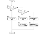
- the identification unit 41 performs an identification process to identify whether the battery 50 connected to the connector 2 is a compatible battery or a non-compliant battery, and outputs the result of the identification process (identification result) to the control unit 42.
- the identification unit 41 may be any of a plurality of specific batteries or any of a plurality of specific batteries. It is configured to identify whether there is no unspecified battery.
- control unit 42 determines whether the voltage acquired by the voltage acquisition unit 44 has become equal to or higher than a predetermined threshold (output limit voltage), and the voltage acquired by the voltage acquisition unit 44 becomes equal to or higher than the predetermined threshold. If it judges, it will be comprised so that operation
- a predetermined threshold output limit voltage
- FIG. 7 shows the charging system S of the present embodiment.
- the charging system S of the first embodiment described based on FIG. 1 most of the configuration of the charging system S of the present embodiment is common. Therefore, in the following, only the differences from the first embodiment among the configurations of the present embodiment will be described in detail.
Landscapes
- Engineering & Computer Science (AREA)
- Power Engineering (AREA)
- Charge And Discharge Circuits For Batteries Or The Like (AREA)
- Secondary Cells (AREA)
Abstract
A battery charger is provided with a contact to which a battery is connected, an identification unit, a primary charging unit, a secondary charging unit, and a control unit. The identification unit is configured in such a manner as to perform identification processing for identifying whether the battery that is connected to the connector is a compatible battery that directly connects to the connector, or an incompatible battery that indirectly connects to the connector, and to output the identification processing result. The primary charging unit is configured in such a manner as to charge the compatible battery under primary charging conditions suited to the compatible battery. The secondary charging unit is configured in such a manner as to charge the incompatible battery under second charging conditions that will not have an adverse effect on the incompatible battery. The control unit is configured in such a manner as to receive the result from the identification unit, activate the primary charging unit if the result indicates the compatible battery, or activate the secondary charging unit if the result indicates the incompatible battery.
Description
本発明は、充電器、アダプタ及びこれらを用いて構成される充電システムに関する。
The present invention relates to a charger, an adapter, and a charging system configured using these.
電動機器の電源となる二次電池は、電池パック等に内蔵されるものであり、充電器を用いて充電される。これら二次電池としては、複数の製造メーカーが各種のものを提供している。
A secondary battery that is a power source of the electric device is built in a battery pack or the like, and is charged using a charger. As these secondary batteries, various manufacturers provide various ones.
文献1(日本国公開特許公報平1-319270号)や文献2(日本国公開特許公報2004-289897号)には、それぞれの二次電池(電池パック)に対応したアダプタを複数用意しておき、これらアダプタを介して、複数種の二次電池を共通の充電器に接続させることが提案されている。
A plurality of adapters corresponding to the respective secondary batteries (battery packs) are prepared in Document 1 (Japanese Patent Application Publication No. 1-319270) and Document 2 (Japanese Application Patent Publication No. 2004-289897). It has been proposed to connect a plurality of types of secondary batteries to a common charger via these adapters.
二次電池において、その製造メーカーや種類が異なると、それぞれ適切な充電方式が異なる。ここでの充電方式とは、例えば、定電流充電(以下「CC充電」という。)を行う際の充電電流値や、定電圧充電(以下「CV充電」という。)を行う際の充電電圧値であり、製造メーカーごとに特有の方式が存在する。なお、一般的に二次電池の充電では、まず所定の充電電流値でのCC充電を行い、二次電池が80%程度にまで充填された時点でCC充電を停止し、その後は所定の充電電圧値でのCV充電を行う。
In the secondary battery, when the manufacturer or the type is different, the appropriate charging method is different. The charging method here is, for example, a charging current value when performing constant current charging (hereinafter referred to as "CC charging") or a charging voltage value when performing constant voltage charging (hereinafter referred to as "CV charging"). There is a system specific to each manufacturer. In general, in charging secondary batteries, first CC charging at a predetermined charging current value is performed, and when secondary batteries are charged to about 80%, CC charging is stopped, and thereafter predetermined charging is performed. Perform CV charge at voltage value.
前記した従来の充電器であれば、複数種の二次電池を、アダプタを介在させることで、共通の充電器によって充電することが可能である。しかし、その場合には、充電方式がその二次電池にとって適切な方式とならない場合(つまり、適切な条件でのCC充電やCV充電とならない場合)がある。充電が適切な方式で行われない場合には、二次電池の寿命や充電の安全性等に悪影響を及ぼすおそれがある。
With the above-described conventional charger, it is possible to charge a plurality of types of secondary batteries with a common charger by interposing an adapter. However, in that case, there are cases where the charging method does not become an appropriate method for the secondary battery (that is, cases where CC charging and CV charging under appropriate conditions are not achieved). If charging is not performed in an appropriate manner, the life of the secondary battery and the safety of charging may be adversely affected.
本発明は、前記問題点に鑑みて発明したものであって、種類が異なる複数の二次電池であっても、それぞれを適当な充電方式で簡単に充電することのできる充電器、アダプタ及び充電システムを提案する。
The present invention has been invented in view of the above-mentioned problems, and it is possible to easily charge a plurality of secondary batteries of different types by an appropriate charging method, an adapter, and a charging device. We propose a system.
本発明の充電器の第1の形態は、バッテリが接続されるコネクタと、前記コネクタに接続されている前記バッテリが、前記コネクタに直接的に接続される対応バッテリと、前記コネクタに間接的に接続される非対応バッテリとのいずれであるかを識別する識別処理を行い、前記識別処理の結果を出力する識別ユニットと、前記対応バッテリに適した主充電条件で前記対応バッテリを充電する主充電ユニットと、前記非対応バッテリに悪影響を与えない副充電条件で前記非対応バッテリを充電する副充電ユニットと、前記識別ユニットから前記結果を受け取り、前記結果が前記対応バッテリを示していれば前記主充電ユニットを動作させ、前記結果が前記非対応バッテリを示していれば前記副充電ユニットを動作させる制御ユニットと、を備える。
According to a first embodiment of the charger of the present invention, a connector to which a battery is connected, and a corresponding battery to which the battery connected to the connector is directly connected to the connector, and indirectly to the connector An identification unit that identifies the non-compliant battery to be connected and an identification unit that outputs the result of the identification process, and a main charge that charges the compatible battery under main charge conditions suitable for the compatible battery A unit, a secondary charging unit for charging the non-compliant battery under secondary charging conditions that do not adversely affect the non-compliant battery, the result received from the identification unit and the primary battery if the result indicates the compliant battery A control unit for operating the charging unit and operating the sub-charging unit if the result indicates the non-compliant battery That.
本発明の充電器の第2の形態は、第1の形態において、記憶ユニットをさらに備える。前記記憶ユニットは、複数の前記副充電条件を記憶するように構成される。前記複数の副充電条件は、前記非対応バッテリに属する複数の特定バッテリにそれぞれ対応する複数の特定充電条件と、不特定充電条件とを含む。前記識別ユニットは、前記識別処理において、前記コネクタに接続されている前記バッテリが前記非対応バッテリである場合には、さらに、前記複数の特定バッテリのいずれか、又は、前記複数の特定バッテリのいずれかでもない不特定バッテリであるかを識別するように構成される。前記制御ユニットは、前記結果が前記特定バッテリを示していれば、前記結果が示す前記特定バッテリに対応する前記特定充電条件を前記記憶ユニットから取得し、取得した前記特定充電条件に従って前記副充電ユニットを制御し、前記結果が前記不特定バッテリを示していれば、前記不特定充電条件を前記記憶ユニットから取得し、前記不特定充電条件に従って前記副充電ユニットを制御するように構成される。
The second form of the charger of the present invention further comprises, in the first form, a storage unit. The storage unit is configured to store a plurality of the secondary charging conditions. The plurality of auxiliary charging conditions include a plurality of specific charging conditions respectively corresponding to a plurality of specific batteries belonging to the non-compliant battery and an unspecified charging condition. In the identification process, when the battery connected to the connector is the non-compliant battery in the identification process, the identification unit further includes any one of the plurality of specific batteries or any of the plurality of specific batteries It is configured to identify whether it is an unspecified battery or not. The control unit acquires the specific charge condition corresponding to the specific battery indicated by the result from the storage unit if the result indicates the specific battery, and the sub-charge unit according to the acquired specific charge condition If the result indicates the non-specific battery, the non-specific charge condition is acquired from the storage unit, and the sub-charge unit is controlled according to the non-specific charge condition.
本発明の充電器の第3の形態では、第2の形態において、前記副充電ユニットは、前記非対応バッテリに定電流を供給して前記非対応バッテリを充電するように構成される。前記副充電条件は、前記定電流の値を示すように構成される。前記不特定充電条件が示す前記定電流の値は、前記複数の特定充電条件が示す前記定電流の値の最低値以下に設定される。
In a third aspect of the charger of the present invention, in the second aspect, the sub charging unit is configured to supply a constant current to the non-compliant battery to charge the non-compliant battery. The sub charge condition is configured to indicate the value of the constant current. The value of the constant current indicated by the unspecified charging condition is set to be equal to or less than the lowest value of the constant current indicated by the plurality of specific charging conditions.
本発明の充電器の第4の形態では、第2または第3の形態において、前記副充電ユニットは、前記非対応バッテリに定電圧を与えて前記非対応バッテリを充電するように構成される。前記副充電条件は、前記定電圧の値を示すように構成される。前記不特定充電条件が示す前記定電圧の値は、前記複数の特定充電条件が示す前記定電圧の値の最低値以下に設定される。
In a fourth aspect of the charger of the present invention, in the second or third aspect, the sub charging unit is configured to apply a constant voltage to the non-compliant battery to charge the non-compliant battery. The sub charge condition is configured to indicate the value of the constant voltage. The value of the constant voltage indicated by the unspecified charging condition is set to be equal to or less than the lowest value of the values of the constant voltage indicated by the plurality of specific charging conditions.
本発明の充電器の第5の形態は、第2~第4の形態のうちいずれか1つにおいて、前記コネクタに接続された前記バッテリの電圧を取得する電圧取得ユニットをさらに備える。前記制御ユニットは、前記電圧取得ユニットで取得された前記電圧が所定の閾値以上になったかどうかを判断し、前記電圧取得ユニットで取得された前記電圧が所定の閾値以上になったと判断すると前記副充電ユニットの動作を停止させるように構成される。前記副充電条件は、前記所定の閾値を示すように構成される。
The 5th form of the charger of this invention is further provided with the voltage acquisition unit which acquires the voltage of the said battery connected to the said connector in any one of the 2nd-4th forms. The control unit determines whether the voltage acquired by the voltage acquisition unit is equal to or higher than a predetermined threshold, and determines that the voltage acquired by the voltage acquisition unit is equal to or higher than the predetermined threshold. It is configured to stop the operation of the charging unit. The sub charge condition is configured to indicate the predetermined threshold.
本発明の充電器の第6の形態では、第1~第5の形態のうちいずれか1つにおいて、前記識別ユニットは、前記コネクタに前記バッテリが接続された際に前記バッテリの種類を示す種別情報を取得する取得回路と、前記取得回路が取得した前記種別情報に基づいて前記識別処理を実行する識別回路と、を備える。
In the sixth aspect of the charger according to the present invention, in any one of the first to fifth aspects, the identification unit indicates a type of the battery when the battery is connected to the connector. An acquisition circuit for acquiring information, and an identification circuit for performing the identification process based on the type information acquired by the acquisition circuit.
本発明の充電器の第7の形態では、第6の形態において、前記コネクタは、前記バッテリの種類を識別するための2つの識別端子を有する。前記取得回路は、前記2つの識別端子間の抵抗値を測定するように構成される。前記種別情報は、前記2つの識別端子間の抵抗値で定義される。
In a seventh aspect of the charger of the present invention, in the sixth aspect, the connector has two identification terminals for identifying the type of the battery. The acquisition circuit is configured to measure a resistance between the two identification terminals. The type information is defined by a resistance value between the two identification terminals.
本発明の充電器の第8の形態では、第6の形態において、前記コネクタは、前記バッテリの種類を識別するための1つの識別端子を有する。前記取得回路は、前記識別端子を通じて前記種別情報を示す識別信号を受け取るように構成される。
In an eighth aspect of the charger of the present invention, in the sixth aspect, the connector has one identification terminal for identifying the type of the battery. The acquisition circuit is configured to receive an identification signal indicating the type information through the identification terminal.
本発明のアダプタの一形態は、第1~第8のうちいずれか1つの充電器の前記コネクタが直接的に接続される第1コネクタと、前記非対応バッテリが直接的に接続される第2コネクタと、前記第1コネクタと前記第2コネクタとの間に介在され前記第2コネクタを前記第1コネクタに電気的に接続する接続回路と、前記第2コネクタに直接的に接続される前記非対応バッテリを示す情報を有する識別部と、を備える。
One form of the adapter of the present invention is a first connector to which the connector of any one of the first to eighth chargers is directly connected, and a second to which the non-corresponding battery is directly connected. A connector, a connection circuit interposed between the first connector and the second connector and electrically connecting the second connector to the first connector, and the non-directly connected to the second connector An identification unit having information indicating a corresponding battery.
本発明の充電システムの一形態は、第1~第8のうちいずれか1つの充電器と、アダプタと、を備える。前記アダプタは、前記充電器の前記コネクタが直接的に接続される第1コネクタと、前記非対応バッテリが直接的に接続される第2コネクタと、前記第1コネクタと前記第2コネクタとの間に介在され前記第2コネクタを前記第1コネクタに電気的に接続する接続回路と、前記第2コネクタに直接的に接続される前記非対応バッテリを示す情報を有する識別部と、を備える。
One form of the charging system of the present invention includes any one of the first to eighth chargers and an adapter. The adapter is provided between a first connector to which the connector of the charger is directly connected, a second connector to which the incompatible battery is directly connected, and the first connector and the second connector. A connection circuit that electrically connects the second connector to the first connector, and an identification unit having information indicating the incompatible battery directly connected to the second connector.
(実施形態1)
図1には、本発明の実施形態1の充電システムSを示している。この充電システムSは、複数種の二次電池20を充電可能とするものであり、充電器Aと、アダプタBとで構成される。充電器Aは、各種の二次電池20に対して共通に利用されるものである。一方、アダプタBは、二次電池20の種類に対応して複数種のものが利用される。つまり、本実施形態の充電システムSは、共通に用いられる1つの充電器Aと、この充電器Aに対して択一的に装着される複数種のアダプタBとで、構成される。 (Embodiment 1)
FIG. 1 shows a charging system S ofEmbodiment 1 of the present invention. The charging system S is capable of charging a plurality of types of secondary batteries 20, and includes a charger A and an adapter B. The charger A is commonly used for various secondary batteries 20. On the other hand, a plurality of types of adapters B are used corresponding to the types of secondary battery 20. That is, the charging system S of the present embodiment is configured of one charger A commonly used and a plurality of types of adapters B which are alternatively attached to the charger A.
図1には、本発明の実施形態1の充電システムSを示している。この充電システムSは、複数種の二次電池20を充電可能とするものであり、充電器Aと、アダプタBとで構成される。充電器Aは、各種の二次電池20に対して共通に利用されるものである。一方、アダプタBは、二次電池20の種類に対応して複数種のものが利用される。つまり、本実施形態の充電システムSは、共通に用いられる1つの充電器Aと、この充電器Aに対して択一的に装着される複数種のアダプタBとで、構成される。 (Embodiment 1)
FIG. 1 shows a charging system S of
充電器Aには、充電制御マイコンから成る制御部1が内蔵されている。この制御部1は、アダプタBを介して接続される電池パック50内の二次電池20に対して、既定の充電プログラムにしたがって充電を行うものである。また、充電器Aには、複数種のアダプタBのうちいずれか1つが装着される装着部2を設けている。
The charger A incorporates a control unit 1 including a charge control microcomputer. The control unit 1 charges the secondary battery 20 in the battery pack 50 connected via the adapter B in accordance with a predetermined charging program. Further, the charger A is provided with the mounting portion 2 to which any one of a plurality of types of adapters B is mounted.
アダプタBには、充電器Aの装着部2と合致する寸法形状の被装着部10を設けている。本実施形態では、凹状の装着部2に凸状の被装着部10が嵌合して接続される構造としているが、機械的に且つ電気的に接続される構造であれば、他の装着構造であってもよい。さらに、アダプタBの被装着部10とは反対側の部分に、電池パック50を接続するための接続部11を設けている。接続部11は、このアダプタBに接続させることのできる電池パック50専用の寸法形状を有している。
The adapter B is provided with a mounting portion 10 having a dimension and shape that matches the mounting portion 2 of the charger A. In the present embodiment, the convex mounting portion 10 is fitted and connected to the concave mounting portion 2, but other mounting structures may be used as long as they are mechanically and electrically connected. It may be Furthermore, a connection portion 11 for connecting the battery pack 50 is provided at a portion of the adapter B opposite to the mounting portion 10. The connection portion 11 has a dimension and shape dedicated to the battery pack 50 that can be connected to the adapter B.
また、アダプタBには、所定の電気抵抗を有する抵抗部12が内蔵されている。この抵抗部12は、アダプタBが充電器Aに装着されたときに該充電器A内の制御部1に対して電気接続されるものであり、前記所定の電気抵抗が、制御部1に対して出力されるアダプタ識別信号となる。
Further, the adapter B incorporates a resistor unit 12 having a predetermined electrical resistance. The resistance portion 12 is electrically connected to the control portion 1 in the charger A when the adapter B is attached to the charger A, and the predetermined electric resistance corresponds to the control portion 1. And an adapter identification signal to be output.
電池パック50は、アダプタBの接続部11と合致する寸法形状の被接続部21を有する。本実施形態では、凹状の接続部11に凸状の被接続部21が嵌合して接続される構造としているが、機械的に且つ電気的に接続される構造であれば、他の構造であってもよい。
The battery pack 50 has a connected portion 21 having a dimension and shape that matches the connection portion 11 of the adapter B. In the present embodiment, although the convex connected portion 21 is fitted and connected to the concave connection portion 11, other structures may be used as long as they are mechanically and electrically connected. It may be.
電池パック50には、充電対象である二次電池20に加えて、二次電池20のセル電圧を監視するセル電圧監視ICから成る電圧監視部22と、二次電池20の温度を監視するサーミスタから成る温度監視部23とを内蔵している。電圧監視部22と温度監視部23とは、アダプタBを介して充電器A内の制御部1に電気接続され、電圧監視部22が制御部1に対して電圧信号を出力し、温度監視部23が制御部1に対して温度信号を出力する。
In the battery pack 50, in addition to the secondary battery 20 to be charged, a voltage monitoring unit 22 comprising a cell voltage monitoring IC that monitors the cell voltage of the secondary battery 20, and a thermistor that monitors the temperature of the secondary battery 20. And a temperature monitoring unit 23 consisting of The voltage monitoring unit 22 and the temperature monitoring unit 23 are electrically connected to the control unit 1 in the charger A via the adapter B, and the voltage monitoring unit 22 outputs a voltage signal to the control unit 1 so that the temperature monitoring unit 23 outputs a temperature signal to the control unit 1.
以上のように、本実施形態の充電システムSにおいては、複数種の電池パック50を充電可能とするため、複数種のアダプタBを用意している。そして、電池パック50に対しては、専用の種類のアダプタBだけが接続され、それ以外のアダプタBは接続されないように設けている。電池パックBに対するアダプタBの接続の可不可は、接続部11と被接続部21が機械的に接続されるか否かによって決定される。
As described above, in the charging system S of the present embodiment, a plurality of types of adapters B are prepared in order to enable charging of the plurality of types of battery packs 50. Then, only the adapter B of a dedicated type is connected to the battery pack 50, and the other adapters B are provided so as not to be connected. Whether the connection of the adapter B to the battery pack B is possible or not is determined depending on whether or not the connection portion 11 and the connected portion 21 are mechanically connected.
したがって、充電器Aの制御部1は、アダプタBの抵抗部12から出力されるアダプタ識別信号によって、どの種類のアダプタBが装着されたのか、つまりは、どの種類の二次電池20を有する電池パック50が装着されたのかを、識別することができる。
Therefore, the control unit 1 of the charger A determines which type of adapter B is attached according to the adapter identification signal output from the resistance unit 12 of the adapter B, that is, a battery having the type of secondary battery 20 Whether the pack 50 is attached can be identified.
充電器Aの制御部1は、出力されるアダプタ識別信号に基づいて選択された方式の充電制御プログラムにしたがって、電池パック50の二次電池20を充電する。ここでの充電制御は、特定充電制御と、不特定充電制御とに大別される。特定充電制御は、特定種の二次電池20に対して最適な充電制御として、あらかじめ複数種だけ記憶させたものである。不特定充電制御は、特定種以外の二次電池20に対して安全に充電を行うことのできる充電制御として、前記複数種の特定充電制御とは別に記憶させたものである。
The control unit 1 of the charger A charges the secondary battery 20 of the battery pack 50 according to the charge control program of the system selected based on the output adapter identification signal. The charge control here is roughly classified into specific charge control and unspecified charge control. The specific charge control is one in which only a plurality of types of charge control are stored in advance as optimum charge control for the specific type of secondary battery 20. The nonspecific charge control is stored separately from the plurality of types of specific charge control as charge control that can safely charge the secondary battery 20 other than the specific type.
特定充電制御においては、その二次電池20特有のプログラムで、CC充電やCV充電を組み合わせた充電制御を行う。具体的には、所定の充電電流値でのCC充電をまず行い、二次電池が80%程度にまで充填された時点で、所定の充電電圧値でのCV充電に切り替える。ここでの充電電圧値は、温度監視部23により検知される電池温度に応じて、複数段階で変更される。例えば、検知される電池温度が10~45℃の通常温度域にある場合は、充電電圧値が4.2V/セルに設定され、45℃を超える高温度域となる場合には充電電圧値が4.0V/セルに設定され、10℃を下回る低温度域となる場合には充電電圧値が3.9V/セルに設定される、といった具合である。これらの詳細な温度域や、その温度域での充電電圧値は、二次電池20の製造メーカーごとに全く別のものとなる。
In the specific charge control, charge control combining CC charge and CV charge is performed by a program specific to the secondary battery 20. Specifically, CC charging at a predetermined charging current value is first performed, and when the secondary battery is charged to about 80%, switching to CV charging at a predetermined charging voltage value is performed. The charging voltage value here is changed in a plurality of stages in accordance with the battery temperature detected by the temperature monitoring unit 23. For example, when the detected battery temperature is in the normal temperature range of 10 to 45 ° C., the charge voltage value is set to 4.2 V / cell, and in the high temperature range exceeding 45 ° C., the charge voltage value is The charge voltage value is set to 3.9 V / cell when the temperature is set to 4.0 V / cell and the temperature is lower than 10 ° C. The detailed temperature range and the charge voltage value in the temperature range are completely different for each manufacturer of the secondary battery 20.
不特定充電制御においても、CC充電とCV充電を組み合わせた充電制御を行う。具体的には、不特定充電用に設定した充電電流値でのCC充電をまず行い、その後に、不特定充電用に設定した充電電圧値でのCV充電を行う。
Also in non-specific charge control, charge control combining CC charge and CV charge is performed. Specifically, CC charging is first performed at a charging current value set for unspecified charging, and thereafter CV charging at a charging voltage value set for unspecified charging is performed.
不特定充電制御で用いる充電電流値は、複数種記憶させている特定充電制御の全ての充電電流値のうち、最低値又はそれよりも低い値に設定する。具体的には、全ての特定充電制御において設定される充電電流値のうち、最低値が2Aである場合には、不特定充電制御での充電電流値は2Aかそれより低い値に設定する。また、高温度域と低温度域では充電電流値を2Aに設定し、通常温度域では2.1Aに設定するといったように、温度に対応して設定してもよい。いずれにしても、各温度において、複数種記憶させている特定充電制御の全ての充電電流値のうち、最低値又はそれよりも低い値となるように設定すればよい。
The charge current value used in the nonspecific charge control is set to the lowest value or a value lower than that among all the charge current values of the specific charge control stored in multiple types. Specifically, when the lowest value is 2A among the charging current values set in all the specific charging control, the charging current value in the unspecified charging control is set to 2A or a lower value. Further, the charging current value may be set to 2 A in the high temperature range and the low temperature range, and may be set according to the temperature so as to be set to 2.1 A in the normal temperature range. In any case, among all the charging current values of the specific charge control stored in plural types, it may be set to be the lowest value or a value lower than that at each temperature.
また、不特定充電制御の充電電圧値についても、複数種記憶させている特定充電制御の全ての充電電圧値のうち、最低値又はそれよりも低い値に設定する。具体的には、全ての特定充電制御において設定される充電電圧値のうち、全温度域での最低値が3.9V/セルである場合には、不特定充電制御での充電電圧値は3.9V/セルかそれより低い値に設定する。また、高温度域と低温度域では充電電圧値を3.9V/セルに設定し、通常温度域では4.1V/セルに設定するといったように、温度に対応して設定してもよい。いずれにしても、各温度において、複数種記憶させている特定充電制御の全ての充電電圧値のうち、最低値又はそれよりも低い値となるように設定すればよい。
Further, the charging voltage value of the nonspecific charge control is also set to the lowest value or a value lower than that among all the charging voltage values of the specific charge control stored in multiple types. Specifically, among the charge voltage values set in all specific charge control, when the lowest value in the entire temperature range is 3.9 V / cell, the charge voltage value in unspecified charge control is 3 Set to 9 V / cell or lower. Further, the charging voltage value may be set to 3.9 V / cell in the high temperature region and the low temperature region, and may be set according to the temperature so as to be set to 4.1 V / cell in the normal temperature region. In any case, among the charging voltage values of all of the specific charge control stored in plural types, it may be set to be the lowest value or a value lower than that at each temperature.
したがって、本実施形態の充電システムSによれば、適切な充電制御方法が分かっている特定種の電池パック50に対しては、この電池パック50が装着されたことをアダプタ識別信号により認識した充電器Aの制御部1が、あらかじめ記憶させている適切な充電制御(つまり特定充電制御)によって、電池パック50の充電を行う。
Therefore, according to the charging system S of the present embodiment, for a specific type of battery pack 50 for which an appropriate charge control method is known, charging in which the battery pack 50 is attached is recognized by the adapter identification signal. The control unit 1 of the unit A charges the battery pack 50 by appropriate charge control (that is, specific charge control) stored in advance.
そして、特定種以外の電池パック50に対しては、装着された電池パック50が特定種以外のものであることをアダプタ識別信号により認識した充電器Aの制御部1が、特定充電制御ではなく不特定充電制御によって、充電を実行する。
Then, for the battery pack 50 other than the specific type, the control unit 1 of the charger A that recognizes by the adapter identification signal that the attached battery pack 50 is other than the specific type is not the specific charge control. Charging is performed by unspecified charging control.
不特定充電制御においては、その電池パック50の二次電池20に最適な条件という訳でないため、充電時間が比較的長くなる。しかし、前述したように、充電電流値や充電電圧値を最低水準に設定しているので、安全に充電を完了することができる。
In unspecified charging control, the charging time is relatively long because the condition is not optimal for the secondary battery 20 of the battery pack 50. However, as described above, since the charging current value and the charging voltage value are set to the lowest level, charging can be completed safely.
そのため、本実施形態の充電システムSでは、複数種のアダプタBを使い分けることにより、特定種の電池パック50に対しては短時間で且つ安全に充電を完了することができ、それ以外の種類の電池パック50に対しては、多少時間はかかるものの安全に充電を完了することができる。
Therefore, in the charging system S of the present embodiment, charging can be completed in a short time and safely for the battery pack 50 of a specific type by selectively using a plurality of types of adapters B, and other types of battery packs can be used. The battery pack 50 can safely be charged although it may take some time.
また、充電器Aを購入した後に、新規タイプの二次電池20を有する電池パック50の販売が開始されるような場合であっても、この新規タイプの電池パック50に装着可能な専用形状のアダプタBを別途提供するだけで、対応可能となる。このアダプタBには、特定種以外のものであることを認識させるための抵抗部12を内蔵させておく。使用者は、別途提供されたアダプタBを介してその新規タイプの電池パック50を充電器Aに装着すれば、不特定充電制御のプログラムにしたがって、多少時間はかかるものの安全に充電を完了することができる。つまり、新規の電池パック50を充電するために充電器Aそのものを新たに購入する必要なく、別途提供のアダプタBだけを入手すればよい。
In addition, even if the battery pack 50 having the new type secondary battery 20 is started to be sold after purchasing the charger A, the dedicated shape can be attached to the new type battery pack 50. Only by separately providing the adapter B, it becomes possible to cope with it. The adapter B incorporates a resistor 12 for recognizing that it is other than a specific type. If the user attaches the battery pack 50 of the new type to the charger A via the adapter B provided separately, the user can complete the charging safely though it may take some time according to the program for unspecified charging control Can. That is, it is not necessary to newly purchase the charger A itself in order to charge the new battery pack 50, and only the separately provided adapter B may be obtained.
さらに、下記の表1に例示するように、抵抗部12がアダプタ識別信号として有する抵抗値(表中の「アダプタ識別抵抗」)に基づいて出力制限電圧が選択されるように、充電器Aの制御部1を設けてもよい。制御部1は、マイコン故障時等の安全対策として、充電電圧が出力制限電圧を超えたときには充電を停止させるように設定される。
Furthermore, as exemplified in Table 1 below, in the charger A, the output limiting voltage is selected based on the resistance value that the resistor unit 12 has as an adapter identification signal (“adapter identification resistance” in the table). The control unit 1 may be provided. The control unit 1 is set to stop charging when the charge voltage exceeds the output limit voltage as a safety measure at the time of microcomputer failure or the like.

以下、本実施形態の充電器Aについて詳細に説明する。
Hereinafter, the charger A of the present embodiment will be described in detail.
以下の説明では、バッテリ(電池パック)50として、第1バッテリ500と、第2バッテリ501と、第3バッテリ502と、第4バッテリ503と、を例示する。
In the following description, as the battery (battery pack) 50, the first battery 500, the second battery 501, the third battery 502, and the fourth battery 503 are illustrated.
バッテリ50は、図2に示すように、二次電池20と、被接続部21と、電圧監視部22と、温度監視部23と、ハウジング(バッテリハウジング)8と、を備える。
As shown in FIG. 2, the battery 50 includes a secondary battery 20, a connected portion 21, a voltage monitoring unit 22, a temperature monitoring unit 23, and a housing (battery housing) 8.
バッテリハウジング8は、二次電池20と、電圧監視部22と、温度監視部23とを収納する箱状に形成される。
The battery housing 8 is formed in a box shape that houses the secondary battery 20, the voltage monitoring unit 22, and the temperature monitoring unit 23.
被接続部21は、外部機器(負荷機器や、充電器、アダプタ等)を接続するためのコネクタである。被接続部21は、バッテリハウジング8の外面に設けられている。被接続部21は、正極端子T211と、負極端子T212と、電圧出力端子T213と、温度出力端子T214と、を備える。正極端子T211と、負極端子T212と、電圧出力端子T213と、温度出力端子T214とは、いずれもバッテリハウジング8の外面に露出している。
The connected portion 21 is a connector for connecting an external device (a load device, a charger, an adapter or the like). The connected portion 21 is provided on the outer surface of the battery housing 8. The connected portion 21 includes a positive electrode terminal T211, a negative electrode terminal T212, a voltage output terminal T213, and a temperature output terminal T214. The positive electrode terminal T211, the negative electrode terminal T212, the voltage output terminal T213, and the temperature output terminal T214 are all exposed on the outer surface of the battery housing 8.
ここで、被接続部21の形状は、バッテリ500,501,502,503毎に異なっている。すなわち、バッテリ500,501,502,503は、異なる形状の被接続部21(210,211,212,213)を有している。
Here, the shape of the connected portion 21 is different for each of the batteries 500, 501, 502, 503. That is, the batteries 500, 501, 502, 503 have connected portions 21 (210, 211, 212, 213) of different shapes.
二次電池20は、直列に接続された5つの電池セルを備える組電池である。したがって、二次電池20の電圧は、5つの電池セルの電圧の合計に等しい。二次電池20の正極は正極端子T211に接続され、二次電池20の負極は負極端子T212に接続されている。
The secondary battery 20 is an assembled battery including five battery cells connected in series. Therefore, the voltage of secondary battery 20 is equal to the sum of the voltages of the five battery cells. The positive electrode of the secondary battery 20 is connected to the positive electrode terminal T211, and the negative electrode of the secondary battery 20 is connected to the negative electrode terminal T212.
電池セルは、たとえば、リチウムイオン電池である。なお、電池セルは、ニッケルカドミウム電池や、ニッケル水素電池などであってもよい。また、電池セルの数は5つに限定されず、また、電池セルは並列に接続されていてもよいし、並列および直列に接続されていてもよい。
The battery cell is, for example, a lithium ion battery. The battery cell may be a nickel cadmium battery, a nickel hydrogen battery, or the like. Further, the number of battery cells is not limited to five, and the battery cells may be connected in parallel, or may be connected in parallel and in series.
ここで、二次電池20の種類は、バッテリ500,501,502,503毎に異なっている。すなわち、バッテリ500,501,502,503は、異なる種類の二次電池20(200,201,202,203)を有している。そのため、二次電池20の最適な充電の方法は、バッテリ50毎に異なっている。
Here, the type of the secondary battery 20 is different for each of the batteries 500, 501, 502, 503. That is, the batteries 500, 501, 502, 503 have different types of secondary batteries 20 (200, 201, 202, 203). Therefore, the optimal charging method of the secondary battery 20 is different for each battery 50.
電圧監視部22は、二次電池20の電圧を測定し、測定した電圧を示す電圧信号を電圧出力端子T213に出力するように構成される。
The voltage monitoring unit 22 is configured to measure the voltage of the secondary battery 20 and to output a voltage signal indicating the measured voltage to the voltage output terminal T213.
温度監視部23は、二次電池20の温度を測定し、測定した温度を示す温度信号を温度出力端子T214に出力するように構成される。
The temperature monitoring unit 23 is configured to measure the temperature of the secondary battery 20 and to output a temperature signal indicating the measured temperature to the temperature output terminal T214.
本実施形態の充電器Aは、図2~図5に示すように、コネクタ(装着部)2と、充電部3と、制御部1と、外部電源端子6と、ハウジング7と、を備える。
As shown in FIGS. 2 to 5, the charger A according to the present embodiment includes a connector (mounting portion) 2, a charging unit 3, a control unit 1, an external power supply terminal 6, and a housing 7.
ハウジング7は、充電部3および制御部1を収納する箱状に形成される。
The housing 7 is formed in a box shape that houses the charging unit 3 and the control unit 1.
外部電源端子6は、ハウジング7の外面に設けられている。外部電源端子6は、外部電源が接続されるように構成される。本実施形態において、外部電源は、交流電源(たとえば、商用交流電源)である。なお、外部電源は、直流電源であってもよい。
The external power supply terminal 6 is provided on the outer surface of the housing 7. The external power supply terminal 6 is configured to be connected to an external power supply. In the present embodiment, the external power source is an AC power source (for example, a commercial AC power source). The external power supply may be a DC power supply.
コネクタ2は、バッテリ50を接続するために用いられる。コネクタ2は、ハウジング7の外面に設けられ、第1バッテリ500の被接続部211に機械的に結合するように構成されている。すなわち、コネクタ2は、第1バッテリ500の接続部211に対応する形状を有している。
The connector 2 is used to connect the battery 50. The connector 2 is provided on the outer surface of the housing 7 and is configured to be mechanically coupled to the connected portion 211 of the first battery 500. That is, the connector 2 has a shape corresponding to the connection portion 211 of the first battery 500.
また、コネクタ2は、充電端子T201と、接地端子T202と、電圧入力端子T203と、温度入力端子T204と、識別端子T205と、を備える。充電端子T201と、接地端子T202と、電圧入力端子T203と、温度入力端子T204と、識別端子T205と、はいずれもハウジング7の外面に露出している。
Further, the connector 2 includes a charge terminal T201, a ground terminal T202, a voltage input terminal T203, a temperature input terminal T204, and an identification terminal T205. The charge terminal T201, the ground terminal T202, the voltage input terminal T203, the temperature input terminal T204, and the identification terminal T205 are all exposed on the outer surface of the housing 7.
コネクタ2に第1バッテリ500の被接続部210を接続した際には、充電端子T201が正極端子T211に、接地端子T202が負極端子T212に、電圧入力端子T203が電圧出力端子T213に、温度入力端子T204が温度出力端子T214に、それぞれ接続される。なお、第1バッテリ500は、識別端子T205に対応する端子を有していない。
When the connected part 210 of the first battery 500 is connected to the connector 2, the charge terminal T201 is connected to the positive terminal T211, the ground terminal T202 is connected to the negative terminal T212, and the voltage input terminal T203 is connected to the voltage output terminal T213. The terminal T204 is connected to the temperature output terminal T214. The first battery 500 does not have a terminal corresponding to the identification terminal T205.
上述したように、被接続部21の形状は、バッテリ500,501,502,503毎に異なっている。そのため、バッテリ501,502,503は、コネクタ2に直接的には接続することはできない。
As described above, the shape of the connected portion 21 is different for each of the batteries 500, 501, 502, and 503. Therefore, the batteries 501, 502, 503 can not be connected directly to the connector 2.
そこで、第2バッテリ501をコネクタ2に接続するためには、図3に示すアダプタB(第1アダプタB1)が用いられる。また、第3バッテリ502をコネクタ2に接続するためには、図4に示すアダプタB(第2アダプタB2)が用いられる。また、第4バッテリ503をコネクタ2に接続するためには、図5に示すアダプタB(第3アダプタB3)が用いられる。
Therefore, in order to connect the second battery 501 to the connector 2, an adapter B (first adapter B1) shown in FIG. 3 is used. Further, in order to connect the third battery 502 to the connector 2, an adapter B (second adapter B2) shown in FIG. 4 is used. Further, in order to connect the fourth battery 503 to the connector 2, an adapter B (third adapter B3) shown in FIG. 5 is used.
すなわち、本実施形態では、第1バッテリ500はコネクタ2に直接的に接続される対応バッテリであり、第2、第3、第4バッテリ501,502,503は、コネクタ2に(アダプタBを用いて)間接的に接続される非対応バッテリである。
That is, in the present embodiment, the first battery 500 is a corresponding battery directly connected to the connector 2, and the second, third, and fourth batteries 501, 502, and 503 are connected to the connector 2 (using the adapter B. ) Indirectly connected.
各アダプタBは、第1コネクタ(被装着部)10と、第2コネクタ(接続部)11と、接続回路14と、抵抗部12と、ハウジング(アダプタハウジング)9と、を備える。
Each adapter B includes a first connector (mounted portion) 10, a second connector (connection portion) 11, a connection circuit 14, a resistance portion 12, and a housing (adapter housing) 9.
アダプタハウジング9は、接続回路14と、抵抗部12とを収納する箱状に形成される。
The adapter housing 9 is formed in a box shape that houses the connection circuit 14 and the resistance portion 12.
第1コネクタ10は、充電器Aを接続するためのコネクタである。第1コネクタ10は、アダプタハウジング9の外面に設けられ、充電器Aのコネクタ2に機械的に結合するように構成されている。すなわち、第1コネクタ10は、充電器Aのコネクタ2に対応する形状を有している。
The first connector 10 is a connector for connecting the charger A. The first connector 10 is provided on the outer surface of the adapter housing 9 and is configured to be mechanically coupled to the connector 2 of the charger A. That is, the first connector 10 has a shape corresponding to the connector 2 of the charger A.
第1コネクタ10は、第1電源端子T101と、第1接地端子T102と、第1電圧端子T103と、第1温度端子T104と、信号端子T105と、を備える。第1電源端子T101と、第1接地端子T102と、第1電圧端子T103と、第1温度端子T104と、信号端子T105とは、いずれもアダプタハウジング9の外面に露出している。
The first connector 10 includes a first power terminal T101, a first ground terminal T102, a first voltage terminal T103, a first temperature terminal T104, and a signal terminal T105. The first power supply terminal T101, the first ground terminal T102, the first voltage terminal T103, the first temperature terminal T104, and the signal terminal T105 are all exposed on the outer surface of the adapter housing 9.
コネクタ2に第1コネクタ10を接続した際には、充電端子T201が第1電源端子T101に、接地端子T202が第1接地端子T102に、電圧入力端子T203が第1電圧端子T103に、温度入力端子T204が第1温度端子T104に、識別端子T205が信号端子T105に、それぞれ接続される。
When the first connector 10 is connected to the connector 2, the charge terminal T201 is connected to the first power terminal T101, the ground terminal T202 is connected to the first ground terminal T102, and the voltage input terminal T203 is input to the first voltage terminal T103. The terminal T204 is connected to the first temperature terminal T104, and the identification terminal T205 is connected to the signal terminal T105.
第2コネクタ11は、バッテリ50を接続するためのコネクタである。第2コネクタ11は、アダプタハウジング9の外面に設けられている。
The second connector 11 is a connector for connecting the battery 50. The second connector 11 is provided on the outer surface of the adapter housing 9.
また、第2コネクタ11は、第2電源端子T111と、第2接地端子T112と、第2電圧端子T113と、第2温度端子T114と、を備える。第2電源端子T111と、第2接地端子T112と、第2電圧端子T113と、第2温度端子T114とは、いずれもアダプタハウジング9の外面に露出している。
In addition, the second connector 11 includes a second power terminal T111, a second ground terminal T112, a second voltage terminal T113, and a second temperature terminal T114. The second power supply terminal T111, the second ground terminal T112, the second voltage terminal T113, and the second temperature terminal T114 are all exposed on the outer surface of the adapter housing 9.
アダプタBにバッテリ50を接続した際には、第2電源端子T111が正極端子T211に、第2接地端子T112が負極端子T212に、第2電圧端子T113が電圧出力端子T213に、第2温度端子T114が温度出力端子T214に、それぞれ接続される。
When the battery 50 is connected to the adapter B, the second power terminal T111 is a positive terminal T211, the second ground terminal T112 is a negative terminal T212, the second voltage terminal T113 is a voltage output terminal T213, and a second temperature terminal T114 is connected to the temperature output terminal T214, respectively.
ここで、第2コネクタ11の形状は、アダプタB1,B2,B3毎に異なっている。すなわち、アダプタB1,B2,B3は、異なる形状の第2コネクタ11(111,112,113)を有している。
Here, the shape of the second connector 11 is different for each of the adapters B1, B2, and B3. That is, the adapters B1, B2, and B3 have the second connectors 11 (111, 112, 113) of different shapes.
第1アダプタB1の第2コネクタ111は、第2バッテリ501の被接続部211に機械的に結合するように構成されている。すなわち、第2コネクタ111は、第2バッテリ501の被接続部211に対応する形状を有している。
The second connector 111 of the first adapter B <b> 1 is configured to be mechanically coupled to the connected portion 211 of the second battery 501. That is, the second connector 111 has a shape corresponding to the connected portion 211 of the second battery 501.
第2アダプタB2の第2コネクタ112は、第3バッテリ502の被接続部212に機械的に結合するように構成されている。すなわち、第2コネクタ112は、第3バッテリ502の被接続部212に対応する形状を有している。
The second connector 112 of the second adapter B2 is configured to mechanically couple to the connected portion 212 of the third battery 502. That is, the second connector 112 has a shape corresponding to the connected portion 212 of the third battery 502.
第3アダプタB3の第2コネクタ113は、第4バッテリ503の被接続部213に機械的に結合するように構成されている。すなわち、第2コネクタ113は、第4バッテリ503の被接続部213に対応する形状を有している。
The second connector 113 of the third adapter B3 is configured to be mechanically coupled to the connected portion 213 of the fourth battery 503. That is, the second connector 113 has a shape corresponding to the connected portion 213 of the fourth battery 503.
接続回路14は、第1コネクタ10と第2コネクタ11との間に介在され第2コネクタ11を第1コネクタ10に電気的に接続するように構成される。接続回路14は、第2電源端子T111を第1電源端子T101に、第2接地端子T112を第1接地端子T102に、第2電圧端子T113を第1電圧端子T103に、第2温度端子T114を第1温度端子T104に、それぞれ接続する接続部141,142,143,144を有する。
The connection circuit 14 is interposed between the first connector 10 and the second connector 11 and configured to electrically connect the second connector 11 to the first connector 10. The connection circuit 14 uses the second power terminal T111 as the first power terminal T101, the second ground terminal T112 as the first ground terminal T102, the second voltage terminal T113 as the first voltage terminal T103, and the second temperature terminal T114. The first temperature terminals T104 have connection portions 141, 142, 143, and 144 connected respectively.
抵抗部12は、信号端子T105と、第1接地端子T102との間に接続されている。抵抗部12の抵抗値は、第2コネクタ11に直接的に接続されるバッテリ50に応じて決定される。つまり、抵抗部12の抵抗値は、バッテリ50の種類を示している。よって、本実施形態では、抵抗部12が、第2コネクタ11に直接的に接続される非対応バッテリを示す情報を有する識別部である。たとえば、第1アダプタB1の抵抗部12の抵抗値は1kΩ、第2アダプタB2の抵抗部12の抵抗値は4.3kΩ、第3アダプタB3の抵抗部12の抵抗値は0.5kΩである。
The resistor unit 12 is connected between the signal terminal T105 and the first ground terminal T102. The resistance value of the resistor unit 12 is determined according to the battery 50 directly connected to the second connector 11. That is, the resistance value of the resistor unit 12 indicates the type of the battery 50. Therefore, in the present embodiment, the resistance unit 12 is an identification unit having information indicating a non-compliant battery directly connected to the second connector 11. For example, the resistance value of the resistor portion 12 of the first adapter B1 is 1 kΩ, the resistance value of the resistor portion 12 of the second adapter B2 is 4.3 kΩ, and the resistance value of the resistor portion 12 of the third adapter B3 is 0.5 kΩ.
このように、本実施形態では、第1バッテリ500は、充電器Aに直接的に接続される。一方、バッテリ501,502,503は、充電器Aに直接的に接続することはできず、対応するアダプタB1,B2,B3を用いて間接的に充電器Aに接続される。
Thus, in the present embodiment, the first battery 500 is directly connected to the charger A. On the other hand, the batteries 501, 502, 503 can not be directly connected to the charger A, and are indirectly connected to the charger A using corresponding adapters B1, B2, B3.
充電部3は、コネクタ2に接続されたバッテリ50を充電するように構成される。充電部3は、主充電ユニット31と、副充電ユニット32と、を有する。
The charging unit 3 is configured to charge the battery 50 connected to the connector 2. The charging unit 3 has a main charging unit 31 and a sub charging unit 32.
主充電ユニット31は、対応バッテリ(第1バッテリ500)に適した主充電条件で対応バッテリ(第1バッテリ500)を充電するように構成される。たとえば、対応バッテリを最適な充電条件で充電することが可能となるように、主充電ユニット31の回路構成は選択される。
The main charging unit 31 is configured to charge the corresponding battery (first battery 500) under main charging conditions suitable for the corresponding battery (first battery 500). For example, the circuit configuration of the main charging unit 31 is selected such that the corresponding battery can be charged under the optimum charging condition.
主充電ユニット31は、たとえば、外部接続端子6を介して得た交流電力を元に所定値の直流電圧を生成するAC/DCコンバータと、AC/DCコンバータより得られた直流電圧を元に定電圧を生成する定電圧回路と、AC/DCコンバータより得られた直流電圧を元に定電流を生成する定電流回路と、を備える。また、主充電ユニット31は、必要に応じてフィルタなどを含む。なお、外部電源が直流電源であれば、AC/DCコンバータの代わりにDC/DCコンバータが用いられる。
Main charging unit 31 determines, for example, an AC / DC converter that generates a DC voltage of a predetermined value based on AC power obtained through external connection terminal 6, and a DC voltage obtained from AC / DC converter. A constant voltage circuit that generates a voltage, and a constant current circuit that generates a constant current based on a DC voltage obtained from an AC / DC converter. Also, the main charging unit 31 includes a filter and the like as needed. If the external power supply is a DC power supply, a DC / DC converter is used instead of the AC / DC converter.
本実施形態では、主充電ユニット31は、対応バッテリの電圧が所定閾値以上になるまでは所定の定電流を対応バッテリに供給して充電を行い、対応バッテリの電圧が所定閾値以上になると所定の定電圧を対応バッテリに与えて充電を行うように構成される。所定閾値と、定電流の値と、定電圧の値は、対応バッテリ50に応じて決定される。よって、主充電ユニット31によれば、最適な充電条件で、対応バッテリ50を充電することができる。
In the present embodiment, the main charging unit 31 performs charging by supplying a predetermined constant current to the corresponding battery until the voltage of the corresponding battery reaches the predetermined threshold or more, and when the voltage of the corresponding battery becomes equal to or more than the predetermined threshold It is configured to charge the battery by applying a constant voltage to the corresponding battery. The predetermined threshold, the value of the constant current, and the value of the constant voltage are determined in accordance with the corresponding battery 50. Therefore, according to the main charging unit 31, the corresponding battery 50 can be charged under the optimal charging condition.
副充電ユニット32は、非対応バッテリ(第2バッテリ501、第3バッテリ502、第4バッテリ503)に悪影響を与えない副充電条件で非対応バッテリ(第2バッテリ501、第3バッテリ502、第4バッテリ503)を充電するように制御される。副充電ユニット32には、充電器Aに接続される可能性がある二次電池20であれば、種類によらずに安全に充電できるような充電方式が採用される。
Secondary charging unit 32 is a non-compliant battery (second battery 501, third battery 502, fourth) under a secondary charging condition that does not adversely affect non-compliant batteries (second battery 501, third battery 502, fourth battery 503). It is controlled to charge the battery 503). The secondary charging unit 32 adopts a charging method that can safely charge the secondary battery 20 that may be connected to the charger A regardless of the type.
たとえば、副充電ユニット32は、非対応バッテリに定電流を供給して非対応バッテリを充電するように構成されていてもよい。また、副充電ユニット32は、非対応バッテリに定電圧を与えて非対応バッテリを充電するように構成されていてもよい。
For example, the secondary charging unit 32 may be configured to supply a constant current to the non-compliant battery to charge the non-compliant battery. In addition, the secondary charging unit 32 may be configured to provide a constant voltage to the non-compliant battery to charge the non-compliant battery.
本実施形態では、副充電ユニット32は、非対応バッテリに定電流を供給して非対応バッテリを充電する定電流充電と、非対応バッテリに定電圧を与えて非対応バッテリを充電する定電圧充電とを選択的に行うように構成されている。
In the present embodiment, the secondary charging unit 32 supplies constant current to the non-compliant battery to charge the non-compliant battery, and applies constant voltage to the non-compliant battery to charge the non-compliant battery. And are configured to selectively perform.
すなわち、副充電ユニット32は、非対応バッテリの電圧が所定閾値以上になるまでは所定の定電流を非対応バッテリに供給して充電を行い、非対応バッテリの電圧が所定閾値以上になると所定の定電圧を非対応バッテリに与えて充電を行うように構成される。なお、所定閾値と、定電流の値と、定電圧の値は、副充電条件によって決定される。
That is, the secondary charging unit 32 charges the non-compliant battery by supplying a predetermined constant current to the non-compliant battery until the voltage of the non-compliant battery becomes equal to or higher than the predetermined threshold. It is configured to charge the non-compliant battery by applying a constant voltage. The predetermined threshold, the value of the constant current, and the value of the constant voltage are determined by the sub charge condition.
なお、本実施形態では、主充電ユニット31を構成する電気回路が、副充電ユニット32としても用いられる。なお、主充電ユニット31と、副充電ユニット32とには、別の電気回路が用いられていてもよい。
In the present embodiment, an electric circuit that constitutes the main charging unit 31 is also used as the sub charging unit 32. In addition, another electric circuit may be used for the main charging unit 31 and the sub charging unit 32.
制御部1は、識別ユニット41と、制御ユニット42と、記憶ユニット43と、電圧取得ユニット44と、を有する。
The control unit 1 includes an identification unit 41, a control unit 42, a storage unit 43, and a voltage acquisition unit 44.
電圧取得ユニット44は、コネクタ2に接続されたバッテリ50の電圧を取得するように構成される。電圧取得ユニット44は、たとえば、電圧入力端子T203を介してバッテリ50の電圧監視部22から電圧信号を受け取るように構成される。電圧取得ユニット44は、受け取った電圧信号に基づいてバッテリ50の電圧を取得するように構成される。また、電圧取得ユニット44は、充電端子T201と接地端子T202との間の電圧を測定することで、バッテリ50の電圧を測定してもよい。電圧取得ユニット44は、バッテリ50の電圧を制御ユニット42に通知するように構成される。
The voltage acquisition unit 44 is configured to acquire the voltage of the battery 50 connected to the connector 2. The voltage acquisition unit 44 is configured to receive, for example, a voltage signal from the voltage monitoring unit 22 of the battery 50 via the voltage input terminal T203. The voltage acquisition unit 44 is configured to acquire the voltage of the battery 50 based on the received voltage signal. Further, the voltage acquisition unit 44 may measure the voltage of the battery 50 by measuring the voltage between the charge terminal T201 and the ground terminal T202. The voltage acquisition unit 44 is configured to notify the control unit 42 of the voltage of the battery 50.
記憶ユニット43は、複数の副充電条件を記憶するように構成される。本実施形態では、副充電ユニット32は、非対応バッテリの電圧が所定閾値以上になるまでは所定の定電流を非対応バッテリに供給して充電を行い、非対応バッテリの電圧が所定閾値以上になると所定の定電圧を非対応バッテリに与えて充電を行う。副充電条件は、バッテリ50に供給する定電流の値を示す充電電流と、バッテリ50に与える定電圧の値を示す充電電圧と、を含む。また、副充電条件は、バッテリ50の充電を中止する閾値を示す出力制限電圧を含む。
The storage unit 43 is configured to store a plurality of secondary charging conditions. In the present embodiment, the secondary charging unit 32 charges the non-compliant battery by supplying a predetermined constant current to the non-compliant battery until the voltage of the non-compliant battery becomes equal to or higher than the predetermined threshold. Then, the battery is charged by applying a predetermined constant voltage to the non-compliant battery. The secondary charging conditions include a charging current indicating the value of the constant current supplied to battery 50 and a charging voltage indicating the value of the constant voltage applied to battery 50. In addition, the sub charge condition includes an output limit voltage indicating a threshold value for stopping charging of battery 50.
副充電条件は、非対応バッテリに悪影響を与えないように非対応バッテリを充電するための条件と定義される。そのため、副充電条件の充電電流および充電電圧は、非対応バッテリに悪影響を与えることがないような値に設定される。すなわち、副充電条件は、時間がかかっても非対応バッテリを安全に充電できるような条件である。
The secondary charge condition is defined as a condition for charging a non-compliant battery so as not to adversely affect the non-compliant battery. Therefore, the charging current and the charging voltage of the secondary charging condition are set to values that do not adversely affect non-compliant batteries. That is, the secondary charging condition is a condition that can safely charge the non-compliant battery even if it takes time.
また、複数の副充電条件は、非対応バッテリに属する複数の特定バッテリにそれぞれ対応する複数の特定充電条件(表1参照)と、不特定充電条件とを含む。
Further, the plurality of secondary charging conditions include a plurality of specific charging conditions (see Table 1) respectively corresponding to a plurality of specific batteries belonging to the non-compliant battery and an unspecified charging condition.
たとえば、第2バッテリ501および第3バッテリ502は特定バッテリに該当する。第2バッテリ501の特定充電条件は、第2バッテリ501の二次電池201の種類に応じて決定される。たとえば、第2バッテリ501の特定充電条件の充電電流は1A、充電電圧は3.9V/セル、出力制限電圧は5Vである。第3バッテリ502の特定充電条件は、第3バッテリ502の二次電池202の種類に応じて決定される。たとえば、第3バッテリ502の特定充電条件の充電電流は3A、充電電圧は4.0V/セル、出力制限電圧は20Vである。
For example, the second battery 501 and the third battery 502 correspond to a specific battery. The specific charge condition of the second battery 501 is determined according to the type of the secondary battery 201 of the second battery 501. For example, the charging current for the specific charging condition of the second battery 501 is 1 A, the charging voltage is 3.9 V / cell, and the output limiting voltage is 5 V. The specific charge condition of the third battery 502 is determined according to the type of the secondary battery 202 of the third battery 502. For example, the charge current of the specific charge condition of the third battery 502 is 3 A, the charge voltage is 4.0 V / cell, and the output limit voltage is 20 V.
不特定充電条件は、非対応バッテリのうち複数の特定バッテリのいずれにも該当しないバッテリ(不特定バッテリ)に対応する充電条件である。すなわち、不特定バッテリに該当するバッテリ50は、いずれも、不特定充電条件によって充電される。本実施形態の場合、第4バッテリ503は、非対応バッテリであるが、特定バッテリには該当しないため、不特定バッテリに該当する。
The nonspecific charge condition is a charge condition corresponding to a battery (unspecified battery) which does not correspond to any of a plurality of specific batteries among non-compliant batteries. That is, any battery 50 corresponding to the non-specific battery is charged by the non-specific charge condition. In the case of the present embodiment, the fourth battery 503 is a non-compliant battery, but does not correspond to a specific battery, and thus corresponds to a non-specific battery.
この不特定条件は、どのような不特定バッテリであっても悪影響を与えることなく充電できるように、充電電流および充電電圧が比較的低い値に設定されている。
The non-specific conditions are set to relatively low values of charging current and charging voltage so that charging can be performed without any adverse effect on any non-specific battery.
たとえば、不特定充電条件が示す定電流の値は、複数の特定充電条件が示す定電流の値の最低値以下に設定される。また、不特定充電条件が示す定電圧の値は、複数の特定充電条件が示す定電圧の値の最低値以下に設定される。また、不特定充電条件が示す出力制限電圧の値は、複数の特定充電条件が示す出力制限電圧の値の最低値以下に設定される。
For example, the value of the constant current indicated by the unspecified charging condition is set equal to or less than the lowest value of the values of the constant current indicated by a plurality of specified charging conditions. In addition, the value of the constant voltage indicated by the unspecified charging condition is set to be equal to or less than the minimum value of the values of the constant voltage indicated by the plurality of specified charging conditions. Further, the value of the output limit voltage indicated by the non-specific charge condition is set to be equal to or less than the minimum value of the output limit voltage indicated by the plurality of specific charge conditions.
本実施形態では、特定バッテリは、第2バッテリ501と第3バッテリ502とである。すなわち、第2バッテリ501および第3バッテリ503の二次電池20は特定種の二次電池である。よって、第2バッテリ501および第3バッテリ503に対しては、特定充電制御が行われる。一方、第4バッテリ503は不特定バッテリであるため、第4バッテリ503の二次電池203は、特定種以外の二次電池である。よって、第4バッテリ503に対しては、不特定充電制御が行われる。
In the present embodiment, the specific battery is the second battery 501 and the third battery 502. That is, the secondary batteries 20 of the second battery 501 and the third battery 503 are a specific type of secondary battery. Therefore, specific charge control is performed on the second battery 501 and the third battery 503. On the other hand, since the fourth battery 503 is an unspecified battery, the secondary battery 203 of the fourth battery 503 is a secondary battery other than the specific type. Therefore, unspecified charging control is performed on the fourth battery 503.
そのため、不特定充電条件の充電電流は、第2バッテリ501と第3バッテリ502の特定充電条件が示す定電流の値の最低値(1A)以下の0.5Aに設定されている。また、不特定充電条件の充電電圧は、第2バッテリ501と第3バッテリ502の特定充電条件が示す定電圧の値の最低値(3.9V)以下の3.9Vに設定されている。不特定充電条件の出力制限電圧は、第2バッテリ501と第3バッテリ502の特定充電条件が示す出力制限電圧の最低値(5V)以下の5Vに設定されている。
Therefore, the charging current of the unspecified charging condition is set to 0.5 A or less, which is equal to or less than the minimum value (1 A) of the value of the constant current indicated by the specified charging condition of the second battery 501 and the third battery 502. Further, the charging voltage of the nonspecific charging condition is set to 3.9 V, which is lower than the minimum value (3.9 V) of the value of the constant voltage indicated by the specific charging condition of the second battery 501 and the third battery 502. The output limit voltage of the non-specific charge condition is set to 5 V, which is less than the minimum value (5 V) of the output limit voltage indicated by the specific charge condition of the second battery 501 and the third battery 502.
識別ユニット41は、コネクタ2に接続されているバッテリ50が、対応バッテリと非対応バッテリとのいずれであるかを識別する識別処理を行い、識別処理の結果(識別結果)を制御ユニット42に出力するように構成される。さらに、識別ユニット41は、識別処理において、コネクタ2に接続されているバッテリ50が非対応バッテリである場合には、さらに、複数の特定バッテリのいずれか、又は、複数の特定バッテリのいずれかでもない不特定バッテリであるかを識別するように構成される。
The identification unit 41 performs an identification process to identify whether the battery 50 connected to the connector 2 is a compatible battery or a non-compliant battery, and outputs the result of the identification process (identification result) to the control unit 42. Configured to Furthermore, in the identification process, when the battery 50 connected to the connector 2 is a non-compliant battery in the identification process, the identification unit 41 may be any of a plurality of specific batteries or any of a plurality of specific batteries. It is configured to identify whether there is no unspecified battery.
識別ユニット41は、取得回路411と、識別回路412と、を備える。取得回路411は、コネクタ2にバッテリ50が接続された際にバッテリ50の種類を示す種別情報を取得するように構成される。ここで、アダプタBを充電器Aに接続した場合には、抵抗部12は、識別端子T205と接地端子T202の間に接続される。よって、本実施形態では、取得回路411は、識別端子T205と接地端子T202との間の抵抗値を測定して、識別回路412に出力するように構成される。なお、第1バッテリ500が充電器Aに接続された場合には、識別端子T205と接地端子T202との間には抵抗部12が接続されないため、識別端子T205と接地端子T202との間の抵抗値は無限大となる。
The identification unit 41 includes an acquisition circuit 411 and an identification circuit 412. The acquisition circuit 411 is configured to acquire type information indicating the type of the battery 50 when the battery 50 is connected to the connector 2. Here, when the adapter B is connected to the charger A, the resistor unit 12 is connected between the identification terminal T205 and the ground terminal T202. Therefore, in the present embodiment, the acquisition circuit 411 is configured to measure the resistance value between the identification terminal T205 and the ground terminal T202 and output the measured value to the identification circuit 412. When the first battery 500 is connected to the charger A, the resistor unit 12 is not connected between the identification terminal T205 and the ground terminal T202. Therefore, the resistance between the identification terminal T205 and the ground terminal T202 is The value is infinite.
このように、本実施形態では、コネクタ2の識別端子T205と接地端子T202とが、バッテリ50の種類を識別するための2つの識別端子として用いられており、種別情報は、一対の識別端子間の抵抗値で定義される。
As described above, in the present embodiment, the identification terminal T205 and the ground terminal T202 of the connector 2 are used as two identification terminals for identifying the type of the battery 50, and the type information is between the pair of identification terminals. It is defined by the resistance value of.
識別回路412は、取得回路411が取得した種別情報に基づいて識別処理を実行するように構成される。すなわち、識別回路412は、取得回路411より得た抵抗値に基づいて識別処理を行う。識別回路412は、取得回路411より得た抵抗値が所定値以上であれば抵抗値が無限大であると判断し、コネクタ2に接続されたバッテリ50が対応バッテリであると識別する。よって、識別結果は対応バッテリを示す。なお、所定値は、抵抗部12の抵抗値の最大値より大きい値(たとえば、10kΩ)に設定される。
The identification circuit 412 is configured to execute identification processing based on the type information acquired by the acquisition circuit 411. That is, the identification circuit 412 performs identification processing based on the resistance value obtained from the acquisition circuit 411. If the resistance value obtained from the acquisition circuit 411 is equal to or greater than a predetermined value, the identification circuit 412 determines that the resistance value is infinite and identifies the battery 50 connected to the connector 2 as the corresponding battery. Thus, the identification result indicates the corresponding battery. The predetermined value is set to a value (for example, 10 kΩ) which is larger than the maximum value of the resistance value of the resistor portion 12.
識別回路412は、取得回路411より得た抵抗値が無限大でなければ(取得回路411より得た抵抗値が所定値未満であれば)、コネクタ2に接続されたバッテリ50が非対応バッテリであると識別し、さらに、複数の特定バッテリのいずれかであるか、それとも、不特定バッテリかを識別する。たとえば、識別回路412は、取得回路411より得た抵抗値が2kΩであれば、コネクタ2に接続されたバッテリ50が、特定バッテリの1つである第2バッテリ501と識別する。また、識別回路412は、取得回路411より得た抵抗値が1kΩであれば、コネクタ2に接続されたバッテリ50が不特定バッテリであると識別する。
If the resistance value obtained from the acquisition circuit 411 is not infinite (if the resistance value obtained from the acquisition circuit 411 is less than a predetermined value), the identification circuit 412 determines that the battery 50 connected to the connector 2 is a non-compliant battery. It identifies it as a certain battery, and further identifies whether it is one of a plurality of specific batteries or a non-specific battery. For example, if the resistance value obtained from the acquisition circuit 411 is 2 kΩ, the identification circuit 412 identifies the battery 50 connected to the connector 2 as the second battery 501 which is one of the specific batteries. Further, when the resistance value obtained from the acquisition circuit 411 is 1 kΩ, the identification circuit 412 identifies that the battery 50 connected to the connector 2 is an unspecified battery.
制御ユニット42は、識別ユニット41から識別結果を受け取るように構成される。制御ユニット42は、識別ユニット41から受け取った識別結果が対応バッテリを示していれば主充電ユニット31を動作させるように構成される。
The control unit 42 is configured to receive the identification result from the identification unit 41. The control unit 42 is configured to operate the main charging unit 31 if the identification result received from the identification unit 41 indicates the corresponding battery.
制御ユニット42は、識別ユニット41から受け取った識別結果が非対応バッテリを示していれば副充電ユニット32を動作させるように構成される。さらに、制御ユニット42は、識別結果が特定バッテリを示していれば、識別結果が示す特定バッテリに対応する特定充電条件を記憶ユニット43から取得し、取得した特定充電条件に従って副充電ユニット32を制御するように構成される。一方、制御ユニット42は、識別結果が不特定バッテリを示していれば、不特定充電条件を記憶ユニット43から取得し、不特定充電条件に従って副充電ユニット43を制御するように構成される。
The control unit 42 is configured to operate the secondary charging unit 32 if the identification result received from the identification unit 41 indicates a non-compliant battery. Furthermore, if the identification result indicates a specific battery, the control unit 42 acquires, from the storage unit 43, a specific charge condition corresponding to the specific battery indicated by the identification result, and controls the sub charge unit 32 according to the acquired specific charge condition. Configured to On the other hand, when the identification result indicates an unspecified battery, the control unit 42 is configured to obtain the unspecified charging condition from the storage unit 43 and control the sub charging unit 43 according to the unspecified charging condition.
さらに、制御ユニット42は、電圧取得ユニット44で取得された電圧が所定の閾値(出力制限電圧)以上になったかどうかを判断し、電圧取得ユニット44で取得された電圧が所定の閾値以上になったと判断すると副充電ユニット32の動作を停止させるように構成される。副充電条件は、出力制限電圧を示すように構成されているため、バッテリ50に応じた出力制限電圧が用いられる。
Furthermore, the control unit 42 determines whether the voltage acquired by the voltage acquisition unit 44 has become equal to or higher than a predetermined threshold (output limit voltage), and the voltage acquired by the voltage acquisition unit 44 becomes equal to or higher than the predetermined threshold. If it judges, it will be comprised so that operation | movement of the subcharging unit 32 will be stopped. Since the sub charge condition is configured to indicate the output limit voltage, the output limit voltage corresponding to the battery 50 is used.
次に、本実施形態の充電器Aの動作について図6を参照して説明する。
Next, the operation of the charger A of the present embodiment will be described with reference to FIG.
充電器Aは、コネクタ2に接続されたバッテリ50が対応バッテリか不特定バッテリかを判定する(S11)。
The charger A determines whether the battery 50 connected to the connector 2 is a compatible battery or an unspecified battery (S11).
第1バッテリ500がコネクタ2に接続された場合、識別端子T205には抵抗部12が接続されない。よって、識別端子T205と接地端子T202との間の抵抗値は所定値以上になる。そのため、識別ユニット41は、コネクタ2に接続されたバッテリ50が対応バッテリであると識別する(S11の「YES」)。この場合、識別結果は対応バッテリを示すから、制御ユニット42は主充電ユニット31を動作させる(S12)。したがって、第1バッテリ500が、第1バッテリ500に適した充電条件で充電される。
When the first battery 500 is connected to the connector 2, the resistor 12 is not connected to the identification terminal T205. Therefore, the resistance value between the identification terminal T205 and the ground terminal T202 is equal to or more than a predetermined value. Therefore, the identification unit 41 identifies that the battery 50 connected to the connector 2 is the corresponding battery ("YES" in S11). In this case, since the identification result indicates the corresponding battery, the control unit 42 operates the main charging unit 31 (S12). Therefore, the first battery 500 is charged under the charge condition suitable for the first battery 500.
第2バッテリ501が第1アダプタB1を用いてコネクタ2に接続された場合、識別端子T205と接地端子T202との間には第1アダプタB1の抵抗部12が接続される。よって、識別端子T205と接地端子T202との間の抵抗値は1kΩであり、所定値(10kΩ)未満となる。そのため、識別ユニット41は、コネクタ2に接続されたバッテリ50が非対応バッテリであると識別する(S11の「NO」)。さらに、識別ユニット41は、コネクタ2に接続されたバッテリ50が特定バッテリのいずれかに該当するか否かを判定する(S13)。第1アダプタB1の抵抗部12の抵抗値(1kΩ)は特定バッテリである第2バッテリ501に対応しているから、識別ユニット41はコネクタ2に接続されたバッテリ50が特定バッテリの1つである第2バッテリ501であると識別する(S13の「YES」)。この場合、識別結果は第2バッテリ501を示すから、制御ユニット42は第2バッテリ501に対応する副充電条件(すなわち、第2バッテリ501の特定充電条件)を記憶ユニット43から取得する(S14)。第2バッテリ501に対応する副充電条件では、充電電流は2A、充電電圧は3.9V/セル、出力制限電圧は5Vである。制御ユニット42は、取得した副充電条件に従って副充電ユニット32を動作させる(S15)。これによって、第2バッテリ501が、第2バッテリ501に悪影響を与えない条件で充電される。
When the second battery 501 is connected to the connector 2 using the first adapter B1, the resistor portion 12 of the first adapter B1 is connected between the identification terminal T205 and the ground terminal T202. Therefore, the resistance value between the identification terminal T205 and the ground terminal T202 is 1 kΩ, which is less than the predetermined value (10 kΩ). Therefore, the identification unit 41 identifies that the battery 50 connected to the connector 2 is a non-compliant battery (“NO” in S11). Further, the identification unit 41 determines whether the battery 50 connected to the connector 2 corresponds to any of the specific batteries (S13). Since the resistance value (1 k.OMEGA.) Of the resistor portion 12 of the first adapter B1 corresponds to the second battery 501 which is a specific battery, in the identification unit 41, the battery 50 connected to the connector 2 is one of the specific batteries It identifies that it is the 2nd battery 501 ("YES" of S13). In this case, since the identification result indicates the second battery 501, the control unit 42 acquires, from the storage unit 43, the secondary charging condition (that is, the specific charging condition of the second battery 501) corresponding to the second battery 501 (S14) . Under the sub charge condition corresponding to the second battery 501, the charge current is 2 A, the charge voltage is 3.9 V / cell, and the output limit voltage is 5 V. The control unit 42 operates the sub charging unit 32 according to the acquired sub charging condition (S15). As a result, the second battery 501 is charged under the condition that the second battery 501 is not adversely affected.
第3バッテリ502が第2アダプタB2を用いてコネクタ2に接続された場合、識別端子T205と接地端子T202との間には第2アダプタB2の抵抗部12が接続される。よって、識別端子T205と接地端子T202との間の抵抗値は4.3kΩであり、所定値(10kΩ)未満となる。そのため、識別ユニット41は、コネクタ2に接続されたバッテリ50が非対応バッテリであると識別する(S11の「NO」)。さらに、識別ユニット41は、コネクタ2に接続されたバッテリ50が特定バッテリのいずれかに該当するか否かを判定する(S13)。第2アダプタB2の抵抗部12の抵抗値(4.3kΩ)は特定バッテリである第3バッテリ502に対応しているから、識別ユニット41はコネクタ2に接続されたバッテリ50が特定バッテリの1つである第3バッテリ502であると識別する(S13の「YES」)。この場合、識別結果は第3バッテリ502を示すから、制御ユニット42は第3バッテリ502に対応する副充電条件(すなわち、第3バッテリ502の特定充電条件)を記憶ユニット43から取得する(S14)。第3バッテリ502に対応する副充電条件では、充電電流は3A、充電電圧は4.0V/セル、出力制限電圧は20Vである。制御ユニット42は、取得した副充電条件に従って副充電ユニット32を動作させる(S15)。これによって、第3バッテリ502が、第3バッテリ502に悪影響を与えない条件で充電される。
When the third battery 502 is connected to the connector 2 using the second adapter B2, the resistance portion 12 of the second adapter B2 is connected between the identification terminal T205 and the ground terminal T202. Therefore, the resistance value between the identification terminal T205 and the ground terminal T202 is 4.3 kΩ, which is less than the predetermined value (10 kΩ). Therefore, the identification unit 41 identifies that the battery 50 connected to the connector 2 is a non-compliant battery (“NO” in S11). Further, the identification unit 41 determines whether the battery 50 connected to the connector 2 corresponds to any of the specific batteries (S13). Since the resistance value (4.3 kΩ) of the resistance portion 12 of the second adapter B2 corresponds to the third battery 502 which is a specific battery, in the identification unit 41, the battery 50 connected to the connector 2 is one of the specific batteries And the third battery 502 (“YES” in S13). In this case, since the identification result indicates the third battery 502, the control unit 42 acquires, from the storage unit 43, the secondary charging condition (that is, the specific charging condition of the third battery 502) corresponding to the third battery 502 (S14) . Under the sub charge condition corresponding to the third battery 502, the charge current is 3 A, the charge voltage is 4.0 V / cell, and the output limit voltage is 20 V. The control unit 42 operates the sub charging unit 32 according to the acquired sub charging condition (S15). As a result, the third battery 502 is charged under the condition that the third battery 502 is not adversely affected.
第4バッテリ503が第3アダプタB3を用いてコネクタ2に接続された場合、識別端子T205と接地端子T202との間には第3アダプタB3の抵抗部12が接続される。よって、識別端子T205と接地端子T202との間の抵抗値は0.5kΩであり、所定値(10kΩ)未満となる。そのため、識別ユニット41は、コネクタ2に接続されたバッテリ50が非対応バッテリであると識別する(S11の「NO」)。さらに、識別ユニット41は、コネクタ2に接続されたバッテリ50が特定バッテリのいずれかに該当するか否かを判定する(S13)。第3アダプタB3の抵抗部12の抵抗値(0.5kΩ)は特定バッテリのいずれにも該当しないから、識別ユニット41はコネクタ2に接続されたバッテリ50が不特定バッテリであると識別する(S13の「NO」)。この場合、識別結果は不特定バッテリを示すから、制御ユニット42は不特定バッテリに対応する副充電条件(すなわち、不特定充電条件)を記憶ユニット43から取得する(S16)。不特定充電条件では、充電電流は0.5A、充電電圧は3.9V/セル、出力制限電圧は5Vである。制御ユニット42は、取得した不特定充電条件に従って副充電ユニット32を動作させる(S17)。これによって、第4バッテリ503が、第4バッテリ503に悪影響を与えない条件で充電される。
When the fourth battery 503 is connected to the connector 2 using the third adapter B3, the resistance portion 12 of the third adapter B3 is connected between the identification terminal T205 and the ground terminal T202. Therefore, the resistance value between the identification terminal T205 and the ground terminal T202 is 0.5 kΩ, which is less than the predetermined value (10 kΩ). Therefore, the identification unit 41 identifies that the battery 50 connected to the connector 2 is a non-compliant battery (“NO” in S11). Further, the identification unit 41 determines whether the battery 50 connected to the connector 2 corresponds to any of the specific batteries (S13). Since the resistance value (0.5 kΩ) of the resistor portion 12 of the third adapter B3 does not correspond to any of the specific batteries, the identification unit 41 identifies the battery 50 connected to the connector 2 as an unspecified battery (S13) "No"). In this case, since the identification result indicates an unspecified battery, the control unit 42 acquires a secondary charging condition (that is, an unspecified charging condition) corresponding to the unspecified battery from the storage unit 43 (S16). In the nonspecific charge condition, the charge current is 0.5 A, the charge voltage is 3.9 V / cell, and the output limit voltage is 5 V. The control unit 42 operates the sub charging unit 32 according to the acquired unspecified charging condition (S17). As a result, the fourth battery 503 is charged under the condition that the fourth battery 503 is not adversely affected.
なお、充電器Aは、バッテリ50がコネクタ2に接続されたかどうかを判定してもよい。この場合、充電器Aは、バッテリ50がコネクタ2に接続されたと判定した場合に、上述のステップS11が開始される。
The charger A may determine whether the battery 50 is connected to the connector 2. In this case, when the charger A determines that the battery 50 is connected to the connector 2, the above-described step S11 is started.
また、不特定バッテリに対応するアダプタBが複数ある場合、これらの抵抗部12は、同じ抵抗値を有していてもよいし、異なる抵抗値を有していてもよい。要は、不特定バッテリに対応するアダプタBの抵抗部12の抵抗値は、特定バッテリに対応する抵抗値以外の値であればよい。
Moreover, when there exist multiple adapters B corresponding to a non-specified battery, these resistance parts 12 may have the same resistance value, and may have different resistance values. The point is that the resistance value of the resistor 12 of the adapter B corresponding to the nonspecific battery may be a value other than the resistance value corresponding to the specific battery.
次に、本発明の実施形態2の充電システムSについて説明する。図7には、本実施形態の充電システムSを示している。本実施形態の充電システムSは、図1に基づいて説明した実施形態1の充電システムSと比較して、大部分の構成は共通のものとなっている。したがって、以下においては、本実施形態の構成のうち実施形態1とは相違するものについてのみ、詳述する。
Next, a charging system S of Embodiment 2 of the present invention will be described. FIG. 7 shows the charging system S of the present embodiment. As compared with the charging system S of the first embodiment described based on FIG. 1, most of the configuration of the charging system S of the present embodiment is common. Therefore, in the following, only the differences from the first embodiment among the configurations of the present embodiment will be described in detail.
本実施形態の充電システムSでは、制御部1に対してアダプタ識別信号を出力する識別手段として、実施形態1のような抵抗部12ではなく、ROMから成るメモリ部13を有している。このメモリ部13からは、充電器Aに装着されたときに、UART通信によって制御部1にむけてアダプタ識別信号が出力される(図8参照)。
In the charging system S of the present embodiment, as the identification means for outputting the adapter identification signal to the control unit 1, the memory unit 13 composed of a ROM is provided instead of the resistor unit 12 as in the first embodiment. When the memory unit 13 is attached to the charger A, an adapter identification signal is output to the control unit 1 by UART communication (see FIG. 8).
アダプタBを充電器Aに接続した場合には、メモリ部13は、識別端子T205に接続される。よって、本実施形態では、取得回路411は、識別端子T205を通じて、種別情報を示す識別信号(アダプタ識別信号)を受け取る。すなわち、取得回路411は、メモリ部13からUART通信によるアダプタ識別信号を受信する。識別回路412は、取得回路411から得たアダプタ識別信号に基づいて、識別処理を行う。
When the adapter B is connected to the charger A, the memory unit 13 is connected to the identification terminal T205. Therefore, in the present embodiment, the acquisition circuit 411 receives an identification signal (adapter identification signal) indicating type information through the identification terminal T205. That is, the acquisition circuit 411 receives an adapter identification signal from the memory unit 13 by the UART communication. The identification circuit 412 performs an identification process based on the adapter identification signal obtained from the acquisition circuit 411.
また、本実施形態の充電システムSでは、電池パック50に内蔵した抵抗部24から、制御部1に対してパック識別信号が出力されるように設けている。この抵抗部24は、充電器Aに装着されたときに該充電器A内の制御部1に対して電気接続されるものであり、抵抗部24の有する電気抵抗が、制御部1に対して出力されるパック識別信号となる。
Further, in the charging system S of the present embodiment, the pack identification signal is provided to the control unit 1 from the resistance unit 24 built in the battery pack 50. The resistance portion 24 is electrically connected to the control portion 1 in the charger A when mounted on the charger A, and the electric resistance of the resistance portion 24 is different from that of the control portion 1. It becomes a pack identification signal to be output.
そのため、制御部1には、アダプタ識別信号に加えてパック識別信号が出力される。制御部1は、アダプタ識別信号とパック識別信号を組み合わせることで、二次電池20やこれを内蔵する電池パック50の種類をより詳細に認識することができ、その認識に合わせて、充電時の条件設定をより多様に変更することができる。すなわち、アダプタBが、異なるバッテリ50を接続できるように構成されていてもよい。この場合、バッテリ50からのパック識別信号とアダプタBからのアダプタ識別信号との組み合わせによって、識別ユニット41は、バッテリ50をより詳細に識別できる。
Therefore, a pack identification signal is output to the control unit 1 in addition to the adapter identification signal. The control unit 1 can recognize the types of the secondary battery 20 and the battery pack 50 incorporating the same in more detail by combining the adapter identification signal and the pack identification signal. Condition settings can be changed more variously. That is, the adapter B may be configured to be able to connect different batteries 50. In this case, the combination of the pack identification signal from the battery 50 and the adapter identification signal from the adapter B enables the identification unit 41 to identify the battery 50 in more detail.
以上、説明したように、実施形態1,2の充電器Aは、充電対象である二次電池20の種類に対応して複数種備えたアダプタBの1つが選択的に装着される装着部2と、装着されたアダプタBを介して二次電池20の充電を行う制御部1とを具備する。制御部1は、特定種の二次電池20専用のものとして設定される複数の特定充電制御と、特定種以外の二次電池20のために設定される不特定充電制御とを、それぞれ別の充電制御として有する。装着したアダプタBが有する識別情報に基づいて充電対象の二次電池20が特定種のものであると判断される場合には、その特定種に対応した特定充電制御によって二次電池20の充電を行う。充電対象の二次電池20が特定種以外のものであると判断される場合には、不特定充電制御によって二次電池20の充電を行う。
As described above, in the battery charger A according to Embodiments 1 and 2, the mounting unit 2 to which one of the adapters B provided with a plurality of types corresponding to the type of the secondary battery 20 to be charged is selectively mounted. And the control unit 1 for charging the secondary battery 20 via the attached adapter B. The control unit 1 respectively separates a plurality of specific charge controls set as being dedicated to the specific type of secondary battery 20 and nonspecific charge controls set for the secondary battery 20 other than the specific type. It has as charge control. When it is determined that the secondary battery 20 to be charged is of a specific type based on the identification information of the attached adapter B, charging of the secondary battery 20 is performed by specific charge control corresponding to the specific type. Do. When it is determined that the secondary battery 20 to be charged is other than a specific type, the secondary battery 20 is charged by nonspecific charge control.
すなわち、本実施形態の充電器Aは、バッテリ50が接続されるコネクタ2と、コネクタ2に接続されているバッテリ50がコネクタ2に直接的に接続される対応バッテリとコネクタ2に間接的に接続される非対応バッテリとのいずれであるかを識別する識別処理を行い識別処理の結果を出力する識別ユニット41と、対応バッテリに適した主充電条件で対応バッテリを充電する主充電ユニット31と、非対応バッテリに悪影響を与えない副充電条件で非対応バッテリを充電する副充電ユニット32と、識別ユニット41から結果を受け取り結果が対応バッテリを示していれば主充電ユニット31を動作させ結果が非対応バッテリを示していれば副充電ユニット32を動作させる制御ユニット42と、を備える。
That is, the charger A of this embodiment is indirectly connected to the connector 2 to which the battery 50 is connected and the corresponding battery to which the battery 50 connected to the connector 2 is directly connected to the connector 2 and the connector 2 An identification unit 41 for identifying which one of the non-compliant batteries is used and outputting the result of the identification process; and a main charging unit 31 for charging the corresponding battery under main charging conditions suitable for the corresponding battery; If the secondary charging unit 32 charges the non-compliant battery under secondary charging conditions that do not adversely affect the non-compliant battery and the result is received from the identification unit 41 and the result indicates the compliant battery, the primary charging unit 31 is operated and the result is non-compliant And a control unit that operates the sub charging unit if the corresponding battery is indicated.
また、本実施形態の充電器Aは、記憶ユニット43をさらに備える。記憶ユニット43は、複数の副充電条件を記憶するように構成される。複数の副充電条件は、非対応バッテリに属する複数の特定バッテリにそれぞれ対応する複数の特定充電条件と、不特定充電条件とを含む。識別ユニット41は、識別処理において、コネクタ2に接続されているバッテリ50が非対応バッテリである場合には、さらに、複数の特定バッテリのいずれか、又は、複数の特定バッテリのいずれかでもない不特定バッテリであるかを識別するように構成される。制御ユニット42は、結果が特定バッテリを示していれば、結果が示す特定バッテリに対応する特定充電条件を記憶ユニット43から取得し、取得した特定充電条件に従って副充電ユニット32を制御し、結果が不特定バッテリを示していれば、不特定充電条件を記憶ユニット43から取得し、不特定充電条件に従って副充電ユニット32を制御するように構成される。
In addition, the charger A of the present embodiment further includes a storage unit 43. The storage unit 43 is configured to store a plurality of secondary charging conditions. The plurality of auxiliary charging conditions include a plurality of specific charging conditions respectively corresponding to a plurality of specific batteries belonging to the non-compliant battery, and an unspecified charging condition. In the identification process, if the battery 50 connected to the connector 2 is a non-compliant battery in the identification process, the identification unit 41 is further not either one of a plurality of specific batteries or one of a plurality of specific batteries. It is configured to identify whether it is a specific battery. If the result indicates a specific battery, the control unit 42 acquires, from the storage unit 43, a specific charging condition corresponding to the specific battery indicated by the result, controls the sub charging unit 32 according to the acquired specific charging condition, and the result is If the non-specified battery is indicated, the non-specific charge condition is acquired from the storage unit 43, and the sub charge unit 32 is controlled according to the non-specific charge condition.
また、本実施形態では、識別ユニット41は、コネクタ2にバッテリ50が接続された際にバッテリ50の種類を示す種別情報を取得する取得回路411と、取得回路411が取得した種別情報に基づいて識別処理を実行する識別回路412と、を備える。
Further, in the present embodiment, the identification unit 41 obtains the type information indicating the type of the battery 50 when the battery 50 is connected to the connector 2, and the type information obtained by the acquisition circuit 411. And an identification circuit 412 that executes an identification process.
実施形態1では、コネクタ2は、バッテリ50の種類を識別するための2つの識別端子(識別端子T205および接地端子T202)を有する。取得回路411は、2つの識別端子間の抵抗値を測定するように構成される。種別情報は、2つの識別端子間の抵抗値で定義される。
In the first embodiment, the connector 2 has two identification terminals (identification terminal T205 and ground terminal T202) for identifying the type of the battery 50. The acquisition circuit 411 is configured to measure the resistance between the two identification terminals. Type information is defined by the resistance value between two identification terminals.
実施形態2では、コネクタ2は、バッテリ50の種類を識別するための1つの識別端子T205を有する。取得回路412は、識別端子T205を通じて、種別情報を示す識別信号を受け取るように構成される。
In the second embodiment, the connector 2 has one identification terminal T205 for identifying the type of the battery 50. The acquisition circuit 412 is configured to receive an identification signal indicating type information through the identification terminal T205.
したがって、前記構成の充電器Aによれば、アダプタBを選択的に介在させることにより、複数種の二次電池20が充電可能となる。本発明は、種類が異なる複数の二次電池であっても、それぞれを適当な充電方式で簡単充電することができるという効果を奏する。しかも、特定種の二次電池20に対しては、その二次電池20に対応した特定充電制御によって充電を完了することができ、それ以外の二次電池20に対しては、不特定充電制御によって安全に充電を完了することができる。つまり、装着したアダプタBの識別情報を利用することにより、そのアダプタBを介して接続される二次電池20の種類を判別し、その種類に応じた適切な充電制御を行うことが可能となる。
Therefore, according to the charger A of the said structure, by interposing the adapter B selectively, the multiple types of secondary battery 20 becomes chargeable. The present invention has an effect that even if it is a plurality of secondary batteries of different types, each can be easily charged by an appropriate charging method. Moreover, for a specific type of secondary battery 20, charging can be completed by specific charge control corresponding to the secondary battery 20, and for the other secondary batteries 20, non-specific charge control Charging can be completed safely. That is, by using the identification information of the mounted adapter B, it is possible to determine the type of the secondary battery 20 connected via the adapter B, and to perform appropriate charge control according to the type. .
また、実施形態1,2の充電器Aにおいて、複数種の特定充電制御と、不特定充電制御とは、いずれも所定の充電電流値での定電流充電を行うものである。不特定充電制御での充電電流値は、複数種の特定充電制御での充電電流値のうちの最低値又はそれより低い値に設定されている。換言すれば、副充電ユニット32は、非対応バッテリに定電流を供給して非対応バッテリを充電するように構成される。副充電条件は、定電流の値を示すように構成される。不特定充電条件が示す定電流の値は、複数の特定充電条件が示す定電流の値の最低値以下に設定される。
Further, in the charger A of the first and second embodiments, the plurality of types of specific charge control and the nonspecific charge control both perform constant current charge at a predetermined charge current value. The charge current value in the nonspecific charge control is set to the lowest value or lower value among the charge current values in the plurality of types of specific charge control. In other words, the secondary charging unit 32 is configured to supply a constant current to the non-compliant battery to charge the non-compliant battery. The secondary charge condition is configured to indicate a value of constant current. The value of the constant current indicated by the nonspecific charge condition is set to be equal to or less than the minimum value of the constant current values indicated by the plurality of specific charge conditions.
したがって、前記構成の充電器Aによれば、特定種の二次電池20に対して、安全に且つ高速で充電が完了されるのは勿論のこと、それ以外の二次電池20に対しても、時間は比較的かかるものの安全に充電が完了される。
Therefore, according to the charger A having the above-described configuration, not only charging of the specific type of secondary battery 20 can be completed safely and at high speed, but also for the other secondary batteries 20. Although it takes a relatively long time, charging is completed safely.
また、実施形態1,2の充電器Aにおいて、複数種の特定充電制御と、不特定充電制御とは、いずれも所定の充電電圧での定電圧充電を行うものであり、不特定充電制御での充電電圧値は、複数種の特定充電制御での充電電圧値のうちの最低値、又はそれより低い値に設定されている。換言すれば、副充電ユニット32は、非対応バッテリに定電圧を与えて非対応バッテリを充電するように構成される。副充電条件は、定電圧の値を示すように構成される。不特定充電条件が示す定電圧の値は、複数の特定充電条件が示す定電圧の値の最低値以下に設定される。
In the chargers A of Embodiments 1 and 2, the plurality of types of specific charge control and the nonspecific charge control both perform constant voltage charging at a predetermined charge voltage, and the nonspecific charge control is performed by the nonspecific charge control. The charging voltage value of is set to the lowest value or lower value among the charging voltage values in the plurality of specific charging control. In other words, the secondary charging unit 32 is configured to apply a constant voltage to the non-compliant battery to charge the non-compliant battery. The secondary charging condition is configured to indicate the value of the constant voltage. The value of the constant voltage indicated by the nonspecific charge condition is set to be equal to or less than the lowest value of the constant voltages indicated by the plurality of specific charge conditions.
したがって、前記構成の充電器Aによれば、特定種の二次電池20に対して、安全に且つ高速で充電が完了されるのは勿論のこと、それ以外の二次電池20に対しても、時間は比較的かかるものの安全に充電が完了される。
Therefore, according to the charger A having the above-described configuration, not only charging of the specific type of secondary battery 20 can be completed safely and at high speed, but also for the other secondary batteries 20. Although it takes a relatively long time, charging is completed safely.
また、実施形態1,2の充電器Aにおいて、制御部1は、充電中の電圧が所定の制限電圧以上になると充電を停止するものであり、複数の制限電圧から1つの制限電圧を、識別信号に基づいて選択するように設けている。換言すれば、本実施形態の充電器Aは、コネクタ2に接続されたバッテリ50の電圧を取得する電圧取得ユニット44をさらに備える。制御ユニット42は、電圧取得ユニット44で取得された電圧が所定の閾値(制限電圧)以上になったかどうかを判断し、電圧取得ユニット44で取得された電圧が所定の閾値以上になったと判断すると副充電ユニット32の動作を停止させるように構成される。副充電条件は、所定の閾値(制限電圧)を示すように構成される。
Moreover, in the charger A of the first and second embodiments, the control unit 1 stops charging when the voltage during charging becomes equal to or higher than a predetermined limit voltage, and identifies one limit voltage from a plurality of limit voltages. It is provided to select based on the signal. In other words, the charger A of the present embodiment further includes a voltage acquisition unit 44 that acquires the voltage of the battery 50 connected to the connector 2. The control unit 42 determines whether or not the voltage acquired by the voltage acquisition unit 44 has become equal to or higher than a predetermined threshold (limit voltage), and determines that the voltage acquired by the voltage acquisition unit 44 has become equal to or higher than the predetermined threshold. The operation of the sub charging unit 32 is configured to be stopped. The sub charge condition is configured to indicate a predetermined threshold (limit voltage).
したがって、前記構成の充電器Aによれば、装着するアダプタBの種類すなわち充電対象となる二次電池20の種類に応じて、制限電圧としてより適切なものを選択することができる。
Therefore, according to the charger A of the said structure, according to the kind of adapter B to mount | wear, ie, the kind of secondary battery 20 used as charge object, a more suitable thing can be selected as a limit voltage.
また、実施形態1,2のアダプタBは、前記構成の充電器Aに装着されるアダプタBであって、対応する二次電池20が接続可能な寸法形状を有する接続部11と、対応する二次電池20の識別情報を有する識別手段とを具備する。換言すれば、アダプタBは、充電器Aのコネクタ2が直接的に接続される第1コネクタ10と、非対応バッテリが直接的に接続される第2コネクタ11と、第1コネクタ10と第2コネクタ11との間に介在され第2コネクタ11を第1コネクタ10に電気的に接続する接続回路14と、第2コネクタ11に直接的に接続される非対応バッテリを示す情報を有する識別部12と、を備える。
The adapter B according to the first and second embodiments is the adapter B attached to the charger A having the above-described configuration, and the connection portion 11 having the size and shape to which the corresponding secondary battery 20 can be connected, and the corresponding two. And identification means having identification information of the secondary battery 20. In other words, the adapter B includes the first connector 10 to which the connector 2 of the charger A is directly connected, the second connector 11 to which the incompatible battery is directly connected, the first connector 10 and the second A connection circuit 14 interposed between the connector 11 and for electrically connecting the second connector 11 to the first connector 10, and an identification unit 12 having information indicating an incompatible battery directly connected to the second connector 11 And.
したがって、前記構成のアダプタBによれば、充電器AにアダプタBを装着した状態で、このアダプタBが有する識別情報に基づいて、アダプタBの種類すなわち充電対象となる二次電池20の種類を、充電器Aの制御部1に識別させることができる。
Therefore, according to the adapter B configured as described above, with the adapter B attached to the charger A, the type of the adapter B, that is, the type of the secondary battery 20 to be charged is determined based on the identification information possessed by the adapter B. , And can be identified by the control unit 1 of the charger A.
また、実施形態1,2の充電システムSは、前記構成の充電器Aと、前記構成の複数種のアダプタBとから成る。そして、充電器Aに対して複数種のアダプタBのうち1つを選択的に装着することで、アダプタBを介して、特定種とそれ以外の種類の二次電池20を共に充電可能としている。換言すれば、充電システムSは、充電器Aと、アダプタBと、を備える。アダプタBは、充電器Aのコネクタ2が直接的に接続される第1コネクタ10と、非対応バッテリが直接的に接続される第2コネクタ11と、第1コネクタ10と第2コネクタ11との間に介在され第2コネクタ11を第1コネクタ10に電気的に接続する接続回路14と、第2コネクタ11に直接的に接続される非対応バッテリを示す情報を有する識別部12と、を備える。
In addition, the charging system S of Embodiments 1 and 2 includes the charger A having the above-described configuration and the plurality of adapters B having the above-described configuration. Then, by selectively attaching one of the plurality of types of adapters B to the charger A, both the specific type and the other types of secondary batteries 20 can be charged via the adapter B. . In other words, the charging system S includes the charger A and the adapter B. The adapter B includes a first connector 10 to which the connector 2 of the charger A is directly connected, a second connector 11 to which a non-compliant battery is directly connected, and the first connector 10 and the second connector 11. A connection circuit 14 interposed therebetween for electrically connecting the second connector 11 to the first connector 10, and an identification unit 12 having information indicating an incompatible battery directly connected to the second connector 11 .
したがって、前記構成の充電システムSによれば、複数種のアダプタBの1つを介することにより、共通の充電器Aで複数種の二次電池20が充電可能となる。しかも、特定種の二次電池20に対しては、専用に設けたアダプタBを介して、その二次電池20に対応した特定充電制御によって充電を完了することができる。また、特定種以外の二次電池20に対しても、前記専用のアダプタBとは別に設けたアダプタBを介して、不特定充電制御により安全に充電を完了することができる。つまり、装着したアダプタBの識別情報を利用することにより、そのアダプタBを介して接続される二次電池20の種類を判別し、二次電池20の種類に応じた適切な充電制御を行うことができる。
Therefore, according to the charging system S configured as described above, the plurality of secondary batteries 20 can be charged by the common charger A through one of the plurality of adapters B. Moreover, for the specific type of secondary battery 20, charging can be completed by the specific charge control corresponding to the secondary battery 20 through the adapter B provided exclusively. In addition, the secondary battery 20 other than the specific type can be safely charged by unspecified charging control via the adapter B provided separately from the dedicated adapter B. That is, by using the identification information of the mounted adapter B, the type of the secondary battery 20 connected via the adapter B is determined, and charge control appropriate for the type of the secondary battery 20 is performed. Can.
以上、本発明を添付図面に示す実施形態に基づいて説明したが、本発明は各実施形態に限定されるものではなく、本発明の意図する範囲内であれば、各実施形態において適宜の設計変更を行うことや、各実施形態の構成を適宜組み合わせて適用することが可能である。
As mentioned above, although this invention was demonstrated based on embodiment shown to an attached drawing, this invention is not limited to each embodiment, If it is in the range which this invention intends, in each embodiment, an appropriate design will be carried out It is possible to change and apply the configurations of each embodiment in combination as appropriate.
Claims (10)
- 充電器であって、
バッテリが接続されるコネクタと、
前記コネクタに接続されている前記バッテリが、前記コネクタに直接的に接続される対応バッテリと、前記コネクタに間接的に接続される非対応バッテリとのいずれであるかを識別する識別処理を行い、前記識別処理の結果を出力する識別ユニットと、
前記対応バッテリに適した主充電条件で前記対応バッテリを充電する主充電ユニットと、
前記非対応バッテリに悪影響を与えない副充電条件で前記非対応バッテリを充電する副充電ユニットと、
前記識別ユニットから前記結果を受け取り、前記結果が前記対応バッテリを示していれば前記主充電ユニットを動作させ、前記結果が前記非対応バッテリを示していれば前記副充電ユニットを動作させる制御ユニットと、
を備える
ことを特徴とする充電器。 A charger,
A connector to which a battery is connected,
Performing identification processing to identify whether the battery connected to the connector is a corresponding battery directly connected to the connector or a non-compatible battery indirectly connected to the connector; An identification unit that outputs the result of the identification process;
A main charging unit for charging the corresponding battery under main charging conditions suitable for the corresponding battery;
A secondary charging unit that charges the non-compliant battery under secondary charging conditions that do not adversely affect the non-compliant battery;
A control unit that receives the result from the identification unit, operates the main charging unit if the result indicates the corresponding battery, and operates the sub charging unit if the result indicates the non-compliant battery ,
A charger characterized by comprising. - 記憶ユニットをさらに備え、
前記記憶ユニットは、複数の前記副充電条件を記憶するように構成され、
前記複数の副充電条件は、前記非対応バッテリに属する複数の特定バッテリにそれぞれ対応する複数の特定充電条件と、不特定充電条件とを含み、
前記識別ユニットは、前記識別処理において、前記コネクタに接続されている前記バッテリが前記非対応バッテリである場合には、さらに、前記複数の特定バッテリのいずれか、又は、前記複数の特定バッテリのいずれかでもない不特定バッテリであるかを識別するように構成され、
前記制御ユニットは、
前記結果が前記特定バッテリを示していれば、前記結果が示す前記特定バッテリに対応する前記特定充電条件を前記記憶ユニットから取得し、取得した前記特定充電条件に従って前記副充電ユニットを制御し、
前記結果が前記不特定バッテリを示していれば、前記不特定充電条件を前記記憶ユニットから取得し、前記不特定充電条件に従って前記副充電ユニットを制御する
ように構成される
ことを特徴とする請求項1記載の充電器。 Further comprising a storage unit,
The storage unit is configured to store a plurality of the secondary charging conditions,
The plurality of auxiliary charging conditions include a plurality of specific charging conditions respectively corresponding to a plurality of specific batteries belonging to the non-compliant battery, and an unspecified charging condition.
In the identification process, when the battery connected to the connector is the non-compliant battery in the identification process, the identification unit further includes any one of the plurality of specific batteries or any of the plurality of specific batteries It is configured to identify if it is an unspecified battery or not
The control unit
If the result indicates the specific battery, the specific charging condition corresponding to the specific battery indicated by the result is acquired from the storage unit, and the sub charging unit is controlled in accordance with the acquired specific charging condition.
If the result indicates the non-specific battery, the non-specific charge condition is acquired from the storage unit, and the sub charge unit is controlled according to the non-specific charge condition. The charger according to item 1. - 前記副充電ユニットは、前記非対応バッテリに定電流を供給して前記非対応バッテリを充電するように構成され、
前記副充電条件は、前記定電流の値を示すように構成され、
前記不特定充電条件が示す前記定電流の値は、前記複数の特定充電条件が示す前記定電流の値の最低値以下に設定される
ことを特徴とする請求項2記載の充電器。 The secondary charging unit is configured to supply a constant current to the non-compliant battery to charge the non-compliant battery.
The secondary charging condition is configured to indicate the value of the constant current,
The charger according to claim 2, wherein the value of the constant current indicated by the unspecified charging condition is set to be equal to or less than a minimum value of the values of the constant current indicated by the plurality of specific charging conditions. - 前記副充電ユニットは、前記非対応バッテリに定電圧を与えて前記非対応バッテリを充電するように構成され、
前記副充電条件は、前記定電圧の値を示すように構成され、
前記不特定充電条件が示す前記定電圧の値は、前記複数の特定充電条件が示す前記定電圧の値の最低値以下に設定される
ことを特徴とする請求項2または3記載の充電器。 The secondary charging unit is configured to apply a constant voltage to the non-compliant battery to charge the non-compliant battery.
The secondary charging condition is configured to indicate the value of the constant voltage,
The charger according to claim 2 or 3, wherein the value of the constant voltage indicated by the unspecified charging condition is set equal to or less than the lowest value of the values of the constant voltage indicated by the plurality of specific charging conditions. - 前記コネクタに接続された前記バッテリの電圧を取得する電圧取得ユニットを有し、
前記制御ユニットは、前記電圧取得ユニットで取得された前記電圧が所定の閾値以上になったかどうかを判断し、前記電圧取得ユニットで取得された前記電圧が所定の閾値以上になったと判断すると前記副充電ユニットの動作を停止させるように構成され、
前記副充電条件は、前記所定の閾値を示すように構成される
ことを特徴とする請求項2~4のうちいずれか1項記載の充電器。 And a voltage acquisition unit for acquiring the voltage of the battery connected to the connector,
The control unit determines whether the voltage acquired by the voltage acquisition unit is equal to or higher than a predetermined threshold, and determines that the voltage acquired by the voltage acquisition unit is equal to or higher than the predetermined threshold. Configured to stop the operation of the charging unit,
The charger according to any one of claims 2 to 4, wherein the sub charge condition is configured to indicate the predetermined threshold. - 前記識別ユニットは、
前記コネクタに前記バッテリが接続された際に前記バッテリの種類を示す種別情報を取得する取得回路と、
前記取得回路が取得した前記種別情報に基づいて前記識別処理を実行する識別回路と、
を備える
ことを特徴とする請求項1~5のうちいずれか1項記載の充電器。 The identification unit
An acquisition circuit for acquiring type information indicating a type of the battery when the battery is connected to the connector;
An identification circuit that executes the identification process based on the type information acquired by the acquisition circuit;
The charger according to any one of claims 1 to 5, comprising: - 前記コネクタは、前記バッテリの種類を識別するための2つの識別端子を有し、
前記取得回路は、前記2つの識別端子間の抵抗値を測定するように構成され、
前記種別情報は、前記2つの識別端子間の抵抗値で定義される
ことを特徴とする請求項6記載の充電器。 The connector has two identification terminals for identifying the type of the battery,
The acquisition circuit is configured to measure a resistance between the two identification terminals,
The charger according to claim 6, wherein the type information is defined by a resistance value between the two identification terminals. - 前記コネクタは、前記バッテリの種類を識別するための1つの識別端子を有し、
前記取得回路は、前記識別端子を通じて、前記種別情報を示す識別信号を受け取るように構成される
ことを特徴とする請求項6記載の充電器。 The connector has one identification terminal for identifying the type of the battery,
The charger according to claim 6, wherein the acquisition circuit is configured to receive an identification signal indicating the type information through the identification terminal. - アダプタであって、
請求項1~8のうちいずれか1項に記載の前記充電器の前記コネクタが直接的に接続される第1コネクタと、
前記非対応バッテリが直接的に接続される第2コネクタと、
前記第1コネクタと前記第2コネクタとの間に介在され前記第2コネクタを前記第1コネクタに電気的に接続する接続回路と、
前記第2コネクタに直接的に接続される前記非対応バッテリを示す情報を有する識別部と、
を備える
ことを特徴とするアダプタ。 An adapter,
A first connector to which the connector of the charger according to any one of claims 1 to 8 is directly connected;
A second connector to which the non-compliant battery is directly connected;
A connection circuit interposed between the first connector and the second connector and electrically connecting the second connector to the first connector;
An identification unit having information indicating the non-compliant battery directly connected to the second connector;
An adapter characterized by comprising: - 充電システムであって、
請求項1~8のうちいずれか1項に記載の前記充電器と、
アダプタと、
を備え、
前記アダプタは、
前記充電器の前記コネクタが直接的に接続される第1コネクタと、
前記非対応バッテリが直接的に接続される第2コネクタと、
前記第1コネクタと前記第2コネクタとの間に介在され前記第2コネクタを前記第1コネクタに電気的に接続する接続回路と、
前記第2コネクタに直接的に接続される前記非対応バッテリを示す情報を有する識別部と、
を備える
ことを特徴とする充電システム。 A charging system,
The charger according to any one of claims 1 to 8;
An adapter,
Equipped with
The adapter is
A first connector to which the connector of the charger is directly connected;
A second connector to which the non-compliant battery is directly connected;
A connection circuit interposed between the first connector and the second connector and electrically connecting the second connector to the first connector;
An identification unit having information indicating the non-compliant battery directly connected to the second connector;
A charging system comprising:
Priority Applications (2)
| Application Number | Priority Date | Filing Date | Title |
|---|---|---|---|
| US13/885,529 US9287721B2 (en) | 2010-12-06 | 2011-12-05 | Charger, adapter and charging system |
| EP11846390.0A EP2651006B1 (en) | 2010-12-06 | 2011-12-05 | Charging system comprising a charger and an adapter |
Applications Claiming Priority (2)
| Application Number | Priority Date | Filing Date | Title |
|---|---|---|---|
| JP2010-271763 | 2010-12-06 | ||
| JP2010271763A JP5369082B2 (en) | 2010-12-06 | 2010-12-06 | Charger, adapter and charging system |
Publications (1)
| Publication Number | Publication Date |
|---|---|
| WO2012077637A1 true WO2012077637A1 (en) | 2012-06-14 |
Family
ID=46207125
Family Applications (1)
| Application Number | Title | Priority Date | Filing Date |
|---|---|---|---|
| PCT/JP2011/078080 WO2012077637A1 (en) | 2010-12-06 | 2011-12-05 | Battery charger, adapter and charging system |
Country Status (4)
| Country | Link |
|---|---|
| US (1) | US9287721B2 (en) |
| EP (1) | EP2651006B1 (en) |
| JP (1) | JP5369082B2 (en) |
| WO (1) | WO2012077637A1 (en) |
Cited By (3)
| Publication number | Priority date | Publication date | Assignee | Title |
|---|---|---|---|---|
| JP2014017953A (en) * | 2012-07-06 | 2014-01-30 | Hitachi Koki Co Ltd | Battery pack, adapter capable of connecting charger and battery pack, and, charging system including them |
| WO2014087676A1 (en) * | 2012-12-07 | 2014-06-12 | Hitachi Koki Co., Ltd. | Charging device |
| JP2018019453A (en) * | 2016-07-25 | 2018-02-01 | 三菱電機株式会社 | Charge and discharge device |
Families Citing this family (11)
| Publication number | Priority date | Publication date | Assignee | Title |
|---|---|---|---|---|
| WO2014194811A1 (en) * | 2013-06-03 | 2014-12-11 | Mediatek Inc. | Method, device, and adaptor for dynamically adjusting charging current of adaptor to achieve thermal protection and fast charging |
| KR102283786B1 (en) * | 2013-11-11 | 2021-07-30 | 삼성에스디아이 주식회사 | Battery Charging Apparatus and Battery Charging Method |
| CN103746434B (en) | 2014-01-28 | 2016-04-06 | 广东欧珀移动通信有限公司 | Charging method and system |
| US9590441B2 (en) | 2014-07-22 | 2017-03-07 | Cypress Semiconductor Corporation | Multi-standard compliant USB battery charging scheme with detection of host disconnection in ACA-DOCK mode |
| GB2528712B (en) | 2014-07-29 | 2019-03-27 | Nicoventures Holdings Ltd | E-cigarette and re-charging pack |
| EP3224878B1 (en) | 2014-11-26 | 2023-03-08 | Techtronic Industries Co., Ltd. | Battery park |
| JP6628501B2 (en) * | 2015-06-08 | 2020-01-08 | 株式会社マキタ | Charge control device, charger and charging system |
| US10541553B2 (en) | 2016-02-05 | 2020-01-21 | Guangdong Oppo Mobile Telecommunications Corp., Ltd. | Adapter and charging control method |
| US10186877B2 (en) * | 2017-03-14 | 2019-01-22 | Lockheed Martin Corporation | Battery controller for multiple battery technologies |
| JP7539107B2 (en) * | 2020-03-31 | 2024-08-23 | パナソニックIpマネジメント株式会社 | Charging system, charging method, and program |
| JP7095161B2 (en) * | 2020-06-30 | 2022-07-04 | 典型工場有限公司 | Charging device and charging system for vehicle batteries |
Citations (3)
| Publication number | Priority date | Publication date | Assignee | Title |
|---|---|---|---|---|
| JP2000324706A (en) * | 1999-05-11 | 2000-11-24 | Canon Inc | Dc coupler and secondary battery drive system |
| JP2001238362A (en) * | 2000-02-24 | 2001-08-31 | Makita Corp | Charger, adapter and secondary cell |
| JP2006094608A (en) * | 2004-09-22 | 2006-04-06 | Matsushita Electric Ind Co Ltd | Charge control method of battery pack |
Family Cites Families (12)
| Publication number | Priority date | Publication date | Assignee | Title |
|---|---|---|---|---|
| JPH01319270A (en) | 1988-06-17 | 1989-12-25 | Hitachi Koki Co Ltd | Charging adapter of battery pack |
| US5164652A (en) * | 1989-04-21 | 1992-11-17 | Motorola, Inc. | Method and apparatus for determining battery type and modifying operating characteristics |
| US5565756A (en) * | 1994-07-11 | 1996-10-15 | Motorola, Inc. | Microprocessor controlled portable battery charger and method of charging using same |
| WO1996008068A1 (en) * | 1994-09-02 | 1996-03-14 | Motorola Inc. | Selective battery charging system |
| US5717307A (en) * | 1996-07-24 | 1998-02-10 | Motorola, Inc. | Apparatus and method for identifying the type and brand of a battery for a portable device |
| JP2001129769A (en) * | 1999-10-29 | 2001-05-15 | Matsushita Electric Works Ltd | Power tool |
| EP1128517A3 (en) * | 2000-02-24 | 2003-12-10 | Makita Corporation | Adapters for rechargeable battery packs |
| JP4447182B2 (en) * | 2001-04-05 | 2010-04-07 | 株式会社マキタ | Battery powered power tool |
| JP2004289897A (en) | 2003-03-19 | 2004-10-14 | Nidec Shibaura Corp | Charging connection adapter |
| US7271568B2 (en) * | 2004-02-11 | 2007-09-18 | Research In Motion Limited | Battery charger for portable devices and related methods |
| EP1906506B1 (en) * | 2006-09-29 | 2009-04-22 | W & H Dentalwerk Bürmoos GmbH | Device for charging accumulators |
| JP2009089499A (en) * | 2007-09-28 | 2009-04-23 | Panasonic Electric Works Co Ltd | Charging type electric apparatus |
-
2010
- 2010-12-06 JP JP2010271763A patent/JP5369082B2/en active Active
-
2011
- 2011-12-05 WO PCT/JP2011/078080 patent/WO2012077637A1/en active Application Filing
- 2011-12-05 US US13/885,529 patent/US9287721B2/en active Active
- 2011-12-05 EP EP11846390.0A patent/EP2651006B1/en active Active
Patent Citations (3)
| Publication number | Priority date | Publication date | Assignee | Title |
|---|---|---|---|---|
| JP2000324706A (en) * | 1999-05-11 | 2000-11-24 | Canon Inc | Dc coupler and secondary battery drive system |
| JP2001238362A (en) * | 2000-02-24 | 2001-08-31 | Makita Corp | Charger, adapter and secondary cell |
| JP2006094608A (en) * | 2004-09-22 | 2006-04-06 | Matsushita Electric Ind Co Ltd | Charge control method of battery pack |
Non-Patent Citations (1)
| Title |
|---|
| See also references of EP2651006A4 * |
Cited By (4)
| Publication number | Priority date | Publication date | Assignee | Title |
|---|---|---|---|---|
| JP2014017953A (en) * | 2012-07-06 | 2014-01-30 | Hitachi Koki Co Ltd | Battery pack, adapter capable of connecting charger and battery pack, and, charging system including them |
| WO2014087676A1 (en) * | 2012-12-07 | 2014-06-12 | Hitachi Koki Co., Ltd. | Charging device |
| CN104823348A (en) * | 2012-12-07 | 2015-08-05 | 日立工机株式会社 | Charging device |
| JP2018019453A (en) * | 2016-07-25 | 2018-02-01 | 三菱電機株式会社 | Charge and discharge device |
Also Published As
| Publication number | Publication date |
|---|---|
| US9287721B2 (en) | 2016-03-15 |
| EP2651006B1 (en) | 2018-02-07 |
| EP2651006A4 (en) | 2016-12-14 |
| JP2012124997A (en) | 2012-06-28 |
| EP2651006A1 (en) | 2013-10-16 |
| JP5369082B2 (en) | 2013-12-18 |
| US20130234655A1 (en) | 2013-09-12 |
Similar Documents
| Publication | Publication Date | Title |
|---|---|---|
| WO2012077637A1 (en) | Battery charger, adapter and charging system | |
| EP3054554B1 (en) | Battery pack and method of controlling the same | |
| JP3922655B2 (en) | Power supply control system and power supply control method | |
| KR101453618B1 (en) | Charge circuit, and battery-charger assemblage with the charge circuit | |
| EP2645527A1 (en) | Battery pack | |
| CN103283082B (en) | Single wire battery pack temperature and recognition methods | |
| US20120139480A1 (en) | Charger and charging system | |
| CN109891704B (en) | Device for starting a vehicle with a power supply | |
| CN108063469A (en) | The anti-locking apparatus of battery over-discharge | |
| JP5090763B2 (en) | Secondary battery charger | |
| CN102428620A (en) | Multi-use fast rate charging stand | |
| CN101141016A (en) | Battery management system and method | |
| CN101051760A (en) | Battery pack and electric device using the same | |
| JP2009033843A (en) | Apparatus and method for charging | |
| JP2010522533A (en) | Ultrafast battery charger with battery detection | |
| KR20130101235A (en) | Battery balancing system for reusing of energy and method thereof | |
| KR20200102007A (en) | Portable charger and charging method for module-type battery pack, and charging station for module-type battery pack using the same | |
| TW201328112A (en) | Series-type charging device and charging method thereof | |
| JP6796766B2 (en) | Power storage system and power storage method | |
| CN109802463B (en) | Charging circuit, electric quantity obtaining method and terminal | |
| JP2013526251A (en) | Built-in charger | |
| TWI303720B (en) | ||
| WO2013065329A1 (en) | Portable terminal charging apparatus having charge/discharge control function | |
| US9653929B2 (en) | Battery charging apparatus and charging method thereof | |
| TWI660556B (en) | Lithium battery charge and discharge management system and method |
Legal Events
| Date | Code | Title | Description |
|---|---|---|---|
| 121 | Ep: the epo has been informed by wipo that ep was designated in this application |
Ref document number: 11846390 Country of ref document: EP Kind code of ref document: A1 |
|
| WWE | Wipo information: entry into national phase |
Ref document number: 13885529 Country of ref document: US |
|
| NENP | Non-entry into the national phase |
Ref country code: DE |
|
| WWE | Wipo information: entry into national phase |
Ref document number: 2011846390 Country of ref document: EP |