WO2012077332A1 - Procédé de codage d'image, procédé de décodage d'image, dispositif de codage d'image et dispositif de décodage d'image - Google Patents
Procédé de codage d'image, procédé de décodage d'image, dispositif de codage d'image et dispositif de décodage d'image Download PDFInfo
- Publication number
- WO2012077332A1 WO2012077332A1 PCT/JP2011/006807 JP2011006807W WO2012077332A1 WO 2012077332 A1 WO2012077332 A1 WO 2012077332A1 JP 2011006807 W JP2011006807 W JP 2011006807W WO 2012077332 A1 WO2012077332 A1 WO 2012077332A1
- Authority
- WO
- WIPO (PCT)
- Prior art keywords
- division
- information
- unit
- image
- encoding
- Prior art date
Links
Images


Classifications
-
- H—ELECTRICITY
- H04—ELECTRIC COMMUNICATION TECHNIQUE
- H04N—PICTORIAL COMMUNICATION, e.g. TELEVISION
- H04N19/00—Methods or arrangements for coding, decoding, compressing or decompressing digital video signals
- H04N19/10—Methods or arrangements for coding, decoding, compressing or decompressing digital video signals using adaptive coding
- H04N19/102—Methods or arrangements for coding, decoding, compressing or decompressing digital video signals using adaptive coding characterised by the element, parameter or selection affected or controlled by the adaptive coding
- H04N19/119—Adaptive subdivision aspects, e.g. subdivision of a picture into rectangular or non-rectangular coding blocks
-
- H—ELECTRICITY
- H04—ELECTRIC COMMUNICATION TECHNIQUE
- H04N—PICTORIAL COMMUNICATION, e.g. TELEVISION
- H04N19/00—Methods or arrangements for coding, decoding, compressing or decompressing digital video signals
- H04N19/10—Methods or arrangements for coding, decoding, compressing or decompressing digital video signals using adaptive coding
- H04N19/134—Methods or arrangements for coding, decoding, compressing or decompressing digital video signals using adaptive coding characterised by the element, parameter or criterion affecting or controlling the adaptive coding
- H04N19/146—Data rate or code amount at the encoder output
- H04N19/147—Data rate or code amount at the encoder output according to rate distortion criteria
-
- H—ELECTRICITY
- H04—ELECTRIC COMMUNICATION TECHNIQUE
- H04N—PICTORIAL COMMUNICATION, e.g. TELEVISION
- H04N19/00—Methods or arrangements for coding, decoding, compressing or decompressing digital video signals
- H04N19/10—Methods or arrangements for coding, decoding, compressing or decompressing digital video signals using adaptive coding
- H04N19/189—Methods or arrangements for coding, decoding, compressing or decompressing digital video signals using adaptive coding characterised by the adaptation method, adaptation tool or adaptation type used for the adaptive coding
- H04N19/19—Methods or arrangements for coding, decoding, compressing or decompressing digital video signals using adaptive coding characterised by the adaptation method, adaptation tool or adaptation type used for the adaptive coding using optimisation based on Lagrange multipliers
-
- H—ELECTRICITY
- H04—ELECTRIC COMMUNICATION TECHNIQUE
- H04N—PICTORIAL COMMUNICATION, e.g. TELEVISION
- H04N19/00—Methods or arrangements for coding, decoding, compressing or decompressing digital video signals
- H04N19/46—Embedding additional information in the video signal during the compression process
- H04N19/463—Embedding additional information in the video signal during the compression process by compressing encoding parameters before transmission
-
- H—ELECTRICITY
- H04—ELECTRIC COMMUNICATION TECHNIQUE
- H04N—PICTORIAL COMMUNICATION, e.g. TELEVISION
- H04N19/00—Methods or arrangements for coding, decoding, compressing or decompressing digital video signals
- H04N19/60—Methods or arrangements for coding, decoding, compressing or decompressing digital video signals using transform coding
- H04N19/61—Methods or arrangements for coding, decoding, compressing or decompressing digital video signals using transform coding in combination with predictive coding
-
- H—ELECTRICITY
- H04—ELECTRIC COMMUNICATION TECHNIQUE
- H04N—PICTORIAL COMMUNICATION, e.g. TELEVISION
- H04N19/00—Methods or arrangements for coding, decoding, compressing or decompressing digital video signals
- H04N19/70—Methods or arrangements for coding, decoding, compressing or decompressing digital video signals characterised by syntax aspects related to video coding, e.g. related to compression standards
-
- H—ELECTRICITY
- H04—ELECTRIC COMMUNICATION TECHNIQUE
- H04N—PICTORIAL COMMUNICATION, e.g. TELEVISION
- H04N19/00—Methods or arrangements for coding, decoding, compressing or decompressing digital video signals
- H04N19/90—Methods or arrangements for coding, decoding, compressing or decompressing digital video signals using coding techniques not provided for in groups H04N19/10-H04N19/85, e.g. fractals
- H04N19/96—Tree coding, e.g. quad-tree coding
-
- H—ELECTRICITY
- H04—ELECTRIC COMMUNICATION TECHNIQUE
- H04N—PICTORIAL COMMUNICATION, e.g. TELEVISION
- H04N19/00—Methods or arrangements for coding, decoding, compressing or decompressing digital video signals
- H04N19/10—Methods or arrangements for coding, decoding, compressing or decompressing digital video signals using adaptive coding
- H04N19/102—Methods or arrangements for coding, decoding, compressing or decompressing digital video signals using adaptive coding characterised by the element, parameter or selection affected or controlled by the adaptive coding
- H04N19/124—Quantisation
-
- H—ELECTRICITY
- H04—ELECTRIC COMMUNICATION TECHNIQUE
- H04N—PICTORIAL COMMUNICATION, e.g. TELEVISION
- H04N19/00—Methods or arrangements for coding, decoding, compressing or decompressing digital video signals
- H04N19/10—Methods or arrangements for coding, decoding, compressing or decompressing digital video signals using adaptive coding
- H04N19/169—Methods or arrangements for coding, decoding, compressing or decompressing digital video signals using adaptive coding characterised by the coding unit, i.e. the structural portion or semantic portion of the video signal being the object or the subject of the adaptive coding
- H04N19/17—Methods or arrangements for coding, decoding, compressing or decompressing digital video signals using adaptive coding characterised by the coding unit, i.e. the structural portion or semantic portion of the video signal being the object or the subject of the adaptive coding the unit being an image region, e.g. an object
-
- H—ELECTRICITY
- H04—ELECTRIC COMMUNICATION TECHNIQUE
- H04N—PICTORIAL COMMUNICATION, e.g. TELEVISION
- H04N19/00—Methods or arrangements for coding, decoding, compressing or decompressing digital video signals
- H04N19/10—Methods or arrangements for coding, decoding, compressing or decompressing digital video signals using adaptive coding
- H04N19/169—Methods or arrangements for coding, decoding, compressing or decompressing digital video signals using adaptive coding characterised by the coding unit, i.e. the structural portion or semantic portion of the video signal being the object or the subject of the adaptive coding
- H04N19/182—Methods or arrangements for coding, decoding, compressing or decompressing digital video signals using adaptive coding characterised by the coding unit, i.e. the structural portion or semantic portion of the video signal being the object or the subject of the adaptive coding the unit being a pixel
Definitions
- the present invention relates to an image encoding method, an image decoding method, an image encoding device, and an image decoding device, and more particularly to an image encoding method and an image decoding method when compression encoding a moving image signal using motion compensation. It is.
- the screen is divided into predetermined units, Encoding is performed.
- Encoding is performed.
- a screen (picture) is processed in units including 16 horizontal pixels and 16 vertical pixels called macroblocks.
- macroblock is divided into rectangular blocks (minimum horizontal 4 pixels ⁇ vertical 4 pixels), and motion compensation is performed using different motion vectors for each of the divided blocks.
- the division shape is transmitted by transmitting two types of information, ie, information indicating the macroblock type and types indicating the sub-macroblock type, as information regarding division within the macroblock.
- the information indicating the macroblock type means that the macroblock size is, for example, horizontal 16 pixels ⁇ vertical 16 pixels, horizontal 16 pixels ⁇ vertical 8 pixels, horizontal 8 pixels ⁇ vertical 16 pixels, and horizontal 8 pixels ⁇ vertical. This is information indicating which of the 8 pixels.
- the information indicating the sub macroblock type means that when the macroblock type is horizontal 8 pixels ⁇ vertical 8 pixels, the size of the sub macroblock is horizontal 8 pixels ⁇ vertical 8 pixels, horizontal 8 pixels ⁇ vertical 4 pixels, horizontal It is information indicating whether 4 pixels ⁇ 8 vertical pixels or 4 horizontal pixels ⁇ 4 vertical pixels.
- the division information transmission method as described above has a problem that when the type of block size increases, it is necessary to send division shapes hierarchically and division information cannot be transmitted efficiently. It was.
- the present invention solves the above-mentioned problem, and in the case of encoding and decoding by dividing a screen into various blocks, a moving picture encoding method capable of efficiently encoding or decoding division information, Another object is to provide a moving picture decoding method.
- an image encoding method is an image encoding method that divides an image into processing units and generates a code string by encoding the divided image.
- the processing units are hierarchized, and a division step for determining a division pattern for dividing the image hierarchically from the largest unit of the processing units, and a division information description for generating division information indicating the division pattern And a coding step for coding the division information, wherein the division information is a maximum usage hierarchy information indicating a maximum usage hierarchy that is a hierarchy of the deepest processing unit among the processing units included in the division pattern. including.
- the image coding method according to an aspect of the present invention can reduce the amount of code when the screen is divided into various blocks and encoded, the division information can be efficiently encoded. Can do.
- the division information may further include minimum usage layer information indicating a minimum usage layer that is a layer of the shallowest processing unit among the processing units included in the division pattern.
- the division information including the minimum use layer information may be generated only when the maximum use layer is the minimum unit of the processing unit.
- the image encoding method according to an aspect of the present invention can further reduce the code amount.
- the division information description step when it is possible to determine whether each processing unit is further divided or not divided using the maximum use hierarchy, information indicating a division pattern of the processing unit is removed from the division information.
- the division information after the information is removed may be encoded.
- the image encoding method according to an aspect of the present invention can further reduce the code amount.
- the division information description step when it is possible to determine whether each processing unit is further divided or not divided using the minimum use hierarchy, information indicating a division pattern of the processing unit is removed from the division information.
- the division information after the information is removed may be encoded.
- the image encoding method according to an aspect of the present invention can further reduce the code amount.
- the image encoding method further includes a prediction step of estimating a predicted division pattern that is a predicted value of the division pattern of the processing unit to be processed using the division pattern of the processing unit that has already been encoded,
- the division pattern of the processing unit to be processed may be determined using the predicted division pattern.
- the image encoding method according to an aspect of the present invention can further reduce the code amount.
- the image encoding method may further include a difference step for calculating a difference between the division pattern and the predicted division pattern, and the encoding step may encode the division information including the difference.
- the image encoding method according to an aspect of the present invention can further reduce the code amount.
- the division pattern of the processing unit of the processing target is estimated using the division pattern of the processing unit adjacent to the processing unit of the processing target in the same frame as the processing unit of the processing target. May be.
- the division pattern of the processing unit to be processed may be estimated using the division pattern of the processing unit included in another frame in terms of time.
- An image decoding method is an image decoding method for decoding a code string generated by the image encoding method, the decoding step for decoding the division information included in the code string; And a restoration step of determining the division pattern from the decoded division information.
- the image decoding method can efficiently decode the division information.
- the present invention can be realized not only as such an image encoding method and an image decoding method, but also as an image encoding device and an image decoding device using characteristic steps included in the image encoding method and the image decoding method. Or a program that causes a computer to execute such characteristic steps. Needless to say, such a program can be distributed via a non-transitory computer-readable recording medium such as a CD-ROM and a transmission medium such as the Internet.
- the present invention can be realized as a semiconductor integrated circuit (LSI) that implements part or all of the functions of such an image encoding device or image decoding device, or such an image encoding device and image decoding device. It can implement
- LSI semiconductor integrated circuit
- the present invention provides a moving image encoding method or a moving image decoding method capable of efficiently encoding or decoding division information when a screen is divided into various blocks for encoding or decoding. Can be provided.
- FIG. 1 is a block diagram of an image coding apparatus according to Embodiment 1 of the present invention.
- FIG. 2A is a schematic diagram for explaining a hierarchy of blocks according to Embodiment 1 of the present invention.
- FIG. 2B is a schematic diagram showing an example of a block hierarchy according to Embodiment 1 of the present invention.
- FIG. 2C is a schematic diagram showing an example of a block hierarchy according to Embodiment 1 of the present invention.
- FIG. 3A is a schematic diagram illustrating an example of a block division pattern according to Embodiment 1 of the present invention.
- FIG. 3B is a schematic diagram showing an example of block division information according to Embodiment 1 of the present invention.
- FIG. 1 is a block diagram of an image coding apparatus according to Embodiment 1 of the present invention.
- FIG. 2A is a schematic diagram for explaining a hierarchy of blocks according to Embodiment 1 of the present invention.
- FIG. 2B is a schematic diagram showing an example of
- FIG. 3C is a schematic diagram showing an example of block division information according to Embodiment 1 of the present invention.
- FIG. 4 is a flowchart showing the operation of the division control unit according to Embodiment 1 of the present invention.
- FIG. 5 is a flowchart showing the operation of the division information description unit according to Embodiment 1 of the present invention.
- FIG. 6A is a schematic diagram showing an example of a division pattern and division information according to Embodiment 1 of the present invention.
- FIG. 6B is a schematic diagram illustrating an example of a division pattern and division information according to Embodiment 1 of the present invention.
- FIG. 6C is a schematic diagram illustrating an example of a division pattern and division information according to Embodiment 1 of the present invention.
- FIG. 6A is a schematic diagram showing an example of a division pattern and division information according to Embodiment 1 of the present invention.
- FIG. 6B is a schematic diagram illustrating an example of a division pattern and division information according to
- FIG. 7 is a block diagram of an image decoding apparatus according to Embodiment 2 of the present invention.
- FIG. 8 is a flowchart showing operations of the division control unit and the division information restoration unit according to Embodiment 2 of the present invention.
- FIG. 9A is a schematic diagram showing a prediction example of a division pattern according to Embodiment 3 of the present invention.
- FIG. 9B is a schematic diagram showing a prediction example of the division pattern according to Embodiment 3 of the present invention.
- FIG. 9C is a schematic diagram illustrating a prediction example of a division pattern according to Embodiment 3 of the present invention.
- FIG. 9D is a schematic diagram illustrating a prediction example of the division pattern according to Embodiment 3 of the present invention.
- FIG. 9A is a schematic diagram showing a prediction example of a division pattern according to Embodiment 3 of the present invention.
- FIG. 9B is a schematic diagram showing a prediction example of the division pattern according to Embodiment 3
- FIG. 9E is a schematic diagram showing a prediction example of the division pattern according to Embodiment 3 of the present invention.
- FIG. 9F is a schematic diagram illustrating a prediction example of the division pattern according to Embodiment 3 of the present invention.
- FIG. 9G is a schematic diagram showing a prediction example of the division pattern according to Embodiment 3 of the present invention.
- FIG. 9H is a schematic diagram showing a prediction example of the division pattern according to Embodiment 3 of the present invention.
- FIG. 9I is a schematic diagram showing a prediction example of the division pattern according to Embodiment 3 of the present invention.
- FIG. 9J is a schematic diagram showing an example of prediction of the division pattern according to Embodiment 3 of the present invention.
- FIG. 9E is a schematic diagram showing a prediction example of the division pattern according to Embodiment 3 of the present invention.
- FIG. 9F is a schematic diagram illustrating a prediction example of the division pattern according to Embodiment 3 of the present
- FIG. 9K is a schematic diagram illustrating a prediction example of the division pattern according to Embodiment 3 of the present invention.
- FIG. 9L is a schematic diagram illustrating a prediction example of the division pattern according to Embodiment 3 of the present invention.
- FIG. 10 is a flowchart showing a procedure for predicting a division method using surrounding division information according to Embodiment 3 of the present invention.
- FIG. 11A is a schematic diagram for explaining a method of using the already-encoded frame division information in the division information description unit and the division information restoration unit according to Embodiment 3 of the present invention.
- FIG. 11B is a schematic diagram for explaining a method of using already encoded frame division information in the division information description unit and the division information restoration unit according to Embodiment 3 of the present invention.
- FIG. 12A is a flowchart for explaining the operation in the division information description section according to Embodiment 3 of the present invention.
- FIG. 12B is a flowchart for explaining the operation in the division information restoring unit according to Embodiment 3 of the present invention.
- FIG. 13 is a schematic diagram showing a data structure of division information according to Embodiment 4 of the present invention.
- FIG. 14A is a schematic diagram illustrating an example of a division pattern using a plurality of block shapes according to Embodiment 5 of the present invention.
- FIG. 14B is a schematic diagram illustrating an example of division information when a plurality of block shapes are used according to Embodiment 5 of the present invention.
- FIG. 14C is a schematic diagram illustrating an example of division information when a plurality of block shapes are used according to Embodiment 5 of the present invention.
- FIG. 15A is a schematic diagram for explaining a method of reducing redundant division information according to Embodiment 5 of the present invention.
- FIG. 15B is a schematic diagram for explaining a method of reducing redundant division information according to Embodiment 5 of the present invention.
- FIG. 15C is a schematic diagram for explaining a method of reducing redundant division information according to Embodiment 5 of the present invention.
- FIG. 16 is an overall configuration diagram of a content supply system that realizes a content distribution service.
- FIG. 17 is an overall configuration diagram of a digital broadcasting system.
- FIG. 18 is a block diagram illustrating a configuration example of a television.
- FIG. 16 is an overall configuration diagram of a content supply system that realizes a content distribution service.
- FIG. 17 is an overall configuration diagram of a digital broadcasting system.
- FIG. 18 is
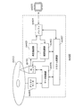
- FIG. 19 is a block diagram illustrating a configuration example of an information reproducing / recording unit that reads and writes information from and on a recording medium that is an optical disk.
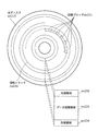
- FIG. 20 is a diagram illustrating a structure example of a recording medium that is an optical disk.
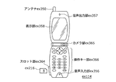
- FIG. 21A is a diagram illustrating an example of a mobile phone.
- FIG. 21B is a block diagram illustrating a configuration example of a mobile phone.
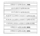
- FIG. 22 is a diagram showing a structure of multiplexed data.
- FIG. 23 is a diagram schematically showing how each stream is multiplexed in the multiplexed data.
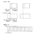
- FIG. 24 is a diagram showing in more detail how the video stream is stored in the PES packet sequence.
- FIG. 25 is a diagram illustrating the structure of TS packets and source packets in multiplexed data.
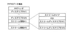
- FIG. 26 is a diagram illustrating a data structure of the PMT.
- FIG. 27 is a diagram showing an internal configuration of multiplexed data information.
- FIG. 28 shows the internal structure of stream attribute information.
- FIG. 29 is a diagram illustrating steps for identifying video data.
- FIG. 30 is a block diagram illustrating a configuration example of an integrated circuit that realizes the moving picture coding method and the moving picture decoding method according to each embodiment.
- FIG. 31 is a diagram showing a configuration for switching the driving frequency.
- FIG. 32 is a diagram illustrating steps for identifying video data and switching between driving frequencies.
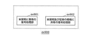
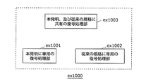
- FIG. 34A is a diagram illustrating an example of a configuration for sharing a module of a signal processing unit.
- FIG. 34B is a diagram illustrating another example of a configuration for sharing a module of a signal processing unit.
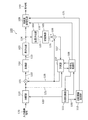
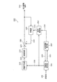
- FIG. 1 is a block diagram of an image coding apparatus 100 using the image coding method according to Embodiment 1 of the present invention.
- the image coding apparatus 100 shown in FIG. 1 divides the input image signal 120 into processing units (blocks), and codes the divided images to generate a code string 140.
- the image encoding device 100 includes a difference unit 101, a transform unit 102, a quantization unit 103, an inverse quantization unit 104, an inverse transform unit 105, an addition unit 106, a prediction unit 107, and an encoding control.
- the dividing unit 110 and the prediction unit 107 may include a memory therein.
- the input image signal 120 is input to the dividing unit 110.
- the dividing unit 110 generates a divided image signal 121 by dividing the input image signal 120 based on the division control signal 129, and outputs the generated divided image signal 121 to the difference unit 101 and the prediction unit 107.
- the division control unit 111 determines a division pattern indicating how the division unit 110 divides the image.
- processing units blocks
- the division control unit 111 determines a division pattern for dividing the input image signal 120 hierarchically from the largest unit of processing units.
- division patterns determined by the division control unit 111 will be described with reference to FIGS. 2A to 2C and FIGS. 3A to 3C.
- the division pattern determined by the division control unit 111 is represented by the depth of the hierarchy (Depth).
- Depth a non-divided block
- the subsequent blocks can be expressed in the same manner.
- FIG. 2B shows an example of the block size and the depth of the hierarchy when the maximum block size is horizontal 64 pixels ⁇ vertical 64 pixels
- FIG. 2C shows the maximum block size of horizontal 128 pixels ⁇ vertical 128 pixels.
- An example of the block size and the depth of the hierarchy is shown.
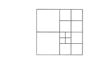
- FIG. 3A shows an example in which the maximum block size is horizontal 64 pixels ⁇ vertical 64 pixels and the minimum block size is horizontal 8 pixels ⁇ vertical 8 pixels, similarly to the case shown in FIG. 2B.
- a block is divided by a method of sequentially specifying whether or not to divide the maximum block size, and if divided, whether or not to divide the sub-block after division.
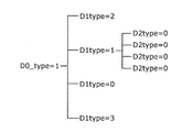
- the block division pattern can be represented by a layer (Dn_type) with respect to the depth of each layer.
- n is the value of the depth of the hierarchy (Depth).
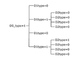
- FIG. 3B shows an example in which the division pattern shown in FIG. 3A is represented by hierarchical division mode information.
- D0_type 1.
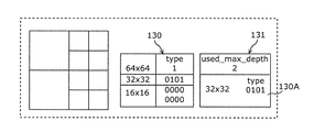
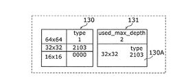
- FIG. 3C shows an example in which the expressions of FIG. 3B are simply summarized. That is, FIG. 3C shows an example in which the hierarchical division mode information for each block size is collectively expressed as division mode information (type).
- the division mode information is binary information indicating that there is division (1) and no division (0), similarly to the hierarchical division mode information. Therefore, the information amount of the division pattern shown in FIG. 3A is 13 bits. Then, the division control unit 111 outputs the division information 130 indicating the division pattern as illustrated in FIG. 3C to the division information description unit 112.
- cost information (encoding cost) necessary for determining the division pattern is calculated as follows, for example.
- the dividing unit 110 generates a divided image signal 121 by dividing the input image signal 120 into a size to be subjected to cost calculation, and outputs the generated divided image signal 121 to the prediction unit 107.
- the prediction unit 107 generates a predicted image signal 128 based on the decoded image signal 127 that has already been encoded and decoded and the prediction mode acquired from the encoding control unit 108.
- the encoding control unit 108 designates one prediction mode out of at least one candidate prediction mode determined in advance to the prediction unit 107.
- the candidate prediction mode is, for example, a mode in which a prediction pixel is generated by extrapolating adjacent pixels in the screen in a predetermined direction, and a pixel having a high correlation with another frame that has already been encoded and decoded This is a mode for generating a prediction pixel using.
- the prediction unit 107 calculates an encoding cost that is a weighted sum of the prediction information and the correlation degree information.
- the prediction information is information necessary for generating the prediction image signal 128, and includes, for example, direction information for extrapolating adjacent pixels in the screen, and relative position information (motion vector information) with another frame.
- the correlation degree information indicates the degree of correlation between the divided image signal 121 and the predicted image signal 128, and is, for example, the sum of absolute differences between the divided image signal 121 and the predicted image signal 128.
- the prediction unit 107 calculates, for example, a value represented by the following (formula 1) called a cost function as an encoding cost.
- the prediction unit 107 calculates the encoding cost for each of all candidate prediction modes, and outputs the predicted image signal 128 predicted in the prediction mode with the lowest encoding cost to the difference unit 101. Also, the prediction unit 107 outputs the prediction mode, prediction information, and encoding cost at that time to the encoding control unit 108.
- the encoding control unit 108 outputs the above-described encoding cost to the division control unit 111 and outputs an encoding control signal 132 including a prediction mode and prediction information to the variable length encoding unit 109.
- RD cost function for example, a Lagrange cost function J represented by (Equation 1) is used.
- R is a code amount used for encoding the difference image (quantized transform coefficient information 124), the prediction mode, and the prediction information
- D is an encoding distortion amount
- ⁇ I a Lagrange multiplier calculated according to the quantization parameter QP used for encoding.
- the encoding control unit 108 selects the prediction mode with the lowest cost function J as the prediction mode used for encoding.
- substitute values may be used.
- the prediction mode information may be used as the code amount R
- the absolute difference sum between the divided image signal 121 and the predicted image signal 128 may be used as the encoding distortion amount.
- FIG. 4 is a flowchart showing the operation of the division control unit 111.
- the maximum block size is horizontal 64 pixels ⁇ vertical 64 pixels
- the minimum block size is horizontal 8 pixels ⁇ vertical 8 pixels
- the division mode information is An example in which two types of division (1) and non-division (0) are shown is shown.
- the division control unit 111 acquires the encoding cost for the divided image signal 121 obtained by dividing the input image signal 120 into 64 horizontal pixels ⁇ 64 vertical pixels by the dividing unit 110. Then, the division control unit 111 sets the acquired encoding cost value as a cost value (D0_cost) for 64 horizontal pixels ⁇ 64 vertical pixels (layer 0) (step S401).
- the division control unit 111 acquires a coding cost for a signal of horizontal 32 pixels ⁇ vertical 32 pixels obtained by further dividing the layer 0. Then, the division control unit 111 sets the obtained encoding cost as a cost value (D1_cost [D1_loop]) for a block of horizontal 32 pixels ⁇ vertical 32 pixels at the position indicated by the counter D1_loop (step S404).
- the processing order of the counter Dn_loop 0 to 3 may be the same on the encoding side and the decoding side. This processing order is, for example, the writing order of the letter Z.
- the division control unit 111 acquires a coding cost for a signal of horizontal 16 pixels ⁇ vertical 16 pixels obtained by further dividing the layer 1. Then, the division control unit 111 sets the obtained division cost as a cost value (D2_cost [D2_loop]) for a block of horizontal 16 pixels ⁇ vertical 16 pixels at the position indicated by the counter D2_loop (step S407).
- D2_cost [D2_loop] a cost value for a block of horizontal 16 pixels ⁇ vertical 16 pixels at the position indicated by the counter D2_loop
- the division control unit 111 acquires a coding cost for a signal of horizontal 8 pixels ⁇ vertical 8 pixels obtained by further dividing the layer 2. Then, the division control unit 111 sets the obtained encoding cost as a cost value (D3_cost [D3_loop]) for a block of horizontal 8 pixels ⁇ vertical 8 pixels at the position indicated by the counter D3_loop (step S410). Then, the division control unit 111 adds D3_cost [D3_loop] to “D3_total_cost” (step S411).
- the division control unit 111 increments the value of the counter D3_loop by 1 and repeats the process when all D3_loops are not completed. Moreover, the division
- the division control unit 111 compares the previously calculated “D3_total_cost” with “D2_cost [D2_loop]” (step S413).
- “D2_cost [D2_loop]” is larger than “D3_total_cost” (YES in step S413)
- the division control unit 111 increments the value of the counter D3_loop by 1 and repeats the process when all the D2_loops are not completed. In addition, when all the processes have been completed, the division control unit 111 proceeds to the next step (step S418).
- the division control unit 111 increments the counter D1_loop by one and performs the repetition process. In addition, when all the processes have been completed, the division control unit 111 proceeds to the next step (step S424).
- the division control unit 111 can determine a division pattern that minimizes the coding cost.
- the method for determining the division pattern is an example, and is not limited thereto.
- the division control unit 111 analyzes the divided image signal 121 obtained from the division unit 110, divides an area where the distribution of the pixel value distribution is high into small blocks, and is large for a portion where the pixel distribution is uniform. It may be divided into blocks. In this way, the circuit scale of the image encoding device 100 can be reduced.
- the division control unit 111 may determine a division pattern by a method determined based on the division result of surrounding blocks that have already been encoded and decoded. As another method for determining a division pattern, the division control unit 111 may determine a division pattern using a division result of a block in another frame that has already been encoded and decoded. These methods will be described in detail in Embodiment 3.
- the division control unit 111 outputs the division information 130 indicating the division pattern determined by the above method to the division information description unit 112.
- the division information 130 is information described in the hierarchical division mode information or the division mode information described above.
- the division information description unit 112 generates division information 131 encoded by the variable length encoding unit 109 from the division information 130.
- the division information description unit 112 acquires layer division mode information (D0type to D2type) for each layer included in the division information 130 (step S501).
- the variable “used_max_depth” is maximum use layer information indicating the maximum use layer.
- the maximum use hierarchy indicates the deepest depth used within the maximum block size. In other words, the maximum use hierarchy is a hierarchy of the deepest block among the blocks included in the division pattern.
- the variable “used_min_depth” is minimum usage layer information indicating the minimum usage layer.
- the minimum use hierarchy shows the shallowest depth used within the maximum block size. In other words, the minimum use hierarchy is a hierarchy of the shallowest block among the blocks included in the division pattern.
- variable length encoding unit 109 a signal encoded by the variable length encoding unit 109 will be described in detail with reference to FIGS. 6A to 6C.
- 6A to 6C are schematic diagrams showing the division information 130 and 131 with respect to the results of different block divisions, respectively.
- the division information 130 includes two 16 ⁇ 16 blocks that are “1” for 64 ⁇ 64 blocks, “0101” for 32 ⁇ 32 blocks, and “1” (divide) for 32 ⁇ 32 blocks. Respectively, “0000” and “0000” are included as the division mode information. Further, the division information description unit 112 determines that “used_max_depth” in this case is “2”. In this case, since the maximum hierarchy resulting from the division is 2, information “0000” and “0000” indicating no division for the 16 ⁇ 16 block is unnecessary. Therefore, the division information description unit 112 determines the division mode information 130A for encoding only the division mode information “0101” for the 32 ⁇ 32 block. Then, the variable length coding unit 109 performs variable length coding processing on the division information 131 including “used_max_depth” and division mode information “0101” for 32 ⁇ 32 blocks.
- the bit length of the division information 130 is represented by 13 bits.
- the division information 131 encoded by the variable length encoding unit 109 is division mode information 4 bits and “used_max_depth”.
- “used_max_depth” is determined from 0 to 3 (in this example, the maximum is layer 3), it can be expressed by 2 bits. That is, in this case, 13-bit information can be expressed by 6 bits.
- the division information 130 is four 16 ⁇ , which is “1” for 64 ⁇ 64 blocks, “1111” for 32 ⁇ 32 blocks, and “1” (divided) for 32 ⁇ 32 blocks.
- Each of the 16 blocks includes “0000”, “0001”, “0000”, and “1100” as the division mode information.
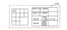
- the division information description unit 112 determines that “used_max_depth” in this case is “3”, and “used_min_depth” is “2”. In this case, since the minimum hierarchy resulting from the division is 2, the division mode information “1111” indicating that there is a division for the 32 ⁇ 32 block is unnecessary.
- the division information description unit 112 determines the division mode information 130A for encoding only four pieces of division mode information for the 16 ⁇ 16 block. Then, the variable length encoding unit 109 performs the division information 131 including “used_max_depth”, “used_min_depth”, and division mode information “0000”, “0001”, “0000”, and “1100” for 16 ⁇ 16 blocks. Variable length coding processing is performed.
- the bit length of the division information 130 is 21 bits.
- the division information 131 encoded by the variable length encoding unit 109 is 16 bits of division mode information, “used_max_depth”, and “used_min_depth”.
- “used_max_depth” is 2 bits as described above.
- “used_mim_depth” is determined from 1 to 3, it can be expressed by 1 to 2 bits. Therefore, in this case, 21-bit information can be expressed by 20 bits.
- the division information 130 is four 16 ⁇ , which is “1” for 64 ⁇ 64 blocks, “1111” for 32 ⁇ 32 blocks, and “1” (divided) for 32 ⁇ 32 blocks.
- Each of the 16 blocks includes “1111”, “1111”, “1111”, and “1111” as the division mode information.
- the division information description unit 112 determines that “used_max_depth” in this case is “3” and “used_min_depth” is “3”. In this case, since the minimum hierarchy as a result of the division is 3, the division mode information “1111” indicating that the division is performed on the 32 ⁇ 32 block and the 16 ⁇ 16 block is unnecessary. Therefore, the variable length encoding unit 109 performs variable length encoding processing on the division information 131 including “used_max_depth” and “used_min_depth”.
- the bit length of the division information 130 is represented by 21 bits.
- the partition information 131 encoded by variable length coding becomes “used_max_depth” and “used_min_depth”.
- used_max_depth is 2 bits as described above
- used_max_depth is 1 to 2 bits. Therefore, in this case, 21-bit information can be expressed by 4 bits.
- variable length coding may be performed using a dynamic probability model such as arithmetic coding. That is, the above-described bit length difference is a reference value, but it can be seen that there is a high possibility that the code amount can be greatly reduced by using the division information description method according to the present embodiment.
- the prediction unit 107 generates the predicted image signal 128 from the decoded image signal 127 that is an already encoded image signal. Then, the prediction unit 107 outputs the generated predicted image signal 128 to the difference unit 101 and the addition unit 106.
- the difference unit 101 generates a difference signal 122 by calculating a difference between the divided image signal 121 that is a signal obtained by dividing the input image signal 120 and the predicted image signal 128, and the generated difference signal 122 is transmitted to the conversion unit 102. Output.
- the conversion unit 102 generates a conversion coefficient 123 by performing a conversion process on the difference signal 122, and outputs the generated conversion coefficient 123 to the quantization unit 103.
- the quantization unit 103 performs quantization processing on the transform coefficient 123 to generate quantized transform coefficient information 124, and the generated quantized transform coefficient information 124 is converted into the variable length encoding unit 109 and the inverse quantization unit 104. Output for.
- the inverse quantization unit 104 generates a transform coefficient 125 by performing inverse quantization processing on the quantized transform coefficient information 124, and outputs the generated transform coefficient 125 to the inverse transform unit 105.
- the inverse transform unit 105 generates a decoded residual image signal 126 by performing an inverse transform process on the transform coefficient 125, and outputs the generated decoded residual image signal 126 to the adder unit 106.
- the addition unit 106 generates a decoded image signal 127 by adding the decoded residual image signal 126 and the predicted image signal 128, and outputs the generated decoded image signal 127 to the prediction unit 107.
- variable length encoding unit 109 performs variable length encoding on the quantization transform coefficient information 124, the encoding control signal 132, and the division information 131, which are signals to be encoded, according to the type of the signal, thereby generating a code string 140. Is generated.
- the above method for determining the division pattern is an example, and the present invention is not limited to this.
- the division result of peripheral blocks that have already been encoded may be used.
- the division result of another frame that has already been encoded may be used. Details of these cases will be described in detail in Embodiment 3.
- the present invention is not limited to this.
- the present invention can be applied even when the image is divided into non-square shapes (16 ⁇ 8, 8 ⁇ 16). Details of this case will be described in detail in Embodiment 5.
- variable length encoding unit 109 when using the arithmetic code in the above-described variable length encoding unit 109, it is used for the arithmetic code based on the shape information of the already encoded block and / or the information on the maximum use layer and / or the minimum use layer.
- the probability model may be switched. This can be expected to further improve the encoding efficiency.
- variable length coding table 109 uses the variable length code table, the information on the maximum use layer and / or the minimum use layer when the reduction width of the division information is large in the bit length calculation described above is used.
- a long bit length may be assigned, and a short bit length may be assigned to information on the maximum use layer and / or the minimum use layer when the reduction width is small.
- the improvement rate of the encoding efficiency by this Embodiment can be raised further.
- the maximum block size is 64 horizontal pixels ⁇ vertical 64 pixels, and the minimum block size is 8 horizontal pixels ⁇ 8 vertical pixels.
- the present invention is not limited to this size and is applicable. can do.
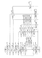
- FIG. 7 is a block diagram of the image decoding apparatus 200 using the division information restoring unit 207 according to the present embodiment.
- An image decoding apparatus 200 illustrated in FIG. 7 includes a variable length decoding unit 201, a decoding control unit 202, an inverse quantization unit 203, an inverse transformation unit 204, a prediction unit 205, an addition unit 206, and a division information restoration unit. 207.
- the prediction unit 205 may include a memory inside.
- the code string 140 is a code string generated by the image coding apparatus 100 according to Embodiment 1 of the present invention. This code string 140 is input to the variable length decoding unit 201.
- the variable length decoding unit 201 decodes the division information included in the code string 140. Specifically, the variable-length decoding unit 201 generates a decoded signal 221 by performing variable-length decoding on the code string 140, and the generated decoded signal 221 is inverted from the division information restoring unit 207 and the decoding control unit 202. The data is output to the quantization unit 203. The variable length decoding unit 201 performs processing in units of division based on the division information 226 obtained by the division information restoration unit 207.
- the inverse quantization unit 203 When the decoded signal 221 is a quantized transform coefficient, the inverse quantization unit 203 generates a transform coefficient 222 by performing inverse quantization on the decoded signal 221.
- the inverse transform unit 204 performs inverse transform on the transform coefficient 222 to generate a decoded residual image signal 223, and outputs the generated decoded residual image signal 223 to the adder 206.
- the decoding control unit 202 uses the division information 226 acquired from the division information restoration unit 207 and the predicted image generation related information 225 as the prediction unit 205. Output for.
- the predicted image generation related information 225 corresponds to the encoding control signal 132 in the image encoding device 100 and includes, for example, a prediction mode and prediction information.
- the prediction unit 205 uses the decoded image signal (output image signal 240) that has already been decoded and the predicted image generation-related information 225 obtained from the decoding control unit 202 to generate the predicted image signal in units of division based on the division information 226. 224 is generated, and the generated predicted image signal 224 is output to the adding unit 206.
- the adder 206 adds the decoded residual image signal 223 and the predicted image signal 224 to generate a decoded image signal (output image signal 240).
- the division information restoration unit 207 determines the division pattern by restoring the division information from the division decoding information to the division information 226.
- the division decoding information corresponds to the division information 131 in the image encoding device 100.
- the division information 226 indicates a division pattern and corresponds to the division information 130 in the first embodiment. The flow of this process will be described in detail with reference to FIG.
- step S802 When “used_max_depth” is 2 (YES in step S802 and NO in step S806), the division information restoring unit 207 changes the counter in the order of 0, 1, 2, and 3 for the depth 1 block, and “D1type” is acquired (steps S807 to S809).
- the division information restoration unit 207 divides the maximum block based on the D1type obtained here (step S810).
- D1type is information for designating a division pattern in, for example, a Z-shaped order for each block obtained by dividing the maximum block into four.
- the division information restoration unit 207 determines a division pattern of the maximum block by determining whether to divide each of the four divided blocks or not based on D1type.
- step S802 If “used_max_depth” is 3 (YES in step S802 and YES in step S806), the division information restoring unit 207 acquires “used_min_depth” (step S811).
- step S812 If “used_min_depth” is 1 (YES in step S812), the division information restoring unit 207 changes the counter in the order of 0, 1, 2, and 3 for the Depth1 block and repeats the process (in steps S821 and S827). By performing the process of the enclosed area, “D1type” of each block of Depth1 is acquired (step S822).
- step S823 If “D1type” is not 0 (NO in step S823), the division information restoring unit 207 changes the counter in the order of 0, 1, 2, and 3 for the depth2 block and repeats the processing (step S824 and step S824). By performing the processing of the area surrounded by step S826, “D2type” of each block of Depth2 is acquired (step S825). Thereafter, the division information restoring unit 207 advances the Depth1 counter by one.
- the division information restoring unit 207 increments the Depth1 counter by one (step S827).
- the division information restoring unit 207 determines the division pattern of the largest block. Determine (step S828).
- the code sequence 140 encoded by the encoding method according to Embodiment 1 can be correctly decoded.
- the present invention can realize an encoding method and a decoding method with high encoding efficiency.
- the division information description unit 112 estimates a predicted division pattern that is a prediction value of the division pattern of the block to be processed, using the already divided block division pattern. Further, the division control unit 111 determines a division pattern of the block to be processed using the estimated prediction division pattern.
- the division information description unit 112 may estimate the division pattern of the processing target block using the division pattern of the block adjacent to the processing target block in the same frame as the processing target block.
- the division pattern of the block to be processed may be estimated using the division pattern of the block included in another frame in terms of time.
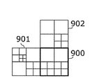
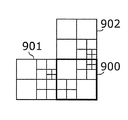
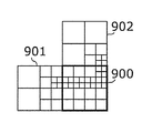
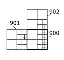
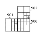
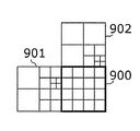
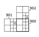
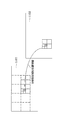
- FIG. 9A to FIG. 9L are schematic diagrams for explaining a case where the division information of the target block is predicted from the division information of the adjacent block.
- FIGS. 9A to 9L are examples in the case where the target block 900 is predicted using the adjacent blocks 901 and 902.
- FIG. 9A, FIG. 9E, and FIG. 9I each show an example of giving priority to the left adjacent block among the cases where the adjacent block in the target block 900 is not used for prediction.
- FIG. 9B, FIG. 9F, and FIG. 9J each show an example in which the adjacent block in the target block 900 is not used for prediction, and the upper adjacent block is prioritized.
- 9C, FIG. 9G, and FIG. 9K each show an example of giving priority to the left adjacent block among the cases where adjacent blocks in the target block 900 are used for prediction.
- FIG. 9D, FIG. 9H, and FIG. 9L show examples when priority is given to the upper adjacent block among the cases where the adjacent block in the target block 900 is used for prediction.
- FIGS. 9A to 9H show an example in the case where there is no restriction on prediction.
- FIG. 10 is a flowchart showing a division pattern prediction procedure according to the present embodiment.
- the division information description unit 112 acquires division information of a processed adjacent block adjacent to the target block (step S1001).
- the division information acquired at this time is the division information of an adjacent block in the same hierarchy as the target block.
- the division information description unit 112 determines that the division information of the target block is “no division” when there is no division information of adjacent blocks in the same layer.
- the division information description unit 112 divides the target block It is predicted not to be performed (step S1003).
- the division information description unit 112 predicts that the target block is divided (step S1004).
- the division information description unit 112 further performs the same processing on the next layer.
- the information indicating which of the upper and left neighbors is to be prioritized may be sent as header information described later, or may be determined in advance on the encoding side and the decoding side.
- the division information description unit 112 uses the division information of the adjacent block included in the target block 900 and does not use the adjacent block. Prediction is performed using only the division information of adjacent blocks included in blocks 901 and 902. In this case, since the division prediction may be performed only by the division information of the upper and left adjacent blocks, the processing speed can be increased.
- the prediction is the same as the processing order, the already determined division information can be used. In this case, since the accuracy of prediction can be further increased, further code amount reduction can be expected.
- it may be determined in advance on the encoding side and the decoding side.
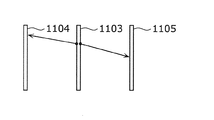
- FIGS. 11A and 11B are schematic diagrams for explaining a case where a division pattern of a target block is predicted from a division pattern of a block of an already encoded and decoded frame.
- FIG. 11A is a schematic diagram illustrating a block division result in the processed frame 1101 that has already been encoded and decoded, and a division prediction result of the target block of the target frame 1102 that is the target of encoding and decoding.
- the division shape relative position information shown in FIG. 11A is information indicating which block of which prediction frame is used for prediction.
- prediction can be performed efficiently by using the division result of either the processed frame 1104 forward or the processed frame 1105 behind the target frame 1103 in terms of time. .
- the division information description unit 112 is based on representative motion vector information among the motion vector information used in the intra-screen prediction calculated by a predetermined method for the division target block (maximum block size).
- the division shape relative position information may be determined. For example, the division information description unit 112 calculates the median of motion vectors of adjacent blocks, and similarly calculates the median of motion vectors for the reference frame. Then, the division information description unit 112 may use a motion vector based on the calculated median as division shape relative position information.
- the division information description unit 112 may use the head motion vector and the reference frame information as it is as the division shape relative position information. In these cases, since it is not necessary to transmit additional information for prediction, the amount of codes can be reduced. Also in this case, the image encoding device 100 may separately transmit the divided shape relative position information. For example, the image encoding device 100 first derives the division information of the division target block. Then, the image encoding device 100 uses the relative position information of the block having the same or closest division information as the division target block from the already encoded frames and the division target block as the division shape relative position information. calculate. Then, the image encoding device 100 may encode and decode the divided shape relative position information, for example, in the same manner as the motion vector information used in the prediction unit 107 in intra prediction.
- FIG. 12A and FIG. 12B description will be given of how to transmit the division information encoded using the predicted division information (FIG. 12A) and how to restore the division information (FIG. 12B). To do.
- the division information description unit 112 calculates a difference between the division pattern and the predicted division pattern, and generates division information 131 including the difference. Details will be described below.
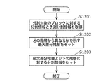
- FIG. 12A is a flowchart for explaining the operation in the division information description unit 112 according to the third embodiment.
- the division information description unit 112 acquires division information and predicted division information (hereinafter, predicted division information) for the target block (step S1201).
- the division information description unit 112 derives the maximum difference layer in the same manner as the process of deriving the maximum use layer (used_max_depth) in the first embodiment (step S1202).
- the maximum difference hierarchy is information indicating from which hierarchy the division information and the predicted division information are different.
- the maximum difference hierarchy is information indicating the highest hierarchy in which the division information and the prediction division information are different.
- this derivation method can be derived by substituting 0 when the predicted division information and the division information are equal, and substituting 1 when the division information is not equal and following the flowchart of FIG.
- the division information description unit 112 sets division information for the hierarchy (step S1203).
- This description method is merely an example, and the description method is not limited to this as long as the prediction method according to the present invention is used.
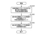
- FIG. 12B is a flowchart for explaining the restoration operation of the division information encoded by the procedure of FIG. 12A.
- the division information restoration unit 207 acquires maximum difference hierarchy information and prediction division information for a block to be divided (step S1204).
- the maximum difference hierarchy information is information indicating the maximum difference hierarchy, and is included in the code string 140 generated by the image encoding device 100.
- the prediction division information is generated by the image decoding device 200 by performing the same processing as the processing performed by the image encoding device 100 described above.
- the division information restoring unit 207 sets the obtained prediction division information in the division information for the layer above the maximum difference layer (information that is equal to the prediction) (step S1205).
- the division information restoring unit 207 can restore the division information of the target block by restoring the division information of the layer below the maximum difference layer (step S1206).
- the division information of the layer below the maximum difference layer is included in the code string 140 generated by the image encoding device 100.
- FIG. 13 is a diagram showing a configuration of the code string 140 in the image coding method according to the present embodiment.
- FIG. 13A shows an encoded signal corresponding to a moving image sequence composed of at least one screen.
- the code string 140 includes sequence data SeqData that is data of the entire screen, and a sequence header SeqHdr that is data common to all the data of the entire screen.
- the sequence header SeqHdr includes division related information SepInfo.
- the division related information SepInfo is a flag for switching, for example, whether the method described in the first embodiment is used or only the division information (Dn_type information) is encoded. Note that the division-related information SepInfo may be information related to the division pattern prediction described in the third embodiment.
- FIG. 13B shows the structure of sequence data SeqData.
- the sequence data SeqData includes a plurality of picture signals PicStr.
- Each picture signal PicStr is an encoded signal corresponding to one screen.
- each picture signal PicStr is a coded signal of a picture.
- FIG. 13C shows the structure of the picture signal PicStr.
- the picture signal PicStr includes picture data PicData that is data of one screen and a picture header PicHdr that is data common to the entire screen.
- the picture header PicHdr may include division related information SepInfo.
- FIG. 13D shows the structure of the picture data PicData.
- the picture data PicData includes a plurality of slice signals SliceStr.
- Each slice signal SliceStr is an encoded signal of a slice that is a set of a plurality of block units.
- FIG. 13E shows the structure of the slice signal SliceStr.
- the slice signal SliceStr includes slice data SliceData that is data of one slice and a slice header SliceHdr that is data common to all data of one slice.
- the slice header SliceHdr may include division related information SepInfo.
- sequence data SeqData includes a plurality of picture signals PicStr
- all the picture headers PicHdr include the division related information SepInfo, instead of all of the picture headers PicHdr include the division related information SepInfo. Good.
- the image decoding apparatus 200 uses the division related information of the target slice as the division related information.
- the division related information SepInfo included in the slice header SliceHdr of another slice is used instead. Thereby, it is possible to suppress an increase in the number of bits due to the repeated inclusion of the division-related information SepInfo.
- the slice data SliceData includes a plurality of maximum block size data LCTB.
- Each maximum block size data LCTB is block unit information of the maximum block size.
- Each maximum block size data LCTB includes a maximum block size header LCTBHdr and a block signal CTBs.
- the block signal CTBs includes a plurality of hierarchical block data CTB.
- the maximum block size header LCTBHdr includes a maximum use layer, a minimum use layer, or a maximum difference layer.
- the maximum block size header LCTBHdr may include all pieces of division information, or each piece of block data CTB may contain division information for the corresponding block.
- FIG. 13 (f) shows the structure of the block data CTB.
- Part of the block data CTB includes a conversion block header TUHdr which is header information of the conversion structure, and a conversion block TUs.
- the transform block TUs can also be divided in the same manner as the blocks (CUs) described above. That is, the present invention may be applied to transform blocks. In this case, conversion of various sizes can be performed, and the amount of codes for transmission of the shape can be reduced.
- the header part and the data part other than the header may be separated and transmitted separately. . In that case, the header part and the data part do not become one bit stream as shown in FIG.
- the corresponding data portion and header portion are only transmitted in different packets. That is, even if the code string 140 is not a single bit stream, the concept is the same as that of the bit stream described with reference to FIG.
- the code string 140 encoded by the above method is decoded by the following procedure.
- the image decoding apparatus 200 acquires the division related information SepInfo included in the sequence header SeqHdr, and holds the acquired division related information.
- the image decoding apparatus 200 acquires the division related information SepInfo included in the picture header PicHdr and updates the held division related information with the acquired division related information.
- the image decoding apparatus 200 when there is no division related information SepInfo, or when there is no part thereof, the image decoding apparatus 200 holds the division related information included in the sequence header SeqHdr as it is.
- the image decoding apparatus 200 acquires the division related information SepInfo included in the slice header SliceHdr and updates the held division related information with the acquired division related information.
- the image decoding apparatus 200 acquires the maximum block size data LCTB and obtains information necessary for division (maximum use layer, minimum use layer or maximum difference layer, and division information) included in the maximum block size header LCTBHdr. get. And the image decoding apparatus 200 determines the subsequent block division
- the image decoding apparatus 200 can correctly decode the code string 140.
- Embodiment 5 In the present embodiment, another modification of the encoding method and decoding method according to the present invention shown in Embodiments 1 to 4 will be described.
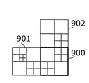
- FIG. 14A to FIG. 14C are schematic diagrams for explaining a dividing method using a plurality of block shapes.
- the division mode information indicated by Dn_type is divided into 0 (no division) and 1 (four divisions) from binary information of 0 (no division) and 1 (division). ) 4 (4 divisions in the horizontal direction) and 3 (2 divisions in the vertical direction). Even in this way, the division information can be encoded with a small code amount by using the method of the present invention.
- the division information description unit 112 describes the block division shape shown in FIG. 14A as division information.
- the block division shape shown in FIG. 14A is expressed by the parameters shown above, it becomes as shown in FIG. 14B.
- each division mode information is set to Dn_type.
- the maximum use hierarchy is 2 by the method of the first embodiment.
- the image decoding apparatus 200 can restore the division shape by decoding the division information of Dn_type and using the same shape rule as that of encoding.
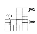
- 15A to 15C are schematic diagrams for explaining that the division information can be further reduced.
- the last division mode information is 1. It can be seen that it is. That is, the division information description unit 112, when the processing target layer is shallower than the maximum use layer and only the last block is divided in the encoding order (division processing order), the division mode information of the last block The division information 131 that does not include is generated.
- the division information description unit 112 removes the information indicating the division pattern of the block from the division information 130 when it is possible to determine whether each block is further divided or not divided using the maximum use hierarchy. Then, the variable length encoding unit 109 encodes the division information 131 after the above information is removed. This processing can further reduce the code amount.
- the division mode information for (vertical 16 pixel block) is (0, 0, 0, 1), respectively. Since both can be decoded as (0, 0, 0) as described above, it is not necessary to encode them. As a result, it is not necessary to encode the two division mode information, and the encoding efficiency can be further improved.
- the division information description unit 112 removes information indicating the division pattern of the block from the division information 130 when it is possible to determine whether each block is further divided or not divided using the minimum use hierarchy. Then, the variable length encoding unit 109 encodes the division information 131 after the above information is removed. Thereby, encoding efficiency can be improved.
- the storage medium may be any medium that can record a program, such as a magnetic disk, an optical disk, a magneto-optical disk, an IC card, and a semiconductor memory.
- the system has an image encoding / decoding device including an image encoding device using an image encoding method and an image decoding device using an image decoding method.
- image encoding / decoding device including an image encoding device using an image encoding method and an image decoding device using an image decoding method.
- Other configurations in the system can be appropriately changed according to circumstances.
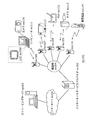
- FIG. 16 is a diagram showing an overall configuration of a content supply system ex100 that realizes a content distribution service.
- the communication service providing area is divided into desired sizes, and base stations ex106, ex107, ex108, ex109, and ex110, which are fixed wireless stations, are installed in each cell.
- the content supply system ex100 includes a computer ex111, a PDA (Personal Digital Assistant) ex112, a camera ex113, a mobile phone ex114, a game machine ex115 via the Internet ex101, the Internet service provider ex102, the telephone network ex104, and the base stations ex106 to ex110. Etc. are connected.
- PDA Personal Digital Assistant
- each device may be directly connected to the telephone network ex104 without going through the base stations ex106 to ex110 which are fixed wireless stations.
- the devices may be directly connected to each other via short-range wireless or the like.
- the camera ex113 is a device that can shoot moving images such as a digital video camera
- the camera ex116 is a device that can shoot still images and movies such as a digital camera.
- the mobile phone ex114 is a GSM (registered trademark) (Global System for Mobile Communications) method, a CDMA (Code Division Multiple Access) method, a W-CDMA (Wideband-Code Division MultipleL), or a W-CDMA (Wideband-Code Division MultipleT method). It may be a system, HSPA (High Speed Packet Access) mobile phone, PHS (Personal Handyphone System), or the like.
- the camera ex113 and the like are connected to the streaming server ex103 through the base station ex109 and the telephone network ex104, thereby enabling live distribution and the like.
- live distribution content that is shot by the user using the camera ex113 (for example, music live video) is encoded as described in the above embodiments (that is, the image encoding of the present invention).
- Function as a device and transmit to the streaming server ex103.
- the streaming server ex103 streams the content data transmitted to the requested client.
- the client include a computer ex111, a PDA ex112, a camera ex113, a mobile phone ex114, a game machine ex115, and the like that can decode the encoded data.
- Each device that receives the distributed data decodes the received data and reproduces it (that is, functions as the image decoding device of the present invention).
- the encoded processing of the captured data may be performed by the camera ex113, the streaming server ex103 that performs the data transmission processing, or may be performed in a shared manner.
- the decryption processing of the distributed data may be performed by the client, the streaming server ex103, or may be performed in a shared manner.
- still images and / or moving image data captured by the camera ex116 may be transmitted to the streaming server ex103 via the computer ex111.
- the encoding process in this case may be performed by any of the camera ex116, the computer ex111, and the streaming server ex103, or may be performed in a shared manner.
- encoding / decoding processes are generally performed by the computer ex111 and the LSI ex500 included in each device.
- the LSI ex500 may be configured as a single chip or a plurality of chips.
- moving image encoding / decoding software is incorporated into some recording media (CD-ROM, flexible disk, hard disk, etc.) that can be read by the computer ex111 and the like, and encoding / decoding processing is performed using the software May be.
- moving image data acquired by the camera may be transmitted.
- the moving image data at this time is data encoded by the LSI ex500 included in the mobile phone ex114.
- the streaming server ex103 may be a plurality of servers or a plurality of computers, and may process, record, and distribute data in a distributed manner.
- the encoded data can be received and reproduced by the client.
- the information transmitted by the user can be received, decrypted and reproduced by the client in real time, and even a user who does not have special rights or facilities can realize personal broadcasting.
- the digital broadcasting system ex200 also includes at least the moving image encoding device (image encoding device) or the moving image decoding according to each of the above embodiments. Any of the devices (image decoding devices) can be incorporated.
- the broadcasting station ex201 multiplexed data obtained by multiplexing music data and the like on video data is transmitted to a communication or satellite ex202 via radio waves.
- This video data is data encoded by the moving image encoding method described in the above embodiments (that is, data encoded by the image encoding apparatus of the present invention).
- the broadcasting satellite ex202 transmits a radio wave for broadcasting, and this radio wave is received by a home antenna ex204 capable of receiving satellite broadcasting.
- the received multiplexed data is decoded and reproduced by an apparatus such as the television (receiver) ex300 or the set top box (STB) ex217 (that is, functions as the image decoding apparatus of the present invention).
- a reader / recorder ex218 that reads and decodes multiplexed data recorded on a recording medium ex215 such as a DVD or a BD, encodes a video signal on the recording medium ex215, and in some cases multiplexes and writes it with a music signal. It is possible to mount the moving picture decoding apparatus or moving picture encoding apparatus shown in the above embodiments. In this case, the reproduced video signal is displayed on the monitor ex219, and the video signal can be reproduced in another device or system using the recording medium ex215 on which the multiplexed data is recorded.
- a moving picture decoding apparatus may be mounted in a set-top box ex217 connected to a cable ex203 for cable television or an antenna ex204 for satellite / terrestrial broadcasting and displayed on the monitor ex219 of the television. At this time, the moving picture decoding apparatus may be incorporated in the television instead of the set top box.
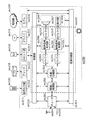
- FIG. 18 is a diagram illustrating a television (receiver) ex300 that uses the video decoding method and the video encoding method described in each of the above embodiments.
- the television ex300 obtains or outputs multiplexed data in which audio data is multiplexed with video data via the antenna ex204 or the cable ex203 that receives the broadcast, and demodulates the received multiplexed data.
- the modulation / demodulation unit ex302 that modulates multiplexed data to be transmitted to the outside, and the demodulated multiplexed data is separated into video data and audio data, or the video data and audio data encoded by the signal processing unit ex306 Is provided with a multiplexing / separating unit ex303.
- the television ex300 decodes each of the audio data and the video data, or encodes the respective information.
- the audio signal processing unit ex304 and the video signal processing unit ex305 (function as the image encoding device or the image decoding device of the present invention).
- the television ex300 includes an interface unit ex317 including an operation input unit ex312 that receives an input of a user operation.
- the television ex300 includes a control unit ex310 that controls each unit in an integrated manner, and a power supply circuit unit ex311 that supplies power to each unit.
- the interface unit ex317 includes a bridge ex313 connected to an external device such as a reader / recorder ex218, a recording unit ex216 such as an SD card, and an external recording such as a hard disk.
- a driver ex315 for connecting to a medium, a modem ex316 for connecting to a telephone network, and the like may be included.
- the recording medium ex216 is capable of electrically recording information by using a nonvolatile / volatile semiconductor memory element to be stored.
- Each part of the television ex300 is connected to each other via a synchronous bus.
- the television ex300 receives a user operation from the remote controller ex220 or the like, and demultiplexes the multiplexed data demodulated by the modulation / demodulation unit ex302 by the multiplexing / demultiplexing unit ex303 based on the control of the control unit ex310 having a CPU or the like. Furthermore, in the television ex300, the separated audio data is decoded by the audio signal processing unit ex304, and the separated video data is decoded by the video signal processing unit ex305 using the decoding method described in the above embodiments.
- the decoded audio signal and video signal are output from the output unit ex309 to the outside.
- these signals may be temporarily stored in the buffers ex318, ex319, etc. so that the audio signal and the video signal are reproduced in synchronization.
- the television ex300 may read multiplexed data from recording media ex215 and ex216 such as a magnetic / optical disk and an SD card, not from broadcasting. Next, a configuration in which the television ex300 encodes an audio signal or a video signal and transmits the signal to the outside or writes it to a recording medium will be described.
- the television ex300 receives a user operation from the remote controller ex220 or the like, and encodes an audio signal with the audio signal processing unit ex304 based on the control of the control unit ex310, and converts the video signal with the video signal processing unit ex305. Encoding is performed using the encoding method described in (1).
- the encoded audio signal and video signal are multiplexed by the multiplexing / demultiplexing unit ex303 and output to the outside. When multiplexing, these signals may be temporarily stored in the buffers ex320 and ex321 so that the audio signal and the video signal are synchronized.
- a plurality of buffers ex318, ex319, ex320, and ex321 may be provided as illustrated, or one or more buffers may be shared. Further, in addition to the illustrated example, data may be stored in the buffer as a buffer material that prevents system overflow and underflow, for example, between the modulation / demodulation unit ex302 and the multiplexing / demultiplexing unit ex303.
- the television ex300 has a configuration for receiving AV input of a microphone and a camera, and performs encoding processing on the data acquired from them. Also good.
- the television ex300 has been described as a configuration that can perform the above-described encoding processing, multiplexing, and external output, but these processing cannot be performed, and only the above-described reception, decoding processing, and external output are possible. It may be a configuration.
- the decoding process or the encoding process may be performed by either the television ex300 or the reader / recorder ex218.
- the reader / recorder ex218 may be shared with each other.
- FIG. 19 shows a configuration of the information reproducing / recording unit ex400 when data is read from or written to an optical disk.
- the information reproducing / recording unit ex400 includes elements ex401, ex402, ex403, ex404, ex405, ex406, and ex407 described below.
- the optical head ex401 irradiates a laser spot on the recording surface of the recording medium ex215 that is an optical disc to write information, and detects information reflected from the recording surface of the recording medium ex215 to read the information.
- the modulation recording unit ex402 electrically drives a semiconductor laser built in the optical head ex401 and modulates the laser beam according to the recording data.
- the reproduction demodulator ex403 amplifies the reproduction signal obtained by electrically detecting the reflected light from the recording surface by the photodetector built in the optical head ex401, separates and demodulates the signal component recorded on the recording medium ex215, and is necessary. To play back information.
- the buffer ex404 temporarily holds information to be recorded on the recording medium ex215 and information reproduced from the recording medium ex215.
- the disk motor ex405 rotates the recording medium ex215.
- the servo control unit ex406 moves the optical head ex401 to a predetermined information track while controlling the rotational drive of the disk motor ex405, and performs a laser spot tracking process.
- the system control unit ex407 controls the entire information reproduction / recording unit ex400.
- the system control unit ex407 uses various types of information held in the buffer ex404, and generates and adds new information as necessary, and the modulation recording unit ex402, the reproduction demodulation unit This is realized by recording / reproducing information through the optical head ex401 while operating the ex403 and the servo control unit ex406 in a coordinated manner.
- the system control unit ex407 is composed of, for example, a microprocessor, and executes these processes by executing a read / write program.
- the optical head ex401 has been described as irradiating a laser spot, but it may be configured to perform higher-density recording using near-field light.
- FIG. 20 shows a schematic diagram of a recording medium ex215 that is an optical disk.
- Guide grooves grooves
- address information indicating the absolute position on the disc is recorded in advance on the information track ex230 by changing the shape of the groove.
- This address information includes information for specifying the position of the recording block ex231 that is a unit for recording data, and the recording block is specified by reproducing the information track ex230 and reading the address information in a recording or reproducing apparatus.
- the recording medium ex215 includes a data recording area ex233, an inner peripheral area ex232, and an outer peripheral area ex234.
- the area used for recording the user data is the data recording area ex233, and the inner circumference area ex232 and the outer circumference area ex234 arranged on the inner circumference or outer circumference of the data recording area ex233 are used for specific purposes other than user data recording. Used.
- the information reproducing / recording unit ex400 reads / writes encoded audio data, video data, or multiplexed data obtained by multiplexing these data with respect to the data recording area ex233 of the recording medium ex215.
- an optical disk such as a single-layer DVD or BD has been described as an example.
- the present invention is not limited to these, and an optical disk having a multilayer structure and capable of recording other than the surface may be used.
- an optical disc with a multi-dimensional recording / reproducing structure such as recording information using light of different wavelengths in the same place on the disc, or recording different layers of information from various angles. It may be.
- the car ex210 having the antenna ex205 can receive data from the satellite ex202 and the like, and the moving image can be reproduced on a display device such as the car navigation ex211 that the car ex210 has.
- the configuration of the car navigation ex211 may be, for example, a configuration in which a GPS receiving unit is added in the configuration illustrated in FIG.
- FIG. 21A is a diagram showing the mobile phone ex114 using the moving picture decoding method and the moving picture encoding method described in the above embodiment.
- the mobile phone ex114 includes an antenna ex350 for transmitting and receiving radio waves to and from the base station ex110, a camera unit ex365 capable of taking video and still images, a video captured by the camera unit ex365, a video received by the antenna ex350, and the like Is provided with a display unit ex358 such as a liquid crystal display for displaying the decrypted data.
- the mobile phone ex114 further includes a main body unit having an operation key unit ex366, an audio output unit ex357 such as a speaker for outputting audio, an audio input unit ex356 such as a microphone for inputting audio,
- a main body unit having an operation key unit ex366, an audio output unit ex357 such as a speaker for outputting audio, an audio input unit ex356 such as a microphone for inputting audio
- an audio input unit ex356 such as a microphone for inputting audio
- the memory unit ex367 for storing encoded data or decoded data such as still images, recorded audio, received video, still images, mails, or the like, or an interface unit with a recording medium for storing data
- a slot portion ex364 is provided.
- the cellular phone ex114 has a power supply circuit ex361, an operation input control unit ex362, and a video signal processing unit ex355 for a main control unit ex360 that comprehensively controls each part of the main body including the display unit ex358 and the operation key unit ex366.
- a camera interface unit ex363, an LCD (Liquid Crystal Display) control unit ex359, a modulation / demodulation unit ex352, a multiplexing / demultiplexing unit ex353, an audio signal processing unit ex354, a slot unit ex364, and a memory unit ex367 are connected to each other via a bus ex370. ing.
- the power supply circuit unit ex361 starts up the mobile phone ex114 in an operable state by supplying power from the battery pack to each unit.
- the mobile phone ex114 converts the audio signal collected by the audio input unit ex356 in the voice call mode into a digital audio signal by the audio signal processing unit ex354 based on the control of the main control unit ex360 having a CPU, a ROM, a RAM, and the like. This is subjected to spectrum spread processing by the modulation / demodulation unit ex352, digital-analog conversion processing and frequency conversion processing by the transmission / reception unit ex351, and then transmitted via the antenna ex350.
- the mobile phone ex114 amplifies the received data received through the antenna ex350 in the voice call mode, performs frequency conversion processing and analog-digital conversion processing, performs spectrum despreading processing in the modulation / demodulation unit ex352, and performs voice signal processing unit After converting to an analog audio signal at ex354, this is output from the audio output unit ex357.
- the text data of the e-mail input by operating the operation key unit ex366 of the main unit is sent to the main control unit ex360 via the operation input control unit ex362.
- the main control unit ex360 performs spread spectrum processing on the text data in the modulation / demodulation unit ex352, performs digital analog conversion processing and frequency conversion processing in the transmission / reception unit ex351, and then transmits the text data to the base station ex110 via the antenna ex350.
- almost the reverse process is performed on the received data and output to the display unit ex358.
- the video signal processing unit ex355 compresses the video signal supplied from the camera unit ex365 by the moving image encoding method described in each of the above embodiments. Encode (that is, function as an image encoding apparatus of the present invention), and send the encoded video data to the multiplexing / demultiplexing unit ex353.
- the audio signal processing unit ex354 encodes the audio signal picked up by the audio input unit ex356 while the camera unit ex365 images a video, a still image, and the like, and sends the encoded audio data to the multiplexing / demultiplexing unit ex353. To do.
- the multiplexing / demultiplexing unit ex353 multiplexes the encoded video data supplied from the video signal processing unit ex355 and the encoded audio data supplied from the audio signal processing unit ex354 by a predetermined method, and is obtained as a result.
- the multiplexed data is subjected to spread spectrum processing by the modulation / demodulation unit (modulation / demodulation circuit unit) ex352, digital-analog conversion processing and frequency conversion processing by the transmission / reception unit ex351, and then transmitted through the antenna ex350.
- the multiplexing / separating unit ex353 separates the multiplexed data into a video data bit stream and an audio data bit stream, and performs video signal processing on the video data encoded via the synchronization bus ex370.
- the encoded audio data is supplied to the audio signal processing unit ex354 while being supplied to the unit ex355.
- the video signal processing unit ex355 decodes the video signal by decoding using the video decoding method corresponding to the video encoding method shown in each of the above embodiments (that is, functions as the image decoding device of the present invention). For example, video and still images included in the moving image file linked to the home page are displayed from the display unit ex358 via the LCD control unit ex359.
- the audio signal processing unit ex354 decodes the audio signal, and the audio output unit ex357 outputs the audio.
- the terminal such as the mobile phone ex114 is referred to as a transmitting terminal having only an encoder and a receiving terminal having only a decoder.
- a transmitting terminal having only an encoder
- a receiving terminal having only a decoder.
- multiplexed data in which music data or the like is multiplexed with video data is received and transmitted.
- data in which character data or the like related to video is multiplexed It may be video data itself instead of multiplexed data.
- the moving picture encoding method or the moving picture decoding method shown in each of the above embodiments can be used in any of the above-described devices / systems. The described effect can be obtained.
- multiplexed data obtained by multiplexing audio data or the like with video data is configured to include identification information indicating which standard the video data conforms to.
- identification information indicating which standard the video data conforms to.
- FIG. 22 is a diagram showing a structure of multiplexed data.
- the multiplexed data is obtained by multiplexing one or more of a video stream, an audio stream, a presentation graphics stream (PG), and an interactive graphics stream.
- the video stream indicates the main video and sub-video of the movie
- the audio stream (IG) indicates the main audio portion of the movie and the sub-audio mixed with the main audio
- the presentation graphics stream indicates the subtitles of the movie.
- the main video indicates a normal video displayed on the screen
- the sub-video is a video displayed on a small screen in the main video.
- the interactive graphics stream indicates an interactive screen created by arranging GUI components on the screen.
- the video stream is encoded by the moving image encoding method or apparatus shown in the above embodiments, or the moving image encoding method or apparatus conforming to the conventional standards such as MPEG-2, MPEG4-AVC, and VC-1. ing.
- the audio stream is encoded by a method such as Dolby AC-3, Dolby Digital Plus, MLP, DTS, DTS-HD, or linear PCM.
- Each stream included in the multiplexed data is identified by PID. For example, 0x1011 for video streams used for movie images, 0x1100 to 0x111F for audio streams, 0x1200 to 0x121F for presentation graphics, 0x1400 to 0x141F for interactive graphics streams, 0x1B00 to 0x1B1F are assigned to video streams used for sub-pictures, and 0x1A00 to 0x1A1F are assigned to audio streams used for sub-audio mixed with the main audio.
- FIG. 23 is a diagram schematically showing how multiplexed data is multiplexed.
- a video stream ex235 composed of a plurality of video frames and an audio stream ex238 composed of a plurality of audio frames are converted into PES packet sequences ex236 and ex239, respectively, and converted into TS packets ex237 and ex240.
- the data of the presentation graphics stream ex241 and interactive graphics ex244 are converted into PES packet sequences ex242 and ex245, respectively, and further converted into TS packets ex243 and ex246.
- the multiplexed data ex247 is configured by multiplexing these TS packets into one stream.
- FIG. 24 shows in more detail how the video stream is stored in the PES packet sequence.
- the first row in FIG. 24 shows a video frame sequence of the video stream.
- the second level shows a PES packet sequence.
- a plurality of Video Presentation Units in a video stream are divided into pictures, B pictures, and P pictures, and are stored in the payload of the PES packet.
- Each PES packet has a PES header, and a PTS (Presentation Time-Stamp) that is a display time of a picture and a DTS (Decoding Time-Stamp) that is a decoding time of a picture are stored in the PES header.
- PTS Presentation Time-Stamp
- DTS Decoding Time-Stamp
- FIG. 25 shows the format of the TS packet that is finally written in the multiplexed data.
- the TS packet is a 188-byte fixed-length packet composed of a 4-byte TS header having information such as a PID for identifying a stream and a 184-byte TS payload for storing data.
- the PES packet is divided and stored in the TS payload.
- a 4-byte TP_Extra_Header is added to a TS packet, forms a 192-byte source packet, and is written in multiplexed data.
- TP_Extra_Header information such as ATS (Arrival_Time_Stamp) is described.
- ATS indicates the transfer start time of the TS packet to the PID filter of the decoder.
- source packets are arranged in the multiplexed data, and the number incremented from the head of the multiplexed data is called SPN (source packet number).
- TS packets included in the multiplexed data include PAT (Program Association Table), PMT (Program Map Table), PCR (Program Clock Reference), and the like in addition to each stream such as video / audio / caption.
- PAT indicates what the PID of the PMT used in the multiplexed data is, and the PID of the PAT itself is registered as 0.
- the PMT has the PID of each stream such as video / audio / subtitles included in the multiplexed data and the attribute information of the stream corresponding to each PID, and has various descriptors related to the multiplexed data.
- the descriptor includes copy control information for instructing permission / non-permission of copying of multiplexed data.
- the PCR corresponds to the ATS in which the PCR packet is transferred to the decoder. Contains STC time information.
- FIG. 26 is a diagram for explaining the data structure of the PMT in detail.
- a PMT header describing the length of data included in the PMT is arranged at the head of the PMT.
- a plurality of descriptors related to multiplexed data are arranged.
- the copy control information and the like are described as descriptors.
- a plurality of pieces of stream information regarding each stream included in the multiplexed data are arranged.
- the stream information includes a stream descriptor in which a stream type, a stream PID, and stream attribute information (frame rate, aspect ratio, etc.) are described to identify a compression codec of the stream.
- the multiplexed data is recorded together with the multiplexed data information file.
- the multiplexed data information file is management information of multiplexed data, has a one-to-one correspondence with the multiplexed data, and includes multiplexed data information, stream attribute information, and an entry map.
- the multiplexed data information is composed of a system rate, a reproduction start time, and a reproduction end time.
- the system rate indicates a maximum transfer rate of multiplexed data to a PID filter of a system target decoder described later.
- the ATS interval included in the multiplexed data is set to be equal to or less than the system rate.
- the playback start time is the PTS of the first video frame of the multiplexed data
- the playback end time is set by adding the playback interval for one frame to the PTS of the video frame at the end of the multiplexed data.
- attribute information about each stream included in the multiplexed data is registered for each PID.
- the attribute information has different information for each video stream, audio stream, presentation graphics stream, and interactive graphics stream.
- the video stream attribute information includes the compression codec used to compress the video stream, the resolution of the individual picture data constituting the video stream, the aspect ratio, and the frame rate. It has information such as how much it is.
- the audio stream attribute information includes the compression codec used to compress the audio stream, the number of channels included in the audio stream, the language supported, and the sampling frequency. With information. These pieces of information are used for initialization of the decoder before the player reproduces it.
- the stream type included in the PMT is used.
- video stream attribute information included in the multiplexed data information is used.
- the video encoding shown in each of the above embodiments for the stream type or video stream attribute information included in the PMT.
- FIG. 29 shows steps of the moving picture decoding method according to the present embodiment.
- step exS100 the stream type included in the PMT or the video stream attribute information included in the multiplexed data information is acquired from the multiplexed data.
- step exS101 it is determined whether or not the stream type or the video stream attribute information indicates multiplexed data generated by the moving picture encoding method or apparatus described in the above embodiments. To do.
- step exS102 each of the above embodiments.
- Decoding is performed by the moving picture decoding method shown in the form.
- the conventional information Decoding is performed by a moving image decoding method compliant with the standard.
- FIG. 30 shows a configuration of an LSI ex500 that is made into one chip.
- the LSI ex500 includes elements ex501, ex502, ex503, ex504, ex505, ex506, ex507, ex508, and ex509 described below, and each element is connected via a bus ex510.
- the power supply circuit unit ex505 starts up to an operable state by supplying power to each unit when the power supply is in an on state.
- the LSI ex500 uses the AV I / O ex509 to perform the microphone ex117 and the camera ex113 based on the control of the control unit ex501 including the CPU ex502, the memory controller ex503, the stream controller ex504, the drive frequency control unit ex512, and the like.
- the AV signal is input from the The input AV signal is temporarily stored in an external memory ex511 such as SDRAM.
- the accumulated data is divided into a plurality of times as appropriate according to the processing amount and the processing speed and sent to the signal processing unit ex507, and the signal processing unit ex507 encodes an audio signal and / or video. Signal encoding is performed.
- the encoding process of the video signal is the encoding process described in the above embodiments.
- the signal processing unit ex507 further performs processing such as multiplexing the encoded audio data and the encoded video data according to circumstances, and outputs the result from the stream I / Oex 506 to the outside.
- the output multiplexed data is transmitted to the base station ex107 or written to the recording medium ex215. It should be noted that data should be temporarily stored in the buffer ex508 so as to be synchronized when multiplexing.
- the memory ex511 has been described as an external configuration of the LSI ex500.
- a configuration included in the LSI ex500 may be used.
- the number of buffers ex508 is not limited to one, and a plurality of buffers may be provided.
- the LSI ex500 may be made into one chip or a plurality of chips.
- control unit ex501 includes the CPU ex502, the memory controller ex503, the stream controller ex504, the drive frequency control unit ex512, and the like, but the configuration of the control unit ex501 is not limited to this configuration.
- the signal processing unit ex507 may further include a CPU.
- the CPU ex502 may be configured to include a signal processing unit ex507 or, for example, an audio signal processing unit that is a part of the signal processing unit ex507.
- the control unit ex501 is configured to include a signal processing unit ex507 or a CPU ex502 having a part thereof.
- LSI LSI
- IC system LSI
- super LSI ultra LSI depending on the degree of integration
- the method of circuit integration is not limited to LSI, and implementation with a dedicated circuit or a general-purpose processor is also possible.
- An FPGA Field Programmable Gate Array
- a reconfigurable processor that can reconfigure the connection and setting of circuit cells inside the LSI may be used.
- FIG. 31 shows a configuration ex800 in the present embodiment.
- the drive frequency switching unit ex803 sets the drive frequency high when the video data is generated by the moving image encoding method or apparatus described in the above embodiments.
- the decoding processing unit ex801 that executes the moving picture decoding method described in each of the above embodiments is instructed to decode the video data.
- the video data is video data compliant with the conventional standard, compared to the case where the video data is generated by the moving picture encoding method or apparatus shown in the above embodiments, Set the drive frequency low. Then, it instructs the decoding processing unit ex802 compliant with the conventional standard to decode the video data.
- the drive frequency switching unit ex803 includes the CPU ex502 and the drive frequency control unit ex512 in FIG.
- the decoding processing unit ex801 that executes the moving picture decoding method described in each of the above embodiments and the decoding processing unit ex802 that conforms to the conventional standard correspond to the signal processing unit ex507 in FIG.
- the CPU ex502 identifies which standard the video data conforms to.
- the drive frequency control unit ex512 sets the drive frequency.
- the signal processing unit ex507 decodes the video data.
- the identification of the video data for example, it is conceivable to use the identification information described in the seventh embodiment.
- the identification information is not limited to that described in Embodiment 7, and any information that can identify which standard the video data conforms to may be used. For example, it is possible to identify which standard the video data conforms to based on an external signal that identifies whether the video data is used for a television or a disk. In some cases, identification may be performed based on such an external signal. In addition, the selection of the driving frequency in the CPU ex502 may be performed based on, for example, a lookup table in which video data standards and driving frequencies are associated with each other as shown in FIG. The look-up table is stored in the buffer ex508 or the internal memory of the LSI, and the CPU ex502 can select the drive frequency by referring to this look-up table.
- FIG. 32 shows steps for executing the method of the present embodiment.
- the signal processing unit ex507 acquires identification information from the multiplexed data.
- the CPU ex502 identifies whether the video data is generated by the encoding method or apparatus described in each of the above embodiments based on the identification information.
- the CPU ex502 sends a signal for setting the drive frequency high to the drive frequency control unit ex512. Then, the drive frequency control unit ex512 sets a high drive frequency.
- step exS203 the CPU ex502 drives a signal for setting the drive frequency low. This is sent to the frequency control unit ex512. Then, in the drive frequency control unit ex512, the drive frequency is set to be lower than that in the case where the video data is generated by the encoding method or apparatus described in the above embodiments.
- the power saving effect can be further enhanced by changing the voltage applied to the LSI ex500 or the device including the LSI ex500 in conjunction with the switching of the driving frequency.
- the drive frequency is set to be low, it is conceivable that the voltage applied to the LSI ex500 or the device including the LSI ex500 is set low as compared with the case where the drive frequency is set high.
- the setting method of the driving frequency may be set to a high driving frequency when the processing amount at the time of decoding is large, and to a low driving frequency when the processing amount at the time of decoding is small. It is not limited to the method.
- the amount of processing for decoding video data compliant with the MPEG4-AVC standard is larger than the amount of processing for decoding video data generated by the moving picture encoding method or apparatus described in the above embodiments. It is conceivable that the setting of the driving frequency is reversed to that in the case described above.
- the method for setting the drive frequency is not limited to the configuration in which the drive frequency is lowered.
- the voltage applied to the LSI ex500 or the apparatus including the LSI ex500 is set high.
- the video data conforms to the conventional standards such as MPEG-2, MPEG4-AVC, VC-1, etc.
- the identification information indicates that the video data is generated by the moving image encoding method or apparatus described in each of the above embodiments, the driving of the CPU ex502 is stopped.
- the CPU ex502 is temporarily stopped because there is enough processing. Is also possible. Even when the identification information indicates that the video data is generated by the moving image encoding method or apparatus described in each of the above embodiments, if there is enough processing, the CPU ex502 is temporarily driven. It can also be stopped. In this case, it is conceivable to set the stop time shorter than in the case where the video data conforms to the conventional standards such as MPEG-2, MPEG4-AVC, and VC-1.
- a plurality of video data that conforms to different standards may be input to the above-described devices and systems such as a television and a mobile phone.
- the signal processing unit ex507 of the LSI ex500 needs to support a plurality of standards in order to be able to decode even when a plurality of video data complying with different standards is input.
- the signal processing unit ex507 corresponding to each standard is used individually, there is a problem that the circuit scale of the LSI ex500 increases and the cost increases.
- a decoding processing unit for executing the moving picture decoding method shown in each of the above embodiments and a decoding conforming to a standard such as MPEG-2, MPEG4-AVC, or VC-1
- the processing unit is partly shared.
- An example of this configuration is shown as ex900 in FIG. 34A.
- the moving picture decoding method shown in each of the above embodiments and the moving picture decoding method compliant with the MPEG4-AVC standard are processed in processes such as entropy coding, inverse quantization, deblocking filter, and motion compensation. Some contents are common.
- the decoding processing unit ex902 corresponding to the MPEG4-AVC standard is shared, and for other processing contents unique to the present invention that do not correspond to the MPEG4-AVC standard, the dedicated decoding processing unit ex901 is used. Configuration is conceivable. In particular, since the present invention has a feature in the division processing, for example, the dedicated decoding processing unit ex901 is used for the division processing, and other entropy coding, inverse quantization, deblocking filter, motion, and the like are used. It is conceivable to share the decoding processing unit for any or all of the compensation processes.
- the decoding processing unit for executing the moving picture decoding method described in each of the above embodiments is shared, and the processing content specific to the MPEG4-AVC standard As for, a configuration using a dedicated decoding processing unit may be used.
- ex1000 in FIG. 34B shows another example in which processing is partially shared.
- a dedicated decoding processing unit ex1001 corresponding to processing content specific to the present invention
- a dedicated decoding processing unit ex1002 corresponding to processing content specific to other conventional standards
- a moving picture decoding method of the present invention A common decoding processing unit ex1003 corresponding to processing contents common to other conventional video decoding methods is used.
- the dedicated decoding processing units ex1001 and ex1002 are not necessarily specialized in the processing content specific to the present invention or other conventional standards, and may be capable of executing other general-purpose processing.
- the configuration of the present embodiment can be implemented by LSI ex500.
- the circuit scale of the LSI is reduced, and the cost is reduced. It is possible to reduce.
- the image encoding method and image decoding method according to the present invention enable efficient description and restoration of a block division method that cannot be handled by the conventional variable length encoding and decoding method.
- the image encoding method and the image decoding method have an effect that the amount of codes can be greatly reduced, and thus can be used for various purposes such as storage, transmission, and communication.
- the present invention can be used for high-resolution information display devices or imaging devices such as televisions, digital video recorders, car navigation systems, mobile phones, digital cameras, and digital video cameras.
Abstract
Priority Applications (17)
| Application Number | Priority Date | Filing Date | Title |
|---|---|---|---|
| BR112013004425-0A BR112013004425B1 (pt) | 2010-12-06 | 2011-12-05 | método de codificação de imagem, método de decodificação de imagem, dispositivo de codificação de imagem e dispositivo de decodificação de imagem |
| US13/817,836 US9838723B2 (en) | 2010-12-06 | 2011-12-05 | Image coding method and image coding device for partitioning an image into processing units and coding the partitioned image to generate a code sequence |
| CN201180038021.7A CN103053158B (zh) | 2010-12-06 | 2011-12-05 | 图像编码方法及图像编码装置 |
| EP11846191.2A EP2651128B1 (fr) | 2010-12-06 | 2011-12-05 | Procédé de codage d'image, procédé de décodage d'image, dispositif de codage d'image et dispositif de décodage d'image |
| JP2012547711A JP5744060B2 (ja) | 2010-12-06 | 2011-12-05 | 画像符号化方法及び画像符号化装置 |
| PL11846191T PL2651128T3 (pl) | 2010-12-06 | 2011-12-05 | Sposób dekodowania obrazu, sposób kodowania obrazu, urządzenie dekodujące obraz oraz urządzenie kodujące obraz |
| RU2013108103/07A RU2593382C2 (ru) | 2010-12-06 | 2011-12-05 | Способ кодирования изображений, способ декодирования изображений, устройство кодирования изображений и устройство декодирования изображений |
| PL18169910T PL3389277T3 (pl) | 2010-12-06 | 2011-12-05 | Sposób dekodowania obrazu, urządzenie do dekodowania obrazu |
| MX2013002086A MX2013002086A (es) | 2010-12-06 | 2011-12-05 | Metodo de codificacion de imagen, metodo de decodificacion de imagen, dispositivo de codificacion de imagen y dispositivo de decodificacion de imagen. |
| KR1020137003126A KR101941298B1 (ko) | 2010-12-06 | 2011-12-05 | 화상 부호화 방법, 화상 복호 방법, 화상 부호화 장치 및 화상 복호 장치 |
| EP18169910.9A EP3389277B1 (fr) | 2010-12-06 | 2011-12-05 | Procédé de décodage d'image, et dispositif de décodage d'image |
| CA2808376A CA2808376C (fr) | 2010-12-06 | 2011-12-05 | Procede de codage d'image, procede de decodage d'image, dispositif de codage d'image et dispositif de decodage d'image |
| ES11846191.2T ES2691743T3 (es) | 2010-12-06 | 2011-12-05 | Método de codificación de imágenes, método de decodificación de imágenes, dispositivo de codificación de imágenes y dispositivo de decodificación de imágenes |
| US15/264,749 US9894389B2 (en) | 2010-12-06 | 2016-09-14 | Image coding method and image coding device for partitioning an image into processing units and coding the partitioned image to generate a code sequence |
| US15/857,856 US10123054B2 (en) | 2010-12-06 | 2017-12-29 | Image coding method and image coding device for partitioning an image into processing units and coding the partitioned image to generate a code sequence |
| US16/150,507 US10390051B2 (en) | 2010-12-06 | 2018-10-03 | Image coding method and image coding device for partitioning an image into processing units and coding the partitioned image to generate a code sequence |
| US16/456,407 US10659820B2 (en) | 2010-12-06 | 2019-06-28 | Image coding method and image coding device for partitioning an image into processing units and coding the partitioned image to generate a code sequence |
Applications Claiming Priority (2)
| Application Number | Priority Date | Filing Date | Title |
|---|---|---|---|
| US41996510P | 2010-12-06 | 2010-12-06 | |
| US61/419,965 | 2010-12-06 |
Related Child Applications (2)
| Application Number | Title | Priority Date | Filing Date |
|---|---|---|---|
| US13/817,836 A-371-Of-International US9838723B2 (en) | 2010-12-06 | 2011-12-05 | Image coding method and image coding device for partitioning an image into processing units and coding the partitioned image to generate a code sequence |
| US15/264,749 Continuation US9894389B2 (en) | 2010-12-06 | 2016-09-14 | Image coding method and image coding device for partitioning an image into processing units and coding the partitioned image to generate a code sequence |
Publications (1)
| Publication Number | Publication Date |
|---|---|
| WO2012077332A1 true WO2012077332A1 (fr) | 2012-06-14 |
Family
ID=46206843
Family Applications (1)
| Application Number | Title | Priority Date | Filing Date |
|---|---|---|---|
| PCT/JP2011/006807 WO2012077332A1 (fr) | 2010-12-06 | 2011-12-05 | Procédé de codage d'image, procédé de décodage d'image, dispositif de codage d'image et dispositif de décodage d'image |
Country Status (12)
| Country | Link |
|---|---|
| US (5) | US9838723B2 (fr) |
| EP (2) | EP2651128B1 (fr) |
| JP (3) | JP5744060B2 (fr) |
| KR (1) | KR101941298B1 (fr) |
| CN (2) | CN107105300B (fr) |
| BR (1) | BR112013004425B1 (fr) |
| CA (1) | CA2808376C (fr) |
| ES (2) | ES2691743T3 (fr) |
| MX (1) | MX2013002086A (fr) |
| PL (2) | PL3389277T3 (fr) |
| RU (1) | RU2593382C2 (fr) |
| WO (1) | WO2012077332A1 (fr) |
Cited By (7)
| Publication number | Priority date | Publication date | Assignee | Title |
|---|---|---|---|---|
| WO2014045515A1 (fr) * | 2012-09-18 | 2014-03-27 | 日本電気株式会社 | Dispositif de codage vidéo, procédé de codage vidéo et programme de codage vidéo |
| JP2015526976A (ja) * | 2012-07-09 | 2015-09-10 | オランジュ | 現在ブロックの分割を予測することによるビデオ符号化方法、復号化方法、対応する符号化及び復号化装置、並びにコンピュータプログラム |
| JP2017005629A (ja) * | 2015-06-15 | 2017-01-05 | 日本放送協会 | 符号化装置、復号装置及びプログラム |
| JP2017175191A (ja) * | 2016-03-18 | 2017-09-28 | 富士通株式会社 | 符号化処理プログラム、符号化処理方法及び符号化処理装置 |
| JP2017208768A (ja) * | 2016-05-20 | 2017-11-24 | 日本電信電話株式会社 | 映像符号化装置、ブロック構造決定方法及びコンピュータプログラム |
| JP2018093416A (ja) * | 2016-12-06 | 2018-06-14 | 株式会社Jvcケンウッド | 画像符号化装置、画像符号化方法及び画像符号化プログラム、並びに画像復号化装置、画像復号化方法及び画像復号化プログラム |
| JP2022095851A (ja) * | 2020-12-18 | 2022-06-28 | 株式会社Jvcケンウッド | 画像符号化装置、画像符号化方法及び画像符号化プログラム、並びに画像復号化装置、画像復号化方法及び画像復号化プログラム |
Families Citing this family (18)
| Publication number | Priority date | Publication date | Assignee | Title |
|---|---|---|---|---|
| JP2012023597A (ja) * | 2010-07-15 | 2012-02-02 | Sony Corp | 画像処理装置及び画像処理方法 |
| US9202289B2 (en) * | 2010-09-30 | 2015-12-01 | Electronics And Telecommunications Research Institute | Method for coding and decoding target block partition information using information about neighboring blocks |
| EP2651128B1 (fr) | 2010-12-06 | 2018-07-25 | Sun Patent Trust | Procédé de codage d'image, procédé de décodage d'image, dispositif de codage d'image et dispositif de décodage d'image |
| US9154799B2 (en) | 2011-04-07 | 2015-10-06 | Google Inc. | Encoding and decoding motion via image segmentation |
| WO2013089700A1 (fr) * | 2011-12-14 | 2013-06-20 | Intel Corporation | Procédés, systèmes et produits programmes d'ordinateur permettant d'évaluer un candidat de macrobloc pour une conversion vers un macrobloc sauté |
| US9262670B2 (en) | 2012-02-10 | 2016-02-16 | Google Inc. | Adaptive region of interest |
| KR102088383B1 (ko) * | 2013-03-15 | 2020-03-12 | 삼성전자주식회사 | 비디오의 부호화 방법 및 장치, 비디오의 복호화 방법 및 장치 |
| CN110087089B (zh) | 2013-11-27 | 2023-03-10 | 寰发股份有限公司 | 用于颜色视频数据的视频编解码方法 |
| WO2015135175A1 (fr) * | 2014-03-13 | 2015-09-17 | Mediatek Singapore Pte. Ltd. | Procédé simplifié de partitionnement de bloc basé sur la profondeur |
| US9392272B1 (en) | 2014-06-02 | 2016-07-12 | Google Inc. | Video coding using adaptive source variance based partitioning |
| US20170164003A1 (en) * | 2014-06-26 | 2017-06-08 | Kt Corporation | Multiview video signal processing method and apparatus |
| US9578324B1 (en) | 2014-06-27 | 2017-02-21 | Google Inc. | Video coding using statistical-based spatially differentiated partitioning |
| US20180091810A1 (en) * | 2015-03-23 | 2018-03-29 | Lg Electronics Inc. | Method for processing video signal and device therefor |
| WO2017008263A1 (fr) * | 2015-07-15 | 2017-01-19 | Mediatek Singapore Pte. Ltd. | Structure de partitionnement conditionnel de bloc d'arbre binaire |
| US9942548B2 (en) * | 2016-02-16 | 2018-04-10 | Google Llc | Entropy coding transform partitioning information |
| US10511858B2 (en) | 2016-07-13 | 2019-12-17 | Ati Technologies Ulc | Bit packing for delta color compression |
| US10609423B2 (en) * | 2016-09-07 | 2020-03-31 | Qualcomm Incorporated | Tree-type coding for video coding |
| WO2023075568A1 (fr) * | 2021-11-01 | 2023-05-04 | 엘지전자 주식회사 | Procédé et dispositif de codage/décodage de fonctionnalités sur la base d'une référence inter-canaux de structure de codage, support d'enregistrement dans lequel un flux binaire est stocké, et procédé de transmission de flux binaire |
Citations (1)
| Publication number | Priority date | Publication date | Assignee | Title |
|---|---|---|---|---|
| WO2012005099A1 (fr) * | 2010-07-09 | 2012-01-12 | ソニー株式会社 | Dispositif de traitement d'image, et procédé de traitement d'image |
Family Cites Families (31)
| Publication number | Priority date | Publication date | Assignee | Title |
|---|---|---|---|---|
| WO1997017797A2 (fr) * | 1995-10-25 | 1997-05-15 | Sarnoff Corporation | Appareil et procede d'evaluation du mouvement de blocs de longueur variable fondee sur une quadripartition |
| JP2000134622A (ja) * | 1998-10-23 | 2000-05-12 | Matsushita Electric Ind Co Ltd | データ処理装置 |
| DE19860531C1 (de) | 1998-12-30 | 2000-08-10 | Univ Muenchen Tech | Verfahren zur Übertragung codierter digitaler Signale |
| CN1170437C (zh) * | 1999-06-08 | 2004-10-06 | 松下电器产业株式会社 | 图像信号混洗装置和方法 |
| KR100371513B1 (ko) * | 1999-12-06 | 2003-02-07 | 주식회사 팬택앤큐리텔 | 계층적 동영상 트리구조에서의 에지에 저장하는 키프레임의 충실도를 이용한 효율적인 동영상 요약 및 브라우징 장치 및 방법 |
| US6795584B2 (en) * | 2002-10-03 | 2004-09-21 | Nokia Corporation | Context-based adaptive variable length coding for adaptive block transforms |
| DE602004011234T2 (de) * | 2004-11-19 | 2009-01-02 | Telefonaktiebolaget Lm Ericsson (Publ) | Verfahren und Vorrichtung zur Erzeugung dreidimensionaler Bilder |
| CN1285215C (zh) * | 2004-12-31 | 2006-11-15 | 大唐微电子技术有限公司 | 视频通信系统的帧率调节方法 |
| MX2008001307A (es) * | 2005-07-29 | 2008-03-19 | Lg Electronics Inc | Metodo para la senalizacion de informacion de division. |
| KR101365570B1 (ko) | 2007-01-18 | 2014-02-21 | 삼성전자주식회사 | 인트라 예측 부호화, 복호화 방법 및 장치 |
| JP4321628B2 (ja) * | 2007-05-31 | 2009-08-26 | ソニー株式会社 | 記憶装置、記憶方法および記憶プログラム、ならびに、データ処理装置、データ処理方法およびデータ処理プログラム |
| CN101605251B (zh) * | 2009-07-24 | 2011-05-11 | 清华大学 | 无线视频传输方法和系统 |
| KR101624649B1 (ko) * | 2009-08-14 | 2016-05-26 | 삼성전자주식회사 | 계층적인 부호화 블록 패턴 정보를 이용한 비디오 부호화 방법 및 장치, 비디오 복호화 방법 및 장치 |
| KR101487686B1 (ko) * | 2009-08-14 | 2015-01-30 | 삼성전자주식회사 | 비디오 부호화 방법 및 장치, 비디오 복호화 방법 및 장치 |
| KR101456498B1 (ko) * | 2009-08-14 | 2014-10-31 | 삼성전자주식회사 | 계층적 부호화 단위의 스캔 순서를 고려한 비디오 부호화 방법 및 장치, 비디오 복호화 방법 및 장치 |
| KR101457418B1 (ko) * | 2009-10-23 | 2014-11-04 | 삼성전자주식회사 | 계층적 부호화 단위의 크기에 따른 비디오 부호화 방법과 그 장치, 및 비디오 복호화 방법과 그 장치 |
| CN102648631B (zh) * | 2009-12-01 | 2016-03-30 | 数码士控股有限公司 | 用于编码/解码高分辨率图像的方法和设备 |
| CN104661038B (zh) * | 2009-12-10 | 2018-01-05 | Sk电信有限公司 | 使用树形结构的解码装置 |
| KR20110069740A (ko) * | 2009-12-17 | 2011-06-23 | 에스케이 텔레콤주식회사 | 영상 부호화/복호화 방법 및 장치 |
| KR101495724B1 (ko) * | 2010-02-02 | 2015-02-25 | 삼성전자주식회사 | 계층적 데이터 단위의 스캔 순서에 기반한 비디오 부호화 방법과 그 장치, 및 비디오 복호화 방법과 그 장치 |
| WO2011126282A2 (fr) * | 2010-04-05 | 2011-10-13 | Samsung Electronics Co., Ltd. | Procédé et appareil destinés à coder une vidéo à l'aide d'un indice de transformation, et procédé et appareil destinés à décoder une vidéo à l'aide d'un indice de transformation |
| PT3703377T (pt) * | 2010-04-13 | 2022-01-28 | Ge Video Compression Llc | Codificação de vídeo utilizando subdivisões multi-árvore de imagens |
| EP2559238B1 (fr) * | 2010-04-13 | 2015-06-03 | Fraunhofer-Gesellschaft zur Förderung der angewandten Forschung e.V. | Procédé et appareil de filtrage d'image adaptatif |
| RU2012148138A (ru) * | 2010-04-13 | 2014-07-10 | Самсунг Электроникс Ко., Лтд. | Способ кодирования видео и устройство кодирования видео, и способ декодирования видео и устройство декодирования видео, которые выполняют деблокирующую фильтрацию на основании единиц кодирования древовидной структуры |
| SI2924995T1 (sl) * | 2010-07-09 | 2018-10-30 | Samsung Electronics Co., Ltd. | Postopek za dekodiranje videa z uporabo združevanja blokov |
| AU2011292589B2 (en) * | 2010-08-17 | 2015-03-19 | Samsung Electronics Co., Ltd. | Video encoding method and apparatus using transformation unit of variable tree structure, and video decoding method and apparatus |
| WO2012042893A1 (fr) | 2010-09-30 | 2012-04-05 | パナソニック株式会社 | Procédé de décodage d'image, procédé de codage d'image, dispositif de décodage d'image, dispositif de codage d'image, programme et circuit intégré |
| US20120082238A1 (en) * | 2010-10-01 | 2012-04-05 | General Instrument Corporation | Coding and decoding utilizing picture boundary variability in flexible partitioning |
| EP2651128B1 (fr) | 2010-12-06 | 2018-07-25 | Sun Patent Trust | Procédé de codage d'image, procédé de décodage d'image, dispositif de codage d'image et dispositif de décodage d'image |
| US8484253B2 (en) * | 2010-12-31 | 2013-07-09 | Microsoft Corporation | Variational mode seeking |
| JPWO2016203881A1 (ja) * | 2015-06-18 | 2018-04-26 | シャープ株式会社 | 算術復号装置及び算術符号化装置 |
-
2011
- 2011-12-05 EP EP11846191.2A patent/EP2651128B1/fr active Active
- 2011-12-05 EP EP18169910.9A patent/EP3389277B1/fr active Active
- 2011-12-05 PL PL18169910T patent/PL3389277T3/pl unknown
- 2011-12-05 ES ES11846191.2T patent/ES2691743T3/es active Active
- 2011-12-05 MX MX2013002086A patent/MX2013002086A/es active IP Right Grant
- 2011-12-05 WO PCT/JP2011/006807 patent/WO2012077332A1/fr active Application Filing
- 2011-12-05 US US13/817,836 patent/US9838723B2/en active Active
- 2011-12-05 CA CA2808376A patent/CA2808376C/fr active Active
- 2011-12-05 CN CN201610882418.9A patent/CN107105300B/zh active Active
- 2011-12-05 PL PL11846191T patent/PL2651128T3/pl unknown
- 2011-12-05 ES ES18169910T patent/ES2834902T3/es active Active
- 2011-12-05 KR KR1020137003126A patent/KR101941298B1/ko active IP Right Grant
- 2011-12-05 BR BR112013004425-0A patent/BR112013004425B1/pt active IP Right Grant
- 2011-12-05 RU RU2013108103/07A patent/RU2593382C2/ru active
- 2011-12-05 CN CN201180038021.7A patent/CN103053158B/zh active Active
- 2011-12-05 JP JP2012547711A patent/JP5744060B2/ja active Active
-
2015
- 2015-04-28 JP JP2015091817A patent/JP5987147B2/ja active Active
-
2016
- 2016-07-01 JP JP2016131511A patent/JP6168433B2/ja active Active
- 2016-09-14 US US15/264,749 patent/US9894389B2/en active Active
-
2017
- 2017-12-29 US US15/857,856 patent/US10123054B2/en active Active
-
2018
- 2018-10-03 US US16/150,507 patent/US10390051B2/en active Active
-
2019
- 2019-06-28 US US16/456,407 patent/US10659820B2/en active Active
Patent Citations (1)
| Publication number | Priority date | Publication date | Assignee | Title |
|---|---|---|---|---|
| WO2012005099A1 (fr) * | 2010-07-09 | 2012-01-12 | ソニー株式会社 | Dispositif de traitement d'image, et procédé de traitement d'image |
Non-Patent Citations (4)
| Title |
|---|
| "Test Model unaer Consideration, Output Document (draft007), Joint Collaborative Team on Video Coding (JCT-VC) of ITU-T SG16 WP3 and ISO/IEC JTC1/SC29/WG11", JCTVC-A205, ITU-T, July 2010 (2010-07-01), DRESDEN, DE, XP055112991 * |
| KEN MCCANN ET AL.: "Samsung's Response to the Call for Proposals on Video Compression Technology, Joint Collaborative Team on Video Coding(JCT-VC) of ITU-T SG16 WP3 and ISO/IEC JTC1/SC29/WG11 1st Meeting", JCTVC-A124, ITU-T, April 2010 (2010-04-01), DRESDEN, DE, XP055036046 * |
| See also references of EP2651128A4 * |
| THOMAS DAVIES: "BBC's Response to the Call for Proposals on Video Compression Technology, Joint Collaborative Team on Video Coding(JCT-VC) of ITU-T SG16 WP3 and ISO/IEC JTC1/SC29/WG11", JCTVC-A125, ITU-T, April 2010 (2010-04-01), DRESDEN, DE, XP055113000 * |
Cited By (10)
| Publication number | Priority date | Publication date | Assignee | Title |
|---|---|---|---|---|
| JP2015526976A (ja) * | 2012-07-09 | 2015-09-10 | オランジュ | 現在ブロックの分割を予測することによるビデオ符号化方法、復号化方法、対応する符号化及び復号化装置、並びにコンピュータプログラム |
| WO2014045515A1 (fr) * | 2012-09-18 | 2014-03-27 | 日本電気株式会社 | Dispositif de codage vidéo, procédé de codage vidéo et programme de codage vidéo |
| JPWO2014045515A1 (ja) * | 2012-09-18 | 2016-08-18 | 日本電気株式会社 | 映像符号化装置、映像符号化方法および映像符号化プログラム |
| JP2017005629A (ja) * | 2015-06-15 | 2017-01-05 | 日本放送協会 | 符号化装置、復号装置及びプログラム |
| JP2017175191A (ja) * | 2016-03-18 | 2017-09-28 | 富士通株式会社 | 符号化処理プログラム、符号化処理方法及び符号化処理装置 |
| US10616588B2 (en) | 2016-03-18 | 2020-04-07 | Fujitsu Limited | Non-transitory computer-readable storage medium, encoding processing method, and encoding processing apparatus |
| JP2017208768A (ja) * | 2016-05-20 | 2017-11-24 | 日本電信電話株式会社 | 映像符号化装置、ブロック構造決定方法及びコンピュータプログラム |
| JP2018093416A (ja) * | 2016-12-06 | 2018-06-14 | 株式会社Jvcケンウッド | 画像符号化装置、画像符号化方法及び画像符号化プログラム、並びに画像復号化装置、画像復号化方法及び画像復号化プログラム |
| JP2022095851A (ja) * | 2020-12-18 | 2022-06-28 | 株式会社Jvcケンウッド | 画像符号化装置、画像符号化方法及び画像符号化プログラム、並びに画像復号化装置、画像復号化方法及び画像復号化プログラム |
| JP7276549B2 (ja) | 2020-12-18 | 2023-05-18 | 株式会社Jvcケンウッド | 画像符号化装置、画像符号化方法及び画像符号化プログラム、並びに画像復号化装置、画像復号化方法及び画像復号化プログラム |
Also Published As
Similar Documents
| Publication | Publication Date | Title |
|---|---|---|
| JP6168433B2 (ja) | システム | |
| JP6167409B2 (ja) | 画像復号化方法および画像復号化装置 | |
| JP6090670B2 (ja) | 符号化復号装置 | |
| WO2012096173A1 (fr) | Procédé de codage vidéo et procédé de décodage vidéo | |
| JP6108309B2 (ja) | 動画像符号化方法、動画像符号化装置、動画像復号方法、および、動画像復号装置 | |
| JP6489337B2 (ja) | 算術復号方法および算術符号化方法 | |
| WO2012114712A1 (fr) | Procédé de codage d'images et procédé de décodage d'images | |
| WO2012090495A1 (fr) | Procédé de codage d'image et procédé de décodage d'image | |
| JP6399433B2 (ja) | 画像符号化方法、画像復号方法、画像符号化装置及び画像復号装置 | |
| JP5873029B2 (ja) | 動画像符号化方法及び動画像復号化方法 | |
| WO2012042810A1 (fr) | Procédé de codage d'image, procédé de décodage d'image, dispositif de codage d'image, dispositif de décodage d'image et système de traitement d'image | |
| WO2012073481A1 (fr) | Procédé de codage d'image vidéo et procédé de décodage d'image vidéo | |
| WO2013046616A1 (fr) | Appareil de codage d'image, appareil de décodage d'image, procédé de codage d'image et procédé de décodage d'image | |
| WO2012095930A1 (fr) | Procédé de codage d'image, procédé de décodage d'image, dispositif de codage d'image et dispositif de décodage d'image |
Legal Events
| Date | Code | Title | Description |
|---|---|---|---|
| WWE | Wipo information: entry into national phase |
Ref document number: 201180038021.7 Country of ref document: CN |
|
| 121 | Ep: the epo has been informed by wipo that ep was designated in this application |
Ref document number: 11846191 Country of ref document: EP Kind code of ref document: A1 |
|
| WWE | Wipo information: entry into national phase |
Ref document number: 2012547711 Country of ref document: JP |
|
| ENP | Entry into the national phase |
Ref document number: 20137003126 Country of ref document: KR Kind code of ref document: A |
|
| ENP | Entry into the national phase |
Ref document number: 2808376 Country of ref document: CA |
|
| WWE | Wipo information: entry into national phase |
Ref document number: 2011846191 Country of ref document: EP |
|
| WWE | Wipo information: entry into national phase |
Ref document number: 13817836 Country of ref document: US |
|
| WWE | Wipo information: entry into national phase |
Ref document number: MX/A/2013/002086 Country of ref document: MX |
|
| NENP | Non-entry into the national phase |
Ref country code: DE |
|
| ENP | Entry into the national phase |
Ref document number: 2013108103 Country of ref document: RU Kind code of ref document: A |
|
| REG | Reference to national code |
Ref country code: BR Ref legal event code: B01A Ref document number: 112013004425 Country of ref document: BR |
|
| ENP | Entry into the national phase |
Ref document number: 112013004425 Country of ref document: BR Kind code of ref document: A2 Effective date: 20130225 |