WO2012073834A1 - Lock-up apparatus and method for controlling same - Google Patents
Lock-up apparatus and method for controlling same Download PDFInfo
- Publication number
- WO2012073834A1 WO2012073834A1 PCT/JP2011/077244 JP2011077244W WO2012073834A1 WO 2012073834 A1 WO2012073834 A1 WO 2012073834A1 JP 2011077244 W JP2011077244 W JP 2011077244W WO 2012073834 A1 WO2012073834 A1 WO 2012073834A1
- Authority
- WO
- WIPO (PCT)
- Prior art keywords
- drive source
- torque
- accelerator opening
- hydraulic pressure
- pressure command
- Prior art date
Links
Images


Classifications
-
- F—MECHANICAL ENGINEERING; LIGHTING; HEATING; WEAPONS; BLASTING
- F16—ENGINEERING ELEMENTS AND UNITS; GENERAL MEASURES FOR PRODUCING AND MAINTAINING EFFECTIVE FUNCTIONING OF MACHINES OR INSTALLATIONS; THERMAL INSULATION IN GENERAL
- F16H—GEARING
- F16H61/00—Control functions within control units of change-speed- or reversing-gearings for conveying rotary motion ; Control of exclusively fluid gearing, friction gearing, gearings with endless flexible members or other particular types of gearing
- F16H61/14—Control of torque converter lock-up clutches
- F16H61/143—Control of torque converter lock-up clutches using electric control means
-
- F—MECHANICAL ENGINEERING; LIGHTING; HEATING; WEAPONS; BLASTING
- F16—ENGINEERING ELEMENTS AND UNITS; GENERAL MEASURES FOR PRODUCING AND MAINTAINING EFFECTIVE FUNCTIONING OF MACHINES OR INSTALLATIONS; THERMAL INSULATION IN GENERAL
- F16H—GEARING
- F16H59/00—Control inputs to control units of change-speed-, or reversing-gearings for conveying rotary motion
- F16H59/14—Inputs being a function of torque or torque demand
- F16H2059/147—Transmission input torque, e.g. measured or estimated engine torque
-
- F—MECHANICAL ENGINEERING; LIGHTING; HEATING; WEAPONS; BLASTING
- F16—ENGINEERING ELEMENTS AND UNITS; GENERAL MEASURES FOR PRODUCING AND MAINTAINING EFFECTIVE FUNCTIONING OF MACHINES OR INSTALLATIONS; THERMAL INSULATION IN GENERAL
- F16H—GEARING
- F16H59/00—Control inputs to control units of change-speed-, or reversing-gearings for conveying rotary motion
- F16H59/14—Inputs being a function of torque or torque demand
- F16H59/18—Inputs being a function of torque or torque demand dependent on the position of the accelerator pedal
- F16H2059/183—Rate of change of accelerator position, i.e. pedal or throttle change gradient
-
- F—MECHANICAL ENGINEERING; LIGHTING; HEATING; WEAPONS; BLASTING
- F16—ENGINEERING ELEMENTS AND UNITS; GENERAL MEASURES FOR PRODUCING AND MAINTAINING EFFECTIVE FUNCTIONING OF MACHINES OR INSTALLATIONS; THERMAL INSULATION IN GENERAL
- F16H—GEARING
- F16H59/00—Control inputs to control units of change-speed-, or reversing-gearings for conveying rotary motion
- F16H59/36—Inputs being a function of speed
- F16H59/46—Inputs being a function of speed dependent on a comparison between speeds
- F16H2059/465—Detecting slip, e.g. clutch slip ratio
- F16H2059/467—Detecting slip, e.g. clutch slip ratio of torque converter
-
- F—MECHANICAL ENGINEERING; LIGHTING; HEATING; WEAPONS; BLASTING
- F16—ENGINEERING ELEMENTS AND UNITS; GENERAL MEASURES FOR PRODUCING AND MAINTAINING EFFECTIVE FUNCTIONING OF MACHINES OR INSTALLATIONS; THERMAL INSULATION IN GENERAL
- F16H—GEARING
- F16H61/00—Control functions within control units of change-speed- or reversing-gearings for conveying rotary motion ; Control of exclusively fluid gearing, friction gearing, gearings with endless flexible members or other particular types of gearing
- F16H61/14—Control of torque converter lock-up clutches
- F16H61/143—Control of torque converter lock-up clutches using electric control means
- F16H2061/145—Control of torque converter lock-up clutches using electric control means for controlling slip, e.g. approaching target slip value
Definitions
- the present invention relates to a lock-up clutch that is a hydraulic friction engagement element that connects an input member connected to a drive source mounted on a vehicle and an input shaft of a transmission, and can release the connection between the two.
- the present invention relates to a lockup device including a hydraulic unit that supplies hydraulic pressure to the lockup clutch and a control method thereof.
- the lock-up device of the present invention is mainly intended to allow the slip control to continue satisfactorily even if the accelerator opening increases during the slip control.
- the lock-up device according to the present invention employs the following means in order to achieve the main object.
- the lock-up device of the present invention is A lockup clutch capable of connecting an input member connected to a drive source of a vehicle and an input shaft of a transmission and releasing the connection between the input member, a hydraulic unit supplying hydraulic pressure to the lockup clutch, and the lock A lock comprising slip control means for controlling the hydraulic unit so that a difference in rotational speed between the input member and the input shaft of the transmission becomes a target slip speed according to the state of the vehicle by half-engagement of an up clutch.
- the slip control means includes Drive source torque acquisition means for controlling the drive source and acquiring drive source torque that is an estimated value of output torque of the drive source from a drive source control means that is separate from the slip control means; An accelerator opening change amount acquisition means for acquiring an accelerator opening change amount which is a change amount; When the accelerator opening change amount is within a predetermined range, a hydraulic pressure command value to the hydraulic unit corresponding to the drive source torque is set so that the rotational speed difference becomes the target slip speed.
- a predicted drive source torque that is an estimated value of the output torque of the drive source according to the accelerator opening
- a hydraulic pressure command value setting means for setting the hydraulic pressure command value corresponding to the predicted drive source torque so that the rotational speed difference becomes the target slip speed
- the drive source torque may be estimated to be small.
- the hydraulic pressure command value is set so as to correspond to the drive source torque in such a case, the torque capacity of the lockup clutch is insufficient, and the drive source may blow up during the slip control.
- the accelerator opening change amount becomes larger than the upper limit of the above range during the slip control as in this lock-up device, instead of the drive source torque from the drive source control means, If the predicted drive source torque corresponding to the accelerator opening that can be acquired with good responsiveness is derived and the hydraulic pressure command value for the hydraulic unit is set to correspond to the predicted drive source torque, the hydraulic pressure command value is actually calculated from the drive source. It can be adapted to the output torque.
- the slip control is excellent without causing the drive source to blow up due to the estimated drive source torque being small. It is possible to continue.
- the predicted drive source torque corresponding to the accelerator opening is derived and the hydraulic pressure command value for the hydraulic unit is set so as to correspond to the predicted drive source torque as in the present invention, the drive source It is possible to eliminate the influence on the control of the communication delay between the control means and the slip control means.
- the accelerator opening may be the throttle valve opening of the internal combustion engine or the operation amount of the accelerator pedal.
- the accelerator opening change amount may be a change amount of the throttle valve opening amount or an accelerator pedal operation amount change amount.
- the hydraulic pressure command value may include a hydraulic pressure command feedforward term corresponding to the drive source torque, and the increase in the accelerator opening causes the
- the hydraulic pressure command value may include a hydraulic pressure command feedforward term corresponding to the predicted drive source torque, and the accelerator opening increases to increase the accelerator
- a correction value for accelerating an increase in the torque capacity of the lockup clutch may be added to the hydraulic pressure command value for a predetermined time after the amount of change in opening is greater than the upper limit of the range.
- the hydraulic pressure corresponding to the hydraulic pressure command value is applied from the hydraulic unit to the lockup clutch.
- the torque capacity of the lock-up clutch can be adapted to the torque actually output from the drive source.
- the hydraulic pressure command value setting means derives a predicted drive source torque corresponding to the accelerator opening when the accelerator opening change amount becomes smaller than a lower limit of the range due to a decrease in the accelerator opening.
- the hydraulic pressure command value corresponding to the predicted drive source torque may be set so that the rotational speed difference becomes the target slip speed. That is, when the accelerator opening change amount becomes smaller than the lower limit of the above range due to a decrease in the accelerator opening during the slip control, the responsiveness and accuracy of the drive source torque derivation by the drive source control means are impaired. Therefore, the drive source torque may be greatly estimated. In such a case, if the hydraulic pressure command value is set so as to correspond to the drive source torque, the torque capacity of the lockup clutch becomes excessive, and the slip control may not be continued well.
- a correction value for promoting a decrease in the torque capacity of the lock-up clutch from the hydraulic pressure command value for a predetermined time after the accelerator opening change amount becomes smaller than the lower limit of the range due to a decrease in the accelerator opening. May be subtracted.
- the hydraulic pressure corresponding to the hydraulic pressure command value is applied from the hydraulic unit to the lockup clutch.
- the control method of the lockup device of the present invention includes:
- the lockup clutch is hydraulically controlled so that the difference in rotational speed between the input member connected to the drive source of the vehicle and the input shaft of the transmission becomes a target slip speed according to the state of the vehicle by half-engagement of the lockup clutch.
- a lock-up control method for controlling a hydraulic unit for supplying (A) obtaining a drive source torque that is an estimated value of an output torque of the drive source from a drive source control means that controls the drive source, and obtaining an accelerator opening change amount that is a change amount of the accelerator opening; , (B) When the amount of change in the accelerator opening is within a predetermined range, the rotational speed difference between the input member and the input shaft of the transmission becomes a target slip speed corresponding to the state of the vehicle.
- the slip control is performed to control the hydraulic unit so that the rotational speed difference between the input member and the input shaft of the transmission becomes the target slip speed according to the state of the vehicle by half-engagement of the lockup clutch. Even if the accelerator opening increases, the slip control can be satisfactorily continued without causing the drive source to blow up due to the small estimation of the drive source torque.
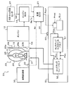
- FIG. 10 It is a schematic block diagram of the motor vehicle 10 which is a vehicle carrying the power transmission device 20 including the lockup device based on the Example of this invention.
- 2 is a schematic configuration diagram of a power transmission device 20.
- FIG. It is a flowchart which shows an example of the lockup slip control routine performed by transmission ECU21 of an Example. It is a flowchart which shows an example of the setting procedure of oil pressure command value Pslu *. It is explanatory drawing which shows an example of the map for prediction engine torque setting. It is explanatory drawing which shows an example of the map for correction value setting.
- 6 is a time chart illustrating how the engine speed Ne, the engine torque Te, the throttle opening THR, and the hydraulic pressure command value Pslu * change when the throttle opening THR rapidly increases during the slip control.
- 7 is a time chart illustrating how the engine speed Ne, the engine torque Te, the throttle opening THR, and the hydraulic pressure command value Pslu * change when the throttle opening THR rapidly decreases during the slip control.
- FIG. 1 is a schematic configuration diagram of an automobile 10 that is a vehicle equipped with a power transmission device 20 including a lock-up device according to an embodiment of the present invention
- FIG. 2 is a schematic configuration diagram of the power transmission device 20.
- An automobile 10 shown in FIG. 1 includes an engine 12 that is an internal combustion engine that outputs power by explosion combustion of a mixture of hydrocarbon fuel such as gasoline and light oil and air, and an electronic control unit for engine that controls the operation of the engine 12. (Hereinafter referred to as “engine ECU”) 14, a brake electronic control unit (hereinafter referred to as “brake ECU”) 15 for controlling an electronically controlled hydraulic brake unit (not shown), a fluid transmission device (starting device) 23, and the like.
- working fluid working fluid
- shift ECU shift electronic control unit
- the engine ECU 14 has an accelerator depression amount Acc from an accelerator pedal position sensor 92 that detects a depression amount (operation amount) of an accelerator pedal 91, a vehicle speed V from a vehicle speed sensor 99, The throttle opening THR from the throttle opening sensor 97 that detects the opening of the electronically controlled throttle valve 13 that changes according to the accelerator depression amount Acc, the crankshaft position sensor (not shown) that detects the rotation of the crankshaft 16, etc. Signals from various sensors and the like, signals from the brake ECU 15 and the shift ECU 21 and the like are input, and the engine ECU 14 controls a throttle valve 13, a fuel injection valve, a spark plug, etc. (not shown) based on these signals.
- the engine ECU 14 calculates the rotational speed Ne of the engine 12 based on a signal from the crankshaft position sensor and, for example, the rotational speed Ne of the engine 12 or an intake air amount of the engine 12 detected by an air flow meter (not shown) or Based on the throttle opening THR, a predetermined map or calculation formula, engine torque Te, which is an estimated value of torque output from the engine 12, is derived (calculated).
- the brake ECU 15 receives the master cylinder pressure detected by the master cylinder pressure sensor 94 when the brake pedal 93 is depressed, the vehicle speed V from the vehicle speed sensor 99, signals from various sensors (not shown), the engine ECU 14 and the transmission ECU 21.
- the brake ECU 15 controls a brake actuator (hydraulic actuator) (not shown) and the like based on these signals.
- the shift ECU 21 of the power transmission device 20 includes a shift range sensor 96 that detects an operation position of the shift lever 95 for selecting a desired shift range from a plurality of shift ranges.
- the oil temperature OT from the temperature sensor 55 for detecting the temperature of the hydraulic oil supplied to the engine, the throttle opening THR from the throttle opening sensor 97, signals from various sensors (not shown), signals from the engine ECU 14 and the brake ECU 15 , Etc.
- the engine ECU 14, the brake ECU 15 and the speed change ECU 21 are all configured as a microcomputer centered on a CPU (not shown). In addition to the CPU, a ROM for storing a processing program, a RAM for temporarily storing data, an RAM for storing data. An output port and a communication port (both not shown) are provided.
- the engine ECU 14, the brake ECU 15 and the transmission ECU 21 are connected to each other via a bus line or the like, and exchange of data necessary for control is executed between these ECUs as needed.
- the power transmission device 20 includes a fluid transmission device 23 housed in a transmission case 22, a hydraulic unit 50 that supplies hydraulic pressure to the fluid transmission device 23 and the automatic transmission 30, and an oil pump (not shown) connected to the hydraulic unit 50. And automatic transmission 30 and the like.
- the fluid transmission device 23 is configured as a fluid torque converter with a lock-up clutch, and as shown in FIG. 2, the input side is connected to the crankshaft 16 of the engine 12 via a front cover 18 as an input member.
- the pump impeller 24 as a fluid transmission element, and the turbine runner 25, the pump impeller 24 and the turbine runner 25 as an output side fluid transmission element fixed to an input shaft (input member) 31 of the automatic transmission 30 via a turbine hub.
- a stator 26 that is arranged inside and rectifies the flow of hydraulic oil from the turbine runner 25 to the pump impeller 24, a one-way clutch 27 that restricts the rotational direction of the stator 26 in one direction, and a lock-up clutch 28 connected to the turbine runner 25.
- the fluid transmission device 23 functions as a torque amplifier due to the action of the stator 26 when the rotational speed difference between the pump impeller 24 and the turbine runner 25 is large, and functions as a fluid coupling when the rotational speed difference between the two is small.
- the lock-up clutch 28 can execute lock-up for connecting the pump impeller 24, that is, the front cover 18 as an input member, and the turbine runner 25 (turbine hub), that is, the input shaft 31 of the automatic transmission 30, and release of the lock-up. It is a thing. When a predetermined lock-up on condition is satisfied after the vehicle 10 is started, the pump impeller 24 and the turbine runner 25 are locked (directly connected) by the lock-up clutch 28, and the power from the engine 12 is mechanically connected to the input shaft 31. And it will be transmitted directly.
- the hydraulic unit 50 adjusts the hydraulic oil from the oil pump to generate the line pressure PL, or reduces the line pressure PL to reduce the secondary pressure Psec.
- the secondary regulator valve to be generated, the modulator valve to adjust the line pressure PL to generate a constant modulator pressure Pmod, and the hydraulic oil can be supplied to a plurality of clutches and brakes of the automatic transmission 30 according to the operation position of the shift lever 95.
- Manual valves, and a plurality of linear solenoid valves that can regulate hydraulic oil (line pressure PL) from the manual valves and output them to the corresponding clutches and brakes (all not shown). Further, as shown in FIG.
- the hydraulic unit 50 operates the lock-up clutch 28 of the fluid transmission device 23, and the current value applied from the auxiliary battery according to the hydraulic command value Pslu * set by the transmission ECU 21 as shown in FIG.
- a lockup solenoid valve SLU that generates a lockup solenoid pressure Pslu by adjusting the modulator pressure Pmod from the modulator valve in response to the secondary pressure from the secondary regulator valve in response to the lockup solenoid pressure Pslu from the lockup solenoid valve SLU.
- the lockup control valve 51 that regulates the pressure Psec to generate the lockup clutch pressure Pluc to the lockup clutch 28 and the lockup solenoid pressure Pslu from the lockup solenoid valve SLU are transmitted.
- a lock-up relay valve 52 to allow, restrict the supply of the lock-up clutch pressure Pluc from the lock-up control valve 51 as a pressure to the lock-up chamber 23b of the hydraulic transmission 23.
- the lockup solenoid valve SLU sets the lockup solenoid pressure Pslu to a value of 0 when the hydraulic pressure command value Pslu * (applied current value) is relatively small (the lockup solenoid pressure Pslu is not generated).
- the lockup solenoid pressure Pslu is set higher as the hydraulic pressure command value Pslu * increases.
- the lockup control valve 51 reduces the secondary pressure Psec, which is the original pressure, as the lockup solenoid pressure Pslu increases, thereby reducing the lockup clutch pressure Pluc.
- the lockup clutch pressure Pluc required for complete engagement of the lockup clutch 28 is output when the lockup solenoid pressure Pslu is equal to or higher than a predetermined lockup engagement pressure P1.
- the lockup relay valve 52 supplies the secondary pressure Psec from the secondary regulator valve to the lockup chamber 23b of the fluid transmission device 23 when the lockup solenoid pressure Pslu is not supplied from the lockup solenoid valve SLU, and the lockup solenoid valve 52 locks up.
- the lockup solenoid pressure Pslu is supplied from the solenoid valve SLU
- the secondary pressure Psec from the secondary regulator valve is supplied to the fluid transmission chamber 23a and the lockup clutch pressure Pluc from the lockup control valve 51 is supplied to the lockup chamber 23b. It is configured to supply.
- the lockup solenoid pressure Pslu generated by the lockup solenoid valve SLU is supplied to the lockup control valve 51 and the lockup relay valve 52
- the lockup clutch pressure Pluc (secondary) generated by the lockup control valve 51 is provided. Pressure lower than the pressure Psec) is supplied from the lockup relay valve 52 to the lockup chamber 23b, and the secondary pressure Psec from the secondary regulator valve is supplied from the lockup relay valve 52 to the fluid transmission chamber 23a.
- the lockup piston 28p moves to the engagement side as the pressure in the lockup chamber 23b decreases, and the lockup clutch 28 is fully engaged when the lockup solenoid pressure Pslu reaches the lockup engagement pressure P1 or higher. The lockup is completed.
- slip control is executed to gradually decrease the hydraulic pressure supplied to the lock-up chamber 23b so that the torque capacity of the lock-up clutch 28 gradually increases.
- production of the vibration resulting from the torque fluctuation accompanying lockup can be suppressed.
- slip control so as to cause the lockup clutch 28 to slip during acceleration or deceleration of the automobile 10, power transmission efficiency and fuel consumption of the engine 12 can be improved.
- FIG. 3 is a flowchart showing an example of a lock-up slip control routine that is repeatedly executed by the transmission ECU 21 at predetermined time intervals (for example, 10 msec) when the slip control execution condition is satisfied.
- the transmission ECU 21 At the start of the lockup slip control routine, the transmission ECU 21 according to the embodiment first starts the throttle opening THR and the shift range SR of the throttle valve 13, the input shaft rotational speed Nin of the automatic transmission 30, and the hydraulic oil in the hydraulic unit 50. Necessary for execution of slip control such as the temperature OT, the rotational speed Ne of the engine 12, the engine torque Te that is an estimated value of the torque output from the engine 12, and the values of the flags Ftipin and Ftipout that are set to the initial value 0 Data is input (step S100).
- the rotational speed Ne of the engine 12 and the engine torque Te are input from the engine ECU 14 by communication.
- step S100 If the necessary data is input in step S100, the input shaft speed Nin of the automatic transmission 30 is subtracted from the input speed Ne of the engine 12, whereby the front cover 18 as the input member and the automatic transmission 30 A slip rotation speed Nslip indicating a rotation speed difference from the input shaft 31 is calculated (step S110). Subsequently, a target slip rotational speed (target slip speed) Nslip * corresponding to the state of the vehicle 10 is set based on the shift range SR input in step 100, the input shaft rotational speed Nin of the automatic transmission 30, and the engine torque Te. (Step S120).
- the relationship between the shift range SR, the input shaft rotational speed Nin of the automatic transmission 30 and the engine torque Te and the target slip rotational speed Nslip * is determined in advance, and the shift ECU 21 is not shown as a target slip rotational speed setting map.
- the target slip rotation speed Nslip * corresponding to the given shift range SR, the input shaft rotation speed Nin of the automatic transmission 30, and the engine torque Te is derived and set from the map. .
- the target slip speed Nslip * is set in this way, the value obtained by subtracting the throttle opening THR input at the previous execution of this routine from the throttle opening THR input at step S100 is divided by the execution cycle dt of this routine.
- a throttle opening change amount dTHR which is a change amount per unit time of the throttle opening THR, is calculated (step S130).
- step S140 it is determined whether or not both of the flags Ftipin and Ftipout input in step S100 are 0 (step S140). If both of the flags Ftipin and Ftipout are 0, the flags Ftipin and It is determined whether any one of Ftipout is inverted from the value 1 to the value 0 (step S150). When the flag Ftipin or Ftipout is inverted from the value 1 to the value 0, it is further determined whether or not a predetermined time has elapsed since the latest inversion of the flag Ftipin or Ftipout (step S160). If it is determined in step S150 that both the flags Ftipin and Ftipout are not inverted from the value 1 to the value 0, the process of step S160 is skipped.
- step S150 If it is determined in step S150 that both the flags Ftipin and Ftipout are not inverted from the value 1 to the value 0, and it is determined in step S160 that a predetermined time has elapsed since the latest inversion of the flag Ftipin or Ftipout. If so, it is determined whether or not the throttle opening change amount dTHR calculated in step S130 is larger than the increase-side threshold value ⁇ in (positive value) (step S170).
- the increase side threshold value ⁇ in impairs the responsiveness and accuracy of the derivation (calculation) of the engine torque Te by the engine ECU 14 and influences the control delay of the hydraulic pressure setting by the hydraulic unit 50 and the communication delay between the engine ECU 14 and the transmission ECU 21
- the amount of increase in the throttle opening THR during execution of slip control that may increase the engine speed is determined in advance by experiments and analysis.
- step S170 it may be determined whether or not the state in which the throttle opening change amount dTHR is larger than the increase-side threshold value ⁇ in has continued for a predetermined time or more.
- step S170 If it is determined in step S170 that the throttle opening change amount dTHR is larger than the increase-side threshold value ⁇ in, the target slip rotation speed Nslip * set in step S120 and the slip rotation speed calculated in step S110 are further determined. It is determined whether or not the difference from Nslip (Nslip * ⁇ Nslip) is equal to or less than a predetermined value ⁇ in (for example, a negative value) (step S180).
- a predetermined value ⁇ in for example, a negative value
- step S180 If the torque capacity of the lock-up clutch 28 is insufficient with respect to the increase in the torque actually output from the engine 12, the slip rotation speed Nslip increases due to the increase in the rotation speed Ne of the engine 12, and the target slip rotation speed Nslip *. And the slip rotation speed Nslip (Nslip * ⁇ Nslip) increases toward the negative side. Therefore, if it is determined in step S180 that the difference between the target slip rotation speed Nslip * and the slip rotation speed Nslip (Nslip * ⁇ Nslip) is equal to or less than the predetermined value ⁇ in, the target value is increased due to a rapid increase in the throttle opening THR. Considering that there is a possibility that the continuation of the slip control at the slip rotation speed Nslip * may be hindered, the flag Ftipin is set to the value 1 and the flag Ftipout is maintained at the value 0 (step S190). *
- step S170 when it is determined in step S170 that the throttle opening change amount dTHR is equal to or smaller than the increase side threshold value ⁇ in, the throttle opening change amount dTHR calculated in step S130 is smaller than the decrease side threshold value ⁇ out (negative value). It is determined whether it is small (step S200). Decrease-side threshold value ⁇ out impairs responsiveness and accuracy of derivation of engine torque Te by engine ECU 14 and increases the influence on control of delay in response of hydraulic pressure setting by hydraulic unit 50 and communication delay between engine ECU 14 and transmission ECU 21. The amount of decrease in the throttle opening THR during the execution of the slip control that is likely to occur is determined in advance by experiments and analysis. In step S200, it may be determined whether or not the state in which the throttle opening change amount dTHR is smaller than the decrease-side threshold value ⁇ out continues for a predetermined time or more.
- step S200 When it is determined in step S200 that the throttle opening change amount dTHR is smaller than the decrease-side threshold value ⁇ out, the target slip rotation speed Nslip * set in step S120 and the slip rotation speed calculated in step S110 are further determined. It is determined whether or not the difference from Nslip (Nslip * ⁇ Nslip) is greater than or equal to a predetermined value ⁇ out (positive value) (step S210).
- a predetermined value ⁇ out positive value
- step S210 when the torque capacity of the lockup clutch 28 becomes excessive with respect to the decrease in the torque actually output from the engine 12, the slip rotation speed Nslip becomes smaller due to the decrease in the rotation speed Ne of the engine 12, and the target slip rotation speed Nslip.
- the difference between * and the slip rotation speed Nslip (Nslip * ⁇ Nslip) increases to the positive side.
- the target slip rotation speed Nslip * and the slip rotation speed Nslip (Nslip * ⁇ Nslip) is equal to or greater than the predetermined value ⁇ out, the target value is reduced due to a rapid decrease in the throttle opening THR.
- the flag Ftipin is maintained at the value 0 and the flag Ftipout is set to the value 1 (step S220).
- step S180 when it is determined in step S180 that the difference (Nslip * ⁇ Nslip) between the target slip rotation speed Nslip * and the slip rotation speed Nslip is larger than the predetermined value ⁇ in, the throttle opening change is changed in step S200.
- the amount dTHR is equal to or greater than the decrease-side threshold value ⁇ out (the throttle opening change amount dTHR is within the range from the decrease-side threshold value ⁇ out to the increase-side threshold value ⁇ in, and the throttle opening amount THR does not increase or decrease rapidly.
- step S210 When the difference between the target slip rotational speed Nslip * and the slip rotational speed Nslip (Nslip * ⁇ Nslip) is less than the predetermined value ⁇ out in step S210, the slip control can be continued satisfactorily. Assuming both the flag Ftipin and the flag Ftipout are maintained at the value 0. (Step S230). If either flag Ftipin or Ftipout is set to a value of 1 in step S190 or S220, a negative determination is made in step S140 during the next execution of this routine.
- step S130 Whether or not the state where the absolute value of the calculated throttle opening change amount dTHR is equal to or less than a predetermined relatively small value ⁇ continues for a predetermined time or more, that is, whether or not the change in the throttle opening THR is stable. Is determined (step S240). Then, when an affirmative determination is made in step S240, both the flag Ftipin and the flag Ftipout are maintained at the value 0 (step S230). Further, if it is determined in step S160 that the predetermined time has not elapsed since the last inversion of the flag Ftipin or Ftipout, both the flag Ftipin and the flag Ftipout are maintained at the value 0 in order to suppress control hunting. (Step S230).
- step S250 the lockup solenoid valve SLU is controlled based on the hydraulic pressure command value Pslu * (step S260), and the processing after step S100 is executed again.
- step S250 The procedure for setting the hydraulic pressure command value Pslu * in step S250 will be described with reference to FIG.
- the shift ECU 21 determines whether both the flags Ftipin and Ftipout are 0 (step S2500), and both the flags Ftipin and Ftipout are set to values. If 0, the hydraulic pressure command feedforward term Psluff is set based on the engine torque Te input in step S100, the input shaft rotational speed Nin of the automatic transmission 30, and the target slip rotational speed Nslip * set in step S120. Setting is performed (step S2510).
- the relationship between the engine torque Te, the input shaft rotational speed Nin, the target slip rotational speed Nslip *, and the hydraulic pressure command feedforward term Psluff is determined in advance, and the unillustrated ROM of the transmission ECU 21 is used as a feedforward term setting map (not shown).
- the hydraulic command feedforward term Psluff corresponding to the applied engine torque Te, input shaft rotational speed Nin, and target slip rotational speed Nslip * is derived and set from the map.
- the hydraulic pressure command value Pslu * is set so as to cancel the difference between the target slip rotation speed Nslip * and the slip rotation speed Nslip according to a predetermined calculation formula.
- the hydraulic pressure command feedback term Pslufb is calculated (step S2530).
- the sum of the hydraulic pressure command feedforward term Psluff, the correction value dPslu, and the hydraulic pressure command feedback term Pslub is set as the hydraulic pressure command value Pslu * (step S2540).
- step S2500 if it is determined in step S2500 that one of the flags Ftipin and Ftipout is a value 1, the predicted engine torque Test is set based on the throttle opening THR input in step S100 (step S2550). ). That is, when the flag Ftipin or Ftipout is 1, the responsiveness and accuracy of the engine ECU 14 derivation of the engine torque Te are impaired by the sudden increase or decrease of the throttle opening change amount dTHR as described above, or the hydraulic unit 50 The engine torque Te input from the engine ECU 14 in step S100 is actually output from the engine 12 because the influence on the control of the response delay of the hydraulic pressure setting and the control of the communication delay between the engine ECU 14 and the transmission ECU 21 increases. There is a risk of deviation from the torque.
- step S100 input is made in step S100 to set the hydraulic pressure command value Pslu * so as to be more suitable for the torque actually output from the engine 12.
- a predicted engine torque Test that is a second estimated value of the torque actually output from the engine 12 is set.
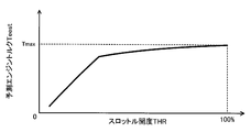
- the relationship between the throttle opening degree THR and the predicted engine torque Test is determined in advance and stored in a ROM (not shown) of the speed change ECU 21 as a predicted engine torque setting map (predicted drive source torque setting constraint), step S2550. Then, the predicted engine torque Test corresponding to the throttle opening THR input in step S100 is derived and set from the map.
- FIG. 5 shows an example of a predicted engine torque setting map. The predicted engine torque setting map of the embodiment is determined through experiments and analysis so as to define the torque that is estimated to be actually output from the engine 12 for each throttle opening.
- the predicted engine torque Tee derived in step S2550 from the predicted engine torque setting map is changed so that the engine torque Te input in step S100, that is, the throttle opening change amount dTHR exceeds the increase side threshold value ⁇ in.
- the engine torque Te transmitted from the engine ECU 14 to the speed change ECU 21 increases, and the throttle opening change amount dTHR changes beyond the decrease-side threshold value ⁇ out.
- the predicted engine torque Test corresponding to each throttle opening THR does not increase the torque capacity of the lockup clutch 28 when the throttle opening increases, and the throttle opening.
- the torque capacity of the lockup clutch 28 is adapted not to be insufficient.
- the maximum value Tmax of the predicted engine torque Test in the predicted engine torque setting map for increasing the throttle opening is, for example, about 40-80% of the rated torque of the engine 12. It should be noted that when the throttle opening THR is increased, the predicted engine torque Test is increased so that the torque capacity of the lock-up clutch 28 does not become excessive (so that the lock-up clutch 28 is not suddenly engaged).
- the maximum value Tmax is suppressed to make it look small (for example, about 40% of the rated torque), and when the throttle opening THR is decreased, the predicted engine torque Tee is made too small so that the torque capacity of the lockup clutch 28 is not insufficient (locked).
- step S2560 a hydraulic pressure command feedforward term Psluff corresponding to the predicted engine torque Teest, the input shaft rotational speed Nin, and the target slip rotational speed Nslip * given from the above-described feedforward term setting map is derived and set.
- a reference time tref1 set based on the oil temperature OT of the hydraulic oil (step) S2570).
- the reference time tref1 is derived from a map (not shown) in which the relationship between the oil temperature OT and the reference time tref1 is determined in advance.
- the reference time tref1 is longer as the hydraulic oil temperature OT is lower, that is, the hydraulic oil viscosity is higher. Is set as follows. *
- step S2570 If it is determined in step S2570 that the elapsed time t is less than or equal to the reference time tref1, the hydraulic pressure command value Pslu * is determined based on the values of the flags Ftipin and Ftipout and the engine torque Te input in step S100.
- a correction value dPslu is set (step S2580).
- the flag Ftipin is a value 1 and the throttle opening THR is increasing
- the flag Ftipout is a value 1 and the throttle opening THR is decreasing
- the relationship between the engine torque Te and the correction value dPslu is determined in advance and stored in a ROM (not shown) of the transmission ECU 21 as a correction value setting map.
- the correction value dPslu corresponding to the engine torque Te input in step S100 is derived and set from the correction value setting map for increasing the throttle opening.
- the correction value dPslu corresponding to the engine torque Te input in step S100 is derived and set from the correction value setting map for reducing the throttle opening.
- the correction value setting map for increasing the throttle opening shows a correction value dPslu in a stepwise manner so as to promote an increase in the torque capacity of the lockup clutch 28 as the engine torque Te increases. It is determined through experiments and analysis so as to be largely defined. Further, as shown in FIG.
- the correction value setting map for reducing the throttle opening defines the correction value dPslu to be reduced stepwise so as to promote the decrease in the torque capacity of the lockup clutch 28 as the engine torque Te increases. It is determined through experiments and analysis.
- the correction value setting map includes a case where the flag Ftipin is 1 and the throttle opening THR is increasing, and a case where the flag Ftipout is 1 and the throttle opening THR is decreasing. May be determined so as to define the relationship between the predicted engine torque Test and the correction value dPslu.
- step S2530 the hydraulic pressure command feedback term Pslub of the hydraulic pressure command value Pslu * is calculated so as to cancel the difference between the target slip rotational speed Nslip * and the slip rotational speed Nslip according to the above formula (step S2530). )
- the sum of the hydraulic command feedforward term Psluff, the correction value dPslu, and the hydraulic command feedback term Pslub is set as the hydraulic command value Pslu * (step S2540). If it is determined in step S2570 that the elapsed time t has exceeded the reference time tref1, the correction value dPslu is set to 0 in step S2520, and the processes in steps S2530 and S2540 are executed.
- FIG. 7 schematically shows an example of how the engine speed Ne, the engine torque Te, the throttle opening THR, and the hydraulic pressure command value Pslu * change when the throttle opening THR suddenly increases during the slip control.
- FIG. 8 shows changes in the rotational speed Ne, the engine torque Te, the throttle opening THR, and the hydraulic pressure command value Pslu * when the throttle opening THR rapidly decreases during the slip control. It is a time chart which shows an example of a mode to do typically.
- the solid line indicates the behavior of each value when the above-described lock-up slip control routine is executed, and the broken line in the figure indicates the engine torque Te derived by the engine ECU 14,
- the alternate long and two short dashes lines indicate the engine speed Ne and the hydraulic pressure command value Pslu * when the processes in steps S2550 to S2580 of FIG. 4 are not executed.
- step S190 in FIG. Ftipin is set to the value 1
- the predicted engine torque Test is set in step S2550 of FIG.
- the elapsed time t after the hydraulic pressure command feedforward term Psluff is set based on the predicted engine torque Test and the flag Ftipin is set to the value 1 exceeds the reference time tref1 (time t0 to time t1).
- the correction value dPslu is set to a positive value corresponding to the engine torque Te, and the hydraulic pressure command value Pslu * corresponding to the correction value dPslu * is the hydraulic pressure command value Pslu * when the processing of steps S2550 to S2580 in FIG. 7 (see the alternate long and short dash line). Further, when the elapsed time t exceeds the reference time tref1 at time t1 in FIG. 7, the correction value dPslu is set to the value 0 (step S2520 in FIG. 4), so that the hydraulic pressure command value Pslu * is reduced from the previous value.
- the hydraulic pressure command value Pslu * is the hydraulic pressure command value Pslu when the processing of steps S2550 to S2580 in FIG. 4 is not executed. Set to a value that is basically higher than *.
- the response and accuracy of the derivation of the engine torque Te by the engine ECU 14 are impaired due to the rapid increase in the throttle opening THR during the execution of the slip control, or the response of the hydraulic pressure setting by the hydraulic unit 50
- the hydraulic pressure command feedforward term Psluff is set based on the predicted engine torque Test corresponding to the throttle opening THR, thereby
- the hydraulic pressure command value Pslu * for the unit 50 can be set so as to be more suitable for the torque actually output from the engine 12.
- the hydraulic pressure command feedforward term Psluff is set based on the predicted engine torque Test corresponding to the throttle opening THR, so that the hydraulic pressure for the hydraulic unit 50 is set.
- the command value Pslu * can be set so as to be more suitable for the torque actually output from the engine 12.
- the engine torque Te is estimated to be large by setting the torque capacity of the lock-up clutch 28 appropriately.
- the slip control can be satisfactorily continued without causing a decrease in the rotational speed Ne of 12 (see the two-dot chain line in the figure).
- the slip rotational speed Nslip which is the rotational speed difference between the front cover 18 and the input shaft 31 of the automatic transmission 30 due to the half-engagement of the lockup clutch 28, depends on the state of the vehicle 10.
- the throttle opening change amount dTHR is within a predetermined range from the decrease-side threshold value ⁇ out to the increase-side threshold value ⁇ in.
- the hydraulic pressure command value Pslu to the hydraulic unit 50 so that the slip rotational speed Nslip becomes the target slip rotational speed Nslip * and corresponds to the engine torque Te that is an estimated value of the output torque of the engine 12 derived by the engine ECU 14.
- step S2510-S2 in FIG. 4 Is set (steps S2510-S2 in FIG. 4). 540). Further, when the slip control is executed, if the throttle opening change amount dTHR becomes larger than the increase side threshold value ⁇ in which is the upper limit of the above range due to the increase in the throttle opening THR, the release condition in step S240 in FIG. A predicted engine torque Test, which is an estimated value of the output torque of the engine 12 according to the throttle opening THR, is derived until it is established, so that the slip rotational speed Nslip becomes the target slip rotational speed Nslip * and corresponds to the predicted engine torque Test. Is set to the hydraulic pressure command value Pslu * (steps S2550-S2580, S2530, S2540 in FIG. 4).
- the throttle opening degree change amount dTHR becomes larger than the increase side threshold value ⁇ in due to the increase in the throttle opening degree THR during the slip control, the responsiveness and accuracy of the derivation of the engine torque Te by the engine ECU 14 are impaired. Therefore, the engine torque Te may be estimated to be small. If the hydraulic pressure command value Pslu * is set so as to correspond to the engine torque Te in such a case, the torque capacity of the lockup clutch 28 is insufficient, and the engine 12 is blown up during the slip control. There is a fear. On the other hand, when the throttle opening change amount dTHR becomes larger than the increase side threshold value ⁇ in during the execution of the slip control as in the above embodiment, it can be acquired with higher responsiveness instead of the engine torque Te.
- the hydraulic pressure command value Pslu * for the hydraulic unit 50 is set so as to correspond to the predicted engine torque Test
- the hydraulic pressure command value Pslu * is actually obtained from the engine 12. It can be adapted to the output torque. As a result, even if the throttle opening THR is increased during the slip control, the slip control can be satisfactorily continued without causing the engine 12 to blow up due to the small estimation of the engine torque Te. Become.
- the correction value dPslu is set only for the reference time tref corresponding to the oil temperature OT in the hydraulic unit 50 after the throttle opening change amount dTHR becomes larger than the increase-side threshold value ⁇ in due to the increase in the throttle opening THR. Then, the hydraulic pressure command value Pslu * is corrected so that an increase in the torque capacity of the lockup clutch 28 is promoted (step S2540 in FIG. 4).
- the hydraulic pressure command value Pslu is transmitted from the hydraulic unit 50 to the lockup clutch 28.
- the hydraulic pressure corresponding to * can be supplied with good responsiveness so that the torque capacity of the lock-up clutch 28 can be adapted to the torque actually output from the engine 12.
- the throttle opening THR is set to the throttle opening THR until the release condition in step S240 in FIG. 3 is satisfied.
- the corresponding predicted engine torque Test is derived, the slip rotational speed Nslip becomes the target slip rotational speed Nslip *, and the hydraulic pressure command value Pslu * is set so as to correspond to the predicted engine torque Test (steps S2550 to S2580 in FIG. 4). , S2530, S2540).
- the hydraulic pressure command value Pslu * is adapted to the torque actually output from the engine 12 Can be a thing. As a result, even if the throttle opening THR is reduced during the slip control, the slip control can be satisfactorily continued.
- the correction value dPslu is set for the time corresponding to the oil temperature OT in the hydraulic unit 50 after the throttle opening change amount dTHR becomes smaller than the decrease-side threshold value ⁇ out due to the decrease in the throttle opening THR (Ste S2580 in FIG. 4), and thereby the hydraulic pressure command value Pslu * is corrected so as to promote a decrease in the torque capacity of the lockup clutch 28 (step S2540 in FIG. 4).
- the hydraulic pressure command value Pslu is transmitted from the hydraulic unit 50 to the lockup clutch 28.
- the hydraulic pressure corresponding to * can be supplied with good responsiveness so that the torque capacity of the lock-up clutch 28 can be adapted to the torque actually output from the engine 12.
- the engine ECU 14 for deriving the engine torque Te and the shift ECU 21 for executing the slip control are separate from each other, and the throttle opening change amount dTHR is increased by the increase of the throttle opening THR during the slip control.
- the influence on the control of the communication delay between the engine ECU 14 and the speed change ECU 21 increases when the increase side threshold value ⁇ in becomes larger.
- the predicted drive source according to the throttle opening THR If the hydraulic pressure command value Pslu * is set so as to correspond to the predicted drive source torque Test while deriving the torque Test, it is possible to eliminate the influence on the communication delay control between the engine ECU 14 and the transmission ECU 21.
- the accelerator operation amount and the change amount of the accelerator operation amount substantially corresponding to the throttle opening THR and the throttle opening change amount dTHR are set. It may be used.
- the lockup clutch 28 is included in the fluid transmission device 23, the present invention may be applied to a single clutch that is not combined with a fluid coupling or the like.
- the front cover 18 as an input member connected to the engine 12 that is the drive source of the automobile 10 and the input shaft 31 of the automatic transmission 30 can be connected and the connection between the two can be released.
- the lock-up clutch 28 corresponds to a “lock-up clutch”
- the hydraulic unit 50 that supplies hydraulic pressure to the lock-up clutch 28 corresponds to a “hydraulic unit”
- the engine ECU 14 for deriving the engine torque Te corresponds to “drive source torque acquisition means”
- the speed change ECU 21 that executes the lock-up slip control routine of FIG. 3 is used as “slip control means” or “accelerator opening change amount acquisition means”.
- the shift E for executing the processing of steps S2500 to S2580 of FIG. U21 corresponds to the "hydraulic pressure command value setting means”.
- the present invention can be used in the lockup device manufacturing industry.
Abstract
Description
車両の駆動源に接続された入力部材と変速装置の入力軸とを連結すると共に両者の連結を解除することができるロックアップクラッチと、該ロックアップクラッチに油圧を供給する油圧ユニットと、前記ロックアップクラッチの半係合により前記入力部材と前記変速装置の入力軸との回転速度差が前記車両の状態に応じた目標スリップ速度になるように前記油圧ユニットを制御するスリップ制御手段とを備えるロックアップ装置において、
前記スリップ制御手段は、
前記駆動源を制御すると共に前記スリップ制御手段とは別体である駆動源制御手段から該駆動源の出力トルクの推定値である駆動源トルクを取得する駆動源トルク取得手段と、 アクセル開度の変化量であるアクセル開度変化量を取得するアクセル開度変化量取得手段と、
前記アクセル開度変化量が予め定められた範囲内にある場合には、前記回転速度差が前記目標スリップ速度になるように前記駆動源トルクに対応した前記油圧ユニットへの油圧指令値を設定し、前記アクセル開度の増加により前記アクセル開度変化量が前記範囲の上限よりも大きくなった場合には、前記アクセル開度に応じた前記駆動源の出力トルクの推定値である予測駆動源トルクを導出して前記回転速度差が前記目標スリップ速度になるように該予測駆動源トルクに対応した前記油圧指令値を設定する油圧指令値設定手段とを含むことを特徴とする。 The lock-up device of the present invention is
A lockup clutch capable of connecting an input member connected to a drive source of a vehicle and an input shaft of a transmission and releasing the connection between the input member, a hydraulic unit supplying hydraulic pressure to the lockup clutch, and the lock A lock comprising slip control means for controlling the hydraulic unit so that a difference in rotational speed between the input member and the input shaft of the transmission becomes a target slip speed according to the state of the vehicle by half-engagement of an up clutch. Up device,
The slip control means includes
Drive source torque acquisition means for controlling the drive source and acquiring drive source torque that is an estimated value of output torque of the drive source from a drive source control means that is separate from the slip control means; An accelerator opening change amount acquisition means for acquiring an accelerator opening change amount which is a change amount;
When the accelerator opening change amount is within a predetermined range, a hydraulic pressure command value to the hydraulic unit corresponding to the drive source torque is set so that the rotational speed difference becomes the target slip speed. When the accelerator opening change amount becomes larger than the upper limit of the range due to an increase in the accelerator opening, a predicted drive source torque that is an estimated value of the output torque of the drive source according to the accelerator opening And a hydraulic pressure command value setting means for setting the hydraulic pressure command value corresponding to the predicted drive source torque so that the rotational speed difference becomes the target slip speed.
ロックアップクラッチの半係合により車両の駆動源に接続された入力部材と変速装置の入力軸との回転速度差が該車両の状態に応じた目標スリップ速度になるように該ロックアップクラッチに油圧を供給する油圧ユニットを制御するロックアップの制御方法であって、
(a)前記駆動源を制御する駆動源制御手段から該駆動源の出力トルクの推定値である駆動源トルクを取得すると共にアクセル開度の変化量であるアクセル開度変化量を取得するステップと、
(b)前記アクセル開度変化量が予め定められた範囲内にある場合には、前記入力部材と前記変速装置の入力軸との回転速度差が前記車両の状態に応じた目標スリップ速度になるように前記駆動源トルクに対応した前記油圧ユニットへの油圧指令値を設定し、前記アクセル開度の増加により前記アクセル開度変化量が前記範囲の上限よりも大きくなった場合には、前記アクセル開度に応じた前記駆動源の出力トルクの推定値である予測駆動源トルクを導出して前記回転速度差が前記目標スリップ速度になるように該予測駆動源トルクに対応した前記油圧指令値を設定するステップと、
(c)前記油圧指令値に応じた油圧を前記ロックアップクラッチに供給するように前記油圧ユニットを制御するステップと、
を含むものである。 The control method of the lockup device of the present invention includes:
The lockup clutch is hydraulically controlled so that the difference in rotational speed between the input member connected to the drive source of the vehicle and the input shaft of the transmission becomes a target slip speed according to the state of the vehicle by half-engagement of the lockup clutch. A lock-up control method for controlling a hydraulic unit for supplying
(A) obtaining a drive source torque that is an estimated value of an output torque of the drive source from a drive source control means that controls the drive source, and obtaining an accelerator opening change amount that is a change amount of the accelerator opening; ,
(B) When the amount of change in the accelerator opening is within a predetermined range, the rotational speed difference between the input member and the input shaft of the transmission becomes a target slip speed corresponding to the state of the vehicle. If the hydraulic pressure command value to the hydraulic unit corresponding to the drive source torque is set, and the accelerator opening change amount becomes larger than the upper limit of the range due to the increase of the accelerator opening, the accelerator A predicted drive source torque that is an estimated value of the output torque of the drive source according to the opening is derived, and the hydraulic pressure command value corresponding to the predicted drive source torque is set so that the rotational speed difference becomes the target slip speed. Steps to set,
(C) controlling the hydraulic unit to supply a hydraulic pressure corresponding to the hydraulic pressure command value to the lockup clutch;
Is included.
れる電流値)がある程度大きくなると、それ以後、油圧指令値Pslu*が大きいほどロックアップソレノイド圧Psluを高く設定する。また、ロックアップコントロールバルブ51は、ロックアップソレノイドバルブSLUによりロックアップソレノイド圧Psluが生成されるときにロックアップソレノイド圧Psluが高いほど元圧であるセカンダリ圧Psecを減圧してロックアップクラッチ圧Plucを低く設定し、ロックアップソレノイド圧Psluが予め定められたロックアップ係合圧P1以上であるときにロックアップクラッチ28の完全係合に要求されるロックアップクラッチ圧Plucを出力する。更に、ロックアップリレーバルブ52は、ロックアップソレノイドバルブSLUからロックアップソレノイド圧Psluが供給されないときに流体伝動装置23のロックアップ室23bにセカンダリレギュレータバルブからのセカンダリ圧Psecを供給し、かつロックアップソレノイドバルブSLUからロックアップソレノイド圧Psluが供給されるときに流体伝動室23aにセカンダリレギュレータバルブからのセカンダリ圧Psecを供給すると共にロックアップ室23bにロックアップコントロールバルブ51からのロックアップクラッチ圧Plucを供給するように構成されている。 In the embodiment, the lockup solenoid valve SLU sets the lockup solenoid pressure Pslu to a value of 0 when the hydraulic pressure command value Pslu * (applied current value) is relatively small (the lockup solenoid pressure Pslu is not generated). When the hydraulic pressure command value Pslu * (applied current value) increases to some extent, the lockup solenoid pressure Pslu is set higher as the hydraulic pressure command value Pslu * increases. In addition, when the lockup solenoid pressure Pslu is generated by the lockup solenoid valve SLU, the lockup control valve 51 reduces the secondary pressure Psec, which is the original pressure, as the lockup solenoid pressure Pslu increases, thereby reducing the lockup clutch pressure Pluc. Is set low, and the lockup clutch pressure Pluc required for complete engagement of the
Claims (5)
- 車両の駆動源に接続された入力部材と変速装置の入力軸とを連結すると共に両者の連結を解除することができるロックアップクラッチと、該ロックアップクラッチに油圧を供給する油圧ユニットと、前記ロックアップクラッチの半係合により前記入力部材と前記変速装置の入力軸との回転速度差が前記車両の状態に応じた目標スリップ速度になるように前記油圧ユニットを制御するスリップ制御手段とを備えるロックアップ装置において、
前記スリップ制御手段は、
前記駆動源を制御すると共に前記スリップ制御手段とは別体である駆動源制御手段から該駆動源の出力トルクの推定値である駆動源トルクを取得する駆動源トルク取得手段と、 単位時間あたりのアクセル開度の変化量であるアクセル開度変化量を取得するアクセル開度変化量取得手段と、
前記アクセル開度変化量が予め定められた範囲内にある場合には、前記回転速度差が前記目標スリップ速度になるように前記駆動源トルクに対応した前記油圧ユニットへの油圧指令値を設定し、前記アクセル開度の増加により前記アクセル開度変化量が前記範囲の上限よりも大きくなった場合には、前記アクセル開度に応じた前記駆動源の出力トルクの推定値である予測駆動源トルクを導出して前記回転速度差が前記目標スリップ速度になるように該予測駆動源トルクに対応した前記油圧指令値を設定する油圧指令値設定手段とを含むことを特徴とするロックアップ装置。 A lockup clutch capable of connecting an input member connected to a drive source of a vehicle and an input shaft of a transmission and releasing the connection between the input member, a hydraulic unit supplying hydraulic pressure to the lockup clutch, and the lock A lock comprising slip control means for controlling the hydraulic unit so that a difference in rotational speed between the input member and the input shaft of the transmission becomes a target slip speed according to the state of the vehicle by half-engagement of an up clutch. Up device,
The slip control means includes
A drive source torque acquisition unit that controls the drive source and acquires a drive source torque that is an estimated value of the output torque of the drive source from a drive source control unit that is separate from the slip control unit; An accelerator opening change amount acquisition means for acquiring an accelerator opening change amount which is a change amount of the accelerator opening;
When the accelerator opening change amount is within a predetermined range, a hydraulic pressure command value to the hydraulic unit corresponding to the drive source torque is set so that the rotational speed difference becomes the target slip speed. When the accelerator opening change amount becomes larger than the upper limit of the range due to an increase in the accelerator opening, a predicted drive source torque that is an estimated value of the output torque of the drive source according to the accelerator opening And a hydraulic pressure command value setting means for setting the hydraulic pressure command value corresponding to the predicted driving source torque so that the rotational speed difference becomes the target slip speed. - 請求項1に記載のロックアップ装置において、
前記アクセル開度変化量が予め定められた範囲内にある場合、前記油圧指令値は、前記駆動源トルクに対応した油圧指令フィードフォワード項を含み、前記アクセル開度の増加により前記アクセル開度変化量が前記範囲の上限よりも大きくなった場合、前記油圧指令値は、前記予測駆動源トルクに対応した油圧指令フィードフォワード項を含み、前記アクセル開度の増加により前記アクセル開度変化量が前記範囲の上限よりも大きくなってから所定時間だけ前記油圧指令値には前記ロックアップクラッチのトルク容量の増加を促進させるための補正値が加算されることを特徴とするロックアップ装置。 The lockup device according to claim 1,
When the accelerator opening change amount is within a predetermined range, the oil pressure command value includes a hydraulic command feedforward term corresponding to the drive source torque, and the accelerator opening change is increased by increasing the accelerator opening. When the amount becomes larger than the upper limit of the range, the hydraulic pressure command value includes a hydraulic pressure command feedforward term corresponding to the predicted drive source torque, and the accelerator opening change amount is increased by increasing the accelerator opening. A lockup device, wherein a correction value for accelerating an increase in torque capacity of the lockup clutch is added to the hydraulic pressure command value for a predetermined time after becoming larger than the upper limit of the range. - 請求項1または2に記載のロックアップ装置において、
前記油圧指令値設定手段は、前記アクセル開度の減少により前記アクセル開度変化量が前記範囲の下限よりも小さくなった場合に、前記アクセル開度に応じた予測駆動源トルクを導出して前記回転速度差が前記目標スリップ速度になるように該予測駆動源トルクに対応した前記油圧指令値を設定することを特徴とするロックアップ装置。 The lockup device according to claim 1 or 2,
The hydraulic pressure command value setting means derives a predicted drive source torque according to the accelerator opening when the accelerator opening change amount is smaller than a lower limit of the range due to a decrease in the accelerator opening. The lockup device characterized in that the hydraulic pressure command value corresponding to the predicted driving source torque is set so that a rotational speed difference becomes the target slip speed. - 請求項3に記載のロックアップ装置において、
前記アクセル開度の減少により前記アクセル開度変化量が前記範囲の下限よりも小さくなってから所定時間だけ前記油圧指令値から前記ロックアップクラッチのトルク容量の減少を促進させるための補正値が減算されることを特徴とするロックアップ装置。 The lockup device according to claim 3, wherein
A correction value for promoting a decrease in the torque capacity of the lockup clutch is subtracted from the hydraulic pressure command value for a predetermined time after the accelerator opening change amount becomes smaller than the lower limit of the range due to the decrease in the accelerator opening. A lockup device. - ロックアップクラッチの半係合により車両の駆動源に接続された入力部材と変速装置の入力軸との回転速度差が該車両の状態に応じた目標スリップ速度になるように該ロックアップクラッチに油圧を供給する油圧ユニットを制御するロックアップの制御方法であって、
(a)前記駆動源を制御する駆動源制御手段から該駆動源の出力トルクの推定値である駆動源トルクを取得すると共にアクセル開度の変化量であるアクセル開度変化量を取得するステップと、
(b)前記アクセル開度変化量が予め定められた範囲内にある場合には、前記入力部材と前記変速装置の入力軸との回転速度差が前記車両の状態に応じた目標スリップ速度になるように前記駆動源トルクに対応した前記油圧ユニットへの油圧指令値を設定し、前記アクセル開度の増加により前記アクセル開度変化量が前記範囲の上限よりも大きくなった場合には、前記アクセル開度に応じた前記駆動源の出力トルクの推定値である予測駆動源トルクを導出して前記回転速度差が前記目標スリップ速度になるように該予測駆動源トルクに対応した前記油圧指令値を設定するステップと、
(c)前記油圧指令値に応じた油圧を前記ロックアップクラッチに供給するように前記油圧ユニットを制御するステップと、
を含むロックアップ装置の制御方法。 The lockup clutch is hydraulically controlled so that the difference in rotational speed between the input member connected to the drive source of the vehicle and the input shaft of the transmission becomes a target slip speed according to the state of the vehicle by half-engagement of the lockup clutch. A lock-up control method for controlling a hydraulic unit for supplying
(A) obtaining a drive source torque that is an estimated value of an output torque of the drive source from a drive source control means that controls the drive source, and obtaining an accelerator opening change amount that is a change amount of the accelerator opening; ,
(B) When the amount of change in the accelerator opening is within a predetermined range, the rotational speed difference between the input member and the input shaft of the transmission becomes a target slip speed corresponding to the state of the vehicle. If the hydraulic pressure command value to the hydraulic unit corresponding to the drive source torque is set, and the accelerator opening change amount becomes larger than the upper limit of the range due to the increase of the accelerator opening, the accelerator A predicted drive source torque that is an estimated value of the output torque of the drive source according to the opening is derived, and the hydraulic pressure command value corresponding to the predicted drive source torque is set so that the rotational speed difference becomes the target slip speed. Steps to set,
(C) controlling the hydraulic unit to supply a hydraulic pressure corresponding to the hydraulic pressure command value to the lockup clutch;
A method for controlling a lockup device including:
Priority Applications (2)
| Application Number | Priority Date | Filing Date | Title |
|---|---|---|---|
| DE112011102613T DE112011102613T5 (en) | 2010-12-02 | 2011-11-25 | Lock-up device and control method for lock-up device |
| CN201180045174.4A CN103119338B (en) | 2010-12-02 | 2011-11-25 | Lock-up device and control method for lock-up device |
Applications Claiming Priority (2)
| Application Number | Priority Date | Filing Date | Title |
|---|---|---|---|
| JP2010-269620 | 2010-12-02 | ||
| JP2010269620A JP5464134B2 (en) | 2010-12-02 | 2010-12-02 | Lock-up device and control method thereof |
Publications (1)
| Publication Number | Publication Date |
|---|---|
| WO2012073834A1 true WO2012073834A1 (en) | 2012-06-07 |
Family
ID=46162991
Family Applications (1)
| Application Number | Title | Priority Date | Filing Date |
|---|---|---|---|
| PCT/JP2011/077244 WO2012073834A1 (en) | 2010-12-02 | 2011-11-25 | Lock-up apparatus and method for controlling same |
Country Status (5)
| Country | Link |
|---|---|
| US (1) | US8886435B2 (en) |
| JP (1) | JP5464134B2 (en) |
| CN (1) | CN103119338B (en) |
| DE (1) | DE112011102613T5 (en) |
| WO (1) | WO2012073834A1 (en) |
Cited By (1)
| Publication number | Priority date | Publication date | Assignee | Title |
|---|---|---|---|---|
| JP2020169696A (en) * | 2019-04-03 | 2020-10-15 | トヨタ自動車株式会社 | Vehicular control apparatus |
Families Citing this family (14)
| Publication number | Priority date | Publication date | Assignee | Title |
|---|---|---|---|---|
| JP6015503B2 (en) * | 2012-10-31 | 2016-10-26 | アイシン・エィ・ダブリュ株式会社 | Start clutch control device and control method |
| JP6196857B2 (en) * | 2013-09-13 | 2017-09-13 | ジヤトコ株式会社 | Vehicle control device |
| CN106795961B (en) * | 2014-09-03 | 2018-04-06 | 日产自动车株式会社 | The lock-up clutch control apparatus of vehicle |
| JP6123811B2 (en) * | 2015-01-19 | 2017-05-10 | トヨタ自動車株式会社 | Slip control device for lock-up clutch |
| JP6358137B2 (en) * | 2015-03-17 | 2018-07-18 | トヨタ自動車株式会社 | Slip control device for lock-up clutch |
| CN107407408B (en) * | 2015-03-30 | 2019-11-01 | 加特可株式会社 | The control device and control method of automatic transmission |
| KR101992072B1 (en) * | 2015-08-24 | 2019-06-21 | 쟈트코 가부시키가이샤 | Lock-up clutch control device and lock-up clutch control method for vehicle |
| JP6288043B2 (en) * | 2015-11-11 | 2018-03-07 | トヨタ自動車株式会社 | Control device for lock-up clutch |
| JP6428690B2 (en) * | 2016-03-23 | 2018-11-28 | トヨタ自動車株式会社 | Control device for vehicle power transmission device |
| JP2022001765A (en) * | 2018-08-02 | 2022-01-06 | ジヤトコ株式会社 | Slip control device of torque converter |
| US10746291B2 (en) * | 2019-01-17 | 2020-08-18 | Ford Global Technologies, Llc | Engine torque and torque converter bypass clutch slip control during vehicle launch |
| CN111645686B (en) * | 2020-06-05 | 2021-10-22 | 中国第一汽车股份有限公司 | Driving force recovery control method and device and 48V driving system |
| CN112303224B (en) * | 2020-10-30 | 2022-05-17 | 重庆长安汽车股份有限公司 | Method and system for controlling lock-up clutch of automatic transmission with hydraulic torque converter |
| CN114607507B (en) * | 2022-03-11 | 2023-06-02 | 中国第一汽车股份有限公司 | Engine rotating speed detection method and device, computer equipment and medium |
Citations (4)
| Publication number | Priority date | Publication date | Assignee | Title |
|---|---|---|---|---|
| JP2008008321A (en) * | 2006-06-27 | 2008-01-17 | Nissan Motor Co Ltd | Lock-up control device for torque converter |
| JP2009150494A (en) * | 2007-12-21 | 2009-07-09 | Jatco Ltd | Lock-up clutch control device of automatic change gear |
| JP2010133488A (en) * | 2008-12-04 | 2010-06-17 | Nissan Motor Co Ltd | Device and method of controlling slip of torque converter |
| JP2010210008A (en) * | 2009-03-10 | 2010-09-24 | Nissan Motor Co Ltd | Control device for lock-up clutch of vehicle |
Family Cites Families (11)
| Publication number | Priority date | Publication date | Assignee | Title |
|---|---|---|---|---|
| US5105926A (en) | 1988-12-28 | 1992-04-21 | Mazda Motor Corporation | Slip control system for torque converter of automatic transmission |
| JP2818888B2 (en) * | 1988-12-28 | 1998-10-30 | マツダ株式会社 | Fluid coupling slip control device |
| JPH03189469A (en) | 1989-07-20 | 1991-08-19 | Mazda Motor Corp | Slip control device for fluid coupling |
| US5626536A (en) * | 1994-07-19 | 1997-05-06 | Toyota Jidosha Kabushiki Kaisha | Lock-up clutch slip control apparatus and engine fuel-cut control apparatus for motor vehicle |
| JP3933091B2 (en) * | 2003-05-16 | 2007-06-20 | トヨタ自動車株式会社 | Hydraulic control circuit for fluid transmission device with lockup clutch for vehicle |
| JP4082700B2 (en) | 2004-07-16 | 2008-04-30 | 日産自動車株式会社 | Slip control device for torque converter |
| JP4133989B2 (en) | 2004-10-01 | 2008-08-13 | ジヤトコ株式会社 | Control device for continuously variable transmission |
| JP4598005B2 (en) * | 2007-01-25 | 2010-12-15 | 本田技研工業株式会社 | Control device for automatic transmission for vehicle |
| JP5266843B2 (en) * | 2008-03-31 | 2013-08-21 | アイシン・エィ・ダブリュ株式会社 | Control device for clutch |
| JP5225197B2 (en) | 2009-05-19 | 2013-07-03 | 三菱電機株式会社 | Vehicle position detection device |
| JP5331734B2 (en) * | 2010-03-09 | 2013-10-30 | ジヤトコ株式会社 | Control device for transmission mechanism and control method thereof |
-
2010
- 2010-12-02 JP JP2010269620A patent/JP5464134B2/en active Active
-
2011
- 2011-10-20 US US13/277,600 patent/US8886435B2/en active Active
- 2011-11-25 CN CN201180045174.4A patent/CN103119338B/en active Active
- 2011-11-25 DE DE112011102613T patent/DE112011102613T5/en not_active Withdrawn
- 2011-11-25 WO PCT/JP2011/077244 patent/WO2012073834A1/en active Application Filing
Patent Citations (4)
| Publication number | Priority date | Publication date | Assignee | Title |
|---|---|---|---|---|
| JP2008008321A (en) * | 2006-06-27 | 2008-01-17 | Nissan Motor Co Ltd | Lock-up control device for torque converter |
| JP2009150494A (en) * | 2007-12-21 | 2009-07-09 | Jatco Ltd | Lock-up clutch control device of automatic change gear |
| JP2010133488A (en) * | 2008-12-04 | 2010-06-17 | Nissan Motor Co Ltd | Device and method of controlling slip of torque converter |
| JP2010210008A (en) * | 2009-03-10 | 2010-09-24 | Nissan Motor Co Ltd | Control device for lock-up clutch of vehicle |
Cited By (2)
| Publication number | Priority date | Publication date | Assignee | Title |
|---|---|---|---|---|
| JP2020169696A (en) * | 2019-04-03 | 2020-10-15 | トヨタ自動車株式会社 | Vehicular control apparatus |
| JP7095646B2 (en) | 2019-04-03 | 2022-07-05 | トヨタ自動車株式会社 | Vehicle control unit |
Also Published As
| Publication number | Publication date |
|---|---|
| US8886435B2 (en) | 2014-11-11 |
| DE112011102613T5 (en) | 2013-05-08 |
| CN103119338B (en) | 2015-05-27 |
| JP2012117636A (en) | 2012-06-21 |
| CN103119338A (en) | 2013-05-22 |
| US20120143453A1 (en) | 2012-06-07 |
| JP5464134B2 (en) | 2014-04-09 |
Similar Documents
| Publication | Publication Date | Title |
|---|---|---|
| JP5464134B2 (en) | Lock-up device and control method thereof | |
| JP5776785B2 (en) | Control device and control method for lock-up clutch | |
| US9845870B2 (en) | Lock-up clutch control device and control method | |
| JP5377445B2 (en) | Vehicle control device | |
| JP6015503B2 (en) | Start clutch control device and control method | |
| JP5660180B2 (en) | Vehicle control device | |
| JP5789839B2 (en) | Control device for lock-up clutch | |
| JP5387784B2 (en) | Vehicle control device | |
| JP5994663B2 (en) | Vehicle control device | |
| JP5231948B2 (en) | Engine control apparatus and control method | |
| JP5625753B2 (en) | Vehicle control device | |
| JP6711085B2 (en) | Automatic transmission control device | |
| JP5533556B2 (en) | Vehicle control device | |
| JP2005140076A (en) | Vehicle control device relating to supply/stop control of fuel to engine as vehicle driving source, particularly, to stop control of fuel supply during idling for improved fuel economy | |
| JP5880458B2 (en) | Control device for continuously variable transmission | |
| JP2005140076A5 (en) | ||
| JP2008025376A (en) | Control device and control method for power train, program executing the control method, and recording medium recording the program | |
| JP2017032074A (en) | Controller of belt type continuously variable transmission | |
| US10161514B2 (en) | Control apparatus for lockup clutch | |
| JP2010242705A (en) | Control device and control method of vehicle | |
| JP5709303B2 (en) | Vehicle control device | |
| JP5157832B2 (en) | Vehicle control device | |
| WO2010097919A1 (en) | Automatic transmission control device | |
| WO2014112604A1 (en) | Lock-up-clutch control device and control method | |
| JP2009197983A (en) | Transmission unit, vehicle, and control method of transmission |
Legal Events
| Date | Code | Title | Description |
|---|---|---|---|
| WWE | Wipo information: entry into national phase |
Ref document number: 201180045174.4 Country of ref document: CN |
|
| 121 | Ep: the epo has been informed by wipo that ep was designated in this application |
Ref document number: 11845599 Country of ref document: EP Kind code of ref document: A1 |
|
| WWE | Wipo information: entry into national phase |
Ref document number: 112011102613 Country of ref document: DE Ref document number: 1120111026137 Country of ref document: DE |
|
| 122 | Ep: pct application non-entry in european phase |
Ref document number: 11845599 Country of ref document: EP Kind code of ref document: A1 |