WO2012070561A1 - Roll-press device - Google Patents
Roll-press device Download PDFInfo
- Publication number
- WO2012070561A1 WO2012070561A1 PCT/JP2011/076885 JP2011076885W WO2012070561A1 WO 2012070561 A1 WO2012070561 A1 WO 2012070561A1 JP 2011076885 W JP2011076885 W JP 2011076885W WO 2012070561 A1 WO2012070561 A1 WO 2012070561A1
- Authority
- WO
- WIPO (PCT)
- Prior art keywords
- roll
- press apparatus
- sheet
- crown shape
- region
- Prior art date
Links
- 238000000465 moulding Methods 0.000 claims description 31
- 239000011248 coating agent Substances 0.000 description 50
- 238000000576 coating method Methods 0.000 description 50
- 239000007772 electrode material Substances 0.000 description 11
- 238000013000 roll bending Methods 0.000 description 9
- 238000005096 rolling process Methods 0.000 description 8
- 239000007788 liquid Substances 0.000 description 6
- 239000000463 material Substances 0.000 description 5
- 238000005452 bending Methods 0.000 description 4
- 238000012937 correction Methods 0.000 description 4
- 238000010586 diagram Methods 0.000 description 4
- 230000007246 mechanism Effects 0.000 description 3
- 238000000034 method Methods 0.000 description 3
- 230000007423 decrease Effects 0.000 description 2
- 238000007599 discharging Methods 0.000 description 2
- 238000004519 manufacturing process Methods 0.000 description 2
- 238000012986 modification Methods 0.000 description 2
- 230000004048 modification Effects 0.000 description 2
- 238000003825 pressing Methods 0.000 description 2
- 230000008569 process Effects 0.000 description 2
- 238000013459 approach Methods 0.000 description 1
- 239000011230 binding agent Substances 0.000 description 1
- 230000008859 change Effects 0.000 description 1
- 239000000470 constituent Substances 0.000 description 1
- 238000013461 design Methods 0.000 description 1
- 238000009826 distribution Methods 0.000 description 1
- 238000001035 drying Methods 0.000 description 1
- 230000000694 effects Effects 0.000 description 1
- 239000012530 fluid Substances 0.000 description 1
- 238000005259 measurement Methods 0.000 description 1
- 238000012545 processing Methods 0.000 description 1
- 230000009467 reduction Effects 0.000 description 1
- 239000007787 solid Substances 0.000 description 1
- 238000011144 upstream manufacturing Methods 0.000 description 1
Images


Classifications
-
- B—PERFORMING OPERATIONS; TRANSPORTING
- B30—PRESSES
- B30B—PRESSES IN GENERAL
- B30B3/00—Presses characterised by the use of rotary pressing members, e.g. rollers, rings, discs
- B30B3/005—Roll constructions
-
- B—PERFORMING OPERATIONS; TRANSPORTING
- B30—PRESSES
- B30B—PRESSES IN GENERAL
- B30B3/00—Presses characterised by the use of rotary pressing members, e.g. rollers, rings, discs
- B30B3/04—Presses characterised by the use of rotary pressing members, e.g. rollers, rings, discs co-operating with one another, e.g. with co-operating cones
-
- B—PERFORMING OPERATIONS; TRANSPORTING
- B21—MECHANICAL METAL-WORKING WITHOUT ESSENTIALLY REMOVING MATERIAL; PUNCHING METAL
- B21B—ROLLING OF METAL
- B21B27/00—Rolls, roll alloys or roll fabrication; Lubricating, cooling or heating rolls while in use
- B21B27/02—Shape or construction of rolls
-
- H—ELECTRICITY
- H01—ELECTRIC ELEMENTS
- H01M—PROCESSES OR MEANS, e.g. BATTERIES, FOR THE DIRECT CONVERSION OF CHEMICAL ENERGY INTO ELECTRICAL ENERGY
- H01M4/00—Electrodes
- H01M4/02—Electrodes composed of, or comprising, active material
- H01M4/04—Processes of manufacture in general
-
- H—ELECTRICITY
- H01—ELECTRIC ELEMENTS
- H01M—PROCESSES OR MEANS, e.g. BATTERIES, FOR THE DIRECT CONVERSION OF CHEMICAL ENERGY INTO ELECTRICAL ENERGY
- H01M4/00—Electrodes
- H01M4/02—Electrodes composed of, or comprising, active material
- H01M4/04—Processes of manufacture in general
- H01M4/043—Processes of manufacture in general involving compressing or compaction
- H01M4/0435—Rolling or calendering
-
- B—PERFORMING OPERATIONS; TRANSPORTING
- B21—MECHANICAL METAL-WORKING WITHOUT ESSENTIALLY REMOVING MATERIAL; PUNCHING METAL
- B21B—ROLLING OF METAL
- B21B2269/00—Roll bending or shifting
- B21B2269/12—Axial shifting the rolls
- B21B2269/14—Work rolls
-
- B—PERFORMING OPERATIONS; TRANSPORTING
- B21—MECHANICAL METAL-WORKING WITHOUT ESSENTIALLY REMOVING MATERIAL; PUNCHING METAL
- B21B—ROLLING OF METAL
- B21B27/00—Rolls, roll alloys or roll fabrication; Lubricating, cooling or heating rolls while in use
- B21B27/02—Shape or construction of rolls
- B21B27/021—Rolls for sheets or strips
-
- Y—GENERAL TAGGING OF NEW TECHNOLOGICAL DEVELOPMENTS; GENERAL TAGGING OF CROSS-SECTIONAL TECHNOLOGIES SPANNING OVER SEVERAL SECTIONS OF THE IPC; TECHNICAL SUBJECTS COVERED BY FORMER USPC CROSS-REFERENCE ART COLLECTIONS [XRACs] AND DIGESTS
- Y02—TECHNOLOGIES OR APPLICATIONS FOR MITIGATION OR ADAPTATION AGAINST CLIMATE CHANGE
- Y02E—REDUCTION OF GREENHOUSE GAS [GHG] EMISSIONS, RELATED TO ENERGY GENERATION, TRANSMISSION OR DISTRIBUTION
- Y02E60/00—Enabling technologies; Technologies with a potential or indirect contribution to GHG emissions mitigation
- Y02E60/10—Energy storage using batteries
Definitions
- the present invention relates to a roll press apparatus.
- This application claims priority based on Japanese Patent Application No. 2010-261486 for which it applied to Japan on November 24, 2010, and uses the content here.
- a rolling device for rolling a plate material for example, as shown in Patent Document 1, an apparatus for rolling a plate material between a pair of opposed rolls is used.
- a method is used in which a correction mechanism that corrects bending of a roll during rolling is installed to make the thickness of a sheet material uniform.
- rolls having regions having different inclination angles in a crown shape are arranged to face each other, and the opposed rolls are moved in a direction opposite to the rotation axis direction, thereby forming a sheet. The thickness at the end and the thickness at the center of the sheet are adjusted.
- Non-Patent Document 1 in the process of manufacturing a secondary battery, an electrode material sheet in which an electrode material is disposed on an electrode plate base plate as a base material can be manufactured by a roll press apparatus. Proposed.
- a roll press apparatus is for compressing and molding an electrode material disposed on an electrode plate base plate, and is different from the above-described rolling apparatus for rolling an object and thinly deforming it.
- attempts have been made to uniformize the thickness of the electrode material sheet using a correction mechanism that corrects the deflection of the roll.
- an electrode material sheet is manufactured by a roll press apparatus
- a plurality of coating films containing electrode materials are arranged in multiple rows in the width direction of the electrode plate base plate.
- a plurality of coating films arranged in a strip are pressed between rolls at a time.
- the coating film applied as a different strip is formed by discharging the coating liquid from different nozzles, there may be variations in the thickness of the coating film for each strip due to variations in nozzle ejection accuracy. That is, in the roll press apparatus, the thickness of the molding target (for example, coating liquid) tends to vary.
- the present invention has been made in view of the above-described problems, and in a roll press apparatus, even when the thickness of a molding target on a sheet varies, the molding target can be molded to a desired thickness. For the purpose.
- a roll press that presses the molding object arranged on the sheet in the gap between the first roll and the second roll arranged opposite to each other together with the sheet. It is an apparatus, Comprising: The crown shape of the said 1st roll and the said 2nd roll has an inclination area
- the first roll and the second roll can be moved in the opposite directions along the rotation axis direction by the roll moving device. For this reason, if the crown shape of the first roll and the second roll is not a straight line, the gap distance in the rotation axis direction can be changed depending on the location by moving the first roll and the second roll in opposite directions. it can.
- the molding target can be molded to a desired thickness.
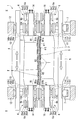
- FIG. 2 is a schematic diagram showing a cross section taken along line II-II in FIG. 1. It is a schematic diagram for demonstrating operation
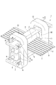
- the roll press apparatus 1 of this embodiment manufactures an electrode material sheet by pressing and molding a plurality of coating films T (molding targets) arranged in multiple lines on the electrode plate S, together with the sheet.
- the upper roll 2 first roll
- the lower roll 3 second roll
- the upper shift beam 4 first shift beam
- the lower shift beam 5 A second shift beam
- a roll bending device 6 a gap adjusting device 7
- an upper roll shift cylinder 8 first cylinder
- second roll shift cylinder 9 second cylinder.
- the coating film T is a material including an electrode material, and is a solid obtained by drying a predetermined amount of a binder of a fluid (coating liquid) including the electrode material. For this reason, even if it is a case where the coating film T is apply
- the upper roll 2 abuts on the upper side of the electrode plate mother plate S to mold the coating film T on the electrode plate mother plate S, and the rotation axis is in a horizontal direction perpendicular to the traveling direction of the electrode plate mother plate S. It is arranged toward.
- the upper roll 2 is disposed above the lower roll 3, and is disposed to face the lower roll 3 in parallel.
- the lower roll 3 abuts on the lower side of the electrode plate base plate S to form the coating film T on the electrode plate base plate S, and is disposed below the upper roll 2 in parallel with the upper roll 2. Has been.
- Each of the upper roll 2 and the lower roll 3 is connected to a drive device (not shown), and the rotational power is transmitted from the drive device toward the traveling direction of the electrode plate base plate S. They are driven to rotate at the same speed in opposite directions.
- the crown shape of the upper roll 2 (the contour shape of the pressing surface when viewed from the traveling direction of the electrode plate S) is an end region. It is comprised by R1 and center area
- the end region R1a is a region that presses the end of the electrode plate base plate S, and is provided on the left end side in the rotation axis direction of the upper roll 2 in FIG.
- the end region R1b is a region that presses the end of the electrode plate base plate S, and is provided on the right end side in the rotation axis direction of the upper roll 2 in FIG.
- regions R1a and R1b are inclined by inclination-angle (theta) 1 with respect to the rotating shaft of the upper side roll 2 in the gap. Specifically, the end region R1a is reduced in diameter toward the left side in FIG. The end region R1b increases in diameter toward the right side in FIG.
- press working is performed on an electrode plate base plate S in which eight coating films T are arranged at equal intervals in the width direction. I do. That is, in the electrode plate base plate S that is pressed by the roll press device 1 of the present embodiment, a plurality of coating films T are arranged in multiple rows in the width direction of the electrode plate base plate S. Such a coating film T is formed by supplying the coating liquid from one supply pipe and discharging the coating liquid from a nozzle arranged for each strip.
- the end region R1a has a width so as to press only the coating film T positioned at the leftmost end of the electrode plate base plate S among the plurality of coating films T arranged. Is set. Further, the end region R1b is set to have a width so as to press only the coating film T positioned at the rightmost end of the electrode plate mother plate S among the plurality of coating films T arranged.
- the central region R2 is a region that presses the central portion sandwiched between the end portions of the electrode plate mother plate S that is pressed by the end region R1a and R1b, and is sandwiched between the end region R1a and the end region R1b. Has been placed.
- the central region R2 is set at a different inclination angle from the end regions R1a and R1b. Specifically, the central region R2 is inclined in the negative direction when the inclination direction of the end regions R1a and R1b is a positive direction, and the inclination angle ⁇ 2 is larger than the inclination angle ⁇ 1 of the end regions R1a and R1b. It is set small. That is, the central region R2 is reduced in diameter toward the right side in FIG.
- the crown shape of the lower roll 3 is set to a shape that is inverted vertically and horizontally with respect to the crown shape of the upper roll 2. That is, the crown shape of the upper roll 2 and the crown shape of the lower roll 3 are the same. However, the end region R1a of the upper roll 2 is located at the left end in FIG. 2, but the end region R1a of the lower roll 3 is located at the right end in FIG. Further, the end region R1b of the upper roll 2 is located at the right end in FIG. 2, but the end region R1b of the lower roll 3 is located at the left end in FIG. That is, the lower roll 3 is reversed with respect to the upper roll 2. As a result, since the lower roll 3 is arranged in parallel with the upper roll 2, the crown shape of the lower roll 3 is the end region R1a as in the crown shape of the upper roll 2, as shown in FIG. , R1b and the central region R2.
- the upper roll 2 is moved in a direction to move the end regions R1a away from each other and bring the end regions R1b closer to each other.
- the lower roll 3 are moved in opposite directions along the rotation axis direction (in FIG. 2, when the upper roll 2 is moved to the left side and the lower roll 3 is moved to the right side), The central regions R2 are far from each other (see FIG. 3A).
- the gap distance in the region where the outermost coating film T of the multi-layered coating films T is molded is reduced, and the gap distance in the other regions is increased (see the same figure).
- the upper roll 2 and the lower roll 3 are The rate of change of the gap distance when moving in the opposite direction is larger in the region where the outermost one of the coating films T arranged in the strip is molded than in the other regions.
- the upper shift beam 4 is disposed above the upper roll 2, and a bearing 10 that pivotally supports the upper roll 2 is fixed and disposed along the upper roll 2.
- the lower shift beam 5 is disposed below the lower roll 3, and a bearing 11 that pivotally supports the lower roll 3 is fixed and disposed along the lower roll 3.
- a pair of frames 12 arranged to face each other are fixed to both end sides of the upper roll 2 and the lower roll 3.
- the bearing 10 and the bearing 11 are supported by the frame 12, thereby supporting the upper roll 2, the lower roll 3, the upper shift beam 4, and the lower shift beam 5.
- the bearing 10 and the bearing 11 are supported so that it can slide independently in the rotating shaft direction of the upper roll 2 and the lower roll 3.
- the bearing 10 is fixed to the upper shift beam 4 via the axle box 10A, and the inner race 10a is fixed to the upper roll 2, and the outer race is fixed to the axle box 10A. 10b, and a roller 10c interposed between the inner race 10a and the outer race 10b.
- the bearing 11 is fixed to the lower shift beam 5 via the axle box 11A, and is fixed to the inner race 11a fixed to the lower roll 3 and the axle box 11A.
- the outer race 11b includes a roller 11c interposed between the inner race 11a and the outer race 11b.
- the roll bending device 6 is for correcting the bending of the upper roll 2 or the lower roll 3. As shown in FIG. 2, the roll bending apparatus 6 is provided for each of the upper roll 2 and the lower roll 3.
- the roll bending device 6 that corrects the deflection of the upper roll 2 is fixed to the upper shift beam 4 and is connected to both ends of the upper roll 2 by bearings 6a. Then, the roll bending device 6 corrects the bending by curving the upper roll 2 by lifting or lowering both ends of the upper roll 2 supported by the bearing 10. As shown in FIG. 2, the bearing 6a is fixed to the upper shift beam 4 via a shaft box 6b, and an inner race 6a1 fixed to the upper roll 2 and an outer race fixed to the shaft box 6b. 6a2 and a roller 6a3 interposed between the inner race 6a1 and the outer race 6a2.
- the roll bending device 6 that corrects the deflection of the lower roll 3 is fixed to the lower shift beam 5 and is connected to both ends of the upper roll 2 by bearings 6a.
- the roll bending device 6 corrects the bending by curving the lower roll 3 by lifting or lowering both ends of the lower roll 3 supported by the bearing 11.
- the bearing 6a is fixed to the lower shift beam 5 via a shaft box 6b, and is fixed to the inner race 6a1 fixed to the lower roll 3 and the shaft box 6b. It has an outer race 6a2 and a roller 6a3 interposed between the inner race 6a1 and the outer race 6a2.
- a positioning sleeve 13 is provided between the inner race 10a of the bearing 10 and the roll body of the upper roll 2, and between the inner race 10a of the bearing 10 and the inner race 6a1 of the bearing 6a. Is installed.
- a positioning cup 14 for positioning the inner race 6a1 of the bearing 6a is bolted to the end of the upper roll 2. The positioning sleeve 13 and the positioning cup 14 position the bearing 10, the bearing 6 a, and the upper roll 2.
- a positioning sleeve is provided between the inner race 11a of the bearing 11 and the roll body of the lower roll 3, and between the inner race 11a of the bearing 11 and the inner race 6a1 of the bearing 6a. 15 is installed.
- a positioning cup 16 for positioning the inner race 6a1 of the bearing 6a is bolted to the end of the lower roll 3. The positioning sleeve 15 and the positioning cup 16 position the bearing 11, the bearing 6 a, and the lower roll 2.
- the gap adjusting device 7 adjusts the gap distance between the upper roll 2 and the lower roll 3, and is installed on the frame 12.
- the gap adjusting device 7 adjusts the gap distance between the upper roll 2 and the lower roll 3 by moving the lower shift beam 5 up and down.
- the upper roll shift cylinder 8 moves the upper roll 2 in the rotation axis direction, is fixed to the frame 12, and is connected to the upper shift beam 4.
- the upper roll shift cylinder 8 moves the upper roll 2 in the rotation axis direction by pushing or pulling the upper shift beam 4 in the rotation axis direction of the upper roll 2.
- the lower roll shift cylinder 9 moves the lower roll 3 in the rotation axis direction, is fixed to the frame 12, and is connected to the lower shift beam 5.
- the lower roll shift cylinder 9 moves the lower roll 3 in the rotation axis direction by pushing or pulling the lower shift beam 5 in the rotation axis direction of the lower roll 3.
- the roll moving apparatus of this invention is comprised by the above-mentioned upper side roll shift cylinder 8 and the lower side roll shift cylinder 9.
- FIG. 1 the roll moving apparatus of this invention is comprised by the above-mentioned upper side roll shift cylinder 8 and the lower side roll shift cylinder 9.
- the roll press apparatus 1 of this embodiment is provided with a control device (not shown), and is controlled by the upper roll shift cylinder 8 and the lower roll shift cylinder 9 under the control of the control device.
- the roll 3 is moved parallel to the rotation axis and in the opposite direction.
- an electrode plate base plate S in which a plurality of coating films T are arranged in a gap between the upper roll 2 and the lower roll 3 is supplied.
- the coating film T is pressed together with the electrode plate base plate S only with a load applied by the upper roll 2 and the lower roll 3 in the gap.
- the deflection of the upper roll 2 and the lower roll 3 is corrected by the roll bending device 6. Further, the overall adjustment of the gap distance is performed by the gap adjusting device 7.
- a coating film T is discharged and applied to the electrode plate S from a plurality of nozzles arranged in the width direction of the electrode plate S.
- the coating film T is supplied from one pipe to all the nozzles, the nozzle located at the end of the plurality of nozzles has a lower internal pressure and the discharge amount is smaller than that of the other nozzles.
- decrease of the discharge amount of the coating film T is shown.
- the control device acquires the thickness information of the coating film T based on the measurement result of the thickness measuring device disposed downstream of the roll press device 1 and the command from the operation unit operated by the operator.
- the upper roll 2 and the lower roll 3 are set so that the gap distance in the end region R1 and the gap distance in the central region R2 are equal. And bring them closer together.
- the upper roll 2 and the lower roll 3 can be moved in opposite directions along the rotation axis direction. For this reason, if the crown shape of the upper roll 2 and the lower roll 3 is not a straight line as in this embodiment, the gap in the rotation axis direction can be obtained by moving the upper roll 2 and the lower roll 3 in opposite directions. The distance can be changed depending on the location. Therefore, according to the roll press apparatus 1 of the present embodiment, the coating film T can be molded to a desired thickness even when the thickness of the coating film T on the electrode plate base plate S varies. Is possible.
- the upper roll 2 and the lower roll 3 having the end region R1 and the central region R2 are arranged at the end portion of the electrode plate base plate S where the thickness variation is most likely to occur.
- the thickness of the applied coating film T can be changed flexibly.
- the upper roll 2 is moved by moving the upper shift beam 4, and the lower roll 3 is moved by moving the lower shift beam 5.
- An actuator that directly contacts the upper roll 2 and the lower roll 3 can also be used as a roll moving device.
- the upper roll 2 and the lower roll 3 are moved, There is a possibility that a load acts locally on a part of the lower roll 3 to cause an undesirable deformation in the upper roll 2 and the lower roll 3.
- the upper roll 2 is moved by moving the upper shift beam 4, and the lower roll 3 is moved by moving the lower shift beam 5, so that the upper roll 2 and the lower roll 3 are moved.
- the roll press apparatus 1 of the present embodiment presses the coating film T with a load applied by the upper roll 2 and the lower roll 3. For this reason, it is not necessary to provide the backup roll installed when the further load is required, and it is a simple and cheap roll press apparatus. Further, by adopting such a configuration, it is possible to easily install the upper shift beam 4 and the lower shift beam 5 as described above, and to adjust the gap distance with high accuracy.
- the present invention is not limited to this, and can be applied to a press roll apparatus that places a molding object other than the coating film T on a sheet other than the electrode plate base plate S and presses it. Further, the present invention can be applied to a roll press apparatus for forming a coating film formed by applying some coating liquid on a sheet, for example, a process for producing an electrode material sheet used for a solar cell Can also be used.
- the structure by which the coating film T was made into a series in the advancing direction of the electrode plate mother board S was demonstrated.
- the coating film for performing molding in the present invention is not limited to this, and the coating film may be divided into a plurality in the traveling direction of the electrode plate base plate S.
- the crown shape of the upper side roll 2 and the lower side roll 3 demonstrated the structure formed with the straight line.
- the present invention is not limited to this, and it is also possible to employ a configuration in which the end regions R1a, R1b and the central region R2 are curved as shown in FIG.
- the rolls 2 and 3 are rounded as described above, the effect that the fluctuation of the distribution of the roll gap in the plate width direction due to the deflection of the roll axis can be corrected and controlled by shifting the rolls 2 and 3 is increased.
- the molding target can be molded to a desired thickness.
Abstract
Description
本願は、2010年11月24日に日本国に出願された特願2010-261486号に基づき優先権を主張し、その内容をここに援用する。 The present invention relates to a roll press apparatus.
This application claims priority based on Japanese Patent Application No. 2010-261486 for which it applied to Japan on November 24, 2010, and uses the content here.
このような圧延装置では、例えば特許文献1に示すように、圧延時におけるロールの撓みを補正する補正機構を設置し、シート材の厚みを均一とする方法が用いられている。
また、圧延装置では、例えば特許文献2に示すように、クラウン形状において傾斜角度が異なる領域を有するロールを対向配置し、対向配置されたロールを回転軸方向の反対方向に移動することによって、シート端部における厚みとシート中央部における厚みとを調節している。 Conventionally, as a rolling device for rolling a plate material, for example, as shown in
In such a rolling apparatus, for example, as shown in
Further, in the rolling apparatus, for example, as shown in
このようなロールプレス装置は、極板母板上に配置された電極材を圧縮して成型するためのものであり、対象物を圧延して薄く変形させる上述の圧延装置とは異なるものであるが、非特許文献1に記載されているように、ロールの撓みを補正する補正機構を用いて電極材シートの厚みを均一化する試みがなされている。 By the way, in recent years, as shown in Non-Patent
Such a roll press apparatus is for compressing and molding an electrode material disposed on an electrode plate base plate, and is different from the above-described rolling apparatus for rolling an object and thinly deforming it. However, as described in
そして、異なる条として塗布される塗布膜は、異なるノズルから塗布液が吐出されて形成されるため、ノズルの吐出精度のばらつきから、条ごとの塗布膜の厚みにばらつきが生じることがある。
つまり、ロールプレス装置では、成型対象(例えば塗布液)の厚みにばらつきが生じやすい。 However, in general, when an electrode material sheet is manufactured by a roll press apparatus, in order to enable mass production, a plurality of coating films containing electrode materials are arranged in multiple rows in the width direction of the electrode plate base plate. A plurality of coating films arranged in a strip are pressed between rolls at a time.
And since the coating film applied as a different strip is formed by discharging the coating liquid from different nozzles, there may be variations in the thickness of the coating film for each strip due to variations in nozzle ejection accuracy.
That is, in the roll press apparatus, the thickness of the molding target (for example, coating liquid) tends to vary.
このため、第1ロールと第2ロールとのクラウン形状が直線でなければ、第1ロールと第2ロールとを反対方向に移動させることによって、回転軸方向におけるギャップ距離を場所によって変化させることができる。 According to the present invention, the first roll and the second roll can be moved in the opposite directions along the rotation axis direction by the roll moving device.
For this reason, if the crown shape of the first roll and the second roll is not a straight line, the gap distance in the rotation axis direction can be changed depending on the location by moving the first roll and the second roll in opposite directions. it can.
なお、塗布膜Tは、電極材材料を含む材料であり、電極材材料を含む流動体(塗布液)のバインダが所定量乾燥してやや固化したものである。このため、塗布膜Tは、極板母板Sの下側面に塗布された場合であっても、極板母板Sから剥離することなく固着する。 The
The coating film T is a material including an electrode material, and is a solid obtained by drying a predetermined amount of a binder of a fluid (coating liquid) including the electrode material. For this reason, even if it is a case where the coating film T is apply | coated to the lower surface of the electrode plate mother board S, it adheres, without peeling from the electrode plate mother board S.
この上側ロール2は、下側ロール3の上方に配置されており、前記下側ロール3と平行に対向配置されている。 The
The
そして、2つの端部領域R1a,R1bは、ギャップにおいて上側ロール2の回転軸に対して傾斜角度θ1にて傾斜されている。具体的には、端部領域R1aは、図2において左側に向かうにつれて縮径している。端部領域R1bは、図2において右側に向かうにつれて拡径している。 The end region R1a is a region that presses the end of the electrode plate base plate S, and is provided on the left end side in the rotation axis direction of the
And two edge part area | regions R1a and R1b are inclined by inclination-angle (theta) 1 with respect to the rotating shaft of the
このような塗布膜Tは、1つの供給管から塗布液が供給されると共に条ごとに配置されるノズルから塗布液が吐出されて形成される。 In the
Such a coating film T is formed by supplying the coating liquid from one supply pipe and discharging the coating liquid from a nozzle arranged for each strip.
この中央領域R2は、端部領域R1a,R1bと異なる傾斜角度に設定されている。具体的には、中央領域R2は、端部領域R1a,R1bの傾斜方向が正方向とすると、負方向に傾斜されており、その傾斜角度θ2が端部領域R1a,R1bの傾斜角度θ1よりも小さく設定されている。すなわち、中央領域R2は、図2において右側に向かうにつれて縮径している。 The central region R2 is a region that presses the central portion sandwiched between the end portions of the electrode plate mother plate S that is pressed by the end region R1a and R1b, and is sandwiched between the end region R1a and the end region R1b. Has been placed.
The central region R2 is set at a different inclination angle from the end regions R1a and R1b. Specifically, the central region R2 is inclined in the negative direction when the inclination direction of the end regions R1a and R1b is a positive direction, and the inclination angle θ2 is larger than the inclination angle θ1 of the end regions R1a and R1b. It is set small. That is, the central region R2 is reduced in diameter toward the right side in FIG.
この結果、下側ロール3が上側ロール2と平行に配置されていることから、下側ロール3のクラウン形状は、図2に示すように、上側ロール2のクラウン形状と同様に端部領域R1a,R1bと中央領域R2とによって構成されている。 On the other hand, the crown shape of the
As a result, since the
下側シフトビーム5は、下側ロール3の下方に配置されてり、下側ロール3を軸支する軸受11が固定されると共に下側ロール3に沿って配設されている。 The
The
そして、軸受10及び軸受11がフレーム12によって支持されており、これによって上側ロール2、下側ロール3、上側シフトビーム4及び下側シフトビーム5が支持されている。
なお、軸受10及び軸受11は、上側ロール2及び下側ロール3の回転軸方向に独立してスライド可能に支持されている。 Further, as shown in FIG. 1, a pair of
The
In addition, the
そして、図2に示すようにロールベンディング装置6は、上側ロール2と下側ロール3との各々に対して設けられている。 The
As shown in FIG. 2, the
なお、図2に示すように、軸受6aは、軸箱6bを介して上側シフトビーム4に固定されており、上側ロール2に固定されるインナーレース6a1と、軸箱6bに固定されるアウターレース6a2と、インナーレース6a1とアウターレース6a2との間に介在されるコロ6a3とを有している。 The
As shown in FIG. 2, the
なお、図2に示すように、軸受6aは、軸箱6bを介して下側シフトビーム5に固定されており、下側ロール3に固定されるインナーレース6a1と、軸箱6bに固定されるアウターレース6a2と、インナーレース6a1とアウターレース6a2との間に介在されるコロ6a3とを有している。 The
As shown in FIG. 2, the
また、上側ロール2の端部には、軸受6aのインナーレース6a1を位置決めするための位置決めカップ14がボルト締めされている。
これらの位置決めスリーブ13と位置決めカップ14とによって、軸受10及び軸受6aと上側ロール2との位置決めがなされている。 As shown in FIG. 2, a
A
The
また、下側ロール3の端部には、軸受6aのインナーレース6a1を位置決めするための位置決めカップ16がボルト締めされている。
これらの位置決めスリーブ15と位置決めカップ16とによって、軸受11及び軸受6aと下側ロール2との位置決めがなされている。 Further, as shown in FIG. 2, a positioning sleeve is provided between the
A
The
そして、ギャップ調節装置7は、下側シフトビーム5を昇降することによって、上側ロール2と下側ロール3とのギャップ距離を調節する。 The
The
この上側ロールシフトシリンダ8は、上側シフトビーム4を上側ロール2の回転軸方向に押すあるいは引くことによって上側ロール2を回転軸方向に移動する。 The upper
The upper
この下側ロールシフトシリンダ9は、下側シフトビーム5を下側ロール3の回転軸方向に押すあるいは引くことによって下側ロール3を回転軸方向に移動する。 The lower
The lower
なお、上側ロール2及び下側ロール3の撓みはロールベンディング装置6によって補正される。また、ギャップ距離の全体的な調節は、ギャップ調節装置7によって行われる。 In the
The deflection of the
なお、制御装置は、ロールプレス装置1の下流に配置される厚み計測器の計測結果や、作業者によって操作される操作部からの指令に基づいて、塗布膜Tの厚み情報を取得する。 And in the
The control device acquires the thickness information of the coating film T based on the measurement result of the thickness measuring device disposed downstream of the
このため、本実施形態のように上側ロール2と下側ロール3とのクラウン形状が直線でなければ、上側ロール2と下側ロール3とを反対方向に移動させることによって、回転軸方向におけるギャップ距離を場所によって変化させることができる。
したがって、本実施形態のロールプレス装置1によれば、極板母板S上の塗布膜Tの厚みにばらつきが生じた場合であっても、塗布膜Tを所望の厚みに成型可能とすることが可能となる。 According to the
For this reason, if the crown shape of the
Therefore, according to the
上側ロール2及び下側ロール3に直接当接するアクチュエータをロール移動装置として用いることもできるが、このような場合には、前記上側ロール2及び下側ロール3を移動する際に、上側ロール2及び下側ロール3の一部に対して局所的に荷重が作用して上側ロール2と下側ロール3とに望まない変形を生じさせる可能性がある。
これに対して、上側シフトビーム4を移動することによって上側ロール2を移動し、下側シフトビーム5を移動することによって下側ロール3を移動することによって、上側ロール2及び下側ロール3に対して局所的に荷重が作用することを防ぎ、精度高くギャップ距離を調節することが可能となる。 Moreover, in the
An actuator that directly contacts the
On the other hand, the
また、このような構成を採用することによって、上述のような上側シフトビーム4及び下側シフトビーム5を容易に設置することが可能となり、精度高くギャップ距離を調節することが可能となる。 Further, the
Further, by adopting such a configuration, it is possible to easily install the
しかしながら、本発明はこれに限定されるものではなく、極板母板S以外のシートに塗布膜T以外の成型対象を配置してプレス加工するプレスロール装置に適用することが可能である。
また、本発明は、シート上に何らかの塗布液を塗布して形成される塗布膜を成型するロールプレス装置に適用することが可能であり、例えば、太陽電池に用いられる電極材シートを製造する過程で用いることもできる。 For example, in the said embodiment, the structure which shape | molds the coating film T arrange | positioned on the polar-plate mother board S was demonstrated.
However, the present invention is not limited to this, and can be applied to a press roll apparatus that places a molding object other than the coating film T on a sheet other than the electrode plate base plate S and presses it.
Further, the present invention can be applied to a roll press apparatus for forming a coating film formed by applying some coating liquid on a sheet, for example, a process for producing an electrode material sheet used for a solar cell Can also be used.
しかしながら、本発明における成型を行う塗布膜は、これに限定されるものではなく、塗布膜が極板母板Sの進行方向に複数に分割されていても良い。 Moreover, in the said embodiment, the structure by which the coating film T was made into a series in the advancing direction of the electrode plate mother board S was demonstrated.
However, the coating film for performing molding in the present invention is not limited to this, and the coating film may be divided into a plurality in the traveling direction of the electrode plate base plate S.
しかしながら、本発明はこれに限定されるものではなく、図4に示すように、端部領域R1a,R1bと中央領域R2とが湾曲された構成を採用することも可能である。このようにロール2,3に丸みをつけると、ロール軸芯線のたわみによるロールギャップの板幅方向分布の変動を、ロール2,3のシフトによって補正制御しうる効果が大きくなる。 Moreover, in the said embodiment, the crown shape of the
However, the present invention is not limited to this, and it is also possible to employ a configuration in which the end regions R1a, R1b and the central region R2 are curved as shown in FIG. When the
2……上側ロール(第1ロール)
3……下側ロール(第2ロール)
4……上側シフトビーム(第1シフトビーム)
5……下側シフトビーム(第2シフトビーム)
6……ロールベンディング装置
7……ギャップ調節装置
8……上側ロールシフトシリンダ(第1シリンダ)
9……下側ロールシフトシリンダ(第2シリンダ)
10,11……軸受
12……フレーム
R1……端部領域
R2……中央領域
S……極板母板(シート)
T……塗布膜(成型対象) 1 ……
3 …… Lower roll (second roll)
4 …… Upper shift beam (first shift beam)
5 …… Lower shift beam (second shift beam)
6: Roll bending device 7: Gap adjusting device 8: Upper roll shift cylinder (first cylinder)
9 …… Lower roll shift cylinder (second cylinder)
10, 11...
T: Coating film (molding target)
Claims (12)
- 平行に対向配置される第1ロールと第2ロールとのギャップにおいてシート上に配置された成型対象を前記シートごとプレス加工するロールプレス装置であって、
前記第1ロール及び前記第2ロールのクラウン形状が互いの回転軸に対して傾斜する傾斜領域を有し、
前記第1ロールと前記第2ロールとを互いの回転軸方向に沿って反対方向に移動するロール移動装置を備えるロールプレス装置。 A roll press apparatus that presses the molding object arranged on the sheet in the gap between the first roll and the second roll arranged in parallel with each other,
The crown shape of the first roll and the second roll has an inclined region that is inclined with respect to the rotation axis of each other,
A roll press apparatus provided with the roll moving apparatus which moves a said 1st roll and a said 2nd roll in the opposite direction along a mutual rotation axis direction. - 前記ロール移動装置は、
前記第1ロールを軸支する軸受が固定されると共に前記第1ロールに沿って配設される第1シフトビームと、
前記第2ロールを軸支する軸受が固定されると共に前記第2ロールに沿って配設される第2シフトビームと、
前記第1シフトビームを前記第1ロールの回転軸方向に移動する第1シリンダと、
前記第2シフトビームを前記第2ロールの回転軸方向に移動する第2シリンダと
を備える請求項1記載のロールプレス装置。 The roll moving device is
A bearing for supporting the first roll is fixed, and a first shift beam is disposed along the first roll;
A bearing that supports the second roll is fixed, and a second shift beam disposed along the second roll;
A first cylinder that moves the first shift beam in the direction of the rotation axis of the first roll;
The roll press apparatus of Claim 1 provided with the 2nd cylinder which moves the said 2nd shift beam to the rotating shaft direction of the said 2nd roll. - 前記第1ロールと前記第2ロールとによって与える荷重のみで前記成型対象をプレス加工する請求項1記載のロールプレス装置。 The roll press apparatus according to claim 1, wherein the molding object is pressed only by a load applied by the first roll and the second roll.
- 前記第1ロールのクラウン形状は、前記シートの端部を押圧すると共に前記第1ロールの回転軸に対して傾斜された端部領域と、前記端部に挟まれた前記シートの中央部を押圧すると共に前記端部面領域と異なる傾斜角度に設定された中央領域とを有し、
前記第2ロールのクラウン形状は、前記第1ロールクラウン形状の上下左右に反転された形状に設定されている
請求項1記載のロールプレス装置。 The crown shape of the first roll presses the end portion of the sheet and presses the end region inclined with respect to the rotation axis of the first roll and the center portion of the sheet sandwiched between the end portions. And a central region set at a different inclination angle from the end surface region,
The roll press apparatus of Claim 1. The crown shape of the said 2nd roll is set to the shape reversed up and down, right and left of the said 1st roll crown shape. - 前記シートの幅方向に対して前記成型対象が多条に複数配列される場合に、前記第1ロールの前記端部領域が複数配列された前記成型対象のうち最端の成型対象を押圧する請求項4記載のロールプレス装置。 When a plurality of the molding objects are arranged in multiple rows with respect to the width direction of the sheet, the outermost molding object is pressed among the molding objects in which a plurality of the end region of the first roll is arranged. Item 5. A roll press apparatus according to Item 4.
- 前記第1ロールと前記第2ロールとによって与える荷重のみで前記成型対象をプレス加工する請求項2記載のロールプレス装置。 The roll press apparatus according to claim 2, wherein the molding object is pressed only by a load applied by the first roll and the second roll.
- 前記第1ロールのクラウン形状は、前記シートの端部を押圧すると共に前記第1ロールの回転軸に対して傾斜された端部領域と、前記端部に挟まれた前記シートの中央部を押圧すると共に前記端部面領域と異なる傾斜角度に設定された中央領域とを有し、
前記第2ロールのクラウン形状は、前記第1ロールクラウン形状の左右に反転された形状に設定されている請求項2記載のロールプレス装置。 The crown shape of the first roll presses the end portion of the sheet and presses the end region inclined with respect to the rotation axis of the first roll and the center portion of the sheet sandwiched between the end portions. And a central region set at a different inclination angle from the end surface region,
The roll press apparatus according to claim 2, wherein a crown shape of the second roll is set to a shape reversed left and right of the first roll crown shape. - 前記第1ロールのクラウン形状は、前記シートの端部を押圧すると共に前記第1ロールの回転軸に対して傾斜された端部領域と、前記端部に挟まれた前記シートの中央部を押圧すると共に前記端部面領域と異なる傾斜角度に設定された中央領域とを有し、
前記第2ロールのクラウン形状は、前記第1ロールクラウン形状の左右に反転された形状に設定されている請求項3記載のロールプレス装置。 The crown shape of the first roll presses the end portion of the sheet and presses the end region inclined with respect to the rotation axis of the first roll and the center portion of the sheet sandwiched between the end portions. And a central region set at a different inclination angle from the end surface region,
The roll press apparatus according to claim 3, wherein a crown shape of the second roll is set to a shape that is reversed left and right of the first roll crown shape. - 前記第1ロールのクラウン形状は、前記シートの端部を押圧すると共に前記第1ロールの回転軸に対して傾斜された端部領域と、前記端部に挟まれた前記シートの中央部を押圧すると共に前記端部面領域と異なる傾斜角度に設定された中央領域とを有し、
前記第2ロールのクラウン形状は、前記第1ロールクラウン形状の左右に反転された形状に設定されている請求項6記載のロールプレス装置。 The crown shape of the first roll presses the end portion of the sheet and presses the end region inclined with respect to the rotation axis of the first roll and the center portion of the sheet sandwiched between the end portions. And a central region set at a different inclination angle from the end surface region,
The roll press apparatus according to claim 6, wherein a crown shape of the second roll is set to a shape that is reversed left and right of the first roll crown shape. - 前記シートの幅方向に対して前記成型対象が多条に複数配列される場合に、前記第1ロールの前記端部領域が複数配列された前記成型対象のうち最端の成型対象を押圧する請求項7記載のロールプレス装置。 When a plurality of the molding objects are arranged in multiple rows with respect to the width direction of the sheet, the outermost molding object is pressed among the molding objects in which a plurality of the end region of the first roll is arranged. Item 8. A roll press apparatus according to Item 7.
- 前記シートの幅方向に対して前記成型対象が多条に複数配列される場合に、前記第1ロールの前記端部領域が複数配列された前記成型対象のうち最端の成型対象を押圧する請求項8記載のロールプレス装置。 When a plurality of the molding objects are arranged in multiple rows with respect to the width direction of the sheet, the outermost molding object is pressed among the molding objects in which a plurality of the end region of the first roll is arranged. Item 9. A roll press apparatus according to Item 8.
- 前記シートの幅方向に対して前記成型対象が多条に複数配列される場合に、前記第1ロールの前記端部領域が複数配列された前記成型対象のうち最端の成型対象を押圧する請求項9記載のロールプレス装置。 When a plurality of the molding objects are arranged in multiple rows with respect to the width direction of the sheet, the outermost molding object is pressed among the molding objects in which a plurality of the end region of the first roll is arranged. Item 10. A roll press apparatus according to Item 9.
Priority Applications (3)
| Application Number | Priority Date | Filing Date | Title |
|---|---|---|---|
| US13/883,886 US20130228082A1 (en) | 2010-11-24 | 2011-11-22 | Roll press apparatus |
| KR1020137014511A KR101555697B1 (en) | 2010-11-24 | 2011-11-22 | Roll-press device |
| CN201180056091.5A CN103209824B (en) | 2010-11-24 | 2011-11-22 | rolling device |
Applications Claiming Priority (2)
| Application Number | Priority Date | Filing Date | Title |
|---|---|---|---|
| JP2010261486A JP5644418B2 (en) | 2010-11-24 | 2010-11-24 | Roll press machine |
| JP2010-261486 | 2010-11-24 |
Publications (1)
| Publication Number | Publication Date |
|---|---|
| WO2012070561A1 true WO2012070561A1 (en) | 2012-05-31 |
Family
ID=46145903
Family Applications (1)
| Application Number | Title | Priority Date | Filing Date |
|---|---|---|---|
| PCT/JP2011/076885 WO2012070561A1 (en) | 2010-11-24 | 2011-11-22 | Roll-press device |
Country Status (5)
| Country | Link |
|---|---|
| US (1) | US20130228082A1 (en) |
| JP (1) | JP5644418B2 (en) |
| KR (1) | KR101555697B1 (en) |
| CN (1) | CN103209824B (en) |
| WO (1) | WO2012070561A1 (en) |
Families Citing this family (11)
| Publication number | Priority date | Publication date | Assignee | Title |
|---|---|---|---|---|
| CN104064808B (en) * | 2014-05-29 | 2016-04-20 | 苏州菱欧自动化设备有限公司 | Rolling device |
| CN106571443A (en) * | 2015-10-11 | 2017-04-19 | 深圳市沃特玛电池有限公司 | Battery pole piece rolling device and battery pole piece |
| CN205659983U (en) * | 2016-06-15 | 2016-10-26 | 日照宝华新材料有限公司 | ESP production line is with long kilometer number rolling rollers |
| EP3354433A1 (en) * | 2017-01-31 | 2018-08-01 | Covestro Deutschland AG | Device with free-running cooling rollers for producing a fibre composite in the form of a fibre strip impregnated with polymer, method for producing said fibre strip, an impregnated fibre strip and multilayer structure made from the impregnated composite |
| CN107275549B (en) * | 2017-06-13 | 2020-06-30 | 江苏神力电源科技有限公司 | Coating mechanism of coating machine for producing lead-acid storage battery diaphragm |
| DE102019135524A1 (en) * | 2019-12-20 | 2021-06-24 | Matthews International GmbH | Roller arrangement |
| WO2021140748A1 (en) * | 2020-01-09 | 2021-07-15 | パナソニックIpマネジメント株式会社 | Roll press device and control device |
| KR20220067925A (en) * | 2020-11-18 | 2022-05-25 | 주식회사 엘지에너지솔루션 | Electrode manufacturing device |
| CN112974550A (en) * | 2021-04-16 | 2021-06-18 | 刘洪军 | Rolling equipment |
| CN114639855A (en) * | 2022-03-25 | 2022-06-17 | 山东国创燃料电池技术创新中心有限公司 | Rolling process of metal polar plate |
| KR102502684B1 (en) | 2022-09-20 | 2023-02-23 | 주식회사 새솔 | Organic sludge treatment method with reduced odor |
Citations (3)
| Publication number | Priority date | Publication date | Assignee | Title |
|---|---|---|---|---|
| JP2002011503A (en) * | 2000-06-29 | 2002-01-15 | Ishikawajima Harima Heavy Ind Co Ltd | Equipment and method for manufacturing steel strip |
| JP2002304988A (en) * | 2001-04-05 | 2002-10-18 | Nec Tokin Tochigi Ltd | Manufacturing method for battery electrode |
| JP2008226502A (en) * | 2007-03-08 | 2008-09-25 | Toyota Motor Corp | Pressing method of electrode plate, and pressing device of electrode plate |
Family Cites Families (11)
| Publication number | Priority date | Publication date | Assignee | Title |
|---|---|---|---|---|
| DE3038865C1 (en) * | 1980-10-15 | 1982-12-23 | SMS Schloemann-Siemag AG, 4000 Düsseldorf | Roll stand with axially movable rolls |
| JPS57199505A (en) * | 1981-06-03 | 1982-12-07 | Hitachi Ltd | Work roll moving type rolling mill |
| JPS60170516A (en) * | 1984-02-15 | 1985-09-04 | Ishikawajima Harima Heavy Ind Co Ltd | Rolling device |
| DE3712043C2 (en) * | 1987-04-09 | 1995-04-13 | Schloemann Siemag Ag | Roll stand with axially displaceable rolls |
| JPH0313213A (en) * | 1989-06-09 | 1991-01-22 | Kawasaki Steel Corp | Multistage rolling mill |
| JPH0313219A (en) * | 1989-06-09 | 1991-01-22 | Kawasaki Steel Corp | Rolling mill |
| JPH0313215A (en) * | 1989-06-09 | 1991-01-22 | Kawasaki Steel Corp | Multistage rolling mill |
| JP3348503B2 (en) * | 1994-02-25 | 2002-11-20 | 石川島播磨重工業株式会社 | Work rolls and roll shift mills for rolling mills |
| CN1082851C (en) * | 1994-07-08 | 2002-04-17 | 石川岛播磨重工业株式会社 | Rolling method using both displacement and bending of roller, rolling machine and roller used for same |
| JP3937561B2 (en) * | 1998-03-11 | 2007-06-27 | ソニー株式会社 | Press machine |
| US6119500A (en) * | 1999-05-20 | 2000-09-19 | Danieli Corporation | Inverse symmetrical variable crown roll and associated method |
-
2010
- 2010-11-24 JP JP2010261486A patent/JP5644418B2/en not_active Expired - Fee Related
-
2011
- 2011-11-22 US US13/883,886 patent/US20130228082A1/en not_active Abandoned
- 2011-11-22 WO PCT/JP2011/076885 patent/WO2012070561A1/en active Application Filing
- 2011-11-22 CN CN201180056091.5A patent/CN103209824B/en not_active Expired - Fee Related
- 2011-11-22 KR KR1020137014511A patent/KR101555697B1/en not_active IP Right Cessation
Patent Citations (3)
| Publication number | Priority date | Publication date | Assignee | Title |
|---|---|---|---|---|
| JP2002011503A (en) * | 2000-06-29 | 2002-01-15 | Ishikawajima Harima Heavy Ind Co Ltd | Equipment and method for manufacturing steel strip |
| JP2002304988A (en) * | 2001-04-05 | 2002-10-18 | Nec Tokin Tochigi Ltd | Manufacturing method for battery electrode |
| JP2008226502A (en) * | 2007-03-08 | 2008-09-25 | Toyota Motor Corp | Pressing method of electrode plate, and pressing device of electrode plate |
Also Published As
| Publication number | Publication date |
|---|---|
| KR20130093144A (en) | 2013-08-21 |
| JP2012110928A (en) | 2012-06-14 |
| CN103209824B (en) | 2015-09-30 |
| JP5644418B2 (en) | 2014-12-24 |
| KR101555697B1 (en) | 2015-09-24 |
| CN103209824A (en) | 2013-07-17 |
| US20130228082A1 (en) | 2013-09-05 |
Similar Documents
| Publication | Publication Date | Title |
|---|---|---|
| JP5644418B2 (en) | Roll press machine | |
| CN102470389B (en) | Conveyance device for base material having both surfaces coated with coating solution | |
| TWI555582B (en) | Intermittent coating device | |
| CN104349678A (en) | Apparatus for producing a flat rolled continuously conveyed strip of dough | |
| CN103459126B (en) | The manufacture method of fine structure transfer film and manufacturing installation | |
| US20130042771A1 (en) | Apparatus and method for treating products | |
| US20120167790A1 (en) | Offset printing method and apparatus | |
| WO2006064646A1 (en) | Intermittent coating method for thin film | |
| CN101239356A (en) | Device and method for leveling metal strips | |
| JP2012006008A (en) | Apparatus for slot die setup and control during coating | |
| JP2016502941A (en) | Calendar apparatus and method for producing thermoplastic film | |
| WO2017107233A1 (en) | Film-coating apparatus | |
| WO2012159573A1 (en) | Intermittent coating device and pressure coating machine and pressure coating method using said coating device | |
| CN106180189B (en) | Multi-roll calendering device | |
| CN206567379U (en) | A kind of sheet metal embosses thick device of straightening | |
| CN102380532A (en) | Curved surface rolling device and method for forming three-dimensional curved surface of plate | |
| JP7165290B2 (en) | Aluminum roll edge alignment device | |
| JP6907905B2 (en) | Roll forming equipment | |
| KR101415868B1 (en) | Banding machine | |
| JP2018516174A (en) | Method and apparatus for making plate parts for heat exchangers | |
| CN105633336A (en) | Calendaring apparatus | |
| JP2011218633A (en) | Double facer, and pasting method and pasting apparatus for the same | |
| KR102138030B1 (en) | printer | |
| JP2006122756A (en) | Coater, coating method and manufacturing method of resin sheet | |
| JPS62130720A (en) | Method and device for forming corrugated sheet |
Legal Events
| Date | Code | Title | Description |
|---|---|---|---|
| 121 | Ep: the epo has been informed by wipo that ep was designated in this application |
Ref document number: 11842731 Country of ref document: EP Kind code of ref document: A1 |
|
| WWE | Wipo information: entry into national phase |
Ref document number: 13883886 Country of ref document: US |
|
| NENP | Non-entry into the national phase |
Ref country code: DE |
|
| ENP | Entry into the national phase |
Ref document number: 20137014511 Country of ref document: KR Kind code of ref document: A |
|
| 122 | Ep: pct application non-entry in european phase |
Ref document number: 11842731 Country of ref document: EP Kind code of ref document: A1 |