WO2012070102A1 - 計算機装置及びプログラム - Google Patents
計算機装置及びプログラム Download PDFInfo
- Publication number
- WO2012070102A1 WO2012070102A1 PCT/JP2010/070812 JP2010070812W WO2012070102A1 WO 2012070102 A1 WO2012070102 A1 WO 2012070102A1 JP 2010070812 W JP2010070812 W JP 2010070812W WO 2012070102 A1 WO2012070102 A1 WO 2012070102A1
- Authority
- WO
- WIPO (PCT)
- Prior art keywords
- guest
- hardware
- request
- failure
- response
- Prior art date
- Legal status (The legal status is an assumption and is not a legal conclusion. Google has not performed a legal analysis and makes no representation as to the accuracy of the status listed.)
- Ceased
Links
Images


Classifications
-
- G—PHYSICS
- G06—COMPUTING OR CALCULATING; COUNTING
- G06F—ELECTRIC DIGITAL DATA PROCESSING
- G06F11/00—Error detection; Error correction; Monitoring
- G06F11/07—Responding to the occurrence of a fault, e.g. fault tolerance
- G06F11/14—Error detection or correction of the data by redundancy in operation
- G06F11/1479—Generic software techniques for error detection or fault masking
- G06F11/1482—Generic software techniques for error detection or fault masking by means of middleware or OS functionality
- G06F11/1484—Generic software techniques for error detection or fault masking by means of middleware or OS functionality involving virtual machines
-
- G—PHYSICS
- G06—COMPUTING OR CALCULATING; COUNTING
- G06F—ELECTRIC DIGITAL DATA PROCESSING
- G06F9/00—Arrangements for program control, e.g. control units
- G06F9/06—Arrangements for program control, e.g. control units using stored programs, i.e. using an internal store of processing equipment to receive or retain programs
- G06F9/44—Arrangements for executing specific programs
- G06F9/455—Emulation; Interpretation; Software simulation, e.g. virtualisation or emulation of application or operating system execution engines
- G06F9/45533—Hypervisors; Virtual machine monitors
- G06F9/45558—Hypervisor-specific management and integration aspects
- G06F2009/45579—I/O management, e.g. providing access to device drivers or storage
Definitions
- the present invention relates to a technique for managing a virtual machine system having a redundant configuration.
- Non-Patent Document 1 and Non-Patent Document 2 Applying virtualization technology, for example, constructing two virtual machines on two server devices (physical computer devices), synchronizing the two virtual machines, duplexing the virtual machines, and FT (Fault Tolerant in software) : Fault tolerance) (hereinafter referred to as software FT) (for example, Non-Patent Document 1 and Non-Patent Document 2).
- software FT Fault Tolerant in software
- the state (memory, disk, etc.) of the guest OS (operating system) running on the active server device is synchronized (copied) on the standby server device for each operation or at a certain period.
- the operation of the guest OS is restarted in the standby server device from the state of the guest OS copied on the standby server device. The operation can be resumed.
- Patent Document 1 the operating state of the guest OS and the guest OS state that is periodically acquired (in Patent Document 1, snapshot data is used. Associated) and save. Furthermore, in the technology of Patent Document 1, when a failure occurs in the active server device, the synchronization data is selected retroactively to the guest OS operating state where the failure does not occur, and the selected synchronization data is used. The operation of the guest OS is resumed in the standby server apparatus. In this way, the technique disclosed in Patent Document 1 makes it possible to switch the guest OS without inheriting a processing abnormality due to a failure.
- One of the main objects of the present invention is to solve the above-described problems, and is to enable normal operation of the guest OS in the standby system without being affected by a hardware failure. With a purpose.
- the computer apparatus is: Hardware, and a first guest OS (Operating System) that operates on a virtual machine realized using the hardware and issues a request to the hardware, A computer device connected to an external device having a second guest OS that performs the same operation as the first guest OS, A request management unit that stores a copy of a request issued by the first guest OS in a predetermined storage area; It is determined whether or not a failure has occurred in the hardware before a response from the hardware to the request reaches the first guest OS.
- a first guest OS Operating System
- the response A failure detection unit for controlling the first guest OS so as not to reach the first guest OS;
- the hardware failure is detected by the failure detection unit, the copy of the request stored in the storage area and the state of the first guest OS at the time when the hardware failure is detected
- a takeover control unit for outputting an instruction message for instructing the second guest OS to take over the operation performed by the first guest OS. It is characterized by that.
- the present invention it is determined whether a failure has occurred in the hardware before the response from the hardware reaches the first guest OS, and the response is received when the failure has occurred in the hardware. Detects a hardware failure because it controls the status so that it does not reach one guest OS and outputs a copy of the request and information indicating the state of the first guest OS at the time when a hardware failure is detected.
- the second guest OS can be operated from the state immediately before the start. Thereby, the operation performed in the first guest OS can be normally taken over by the second guest OS without being affected by the hardware failure.
- FIG. 3 is a diagram illustrating an example of a system configuration according to the first embodiment. The figure which shows the flow of the general I / O process in a virtual environment.
- FIG. 3 is a diagram showing a flow of I / O processing according to the first embodiment.
- FIG. 3 is a flowchart showing an example of I / O request transfer processing according to the first embodiment.
- FIG. 3 is a flowchart showing an operation example of an I / O control unit according to the first embodiment.
- FIG. 3 is a flowchart showing an example of I / O response transfer processing according to the first embodiment.
- FIG. 3 is a flowchart showing an operation example of an I / O control unit, a failure detection unit, and a synchronization unit according to the first embodiment.
- FIG. 4 is a diagram illustrating a hardware configuration example of a server device according to the first to third embodiments.
- Embodiment 1 In the present embodiment, in a configuration in which an active server device and a standby server device are arranged, an active host OS or virtual machine is not added to the active guest OS without adding a failure detection mechanism.
- the monitor detects a hardware failure, discards the failure information related to the hardware failure, and prevents the hardware failure information from being propagated to the active guest OS. In this way, the operating guest OS is prevented from recognizing a hardware failure.
- the synchronous data for notifying the status of the active guest OS and the instruction data for instructing the standby guest OS to take over the operation of the active guest OS are subsequently sent from the active server device. Is output to the standby server device. Then, the standby server device uses the synchronization data to make the state of the standby guest OS the same as the state of the active guest OS without being affected by the hardware failure in the active server device. The standby guest OS normally takes over the operation of the active guest OS.
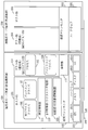
- FIG. 1 shows a system configuration according to the present embodiment.
- the server apparatus 100 and the server apparatus 200 are connected by a LAN (Local Area Network) 300.
- the server apparatus 100 and the server apparatus 200 are different physical computer apparatuses.
- the description will proceed with an example in which the server device 100 is an active server device and the server device 200 is a standby server device.
- the server device 100 is an example of a computer device
- the server device 200 is an example of an external device.
- the fact that the server device 100 is an example of a computer device is expressed as an active server device (computer device), and the fact that the server device 200 is an example of an external device is a standby server device (external device). It expresses.
- the hardware 101 includes, for example, a CPU (Central Processing Unit) 1011, a memory 1012, a disk 1013, and a NIC (Network Interface Card) 1014. Note that the hardware 101 may include other hardware elements.
- a virtual machine monitor 102 operates on the hardware 101, and a host OS 103 and a guest OS 104 operate on the virtual machine monitor 102.
- the guest OS 104 operates using virtual hardware (virtual CPU, virtual memory, virtual disk, virtual NIC, etc.) provided by a virtual machine realized by the virtual machine monitor 102 and the host OS 103.
- the guest OS is an example of a first guest OS.
- the guest OS 104 is an example of the first guest OS, and is shown in parentheses.
- the status of the active guest OS 104 (the context of the guest OS 104) is I / O (Input / Output).
- the server 109 is notified to the standby server device 200 by the synchronization unit 109 at every processing or at a constant cycle, and the guest OS 204 is synchronized with the guest OS 104 (the state of the guest OS 104 and the state of the guest OS 204 match) .
- the guest OS 204 is a guest OS that performs the same operation as the guest OS 104, and is an example of a second guest OS. In FIG. 1, parentheses indicate that the guest OS 204 is an example of a second guest OS.
- synchronization data Data that notifies the latest state of the guest OS 104 is referred to as synchronization data.
- the difference between the synchronization data and the state indicated in the previous synchronization data is indicated.
- the guest OS 204 each time new synchronization data is input, the previous synchronization data is overwritten with the new synchronization data. That is, there is only one synchronization data.
- the synchronization unit 109 operates across the virtual machine monitor 102 and the host OS 103.
- I / O requests include reading data from the disk 1013, writing data to the disk 1013, sending data to the network via the NIC 1014, and receiving data from the network via the NIC 1014.
- the I / O request is a request from the guest OS 104 to the hardware 101. Further, an I / O response from the hardware 101 described later to the guest OS 104 is a response from the hardware 101 to the request.
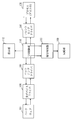
- the flow of I / O processing in the virtual environment is as shown in FIG. 2, and an I / O request from the process 105 is passed to the front-end driver 106 on the guest OS 104 and passes through the virtual machine monitor 102.
- the back-end driver 107 on the host OS 103 passes the I / O request to the real device driver 108, and the real device driver 108 executes the I / O request to the actual hardware 101.
- the I / O response processed by the hardware is returned to the real device driver 108, and the front end driver on the guest OS 104 passes from the real device driver 108 via the back end driver 107 on the host OS 103 and the virtual machine monitor 102. 106, and returned to the process 105 that issued the I / O request.
- an I / O control unit 110 that controls I / O requests and I / O responses between the front-end driver 106 and the back-end driver 107 is arranged on the host OS 103.
- a failure detection unit 111 for inspecting whether or not there is a failure with respect to the I / O response detected by the I / O control unit 110 is arranged.
- a storage unit 112 that temporarily stores a copy of the I / O request from the guest OS 104 is arranged on the virtual machine monitor 102.
- the I / O control unit 110 inputs an I / O request from the front-end driver 106, copies the input I / O request, and copies the I / O request.
- the data is stored in the storage unit 112 and an I / O request is output to the backend driver 107.
- the virtual machine monitor 102 stores a copy of the I / O request from the I / O control unit 110 in a physical storage area associated with the storage unit 112.
- the virtual machine monitor 102 stores a copy of the I / O request in a predetermined address of the memory 1012 or a register of the CPU 1011. Thereafter, as in the case of FIG.
- the I / O request reaches the hardware 101 from the back-end driver 107 via the real device driver 108.
- the hardware 101 outputs an I / O response that is a response to the I / O request to the real device driver 108, and the I / O control unit 110 inputs the I / O response from the back-end driver 107.
- the I / O control unit 110 outputs the input I / O response to the failure detection unit 111.
- the failure detection unit 111 inputs an I / O response from the I / O control unit 110, examines the input I / O response, and if an error message exists in the I / O response, If it is determined that a failure has occurred, the I / O response is discarded, and if there is no error message in the I / O response, the I / O response is forwarded via the I / O control unit 110. Output to the end driver 106. Since the error message of the I / O response is a message for notifying a failure in the hardware 101, when the failure detection unit 111 detects an error message from the I / O response, a failure has occurred in the hardware 101.
- the failure detection unit 111 issues a synchronization instruction to the synchronization unit 109 when a failure of the hardware 101 is detected by detecting an error message of the I / O response.
- the synchronization unit 109 acquires a copy of the I / O request from the storage unit 112 in accordance with the synchronization instruction from the failure detection unit 111, and the guest OS 104 at the time when the failure of the hardware 101 is detected by the failure detection unit 111.
- Information indicating the state is generated.
- Information indicating the state of the guest OS 104 includes the process name of the process 105, the value of the programmable counter of the CPU 1011, the value of the storage area of the memory 1012 allocated to the guest OS 104, and the like.
- the synchronization unit 109 outputs a copy of the I / O request and information indicating the state of the guest OS 104 at the time when the failure of the hardware 101 is detected to the server apparatus 200 as synchronization data.
- the synchronization unit 109 outputs an instruction message that instructs the guest OS 204 to take over the operation performed by the guest OS 104 to the server device 200. Thereafter, in the server device 200, the guest OS 204 becomes the active system and takes over the operation of the guest OS 104.
- the failure detection unit 111 checks the I / O response before the I / O response reaches the guest OS 104, determines whether or not a failure has occurred in the hardware 101, and the failure has occurred in the hardware 101.
- Control is performed so that the I / O response does not reach the guest OS 104 when it occurs. Therefore, the state of the guest OS 104 notified to the guest OS 204 is a state before the detection of the hardware 101 failure, and the guest OS 204 can take over the operation of the guest OS 104 from the state before the detection of the hardware 101 failure.
- the synchronization unit 109 is an example of a takeover control unit
- the I / O control unit 110 is an example of a request management unit.
- the synchronization unit 109 is an example of a takeover control unit and is expressed as a synchronization unit (takeover control unit)
- the I / O control unit 110 is an example of a request management unit (I / O control unit ( Request management department).
- the synchronization unit 109, the I / O control unit 110, and the failure detection unit 111 are programs that operate on the virtual machine monitor 102 or the host OS 103.
- the programs of the synchronization unit 109, the I / O control unit 110, and the failure detection unit 111 are stored in the disk 1013 before execution, and are loaded from the disk 1013 to the memory 1012 and executed by the CPU 1011 before execution.
- the above-described operation is performed.
- the server device 200 has a module configuration example similar to that of the server device 100.
- FIGS. 4 to 7 a series of flow from I / O request generation from the process 105 on the guest OS 104 to I / O response inspection and processing after I / O response inspection. Will be explained. 4 and 5 show the flow of the I / O request transfer process from the process 105 on the guest OS 104 to the hardware 101, and FIGS. 6 and 7 show the process 105 on the guest OS 104 from the hardware 101. The flow of the transfer process of the I / O response to is shown.
- FIG. 4 and FIG. 5 will be described.
- the process 105 on the guest OS 104 outputs an I / O request to the front end driver 106 (S101).
- the front end driver 106 transfers the received I / O request to the back end driver 107 on the host OS 103 via the virtual machine monitor 102 (S102).
- the I / O control unit 110 on the host OS 103 detects the I / O request and performs the processing shown in FIG. 5 (S103).
- the I / O control unit 110 acquires an I / O request from the front-end driver 106, copies the acquired I / O request, outputs a copy of the I / O request to the storage unit 112, and stores the storage unit 112. A copy of the I / O request is stored in (S1031). Next, the I / O control unit 110 transfers the I / O request to the back-end driver 107 of the host OS 103 (S1032).
- the back-end driver 107 receives an I / O request from the I / O control unit 110, and transfers the input I / O request to the real device driver 108 (S104).
- the actual device driver 108 executes control of the hardware 101 based on the I / O request (S105).
- the hardware 101 returns an I / O response to the real device driver 108 on the host OS 103 (S201).
- the actual device driver 108 transfers the received I / O response to the back-end driver 107 (S202).
- the back-end driver 107 transfers the I / O response to the front-end driver 106 on the guest OS 104 (S203).
- the I / O control unit 110 on the host OS 103 detects an I / O response and performs the process shown in FIG. 7 (S204).
- the I / O control unit 110 acquires an I / O response from the back-end driver 107, and transfers the acquired I / O response to the failure detection unit 111 (S2041).
- the failure detection unit 111 inputs an I / O response from the I / O control unit 110 and checks whether there is an error message in the input I / O response (S2042). If the error message is not included in the I / O response, and therefore no failure has occurred in the hardware 101 (NO in S2043), the failure detection unit 111 directly controls the I / O response as I / O control.
- the I / O control unit 110 transfers the I / O response to the front end driver 106 on the guest OS 104 (S2044).
- the I / O control unit 110 deletes the I / O request stored in the storage unit 112 and ends the process (S2045). Then, the front-end driver 106 on the guest OS 104 returns an I / O response to the process 105 (S205).
- an error message is included in the I / O response. For this reason, if a failure has occurred in the hardware 101 (YES in S2043), the failure detection unit 111 has detected the error message. And a synchronization instruction is output to the synchronization unit 109 (S2046).
- the synchronization unit 109 acquires the I / O request stored in the storage unit 112 in S1031 of FIG. 5 from the storage unit 112, and generates information for notifying the state of the active guest OS 104.
- the information for notifying the status of the I / O request and the guest OS 104 becomes the synchronization data, and the synchronization unit 109 transmits the synchronization data to the server device 200 and receives an instruction message instructing the guest OS 204 to take over the operation of the guest OS 104. It transmits to the server apparatus 200 (S2047). As described above, the state of the guest OS 104 immediately before the failure of the hardware 101 is propagated to the guest OS 104 is notified to the server device 200, and the guest OS 204 immediately before the failure of the hardware 101 is propagated to the guest OS 104.
- the synchronization unit 109 forcibly stops the guest OS 104 of the active server device 100 after the synchronization is completed (after transmission of the synchronization data and the instruction message), and takes over the operation of the guest OS 104 to the guest OS 204 on the standby server device 200. (S2048). At this point, the operation of the guest OS 104 is resumed by the guest OS 204 on the synchronization-destination standby server apparatus 200, and the processing is continued without inheriting a hardware failure in the entire system.
- the standby guest OS when a failure occurs in the active hardware, the standby guest OS is synchronized with the state immediately before the hardware failure is propagated to the active guest OS. Can do. As a result, the operation performed on the active guest OS can be normally transferred to the standby guest OS without being affected by the hardware failure of the active system, and the process is smoothly switched to the standby system. be able to. Further, according to the present embodiment, there is an advantage that only one synchronization data is managed. Furthermore, according to the present embodiment, there is an advantage that a mechanism for detecting a hardware failure is unnecessary on the guest OS.
- the I / O control unit 110 and the failure detection unit 111 are included in the host OS, but the I / O control unit 110 and the failure detection unit 111 are included in the virtual machine monitor 102. Good. Further, a configuration in which the I / O control unit 110 is included in the host OS 103 and the failure detection unit 111 is included in the virtual machine monitor 102 may be employed. Further, the I / O control unit 110 may be included in the virtual machine monitor 102, and the failure detection unit 111 may be included in the host OS 103.
- the operating state of the active guest OS is synchronized with the standby server using the virtual environment, and a hardware failure occurs in the active server
- the hardware processing on the guest OS is performed via the virtual machine monitor, the hardware failure is detected by the host OS or the virtual machine monitor, and the hardware failure information is displayed.
- Embodiment 2 The failure detection unit 111 according to the first embodiment detects a failure of the hardware 101 by checking whether there is no error message regarding the I / O response. On the other hand, the failure detection unit 111 may periodically check whether the hardware has no failure or the hardware is operating normally independently of the I / O response. In addition, the failure detection unit 111 checks whether there is a hardware failure or whether the hardware is operating normally when an I / O request from the front-end driver 106 arrives at the I / O control unit 110. You may do it. When a hardware failure is detected, the operations after S2046 in FIG. 7 described in the first embodiment are performed.
- a hardware failure inspection / operation confirmation method by the failure detection unit 111 there are a method of performing communication confirmation by ping or the like regarding the network, and a method of inspecting the NIC up / down.
- the disc for example, S.M. M.M. A. R. T.A. (Self-Monitoring, Analysis and Reporting Technology)
- IPMI Intelligent Platform Management Interface
- the failure detection unit 111 periodically checks for a failure in the hardware 101, a copy of the I / O request may not be stored in the storage unit 112 when the failure in the hardware 101 is detected. If the copy of the I / O request is not stored in the storage unit 112, the synchronization unit 109 synchronizes information indicating the state of the guest OS 104 at the time when the failure of the hardware 101 is detected in S2047 of FIG. The data is output to the server device 200 as data. On the other hand, when a copy of the I / O request is stored in the storage unit 112, the synchronization unit 109 indicates information indicating the state of the guest OS 104 when a failure of the hardware 101 is detected in S2047 of FIG.
- a copy of the I / O request is output to the server device 200 as synchronization data.
- the synchronization unit 109 uses the server apparatus 200 as a synchronous data copy of the I / O request together with information indicating the state of the guest OS 104 at the time when the failure of the hardware 101 is detected in S2047 of FIG. Output to.
- the system configuration according to the present embodiment is also as shown in FIG.
- the standby guest OS is returned to the state immediately before the hardware failure is propagated to the active guest OS. Can be synchronized. As a result, the operation performed on the active guest OS can be normally transferred to the standby guest OS without being affected by the hardware failure of the active system, and the process is smoothly switched to the standby system. be able to. Further, according to the present embodiment, it is possible to detect a hardware failure at a stage where an I / O request is made, and it is possible to detect a hardware failure earlier than in the first embodiment.
- the hardware I / O processing on the guest OS is performed via the virtual machine monitor or the host OS, and the I / O from the guest OS on the host OS or the virtual machine monitor is used. Keep your request temporarily,
- the host OS or virtual machine monitor detects a failure related to hardware I / O, and before the failure information related to the hardware I / O is notified to the guest OS, the host OS or virtual Discard failure information related to hardware I / O on the machine monitor,
- the operating state in which the guest OS issued an I / O request is synchronized with the standby system, and the synchronization data is used to cause a failure on the standby server device.
- the virtual environment synchronization system has been described in which the guest OS can be continuously operated by resuming the operation of the guest OS immediately before the occurrence of the error.
- Embodiment 3 In the first embodiment, a flow from the occurrence of hardware failure to system switching in a system in which one guest OS is arranged in each server device is shown. However, there are a plurality of guest OSs to be synchronized by the software FT. Also good. In other words, the present embodiment targets a system in which two or more guest OSs are arranged in the active server device and a guest OS corresponding to each guest OS in the active server device is arranged in the standby server device. . When a failure occurs in the hardware of the active server device, the synchronization unit of the active server device outputs synchronization data to the standby server device for each guest OS.
- the standby server device takes over the operation of the active guest OS by synchronizing each guest OS with the state of the active guest OS immediately before the failure of the active hardware based on the synchronization data. Make it.
- the storage unit 112 shown in the first embodiment is prepared for each guest OS, and when an error message is detected in the I / O response, the synchronization unit 109 starts from the storage unit 112 for each guest OS. An I / O request for each guest OS is acquired, and synchronization data and instruction data are output for each guest OS.
- the failure detection unit 111 detects a failure of the hardware 101 by a periodic inspection, or when an I / O request reaches the I / O control unit 110.
- the synchronization unit 109 acquires an I / O request for each guest OS from the storage unit 112 for each guest OS, and for each guest OS Synchronous data and instruction data are output. Other operations are as described in the first embodiment and the second embodiment, and a description thereof will be omitted.
- the standby guest OS can be synchronized with the state immediately before the hardware failure is propagated to the active guest OS. it can.
- the standby guest OS can normally take over the operations performed on the active guest OS without being affected by the hardware failure of the active system. And the process can be smoothly switched to the standby system.
- FIG. 8 is a diagram illustrating an example of hardware resources of the server apparatuses 100 and 200 described in the first to third embodiments.
- the configuration in FIG. 8 is merely an example of the hardware configuration of the server apparatuses 100 and 200, and the hardware configuration of the server apparatuses 100 and 200 is not limited to the configuration illustrated in FIG. There may be.
- the server apparatuses 100 and 200 include a CPU 911 (also referred to as a central processing unit, a central processing unit, a processing unit, an arithmetic unit, a microprocessor, a microcomputer, and a processor) that executes a program.
- the CPU 911 receives, for example, a ROM (Read Only Memory) 913, a RAM (Random Access Memory) 914, a communication board 915, a display device 901, a keyboard 902, a mouse 903, a magnetic disk device 920, and a scanner device 907 via a bus 912. Connected and controls these hardware devices.
- the CPU 911 may be connected to an FDD 904 (Flexible Disk Drive), a compact disk device 905 (CDD), and a printer device 906.
- FDD 904 Flexible Disk Drive
- CDD compact disk device
- printer device 906 a storage device such as an optical disk device or a memory card (registered trademark) read / write device may be used.
- the RAM 914 is an example of a volatile memory.
- the storage media of the ROM 913, the FDD 904, the CDD 905, and the magnetic disk device 920 are an example of a nonvolatile memory. These are examples of the storage device.
- a communication board 915, a keyboard 902, a mouse 903, an FDD 904, a scanner device 907, and the like are examples of input devices.
- the communication board 915, the display device 901, the printer device 906, and the like are examples of output devices.
- the communication board 915 is connected to the LAN 300 as shown in FIG.
- the communication board 915 can be connected to, for example, the Internet, a WAN (wide area network), or the like.
- the magnetic disk device 920 stores a virtual machine monitor 921, a host OS 922, a program group 923, and a file group 924.
- the programs in the program group 923 are executed by the CPU 911, the virtual machine monitor 921, and the host OS 922.
- the virtual machine monitor 921 itself includes the function of the host OS 922 or the virtual machine monitor 921 exists in the host OS 922.
- the ROM 913 stores a BIOS (Basic Input Output System) program
- the magnetic disk device 920 stores a boot program.
- BIOS Basic Input Output System
- the server devices 100 and 200 are activated, the BIOS program in the ROM 913 and the boot program in the magnetic disk device 920 are executed, and the virtual machine monitor 921 and the host OS 922 are activated by the BIOS program and the boot program.
- the program group 923 includes programs for realizing the synchronization unit 109, the I / O control unit 110, and the failure detection unit 111 described in the first to third embodiments.
- the file group 924 includes “Judgment of”, “Examination of”, “Detection of”, “Synchronization of”, “Check of”, “ Information, data, signal values, variable values, and parameters that indicate the results of the processing described as “control of”, “setting of”, “selection of”, etc. It is stored as an item.
- the “ ⁇ file” and “ ⁇ database” are stored in a recording medium such as a disk or a memory.
- Information, data, signal values, variable values, and parameters stored in a storage medium such as a disk or memory are read out to the main memory or cache memory by the CPU 911 via a read / write circuit, and extracted, searched, referenced, compared, and calculated.
- the data and signal values are the RAM 914 memory, the FDD 904 flexible disk, the CDD 905 compact disk, and the magnetic field. Recording is performed on a recording medium such as a magnetic disk of the disk device 920, other optical disks, mini disks, DVDs, and the like. Data and signals are transmitted online via a bus 912, signal lines, cables, or other transmission media.
- what is described as “to part” in the description of the first to third embodiments may be “to step”, “to procedure”, and “to process”. That is, what is described as “ ⁇ unit” may be realized by firmware stored in the ROM 913. Alternatively, it may be implemented only by software, or only by hardware such as elements, devices, substrates, and wirings, by a combination of software and hardware, or by a combination of firmware.
- Firmware and software are stored as programs in a recording medium such as a magnetic disk, a flexible disk, an optical disk, a compact disk, a mini disk, and a DVD.
- the program is read by the CPU 911 and executed by the CPU 911. In other words, the program causes the computer to function as the “unit” in the first to third embodiments. Alternatively, the computer executes the procedure and method of “unit” in the first to third embodiments. It is also possible to grasp the operations of the server apparatuses 100 and 200 described in the first to third embodiments as, for example, a data processing method.
- the server devices 100 and 200 described in the first to third embodiments include a CPU as a processing device, a memory as a storage device, a magnetic disk, a keyboard as an input device, a mouse, a communication board, and a display device as an output device, A computer provided with a communication board or the like, and implements the functions indicated as “ ⁇ units” using the processing device, storage device, input device, and output device as described above.
- server device 101 hardware, 102 virtual machine monitor, 103 host OS, 104 guest OS, 105 process, 106 front end driver, 107 back end driver, 108 real device driver, 109 synchronization unit, 110 I / O control unit, 111 failure detection unit, 112 storage unit, 200 server device, 201 hardware, 202 virtual machine monitor, 203 host OS, 204 guest OS, 300 LAN, 1011 CPU, 1012 memory, 1013 disk, 1014 NIC.
Landscapes
- Engineering & Computer Science (AREA)
- Theoretical Computer Science (AREA)
- Software Systems (AREA)
- Physics & Mathematics (AREA)
- General Engineering & Computer Science (AREA)
- General Physics & Mathematics (AREA)
- Quality & Reliability (AREA)
- Hardware Redundancy (AREA)
Abstract
I/O制御部110は、ゲストOS104からのI/Oリクエストを入力し、I/Oリクエストのコピーを保存部112に格納し、ハードウェア101がI/Oリクエストに対するI/Oレスポンスを出力した際に、障害検知部111がI/Oレスポンスを検査し、I/Oレスポンスにエラーメッセージがある場合に、ハードウェア101に障害が発生していると判断し、I/Oレスポンスを破棄し、同期部109に同期指示を行い、同期部109は、保存部112内のI/Oリクエストのコピーと、ハードウェア101の障害が検知された時点でのゲストOS104の状態を示す情報をサーバ装置200に出力し、サーバ装置200では、同期部109からの情報をもとに、ゲストOS204をゲストOS104と同じ状態にし、ゲストOS204がゲストOS104の動作を引き継ぐ。
Description
本発明は、冗長構成をとる仮想計算機システムを管理する技術に関する。
仮想化技術を応用し、例えば、二つの仮想マシンを二つのサーバ装置(物理計算機装置)上で構築し、二つの仮想マシンを同期させて、仮想マシンを二重化し、ソフトウェア的にFT(Fault Tolerant:耐障害性)を実現する技術(以下、ソフトウェアFTと呼ぶ)がある(例えば、非特許文献1、非特許文献2)。
このソフトウェアFTの環境では、運用系のサーバ装置で動作するゲストOS(Operating System)の状態(メモリ、ディスク等)を動作ごと、または、ある一定周期ごとに待機系のサーバ装置上へ同期(コピー)しておく。
そして、運用系のサーバ装置で障害が発生した場合に、待機系のサーバ装置上にコピーしておいたゲストOSの状態から、ゲストOSの動作を待機系のサーバ装置において再開させることで、すばやい動作の再開が可能となる。
そして、運用系のサーバ装置で障害が発生した場合に、待機系のサーバ装置上にコピーしておいたゲストOSの状態から、ゲストOSの動作を待機系のサーバ装置において再開させることで、すばやい動作の再開が可能となる。
しかし、従来のソフトウェアFT環境では、運用系のサーバ装置で発生したハードウェア故障に起因するディスクやネットワークなどのI/O(Input/Output)エラーに関する内部処理まで同期対象になりうる。
つまり、ハードウェア故障に起因するディスクやネットワークなどのI/Oエラーに関する内部処理までが、待機系のサーバ装置にコピーされることになる。
そして、運用系のサーバ装置にハードウェア故障が発生した場合に、ハードウェア故障に起因するI/Oエラーに関する内部処理が待機系のサーバ装置にコピーされ、また、待機系のゲストOSが運用系のゲストOSの動作を引き継ぐ。
このとき、待機系のゲストOSでも、同様の状態(例えば、I/Oリトライ処理中の状態や、I/Oエラーが返された状態)で動作が異常になり、結果として、両系で異常になる可能性がある。
つまり、ハードウェア故障に起因するディスクやネットワークなどのI/Oエラーに関する内部処理までが、待機系のサーバ装置にコピーされることになる。
そして、運用系のサーバ装置にハードウェア故障が発生した場合に、ハードウェア故障に起因するI/Oエラーに関する内部処理が待機系のサーバ装置にコピーされ、また、待機系のゲストOSが運用系のゲストOSの動作を引き継ぐ。
このとき、待機系のゲストOSでも、同様の状態(例えば、I/Oリトライ処理中の状態や、I/Oエラーが返された状態)で動作が異常になり、結果として、両系で異常になる可能性がある。
これに対し、特許文献1に記載の技術では、ゲストOSの稼動状態と、定期的に取得するゲストOS状態(特許文献1ではスナップショットデータとしているが、本明細書では、以降は同期データと称する)を関連付けて保存する。
更に、特許文献1の技術では、運用系のサーバ装置で故障が発生した場合には、該当故障が発生していないゲストOS稼動状態までさかのぼって同期データを選択し、選択した同期データを用いて待機系のサーバ装置においてゲストOSの動作を再開させる。
このようにして、特許文献1の技術では、故障による処理異常を継承させることなくゲストOSを切り替えることを可能としている。
更に、特許文献1の技術では、運用系のサーバ装置で故障が発生した場合には、該当故障が発生していないゲストOS稼動状態までさかのぼって同期データを選択し、選択した同期データを用いて待機系のサーバ装置においてゲストOSの動作を再開させる。
このようにして、特許文献1の技術では、故障による処理異常を継承させることなくゲストOSを切り替えることを可能としている。
Remus: High Availability via Asynchronous Virtual Machine Replication、http://nss.cs.ubc.ca/remus/
Kemari: 仮想マシン間の同期による耐故障クラスタリング、情報処理学会論文誌 コンピューティングシステム、Vol.3、No.1(Mar.2010)
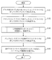
しかし、特許文献1では故障を検知する機構をゲストOS上に配置しているため、故障検知にタイムラグがあり、結局はゲストOSへハードウェア故障状態が伝播した状態を待機系のサーバ装置に通知することになる。
このため、前述したように、待機系のゲストOSが動作を開始しても、待機系のサーバ装置においてハードウェア障害が発生したのと同様の状態になってしまう。
また、特許文献1の方法では、複数の同期データを管理しておく必要があり、データ量が増大する。
さらに、故障検知のタイミングによっては、相当量の時間をさかのぼった同期データから待機系のゲストOSが動作を再開させなければならない場合がある。
このため、前述したように、待機系のゲストOSが動作を開始しても、待機系のサーバ装置においてハードウェア障害が発生したのと同様の状態になってしまう。
また、特許文献1の方法では、複数の同期データを管理しておく必要があり、データ量が増大する。
さらに、故障検知のタイミングによっては、相当量の時間をさかのぼった同期データから待機系のゲストOSが動作を再開させなければならない場合がある。
この発明は、上記のような課題を解決することを主な目的の一つとしており、ハードウェア障害の影響を受けることなく、待機系においてゲストOSの動作を正常に引き継げるようにすることを主な目的とする。
本発明に係る計算機装置は、
ハードウェアと、前記ハードウェアを用いて実現される仮想マシン上で動作し、前記ハードウェアへのリクエストを発行する第1のゲストOS(Operating System)とを有し、
前記第1のゲストOSと同じ動作を行う第2のゲストOSを有する外部装置に接続されている計算機装置であって、
前記第1のゲストOSにより発行されたリクエストのコピーを所定の記憶領域に格納するリクエスト管理部と、
前記リクエストに対する前記ハードウェアからのレスポンスが前記第1のゲストOSに届く前に前記ハードウェアに障害が発生しているか否かを判断し、前記ハードウェアに障害が発生している場合に前記レスポンスが前記第1のゲストOSに届かないように制御する障害検知部と、
前記障害検知部により前記ハードウェアの障害が検知された場合に、前記記憶領域に格納されている前記リクエストのコピーと前記ハードウェアの障害が検知された時点での前記第1のゲストOSの状態を示す情報を前記外部装置に出力し、前記第1のゲストOSが行っていた動作を前記第2のゲストOSにて引き継ぐよう指示する指示メッセージを前記外部装置に出力する引き継ぎ制御部とを有することを特徴とする。
本発明によれば、ハードウェアからのレスポンスが第1のゲストOSに届く前にハードウェアに障害が発生しているか否かを判断し、ハードウェアに障害が発生している場合にレスポンスが第1のゲストOSに届かないように制御し、ハードウェアの障害が検知された時点での第1のゲストOSの状態を示す情報及びリクエストのコピーを外部装置に出力するため、ハードウェア障害を検知する直前の状態から第2のゲストOSを動作させることができる。
これにより、ハードウェア障害の影響を受けることなく、第2のゲストOSに第1のゲストOSで行われてきた動作を正常に引き継がせることができる。
これにより、ハードウェア障害の影響を受けることなく、第2のゲストOSに第1のゲストOSで行われてきた動作を正常に引き継がせることができる。
実施の形態1.
本実施の形態では、運用系のサーバ装置と待機系のサーバ装置が配置されている構成において、運用系のゲストOS上に故障を検知する機構を加えることなく、運用系のホストOSや仮想マシンモニタでハードウェアの障害を検知し、当該ハードウェア障害に関する障害情報を破棄し、運用系のゲストOSへハードウェアの障害情報が伝播しないようにする。
このようにして、運用系のゲストOSにハードウェア障害を認識させないようにする。
また、本実施の形態では、その後、運用系のサーバ装置から、運用系のゲストOSの状態を通知する同期データ及び運用系のゲストOSの動作を待機系のゲストOSで引き継ぐよう指示する指示データを待機系のサーバ装置に出力する。
そして、待機系のサーバ装置は、同期データを用いて、待機系のゲストOSの状態を運用系のゲストOSの状態と同じにし、運用系のサーバ装置におけるハードウェア障害の影響を受けることなく、待機系のゲストOSが運用系のゲストOSの動作を正常に引き継ぐ。
図1は、本実施の形態に係るシステム構成を示す。
図1に示すように、LAN(Local Area Network)300によりサーバ装置100とサーバ装置200が接続されている。
サーバ装置100とサーバ装置200は、それぞれ異なる物理計算機装置である。
本実施の形態では、サーバ装置100が運用系のサーバ装置であり、サーバ装置200が待機系のサーバ装置である例にて説明を進める。
このため、サーバ装置100が計算機装置の例であり、また、サーバ装置200が外部装置の例である。
図1では、サーバ装置100が計算機装置の例であることを運用系サーバ装置(計算機装置)と表現し、また、サーバ装置200が外部装置の例であることを待機系サーバ装置(外部装置)と表現している。
サーバ装置100とサーバ装置200は、それぞれ異なる物理計算機装置である。
本実施の形態では、サーバ装置100が運用系のサーバ装置であり、サーバ装置200が待機系のサーバ装置である例にて説明を進める。
このため、サーバ装置100が計算機装置の例であり、また、サーバ装置200が外部装置の例である。
図1では、サーバ装置100が計算機装置の例であることを運用系サーバ装置(計算機装置)と表現し、また、サーバ装置200が外部装置の例であることを待機系サーバ装置(外部装置)と表現している。
ハードウェア101(物理ハードウェア)には、例えば、CPU(Central Processing Unit)1011、メモリ1012、ディスク1013及びNIC(Network Interface Card)1014が含まれている。
なお、ハードウェア101には、これら以外のハードウェア要素が含まれていてもよい。
なお、ハードウェア101には、これら以外のハードウェア要素が含まれていてもよい。
ハードウェア101上では仮想マシンモニタ102が動作し、更に、仮想マシンモニタ102上ではホストOS103とゲストOS104が動作している。
ゲストOS104は、仮想マシンモニタ102及びホストOS103により実現される仮想マシンにより提供される仮想ハードウェア(仮想CPU、仮想メモリ、仮想ディスク、仮想NIC等)を利用して動作する。
なお、ゲストOSは、第1のゲストOSの例である。
図1では、ゲストOS104が第1のゲストOSの例であることを括弧書きで示している。
ゲストOS104は、仮想マシンモニタ102及びホストOS103により実現される仮想マシンにより提供される仮想ハードウェア(仮想CPU、仮想メモリ、仮想ディスク、仮想NIC等)を利用して動作する。
なお、ゲストOSは、第1のゲストOSの例である。
図1では、ゲストOS104が第1のゲストOSの例であることを括弧書きで示している。
運用系のサーバ装置100が正常に動作している場合(ハードウェア障害が発生していない場合)には、運用系のゲストOS104の状態(ゲストOS104のコンテキスト)が、I/O(Input/Output)処理ごと、または、一定周期で、同期部109によって待機系のサーバ装置200に通知され、ゲストOS204がゲストOS104と同期している(ゲストOS104の状態とゲストOS204の状態が一致している)。
ゲストOS204は、ゲストOS104と同じ動作を行うゲストOSであり、第2のゲストOSの例である。
図1では、ゲストOS204が第2のゲストOSの例であることを括弧書きで示している。
ゲストOS104の最新状態を通知するデータを同期データという。
同期データは、1つ前の同期データに示されていた状態との差分が示される。
また、ゲストOS204では、新たな同期データが入力される度に、以前の同期データが新たな同期データで上書きされる。すなわち、同期データは1つしかない。
なお、同期部109は、仮想マシンモニタ102とホストOS103に跨って動作する。
ゲストOS204は、ゲストOS104と同じ動作を行うゲストOSであり、第2のゲストOSの例である。
図1では、ゲストOS204が第2のゲストOSの例であることを括弧書きで示している。
ゲストOS104の最新状態を通知するデータを同期データという。
同期データは、1つ前の同期データに示されていた状態との差分が示される。
また、ゲストOS204では、新たな同期データが入力される度に、以前の同期データが新たな同期データで上書きされる。すなわち、同期データは1つしかない。
なお、同期部109は、仮想マシンモニタ102とホストOS103に跨って動作する。
ゲストOS104では通常プロセス105が動作しており、その処理内容によっては、ハードウェア101へI/Oリクエストを出すことになる。
I/Oリクエストの例としては、ディスク1013からのデータの読み出し、ディスク1013へのデータの書き込み、NIC1014を介してのネットワークへのデータ送信、NIC1014を介してのネットワークからのデータの受信がある。
なお、I/Oリクエストは、ゲストOS104からハードウェア101へのリクエストである。
また、後述するハードウェア101からゲストOS104へのI/Oレスポンスは、リクエストに対するハードウェア101からのレスポンスである。
I/Oリクエストの例としては、ディスク1013からのデータの読み出し、ディスク1013へのデータの書き込み、NIC1014を介してのネットワークへのデータ送信、NIC1014を介してのネットワークからのデータの受信がある。
なお、I/Oリクエストは、ゲストOS104からハードウェア101へのリクエストである。
また、後述するハードウェア101からゲストOS104へのI/Oレスポンスは、リクエストに対するハードウェア101からのレスポンスである。
仮想化環境でのI/O処理の流れは図2のようになっており、プロセス105からのI/Oリクエストは、ゲストOS104上のフロントエンドドライバ106へ渡され、仮想マシンモニタ102を経由して、ホストOS103上のバックエンドドライバ107へ渡される。
ホストOS103上のバックエンドドライバ107はI/Oリクエストを実デバイスドライバ108へ渡し、実デバイスドライバ108は実際のハードウェア101へI/Oリクエストを実行する。
ハードウェアで処理されたI/Oレスポンスは、実デバイスドライバ108へ返され、実デバイスドライバ108からホストOS103上のバックエンドドライバ107、仮想マシンモニタ102を経由して、ゲストOS104上のフロントエンドドライバ106へ転送され、I/Oリクエストを出したプロセス105へ返される。
ホストOS103上のバックエンドドライバ107はI/Oリクエストを実デバイスドライバ108へ渡し、実デバイスドライバ108は実際のハードウェア101へI/Oリクエストを実行する。
ハードウェアで処理されたI/Oレスポンスは、実デバイスドライバ108へ返され、実デバイスドライバ108からホストOS103上のバックエンドドライバ107、仮想マシンモニタ102を経由して、ゲストOS104上のフロントエンドドライバ106へ転送され、I/Oリクエストを出したプロセス105へ返される。
本実施の形態では、フロントエンドドライバ106とバックエンドドライバ107間のI/Oリクエスト及びI/Oレスポンスを制御するI/O制御部110をホストOS103上に配置する。
また、I/O制御部110で検知したI/Oレスポンスに関して、障害が無いかどうかを検査する障害検知部111を配置する。
さらに、ゲストOS104からのI/Oリクエストのコピーを一時的に保管しておく保存部112を仮想マシンモニタ102上に配置する。
また、I/O制御部110で検知したI/Oレスポンスに関して、障害が無いかどうかを検査する障害検知部111を配置する。
さらに、ゲストOS104からのI/Oリクエストのコピーを一時的に保管しておく保存部112を仮想マシンモニタ102上に配置する。
より詳しくは、図3に示すように、I/O制御部110は、フロントエンドドライバ106からのI/Oリクエストを入力し、入力したI/Oリクエストをコピーし、I/Oリクエストのコピーを保存部112に格納し、I/Oリクエストをバックエンドドライバ107に出力する。
なお、仮想マシンモニタ102では、I/O制御部110からのI/Oリクエストのコピーを保存部112と関連付けられている物理記憶領域に記憶させる。
仮想マシンモニタ102は、例えば、メモリ1012の所定のアドレス又はCPU1011のレジスタにI/Oリクエストのコピーを記憶させる。
以降は、図2の場合と同様に、I/Oリクエストがバックエンドドライバ107から実デバイスドライバ108を経由してハードウェア101に到達する。
次に、ハードウェア101は、I/Oリクエストに対するレスポンスであるI/Oレスポンスを実デバイスドライバ108に出力し、I/O制御部110はバックエンドドライバ107からI/Oレスポンスを入力する。
そして、I/O制御部110は入力したI/Oレスポンスを障害検知部111に出力する。
障害検知部111は、I/O制御部110からI/Oレスポンスを入力し、入力したI/Oレスポンスを検査し、I/Oレスポンスにエラーメッセージが存在している場合に、ハードウェア101に障害が発生していると判断し、当該I/Oレスポンスを破棄し、I/Oレスポンスにエラーメッセージが存在していない場合に、当該I/OレスポンスをI/O制御部110を介してフロントエンドドライバ106に出力する。
なお、I/Oレスポンスのエラーメッセージはハードウェア101における障害を通知するメッセージであるため、障害検知部111は、I/Oレスポンスからエラーメッセージを検出した場合には、ハードウェア101に障害が発生していると判断できる。
また、障害検知部111は、I/Oレスポンスのエラーメッセージの検出により、ハードウェア101の障害を検知した場合に、同期部109に同期指示を行う。
同期部109では、障害検知部111からの同期指示に従い、保存部112からI/Oリクエストのコピーを取得するとともに、障害検知部111によりハードウェア101の障害が検知された時点でのゲストOS104の状態を示す情報を生成する。
ゲストOS104の状態を示す情報は、プロセス105のプロセス名、CPU1011のプログラマブルカウンタの値、ゲストOS104に割り当てられているメモリ1012の記憶領域の値等である。
同期部109は、I/Oリクエストのコピーと、ハードウェア101の障害が検知された時点でのゲストOS104の状態を示す情報を同期データとしてサーバ装置200に出力する。
また、同期部109は、ゲストOS104が行っていた動作をゲストOS204にて引き継ぐよう指示する指示メッセージをサーバ装置200に出力する。
以降、サーバ装置200では、ゲストOS204が運用系となり、ゲストOS104の動作を引き継ぐ。
このように、障害検知部111がI/OレスポンスがゲストOS104に届く前にI/Oレスポンスを検査し、ハードウェア101に障害が発生しているか否かを判断し、ハードウェア101に障害が発生している場合にI/OレスポンスがゲストOS104に届かないように制御している。
このため、ゲストOS204に通知するゲストOS104の状態は、ハードウェア101障害の検知前の状態であり、ゲストOS204はハードウェア101障害の検知前の状態からゲストOS104の動作を引き継ぐことができる。
本実施の形態では、同期部109は引き継ぎ制御部の例であり、I/O制御部110はリクエスト管理部の例である。
図1では、同期部109が引き継ぎ制御部の例であることを同期部(引き継ぎ制御部)と表現し、I/O制御部110がリクエスト管理部の例であることをI/O制御部(リクエスト管理部)と表現している。
また、上述したように、同期部109、I/O制御部110、障害検知部111は、仮想マシンモニタ102又はホストOS103で動作するプログラムである。
同期部109、I/O制御部110、障害検知部111のプログラムは、例えば、実行前はディスク1013に格納されており、実行に際して、ディスク1013からメモリ1012にロードされ、CPU1011により実行されて、上述の動作が行われる。
なお、図示は省略しているが、サーバ装置200においても、サーバ装置100と同様のモジュール構成例となっている。
次に、本実施の形態に係る動作(ハードウェアに関する故障をゲストOSへ通知しないようにして、待機系へ切り替える動作)を説明する。
具体的には、図4~図7を用いて、ゲストOS104上のプロセス105からのI/Oリクエスト発生から、I/Oレスポンスの検査、I/Oレスポンスの検査後の処置までの一連の流れを説明する。
なお、図4及び図5は、ゲストOS104上のプロセス105からハードウェア101へのI/Oリクエストの転送処理の流れを示し、図6及び図7は、ハードウェア101からゲストOS104上のプロセス105へのI/Oレスポンスの転送処理の流れを示す。
具体的には、図4~図7を用いて、ゲストOS104上のプロセス105からのI/Oリクエスト発生から、I/Oレスポンスの検査、I/Oレスポンスの検査後の処置までの一連の流れを説明する。
なお、図4及び図5は、ゲストOS104上のプロセス105からハードウェア101へのI/Oリクエストの転送処理の流れを示し、図6及び図7は、ハードウェア101からゲストOS104上のプロセス105へのI/Oレスポンスの転送処理の流れを示す。
まず、図4及び図5について説明する。
最初に、ゲストOS104上のプロセス105は、フロントエンドドライバ106に対してI/Oリクエストを出力する(S101)。
フロントエンドドライバ106は、受け取ったI/Oリクエストを仮想マシンモニタ102を経由してホストOS103上のバックエンドドライバ107へ転送する(S102)。
このとき、ホストOS103上のI/O制御部110がI/Oリクエストを検知し、図5に示す処理を行う(S103)。
最初に、ゲストOS104上のプロセス105は、フロントエンドドライバ106に対してI/Oリクエストを出力する(S101)。
フロントエンドドライバ106は、受け取ったI/Oリクエストを仮想マシンモニタ102を経由してホストOS103上のバックエンドドライバ107へ転送する(S102)。
このとき、ホストOS103上のI/O制御部110がI/Oリクエストを検知し、図5に示す処理を行う(S103)。
まず、I/O制御部110はフロントエンドドライバ106からのI/Oリクエストを取得し、取得したI/Oリクエストをコピーし、I/Oリクエストのコピーを保存部112に出力し、保存部112にI/Oリクエストのコピーを格納する(S1031)。
次に、I/O制御部110は、I/OリクエストをホストOS103のバックエンドドライバ107へ転送する(S1032)。
次に、I/O制御部110は、I/OリクエストをホストOS103のバックエンドドライバ107へ転送する(S1032)。
バックエンドドライバ107は、I/O制御部110からI/Oリクエストを入力し、入力したI/Oリクエストを実デバイスドライバ108へ転送する(S104)。
実デバイスドライバ108はI/Oリクエストを元に、ハードウェア101の制御を実行する(S105)。
実デバイスドライバ108はI/Oリクエストを元に、ハードウェア101の制御を実行する(S105)。
以上が、プロセスからハードウェアへのI/Oリクエストまでの流れである。
次に、I/Oリクエストに対するI/Oレスポンスがハードウェアから返されたときの流れを図6及び図7を参照して説明する。
次に、I/Oリクエストに対するI/Oレスポンスがハードウェアから返されたときの流れを図6及び図7を参照して説明する。
まず、ハードウェア101はホストOS103上の実デバイスドライバ108へI/Oレスポンスを返す(S201)。
実デバイスドライバ108は、受け取ったI/Oレスポンスをバックエンドドライバ107へ転送する(S202)。
バックエンドドライバ107はゲストOS104上のフロントエンドドライバ106へI/Oレスポンスを転送する(S203)。
このとき、ホストOS103上のI/O制御部110がI/Oレスポンスを検知し、図7に示す処理を行う(S204)。
実デバイスドライバ108は、受け取ったI/Oレスポンスをバックエンドドライバ107へ転送する(S202)。
バックエンドドライバ107はゲストOS104上のフロントエンドドライバ106へI/Oレスポンスを転送する(S203)。
このとき、ホストOS103上のI/O制御部110がI/Oレスポンスを検知し、図7に示す処理を行う(S204)。
まず、I/O制御部110はバックエンドドライバ107からのI/Oレスポンスを取得し、取得したI/Oレスポンスを障害検知部111へ転送する(S2041)。
障害検知部111は、I/O制御部110からI/Oレスポンスを入力し、入力したI/Oレスポンスにエラーメッセージが無いかチェックする(S2042)。
I/Oレスポンスにエラーメッセージが含まれておらず、このため、ハードウェア101に障害が発生していない場合(S2043でNO)は、障害検知部111はI/OレスポンスをそのままI/O制御部110に転送し、I/O制御部110がI/OレスポンスをゲストOS104上のフロントエンドドライバ106へ転送する(S2044)。
また、I/O制御部110は保存部112で保存しておいたI/Oリクエストを削除し、処理を終了する(S2045)。
そして、ゲストOS104上のフロントエンドドライバ106はプロセス105に対してI/Oレスポンスを返す(S205)。
一方、I/Oレスポンスにエラーメッセージが含まれており、このため、ハードウェア101に障害が発生している場合(S2043でYES)は、障害検知部111はエラーメッセージを検出したI/Oレスポンスを破棄し、同期部109へ同期指示を出力する(S2046)。
同期部109は図5のS1031において保存部112で保存しておいたI/Oリクエストを保存部112から取得し、また、運用系のゲストOS104の状態を通知する情報を生成する。
これらI/OリクエストとゲストOS104の状態を通知する情報が同期データとなり、同期部109は、同期データをサーバ装置200に送信するとともに、ゲストOS204においてゲストOS104の動作を引き継ぐよう指示する指示メッセージをサーバ装置200に送信する(S2047)。
このように、ゲストOS104へハードウェア101の障害が伝播される直前のゲストOS104の状態がサーバ装置200に通知され、ゲストOS204は、ゲストOS104へハードウェア101の障害が伝播される直前のゲストOS104の状態に同期することができる。
次に、同期部109は同期完了後(同期データ及び指示メッセージの送信後)、運用系サーバ装置100のゲストOS104を強制停止させ、待機系サーバ装置200上のゲストOS204にゲストOS104の動作を引き継がせる(S2048)。
この時点で、同期先の待機系サーバ装置200上のゲストOS204でゲストOS104の動作が再開し、システム全体としてはハードウェアの故障を継承することなく処理が継続される。
このように、本実施の形態によれば、運用系のハードウェアで故障が発生した場合に、運用系のゲストOSへハードウェア障害が伝播する直前の状態に待機系のゲストOSを同期させることができる。
これにより、運用系のハードウェア障害の影響を受けることなく、待機系のゲストOSに運用系のゲストOSで行われてきた動作を正常に引き継がせることができ、処理を円滑に待機系へ切り替えることができる。
また、本実施の形態によれば、管理する同期データは1つでよいという利点がある。
更に、本実施の形態によれば、ゲストOS上にハードウェア故障を検知する機構が不要であるという利点がある。
これにより、運用系のハードウェア障害の影響を受けることなく、待機系のゲストOSに運用系のゲストOSで行われてきた動作を正常に引き継がせることができ、処理を円滑に待機系へ切り替えることができる。
また、本実施の形態によれば、管理する同期データは1つでよいという利点がある。
更に、本実施の形態によれば、ゲストOS上にハードウェア故障を検知する機構が不要であるという利点がある。
なお、以上の説明では、I/O制御部110及び障害検知部111は、ホストOSに含まれている、I/O制御部110及び障害検知部111が仮想マシンモニタ102に含まれていてもよい。
また、I/O制御部110がホストOS103に含まれ、障害検知部111が仮想マシンモニタ102に含まれている構成でもよい。
また、I/O制御部110が仮想マシンモニタ102に含まれ、障害検知部111がホストOS103に含まれていている構成でもよい。
また、I/O制御部110がホストOS103に含まれ、障害検知部111が仮想マシンモニタ102に含まれている構成でもよい。
また、I/O制御部110が仮想マシンモニタ102に含まれ、障害検知部111がホストOS103に含まれていている構成でもよい。
以上、本実施の形態では、
ハードウェア異常が発生した場合の二重系システム切替に関し、仮想化環境を用いて運用系ゲストOSの動作状態を待機系サーバ装置と同期しておき、運用系サーバ装置にハードウェア故障が生じた場合に、待機系サーバ装置上にて同期しておいたゲストOSのデータを用いて、動作を再開させる仮想化環境同期システムにおいて、
仮想化環境では、ゲストOS上のハードウェアの処理が仮想マシンモニタを経由して行われることを利用し、ホストOS、または、仮想マシンモニタでハードウェア故障を検知し、そのハードウェア故障情報が該当ゲストOSに通知される前に、ホストOS、または、仮想マシンモニタでハードウェア故障情報通知を止め、
該当ゲストOSがハードウェア故障を検知する前の動作状態を待機系へ同期させ、その同期データを用いて待機系サーバ装置上でゲストOS動作を再開させることで、
該当ゲストOSが継続して動作が可能な仮想化環境同期システムを説明した。
実施の形態2.
実施の形態1の障害検知部111は、I/Oレスポンスに関してエラーメッセージが無いかどうかをチェックしてハードウェア101の障害を検知していた。
これに対し、障害検知部111は、I/Oレスポンスから独立して定期的にハードウェアに故障が無いか、ハードウェアが正常に稼働しているかを検査するようにしてもよい。
また、障害検知部111は、フロントエンドドライバ106からのI/OリクエストがI/O制御部110に到着した段階でハードウェアに故障が無いか、ハードウェアが正常に稼働しているかを検査するようにしてもよい。
そして、ハードウェア故障が検知された場合には、実施の形態1で説明した図7のS2046以降の動作を行うようにする。
ここで、障害検知部111によるハードウェア故障の検査/稼動確認方法としては、ネットワークに関してはping等で疎通確認を実施したり、NICのup/downを検査する方法がある。
また、ディスクに関しては、例えば、S.M.A.R.T.(Self-Monitoring, Analysis and Reporting Technology)情報からディスクの状態を取得して検査する方法がある。
さらに、サーバ装置本体の状態としては、IPMI(Intelligent Platform Management Interface)を用いて、電源、ファン、プロセッサ、メモリ等の故障を検知することも可能である。
なお、障害検知部111が定期的にハードウェア101の故障を検査する場合は、ハードウェア101の障害を検知した時点では保存部112にI/Oリクエストのコピーが格納されていない場合もある。
保存部112にI/Oリクエストのコピーが格納されていない場合は、同期部109は、図7のS2047において、ハードウェア101の障害が検知された時点でのゲストOS104の状態を示す情報を同期データとしてサーバ装置200に出力する。
一方、保存部112にI/Oリクエストのコピーが格納されている場合は、同期部109は、図7のS2047において、ハードウェア101の障害が検知された時点でのゲストOS104の状態を示す情報とともに、I/Oリクエストのコピーを同期データとしてサーバ装置200に出力する。
フロントエンドドライバ106からのI/OリクエストがI/O制御部110に到着した段階で障害検知部111がハードウェア101の故障を検査する場合は、保存部112にI/Oリクエストのコピーが格納されているので、同期部109は、図7のS2047において、ハードウェア101の障害が検知された時点でのゲストOS104の状態を示す情報とともに、I/Oリクエストのコピーを同期データとしてサーバ装置200に出力する。
なお、本実施の形態に係るシステム構成も図1に示す通りである。
このように、本実施の形態によれば、I/Oレスポンスのエラーメッセージ以外によるハードウェア故障検知によっても、運用系のゲストOSへハードウェア障害が伝播する直前の状態に待機系のゲストOSを同期させることができる。
これにより、運用系のハードウェア障害の影響を受けることなく、待機系のゲストOSに運用系のゲストOSで行われてきた動作を正常に引き継がせることができ、処理を円滑に待機系へ切り替えることができる。
また、本実施の形態によれば、I/Oリクエストのあった段階でのハードウェア故障検知が可能であり、実施の形態1に比べて早期にハードウェア故障を検知することができる。
これにより、運用系のハードウェア障害の影響を受けることなく、待機系のゲストOSに運用系のゲストOSで行われてきた動作を正常に引き継がせることができ、処理を円滑に待機系へ切り替えることができる。
また、本実施の形態によれば、I/Oリクエストのあった段階でのハードウェア故障検知が可能であり、実施の形態1に比べて早期にハードウェア故障を検知することができる。
以上、本実施の形態では、
仮想化環境では、ゲストOS上のハードウェアのI/O処理が仮想マシンモニタやホストOSを経由して行われることを利用し、ホストOS、または、仮想マシンモニタでゲストOSからのI/Oリクエストを一時的に保管しておき、
ホストOS、または、仮想マシンモニタでハードウェアのI/Oに関わる障害を検知し、そのハードウェアのI/Oに関わる障害情報が該当ゲストOSに通知される前に、ホストOS、または、仮想マシンモニタでハードウェアのI/Oに関わる障害情報の通知を破棄し、
該当ゲストOSがハードウェアの障害を検知する前の、該当ゲストOSがI/Oリクエストを出した状態の動作状態を待機系へ同期させ、その同期データを用いて待機系サーバ装置上で、故障が発生する直前のゲストOSの動作を再開させることで、該当ゲストOSが継続して動作が可能な仮想化環境同期システムを説明した。
また、本実施の形態では、
ホストOS、または、仮想マシンモニタで検知するハードウェアの障害情報において、
ホストOS、または、仮想マシンモニタでハードウェアの稼動確認を定期的に実施し、それと同時にゲストOSの動作状態を待機系へ同期させ、
ハードウェアが停止している等のハードウェア故障が検知された場合には、直前の同期データを用いて待機系サーバ装置上でゲストOSの動作を再開させることで、該当ゲストOSが継続して動作が可能な仮想化環境同期システムを説明した。
ホストOS、または、仮想マシンモニタで検知するハードウェアの障害情報において、
ホストOS、または、仮想マシンモニタでハードウェアの稼動確認を定期的に実施し、それと同時にゲストOSの動作状態を待機系へ同期させ、
ハードウェアが停止している等のハードウェア故障が検知された場合には、直前の同期データを用いて待機系サーバ装置上でゲストOSの動作を再開させることで、該当ゲストOSが継続して動作が可能な仮想化環境同期システムを説明した。
実施の形態3.
実施の形態1では、各サーバ装置に1つのゲストOSが配置されているシステムにおけるハードウェア故障発生から系切替までの流れを示したが、ソフトウェアFTによる同期対象となるゲストOSは複数であってもよい。
つまり、本実施の形態では、運用系のサーバ装置に2以上のゲストOSが配置され、待機系のサーバ装置に運用系の各ゲストOSに対応するゲストOSが配置されているシステムを対象とする。
そして、運用系のサーバ装置のハードウェアに障害が発生した場合に、運用系のサーバ装置の同期部が、ゲストOSごとに、同期データを待機系のサーバ装置に出力する。
待機系のサーバ装置は、同期データに基づき、各ゲストOSを、運用系のハードウェアに障害が発生する直前の運用系のゲストOSの状態に同期させて、運用系のゲストOSの動作を引き継がせる。
本実施の形態では、実施の形態1で示した保存部112をゲストOSごとに用意し、I/Oレスポンスにエラーメッセージが検出された場合に、同期部109がゲストOSごとの保存部112から各ゲストOSのI/Oリクエストを取得し、ゲストOSごとに同期データ及び指示データを出力する。
また、実施の形態2に示したように、定期的な検査により障害検知部111がハードウェア101の障害を検知した場合、または、I/O制御部110にI/Oリクエストが到達した段階で障害検知部111が検査を実施してハードウェア101の障害を検知した場合にも、同期部109がゲストOSごとの保存部112から各ゲストOSのI/Oリクエストを取得し、ゲストOSごとに同期データ及び指示データを出力する。
その他の動作は、実施の形態1及び実施の形態2に示した通りであり、説明を省略する。
このように、本実施の形態によれば、複数のゲストOSを同期対象とした環境でも、運用系のゲストOSへハードウェア障害が伝播する直前の状態に待機系のゲストOSを同期させることができる。
これにより、複数のゲストOSを同期対象とした環境でも、運用系のハードウェア障害の影響を受けることなく、待機系のゲストOSに運用系のゲストOSで行われてきた動作を正常に引き継がせることができ、処理を円滑に待機系へ切り替えることができる。
これにより、複数のゲストOSを同期対象とした環境でも、運用系のハードウェア障害の影響を受けることなく、待機系のゲストOSに運用系のゲストOSで行われてきた動作を正常に引き継がせることができ、処理を円滑に待機系へ切り替えることができる。
最後に、実施の形態1~3に示したサーバ装置100、200のハードウェア構成例について説明する。
図8は、実施の形態1~3に示すサーバ装置100、200のハードウェア資源の一例を示す図である。
なお、図8の構成は、あくまでもサーバ装置100、200のハードウェア構成の一例を示すものであり、サーバ装置100、200のハードウェア構成は図8に記載の構成に限らず、他の構成であってもよい。
図8は、実施の形態1~3に示すサーバ装置100、200のハードウェア資源の一例を示す図である。
なお、図8の構成は、あくまでもサーバ装置100、200のハードウェア構成の一例を示すものであり、サーバ装置100、200のハードウェア構成は図8に記載の構成に限らず、他の構成であってもよい。
図8において、サーバ装置100、200は、プログラムを実行するCPU911(Central Processing Unit、中央処理装置、処理装置、演算装置、マイクロプロセッサ、マイクロコンピュータ、プロセッサともいう)を備えている。
CPU911は、バス912を介して、例えば、ROM(Read Only Memory)913、RAM(Random Access Memory)914、通信ボード915、表示装置901、キーボード902、マウス903、磁気ディスク装置920、スキャナ装置907と接続され、これらのハードウェアデバイスを制御する。
更に、CPU911は、FDD904(Flexible Disk Drive)、コンパクトディスク装置905(CDD)、プリンタ装置906と接続していてもよい。また、磁気ディスク装置920の代わりに、光ディスク装置、メモリカード(登録商標)読み書き装置などの記憶装置でもよい。
RAM914は、揮発性メモリの一例である。ROM913、FDD904、CDD905、磁気ディスク装置920の記憶媒体は、不揮発性メモリの一例である。これらは、記憶装置の一例である。
通信ボード915、キーボード902、マウス903、FDD904、スキャナ装置907などは、入力装置の一例である。
また、通信ボード915、表示装置901、プリンタ装置906などは、出力装置の一例である。
通信ボード915は、図1に示すように、LAN300に接続される。通信ボード915は、LAN以外にも、例えば、インターネット、WAN(ワイドエリアネットワーク)などに接続することが可能である。
磁気ディスク装置920には、仮想マシンモニタ921、ホストOS922、プログラム群923、ファイル群924が記憶されている。
プログラム群923のプログラムは、CPU911、仮想マシンモニタ921、ホストOS922により実行される。
また、仮想マシンモニタ921自身がホストOS922の機能を含む場合や、ホストOS922内に仮想マシンモニタ921が存在する場合もある。
プログラム群923のプログラムは、CPU911、仮想マシンモニタ921、ホストOS922により実行される。
また、仮想マシンモニタ921自身がホストOS922の機能を含む場合や、ホストOS922内に仮想マシンモニタ921が存在する場合もある。
ROM913には、BIOS(Basic Input Output System)プログラムが格納され、磁気ディスク装置920にはブートプログラムが格納されている。
サーバ装置100、200の起動時には、ROM913のBIOSプログラム及び磁気ディスク装置920のブートプログラムが実行され、BIOSプログラム及びブートプログラムにより仮想マシンモニタ921、ホストOS922が起動される。
サーバ装置100、200の起動時には、ROM913のBIOSプログラム及び磁気ディスク装置920のブートプログラムが実行され、BIOSプログラム及びブートプログラムにより仮想マシンモニタ921、ホストOS922が起動される。
プログラム群923には、実施の形態1~3に示される同期部109、I/O制御部110及び障害検知部111を実現するプログラムが含まれる。
更に、ファイル群924には、実施の形態1~3の説明において、「~の判断」、「~の検査」、「~の検出」、「~の同期」、「~のチェック」、「~の制御」、「~の設定」、「~の選択」等として説明している処理の結果を示す情報やデータや信号値や変数値やパラメータが、「~ファイル」や「~データベース」の各項目として記憶されている。
「~ファイル」や「~データベース」は、ディスクやメモリなどの記録媒体に記憶される。ディスクやメモリなどの記憶媒体に記憶された情報やデータや信号値や変数値やパラメータは、読み書き回路を介してCPU911によりメインメモリやキャッシュメモリに読み出され、抽出・検索・参照・比較・演算・計算・処理・編集・出力・印刷・表示などのCPUの動作に用いられる。
抽出・検索・参照・比較・演算・計算・処理・編集・出力・印刷・表示のCPUの動作の間、情報やデータや信号値や変数値やパラメータは、メインメモリ、レジスタ、キャッシュメモリ、バッファメモリ等に一時的に記憶される。
また、実施の形態1~3で説明しているフローチャートの矢印の部分は主としてデータや信号の入出力を示し、データや信号値は、RAM914のメモリ、FDD904のフレキシブルディスク、CDD905のコンパクトディスク、磁気ディスク装置920の磁気ディスク、その他光ディスク、ミニディスク、DVD等の記録媒体に記録される。また、データや信号は、バス912や信号線やケーブルその他の伝送媒体によりオンライン伝送される。
また、実施の形態1~3の説明において「~部」として説明しているものは「~ステップ」、「~手順」、「~処理」であってもよい。すなわち、「~部」として説明しているものは、ROM913に記憶されたファームウェアで実現されていても構わない。
或いは、ソフトウェアのみ、或いは、素子・デバイス・基板・配線などのハードウェアのみ、或いは、ソフトウェアとハードウェアとの組み合わせ、さらには、ファームウェアとの組み合わせで実施されても構わない。ファームウェアとソフトウェアは、プログラムとして、磁気ディスク、フレキシブルディスク、光ディスク、コンパクトディスク、ミニディスク、DVD等の記録媒体に記憶される。プログラムはCPU911により読み出され、CPU911により実行される。
すなわち、プログラムは、実施の形態1~3の「~部」としてコンピュータを機能させるものである。
あるいは、実施の形態1~3の「~部」の手順や方法をコンピュータに実行させるものである。
また、実施の形態1~3で説明したサーバ装置100、200の動作を例えばデータ処理方法として把握することも可能である。
このように、実施の形態1~3に示すサーバ装置100、200は、処理装置たるCPU、記憶装置たるメモリ、磁気ディスク等、入力装置たるキーボード、マウス、通信ボード等、出力装置たる表示装置、通信ボード等を備えるコンピュータであり、上記したように「~部」として示された機能をこれら処理装置、記憶装置、入力装置、出力装置を用いて実現するものである。
100 サーバ装置、101 ハードウェア、102 仮想マシンモニタ、103 ホストOS、104 ゲストOS、105 プロセス、106 フロントエンドドライバ、107 バックエンドドライバ、108 実デバイスドライバ、109 同期部、110 I/O制御部、111 障害検知部、112 保存部、200 サーバ装置、201 ハードウェア、202 仮想マシンモニタ、203 ホストOS、204 ゲストOS、300 LAN、1011 CPU、1012 メモリ、1013 ディスク、1014 NIC。
Claims (8)
- ハードウェアと、前記ハードウェアを用いて実現される仮想マシン上で動作し、前記ハードウェアへのリクエストを発行する第1のゲストOS(Operating System)とを有し、
前記第1のゲストOSと同じ動作を行う第2のゲストOSを有する外部装置に接続されている計算機装置であって、
前記第1のゲストOSにより発行されたリクエストのコピーを所定の記憶領域に格納するリクエスト管理部と、
前記リクエストに対する前記ハードウェアからのレスポンスが前記第1のゲストOSに届く前に前記ハードウェアに障害が発生しているか否かを判断し、前記ハードウェアに障害が発生している場合に前記レスポンスが前記第1のゲストOSに届かないように制御する障害検知部と、
前記障害検知部により前記ハードウェアの障害が検知された場合に、前記記憶領域に格納されている前記リクエストのコピーと前記ハードウェアの障害が検知された時点での前記第1のゲストOSの状態を示す情報を前記外部装置に出力し、前記第1のゲストOSが行っていた動作を前記第2のゲストOSにて引き継ぐよう指示する指示メッセージを前記外部装置に出力する引き継ぎ制御部とを有することを特徴とする計算機装置。 - 前記計算機装置は、更に、
前記ハードウェアを用いて仮想マシンを実現するホストOSと仮想マシンモニタとを有し、
前記リクエスト管理部と、前記障害検知部と、前記引き継ぎ制御部は、それぞれ、
前記ホストOS及び前記仮想マシンモニタの少なくともいずれかにおいて動作することを特徴とする請求項1に記載の計算機装置。 - 前記障害検知部は、
前記リクエストに対する前記ハードウェアからのレスポンスが前記第1のゲストOSに届く前に前記レスポンスを入力し、入力した前記レスポンスを検査し、前記レスポンスにおいてエラーメッセージが存在する場合に、前記ハードウェアに障害が発生していると判断し、前記レスポンスが前記第1のゲストOSに届かないように制御することを特徴とする請求項1又は2に記載の計算機装置。 - 前記計算機装置は、更に、
前記ハードウェアを用いて仮想マシンを実現するホストOSを有し、
前記ホストOSは、
前記第1のゲストOSに含まれるフロントエンドドライバから出力された前記ハードウェアへのリクエストを入力し、前記ハードウェアからのレスポンスを前記フロントエンドドライバに対して出力するバックエンドドライバを有し、
前記リクエスト管理部は、
前記フロントエンドドライバから前記リクエストを入力し、入力した前記リクエストのコピーを前記記憶領域に格納し、前記リクエストを前記バックエンドドライバに出力し、
前記障害検知部は、
前記バックエンドドライバから出力された前記レスポンスを入力し、入力した前記レスポンスを検査し、前記レスポンスにエラーメッセージが存在している場合に、前記レスポンスを破棄し、前記レスポンスにエラーメッセージが存在していない場合に、前記レスポンスを前記フロントエンドドライバに対して出力することを特徴とする請求項3に記載の計算機装置。 - 前記障害検知部は、
前記リクエストに対する前記ハードウェアからのレスポンスが前記第1のゲストOSに届く前に前記ハードウェアを検査し、前記ハードウェアに障害が発生しているか否かを判断し、前記ハードウェアに障害が発生している場合に前記レスポンスが前記第1のゲストOSに届かないように制御することを特徴とする請求項1~4のいずれかに記載の計算機装置。 - 前記障害検知部は、
一定周期にて、前記ハードウェアを検査し、前記ハードウェアに障害が発生しているか否かを判断し、
前記引き継ぎ制御部は、
前記障害検知部により前記ハードウェアの障害が検知された際に前記記憶領域に前記リクエストのコピーが格納されている場合は、前記記憶領域に格納されている前記リクエストのコピーと前記ハードウェアの障害が検知された時点での前記第1のゲストOSの状態を示す情報を前記外部装置に出力し、
前記障害検知部により前記ハードウェアの障害が検知された際に前記記憶領域に前記リクエストのコピーが格納されていない場合は、前記ハードウェアの障害が検知された時点での前記第1のゲストOSの状態を示す情報を前記外部装置に出力することを特徴とする請求項1~5のいずれかに記載の計算機装置。 - 前記計算機装置は、
前記仮想マシン上で動作する複数の第1のゲストOSを有し、
前記複数の第1のゲストOSに対応させて複数の第2のゲストOSを有する外部装置に接続され、
前記リクエスト管理部は、
各々の第1のゲストOSにより発行されたリクエストのコピーを各々の第1のゲストOSに割り当てられている記憶領域に格納し、
前記引き継ぎ制御部は、
前記障害検知部により前記ハードウェアの障害が検知された場合に、第1のゲストOSごとに、記憶領域に格納されているリクエストのコピーと前記ハードウェアの障害が検知された時点での第1のゲストOSの状態を示す情報を前記外部装置に出力し、第1のゲストOSが行っていた動作を対応する第2のゲストOSにて引き継ぐよう指示する指示メッセージを前記外部装置に出力することを特徴とする請求項1~6のいずれかに記載の計算機装置。 - ハードウェアと、前記ハードウェアを用いて実現される仮想マシン上で動作し、前記ハードウェアへのリクエストを発行する第1のゲストOS(Operating System)とを有し、
前記第1のゲストOSと同じ動作を行う第2のゲストOSを有する外部装置に接続されている計算機装置に、
前記第1のゲストOSにより発行されたリクエストのコピーを所定の記憶領域に格納させ、
前記リクエストに対する前記ハードウェアからのレスポンスが前記第1のゲストOSに届く前に前記ハードウェアに障害が発生しているか否かを判断させ、前記ハードウェアに障害が発生している場合に前記レスポンスが前記第1のゲストOSに届かないように制御させ、
前記ハードウェアの障害が検知された場合に、前記記憶領域に格納されている前記リクエストのコピーと前記ハードウェアの障害が検知された時点での前記第1のゲストOSの状態を示す情報を前記外部装置に対して出力させ、前記第1のゲストOSが行っていた動作を前記第2のゲストOSにて引き継ぐよう指示する指示メッセージを前記外部装置に対して出力させることを特徴とするプログラム。
Priority Applications (2)
| Application Number | Priority Date | Filing Date | Title |
|---|---|---|---|
| PCT/JP2010/070812 WO2012070102A1 (ja) | 2010-11-22 | 2010-11-22 | 計算機装置及びプログラム |
| JP2012545548A JP5335150B2 (ja) | 2010-11-22 | 2010-11-22 | 計算機装置及びプログラム |
Applications Claiming Priority (1)
| Application Number | Priority Date | Filing Date | Title |
|---|---|---|---|
| PCT/JP2010/070812 WO2012070102A1 (ja) | 2010-11-22 | 2010-11-22 | 計算機装置及びプログラム |
Publications (1)
| Publication Number | Publication Date |
|---|---|
| WO2012070102A1 true WO2012070102A1 (ja) | 2012-05-31 |
Family
ID=46145479
Family Applications (1)
| Application Number | Title | Priority Date | Filing Date |
|---|---|---|---|
| PCT/JP2010/070812 Ceased WO2012070102A1 (ja) | 2010-11-22 | 2010-11-22 | 計算機装置及びプログラム |
Country Status (2)
| Country | Link |
|---|---|
| JP (1) | JP5335150B2 (ja) |
| WO (1) | WO2012070102A1 (ja) |
Cited By (2)
| Publication number | Priority date | Publication date | Assignee | Title |
|---|---|---|---|---|
| JP6242557B1 (ja) * | 2017-03-21 | 2017-12-06 | 三菱電機株式会社 | 制御装置および制御プログラム |
| EP3608784A1 (en) * | 2018-08-10 | 2020-02-12 | Yokogawa Electric Corporation | Control system and control apparatus |
Families Citing this family (1)
| Publication number | Priority date | Publication date | Assignee | Title |
|---|---|---|---|---|
| JP2017045084A (ja) * | 2015-08-24 | 2017-03-02 | 日本電信電話株式会社 | 障害検知装置及び障害検知方法 |
Citations (2)
| Publication number | Priority date | Publication date | Assignee | Title |
|---|---|---|---|---|
| JP2008107896A (ja) * | 2006-10-23 | 2008-05-08 | Nec Corp | 物理資源制御管理システム、物理資源制御管理方法および物理資源制御管理用プログラム |
| JP2009245216A (ja) * | 2008-03-31 | 2009-10-22 | Toshiba Corp | 情報処理装置および障害回復方法 |
Family Cites Families (2)
| Publication number | Priority date | Publication date | Assignee | Title |
|---|---|---|---|---|
| JP4544146B2 (ja) * | 2005-11-29 | 2010-09-15 | 株式会社日立製作所 | 障害回復方法 |
| JP2009080692A (ja) * | 2007-09-26 | 2009-04-16 | Toshiba Corp | 仮想計算機システム及び同システムにおけるサービス引き継ぎ制御方法 |
-
2010
- 2010-11-22 WO PCT/JP2010/070812 patent/WO2012070102A1/ja not_active Ceased
- 2010-11-22 JP JP2012545548A patent/JP5335150B2/ja not_active Expired - Fee Related
Patent Citations (2)
| Publication number | Priority date | Publication date | Assignee | Title |
|---|---|---|---|---|
| JP2008107896A (ja) * | 2006-10-23 | 2008-05-08 | Nec Corp | 物理資源制御管理システム、物理資源制御管理方法および物理資源制御管理用プログラム |
| JP2009245216A (ja) * | 2008-03-31 | 2009-10-22 | Toshiba Corp | 情報処理装置および障害回復方法 |
Non-Patent Citations (1)
| Title |
|---|
| YOSHIAKI TAMURA ET AL.: "Kemari: Virtual Machine Synchronization for Fault Tolerance", TRANSACTIONS OF INFORMATION PROCESSING SOCIETY OF JAPAN TRANSACTION, vol. 3, no. 1, 15 April 2010 (2010-04-15), pages 13 - 24 * |
Cited By (3)
| Publication number | Priority date | Publication date | Assignee | Title |
|---|---|---|---|---|
| JP6242557B1 (ja) * | 2017-03-21 | 2017-12-06 | 三菱電機株式会社 | 制御装置および制御プログラム |
| WO2018173123A1 (ja) * | 2017-03-21 | 2018-09-27 | 三菱電機株式会社 | 制御装置および制御プログラム |
| EP3608784A1 (en) * | 2018-08-10 | 2020-02-12 | Yokogawa Electric Corporation | Control system and control apparatus |
Also Published As
| Publication number | Publication date |
|---|---|
| JPWO2012070102A1 (ja) | 2014-05-19 |
| JP5335150B2 (ja) | 2013-11-06 |
Similar Documents
| Publication | Publication Date | Title |
|---|---|---|
| JP5851503B2 (ja) | 高可用性仮想機械環境におけるアプリケーションの高可用性の提供 | |
| US9262257B2 (en) | Providing boot data in a cluster network environment | |
| US8984330B2 (en) | Fault-tolerant replication architecture | |
| CN105683919B (zh) | 用于安全关键软件应用的多核处理器故障检测 | |
| US10929234B2 (en) | Application fault tolerance via battery-backed replication of volatile state | |
| US10185636B2 (en) | Method and apparatus to virtualize remote copy pair in three data center configuration | |
| JP5392594B2 (ja) | 仮想計算機冗長化システム、コンピュータシステム、仮想計算機冗長化方法、及びプログラム | |
| JP2012221321A (ja) | フォールトトレラント計算機システム、フォールトトレラント計算機システムの制御方法、及びフォールトトレラント計算機システムの制御プログラム | |
| US11960366B2 (en) | Live migrating virtual machines to a target host upon fatal memory errors | |
| US20060259815A1 (en) | Systems and methods for ensuring high availability | |
| US7530000B2 (en) | Early detection of storage device degradation | |
| TWI592796B (zh) | 運用於雲端服務之虛擬機之封包察覺式容錯方法及系統、電腦可讀取之記錄媒體及電腦程式產品 | |
| WO2015033433A1 (ja) | ストレージ装置及び障害部位特定方法 | |
| US20250225023A1 (en) | Server maintainability configuration method and apparatus, electronic device and storage medium | |
| CN105579973A (zh) | 冗余系统以及冗余系统管理方法 | |
| US9063854B1 (en) | Systems and methods for cluster raid data consistency | |
| US9798615B2 (en) | System and method for providing a RAID plus copy model for a storage network | |
| JP5335150B2 (ja) | 計算機装置及びプログラム | |
| JP5440073B2 (ja) | 情報処理装置,情報処理装置の制御方法および制御プログラム | |
| JP2011100300A (ja) | 計算機装置及び情報処理方法及びプログラム | |
| JP5880608B2 (ja) | フォールトトレラントサーバ | |
| KR101564144B1 (ko) | 펌웨어 관리 장치 및 방법 | |
| JP5832408B2 (ja) | 仮想計算機システム及びその制御方法 | |
| US12386712B2 (en) | Storage system | |
| JP2017151511A (ja) | 情報処理装置、動作ログ取得方法および動作ログ取得プログラム |
Legal Events
| Date | Code | Title | Description |
|---|---|---|---|
| 121 | Ep: the epo has been informed by wipo that ep was designated in this application |
Ref document number: 10860094 Country of ref document: EP Kind code of ref document: A1 |
|
| WWE | Wipo information: entry into national phase |
Ref document number: 2012545548 Country of ref document: JP |
|
| NENP | Non-entry into the national phase |
Ref country code: DE |
|
| 122 | Ep: pct application non-entry in european phase |
Ref document number: 10860094 Country of ref document: EP Kind code of ref document: A1 |