WO2012063781A1 - Mobile terminal device, base station device, and communication control method - Google Patents
Mobile terminal device, base station device, and communication control method Download PDFInfo
- Publication number
- WO2012063781A1 WO2012063781A1 PCT/JP2011/075608 JP2011075608W WO2012063781A1 WO 2012063781 A1 WO2012063781 A1 WO 2012063781A1 JP 2011075608 W JP2011075608 W JP 2011075608W WO 2012063781 A1 WO2012063781 A1 WO 2012063781A1
- Authority
- WO
- WIPO (PCT)
- Prior art keywords
- subframe
- csi
- protected
- base station
- protected subframe
- Prior art date
Links
Images


Classifications
-
- H—ELECTRICITY
- H04—ELECTRIC COMMUNICATION TECHNIQUE
- H04W—WIRELESS COMMUNICATION NETWORKS
- H04W24/00—Supervisory, monitoring or testing arrangements
- H04W24/10—Scheduling measurement reports ; Arrangements for measurement reports
-
- H—ELECTRICITY
- H04—ELECTRIC COMMUNICATION TECHNIQUE
- H04W—WIRELESS COMMUNICATION NETWORKS
- H04W16/00—Network planning, e.g. coverage or traffic planning tools; Network deployment, e.g. resource partitioning or cells structures
- H04W16/24—Cell structures
- H04W16/32—Hierarchical cell structures
-
- H—ELECTRICITY
- H04—ELECTRIC COMMUNICATION TECHNIQUE
- H04W—WIRELESS COMMUNICATION NETWORKS
- H04W72/00—Local resource management
- H04W72/50—Allocation or scheduling criteria for wireless resources
- H04W72/54—Allocation or scheduling criteria for wireless resources based on quality criteria
- H04W72/542—Allocation or scheduling criteria for wireless resources based on quality criteria using measured or perceived quality
Definitions
- the present invention relates to a mobile terminal apparatus, a base station apparatus, and a communication control method in a next-generation mobile communication system.
- LTE Long Term Evolution
- SC-FDMA Single Carrier Frequency Multiple Access
- the third generation system can achieve a maximum transmission rate of about 2 Mbps on the downlink using generally a fixed bandwidth of 5 MHz.
- a maximum transmission rate of about 300 Mbps on the downlink and about 75 Mbps on the uplink can be realized using a variable band of 1.4 MHz to 20 MHz.
- LTE-A LTE Advanced
- LTE-A LTE Release 10
- Het Net heterogeneous network
- the present invention has been made in view of the above points, and can perform control suitable for interference reduction in a hierarchical network such as HetNet, and can be applied to a mobile terminal device, a base station device, and a next-generation mobile communication system.
- An object is to provide a communication control method.
- the mobile terminal apparatus of the present invention includes: a receiving unit that receives a radio frame of a lower cell in which a protected subframe in which a higher cell suppresses transmission and a non-protected subframe in which a higher cell does not suppress transmission; Two types of reception quality information of the measurement unit that measures the reception quality from the reference signals multiplexed respectively in the subframe and the non-protected subframe, and the protected subframe and the non-protected subframe measured by the measurement unit And a transmission unit that notifies the base station apparatus of
- the base station apparatus of the present invention includes: a transmitting unit that transmits a radio frame of a lower cell in which a protected subframe in which a higher cell suppresses transmission and a non-protected subframe in which a higher cell does not suppress transmission; A CSI-RS arrangement unit that multiplexes CSI-RS, which is one of reference signals, in a predetermined cycle in a subframe or the non-protected subframe, and one reference signal in each subframe constituting the radio frame of the lower cell.
- the present invention it is possible to perform control suitable for interference reduction in a hierarchical network such as HetNet, and it is possible to provide a mobile terminal device, a base station device, and a communication control method compatible with a next-generation mobile communication system.
- FIG. 1 is a diagram for explaining a frequency usage state when mobile communication is performed in the downlink.
- the fundamental frequency block is described as a component carrier.
- the example shown in FIG. 1 is an LTE-A system, which is a first communication system having a relatively wide first system band composed of a plurality of component carriers, and a relatively narrow (here, one component carrier).
- This is a frequency usage state when an LTE system, which is a second communication system having a second system band (which is configured) coexists.
- wireless communication is performed with a variable system bandwidth of 100 MHz or less, and in the LTE system, wireless communication is performed with a variable system bandwidth of 20 MHz or less.
- the system band of the LTE-A system is at least one fundamental frequency region (component carrier: CC) having the system band of the LTE system as a unit. In this way, widening a band by integrating a plurality of fundamental frequency regions is called carrier aggregation.
- component carrier component carrier
- Mobile terminal apparatus having a system band of 20 MHz (base band).
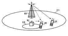
- HetNet a heterogeneous network
- the HetNet is a hierarchical network in which various types of cells such as a pico cell C2 and a femto cell (small cell) are overlaid in addition to the existing macro cell C1 (large cell).
- the base station apparatus (macro base station) B2 of the macro cell C1 that covers a relatively large area is downloaded more than the base station apparatus (pico base station) B1 of the pico cell C2 that covers a relatively narrow area.
- the transmission power is set high.
- HetNet is a hierarchical network in which the pico base station B1 having a small transmission power (and cell area) exists under the macro base station B2 having a large transmission power (and cell area).
- the UE at the cell edge of the pico cell C2 cannot connect to the pico cell C2 even though the UE is located near the pico base station B1.
- the transmission power of the macro base station B2 is larger at the cell edge of the pico cell C2 than the transmission power of the pico base station B1.
- the UE at the cell edge of the pico cell C2 cannot capture the radio frame from the pico base station B1 of the pico cell C1, and connects to the macro cell C1 by capturing the radio frame from the macro base station B2 having higher transmission power. To do. This means that the original area of the pico cell C2 is eroded and reduced by the macro base station B2.
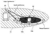
- FIG. 4 shows a conceptual diagram of interference coordination for reducing interference from a macro base station with high transmission power to a pico base station.
- MBSFN Multimedia Broadcast multicast service Single Frequency Network
- the MBSFN subframe is a subframe in which a blank period other than the control channel can be set.
- the interference coordination in the time domain shown in FIG. 4 uses an MBSFN subframe to provide a subframe (ABS: Almost Blank Subframe) serving as a non-transmission section in a radio frame transmitted by the macro base station B2, and
- the radio resource in the ABS section is allocated to the pico UE in the vicinity of the cell edge C2b.
- reference signals Cell specific Reference Signal (CRS), positioning reference signal
- synchronization signals broadcast channels, and paging can be transmitted, but other (data channels, etc.) are not transmitted.
- the UE can connect to the pico cell C2 without being affected by the transmission power from the macro base station B2 in the ABS section. become.
- the transmission power from the pico base station B1 is larger than the transmission power from the macro base station B2, The UE can connect to the pico cell C2.
- the influence of the transmission power from the macro base station B2 is large and the interference is large, but the vicinity of the cell center C2a of the pico cell C2 is from the macro base station B2.
- the interference is small.
- the received SINR increases in the ABS section, but the received SINR decreases in other areas than the ABS section.
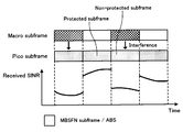
- a pico subframe a section in which a signal transmitted from a pico base station is protected from macro interference is called a protected subframe, and a signal transmitted from a pico base station is protected from macro interference.
- Subframes for which no special measures are taken are called non-protected subframes or normal subframes.
- As a special measure for protecting the CSI-RS of the pico cell from macro interference it is possible to use muting in the macro cell in addition to using the ABS section of the macro cell as described above.
- FIG. 6 is a diagram showing the relationship between protected subframes and non-protected subframes in the cell edge vicinity C2b and their received SINRs. Since the interference from the macro base station B2 is large near the cell edge C2b, the reception SINR is greatly reduced in the non-protected subframe, but the interference from the macro base station B2 is small in the protected subframe, so that the reception SINR is greatly improved. Has been.
- CRS Cell specific Reference Signal
- CQI mobility measurement and channel quality information
- LTE-A LTE-A
- CSI-RS Channel State Information Reference Signal
- the E-UTRAN frame structure defines a radio frame of 10 ms as an aggregate of 20 equally divided 0.5 ms slots, and two consecutive slots are called subframes and are contained within one frame. Ten subframes are accumulated. While CRS is multiplexed in each subframe, CSI-RS is multiplexed in a plurality of subframes with a long cycle of about once.
- the UE located at the cell edge C2b of the pico base station B1 can allocate radio resources to the protected subframe, only the protected subframe may measure the CSI-RS quality and feed back to the pico base station B1. Also, for the UE located in the cell center C2a of the pico base station B1, since radio resources can be allocated to the non-protected subframe, the CSI-RS quality is measured and fed back to the pico base station B1 only in the non-protected subframe. That's fine. Note that interference from the macro base station B2 is limited in the cell center C2a of the pico cell C2. Therefore, there is no significant difference in CSI-RS quality between protected subframes and non-protected subframes. The UE in the cell center C2a can measure the CSI-RS quality multiplexed in the protected subframe or the non-protected subframe and feed it back to the pico base station B1.
- the boundary UE near the boundary between the cell center C2a and the cell edge C2b of the pico base station B1 may be assigned radio resources to the protected subframe and the non-protected subframe.
- the pico base station B1 since the CSI-RS quality is unbalanced between the protected subframe and the nonprotected subframe, the pico base station B1 considers the CSI-RS quality of both the protected subframe and the nonprotected subframe with respect to the boundary UE. And should allocate radio resources.
- the present inventors use the reception quality information (CSI) of the protected subframe.
- CSI reception quality information
- Sufficient UE picocell edge UE
- UE that needs to feed back two types of CSI, that is, a protected subframe and a non-protected subframe (boundary UE), either a protected subframe or a non-protected subframe Focusing on the fact that UEs (pico cell central UEs) that may feed back the CSI of the same are mixed in the pico cell, the present invention has been achieved.
- the present invention provides an optimal CSI feedback method for pico UE radio resource allocation for protected / non-protected subframes using CSI feedback in a pico base station.
- a first aspect of the present invention provides a mobile station apparatus that feeds back two types of CSIs, a protected subframe and a non-protected subframe, to a pico base station.
- processing on the UE side that can be considered for feeding back two types of CSI to the pico base station will be described in detail.
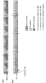
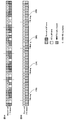
- the ABS pattern in HetNet will be described with reference to FIGS.
- the macro cell and pico cell radio frames are composed of, for example, 10 subframes (# 0 to # 9).
- the figure shows an example in which a radio frame of a pico cell is shifted by two subframes with reference to a radio frame of a macro cell.
- MBSFN subframes can be arranged in 6 subframes # 1, 2, 3 and # 6, 7, 8 in one radio frame.
- MBSFN subframes # 1, 2 and # 7 are set in the ABS section.
- a paging channel for transmitting a synchronization signal (PSS / SSS) is allocated to subframe # 9 of picocell (corresponding to MBSFN subframe # 1 of macrocell), and subframe # 0 of picocell (corresponding to MBSFN subframe # 2 of macrocell) Is assigned a broadcast channel (PBCH) for MIB transmission, and a broadcast channel (PBCH) for SIB1 transmission is assigned to subframe # 5 of picocell (corresponding to MBSFN subframe # 7 of macrocell).
- PBCH broadcast channel
- PBCH broadcast channel
- SIB1 transmission is assigned to subframe # 5 of picocell (corresponding to MBSFN subframe # 7 of macrocell).
- UL HARQ is transmitted at a period of 8 ms in a pico cell.
- a subframe corresponding to the UL HARQ transmission subframe is set in the ABS section in the macro cell radio frame.
- the ABS in the macro cell radio frame is set in addition to the MBSFN subframe.
- the ABS pattern in the radio frame of the macro cell is not uniformly arranged in the time domain, not at regular intervals.
- the ABS pattern shown in FIG. 8 is described as an example for convenience, but the ABS pattern is not limited to one.
- FIG. 9 shows a first example of the CSI feedback method.
- the pico UE performs interference estimation using the CSI-RS in the subframe in which the CSI-RS is multiplexed, and notifies the reception quality information (CSI) to the pico base station.
- CSI reception quality information
- the radio frame transmitted in the macro cell has the same ABS pattern as the ABS pattern shown in FIG.
- the macro base station transmits a radio frame having the ABS pattern shown in FIG. In the ABS section of the radio frame, channel transmission other than the reference signal, synchronization signal, broadcast channel, and paging is stopped, and channel transmission including the reference signal is performed in subframes other than ABS.
- the macro base station transmits CSI-RS (macro CSI-RS) at a cycle of 10 ms. In the radio frame shown in FIG. 9, the macro CSI-RS is transmitted in subframe # 2.
- Subframe # 2 is one of ABS (macro ABS) in a radio frame of a macro cell.
- the pico base station transmits CSI-RS (pico CSI-RS) at the same period (10 ms) as the macro cell.
- the subframe # 0 in which the pico CSI-RS is transmitted corresponds to the subframe # 2 in which the macro CSI-RS is transmitted in the macro cell.
- Subframe # 0 in the picocell radio frame is a protected subframe because it corresponds to macro ABS. That is, an example is shown in which all pico CSI-RSs are transmitted in protected subframes in a pico cell.
- CRS is multiplexed in all subframes # 0 to # 9 in the pico cell radio frame.
- pico subframe # 0 pico CSI-RS and CRS are multiplexed.
- the CSI-RS is arranged so as not to overlap with user data, CRS, and DM-RS in one resource block (12 subcarriers ⁇ 14 OFD symbols) defined by LTE.
- two resource elements adjacent in the time axis direction are assigned as a set to resources that can transmit CSI-RS.
- 40 resource elements are secured as CSI-RS resources.
- a CSI-RS arrangement pattern is set according to the number of CSI-RS ports (number of antennas).
- the pico base station stops transmission of the data channel (PDSCH) for subframe # 0 that transmits pico CSI-RS (muting).
- the macro CSI-RS transmitted in the macro subframe # 2 corresponding to the pico subframe # 0 has a large transmission power.
- the pico UE receives the pico CSI-RS transmitted from the pico base station in subframe # 0, which is a protected subframe, and estimates interference from the pico CSI-RS.
- subframe # 0 in the pico cell is a protected subframe, it is an environment in which interference from the macro base station is small, and accurate interference estimation is realized.
- the pico UE When the CSI of the non-protected subframe is necessary, the pico UE performs interference estimation using CRS in the non-protected subframe.
- the non-protected subframe in the pico cell is, for example, pico subframe # 2 corresponding to subframe # 4 in the macro cell.
- the pico base station signals a control signal for measuring two types of CSI to the pico UE.
- the pico base station notifies the pico UE of a control signal that specifies a CSI measurement subframe.
- the pico UE specifies a non-protected subframe for which interference is estimated using CRS based on a control signal notified from the pico base station, and performs interference estimation using CRS in the non-protected subframe.
- the CSI of the non-protected subframe is fed back to the pico base station.
- the pico UE when interference estimation is performed using the CSI-RS, the pico UE can obtain CSI obtained by interference estimation only in the protected subframe (subframe # 0).
- interference estimation can be performed using CRS in a non-protected subframe (for example, pico subframe # 2). Then, two types of CSI, CSI obtained by interference estimation in the protected subframe (subframe # 0) and CSI obtained by interference estimation in the non-protected subframe, are fed back to the pico base station. Can do.
- FIG. 10 shows a second example of the CSI feedback method.
- the pico UE performs interference estimation using two types of reference signals, CSI-RS and CRS, in one subframe in which CSI-RS is multiplexed. Is fed back to the pico base station.
- the macro base station transmits the macro CSI-RS at a cycle of 10 ms, but the transmission subframe of the macro CSI-RS is subframe # 4 other than the ABS.
- the pico base station transmits pico CSI-RS at the same period as the macro cell using pico subframe # 2 corresponding to macro CSI-RS transmission subframe # 4.
- the macro base station mutes a resource corresponding to the CSI-RS transmission resource of the pico cell in the macro CSI-RS transmission subframe # 4. Muting by the macro base station reduces interference with the pico CSI-RS transmitted by the pico base station.
- user data is arranged corresponding to the CSI-RS of the pico cell C2 in the downlink resource of the macro cell C1.
- user data is arranged corresponding to the CSI-RS of the macro cell C1 in the downlink resource of the pico cell C2.
- the user data of the macro cell C1 constitutes an interference component of the pico CSI-RS in the pico cell C2, and becomes a factor that degrades the channel quality estimation accuracy in the pico UE. Therefore, as shown in FIG. 14B, in the downlink resource block of the macro cell C1, muting resources are set corresponding to the CSI-RS of the pico cell C2.
- the pico CSI-RS transmission subframe # 2 is not an ABS section but functions as a protect subframe.
- the CRS is multiplexed on a resource different from that of the pico CSI-RS.
- the resource in which the CRS is arranged in the pico cell C2 corresponds to a resource that is not muted in the macro cell C1.
- the CRS resource is subject to interference from the macro base station even in the subframe # 2 that is a protected subframe for the pico CSI-RS. Even if it is a protected subframe for the pico CSI-RS, it is recognized as a non-protected subframe for the CRS arranged in the same subframe.
- Pico subframe # 2 if interference estimation is performed using pico CSI-RS, CSI of a protected subframe is obtained, and if interference estimation is performed using CRS, CSI of a non-protected subframe is obtained.
- the pico UE estimates interference by both pico CSI-RS and CRS within the same subframe # 2 of the pico cell, acquires two types of CSI, and feeds back two types of CSI to the pico base station. To do.
- the pico base station notifies the pico UE of information for specifying the subframe position corresponding to the macro ABS.
- the pico UE performs interference estimation using CRS in a subframe corresponding to the macro ABS, and feeds back CSI to the pico base station.
- interference estimation is performed using two types of reference signals, CSI-RS and CRS, and two types of CSI can be fed back to the pico base station. Further, if CSI of a subframe corresponding to a macro ABS that does not receive interference from the macrocell is required, interference estimation is performed using CRS in a pico subframe corresponding to the macro ABS, and CSI can be fed back.
- FIG. 11 shows a third example of the CSI feedback method.
- Each of the macro base station and the pico base station transmits the CSI-RS at a period of 8 ms.
- the macro base station transmits the macro CSI-RS using the macro ABS.
- the pico base station transmits the pico CSI-RS in a pico subframe corresponding to the macro CSI-RS transmission subframe. Since the macro CSI-RS is always transmitted by the macro ABS, the subframe in which the pico CSI-RS is transmitted is a protected subframe.
- the pico UE When the CSI of the non-protected subframe is required, the pico UE performs interference estimation using CRS in the non-protected subframe.
- a subframe shifted from the subframe in which the CSI-RS is measured in the pico cell, for example, to the left by one subframe is a non-protected subframe.
- the pico CSI-RS transmission subframe is # 3, if it is shifted to the right by one subframe, it becomes a non-protected subframe.
- the pico base station mutes the data channel (PDSCH) to be stopped for the subframe in which the pico CSI-RS is transmitted.
- the PDSCH of the pico cell can be prevented from being damaged by the macro CSI-RS having a large transmission power by muting the PDSCH of the pico cell.
- the pico UE receives the pico CSI-RS transmitted from the pico base station in subframes # 1, # 9, # 7, # 5, and # 3 that are protected subframes, and estimates interference. At this time, since subframes # 9, # 7, # 5, # 3, and # 1 in the pico cell are protected subframes, accurate interference estimation is realized in an environment where interference from the macro base station is small.
- the pico UE shifts the CRS measurement subframe from the protected subframe to the non-protected subframe.
- interference estimation is performed using the protected subframe CSI-RS, and interference estimation is performed using the CRS in the non-protected subframe. Then, two types of CSI, CSI obtained by interference estimation in the protected subframe and CSI obtained by interference estimation in the non-protected subframe, can be fed back to the pico base station.
- FIG. 12 shows a fourth example of the CSI feedback method.
- the macro base station and the pico base station transmit CSI-RS at different periods.
- the macro base station transmits the macro CSI-RS in a normal subframe and a protect subframe (ABS) with a period of 8 ms.
- the pico base station transmits pico CSI-RS at a cycle of 10 ms.
- the pico base station transmits some pico CSI-RSs in pico subframes corresponding to the normal subframe of the macro cell, and transmits the remaining pico CSI-RSs to pico subs corresponding to the ABS (protect subframe) of the macro cell. Send in frames.
- the pico UE performs interference estimation using a pico CSI-RS of a pico subframe corresponding to the normal subframe of the macro cell, and uses a pico CSI-RS of a pico subframe corresponding to the ABS (protect subframe) of the macro cell. Estimate interference. As a result, two types of CSI, a normal subframe and a macro ABS (protect subframe), can be acquired using the CSI-RS, and the two types of CSI are fed back to the pico base station.
- the pico base station can recognize whether the subframe position where the pico UE feeds back CSI is a normal subframe or a macro ABS (protect subframe). Therefore, the pico base station can distinguish two types of CSI received from the pico UE into CSI of a normal subframe and CSI of a macro ABS (protect subframe).
- FIG. 13 shows a fifth example of the CSI feedback method.
- the macro base station and the pico base station transmit CSI-RS at different periods.
- the macro base station transmits macro CSI-RS in a normal subframe at a cycle of 10 ms.
- the pico base station transmits pico CSI-RS in a protection subframe corresponding to macro ABS in a cycle of 8 ms.
- the pico CSI-RS can obtain only the CSI of the protected subframe in the interference estimation using the pico CSI-RS.
- CSI of a non-protected subframe is obtained by performing interference estimation using CRS in subframes other than ABS that are shifted from the subframe in which pico CSI-RS is transmitted.
- interference estimation is performed using the protected subframe CSI-RS, and interference estimation is performed using the CRS in the non-protected subframe. Then, two types of CSI, CSI obtained by interference estimation in the protected subframe and CSI obtained by interference estimation in the non-protected subframe, can be fed back to the pico base station.
- a second aspect of the present invention provides a pico base station that signals a control signal for measuring two types of CSI to a pico UE, and further receives a signal from the pico base station and measures two types of CSI.
- a pico base station that signals a control signal for measuring two types of CSI to a pico UE, and further receives a signal from the pico base station and measures two types of CSI.
- the pico base station notifies the pico UE of a time offset value for specifying a subframe for measuring two types of CSI, that is, a protected subframe and a non-protective subframe.
- the signaling of the time offset value in the pico cell can apply higher layer signaling.
- the CSI-RS When performing interference estimation using a reference signal in a subframe in which the CSI-RS is multiplexed and a subframe different from the subframe in which the CSI-RS is multiplexed, the CSI-RS is multiplexed. Signal the time offset value from the subframe to the pico UE.
- interference estimation is performed using CSI-RS in a subframe in which CSI-RS is multiplexed, and the subframe is different from the subframe in which CSI-RS is multiplexed. This is effective when interference estimation is performed using CRS in a frame.
- the pico UE can specify the subframe number in which the CSI-RS is multiplexed from the CSI-RS transmission period (10 ms, 8 ms, etc.) and the subframe offset value.
- the pico base station performs higher layer signaling on the CSI-RS transmission period and subframe offset value.
- the pico UE performs interference estimation using the CRS of the subframe number obtained by adding the time offset value to the subframe number in which the CSI-RS is multiplexed, CSI which is reception quality information obtained by interference estimation can be fed back to the pico base station.
- the pico base station signals a time offset value from subframe # 2 in which CSI-RS is multiplexed to subframe # 0 corresponding to the macro ABS.
- the pico UE performs interference estimation using the pico CSI-RS at the signaled CSI-RS subframe position, and performs interference estimation using the CRS at a subframe position shifted by an offset value from the CSI-RS subframe position.
- the pico base station may notify the type of reference signal for performing interference estimation in a specific subframe.
- Higher layer signaling can be applied to the notification of the type of reference signal used for interference estimation.
- a subframe for transmitting pico CSI-RS is a protected subframe for pico CSI-RS, but is not protected for CRS multiplexed in the same subframe. It may be a subframe. It explicitly notifies that the types of reference signals for performing interference estimation in the subframe are CSI-RS and CRS.
- the subframe in which the CSI-RS is multiplexed may be a subframe that does not correspond to the macro ABS. At this time, for the pico UE at the pico cell edge, only the CSI measured in the protected subframe is required.
- the pico base station signals a control signal in which only the CSI-RS is specified as the reference signal type so that only the measurement using the CSI-RS is performed in the subframe in which the CSI-RS is multiplexed. Also, the control is different from the subframe in which CSI-RS is multiplexed and only CRS is specified as the type of reference signal so that only the measurement using CRS is performed in the subframe corresponding to the macro ABS. Signal the signal.
- the type of reference signal for performing interference estimation may be signaled separately or may be combined and signaled once.
- the pico base station may signal each subframe position to be CSI measurement according to the transmission pattern of the protected subframe and the non-protected subframe.
- the pico base station reports subframe number # 0 as a protected subframe position to be CSI-measured, and subframe number # 2 as a non-protected subframe position to be CSI-measured. Notice.
- the type of reference number used for CSI measurement may be notified together in a protected / non-protected subframe.
- the pico UE has two types of protected subframe and nonprotected subframe. Can be fed back.
- the third aspect of the present invention provides a CSI feedback method capable of reducing CSI feedback overhead when feeding back two types of CSIs, a protected subframe and a non-protected subframe, to a pico base station.
- the pico UE feeds back the CSI of the protected subframe as it is, but feeds back the CSI of the non-protected subframe in the form of a difference value between the protected subframe and the non-protected subframe.
- the overhead can be reduced as compared with the case where the CSI of the protected subframe and the non-protected subframe are fed back independently.
- the pico UE notifies the CSI of the protected subframe as a base, and when the difference between the CSI of the protected subframe and the CSI of the nonprotected subframe exceeds a threshold value, the CSI of the nonprotected subframe is set to the difference value. Notify in the format. As a result, if the CSI quality of the protected subframe and the non-protected subframe is within a predetermined range, the overhead of CSI feedback can be reduced.
- the CSI of the protected subframe and the non-protected subframe may be fed back at different time periods.
- the pico UE feeds back the CSI of the protected subframe with a relatively short time period, and feeds back the CSI of the non-protected subframe with a relatively long time period. Thereby, the total CSI feedback amount can be reduced.
- the pico UE may time average the CSI of the protected subframe and the non-protected subframe independently, and may feed back two types of independently time averaged CSI in parallel. Thereby, the frequency
- the pico base station applies AMC (Adaptive Modulation and Coding) using independent outer loop control, using the two types of CSI of the protected subframe and the non-protected subframe notified from the pico UE.
- AMC Adaptive Modulation and Coding
- the data rate is controlled by switching the modulation method according to the channel state. For example, high-speed modulation (for example, 64QAM) is applied to the outer loop control using the CSI of the protected subframe, and the CSI of the nonprotected subframe. Low speed modulation (for example, QPSK) is applied to the outer loop control using.
- FIG. 15 is an explanatory diagram of the system configuration of the wireless communication system according to the present embodiment.
- the wireless communication system shown in FIG. 15 is a system including, for example, an LTE system or SUPER 3G.
- LTE system Long Term Evolution
- SUPER 3G High Speed Downlink Packet Access
- carrier aggregation in which a plurality of fundamental frequency blocks with the system band of the LTE system as a unit is integrated is used.
- this wireless communication system may be called IMT-Advanced or 4G.
- the wireless communication system 1 includes base station apparatuses 20A, 20B, and 20C and a plurality of mobile terminal apparatuses 10 (10 1 , 10 2 , 10 3) that communicate with the base station apparatuses 20A, 20B, and 20C. ,... 10 n , n is an integer of n> 0).
- the base station devices 20A, 20B, and 20C are connected to the higher station device 30, and the higher station device 30 is connected to the core network 40.
- the mobile terminal apparatus 10 can communicate with the base station apparatuses 20A, 20B, and 20C in the cells C1, C2, and C3.
- the upper station device 30 includes, for example, an access gateway device, a radio network controller (RNC), a mobility management entity (MME), and the like, but is not limited thereto.
- the present invention is applicable to a hierarchical network represented by HetNet.
- HetNet for example, the base station device 20A is a macro base station with a wide cover area and high transmission power, and the base station device 20B is arranged in the cover area and the transmission power is smaller than that of the macro base station. It is a pico base station with a small area.
- Each mobile terminal device (10 1 , 10 2 , 10 3 ,... 10 n ) includes an LTE terminal and an LTE-A terminal.
- the mobile terminal device 10 will be described unless otherwise specified. Proceed.
- the mobile terminal device 10 wirelessly communicates with the base station devices 20A, 20B, and 20C, but more generally, the user equipment (UE including both the mobile terminal device and the fixed terminal device) : User Equipment).
- OFDMA Orthogonal Frequency Division Multiple Access
- SC-FDMA Single Carrier-Frequency Division Multiple Access
- the wireless access method is not limited to this.
- OFDMA is a multi-carrier transmission scheme that performs communication by dividing a frequency band into a plurality of narrow frequency bands (subcarriers) and mapping data to each subcarrier.
- SC-FDMA is a single carrier transmission method that reduces interference between terminals by dividing a system band into bands each consisting of one or continuous resource blocks for each terminal, and a plurality of terminals using different bands. .
- the downlink communication channel includes PDSCH (Physical Downlink Shared Channel) as a downlink data channel shared by each mobile terminal apparatus 10 and downlink L1 / L2 control channels (PDCCH, PCFICH, PHICH). Transmission data and higher control information are transmitted by the PDSCH.
- PDSCH and PUSCH scheduling information and the like are transmitted by PDCCH (Physical Downlink Control Channel).
- the number of OFDM symbols used for PDCCH is transmitted by PCFICH (Physical Control Format Indicator Channel).
- HARQ ACK / NACK for PUSCH is transmitted by PHICH (Physical Hybrid-ARQ Indicator Channel).
- the uplink communication channel has PUSCH (Physical Uplink Shared Channel) as an uplink data channel shared by each mobile terminal apparatus and PUCCH (Physical Uplink Control Channel) as an uplink control channel. Transmission data and higher control information are transmitted by this PUSCH. Also, CSI, which is reception quality information using reference signals (CSI-RS, CRS), downlink radio quality information (CQI: Channel Quality Indicator), ACK / NACK, and the like are transmitted by PUCCH.
- CSI-RS reception quality information using reference signals
- CQI Channel Quality Indicator
- ACK / NACK and the like
- the base station apparatus 20A (for example, a macro base station), 20B (for example, a pico base station), and 20C have the same configuration, and thus will be described as the base station apparatus 20.
- the base station apparatus 20 includes a transmission / reception antenna 201, an amplifier unit 202, a transmission / reception unit (notification unit) 203, a baseband signal processing unit 204, a call processing unit 205, and a transmission path interface 206. Transmission data transmitted from the base station apparatus 20 to the mobile terminal apparatus 10 via the downlink is input from the higher station apparatus 30 to the baseband signal processing unit 204 via the transmission path interface 206.
- the downlink data channel signal is transmitted from the RCP layer, such as PDCP layer processing, transmission data division / combination, RLC (Radio Link Control) retransmission control transmission processing, and MAC (Medium Access).
- RCP layer such as PDCP layer processing, transmission data division / combination, RLC (Radio Link Control) retransmission control transmission processing, and MAC (Medium Access).
- Control Retransmission control, for example, HARQ transmission processing, scheduling, transmission format selection, channel coding, inverse fast Fourier transform (IFFT) processing, and precoding processing are performed.
- transmission processing such as channel coding and inverse fast Fourier transform is performed on the signal of the physical downlink control channel that is the downlink control channel.
- the baseband signal processing unit 204 notifies the mobile terminal apparatus 10 connected to the same cell of the control information for each mobile terminal apparatus 10 to perform wireless communication with the base station apparatus 20 through the broadcast channel.
- Broadcast information for communication in the cell includes, for example, system bandwidth in the uplink or downlink, and root sequence identification information for generating a random access preamble signal in PRACH (Physical Random Access Channel) (Root Sequence Index) etc. are included.
- the transmission / reception unit 203 frequency-converts the baseband signal output from the baseband signal processing unit 204 into a radio frequency band.
- the amplifier unit 202 amplifies the transmission signal subjected to frequency conversion and outputs the amplified transmission signal to the transmission / reception antenna 201.
- a radio frequency signal received by the transmission / reception antenna 201 is amplified by the amplifier unit 202 and is frequency-converted by the transmission / reception unit 203 to be baseband.
- the signal is converted into a signal and input to the baseband signal processing unit 204.
- the baseband signal processing unit 204 performs FFT processing, IDFT processing, error correction decoding, MAC retransmission control reception processing, RLC layer, PDCP layer reception processing on transmission data included in the baseband signal received in the uplink I do.
- the decoded signal is transferred to the higher station apparatus 30 via the transmission path interface 206.
- the call processing unit 205 performs call processing such as communication channel setting and release, state management of the base station device 20, and wireless resource management.
- the mobile terminal apparatus 10 includes a transmission / reception antenna 101, an amplifier unit 102, a transmission / reception unit (reception unit) 103, a baseband signal processing unit 104, and an application unit 105.
- a radio frequency signal received by the transmission / reception antenna 101 is amplified by the amplifier unit 102, frequency-converted by the transmission / reception unit 103, and converted into a baseband signal.
- the baseband signal is subjected to FFT processing, error correction decoding, retransmission control reception processing, and the like by the baseband signal processing unit 104.
- downlink transmission data is transferred to the application unit 105.
- the application unit 105 performs processing related to layers higher than the physical layer and the MAC layer. Also, the broadcast information in the downlink data is also transferred to the application unit 105.
- uplink transmission data is input from the application unit 105 to the baseband signal processing unit 104.
- the baseband signal processing unit 104 performs mapping processing, retransmission control (HARQ) transmission processing, channel coding, DFT processing, and IFFT processing.
- the transmission / reception unit 103 converts the baseband signal output from the baseband signal processing unit 104 into a radio frequency band. Thereafter, the signal is amplified by the amplifier unit 102 and transmitted from the transmission / reception antenna 101.
- HARQ retransmission control
- Each functional block in FIG. 18 is mainly processing contents of the baseband processing unit. Further, the functional blocks shown in FIG. 18 are simplified for explaining the present invention, and the configuration normally provided in the baseband processing unit is provided. Also, in the following description, an index for specifying a resource where CSI-RS is arranged is described as a CSI-RS index.
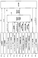
- the pico base station apparatus 20B includes a CRS arrangement unit 210, a CSI-RS arrangement unit 211, a CSI-RS index generation unit 212, a muting resource setting unit 213, and muting resource specifying information.
- a generation unit 219, a notification signal / individual signal generation unit 220, and a transmission / reception unit 203 are included.
- the CRS placement unit 210 places the CRS in the CRS transmission resource in the resource block of each subframe.
- the CRS is arranged in the corresponding resource element on the resource block according to the CRS arrangement pattern in which the CRS arrangement position is determined so that the CRS does not overlap with other control signals.
- the CSI-RS placement unit 211 places the CSI-RS in the corresponding subframe in the radio frame at a CSI-RS transmission cycle (for example, 10 ms or 8 ms).
- CSI-RSs are arranged in pico subframes with a period of 10 ms. Specifically, it is arranged in the CSI-RS transmission resource on the resource block in the target subframe.
- the CSI-RS transmission resource may be determined by a CSI-RS pattern according to the number of CSI-RS ports.
- the CSI-RS index generation unit 212 generates a CSI-RS index corresponding to the CSI-RS transmission resource on the resource block.
- the CSI-RS index generated by the CSI-RS index generation unit 212 is input to the broadcast signal / individual signal generation unit 220 as one of the CSI-RS parameters.
- the muting resource setting unit 213 originally sets a resource corresponding to the CSI-RS transmission resource in the adjacent cell as the muting resource.
- One of mutings in coordinated transmission in HetNet is an operation to stop transmission of PDSCH on the same resource as the resource that transmits CSI-RS in the neighboring cell.
- the neighboring base station of the pico base station is a macro base station. As shown in FIG. 9 and FIG. 11, when the pico base station transmits CSI-RS in the same subframe as the macro cell, the PDSCH transmitted in the pico cell is greatly affected by the influence (interference) of the CSI-RS of the macro cell. Is significantly reduced.
- the reception quality in the pico cell deteriorates due to the influence (interference) of the CSI-RS of the macro cell, there is a possibility that retransmission of PDSCH transmitted in the pico cell is repeated.
- the CSI-RS is transmitted in the same subframe as the subframe in which the CSI-RS is transmitted in the macro cell, it is desirable that the PDSCH is muted in the subframe.
- the muting resource identification information generation unit 214 generates muting resource identification information for muting the PDSCH in a subframe in which the pico CSI-RS is transmitted.
- the muting resource specifying information represents a resource for muting the PDSCH.
- bitmap information or an arrangement pattern of muting resources is generated.
- the CSI-RS parameter generation unit 215 generates parameters such as CSI-RS sequences and transmission power other than the CSI-RS index.
- the CSI-RS parameter generated by the CSI-RS parameter generation unit 215 is input to the broadcast signal / individual signal generation unit 220.
- the muting interval information generation unit 216 generates muting interval information indicating a common transmission interval common to a plurality of cells, corresponding to all subframes for CSI-RS transmission between the cells C1 to C3.
- the muting interval information generation unit 216 generates muting interval information based on the CSI-RS transmission cycle in the own cell and the CSI-RS transmission cycle acquired from the neighboring cell.
- the muting interval information generated by the muting interval information generation unit 216 is input to the notification signal / individual signal generation unit 220.
- the CSI measurement time offset information generation unit 217 generates a time offset value as information for specifying subframes for measuring two types of CSI, a protected subframe and a non-protected subframe. For example, in the example shown in FIG. 9, interference estimation is performed using CSI-RS in subframe # 0 in a radio frame of a pico cell, and interference estimation is performed using CRS in subframe # 2, thereby performing two types of CSI measurements. realizable. If the protected subframe is fixed to subframe # 0 in which CSI-RS is arranged, the non-protective subframe is subframe # 2 shifted by two subframes from subframe # 0. In such a case, the time offset value is set to subframe # 2. Further, the non-protective subframe may be fixed so that the protected subframe can be specified by the time offset value. In other words, the time offset value is a time difference between the protected subframe and the non-protective subframe.
- Interference measurement RS information generation section 218 generates interference measurement RS type information indicating the type of reference signal for performing interference estimation in the target subframe.
- the reference signal type used for interference estimation in the protected subframe and the reference signal type used for interference estimation in the non-protective subframe are notified by the type information of the interference measurement RS.
- pico subframes # 0 and # 9 shown in FIG. 9 are protected subframes, for a pico UE that requires only the CSI of the protected subframe, the pico subframe # 0 includes CSI as an interference measurement RS.
- the 10 is a protected subframe for pico CSI-RS, but is a non-protected subframe for CRS.
- the subframe in which the CSI-RS is multiplexed is a subframe that does not correspond to the macro ABS
- the pico UE at the picocell edge only the CSI measured in the protect subframe is included. is necessary.
- only the CSI-RS is set in the interference measurement RS type information for the subframe in which the CSI-RS is multiplexed
- the CRS is set in the interference measurement RS for the subframe # 0 corresponding to the macro ABS. Set to the type information.
- the interference measurement RS that realizes the CSI measurement using only the protected subframe to the pico UE at the pico cell edge.
- CSI for both a protected subframe and a non-protected subframe is required.
- two types of CSI-RS and CRS are set in the interference measurement RS type information for the subframe in which CSI-RS is multiplexed.
- CSI measurement of a protected subframe can be realized using CSI-RS
- CSI measurement of a non-protected subframe can be realized using CRS in the same subframe.
- the type information of the interference measurement RS generated by the interference measurement RS information generation unit 218 is input to the notification signal / individual signal generation unit 220.
- the CSI measurement subframe information generation unit 214 generates CSI measurement subframe information for specifying a subframe position to be a CSI measurement target.
- the CSI measurement time offset information generation unit 217 uses the time offset value to specify the subframe position that is the CSI measurement target. However, the CSI measurement subframe information generation unit 214 sets the CSI measurement target subframe at the subframe position. Specify directly. As the reference signal type used for interference estimation in the signaled subframe, the type information of the RS for interference measurement can be used.
- the CSI measurement subframe information generated by the CSI measurement subframe information generation unit 214 is input to the broadcast signal / individual signal generation unit 220.
- the broadcast signal / individual signal generation unit 220 includes a CSI-RS index, muting resource specifying information, muting interval information, other CSI-RS parameters, CSI measurement time offset information, interference measurement RS information, and CSI measurement sub
- a broadcast signal or an individual signal including frame information is generated.
- Information (for example, CSI-RS index and other CSI-RS parameters) to be notified to the mobile terminal apparatus 10 for the entire pico cell is generated by a broadcast signal, and information to be individually notified to each mobile terminal apparatus 10 (muting) Resource identification information, CSI measurement time offset information, interference measurement RS information, and CSI measurement subframe information) are generated as individual signals.
- the notification signal and the individual signal generated by the notification signal / individual signal generation unit 220 perform higher layer signaling.
- the transmission / reception unit 203 maps the CRS, CSI-RS, and broadcast / individual signal to resources and transmits them to the mobile terminal apparatus 10.
- FIG. 19 functional blocks of the mobile terminal apparatus 10 serving as a pico UE will be described.
- Each functional block in FIG. 19 is mainly processing contents of the baseband processing unit. Further, the functional blocks shown in FIG. 19 are simplified for the purpose of explaining the present invention, and the configuration normally provided in the baseband processing unit is provided.
- the mobile terminal apparatus 10 includes a transmission / reception unit 103, an acquisition unit 111, a measurement unit 112, and a user data demodulation unit 113.
- the transceiver 103 receives a control channel (CRS, CSI-RS, etc.) and a broadcast channel (broadcast signal / individual signal) transmitted from the pico base station apparatus 20B and a data channel (user data).
- a control channel CRS, CSI-RS, etc.
- broadcast channel broadcast signal / individual signal
- the acquisition unit 111 analyzes the broadcast signal / individual signal received by the transmission / reception unit 103, and includes a CSI-RS parameter including a CSI-RS index, muting resource identification information, muting interval information, CSI measurement time offset information, Interference measurement RS information and CSI measurement subframe information are acquired.
- a CSI-RS parameter including a CSI-RS index, muting resource identification information, muting interval information, CSI measurement time offset information, Interference measurement RS information and CSI measurement subframe information are acquired.
- the measurement unit 112 performs the following CSI measurement in order to perform two types of CSI feedback of a protected subframe and a non-protected subframe.
- the subframe to be subjected to CSI measurement and the reference signal type used for CSI measurement are signaled using a broadcast signal / individual signal.
- the measurement unit 112 can specify the subframe to be subjected to CSI measurement and the interference measurement RS type in each target subframe by the combination of the CSI measurement time offset information and the interference measurement RS information. For example, if the CSI-RS transmission period and subframe offset value are notified from the pico base station to the mobile terminal apparatus 10, another time for CSI measurement can be obtained by adding a time offset based on the CSI-RS subframe position. Subframes can be specified.
- the measurement unit 112 can specify the subframe to be subjected to CSI measurement and the interference measurement RS type in each target subframe by a combination of the interference measurement RS information and the CSI measurement subframe information. . Since the subframe position used for CSI measurement is directly indicated by the CSI measurement subframe information, the subframe position used for CSI measurement can be specified only by the CSI measurement subframe information. In addition, the measurement unit 112 specifies a CSI-RS resource in which CSI-RS is multiplexed on the resource block using the CSI-RS index, and estimates interference from the CSI-RS.
- interference is estimated from the pico CSI-RS received in subframe # 0, which is a protected subframe. Since subframe # 0 in the pico cell is a protected subframe, it is an environment in which interference from the macro base station is small, and accurate interference estimation is realized. Further, when the CSI of the non-protected subframe is necessary, the location information of the CSI measurement subframe and the interference measurement RS information are notified from the pico base station. For example, CSI measurement using CRS is notified in pico subframe # 2. Measurement section 112 estimates interference from CRS in pico subframe # 2.
- CSI measured using CSI-RS in subframe # 0, which is a protected subframe, and CSI measured using CRS in pico subframe # 2, which is a non-protected subframe, are provided to transmission / reception section 103.
- the transceiver 103 feeds back two types of CSI, a protected subframe and a non-protected subframe, to the pico base station.
- interference estimation is performed from the pico CSI-RS received in subframe # 2, which is a subframe other than the macro ABS, and interference estimation is performed from the CRS received in the same subframe # 2.
- pico subframe # 2 is not an ABS section, since pico CSI-RS resources are muted in a macro cell, it is a protected subframe that is not subject to interference from a macro base station by interference estimation using CSI-RS. CSI is measured. Also, since pico subframe # 2 is not an ABS section, interference other than the pico CSI-RS resource is received from the macro cell. If interference is estimated from the CRS received in the same subframe # 2, CSI as a non-protected subframe receiving interference from the macro base station is measured.
- the transceiver 103 feeds back two types of CSI, a protected subframe and a non-protected subframe, to the pico base station.
- subframe # 0 corresponding to macro ABS is notified from the pico base station as a subframe for CSI measurement, and interference in subframe # 0 is performed.
- CRS is notified as measurement RS.
- interference estimation using CRS in subframe # 0 which is a protected subframe, is performed.
- two types of CSI obtained by performing interference estimation with CSI-RS and CRS in two protected subframes are given to transmission / reception section 103.
- the transceiver 103 feeds back two types of CSI obtained in two protected subframes to the pico base station.
- it may be a protected subframe or a non-protected subframe depending on the transmission position of the pico CSI-RS. If interference estimation using CSI-RS is performed in a subframe that has received pico CSI-RS, as a result, two types of CSI, a protected subframe and a non-protected subframe, are measured.
- the CSI-RS transmission subframe # 1 is notified as a CSI measurement subframe from the pico base station, and only the CSI-RS is notified as an interference measurement RS in the subframe # 1.
- the measurement unit 112 performs interference estimation using CSI-RS in each subframe # 1, thereby measuring two types of CSI, that is, a protected subframe and a non-protected subframe, unevenly. In this way, two types of CSI, a protected subframe and a non-protected subframe, are given to the transmission / reception unit 103.
- the transceiver 103 feeds back two types of CSI to the pico base station.
- the measurement unit 112 may time average the CSI of the protected subframe and the CSI of the non-protected subframe independently. As a result, the CSI measured in the protected subframe protected from interference and the CSI measured in the non-protected subframe with large interference are averaged separately, so that the reception quality can be measured more accurately.
- the user data demodulation unit 113 demodulates user data received via the transmission / reception unit 103.
- the user data demodulation unit 113 demodulates user data by excluding the muting resource indicated by the muting resource specifying information from the target of demodulation processing. This improves the demodulation processing throughput and demodulation accuracy.
- the acquisition unit 111 may perform user data demodulation processing.
- the functional block of a pico base station apparatus is demonstrated.
- symbol is attached
- the pico base station apparatus 20B includes a CRS arranging unit 210, a CSI-RS arranging unit 211, a CSI-RS index generating unit 212, a muting resource setting unit 213, and muting resource specifying information.
- Generation unit 214 CSI-RS parameter generation unit 215, muting interval information generation unit 216, CSI measurement time offset information generation unit 217, interference measurement RS information generation unit 218, and CSI measurement subframe information
- a generation unit 219, a notification signal / individual signal generation unit 220, a user data generation unit 221, a user data arrangement unit 222, and a transmission / reception unit 203 are included.
- a new function related to CSI feedback is added to the user data generation unit 221.
- the user data generation unit 221 conforms to the CSI notification method fed back from the pico UE, and protects and non-protected subframes from CSI information notified in a special compression format for reducing the amount of CSI feedback.
- the two types of CSI are acquired.
- the user data generation unit 221 determines radio resource allocation for each user from the fed back CSI.
- the user data arrangement unit 222 arranges user data according to radio resource allocation for each user.
- the functional block of the mobile terminal apparatus 10 is demonstrated.
- symbol is attached
- the mobile terminal apparatus 10 includes a transmission / reception unit 103, an acquisition unit 111, a measurement unit 112, a user data demodulation unit 113, and a CSI feedback information reduction unit 114.
- the acquisition unit 111 acquires two types of CSI, that is, a protected subframe and a non-protected subframe.
- the CSI feedback information reduction unit 114 obtains a difference value between the two types of CSI of the protected subframe and the nonprotected subframe.
- the difference value between the two types of CSI of the protected subframe and the non-protected subframe is the compressed CSI information.
- the CSI of the protected subframe is transmitted in the normal format, but the CSI of the non-protected subframe is converted into a differential value format of the CSI between the protected subframe and the nonprotected subframe and fed back.
- the CSI of the protected subframe and the compressed CSI information related to the CSI of the non-protected subframe obtained in this way are notified from the transmission / reception unit 103 to the pico location station apparatus 20B.
- the CSI feedback information reduction unit 114 normally feeds back only the CSI of the protected subframe, and when the difference between the CSI of the protected subframe and the CSI of the nonprotected subframe exceeds a threshold value, the nonprotected subframe Is notified in the form of a difference value. That is, the CSI feedback information reduction unit 114 always calculates and monitors the difference value between the CSI of the protected subframe and the CSI of the non-protected subframe, and the difference between the CSI of the protected subframe and the CSI of the non-protected subframe is calculated. When the threshold value is opened, the difference value between the CSI of the protected subframe and the CSI of the non-protected subframe is additionally fed back in addition to the feedback of only the CSI of the protected subframe so far.
- the overhead of CSI feedback can be reduced.
- the CSI feedback information reduction unit 114 may feed back the CSI of the protected subframe and the CSI of the non-protected subframe at different time periods. For example, the CSI of the protected subframe is fed back with a relatively short time period, and the CSI of the non-protected subframe is fed back with a relatively long time period.
- the user data generation unit 221 determines that the CSI of the non-protected subframe notified from the mobile station apparatus 10 is expressed as a difference value from the CSI of the protected subframe.
- the CSI of the non-protected subframe is restored using the CSI of the frame and the difference value notified as the compressed CSI information.
- the user data generation unit 221 considers that the CSI of the non-protected subframe is the same as the CSI of the protected subframe during a period in which only the CSI of the protected subframe is fed back, and the corresponding user is based on the same CSI value. Allocate radio resources for.
- the user data generation unit 221 may apply AMC using independent outer loop control using two types of CSI, that is, a protected subframe and a non-protected subframe.
- AMC independent outer loop control using two types of CSI, that is, a protected subframe and a non-protected subframe.
- high-speed modulation for example, 64QAM
- low-speed modulation for example, QPSK
- the present invention is not limited to the above embodiment, and can be implemented with various modifications.
- the setting position of the muting resource, the number of processing units, the processing procedure, and the number of muting resources in the above description can be appropriately changed and implemented without departing from the scope of the present invention.
- Other modifications can be made without departing from the scope of the present invention.
Abstract
Description
図1は、下りリンクで移動通信が行われる際の周波数使用状態を説明するための図である。なお、以下の説明では基本周波数ブロックをコンポーネントキャリアとして説明する。図1に示す例は、複数のコンポーネントキャリアで構成される相対的に広い第1システム帯域を持つ第1通信システムであるLTE-Aシステムと、相対的に狭い(ここでは、一つのコンポーネントキャリアで構成される)第2システム帯域を持つ第2通信システムであるLTEシステムが併存する場合の周波数使用状態である。LTE-Aシステムにおいては、例えば、100MHz以下の可変のシステム帯域幅で無線通信し、LTEシステムにおいては、20MHz以下の可変のシステム帯域幅で無線通信する。LTE-Aシステムのシステム帯域は、LTEシステムのシステム帯域を一単位とする少なくとも一つの基本周波数領域(コンポーネントキャリア:CC)となっている。このように複数の基本周波数領域を一体として広帯域化することをキャリアアグリゲーションという。 The present invention is applicable to an LTE / LTE-A system that is one of the next generation mobile communication systems. First, an outline of the LTE / LTE-A system will be described.
FIG. 1 is a diagram for explaining a frequency usage state when mobile communication is performed in the downlink. In the following description, the fundamental frequency block is described as a component carrier. The example shown in FIG. 1 is an LTE-A system, which is a first communication system having a relatively wide first system band composed of a plurality of component carriers, and a relatively narrow (here, one component carrier). This is a frequency usage state when an LTE system, which is a second communication system having a second system band (which is configured) coexists. In the LTE-A system, for example, wireless communication is performed with a variable system bandwidth of 100 MHz or less, and in the LTE system, wireless communication is performed with a variable system bandwidth of 20 MHz or less. The system band of the LTE-A system is at least one fundamental frequency region (component carrier: CC) having the system band of the LTE system as a unit. In this way, widening a band by integrating a plurality of fundamental frequency regions is called carrier aggregation.
以下、2種類のCSIをピコ基地局へフィードバックするために考えられるUE側の処理について具体的に説明する。 A first aspect of the present invention provides a mobile station apparatus that feeds back two types of CSIs, a protected subframe and a non-protected subframe, to a pico base station.
Hereinafter, processing on the UE side that can be considered for feeding back two types of CSI to the pico base station will be described in detail.
図9にCSIフィードバック方法の第1例を示す。
図9に示すCSIフィードバック方法は、ピコUEが、CSI-RSが多重されているサブフレームで、CSI-RSを用いて干渉推定し、その受信品質情報(CSI)をピコ基地局へ通知し、CSI-RSが多重されているサブフレームとは異なるサブフレームで、CRSを用いて干渉推定し、その受信品質情報(CSI)をピコ基地局へ通知する。 Specific examples of the CSI feedback method according to the present invention are illustrated in FIGS.
FIG. 9 shows a first example of the CSI feedback method.
In the CSI feedback method shown in FIG. 9, the pico UE performs interference estimation using the CSI-RS in the subframe in which the CSI-RS is multiplexed, and notifies the reception quality information (CSI) to the pico base station. In a subframe different from the subframe in which CSI-RS is multiplexed, interference estimation is performed using CRS, and the reception quality information (CSI) is notified to the pico base station.
ピコUEは、ピコ基地局からプロテクトサブフレームであるサブフレーム#0で送信されたピコCSI-RSを受信し、ピコCSI-RSから干渉推定する。このとき、ピコセルにおけるサブフレーム#0はプロテクトサブフレームであるので、マクロ基地局からの干渉が小さい環境であり、正確な干渉推定が実現される。 The CSI measurement (interference estimation) and CSI feedback in the pico UE will be described.
The pico UE receives the pico CSI-RS transmitted from the pico base station in
図10に示すCSIフィードバック方法は、ピコUEが、CSI-RSが多重されている1つのサブフレーム内において、2種類の参照信号であるCSI-RSとCRSを用いてそれぞれ干渉推定して2種類のCSIをピコ基地局へフィードバックしている。 FIG. 10 shows a second example of the CSI feedback method.
In the CSI feedback method shown in FIG. 10, the pico UE performs interference estimation using two types of reference signals, CSI-RS and CRS, in one subframe in which CSI-RS is multiplexed. Is fed back to the pico base station.
マクロ基地局及びピコ基地局は、それぞれCSI-RSを8ms周期で送信する。このとき、マクロ基地局は、マクロCSI-RSをマクロABSで送信する。ピコ基地局は、ピコCSI-RSを、マクロCSI-RS送信サブフレームに対応したピコサブフレームで送信する。マクロCSI-RSが常にマクロABSで送信されるので、ピコCSI-RSを送信するサブフレームはプロテクトサブフレームとなる。 FIG. 11 shows a third example of the CSI feedback method.
Each of the macro base station and the pico base station transmits the CSI-RS at a period of 8 ms. At this time, the macro base station transmits the macro CSI-RS using the macro ABS. The pico base station transmits the pico CSI-RS in a pico subframe corresponding to the macro CSI-RS transmission subframe. Since the macro CSI-RS is always transmitted by the macro ABS, the subframe in which the pico CSI-RS is transmitted is a protected subframe.
マクロ基地局とピコ基地局とがCSI-RSを異なる周期で送信する。同図に示す例では、マクロ基地局は、マクロCSI-RSをノーマルサブフレーム及びプロテクトサブフレーム(ABS)にて8ms周期で送信する。ピコ基地局は、ピコCSI-RSを10ms周期で送信する。 FIG. 12 shows a fourth example of the CSI feedback method.
The macro base station and the pico base station transmit CSI-RS at different periods. In the example shown in the figure, the macro base station transmits the macro CSI-RS in a normal subframe and a protect subframe (ABS) with a period of 8 ms. The pico base station transmits pico CSI-RS at a cycle of 10 ms.
マクロ基地局とピコ基地局とがCSI-RSを異なる周期で送信する。同図に示す例では、マクロ基地局は、マクロCSI-RSをノーマルサブフレームにて10ms周期で送信する。ピコ基地局は、ピコCSI-RSをマクロABSに対応したプロテクトサブフレームにて8ms周期で送信する。 FIG. 13 shows a fifth example of the CSI feedback method.
The macro base station and the pico base station transmit CSI-RS at different periods. In the example shown in the figure, the macro base station transmits macro CSI-RS in a normal subframe at a cycle of 10 ms. The pico base station transmits pico CSI-RS in a protection subframe corresponding to macro ABS in a cycle of 8 ms.
下りリンクの通信チャネルは、各移動端末装置10で共有される下りデータチャネルとしてのPDSCH(Physical Downlink Shared Channel)と、下りL1/L2制御チャネル(PDCCH、PCFICH、PHICH)とを有する。PDSCHにより、送信データ及び上位制御情報が伝送される。PDCCH(Physical Downlink Control Channel)により、PDSCHおよびPUSCHのスケジューリング情報等が伝送される。PCFICH(Physical Control Format Indicator Channel)により、PDCCHに用いるOFDMシンボル数が伝送される。PHICH(Physical Hybrid-ARQ Indicator Channel)により、PUSCHに対するHARQのACK/NACKが伝送される。 Here, a communication channel in the LTE system will be described.
The downlink communication channel includes PDSCH (Physical Downlink Shared Channel) as a downlink data channel shared by each mobile
送受信部103は、ピコ基地局装置20Bから送信された制御チャネル(CRS、CSI-RS等)および報知チャネル(報知信号/個別信号)を受信すると共にデータチャネル(ユーザデータ)を受信する。 As illustrated in FIG. 19, the mobile
The
図20に示すように、ピコ基地局装置20Bは、CRS配置部210と、CSI-RS配置部211と、CSI-RSインデックス生成部212と、ミューティングリソース設定部213と、ミューティングリソース特定情報生成部214と、CSI-RSパラメータ生成部215と、ミューティング間隔情報生成部216と、CSI測定用時間オフセット情報生成部217と、干渉測定用RS情報生成部218と、CSI測定用サブフレーム情報生成部219と、報知信号/個別信号生成部220と、ユーザデータ生成部221と、ユーザデータ配置部222と、送受信部203とを有している。 With reference to FIG. 20, the functional block of a pico base station apparatus is demonstrated. In addition, the same code | symbol is attached | subjected to the same part as the functional block of the base station apparatus shown in FIG.
As shown in FIG. 20, the pico
図21に示すように、移動端末装置10は、送受信部103と、取得部111と、測定部112と、ユーザデータ復調部113と、CSIフィードバック情報削減部114とを有している。 With reference to FIG. 21, the functional block of the mobile
As illustrated in FIG. 21, the mobile
Claims (17)
- 上位セルが送信抑制しているプロテクトサブフレームと上位セルが送信抑制していないノンプロテクトサブフレームとが混在する下位セルの無線フレームを受信する受信部と、
前記プロテクトサブフレームと前記ノンプロテクトサブフレームにそれぞれ多重された参照信号から受信品質をそれぞれ測定する測定部と、
前記測定部で測定された前記プロテクトサブフレームと前記ノンプロテクトサブフレームの2種類の受信品質情報を基地局装置へ通知する送信部と、
を具備したことを特徴とする移動端末装置。 A receiving unit that receives a radio frame of a lower cell in which a protected subframe in which a higher cell suppresses transmission and a non-protected subframe in which a higher cell does not suppress transmission;
A measurement unit for measuring reception quality from reference signals respectively multiplexed in the protected subframe and the non-protected subframe;
A transmission unit for notifying a base station apparatus of two types of reception quality information of the protected subframe and the non-protected subframe measured by the measurement unit;
A mobile terminal apparatus comprising: - 前記プロテクトサブフレームにおいて受信品質を測定するサブフレーム位置と前記ノンプロテクトサブフレームにおいて受信品質を測定するサブフレーム位置とがそれぞれシグナリングによって設定される請求項1記載の移動端末装置。 The mobile terminal apparatus according to claim 1, wherein a subframe position for measuring reception quality in the protected subframe and a subframe position for measuring reception quality in the non-protected subframe are set by signaling.
- 前記プロテクトサブフレームと前記ノンプロテクトサブフレームの2種類の受信品質を測定するサブフレームを特定するための情報がハイヤレイヤシグナリングされる請求項1記載の移動端末装置。 The mobile terminal apparatus according to claim 1, wherein information for specifying a subframe for measuring two types of reception quality, the protected subframe and the non-protected subframe, is higher layer signalled.
- 前記測定部は、前記参照信号の1つであるCSI-RS(Channel State Information Reference Signal)が多重されたプロテクト又はノンプロテクトサブフレームで、前記CSI-RSを用いた干渉推定によって受信品質を測定し、前記CSI-RSが多重されたサブフレームとは異なるプロテクト又はノンプロテクトサブフレームで、前記参照信号の他の1つであるCRS(Common Reference Signal)を用いた干渉推定によって受信品質を測定し、
前記送信部は、前記CSI-RSと前記CRSで測定された2種類の受信品質情報を基地局装置へ通知する、ことを特徴とする請求項1記載の移動端末装置。 The measurement unit measures reception quality by interference estimation using the CSI-RS in a protected or non-protected subframe in which one of the reference signals, CSI-RS (Channel State Information Reference Signal) is multiplexed. The reception quality is measured by interference estimation using CRS (Common Reference Signal) which is another one of the reference signals in a protected or non-protected subframe different from the subframe in which the CSI-RS is multiplexed,
The mobile terminal apparatus according to claim 1, wherein the transmission section notifies the base station apparatus of two types of reception quality information measured by the CSI-RS and the CRS. - 前記測定部は、前記参照信号の1つであるCSI-RSが多重されたプロテクト又はノンプロテクトサブフレームで、前記CSI-RSを用いた干渉推定によって受信品質を測定し、前記CSI-RSが多重されたサブフレームとは異なるサブフレームであって、前記上位セルがデータチャネルの送信を停止しているサブフレームで、前記CRSを用いた干渉推定によって受信品質を測定する、ことを特徴とする請求項1記載の移動端末装置。 The measurement unit measures reception quality by interference estimation using the CSI-RS in a protected or non-protected subframe in which the CSI-RS that is one of the reference signals is multiplexed, and the CSI-RS is multiplexed. The reception quality is measured by interference estimation using the CRS in a subframe that is different from the received subframe and in which the upper cell stops transmission of a data channel. Item 2. The mobile terminal device according to Item 1.
- 前記測定部は、前記参照信号の1つであるCSI-RSと前記参照信号の他の1つであるCRSとが多重された同一サブフレーム内で、前記CSI-RSと前記CRSとを用いた干渉推定によって2種類の受信品質を測定する、ことを特徴とする請求項1記載の移動端末装置。 The measurement unit uses the CSI-RS and the CRS in the same subframe in which the CSI-RS that is one of the reference signals and the CRS that is the other one of the reference signals are multiplexed. The mobile terminal apparatus according to claim 1, wherein two types of reception quality are measured by interference estimation.
- 前記受信部は、下位セルの基地局装置から通知される報知信号又は個別信号を受信し、
前記測定部は、前記報知信号又は個別信号から取得されるCSI測定対象となるサブフレーム間の時間差分を示す時間オフセット値を用いて、前記プロテクトサブフレーム又は前記ノンプロテクロサブフレームの一方のサブフレーム位置を特定することを特徴とする請求項1記載の移動端末装置。 The receiving unit receives a notification signal or an individual signal notified from a base station apparatus of a lower cell,
The measurement unit uses a time offset value indicating a time difference between subframes to be CSI measurement acquired from the broadcast signal or individual signal, and uses one subframe of the protected subframe or the non-protective subframe. The mobile terminal apparatus according to claim 1, wherein a position is specified. - 前記受信部は、下位セルの基地局装置から通知される報知信号又は個別信号を受信し、
前記測定部は、前記報知信号又は個別信号から取得される干渉測定用参照信号情報にしたがってCSI測定対象となるサブフレームで測定すべき参照信号の種別を特定することを特徴とする請求項1記載の移動端末装置。 The receiving unit receives a notification signal or an individual signal notified from a base station apparatus of a lower cell,
The said measurement part specifies the kind of reference signal which should be measured in the sub-frame used as CSI measurement object according to the reference signal information for interference measurement acquired from the said alerting | reporting signal or an individual signal. Mobile terminal equipment. - 前記受信部は、下位セルの基地局装置から通知される報知信号又は個別信号を受信し、
前記測定部は、前記報知信号又は個別信号から取得されるCSI測定用サブフレーム情報に基づいてCSI測定対象となるサブフレーム位置を特定することを特徴とする請求項1記載の移動端末装置。 The receiving unit receives a notification signal or an individual signal notified from a base station apparatus of a lower cell,
The mobile terminal apparatus according to claim 1, wherein the measurement unit specifies a subframe position that is a CSI measurement target based on CSI measurement subframe information acquired from the broadcast signal or an individual signal. - 上位セルが送信抑制しているプロテクトサブフレームと上位セルが送信抑制していないノンプロテクトサブフレームとが混在する下位セルの無線フレームを送信する送信部と、
前記プロテクトサブフレーム又は前記ノンプロテクトサブフレームに所定周期で参照信号の1つであるCSI-RSを多重するCSI-RS配置部と、
前記下位セルの無線フレームを構成する各サブフレームに参照信号の1つであるCRSを多重するCRS配置部と、
下位セル内で前記無線フレームを受信した移動端末装置からフィードバックされる前記プロテクトサブフレームと前記ノンプロテクトサブフレームの2種類の受信品質情報を受信する受信部と、
前記移動端末装置からフィードバックされる前記2種類の受信品質情報を用いて、当該移動端末装置に対して無線リソースを割り当てるユーザデータ配置部と、
を具備したことを特徴とする基地局装置。 A transmitting unit that transmits a radio frame of a lower cell in which a protected subframe in which a higher cell suppresses transmission and a non-protected subframe in which a higher cell does not suppress transmission;
A CSI-RS arrangement unit that multiplexes CSI-RS, which is one of reference signals, in a predetermined cycle in the protected subframe or the non-protected subframe;
A CRS placement unit that multiplexes CRS, which is one of reference signals, in each subframe constituting the radio frame of the lower cell;
A receiving unit that receives two types of reception quality information of the protected subframe and the non-protected subframe fed back from a mobile terminal device that has received the radio frame in a lower cell;
A user data arrangement unit that allocates radio resources to the mobile terminal device using the two types of reception quality information fed back from the mobile terminal device;
A base station apparatus comprising: - 前記プロテクトサブフレームにおいて受信品質を測定するサブフレーム位置と前記ノンプロテクトサブフレームにおいて受信品質を測定するサブフレーム位置とを前記移動端末装置に対してそれぞれシグナリングする請求項10記載の基地局装置。 The base station apparatus according to claim 10, wherein a subframe position at which reception quality is measured in the protected subframe and a subframe position at which reception quality is measured in the non-protected subframe are respectively signaled to the mobile terminal apparatus.
- 前記プロテクトサブフレームと前記ノンプロテクトサブフレームの2種類の受信品質を測定するサブフレームを特定するための情報を前記移動端末装置に対してハイヤレイヤシグナリングする請求項10記載の基地局装置。 The base station apparatus according to claim 10, wherein higher layer signaling is performed to the mobile terminal apparatus for identifying a subframe for measuring two types of reception quality, the protected subframe and the non-protected subframe.
- CSI測定対象となるサブフレーム間の時間差分を示す時間オフセット値を報知信号又は個別信号で前記移動端末装置へシグナリングすることを特徴とする請求項10記載の基地局装置。 The base station apparatus according to claim 10, wherein a time offset value indicating a time difference between subframes to be subjected to CSI measurement is signaled to the mobile terminal apparatus by a broadcast signal or an individual signal.
- CSI測定対象となるサブフレームで測定すべき参照信号の種別が設定された干渉測定用参照信号情報を報知信号又は個別信号で前記移動端末装置へシグナリングすることを特徴とする請求項10記載の基地局装置。 The base station according to claim 10, wherein the base station is configured to signal the reference signal information for interference measurement in which a type of a reference signal to be measured in a subframe to be measured by CSI is set to the mobile terminal apparatus by a broadcast signal or an individual signal. Station equipment.
- CSI測定対象となるサブフレーム位置を指定したCSI測定用サブフレーム情報を報知信号又は個別信号で前記移動端末装置へシグナリングすることを特徴とする請求項10記載の基地局装置。 The base station apparatus according to claim 10, wherein CSI measurement subframe information specifying a subframe position to be a CSI measurement target is signaled to the mobile terminal apparatus by a broadcast signal or an individual signal.
- 上位セルが送信抑制しているプロテクトサブフレームと上位セルが送信抑制していないノンプロテクトサブフレームとが混在する下位セルの無線フレームを受信するステップと、
前記プロテクトサブフレームと前記ノンプロテクトサブフレームにそれぞれ多重された参照信号から受信品質をそれぞれ測定するステップと、
前記測定された前記プロテクトサブフレームと前記ノンプロテクトサブフレームの2種類の受信品質情報を基地局装置へ通知するステップと、
を具備したことを特徴とするCSIフィードバック方法。 Receiving a radio frame of a lower cell in which a protected subframe in which a higher cell suppresses transmission and a non-protected subframe in which a higher cell does not suppress transmission are mixed;
Measuring reception quality from reference signals multiplexed respectively in the protected subframe and the non-protected subframe;
Notifying the base station apparatus of two types of received quality information of the measured protected subframe and the non-protected subframe;
A CSI feedback method comprising: - 上位セルが送信抑制しているプロテクトサブフレームと上位セルが送信抑制していないノンプロテクトサブフレームとが混在する下位セルの無線フレームを送信するステップと、
前記プロテクトサブフレーム又は前記ノンプロテクトサブフレームに所定周期で参照信号の1つであるCSI-RSを多重するステップと、
前記下位セルの無線フレームを構成する各サブフレームに参照信号の1つであるCRSを多重するステップと、
下位セル内で前記無線フレームを受信した移動端末装置からフィードバックされる前記プロテクトサブフレームと前記ノンプロテクトサブフレームの2種類の受信品質情報を受信するステップと、
前記移動端末装置からフィードバックされる前記2種類の受信品質情報を用いて、当該移動端末装置に対して無線リソースを割り当てるステップと、
を具備したことを特徴とする通信制御方法。 A step of transmitting a radio frame of a lower cell in which a protected subframe in which a higher cell suppresses transmission and a non-protected subframe in which a higher cell does not suppress transmission are mixed;
Multiplexing the CSI-RS, which is one of reference signals, in a predetermined cycle in the protected subframe or the non-protected subframe;
Multiplexing a CRS, which is one of reference signals, in each subframe constituting the radio frame of the lower cell;
Receiving two types of reception quality information of the protected subframe and the non-protected subframe fed back from a mobile terminal apparatus that has received the radio frame in a lower cell;
Allocating radio resources to the mobile terminal device using the two types of reception quality information fed back from the mobile terminal device;
A communication control method characterized by comprising:
Priority Applications (8)
| Application Number | Priority Date | Filing Date | Title |
|---|---|---|---|
| BR112013011452A BR112013011452A2 (en) | 2010-11-08 | 2011-11-07 | mobile terminal handset, base station handset and communication control method |
| RU2013123910/08A RU2575694C2 (en) | 2010-11-08 | 2011-11-07 | Mobile terminal, base station and communication control method |
| KR1020137013754A KR101648858B1 (en) | 2010-11-08 | 2011-11-07 | Mobile terminal device, base station device, and communication control method |
| EP11839770.2A EP2640114A4 (en) | 2010-11-08 | 2011-11-07 | Mobile terminal device, base station device, and communication control method |
| MX2013005148A MX2013005148A (en) | 2010-11-08 | 2011-11-07 | Mobile terminal device, base station device, and communication control method. |
| US13/883,308 US9179349B2 (en) | 2010-11-08 | 2011-11-07 | Mobile terminal apparatus, base station apparatus and communication control method |
| CN201180053717.7A CN103380637B (en) | 2010-11-08 | 2011-11-07 | Mobile terminal device, base station device, and communication control method |
| IL226167A IL226167B (en) | 2010-11-08 | 2013-05-05 | Mobile terminal device, base station device and communication control method |
Applications Claiming Priority (2)
| Application Number | Priority Date | Filing Date | Title |
|---|---|---|---|
| JP2010-250096 | 2010-11-08 | ||
| JP2010250096A JP4902778B1 (en) | 2010-11-08 | 2010-11-08 | Mobile terminal apparatus, base station apparatus, and communication control method |
Publications (1)
| Publication Number | Publication Date |
|---|---|
| WO2012063781A1 true WO2012063781A1 (en) | 2012-05-18 |
Family
ID=46050926
Family Applications (1)
| Application Number | Title | Priority Date | Filing Date |
|---|---|---|---|
| PCT/JP2011/075608 WO2012063781A1 (en) | 2010-11-08 | 2011-11-07 | Mobile terminal device, base station device, and communication control method |
Country Status (10)
| Country | Link |
|---|---|
| US (1) | US9179349B2 (en) |
| EP (1) | EP2640114A4 (en) |
| JP (1) | JP4902778B1 (en) |
| KR (1) | KR101648858B1 (en) |
| CN (1) | CN103380637B (en) |
| BR (1) | BR112013011452A2 (en) |
| IL (1) | IL226167B (en) |
| MX (1) | MX2013005148A (en) |
| TW (1) | TWI432043B (en) |
| WO (1) | WO2012063781A1 (en) |
Cited By (3)
| Publication number | Priority date | Publication date | Assignee | Title |
|---|---|---|---|---|
| CN103687007A (en) * | 2012-09-18 | 2014-03-26 | 电信科学技术研究院 | Informing and receiving method and device of slot assignment information |
| WO2015029140A1 (en) * | 2013-08-27 | 2015-03-05 | 富士通株式会社 | Base station and scheduling method |
| CN105009479A (en) * | 2013-01-28 | 2015-10-28 | Lg电子株式会社 | Method for performing high-speed initial access process in wireless access system supporting ultrahigh frequency band, and device supporting same |
Families Citing this family (31)
| Publication number | Priority date | Publication date | Assignee | Title |
|---|---|---|---|---|
| WO2010143445A1 (en) | 2009-06-10 | 2010-12-16 | パナソニック株式会社 | Radio communication terminal and radio communication method |
| CN102594756B (en) * | 2011-01-07 | 2016-09-07 | 中兴通讯股份有限公司 | The transmission method of position reference signal subframe and system |
| WO2012112614A1 (en) * | 2011-02-14 | 2012-08-23 | Huawei Technologies Co., Ltd | Control channel transmission and reception method and system |
| CA2832634C (en) * | 2011-05-13 | 2016-08-30 | Lg Electronics Inc. | Csi-rs based channel estimating method in a wireless communication system and device for same |
| WO2013133599A1 (en) * | 2012-03-05 | 2013-09-12 | 엘지전자 주식회사 | Method and device for receiving signal in wireless communication system |
| US9584288B2 (en) | 2012-03-28 | 2017-02-28 | Nec Corporation | Communication channel quality estimating method, wireless communications system, base station, and program |
| US20150110024A1 (en) * | 2012-04-11 | 2015-04-23 | Telefonaktiebolaget L M Ericsson (Publ) | Low Power Radio Base Station and a Method Therein for Scheduling Downlink Transmissions to a User Equipment |
| JP5960481B2 (en) * | 2012-04-12 | 2016-08-02 | 株式会社日立製作所 | Wireless communication system and interference control method for wireless communication system |
| CN110460423B (en) * | 2012-04-19 | 2021-09-21 | 三星电子株式会社 | Apparatus and method for communication in a communication system |
| KR20140146629A (en) * | 2012-05-08 | 2014-12-26 | 후지쯔 가부시끼가이샤 | Reference signal measurement method, base station, and user equipment |
| US9788226B2 (en) * | 2012-06-05 | 2017-10-10 | Lg Electronics Inc. | Method and apparatus for reporting channel state information |
| WO2014003508A1 (en) * | 2012-06-29 | 2014-01-03 | 엘지전자 주식회사 | Method for measuring and reporting csi-rs in wireless communication system, and apparatus for supporting same |
| JP6010383B2 (en) * | 2012-07-31 | 2016-10-19 | 株式会社Nttドコモ | COMMUNICATION SYSTEM, MACRO BASE STATION DEVICE, MOBILE TERMINAL DEVICE, AND COMMUNICATION METHOD |
| US9106276B2 (en) * | 2012-08-13 | 2015-08-11 | Telefonaktiebolaget L M Ericsson (Publ) | Method and apparatus for reference signal transmission and reception |
| US8923880B2 (en) | 2012-09-28 | 2014-12-30 | Intel Corporation | Selective joinder of user equipment with wireless cell |
| US9838906B2 (en) | 2013-01-18 | 2017-12-05 | Lg Electronics Inc. | Method for performing measurement through eliminating interference and terminal |
| JP6168320B2 (en) * | 2013-02-07 | 2017-07-26 | 日本電気株式会社 | Network-assisted interference suppression / cancellation method and system |
| US10778395B2 (en) * | 2013-09-26 | 2020-09-15 | Lg Electronics Inc. | Method and apparatus for reporting feedback information in wireless communication system |
| US9559797B2 (en) | 2013-09-27 | 2017-01-31 | Mediatek Inc. | Methods of discovery and measurements for small cells in OFDM/OFDMA systems |
| EP3085012B1 (en) * | 2013-12-16 | 2018-08-01 | Telefonaktiebolaget LM Ericsson (publ) | Feedback based adaptation of multicast transmission offset |
| KR102301826B1 (en) | 2014-08-27 | 2021-09-14 | 삼성전자 주식회사 | Wireless communication system and method for managing resource for interference coordication thereof |
| US10541797B2 (en) * | 2014-09-24 | 2020-01-21 | Samsung Electronics Co., Ltd. | Method and apparatus for controlling transmission power in transmitter of wireless communication system |
| WO2016049815A1 (en) * | 2014-09-29 | 2016-04-07 | 华为技术有限公司 | Wireless communication method, related device and system |
| US20180042052A1 (en) * | 2015-02-17 | 2018-02-08 | Nokia Solutions And Networks Oy | Communication efficiency |
| WO2017023231A1 (en) * | 2015-07-31 | 2017-02-09 | Intel Corporation | Receive beam indication for 5g systems |
| US10805830B2 (en) | 2015-08-14 | 2020-10-13 | Telefonaktiebolaget Lm Ericsson (Publ) | Systems and methods for regulating user data traffic in a wireless network |
| US10439698B2 (en) * | 2015-08-21 | 2019-10-08 | Lg Electronics Inc. | Channel state reporting method in wireless communication system and device for same |
| DK3417556T3 (en) | 2016-02-18 | 2022-10-03 | Ericsson Telefon Ab L M | Systems, methods and devices for controlling data rate for control plane optimization |
| JP2018125893A (en) * | 2018-05-17 | 2018-08-09 | 株式会社Nttドコモ | User device and communication method |
| US11356906B1 (en) | 2020-10-09 | 2022-06-07 | Sprint Communications Company L.P. | Addition thresholds for wireless access nodes based on frequency channel size |
| US20220368379A1 (en) * | 2021-05-06 | 2022-11-17 | Mediatek Inc. | Acquisition of channel state information |
Citations (1)
| Publication number | Priority date | Publication date | Assignee | Title |
|---|---|---|---|---|
| JP2010250096A (en) | 2009-04-16 | 2010-11-04 | Canon Inc | Image forming apparatus |
Family Cites Families (13)
| Publication number | Priority date | Publication date | Assignee | Title |
|---|---|---|---|---|
| CN101583190A (en) * | 2008-05-15 | 2009-11-18 | 中兴通讯股份有限公司 | Method and system for determining position of user equipment |
| US8358625B2 (en) * | 2009-02-02 | 2013-01-22 | Nokia Corporation | Method and apparatus for signaling neighbor cell transmission frame allocations |
| US9077472B2 (en) * | 2010-04-05 | 2015-07-07 | Panasonic Intellectual Property Corporation Of America | Wireless communication apparatus and wireless communication method |
| US9515773B2 (en) * | 2010-04-13 | 2016-12-06 | Qualcomm Incorporated | Channel state information reporting in a wireless communication network |
| US9219571B2 (en) * | 2010-04-13 | 2015-12-22 | Qualcomm Incorporated | Aperiodic CQI reporting in a wireless communication network |
| US8489100B2 (en) * | 2010-04-13 | 2013-07-16 | Qualcomm Incorporated | Uplink power control in long term evolution networks |
| US8917700B2 (en) * | 2010-09-17 | 2014-12-23 | Qualcomm Incorporated | Method and apparatus for interference mitigation in wireless networks |
| US9356725B2 (en) * | 2010-10-08 | 2016-05-31 | Qualcomm Incorporated | Method and apparatus for managing inter-cell interference coordination actions for time-domain partitioned cells |
| MX2012007648A (en) * | 2010-11-09 | 2012-08-01 | Ericsson Telefon Ab L M | Method and arrangement for reporting channel state information in a telecommunication system. |
| US9642147B2 (en) * | 2011-02-14 | 2017-05-02 | Qualcomm Incorporated | Methods and apparatus for evaluating number of protected active users based on QoS requirements, throughput and traffic |
| US9210606B2 (en) * | 2011-07-31 | 2015-12-08 | Lg Electronics Inc. | Method of measuring channel quality in a wireless access system and apparatus for same |
| US8849339B2 (en) * | 2011-08-12 | 2014-09-30 | Telefonaktiebolaget L M Ericsson (Publ) | Closed loop power control in a heterogeneous network by selecting among sets of accumulative power step values |
| US9271168B2 (en) * | 2012-01-27 | 2016-02-23 | Interdigital Patent Holdings, Inc. | Systems and/or methods for managing or improving interference between cells |
-
2010
- 2010-11-08 JP JP2010250096A patent/JP4902778B1/en not_active Expired - Fee Related
-
2011
- 2011-11-07 EP EP11839770.2A patent/EP2640114A4/en not_active Withdrawn
- 2011-11-07 WO PCT/JP2011/075608 patent/WO2012063781A1/en active Application Filing
- 2011-11-07 CN CN201180053717.7A patent/CN103380637B/en active Active
- 2011-11-07 MX MX2013005148A patent/MX2013005148A/en active IP Right Grant
- 2011-11-07 BR BR112013011452A patent/BR112013011452A2/en not_active IP Right Cessation
- 2011-11-07 US US13/883,308 patent/US9179349B2/en active Active
- 2011-11-07 KR KR1020137013754A patent/KR101648858B1/en active IP Right Grant
- 2011-11-08 TW TW100140710A patent/TWI432043B/en active
-
2013
- 2013-05-05 IL IL226167A patent/IL226167B/en active IP Right Grant
Patent Citations (1)
| Publication number | Priority date | Publication date | Assignee | Title |
|---|---|---|---|---|
| JP2010250096A (en) | 2009-04-16 | 2010-11-04 | Canon Inc | Image forming apparatus |
Non-Patent Citations (3)
| Title |
|---|
| "Feasibility Study for Evolved UTRA and UTRAN", 3GPP, TR25.912 (V7.1.0, September 2006 (2006-09-01) |
| SAMSUNG: "Support of time domain ICIC in Rel-10", 3GPP TSG RAN WG1 MEETING #62BIS, R1-105406, 11 October 2011 (2011-10-11) - 15 October 2010 (2010-10-15), pages 1 - 4, XP050450739 * |
| See also references of EP2640114A4 |
Cited By (6)
| Publication number | Priority date | Publication date | Assignee | Title |
|---|---|---|---|---|
| CN103687007A (en) * | 2012-09-18 | 2014-03-26 | 电信科学技术研究院 | Informing and receiving method and device of slot assignment information |
| CN105009479A (en) * | 2013-01-28 | 2015-10-28 | Lg电子株式会社 | Method for performing high-speed initial access process in wireless access system supporting ultrahigh frequency band, and device supporting same |
| CN105009479B (en) * | 2013-01-28 | 2019-10-18 | Lg电子株式会社 | The method of high speed initial access process is executed in the wireless access system for supporting SHF band and supports the device of this method |
| WO2015029140A1 (en) * | 2013-08-27 | 2015-03-05 | 富士通株式会社 | Base station and scheduling method |
| JPWO2015029140A1 (en) * | 2013-08-27 | 2017-03-02 | 富士通株式会社 | Base station and scheduling method |
| US9807781B2 (en) | 2013-08-27 | 2017-10-31 | Fujitsu Limited | Base station and scheduling method |
Also Published As
| Publication number | Publication date |
|---|---|
| TWI432043B (en) | 2014-03-21 |
| MX2013005148A (en) | 2013-08-01 |
| US9179349B2 (en) | 2015-11-03 |
| RU2013123910A (en) | 2014-12-20 |
| IL226167A0 (en) | 2013-06-27 |
| KR20130108404A (en) | 2013-10-02 |
| EP2640114A4 (en) | 2016-09-07 |
| JP4902778B1 (en) | 2012-03-21 |
| TW201242386A (en) | 2012-10-16 |
| JP2012104951A (en) | 2012-05-31 |
| IL226167B (en) | 2018-05-31 |
| EP2640114A1 (en) | 2013-09-18 |
| US20130294271A1 (en) | 2013-11-07 |
| KR101648858B1 (en) | 2016-08-17 |
| CN103380637B (en) | 2017-02-22 |
| CN103380637A (en) | 2013-10-30 |
| BR112013011452A2 (en) | 2017-12-19 |
Similar Documents
| Publication | Publication Date | Title |
|---|---|---|
| JP4902778B1 (en) | Mobile terminal apparatus, base station apparatus, and communication control method | |
| JP4897918B1 (en) | Mobile terminal apparatus, base station apparatus, and communication control method | |
| US20220014954A1 (en) | Method and apparatus for cli reporting | |
| JP5544351B2 (en) | Mobile terminal apparatus, base station apparatus, CSI feedback method, communication control method, and radio communication system | |
| US9554343B2 (en) | Radio communication method, radio base station, user terminal and radio communication system | |
| US9414242B2 (en) | Method and device for measuring interference in wireless communication system | |
| US9532349B2 (en) | Radio communication system, base station apparatus, terminal apparatus and radio communication control method | |
| JP5899149B2 (en) | Radio base station and user terminal | |
| US20120003981A1 (en) | Signaling Femto-Cell Deployment Attributes to Assist Interference Mitigation in Heterogeneous Networks | |
| WO2012046684A1 (en) | Base station device, mobile terminal device, and communication control method | |
| WO2011162112A1 (en) | Base station device, mobile terminal device, and communication control method | |
| CN116034600A (en) | MAC-CE activation for CLI reporting | |
| WO2013147472A1 (en) | Method and apparatus for measuring neighbor cell in wireless communication system | |
| WO2012086734A1 (en) | Base station, mobile terminal, and communication control method | |
| RU2575694C2 (en) | Mobile terminal, base station and communication control method | |
| JP2017028739A (en) | Radio communication system, base station device, mobile terminal device, and communication control method |
Legal Events
| Date | Code | Title | Description |
|---|---|---|---|
| 121 | Ep: the epo has been informed by wipo that ep was designated in this application |
Ref document number: 11839770 Country of ref document: EP Kind code of ref document: A1 |
|
| WWE | Wipo information: entry into national phase |
Ref document number: 226167 Country of ref document: IL |
|
| WWE | Wipo information: entry into national phase |
Ref document number: MX/A/2013/005148 Country of ref document: MX |
|
| NENP | Non-entry into the national phase |
Ref country code: DE |
|
| WWE | Wipo information: entry into national phase |
Ref document number: 2011839770 Country of ref document: EP |
|
| ENP | Entry into the national phase |
Ref document number: 20137013754 Country of ref document: KR Kind code of ref document: A |
|
| ENP | Entry into the national phase |
Ref document number: 2013123910 Country of ref document: RU Kind code of ref document: A |
|
| WWE | Wipo information: entry into national phase |
Ref document number: 13883308 Country of ref document: US |
|
| REG | Reference to national code |
Ref country code: BR Ref legal event code: B01A Ref document number: 112013011452 Country of ref document: BR |
|
| REG | Reference to national code |
Ref country code: BR Ref legal event code: B01E Ref document number: 112013011452 Country of ref document: BR |
|
| ENP | Entry into the national phase |
Ref document number: 112013011452 Country of ref document: BR Kind code of ref document: A2 Effective date: 20130508 |