WO2012063739A1 - Wireless controller, wireless terminal, wireless communication system, and control program and integrated circuit for wireless controller and wireless terminal - Google Patents
Wireless controller, wireless terminal, wireless communication system, and control program and integrated circuit for wireless controller and wireless terminal Download PDFInfo
- Publication number
- WO2012063739A1 WO2012063739A1 PCT/JP2011/075467 JP2011075467W WO2012063739A1 WO 2012063739 A1 WO2012063739 A1 WO 2012063739A1 JP 2011075467 W JP2011075467 W JP 2011075467W WO 2012063739 A1 WO2012063739 A1 WO 2012063739A1
- Authority
- WO
- WIPO (PCT)
- Prior art keywords
- clipping
- frequency
- information
- wireless
- signal
- Prior art date
Links
Images


Classifications
-
- H—ELECTRICITY
- H04—ELECTRIC COMMUNICATION TECHNIQUE
- H04W—WIRELESS COMMUNICATION NETWORKS
- H04W72/00—Local resource management
- H04W72/04—Wireless resource allocation
- H04W72/044—Wireless resource allocation based on the type of the allocated resource
- H04W72/0453—Resources in frequency domain, e.g. a carrier in FDMA
-
- H—ELECTRICITY
- H04—ELECTRIC COMMUNICATION TECHNIQUE
- H04W—WIRELESS COMMUNICATION NETWORKS
- H04W72/00—Local resource management
- H04W72/20—Control channels or signalling for resource management
-
- H—ELECTRICITY
- H04—ELECTRIC COMMUNICATION TECHNIQUE
- H04B—TRANSMISSION
- H04B7/00—Radio transmission systems, i.e. using radiation field
- H04B7/02—Diversity systems; Multi-antenna system, i.e. transmission or reception using multiple antennas
- H04B7/04—Diversity systems; Multi-antenna system, i.e. transmission or reception using multiple antennas using two or more spaced independent antennas
- H04B7/06—Diversity systems; Multi-antenna system, i.e. transmission or reception using multiple antennas using two or more spaced independent antennas at the transmitting station
-
- H—ELECTRICITY
- H04—ELECTRIC COMMUNICATION TECHNIQUE
- H04L—TRANSMISSION OF DIGITAL INFORMATION, e.g. TELEGRAPHIC COMMUNICATION
- H04L1/00—Arrangements for detecting or preventing errors in the information received
- H04L1/004—Arrangements for detecting or preventing errors in the information received by using forward error control
- H04L1/0045—Arrangements at the receiver end
-
- H—ELECTRICITY
- H04—ELECTRIC COMMUNICATION TECHNIQUE
- H04W—WIRELESS COMMUNICATION NETWORKS
- H04W72/00—Local resource management
- H04W72/20—Control channels or signalling for resource management
- H04W72/23—Control channels or signalling for resource management in the downlink direction of a wireless link, i.e. towards a terminal
Definitions
- the present invention relates to a spectrum clipping method when a multi-antenna is used.
- Standardization of the LTE (Long Term Evolution) system which is the wireless communication system for the 3.9th generation mobile phone, is almost completed.
- LTE-A Long Term Evolution-Advanced
- Standardization is being carried out as one of the candidates for wireless communication systems (also referred to as IMT-A, etc.).
- the mobile station in the uplink of a mobile communication system (communication from a mobile station to a base station), the mobile station becomes a transmitting station, so that the power utilization efficiency of the amplifier can be maintained high with limited transmission power, and the peak power
- SC-FDMA Single-Carrier-Frequency-Division-Multiple-Access
- SC-FDMA is also called DFT-S-OFDM (Discrete-Fourier-Transform-Spread-Orthogonal-Frequency-Division-Multiplexing) and DFT-precoded OFDM.
- the SC-FDMA spectrum is divided into clusters composed of a plurality of subcarriers, and each cluster is arbitrarily assigned on the frequency axis.
- Clustered DFT-S-OFDM also called Dynamic Spectrum Control (DSC)
- SC-ASA Single Carrier Adaptive Adaptive Spectrum Allocation
- FIG. 15 is a diagram showing the concept of spectrum clipping disclosed in Non-Patent Document 1.
- a part of the frequency signal is clipped (deleted) from the original single carrier spectrum 1 to generate a transmission signal 3.
- the frequency signal to be clipped is applied according to the propagation path characteristics.
- the received signal 5 received is received with the frequency signal clipped on the transmission side missing.
- the propagation path gain of the frequency at which the signal is clipped is zero and detecting by turbo equalization, the frequency signal can be reproduced like the estimated signal 7.
- a method for applying clipping to a multi-antenna technology such as MIMO (Multiple-Input-Multiple-Output) technology
- MIMO Multiple-Input-Multiple-Output
- the frequency utilization efficiency cannot be improved by applying spectrum shaping including clipping to the transmission signal from the mobile station apparatus.
- the present invention has been made in view of such circumstances, and in the case where a mobile station apparatus uses a multi-antenna, a radio that can improve frequency utilization efficiency by clipping a transmission signal from the mobile station apparatus. It is an object to provide a control device, a wireless terminal device, a wireless communication system, a wireless control device, a control program for the wireless terminal device, and an integrated circuit.
- the radio control apparatus of the present invention is a radio control apparatus applied to a radio communication system that transmits and receives data by performing clipping processing that does not transmit a part of the spectrum in the frequency domain, and is a radio terminal apparatus that is a communication counterpart Based on the propagation path information between and generating the clipping information indicating the frequency region where the clipping processing is performed, and determining the frequency allocation for the wireless terminal device to generate the frequency allocation information, the clipping information and the The frequency allocation information is notified to the wireless terminal device.
- the radio control apparatus generates clipping information indicating a frequency region in which clipping processing is performed, determines frequency allocation for the radio terminal apparatus, generates frequency allocation information, and transmits the clipping information and frequency allocation information to the radio terminal. Since the notification is made to the apparatus, when the wireless terminal apparatus uses a multi-antenna, clipping can be performed on the transmission signal from the wireless terminal apparatus, and the frequency utilization efficiency can be improved.
- the clipping information in each transmitting antenna is determined independently.
- the radio network controller determines the clipping information for each transmission antenna independently, it is possible to eliminate the missing information and improve the detection accuracy compared to the method for determining each transmission antenna in common. Is possible. Thereby, high transmission characteristics can be obtained.
- the clipping information includes information indicating a clipping ratio indicating a ratio between a frequency region where clipping processing is performed and a frequency region where clipping processing is not performed, or a frequency position where clipping processing is performed. It contains at least one of the information to show.
- the clipping information includes at least one of information indicating a clipping ratio indicating a ratio between a frequency region where clipping processing is performed and a frequency region where clipping processing is not performed, or information indicating a frequency position where clipping processing is performed.
- the control device can be controlled flexibly.
- the clipping information in each transmission antenna is determined based on a gain of a propagation path corresponding to each antenna.
- the radio control apparatus determines from the transmission diversity gain (or beamforming gain) and the channel capacity. Compared with the method, missing information can be eliminated and detection accuracy can be improved. Thereby, high transmission characteristics can be obtained.
- the gain of the propagation path in each transmission antenna is a result of determining whether or not the clipping process is performed on a frequency domain signal transmitted from another transmission antenna. It is characterized by being corrected based on the above.
- the radio control apparatus can eliminate missing information and improve detection accuracy. Thereby, high transmission characteristics can be obtained.
- the wireless control device of the present invention when the wireless terminal device includes a plurality of transmission antennas, the common clipping information in each of the transmission antennas is determined.
- the wireless control device determines common clipping information in each transmission antenna. Therefore, when the wireless terminal device uses multiple antennas, Therefore, it is possible to improve the frequency utilization efficiency.
- the clipping information includes information indicating a clipping ratio indicating a ratio between a frequency region where clipping processing is performed and a frequency region where clipping processing is not performed, or a frequency position where clipping processing is performed. It contains at least one of the information to show.
- the clipping information includes at least one of information indicating a clipping ratio indicating a ratio between a frequency region where clipping processing is performed and a frequency region where clipping processing is not performed, or information indicating a frequency position where clipping processing is performed.
- the control device can be controlled flexibly.
- the clipping information is determined based on a communication channel capacity of the wireless terminal device.
- the wireless control device since the clipping information is determined based on the channel capacity of the wireless terminal device, the wireless control device performs clipping on the transmission signal from the wireless terminal device when the wireless terminal device uses a multi-antenna. This makes it possible to improve frequency utilization efficiency.
- the wireless terminal device of the present invention is a wireless terminal device applied to a wireless communication system that transmits and receives data by performing clipping processing that does not transmit a part of the spectrum in the frequency domain, and is a communication partner. From the radio control device, receiving the clipping information indicating the frequency region for performing the clipping processing and the frequency allocation information indicating the frequency allocation, and performing the clipping processing on the frequency region based on the received clipping information and frequency allocation information, The frequency signal subjected to the clipping process is converted into a time domain signal and transmitted to the radio control apparatus.
- the wireless control device performs wireless communication when the wireless terminal device uses a multi-antenna. Clipping can be performed on a transmission signal from the terminal device, and frequency use efficiency can be improved.
- the wireless communication system of the present invention includes the wireless control device according to any one of (1) to (8) above and the wireless terminal device according to (9) above. It is said.
- the wireless communication system includes the wireless control device according to any one of (1) to (8) above and the wireless terminal device according to (9) above.
- the wireless control device according to any one of (1) to (8) above and the wireless terminal device according to (9) above.
- control program of the wireless control device of the present invention is a control program for a wireless control device applied to a wireless communication system that transmits and receives data by performing clipping processing that does not transmit a part of the spectrum in the frequency domain. Then, based on propagation path information with the wireless terminal device that is the communication partner, processing for generating clipping information indicating a frequency region for performing the clipping processing, and frequency allocation for the wireless terminal device are determined and frequency allocation is performed.
- the computer is caused to execute a series of processes including a process of generating information and a process of notifying the wireless terminal device of the clipping information and the frequency allocation information.
- the radio control apparatus since the radio control apparatus notifies the radio terminal apparatus of the clipping information and the frequency allocation information, when the radio terminal apparatus uses a multi-antenna, clipping can be performed on a transmission signal from the radio terminal apparatus.
- the frequency utilization efficiency can be improved.
- a control program for a wireless terminal device is a control program for a wireless terminal device applied to a wireless communication system that transmits and receives data by performing clipping processing that does not transmit a part of the spectrum in the frequency domain.
- a process for receiving clipping information indicating a frequency domain for performing clipping processing and frequency allocation information indicating a frequency allocation from a radio control apparatus that is a communication partner A computer executes a series of processes including a process for performing clipping processing on a signal, a process for converting the frequency signal subjected to the clipping process into a signal in a time domain, and transmitting the signal to the radio control apparatus. It is characterized by that.
- the wireless control device performs wireless communication when the wireless terminal device uses a multi-antenna. Clipping can be performed on a transmission signal from the terminal device, and frequency use efficiency can be improved.
- An integrated circuit is an integrated circuit that is mounted on a wireless control device to cause the wireless control device to perform a plurality of functions, and is connected to a wireless terminal device that is a communication partner.
- a function of generating clipping information indicating a frequency region in which the clipping process is performed based on propagation path information; a function of determining frequency allocation for the wireless terminal device to generate frequency allocation information; the clipping information and the frequency The wireless control device is caused to exhibit a series of functions including a function of notifying the wireless terminal device of allocation information.
- the radio control apparatus since the radio control apparatus notifies the radio terminal apparatus of the clipping information and the frequency allocation information, when the first communication apparatus uses a multi-antenna, the radio control apparatus responds to the transmission signal from the first communication apparatus. Clipping becomes possible, and frequency use efficiency can be improved.
- An integrated circuit according to the present invention is an integrated circuit that is mounted on a wireless terminal device to cause the wireless terminal device to perform a plurality of functions, and performs clipping processing from a wireless control device that is a communication partner.
- the radio terminal apparatus is caused to exhibit a series of functions of converting the frequency signal subjected to the above to a signal in the time domain and transmitting the signal to the radio network controller.
- the radio control apparatus transmits data from the radio terminal apparatus when the radio terminal apparatus uses multiple antennas. Clipping on a signal becomes possible, and frequency utilization efficiency can be improved.
- spectrum shaping can be applied to multi-antenna technology.
- the base station apparatus can improve the frequency utilization efficiency by clipping the transmission signal from the mobile station apparatus when the mobile station apparatus uses a multi-antenna.
- the 1st Embodiment of this invention it is a figure which shows the concept in the case of applying a multi-antenna technique to a spectrum clipping technique.
- 4 is a table showing a precoding matrix in LTE-A.
- the 3rd Embodiment of this invention it is a figure which shows an example of the concept of the frequency signal of each transmitting antenna in MIMO.
- the 4th Embodiment of this invention it is a figure which shows the case where the signal from each transmitting antenna is set independently. In the 4th Embodiment of this invention, it is a figure which shows the case where the signal from at least one antenna is allocated in any frequency. In the 4th Embodiment of this invention, it is a figure which shows the case where it controls so that a clipping rate may be restrict
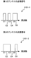
- FIG. 1 is a diagram showing a concept when a multi-antenna technique is applied to a spectrum clipping technique in the first embodiment of the present invention.
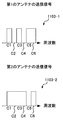
- the discrete frequencies (subcarriers) allocated to the mobile station apparatus are 6 points, and that C1, C2, C3, C4, C5, and C6 are from the lower frequencies, respectively.
- the mobile station apparatus transmits a frequency domain transmission signal 101-1 from the first transmission antenna and a frequency domain transmission signal 101-2 from the second transmission antenna.
- the same clipping is applied to each transmission antenna.
- the spectrum to which the signal is assigned is C1, C2, C3, C4, and C6, and C5 is clipped.
- positioned at each transmission antenna is the same thing.
- the received signal at the kth discrete frequency is expressed by the following equation (1).
- S (k) is a transmission signal represented by a complex number at the kth discrete frequency
- R (k) is a reception signal represented by a complex number at the kth discrete frequency
- H 1 (k) Is a propagation path characteristic represented by a complex number between the first antenna of the mobile station device and the antenna of the base station device
- H 2 (k) is the second antenna of the mobile station device from the antenna of the base station device.
- a propagation path characteristic represented by a complex number, ⁇ (k) is noise represented by a complex number including interference from adjacent cells.
- 1 / ⁇ 2 is a value for normalization so that the total transmission power from all transmission antennas is constant.
- the equivalent propagation path characteristic for the transmitted signal is H 1 (k) + H 2 (k). Therefore, clipping information and frequency allocation information are determined using this equivalent propagation path characteristic.
- the power gain G (k) of the transmission signal is expressed as Expression (2).
- Equation (2) the clipping information to be transmitted is determined.
- Equation (2) is calculated for all discrete frequencies included in the system band.
- the frequency allocation and the clipping ratio represented by Expression (2) are determined.
- proportional fairness (PF) commonly used when sharing the entire system band among a plurality of mobile station devices
- Max CIR Carrier-to-Interference-power Ratio, MaxSINR, Max-SNR
- RR round robin
- the clipping rate a method such as not assigning the assigned frequency when the value of the expression (2) is below a certain threshold value, a clipping rate defined in advance by the system, or a modulation method and encoding.
- a predefined clipping rate may be used. For example, in the case of QPSK with a coding rate of 1/2, it is assumed that the clipping rate is defined as 20%.
- a frequency position for clipping may be used.
- information related to transmission power allocation may be further notified, and this is the same in any embodiment disclosed in the present invention. .
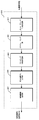
- FIG. 2 is a block diagram showing an example of a basic configuration of the mobile station apparatus according to the first embodiment of the present invention.
- the number of transmission / reception antennas of the mobile station apparatus is two.
- the number of transmitting and receiving antennas of the mobile station apparatus is not limited.
- the description will be made assuming that the number of spatially transmitted streams is 1.
- the mobile station apparatus receives control signals notified from the base station apparatus on the downlink by antennas 201-1 and 201-2 (the antennas 201-1 and 201-2 are collectively referred to as antenna 201), and wireless
- the receiving units 203-1 and 203-2 down-convert to baseband signals and perform A / D (Analog to Digital) conversion.
- the obtained digital signal is combined with a received signal such as maximum ratio combining by the combining unit 205.
- the control signal detector 207 detects information related to the reference signal sequence, information related to the clipping ratio, frequency allocation information, and the like from the combined received signal.
- the data signal generation unit 209 For the information bit string to be transmitted, the data signal generation unit 209 generates a frequency signal of the data to be transmitted.
- the data signal generation unit 209 performs error correction coding on the information bit sequence, generates modulation symbols such as QPSK (Quaternary Phase Shift Keying) and 16QAM (16-ary Quadrature Amplitude Modulation), and uses a frequency signal by DFT (Discrete Fourier Transform). Is converted to Next, a reference signal (RS: Reference Signal) for estimation of each transmission antenna propagation path is generated by the reference signal generation unit 211 based on information on the reference signal, and is multiplexed with the data signal by the reference signal multiplexing unit 213.
- the layer mapping unit 215 assigns a signal to each antenna 201.
- the number of spatially multiplexed signals (number of ranks) is 1, it is copied to each antenna 201 as it is, and if the number of ranks is 2, S / P (Serialelto Parallel) conversion or block is applied to each antenna 201.
- Different transmission signals are assigned using a method such as interleaving. In this embodiment, since it is assumed that the same signal is transmitted from the two antennas 201, it is assumed that the signals are transmitted in rank 1.
- the clipping information may be frequency position information for clipping or a clipping rate (for example, 10%).
- MCS Modulation and Coding Schemes
- the clipping rate may be notified in a one-to-one correspondence.
- the notified clipping information can be determined from the MCS.
- the frequency signal clipped by each antenna 201 is arranged at a frequency based on the frequency allocation information notified by the frequency allocation units 219-1 and 219-2.
- sounding reference signal multiplexing sections 221-1 and 221-2 multiplex sounding reference signals for grasping the propagation path characteristics from each antenna 201 to antenna 301, and IFFT (Inverse Fast Fourier Transform) unit 223-1. 223-2 is converted to a time domain signal.
- the transmission signal converted to the time domain is inserted with CPs at CP (Cyclic Prefix) insertion units 225-1 and 225-2, and is D / A (Digital to Analog) conversion with radio transmission units 227-1 and 227-2.
- CP Cyclic Prefix
- D / A Digital to Analog
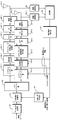
- FIG. 3 is a block diagram showing the configuration of the base station apparatus according to the first embodiment of the present invention.
- the reception signal received by the antenna 301 is received by the wireless reception unit 303, and the CP removal unit 305 removes the CP from the reception signal.
- the received signal is converted into a frequency signal by the FFT unit 307.
- the sounding reference signal separation unit 309 From the received signal converted into the frequency signal, the sounding reference signal separation unit 309 first separates the sounding reference signal.
- the separated sounding reference signal estimates the reception state (for example, reception SINR) from each antenna 201 to the antenna 301 in the channel sounding unit 311, and the estimated reception state and the estimated propagation path characteristic are the control unit 313. Is input.
- the control unit 313 determines clipping information and frequency allocation for each antenna 201.
- the determined control information is converted into a control signal by the control signal generation unit 315, subjected to D / A conversion and up-conversion by the wireless transmission unit 317, and transmitted from the antenna 301.
- the received signal from which the sounding reference signal is separated is removed from the received signal by the reference signal separation unit 319.
- a propagation path characteristic / noise power estimation unit 321 estimates a propagation path characteristic from each antenna 201 and noise power including interference from adjacent cells.
- the propagation path characteristic estimated by the propagation path characteristic / noise power estimation unit 321 calculates an equivalent propagation path by inserting zero into the frequency clipped by the zero insertion unit 323 on the mobile station apparatus side.
- the obtained equivalent propagation path is input to equalization section 325 and received signal replica generation section 327.
- the received signal output from the reference signal separating unit 319 cancels the received signal replica input from the received signal replica generating unit 327 in the signal canceling unit 329. However, nothing is canceled at the first repetition.
- the equalization unit 325 equalizes the received signal and extracts the desired signal from the frequency assigned by the frequency demapping unit 331 in the frequency domain.
- an IDFT (Inverse DiscreteIDFourier Transform) unit 333 converts the signal into a time signal, and a demodulator 335 obtains a log likelihood ratio (LLR: Log Likelihood Ratio).
- LLR Log Likelihood Ratio
- the LLR of the sign bit is input to the transmission signal replica generation unit 339, and a soft replica (soft estimation) of the transmission signal is generated. Thereafter, the signal is input to the DFT unit 341, and the soft estimation is converted into a frequency signal.
- the received signal replica is calculated by being converted into a frequency domain soft replica by the DFT unit 341 and multiplied by the equivalent propagation path output from the zero insertion unit 323 in the received signal replica generation unit 327. This is input to the signal cancel unit 329 and the above-described processing is repeated. This is repeated an arbitrary number of times, and the decoded bit string is obtained by making a hard decision on the LLR of the information bits output from the decoding unit 337.
- the control unit 313 will be described.
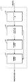
- FIG. 4 is a block diagram showing an example of the control unit 313 according to the first embodiment of the present invention.
- the frequency allocation is determined by the scheduling unit 401 according to the equation (2) from the estimated propagation path characteristics.
- the clipping information determination unit 403 generates clipping information for each antenna 201, and the frequency allocation determination unit 405 determines final frequency allocation.
- the control information generation unit 407 generates control information for the clipping information and frequency allocation obtained in this way, and inputs them to the control signal generation unit 315.
- the control signal generation unit 315 generates a control signal such as multiplexing / modulation by a method set according to the system and inputs the control signal to the wireless transmission unit 317.
- the clipping can be applied to the multi-antenna technique by determining the clipping information and the frequency allocation based on the combined equivalent propagation path when applied to the multi-antenna.
- FIG. 5 is a block diagram showing an example of a mobile station apparatus according to the second embodiment of the present invention.
- the layer mapping unit 215 is changed to a precoding unit 501.
- the precoding unit 501 multiplies a precoding matrix defined in advance.
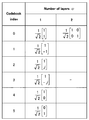
- FIG. 6 is a table showing a precoding matrix in LTE-A.
- a case where the number of transmission antennas is 2 is shown as an example.
- Number of layers ⁇ is the number of layers.
- the codebook index is an index used to notify the mobile station apparatus which matrix to use.
- rank 2 since rank 2 will be described in an embodiment to be described later, it will be described here using a rank 1 precoding matrix.
- the transmission signal of one stream is multiplied by the precoding matrix w shown in FIG. 6 and transmitted, the reception signal at the k-th frequency is expressed as in Expression (3).
- Equation (3) S (k) is the amplitude of the transmission signal represented by a complex number in the kth frequency domain, ⁇ (k) is noise including interference from adjacent cells, and R (k) is the received signal. Amplitude, w is any one matrix selected from the precoding matrix having one layer number shown in FIG. Moreover, h (k) is a propagation path matrix represented by 1 ⁇ 2, and is represented by Expression (4).
- h 1 (k) is a propagation path characteristic represented by a complex number of the kth frequency from the first antenna 201-1 to the antenna 301
- h 2 (k) is represented by a complex number of the kth frequency. This is a propagation path characteristic from the second antenna 201-2 to the antenna 301. Therefore, the power gain of the kth frequency expressed in this way is expressed as shown in Equation (5).
- Equation (5) P (k) represents a power gain for a transmission signal represented by a real number at the k-th frequency.
- the clipping frequency and frequency allocation are determined using the same method as in the first embodiment.
- the configuration of the receiving apparatus is the same as that in FIG. As described above, the present invention is also applicable when precoding is applied.
- the number of reception antennas has been described as one. However, when the number of reception antennas is two or more, reception is performed using reception diversity techniques such as maximum ratio combining (MRC: MaximumMaxRatio Combining).
- MRC MaximumMaxRatio Combining
- space-time coding STC: Space Time Coding, STBC (Space Time Block Code), SFBC (Space Frequency Block Code), etc.
- circulation Transmit diversity techniques such as delay diversity (CDD: Cyclic Delay Diversity), time switching transmission diversity (TSTD: Time Switching Switching Transmit Diversity), frequency switching transmission diversity (FSTD: Frequency Switching Diversity), antenna selection diversity, etc.
- CDD Cyclic Delay Diversity
- TSTD Time Switching Switching Transmit Diversity
- FSTD Frequency Switching Diversity
- a method of always transmitting from any one of the antennas 201 may be used.
- FIG. 7 is a block diagram showing an example of the control unit 313 according to the second embodiment of the present invention.
- the precoding matrix determination unit 601 selects an optimal precoding matrix based on the spatial correlation from each antenna 201 to antenna 301 output from the channel sounding unit 311 and the propagation path state of propagation path characteristics. Scheduling is performed in the scheduling unit 401 based on the selected precoding matrix.
- the present invention can be applied even when precoding is used.
- FIG. 8 is a diagram illustrating an example of the concept of the frequency signal of each antenna 201 in MIMO in the third embodiment of the present invention.
- the transmission signal 701-1 and the transmission signal 701-2 are different signals.
- FIG. 9 is a block diagram showing an example of a mobile station apparatus according to the third embodiment of the present invention.
- an S / P (Serial-to-Parallel) unit 801 performs serial-parallel conversion in order to transmit two streams.
- reference signal multiplexing sections 803-1 and 803-2 multiplex reference signals for demodulating each stream. Since the reference signal must be separable in the receiving device (base station device), a cyclic shift or a different code such as an orthogonal code is assigned to each.
- precoding section 501 multiplies rank 2 precoding matrix based on the notified precoding information.
- a matrix when ⁇ is 2 in FIG. 6, a unit matrix multiplied by 1 / ⁇ 2 is selected.
- other rank 2 matrices are defined in other mobile communication systems. If so, you can choose it.
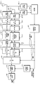
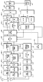
- FIG. 10 is a block diagram illustrating an example of a base station apparatus according to the third embodiment of the present invention.
- a configuration in which the number of antennas of the base station apparatus is 2, and a codeword number 1 and rank 2 signal is detected is shown as an example.
- Signals received by antennas 901-1 and 901-2 (antennas 901-1 and 901-2 are collectively referred to as antenna 901) are down-converted to baseband signals by radio reception units 903-1 and 903-2.
- CP is removed from the received signal by CP removing sections 905-1 and 905-2, converted into frequency signals by FFT sections 907-1 and 907-2, and sounding reference signal separating sections 909-1 and 909-2.
- the sounding reference signal is separated at.
- the channel sounding unit 911 estimates the state of the propagation path of the separated sounding reference signal.
- the estimated channel matrix can be expressed by a matrix as shown in Equation (6).
- h nm (k) is a propagation path matrix at the k-th discrete frequency between the m-th antenna 201 of the mobile station apparatus and the n-th antenna 901 of the base station apparatus.
- the index of each antenna 901 is configured as an element in the column direction of the matrix
- the index of each antenna 201 is configured as an element in the row direction of the matrix.
- This propagation path matrix is input to the control unit 913.
- FIG. 11 is a block diagram illustrating a configuration example of the control unit 913 according to the third embodiment of the present invention.
- the precoding matrix is determined by the precoding matrix determination unit 1001 and the propagation path characteristic input to the control unit 913 is input to the communication channel capacity calculation unit 1003.
- the communication channel capacity calculation unit 1003 calculates the communication channel capacity at each frequency (may be a resource block unit blocked by a plurality of discrete frequencies) as shown in Expression (7).
- u is an index of a resource block
- K is the number of discrete frequency points included in the resource block
- SINR is a received signal to interference noise power ratio
- det is a determinant.
- the channel capacity based on the strict definition is given as an example here, but even when a quantitative value having a correlation similar to the channel capacity is used, it is included in the present invention.
- the average channel capacity of each resource block is input to the scheduling unit 1005 and input to the clipping information determination unit 1007.
- the frequency allocation determination unit 1009 determines frequency allocation.
- the control information generation unit 1011 generates control information for the frequency allocation information and clipping information determined in this manner, and inputs the control information to the control signal generation unit 915.
- the control signal generation unit 915 generates a control signal corresponding to the system.
- the wireless transmission unit 917 converts the control signal into a wireless signal. Thereafter, the radio signal is transmitted from the antennas 901-1 and 901-2.
- the received signal from which the sounding reference signal is separated is separated into reference signals for each layer by reference signal separation sections 919-1 and 919-2, and each of the signals for each layer is separated by propagation path characteristic / noise power estimation section 921.
- the propagation path characteristics in the antenna 901 and the noise power in each antenna 901 are estimated.
- the obtained propagation path characteristic is inserted by the zero insertion unit 923 into the propagation path characteristic of the clipped frequency.
- the received signal from which the reference signal is separated is subtracted by the signal cancellation unit 925 from the received signal replica input from the received signal replica generation unit 927. However, nothing is canceled in the first process.
- the layer separation / equalization unit 929 uses the equivalent propagation path characteristics and noise power calculated by the zero insertion unit 923 to remove the layer separation and distortion caused by the propagation path from the received signal.
- An equalization process is performed.
- the received signals are returned by the frequency demapping units 931-1 and 931-2 in the order of the original discrete frequencies of the signals of each layer based on the assigned frequencies.
- the received signal is converted into a time signal by IDFT units 933-1 and 933-2, and restored by parallel / serial conversion of the received signal converted into the time domain by a P / S (Parallel to serial) unit 935. It is.
- the demodulation unit 937 calculates the LLR of the code bit, and the decoding unit 939 performs error correction.
- the LLR of the code bit obtained from the decoding unit 939 is calculated by the transmission signal replica generation unit 941 as a soft estimate (also referred to as a soft replica) of the transmission signal, and is again converted into a signal for each layer by the S / P unit 943. Serial-parallel conversion is performed.
- the DFT units 945-1 and 945-2 generate soft estimation values (soft replicas) in the frequency domain, and the received signal replica generation unit 927 determines the equivalent propagation path characteristics output from the zero insertion unit 923.
- the received signal replica is generated by multiplication.
- the obtained received signal replica is input again to the signal cancel unit 925.
- the above processing is repeated an arbitrary number of times (predetermined number of times until there is no error), and finally, a decoded bit is obtained by hard-deciding the LLR of the information bit output from the decoding unit 939.
- clipping technology can be applied to MIMO technology.
- the essence of the present invention is the processing of the control unit 913 shown in FIG. 11 and determines clipping information from the channel capacity.
- the first to third embodiments can be selected adaptively in combination by adaptive control such as rank adaptation, and these combinations are also included in the present invention.
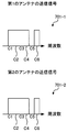
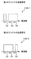
- FIG. 12A is a diagram illustrating a case where signals from the respective antennas 201 are independently set in the fourth embodiment of the present invention.
- the transmission signals 1101-1 and 1101-2 are each independently clipped.
- the same signal is transmitted at frequencies C1, C3, and C6, and the frequency C4 is clipped by both antennas 201.
- the frequencies C2 and C5 are transmitted from one antenna 201.
- FIG. 12B is a diagram showing a case where a signal from at least one antenna 201 is assigned at any frequency in the fourth embodiment of the present invention. Unlike FIG. 12A, as shown in the transmission signal 1103-2, the transmission signal is also arranged in C4. Thereby, since there is no missing information in the antenna 301, the detection accuracy can be improved.
- FIG. 12C is a diagram illustrating a case where the clipping ratio is limited and control is performed so that a signal is allocated to at least one frequency in the fourth embodiment of the present invention.
- the clipping rate is limited, and different clipping is performed for each antenna 201 so as to realize the assignment of a signal to at least one frequency.
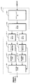
- FIG. 13 is a block diagram showing an example of the configuration of the control unit 313 according to the fourth embodiment of the present invention.
- rank 1 transmission is taken as an example.
- clipping differs for each antenna 201
- the configuration of the base station apparatus may be the same as that shown in FIG. However, the configuration of the control unit 313 is different. In FIG.
- control unit 313 uses the scheduling unit 1201 to determine the allocated frequency position in the system band, and the gain calculation unit 1203 calculates the channel gain from each antenna 201 at the determined frequency position.
- Gain calculation section 1203 calculates the gain of the propagation path as shown in equation (8).
- F 1 (k) and F 2 (k) are the gain at the kth frequency from antenna 201-1 to antenna 301 and the gain at the kth frequency from antenna 201-2 to antenna 301, respectively.
- h 1 (k) and h 2 (k) respectively represent the propagation path characteristics at the k th frequency from antenna 201-1 to antenna 301, and the propagation path characteristics at the k th frequency from antenna 201-2 to antenna 301.
- clipping information determination sections 1205-1 and 1205-2 determine clipping information, respectively
- frequency allocation determination sections 1207-1 and 1207-2 determine allocation frequencies.
- the frequency assignment determination units 1207-1 and 1207-2 represent frequencies to which the signal after clipping is assigned.
- the frequency allocation information and clipping information are input to the control information generation unit 1209, whereby the control information generation unit 1209 generates control information and inputs the control information to the control signal generation unit 315.
- the present invention is characterized in that different clipping is performed for each of a plurality of transmission antennas or for each of a plurality of layers (spatial multiplexing). If there are a plurality of receiving antennas, the value of equation (9) is taken as the gain.
- h nm (k) represents the propagation path characteristic from the antenna (layer) 201-m to the antenna 301-n.
- the gain is expressed as a sum obtained by adding the square of the absolute value by the number of reception antennas.
- the configuration example of the mobile station apparatus is the same as that in FIG. 5, and the frequency positions to be clipped by the spectrum clipping units 217-1 and 217-2 are different from each other.
- the number of the clipping information determination units 1205-1 and 1205-2 is provided for the number of the antennas 201, and the transmission characteristics are improved by determining the clipping information independently.
- the present invention essentially determines the clipping information for each antenna 201, the scope of the invention is not limited by the number of receiving antennas.
- a frequency with a low gain may be set, or a method of selecting one from predefined methods may be used.
- F T (k) represents the gain estimated at the k-th frequency between the T-th antenna 201 and the base station apparatus.
- ⁇ represents a real number that can be arbitrarily set.
- ⁇ is larger than 1, and when it is virtually calculated that no antenna 201 is clipped, ⁇ Is 1.
- the frequency for clipping again considering this P T (k) as a virtual propagation path is set. decide. Furthermore, by controlling ⁇ , it is possible to control the number of transmit antennas that can be clipped at the same frequency. For example, it sets like Formula (11). ⁇ may be set for each discrete frequency (subcarrier), or may be the same value for all subcarriers.
- n t is the number of transmission antennas that are clipped at the k-th frequency. It is also possible to set in this way. Such a method is also considered as an example. Furthermore, although it has been described that the frequency is not determined to be virtually clipped when ⁇ is 1, it is not necessary to be 1 if the method realizes the same concept.
- FIG. 14 is a block diagram showing an example of the configuration of the control unit 313 according to the fourth embodiment of the present invention.
- the gain of each antenna 201 output from the gain calculation unit 1203 is multiplied by ⁇ in the gain correction units 1301-1 and 1301-2 when clipping is expected in any one of the antennas 201, and clipping is performed. If it is determined that it will not be performed, a process of doing nothing is performed. Thereby, it is possible to realize the assignment as shown in FIG. 12B.
- the clipping rate is set based on the amount of inter-symbol interference (ISI) caused by clipping, EXT (Extrinsic Information Transfer) analysis, mutual information amount, and the like.
- ISI inter-symbol interference
- EXT Extransic Information Transfer
- Various methods may be used, such as limiting.
- the essence of the present invention is a method for setting a clipping frequency to be different between antennas 201 or between layers when spatially multiplexing a plurality of signals, and all means for realizing such a method are included in the present invention.
- the number of transmitting and receiving antennas is not limited. These may be applied to multicarrier transmission such as OFDM.
- the first to fourth embodiments have shown the modes performed by the control unit of the base station apparatus, but of course, since this is also possible with the mobile station apparatus, such a case is also included in the present invention.
- the clipping rate in this embodiment, the clipping rate is the most suitable control.
- any notification method can be used regardless of the method for determining the frequency allocation and the frequency for clipping, such as the frequency position for clipping. You may notify by.
- the program that operates in the mobile station apparatus and the base station apparatus related to the present invention is a program (a program that causes a computer to function) that controls the CPU and the like so as to realize the functions of the above-described embodiments related to the present invention.
- Information handled by these devices is temporarily stored in the RAM at the time of processing, then stored in various ROMs and HDDs, read out by the CPU, and corrected and written as necessary.
- a recording medium for storing the program a semiconductor medium (for example, ROM, nonvolatile memory card, etc.), an optical recording medium (for example, DVD, MO, MD, CD, BD, etc.), a magnetic recording medium (for example, magnetic tape, Any of a flexible disk etc. may be sufficient.
- the processing is performed in cooperation with the operating system or other application programs.
- the functions of the invention may be realized.
- the program when distributing to the market, can be stored and distributed on a portable recording medium, or transferred to a server computer connected via a network such as the Internet.
- the storage device of the server computer is also included in the present invention.
- LSI is typically an integrated circuit.
- Each functional block of the mobile station apparatus and the base station apparatus may be individually chipped, or a part or all of them may be integrated into a chip.
- the method of circuit integration is not limited to LSI, and may be realized by a dedicated circuit or a general-purpose processor.
Abstract
The present invention provides a wireless controller which improves frequency utilization efficiency by clipping signals transmitted from a mobile station device in the case where the mobile station device uses multiple antennas. The wireless controller performs clipping processing that does not transmit the spectrum of part of a frequency range, and the wireless controller is suitable for use in a wireless communication system for transmitting and receiving data. Based on propagation path information with a wireless terminal constituting a communication partner, the wireless controller determines frequency allocation for the wireless terminal and generates frequency allocation information while also generating clipping information indicating a frequency range for performing the clipping processing, and the wireless controller transmits the frequency allocation information and the clipping information to the wireless terminal.
Description
本発明は、マルチアンテナ使用時のスペクトルクリッピング方法に関する。
The present invention relates to a spectrum clipping method when a multi-antenna is used.
第3.9世代の携帯電話の無線通信システムであるLTE(Long Term Evolution)システムの標準化がほぼ完了し、最近ではLTEシステムをより発展させたLTE-A(LTE-Advanced)が、第4世代の無線通信システム(IMT-Aなどとも称する。)の候補の一つとして標準化が行なわれている。一般的に、移動通信システムの上り回線(移動局から基地局への通信)では、移動局が送信局となるため、限られた送信電力で増幅器の電力利用効率を高く維持でき、ピーク電力の低いシングルキャリア方式(LTEではSC-FDMA(Single Carrier Frequency Division Multiple Access)方式が採用されている)が有効とされている。なお、SC-FDMAはDFT-S-OFDM(Discrete Fourier Transform Spread Orthogonal Frequency Division Multiplexing)やDFT-precoded OFDMなどとも呼ばれる。
Standardization of the LTE (Long Term Evolution) system, which is the wireless communication system for the 3.9th generation mobile phone, is almost completed. Recently, LTE-A (LTE-Advanced), which is a further development of the LTE system, is the fourth generation. Standardization is being carried out as one of the candidates for wireless communication systems (also referred to as IMT-A, etc.). Generally, in the uplink of a mobile communication system (communication from a mobile station to a base station), the mobile station becomes a transmitting station, so that the power utilization efficiency of the amplifier can be maintained high with limited transmission power, and the peak power A low single carrier system (LTE adopts SC-FDMA (Single-Carrier-Frequency-Division-Multiple-Access) system) is effective. Note that SC-FDMA is also called DFT-S-OFDM (Discrete-Fourier-Transform-Spread-Orthogonal-Frequency-Division-Multiplexing) and DFT-precoded OFDM.
LTE-Aでは、さらに周波数利用効率を改善させるために、送信電力に余裕のある端末については、SC-FDMAスペクトルを複数のサブキャリアから構成されるクラスタに分割し、各クラスタを周波数軸の任意の周波数に配置するClustered DFT-S-OFDM(ダイナミックスペクトル制御(DSC:Dynamic Spectrum Control)、SC-ASA(Single Carrier Adaptive Spectrum Allocation)などとも称される。)と呼ばれるアクセス方式を新たにサポートすることが決定されている。さらに、受信処理においてターボ等化を行なうことを前提に、各移動局装置からの周波数信号に対してクリッピングを含むスペクトル整形を施すことで、周波数利用効率を改善させる手法が提案されている(例えば、非特許文献1)。
In LTE-A, in order to further improve the frequency utilization efficiency, for terminals with sufficient transmission power, the SC-FDMA spectrum is divided into clusters composed of a plurality of subcarriers, and each cluster is arbitrarily assigned on the frequency axis. To support a new access method called Clustered DFT-S-OFDM (also called Dynamic Spectrum Control (DSC), SC-ASA (Single Carrier Adaptive Adaptive Spectrum) Allocation)) Has been determined. Furthermore, on the premise that turbo equalization is performed in the reception process, a technique for improving frequency utilization efficiency by applying spectrum shaping including clipping to a frequency signal from each mobile station apparatus has been proposed (for example, Non-Patent Document 1).
図15は、非特許文献1で開示されたスペクトルクリッピングの概念を示す図である。元のシングルキャリアスペクトル1に対して、一部の周波数信号をクリッピング(削除)し、送信信号3を生成する。このとき、クリッピングされる周波数信号は伝搬路特性に応じて施す。これを受信した受信信号5は、当然、送信側でクリップした周波数信号は欠落したまま受信される。その後、信号がクリッピングされた周波数の伝搬路利得がゼロであると見做してターボ等化で検出すると、推定信号7のように周波数信号を再生することができる。
FIG. 15 is a diagram showing the concept of spectrum clipping disclosed in Non-Patent Document 1. A part of the frequency signal is clipped (deleted) from the original single carrier spectrum 1 to generate a transmission signal 3. At this time, the frequency signal to be clipped is applied according to the propagation path characteristics. Of course, the received signal 5 received is received with the frequency signal clipped on the transmission side missing. Thereafter, assuming that the propagation path gain of the frequency at which the signal is clipped is zero and detecting by turbo equalization, the frequency signal can be reproduced like the estimated signal 7.
しかしながら、送受信アンテナを複数具備するマルチアンテナ技術(MIMO(Multiple-Input Multiple-Output)技術など)にクリッピングを適用する方法は開示されていない。よって、マルチアンテナ使用時においては、移動局装置からの送信信号に対してクリッピングを含むスペクトル整形を施すことによる周波数利用効率改善を行なうことができなかった。
However, a method for applying clipping to a multi-antenna technology (such as MIMO (Multiple-Input-Multiple-Output) technology) having a plurality of transmission / reception antennas is not disclosed. Therefore, when the multi-antenna is used, the frequency utilization efficiency cannot be improved by applying spectrum shaping including clipping to the transmission signal from the mobile station apparatus.
本発明は、このような事情に鑑みてなされたものであり、移動局装置がマルチアンテナを使用する場合において、移動局装置からの送信信号に対するクリッピングにより、周波数利用効率改善を行なうことができる無線制御装置、無線端末装置、無線通信システム、無線制御装置および無線端末装置の制御プログラムおよび集積回路を提供することを目的とする。
The present invention has been made in view of such circumstances, and in the case where a mobile station apparatus uses a multi-antenna, a radio that can improve frequency utilization efficiency by clipping a transmission signal from the mobile station apparatus. It is an object to provide a control device, a wireless terminal device, a wireless communication system, a wireless control device, a control program for the wireless terminal device, and an integrated circuit.
(1)上記の目的を達成するために、本発明は、以下のような手段を講じた。すなわち、本発明の無線制御装置は、周波数領域の一部のスペクトルを送信しないクリッピング処理を行なってデータを送受信する無線通信システムに適用される無線制御装置であって、通信相手である無線端末装置との間の伝搬路情報に基づいて、前記クリッピング処理を行なう周波数領域を示すクリッピング情報を生成すると共に、前記無線端末装置に対する周波数割り当てを決定して周波数割り当て情報を生成し、前記クリッピング情報および前記周波数割り当て情報を前記無線端末装置に対して通知することを特徴としている。
(1) In order to achieve the above object, the present invention has taken the following measures. That is, the radio control apparatus of the present invention is a radio control apparatus applied to a radio communication system that transmits and receives data by performing clipping processing that does not transmit a part of the spectrum in the frequency domain, and is a radio terminal apparatus that is a communication counterpart Based on the propagation path information between and generating the clipping information indicating the frequency region where the clipping processing is performed, and determining the frequency allocation for the wireless terminal device to generate the frequency allocation information, the clipping information and the The frequency allocation information is notified to the wireless terminal device.
このように、無線制御装置は、クリッピング処理を行なう周波数領域を示すクリッピング情報を生成すると共に、無線端末装置に対する周波数割り当てを決定して周波数割り当て情報を生成し、クリッピング情報および周波数割り当て情報を無線端末装置に対して通知するので、無線端末装置がマルチアンテナを使用する場合において、無線端末装置からの送信信号に対するクリッピングが可能となり、周波数利用効率改善を行なうことができる。
As described above, the radio control apparatus generates clipping information indicating a frequency region in which clipping processing is performed, determines frequency allocation for the radio terminal apparatus, generates frequency allocation information, and transmits the clipping information and frequency allocation information to the radio terminal. Since the notification is made to the apparatus, when the wireless terminal apparatus uses a multi-antenna, clipping can be performed on the transmission signal from the wireless terminal apparatus, and the frequency utilization efficiency can be improved.
(2)また、本発明の無線制御装置において、前記無線端末装置が複数の送信アンテナを備える場合、前記各送信アンテナにおけるクリッピング情報をそれぞれ独立に決定することを特徴としている。
(2) Further, in the wireless control device of the present invention, when the wireless terminal device includes a plurality of transmitting antennas, the clipping information in each transmitting antenna is determined independently.
このように、無線制御装置は、各送信アンテナにおけるクリッピング情報をそれぞれ独立に決定するので、送信アンテナ毎に共通に決定する方法に比べ、欠落する情報をなくすことができ、検出精度を高めることが可能である。これにより高い伝送特性を得ることができる。
As described above, since the radio network controller determines the clipping information for each transmission antenna independently, it is possible to eliminate the missing information and improve the detection accuracy compared to the method for determining each transmission antenna in common. Is possible. Thereby, high transmission characteristics can be obtained.
(3)また、本発明の無線制御装置において、前記クリッピング情報は、クリッピング処理をする周波数領域とクリッピング処理をしない周波数領域との割合を示すクリッピング率を示す情報、またはクリッピング処理を行なう周波数位置を示す情報の少なくとも一方を含むことを特徴としている。
(3) In the radio control apparatus of the present invention, the clipping information includes information indicating a clipping ratio indicating a ratio between a frequency region where clipping processing is performed and a frequency region where clipping processing is not performed, or a frequency position where clipping processing is performed. It contains at least one of the information to show.
このように、クリッピング情報が、クリッピング処理をする周波数領域とクリッピング処理をしない周波数領域との割合を示すクリッピング率を示す情報、またはクリッピング処理を行なう周波数位置を示す情報の少なくとも一方を含むので、無線制御装置は、柔軟に制御することが可能となる。
As described above, since the clipping information includes at least one of information indicating a clipping ratio indicating a ratio between a frequency region where clipping processing is performed and a frequency region where clipping processing is not performed, or information indicating a frequency position where clipping processing is performed. The control device can be controlled flexibly.
(4)また、本発明の無線制御装置において、前記各送信アンテナにおけるクリッピング情報は、前記各アンテナに対応する伝搬路のゲインに基づいて決定されることを特徴としている。
(4) Further, in the radio control device of the present invention, the clipping information in each transmission antenna is determined based on a gain of a propagation path corresponding to each antenna.
このように、各送信アンテナにおけるクリッピング情報は、各アンテナに対応する伝搬路のゲインに基づいて決定されるので、無線制御装置は、送信ダイバーシチゲイン(あるいはビームフォーミングゲイン)や通信路容量から決定する方法に比べ、欠落する情報をなくすことができ、検出精度を高めることが可能である。これにより高い伝送特性を得ることができる。
As described above, since the clipping information in each transmission antenna is determined based on the gain of the propagation path corresponding to each antenna, the radio control apparatus determines from the transmission diversity gain (or beamforming gain) and the channel capacity. Compared with the method, missing information can be eliminated and detection accuracy can be improved. Thereby, high transmission characteristics can be obtained.
(5)また、本発明の無線制御装置において、前記各送信アンテナにおける伝搬路のゲインは、他の送信アンテナで送信される周波数領域の信号について、前記クリッピング処理が行なわれるか否かの判断結果に基づいて補正されることを特徴としている。
(5) Further, in the radio network controller of the present invention, the gain of the propagation path in each transmission antenna is a result of determining whether or not the clipping process is performed on a frequency domain signal transmitted from another transmission antenna. It is characterized by being corrected based on the above.
このように、各送信アンテナにおける伝搬路のゲインは、他の送信アンテナで送信される周波数領域の信号について、クリッピング処理が行なわれるか否かの判断結果に基づいて補正されるので、無線制御装置は、欠落する情報をなくすことができ、検出精度を高めることが可能である。これにより高い伝送特性を得ることができる。
Thus, since the gain of the propagation path in each transmission antenna is corrected based on the determination result of whether or not clipping processing is performed on the signal in the frequency domain transmitted by the other transmission antenna, the radio control apparatus Can eliminate missing information and improve detection accuracy. Thereby, high transmission characteristics can be obtained.
(6)また、本発明の無線制御装置において、前記無線端末装置が複数の送信アンテナを備える場合、前記各送信アンテナにおける共通のクリッピング情報を決定することを特徴としている。
(6) Further, in the wireless control device of the present invention, when the wireless terminal device includes a plurality of transmission antennas, the common clipping information in each of the transmission antennas is determined.
このように、無線制御装置は、無線端末装置が複数の送信アンテナを備える場合、各送信アンテナにおける共通のクリッピング情報を決定するので、無線端末装置がマルチアンテナを使用する場合において、無線端末装置からの送信信号に対するクリッピングが可能となり、周波数利用効率改善を行なうことができる。
Thus, when the wireless terminal device includes a plurality of transmission antennas, the wireless control device determines common clipping information in each transmission antenna. Therefore, when the wireless terminal device uses multiple antennas, Therefore, it is possible to improve the frequency utilization efficiency.
(7)また、本発明の無線制御装置において、前記クリッピング情報は、クリッピング処理をする周波数領域とクリッピング処理をしない周波数領域との割合を示すクリッピング率を示す情報、またはクリッピング処理を行なう周波数位置を示す情報の少なくとも一方を含むことを特徴としている。
(7) In the radio control device of the present invention, the clipping information includes information indicating a clipping ratio indicating a ratio between a frequency region where clipping processing is performed and a frequency region where clipping processing is not performed, or a frequency position where clipping processing is performed. It contains at least one of the information to show.
このように、クリッピング情報が、クリッピング処理をする周波数領域とクリッピング処理をしない周波数領域との割合を示すクリッピング率を示す情報、またはクリッピング処理を行なう周波数位置を示す情報の少なくとも一方を含むので、無線制御装置は、柔軟に制御することが可能となる。
As described above, since the clipping information includes at least one of information indicating a clipping ratio indicating a ratio between a frequency region where clipping processing is performed and a frequency region where clipping processing is not performed, or information indicating a frequency position where clipping processing is performed. The control device can be controlled flexibly.
(8)また、本発明の無線制御装置において、前記クリッピング情報は、前記無線端末装置の通信路容量に基づいて決定されることを特徴としている。
(8) In the wireless control device of the present invention, the clipping information is determined based on a communication channel capacity of the wireless terminal device.
このように、クリッピング情報が、無線端末装置の通信路容量に基づいて決定されるので、無線制御装置は、無線端末装置がマルチアンテナを使用する場合において、無線端末装置からの送信信号に対するクリッピングが可能となり、周波数利用効率改善を行なうことができる。
As described above, since the clipping information is determined based on the channel capacity of the wireless terminal device, the wireless control device performs clipping on the transmission signal from the wireless terminal device when the wireless terminal device uses a multi-antenna. This makes it possible to improve frequency utilization efficiency.
(9)また、本発明の無線端末装置は、周波数領域の一部のスペクトルを送信しないクリッピング処理を行なってデータを送受信する無線通信システムに適用される無線端末装置であって、通信相手である無線制御装置から、クリッピング処理を行なう周波数領域を示すクリッピング情報および周波数割り当てを示す周波数割り当て情報を受信し、前記受信したクリッピング情報および周波数割り当て情報に基づいて、周波数領域に対してクリッピング処理を行ない、前記クリッピング処理を行なった周波数信号を時間領域の信号に変換して、前記無線制御装置に対して送信することを特徴としている。
(9) Moreover, the wireless terminal device of the present invention is a wireless terminal device applied to a wireless communication system that transmits and receives data by performing clipping processing that does not transmit a part of the spectrum in the frequency domain, and is a communication partner. From the radio control device, receiving the clipping information indicating the frequency region for performing the clipping processing and the frequency allocation information indicating the frequency allocation, and performing the clipping processing on the frequency region based on the received clipping information and frequency allocation information, The frequency signal subjected to the clipping process is converted into a time domain signal and transmitted to the radio control apparatus.
このように、無線端末装置が、受信したクリッピング情報および周波数割り当て情報に基づいて、周波数領域に対してクリッピング処理を行なうので、無線制御装置は、無線端末装置がマルチアンテナを使用する場合において、無線端末装置からの送信信号に対するクリッピングが可能となり、周波数利用効率改善を行なうことができる。
As described above, since the wireless terminal device performs clipping processing on the frequency domain based on the received clipping information and frequency allocation information, the wireless control device performs wireless communication when the wireless terminal device uses a multi-antenna. Clipping can be performed on a transmission signal from the terminal device, and frequency use efficiency can be improved.
(10)また、本発明の無線通信システムは、上記(1)から(8)のいずれかに記載の無線制御装置と、上記(9)記載の無線端末装置と、から構成されることを特徴としている。
(10) Moreover, the wireless communication system of the present invention includes the wireless control device according to any one of (1) to (8) above and the wireless terminal device according to (9) above. It is said.
このように、無線通信システムが、上記(1)から(8)のいずれかに記載の無線制御装置と、上記(9)記載の無線端末装置と、から構成されるので、無線端末装置がマルチアンテナを使用する場合において、無線端末装置からの送信信号に対するクリッピングが可能となり、周波数利用効率改善を行なうことができる。
As described above, the wireless communication system includes the wireless control device according to any one of (1) to (8) above and the wireless terminal device according to (9) above. In the case of using an antenna, it is possible to clip a transmission signal from a wireless terminal device, and it is possible to improve frequency utilization efficiency.
(11)また、本発明の無線制御装置の制御プログラムは、周波数領域の一部のスペクトルを送信しないクリッピング処理を行なってデータを送受信する無線通信システムに適用される無線制御装置の制御プログラムであって、通信相手である無線端末装置との間の伝搬路情報に基づいて、前記クリッピング処理を行なう周波数領域を示すクリッピング情報を生成する処理と、前記無線端末装置に対する周波数割り当てを決定して周波数割り当て情報を生成する処理と、前記クリッピング情報および前記周波数割り当て情報を前記無線端末装置に対して通知する処理と、の一連の処理を、コンピュータに実行させることを特徴としている。
(11) Further, the control program of the wireless control device of the present invention is a control program for a wireless control device applied to a wireless communication system that transmits and receives data by performing clipping processing that does not transmit a part of the spectrum in the frequency domain. Then, based on propagation path information with the wireless terminal device that is the communication partner, processing for generating clipping information indicating a frequency region for performing the clipping processing, and frequency allocation for the wireless terminal device are determined and frequency allocation is performed. The computer is caused to execute a series of processes including a process of generating information and a process of notifying the wireless terminal device of the clipping information and the frequency allocation information.
このように、無線制御装置は、クリッピング情報および周波数割り当て情報を無線端末装置に対して通知するので、無線端末装置がマルチアンテナを使用する場合において、無線端末装置からの送信信号に対するクリッピングが可能となり、周波数利用効率改善を行なうことができる。
As described above, since the radio control apparatus notifies the radio terminal apparatus of the clipping information and the frequency allocation information, when the radio terminal apparatus uses a multi-antenna, clipping can be performed on a transmission signal from the radio terminal apparatus. The frequency utilization efficiency can be improved.
(12)また、本発明の無線端末装置の制御プログラムは、周波数領域の一部のスペクトルを送信しないクリッピング処理を行なってデータを送受信する無線通信システムに適用される無線端末装置の制御プログラムであって、通信相手である無線制御装置から、クリッピング処理を行なう周波数領域を示すクリッピング情報および周波数割り当てを示す周波数割り当て情報を受信する処理と、前記受信したクリッピング情報および周波数割り当て情報に基づいて、周波数領域に対してクリッピング処理を行なう処理と、前記クリッピング処理を行なった周波数信号を時間領域の信号に変換して、前記無線制御装置に対して送信する処理と、の一連の処理を、コンピュータに実行させることを特徴としている。
(12) A control program for a wireless terminal device according to the present invention is a control program for a wireless terminal device applied to a wireless communication system that transmits and receives data by performing clipping processing that does not transmit a part of the spectrum in the frequency domain. Based on the received clipping information and frequency allocation information, a process for receiving clipping information indicating a frequency domain for performing clipping processing and frequency allocation information indicating a frequency allocation from a radio control apparatus that is a communication partner, A computer executes a series of processes including a process for performing clipping processing on a signal, a process for converting the frequency signal subjected to the clipping process into a signal in a time domain, and transmitting the signal to the radio control apparatus. It is characterized by that.
このように、無線端末装置が、受信したクリッピング情報および周波数割り当て情報に基づいて、周波数領域に対してクリッピング処理を行なうので、無線制御装置は、無線端末装置がマルチアンテナを使用する場合において、無線端末装置からの送信信号に対するクリッピングが可能となり、周波数利用効率改善を行なうことができる。
As described above, since the wireless terminal device performs clipping processing on the frequency domain based on the received clipping information and frequency allocation information, the wireless control device performs wireless communication when the wireless terminal device uses a multi-antenna. Clipping can be performed on a transmission signal from the terminal device, and frequency use efficiency can be improved.
(13)また、本発明の集積回路は、無線制御装置に実装されることにより、前記無線制御装置に複数の機能を発揮させる集積回路であって、通信相手である無線端末装置との間の伝搬路情報に基づいて、前記クリッピング処理を行なう周波数領域を示すクリッピング情報を生成する機能と、前記無線端末装置に対する周波数割り当てを決定して周波数割り当て情報を生成する機能と、前記クリッピング情報および前記周波数割り当て情報を前記無線端末装置に対して通知する機能と、の一連の機能を、前記無線制御装置に発揮させることを特徴としている。
(13) An integrated circuit according to the present invention is an integrated circuit that is mounted on a wireless control device to cause the wireless control device to perform a plurality of functions, and is connected to a wireless terminal device that is a communication partner. A function of generating clipping information indicating a frequency region in which the clipping process is performed based on propagation path information; a function of determining frequency allocation for the wireless terminal device to generate frequency allocation information; the clipping information and the frequency The wireless control device is caused to exhibit a series of functions including a function of notifying the wireless terminal device of allocation information.
このように、無線制御装置は、クリッピング情報および周波数割り当て情報を無線端末装置に対して通知するので、第1の通信装置がマルチアンテナを使用する場合において、第1の通信装置からの送信信号に対するクリッピングが可能となり、周波数利用効率改善を行なうことができる。
As described above, since the radio control apparatus notifies the radio terminal apparatus of the clipping information and the frequency allocation information, when the first communication apparatus uses a multi-antenna, the radio control apparatus responds to the transmission signal from the first communication apparatus. Clipping becomes possible, and frequency use efficiency can be improved.
(14)また、本発明の集積回路は、無線端末装置に実装されることにより、前記無線端末装置に複数の機能を発揮させる集積回路であって、通信相手である無線制御装置から、クリッピング処理を行なう周波数領域を示すクリッピング情報および周波数割り当てを示す周波数割り当て情報を受信する機能と、前記受信したクリッピング情報および周波数割り当て情報に基づいて、周波数領域に対してクリッピング処理を行なう機能と、前記クリッピング処理を行なった周波数信号を時間領域の信号に変換して、前記無線制御装置に対して送信する機能と、の一連の機能を、前記無線端末装置に発揮させることを特徴としている。
(14) An integrated circuit according to the present invention is an integrated circuit that is mounted on a wireless terminal device to cause the wireless terminal device to perform a plurality of functions, and performs clipping processing from a wireless control device that is a communication partner. A function of receiving the clipping information indicating the frequency domain to be performed and the frequency allocation information indicating the frequency allocation, a function of performing a clipping process on the frequency domain based on the received clipping information and the frequency allocation information, and the clipping process The radio terminal apparatus is caused to exhibit a series of functions of converting the frequency signal subjected to the above to a signal in the time domain and transmitting the signal to the radio network controller.
このように、受信したクリッピング情報および周波数割り当て情報に基づいて、周波数領域に対してクリッピング処理を行なうので、無線制御装置は、無線端末装置がマルチアンテナを使用する場合において、無線端末装置からの送信信号に対するクリッピングが可能となり、周波数利用効率改善を行なうことができる。
As described above, since the clipping process is performed on the frequency domain based on the received clipping information and frequency allocation information, the radio control apparatus transmits data from the radio terminal apparatus when the radio terminal apparatus uses multiple antennas. Clipping on a signal becomes possible, and frequency utilization efficiency can be improved.
本発明により、マルチアンテナ技術にスペクトル整形を適用することができる。これにより、基地局装置は、移動局装置がマルチアンテナを使用する場合において、移動局装置からの送信信号に対するクリッピングにより、周波数利用効率改善を行なうことができる。
According to the present invention, spectrum shaping can be applied to multi-antenna technology. Thereby, the base station apparatus can improve the frequency utilization efficiency by clipping the transmission signal from the mobile station apparatus when the mobile station apparatus uses a multi-antenna.
以下、本発明の実施形態について図面を参照して説明する。なお、以下の実施形態では、スペクトル整形に含まれるクリッピング処理を対象にしており、送信される周波数信号(クリッピングされていない周波数信号)への電力配分に関しては特に記載しないが、電力配分を行なう処理を含むスペクトル整形をした場合も本発明に含まれる。
Hereinafter, embodiments of the present invention will be described with reference to the drawings. In the following embodiments, clipping processing included in spectrum shaping is targeted, and power distribution to a frequency signal to be transmitted (frequency signal that is not clipped) is not particularly described, but power distribution processing is performed. The present invention also includes the case of spectrum shaping including
[第1の実施形態](2x1送信ダイバーシチ)
本実施形態は、クリッピングする周波数を送信に使用する送信アンテナ毎に共通に決定する方法について述べる。 [First Embodiment] (2 × 1 transmission diversity)
In the present embodiment, a method for commonly determining a clipping frequency for each transmission antenna used for transmission will be described.
本実施形態は、クリッピングする周波数を送信に使用する送信アンテナ毎に共通に決定する方法について述べる。 [First Embodiment] (2 × 1 transmission diversity)
In the present embodiment, a method for commonly determining a clipping frequency for each transmission antenna used for transmission will be described.
図1は、本発明の第1の実施形態において、マルチアンテナ技術をスペクトルクリッピング技術に適用する場合の概念を示す図である。図1では、移動局装置に割り当てられた離散周波数(サブキャリア)が6ポイントであり、それぞれ、低い周波数からC1、C2、C3、C4、C5、C6であるものとする。移動局装置は、第1の送信アンテナから周波数領域の送信信号101-1、第2の送信アンテナから周波数領域の送信信号101-2を送信する。ここでは、同図に示されるように、各送信アンテナで同一のクリッピングを施すものとする。ここでは、信号が割り当てられたスペクトルがC1、C2、C3、C4、C6であり、C5はクリッピングされている。また、各送信アンテナに配置された信号は同一のものである。送信に使用するアンテナ数を2、基地局装置で受信に使用するアンテナ数を1とすると、k番目の離散周波数における受信信号は、次式(1)で表される。

FIG. 1 is a diagram showing a concept when a multi-antenna technique is applied to a spectrum clipping technique in the first embodiment of the present invention. In FIG. 1, it is assumed that the discrete frequencies (subcarriers) allocated to the mobile station apparatus are 6 points, and that C1, C2, C3, C4, C5, and C6 are from the lower frequencies, respectively. The mobile station apparatus transmits a frequency domain transmission signal 101-1 from the first transmission antenna and a frequency domain transmission signal 101-2 from the second transmission antenna. Here, as shown in the figure, the same clipping is applied to each transmission antenna. Here, the spectrum to which the signal is assigned is C1, C2, C3, C4, and C6, and C5 is clipped. Moreover, the signal arrange | positioned at each transmission antenna is the same thing. When the number of antennas used for transmission is 2 and the number of antennas used for reception at the base station apparatus is 1, the received signal at the kth discrete frequency is expressed by the following equation (1).
式(1)において、S(k)は、k番目の離散周波数における複素数で表される送信信号、R(k)はk番目の離散周波数における複素数で表される受信信号、H1(k)は、移動局装置の第1のアンテナから基地局装置のアンテナの間の複素数で表される伝搬路特性、H2(k)は、移動局装置の第2のアンテナから基地局装置のアンテナの間の複素数で表される伝搬路特性、η(k)は隣接セルからの干渉なども含む複素数で表される雑音である。また、1/√2は、全送信アンテナからの送信電力の合計が一定となるよう正規化するための値である。式(1)から、この場合、送信信号に対する等価的な伝搬路特性は、H1(k)+H2(k)である。したがって、この等価的な伝搬路特性を用いてクリッピング情報と周波数割当情報を決定する。式(1)のように受信信号が表される場合、送信信号の電力利得G(k)は式(2)で表される。

In Expression (1), S (k) is a transmission signal represented by a complex number at the kth discrete frequency, R (k) is a reception signal represented by a complex number at the kth discrete frequency, and H 1 (k) Is a propagation path characteristic represented by a complex number between the first antenna of the mobile station device and the antenna of the base station device, and H 2 (k) is the second antenna of the mobile station device from the antenna of the base station device. A propagation path characteristic represented by a complex number, η (k), is noise represented by a complex number including interference from adjacent cells. Also, 1 / √2 is a value for normalization so that the total transmission power from all transmission antennas is constant. From equation (1), in this case, the equivalent propagation path characteristic for the transmitted signal is H 1 (k) + H 2 (k). Therefore, clipping information and frequency allocation information are determined using this equivalent propagation path characteristic. When the received signal is expressed as in Expression (1), the power gain G (k) of the transmission signal is expressed as Expression (2).
式(2)に基づいて、伝送するクリッピング情報を決定する。まず、システム帯域に含まれるすべての離散周波数で式(2)を算出する。その後、式(2)で表される周波数割当とクリッピング率を決定する。例えば、周波数割当については、複数の移動局装置でシステム帯域全体を共有する際に一般的に利用されるプロポーショナルフェアネス(PF:Proportional Fairness)や、Max CIR(Carrier to Interference power Ratio、MaxSINRやMax SNRなどと表記されてもよい)、ラウンドロビン(RR:Round Robin)などの割当を用いてよい。
Based on Equation (2), the clipping information to be transmitted is determined. First, Equation (2) is calculated for all discrete frequencies included in the system band. Thereafter, the frequency allocation and the clipping ratio represented by Expression (2) are determined. For example, with regard to frequency allocation, proportional fairness (PF) commonly used when sharing the entire system band among a plurality of mobile station devices, Max CIR (Carrier-to-Interference-power Ratio, MaxSINR, Max-SNR) Etc.), an allocation such as round robin (RR) may be used.
また、クリッピング率については、割り当てられた周波数の中から、式(2)の値がある閾値以下の場合に割り当てないなどといった方法や、システムで予め定義されたクリッピング率、または変調方式と符号化率の組み合わせ(MCS:Modulation and Coding Schemeなどと呼ばれることもある)に基づいて暗黙的にクリッピング率を定義している場合には、予め定義されたクリッピング率を用いてもよい。例えば、符号化率1/2のQPSKの場合、クリッピング率が20%と定義されていたとする。まず、PFなどの割当法で移動局装置の割当周波数を決定した後、割り当てられた周波数でさらに式(2)を小さい順に20%だけ割当周波数から外し、最終的な割当周波数として決定する。また、クリッピングする周波数位置などを用いてもよい。また、非特許文献1に開示されている注水定理を用いる方法の場合には、送信電力の配分に関する情報をさらに通知してもよく、これは本発明に開示された如何なる実施形態でも同様である。
As for the clipping rate, a method such as not assigning the assigned frequency when the value of the expression (2) is below a certain threshold value, a clipping rate defined in advance by the system, or a modulation method and encoding. When the clipping rate is implicitly defined based on a combination of rates (sometimes referred to as MCS: Modulation and Coding Scheme), a predefined clipping rate may be used. For example, in the case of QPSK with a coding rate of 1/2, it is assumed that the clipping rate is defined as 20%. First, after determining the allocation frequency of the mobile station apparatus by an allocation method such as PF, Equation (2) is further removed from the allocation frequency by 20% in ascending order with the allocated frequency, and determined as the final allocation frequency. Further, a frequency position for clipping may be used. In addition, in the case of the method using the water injection theorem disclosed in Non-Patent Document 1, information related to transmission power allocation may be further notified, and this is the same in any embodiment disclosed in the present invention. .
図2は、本発明の第1の実施形態に係る移動局装置の基本構成の一例を示すブロック図である。ここでは、移動局装置の送受信アンテナ数を2として説明する。勿論、移動局装置の送受信アンテナ数は限定されない。また、ここでは、空間的に送信されるストリーム数を1として説明する。まず、移動局装置は基地局装置から下り回線で通知された制御信号をアンテナ201-1、201-2(アンテナ201-1、201-2を合わせてアンテナ201と表す。)で受信し、無線受信部203-1、203-2により、ベースバンド信号にダウンコンバートし、A/D(Analog to Digital)変換する。得られたディジタル信号は、合成部205により最大比合成などの受信信号の合成が行なわれる。次に、合成された受信信号は制御信号検出部207により、参照信号の系列に関する情報、クリッピング率に関する情報、周波数割当情報などを検出する。
FIG. 2 is a block diagram showing an example of a basic configuration of the mobile station apparatus according to the first embodiment of the present invention. Here, it is assumed that the number of transmission / reception antennas of the mobile station apparatus is two. Of course, the number of transmitting and receiving antennas of the mobile station apparatus is not limited. Here, the description will be made assuming that the number of spatially transmitted streams is 1. First, the mobile station apparatus receives control signals notified from the base station apparatus on the downlink by antennas 201-1 and 201-2 (the antennas 201-1 and 201-2 are collectively referred to as antenna 201), and wireless The receiving units 203-1 and 203-2 down-convert to baseband signals and perform A / D (Analog to Digital) conversion. The obtained digital signal is combined with a received signal such as maximum ratio combining by the combining unit 205. Next, the control signal detector 207 detects information related to the reference signal sequence, information related to the clipping ratio, frequency allocation information, and the like from the combined received signal.
送信する情報ビット列は、データ信号生成部209により、送信するデータの周波数信号を生成する。データ信号生成部209では、情報ビット列が誤り訂正符号化され、QPSK(Quaternary Phase Shift Keying)や16QAM(16-ary Quadrature Amplitude Modulation)などの変調シンボルが生成され、DFT(Discrete Fourier Transform)により周波数信号に変換される。次に、参照信号に関する情報に基づいて参照信号生成部211により各送信アンテナ伝搬路推定用の参照信号(RS:Reference Signal)が生成され、参照信号多重部213においてデータ信号と多重される。レイヤマッピング部215において各アンテナ201に信号を割り当てる。このとき、空間多重される信号数(ランク数)が1であれば、そのまま各アンテナ201にコピーされ、ランク数が2であれば、各アンテナ201にS/P(Serial to Parallel)変換やブロックインターリーブなどの方法を用いて異なる送信信号が割り当てられる。本実施形態では、同一の信号を2つのアンテナ201から送信することを想定するため、ランク1で伝送されるものとする。
For the information bit string to be transmitted, the data signal generation unit 209 generates a frequency signal of the data to be transmitted. The data signal generation unit 209 performs error correction coding on the information bit sequence, generates modulation symbols such as QPSK (Quaternary Phase Shift Keying) and 16QAM (16-ary Quadrature Amplitude Modulation), and uses a frequency signal by DFT (Discrete Fourier Transform). Is converted to Next, a reference signal (RS: Reference Signal) for estimation of each transmission antenna propagation path is generated by the reference signal generation unit 211 based on information on the reference signal, and is multiplexed with the data signal by the reference signal multiplexing unit 213. The layer mapping unit 215 assigns a signal to each antenna 201. At this time, if the number of spatially multiplexed signals (number of ranks) is 1, it is copied to each antenna 201 as it is, and if the number of ranks is 2, S / P (Serialelto Parallel) conversion or block is applied to each antenna 201. Different transmission signals are assigned using a method such as interleaving. In this embodiment, since it is assumed that the same signal is transmitted from the two antennas 201, it is assumed that the signals are transmitted in rank 1.
次に、スペクトルクリッピング部217-1、217-2において、通知された各アンテナ201のクリッピング情報に応じて、周波数信号の一部をクリップ(削除)する。なお、このクリッピング情報は、クリッピングする周波数位置情報でもよいし、クリッピング率(例えば、10%など)でもよい。また、通知の際に、変調方式と符号化率の組み合わせ(MCS:Modulation and Coding Schemes)とクリッピング率を1対1に対応付けることで暗黙的に通知してもよい。この場合、通知されたクリッピング情報は、MCSから判断することができる。その後、各アンテナ201でクリッピングが施された周波数信号は、周波数割当部219-1、219-2において通知された周波数割当情報に基づいて周波数に配置される。次に、サウンディング参照信号多重部221-1、221-2により各アンテナ201からアンテナ301への伝搬路特性を把握するためのサウンディング参照信号が多重され、IFFT(Inverse Fast Fourier Transform)部223-1、223-2において時間領域の信号に変換される。時間領域に変換された送信信号はCP(Cyclic Prefix)挿入部225-1、225-2においてCPを挿入され、無線送信部227-1、227-2においてD/A(Digital to Analog)変換され、無線周波数にアップコンバートされ、アンテナ201-1、201-2から送信される。
Next, in the spectrum clipping units 217-1 and 217-2, a part of the frequency signal is clipped (deleted) according to the notified clipping information of each antenna 201. The clipping information may be frequency position information for clipping or a clipping rate (for example, 10%). Further, in the notification, the combination of the modulation scheme and the coding rate (MCS: Modulation and Coding Schemes) and the clipping rate may be notified in a one-to-one correspondence. In this case, the notified clipping information can be determined from the MCS. Thereafter, the frequency signal clipped by each antenna 201 is arranged at a frequency based on the frequency allocation information notified by the frequency allocation units 219-1 and 219-2. Next, sounding reference signal multiplexing sections 221-1 and 221-2 multiplex sounding reference signals for grasping the propagation path characteristics from each antenna 201 to antenna 301, and IFFT (Inverse Fast Fourier Transform) unit 223-1. 223-2 is converted to a time domain signal. The transmission signal converted to the time domain is inserted with CPs at CP (Cyclic Prefix) insertion units 225-1 and 225-2, and is D / A (Digital to Analog) conversion with radio transmission units 227-1 and 227-2. Are up-converted to radio frequencies and transmitted from antennas 201-1 and 201-2.
図3は、本発明の第1の実施形態に係る基地局装置の構成を示すブロック図である。ここでは、アンテナ数を1本とした場合を一例として示している。アンテナ301で受信した受信信号は、無線受信部303で受信され、CP除去部305で受信信号からCPが除去される。受信信号はFFT部307により周波数信号に変換される。周波数信号に変換された受信信号は、まずサウンディング参照信号分離部309においてサウンディング参照信号が分離される。分離されたサウンディング参照信号は、チャネルサウンディング部311において各アンテナ201からアンテナ301までの受信状態(例えば、受信SINRなど)を推定し、推定された受信状態、推定された伝搬路特性は制御部313に入力される。制御部313では、各アンテナ201のクリッピング情報や周波数割当を決定する。決定された制御情報は、制御信号生成部315により制御信号に変換され、無線送信部317によりD/A変換、アップコンバージョンが施され、アンテナ301から送信される。
FIG. 3 is a block diagram showing the configuration of the base station apparatus according to the first embodiment of the present invention. Here, the case where the number of antennas is one is shown as an example. The reception signal received by the antenna 301 is received by the wireless reception unit 303, and the CP removal unit 305 removes the CP from the reception signal. The received signal is converted into a frequency signal by the FFT unit 307. From the received signal converted into the frequency signal, the sounding reference signal separation unit 309 first separates the sounding reference signal. The separated sounding reference signal estimates the reception state (for example, reception SINR) from each antenna 201 to the antenna 301 in the channel sounding unit 311, and the estimated reception state and the estimated propagation path characteristic are the control unit 313. Is input. The control unit 313 determines clipping information and frequency allocation for each antenna 201. The determined control information is converted into a control signal by the control signal generation unit 315, subjected to D / A conversion and up-conversion by the wireless transmission unit 317, and transmitted from the antenna 301.
次に、サウンディング参照信号を分離された受信信号は、参照信号分離部319により、受信信号から参照信号が除去される。除去された参照信号は、伝搬路特性・雑音電力推定部321により各アンテナ201からの伝搬路特性および隣接セルからの干渉を含む雑音電力が推定される。その後、伝搬路特性・雑音電力推定部321により推定された伝搬路特性は、ゼロ挿入部323により移動局装置側でクリッピングされた周波数にゼロを挿入することで等価伝搬路を算出する。得られた等価伝搬路は、等化部325および受信信号レプリカ生成部327に入力される。
Next, the received signal from which the sounding reference signal is separated is removed from the received signal by the reference signal separation unit 319. From the removed reference signal, a propagation path characteristic / noise power estimation unit 321 estimates a propagation path characteristic from each antenna 201 and noise power including interference from adjacent cells. After that, the propagation path characteristic estimated by the propagation path characteristic / noise power estimation unit 321 calculates an equivalent propagation path by inserting zero into the frequency clipped by the zero insertion unit 323 on the mobile station apparatus side. The obtained equivalent propagation path is input to equalization section 325 and received signal replica generation section 327.
次に、参照信号分離部319から出力された受信信号は、信号キャンセル部329において、受信信号レプリカ生成部327から入力された受信信号レプリカをキャンセルする。ただし、繰り返し1回目では何もキャンセルされない。次に、等化部325において受信信号を等化し、周波数デマッピング部331により割り当てていた周波数から希望信号を周波数領域で抽出する。その後、IDFT(Inverse Discrete Fourier Transform)部333により時間信号に変換し、復調部335により対数尤度比(LLR:Log Likelihood Ratio)を得る。そして、復号部337において誤り訂正処理が行なわれる。このとき、復号部337は、情報ビットのLLRと、符号ビットのLLRを出力する。
Next, the received signal output from the reference signal separating unit 319 cancels the received signal replica input from the received signal replica generating unit 327 in the signal canceling unit 329. However, nothing is canceled at the first repetition. Next, the equalization unit 325 equalizes the received signal and extracts the desired signal from the frequency assigned by the frequency demapping unit 331 in the frequency domain. Thereafter, an IDFT (Inverse DiscreteIDFourier Transform) unit 333 converts the signal into a time signal, and a demodulator 335 obtains a log likelihood ratio (LLR: Log Likelihood Ratio). Then, the decoding unit 337 performs error correction processing. At this time, the decoding unit 337 outputs the information bit LLR and the code bit LLR.
符号ビットのLLRは、送信信号レプリカ生成部339に入力され、送信信号のソフトレプリカ(軟推定)が生成される。その後、DFT部341に入力され、軟推定は周波数信号に変換される。この例では2本のアンテナ201で送信して1本のアンテナ301で受信するので、2つの同一の(コピーされた)ソフトレプリカが出力される。そして、DFT部341により周波数領域のソフトレプリカに変換され、受信信号レプリカ生成部327においてゼロ挿入部323から出力された等価伝搬路を乗算することで用いて受信信号レプリカが算出される。それを信号キャンセル部329に入力し、上述の処理を繰り返す。これを任意の回数繰り返し、復号部337から出力された情報ビットのLLRを硬判定することで復号ビット列が得られる。次に、制御部313について説明する。
The LLR of the sign bit is input to the transmission signal replica generation unit 339, and a soft replica (soft estimation) of the transmission signal is generated. Thereafter, the signal is input to the DFT unit 341, and the soft estimation is converted into a frequency signal. In this example, since two antennas 201 transmit and receive by one antenna 301, two identical (copied) soft replicas are output. Then, the received signal replica is calculated by being converted into a frequency domain soft replica by the DFT unit 341 and multiplied by the equivalent propagation path output from the zero insertion unit 323 in the received signal replica generation unit 327. This is input to the signal cancel unit 329 and the above-described processing is repeated. This is repeated an arbitrary number of times, and the decoded bit string is obtained by making a hard decision on the LLR of the information bits output from the decoding unit 337. Next, the control unit 313 will be described.
図4は、本発明の第1の実施形態に係る制御部313の一例を示すブロック図である。制御部313では、推定された伝搬路特性から式(2)によりスケジューリング部401により周波数割当を決定する。その後、クリッピング情報決定部403によりアンテナ201毎にクリッピング情報を生成し、周波数割当決定部405で最終的な周波数割当を決定する。このように得られたクリッピング情報と周波数割当を制御情報生成部407により制御情報を生成し、制御信号生成部315に入力する。制御信号生成部315では、システムに応じて設定された方法により多重・変調などの制御信号の生成が行なわれ、無線送信部317に入力される。このように、本実施形態では、マルチアンテナに適用する場合の複合された等価伝搬路に基づいてクリッピング情報や周波数割当を決定することで、クリッピングをマルチアンテナ技術にも適用できる。
FIG. 4 is a block diagram showing an example of the control unit 313 according to the first embodiment of the present invention. In the control unit 313, the frequency allocation is determined by the scheduling unit 401 according to the equation (2) from the estimated propagation path characteristics. Thereafter, the clipping information determination unit 403 generates clipping information for each antenna 201, and the frequency allocation determination unit 405 determines final frequency allocation. The control information generation unit 407 generates control information for the clipping information and frequency allocation obtained in this way, and inputs them to the control signal generation unit 315. The control signal generation unit 315 generates a control signal such as multiplexing / modulation by a method set according to the system and inputs the control signal to the wireless transmission unit 317. As described above, in the present embodiment, the clipping can be applied to the multi-antenna technique by determining the clipping information and the frequency allocation based on the combined equivalent propagation path when applied to the multi-antenna.
[第2の実施形態](プレコーディングをする場合)
本実施形態では、プレコーディングと呼ばれるビームフォーミングが適用される場合の例について説明する。 [Second Embodiment] (When Precoding is Performed)
In the present embodiment, an example in which beamforming called precoding is applied will be described.
本実施形態では、プレコーディングと呼ばれるビームフォーミングが適用される場合の例について説明する。 [Second Embodiment] (When Precoding is Performed)
In the present embodiment, an example in which beamforming called precoding is applied will be described.
図5は、本発明の第2の実施形態に係る移動局装置の一例を示すブロック図である。図2と比較して、レイヤマッピング部215がプレコーディング部501に変更されている。プレコーディング部501において予め定義されたプレコーディング行列が乗算される。
FIG. 5 is a block diagram showing an example of a mobile station apparatus according to the second embodiment of the present invention. Compared to FIG. 2, the layer mapping unit 215 is changed to a precoding unit 501. The precoding unit 501 multiplies a precoding matrix defined in advance.
図6は、LTE-Aでのプレコーディング行列を示す表である。ここでは、送信アンテナ数が2の場合を一例として示している。Number of layers υがレイヤ数であり、1の場合は、2本のアンテナ201を用いて1ストリーム、2の場合は2ストリームの信号を送信する。Codebook indexは、移動局装置にどの行列を使用するかを通知する際のインデックスである。ここでは、ランク2は後述する実施形態で説明するので、ここではランク1のプレコーディング行列を使用するものとして説明する。ランク1では、1ストリームの送信信号に対して図6で表されるプレコーディング行列wを乗算して送信するため、k番目の周波数における受信信号は、式(3)のように表される。

FIG. 6 is a table showing a precoding matrix in LTE-A. Here, a case where the number of transmission antennas is 2 is shown as an example. Number of layers υ is the number of layers. In the case of 1, two streams of signals are transmitted using two antennas 201, and in the case of 2, two streams of signals are transmitted. The codebook index is an index used to notify the mobile station apparatus which matrix to use. Here, since rank 2 will be described in an embodiment to be described later, it will be described here using a rank 1 precoding matrix. In rank 1, since the transmission signal of one stream is multiplied by the precoding matrix w shown in FIG. 6 and transmitted, the reception signal at the k-th frequency is expressed as in Expression (3).
式(3)において、S(k)は、k番目の周波数領域の複素数で表される送信信号の振幅、η(k)は隣接セルからの干渉を含む雑音、R(k)は受信信号の振幅、wは図6で表されるレイヤ数1のプレコーディング行列から選択されたいずれか1つの行列である。また、h(k)は1×2で表される伝搬路行列であり、式(4)で表される。

In Equation (3), S (k) is the amplitude of the transmission signal represented by a complex number in the kth frequency domain, η (k) is noise including interference from adjacent cells, and R (k) is the received signal. Amplitude, w is any one matrix selected from the precoding matrix having one layer number shown in FIG. Moreover, h (k) is a propagation path matrix represented by 1 × 2, and is represented by Expression (4).
ただし、h1(k)は第1のアンテナ201-1からアンテナ301へのk番目の周波数の複素数で表される伝搬路特性、h2(k)はk番目の周波数の複素数で表される第2のアンテナ201-2からアンテナ301への伝搬路特性である。したがって、このように表されるk番目の周波数の電力利得は、式(5)のように表される。

Here, h 1 (k) is a propagation path characteristic represented by a complex number of the kth frequency from the first antenna 201-1 to the antenna 301, and h 2 (k) is represented by a complex number of the kth frequency. This is a propagation path characteristic from the second antenna 201-2 to the antenna 301. Therefore, the power gain of the kth frequency expressed in this way is expressed as shown in Equation (5).
式(5)において、P(k)はk番目の周波数における実数で表される送信信号に対する電力利得を表す。式(5)に基づいて、第1の実施形態と同様の方法を用いてクリッピング周波数や周波数割当を決定する。受信装置(基地局装置)の構成は、図3と同一であるため、説明を省略する。このように、プレコーディングを適用した場合にも本発明は適用可能である。また、ここでは簡単のため、受信アンテナ数を1本として説明したが、受信するアンテナ数が2本以上の場合は、最大比合成(MRC:Maximum Ratio Combining)などの受信ダイバーシチ技術を用いて受信すればよく、受信アンテナ数は限定されない。また、制御情報の送信に関して、アンテナ201が2本以上の場合は、時空間符号化(STC:Space Time Coding、STBC(Space Time Block Code)やSFBC(Space Frequency Block Code)、などの)や循環遅延ダイバーシチ(CDD:Cyclic Delay Diversity)、時間切替送信ダイバーシチ(TSTD:Time Switching Transmit Diversity)、周波数切替送信ダイバーシチ(FSTD:Frequency Switching Diversity)、アンテナ選択ダイバーシチなどの送信ダイバーシチ技術を用いてもよいし、いずれかのアンテナ201から常に送信するような方法を用いてもよい。
In Equation (5), P (k) represents a power gain for a transmission signal represented by a real number at the k-th frequency. Based on Equation (5), the clipping frequency and frequency allocation are determined using the same method as in the first embodiment. The configuration of the receiving apparatus (base station apparatus) is the same as that in FIG. As described above, the present invention is also applicable when precoding is applied. In addition, for the sake of simplicity, the number of reception antennas has been described as one. However, when the number of reception antennas is two or more, reception is performed using reception diversity techniques such as maximum ratio combining (MRC: MaximumMaxRatio Combining). The number of receiving antennas is not limited. For transmission of control information, when there are two or more antennas 201, space-time coding (STC: Space Time Coding, STBC (Space Time Block Code), SFBC (Space Frequency Block Code), etc.) and circulation Transmit diversity techniques such as delay diversity (CDD: Cyclic Delay Diversity), time switching transmission diversity (TSTD: Time Switching Switching Transmit Diversity), frequency switching transmission diversity (FSTD: Frequency Switching Diversity), antenna selection diversity, etc. A method of always transmitting from any one of the antennas 201 may be used.
図7は、本発明の第2の実施形態に係る制御部313の一例を示すブロック図である。基本的な構成は図4と同じだが、プレコーディング行列決定部601が新たに追加されている。プレコーディング行列決定部601は、チャネルサウンディング部311から出力された各アンテナ201からアンテナ301までの空間相関などや伝搬路特性の伝搬路状態に基づいて、最適なプレコーディング行列を選択する。選択されたプレコーディング行列を基に、スケジューリング部401においてスケジューリングが行なわれる。このように、プレコーディングを用いた場合でも、本発明を適用することができる。
FIG. 7 is a block diagram showing an example of the control unit 313 according to the second embodiment of the present invention. Although the basic configuration is the same as that in FIG. 4, a precoding matrix determination unit 601 is newly added. The precoding matrix determination unit 601 selects an optimal precoding matrix based on the spatial correlation from each antenna 201 to antenna 301 output from the channel sounding unit 311 and the propagation path state of propagation path characteristics. Scheduling is performed in the scheduling unit 401 based on the selected precoding matrix. Thus, the present invention can be applied even when precoding is used.
[第3の実施形態](MIMOの場合)
本実施形態では、MIMOの場合について述べる。ここでは、2本のアンテナ201を用いてランク2で送信する場合で説明する。 [Third embodiment] (in the case of MIMO)
In this embodiment, the case of MIMO will be described. Here, a case where transmission is performed atrank 2 using two antennas 201 will be described.
本実施形態では、MIMOの場合について述べる。ここでは、2本のアンテナ201を用いてランク2で送信する場合で説明する。 [Third embodiment] (in the case of MIMO)
In this embodiment, the case of MIMO will be described. Here, a case where transmission is performed at
図8は、本発明の第3の実施形態において、MIMOにおける各アンテナ201の周波数信号の概念の一例を示す図である。図8では、図1と異なり、送信信号701-1と送信信号701-2は異なる信号である。
FIG. 8 is a diagram illustrating an example of the concept of the frequency signal of each antenna 201 in MIMO in the third embodiment of the present invention. In FIG. 8, unlike FIG. 1, the transmission signal 701-1 and the transmission signal 701-2 are different signals.
図9は、本発明の第3の実施形態に係る移動局装置の一例を示すブロック図である。ここでは、コードワードと呼ばれる情報ビット系列が1つの場合について説明する。この場合2ストリームを送信するために、S/P(Serial to Parallel)部801において直並列変換する。次に、参照信号多重部803-1、803-2において、各ストリームを復調するための参照信号が多重される。参照信号は、受信装置(基地局装置)において分離できなければならないため、直交符号など、サイクリックシフトや異なる符号がそれぞれに割り当てられる。その後、プレコーディング部501において、通知されたプレコーディング情報に基づいてランク2のプレコーディング行列が乗算される。図6の場合は、υが2の場合の行列(同図では単位行列を1/√2倍したものが選択される。ただし、他の移動通信システムで、他のランク2の行列が定義されている場合には、それを選択することができる。
FIG. 9 is a block diagram showing an example of a mobile station apparatus according to the third embodiment of the present invention. Here, a case where there is one information bit sequence called a code word will be described. In this case, an S / P (Serial-to-Parallel) unit 801 performs serial-parallel conversion in order to transmit two streams. Next, reference signal multiplexing sections 803-1 and 803-2 multiplex reference signals for demodulating each stream. Since the reference signal must be separable in the receiving device (base station device), a cyclic shift or a different code such as an orthogonal code is assigned to each. Thereafter, precoding section 501 multiplies rank 2 precoding matrix based on the notified precoding information. In the case of FIG. 6, a matrix when υ is 2 (in FIG. 6, a unit matrix multiplied by 1 / √2 is selected. However, other rank 2 matrices are defined in other mobile communication systems. If so, you can choose it.
図10は、本発明の第3の実施形態に係る基地局装置の一例を示すブロック図である。ここでは、基地局装置のアンテナ数を2とし、コードワード数1、ランク2の信号を検出する構成を一例として示している。アンテナ901-1、901-2(アンテナ901-1、901-2を合わせてアンテナ901と表す。)で受信された信号は、無線受信部903-1、903-2でベースバンド信号にダウンコンバートされ、CP除去部905-1、905-2により、CPが受信信号から除去され、FFT部907-1、907-2において周波数信号に変換され、サウンディング参照信号分離部909-1、909-2においてサウンディング参照信号が分離される。分離されたサウンディング参照信号は、チャネルサウンディング部911により、伝搬路の状態を推定する。推定された伝搬路行列は、式(6)のように行列で表現することができる。

FIG. 10 is a block diagram illustrating an example of a base station apparatus according to the third embodiment of the present invention. Here, a configuration in which the number of antennas of the base station apparatus is 2, and a codeword number 1 and rank 2 signal is detected is shown as an example. Signals received by antennas 901-1 and 901-2 (antennas 901-1 and 901-2 are collectively referred to as antenna 901) are down-converted to baseband signals by radio reception units 903-1 and 903-2. Then, CP is removed from the received signal by CP removing sections 905-1 and 905-2, converted into frequency signals by FFT sections 907-1 and 907-2, and sounding reference signal separating sections 909-1 and 909-2. The sounding reference signal is separated at. The channel sounding unit 911 estimates the state of the propagation path of the separated sounding reference signal. The estimated channel matrix can be expressed by a matrix as shown in Equation (6).
hnm(k)は、移動局装置のm番目のアンテナ201から基地局装置のn番目のアンテナ901の間のk番目の離散周波数における伝搬路行列であり、一般的に、伝搬路行列は、各アンテナ901のインデックスが行列の列方向、各アンテナ201のインデックスが行列の行方向の要素となるよう構成される。この伝搬路行列が制御部913に入力される。
h nm (k) is a propagation path matrix at the k-th discrete frequency between the m-th antenna 201 of the mobile station apparatus and the n-th antenna 901 of the base station apparatus. The index of each antenna 901 is configured as an element in the column direction of the matrix, and the index of each antenna 201 is configured as an element in the row direction of the matrix. This propagation path matrix is input to the control unit 913.
図11は、本発明の第3の実施形態に係る制御部913の構成例を示すブロック図である。制御部913に入力された伝搬路特性は、プレコーディング行列決定部1001により、プレコーディング行列が決定され、通信路容量算出部1003に入力される。通信路容量算出部1003では、式(7)のように各周波数(複数の離散周波数でブロック化されたリソースブロック単位でもよい)における通信路容量を算出する。

FIG. 11 is a block diagram illustrating a configuration example of the control unit 913 according to the third embodiment of the present invention. The precoding matrix is determined by the precoding matrix determination unit 1001 and the propagation path characteristic input to the control unit 913 is input to the communication channel capacity calculation unit 1003. The communication channel capacity calculation unit 1003 calculates the communication channel capacity at each frequency (may be a resource block unit blocked by a plurality of discrete frequencies) as shown in Expression (7).
ただし、uはリソースブロックのインデックス、Kはリソースブロックに含まれる離散周波数ポイント数、SINRは受信信号対干渉雑音電力比、detは行列式を表す。これは、各リソースブロックの平均通信路容量を表している。もちろん、ここでは厳密な定義に基づく通信路容量を一例として挙げたが、通信路容量と同じような相関関係を有する定量値を用いた場合でも、本発明に含まれる。その後、各リソースブロックの平均通信路容量は、スケジューリング部1005に入力され、クリッピング情報決定部1007に入力される。得られた情報から、周波数割当決定部1009は、周波数割当を決定する。このようにして決定された周波数割当情報とクリッピング情報は、制御情報生成部1011により制御情報が生成され、制御信号生成部915に入力される。
However, u is an index of a resource block, K is the number of discrete frequency points included in the resource block, SINR is a received signal to interference noise power ratio, and det is a determinant. This represents the average channel capacity of each resource block. Of course, the channel capacity based on the strict definition is given as an example here, but even when a quantitative value having a correlation similar to the channel capacity is used, it is included in the present invention. Thereafter, the average channel capacity of each resource block is input to the scheduling unit 1005 and input to the clipping information determination unit 1007. From the obtained information, the frequency allocation determination unit 1009 determines frequency allocation. The control information generation unit 1011 generates control information for the frequency allocation information and clipping information determined in this manner, and inputs the control information to the control signal generation unit 915.
図10に戻り、制御部913より出力された制御情報から、制御信号生成部915は、システムに応じた制御信号を生成する。無線送信部917は、制御信号を無線信号に変換する。その後、無線信号は、アンテナ901-1、901-2から送信される。一方、サウンディング参照信号が分離された受信信号は、参照信号分離部919-1、919-2において、各レイヤの参照信号を分離し、伝搬路特性・雑音電力推定部921により、各レイヤの各アンテナ901における伝搬路特性、および各アンテナ901における雑音電力を推定する。得られた伝搬路特性は、ゼロ挿入部923により、クリッピングされた周波数の伝搬路特性にゼロを挿入する。その後、参照信号が分離された受信信号は、信号キャンセル部925により、受信信号レプリカ生成部927から入力される受信信号レプリカを減算する。ただし、1回目の処理では何もキャンセルされない。
10, from the control information output from the control unit 913, the control signal generation unit 915 generates a control signal corresponding to the system. The wireless transmission unit 917 converts the control signal into a wireless signal. Thereafter, the radio signal is transmitted from the antennas 901-1 and 901-2. On the other hand, the received signal from which the sounding reference signal is separated is separated into reference signals for each layer by reference signal separation sections 919-1 and 919-2, and each of the signals for each layer is separated by propagation path characteristic / noise power estimation section 921. The propagation path characteristics in the antenna 901 and the noise power in each antenna 901 are estimated. The obtained propagation path characteristic is inserted by the zero insertion unit 923 into the propagation path characteristic of the clipped frequency. Thereafter, the received signal from which the reference signal is separated is subtracted by the signal cancellation unit 925 from the received signal replica input from the received signal replica generation unit 927. However, nothing is canceled in the first process.
次に、受信信号は、レイヤ分離・等化部929において、ゼロ挿入部923により計算された等価的な伝搬路特性と雑音電力を用いてレイヤの分離と受信信号から伝搬路による歪みを除去する等化処理が行なわれる。続いて受信信号は、周波数デマッピング部931-1、931-2により、割当周波数に基づいて、各レイヤの信号を元の離散周波数の順に戻される。また、受信信号は、IDFT部933-1、933-2により時間信号に変換され、P/S(Parallel to Serial)部935により、時間領域に変換された受信信号の並直列変換により元に戻される。その後、復調部937は符号ビットのLLRを算出し、復号部939は誤り訂正を行なう。
Next, in the received signal, the layer separation / equalization unit 929 uses the equivalent propagation path characteristics and noise power calculated by the zero insertion unit 923 to remove the layer separation and distortion caused by the propagation path from the received signal. An equalization process is performed. Subsequently, the received signals are returned by the frequency demapping units 931-1 and 931-2 in the order of the original discrete frequencies of the signals of each layer based on the assigned frequencies. The received signal is converted into a time signal by IDFT units 933-1 and 933-2, and restored by parallel / serial conversion of the received signal converted into the time domain by a P / S (Parallel to serial) unit 935. It is. Thereafter, the demodulation unit 937 calculates the LLR of the code bit, and the decoding unit 939 performs error correction.
復号部939から得られた符号ビットのLLRは、送信信号レプリカ生成部941により、送信信号の軟推定(ソフトレプリカとも称される)が算出され、S/P部943により再びレイヤ毎の信号に直並列変換される。次に、DFT部945-1、945-2により周波数領域の軟推定値(ソフトレプリカ)が生成され、受信信号レプリカ生成部927において、ゼロ挿入部923から出力された等価的な伝搬路特性を乗算することで受信信号レプリカが生成される。得られた受信信号レプリカは、信号キャンセル部925に再び入力される。以上の処理を任意の回数(所定の回数、誤りがなくなるまで)繰り返し、最後に、復号部939から出力される情報ビットのLLRを硬判定することで復号ビットを得る。
The LLR of the code bit obtained from the decoding unit 939 is calculated by the transmission signal replica generation unit 941 as a soft estimate (also referred to as a soft replica) of the transmission signal, and is again converted into a signal for each layer by the S / P unit 943. Serial-parallel conversion is performed. Next, the DFT units 945-1 and 945-2 generate soft estimation values (soft replicas) in the frequency domain, and the received signal replica generation unit 927 determines the equivalent propagation path characteristics output from the zero insertion unit 923. The received signal replica is generated by multiplication. The obtained received signal replica is input again to the signal cancel unit 925. The above processing is repeated an arbitrary number of times (predetermined number of times until there is no error), and finally, a decoded bit is obtained by hard-deciding the LLR of the information bit output from the decoding unit 939.
このような構成をとることで、クリッピング技術をMIMO技術にも適用できる。なお、本発明の本質は、図11に示した制御部913の処理であり、通信路容量からクリッピング情報を決定することである。なお、第1~3の実施形態は、ランクアダプテーションなどの適応制御により組み合わせて適応的に選択することも可能であり、これらの組み合わせも本発明に含まれる。
With this configuration, clipping technology can be applied to MIMO technology. Note that the essence of the present invention is the processing of the control unit 913 shown in FIG. 11 and determines clipping information from the channel capacity. It should be noted that the first to third embodiments can be selected adaptively in combination by adaptive control such as rank adaptation, and these combinations are also included in the present invention.
[第4の実施形態](各アンテナ201で異なるクリッピングを施す場合)
本実施形態では、アンテナ201毎に独立にクリッピングに関する情報と周波数割当に関する情報を決定するため、第1から第3の実施形態のように、複数のアンテナ201で同じクリッピングに関する情報と周波数割当に関する情報を、送信ダイバーシチゲイン(電力利得あるいはビームフォーミングゲイン)や通信路容量から決定する方法に比べ、高い伝送特性を得ることができる。図12A~図12Cに、本発明における各アンテナ201からの周波数軸の送信信号の一例を示す。まず、図12A~図12Cにおいては、ここではランク1伝送を仮定しているため、各アンテナ201の周波数信号の、元のスペクトルは全く同じもの(同一の送信信号)であるが、クリッピングされる周波数が異なることが、第1から第3の実施形態とは異なる。 [Fourth Embodiment] (When different clippings are applied to each antenna 201)
In this embodiment, since information related to clipping and information related to frequency allocation are determined independently for eachantenna 201, information related to clipping and information related to frequency allocation that are the same in a plurality of antennas 201 as in the first to third embodiments. As compared with the method of determining the transmission diversity gain (power gain or beam forming gain) and the channel capacity, a higher transmission characteristic can be obtained. 12A to 12C show examples of frequency axis transmission signals from the respective antennas 201 according to the present invention. First, in FIGS. 12A to 12C, since rank 1 transmission is assumed here, the original spectrum of the frequency signal of each antenna 201 is exactly the same (the same transmission signal), but is clipped. The frequency is different from the first to third embodiments.
本実施形態では、アンテナ201毎に独立にクリッピングに関する情報と周波数割当に関する情報を決定するため、第1から第3の実施形態のように、複数のアンテナ201で同じクリッピングに関する情報と周波数割当に関する情報を、送信ダイバーシチゲイン(電力利得あるいはビームフォーミングゲイン)や通信路容量から決定する方法に比べ、高い伝送特性を得ることができる。図12A~図12Cに、本発明における各アンテナ201からの周波数軸の送信信号の一例を示す。まず、図12A~図12Cにおいては、ここではランク1伝送を仮定しているため、各アンテナ201の周波数信号の、元のスペクトルは全く同じもの(同一の送信信号)であるが、クリッピングされる周波数が異なることが、第1から第3の実施形態とは異なる。 [Fourth Embodiment] (When different clippings are applied to each antenna 201)
In this embodiment, since information related to clipping and information related to frequency allocation are determined independently for each
図12Aは、本発明の第4の実施形態において、各アンテナ201からの信号が独立に設定されている場合を示す図である。ここでは、送信信号1101-1、1101-2は、それぞれ独立にクリッピングされている。周波数C1、C3、C6は同一の信号が送信されており、周波数C4は両方のアンテナ201でクリッピングされている。また、周波数C2、C5は一方のアンテナ201から送信されている。
FIG. 12A is a diagram illustrating a case where signals from the respective antennas 201 are independently set in the fourth embodiment of the present invention. Here, the transmission signals 1101-1 and 1101-2 are each independently clipped. The same signal is transmitted at frequencies C1, C3, and C6, and the frequency C4 is clipped by both antennas 201. The frequencies C2 and C5 are transmitted from one antenna 201.
図12Bは、本発明の第4の実施形態において、どの周波数においても少なくとも一方のアンテナ201からの信号が割り当てられている場合を示す図である。図12Aと異なり、送信信号1103-2に示されるように、C4にも送信信号が配置されている。これにより、アンテナ301で欠落する情報はないため、検出精度を高めることが可能である。
FIG. 12B is a diagram showing a case where a signal from at least one antenna 201 is assigned at any frequency in the fourth embodiment of the present invention. Unlike FIG. 12A, as shown in the transmission signal 1103-2, the transmission signal is also arranged in C4. Thereby, since there is no missing information in the antenna 301, the detection accuracy can be improved.
図12Cは、本発明の第4の実施形態において、クリッピング率を制限し、かつ少なくとも一方の周波数に信号を割り当てるよう制御した場合を示す図である。送信信号1105-1、1105-2は、ともに1/6=16.666・・・つまり、16.7%というクリッピング率に制限した上で、周波数C2と周波数C4でそれぞれクリッピングしている。このように、本実施形態ではクリッピング率を制限し、かつ少なくとも一方の周波数に信号を割り当てることを実現するようにアンテナ201毎に異なるクリッピングを施す。
FIG. 12C is a diagram illustrating a case where the clipping ratio is limited and control is performed so that a signal is allocated to at least one frequency in the fourth embodiment of the present invention. The transmission signals 1105-1 and 1105-2 are both clipped at the frequency C2 and the frequency C4 after being limited to 1/6 = 16.666..., That is, a clipping rate of 16.7%. As described above, in the present embodiment, the clipping rate is limited, and different clipping is performed for each antenna 201 so as to realize the assignment of a signal to at least one frequency.
図13は、本発明の第4の実施形態に係る制御部313の構成の一例を示すブロック図である。ここでは、ランク1伝送を一例とする。なお、アンテナ201毎に異なるクリッピングを前提とするため、ランク1の場合、プレコーディングを適用することは困難だが、ランク数が2以上の場合にはレイヤ毎に独立にクリッピングを施すという形で本実施形態を適用することが可能であるため、プレコーディング技術を適用するか否かは本発明を限定しない。また、基地局装置の構成は図3と同様の構成を用いてよい。ただし、制御部313の構成が異なる。図13において、制御部313は、スケジューリング部1201において、システム帯域内における割当周波数位置を決定し、決定された周波数位置における各アンテナ201からの伝搬路利得をゲイン算出部1203において算出する。ゲイン算出部1203では、式(8)のように、伝搬路のゲインを算出する。

FIG. 13 is a block diagram showing an example of the configuration of the control unit 313 according to the fourth embodiment of the present invention. Here, rank 1 transmission is taken as an example. In addition, since it is assumed that clipping differs for each antenna 201, it is difficult to apply precoding in the case of rank 1, but when the number of ranks is 2 or more, this is performed in such a way that clipping is performed independently for each layer. Since the embodiment can be applied, whether or not to apply the precoding technique does not limit the present invention. Further, the configuration of the base station apparatus may be the same as that shown in FIG. However, the configuration of the control unit 313 is different. In FIG. 13, the control unit 313 uses the scheduling unit 1201 to determine the allocated frequency position in the system band, and the gain calculation unit 1203 calculates the channel gain from each antenna 201 at the determined frequency position. Gain calculation section 1203 calculates the gain of the propagation path as shown in equation (8).
式(8)において、F1(k)、F2(k)はそれぞれ、アンテナ201-1からアンテナ301のk番目の周波数におけるゲイン、アンテナ201-2からアンテナ301のk番目の周波数におけるゲインを表す。また、h1(k)、h2(k)はそれぞれ、アンテナ201-1からアンテナ301のk番目の周波数における伝搬路特性、アンテナ201-2からアンテナ301のk番目の周波数における伝搬路特性を表す。これに基づき、クリッピング情報決定部1205-1、1205-2においてそれぞれクリッピング情報を決定し、周波数割当決定部1207-1、1207-2において割当周波数を決定する。この周波数割当決定部1207-1、1207-2では、クリッピング後の信号を割り当てる周波数を表している。最後に、周波数割当情報とクリッピング情報は制御情報生成部1209に入力され、これにより制御情報生成部1209は制御情報を生成し、制御情報を制御信号生成部315に入力する。本発明は、このように複数の送信アンテナ毎あるいは複数のレイヤ(空間多重)毎に異なるクリッピングを施すことを特徴としている。なお、受信アンテナが複数存在する場合には、式(9)の値をゲインとする。

In Equation (8), F 1 (k) and F 2 (k) are the gain at the kth frequency from antenna 201-1 to antenna 301 and the gain at the kth frequency from antenna 201-2 to antenna 301, respectively. To express. Further, h 1 (k) and h 2 (k) respectively represent the propagation path characteristics at the k th frequency from antenna 201-1 to antenna 301, and the propagation path characteristics at the k th frequency from antenna 201-2 to antenna 301. To express. Based on this, clipping information determination sections 1205-1 and 1205-2 determine clipping information, respectively, and frequency allocation determination sections 1207-1 and 1207-2 determine allocation frequencies. The frequency assignment determination units 1207-1 and 1207-2 represent frequencies to which the signal after clipping is assigned. Finally, the frequency allocation information and clipping information are input to the control information generation unit 1209, whereby the control information generation unit 1209 generates control information and inputs the control information to the control signal generation unit 315. As described above, the present invention is characterized in that different clipping is performed for each of a plurality of transmission antennas or for each of a plurality of layers (spatial multiplexing). If there are a plurality of receiving antennas, the value of equation (9) is taken as the gain.
ただし、hnm(k)は、アンテナ(レイヤ)201-mからアンテナ301-nにおける伝搬路特性を表している。一般的には、受信アンテナ数が増えれば、ゲインはその絶対値の2乗を受信アンテナ数分だけ加算した総和で表される。移動局装置の構成例は、図5と同一であり、スペクトルクリッピング部217-1、217-2のクリッピングされる周波数位置が互いに異なる。
Here, h nm (k) represents the propagation path characteristic from the antenna (layer) 201-m to the antenna 301-n. In general, when the number of reception antennas increases, the gain is expressed as a sum obtained by adding the square of the absolute value by the number of reception antennas. The configuration example of the mobile station apparatus is the same as that in FIG. 5, and the frequency positions to be clipped by the spectrum clipping units 217-1 and 217-2 are different from each other.
このように、本発明ではクリッピング情報決定部1205-1、1205-2をアンテナ201の数だけ具備し、それぞれ独立にクリッピング情報を決定することで、伝送特性が高まる。勿論、本発明はクリッピング情報をアンテナ201毎に決定することを本質とするため、受信アンテナ数によって発明の範囲が制限されることはない。また、クリッピング情報についてはゲインの低い周波数を設定してもよいし、予め定義された方法のいずれかから1つを選択する方法を用いてもよい。
As described above, in the present invention, the number of the clipping information determination units 1205-1 and 1205-2 is provided for the number of the antennas 201, and the transmission characteristics are improved by determining the clipping information independently. Of course, since the present invention essentially determines the clipping information for each antenna 201, the scope of the invention is not limited by the number of receiving antennas. For the clipping information, a frequency with a low gain may be set, or a method of selecting one from predefined methods may be used.
次に、図12Bのように、他のアンテナ201のクリッピング情報を考慮して割り当てる場合について説明する。基本的には、以下の式(10)で表される値を用いてゲインに補正を与える。

Next, as shown in FIG. 12B, a case will be described in which allocation is performed in consideration of clipping information of other antennas 201. Basically, the gain is corrected using a value represented by the following expression (10).
式(10)において、FT(k)はT番目のアンテナ201から基地局装置の間のk番目の周波数において推定されたゲインを表す。また、βは任意に設定できる実数を表す。ここで、少なくとも1つのアンテナ201でk番目の周波数でクリッピングされるアンテナ201が他にある場合にはβは1より大きく、どのアンテナ201もクリッピングされないと仮想的に算出された場合には、βは1である。伝搬路の電力利得の低い周波数をクリッピングするというルールに基づいた場合、βの値を大きくすればクリッピングされにくくなり、1に近くすれば独立にクリッピングする方法に近づく。例えば、β=2の場合、PT(k)の値は実際の伝搬路の電力利得の2倍となるため、このPT(k)を仮想的な伝搬路とみなして再度クリッピングする周波数を決定する。さらに、βを制御することで、同一周波数におけるクリッピング可能な送信アンテナ数に対しても制御することができる。例えば、式(11)のように設定する。なお、βは離散周波数(サブキャリア)毎に設定されてもよいし、全サブキャリアで同一の値としてもよい。

In Equation (10), F T (k) represents the gain estimated at the k-th frequency between the T-th antenna 201 and the base station apparatus. Β represents a real number that can be arbitrarily set. Here, when there is another antenna 201 that is clipped at the k-th frequency by at least one antenna 201, β is larger than 1, and when it is virtually calculated that no antenna 201 is clipped, β Is 1. Based on the rule of clipping a frequency with a low power gain in the propagation path, if the value of β is increased, clipping becomes difficult, and if it is close to 1, it approaches the method of independent clipping. For example, in the case of β = 2, the value of P T (k) is twice the power gain of the actual propagation path. Therefore, the frequency for clipping again considering this P T (k) as a virtual propagation path is set. decide. Furthermore, by controlling β, it is possible to control the number of transmit antennas that can be clipped at the same frequency. For example, it sets like Formula (11). Β may be set for each discrete frequency (subcarrier), or may be the same value for all subcarriers.
式(11)において、ntは、k番目の周波数でクリッピングが施された送信アンテナ数である。このように設定することも可能である。この様な方法も一例として考えられる。さらに、βが1の場合には仮想的にクリッピングされると判断されなかった周波数と記載したが、同様の概念を実現する方法であれば1である必要はない。
In Expression (11), n t is the number of transmission antennas that are clipped at the k-th frequency. It is also possible to set in this way. Such a method is also considered as an example. Furthermore, although it has been described that the frequency is not determined to be virtually clipped when β is 1, it is not necessary to be 1 if the method realizes the same concept.
図14は、本発明の第4の実施形態に係る制御部313の構成の一例を示すブロック図である。ゲイン算出部1203から出力された各アンテナ201のゲインは、ゲイン補正部1301-1、1301-2において、いずれか一方のアンテナ201でクリッピングが見込まれる場合には、βを乗算し、クリッピングが施されないと判断された場合には、何もしないという処理を行なう。これにより、図12Bのような割当も実現することが可能である。
FIG. 14 is a block diagram showing an example of the configuration of the control unit 313 according to the fourth embodiment of the present invention. The gain of each antenna 201 output from the gain calculation unit 1203 is multiplied by β in the gain correction units 1301-1 and 1301-2 when clipping is expected in any one of the antennas 201, and clipping is performed. If it is determined that it will not be performed, a process of doing nothing is performed. Thereby, it is possible to realize the assignment as shown in FIG. 12B.
さらに、クリッピング率を制限する図12Cのような方法では、クリッピングにより生じるシンボル間干渉(ISI:Inter-Symbol Interference)の量やEXIT(Extrinsic Information Transfer)解析、相互情報量などに基づいてクリッピング率を制限するなど、さまざまな方法を用いてよい。本発明の本質は、クリッピングする周波数をアンテナ201間あるいは複数の信号を空間多重する場合のレイヤ間で異なるように設定する方法であり、このような方法を実現する手段は全て本発明に含まれる。勿論、送受信アンテナ数も限定されない。また、これらはOFDMなどのマルチキャリア伝送に適用してもよい。また、第1から第4の実施形態は基地局装置の制御部が行なう態様を示したが、勿論、移動局装置でも可能であるため、このような場合も本発明に含まれる。また、クリッピング率については、本実施形態では、クリッピング率が最も適した制御であるが、クリッピングする周波数位置など、周波数割当とクリッピングする周波数が一意に決定できれば如何なる方法で決定しても如何なる通知方法で通知してもよい。
Furthermore, in the method as shown in FIG. 12C for limiting the clipping rate, the clipping rate is set based on the amount of inter-symbol interference (ISI) caused by clipping, EXT (Extrinsic Information Transfer) analysis, mutual information amount, and the like. Various methods may be used, such as limiting. The essence of the present invention is a method for setting a clipping frequency to be different between antennas 201 or between layers when spatially multiplexing a plurality of signals, and all means for realizing such a method are included in the present invention. . Of course, the number of transmitting and receiving antennas is not limited. These may be applied to multicarrier transmission such as OFDM. In addition, the first to fourth embodiments have shown the modes performed by the control unit of the base station apparatus, but of course, since this is also possible with the mobile station apparatus, such a case is also included in the present invention. As for the clipping rate, in this embodiment, the clipping rate is the most suitable control. However, any notification method can be used regardless of the method for determining the frequency allocation and the frequency for clipping, such as the frequency position for clipping. You may notify by.
本発明に関わる移動局装置および基地局装置で動作するプログラムは、本発明に関わる上記実施形態の機能を実現するように、CPU等を制御するプログラム(コンピュータを機能させるプログラム)である。そして、これら装置で取り扱われる情報は、その処理時に一時的にRAMに蓄積され、その後、各種ROMやHDDに格納され、必要に応じてCPUによって読み出し、修正・書き込みが行なわれる。プログラムを格納する記録媒体としては、半導体媒体(例えば、ROM、不揮発性メモリカード等)、光記録媒体(例えば、DVD、MO、MD、CD、BD等)、磁気記録媒体(例えば、磁気テープ、フレキシブルディスク等)等のいずれであってもよい。また、ロードしたプログラムを実行することにより、上述した実施形態の機能が実現されるだけでなく、そのプログラムの指示に基づき、オペレーティングシステムあるいは他のアプリケーションプログラム等と共同して処理することにより、本発明の機能が実現される場合もある。
The program that operates in the mobile station apparatus and the base station apparatus related to the present invention is a program (a program that causes a computer to function) that controls the CPU and the like so as to realize the functions of the above-described embodiments related to the present invention. Information handled by these devices is temporarily stored in the RAM at the time of processing, then stored in various ROMs and HDDs, read out by the CPU, and corrected and written as necessary. As a recording medium for storing the program, a semiconductor medium (for example, ROM, nonvolatile memory card, etc.), an optical recording medium (for example, DVD, MO, MD, CD, BD, etc.), a magnetic recording medium (for example, magnetic tape, Any of a flexible disk etc. may be sufficient. In addition, by executing the loaded program, not only the functions of the above-described embodiment are realized, but also based on the instructions of the program, the processing is performed in cooperation with the operating system or other application programs. The functions of the invention may be realized.
また市場に流通させる場合には、可搬型の記録媒体にプログラムを格納して流通させたり、インターネット等のネットワークを介して接続されたサーバコンピュータに転送したりすることができる。この場合、サーバコンピュータの記憶装置も本発明に含まれる。また、上述した実施形態における移動局装置および基地局装置の一部、または全部を典型的には集積回路であるLSIとして実現してもよい。移動局装置および基地局装置の各機能ブロックは個別にチップ化してもよいし、一部、または全部を集積してチップ化してもよい。また、集積回路化の手法はLSIに限らず専用回路、または汎用プロセッサで実現しても良い。また、半導体技術の進歩によりLSIに代替する集積回路化の技術が出現した場合、当該技術による集積回路を用いることも可能である。以上、この発明の実施形態を、図面を参照して詳述してきたが、具体的な構成はこの実施形態に限られるものではなく、この発明の要旨を逸脱しない範囲の設計等も特許請求の範囲に含まれる。本発明は、携帯電話装置を移動局装置とする移動体通信システムに用いて好適であるが、これに限定されない。
Also, when distributing to the market, the program can be stored and distributed on a portable recording medium, or transferred to a server computer connected via a network such as the Internet. In this case, the storage device of the server computer is also included in the present invention. Moreover, you may implement | achieve part or all of the mobile station apparatus and base station apparatus in embodiment mentioned above as LSI which is typically an integrated circuit. Each functional block of the mobile station apparatus and the base station apparatus may be individually chipped, or a part or all of them may be integrated into a chip. Further, the method of circuit integration is not limited to LSI, and may be realized by a dedicated circuit or a general-purpose processor. In addition, when an integrated circuit technology that replaces LSI appears due to progress in semiconductor technology, an integrated circuit based on the technology can also be used. The embodiment of the present invention has been described in detail with reference to the drawings. However, the specific configuration is not limited to this embodiment, and the design and the like within the scope not departing from the gist of the present invention are also claimed. Included in the range. The present invention is suitable for use in a mobile communication system in which a mobile phone device is a mobile station device, but is not limited thereto.
1 元のシングルキャリアスペクトル
3 送信信号
5 受信信号
7 推定信号
101-1、101-2 送信信号
201-1、201-2、201 アンテナ
203-1、203-2 無線受信部
205 合成部
207 制御信号検出部
209 データ信号生成部
211 参照信号生成部
213 参照信号多重部
215 レイヤマッピング部
217-1、217-2 スペクトルクリッピング部
219-1、219-2 周波数割当部
221-1、221-2 サウンディング参照信号多重部
223-1、223-2 IFFT部
225-1、225-2 CP挿入部
227-1、227-2 無線送信部
301 アンテナ
303 無線受信部
305 CP除去部
307 FFT部
309 サウンディング参照信号分離部
311 チャネルサウンディング部
313 制御部
315 制御信号生成部
317 無線送信部
319 参照信号分離部
321 伝搬路特性・雑音電力推定部
323 ゼロ挿入部
325 等化部
327 受信信号レプリカ生成部
329 信号キャンセル部
331 周波数デマッピング部
333 IDFT部
335 復調部
337 復号部
339 送信信号レプリカ生成部
341 DFT部
401 スケジューリング部
403 クリッピング情報決定部
405 周波数割当決定部
407 制御情報生成部
501 プレコーディング部
601 プレコーディング行列決定部
701-1、701-2 送信信号
801 S/P部
803-1、803-2 参照信号多重部
901-1、901-2、901 アンテナ
903-1、903-2 無線受信部
905-1、905-2 CP除去部
907-1、907-2 FFT部
909-1、909-2 サウンディング参照信号分離部
911 チャネルサウンディング部
913 制御部
915 制御信号生成部
917 無線送信部
919-1、919-2 参照信号分離部
921 伝搬路特性・雑音電力推定部
923 ゼロ挿入部
925 信号キャンセル部
927 受信信号レプリカ生成部
929 レイヤ分離・等化部
931-1、931-2 周波数デマッピング部
933-1、933-2 IDFT部
935 P/S部
937 復調部
939 復号部
941 送信信号レプリカ生成部
943 S/P部
945-1、945-2 DFT部
1001 プレコーディング行列決定部
1003 通信路容量算出部
1005 スケジューリング部
1007 クリッピング情報決定部
1009 周波数割当決定部
1011 制御情報生成部
1101-1、1101-2、1103-1、1103-2、1105-1、1105-2 送信信号
1201 スケジューリング部
1203 ゲイン算出部
1205-1、1205-2 クリッピング情報決定部
1207-1、1207-2 周波数割当決定部
1209 制御情報生成部
1301-1、1301-2 ゲイン補正部 1 Original single carrier spectrum 3 Transmission signal 5 Reception signal 7 Estimation signal 101-1 and 101-2 Transmission signal 201-1 and 201-2 and 201 Antenna 203-1 and 203-2 Radio reception unit 205 Combining unit 207 Control signal Detection unit 209 Data signal generation unit 211 Reference signal generation unit 213 Reference signal multiplexing unit 215 Layer mapping unit 217-1, 217-2 Spectrum clipping unit 219-1, 219-2 Frequency allocation unit 221-1, 221-2 Sounding reference Signal multiplexers 223-1, 223-2 IFFT units 225-1, 225-2 CP insertion units 227-1, 227-2 Radio transmission unit 301 Antenna 303 Radio reception unit 305 CP removal unit 307 FFT unit 309 Sounding reference signal separation Unit 311 channel sounding unit 313 control unit 315 Control signal generator 317 Radio transmitter 319 Reference signal separator 321 Channel characteristics / noise power estimator 323 Zero inserter 325 Equalizer 327 Received signal replica generator 329 Signal canceler 331 Frequency demapping unit 333 IDFT unit 335 Demodulation Unit 337 decoding unit 339 transmission signal replica generation unit 341 DFT unit 401 scheduling unit 403 clipping information determination unit 405 frequency allocation determination unit 407 control information generation unit 501 precoding unit 601 precoding matrix determination unit 701-1 and 701-2 transmission signal 801 S / P units 803-1, 803-2 Reference signal multiplexing units 901-1, 901-2, 901 Antennas 903-1, 903-2 Radio receiving units 905-1, 905-2 CP removing unit 907-1, 907-2 FFT units 909-1, 909- 2 Sounding Reference Signal Separation Unit 911 Channel Sounding Unit 913 Control Unit 915 Control Signal Generation Unit 917 Radio Transmitting Units 919-1 and 919-2 Reference Signal Separation Unit 921 Channel Characteristics / Noise Power Estimation Unit 923 Zero Insertion Unit 925 Signal Cancelling Unit 927 Received signal replica generation unit 929 Layer separation / equalization unit 931-1, 931-2 Frequency demapping unit 933-1, 933-2 IDFT unit 935 P / S unit 937 Demodulation unit 939 Decoding unit 941 Transmission signal replica generation unit 943 S / P units 945-1 and 945-2 DFT unit 1001 Precoding matrix determination unit 1003 Channel capacity calculation unit 1005 Scheduling unit 1007 Clipping information determination unit 1009 Frequency allocation determination unit 1011 Control information generation units 1101-1 and 1101- 2, 1103-1 1103-2 1105-1 1105-2 Transmission signal 1201 Scheduling unit 1203 Gain calculation unit 1205-1 1205-2 Clipping information determination unit 1207-1, 1207-2 Frequency allocation determination unit 1209 Control information generation unit 1301- 1, 1301-2 Gain correction unit
Claims (14)
- 周波数領域の一部のスペクトルを送信しないクリッピング処理を行なってデータを送受信する無線通信システムに適用される無線制御装置であって、
通信相手である無線端末装置との間の伝搬路情報に基づいて、前記クリッピング処理を行なう周波数領域を示すクリッピング情報を生成すると共に、前記無線端末装置に対する周波数割り当てを決定して周波数割り当て情報を生成し、前記クリッピング情報および前記周波数割り当て情報を前記無線端末装置に対して通知することを特徴とする無線制御装置。 A wireless control device applied to a wireless communication system that transmits and receives data by performing clipping processing that does not transmit a part of the spectrum in the frequency domain,
Generates clipping information indicating a frequency region for performing the clipping process based on propagation path information with a wireless terminal device that is a communication partner, and determines frequency allocation for the wireless terminal device to generate frequency allocation information Then, the radio control apparatus notifies the radio terminal apparatus of the clipping information and the frequency allocation information. - 前記無線端末装置が複数の送信アンテナを備える場合、前記各送信アンテナにおけるクリッピング情報をそれぞれ独立に決定することを特徴とする請求項1記載の無線制御装置。 The radio control apparatus according to claim 1, wherein when the radio terminal apparatus includes a plurality of transmission antennas, the clipping information in each transmission antenna is determined independently.
- 前記クリッピング情報は、クリッピング処理をする周波数領域とクリッピング処理をしない周波数領域との割合を示すクリッピング率を示す情報、またはクリッピング処理を行なう周波数位置を示す情報の少なくとも一方を含むことを特徴とする請求項2記載の無線制御装置。 The clipping information includes at least one of information indicating a clipping ratio indicating a ratio between a frequency region where clipping processing is performed and a frequency region where clipping processing is not performed, or information indicating a frequency position where clipping processing is performed. Item 3. The wireless control device according to Item 2.
- 前記各送信アンテナにおけるクリッピング情報は、前記各アンテナに対応する伝搬路のゲインに基づいて決定されることを特徴とする請求項2記載の無線制御装置。 The radio control apparatus according to claim 2, wherein the clipping information in each transmission antenna is determined based on a gain of a propagation path corresponding to each antenna.
- 前記各送信アンテナにおける伝搬路のゲインは、他の送信アンテナで送信される周波数領域の信号について、前記クリッピング処理が行なわれるか否かの判断結果に基づいて補正されることを特徴とする請求項4記載の無線制御装置。 The propagation path gain in each of the transmission antennas is corrected based on a determination result as to whether or not the clipping processing is performed on a frequency domain signal transmitted from another transmission antenna. 4. The wireless control device according to 4.
- 前記無線端末装置が複数の送信アンテナを備える場合、前記各送信アンテナにおける共通のクリッピング情報を決定することを特徴とする請求項1記載の無線制御装置。 The radio control apparatus according to claim 1, wherein when the radio terminal apparatus includes a plurality of transmission antennas, common clipping information for each of the transmission antennas is determined.
- 前記クリッピング情報は、クリッピング処理をする周波数領域とクリッピング処理をしない周波数領域との割合を示すクリッピング率を示す情報、またはクリッピング処理を行なう周波数位置を示す情報の少なくとも一方を含むことを特徴とする請求項6記載の無線制御装置。 The clipping information includes at least one of information indicating a clipping ratio indicating a ratio between a frequency region where clipping processing is performed and a frequency region where clipping processing is not performed, or information indicating a frequency position where clipping processing is performed. Item 7. The wireless control device according to Item 6.
- 前記クリッピング情報は、前記無線端末装置の通信路容量に基づいて決定されることを特徴とする請求項1記載の無線制御装置。 The radio control apparatus according to claim 1, wherein the clipping information is determined based on a channel capacity of the radio terminal apparatus.
- 周波数領域の一部のスペクトルを送信しないクリッピング処理を行なってデータを送受信する無線通信システムに適用される無線端末装置であって、
通信相手である無線制御装置から、クリッピング処理を行なう周波数領域を示すクリッピング情報および周波数割り当てを示す周波数割り当て情報を受信し、前記受信したクリッピング情報および周波数割り当て情報に基づいて、周波数領域に対してクリッピング処理を行ない、前記クリッピング処理を行なった周波数信号を時間領域の信号に変換して、前記無線制御装置に対して送信することを特徴とする無線端末装置。 A wireless terminal device applied to a wireless communication system that transmits and receives data by performing clipping processing that does not transmit a part of the spectrum in the frequency domain,
Clipping information indicating a frequency region for performing clipping processing and frequency allocation information indicating frequency allocation are received from a radio control apparatus as a communication partner, and clipping is performed for the frequency region based on the received clipping information and frequency allocation information. A wireless terminal device that performs processing, converts the frequency signal subjected to the clipping processing into a signal in a time domain, and transmits the signal to the wireless control device. - 請求項1から請求項8のいずれかに記載の無線制御装置と、請求項9記載の無線端末装置と、から構成されることを特徴とする無線通信システム。 A wireless communication system comprising the wireless control device according to any one of claims 1 to 8 and the wireless terminal device according to claim 9.
- 周波数領域の一部のスペクトルを送信しないクリッピング処理を行なってデータを送受信する無線通信システムに適用される無線制御装置の制御プログラムであって、
通信相手である無線端末装置との間の伝搬路情報に基づいて、前記クリッピング処理を行なう周波数領域を示すクリッピング情報を生成する処理と、
前記無線端末装置に対する周波数割り当てを決定して周波数割り当て情報を生成する処理と、
前記クリッピング情報および前記周波数割り当て情報を前記無線端末装置に対して通知する処理と、の一連の処理を、コンピュータに実行させることを特徴とする無線制御装置の制御プログラム。 A control program for a wireless control device applied to a wireless communication system that transmits and receives data by performing clipping processing that does not transmit a part of the spectrum in the frequency domain,
Based on propagation path information with a wireless terminal device that is a communication partner, processing for generating clipping information indicating a frequency region for performing the clipping processing;
Processing for determining frequency allocation for the wireless terminal device and generating frequency allocation information;
A control program for a radio control apparatus, characterized by causing a computer to execute a series of processes of notifying the radio terminal apparatus of the clipping information and the frequency allocation information. - 周波数領域の一部のスペクトルを送信しないクリッピング処理を行なってデータを送受信する無線通信システムに適用される無線端末装置の制御プログラムであって、
通信相手である無線制御装置から、クリッピング処理を行なう周波数領域を示すクリッピング情報および周波数割り当てを示す周波数割り当て情報を受信する処理と、
前記受信したクリッピング情報および周波数割り当て情報に基づいて、周波数領域に対してクリッピング処理を行なう処理と、
前記クリッピング処理を行なった周波数信号を時間領域の信号に変換して、前記無線制御装置に対して送信する処理と、の一連の処理を、コンピュータに実行させることを特徴とする無線端末装置の制御プログラム。 A control program for a wireless terminal device applied to a wireless communication system that transmits and receives data by performing clipping processing that does not transmit a part of the spectrum in the frequency domain,
A process of receiving clipping information indicating a frequency region in which clipping processing is performed and frequency allocation information indicating frequency allocation from a wireless control device that is a communication partner;
Based on the received clipping information and frequency allocation information, processing for performing a clipping process on the frequency domain,
A control of a radio terminal apparatus, characterized by causing a computer to execute a series of processes of converting the frequency signal subjected to the clipping process into a signal in a time domain and transmitting the signal to the radio network controller. program. - 無線制御装置に実装されることにより、前記無線制御装置に複数の機能を発揮させる集積回路であって、
通信相手である無線端末装置との間の伝搬路情報に基づいて、前記クリッピング処理を行なう周波数領域を示すクリッピング情報を生成する機能と、
前記無線端末装置に対する周波数割り当てを決定して周波数割り当て情報を生成する機能と、
前記クリッピング情報および前記周波数割り当て情報を前記無線端末装置に対して通知する機能と、の一連の機能を、前記無線制御装置に発揮させることを特徴とする集積回路。 An integrated circuit that, when mounted on a wireless control device, causes the wireless control device to perform a plurality of functions,
A function of generating clipping information indicating a frequency region in which the clipping processing is performed based on propagation path information with a wireless terminal device as a communication partner;
A function of determining frequency allocation for the wireless terminal device and generating frequency allocation information;
An integrated circuit characterized by causing the wireless control device to exhibit a series of functions including a function of notifying the wireless terminal device of the clipping information and the frequency allocation information. - 無線端末装置に実装されることにより、前記無線端末装置に複数の機能を発揮させる集積回路であって、
通信相手である無線制御装置から、クリッピング処理を行なう周波数領域を示すクリッピング情報および周波数割り当てを示す周波数割り当て情報を受信する機能と、
前記受信したクリッピング情報および周波数割り当て情報に基づいて、周波数領域に対してクリッピング処理を行なう機能と、
前記クリッピング処理を行なった周波数信号を時間領域の信号に変換して、前記無線制御装置に対して送信する機能と、の一連の機能を、前記無線端末装置に発揮させることを特徴とする集積回路。 An integrated circuit that, when mounted on a wireless terminal device, causes the wireless terminal device to perform a plurality of functions,
A function of receiving clipping information indicating a frequency region in which clipping processing is performed and frequency allocation information indicating frequency allocation from a radio control device that is a communication partner;
A function of performing clipping processing on a frequency domain based on the received clipping information and frequency allocation information;
A function of converting the frequency signal subjected to the clipping processing into a signal in a time domain and transmitting the signal to the wireless control device, and causing the wireless terminal device to exhibit a series of functions. .
Priority Applications (1)
| Application Number | Priority Date | Filing Date | Title |
|---|---|---|---|
| US13/884,871 US20130265964A1 (en) | 2010-11-12 | 2011-11-04 | Wireless control apparatus, wireless terminal apparatus, wireless communication system, control program of wireless control apparatus and wireless terminal apparatus and integrated circuit |
Applications Claiming Priority (2)
| Application Number | Priority Date | Filing Date | Title |
|---|---|---|---|
| JP2010253818A JP2012105185A (en) | 2010-11-12 | 2010-11-12 | Radio controller, radio terminal device, radio communication system, control program of radio controller and radio terminal device, and integrated circuit |
| JP2010-253818 | 2010-11-12 |
Publications (1)
| Publication Number | Publication Date |
|---|---|
| WO2012063739A1 true WO2012063739A1 (en) | 2012-05-18 |
Family
ID=46050886
Family Applications (1)
| Application Number | Title | Priority Date | Filing Date |
|---|---|---|---|
| PCT/JP2011/075467 WO2012063739A1 (en) | 2010-11-12 | 2011-11-04 | Wireless controller, wireless terminal, wireless communication system, and control program and integrated circuit for wireless controller and wireless terminal |
Country Status (3)
| Country | Link |
|---|---|
| US (1) | US20130265964A1 (en) |
| JP (1) | JP2012105185A (en) |
| WO (1) | WO2012063739A1 (en) |
Families Citing this family (5)
| Publication number | Priority date | Publication date | Assignee | Title |
|---|---|---|---|---|
| CN103477583B (en) * | 2011-04-19 | 2016-11-09 | 太阳专利托管公司 | Method for precoding, pre-coding apparatus |
| WO2015151713A1 (en) * | 2014-03-31 | 2015-10-08 | 株式会社日立国際電気 | Reception apparatus performing turbo equalizations |
| US10601491B2 (en) * | 2017-12-15 | 2020-03-24 | Google Llc | Performance-based antenna selection for user devices |
| US11653370B2 (en) * | 2019-02-22 | 2023-05-16 | Samsung Electronics Co., Ltd. | Method of transmitting and receiving user equipment management information in wireless communication system and electronic device for performing the method |
| US20220190963A1 (en) * | 2020-12-16 | 2022-06-16 | Qualcomm Incorporated | Signal reconstruction for dynamic analog-to-digital converters |
Citations (2)
| Publication number | Priority date | Publication date | Assignee | Title |
|---|---|---|---|---|
| WO2007132861A1 (en) * | 2006-05-16 | 2007-11-22 | Sharp Kabushiki Kaisha | Mobile communication system, mobile station apparatus, base station apparatus and mobile communication method |
| JP2009267508A (en) * | 2008-04-22 | 2009-11-12 | Osaka Univ | Wireless communication system and transmitter for use therein |
Family Cites Families (7)
| Publication number | Priority date | Publication date | Assignee | Title |
|---|---|---|---|---|
| GB0620158D0 (en) * | 2006-10-11 | 2006-11-22 | Nokia Corp | Method and apparatus for reducing peak-to-average power ratio of a signal |
| JP5028618B2 (en) * | 2007-02-28 | 2012-09-19 | 国立大学法人大阪大学 | Transmission method, transmission system, and receiving apparatus |
| JP2009055228A (en) * | 2007-08-24 | 2009-03-12 | Sony Corp | Wireless communication system, wireless communication apparatus, and wireless communication method |
| US8374130B2 (en) * | 2008-01-25 | 2013-02-12 | Microsoft Corporation | Orthogonal frequency division multiple access with carrier sense |
| JP5619625B2 (en) * | 2008-12-26 | 2014-11-05 | パナソニックインテレクチュアル プロパティ コーポレーション オブアメリカPanasonic Intellectual Property Corporation of America | COMMUNICATION DEVICE, CONTROL INFORMATION GENERATION METHOD, AND INTEGRATED CIRCUIT |
| US20100164648A1 (en) * | 2008-12-29 | 2010-07-01 | Lior Kravitz | Innovative calibration circuit and method for high-frequency active filters |
| US8185057B2 (en) * | 2008-12-30 | 2012-05-22 | Telefonaktiebolaget L M Ericsson (Publ) | Uplink channel quality feedback reduction in a mobile communication system |
-
2010
- 2010-11-12 JP JP2010253818A patent/JP2012105185A/en active Pending
-
2011
- 2011-11-04 US US13/884,871 patent/US20130265964A1/en not_active Abandoned
- 2011-11-04 WO PCT/JP2011/075467 patent/WO2012063739A1/en active Application Filing
Patent Citations (2)
| Publication number | Priority date | Publication date | Assignee | Title |
|---|---|---|---|---|
| WO2007132861A1 (en) * | 2006-05-16 | 2007-11-22 | Sharp Kabushiki Kaisha | Mobile communication system, mobile station apparatus, base station apparatus and mobile communication method |
| JP2009267508A (en) * | 2008-04-22 | 2009-11-12 | Osaka Univ | Wireless communication system and transmitter for use therein |
Non-Patent Citations (3)
| Title |
|---|
| AKIHIKO OKADA ET AL.: "A Study on Spectrum Division Multiplexing Technique exploiting Frequency Clipped Spectrum Shaping for Turbo Equalization", THE INSTITUTE OF ELECTRONICS, INFORMATION AND COMMUNICATION ENGINEERS SOGO TAIKAI KOEN RONBUNSHU 2007 NEN_TSUSHIN(L), 7 March 2007 (2007-03-07), pages 528 * |
| KAZUNARI YOKOMAKURA ET AL.: "A Spectrum- Overlapped Resource Management using Dynamic Spectrum Control", THE INSTITUTE OF ELECTRONICS, INFORMATION AND COMMUNICATION ENGINEERS SOGO TAIKAI KOEN RONBUNSHU 2008 NEN TSUSHIN(L), 5 March 2008 (2008-03-05), pages 437, B-5 - 51 * |
| KAZUNARI YOKOMAKURA ET AL.: "Performance Evaluation of Single Carrier based Spectrum- Overlapped Resource Management using Channel Estimation", IEICE TECHNICAL REPORT, vol. 109, no. 305, 19 November 2009 (2009-11-19), pages 177 - 182 * |
Also Published As
| Publication number | Publication date |
|---|---|
| JP2012105185A (en) | 2012-05-31 |
| US20130265964A1 (en) | 2013-10-10 |
Similar Documents
| Publication | Publication Date | Title |
|---|---|---|
| US9258041B2 (en) | Methods and systems for combined cyclic delay diversity and precoding of radio signals | |
| JP4939888B2 (en) | Wireless communication device | |
| WO2012121153A1 (en) | Wireless communication system, base station device, and terminal device | |
| US9008166B2 (en) | Filter calculating device, transmitting device, receiving device, processor, and filter calculating method | |
| JP5804594B2 (en) | Precoding device, precoding program and integrated circuit | |
| US9277556B2 (en) | Permitting a plurality of transmit antennas to transmit the same data to improve the reception quality through transmit diversity | |
| WO2013176042A1 (en) | Reception station device, transmission station device, communication system, reception method, transmission method and program | |
| JP2014030270A (en) | Data transmitting/receiving method using phase transition-based precoding and transmitting/receiving device for assisting this method | |
| JP4903122B2 (en) | Wireless communication system, receiving apparatus, receiving method | |
| JP6019298B2 (en) | Wireless communication system, wireless transmission device, and wireless communication method | |
| JPWO2014069262A1 (en) | Base station apparatus, terminal apparatus and radio communication system | |
| WO2012063739A1 (en) | Wireless controller, wireless terminal, wireless communication system, and control program and integrated circuit for wireless controller and wireless terminal | |
| JP5859913B2 (en) | Wireless receiver, wireless transmitter, wireless communication system, program, and integrated circuit | |
| WO2010050384A1 (en) | Multi-user mimo system, receiver apparatus and transmitter apparatus | |
| WO2012115087A1 (en) | Wireless communication system, wireless communication method, transmission device, and processor | |
| JP5770558B2 (en) | Receiving device, program, and integrated circuit | |
| JP2015056690A (en) | Terminal device and reception device | |
| JP5802942B2 (en) | Wireless communication system, wireless transmission device, and wireless communication method | |
| JP5753041B2 (en) | Wireless transmission device, wireless reception device, and wireless communication system | |
| JP2012070172A (en) | Transmission apparatus, reception apparatus, wireless communication system, control program and integrated circuit | |
| JP2006140882A (en) | Wireless base station device and wireless communication method |
Legal Events
| Date | Code | Title | Description |
|---|---|---|---|
| 121 | Ep: the epo has been informed by wipo that ep was designated in this application |
Ref document number: 11840009 Country of ref document: EP Kind code of ref document: A1 |
|
| NENP | Non-entry into the national phase |
Ref country code: DE |
|
| WWE | Wipo information: entry into national phase |
Ref document number: 13884871 Country of ref document: US |
|
| 122 | Ep: pct application non-entry in european phase |
Ref document number: 11840009 Country of ref document: EP Kind code of ref document: A1 |