WO2012063675A1 - 立体画像データ送信装置、立体画像データ送信方法および立体画像データ受信装置 - Google Patents
立体画像データ送信装置、立体画像データ送信方法および立体画像データ受信装置 Download PDFInfo
- Publication number
- WO2012063675A1 WO2012063675A1 PCT/JP2011/075134 JP2011075134W WO2012063675A1 WO 2012063675 A1 WO2012063675 A1 WO 2012063675A1 JP 2011075134 W JP2011075134 W JP 2011075134W WO 2012063675 A1 WO2012063675 A1 WO 2012063675A1
- Authority
- WO
- WIPO (PCT)
- Prior art keywords
- information
- image data
- data
- stereoscopic image
- depth information
- Prior art date
Links
- 230000005540 biological transmission Effects 0.000 title claims description 112
- 238000000034 method Methods 0.000 title claims description 44
- 238000012545 processing Methods 0.000 claims description 103
- 230000008569 process Effects 0.000 claims description 19
- 230000011218 segmentation Effects 0.000 abstract description 3
- 230000008447 perception Effects 0.000 abstract 1
- GJWAPAVRQYYSTK-UHFFFAOYSA-N [(dimethyl-$l^{3}-silanyl)amino]-dimethylsilicon Chemical compound C[Si](C)N[Si](C)C GJWAPAVRQYYSTK-UHFFFAOYSA-N 0.000 description 25
- 239000013598 vector Substances 0.000 description 21
- 238000013075 data extraction Methods 0.000 description 15
- 230000008859 change Effects 0.000 description 14
- 238000009432 framing Methods 0.000 description 13
- 239000000284 extract Substances 0.000 description 10
- 238000002156 mixing Methods 0.000 description 6
- 238000001514 detection method Methods 0.000 description 5
- 238000010586 diagram Methods 0.000 description 5
- 230000007175 bidirectional communication Effects 0.000 description 4
- 238000005192 partition Methods 0.000 description 4
- 230000003321 amplification Effects 0.000 description 3
- 238000003199 nucleic acid amplification method Methods 0.000 description 3
- 238000006243 chemical reaction Methods 0.000 description 2
- 230000006854 communication Effects 0.000 description 2
- 238000004891 communication Methods 0.000 description 2
- 230000000630 rising effect Effects 0.000 description 2
- 238000005516 engineering process Methods 0.000 description 1
- 230000006870 function Effects 0.000 description 1
- 239000011521 glass Substances 0.000 description 1
- 239000004973 liquid crystal related substance Substances 0.000 description 1
- 230000004048 modification Effects 0.000 description 1
- 238000012986 modification Methods 0.000 description 1
- 238000012856 packing Methods 0.000 description 1
- 238000002360 preparation method Methods 0.000 description 1
- 230000008929 regeneration Effects 0.000 description 1
- 238000011069 regeneration method Methods 0.000 description 1
- 230000004044 response Effects 0.000 description 1
- 239000004065 semiconductor Substances 0.000 description 1
- 230000005236 sound signal Effects 0.000 description 1
- 230000001360 synchronised effect Effects 0.000 description 1
Images


Classifications
-
- H—ELECTRICITY
- H04—ELECTRIC COMMUNICATION TECHNIQUE
- H04N—PICTORIAL COMMUNICATION, e.g. TELEVISION
- H04N7/00—Television systems
- H04N7/025—Systems for the transmission of digital non-picture data, e.g. of text during the active part of a television frame
-
- H—ELECTRICITY
- H04—ELECTRIC COMMUNICATION TECHNIQUE
- H04N—PICTORIAL COMMUNICATION, e.g. TELEVISION
- H04N13/00—Stereoscopic video systems; Multi-view video systems; Details thereof
- H04N13/10—Processing, recording or transmission of stereoscopic or multi-view image signals
- H04N13/194—Transmission of image signals
-
- H—ELECTRICITY
- H04—ELECTRIC COMMUNICATION TECHNIQUE
- H04N—PICTORIAL COMMUNICATION, e.g. TELEVISION
- H04N13/00—Stereoscopic video systems; Multi-view video systems; Details thereof
-
- H—ELECTRICITY
- H04—ELECTRIC COMMUNICATION TECHNIQUE
- H04N—PICTORIAL COMMUNICATION, e.g. TELEVISION
- H04N13/00—Stereoscopic video systems; Multi-view video systems; Details thereof
- H04N13/10—Processing, recording or transmission of stereoscopic or multi-view image signals
- H04N13/106—Processing image signals
- H04N13/128—Adjusting depth or disparity
-
- H—ELECTRICITY
- H04—ELECTRIC COMMUNICATION TECHNIQUE
- H04N—PICTORIAL COMMUNICATION, e.g. TELEVISION
- H04N13/00—Stereoscopic video systems; Multi-view video systems; Details thereof
- H04N13/10—Processing, recording or transmission of stereoscopic or multi-view image signals
- H04N13/106—Processing image signals
- H04N13/161—Encoding, multiplexing or demultiplexing different image signal components
-
- H—ELECTRICITY
- H04—ELECTRIC COMMUNICATION TECHNIQUE
- H04N—PICTORIAL COMMUNICATION, e.g. TELEVISION
- H04N13/00—Stereoscopic video systems; Multi-view video systems; Details thereof
- H04N13/10—Processing, recording or transmission of stereoscopic or multi-view image signals
- H04N13/106—Processing image signals
- H04N13/172—Processing image signals image signals comprising non-image signal components, e.g. headers or format information
- H04N13/178—Metadata, e.g. disparity information
-
- H—ELECTRICITY
- H04—ELECTRIC COMMUNICATION TECHNIQUE
- H04N—PICTORIAL COMMUNICATION, e.g. TELEVISION
- H04N13/00—Stereoscopic video systems; Multi-view video systems; Details thereof
- H04N13/10—Processing, recording or transmission of stereoscopic or multi-view image signals
- H04N13/106—Processing image signals
- H04N13/172—Processing image signals image signals comprising non-image signal components, e.g. headers or format information
- H04N13/183—On-screen display [OSD] information, e.g. subtitles or menus
-
- H—ELECTRICITY
- H04—ELECTRIC COMMUNICATION TECHNIQUE
- H04N—PICTORIAL COMMUNICATION, e.g. TELEVISION
- H04N2213/00—Details of stereoscopic systems
- H04N2213/003—Aspects relating to the "2D+depth" image format
-
- H—ELECTRICITY
- H04—ELECTRIC COMMUNICATION TECHNIQUE
- H04N—PICTORIAL COMMUNICATION, e.g. TELEVISION
- H04N2213/00—Details of stereoscopic systems
- H04N2213/005—Aspects relating to the "3D+depth" image format
Definitions
- the present invention relates to a stereoscopic image data transmitting apparatus, a stereoscopic image data transmitting method, and a stereoscopic image data receiving apparatus, and more particularly to a stereoscopic image data transmitting apparatus that can satisfactorily display graphics information such as OSD on the receiving side.
- Patent Document 1 proposes a transmission method using a television broadcast radio wave of stereoscopic image data.
- stereoscopic image data including left-eye image data and right-eye image data is transmitted, and stereoscopic image display using binocular parallax is performed in the television receiver.
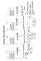
- FIG. 35 shows the relationship between the display position of the left and right images of an object (object) on the screen and the playback position of the stereoscopic image in stereoscopic image display using binocular parallax.
- the right and left line of sight intersects in front of the screen surface.
- the position is in front of the screen surface.
- DPa represents a horizontal disparity vector (disparity information) related to the object A.
- the right and left lines of sight intersect on the screen surface.
- Upper that is, the monitor position.
- the left image Lc is shifted to the left side and the right image Rc is shifted to the right side, the right and left lines of sight intersect at the back of the screen surface.
- the playback position is behind the screen.
- DPc represents a horizontal disparity vector related to the object C.
- stereoscopic image display it is common for a viewer to recognize the perspective of a stereoscopic image using binocular parallax.
- Superimposition information to be superimposed on an image for example, graphics information such as OSD (On Screen Display) can be rendered in conjunction with stereoscopic image display not only in two-dimensional space but also in three-dimensional depth. Be expected.
- OSD On Screen Display
- stereoscopic image surface a surface of an object (object) in the closest image (hereinafter referred to as “stereoscopic image surface”) in terms of perspective. Otherwise, the viewer may feel a contradiction in perspective.
- graphics information such as OSD is superimposed on an image, it is expected that parallax adjustment is performed according to the perspective of each object in the image to maintain perspective consistency.
- An object of the present invention is to maintain perspective consistency with each object in an image in displaying superimposition information in displaying a stereoscopic image, for example, graphics information such as OSD.
- the concept of this invention is An image data output unit for outputting left-eye image data and right-eye image data constituting a stereoscopic image; A depth information output unit that outputs depth information corresponding to the stereoscopic image; A transmission unit for transmitting the image data and the depth information, The depth information includes division information of the image display surface and depth information of each divided area, The transmission unit is in a stereoscopic image data transmission apparatus that transmits a multiplexed data stream including a data stream including the image data, and inserts a descriptor including the depth information into the multiplexed data stream.
- the image data output unit outputs left-eye image data and right-eye image data constituting a stereoscopic image. Further, the depth information output unit outputs depth information corresponding to the stereoscopic image. Then, the image data and the depth information are transmitted by the transmission unit.
- This depth information includes division information of the image display surface and depth information of each divided region.
- the depth information may be image plane information indicating whether or not a stereoscopic image plane (the closest object plane in terms of perspective in the image) is in front of the monitor position.
- the image plane information may be, for example, code information constituting disparity information (disparity vector) of the left eye image and the right eye image. When the sign of the parallax information is negative, it can be seen that the stereoscopic image plane is in front of the monitor position.
- the depth information is image plane information indicating whether or not a stereoscopic image plane is in front of the monitor position, or parallax information between the image plane information, the left eye image, and the right eye image. May include flag information indicating the presence of disparity information.
- the depth information is code information constituting disparity information, or absolute value information constituting this code information and disparity information. In this case, code information of parallax information constitutes image plane information.
- the parallax information is included, so that on the receiving side, not only whether or not the position of the stereoscopic image plane is in front of the monitor position, but also the position can be grasped in more detail. It becomes possible. Further, since the flag information is inserted, it is possible to selectively transmit only the image plane information or both the screen information and the parallax information as the depth information.
- the division information may include information indicating the division type and information indicating the number of divisions. As described above, since the division information is composed of two pieces of information, it is possible to specify a larger number of division patterns with a small number of information.
- the division type includes a division type that divides the image display surface using diagonal lines. Further, for example, the division type includes a division type in which the image display surface is divided using horizontal lines and / or vertical lines.
- a multiplexed data stream having a data stream including image data is transmitted.
- a descriptor including depth information is inserted into this multiplexed data stream.
- the multiplexed data stream includes a program map table as program specific information indicating which program each elementary stream included in the multiplexed data stream belongs to. Are inserted under the program map table.
- descriptors are sequentially transmitted during the program period, and the depth information can be dynamically changed during the program period.
- the multiplexed data stream includes an event information table as service information for managing each event, and the descriptor is inserted under this event information table.
- the descriptor is transmitted at the beginning of the program, and the depth information is fixed during the program period.
- the depth information corresponding to the stereoscopic image is transmitted together with the left eye image data and the right eye image data constituting the stereoscopic image. Therefore, on the receiving side, by using depth information, parallax adjustment is performed according to the perspective of each object in the image as superimposition information superimposed on the left eye image and the right eye image, for example, graphics information such as OSD. Can be used. Thereby, for example, in the display of graphics information such as OSD, it is possible to maintain perspective consistency with each object in the image.
- the depth information includes division information of the image display surface and depth information of each divided region, and is included in a descriptor inserted into a multiplexed data stream having a data stream including stereoscopic image data. Included and sent. That is, it is possible to easily transmit the depth information to the receiving side.
- the transmission unit inserts the descriptor into the multiplexed data stream in correspondence with the start time of each predetermined period of the image data, and in the multiplexed data stream in correspondence with the start time of each period.
- the inserted descriptor may include depth information in a period after the period.
- the disparity information used when providing disparity between the left eye superimposition information and the right eye superimposition information in each period is included in the depth information of the period and periods before and after the period.
- a descriptor that includes a data stream including left-eye image data and right-eye image data constituting a stereoscopic image, and includes depth information including division information on the image display surface and depth information of each divided region corresponding to the stereoscopic image data.
- a receiver for receiving the multiplexed data stream into which is inserted; Output data of left eye superimposition information corresponding to the left eye image data acquired from the multiplexed data stream and data of right eye superimposition information corresponding to the right eye image data acquired from the multiplexed data stream.
- a superimposition information data output unit A data superimposing unit that superimposes the data of the left eye superimposition information and the data of the right eye superimposition information on the left eye image data and the right eye image data acquired from the multiplexed data stream;
- the superimposition information data output unit is in a stereoscopic image data receiving apparatus that gives a parallax between the left eye superimposition information and the right eye superimposition information based on the depth information acquired from the multiplexed data stream.
- the reception unit receives a multiplexed data stream having a data stream including left eye image data and right eye image data.
- a descriptor including depth information including division information on the image display surface and depth information of each divided area corresponding to the stereoscopic image data is inserted.
- this descriptor is inserted under a program map table or an event information table.
- the superimposition information data output unit outputs left eye superimposition information data corresponding to left eye image data and right eye superimposition information data corresponding to right eye image data. Then, the data superimposing unit superimposes the data of the left eye superimposition information and the data of the right eye superimposition information on the left eye image data and the right eye image data obtained from the multiplexed data stream. Thereby, graphics information such as OSD can be superimposed and displayed on the stereoscopic image.
- parallax is given between the left eye superimposition information and the right eye superimposition information based on the depth information acquired from the multiplexed data stream. For this reason, in the present invention, it is possible to maintain perspective consistency with each object in the image, for example, in displaying graphics information such as OSD.
- the superimposition information data output unit adds a parallax between the left eye superimposition information and the right eye superimposition information based on the parallax information included in the depth information
- a new descriptor is generated in the reception unit. Is received, and when there is an update of the disparity information, the disparity information obtained by the interpolation process is used between the plurality of frames so that the new disparity information is reached over a plurality of frames.
- the time direction (frame direction) change of the parallax information used for parallax provision can be made smooth, and the parallax to be given to the left-eye and right-eye graphics information changes abruptly, causing the viewer to feel uncomfortable. This can be suppressed.
- a descriptor is inserted corresponding to the start time of each predetermined period of the image data, and inserted into the multiplexed data stream corresponding to the start time of each period.
- the included descriptor includes depth information for a period after the period, and the superimposition information data output unit applies parallax between the left eye superimposition information and the right eye superimposition information for each period.
- the disparity information obtained by the interpolation process using the disparity information included in the depth information of the period and periods before and after the period may be used.
- the time direction (frame direction) change of the parallax information used for parallax provision can be made smooth, that is, the update curve of the parallax information used for parallax provision can be smoothed, and the left eye and right eye graphics information It is possible to suppress the parallax to be given to the viewer from changing abruptly and causing the viewer to feel uncomfortable.
- a descriptor that includes a data stream including left-eye image data and right-eye image data constituting a stereoscopic image, and includes depth information including division information on the image display surface and depth information of each divided region corresponding to the stereoscopic image data.
- a receiver for receiving the multiplexed data stream into which is inserted;
- a transmission unit that transmits the left-eye image data and the right-eye image data acquired from the multiplexed data stream received by the reception unit and the depth information to an external device via a transmission path;
- the stereoscopic image data receiving device is provided.
- the reception unit receives a multiplexed data stream having a data stream including left eye image data and right eye image data.
- a descriptor including depth information including division information on the image display surface and depth information of each divided area corresponding to the stereoscopic image data is inserted.
- this descriptor is inserted under a program map table or an event information table.
- the transmission unit transmits the left-eye image data and right-eye image data acquired from the multiplexed data stream received by the reception unit, and the depth information to the external device via the transmission path.
- the image data is transmitted to the external device via a transmission path using a differential signal with a plurality of channels, and the depth information is inserted into the blanking period of the image data and transmitted to the external device. Is done.
- the depth information corresponding to the stereoscopic image is transmitted to the external device via the transmission path together with the left-eye image data and the right-eye image data constituting the stereoscopic image. Therefore, in an image display apparatus such as an external device such as a television receiver, each object in the image is used as superimposition information superimposed on the left eye image and right eye image, for example, graphics information such as OSD, by using depth information.
- graphics information such as OSD
- disparity is given to the OSD graphics information of the left eye and the right eye using the disparity information (representative) of the divided region corresponding to the superimposed display position. It is a figure which shows what can be done. It is a figure which shows the structural example (case1) of the multiplexed data stream under which PMT, ie, the descriptor (z-Surface
- HDMI transmission part HDMI source
- HDMI receiving part HDMI sink
- FIG. 1 It is a block diagram which shows the structural example of an HDMI transmission part (HDMI source) and an HDMI receiving part (HDMI sink).
- HDMI transmission part HDMI source
- HDMI receiving part HDMI sink
- FIG. 1 shows the example of a structure of TMDS transmission data (when the image data of horizontal x length is 1920 pixels x 1080 lines is transmitted).
- FIG. 1 shows the pin arrangement (type A) of the HDMI terminal to which the HDMI cable of the source device and the sink device is connected.
- FIG. 1 shows a configuration example of a stereoscopic image display system 10 as an embodiment.
- the stereoscopic image display system 10 includes a broadcasting station 100, a set top box (STB) 200, and a television receiver (TV) 300.
- STB set top box
- TV television receiver
- the set top box 200 and the television receiver 300 are connected via an HDMI (High Definition Multimedia Interface) cable 400.
- the set top box 200 is provided with an HDMI terminal 202.
- the television receiver 300 is provided with an HDMI terminal 302.
- One end of the HDMI cable 400 is connected to the HDMI terminal 202 of the set top box 200, and the other end of the HDMI cable 400 is connected to the HDMI terminal 302 of the television receiver 300.
- the broadcasting station 100 transmits the bit stream data BSD on a broadcast wave.
- the broadcast station 100 includes a transmission data generation unit 110 that generates bit stream data BSD.
- the bit stream data BSD includes image data, audio data, depth information, and the like.
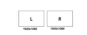
- the image data (hereinafter referred to as “stereoscopic image data” as appropriate) includes left-eye image data and right-eye image data constituting a stereoscopic image.
- the audio data is audio data corresponding to this stereoscopic image.
- the depth information corresponds to the stereoscopic image, and includes division information on the image display surface and depth information on each divided area.
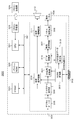
- FIG. 2 shows a configuration example of the transmission data generation unit 110 that generates transmission data in the broadcast station 100.
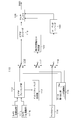
- the transmission data generation unit 110 includes cameras 111L and 111R, a video framing unit 112, a disparity map generation unit 113, a microphone 114, a data extraction unit 115, and changeover switches 116 to 118.
- the transmission data generation unit 110 includes a video encoder 119, an audio encoder 120, a depth information set creation unit 122, and a multiplexer 126.
- the camera 111L captures a left eye image and obtains left eye image data for stereoscopic image display.
- the camera 111R captures the right eye image and obtains right eye image data for stereoscopic image display.
- the video framing unit 112 processes the left eye image data obtained by the camera 111L and the right eye image data obtained by the camera 111R into stereoscopic image data (3D image data) corresponding to the transmission format.
- the video framing unit 112 constitutes an image data output unit.
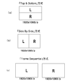
- the first transmission method is a top-and-bottom method. As shown in FIG. 4A, in the first half of the vertical direction, the data of each line of the left eye image data is transmitted, and the vertical direction In the latter half of the method, the data of each line of the left eye image data is transmitted. In this case, since the lines of the left eye image data and the right eye image data are thinned out to 1 ⁇ 2, the vertical resolution is halved with respect to the original signal.
- the second transmission method is a side-by-side (Side By Side) method.
- pixel data of the left eye image data is transmitted, and in the second half in the horizontal direction.
- the pixel data of the right eye image data is transmitted.
- the pixel data in the horizontal direction is thinned out to 1/2.
- the horizontal resolution is halved with respect to the original signal.
- the third transmission method is a frame sequential method in which left-eye image data and right-eye image data are sequentially switched and transmitted for each frame as shown in FIG.
- This frame sequential method may be referred to as a full frame method or a backward compatible method.
- the disparity map generation unit 113 detects disparity information (disparity vector) for each pixel constituting the image based on the left eye image data and the right eye image data, for example, Create a map.
- the disparity information includes code information and absolute value information. For example, the sign of the disparity information of a pixel perceived before the monitor position is negative, and the sign of the disparity information of a pixel perceived behind the monitor position is positive. In addition, the absolute value of the parallax information increases as the pixel is perceived further away from the monitor position.
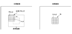
- disparity vector detection An example of disparity vector detection will be described.
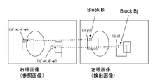
- an example in which the parallax vector of the right eye image with respect to the left eye image is detected will be described.
- the left eye image is a detected image
- the right eye image is a reference image.
- the disparity vectors at the positions (xi, yi) and (xj, yj) are detected.
- a case where a disparity vector at the position of (xi, yi) is detected will be described as an example.
- a 4 ⁇ 4, 8 ⁇ 8, or 16 ⁇ 16 pixel block (parallax detection block) Bi is set in the left eye image with the pixel at the position (xi, yi) at the upper left. Then, a pixel block matching the pixel block Bi is searched in the right eye image.
- a search range centered on the position of (xi, yi) is set in the right eye image, and each pixel in the search range is sequentially set as a pixel of interest, for example, 4 ⁇ 4 similar to the above-described pixel block Bi. 8 ⁇ 8 or 16 ⁇ 16 comparison blocks are sequentially set.
- the sum of the absolute differences for each corresponding pixel is obtained.
- the pixel block Bi when the pixel value of the pixel block Bi is L (x, y) and the pixel value of the comparison block is R (x, y), the pixel block Bi, a certain comparison block, The sum of absolute differences between the two is represented by ⁇
- n pixels are included in the search range set in the right eye image, n total sums S1 to Sn are finally obtained, and the minimum sum Smin is selected. Then, the position of the upper left pixel (xi ′, yi ′) is obtained from the comparison block from which the sum Smin is obtained. Thus, the disparity vector at the position (xi, yi) is detected as (xi′ ⁇ xi, yi′ ⁇ yi).
- the left eye image has the pixel at the position (xj, yj) at the upper left, for example, 4 ⁇ 4, 8 ⁇ 8, or 16
- a x16 pixel block Bj is set and detected in the same process.
- the microphone 114 detects sound corresponding to the images photographed by the cameras 111L and 111R, and obtains sound data.
- the data extraction unit 115 is used in a state where the data recording medium 115a is detachably mounted.
- the data recording medium 115a is a disk-shaped recording medium, a semiconductor memory, or the like.
- audio data and disparity maps are recorded in association with stereo image data including left eye image data and right eye image data.
- the data extraction unit 115 extracts and outputs stereoscopic image data, audio data, and a disparity map from the data recording medium 115a.
- the data extraction unit 115 constitutes an image data output unit.
- the stereoscopic image data recorded on the data recording medium 115 a corresponds to the stereoscopic image data obtained by the video framing unit 112.
- the audio data recorded on the data recording medium 115 a corresponds to the audio data obtained by the microphone 114.
- the disparity map recorded on the data recording medium 115a corresponds to a disparity vector generated by the disparity map generation unit 113.
- the changeover switch 116 selectively extracts the stereoscopic image data obtained by the video framing unit 112 or the stereoscopic image data output from the data extraction unit 115.
- the changeover switch 116 is connected to the a side in the live mode and takes out the stereoscopic image data obtained by the video framing unit 112, and is connected to the b side in the playback mode and is output from the data extraction unit 115. Extract stereo image data.
- the changeover switch 117 selectively extracts the disparity map generated by the disparity map generation unit 113 or the disparity map output from the data extraction unit 115.
- the changeover switch 117 is connected to the a side in the live mode and takes out the disparity map generated by the disparity map generation unit 113, and is connected to the b side in the reproduction mode and the data extraction unit 115.
- the disparity map output from is taken out.
- the changeover switch 118 selectively takes out the voice data obtained by the microphone 114 or the voice data output from the data fetch unit 115.
- the changeover switch 118 is connected to the a side in the live mode and takes out the audio data obtained by the microphone 114, and is connected to the b side in the playback mode, and the audio data output from the data extraction unit 115 is taken out. Take out.
- the video encoder 119 performs encoding such as MPEG4-AVC, MPEG2, or VC-1 on the stereoscopic image data extracted by the changeover switch 116 to generate a video data stream (video elementary stream).
- the audio encoder 120 performs encoding such as AC3 or AAC on the audio data extracted by the changeover switch 118 to generate an audio data stream (audio elementary stream).
- the depth information set creation unit 122 creates a depth information set corresponding to stereoscopic image data of a predetermined program output from the changeover switch 116 based on the disparity map extracted by the changeover switch 117.
- This depth information set includes division information on the image display surface and depth information on each divided area.
- This division information includes information indicating a division type and information indicating the number of divisions.
- the division type includes a division type that divides the image display surface using diagonal lines, and a division type that divides the image display surface using horizontal lines and / or vertical lines.
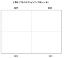
- FIG. 7 shows an example of a position map when the image display surface is divided into four in the division type 1 in which the image display surface is divided using diagonal lines.
- the image display surface is divided into four using diagonal lines, the upper divided area is represented by “0000”, the right divided area is represented by “0001”, and the lower divided area is “ “0010”, and the left divided area is represented by "0011".
- FIG. 7 shows an example of a position map when the image display surface is divided into 8 in the division type 1 in which the image display surface is divided using diagonal lines.
- the image display surface is divided into eight using diagonal lines and rectangular sides, and each divided region is represented by “0000” to “0111”.
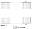
- FIG. 10 shows an example of a position map when the image display surface is divided into four in type 2 where the image display surface is equally divided in the horizontal direction and the vertical direction.
- the image display surface is divided into four by a vertical line and a horizontal line, the upper right divided area is represented by “0000”, the lower right divided area is represented by “0001”, The lower left divided area is represented by “0010”, and the upper left divided area is represented by “0011”.
- FIG. 10 shows an example of a position map when the image display surface is divided into 9 parts in Type 2 where the image display surface is equally divided in the horizontal direction and the vertical direction.
- the image display surface is divided into nine by a vertical line and a horizontal line, and each divided area is represented by “0000” to “1000”.
- FIG. 13 shows an example of a position map when the image display surface is divided into five in the division type 3 in which the image display surface is divided using diagonal lines and rectangular sides.
- the image display surface is divided into five using diagonal lines and rectangular sides, the upper divided area is represented by “0000”, the right divided area is represented by “0001”, and the lower divided area is represented by “0000”.
- the divided area is represented by “0010”, the left divided area is represented by “0011”, and the central divided area is represented by “0100”.
- the division example in FIG. 13 is preferable because the depth information corresponding to the superimposed display position can be transmitted when the OSD graphics information is shifted to the edge portion of the image or superimposed on the central portion of the image. It will be a thing.
- This depth information includes image plane information.
- This image plane information is information indicating whether or not a stereoscopic image plane is in front of the monitor position.
- This stereoscopic image plane means the closest object plane in terms of perspective in the image of the corresponding region.
- this image plane information is code information constituting disparity information (disparity vector) corresponding to the stereoscopic image plane.
- the sign information indicates “negative” when the stereoscopic image plane is in front of the monitor position.
- the depth information may include parallax information in addition to the above-described image plane information.
- this parallax information for example, among the parallax information (parallax vectors) of each pixel (pixel) constituting the image of the corresponding region, the parallax information of the pixel perceived closest to the perspective is used as a representative. Is done. In this case, when there is “negative” parallax information, the parallax information having the largest absolute value among them is set. In this case, when there is no “negative” parallax information, the parallax information having the smallest absolute value is obtained.
- the image plane information is the code information constituting the parallax information as described above, it is only necessary to further include the absolute value information constituting the parallax information.
- the representative of the parallax information in each divided area can be obtained by, for example, comparing the parallax information for each pixel or each block of a predetermined size in the display scan order in the divided area.
- FIG. 14 shows how to obtain the representative parallax information of each divided area in the divided pattern in which the image display surface is divided into four by diagonal lines as described above. In this case, “Disparity_00”, “Disparity_01”, “Disparity_10”, and “Disparity_11” are obtained as representatives of disparity information in each divided region.
- the representative of the parallax information of each divided area obtained as described above is used. Is done.
- the OSD graphics information is superimposed and displayed on the edge portion of the image, the left eye, the disparity information (representative) of the divided region corresponding to the superimposed display position is used, It becomes possible to add parallax to the OSD graphics information of the right eye.
- flag information indicating the presence of disparity information is inserted for each divided region or common to each divided region.
- the parallax information is included, so that on the receiving side, not only whether or not the position of the stereoscopic image plane is in front of the monitor position, but also the position can be grasped in more detail. It becomes possible. Further, since the flag information is inserted, it is possible to selectively transmit only the image plane information or both the screen information and the parallax information as the depth information.
- parallax When superimposing OSD graphics information on an image on the receiving side, parallax must be added to the left and right OSD graphics information when the stereoscopic image plane is in front of the monitor position. In that case, it is necessary to add parallax to the left and right OSD graphics information so that the OSD graphics information is perceived in front of the stereoscopic image plane.
- the amount of parallax to be added to the left and right OSD graphics information can be arbitrarily set on the receiving side, and therefore it is sufficiently meaningful to transmit only image plane information.
- the multiplexer 126 multiplexes each data stream from the video encoder 119 and the audio encoder 120 to obtain a multiplexed data stream as bit stream data (transport stream) BSD. Further, the multiplexer 126 inserts the depth information set created by the depth information set creation unit 122 into the bit stream data BSD. Specifically, the multiplexer 126 inserts a descriptor (z-Surface descriptor) including a depth information set at a predetermined position of the PSI information or SI information inserted into the bit stream data BSD. Details of this descriptor will be described later.
- z-Surface descriptor z-Surface descriptor
- the operation of the transmission data generation unit 110 shown in FIG. 2 will be briefly described.
- the camera 111L captures a left eye image.
- the left eye image data for stereoscopic image display obtained by the camera 111L is supplied to the video framing unit 112.
- the camera 111R captures a right eye image.
- Right-eye image data for stereoscopic image display obtained by the camera 111R is supplied to the video framing unit 112.
- the left-eye image data and the right-eye image data are processed into a state corresponding to the transmission format, and stereoscopic image data is obtained (see FIGS. 4A to 4C).
- the stereoscopic image data obtained by the video framing unit 112 is supplied to the fixed terminal on the a side of the changeover switch 116.
- the stereoscopic image data obtained by the data extraction unit 115 is supplied to the fixed terminal on the b side of the changeover switch 116.
- the changeover switch 116 is connected to the a side, and the stereoscopic image data obtained by the video framing unit 112 is taken out from the changeover switch 116.
- the selector switch 116 is connected to the b side, and the stereoscopic image data output from the data extracting unit 115 is extracted from the selector switch 116.
- the stereoscopic image data extracted by the changeover switch 116 is supplied to the video encoder 119.
- the stereoscopic image data is encoded by MPEG4-AVC, MPEG2, VC-1, or the like, and a video data stream including the encoded video data is generated. This video data stream is supplied to the multiplexer 126.
- the audio data obtained by the microphone 114 is supplied to the fixed terminal on the a side of the changeover switch 118. Also, the audio data obtained by the data extraction unit 115 is supplied to the fixed terminal on the b side of the changeover switch 118.
- the changeover switch 118 In the live mode, the changeover switch 118 is connected to the a side, and the audio data obtained by the microphone 114 is extracted from the changeover switch 118.
- the changeover switch 118 is connected to the b side, and the audio data output from the data extraction unit 115 is taken out from the changeover switch 118.
- the audio data extracted by the changeover switch 118 is supplied to the audio encoder 120.
- the audio encoder 120 performs encoding such as MPEG-2Audio AAC or MPEG-4 AAC on the audio data, and generates an audio data stream including the encoded audio data. This audio data stream is supplied to the multiplexer 126.
- Left eye image data and right eye image data obtained by the cameras 111L and 111R are supplied to the disparity map generation unit 113 through the video framing unit 112.
- the disparity map generation unit 113 detects a disparity vector for each pixel (pixel) based on the left eye image data and the right eye image data, and generates a disparity map.
- This disparity map is supplied to the fixed terminal on the a side of the changeover switch 117.
- the disparity map output from the data extraction unit 115 is supplied to the fixed terminal on the b side of the changeover switch 117.
- the changeover switch 117 In the live mode, the changeover switch 117 is connected to the a side, and the disparity map generated by the disparity map generation unit 113 is extracted from the changeover switch 117. In the reproduction mode, the changeover switch 117 is connected to the b side, and the disparity map output from the data extraction unit 115 is taken out from this changeover switch 117.
- the disparity map extracted by the changeover switch 117 is supplied to the depth information set creation unit 122.
- the depth information set creation unit 122 creates a depth information set corresponding to stereoscopic image data of a predetermined program output from the changeover switch 116 based on the disparity map.
- This depth information set includes division information of the image display surface and depth information of each divided area. This depth information set is supplied to the multiplexer 126.
- the data streams from the video encoder 119 and the audio encoder 120 are multiplexed, and a multiplexed data stream as bit stream data (transport stream) BSD is obtained.
- the depth information set created by the depth information set creation unit 122 is inserted into the bit stream data BSD. That is, in the multiplexer 126, a descriptor (z-Surface descriptor) including a depth information set is inserted at a predetermined position of PSI information or SI information inserted into the bit stream data BSD.
- a descriptor z-Surface descriptor
- FIG. 16 to 18 show configuration examples of multiplexed data streams (transport streams).
- This multiplexed data stream includes PES packets obtained by packetizing each elementary stream.
- the PES packet “Video PES” of the video elementary stream and the PES packet “AudioPES” of the audio elementary stream are included.
- the transport stream includes a PMT (Program Map Table) as PSI (Program Specific Information).
- PSI Program Specific Information
- This PSI is information describing to which program each elementary stream included in the transport stream belongs.
- the transport stream includes an EIT (Event Information Table) as SI (Serviced Information) for managing each event.
- SI Serviced Information
- the PMT has a program descriptor (ProgramDescriptor) that describes information related to the entire program.
- the PMT includes an elementary loop having information related to each elementary stream. In this configuration example, there are a video elementary loop and an audio elementary loop.
- information such as a packet identifier (PID) is arranged for each stream, and a descriptor (descriptor) describing information related to the elementary stream is also arranged, although not shown.
- PID packet identifier
- descriptor descriptor
- the configuration example of the multiplexed data stream shown in FIGS. 16 and 17 is an example in which a descriptor (z-Surface descriptor) including a depth information set is inserted under the PMT. That is, in the configuration example (case 1) of the multiplexed data stream shown in FIG. 16, the descriptor (z-Surface descriptor) is arranged in the program descriptor (ProgramDescriptor) in the PMT. In addition, in the configuration example (case 2) of the multiplexed data stream shown in FIG. 17, a descriptor (z-Surfaceordescriptor) is arranged in the descriptor (descriptor) portion of the video elementary loop (Video ES loop). In addition, the configuration example (case 3) of the multiplexed data stream illustrated in FIG. 18 is an example in which a descriptor (z-Surface descriptor) including a depth information set is inserted under the EIT.
- the descriptor can be sent at a predetermined timing during the program period. It can be changed dynamically.
- the depth information a, the depth information b, and the depth information c are dynamically changed in the order during the program period.
- the depth information update period is, for example, 100 msec or longer than 100 msec.
- FIG. 20 shows an outline of processing for scene detection and descriptor transmission.
- the motion vector is detected by comparing all the blocks included in the current frame with the image data of the previous frame. Then, the sum ⁇ (mv ((t ⁇ 1) ⁇ mv (t)) of the difference values of the motion vectors (magnitudes) for each block is used as a correlation value check value between the current frame and the previous frame. Similarly, the sum ⁇ (mv () of difference values of motion vectors (magnitudes) for each block is used as a correlation value check value between the previous frame and the previous two frames. (t-2) -mv (t-1)) is calculated.
- a descriptor including depth information for each predetermined period can be sent during a program period.
- a descriptor z-Surface descriptor corresponding to the start time of each period is used.
- the depth information of the period in the descriptor it is also conceivable to include the depth information of a period after the period, for example, the period after the period, as so-called advance information.
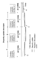
- FIG. 21 shows the relationship between the transmission timing of each descriptor (z-Surface descriptor) and the depth information included in each descriptor in that case.
- a descriptor (z-Surface descriptor) transmitted at the start of period A includes depth information b of period B.
- the descriptor (z-Surface descriptor) transmitted at the start of period B includes depth information c of period C.
- the descriptor (z-Surface descriptor) transmitted at the start of each period includes the depth information of the subsequent period, for example, the next period, as advance information, so that the time direction changes gently on the receiving side.
- Accurate parallax information can be obtained. That is, on the receiving side, the disparity information used when providing disparity between the left eye superimposition information and the right eye superimposition information for each period is included in the depth information set for the period and periods before and after the period. Interpolation processing using parallax information can be performed. Accordingly, it is possible to obtain parallax information in which a change in the time direction (in the frame direction) is gentle, that is, the update curve is smooth.
- a broken line S1 indicates an example of a disparity information curve (Video (disparity curve) in transmitted stereoscopic image data
- a solid line S2 indicates an example of disparity information (Disparity update) updated corresponding to each period. Is shown.
- a broken line S3 indicates an example of a disparity information curve (Receiverceivinterpolation curve) obtained by interpolation processing on the receiving side.
- the following interpolation processing is performed on the receiving side. That is, in the first half of each period, the interpolated parallax information at each time point is obtained by sequentially increasing the mixing ratio of the disparity information of the previous period and the disparity information of the period during the period. Further, in the latter half of each period, the interpolated parallax information at each time point is obtained by sequentially increasing the mixing ratio of the disparity information of the period and the disparity information of the later period in the later period.
- the descriptor when a descriptor (z-Surface descriptor) including a depth information set is inserted under the EIT, as shown in FIG. 22, the descriptor can be transmitted at the beginning of the program, and the depth information is fixed during the program period.
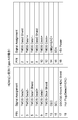
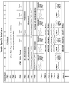
- FIG. 23 shows a structural example (Syntax) of a descriptor (z-Surface descriptor).
- FIG. 24 shows the contents (Semantics) of main information in the structural example shown in FIG.
- the 8-bit field of “descriptor_tag” indicates the type of descriptor (descriptor), and here indicates that it is a descriptor (z-Surface descriptor).
- the 8-bit field of “descriptor_length” is 8-bit data indicating the length (size) of the descriptor. This data indicates the number of bytes after “descriptor_length” as the length of the descriptor.
- the 2-bit field of “display_partition_type” indicates the partition type of the image display surface (see FIGS. 7 to 13).
- a 4-bit field of “number_of_partition” indicates the number of divisions on the image display surface.
- the descriptor z-Surface descriptor
- the 1-bit field “z_depth_negative” indicates image plane information.
- image plane information as described above, whether or not the stereoscopic image plane (the closest object plane in terms of perspective in the image of the corresponding divided area) is negative (near) with respect to the monitor position.
- Indicate. “1” indicates that the stereoscopic image plane is negative (near) with respect to the monitor position.
- “1” indicates that the stereoscopic image plane is the same as the monitor position or is positive (back) with respect to the monitor position.
- code information constituting disparity information is used as a 1-bit field of “z_depth_negative_”.
- the disparity information in this case is the disparity information of the most perceived pixel in terms of perspective among the disparity information (disparity vector) of each pixel (pixel) constituting the image of the corresponding region. This is disparity information of pixels constituting the image plane.
- Disposity_value_flag is 1-bit flag information indicating whether or not disparity information exists in addition to the above-described image plane information.
- the parallax information in this case is, for example, parallax information of the pixels constituting the above-described stereoscopic image plane. “1” indicates that disparity information exists, and “0” indicates that disparity information does not exist. When this flag information is “1”, an 8-bit field of “absolute_disparity_value” exists. This “absolute_disparity_value” indicates absolute value information constituting disparity information.
- the absolute value information and the code information as the above-described image plane information constitute disparity information.
- FIG. 25 shows another structural example (Syntax) of the descriptor (z-Surface descriptor).
- “disparity_value_flag” is common to each divided region and is arranged outside the for loop.
- “disparity_value_flag” is “1” indicating the presence of disparity information
- a 7-bit field of “absolute_disparity_value” exists, and in other cases, 7-bit “reserved” exists.
- the bit stream data BSD output from the multiplexer 126 includes the stereoscopic image data of the predetermined program having the left eye image data and the right eye image data, and the stereoscopic image data of the predetermined program.
- a corresponding depth information set is included. Therefore, by using this depth information set on the receiving side, parallax adjustment is performed according to the perspective of each object in the image as superimposition information superimposed on the left eye image and the right eye image, for example, graphics information such as OSD. What was given can be used. Thereby, for example, in the display of graphics information such as OSD, it is possible to maintain perspective consistency with each object in the image.
- the depth information set includes division information on the image display surface and depth information on each division area, and includes bit stream data including a data stream including stereoscopic image data. (Multiplexed data stream) Transmitted by being included in a descriptor inserted into the BSD. That is, the depth information set can be easily transmitted to the receiving side using the descriptor.
- the set-top box 200 receives bit stream data (transport stream) BSD transmitted from the broadcast station 100 on broadcast waves.
- This bit stream data BSD includes stereoscopic image data including left eye image data and right eye image data, audio data, and a depth information set.
- the set top box 200 has a bit stream processing unit 201.
- the bit stream processing unit 201 extracts stereoscopic image data, audio data, a depth information set, and the like from the bit stream data.
- the bit stream processing unit 201 appropriately generates left eye image data and right eye image data on which graphics information such as OSD is superimposed.
- parallax is given between the left eye graphics information superimposed on the left eye image and the right eye graphics information superimposed on the right eye image.
- the parallax is provided between the left-eye graphics information and the right-eye graphics, so that the user can recognize graphics information such as OSD superimposed on the stereoscopic image, for example, in front of the image.
- FIG. 26 shows a configuration example of the set top box 200.
- the set top box 200 includes a bit stream processing unit 201, an HDMI terminal 202, an antenna terminal 203, a digital tuner 204, a video processing circuit 205, an HDMI transmission unit 206, and an audio processing circuit 207.
- the set top box 200 includes a CPU 211, a flash ROM 212, a DRAM 213, an internal bus 214, a remote control receiving unit 215, and a remote control transmitter 216.
- the antenna terminal 203 is a terminal for inputting a television broadcast signal received by a receiving antenna (not shown).
- the digital tuner 204 processes the television broadcast signal input to the antenna terminal 203 and outputs predetermined bit stream data (transport stream) BSD corresponding to the user's selected channel.
- the bit stream processing unit 201 extracts and outputs stereoscopic image data, audio data, and the like from the bit stream data BSD.
- the bit stream processing unit 201 appropriately synthesizes display data of graphics information such as OSD with stereoscopic image data.
- the bit stream processing unit 201 appropriately assigns parallax between the left-eye graphics information superimposed on the left-eye image and the right-eye graphics information superimposed on the right-eye image based on the depth information set.
- the video processing circuit 205 performs image quality adjustment processing on the stereoscopic image data output from the bit stream processing unit 201 as necessary, and supplies the processed stereoscopic image data to the HDMI transmission unit 206.
- the audio processing circuit 207 performs a sound quality adjustment process or the like on the audio data output from the bit stream processing unit 201 as necessary, and supplies the processed audio data to the HDMI transmission unit 206.
- the HDMI transmitting unit 206 transmits, for example, uncompressed image data and audio data from the HDMI terminal 202 by communication conforming to HDMI. In this case, image data and audio data are packed and transmitted from the HDMI transmission unit 206 to the HDMI terminal 202 for transmission via the HDMI TMDS channel.
- the HDMI transmission unit 206 transmits the depth information set described above to the television receiver 300 through the HDMI interface. Details of the HDMI transmission unit 206 will be described later.
- the CPU 211 controls the operation of each part of the set top box 200.
- the flash ROM 212 stores control software and data.
- the DRAM 213 constitutes a work area for the CPU 211.
- the CPU 211 develops software and data read from the flash ROM 212 on the DRAM 213 to activate the software, and controls each part of the set top box 200.
- the remote control receiving unit 215 receives the remote control signal (remote control code) transmitted from the remote control transmitter 216 and supplies it to the CPU 211.
- the CPU 211 controls each part of the set top box 200 based on the remote control code.
- the CPU 211, flash ROM 212 and DRAM 213 are connected to the internal bus 214.
- the bit stream processing unit 201 includes a demultiplexer 220, a video decoder 221, an audio decoder 224, an OSD display data generation unit 226, and a video superimposition unit 228.
- the demultiplexer 220 extracts video and audio packets from the bit stream data BSD and sends them to each decoder. Further, the demultiplexer 220 extracts the depth information set from the bit stream data BSD, and sends it to the OSD display data generation unit 226 and the HDMI transmission unit 206 described above.
- the video decoder 221 reconstructs a video elementary stream from the video packet extracted by the demultiplexer 220, performs a decoding process, and obtains stereoscopic image data including left-eye image data and right-eye image data.
- the audio decoder 224 reconstructs an audio elementary stream from the audio packet extracted by the demultiplexer 220, performs decoding processing, obtains audio data, and outputs the audio data to the outside of the bit stream processing unit 201.
- the OSD display data generation unit 226 generates left-eye graphics information data corresponding to left-eye image data included in stereoscopic image data and right-eye graphics information data corresponding to right-eye image data included in stereoscopic image data. .
- the OSD display data generating unit 226 performs the left-eye graphics information and the right-eye graphics information based on the image plane information included in the depth information set extracted by the demultiplexer 220, or the image plane information and the parallax information. In the meantime, parallax is appropriately given.
- a predetermined parallax determined in advance is applied so that the graphics information is perceived in front of the stereoscopic image plane. Is done. For example, based on the image plane information, when the stereoscopic image plane is located at the same position as the monitor position or behind it, no parallax is given. Further, for example, based on the parallax information, the parallax is given so that the graphics information is perceived in front of the stereoscopic image plane.
- the depth information of each divided area can be updated during the program period (see FIG. 19).
- the OSD display data generation unit 226 can dynamically change the parallax to be added to the left-eye and right-eye graphics information by using the depth information updated in this way, for example, parallax information.
- the OSD display data generation unit 226 repeatedly uses the disparity information included in a certain descriptor (z-Surface descriptor) in each frame until the next time the descriptor (z-Surface descriptor) is transmitted. It is also possible. However, in this case, at the time when the descriptor is transmitted and the disparity information is updated, the disparity to be added to the left-eye and right-eye graphics information may change abruptly, causing the viewer to feel uncomfortable.
- the OSD display data generation unit 226 immediately uses the disparity information included in the descriptor, as shown in FIG. Do not do. That is, the OSD display data generation unit 226 uses disparity information (shown by a broken line) by interpolation processing between the plurality of frames so as to reach new disparity information over a plurality of frames. With this process, the time direction (frame direction) change of the parallax information used for parallax addition can be made smooth, and the parallax to be given to the left and right eye graphics information changes abruptly, creating a sense of discomfort to the viewer Can be suppressed.
- disparity information shown by a broken line
- the above example of interpolation processing shown in FIG. 27 shows a case where the descriptor (z-Surface descriptor) sent corresponding to the start time of each period includes the depth information of the period.
- An example of interpolation processing will be described in the case where the descriptor (z-SurfaceSdescriptor) sent corresponding to the start time of each period includes depth information of a subsequent period, for example, the next period.
- FIG. 28 shows an example of interpolation processing in that case.
- the descriptor (z-Surface descriptor) sent at the start of period A includes depth information b of period B.
- the descriptor (z-Surface descriptor) sent at the start of period B includes depth information c of period C.
- the following interpolation processing is performed, and the interpolated disparity information at each time point is obtained. That is, in the first half of each period, the interpolated parallax information at each time point is obtained by sequentially increasing the mixing ratio of the disparity information of the previous period and the disparity information of the period during the period. Further, in the latter half of each period, the interpolated parallax information at each time point is obtained by sequentially increasing the mixing ratio of the disparity information of the period and the disparity information of the later period in the later period.
- the interpolated disparity information at each time point of the period T_AB from the intermediate time point of the period A to the intermediate time point of the period B is obtained by sequentially changing the mixing ratio of the disparity information of the period A and the disparity information of the period B.
- the disparity information for period A is sequentially changed from 100% to 0%
- the disparity information for period B is sequentially changed from 0% to 100%.
- the interpolated disparity information at each time point of the period T_BC from the intermediate time point of the period B to the intermediate time point of the period C is obtained by sequentially changing the mixing ratio of the disparity information of the period B and the disparity information of the period C. It is done.
- the disparity information for period B is sequentially changed from 100% to 0%
- the disparity information for period C is sequentially changed from 0% to 100%.
- the broken line S1 shows an example of the disparity information curve (Video disparity curve) in the transmitted stereoscopic image data
- the solid line S2 shows the disparity information (Disparity update) updated corresponding to each period.
- An example is shown.
- a broken line S3 indicates an example of a parallax information curve (Receiver interpolation) curve obtained by the interpolation process.
- the video superimposing unit 228 uses the left eye and left eye graphics information data generated by the OSD display data generating unit 226 for the stereoscopic image data (left eye image data and right eye image data) obtained by the video decoder 221. To obtain stereoscopic image data for display.
- the video superimposing unit 228 outputs the display stereoscopic image data to the outside of the bit stream processing unit 201.
- a television broadcast signal input to the antenna terminal 203 is supplied to the digital tuner 204.
- the digital tuner 204 processes the television broadcast signal and outputs predetermined bit stream data (transport stream) BSD corresponding to the user's selected channel.
- the bit stream data BSD output from the digital tuner 204 is supplied to the bit stream processing unit 201.
- stereoscopic image data, audio data, a depth information set, and the like are extracted from the bit stream data BSD.
- display data of graphics information such as OSD is appropriately combined with the stereoscopic image data.
- parallax is provided between the left-eye graphics information superimposed on the left-eye image and the right-eye graphics information superimposed on the right-eye image.
- the stereoscopic image data for display obtained by the bit stream processing unit 201 is supplied to the video processing circuit 205.
- image quality adjustment processing or the like is performed on the display stereoscopic image data as necessary.
- the processed stereoscopic image data output from the video processing circuit 205 is supplied to the HDMI transmission unit 206.
- the audio data obtained by the bit stream processing unit 201 is supplied to the audio processing circuit 207.
- the sound processing circuit 207 processing such as sound quality adjustment processing is performed on the sound data as necessary.
- the processed audio data output from the audio processing circuit 207 is supplied to the HDMI transmission unit 206.
- the stereoscopic image data and audio data supplied to the HDMI transmission unit 206 are transmitted from the HDMI terminal 202 to the HDMI cable 400 via the HDMI TMDS channel.
- the television receiver 300 receives stereoscopic image data sent from the set top box 200 via the HDMI cable 400.
- the television receiver 300 includes a 3D signal processing unit 301.
- the 3D signal processing unit 301 performs processing (decoding processing) corresponding to the transmission method on the stereoscopic image data to generate left-eye image data and right-eye image data.
- the 3D signal processing unit 301 acquires left-eye image data and right-eye image data that form stereoscopic image data.
- FIG. 29 illustrates a configuration example of the television receiver 300.
- the television receiver 300 includes a 3D signal processing unit 301, an HDMI terminal 302, an HDMI receiving unit 303, an antenna terminal 304, a digital tuner 305, and a bit stream processing unit 306.
- the television receiver 300 also includes an OSD display data generation unit 313, a video superimposition unit 314, a video processing circuit 307, a panel drive circuit 308, a display panel 309, an audio processing circuit 310, and an audio amplification circuit 311. And a speaker 312.
- the television receiver 300 includes a CPU 321, a flash ROM 322, a DRAM 323, an internal bus 324, a remote control receiving unit 325, and a remote control transmitter 326.
- the antenna terminal 304 is a terminal for inputting a television broadcast signal received by a receiving antenna (not shown).
- the digital tuner 305 processes the television broadcast signal input to the antenna terminal 304 and outputs predetermined bit stream data (transport stream) corresponding to the user's selected channel.
- the bit stream processing unit 306 has the same configuration as the bit stream processing unit 201 of the set top box 200 shown in FIG.
- the bit stream processing unit 306 extracts stereoscopic image data (left eye image data, right eye image data), audio data, a depth information set, and the like from the bit stream data.
- the HDMI receiving unit 303 receives uncompressed image data and audio data supplied to the HDMI terminal 302 via the HDMI cable 400 by communication conforming to HDMI.
- the HDMI receiving unit 303 has a version of, for example, HDMI 1.4, and can handle stereoscopic image data. Further, the HDMI receiving unit 303 receives the above-described depth information set from the set top box 200 via the HDMI interface. Details of the HDMI receiving unit 303 will be described later.
- the 3D signal processing unit 301 performs decoding processing on the stereoscopic image data received by the HDMI receiving unit 303 or obtained by the bit stream processing unit 306 to generate left eye image data and right eye image data. To do. In this case, the 3D signal processing unit 301 performs a decoding process corresponding to the transmission method format on the stereoscopic image data obtained by the bit stream processing unit 306. Further, the 3D signal processing unit 301 performs a decoding process corresponding to a TMDS transmission data structure described later on the stereoscopic image data received by the HDMI receiving unit 303.
- the OSD display data generation unit 313 generates left-eye graphics information data corresponding to left-eye image data included in stereoscopic image data and right-eye graphics information data corresponding to right-eye image data included in stereoscopic image data. .
- This graphics information is superimposition information for OSD display such as menus and program guides.
- the OSD display data generation unit 313 performs the interval between the left eye graphics information and the right eye graphics information based on the depth information set obtained by the bit stream processing unit 306 or received by the HDMI receiving unit 303. Add parallax.
- the OSD display data generation unit 313 appropriately performs parallax between the left eye graphics information and the right eye graphics information based on the image plane information included in the depth information set, or the image plane information and the parallax information. Give.
- a predetermined parallax determined in advance is applied so that the graphics information is perceived in front of the stereoscopic image plane. Is done. For example, based on the image plane information, when the stereoscopic image plane is located at the same position as the monitor position or behind it, no parallax is given. Further, for example, based on the parallax information, the parallax is given so that the graphics information is perceived in front of the stereoscopic image plane.
- the video superimposing unit 314 performs left eye and left eye graphics information generated by the OSD display data generating unit 313 on the stereoscopic image data (left eye image data and right eye image data) obtained by the 3D signal processing unit 301. Are superimposed on each other to obtain display stereoscopic image data.
- the video processing circuit 307 generates image data for displaying a stereoscopic image based on the left eye image data and the right eye image data generated by the 3D signal processing unit 301.
- the video processing circuit 307 performs image quality adjustment processing on the image data as necessary.
- the panel drive circuit 308 drives the display panel 309 based on the image data output from the video processing circuit 307.
- the display panel 309 includes, for example, an LCD (Liquid Crystal Display), a PDP (Plasma Display Panel), or the like.
- the audio processing circuit 310 performs necessary processing such as D / A conversion on the audio data received by the HDMI receiving unit 303 or obtained by the bit stream processing unit 306.
- the audio amplifier circuit 311 amplifies the audio signal output from the audio processing circuit 310 and supplies it to the speaker 312.
- the CPU 321 controls the operation of each unit of the television receiver 300.
- the flash ROM 322 stores control software and data.
- the DRAM 323 constitutes a work area for the CPU 321.
- the CPU 321 develops software and data read from the flash ROM 322 on the DRAM 323 to activate the software, and controls each unit of the television receiver 300.
- the remote control receiving unit 325 receives the remote control signal (remote control code) transmitted from the remote control transmitter 326 and supplies it to the CPU 321.
- the CPU 321 controls each part of the television receiver 300 based on the remote control code.
- the CPU 321, flash ROM 322, and DRAM 323 are connected to the internal bus 324.
- the HDMI receiving unit 303 receives stereoscopic image data and audio data transmitted from the set top box 200 connected to the HDMI terminal 302 via the HDMI cable 400.
- the stereoscopic image data received by the HDMI receiving unit 303 is supplied to the 3D signal processing unit 301.
- the audio data received by the HDMI receiving unit 303 is supplied to the audio processing circuit 310.
- the TV broadcast signal input to the antenna terminal 304 is supplied to the digital tuner 305.
- the digital tuner 305 processes the television broadcast signal and outputs predetermined bit stream data (transport stream) corresponding to the user's selected channel.
- the bit stream data output from the digital tuner 305 is supplied to the bit stream processing unit 306.
- the bit stream processing unit 306 extracts stereoscopic image data (left eye image data, right eye image data), audio data, depth information set, and the like from the bit stream data.
- the stereoscopic image data obtained by the bit stream processing unit 306 is supplied to the 3D signal processing unit 301.
- the audio data obtained by the bit stream processing unit 306 is supplied to the audio processing circuit 310.
- the 3D signal processing unit 301 performs decoding processing on the stereoscopic image data received by the HDMI receiving unit 303 or obtained by the bit stream processing unit 306 to generate left eye image data and right eye image data. Is done.
- the left eye image data and right eye image data are supplied to the video superimposing unit 314.
- the OSD display data generation unit 313 generates left-eye graphics information data corresponding to left-eye image data included in stereoscopic image data and right-eye graphics information data corresponding to right-eye image data included in stereoscopic image data.
- the in this case in the OSD display data generation unit 313, based on the depth information set obtained by the bit stream processing unit 306 or received by the HDMI receiving unit 303, between the left eye graphics information and the right eye graphics information. Parallax is added.
- the stereoscopic image data (left-eye image data, right-eye image data) obtained by the 3D signal processing unit 301.
- This display stereoscopic image data is supplied to the video processing circuit 307.
- image data for displaying a stereoscopic image is generated based on the left eye image data and the right eye image data, and image quality adjustment processing is also performed as necessary.
- Image data obtained by the video processing circuit 307 is supplied to the panel drive circuit 308. Therefore, a stereoscopic image is displayed on the display panel 309.
- the left eye image based on the left eye image data and the right eye image based on the right eye image data are alternately displayed on the display panel 309 in a time division manner.
- the viewer can see only the left-eye image with the left eye and the right eye with the right eye by wearing shutter glasses that alternately open the left-eye shutter and the right-eye shutter in synchronization with the display on the display panel 309. Only images can be seen, and stereoscopic images can be perceived.
- the audio processing circuit 310 necessary processing such as D / A conversion is performed on the audio data received by the HDMI receiving unit 303 or obtained by the bit stream processing unit 306.
- the audio data is amplified by the audio amplification circuit 311 and then supplied to the speaker 312. Therefore, sound corresponding to the display image on the display panel 309 is output from the speaker 312.
- FIG. 30 illustrates a configuration example of the HDMI transmission unit (HDMI source) 206 of the set-top box 200 and the HDMI reception unit (HDMI sink) 303 of the television receiver 300 in the stereoscopic image display system 10 of FIG.
- the HDMI transmission unit 206 transmits, in a plurality of channels, a differential signal corresponding to pixel data of an uncompressed image for one screen in an effective image section (hereinafter, also referred to as an active video section as appropriate) using a plurality of channels.
- the effective image section is a section obtained by removing the horizontal blanking section and the vertical blanking section from the section from one vertical synchronization signal to the next vertical synchronization signal.
- the HDMI transmission unit 206 receives at least a plurality of channels of differential signals corresponding to audio data, control data, and other auxiliary data associated with an image in a horizontal blanking interval or a vertical blanking interval. Transmit to the unit 303 in one direction.
- the transmission channels of the HDMI system including the HDMI transmission unit 206 and the HDMI reception unit 303 include the following transmission channels. That is, three TMDS channels # 0 to ## as transmission channels for serially transmitting pixel data and audio data in one direction in synchronization with the pixel clock from the HDMI transmission unit 206 to the HDMI reception unit 303. There are two. There is also a TMDS clock channel as a transmission channel for transmitting a pixel clock.
- the HDMI transmission unit 206 includes an HDMI transmitter 81.
- the transmitter 81 converts, for example, pixel data of an uncompressed image into a corresponding differential signal, and is connected via the HDMI cable 400 with three TMDS channels # 0, # 1, and # 2 that are a plurality of channels. Serial transmission in one direction to the HDMI receiving unit 303.
- the transmitter 81 converts audio data accompanying uncompressed images, further necessary control data and other auxiliary data, etc. into corresponding differential signals, and converts them into three TMDS channels # 0, # 1, #. 2 serially transmits to the HDMI receiving unit 303 in one direction.
- the transmitter 81 transmits the pixel clock synchronized with the pixel data transmitted through the three TMDS channels # 0, # 1, and # 2 to the HDMI receiving unit 303 connected via the HDMI cable 400 using the TMDS clock channel. Send.
- the HDMI receiving unit 303 receives a differential signal corresponding to the pixel data transmitted from the HDMI transmitting unit 206 in one direction through a plurality of channels in the active video section. Further, the HDMI receiving unit 303 receives differential signals corresponding to audio data and control data transmitted in one direction from the HDMI transmitting unit 206 through a plurality of channels in a horizontal blanking interval or a vertical blanking interval. Receive.
- the HDMI receiving unit 303 has an HDMI receiver 82.
- This HDMI receiver 82 uses TMDS channels # 0, # 1, and # 2 to transmit a differential signal corresponding to pixel data and a difference corresponding to audio data and control data transmitted from the HDMI transmission unit 206 in one direction. Receive a motion signal. In this case, reception is performed in synchronization with the pixel clock transmitted from the HDMI transmission unit 206 via the TMDS clock channel.
- the transmission channels of the HDMI system include transmission channels called DDC (Display Data Channel) 83 and CEC line 84 in addition to the above-described TMDS channels # 0 to # 2 and the TMDS clock channel.
- the DDC 83 includes two signal lines (not shown) included in the HDMI cable 400.
- the DDC 83 is used by the HDMI transmitting unit 206 to read E-EDID (Enhanced Extended Display Identification Data) from the HDMI receiving unit 303.
- E-EDID Enhanced Extended Display Identification Data
- the HDMI receiving unit 303 has an EDID ROM (Read Only Memory) 85 that stores E-EDID, which is performance information related to its performance (Configuration / capability), in addition to the HDMI receiver 81. .
- E-EDID ROM Read Only Memory
- the HDMI transmission unit 206 reads the E-EDID from the HDMI reception unit 303 connected via the HDMI cable 400 via the DDC 83.
- the HDMI transmission unit 206 sends the read E-EDID to the CPU 211.
- the CPU 211 stores this E-EDID in the flash ROM 212 or the DRAM 213.
- the CPU 211 can recognize the performance setting of the HDMI receiving unit 303 based on the E-EDID. For example, the CPU 211 recognizes whether or not the television receiver 300 having the HDMI receiving unit 303 can handle stereoscopic image data, and if so, what kind of TMDS transmission data structure can be supported.
- the CEC line 84 is made up of one signal line (not shown) included in the HDMI cable 400, and is used for bidirectional communication of control data between the HDMI transmission unit 206 and the HDMI reception unit 303.
- the CEC line 84 constitutes a control data line.
- the HDMI cable 400 includes a line (HPD line) 86 connected to a pin called HPD (Hot Plug Detect).
- HPD line 86 is also used as a HEAC-line constituting a bidirectional communication path.
- the HDMI cable 400 includes a line (power line) 87 used for supplying power from the source device to the sink device.
- the HDMI cable 400 includes a utility line 88.
- the utility line 88 is also used as a HEAC + line constituting a bidirectional communication path.
- FIG. 31 shows an example of the structure of TMDS transmission data.
- FIG. 31 shows sections of various transmission data when image data of horizontal ⁇ vertical 1920 pixels ⁇ 1080 lines is transmitted in TMDS channels # 0, # 1, and # 2.
- Video Field In a video field (Video Field) in which transmission data is transmitted through the three TMDS channels # 0, # 1, and # 2 of HDMI, there are three types of sections according to the type of transmission data. These three types of sections are a video data period (Video Data period), a data island period (Data Islandperiod), and a control period (Control period).
- the video field period is a period from a rising edge (active edge) of a certain vertical synchronizing signal to a rising edge of the next vertical synchronizing signal.
- This video field period is divided into a horizontal blanking period (horizontal blanking), a vertical blanking period (verticalblanking), and an active video period (Active Video).
- This active video section is a section obtained by removing the horizontal blanking period and the vertical blanking period from the video field section.
- the video data section is assigned to the active video section.
- 1920 pixels (pixels) ⁇ 1080 lines of effective pixel (Active pixel) data constituting uncompressed image data for one screen is transmitted.
- Data island section and control section are assigned to horizontal blanking period and vertical blanking period.
- auxiliary data (Auxiliary data) is transmitted. That is, the data island period is assigned to a part of the horizontal blanking period and the vertical blanking period.
- audio data packets which are data not related to control, of auxiliary data are transmitted.
- the control section is assigned to other parts of the horizontal blanking period and the vertical blanking period.
- this control period for example, vertical synchronization signals, horizontal synchronization signals, control packets, and the like, which are data related to control, of auxiliary data are transmitted.
- FIG. 32 shows an example of the pin arrangement of the HDMI terminal.
- the pin arrangement shown in FIG. 32 is called type A (type-A).
- TMDS Data # i + and TMDS Data # i ⁇ which are differential signals of TMDS channel #i, are transmitted by two lines which are differential lines. These two lines consist of pins assigned TMDS Data # i + (pin numbers 1, 4, and 7) and pins assigned TMDS Data # i- (pin numbers 3, 6, and 7). 9 pin).
- the CEC line 84 through which the CEC signal, which is control data, is transmitted is connected to a pin whose pin number is 13.
- a line for transmitting an SDA (Serial Data) signal such as E-EDID is connected to a pin having a pin number of 16.
- a line for transmitting an SCL (Serial Clock) signal, which is a clock signal used for synchronization at the time of transmission / reception of the SDA signal, is connected to a pin having a pin number of 15.
- the above-described DDC 83 includes a line for transmitting the SDA signal and a line for transmitting the SCL signal.
- the HPD line (HEAC-line) 86 for the source device to detect the connection of the sink device is connected to a pin having a pin number of 19.
- the utility line (HEAC + line) 88 is connected to a pin having a pin number of 14.
- the line 87 for supplying power is connected to a pin having a pin number of 18.
- HDMI_Video_Format “010”
- 3D_Metadata_type is defined as unused, for example, “100”, and a depth information set is designated.
- FIG. 33 shows a packet structure of HDMI “Vendor” Specific “InfoFrame”. Since this HDMI Vendor Specific InfoFrame is defined in CEA-861-D, detailed description is omitted.
- 3 bits information “HDMI_Video_Format” indicating the type of image data is arranged from the 7th bit to the 5th bit of the 4th byte (PB4).
- the 3-bit information is “010”.
- 4-bit information “3D_Structure” indicating the TMDS transmission data structure is arranged from the 7th bit to the 4th bit of the 5th byte (PB5). For example, in the case of the frame packing method, this 4-bit information is “0000”.
- 3D_Meta_present when “3D_Meta_present” is arranged in the third bit of the fifth byte (PB5) and Vendor Specific InfoFrame extension is specified, this one bit is set to “1”. Further, “3D_Metadata_type” is arranged from the 7th bit to the 5th bit of the 7th byte (PB7). When designating the information of the depth information set, this 3-bit information is unused, for example, “100”. Further, “3D_Metadata_length” is arranged from the 4th byte to the 0th byte of the 7th byte (PB7). This 5-bit information indicates the length of the 3D_Metadata area to be arranged thereafter.
- 2-bit information of “display_partition_type” is arranged from the seventh bit to the sixth bit of the eighth byte (PB8).
- 4-bit information “number_of_partition” is arranged from the 3rd bit to the 0th bit of the 8th byte (PB8). Thereafter, the number of pieces of depth information corresponding to the number of divisions of the image display surface indicated by “number_of_partition” is arranged.
- This depth information includes 1-bit information (image plane information) of “z_depth_negative”, and further includes 8-bit information of “absolute_disparity_value” when “disparity_value_flag” indicates the presence of disparity information.
- a predetermined program having left-eye image data and right-eye image data from the broadcasting station 100 (transmission data generation unit 201) to the set-top box 200 or the television receiver 300.
- a depth information set corresponding to the stereoscopic image data is transmitted together with the stereoscopic image data. Therefore, by using this depth information set on the receiving side, parallax adjustment is performed according to the perspective of each object in the image as superimposition information superimposed on the left eye image and the right eye image, for example, graphics information such as OSD. What was given can be used. Thereby, for example, in the display of graphics information such as OSD, it is possible to maintain perspective consistency with each object in the image.
- the depth information set transmitted from the broadcast station 100 (transmission data generation unit 201) to the set top box 200 or the television receiver 300 includes the division information on the image display surface and each division. It includes the depth information of the region, and is transmitted by being included in a descriptor inserted into bit stream data (multiplexed data stream) BSD having a data stream including stereoscopic image data. That is, the broadcast station 100 can easily transmit the depth information set to the reception side using the descriptor.
- a set of three-dimensional image data of a predetermined program is sent from the set top box 200 to the television receiver 300 and a corresponding depth information set (division information on the image display surface and the depth of each division area). Information) is transmitted via the HDMI cable 400. Therefore, by using the depth information set in the television receiver 300, the parallax according to the perspective of each object in the image as superimposition information to be superimposed on the left eye image and the right eye image, for example, graphics information such as OSD. An adjusted one can be used. Thereby, for example, in the display of graphics information such as OSD, it is possible to maintain perspective consistency with each object in the image.
- the stereoscopic image display system 10 includes the broadcasting station 100, the set top box 200, and the television receiver 300.
- the television receiver 300 includes a bit stream processing unit 306 that functions in the same manner as the bit stream processing unit 201 in the set-top box 200, as shown in FIG. Therefore, as shown in FIG. 34, a stereoscopic image display system 10A including a broadcasting station 100 and a television receiver 300 is also conceivable.
- a method of using HDMI “Vendor Specific InfoFrame” has been described as a method of transmitting a depth information set from the set top box 200 to the television receiver 300.
- a method using an active space (Active Space), and transmission through a bidirectional communication path composed of an HPD line 86 (HEAC ⁇ line) and a utility line 88 (HEAC + line) may be considered.
- the set-top box 200 and the television receiver 300 are connected by an HDMI digital interface.
- the present invention can be applied even when these are connected by a digital interface similar to the HDMI digital interface (including wireless as well as wired).
- the example in which the depth information set used in the bit stream processing unit 201 is transmitted from the set top box 200 to the television receiver 300 through the HDMI interface has been described.
- the technology for transmitting the depth information set through the HDMI interface can be applied to combinations of other source devices and sink devices.
- the source device may be a disc player such as a BD or a DVD, or a game machine
- the sink device may be a monitor device or a projector device.
- the present invention can satisfactorily display superimposition information at the time of stereoscopic image display, for example, graphics information such as OSD, and can be applied to a stereoscopic image display system or the like.
Abstract
Description
立体画像を構成する左眼画像データおよび右眼画像データを出力する画像データ出力部と、
上記立体画像に対応した奥行き情報を出力する奥行き情報出力部と、
上記画像データおよび上記奥行き情報を送信する送信部とを備え、
上記奥行き情報は、画像表示面の分割情報と各分割領域の奥行き情報を含み、
上記送信部は、上記画像データを含むデータストリームを有する多重化データストリームを送信し、該多重化データストリームに、上記奥行き情報を含むデスクリプタを挿入する
立体画像データ送信装置にある。
立体画像を構成する左眼画像データおよび右眼画像データを含むデータストリームを有し、画像表示面の分割情報と上記立体画像データに対応した各分割領域の奥行き情報とからなる奥行き情報を含むデスクリプタが挿入された多重化データストリームを受信する受信部と、
上記多重化データストリームから取得された上記左眼画像データに対応した左眼重畳情報のデータ、および多重化データストリームから取得された上記右眼画像データに対応した右眼重畳情報のデータを出力する重畳情報データ出力部と、
上記多重化データストリームから取得された上記左眼画像データおよび上記右眼画像データに、上記左眼重畳情報のデータおよび上記右眼重畳情報のデータを重畳するデータ重畳部を備え、
上記重畳情報データ出力部は、上記多重化データストリームから取得された上記奥行き情報に基づいて、上記左眼重畳情報と上記右眼重畳情報との間に視差を付与する
立体画像データ受信装置にある。
立体画像を構成する左眼画像データおよび右眼画像データを含むデータストリームを有し、画像表示面の分割情報と上記立体画像データに対応した各分割領域の奥行き情報とからなる奥行き情報を含むデスクリプタが挿入された多重化データストリームを受信する受信部と、
上記受信部で受信された多重化データストリームから取得された、上記左眼画像データおよび上記右眼画像データと、上記奥行き情報とを、伝送路を介して、外部機器に送信する送信部と
を備える立体画像データ受信装置にある。
1.実施の形態
2.変形例
[立体画像表示システムの構成例]
図1は、実施の形態としての立体画像表示システム10の構成例を示している。この立体画像表示システム10は、放送局100と、セットトップボックス(STB)200と、テレビ受信機(TV)300を有している。
放送局100は、ビットストリームデータBSDを、放送波に載せて送信する。放送局100は、ビットストリームデータBSDを生成する送信データ生成部110を備えている。このビットストリームデータBSDには、画像データ、音声データ、奥行き情報などが含まれる。ここで、画像データ(以下、適宜、「立体画像データ」という)は、立体画像を構成する左眼画像データおよび右眼画像データを含む。音声データは、この立体画像に対応した音声データである。奥行き情報は、この立体画像に対応したものであり、画像表示面の分割情報と各分割領域の奥行き情報を含んでいる。
図2は、放送局100において送信データを生成する送信データ生成部110の構成例を示している。この送信データ生成部110は、カメラ111L,111Rと、ビデオフレーミング部112と、ディスパリティ・マップ生成部113と、マイクロホン114と、データ取り出し部115と、切換スイッチ116~118を有している。また、この送信データ生成部110は、ビデオエンコーダ119と、オーディオエンコーダ120と、奥行き情報セット作成部122と、マルチプレクサ126を有している。
図16~図18は、多重化データストリーム(トランスポートストリーム)の構成例を示している。この多重化データストリームには、各エレメンタリストリームをパケット化して得られたPESパケットが含まれている。この構成例では、ビデオエレメンタリストリームのPESパケット「Video PES」、オーディオエレメンタリストリームのPESパケット「AudioPES」が含まれている。
図23は、デスクリプタ(z-Surface descriptor)の構造例(Syntax)を示している。図24は、図23に示す構造例における主要な情報の内容(Semantics)を示している。「descriptor_tag」の8ビットフィールドは、デスクリプタ(記述子)のタイプを示し、ここでは、デスクリプタ(z-Surface descriptor)であることを示す。「descriptor_length」の8ビットフィールドは、デスクリプタの長さ(サイズ)を示す8ビットのデータである。このデータは、デスクリプタの長さとして、「descriptor _length」以降のバイト数を示す。
図1に戻って、セットトップボックス200は、放送局100から放送波にのせて送信されてくるビットストリームデータ(トランスポートストリーム)BSDを受信する。このビットストリームデータBSDには、左眼画像データおよび右眼画像データを含む立体画像データ、音声データ、奥行き情報セットが含まれる。
セットトップボックス200の構成例を説明する。図26は、セットトップボックス200の構成例を示している。このセットトップボックス200は、ビットストリーム処理部201と、HDMI端子202と、アンテナ端子203と、デジタルチューナ204と、映像処理回路205と、HDMI送信部206と、音声処理回路207を有している。また、このセットトップボックス200は、CPU211と、フラッシュROM212と、DRAM213と、内部バス214と、リモコン受信部215と、リモコン送信機216を有している。
図1に戻って、テレビ受信機300は、セットトップボックス200からHDMIケーブル400を介して送られてくる立体画像データを受信する。このテレビ受信機300は、3D信号処理部301を有している。この3D信号処理部301は、立体画像データに対して、伝送方式に対応した処理(デコード処理)を行って、左眼画像データおよび右眼画像データを生成する。この3D信号処理部301は、立体画像データを構成する左眼画像データおよび右眼画像データを取得する。
テレビ受信機300の構成例を説明する。図29は、テレビ受信機300の構成例を示している。このテレビ受信機300は、3D信号処理部301と、HDMI端子302と、HDMI受信部303と、アンテナ端子304と、デジタルチューナ305と、ビットストリーム処理部306を有している。
図30は、図1の立体画像表示システム10における、セットトップボックス200のHDMI送信部(HDMIソース)206と、テレビ受信機300のHDMI受信部(HDMIシンク)303の構成例を示している。
奥行き情報セットをHDMIインタフェースで送信する方法として、例えば、HDMIVendor Specific InfoFrame を利用する方法が考えられる。この方法では、HDMIVendor Specific InfoFrame paketにおいて、HDMI_Video_Format=“010”かつ3D_Meta_present=1とされて、Vendor SpecificInfoFrame extensionが指定される。その場合、3D_Metadata_typeは、未使用の、例えば、“100”と定義され、奥行き情報セットが指定される。
なお、上述実施の形態においては、立体画像表示システム10が、放送局100、セットトップボックス200およびテレビ受信機300で構成されているものを示した。しかし、テレビ受信機300は、図29に示すように、セットトップボックス200内のビットストリーム処理部201と同等に機能するビットストリーム処理部306を備えている。したがって、図34に示すように、放送局100およびテレビ受信機300で構成される立体画像表示システム10Aも考えられる。
100・・・放送局
110・・・送信データ生成部
111L,111R・・・カメラ
112・・・ビデオフレーミング部
113・・・ディスパリティ・マップ作成部
114・・・マイクロホン
115・・・データ取り出し部
115a・・・データ記録媒体
116~118・・・切り換えスイッチ
119・・・ビデオエンコーダ
120・・・オーディオエンコーダ
122・・・奥行き情報セット作成部
126・・・マルチプレクサ
200・・・セットトップボックス(STB)
201・・・ビットストリーム処理部
202・・・HDMI端子
203・・・アンテナ端子
204・・・デジタルチューナ
205・・・映像処理回路
206・・・HDMI送信部
207・・・音声処理回路
211・・・CPU
215・・・リモコン受信部
216・・・リモコン送信機
220・・・デマルチプレクサ
221・・・ビデオデコーダ
224・・・オーディオデコーダ
226・・・OSD表示データ発生部
228・・・ビデオ重畳部
300・・・テレビ受信機(TV)
301・・・3D信号処理部
302・・・HDMI端子
303・・・HDMI受信部
304・・・アンテナ端子
305・・・デジタルチューナ
306・・・ビットストリーム処理部
307・・・映像処理回路
308・・・パネル駆動回路
309・・・表示パネル
310・・・音声処理回路
311・・・音声増幅回路
312・・・スピーカ
313・・・OSD表示データ発生部
314・・・ビデオ重畳部
321・・・CPU
325・・・リモコン受信部
326・・・リモコン送信機
400・・・HDMIケーブル
Claims (18)
- 立体画像を構成する左眼画像データおよび右眼画像データを出力する画像データ出力部と、
上記立体画像に対応した奥行き情報を出力する奥行き情報出力部と、
上記画像データおよび上記奥行き情報を送信する送信部とを備え、
上記奥行き情報は、画像表示面の分割情報と各分割領域の奥行き情報を含み、
上記送信部は、上記画像データを含むデータストリームを有する多重化データストリームを送信し、該多重化データストリームに、上記奥行き情報を含むデスクリプタを挿入する
立体画像データ送信装置。 - 上記奥行き情報は、モニタポジションに対して立体画像面が手前にあるか否かを示す画像面情報である
請求項1に記載の立体画像データ送信装置。 - 上記画像面情報は、左眼画像および右眼画像の視差情報を構成する符号情報である
請求項2に記載の立体画像データ送信装置。 - 上記奥行き情報は、モニタポジションに対して立体画像面が手前にあるか否かを示す画面情報、または該画像面情報と左眼画像および右眼画像の視差情報であり、
上記奥行き情報には、上記視差情報の存在を示すフラグ情報が挿入されている
請求項1に記載の立体画像データ送信装置。 - 上記奥行き情報は、上記視差情報を構成する符号情報、または該符号情報および上記視差情報を構成する絶対値情報である
請求項4に記載の立体画像データ送信装置。 - 上記多重化データストリームには、該多重化データストリームに含まれる各エレメンタリストリームがどのプログラムに属しているかを示すプログラム・スペシフィック・インフォメーションとしてのプログラム・マップ・テーブルが含まれており、
上記デスクリプタは、上記プログラム・マップ・テーブルの配下に挿入されている
請求項1に記載の立体画像データ送信装置。 - 上記多重化データストリームには、イベント単位の管理を行うサービス・インフォメーションとしてのイベント・インフォメーション・テーブルが含まれており、
上記デスクリプタは、上記イベント・インフォメーション・テーブルの配下に挿入されている
請求項1に記載の立体画像データ送信装置。 - 上記分割情報は、分割タイプを示す情報と分割数を示す情報とからなる
請求項1に記載の立体画像データ送信装置。 - 上記分割タイプには、上記画像表示面を、対角線を用いて分割する分割タイプが含まれる
請求項8に記載の立体画像データ送信装置。 - 上記分割タイプには、上記画像表示面を、水平方向線および/または垂直方向線を用いて分割する分割タイプが含まれる
請求項8に記載の立体画像データ送信装置。 - 上記送信部は、上記デスクリプタを、上記画像データの所定期間毎の開始時点に対応させて上記多重化データストリームに挿入し、
各期間の開始時点に対応させて上記多重化データストリームに挿入されるデスクリプタには、当該期間より後の期間の奥行き情報が含まれている
請求項1に記載の立体画像データ送信装置。 - 立体画像を構成する左眼画像データおよび右眼画像データを出力する画像データ出力ステップと、
上記立体画像に対応した奥行き情報を出力する奥行き情報出力ステップと、
上記画像データおよび上記奥行き情報を送信する送信ステップとを備え、
上記奥行き情報は、画像表示面の分割情報と各分割領域の奥行き情報を含み、
上記送信ステップでは、上記画像データを含むデータストリームを有する多重化データストリームを送信し、該多重化データストリームに、上記奥行き情報を含むデスクリプタを挿入する
立体画像データ送信方法。 - 立体画像を構成する左眼画像データおよび右眼画像データを出力する画像データ出力部と、
上記立体画像に対応した奥行き情報を出力する奥行き情報出力部と、
上記画像データおよび上記奥行き情報を送信する送信部とを備え、
上記奥行き情報は、画像表示面の分割情報と各分割領域の奥行き情報を含み、
上記奥行き情報は、モニタポジションに対して立体画像面が手前にあるか否かを示す画像面情報である
立体画像データ送信装置。 - 立体画像を構成する左眼画像データおよび右眼画像データを含むデータストリームを有し、画像表示面の分割情報と上記立体画像に対応した各分割領域の奥行き情報とからなる奥行き情報を含むデスクリプタが挿入された多重化データストリームを受信する受信部と、
上記多重化データストリームから取得された上記左眼画像データに対応した左眼重畳情報のデータ、および上記多重化データストリームから取得された上記右眼画像データに対応した右眼重畳情報のデータを出力する重畳情報データ出力部と、
上記多重化データストリームから取得された上記左眼画像データおよび上記右眼画像データに、上記左眼重畳情報のデータおよび上記右眼重畳情報のデータを重畳するデータ重畳部を備え、
上記重畳情報データ出力部は、上記多重化データストリームから取得された上記奥行き情報に基づいて、上記左眼重畳情報と上記右眼重畳情報との間に視差を付与する
立体画像データ受信装置。 - 上記重畳情報データ出力部は、
上記奥行き情報に含まれる視差情報に基づいて上記左眼重畳情報と上記右眼重畳情報との間に視差を付与する際、
上記受信部で新たな上記デスクリプタが受信されて視差情報の更新があるとき、該新たな視差情報に複数フレームをかけて到達するように、該複数フレームの間は補間処理で得られる視差情報を使用する
請求項14に記載の立体画像データ受信装置。 - 上記多重化データストリームには、上記画像データの所定期間毎の開始時点に対応させて上記デスクリプタが挿入されており、
各期間の開始時点に対応させて上記多重化データストリームに挿入されているデスクリプタには、当該期間より後の期間の奥行き情報が含まれており、
上記重畳情報データ出力部は、
各期間の上記左眼重畳情報と上記右眼重畳情報との間に視差を付与する際、
当該期間および当該期間の前後の期間の上記奥行き情報に含まれる視差情報を用いた補間処理で得られる視差情報を使用する
請求項14に記載の立体画像データ受信装置。 - 立体画像を構成する左眼画像データおよび右眼画像データを含むデータストリームを有し、画像表示面の分割情報と上記立体画像に対応した各分割領域の奥行き情報とからなる奥行き情報を含むデスクリプタが挿入された多重化データストリームを受信する受信部と、
上記多重化データストリームから取得された、上記左眼画像データおよび上記右眼画像データと、上記奥行き情報とを、伝送路を介して、外部機器に送信する送信部と
を備える立体画像データ受信装置。 - 上記送信部は、上記画像データを、複数チャネルで、差動信号により、上記伝送路を介して、上記外部機器に送信し、
上記画像データのブランキング期間に上記奥行き情報を挿入することで、該奥行き情報を上記外部機器に送信する
請求項17に記載の立体画像データ受信装置。
Priority Applications (5)
| Application Number | Priority Date | Filing Date | Title |
|---|---|---|---|
| CN2011800376067A CN103053166A (zh) | 2010-11-08 | 2011-11-01 | 立体图像数据发送设备、立体图像数据发送方法和立体图像数据接收设备 |
| KR1020127016950A KR20130132240A (ko) | 2010-11-08 | 2011-11-01 | 입체 화상 데이터 송신 장치, 입체 화상 데이터 송신 방법 및 입체 화상 데이터 수신 장치 |
| US13/519,355 US20130215222A1 (en) | 2010-11-08 | 2011-11-01 | Stereoscopic image data transmission device, stereoscopic image data transmission method, and stereoscopic image data reception device |
| BR112012016322A BR112012016322A2 (pt) | 2010-11-08 | 2011-11-01 | dispositivos de transmissão e recepção de dados de imagem estereoscópica, e, método de transmissão de dados de imagem estereoscópia |
| EP11840564A EP2506580A1 (en) | 2010-11-08 | 2011-11-01 | Stereoscopic image data transmission device, stereoscopic image data transmission method, and stereoscopic image data reception device |
Applications Claiming Priority (4)
| Application Number | Priority Date | Filing Date | Title |
|---|---|---|---|
| JP2010-250326 | 2010-11-08 | ||
| JP2010250326 | 2010-11-08 | ||
| JP2010-279765 | 2010-12-15 | ||
| JP2010279765A JP2012120142A (ja) | 2010-11-08 | 2010-12-15 | 立体画像データ送信装置、立体画像データ送信方法および立体画像データ受信装置 |
Publications (1)
| Publication Number | Publication Date |
|---|---|
| WO2012063675A1 true WO2012063675A1 (ja) | 2012-05-18 |
Family
ID=46050826
Family Applications (1)
| Application Number | Title | Priority Date | Filing Date |
|---|---|---|---|
| PCT/JP2011/075134 WO2012063675A1 (ja) | 2010-11-08 | 2011-11-01 | 立体画像データ送信装置、立体画像データ送信方法および立体画像データ受信装置 |
Country Status (8)
| Country | Link |
|---|---|
| US (1) | US20130215222A1 (ja) |
| EP (1) | EP2506580A1 (ja) |
| JP (1) | JP2012120142A (ja) |
| KR (1) | KR20130132240A (ja) |
| CN (1) | CN103053166A (ja) |
| AR (1) | AR083673A1 (ja) |
| BR (1) | BR112012016322A2 (ja) |
| WO (1) | WO2012063675A1 (ja) |
Families Citing this family (4)
| Publication number | Priority date | Publication date | Assignee | Title |
|---|---|---|---|---|
| JP6211929B2 (ja) * | 2012-01-18 | 2017-10-11 | パナソニック株式会社 | 送信装置、映像表示装置、送信方法、映像処理方法、映像処理プログラム及び集積回路 |
| US9626564B2 (en) * | 2014-11-17 | 2017-04-18 | Intel Corporation | System for enabling eye contact in electronic images |
| US9723246B2 (en) * | 2015-04-16 | 2017-08-01 | Robert Thomas | Housing used to produce a holographic image |
| WO2023102935A1 (zh) * | 2021-12-10 | 2023-06-15 | 深圳传音控股股份有限公司 | 图像数据处理方法、智能终端及存储介质 |
Citations (5)
| Publication number | Priority date | Publication date | Assignee | Title |
|---|---|---|---|---|
| JP2005006114A (ja) | 2003-06-12 | 2005-01-06 | Sharp Corp | 放送データ送信装置、放送データ送信方法および放送データ受信装置 |
| WO2010092823A1 (ja) * | 2009-02-13 | 2010-08-19 | パナソニック株式会社 | 表示制御装置 |
| WO2010119814A1 (ja) * | 2009-04-15 | 2010-10-21 | ソニー株式会社 | データ構造、記録媒体、再生装置および再生方法、並びにプログラム |
| WO2011118215A1 (ja) * | 2010-03-24 | 2011-09-29 | パナソニック株式会社 | 映像処理装置 |
| WO2011155226A1 (ja) * | 2010-06-11 | 2011-12-15 | パナソニック株式会社 | 再生装置、表示装置、および、増幅装置、ならびに、映像システム |
Family Cites Families (12)
| Publication number | Priority date | Publication date | Assignee | Title |
|---|---|---|---|---|
| JP4339908B2 (ja) * | 2007-11-28 | 2009-10-07 | 株式会社コナミデジタルエンタテインメント | ゲーム装置、画像生成方法、および、プログラム |
| KR101964993B1 (ko) * | 2007-12-18 | 2019-04-03 | 코닌클리케 필립스 엔.브이. | 디스플레이 인터페이스를 통한 입체 이미지 데이터의 전송 |
| CN100586199C (zh) * | 2008-03-30 | 2010-01-27 | 深圳华为通信技术有限公司 | 视差获取方法和装置 |
| JP5338166B2 (ja) * | 2008-07-16 | 2013-11-13 | ソニー株式会社 | 送信装置、立体画像データ送信方法、受信装置および立体画像データ受信方法 |
| WO2010048632A1 (en) * | 2008-10-24 | 2010-04-29 | Real D | Stereoscopic image format with depth information |
| WO2010064118A1 (en) * | 2008-12-01 | 2010-06-10 | Imax Corporation | Methods and systems for presenting three-dimensional motion pictures with content adaptive information |
| JP4985807B2 (ja) * | 2009-04-15 | 2012-07-25 | ソニー株式会社 | 再生装置および再生方法 |
| CN101873506B (zh) * | 2009-04-21 | 2012-01-25 | 财团法人工业技术研究院 | 提供深度信息的影像处理方法及其影像处理系统 |
| KR20110011000A (ko) * | 2009-07-27 | 2011-02-08 | 삼성전자주식회사 | 3차원 영상 재생을 위한 부가 정보가 삽입된 3차원 영상 데이터스트림 생성 방법 및 그 장치, 3차원 영상 재생을 위한 부가 정보가 삽입된 3차원 영상 데이터스트림 수신 방법 및 그 장치 |
| KR20110053160A (ko) * | 2009-11-13 | 2011-05-19 | 삼성전자주식회사 | 비디오 부가 재생 정보의 3차원 깊이감 조절을 위한 멀티미디어 스트림 생성 방법과 그 장치, 및 수신 방법과 그 장치 |
| CN105163105B (zh) * | 2010-05-30 | 2018-03-27 | Lg电子株式会社 | 处理和接收用于3维字幕的数字广播信号的方法和装置 |
| US8823773B2 (en) * | 2010-09-01 | 2014-09-02 | Lg Electronics Inc. | Method and apparatus for processing and receiving digital broadcast signal for 3-dimensional display |
-
2010
- 2010-12-15 JP JP2010279765A patent/JP2012120142A/ja not_active Ceased
-
2011
- 2011-11-01 CN CN2011800376067A patent/CN103053166A/zh active Pending
- 2011-11-01 WO PCT/JP2011/075134 patent/WO2012063675A1/ja active Application Filing
- 2011-11-01 EP EP11840564A patent/EP2506580A1/en not_active Withdrawn
- 2011-11-01 AR ARP110104047A patent/AR083673A1/es unknown
- 2011-11-01 BR BR112012016322A patent/BR112012016322A2/pt not_active IP Right Cessation
- 2011-11-01 KR KR1020127016950A patent/KR20130132240A/ko not_active Application Discontinuation
- 2011-11-01 US US13/519,355 patent/US20130215222A1/en not_active Abandoned
Patent Citations (5)
| Publication number | Priority date | Publication date | Assignee | Title |
|---|---|---|---|---|
| JP2005006114A (ja) | 2003-06-12 | 2005-01-06 | Sharp Corp | 放送データ送信装置、放送データ送信方法および放送データ受信装置 |
| WO2010092823A1 (ja) * | 2009-02-13 | 2010-08-19 | パナソニック株式会社 | 表示制御装置 |
| WO2010119814A1 (ja) * | 2009-04-15 | 2010-10-21 | ソニー株式会社 | データ構造、記録媒体、再生装置および再生方法、並びにプログラム |
| WO2011118215A1 (ja) * | 2010-03-24 | 2011-09-29 | パナソニック株式会社 | 映像処理装置 |
| WO2011155226A1 (ja) * | 2010-06-11 | 2011-12-15 | パナソニック株式会社 | 再生装置、表示装置、および、増幅装置、ならびに、映像システム |
Also Published As
| Publication number | Publication date |
|---|---|
| US20130215222A1 (en) | 2013-08-22 |
| KR20130132240A (ko) | 2013-12-04 |
| CN103053166A (zh) | 2013-04-17 |
| JP2012120142A (ja) | 2012-06-21 |
| EP2506580A1 (en) | 2012-10-03 |
| AR083673A1 (es) | 2013-03-13 |
| BR112012016322A2 (pt) | 2018-04-03 |
Similar Documents
| Publication | Publication Date | Title |
|---|---|---|
| JP5446913B2 (ja) | 立体画像データ送信装置および立体画像データ送信方法 | |
| JP5531972B2 (ja) | 立体画像データ送信装置、立体画像データ送信方法、立体画像データ受信装置および立体画像データ受信方法 | |
| JP5402715B2 (ja) | 立体画像データ送信装置、立体画像データ送信方法、立体画像データ受信装置および立体画像データ受信方法 | |
| TWI437873B (zh) | Three-dimensional image data transmission device, three-dimensional image data transmission method, three-dimensional image data receiving device and three-dimensional image data receiving method | |
| JP5633259B2 (ja) | 立体画像データ送信装置、立体画像データ送信方法および立体画像データ受信装置 | |
| WO2011001854A1 (ja) | 立体画像データ送信装置、立体画像データ送信方法、立体画像データ受信装置および立体画像データ受信方法 | |
| WO2011001858A1 (ja) | 立体画像データ送信装置および立体画像データ受信装置 | |
| WO2011001859A1 (ja) | 立体画像データ送信装置および立体画像データ受信装置 | |
| WO2011001857A1 (ja) | 立体画像データ送信装置、立体画像データ送信方法、立体画像データ受信装置および立体画像データ受信方法 | |
| WO2011001853A1 (ja) | 立体画像データ送信装置、立体画像データ送信方法および立体画像データ受信装置 | |
| WO2013108531A1 (ja) | 受信装置、受信方法および電子機器 | |
| JP2011166757A (ja) | 送信装置、送信方法および受信装置 | |
| WO2013031549A1 (ja) | 送信装置、送信方法および受信装置 | |
| WO2012057048A1 (ja) | 立体画像データ送信装置、立体画像データ送信方法、立体画像データ受信装置および立体画像データ受信方法 | |
| WO2012060198A1 (ja) | 立体画像データ送信装置、立体画像データ送信方法、立体画像データ受信装置および立体画像データ受信方法 | |
| WO2012063675A1 (ja) | 立体画像データ送信装置、立体画像データ送信方法および立体画像データ受信装置 | |
| JP2011010255A (ja) | 立体画像データ送信方法、立体画像データ受信装置および立体画像データ受信方法 | |
| JP2013176141A (ja) | 立体画像データ受信装置および立体画像データ受信方法 |
Legal Events
| Date | Code | Title | Description |
|---|---|---|---|
| WWE | Wipo information: entry into national phase |
Ref document number: 201180037606.7 Country of ref document: CN |
|
| ENP | Entry into the national phase |
Ref document number: 20127016950 Country of ref document: KR Kind code of ref document: A |
|
| WWE | Wipo information: entry into national phase |
Ref document number: 2011840564 Country of ref document: EP |
|
| 121 | Ep: the epo has been informed by wipo that ep was designated in this application |
Ref document number: 11840564 Country of ref document: EP Kind code of ref document: A1 |
|
| WWE | Wipo information: entry into national phase |
Ref document number: 13519355 Country of ref document: US |
|
| REG | Reference to national code |
Ref country code: BR Ref legal event code: B01A Ref document number: 112012016322 Country of ref document: BR |
|
| NENP | Non-entry into the national phase |
Ref country code: DE |
|
| ENP | Entry into the national phase |
Ref document number: 112012016322 Country of ref document: BR Kind code of ref document: A2 Effective date: 20120629 |