WO2012063575A1 - 無線基地局装置、移動端末装置及び送信電力制御方法 - Google Patents
無線基地局装置、移動端末装置及び送信電力制御方法 Download PDFInfo
- Publication number
- WO2012063575A1 WO2012063575A1 PCT/JP2011/072760 JP2011072760W WO2012063575A1 WO 2012063575 A1 WO2012063575 A1 WO 2012063575A1 JP 2011072760 W JP2011072760 W JP 2011072760W WO 2012063575 A1 WO2012063575 A1 WO 2012063575A1
- Authority
- WO
- WIPO (PCT)
- Prior art keywords
- signal
- transmission power
- transmission
- base station
- retransmission response
- Prior art date
- Legal status (The legal status is an assumption and is not a legal conclusion. Google has not performed a legal analysis and makes no representation as to the accuracy of the status listed.)
- Ceased
Links
Images



Classifications
-
- H—ELECTRICITY
- H04—ELECTRIC COMMUNICATION TECHNIQUE
- H04W—WIRELESS COMMUNICATION NETWORKS
- H04W52/00—Power management, e.g. Transmission Power Control [TPC] or power classes
- H04W52/04—Transmission power control [TPC]
-
- H—ELECTRICITY
- H04—ELECTRIC COMMUNICATION TECHNIQUE
- H04L—TRANSMISSION OF DIGITAL INFORMATION, e.g. TELEGRAPHIC COMMUNICATION
- H04L1/00—Arrangements for detecting or preventing errors in the information received
- H04L1/12—Arrangements for detecting or preventing errors in the information received by using return channel
- H04L1/16—Arrangements for detecting or preventing errors in the information received by using return channel in which the return channel carries supervisory signals, e.g. repetition request signals
- H04L1/18—Automatic repetition systems, e.g. Van Duuren systems
- H04L1/1825—Adaptation of specific ARQ protocol parameters according to transmission conditions
-
- H—ELECTRICITY
- H04—ELECTRIC COMMUNICATION TECHNIQUE
- H04L—TRANSMISSION OF DIGITAL INFORMATION, e.g. TELEGRAPHIC COMMUNICATION
- H04L1/00—Arrangements for detecting or preventing errors in the information received
- H04L1/12—Arrangements for detecting or preventing errors in the information received by using return channel
- H04L1/16—Arrangements for detecting or preventing errors in the information received by using return channel in which the return channel carries supervisory signals, e.g. repetition request signals
- H04L1/18—Automatic repetition systems, e.g. Van Duuren systems
- H04L1/1829—Arrangements specially adapted for the receiver end
- H04L1/1854—Scheduling and prioritising arrangements
-
- H—ELECTRICITY
- H04—ELECTRIC COMMUNICATION TECHNIQUE
- H04L—TRANSMISSION OF DIGITAL INFORMATION, e.g. TELEGRAPHIC COMMUNICATION
- H04L1/00—Arrangements for detecting or preventing errors in the information received
- H04L1/12—Arrangements for detecting or preventing errors in the information received by using return channel
- H04L1/16—Arrangements for detecting or preventing errors in the information received by using return channel in which the return channel carries supervisory signals, e.g. repetition request signals
- H04L1/18—Automatic repetition systems, e.g. Van Duuren systems
- H04L1/1867—Arrangements specially adapted for the transmitter end
-
- H—ELECTRICITY
- H04—ELECTRIC COMMUNICATION TECHNIQUE
- H04W—WIRELESS COMMUNICATION NETWORKS
- H04W52/00—Power management, e.g. Transmission Power Control [TPC] or power classes
- H04W52/04—Transmission power control [TPC]
- H04W52/38—TPC being performed in particular situations
- H04W52/48—TPC being performed in particular situations during retransmission after error or non-acknowledgment
-
- H—ELECTRICITY
- H04—ELECTRIC COMMUNICATION TECHNIQUE
- H04W—WIRELESS COMMUNICATION NETWORKS
- H04W52/00—Power management, e.g. Transmission Power Control [TPC] or power classes
- H04W52/04—Transmission power control [TPC]
- H04W52/06—TPC algorithms
- H04W52/14—Separate analysis of uplink or downlink
- H04W52/143—Downlink power control
Definitions
- the present invention relates to a radio base station apparatus, a mobile terminal apparatus, and a transmission power control method.
- UMTS Universal Mobile Telecommunications System
- WSDPA High Speed Downlink Packet Access
- HSUPA High Speed Uplink Packet Access
- CDMA Wideband Code Division Multiple Access
- LTE Long Term Evolution
- SC-FDMA Single Carrier
- a signal transmitted on the uplink is mapped to an appropriate radio resource and transmitted from the mobile terminal apparatus to the radio base station apparatus.
- user data (UE (User Equipment) # 1, UE # 2) is assigned to an uplink shared channel (PUSCH: Physical Uplink Shared CHannel).
- Control information is time-multiplexed with PUSCH when transmitting simultaneously with user data, and assigned to an uplink control channel (PUCCH: Physical Uplink Control CHannel) when transmitting only control information.
- the control information transmitted in the uplink includes a retransmission response signal (ACK / NACK) for a downlink shared channel (PDSCH :: Physical Downlink Shared CHannel) signal and the like.
- ACK / NACK retransmission response signal
- PDSCH Physical Downlink Shared CHannel
- DTX Discontinuous Transmission
- DTX is a determination result that “ACK and NACK were not notified from the mobile terminal device”, which means that the mobile terminal device could not receive the downlink control channel (PDCCH) signal.
- PDCCH downlink control channel
- the radio base station apparatus transmits the next new data.
- the radio base station apparatus performs retransmission control so as to retransmit the transmitted data.
- LTE-A LTE-Advanced
- LTE-A In the LTE-A system, with the goal of further improving frequency utilization efficiency, peak throughput, etc., allocation of frequencies wider than LTE is being studied.
- LTE-A Rel-10
- backward compatibility with LTE is one requirement
- a basic frequency block component carrier having a bandwidth that can be used by LTE
- a transmission band system configuration having multiple CC: Component Carrier
- the retransmission control information for the PDSCH signal transmitted in a plurality of downlink CCs simply increases to the number of CCs.
- technologies unique to LTE-A such as multi-cell cooperative transmission / reception technology and MIMO (Multiple Input Multiple Output) technology using more transmission / reception antennas than LTE are being studied, and retransmission for controlling these technologies
- An increase in control information is also conceivable. Therefore, even when the amount of retransmission response information increases, it is necessary to study a configuration that can appropriately perform transmission power control of a PDCCH signal to which retransmission response information is applied.
- the present invention has been made in view of the above points, and in a communication system having a system band composed of a plurality of basic frequency blocks, a radio base station apparatus, a mobile terminal apparatus, and a mobile terminal apparatus capable of appropriately performing transmission power control
- Another object is to provide a transmission power control method.
- One of the radio base station apparatuses of the present invention is a radio base station apparatus that performs radio communication with a mobile terminal apparatus in a system band including a plurality of basic frequency blocks, and the plurality of basic frequency blocks for the mobile terminal apparatus
- a transmission unit that transmits a downlink control channel signal every time, and a reception unit that receives retransmission response signals that are aggregated and reported from the mobile terminal apparatus to a predetermined basic frequency block, and the transmission unit includes: The number of transmissions N of the downlink control channel signal transmitted from the transmission unit during a predetermined period and the movement with respect to the downlink shared channel signal associated with the downlink control channel signal transmitted during the predetermined period Transmission power for controlling the transmission power of the downlink control channel signal based on the information regarding the number of times of transmission of the predetermined retransmission response signal notified from the terminal device. Characterized in that it has a control unit.
- One of the mobile terminal apparatuses of the present invention receives a downlink control channel signal notified for each of the plurality of basic frequency blocks from the radio base station apparatus, and responds to the downlink shared channel signal notified in a predetermined period.
- a receiver that detects information related to the number of times of transmission of a predetermined retransmission response signal; and the radio base station apparatus that aggregates retransmission response signals for a downlink shared channel signal associated with the downlink control channel signal into a predetermined basic frequency block
- a transmitter for notifying the radio base station apparatus of information related to the number of transmissions of a predetermined retransmission response signal for the downlink shared channel signal.
- One of the transmission power control methods of the present invention is a transmission power control method for controlling the transmission power of a downlink control channel signal of a radio base station apparatus that performs radio communication in a system band including a plurality of basic frequency blocks, A step of transmitting a downlink control channel signal for each of the plurality of basic frequency blocks from a radio base station apparatus to a mobile terminal apparatus; and the mobile terminal apparatus transmits the downlink control channel for each of the plurality of basic frequency blocks.
- the number of transmissions of a predetermined retransmission response signal for the downlink shared channel signal notified in a predetermined period A step of notifying the radio base station apparatus of information related to the information, a transmission frequency N of the downlink control channel signal transmitted by the radio base station apparatus during the predetermined period, and a predetermined number notified from the mobile terminal apparatus And a step of controlling the transmission power of the downlink control channel signal based on the information regarding the number of times of retransmission response signal transmission.
- transmission power control can be appropriately performed in a communication system having a system band composed of a plurality of basic frequency blocks.
- a retransmission response signal (ACK / NACK) as feedback control information is assigned to the uplink control channel (PUCCH) and transmitted.
- the retransmission response signal is an acknowledgment (ACK: Acknowledgement) indicating that the transmission signal has been properly received, a negative acknowledgment (NACK: Negative Acknowledgement) indicating that it has not been properly received, or both ACK and NACK are moved It is expressed by DTX indicating that it has not been notified from the terminal device (see FIG. 2).
- the radio base station apparatus can detect the successful transmission of the PDSCH by an acknowledgment (ACK) and the detection of an error in the PDSCH by a negative response (NACK). Also, the radio base station apparatus can determine that it is DTX when the received power in the radio resource allocated to the retransmission response signal in the uplink is equal to or less than a predetermined value.
- ACK acknowledgment
- NACK negative response
- the radio base station apparatus When the radio base station apparatus receives a retransmission response signal for the PDSCH signal transmitted to the mobile terminal apparatus, the radio base station apparatus performs transmission power control of the PDCCH signal using the following equation (5) based on the content of the retransmission response signal. Controls the offset value used.
- ⁇ 'DL, i is the offset value of the time t + [Delta] T at any CC i
- ⁇ DL, i is the offset value of the time t in any CC i, ⁇ adj by using the retransmission response signal offset
- the adjustment offset value BLER DL, target used for controlling the error rate is a block error rate.
- transmission power control is performed by controlling the offset value used for transmission power control of the PDCCH signal at a predetermined timing according to the content of the reproduction response signal. Can be performed appropriately.
- the LTE-A system employs a system band having a plurality of basic frequency blocks (CC) having usable bandwidths.
- a radio base station apparatus selects a plurality of basic frequency blocks (CC) to configure a frequency band, and information such as a PDCCH signal is transmitted to the mobile terminal apparatus using each CC. Notice.
- carrier aggregation widening the system band with a plurality of CCs is called carrier aggregation.
- a retransmission response signal for a PDSCH signal transmitted in a plurality of downlink CCs it is considered to transmit only from a predetermined CC in order to maintain the characteristics of uplink single carrier transmission.
- a retransmission response signal for each CC is generated based on the PDSCH for each of a plurality of CCs received from the radio base station apparatus, and a user-specific (UE-specific) CC (PCC) Mapping and transmitting so as to be aggregated in an uplink control channel (PUCCH) has been studied.
- UE-specific user-specific
- DTX can be notified regarding “when the PDCCH of all CCs cannot be received” or “when the PDSCH is assigned only to a predetermined CC (PCC)”.
- PCC predetermined CC
- the present inventor considers the contents of the retransmission response signal in the carrier aggregation even when the retransmission response signal for the PDSCH signal of each CC is aggregated to a predetermined CC and notified to the radio base station apparatus.
- the present invention has been achieved. Specifically, the number N of transmissions of the PDCCH signal transmitted from the radio base station apparatus in a predetermined period and the predetermined number notified from the mobile terminal apparatus with respect to the PDSCH signal accompanying the PDCCH signal transmitted in the predetermined period The idea was to identify the contents of the retransmission response signal based on the information regarding the number of times the retransmission response signal was transmitted.
- transmission of a PDCCH signal is performed by notifying the radio base station apparatus of the number of transmissions M 1 of ACK and NACK transmitted by the mobile terminal apparatus (the number of receptions of PDCCH signals received by the mobile terminal apparatus).
- the idea was to specify the number of DTX notifications in comparison with the number N, and to appropriately correct the offset value of the transmission power of the PDCCH signal.
- a transmission power control operation for increasing the offset value ⁇ DL, i is performed, and transmission of NACK transmitted by the mobile terminal apparatus by notifying the number M 2 to the radio base station device detects the notification count NACK, was conceived to appropriately correct an offset value of the transmission power of the PDCCH signal.
- a retransmission in which a mobile terminal apparatus transmits a PDSCH signal associated with the PDCCH to a PDCCH signal transmitted by a radio base station apparatus in a predetermined period. Based on the information related to the number of response signal transmissions, the content of the retransmission response signal is specified, and the offset value of the transmission power of the PDCCH signal is appropriately corrected.
- first transmission power control in which information regarding the number of times of transmission of a predetermined retransmission response signal is set as the number of transmissions M 1 of ACK and NACK transmitted by the mobile terminal apparatus, and the number of transmissions M of NACK transmitted by the mobile terminal apparatus The second transmission power control to be 2 will be described.
- the content of the retransmission response signal is based on information on the number of retransmission response signals transmitted by the mobile terminal apparatus to the PDCCH signal transmitted by the radio base station apparatus during a predetermined period. And the offset value of the transmission power of the PDCCH signal is appropriately corrected.
- ACK and NACK transmission count M 1 transmitted by the mobile terminal apparatus is used as information regarding the transmission count of a predetermined retransmission response signal, and the transmission count M 1 and the radio base station apparatus transmit during a predetermined period.
- the transmitted number N of PDCCH signals Based on the transmitted number N of PDCCH signals, the number of times (N ⁇ M 1 ) that the mobile terminal apparatus could not receive the PDCCH signal is detected.
- the offset value of the transmission power of a PDCCH signal is correct
- ⁇ 'DL, i is the offset value of the time t + [Delta] T at any CC i
- ⁇ DL, i is the offset value of the time t in any CC i, ⁇ adj by using the retransmission response signal offset
- the adjustment offset value BLER DL, target used for controlling the error rate is a block error rate.
- Reception number M 1 of PDCCH signal notified from the mobile terminal apparatus to the radio base station apparatus can be configured to notify with higher layer signal. For example, it can be assigned to a PUSCH of a predetermined CC (PCC) and notified to the radio base station apparatus.
- PCC predetermined CC
- the predetermined period may be appropriately changed and set according to the communication environment and the accuracy required for transmission power control of the PDCCH signal. For example, it can be an integer multiple of a radio frame. In this case, since the existing system performs control in units of radio frames, there is an advantage that the transmission power control according to the present embodiment can be easily introduced into the existing system.
- PDCCH is a control channel indicating scheduling information of PDSCH and PUSCH and format information such as a modulation method and a channel coding rate.
- the mobile terminal apparatus After receiving the PDCCH signals corresponding to a plurality of basic frequency blocks, the mobile terminal apparatus aggregates the retransmission response signals for the PDSCH signals associated with the PDCCH signals into a predetermined basic frequency block (PCC) to the radio base station apparatus. Send.
- the mobile terminal apparatus detects the number of receptions M 1 of PDCCH signals received during a predetermined period, and notifies the radio base station apparatus using the upper layer signal.
- the radio base station apparatus based on the number of receptions M 1 of PDCCH signals received in a predetermined time period notified from the mobile terminal device, a transmission number N of PDCCH signals transmitted in a predetermined time period to the mobile terminal
- the offset value used for the transmission power control of the PDCCH signal is corrected using the above equation (1).
- the number of transmissions M 1 notified from the mobile terminal apparatus can be specified based on the above.
- the transmission power control of the PDCCH signal is performed according to ACK / NACK / DTX, it can be performed appropriately.
- the first transmission power control described above can also be performed for each CC.
- the radio base station apparatus to notify the reception number M 1 of PDCCH signals received by each CC in a predetermined time period in the radio base station apparatus, the radio base station apparatus, based on the number of receptions M 1 corresponding to the CC, in each CC What is necessary is just to correct
- the NACK is assumed to be DTX and the transmission power offset value of the PDCCH signal is controlled. based on the information about the number of transmissions M 2 of NACK subjected to the transmission period, appropriately correcting an offset value of the transmission power of the PDCCH signal.
- the radio base station apparatus uses the following equation (2) to determine the transmission power of the PDCCH signal: A first power control operation for controlling the offset value is performed.
- the radio base station apparatus in addition to the first power control operation, based on the number of transmissions M 2 of NACK, the second to correct the offset value of the transmission power of the PDCCH signal by using the following formula (3) The power control operation is performed.
- ⁇ ′ DL, i is the offset value at time t + ⁇ T in any CC i
- ⁇ DL, i is the offset value at time t in any CC i
- ⁇ adj is the retransmission response signal.
- the adjustment offset value BLER DL, target used for controlling the offset is a block error rate.
- the offset value of the transmission power of the PDCCH signal is controlled assuming that NACK is DTX at the timing when a retransmission response signal is notified from the mobile terminal apparatus (first power control operation).
- the NACK signal that lowers the offset value is assumed to be DTX that increases the offset value
- the transmission power of the PDCCH is increased and the quality is excessive. Therefore, in the second transmission power control, further, on the basis of the mobile terminal device to the number of transmissions M 2 of NACK is notified to the radio base station apparatus, to reflect the offset value to reduce the original (second power control operation
- the offset value of the transmission power of the PDCCH signal is appropriately corrected.
- the NACK transmission count M 2 notified from the mobile terminal apparatus to the radio base station apparatus can be notified using an upper layer signal. For example, it is assigned to a PUSCH of a predetermined CC (PCC) and notified to the radio base station apparatus.
- PCC predetermined CC
- the predetermined period may be appropriately changed and set according to the communication environment and the accuracy required for transmission power control of the PDCCH signal. For example, it can be an integer multiple of a radio frame.
- information is mapped to a PDCCH corresponding to each of a plurality of basic frequency blocks and transmitted from the radio base station apparatus to the mobile terminal apparatus.
- the mobile terminal apparatus After receiving the PDCCH signals corresponding to a plurality of basic frequency blocks, the mobile terminal apparatus aggregates the retransmission response signals for the PDSCH signals associated with the PDCCH signals into a predetermined basic frequency block (PCC) to the radio base station apparatus. Send.
- the mobile terminal apparatus detects the number of transmissions M 2 of NACK transmitted to a predetermined time period, and notifies the radio base station apparatus using the upper layer signal.
- the radio base station apparatus When the radio base station apparatus receives the retransmission response signal notified from the mobile terminal apparatus, the radio base station apparatus controls the offset value of the transmission power of the PDCCH signal using the above equation (2) based on the content of the retransmission response signal. (First power control operation). Also, the radio base station apparatus corrects the offset value of the transmission power of the PDCCH signal using the above equation (3) based on the NACK transmission count M 2 notified from the mobile terminal apparatus to the radio base station apparatus ( Second power control operation).
- the retransmission response signal (number of times of DTX notification) can be specified by performing correction that reflects the offset value that should be lowered. As a result, even when the transmission power of the PDCCH signal is controlled according to ACK / NACK / DTX, it can be appropriately controlled.
- the code word indicates a coding unit of channel coding (error correction coding), and one or a plurality of code words are transmitted when MIMO multiplex transmission is applied.
- a maximum of 2 codewords are used in single user MIMO.
- each layer is an independent codeword, and in the case of four-layer transmission, one codeword is provided for every two layers.
- the number of transmissions M 2 of the NACK is both counts in the case of NACK.
- ⁇ ′ DL, i is the offset value at time t + ⁇ T in any CC i
- ⁇ DL, i is the offset value at time t in any CC i
- ⁇ adj is the offset using the retransmission response signal.
- An adjustment offset value used for control, BLER DL, target is a block error rate.
- retransmission response signals for PDSCH signals transmitted from the mobile terminal device in each basic frequency block are aggregated and transmitted in a predetermined basic frequency block.
- PCC predetermined CC
- the transmission power control unit receives a retransmission response signal for a PDSCH signal selectively transmitted using a predetermined basic frequency block (PCC) among a plurality of basic frequency blocks
- the transmission power control unit Based on the content of the signal, the offset value of the transmission power of the PDCCH signal is controlled using the above equation (5).
- the retransmission response signal corresponding to the PDSCH signal of the predetermined basic frequency block is NACK
- a value not included in the number of NACK transmissions M 2 is used, and the above equation (3) is used.
- the offset value of the transmission power of the PDCCH signal is corrected.
- the number of transmissions M 2 of NACK can be transmitted to the radio base station apparatus.
- control is performed on the wireless terminal device side, all NACKs are counted on the mobile terminal device side, the number of NACK transmissions M 2 is notified to the wireless terminal device, and then the NACK notified on the wireless terminal device side is notified. from the number of transmissions M 2, it may be configured to reduce the number of NACK corresponding to the PDSCH signals transmitted selectively PCC.
- the radio base station apparatus when the radio base station apparatus receives a retransmission response signal, the above-described equations (2), (4), and (5) are used properly according to the transmission status.
- the offset value of the transmission power of the signal can be controlled, and the offset value can be corrected using the above equation (3).
- the second transmission power control described above can also be performed for each CC.
- the number of transmissions M 2 of NACK received by each CC during a predetermined period is notified to the radio base station apparatus.
- the PDCCH in each CC is based on the number of transmissions M 2 corresponding to each CC. What is necessary is just to correct
- FIG. 4 is a diagram for explaining a configuration of the radio communication system 1 including the mobile terminal apparatus 10 and the radio base station apparatus 20 according to the embodiment of the present invention.
- the wireless communication system 1 illustrated in FIG. 4 is a system including an LTE system, for example.
- the wireless communication system 10 may be referred to as IMT-Advanced or 4G.
- the radio communication system 1 includes a radio base station apparatus 20 and a plurality of mobile terminal apparatuses 10 (10 1 , 10 2 , 10 3 ,... 10 n that communicate with the radio base station apparatus 20.
- N is an integer of n> 0).
- the radio base station apparatus 20 is connected to the core network 30.
- the mobile terminal apparatus 10 communicates with the radio base station apparatus 20 in the cell 40.
- the core network 30 includes, for example, an access gateway device, a radio network controller (RNC), a mobility management entity (MME), and the like, but is not limited thereto.
- OFDMA orthogonal frequency division multiple access
- SC-FDMA single carrier-frequency division multiple access
- DFT-Spread OFDM DFT-Spread OFDM
- OFDMA is a multi-carrier transmission scheme that performs communication by dividing a frequency band into a plurality of narrow frequency bands (subcarriers) and mapping data to each subcarrier.
- SC-FDMA is a single carrier transmission method that reduces interference between terminals by dividing a system band into bands each consisting of one or continuous resource blocks for each terminal, and a plurality of terminals using different bands. .
- PDSCH shared by each mobile terminal apparatus 10 and downlink L1 / L2 control channels (PDCCH, PCFICH, PHICH) are used.
- User data that is, a normal data signal is transmitted by this PDSCH. Transmission data is included in this user data.
- the UL scheduling grant and the DL scheduling grant including the transmission identification bit are notified to the mobile terminal apparatus 10 through the L1 / L2 control channel (PDCCH).
- PUSCH For the uplink, PUSCH that is shared and used by each mobile terminal device 10 and PUCCH that is an uplink control channel are used. User data is transmitted by this PUSCH. Also, downlink radio quality information (CQI: Channel Quality Indicator) and the like are transmitted by PUCCH.
- CQI Channel Quality Indicator
- FIG. 5 is an example of a functional block diagram of the radio base station apparatus 20.
- the transmission unit includes an uplink resource allocation information signal generation unit 201, another downlink channel signal, and an OFDM signal generation unit 202 that multiplexes the uplink resource allocation information signal and generates an OFDM signal. 10 transmits a PDCCH signal for each of a plurality of basic frequency blocks. Note that other downlink channel signals shown in FIG. 5 include data, reference signals, control signals, and the like.
- the uplink resource allocation information signal generation unit 201 generates an uplink resource allocation information signal including a CAZAC number, resource mapping information, a cyclic shift number, and a block spreading code number (OCC number). Uplink resource allocation information signal generation section 201 outputs the generated uplink resource allocation information signal to OFDM signal generation section 202.
- the OFDM signal generation unit 202 maps downlink signals (PDCCH signals, PDSCH signals, etc.) including other downlink channel signals and uplink resource allocation information signals to subcarriers, performs inverse fast Fourier transform (IFFT), and CPs. By adding, a downlink transmission signal is generated.
- the downlink transmission signal generated in this way is transmitted to the mobile terminal apparatus 10 on the downlink for each of a plurality of basic frequency blocks.
- the transmission unit has a transmission power control unit 211 that controls transmission power of the PDCCH signal based on information on the retransmission response signal.
- the transmission power control unit 211 receives from the mobile terminal apparatus 10 the number of transmissions N of the PDCCH signal transmitted to the mobile terminal apparatus 10 during a predetermined period and the PDSCH signal associated with the PDCCH signal transmitted during the predetermined period.
- the transmission power of the PDCCH signal is controlled based on the notified information regarding the number of times of transmission of the predetermined retransmission response signal.
- the transmission power control unit 211 can apply the first transmission power control or the second transmission power control described above.
- the transmission power control unit 211 controls the transmission power by correcting the offset value of the transmission power of the PDCCH signal based on the number of transmissions M 1 and the number of transmissions N using the above-described equation (1).
- the mobile terminal device 10 when information about the number of transmissions of a predetermined retransmission response signal notified from the mobile terminal device 10, information about the number of transmissions of a predetermined retransmission response signal, the mobile terminal device 10 is a transmission number M 2 of NACK was transmitted (Second transmission power control)
- the transmission power control unit 211 receives the retransmission response signal
- the transmission power of the PDCCH signal is transmitted using the above-described equation (2) based on the content of the retransmission response signal. Controls the offset value. Further, based on the number of transmissions M 2 , transmission power control is performed by correcting the transmission power offset value of the PDCCH signal using the above-described equation (3).
- the receiving unit includes a CP removing unit 203 that removes the CP from the received signal, an FFT unit 204 that performs fast Fourier transform (FFT) on the received signal, a subcarrier demapping unit 205 that demaps the signal after the FFT, and a subcarrier A block despreading unit 206 that despreads the demapped signal with a block spreading code (OCC), and a cyclic shift separation unit 207 that removes a cyclic shift from the signal after despreading and separates a target user's signal.
- FFT fast Fourier transform
- subcarrier demapping unit 205 that demaps the signal after the FFT
- subcarrier A block despreading unit 206 that despreads the demapped signal with a block spreading code (OCC)
- OCC block spreading code
- a cyclic shift separation unit 207 that removes a cyclic shift from the signal after despreading and separates a target user's signal.
- a channel estimation unit 208 that performs channel estimation on the demapped signal after user separation, a data demodulation unit 209 that demodulates the signal after subcarrier demapping using the channel estimation value, and a signal after data demodulation And a data decoding unit 210 for data decoding.
- CP removing section 203 removes a portion corresponding to CP and extracts an effective signal portion. CP removing section 203 outputs the signal after CP removal to FFT section 204.
- the FFT unit 204 performs FFT on the received signal and converts it to a frequency domain signal.
- FFT section 204 outputs the signal after FFT to subcarrier demapping section 205.
- Subcarrier demapping section 205 extracts ACK / NACK signals that are uplink control channel signals from frequency domain signals using resource mapping information.
- Subcarrier demapping section 205 outputs the extracted ACK / NACK signal to data demodulation section 209.
- Subcarrier demapping section 205 outputs the extracted reference signal to block despreading section 206.
- Block despreading section 206 despreads the received signal orthogonally multiplexed using block spreading, that is, orthogonal code (OCC) (block spreading code), with the orthogonal code used in mobile terminal apparatus 10.
- Block despreading section 206 outputs the despread signal to cyclic shift separation section 207.
- Cyclic shift demultiplexing section 207 demultiplexes the control signals orthogonally multiplexed using cyclic shift using cyclic shift numbers.
- the uplink control channel signal from the mobile terminal apparatus 10 is cyclically shifted with a different cyclic shift amount for each user.
- Cyclic shift separation section 207 outputs the signal after user separation to channel estimation section 208.
- the channel estimation unit 208 separates the reference signal orthogonally multiplexed using the cyclic shift and the orthogonal code using the cyclic shift number and, if necessary, the OCC number.
- the channel estimation unit 208 performs a cyclic shift in the reverse direction using the cyclic shift amount corresponding to the cyclic shift number. Further, despreading is performed using an orthogonal code corresponding to the OCC number. Thereby, it becomes possible to isolate
- channel estimation section 208 extracts the received reference signal from the frequency domain signal using the resource mapping information. Then, channel estimation is performed by correlating the CAZAC code sequence corresponding to the CAZAC number with the received CAZAC code sequence.
- Data demodulator 209 demodulates the ACK / NACK signal and outputs the data to data decoder 210. At this time, the data demodulation unit 209 demodulates data based on the channel estimation value from the channel estimation unit 208. Data decoding section 210 decodes the demodulated ACK / NACK signal and outputs it as ACK / NACK information.
- the radio base station apparatus 20 determines transmission of a new PDSCH to the mobile terminal apparatus 10 or retransmission of the transmitted PDSCH based on the ACK / NACK / DTX information.
- the transmission power control unit 211 controls the offset value of the transmission power of the PDCCH signal based on the notified ACK / NACK / DTX information.
- FIG. 6 is a diagram illustrating a schematic configuration of the mobile terminal apparatus 10 according to the present embodiment.
- the mobile terminal apparatus 10 illustrated in FIG. 6 includes a transmission unit and a reception unit.
- the receiving unit receives a PDCCH signal notified from the radio base station apparatus 20 for each of a plurality of basic frequency blocks, and relates to the number of transmissions of a predetermined retransmission response signal for a PDSCH signal accompanying the PDCCH signal notified in a predetermined period. Detect information.
- the transmission unit aggregates the retransmission response signals for the PDSCH signal attached to the PDCCH signal into a predetermined basic frequency block and transmits the aggregated retransmission response signals to the radio base station apparatus 20, and information on the number of times of transmission of the predetermined retransmission response signal for the PDSCH signal To the radio base station apparatus 20.
- the structure of a transmission part and a receiving part is demonstrated concretely.
- the transmission unit includes a first ACK / NACK signal processing unit 100, a second ACK / NACK signal processing unit 130, a reference signal processing unit 101, and a time multiplexing unit 102 that time-multiplexes the ACK / NACK signal and the reference signal. ing. Although a processing block for transmitting user data (PUSCH signal) is not shown in the functional block of the transmission unit, the user data (PUSCH) is multiplexed by the time multiplexing unit 102.
- the first ACK / NACK signal processing unit 100 when there is a selective allocation to the PDSCH of a predetermined CC (PCC), the first ACK / NACK signal processing unit 100 is applied, and the others In the case of (when there is an allocation to PDSCHs of a plurality of CCs), the second ACK / NACK signal processing unit 130 can be applied. Also, information regarding the number of times of transmission of a predetermined retransmission response signal for the PDSCH signal can be assigned to the uplink shared channel and notified to the radio base station apparatus 20.
- PCC predetermined CC
- the first ACK / NACK signal processing unit 100 is a part that performs processing required when a retransmission response signal is transmitted in the PUCCH format 1 (1a, 1b) defined by the LTE (Rel-8) system. For example, as shown in the second variation of the transmission power, when there is a selective allocation to a PDSCH of a predetermined CC (PCC), the same procedure as in the LTE (Rel-8) system The processing required when transmitting the retransmission response signal is performed.
- PCC predetermined CC
- the first ACK / NACK signal processing unit 100 includes a CAZAC code generation unit 1001 that generates a CAZAC code sequence corresponding to a CAZAC number, a channel encoding unit 1002 that performs error correction encoding on the ACK / NACK bit sequence, and data to be data-modulated
- a block spreading unit 1006 that performs block spreading (multiplying by orthogonal codes) with a block spreading code, a subcarrier mapping unit 1007 that maps a signal after block spreading to a subcarrier, and an inverse fast Fourier transform (IFFT) for the signal after mapping IFFT unit 1008 for performing I
- IFFT inverse fast Fourier transform
- the second ACK / NACK signal processing unit 130 is a part that performs processing (PUCCH format 3) required when a retransmission response signal is transmitted when a PDSCH signal is notified from a plurality of CCs.
- the second ACK / NACK signal processing unit 130 includes a channel coding unit 1301 that performs error correction coding on the ACK / NACK bit sequence, a data modulation unit 1302 that performs data modulation on the ACK / NACK bit sequence, and DFT on the data-modulated signal.
- An IFFT unit 1306 that IFFTs the signal
- a CP assigning unit 1307 that assigns a CP to the signal after IFFT are included.
- the reference signal processing unit 101 includes a CAZAC code generation unit 1011 that generates a CAZAC code sequence corresponding to a CAZAC number, a cyclic shift unit 1012 that performs a cyclic shift on a reference signal configured by the CAZAC code sequence, and a post-cyclic shift Block spreading unit 1013 that performs block spreading with a block spreading code, a subcarrier mapping unit 1014 that maps the signal after block spreading to a subcarrier, an IFFT unit 1015 that performs IFFT on the signal after mapping, and a signal after IFFT And a CP providing unit 1016 for providing CP.
- a CAZAC code generation unit 1011 that generates a CAZAC code sequence corresponding to a CAZAC number
- a cyclic shift unit 1012 that performs a cyclic shift on a reference signal configured by the CAZAC code sequence
- a post-cyclic shift Block spreading unit 1013 that performs block spreading with a block spreading code
- the uplink reference signal includes SRS (Surrounding RS) and RS.
- SRS is a reference signal for the radio base station apparatus 20 to estimate the uplink channel state of each mobile terminal apparatus 10 necessary for scheduling (and timing control), and is independent of the PUSCH signal and the PUCCH signal. It is multiplexed onto the last SC-FDMA symbol of 2 slots. On the other hand, the RS is multiplexed on the second symbol and the sixth symbol of each slot.
- the mobile terminal apparatus 10 determines ACK / NACK for a signal received using the downlink shared channel (PDSCH), and generates an ACK / NACK bit sequence corresponding thereto.
- the generated ACK / NACK bit sequence is encoded based on a predetermined encoding table, and then output to first ACK / NACK signal processing unit 100 or second ACK / NACK signal processing unit 130.
- the ACK / NACK bit sequence is output to the first ACK / NACK signal processing unit 100 when PUCCH format 1 (1a, 1b) is specified, and when PUCCH format 3 is specified. And output to the second ACK / NACK signal processing unit 130.
- the data modulation unit 1003 of the first ACK / NACK signal processing unit 100 modulates the ACK / NACK bit sequence channel-coded by the channel coding unit 1002 into a polar coordinate component signal.
- Data modulation section 1003 outputs the signal after data modulation to block modulation section 1004.
- the CAZAC code generation unit 1001 prepares a CAZAC code sequence corresponding to the CAZAC number assigned to the user.
- the CAZAC code generation unit 1001 outputs the generated CAZAC code sequence to the block modulation unit 1004.
- Block modulation section 1004 performs block modulation on the CAZAC code sequence for each time block corresponding to one SC-FDMA symbol with a control signal after data modulation.
- Block modulation section 1004 outputs the signal after block modulation to cyclic shift section 1005.
- the cyclic shift unit 1005 cyclically shifts the time domain signal by a predetermined cyclic shift amount. Note that the cyclic shift amount differs for each user and is associated with a cyclic shift number. Cyclic shift unit 1005 outputs the signal after cyclic shift to block spreading unit 1006. The block spreading unit 1006 multiplies the reference signal after the cyclic shift by an orthogonal code (OCC: Orthogonal Cover Code) (block spread). Block spreading section 1006 outputs the signal after block spreading to subcarrier mapping section 1007.
- OCC Orthogonal Cover Code
- the subcarrier mapping unit 1007 maps the block-spread signal to the subcarrier based on the resource mapping information.
- Subcarrier mapping section 1007 outputs the mapped signal to IFFT section 1008.
- the IFFT unit 1008 performs IFFT on the mapped signal and converts it into a time domain signal.
- IFFT section 1008 outputs the signal after IFFT to CP giving section 1009.
- CP assigning section 1009 assigns a CP to the mapped signal.
- CP assigning section 1009 outputs a signal provided with CP to time multiplexing section 102.
- the data modulation unit 1302 of the second ACK / NACK signal processing unit 130 modulates the ACK / NACK bit sequence channel-coded by the channel coding unit 1301 into a polar component signal.
- Data modulation section 1302 outputs the data-modulated signal to DFT section 1303.
- the DFT unit 1303 performs DFT on the data-modulated signal and converts it to a frequency domain signal.
- DFT section 1303 outputs the signal after DFT to block spreading section 1304.
- Block spreading section 1304 multiplies the signal after DFT by an orthogonal code (OCC).
- Block spreading section 1304 outputs the signal after block spreading to subcarrier mapping section 1305.
- the subcarrier mapping unit 1305 maps the block-spread signal to subcarriers based on the resource mapping information.
- Subcarrier mapping section 1305 outputs the mapped signal to IFFT section 1306.
- the IFFT unit 1306 performs IFFT on the mapped signal and converts it into a time domain signal.
- IFFT section 1306 outputs the signal after IFFT to CP giving section 1307.
- CP assigning section 1307 assigns a CP to the mapped signal.
- the CP assigning unit 1307 outputs the signal provided with the CP to the time multiplexing unit 102.
- the CAZAC code generation unit 1011 of the reference signal processing unit 101 prepares a CAZAC code sequence corresponding to the CAZAC number assigned to the user and uses it as a reference signal.
- the CAZAC code generation unit 1011 outputs the reference signal to the cyclic shift unit 1012.
- Cyclic shift section 1012 shifts the time domain reference signal by a predetermined cyclic shift amount. Note that the cyclic shift amount differs for each user and is associated with a cyclic shift number. Cyclic shift section 1012 outputs the reference signal after the cyclic shift to block spreading section 1013.
- the block spreading unit 1013 multiplies the reference signal after the cyclic shift by an orthogonal code (OCC).
- OCC orthogonal code
- the OCC (block spreading code number) used for the reference signal may be notified from the upper layer by RRC signaling or the like, or the OCC previously associated with the CS (Cyclic Shift) of the data symbol may be used.
- Block spreading section 1013 outputs the signal after block spreading to subcarrier mapping section 1014.
- the subcarrier mapping unit 1014 maps the frequency domain signal to the subcarrier based on the resource mapping information.
- Subcarrier mapping section 1014 outputs the mapped reference signal to IFFT section 1015.
- the IFFT unit 1015 performs IFFT on the mapped signal and converts it into a time domain reference signal.
- IFFT section 1015 outputs the reference signal after IFFT to CP adding section 1016.
- CP assigning section 1016 assigns a CP to the reference signal after orthogonal code multiplication.
- the CP assigning unit 1016 outputs the reference signal provided with the CP to the time multiplexing unit 102.
- the time multiplexing unit 102 time-multiplexes the uplink control signal from the first ACK / NACK signal processing unit 100 or the second ACK / NACK signal processing unit 130 and the reference signal from the reference signal processing unit 101 to generate an uplink control channel signal.
- a transmission signal including The transmission signal generated in this way is transmitted to the radio base station apparatus 20 in the uplink.
- the receiving unit includes an OFDM signal demodulating unit 103 that demodulates the OFDM signal, a downlink control signal decoding unit 104 that decodes the downlink control signal to determine radio resources for the retransmission response signal, and performs ACK / NACK based on the downlink signal.
- An ACK / NACK determination unit 106 for determination and an ACK / NACK signal encoding unit 107 are included.
- the OFDM signal demodulator 103 receives and demodulates the downlink OFDM signal. That is, CP is removed from the downlink OFDM signal, fast Fourier transform is performed, subcarriers to which the BCH signal or downlink control signal is assigned are extracted, and data demodulation is performed. OFDM signal demodulation section 103 outputs the signal after data demodulation to downlink control signal decoding section 104. Further, OFDM signal demodulation section 103 outputs the downlink signal to ACK / NACK determination section 106.
- the downlink control signal decoding unit 104 decodes the signal after data demodulation, and determines a radio resource for the retransmission response signal assigned to the own device. Specifically, the downlink control signal decoding unit 104 decodes the signal after data demodulation, and obtains a CAZAC number, resource mapping information, a cyclic shift number, and a block spreading code number as radio resources. Downlink control signal decoding section 104 outputs these radio resources to ACK / NACK determination section 106.
- the ACK / NACK determination unit 106 determines whether or not the PDSCH signal can be received without error. If the PDSCH signal can be received without error, the ACK / NACK determination unit 106 determines whether the ACK / NACK determination unit 106 receives ACK. The state is output to ACK / NACK signal encoding section 107 as a determination result (ACK / NACK bit sequence). When a plurality of CCs are allocated for communication with the radio base station apparatus 20, it is determined whether or not the PDSCH can be received without error for each CC.
- the ACK / NACK determination part 106 detects the information regarding the frequency
- the ACK / NACK signal encoding unit 107 encodes the determination result (ACK / NACK bit sequence) by the ACK / NACK determination unit 106 based on a predetermined encoding table.
- the retransmission response signals for the PDSCH signals transmitted in each basic frequency block are aggregated and transmitted in a predetermined basic frequency block. Even in this case, it is possible to appropriately control the transmission power of the PDCCH signal by specifying the number of retransmission response signal transmissions.
Landscapes
- Engineering & Computer Science (AREA)
- Computer Networks & Wireless Communication (AREA)
- Signal Processing (AREA)
- Mobile Radio Communication Systems (AREA)
Abstract
複数の基本周波数ブロックで構成されるシステム帯域を有する通信システムにおいて、PDCCH信号の送信電力制御を適切に制御することを目的とする。移動端末装置に対して複数の基本周波数ブロック毎に下りリンク制御チャネル信号を送信する送信部と、移動端末装置から所定の基本周波数ブロックに集約して通知される再送応答信号を受信する受信部とを有し、送信部において、所定の期間に送信部から送信された下りリンク制御チャネル信号の送信回数Nと、所定の期間に送信された下りリンク制御チャネル信号に付随する下りリンク共有チャネル信号に対して移動端末装置から通知された所定の再送応答信号の送信回数に関する情報とに基づいて、下りリンク制御チャネル信号の送信電力を制御する送信電力制御部(211)を設ける。
Description
本発明は、無線基地局装置、移動端末装置及び送信電力制御方法に関する。
UMTS(Universal Mobile Telecommunications System)ネットワークにおいては、周波数利用効率及びピークデータレートの向上などを目的として、HSDPA(High Speed Downlink Packet Access)やHSUPA(High Speed Uplink Packet Access)を採用することにより、W-CDMA(Wideband Code Division Multiple Access)をベースとしたシステムの特徴を最大限に引き出すことが行われている。このUMTSネットワークについては、更なる周波数利用効率及びピークデータレートの向上、遅延の低減などを目的としてロングタームエボリューション(LTE:Long Term Evolution)が検討されている(非特許文献1)。LTEではW-CDMAとは異なり、マルチアクセス方式として、下り回線(下りリンク)にOFDMA(Orthogonal Frequency Division Multiple Access)をベースとした方式を用い、上り回線(上りリンク)にSC-FDMA(Single Carrier Frequency Division Multiple Access)をベースとした方式を用いている。
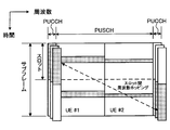
上りリンクで送信される信号は、図1に示すように、適切な無線リソースにマッピングされて移動端末装置から無線基地局装置に送信される。この場合において、ユーザデータ(UE(User Equipment)#1,UE#2)は、上りリンク共有チャネル(PUSCH:Physical Uplink Shared CHannel)に割り当てられる。また、制御情報は、ユーザデータと同時に送信する場合はPUSCHと時間多重され、制御情報のみを送信する場合は、上りリンク制御チャネル(PUCCH:Physical Uplink Control CHannel)に割り当てられる。この上りリンクで送信される制御情報には、下りリンク共有チャネル(PDSCH::Physical Downlink Shared CHannel))信号に対する再送応答信号(ACK/NACK)などが含まれる。
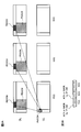
また、LTE(Rel-8)においては、PDSCH信号の再送応答信号として、ACK/NACK信号に加えて、DTX(Discontinuous Transmission)がサポートされている。DTXは、「ACKもNACKも移動端末装置から通知されなかった」という判定結果であり、これは移動端末装置が下りリンク制御チャネル(PDCCH:Physical Downlink Control CHannel)信号を受信できなかったことを意味する(図2参照)。この場合、移動端末装置は、自局宛にPDSCH信号が送信されたことを検知しないため、結果としてACKもNACKも送信しない(何も送信しない)ことになる。無線基地局装置は、ACKを受信すると次の新規データを送信するが、NACKや、応答がないDTX状態の場合は、送信したデータの再送信を行うように再送制御を行う。
また、DTXは、PDCCH信号の送信電力制御等への適用が検討されている。例えば、無線基地局装置から移動端末装置に送信したPDSCH信号に対して、ACK又はNACKが通知された場合には、PDCCH信号の送信電力が十分であると判断し、DTXが通知された(ACKもNACKも通知されない)場合には、PDCCH信号の送信電力が不十分であると判断して、PDCCH信号の送信電力を制御することが検討されている。具体的には、PDCCH信号のアウターループ制御において、ACK又はNACKが通知された場合にPDCCH信号の送信電力制御に用いるオフセット値ΔDL,iを下げ、DTXが通知された場合にPDCCH信号の送信電力制御に用いるオフセット値ΔDL,iを上げることにより、PDCCH信号の送信電力制御に用いるオフセット値を適切に制御することが可能となる。
3GPP, TR25.912 (V7.1.0), "Feasibility study for Evolved UTRA and UTRAN", Sept. 2006
ところで、3GPPにおいては、更なる広帯域化及び高速化を目的として、LTEの後継のシステム(例えば、LTE-Advanced(LTE-A)システム)も検討されている。
LTE-Aシステムでは、更なる周波数利用効率及びピークスループットなどの向上を目標とし、LTEよりも広帯域な周波数の割当てが検討されている。例えば、LTE-A(Rel-10)では、LTEとの後方互換性(Backward compatibility)を持つことが一つの要求条件となっており、LTEが使用可能な帯域幅を有する基本周波数ブロック(コンポーネントキャリア(CC:Component Carrier))を複数有する送信帯域のシステム構成を採用している。
このため、複数の下りCCで送信したPDSCH信号に対する再送制御情報は、単純にはCC数倍に増大することとなる。また、これらに加えて、マルチセル協調送受信技術やLTEよりも多い送受信アンテナを用いたMIMO(Multiple Input Multiple Output)技術などのLTE-A特有の技術が検討されており、これらを制御するための再送制御情報の増大も考えられる。したがって、再送応答情報の情報量が多くなった場合であっても、再送応答情報を適用したPDCCH信号の送信電力制御を適切に行える構成について検討が必要となる。
本発明はかかる点に鑑みてなされたものであり、複数の基本周波数ブロックで構成されるシステム帯域を有する通信システムにおいて、送信電力制御を適切に行うことができる無線基地局装置、移動端末装置及び送信電力制御方法を提供することを目的の一とする。
本発明の無線基地局装置の一は、複数の基本周波数ブロックを含むシステム帯域で移動端末装置と無線通信を行う無線基地局装置であって、前記移動端末装置に対して前記複数の基本周波数ブロック毎に下りリンク制御チャネル信号を送信する送信部と、前記移動端末装置から所定の基本周波数ブロックに集約して通知される再送応答信号を受信する受信部と、を有し、前記送信部は、所定の期間に前記送信部から送信された前記下りリンク制御チャネル信号の送信回数Nと、前記所定の期間に送信された前記下りリンク制御チャネル信号に付随する下りリンク共有チャネル信号に対して前記移動端末装置から通知された所定の再送応答信号の送信回数に関する情報とに基づいて、下りリンク制御チャネル信号の送信電力を制御する送信電力制御部を有することを特徴とする。
この構成によれば、複数の基本周波数ブロックを有するシステム帯域において、各基本周波数ブロックで送信されたPDSCH信号に対する再送応答信号が所定の基本周波数ブロックに集約して送信される場合であっても、再送応答信号の送信回数を特定して、下りリンク制御チャネル信号の送信電力制御を適切に制御することが可能となる。
本発明の移動端末装置の一は、前記無線基地局装置から前記複数の基本周波数ブロック毎に通知される下りリンク制御チャネル信号を受信し、所定の期間に通知された前記下りリンク共有チャネル信号に対する所定の再送応答信号の送信回数に関する情報を検出する受信部と、前記下りリンク制御チャネル信号に付随した下りリンク共有チャネル信号に対する再送応答信号を所定の基本周波数ブロックに集約して前記無線基地局装置に送信すると共に、前記下りリンク共有チャネル信号に対する所定の再送応答信号の送信回数に関する情報を前記無線基地局装置に通知する送信部を有することを特徴とする。
本発明の送信電力制御方法の一は、複数の基本周波数ブロックを含むシステム帯域で無線通信を行う無線基地局装置の下りリンク制御チャネル信号の送信電力を制御する送信電力制御方法であって、前記無線基地局装置から移動端末装置に対して、前記複数の基本周波数ブロック毎に下りリンク制御チャネル信号を送信するステップと、前記移動端末装置が、前記複数の基本周波数ブロック毎に前記下りリンク制御チャネル信号を受信し、前記下りリンク制御チャネル信号に付随した下りリンク共有チャネル信号に対する再送応答信号を所定の基本周波数ブロックに集約して前記無線基地局装置に送信するステップと、前記移動端末装置が、所定の期間に通知された前記下りリンク共有チャネル信号に対する所定の再送応答信号の送信回数に関する情報を前記無線基地局装置に通知するステップと、前記無線基地局装置が、前記所定の期間に送信した前記下りリンク制御チャネル信号の送信回数Nと、前記移動端末装置から通知された所定の再送応答信号の送信回数に関する情報とに基づいて、下りリンク制御チャネル信号の送信電力を制御するステップと、を有することを特徴とする。
本発明によれば、複数の基本周波数ブロックで構成されるシステム帯域を有する通信システムにおいて、送信電力制御を適切に行うことが可能となる。
上述したように、下りリンク共有チャネル(PDSCH)の信号に対しては、そのフィードバック制御情報である再送応答信号(ACK/NACK)が上りリンク制御チャネル(PUCCH)に割当てて送信される。再送応答信号は、送信信号が適切に受信されたことを示す肯定応答(ACK:Acknowledgement)、それが適切に受信されなかったことを示す否定応答(NACK:Negative Acknowledgement)、又はACKもNACKも移動端末装置から通知されなかったことを示すDTXで表現される(図2参照)。
無線基地局装置は、肯定応答(ACK)によりPDSCHの送信成功を、否定応答(NACK)によりPDSCHに誤りが検出されたことを検知することができる。また、無線基地局装置は、上りリンクにおいて再送応答信号に割り当てた無線リソースでの受信電力が所定値以下である場合にDTXであると判定することができる。
また、上述したように、再送応答信号の内容に基づいて、PDCCH信号の送信電力制御を行うことが検討されている。以下に、ACK/NACK/DTXを用いたPDCCH信号のアウターループ制御の一例について説明する。
無線基地局装置は、移動端末装置に対して送信したPDSCH信号に対する再送応答信号を受信すると、当該再送応答信号の内容に基づいて、下記の式(5)を用いてPDCCH信号の送信電力制御に用いるオフセット値を制御する。

上記式(5)において、Δ’DL,iは任意のCCiにおける時刻t+ΔTのオフセット値、ΔDL,iは任意のCCiにおける時刻tのオフセット値、Δadjは当該再送応答信号を用いてオフセットを制御するために用いる調整用オフセット値、BLERDL,targetはブロック誤り率(Block Error Rate)である。
PDSCH信号に対して、移動端末装置からACK又はNACKが通知された場合には、移動端末装置がPDCCH信号を正しく受信できていることを意味する。そのため、PDCCH信号の送信電力が十分であると判断し、オフセット値ΔDL,iを下げる動作を行う。一方で、移動端末装置に対して送信したPDSCH信号に対して、DTXが通知された場合には、移動端末装置がPDCCH信号を検知できていないことを意味する。そのため、PDCCH信号の送信電力が不十分であると判断し、オフセット値ΔDL,iを上げる動作を行う。
このように、移動端末装置から再送応答信号が通知された際に、当該再生応答信号の内容に応じて所定のタイミングでPDCCH信号の送信電力制御に用いるオフセット値を制御することにより、送信電力制御を適切に行うことができる。
ところで、上述したように、LTE-Aシステムでは、使用可能な帯域幅を有する基本周波数ブロック(CC)を複数有するシステム帯域を採用している。LTE-Aシステムの下りリンクにおいては、無線基地局装置が複数の基本周波数ブロック(CC)を選択して周波数帯域を構成し、各CCを用いてPDCCH信号等の情報を移動端末装置に対して通知する。このように、複数のCCでシステム帯域を広帯域化することをキャリアアグリゲーションという。
また、LTE-Aシステムの上りリンクにおいては、無線アクセス方式として、SC-FDMAの適用が検討されている。このため、複数の下りCCで送信されたPDSCH信号に対する再送応答信号においても、上りシングルキャリア送信の特性を維持するために所定のCCのみから送信することが検討されている。具体的には、移動端末装置において、無線基地局装置から受信した複数のCC毎のPDSCHに基づいて、各CCの再送応答信号を生成し、ユーザ特有(UE-specific)のCC(PCC)の上りリンク制御チャネル(PUCCH)に集約するようにマッピングして送信することが検討されている。
しかしながら、各CCの再送応答信号に関する情報を所定のCCに集約してマッピングする場合、再送応答信号の割当てビット数を低減する観点から、各CCの再送応答信号について個別のDTXの通知がサポートされないおそれがある。例えば、図3Aに示すように、3つのCCから構成される周波数帯域において、各CCが2コードワード伝送を行う場合に、各CCの2つの再送応答信号の内容を6ビットで表現すると(図3B参照)、各CCについて個別のDTXの通知はサポートされないこととなる。
この場合には、「全てのCCのPDCCHが受信できない場合」又は「所定のCC(PCC)のみにPDSCHの割当てがある場合」に関してDTXの通知を行うことが可能となる。しかし、複数のCCに対してPDSCH信号の割当てがあり、1つ又は2つのCCにおいてPDCCH信号が正しく受信できない場合には、ビット情報に基づいてDTXを判定することは困難となる。その結果、再送応答信号の内容に応じてPDCCH信号の送信電力を適切に制御することが困難となってしまう。
本発明者は、上記問題に鑑み、キャリアアグリゲーションにおいて、各CCのPDSCH信号に対する再送応答信号を所定のCCに集約して無線基地局装置に通知する場合であっても、再送応答信号の内容に基づいて送信電力制御を適切に行う方法を検討した結果、本願発明に至った。具体的には、所定の期間に無線基地局装置から送信されたPDCCH信号の送信回数Nと、所定の期間に送信されたPDCCH信号に付随するPDSCH信号に対して移動端末装置から通知された所定の再送応答信号の送信回数に関する情報とに基づいて、再送応答信号の内容を特定することを着想した。
また、第1の態様として、移動端末装置が送信したACK及びNACKの送信回数M1(移動端末装置が受信したPDCCH信号の受信回数)を無線基地局装置に通知することにより、PDCCH信号の送信回数Nと比較してDTXの通知回数を特定して、PDCCH信号の送信電力のオフセット値を適切に補正することを着想した。
また、第2の態様として、再送応答信号を受信した際に、NACKをDTXと仮定して、オフセット値ΔDL,iを上げる送信電力制御動作を行うと共に、移動端末装置が送信したNACKの送信回数M2を無線基地局装置に通知することにより、NACKの通知回数を検出して、PDCCH信号の送信電力のオフセット値を適切に補正することを着想した。
以下、本発明の実施の形態について詳細に説明する。なお、本実施の形態においては、本発明をLTE-Aに適用した例について説明するが、本発明はLTE-Aに適用した場合に限定されるものではない。
本実施の形態で示すPDCCH信号の送信電力制御は、無線基地局装置が所定の期間に送信したPDCCH信号に対して、移動端末装置が当該PDCCHに付随するPDSCH信号に対して送信を行った再送応答信号の送信回数に関する情報に基づいて、再送応答信号の内容を特定し、PDCCH信号の送信電力のオフセット値を適切に補正する。以下に、所定の再送応答信号の送信回数関する情報を、移動端末装置が送信したACK及びNACKの送信回数M1とする第1の送信電力制御と、移動端末装置が送信したNACKの送信回数M2とする第2の送信電力制御について説明する。
(第1の送信電力制御)
第1の送信電力制御は、無線基地局装置が所定の期間に送信したPDCCH信号に対して、移動端末装置が送信を行った再送応答信号の送信回数に関する情報に基づいて、再送応答信号の内容を特定し、PDCCH信号の送信電力のオフセット値を適切に補正する。
第1の送信電力制御は、無線基地局装置が所定の期間に送信したPDCCH信号に対して、移動端末装置が送信を行った再送応答信号の送信回数に関する情報に基づいて、再送応答信号の内容を特定し、PDCCH信号の送信電力のオフセット値を適切に補正する。
具体的には、所定の再送応答信号の送信回数に関する情報として、移動端末装置が送信したACK及びNACKの送信回数M1を用い、送信回数M1と、無線基地局装置が所定の期間に送信したPDCCH信号の送信回数Nに基づいて、移動端末装置がPDCCH信号を受信できなかった回数(N-M1)を検出する。そして、以下の式(1)を用いてPDCCH信号の送信電力のオフセット値を補正する。なお、ACK及びNACKの送信回数M1は、無線基地局装置が所定の期間に送信したPDCCH信号に対して、移動端末装置が受信したPDCCH信号の受信回数M1に相当する。

上記式(1)において、Δ’DL,iは任意のCCiにおける時刻t+ΔTのオフセット値、ΔDL,iは任意のCCiにおける時刻tのオフセット値、Δadjは当該再送応答信号を用いてオフセットを制御するために用いる調整用オフセット値、BLERDL,targetはブロック誤り率(Block Error Rate)である。
移動端末装置から無線基地局装置に通知されるPDCCH信号の受信回数M1は上位レイヤ信号を用いて通知する構成とすることができる。例えば、所定のCC(PCC)のPUSCHに割当てて無線基地局装置に通知することができる。
所定の期間としては、通信環境やPDCCH信号の送信電力制御に求められる精度等に応じて適宜変更して設定すればよい。例えば、radio frameの整数倍とすることができる。この場合、既存のシステムでは、radio frame単位で制御を行なっているため,本実施の形態に係る送信電力制御を既存システムに容易に導入できるという利点を奏する。
以下に、第1の送信電力制御の動作の一例を説明する。
まず、無線基地局装置から移動端末装置に対して、複数の基本周波数ブロックにそれぞれ対応するPDCCHに情報がマッピングされて送信される。PDCCHは、PDSCH及びPUSCHのスケジューリング情報と変調法やチャネル符号化率等のフォーマット情報を示す制御チャネルである。
移動端末装置は、複数の基本周波数ブロックに対応するPDCCH信号を受信した後、当該PDCCH信号に付随するPDSCH信号に対する再送応答信号を所定の基本周波数ブロック(PCC)に集約して無線基地局装置に送信する。また、移動端末装置は、所定の期間に受信したPDCCH信号の受信回数M1を検出し、上位レイヤ信号を用いて無線基地局装置に通知する。
無線基地局装置は、移動端末装置から通知された所定の期間に受信したPDCCH信号の受信回数M1と、移動端末装置に対して所定の期間に送信したPDCCH信号の送信回数Nとに基づいて、上記式(1)を用いてPDCCH信号の送信電力制御に用いるオフセット値を補正する。
これにより、移動端末装置から各基本周波数ブロックで送信されたPDSCH信号に対する再送応答信号を所定の基本周波数ブロックに集約して送信する場合であっても、移動端末装置から通知された送信回数M1に基づいて、再送応答信号(DTXの通知回数)を特定することができる。その結果、ACK/NACK/DTXに応じてPDCCH信号の送信電力制御を行う場合であっても、適切に行うことが可能となる。
なお、上述した第1の送信電力制御は、各CC単位で行うことも可能である。この場合、所定の期間に各CCで受信したPDCCH信号の受信回数M1を無線基地局装置に通知し、無線基地局装置において、各CCに対応する受信回数M1に基づいて、各CCにおけるPDCCH信号の送信電力のオフセット値を補正すればよい。
(第2の送信電力制御)
第2の送信電力制御は、所定のCCに集約された再送応答信号を受信した際に、NACKをDTXと仮定して、PDCCH信号の送信電力のオフセット値を制御すると共に、移動端末装置が所定の期間に送信を行ったNACKの送信回数M2に関する情報に基づいて、PDCCH信号の送信電力のオフセット値を適切に補正する。
第2の送信電力制御は、所定のCCに集約された再送応答信号を受信した際に、NACKをDTXと仮定して、PDCCH信号の送信電力のオフセット値を制御すると共に、移動端末装置が所定の期間に送信を行ったNACKの送信回数M2に関する情報に基づいて、PDCCH信号の送信電力のオフセット値を適切に補正する。
具体的に、無線基地局装置は、移動端末装置から通知される再送応答信号を受信した際に、再送応答信号の内容に基づいて、以下の式(2)を用いてPDCCH信号の送信電力のオフセット値を制御する第1の電力制御動作を行う。また、無線基地局装置は、第1の電力制御動作に加えて、NACKの送信回数M2に基づいて、以下の式(3)を用いてPDCCH信号の送信電力のオフセット値を補正する第2の電力制御動作を行う。


上記式(2)、(3)において、Δ’DL,iは任意のCCiにおける時刻t+ΔTのオフセット値、ΔDL,iは任意のCCiにおける時刻tのオフセット値、Δadjは再送応答信号を用いてオフセットを制御するために用いる調整用オフセット値、BLERDL,targetはブロック誤り率(Block Error Rate)である。
つまり、上記送信電力制御では、移動端末装置から再送応答信号が通知されるタイミングでNACKをDTXと仮定して、PDCCH信号の送信電力のオフセット値を制御する(第1の電力制御動作)。この場合には、本来オフセット値を下げるNACK信号を、オフセット値を上げるDTXと仮定しているため、PDCCHの送信電力が高くなり過品質となっている。そのため、第2の送信電力制御においては、さらに、移動端末装置から無線基地局装置に通知されるNACKの送信回数M2に基づいて、本来下げるべきオフセット値を反映させる(第2の電力制御動作)ことにより、PDCCH信号の送信電力のオフセット値を適切に補正する。
移動端末装置から無線基地局装置に通知されるNACKの送信回数M2は上位レイヤ信号を用いて通知する構成とすることができる。例えば、所定のCC(PCC)のPUSCHに割当てて無線基地局装置に通知する。
所定の期間としては、通信環境やPDCCH信号の送信電力制御に求められる精度等に応じて適宜変更して設定すればよい。例えば、radio frameの整数倍とすることができる。
以下に、第2の送信電力制御の動作の一例を説明する。
まず、無線基地局装置から移動端末装置に対して、複数の基本周波数ブロックにそれぞれ対応するPDCCHに情報がマッピングされて送信される。
移動端末装置は、複数の基本周波数ブロックに対応するPDCCH信号を受信した後、当該PDCCH信号に付随するPDSCH信号に対する再送応答信号を所定の基本周波数ブロック(PCC)に集約して無線基地局装置に送信する。また、移動端末装置は、所定の期間に送信したNACKの送信回数M2を検出し、上位レイヤ信号を用いて無線基地局装置に通知する。
無線基地局装置は、移動端末装置から通知される再送応答信号を受信した際に、再送応答信号の内容に基づいて、上記式(2)を用いてPDCCH信号の送信電力のオフセット値を制御する(第1の電力制御動作)。また、無線基地局装置は、移動端末装置から無線基地局装置に通知されるNACKの送信回数M2に基づいて、上記式(3)を用いてPDCCH信号の送信電力のオフセット値を補正する(第2の電力制御動作)。
このように、再送応答信号を受信したタイミングで、NACKをDTXと仮定して、PDCCH信号の送信電力のオフセット値を制御する一方で、移動端末装置から無線基地局装置に通知されるNACKの送信回数M2に基づいて、本来下げるべきオフセット値を反映させる補正を行うことにより、再送応答信号(DTXの通知回数)を特定することができる。その結果、ACK/NACK/DTXに応じてPDCCH信号の送信電力を制御する場合であっても、適切に制御することができる。
(2コードワード伝送の場合)
また、上記図3に示すように、2コードワード伝送(ランク2)の場合には、各CCで送信されるPDSCHに対して、「ACK、ACK」、「ACK、NACK」、「NACK、ACK」、「NACK、NACK」、「DTX」の5つの状態が考えられる。
また、上記図3に示すように、2コードワード伝送(ランク2)の場合には、各CCで送信されるPDSCHに対して、「ACK、ACK」、「ACK、NACK」、「NACK、ACK」、「NACK、NACK」、「DTX」の5つの状態が考えられる。
コードワードは、チャネル符号化(誤り訂正符号化)の符号化単位を指しており、MIMO多重伝送適用時は1または複数コードワードの伝送を行う。LTEではシングルユーザMIMOでは最大2コードワードを用いる。2レイヤ送信の場合は、各レイヤが独立したコードワードとなり、4レイヤ送信の場合は2レイヤ毎に1コードワードとなる。
第2の送信電力制御において2コードワード伝送の場合には、各CCのPDSCHに対する2つの再送応答信号として一方がACKであれば、当該CCのPDCCH信号が移動端末装置において正しく受信できたと仮定し、オフセット値を下げる動作を行ってもよい。一方で、双方がNACKの場合はDTXと区別がつかないため、双方がNACKである場合にDTXと仮定して、オフセット値を下げる制御を行う。
また、この際、上記NACKの送信回数M2は、双方がNACKの場合にカウントする。
具体的には、各基本周波数ブロックにそれぞれ対応する2つの再送応答信号のいずれかがACKであれば、再送応答信号の内容に基づいて、上記式(2)に換えて以下の式(4)を用いてPDCCH信号の送信電力のオフセット値を制御する。また、各基本周波数ブロックにそれぞれ対応する2つの再送応答信号の双方がNACKである場合に、NACKの送信回数M2をカウントし、送信回数M2に基づいて、上記式(3)を用いてPDCCH信号の送信電力のオフセット値を補正する。

上記式(4)において、Δ’DL,iは任意のCCiにおける時刻t+ΔTのオフセット値、ΔDL,iは任意のCCiにおける時刻tのオフセット値、Δadjは再送応答信号を用いてオフセットを制御するために用いる調整用オフセット値、BLERDL,targetはブロック誤り率(Block Error Rate)である。
これにより、所定のCCに集約された再送応答信号を受信した際に、NACKをDTXと仮定する回数を低減し、PDCCH信号の送信電力のオフセット値をより効果的に制御することが可能となる。
(第2の送信電力制御の変形例)
上述したように、複数の基本周波数ブロックを有するシステム帯域において、移動端末装置から各基本周波数ブロックで送信されたPDSCH信号に対する再送応答信号を所定の基本周波数ブロックに集約して送信する場合であっても、所定のCC(PCC)のみにPDSCHの割当てがある場合に関してはDTXの通知を行うことが可能となる。つまり、PCCに対して選択的にPUCCHの送信があった場合は、上記式(5)を適用することにより、再送応答信号の内容に応じて適切にPDCCH信号の送信電力のオフセット値を制御することが可能となる。
上述したように、複数の基本周波数ブロックを有するシステム帯域において、移動端末装置から各基本周波数ブロックで送信されたPDSCH信号に対する再送応答信号を所定の基本周波数ブロックに集約して送信する場合であっても、所定のCC(PCC)のみにPDSCHの割当てがある場合に関してはDTXの通知を行うことが可能となる。つまり、PCCに対して選択的にPUCCHの送信があった場合は、上記式(5)を適用することにより、再送応答信号の内容に応じて適切にPDCCH信号の送信電力のオフセット値を制御することが可能となる。
具体的に、送信電力制御部は、複数の基本周波数ブロックの中で所定の基本周波数ブロック(PCC)を用いて選択的に送信されたPDSCH信号に対する再送応答信号を受信した際に、当該再送応答信号の内容に基づいて、上記式(5)を用いてPDCCH信号の送信電力のオフセット値を制御する。また、この際、所定の基本周波数ブロックのPDSCH信号に対応する再送応答信号がNACKである場合には、上記NACKの送信回数M2に含めない値を用いて、上記式(3)を用いてPDCCH信号の送信電力のオフセット値の補正を行う。
NACKの送信回数M2に含めない方法としては、選択的に送信されたPCCのPDSCH信号に対応するNACKについて、移動端末装置側においてカウントしないようにNACKの送信回数M2を規定し、当該規定したNACKの送信回数M2を無線基地局装置に送信する構成とすることができる。また、無線端末装置側で制御する場合には、移動端末装置側において全てのNACKについてカウントして無線端末装置にNACKの送信回数M2を通知した後、無線端末装置側において通知されたNACKの送信回数M2から、選択的に送信されたPCCのPDSCH信号に対応するNACKの数を減らす構成としてもよい。
つまり、上記第2の送信電力制御方法において、無線基地局装置が再送応答信号を受信した際には、送信状況に応じて、上記式(2)、(4)、(5)を使い分けてPDCCH信号の送信電力のオフセット値を制御すると共に、上記(3)式を用いて当該オフセット値を補正する構成とすることができる。
なお、上述した第2の送信電力制御は、各CC単位で行うことも可能である。この場合、所定の期間に各CCで受信したNACKの送信回数M2を無線基地局装置に通知し、無線基地局装置において、各CCに対応する送信回数M2に基づいて、各CCにおけるPDCCH信号の送信電力のオフセット値を補正すればよい。
(移動通信システム構成)
以下、本発明に係る通信制御方法が適用される移動端末装置及び無線基地局装置等の構成について説明する。ここでは、LTE-A方式のシステム(LTE-Aシステム)に対応する無線基地局装置及び移動端末装置を用いる場合について説明する。
以下、本発明に係る通信制御方法が適用される移動端末装置及び無線基地局装置等の構成について説明する。ここでは、LTE-A方式のシステム(LTE-Aシステム)に対応する無線基地局装置及び移動端末装置を用いる場合について説明する。
まず、図4を参照しながら、本発明に係る通信制御方法が適用される移動端末装置及び無線基地局装置を有する無線通信システムについて説明する。図4は、本発明の一実施の形態に係る移動端末装置10及び無線基地局装置20を有する無線通信システム1の構成を説明するための図である。なお、図4に示す無線通信システム1は、例えば、LTEシステムが包含されるシステムである。また、この無線通信システム10は、IMT-Advancedと呼ばれても良いし、4Gと呼ばれても良い。
図4に示すように、無線通信システム1は、無線基地局装置20と、この無線基地局装置20と通信する複数の移動端末装置10(101、102、103、・・・10n、nはn>0の整数)とを含んで構成されている。無線基地局装置20は、コアネットワーク30と接続される。移動端末装置10は、セル40において無線基地局装置20と通信を行っている。なお、コアネットワーク30には、例えば、アクセスゲートウェイ装置、無線ネットワークコントローラ(RNC)、モビリティマネジメントエンティティ(MME)等が含まれるが、これに限定されるものではない。
無線通信システム10においては、無線アクセス方式として、下りリンクについてはOFDMA(直交周波数分割多元接続)が、上りリンクについてはSC-FDMA(シングルキャリア-周波数分割多元接続)又はクラスタ化DFT拡散OFDM(Clustered DFT-Spread OFDM)が適用される。
OFDMAは、周波数帯域を複数の狭い周波数帯域(サブキャリア)に分割し、各サブキャリアにデータをマッピングして通信を行うマルチキャリア伝送方式である。SC-FDMAは、システム帯域を端末毎に1つ又は連続したリソースブロックからなる帯域に分割し、複数の端末が互いに異なる帯域を用いることで、端末間の干渉を低減するシングルキャリア伝送方式である。
ここで、LTEシステムにおける通信チャネルについて説明する。下りリンクについては、各移動端末装置10で共有されるPDSCHと、下りL1/L2制御チャネル(PDCCH、PCFICH、PHICH)とが用いられる。このPDSCHにより、ユーザデータ、すなわち、通常のデータ信号が伝送される。送信データは、このユーザデータに含まれる。なお、送信識別ビットを含むULスケジューリンググラントやDLスケジューリンググラントは、L1/L2制御チャネル(PDCCH)により移動端末装置10に通知される。
上りリンクについては、各移動端末装置10で共有して使用されるPUSCHと、上りリンクの制御チャネルであるPUCCHとが用いられる。このPUSCHにより、ユーザデータが伝送される。また、PUCCHにより、下りリンクの無線品質情報(CQI:Channel Quality Indicator)等が伝送される。
次に、図5を参照して、無線基地局装置20の機能構成について説明する。図5は、無線基地局装置20の機能ブロック図の一例である。
送信部は、上りリソース割り当て情報信号生成部201と、他の下りリンクチャネル信号と、上りリソース割り当て情報信号とを多重してOFDM信号を生成するOFDM信号生成部202とを有し、移動端末装置10に対して複数の基本周波数ブロック毎にPDCCH信号を送信する。なお、図5に示す他の下りリンクチャネル信号は、データ、参照信号、制御信号などを含む。
上りリソース割り当て情報信号生成部201は、CAZAC番号、リソースマッピング情報、巡回シフト番号、ブロック拡散符号番号(OCC番号)を含む上りリソース割り当て情報信号を生成する。上りリソース割り当て情報信号生成部201は、生成した上りリソース割り当て情報信号をOFDM信号生成部202に出力する。
OFDM信号生成部202は、他の下りリンクチャネル信号及び上りリソース割り当て情報信号を含む下りリンク信号(PDCCH信号、PDSCH信号等)をサブキャリアにマッピングし、逆高速フーリエ変換(IFFT)し、CPを付加することにより、下り送信信号を生成する。このように生成された下り送信信号は、複数の基本周波数ブロック毎に下りリンクで移動端末装置10に送信される。
また、送信部は、再送応答信号に関する情報に基づいて、PDCCH信号の送信電力を制御する送信電力制御部211を有している。送信電力制御部211は、所定の期間に移動端末装置10に対して送信したPDCCH信号の送信回数Nと、所定の期間に送信されたPDCCH信号に付随するPDSCH信号に対して移動端末装置10から通知された所定の再送応答信号の送信回数に関する情報とに基づいて、PDCCH信号の送信電力を制御する。具体的には、送信電力制御部211は、上述した第1の送信電力制御又は第2の送信電力制御を適用することができる。
例えば、移動端末装置10から通知される所定の再送応答信号の送信回数に関する情報が、移動端末装置10が所定の期間にPDCCH信号を受信した受信回数M1である場合には(第1の送信電力制御)、送信電力制御部211は、送信回数M1と、送信回数Nに基づいて、上述した式(1)を用いてPDCCH信号の送信電力のオフセット値を補正して送信電力を制御する。
また、移動端末装置10から通知される所定の再送応答信号の送信回数に関する情報が、所定の再送応答信号の送信回数に関する情報が、移動端末装置10が送信したNACKの送信回数M2である場合には(第2の送信電力制御)、送信電力制御部211は、再送応答信号を受信した際に、再送応答信号の内容に基づいて、上述した式(2)を用いてPDCCH信号の送信電力のオフセット値を制御する。また、送信回数M2に基づいて、上述した式(3)を用いてPDCCH信号の送信電力のオフセット値を補正することにより送信電力制御を行う。
受信部は、受信信号からCPを除去するCP除去部203と、受信信号を高速フーリエ変換(FFT)するFFT部204と、FFT後の信号をデマッピングするサブキャリアデマッピング部205と、サブキャリアデマッピング後の信号に対してブロック拡散符号(OCC)で逆拡散するブロック逆拡散部206と、逆拡散後に信号から巡回シフトを除去して対象とするユーザの信号を分離する巡回シフト分離部207と、ユーザ分離後のデマッピング後の信号についてチャネル推定を行うチャネル推定部208と、チャネル推定値を用いてサブキャリアデマッピング後の信号をデータ復調するデータ復調部209と、データ復調後の信号をデータ復号するデータ復号部210とを有する。
CP除去部203は、CPに相当する部分を除去して有効な信号部分を抽出する。CP除去部203は、CP除去後の信号をFFT部204に出力する。FFT部204は、受信信号をFFTして周波数領域の信号に変換する。FFT部204は、FFT後の信号をサブキャリアデマッピング部205に出力する。サブキャリアデマッピング部205は、リソースマッピング情報を用いて周波数領域の信号から上り制御チャネル信号であるACK/NACK信号を抽出する。サブキャリアデマッピング部205は、抽出されたACK/NACK信号をデータ復調部209へ出力する。サブキャリアデマッピング部205は、抽出された参照信号をブロック逆拡散部206へ出力する。
ブロック逆拡散部206では、ブロック拡散、すなわち直交符号(OCC)(ブロック拡散符号)を用いて直交多重された受信信号を、移動端末装置10で用いた直交符号で逆拡散する。ブロック逆拡散部206は、逆拡散後の信号を巡回シフト分離部207へ出力する。巡回シフト分離部207は、巡回シフトを用いて直交多重された制御信号を、巡回シフト番号を用いて分離する。移動端末装置10からの上り制御チャネル信号には、ユーザ毎に異なる巡回シフト量で巡回シフトが行われている。したがって、移動端末装置10で行われた巡回シフト量と同じ巡回シフト量だけ逆方向に巡回シフトを行うことにより、受信処理の対象とするユーザの制御信号を分離することができる。巡回シフト分離部207は、ユーザ分離後の信号をチャネル推定部208に出力する。
チャネル推定部208は、巡回シフト及び直交符号を用いて直交多重された参照信号を、巡回シフト番号及び必要に応じてOCC番号を用いて分離する。チャネル推定部208においては、巡回シフト番号に対応した巡回シフト量を用いて逆方向に巡回シフトを行う。また、OCC番号に対応した直交符号を用いて逆拡散する。これにより、ユーザの信号(参照信号)を分離することが可能となる。また、チャネル推定部208は、リソースマッピング情報を用いて周波数領域の信号から受信した参照信号を抽出する。そして、CAZAC番号に対応するCAZAC符号系列と受信したCAZAC符号系列との相関をとることにより、チャネル推定を行う。
データ復調部209は、ACK/NACK信号をデータ復調し、データ復号部210に出力する。このとき、データ復調部209は、チャネル推定部208からのチャネル推定値に基づいてデータ復調する。また、データ復号部210は、復調後のACK/NACK信号をデータ復号してACK/NACK情報として出力する。
無線基地局装置20においては、ACK/NACK/DTX情報に基づいて、移動端末装置10に対する新規のPDSCHの送信、或いは、送信したPDSCHの再送を判断する。また、送信電力制御部211は、上述した第2の送信電力制御を適用する場合には、通知されたACK/NACK/DTX情報に基づいて、PDCCH信号の送信電力のオフセット値を制御する。
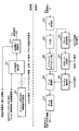
図6は、本実施の形態に係る移動端末装置10の概略構成を示す図である。図6に示す移動端末装置10は、送信部と受信部とを備えている。受信部は、無線基地局装置20から複数の基本周波数ブロック毎に通知されるPDCCH信号を受信し、所定の期間に通知されたPDCCH信号に付随するPDSCH信号に対する所定の再送応答信号の送信回数に関する情報を検出する。また、送信部は、PDCCH信号に付随したPDSCH信号に対する再送応答信号を所定の基本周波数ブロックに集約して無線基地局装置20に送信すると共に、PDSCH信号に対する所定の再送応答信号の送信回数に関する情報を無線基地局装置20に通知する。以下に、送信部と受信部の構成について具体的に説明する。
送信部は、第1ACK/NACK信号処理部100と、第2ACK/NACK信号処理部130と、参照信号処理部101と、ACK/NACK信号と参照信号とを時間多重する時間多重部102とを備えている。なお、送信部の機能ブロックにはユーザデータ(PUSCH信号)を送信する処理ブロックが図示されていないが、ユーザデータ(PUSCH)は時間多重部102にて多重される。
上記第2の送信電力の変形例で示したように、所定のCC(PCC)のPDSCHに対して選択的に割当てがあった場合は、第1ACK/NACK信号処理部100を適用し、それ以外の場合(複数のCCのPDSCHに対して割当てがあった場合)は第2ACK/NACK信号処理部130を適用することができる。また、PDSCH信号に対する所定の再送応答信号の送信回数に関する情報は、上りリンク共有チャネルに割当てて無線基地局装置20に通知することができる。
第1ACK/NACK信号処理部100は、LTE(Rel-8)システムで規定されるPUCCHフォーマット1(1a、1b)によって再送応答信号を送信する際に必要となる処理を行う部分である。例えば、上記第2の送信電力の変形例で示したように、所定のCC(PCC)のPDSCHに対して選択的に割当てがあった場合には、LTE(Rel-8)システムと同様の要領で再送応答信号を送信する際に必要となる処理を行う。
第1ACK/NACK信号処理部100は、CAZAC番号に対応するCAZAC符号系列を生成するCAZAC符号生成部1001と、ACK/NACKビット系列を誤り訂正符号化するチャネル符号化部1002と、データ変調するデータ変調部1003と、生成したCAZAC符号系列をデータ変調後の信号によりブロック変調するブロック変調部1004と、ブロック変調後の信号に対して巡回シフトを行う巡回シフト部1005と、巡回シフト後の信号にブロック拡散符号でブロック拡散する(直交符号を乗算する)ブロック拡散部1006と、ブロック拡散後の信号をサブキャリアにマッピングするサブキャリアマッピング部1007と、マッピング後の信号を逆高速フーリエ変換(IFFT)するIFFT部1008と、IFFT後の信号にCP(Cyclic Prefix)を付与するCP付与部1009とを有する。
第2ACK/NACK信号処理部130は、複数のCCからPDSCH信号が通知された場合に再送応答信号を送信する際に必要となる処理(PUCCHフォーマット3)を行う部分である。
第2ACK/NACK信号処理部130は、ACK/NACKビット系列を誤り訂正符号化するチャネル符号化部1301と、ACK/NACKビット系列をデータ変調するデータ変調部1302と、データ変調後の信号にDFT(Discrete Fourier Transform)するDFT部1303と、DFT後の信号にブロック拡散符号でブロック拡散するブロック拡散部1304と、ブロック拡散後の信号をサブキャリアにマッピングするサブキャリアマッピング部1305と、マッピング後の信号をIFFTするIFFT部1306と、IFFT後の信号にCPを付与するCP付与部1307とを有する。
参照信号処理部101は、CAZAC番号に対応するCAZAC符号系列を生成するCAZAC符号生成部1011と、CAZAC符号系列により構成される参照信号に対して巡回シフトを行う巡回シフト部1012と、巡回シフト後の信号にブロック拡散符号でブロック拡散するブロック拡散部1013と、ブロック拡散後の信号をサブキャリアにマッピングするサブキャリアマッピング部1014と、マッピング後の信号をIFFTするIFFT部1015と、IFFT後の信号にCPを付与するCP付与部1016とを有する。
なお、上りリンクの参照信号には、SRS(Surrounding RS)とRSとが含まれる。SRSは、スケジューリング(及びタイミング制御)に必要な各移動端末装置10の上りリンクチャネルの状態を無線基地局装置20にて推定するための参照信号であり、PUSCH信号、PUCCH信号とは独立に第2スロットの最終SC-FDMAシンボルに多重される。一方、RSは、各スロットの第2シンボルと第6シンボルに多重される。
移動端末装置10では、下りリンク共有チャネル(PDSCH)を用いて受信した信号に対してACK/NACKを判定し、これに対応するACK/NACKビット系列を生成する。生成されたACK/NACKビット系列は、予め定められた符号化テーブルに基づいて符号化された後、第1ACK/NACK信号処理部100又は第2ACK/NACK信号処理部130に出力される。具体的には、ACK/NACKビット系列は、PUCCHフォーマット1(1a、1b)が指定される場合には、第1ACK/NACK信号処理部100に出力され、PUCCHフォーマット3が指定される場合には、第2ACK/NACK信号処理部130に出力される。
第1ACK/NACK信号処理部100のデータ変調部1003は、チャネル符号化部1002でチャネル符号化されたACK/NACKビット系列を極座標成分の信号に変調する。データ変調部1003は、データ変調後の信号をブロック変調部1004へ出力する。CAZAC符号生成部1001は、ユーザに割り当てられているCAZAC番号に対応するCAZAC符号系列を準備する。CAZAC符号生成部1001は、生成したCAZAC符号系列をブロック変調部1004へ出力する。ブロック変調部1004は、1SC-FDMAシンボルに対応する時間ブロック毎にCAZAC符号系列を、データ変調後の制御信号でブロック変調する。ブロック変調部1004は、ブロック変調後の信号を巡回シフト部1005に出力する。
巡回シフト部1005は、時間領域の信号を所定の巡回シフト量だけ巡回シフトする。なお、巡回シフト量はユーザ毎に異なり、巡回シフト番号に対応づけられている。巡回シフト部1005は、巡回シフト後の信号をブロック拡散部1006に出力する。ブロック拡散部1006は、巡回シフト後の参照信号に直交符号(OCC:Orthogonal Cover Code)を乗算する(ブロック拡散する)。ブロック拡散部1006は、ブロック拡散後の信号をサブキャリアマッピング部1007に出力する。
サブキャリアマッピング部1007は、ブロック拡散後の信号をリソースマッピング情報に基づき、サブキャリアにマッピングする。サブキャリアマッピング部1007は、マッピングされた信号をIFFT部1008に出力する。IFFT部1008は、マッピングされた信号をIFFTして時間領域の信号に変換する。IFFT部1008は、IFFT後の信号をCP付与部1009に出力する。CP付与部1009は、マッピング後の信号にCPを付与する。CP付与部1009は、CPを付与した信号を時間多重部102に出力する。
第2ACK/NACK信号処理部130のデータ変調部1302は、チャネル符号化部1301でチャネル符号化されたACK/NACKビット系列を極座標成分の信号に変調する。データ変調部1302は、データ変調後の信号をDFT部1303へ出力する。DFT部1303は、データ変調後の信号にDFTして周波数領域の信号に変換する。DFT部1303は、DFT後の信号をブロック拡散部1304に出力する。ブロック拡散部1304は、DFT後の信号に直交符号(OCC)を乗算する。ブロック拡散部1304は、ブロック拡散後の信号をサブキャリアマッピング部1305に出力する。
サブキャリアマッピング部1305は、ブロック拡散後の信号をリソースマッピング情報に基づき、サブキャリアにマッピングする。サブキャリアマッピング部1305は、マッピングされた信号をIFFT部1306に出力する。IFFT部1306は、マッピングされた信号をIFFTして時間領域の信号に変換する。IFFT部1306は、IFFT後の信号をCP付与部1307に出力する。CP付与部1307は、マッピング後の信号にCPを付与する。CP付与部1307は、CPを付与した信号を時間多重部102に出力する。
参照信号処理部101のCAZAC符号生成部1011は、ユーザに割り当てられているCAZAC番号に対応するCAZAC符号系列を準備し、参照信号として用いる。CAZAC符号生成部1011は、参照信号を巡回シフト部1012に出力する。巡回シフト部1012は、時間領域の参照信号を所定の巡回シフト量だけシフトする。なお、巡回シフト量はユーザ毎に異なり、巡回シフト番号に対応づけられている。巡回シフト部1012は、巡回シフト後の参照信号をブロック拡散部1013に出力する。
ブロック拡散部1013は、巡回シフト後の参照信号に直交符号(OCC)を乗算する。ここで、参照信号に用いるOCC(ブロック拡散符号番号)については、上位レイヤからRRCシグナリングなどで通知しても良く、データシンボルのCS(Cyclic Shift)に予め関連付けられたOCCを用いても良い。ブロック拡散部1013は、ブロック拡散後の信号をサブキャリアマッピング部1014に出力する。
サブキャリアマッピング部1014は、周波数領域の信号をリソースマッピング情報に基づき、サブキャリアにマッピングする。サブキャリアマッピング部1014は、マッピングされた参照信号をIFFT部1015に出力する。IFFT部1015は、マッピングされた信号をIFFTして時間領域の参照信号に変換する。IFFT部1015は、IFFT後の参照信号をCP付与部1016に出力する。CP付与部1016は、直交符号乗算後の参照信号にCPを付与する。CP付与部1016は、CPを付与した参照信号を時間多重部102に出力する。
時間多重部102では、第1ACK/NACK信号処理部100又は第2ACK/NACK信号処理部130からの上り制御信号と、参照信号処理部101からの参照信号とを時間多重して、上り制御チャネル信号を含む送信信号とする。このように生成された送信信号は、上りリンクにて無線基地局装置20に送信される。
受信部は、OFDM信号を復調するOFDM信号復調部103と、下り制御信号を復号して再送応答信号のための無線リソースを判定する下り制御信号復号部104と、下りリンク信号によりACK/NACKを判定するACK/NACK判定部106と、ACK/NACK信号符号化部107とを有する。
OFDM信号復調部103は、下りOFDM信号を受信し、復調する。すなわち、下りOFDM信号からCPを除去し、高速フーリエ変換し、BCH信号或いは下り制御信号が割り当てられたサブキャリアを取り出し、データ復調する。OFDM信号復調部103は、データ復調後の信号を下り制御信号復号部104に出力する。また、OFDM信号復調部103は、下りリンク信号をACK/NACK判定部106に出力する。
下り制御信号復号部104は、データ復調後の信号を復号して、自装置に割り当てられた再送応答信号のための無線リソースを判定する。具体的には、下り制御信号復号部104は、データ復調後の信号を復号して、無線リソースとして、CAZAC番号、リソースマッピング情報、巡回シフト番号、ブロック拡散符号番号を得る。下り制御信号復号部104は、これらの無線リソースをACK/NACK判定部106に出力する。
ACK/NACK判定部106は、PDSCH信号が誤りなく受信できたか否かを判定し、PDSCHが誤りなく受信できていればACK、誤りが検出されればNACK、PDSCHが検出されなければDTXの各状態を判定結果(ACK/NACKビット系列)としてACK/NACK信号符号化部107に出力する。無線基地局装置20との通信に複数CCが割り当てられている場合は、CC毎にPDSCHが誤りなく受信できたか否かを判定する。また、ACK/NACK判定部106は、所定の期間に通知されたPDSCH信号に対する所定の再送応答信号の送信回数に関する情報を検出し、送信部を介して無線基地局装置に通知する。
ACK/NACK信号符号化部107は、ACK/NACK判定部106による判定結果(ACK/NACKビット系列)を、予め定められた符号化テーブルに基づいて符号化する。
このように、本実施の形態によれば、複数の基本周波数ブロックを有するシステム帯域において、各基本周波数ブロックで送信されたPDSCH信号に対する再送応答信号が所定の基本周波数ブロックに集約して送信される場合であっても、再送応答信号の送信回数を特定して、PDCCH信号の送信電力制御を適切に行うことが可能となる。
本発明の範囲を逸脱しない限りにおいて、上記説明における処理部の数、処理手順については適宜変更して実施することが可能である。また、図に示される要素の各々は機能を示しており、各機能ブロックがハードウエアで実現されても良く、ソフトウエアで実現されてもよい。その他、本発明の範囲を逸脱しないで適宜変更して実施することが可能である。
本出願は、2010年11月12日出願の特願2010-254096に基づく。この内容は、全てここに含めておく。
Claims (16)
- 複数の基本周波数ブロックを含むシステム帯域で移動端末装置と無線通信を行う無線基地局装置であって、
前記移動端末装置に対して前記複数の基本周波数ブロック毎に下りリンク制御チャネル信号を送信する送信部と、前記移動端末装置から所定の基本周波数ブロックに集約して通知される再送応答信号を受信する受信部と、を有し、
前記送信部は、所定の期間に前記送信部から送信された前記下りリンク制御チャネル信号の送信回数Nと、前記所定の期間に送信された前記下りリンク制御チャネル信号に付随する下りリンク共有チャネル信号に対して前記移動端末装置から通知された所定の再送応答信号の送信回数に関する情報とに基づいて、下りリンク制御チャネル信号の送信電力を制御する送信電力制御部を有することを特徴とする無線基地局装置。 - 前記所定の再送応答信号の送信回数に関する情報が、前記移動端末装置が送信したACK及びNACKの送信回数M1であり、
前記送信電力制御部は、前記送信回数M1と、前記送信回数Nに基づいて、以下の式(1)を用いて前記下りリンク制御チャネル信号の送信電力のオフセット値を補正することを特徴とする請求項1に記載の無線基地局装置。

- 前記所定の再送応答信号の送信回数に関する情報が、前記移動端末装置が送信したNACKの送信回数M2であり、
前記送信電力制御部は、前記再送応答信号を受信した際に、前記再送応答信号の内容に基づいて、以下の式(2)を用いて前記下りリンク制御チャネル信号の送信電力のオフセット値を制御すると共に、前記送信回数M2に基づいて、以下の式(3)を用いて前記下りリンク制御チャネル信号の送信電力のオフセット値を補正することを特徴とする請求項1に記載の無線基地局装置。


- 前記送信電力制御部は、2コードワード伝送の場合に、前記式(2)に換えて以下の式(4)を用いて前記下りリンク制御チャネル信号の送信電力のオフセット値を制御し、
各基本周波数ブロックにそれぞれ対応する2つの再送応答信号の双方がNACKである場合に、前記NACKの送信回数M2をカウントし、前記送信回数M2に基づいて、前記式(3)を用いて前記下りリンク制御チャネル信号の送信電力のオフセット値を補正することを特徴とする請求項3に記載の無線基地局装置。

- 前記送信電力制御部は、前記複数の基本周波数ブロックの中で前記所定の基本周波数ブロックを用いて選択的に送信された前記下りリンク共有チャネル信号に対する再送応答信号を受信した際に、前記再送応答信号の内容に基づいて、以下の式(5)を用いて前記下りリンク制御チャネル信号の送信電力のオフセット値を制御することを特徴とする請求項3又は請求項4に記載の無線基地局装置。

- 前記無線基地局装置から前記複数の基本周波数ブロック毎に通知される下りリンク制御チャネル信号を受信し、所定の期間に通知された前記下りリンク共有チャネル信号に対する所定の再送応答信号の送信回数に関する情報を検出する受信部と、
前記下りリンク制御チャネル信号に付随した下りリンク共有チャネル信号に対する再送応答信号を所定の基本周波数ブロックに集約して前記無線基地局装置に送信すると共に、前記下りリンク共有チャネル信号に対する所定の再送応答信号の送信回数に関する情報を前記無線基地局装置に通知する送信部を有することを特徴とする移動端末装置。 - 前記送信部は、前記下りリンク共有チャネル信号に対する所定の再送応答信号の送信回数に関する情報を上りリンク共有チャネルに割当てて前記無線基地局装置に通知することを特徴とする請求項6に記載の移動端末装置。
- 前記所定の再送応答信号の送信回数に関する情報が、前記送信部が送信したACK及びNACKの送信回数M1であることを特徴とする請求項7に記載の移動端末装置。
- 前記所定の再送応答信号の送信回数に関する情報が、前記送信部が送信したNACKの送信回数M2であることを特徴とする請求項7に記載の移動端末装置。
- 前記再送応答信号送信回数通知部は、2コードワード伝送の場合に、各基本周波数ブロックにそれぞれ対応する2つの再送応答信号のいずれかがACKであれば、前記NACKの送信回数M2に含めず、各基本周波数ブロックにそれぞれ対応する2つの再送応答信号の双方がNACKである場合に、前記NACKの送信回数M2に含めることを特徴とする請求項9に記載の移動端末装置。
- 前記再送応答信号送信回数通知部は、前記複数の基本周波数ブロックの中で前記所定の基本周波数ブロックを用いて選択的に送信された前記下りリンク共有チャネル信号を受信した際に、受信した前記下りリンク共有チャネル信号に対する再送応答信号がNACKである場合には、前記NACKの送信回数M2に含めないことを特徴とする請求項9又は請求項10に記載の移動端末装置。
- 複数の基本周波数ブロックを含むシステム帯域で無線通信を行う無線基地局装置の下りリンク制御チャネル信号の送信電力を制御する送信電力制御方法であって、
前記無線基地局装置から移動端末装置に対して、前記複数の基本周波数ブロック毎に下りリンク制御チャネル信号を送信するステップと、
前記移動端末装置が、前記複数の基本周波数ブロック毎に前記下りリンク制御チャネル信号を受信し、前記下りリンク制御チャネル信号に付随した下りリンク共有チャネル信号に対する再送応答信号を所定の基本周波数ブロックに集約して前記無線基地局装置に送信するステップと、
前記移動端末装置が、所定の期間に通知された前記下りリンク共有チャネル信号に対する所定の再送応答信号の送信回数に関する情報を前記無線基地局装置に通知するステップと、
前記無線基地局装置が、前記所定の期間に送信した前記下りリンク制御チャネル信号の送信回数Nと、前記移動端末装置から通知された所定の再送応答信号の送信回数に関する情報とに基づいて、下りリンク制御チャネル信号の送信電力を制御するステップと、を有することを特徴とする送信電力制御方法。 - 前記所定の再送応答信号の送信回数に関する情報が、前記移動端末装置が送信したACK及びNACKの送信回数M1であり、
前記無線基地局装置は、前記送信回数M1と、前記送信回数Nに基づいて、以下の式(1)を用いて前記下りリンク制御チャネル信号の送信電力のオフセット値を補正することを特徴とする請求項12に記載の送信電力制御方法。

- 前記所定の再送応答信号の送信回数に関する情報が、前記移動端末装置が送信したNACKの送信回数M2であり、
前記無線基地局装置は、前記再送応答信号を受信した際に、前記再送応答信号の内容に基づいて、以下の(2)を用いて前記下りリンク制御チャネル信号の送信電力のオフセット値を制御すると共に、前記送信回数M2に基づいて、以下の式(3)を用いて前記下りリンク制御チャネル信号の送信電力のオフセット値を補正することを特徴とする請求項12に記載の送信電力制御方法。


- 前記無線基地局装置は、2コードワード伝送の場合に、前記式(3)に換えて以下の式(4)を用いて前記下りリンク制御チャネル信号の送信電力のオフセット値を制御し、
各基本周波数ブロックにそれぞれ対応する2つの再送応答信号の双方がNACKである場合に、前記NACKの送信回数M2をカウントすることを特徴とする請求項14に記載の送信電力制御方法。

- 前記無線基地局装置は、前記複数の基本周波数ブロックの中で前記所定の基本周波数ブロックを用いて選択的に送信された前記下りリンク共有チャネル信号に対する再送応答信号を受信した際に、前記再送応答信号の内容に基づいて、以下の式(5)を用いて前記下りリンク制御チャネル信号の送信電力のオフセット値を制御することを特徴とする請求項14又は請求項15に記載の送信電力制御方法。

Priority Applications (2)
| Application Number | Priority Date | Filing Date | Title |
|---|---|---|---|
| CN2011800539948A CN103222317A (zh) | 2010-11-12 | 2011-10-03 | 无线基站装置、移动终端装置以及发送功率控制方法 |
| US13/884,237 US20130288738A1 (en) | 2010-11-12 | 2011-10-03 | Radio base station apparatus, mobile terminal apparatus and transmission power control method |
Applications Claiming Priority (2)
| Application Number | Priority Date | Filing Date | Title |
|---|---|---|---|
| JP2010254096A JP5388370B2 (ja) | 2010-11-12 | 2010-11-12 | 無線基地局装置、移動端末装置及び送信電力制御方法 |
| JP2010-254096 | 2010-11-12 |
Publications (1)
| Publication Number | Publication Date |
|---|---|
| WO2012063575A1 true WO2012063575A1 (ja) | 2012-05-18 |
Family
ID=46050729
Family Applications (1)
| Application Number | Title | Priority Date | Filing Date |
|---|---|---|---|
| PCT/JP2011/072760 Ceased WO2012063575A1 (ja) | 2010-11-12 | 2011-10-03 | 無線基地局装置、移動端末装置及び送信電力制御方法 |
Country Status (4)
| Country | Link |
|---|---|
| US (1) | US20130288738A1 (ja) |
| JP (1) | JP5388370B2 (ja) |
| CN (1) | CN103222317A (ja) |
| WO (1) | WO2012063575A1 (ja) |
Families Citing this family (13)
| Publication number | Priority date | Publication date | Assignee | Title |
|---|---|---|---|---|
| US9432159B2 (en) * | 2011-12-21 | 2016-08-30 | Nokia Solutions And Networks Oy | Method, apparatus and computer program for providing sounding reference signals for coordinated multipoint transmissions |
| WO2016003335A1 (en) * | 2014-07-02 | 2016-01-07 | Telefonaktiebolaget L M Ericsson (Publ) | Method and network node for calibrating uplink measurements to offset beamforming of neighbouring nodes |
| US10492192B2 (en) * | 2015-04-21 | 2019-11-26 | Telefonaktiebolaget L M Ericsson (Publ) | PDCCH link adaptation in carrier aggregation |
| TWI803947B (zh) | 2015-11-04 | 2023-06-01 | 美商內數位專利控股公司 | 無線傳輸/接收單元及由其實施的方法 |
| US20170134139A1 (en) * | 2015-11-06 | 2017-05-11 | Electronics And Telecommunications Research Institute | Method and apparatus for fast access in communication system |
| EP3402257B1 (en) * | 2016-01-07 | 2025-09-03 | Panasonic Intellectual Property Management Co., Ltd. | Communication device and communication method |
| US10356764B2 (en) * | 2016-09-30 | 2019-07-16 | Qualcomm Incorporated | Channelization for uplink transmissions |
| US10225826B2 (en) * | 2017-03-24 | 2019-03-05 | Nokia Technologies Oy | Transmission of uplink control information for multiple control channel format lengths |
| WO2018198351A1 (ja) * | 2017-04-28 | 2018-11-01 | 富士通株式会社 | 端末装置、基地局装置、無線通信システム及び端末装置制御方法 |
| EP4557648A3 (en) | 2017-05-03 | 2025-09-03 | InterDigital Patent Holdings, Inc. | Methods, systems, and apparatus for transmitting uplink control information |
| CN108931615B (zh) * | 2018-08-10 | 2020-12-01 | 河北宙清环保科技有限公司 | 基于移动检测装置的空气污染监测方法及监测系统 |
| EP3846570B1 (en) * | 2018-09-27 | 2023-03-22 | LG Electronics Inc. | Feedback monitoring in a narrowband wireless communication system |
| JP7395379B2 (ja) | 2020-02-07 | 2023-12-11 | キヤノン株式会社 | 通信装置、制御方法、およびプログラム |
Family Cites Families (6)
| Publication number | Priority date | Publication date | Assignee | Title |
|---|---|---|---|---|
| WO2003092213A1 (en) * | 2002-04-24 | 2003-11-06 | Samsung Electronics Co., Ltd. | Apparatus and method for supporting automatic repeat request in a high-speed wireless packet data communication system |
| CN101455114B (zh) * | 2006-05-24 | 2011-10-05 | 日本电气株式会社 | 移动通信系统、基站和用于它们的发射功率控制方法 |
| CN102119503B (zh) * | 2008-05-15 | 2014-04-02 | 爱立信电话股份有限公司 | 增大混合自动重复请求协议的可靠性 |
| KR101667826B1 (ko) * | 2008-11-04 | 2016-10-19 | 애플 인크. | 제 1 캐리어에서 제 2, 다른 캐리어에서의 제어 정보를 표시하기 위해 다운링크 제어 구조를 제공하는 방법 |
| JP4792513B2 (ja) * | 2009-04-27 | 2011-10-12 | 株式会社エヌ・ティ・ティ・ドコモ | 無線通信システムで使用される方法及び通信端末 |
| US8804586B2 (en) * | 2010-01-11 | 2014-08-12 | Blackberry Limited | Control channel interference management and extended PDCCH for heterogeneous network |
-
2010
- 2010-11-12 JP JP2010254096A patent/JP5388370B2/ja not_active Expired - Fee Related
-
2011
- 2011-10-03 CN CN2011800539948A patent/CN103222317A/zh active Pending
- 2011-10-03 WO PCT/JP2011/072760 patent/WO2012063575A1/ja not_active Ceased
- 2011-10-03 US US13/884,237 patent/US20130288738A1/en not_active Abandoned
Non-Patent Citations (2)
| Title |
|---|
| ALCATEL-LUCENT: "A/N resource allocation for PUCCH", 3GPP TSG- RAN WG1 #60, R1-100918, 26 February 2010 (2010-02-26) * |
| LG ELECTRONICS: "Basic approaches on UL ACK/ NACK PUCCH design in LTE-Advanced", 3GPP TSG RAN WG1 #60, R1-101348, 26 February 2010 (2010-02-26) * |
Also Published As
| Publication number | Publication date |
|---|---|
| JP5388370B2 (ja) | 2014-01-15 |
| JP2012105214A (ja) | 2012-05-31 |
| CN103222317A (zh) | 2013-07-24 |
| US20130288738A1 (en) | 2013-10-31 |
Similar Documents
| Publication | Publication Date | Title |
|---|---|---|
| JP5388370B2 (ja) | 無線基地局装置、移動端末装置及び送信電力制御方法 | |
| JP5097279B2 (ja) | 無線基地局装置、無線通信方法及び無線通信システム | |
| JP4988923B2 (ja) | 移動通信システムにおけるリソース割り当て装置及び方法 | |
| JP6027368B2 (ja) | ユーザ端末、無線通信方法及び無線通信システム | |
| JP5932554B2 (ja) | 無線通信方法、無線通信システム、無線基地局及びユーザ端末 | |
| US9232507B2 (en) | Radio base station apparatus and control information detection method | |
| EP2487978A1 (en) | Wireless communication control method, mobile terminal device and base station device | |
| US20130114501A1 (en) | Mobile terminal apparatus and radio communication method | |
| CA2867306A1 (en) | Radio communication system, radio base station apparatus, user terminal and radio resource allocation method | |
| WO2013168775A1 (ja) | ユーザ端末、無線通信方法及び無線通信システム | |
| JP6521380B2 (ja) | 端末装置、基地局装置、および無線通信方法 | |
| US9036592B2 (en) | User terminal, radio base station apparatus and radio communication method | |
| US20130279440A1 (en) | Mobile terminal apparatus and communication control method | |
| CN103155471B (zh) | 移动终端装置以及无线通信方法 | |
| JP5478645B2 (ja) | 無線通信システム |
Legal Events
| Date | Code | Title | Description |
|---|---|---|---|
| 121 | Ep: the epo has been informed by wipo that ep was designated in this application |
Ref document number: 11840555 Country of ref document: EP Kind code of ref document: A1 |
|
| NENP | Non-entry into the national phase |
Ref country code: DE |
|
| WWE | Wipo information: entry into national phase |
Ref document number: 13884237 Country of ref document: US |
|
| 122 | Ep: pct application non-entry in european phase |
Ref document number: 11840555 Country of ref document: EP Kind code of ref document: A1 |