WO2012062883A2 - A cooling device comprising a height adjustable shelf - Google Patents
A cooling device comprising a height adjustable shelf Download PDFInfo
- Publication number
- WO2012062883A2 WO2012062883A2 PCT/EP2011/069887 EP2011069887W WO2012062883A2 WO 2012062883 A2 WO2012062883 A2 WO 2012062883A2 EP 2011069887 W EP2011069887 W EP 2011069887W WO 2012062883 A2 WO2012062883 A2 WO 2012062883A2
- Authority
- WO
- WIPO (PCT)
- Prior art keywords
- shelf
- channel
- guide
- cooling device
- pin
- Prior art date
Links
Images


Classifications
-
- F—MECHANICAL ENGINEERING; LIGHTING; HEATING; WEAPONS; BLASTING
- F25—REFRIGERATION OR COOLING; COMBINED HEATING AND REFRIGERATION SYSTEMS; HEAT PUMP SYSTEMS; MANUFACTURE OR STORAGE OF ICE; LIQUEFACTION SOLIDIFICATION OF GASES
- F25D—REFRIGERATORS; COLD ROOMS; ICE-BOXES; COOLING OR FREEZING APPARATUS NOT OTHERWISE PROVIDED FOR
- F25D23/00—General constructional features
- F25D23/02—Doors; Covers
- F25D23/04—Doors; Covers with special compartments, e.g. butter conditioners
-
- F—MECHANICAL ENGINEERING; LIGHTING; HEATING; WEAPONS; BLASTING
- F25—REFRIGERATION OR COOLING; COMBINED HEATING AND REFRIGERATION SYSTEMS; HEAT PUMP SYSTEMS; MANUFACTURE OR STORAGE OF ICE; LIQUEFACTION SOLIDIFICATION OF GASES
- F25D—REFRIGERATORS; COLD ROOMS; ICE-BOXES; COOLING OR FREEZING APPARATUS NOT OTHERWISE PROVIDED FOR
- F25D25/00—Charging, supporting, and discharging the articles to be cooled
- F25D25/04—Charging, supporting, and discharging the articles to be cooled by conveyors
Definitions
- the present invention relates to a cooling device comprising a height adjustable shelf.
- a refrigerator having a stepped channel formed by inclined steps, a guide that can move in the channel and that is mounted on the shelf in an angular way, and a shelf the position of which in the body is changed by moving the guide up and down in the channel
- a refrigerator which comprises two shelf supporting members formed at both side walls of the body, at least two housings disposed curvedly to each other on the shelf supporting member, at least one inclined fixing member disposed on the shelf and provides the shelf to be mounted on the shelf supporting member by being seated in the housings.
- the position of the shelf inside the body is changed by changing the position of the fixing members.
- the aim of the present invention is the realization of a cooling device which comprises a shelf disposed on the door and the position of which can be changed by being moved in the vertical direction.
- the cooling device realized in order to attain the aim of the present invention, explicated in the first claim and the respective claims thereof, comprises two flanges situated at two sides of the door, extending towards inside the body, a channel disposed on the flange, at least two parallelogram shaped guides, disposed at the outer surfaces of the shelf side walls, borne inside the channel, providing the position of the shelf to be changed in the vertical plane by moving inside the channel and at least one locking element providing the shelf to be fixed at the position it is changed to in the vertical plane by locking.
- the guide remains in the channel both in the carrying position of the shelf wherein foodstuffs are loaded thereon to be carried and in the movable position wherein the shelf is moved by being slid in the vertical plane.
- the position of the shelf in the vertical plane is changed by sliding the guide upwards/downwards in the channel.
- the shelf In the movable position, the shelf is provided to move freely in the channel and to remain immovable in the carrying position as the guide gets stuck in the channel by means of the guide configuration.
- the configuration of the guide limits rotation amount of the shelf in the movable position, providing the movement of the shelf to be more controllable.
- the diamond shaped guide is preferably produced with the inner angles not being equal to each other.
- the shelf remains in the carrying position when the two diagonal sides of the guide bear against inner side walls of the channel In the movable position wherein the position of the shelf is changed in the vertical plane by being rotated, one side of the guide at the most bears against one inner wall of the channel.
- the guide which rotates together with the shelf, is provided to rotate inside the channel by rotating the shelf towards inside the door plane in the carrying position.
- the guide is provided to get stuck inside the channel and the shelf to remain immovable since the sides of the guide exert pressure on both inner walls of the channel in the carrying position.
- the length of the diagonal that connects the sides of the guide bearing against inner walls of the channel is almost equal to the width of the channel. In this position, the guide gets stuck inside the channel and prevents the shelf from moving in the vertical plane.
- the shelf is changed to the movable position, at least one end of the diagonal does not contact the inner side walls of the channel and the guide can move inside the channel since the guide shifts to the inclined position.
- the shelf While the shelf is changed from the carrying position to the horizontal position, the shelf rotates in the vertical axis as much as the inner acute angle of the guide at the most.
- the acute inner angle of the guide is determined as the smallest angle possible that provides the foodstuffs in the shelf not to overturn or spill when the shelf is turned for changing position.
- the position of the shelf can be changed easily when loaded without the objects therein overturning.
- the length of the diagonal connecting sides of the guide not contacting the inner walls of the channel is determined so as to provide both sides of the shelf to move simultaneously and parallel to each other when the shelf is changed to the movable position. Consequently, the shelf is provided to be moved upwards/downwards in a balanced manner without tilting with respect to the plane of the door.
- the locking element comprises more than one housing disposed at the front of the channel so as to be parallel to the channel and arranged one on top of the other and at least two pins, disposed on opposite sides of the shelf, providing the shelf to be fixed in the vertical position that it is changed to by being seated into one of the housings.
- the pin is seated in the housing at a certain height in the carrying position of the shelf and moves freely together with the shelf by dislodging from the housing in the movable position of the shelf.
- the pin is provided to dislodge from the housing into which it is seated and provided to be seated into another housing at a different height.
- the guide is prevented from sliding in the channel due to the effect of the weight of the foodstuffs placed into the shelf in the carrying position of the shelf and the foodstuffs in the shelf are carried safely.
- the horizontal distance between the guide and the pin is determined to ensure that the pin is dislodged from the housing when the shelf changes from the carrying position to the movable position. Meanwhile, since the guide changes to the inclined position by rotating in the channel, the pin also is dislodged from the housing and becomes free to move outside the housing. Thus, the pin moves outside the housing, not preventing movement of the shelf while the shelf is in the movable position.
- springs are disposed between the housing and the flange.
- the springs prevent the shelf from moving in the horizontal plane by stretching during movements of the pin inside the housing.
- the cooling device comprises more than one sliding surface, disposed between each two consecutive housings, whereon the pin moves by sliding when the shelf is in the movable position.
- the sliding surfaces are configured to be angled. The pin slides by brushing the sliding surface while the shelf moves.
- the vertical position of the shelves disposed inside the door can be easily adjusted as per the need of the user without requiring to be detached from the door.
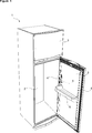
- Figure 1 – is the perspective view of a cooling device.
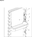
- Figure 2 – is the perspective view of a shelf when mounted on the door.
- Figure 3 – is the front view of a shelf when mounted on the door.
- Figure 4 – is the sideways view of the shelf in the carrying position.
- Figure 5 — is the sideways view of the shelf in the movable position.
- Figure 6 — is the perspective view of the flange, the channel and the housings.
- Figure 7 — is the front view of the flange, the channel and the housings.
- Figure 8 — is the perspective view of a housing.
- Figure 9 – is the sideways view of the shelf and the flange when the shelf is in carrying position.
- the cooling device (1) comprises a body (2), a door (3) providing access into the body (2), two flanges (4) disposed at two opposite sides of the door (3), extending into the body (2), a channel (5) disposed on the inner face of each flange (4) and extending in the vertical direction, one or more than one shelf (6), mounted on the door (3), having a carrying position wherein foodstuffs are loaded to be stored and a movable position, wherein the position is changed by being moved in the vertical plane ( Figure 1, Figure 2 and Figure 3).
- the cooling device (1) of the present invention furthermore, comprises:
- the shelf (6) is shaped almost as an open-top box and is mounted on the door (3) by inserting the guides (7), situated on both of the sides of the shelf (6), into the channels (5).
- the rear wall of the shelf (6) bears against the inner surface of the door (3) and the side walls thereof to the inner surface of the flanges (4) ( Figure 2 and Figure 3).
- the shelf (6) is tilted and rotated while being changed from the carrying position to the movable position.
- the shelf (6) is brought to the desired height by sliding the guides (7) inside the channels (5) in the vertical direction.
- the shelf (6) is prevented from rotating too much by means of the guide (7) configuration.
- the shelf (6) is in the movable position, at least one side of the guide (7) bears against the inner wall of the channel (5) thereby preventing the shelf (6) from rotating.
- the movement of the shelf (6) is provided to be more controllable.
- the shelf brought to the desired height by moving upwards/downwards the shelf (6) is fixed at the desired height by means of the locking element (12). Consequently, in the carrying position, the shelf (6) is provided to support the foodstuffs placed thereon in a balanced manner.
- the guide (7) When the shelf (6) is in the movable position, the guide (7), bearing against one inner side wall of the channel (5) at the most, comes to the freely movable position inside the channel (5).
- either one side of the guide (7) bears against inner side wall of the channel (5) or none of its sides bear against the inner side wall of the channel (5).
- a gap is formed between the guide (7) and the channel (5).
- the shelf (6) rotates as much as the inner acute angle of the guide (7) at the most while moving in the vertical plane.
- the guide (7) rotates around its central axis as much as its inner acute angle as the shelf (6) is rotated in the vertical plane.
- As the guide (7) rotates one of the sides of the guide (7) not contacting inside the channel (5) when the shelf (6) is in carrying position, bears against one of the inner side walls of the channel (5).
- the said channel (5) inner wall forms the friction surface for the side of the guide (7) bearing thereto and the guide (7) is provided to move slidingly upwards/downwards inside the channel (5).
- the shelf (6) can only be rotated as much as the inner acute angle of the guide (7) at the most, this acute angle is kept as small as possible during the designing of the guide (7).
- the shelf (6) is rotated in the vertical plane for changing position, the risks of the foods and beverages therein spilling etc. is eliminated by rotating it as little as possible.
- the length of the diagonal connecting the sides of the guide (7) not contacting the inner walls of the channel (5) is of the length that prevents the shelf (6) from rotating in the vertical plane while the shelf (6) is in the movable position.
- the ratio of the inner acute angle to the inner wide angle of the guide (7) is kept as small as possible.
- the locking element (12) comprises more than one housing (8) disposed on the flange (4), situated at different vertical heights and arranged parallel to the channel (5) and a pin (9) disposed on the shelf (6), seated in one of the housings (8), dislodging from the located housing (8) and seated in another housing (8) while the height of the shelf (6) is changed ( Figure 9).
- the housings (8) are situated in front of the channel (5) with respect to the plane of the door (3).
- the guide (7) When the shelf (6) is in the carrying position, the guide (7) is seated into the channel (5) and the pin (9) into the housing (8). When the shelf (6) is in the carrying position, it is in fixed position at the height wherein the housing (8) is located in the vertical plane. The shelf (6) is provided to be locked in the carrying position by means of the pin (9) being seated in the housing (8) and thus the objects placed on the shelf (6) are provided to be supported safely. When the shelf (6) is in the carrying position, the guide (7) is immovable inside the channel (5).
- the shelf (6) When the position of the shelf (6) in the vertical plane is desired to be changed, the shelf (6) is rotated inwards with respect to the plane of the door (3), in other words, counterclockwise, providing the guide (7) to rotate together with the shelf (6) ( Figure 5).
- the guide (7) becomes free to move upwards/downwards in the channel (5) by rotating inside the channel (5).
- the pin (9) seated in the housing (8) When the shelf (6) is rotated for changing height, the pin (9) seated in the housing (8) is dislodged from the housing (8) and moves freely upwards/downwards together with the shelf (6).
- the pin (9) When the shelf (6) is brought to the desired position in the vertical plane by sliding the guide (7) inside the channel (5), the pin (9) is provided to be seated in another housing (8) by rotating the shelf (6) clockwise.
- the shelf (6) When in the movable position, the shelf (6) is changed from the movable position to the carrying position by being rotated in the reverse rotational direction while changing it from the carrying position to the movable position.
- the shelf (6) is provided to be locked in the newly changed vertical position as the pin (9) is seated into the housing (8).
- the position of the shelf (6) in the vertical plane is changed, the tall objects like bottles, jars etc. are enabled to be supported on the shelf (6).
- the horizontal distance between the guide (7) and the pin (9) is determined such that the upwards/downwards movement the shelf (6) makes in the vertical plane is not prevented.
- the guide (7) is provided to shift to inclined position in the channel (5) when the shelf (6) is changed to the movable position and the pin (9) is provided to go out of the housing (8).
- the angle made by the line connecting the center of the guide (7) and the center of the pin (9) in the vertical is equal to the inner acute angle of the guide (7). Consequently, when the guide (7) becomes free to move inside the channel (5) by rotating as much as its inner acute angle in the channel (5), the pin (9) also rotates with the same angle and is released from the housing (8).
- the cooling device (1) comprises at least one spring (10), extending from the flange (4) towards the inside of the housing (8), exerting pressure on the pin (9) when the pin (9) is in the housing (8) and stretching by the motion of the pin (9) in the housing (8) ( Figure 7).
- the pin (9) is seated in the housing (8) and the spring (10) exerts pressure on the pin (9) by contacting the surface of the pin (9).
- the spring (10) preferably produced from plastic and stretching as a result of the pin (9) moving in the housing (8), prevents the shelf (6) from moving in the horizontal plane when in the carrying position.
- the shelf (6) is provided to support the foodstuffs placed therein in a more balanced manner.
- ease of tolerance is provided for the producer in the production of the shelf (6).
- the cooling device (1) comprises at least one sliding surface (11), having an inclined surface, disposed between two consecutive housings (8), providing the pin (9) to slide thereon and the movement of the shelf (6) in the vertical axis to be facilitated ( Figure 6, Figure 7 and Figure 8).
- the pin (9) is released from the housing (8) and contacts the sliding surface (11).
- the pin (9) reaches the other housing (8) wherein it will be seated, situated above or below, by sliding on the sliding surface (11).
- the sliding surface (11) facilitates the movement of the pin (9) when the shelf (6) is in the movable position and decreases the effort exerted by the user for changing the vertical position of the shelf (6).
- the guide (7) is produced by plastic injection method and integrated with the shelf (6).
- the position of the shelf (6) in the door (3) can be adjusted conveniently, without requiring to remove the foodstuffs placed on the shelf (6) which is mounted on the door (3).
- space is gained for placing the tall bottles, objects etc. into the shelf (6) and these types of objects placed into the shelf (6) are prevented from bumping to the upper shelf (6). Consequently, the tall objects are enabled to be placed on the shelf (6).
Abstract
The present invention relates to a cooling device (1) that comprises a body (2), a door (3) providing access into the body (2), two flanges (4) disposed at two opposite sides of the door (3), extending towards the inside of the body (2), at least one channel (5) disposed on the inner face of each flange (4), one or more shelf (6), mounted on the door (3), the position of which is changed by being moved in the vertical plane.
Description
The present invention relates to a cooling device comprising a height adjustable shelf.
In cooling devices, preferably in refrigerators, generally the objects like beverage cans, bottles, jars etc. are stored on the shelves located on the door. However, while the tall objects are placed on the shelf, problems are encountered such as the object hitting the upper shelf and therefore not being able to be placed on the shelf. Therefore, shelves are used the position inside the door of which can be changed. Features like not requiring to remove the foodstuffs in the shelf during changing position of the shelf, only changing the position in the vertical plane without removing the shelf from the body provide ease of use for the user.
In the state of the art Korean Patent Application No KR20040065368, a refrigerator is described having a stepped channel formed by inclined steps, a guide that can move in the channel and that is mounted on the shelf in an angular way, and a shelf the position of which in the body is changed by moving the guide up and down in the channel
In the state of the art Korean Patent Application No KR20040068783, a refrigerator is described which comprises two shelf supporting members formed at both side walls of the body, at least two housings disposed curvedly to each other on the shelf supporting member, at least one inclined fixing member disposed on the shelf and provides the shelf to be mounted on the shelf supporting member by being seated in the housings. The position of the shelf inside the body is changed by changing the position of the fixing members.
The aim of the present invention is the realization of a cooling device which comprises a shelf disposed on the door and the position of which can be changed by being moved in the vertical direction.
The cooling device realized in order to attain the aim of the present invention, explicated in the first claim and the respective claims thereof, comprises two flanges situated at two sides of the door, extending towards inside the body, a channel disposed on the flange, at least two parallelogram shaped guides, disposed at the outer surfaces of the shelf side walls, borne inside the channel, providing the position of the shelf to be changed in the vertical plane by moving inside the channel and at least one locking element providing the shelf to be fixed at the position it is changed to in the vertical plane by locking. The guide remains in the channel both in the carrying position of the shelf wherein foodstuffs are loaded thereon to be carried and in the movable position wherein the shelf is moved by being slid in the vertical plane. The position of the shelf in the vertical plane is changed by sliding the guide upwards/downwards in the channel. In the movable position, the shelf is provided to move freely in the channel and to remain immovable in the carrying position as the guide gets stuck in the channel by means of the guide configuration. The configuration of the guide limits rotation amount of the shelf in the movable position, providing the movement of the shelf to be more controllable.
In an embodiment of the present invention, the diamond shaped guide is preferably produced with the inner angles not being equal to each other. The shelf remains in the carrying position when the two diagonal sides of the guide bear against inner side walls of the channel In the movable position wherein the position of the shelf is changed in the vertical plane by being rotated, one side of the guide at the most bears against one inner wall of the channel. The guide, which rotates together with the shelf, is provided to rotate inside the channel by rotating the shelf towards inside the door plane in the carrying position. The guide is provided to get stuck inside the channel and the shelf to remain immovable since the sides of the guide exert pressure on both inner walls of the channel in the carrying position. When the shelf is in the movable position, one side of the guide at the most contacts the inner wall of the channel and the guide gets into the position of moving freely inside the channel. Thus, after rotating the shelf, the vertical position thereof on the door is adjusted by moving the guide upwards/downwards inside the channel.
When the shelf is in the carrying position, the length of the diagonal that connects the sides of the guide bearing against inner walls of the channel is almost equal to the width of the channel. In this position, the guide gets stuck inside the channel and prevents the shelf from moving in the vertical plane. When the shelf is changed to the movable position, at least one end of the diagonal does not contact the inner side walls of the channel and the guide can move inside the channel since the guide shifts to the inclined position.
While the shelf is changed from the carrying position to the horizontal position, the shelf rotates in the vertical axis as much as the inner acute angle of the guide at the most. The acute inner angle of the guide is determined as the smallest angle possible that provides the foodstuffs in the shelf not to overturn or spill when the shelf is turned for changing position. Thus, the position of the shelf can be changed easily when loaded without the objects therein overturning.
When the shelf is in the carrying position, the length of the diagonal connecting sides of the guide not contacting the inner walls of the channel is determined so as to provide both sides of the shelf to move simultaneously and parallel to each other when the shelf is changed to the movable position. Consequently, the shelf is provided to be moved upwards/downwards in a balanced manner without tilting with respect to the plane of the door.
In an embodiment of the present invention, the locking element comprises more than one housing disposed at the front of the channel so as to be parallel to the channel and arranged one on top of the other and at least two pins, disposed on opposite sides of the shelf, providing the shelf to be fixed in the vertical position that it is changed to by being seated into one of the housings. The pin is seated in the housing at a certain height in the carrying position of the shelf and moves freely together with the shelf by dislodging from the housing in the movable position of the shelf. When the position of the shelf is desired to be changed, the pin is provided to dislodge from the housing into which it is seated and provided to be seated into another housing at a different height. As the pin is seated into the housing, the guide is prevented from sliding in the channel due to the effect of the weight of the foodstuffs placed into the shelf in the carrying position of the shelf and the foodstuffs in the shelf are carried safely.
The horizontal distance between the guide and the pin is determined to ensure that the pin is dislodged from the housing when the shelf changes from the carrying position to the movable position. Meanwhile, since the guide changes to the inclined position by rotating in the channel, the pin also is dislodged from the housing and becomes free to move outside the housing. Thus, the pin moves outside the housing, not preventing movement of the shelf while the shelf is in the movable position.
In another embodiment of the present invention, springs are disposed between the housing and the flange. The springs prevent the shelf from moving in the horizontal plane by stretching during movements of the pin inside the housing.
In another embodiment of the present invention, the cooling device comprises more than one sliding surface, disposed between each two consecutive housings, whereon the pin moves by sliding when the shelf is in the movable position. The sliding surfaces are configured to be angled. The pin slides by brushing the sliding surface while the shelf moves. Thus, changing the position of the shelf in the vertical plane becomes easier, and the effort exerted by the user for changing the position of the shelf is decreased.
By means of the cooling device of the present invention, the vertical position of the shelves disposed inside the door can be easily adjusted as per the need of the user without requiring to be detached from the door.
The cooling device realized in order to attain the aim of the present invention is illustrated in the attached figures, where:
Figure 1 – is the perspective view of a cooling device.
Figure 2 – is the perspective view of a shelf when mounted on the door.
Figure 3 – is the front view of a shelf when mounted on the door.
Figure 4 – is the sideways view of the shelf in the carrying position.
Figure 5 – is the sideways view of the shelf in the movable position.
Figure 6 – is the perspective view of the flange, the channel and the housings.
Figure 7 – is the front view of the flange, the channel and the housings.
Figure 8 – is the perspective view of a housing.
Figure 9 – is the sideways view of the shelf and the flange when the shelf is in carrying position.
The elements illustrated in the figures are numbered as follows:
- Cooling device
- Body
- Door
- Flange
- Channel
- Shelf
- Guide
- Housing
- Pin
- Spring
- Sliding surface
- Locking element
The cooling device (1) comprises a body (2), a door (3) providing access into the body (2), two flanges (4) disposed at two opposite sides of the door (3), extending into the body (2), a channel (5) disposed on the inner face of each flange (4) and extending in the vertical direction, one or more than one shelf (6), mounted on the door (3), having a carrying position wherein foodstuffs are loaded to be stored and a movable position, wherein the position is changed by being moved in the vertical plane (Figure 1, Figure 2 and Figure 3).
The cooling device (1) of the present invention, furthermore, comprises:
- a parallelogram shaped guide (7), disposed on the shelf (6), borne in the channel (5), remaining inside the channel (5) both in the carrying position and the movable position of the shelf (6) and moving inside the channel (5) when the shelf (6) is in the movable position and
- a locking element (12) that provides the shelf (6) to remain in the carrying position by being fixed at different heights
(Figure 4 and Figure 5).
The shelf (6) is shaped almost as an open-top box and is mounted on the door (3) by inserting the guides (7), situated on both of the sides of the shelf (6), into the channels (5). Thus, the rear wall of the shelf (6) bears against the inner surface of the door (3) and the side walls thereof to the inner surface of the flanges (4) (Figure 2 and Figure 3).
The shelf (6) is tilted and rotated while being changed from the carrying position to the movable position. The shelf (6) is brought to the desired height by sliding the guides (7) inside the channels (5) in the vertical direction. When the shelf (6) is in the movable position, the shelf (6) is prevented from rotating too much by means of the guide (7) configuration. When the shelf (6) is in the movable position, at least one side of the guide (7) bears against the inner wall of the channel (5) thereby preventing the shelf (6) from rotating. Thus, the movement of the shelf (6) is provided to be more controllable. When the shelf brought to the desired height by moving upwards/downwards, the shelf (6) is fixed at the desired height by means of the locking element (12). Consequently, in the carrying position, the shelf (6) is provided to support the foodstuffs placed thereon in a balanced manner.
When the shelf (6) is in the carrying position, the two opposite sides of the guide (7), extending parallel to each other, bear against the opposite sides of the channel (5) and when the shelf (6) is in the movable position, one side of the guide (7) at the most bears against one side wall of the channel (5) (Figure 4 and Figure 5). When the shelf (6) is in the carrying position, the shelf (6) is prevented from moving in the vertical plane by providing the guide (7) to get stuck in the channel (5). When the shelf (6) is changed to the movable position by being rotated, the sides of the guide (7) exerting pressure on the inner walls of the channel (5) lose contact with at least one inner side wall of the channel (5) (Figure 5). When the shelf (6) is in the movable position, the guide (7), bearing against one inner side wall of the channel (5) at the most, comes to the freely movable position inside the channel (5). When the shelf (6) is in the movable position, either one side of the guide (7) bears against inner side wall of the channel (5) or none of its sides bear against the inner side wall of the channel (5). When at most one side of the guide (7) bears against one inner side wall of the channel (5), a gap is formed between the guide (7) and the channel (5). Thus, the shelf (6) is positioned at the desired height on the door (3) by moving the guide (7) upwards/downwards inside the channel (5).
When the shelf (6) is in the carrying position, the length of the diagonal connecting the sides of the guide (7) bearing against inner walls of the channel (5) is almost equal to the width of the channel (5) (Figure 4). In the carrying position of the shelf (6), when the two sides of the guide (7) extending parallel to each other bear against the inner walls of the channel (5), the diagonal connecting these two sides is almost parallel to the ground and gets stuck inside the channel (5). As this diagonal gets stuck inside the channel (5), the shelf (6) is provided to remain immovable in the carrying position. In the movable position whereto the shelf (6) is changed by being rotated, the said diagonal becomes inclined with respect to the ground and its horizontal projection becomes smaller than the width of the channel (5) (Figure 5). Thus, the movement limiting effect of the guide (7) inside the channel (5) is eliminated and the guide (7) is changed to the upwards/downwards freely movable position inside the channel (5).
The shelf (6) rotates as much as the inner acute angle of the guide (7) at the most while moving in the vertical plane. The guide (7) rotates around its central axis as much as its inner acute angle as the shelf (6) is rotated in the vertical plane. As the guide (7) rotates, one of the sides of the guide (7) not contacting inside the channel (5) when the shelf (6) is in carrying position, bears against one of the inner side walls of the channel (5). The said channel (5) inner wall forms the friction surface for the side of the guide (7) bearing thereto and the guide (7) is provided to move slidingly upwards/downwards inside the channel (5). Since the shelf (6) can only be rotated as much as the inner acute angle of the guide (7) at the most, this acute angle is kept as small as possible during the designing of the guide (7). Thus, when the shelf (6) is rotated in the vertical plane for changing position, the risks of the foods and beverages therein spilling etc. is eliminated by rotating it as little as possible.
In an embodiment of the present invention, when the shelf (6) is in the carrying position, the length of the diagonal connecting the sides of the guide (7) not contacting the inner walls of the channel (5) is of the length that prevents the shelf (6) from rotating in the vertical plane while the shelf (6) is in the movable position. In other words, the ratio of the inner acute angle to the inner wide angle of the guide (7) is kept as small as possible. Thus, when the shelf (6) is in the carrying position, the length of the diagonal connecting the sides of the guide (7) not contacting inner walls of the channel (5) is kept as long as possible and the guides (7) situated on both sides of the shelf (6) are provided to move simultaneously inside the channel (5) with respect to one another when the shelf (6) is in the movable position.
In an embodiment of the present invention, the locking element (12) comprises more than one housing (8) disposed on the flange (4), situated at different vertical heights and arranged parallel to the channel (5) and a pin (9) disposed on the shelf (6), seated in one of the housings (8), dislodging from the located housing (8) and seated in another housing (8) while the height of the shelf (6) is changed (Figure 9). The housings (8) are situated in front of the channel (5) with respect to the plane of the door (3).
When the shelf (6) is in the carrying position, the guide (7) is seated into the channel (5) and the pin (9) into the housing (8). When the shelf (6) is in the carrying position, it is in fixed position at the height wherein the housing (8) is located in the vertical plane. The shelf (6) is provided to be locked in the carrying position by means of the pin (9) being seated in the housing (8) and thus the objects placed on the shelf (6) are provided to be supported safely. When the shelf (6) is in the carrying position, the guide (7) is immovable inside the channel (5).
When the position of the shelf (6) in the vertical plane is desired to be changed, the shelf (6) is rotated inwards with respect to the plane of the door (3), in other words, counterclockwise, providing the guide (7) to rotate together with the shelf (6) (Figure 5). The guide (7) becomes free to move upwards/downwards in the channel (5) by rotating inside the channel (5). When the shelf (6) is rotated for changing height, the pin (9) seated in the housing (8) is dislodged from the housing (8) and moves freely upwards/downwards together with the shelf (6). When the shelf (6) is brought to the desired position in the vertical plane by sliding the guide (7) inside the channel (5), the pin (9) is provided to be seated in another housing (8) by rotating the shelf (6) clockwise. When in the movable position, the shelf (6) is changed from the movable position to the carrying position by being rotated in the reverse rotational direction while changing it from the carrying position to the movable position. The shelf (6) is provided to be locked in the newly changed vertical position as the pin (9) is seated into the housing (8). Thus, the position of the shelf (6) in the vertical plane is changed, the tall objects like bottles, jars etc. are enabled to be supported on the shelf (6).
The horizontal distance between the guide (7) and the pin (9) is determined such that the upwards/downwards movement the shelf (6) makes in the vertical plane is not prevented. The guide (7) is provided to shift to inclined position in the channel (5) when the shelf (6) is changed to the movable position and the pin (9) is provided to go out of the housing (8). When the shelf (6) is in the carrying position, the angle made by the line connecting the center of the guide (7) and the center of the pin (9) in the vertical is equal to the inner acute angle of the guide (7). Consequently, when the guide (7) becomes free to move inside the channel (5) by rotating as much as its inner acute angle in the channel (5), the pin (9) also rotates with the same angle and is released from the housing (8).
In another embodiment of the present invention, the cooling device (1) comprises at least one spring (10), extending from the flange (4) towards the inside of the housing (8), exerting pressure on the pin (9) when the pin (9) is in the housing (8) and stretching by the motion of the pin (9) in the housing (8) (Figure 7). When the shelf (6) is in the carrying position, the pin (9) is seated in the housing (8) and the spring (10) exerts pressure on the pin (9) by contacting the surface of the pin (9). The spring (10) preferably produced from plastic and stretching as a result of the pin (9) moving in the housing (8), prevents the shelf (6) from moving in the horizontal plane when in the carrying position. Thus, the shelf (6) is provided to support the foodstuffs placed therein in a more balanced manner. Furthermore, by means of the stretching capacity of the spring (10), ease of tolerance is provided for the producer in the production of the shelf (6).
In another embodiment of the present invention, the cooling device (1) comprises at least one sliding surface (11), having an inclined surface, disposed between two consecutive housings (8), providing the pin (9) to slide thereon and the movement of the shelf (6) in the vertical axis to be facilitated (Figure 6, Figure 7 and Figure 8). While the shelf (6) is changed from the carrying position to the movable position, the pin (9) is released from the housing (8) and contacts the sliding surface (11). When the shelf (6) is in the movable position, the pin (9) reaches the other housing (8) wherein it will be seated, situated above or below, by sliding on the sliding surface (11). The sliding surface (11) facilitates the movement of the pin (9) when the shelf (6) is in the movable position and decreases the effort exerted by the user for changing the vertical position of the shelf (6).
In another embodiment of the present invention, the guide (7) is produced by plastic injection method and integrated with the shelf (6).
By means of the cooling device (1) of the present invention, the position of the shelf (6) in the door (3) can be adjusted conveniently, without requiring to remove the foodstuffs placed on the shelf (6) which is mounted on the door (3). Thus, space is gained for placing the tall bottles, objects etc. into the shelf (6) and these types of objects placed into the shelf (6) are prevented from bumping to the upper shelf (6). Consequently, the tall objects are enabled to be placed on the shelf (6).
It is to be understood that the present invention is not limited to the embodiments disclosed above and a person skilled in the art can easily introduce different embodiments. These should be considered within the scope of the protection postulated by the claims of the present invention.
Claims (11)
- A cooling device (1) comprising a body (2), a door (3) providing access into the body (2), two flanges (4) disposed at two opposite sides of the door (3), extending into the body (2), a channel (5) disposed on the inner face of each flange (4) and extending in the vertical direction, one or more than one shelf (6), mounted on the door (3), having a carrying position wherein foodstuffs are loaded to be stored and a movable position, wherein the position is changed by being moved in the vertical plane,characterized by-a parallelogram shaped guide (7), disposed on the shelf (6), borne in the channel (5), remaining inside the channel (5) both in the carrying position and the movable position of the shelf (6) and moving inside the channel (5) when the shelf (6) is in the movable position and-a locking element (12) that provides the shelf (6) to remain in the carrying position by being fixed at different heights.
- A cooling device (1) as in Claim 1, characterized by the locking element (12) comprising more than one housing (8) disposed on the flange (4), situated at different vertical heights and arranged parallel to the channel (5) and a pin (9) disposed on the shelf (6), seated in one of the housings (8), dislodging from the housing (8) wherein it is located and seated in another housing (8) while the height of the shelf (6) is changed.
- A cooling device (1) as in Claim 1 or 2, characterized by the guide (7), the two opposite sides of which extending parallel to each other, bear against the opposite sides of the channel (5) when the shelf (6) is in the carrying position, and one side of which at the most bears against one side wall of the channel (5) when the shelf (6) is in the movable position.
- A cooling device (1) as in any one of the above Claims, characterized by the guide (7) wherein the length of the diagonal connecting its sides bearing against inner walls of the channel (5) is almost equal to the width of the channel (5) when the shelf (6) is in the carrying position.
- A cooling device (1) as in any one of the above Claims, characterized by the guide (7) providing the shelf (6) to rotate as much as its inner acute angle at the most during the movement of the shelf (6) in the vertical plane.
- A cooling device (1) as in any one of the above Claims, characterized by the guide (7) providing the shelf (6) not to move as its diagonal connecting its sides bearing against the inner walls of the channel (5) gets stuck into the channel (5) when the shelf (6) is in the carrying position.
- A cooling device (1) as in any one of the above Claims, characterized by the guide (7) wherein the length of the diagonal thereof connecting the sides of the guide (7) not contacting inner walls of the channel (5) when the shelf (6) is in the carrying position is determined so as to prevent the shelf (6) from rotating in the vertical plane while the shelf (6) is in the movable position.
- A cooling device (1) as in any one of the Claims 2 to 7, characterized by the pin (9) wherein the horizontal distance between the guide (7) and itself is determined so as not to prevent the upwards/downwards movement the shelf (6) makes in the vertical plane.
- A cooling device (1) as in any one of the Claims 2 to 8, characterized by at least one spring (10), extending from the flange (4) towards the inside of the housing (8), exerting pressure on the pin (9) when the pin (9) is in the housing (8) and stretching by the motion of the pin (9) in the housing (8).
- A cooling device (1) as in any one of the Claims 2 to 9, characterized by at least one sliding surface (11), having an inclined surface, disposed between two consecutive housings (8), providing the pin (9) to slide thereon and the movement of the shelf (6) in the vertical axis to be facilitated.
- A cooling device (1) as in any one of the above Claims, characterized by the guide (7) being produced by plastic injection method to be integrated with the shelf (6).
Priority Applications (1)
| Application Number | Priority Date | Filing Date | Title |
|---|---|---|---|
| EP11779704.3A EP2638343A2 (en) | 2010-11-12 | 2011-11-10 | A cooling device comprising a height adjustable shelf |
Applications Claiming Priority (2)
| Application Number | Priority Date | Filing Date | Title |
|---|---|---|---|
| TRA2010/09473 | 2010-11-12 | ||
| TR201009473 | 2010-11-12 |
Publications (2)
| Publication Number | Publication Date |
|---|---|
| WO2012062883A2 true WO2012062883A2 (en) | 2012-05-18 |
| WO2012062883A3 WO2012062883A3 (en) | 2012-08-16 |
Family
ID=44913316
Family Applications (1)
| Application Number | Title | Priority Date | Filing Date |
|---|---|---|---|
| PCT/EP2011/069887 WO2012062883A2 (en) | 2010-11-12 | 2011-11-10 | A cooling device comprising a height adjustable shelf |
Country Status (2)
| Country | Link |
|---|---|
| EP (1) | EP2638343A2 (en) |
| WO (1) | WO2012062883A2 (en) |
Cited By (5)
| Publication number | Priority date | Publication date | Assignee | Title |
|---|---|---|---|---|
| CN104006619A (en) * | 2014-05-14 | 2014-08-27 | 海信容声(广东)冰箱有限公司 | Refrigerator |
| CN104006618A (en) * | 2014-05-14 | 2014-08-27 | 海信容声(广东)冰箱有限公司 | Refrigerator |
| EP3032198A1 (en) * | 2014-12-08 | 2016-06-15 | BSH Hausgeräte GmbH | Door with a height adjustment device for a door stop, household cooler with such a door and method for adjusting a door stop |
| US9823012B2 (en) | 2016-03-28 | 2017-11-21 | Haier Us Appliance Solutions, Inc. | Storage assembly for an appliance |
| US10151526B1 (en) | 2017-05-19 | 2018-12-11 | Haier Us Appliance Solutions, Inc. | Storage assembly for an appliance |
Citations (5)
| Publication number | Priority date | Publication date | Assignee | Title |
|---|---|---|---|---|
| JPH03181774A (en) | 1989-12-11 | 1991-08-07 | Matsushita Refrig Co Ltd | Shelf device of refrigerator |
| WO2003023301A1 (en) | 2001-09-13 | 2003-03-20 | BSH Bosch und Siemens Hausgeräte GmbH | Refrigerating appliance with cooling air circulation |
| KR20040065368A (en) | 2003-01-14 | 2004-07-22 | 삼성전자주식회사 | Shelf of refrigerator, Fixing unit for shelf of refrigerator and refrigerator |
| KR20040068783A (en) | 2003-01-27 | 2004-08-02 | 삼성전자주식회사 | Apparatus for fixing a Shelf for refrigerator |
| WO2008077946A2 (en) | 2006-12-22 | 2008-07-03 | BSH Bosch und Siemens Hausgeräte GmbH | Refrigerating unit |
-
2011
- 2011-11-10 WO PCT/EP2011/069887 patent/WO2012062883A2/en active Application Filing
- 2011-11-10 EP EP11779704.3A patent/EP2638343A2/en not_active Withdrawn
Patent Citations (5)
| Publication number | Priority date | Publication date | Assignee | Title |
|---|---|---|---|---|
| JPH03181774A (en) | 1989-12-11 | 1991-08-07 | Matsushita Refrig Co Ltd | Shelf device of refrigerator |
| WO2003023301A1 (en) | 2001-09-13 | 2003-03-20 | BSH Bosch und Siemens Hausgeräte GmbH | Refrigerating appliance with cooling air circulation |
| KR20040065368A (en) | 2003-01-14 | 2004-07-22 | 삼성전자주식회사 | Shelf of refrigerator, Fixing unit for shelf of refrigerator and refrigerator |
| KR20040068783A (en) | 2003-01-27 | 2004-08-02 | 삼성전자주식회사 | Apparatus for fixing a Shelf for refrigerator |
| WO2008077946A2 (en) | 2006-12-22 | 2008-07-03 | BSH Bosch und Siemens Hausgeräte GmbH | Refrigerating unit |
Cited By (7)
| Publication number | Priority date | Publication date | Assignee | Title |
|---|---|---|---|---|
| CN104006619A (en) * | 2014-05-14 | 2014-08-27 | 海信容声(广东)冰箱有限公司 | Refrigerator |
| CN104006618A (en) * | 2014-05-14 | 2014-08-27 | 海信容声(广东)冰箱有限公司 | Refrigerator |
| US9657984B2 (en) | 2014-05-14 | 2017-05-23 | Hisense Ronshen (Guangdong) Refrigerator Co., Ltd. | Refrigerator |
| US10317126B2 (en) | 2014-05-14 | 2019-06-11 | Hisense Ronshen (Guangdong) Refrigerator Co., Ltd. | Refrigerator |
| EP3032198A1 (en) * | 2014-12-08 | 2016-06-15 | BSH Hausgeräte GmbH | Door with a height adjustment device for a door stop, household cooler with such a door and method for adjusting a door stop |
| US9823012B2 (en) | 2016-03-28 | 2017-11-21 | Haier Us Appliance Solutions, Inc. | Storage assembly for an appliance |
| US10151526B1 (en) | 2017-05-19 | 2018-12-11 | Haier Us Appliance Solutions, Inc. | Storage assembly for an appliance |
Also Published As
| Publication number | Publication date |
|---|---|
| EP2638343A2 (en) | 2013-09-18 |
| WO2012062883A3 (en) | 2012-08-16 |
Similar Documents
| Publication | Publication Date | Title |
|---|---|---|
| WO2012062883A2 (en) | A cooling device comprising a height adjustable shelf | |
| EP1925251B1 (en) | Dishwasher rack | |
| US10690401B2 (en) | Refrigerator | |
| EP2410270B1 (en) | Refrigerator | |
| US20100109498A1 (en) | System for moving a set of shelves of a refrigeration appliance and refrigeration appliance | |
| US9593878B2 (en) | Cooling device comprising a height adjustable shelf | |
| US10458700B2 (en) | Cooling apparatus | |
| CN104344675A (en) | Shelf assembly and refrigerator employing same | |
| JP7309750B2 (en) | Shelves for furniture or household appliances, furniture and household appliances | |
| EP2820998B1 (en) | Basket arrangement for a dishwashing machine | |
| EP1853857A1 (en) | A cooling device | |
| EP2766680B1 (en) | A cooling device comprising a shelf the height of which can be adjusted | |
| EP2227664A2 (en) | A cooling device | |
| EP2036482A1 (en) | Support for glasses for dishwasher baskets | |
| WO2013041686A2 (en) | A cooling device wherein shelf height can be changed | |
| WO2013000976A2 (en) | A cooling device comprising a movable holder | |
| EP2392878B1 (en) | Height adjustable carrier | |
| EP2331893B1 (en) | Cooling device with rotatable shelf | |
| WO2015165606A1 (en) | A dishwasher comprising an elevating means | |
| KR100412945B1 (en) | Device for supporting door basket for refrigerator | |
| EP2580551B1 (en) | A cooling device | |
| JP5637949B2 (en) | refrigerator | |
| KR100412944B1 (en) | Device for supporting door basket for refrigerator | |
| WO2009004025A2 (en) | A cooling device | |
| KR20100085249A (en) | Height adjustable shelf for refrigerator |
Legal Events
| Date | Code | Title | Description |
|---|---|---|---|
| WWE | Wipo information: entry into national phase |
Ref document number: 2011779704 Country of ref document: EP |
|
| NENP | Non-entry into the national phase in: |
Ref country code: DE |