WO2012056948A1 - 植物の保存容器、保存システム及び保存方法 - Google Patents
植物の保存容器、保存システム及び保存方法 Download PDFInfo
- Publication number
- WO2012056948A1 WO2012056948A1 PCT/JP2011/073964 JP2011073964W WO2012056948A1 WO 2012056948 A1 WO2012056948 A1 WO 2012056948A1 JP 2011073964 W JP2011073964 W JP 2011073964W WO 2012056948 A1 WO2012056948 A1 WO 2012056948A1
- Authority
- WO
- WIPO (PCT)
- Prior art keywords
- plant
- storage container
- lid
- air
- container
- Prior art date
- Legal status (The legal status is an assumption and is not a legal conclusion. Google has not performed a legal analysis and makes no representation as to the accuracy of the status listed.)
- Ceased
Links
Images






Classifications
-
- A—HUMAN NECESSITIES
- A01—AGRICULTURE; FORESTRY; ANIMAL HUSBANDRY; HUNTING; TRAPPING; FISHING
- A01G—HORTICULTURE; CULTIVATION OF VEGETABLES, FLOWERS, RICE, FRUIT, VINES, HOPS OR SEAWEED; FORESTRY; WATERING
- A01G5/00—Floral handling
- A01G5/06—Devices for preserving flowers
Definitions
- the present invention relates to a storage container, a storage system, and a storage method for storing plants.
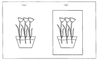
- the method for preserving cut flowers is roughly divided into a chemical solution system that absorbs the life-extending agent into the cut flowers, and an inert gas or the like as shown in FIG. 11 (b).
- an inert gas or the like As shown in FIG. 11 (a), the method for preserving cut flowers is roughly divided into a chemical solution system that absorbs the life-extending agent into the cut flowers, and an inert gas or the like as shown in FIG. 11 (b).
- Patent Document 1 discloses a preservation method for maintaining the freshness of roses for a long period of time by storing them at a low temperature under the pressure of xenon gas.
- FIG. 12 is a diagram showing the configuration of the storage device described in Patent Document 1.
- the pressure vessel 101 serving as a cut flower storage device is pressurized by being filled with xenon gas by a xenon gas cylinder 105 after the cut flower is put therein.
- the pressure vessel 101 separated from the xenon gas cylinder 105 is stored at a temperature lower than room temperature in a refrigerated warehouse or the like.
- the pressure vessel 101 maintains the state preserve
- the pressure vessel 101 When collecting cut flowers, first, the pressure vessel 101 is connected to the xenon gas recovery device 106, the xenon gas in the pressure vessel 101 is collected, the lid 117 of the pressure vessel 101 is opened, and the pressure vessel 101 is opened. Collect cut flowers.
- the freshness of cut flowers can be maintained by filling the pressure vessel 101 with xenon gas and maintaining the low temperature state.
- Patent Document 2 discloses a storage system including a storage container for storing cut flowers and the like, a nozzle with a silencer for putting compressed air into the storage container, and an ozone generator for putting ozone into the storage container. .
- a storage container for storing cut flowers and the like
- a nozzle with a silencer for putting compressed air into the storage container
- an ozone generator for putting ozone into the storage container.
- Patent Document 2 requires an ozone generator, which increases the introduction cost and is not economical.
- Patent Documents 1 and 2 require a running cost each time the storage container is filled with xenon gas or ozone gas.
- Patent Documents 1 and 2 have a problem that they are not economical because they are expensive.
- the present invention has been made to solve the above-described problems, and an object of the present invention is to save the plant for a long period of time, and to preserve the plant for a long period of time. Is to provide a method.
- a plant storage container for storing a plant of the present invention has a plant and a liquid to be absorbed by the plant arranged in a hermetically sealed interior.
- the atmospheric pressure is characterized by being higher than atmospheric pressure by being filled only with air.
- a plant preservation method for preserving a plant according to the present invention includes arranging a plant and a liquid that causes the plant to absorb water in a sealed space, and adjusting the pressure of the sealed space. It is characterized by making it higher than atmospheric pressure by filling only air.
- the plant arranged in the sealed interior can be stored for a long time by absorbing the liquid.
- the inside of the said storage container in which the said ornamental plant is arranged is sealed, and the atmospheric
- the air pressure inside the sealed interior is higher than the atmospheric pressure because only air is filled.
- a plant storage container for storing a plant has a hermetically sealed interior in which a plant and a liquid that absorbs water from the plant are disposed.
- the air pressure inside the sealed interior is adjusted by filling only air so that the water absorption amount is less than the water absorption amount of the plant arranged in the sealed interior of the same volume as the sealed interior. It is characterized by being.
- the water absorption amount of the liquid of the plant is less than the water absorption amount of the plant arranged in the sealed interior having the same volume as the sealed interior. For this reason, it is possible to preserve
- the air pressure inside the sealed interior is adjusted by filling only air.
- a plant and a liquid for absorbing water by the plant are arranged in a sealed interior, and the air pressure in the sealed interior is filled only with air. It is higher than atmospheric pressure.
- a plant and a liquid that causes the plant to absorb water are disposed in a sealed interior, and the water absorption amount of the liquid of the plant is the sealed interior.
- the air pressure inside the sealed interior is adjusted by filling only air so that the amount of water absorption of the plant disposed in the sealed interior of the same volume is smaller.
- a plant and a liquid that absorbs water from the plant are arranged in a sealed space, and the air pressure of the sealed space is filled with only air. Make it higher than atmospheric pressure.
- (A) (b) represents the structure of the preservation container of the plant concerning 2nd Embodiment, (a) represents a mode that the preservation container was decomposed
- (A) (b) represents the other structure of the storage container of the plant concerning 2nd Embodiment, (a) represents a mode that the storage container was decomposed
- (A) is a figure showing the preservation
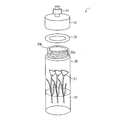
- FIG. 1 is a perspective view showing the configuration of the ornamental plant storage container of the present invention.
- the plant storage container 1 includes a lid 10, a container body 20, a cut flower (plant, ornamental plant) 21, and a liquid 22.
- the storage container 1 is sealed, and one or a plurality of cut flowers 21 and a liquid 22 that absorbs the cut flowers 21 are arranged in the sealed interior.
- the sealed interior of the storage container 1 is filled with compressed air so that the atmospheric pressure is higher than the atmospheric pressure.
- the storage container 1 will be described as a storage container for storing the cut flowers 21 as ornamental plants, but the present invention is not limited thereto, and edible plants may be stored.
- the storage container 1 is configured such that the internal atmospheric pressure is equal to or higher than atmospheric pressure (1 atm) and can withstand up to about 4 atmospheric pressure (atm).
- the liquid 22 may be water such as tap water, or may be a preservative solution to which a component for preserving plants is added, as is generally used.
- the cut flowers 21 are arranged so that the section of the cut stem is immersed in the liquid 22.
- the container body 20 contains a cut flower 21 and a liquid 22 inside.
- the container body 20 has a cylindrical shape and is made of a transparent material.
- the container main body 20 can be comprised from glass, polyester, etc. as an example.
- the lid 10 is a lid for sealing the container body 20.
- the lid 10 is arranged on the upper portion of the container body 20 (near the opposite side when the vicinity of the bottom surface is the lower portion).
- the lid 10 and the container body 20 are formed so as to be removable as will be described later.
- valve (air injection part) 11 for sending compressed air sent from the pump to the inside by being connected to a pump (described later).
- the valve 11 is formed so as to be connectable to a pump described later.
- the compressed air supplied from the pump connected to the valve 11 is supplied to the inside of the storage container 1 through the valve 11.
- the inside of the storage container 1 can be filled with air, and the inside of the storage container 1 can be made higher than atmospheric pressure.
- the valve 11 for example, an English valve, an American valve, a French valve, or the like can be used.
- the storage container 1 for storing the cut flower 21 as an ornamental plant which is an example of a plant, includes the cut flower 21 and the liquid 22 such as water that causes the cut flower 21 to absorb water in a sealed interior. Yes.
- the cut flower 21 and the liquid 22 that causes the cut flower 21 to absorb water are arranged in the storage container 1 that is a sealed space.
- the cut flower 21 disposed in the storage container 1 can be stored for a long period of time by absorbing the liquid 22 so that the cut flower 21 can be viewed by a user or the like for a long period of time.
- the storage container 1 in which the cut flowers 21 are arranged is sealed, and the storage container 1 is higher than atmospheric pressure. For this reason, even if the cut flower 21 arranged in the storage container 1 is not sealed or sealed, it is stored for a long period of time compared with the cut flower stored in a container at normal atmospheric pressure. It is possible.
- the air pressure inside the sealed interior is higher than the atmospheric pressure because only air is filled. That is, the atmospheric pressure in the storage container 1 which is a sealed space is made higher than the atmospheric pressure by filling only air.
- the air filled in the storage container 1 is usually air that exists in the atmosphere.
- xenon gas or ozone gas which is generally used for storage of plants, is a main component. Not what you want.
- the storage container 1 since the air pressure inside the sealed interior is higher than the atmospheric pressure by being filled only with air, it is possible to store the cut flowers 21 arranged inside for a long period of time. This is practical because it is possible to achieve both the effect of being able to save the cut flower 21 easily and economically. For this reason, it is particularly easy to use in ordinary households.
- the atmospheric pressure of the storage container 1 is such that the water absorption amount of the liquid 22 of the cut flower 21 is less than the water absorption amount of the cut flower 21 disposed in a sealed interior having the same volume as the storage container 1. It can be expressed as being adjusted by filling only air.
- the amount of water absorption of the liquid 22 of the cut flower 21 is less than the amount of water absorption of the cut flower disposed in the sealed interior of the same volume as the storage container 1, so that the cut flower 21 disposed in the storage container 1 is removed. It can be stored for a long time.
- the size of the storage container 1 is not particularly limited, for example, the convenience can be improved by setting the storage container 1 to a size that can be carried by one person or both hands.
- the weight and size can be easily carried by a person with one hand or both hands. , Can improve convenience.
- the sealed internal pressure is higher than the atmospheric pressure. For this reason, even if a plurality of cut flowers 21 are arranged in a relatively narrow sealed space that is large enough for a person to carry with one hand or both hands, the long-term preservation effect of the cut flowers 21 arranged therein is long. Can be obtained.
- the container body 20 is cylindrical, it can be easily carried by hand, and the convenience can be improved.
- the storage container 1 a long-term storage effect can be obtained, and the convenience is high and it is very practical.
- the air pressure inside the storage container 1 is specifically 1.5 atmospheres (atm) or more. Thereby, the long-term preservation effect of the cut flowers 21 arranged in the storage container 1 can be obtained.
- the pressure inside the sealed container 1 is 4 atmospheres (atm) or less.
- the storage container 1 can be configured with a simple configuration, which is economical.
- the sealed internal pressure of the storage container 1 is 2 atm or more and 4 atm or less.
- FIG. 2 is a perspective view showing a state in which the ornamental plant storage container of the present invention is disassembled.
- the storage container 1 further includes a packing (sealing member) 30 disposed between the lid 10 and the container body 20.
- the upper part 20a of the container body 20 is an area where the lid 10 is disposed (covered).
- the outer side surface of the upper portion 20 a of the container body 20 is recessed from the other side surface (outer side surface) of the container body 20.
- a spiral groove is disposed on the outer side surface of the upper portion 20a of the container body 20.
- An opening 20b is provided inside the upper part 20a of the container body 20.
- the opening 20b is used for storing the cut flower 21 and the liquid 22 in the container main body 20, taking out the cut flower 21 and the liquid 22 stored in the container main body 20, and allowing compressed air sent through the valve 11 to pass therethrough. It is.
- a spiral groove corresponding to a spiral groove provided on the outer side surface of the upper portion 20a of the container body 20 is formed on the inner side surface of the lid 10.
- the spiral groove formed on the inner side surface of the lid 10 and the spiral groove formed on the outer side surface of the upper portion 20a of the container body 20 are fitted. Thereby, the lid
- a packing (sealing member) 30 is disposed between the lid 10 and the upper part 20a of the container body 20.
- the packing 30 is for preventing air from leaking between the lid 10 and the upper part of the container body 20.
- the packing 30 has a circular shape, and is made of rubber as an example.
- the packing 30 may be arranged so that air does not leak from between the lid 10 and the container body 20 when the lid 10 is attached to the container body 20.
- the packing 30 is passed through the upper part 20a of the container body 20 so as to expose a spiral groove formed in the upper part 20a of the container body 20.
- the lid 10 is attached to the upper portion 20a of the container main body 20, so that when the lid 10 is attached to the container main body 20, the packing 30 is disposed between the upper portion 20a of the container main body 20 and the lid 10. It has become so.
- a groove into which the packing 30 is fitted is provided on the inner side surface of the lid 10 or the back surface with respect to the upper surface (the surface facing the upper portion 20a of the container body 20), and the packing 30 is fitted into the groove.
- the packing 30 may be arranged between the upper portion 20 a of the container main body 20 and the lid 10.
- the packing 30 is disposed between the lid 10 and the upper portion 20a of the container body 20, and the lid 10 and the container body 20 are hermetically sealed, so that the gap between the lid 10 and the container body 20 is reduced. Since it can be filled, even if the inside of the storage container 1 is pressurized with air, the air can be prevented from leaking outside.
- the storage container 1 includes the lid 10 that seals the inside of the container body 20 by closing the opening 20b. Thereby, by removing the lid 10 from the container main body 20, the cut flower 21 accommodated in the container main body 20 can be replaced, or the amount of the liquid 22 in the container main body 20 can be adjusted.
- the air pressure inside the storage container 1 may be higher than the atmospheric pressure by being filled with only air.
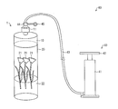
- FIG. 3 is a diagram showing the configuration of the ornamental plant preservation system of the present invention.
- the ornamental plant storage system 60 includes a storage container 1 and a pump 40.
- the pump 40 is for compressing air and injecting the compressed air into the storage container 1.
- the pump 40 includes a pump main body 41, a pressing portion 42, a tube 43, a connecting portion 44, and a pressure gauge 45.
- the pressing portion 42 is inserted into the pump main body 41 with the handle portion exposed.
- the pressing portion 42 is arranged so as to be movable up and down in the pump main body 41.
- One end of the tube 43 is connected to the pump main body 41, and a connecting portion 44 and a pressure gauge 45 are provided at the other end.
- the connecting portion 44 is configured to be connectable to the valve 11 provided on the lid 10.
- the pressure gauge 45 is for measuring the pressure in the storage container 1.
- the storage system 60 may be configured such that the pressure gauge 45 is omitted from the pump 40 and the pressure gauge 45 is provided separately from the pump 40.
- connection portion 44 of the pump 40 is attached to the valve 11 of the lid 10 by a user or the like.
- the air is compressed in the pump main body 41 when the pressing unit 42 is pressed by the user or the like. Then, the compressed air passes through the tube 43 and is injected into the storage container 1 through the connection portion 44 and the valve 11.
- the pressure in the storage container 1 can be adjusted so that the pressure in the storage container 1 is 1.5 atm (atm) higher than atmospheric pressure and 4 atm (atm) or lower.
- the storage system 60 includes the storage container 1 and the pump 40, the storage container 1 is filled with only air from the pump 40 so that the inside of the storage container 1 becomes higher than the atmospheric pressure. Can be adjusted.
- the inventors of the present application conducted experiments on the effect of a high-pressure environment pressurized only with air on the storage state of ornamental plants using the plant storage device 50 shown in FIG.
- the plant storage device 50 includes a pressure-resistant container (high-pressure growth chamber) 51, a gas supply pipe 52 that supplies compressed air to the pressure-resistant container 51, and a gas discharge pipe 53 that discharges air from the pressure-resistant container 51.
- the pressure vessel 51 is provided with a metal halide lamp 54 for irradiating light.
- the observation window 56 and the lighting window 57 are made of quartz glass.
- Condition A conditions that are the environment in which the pressure in the pressure vessel 51 is maintained at normal pressure
- condition B conditions that are the atmospheric pressure in the pressure-resistant vessel 51 was maintained at 2 atm, and the other conditions were set to conditions A (this is referred to as condition B).
- Condition B the compressed air was sent to the pressure vessel 51 through the gas supply pipe 52, so that the pressure inside the pressure vessel 51 was maintained at 2 atm by injecting only air.
- condition C a condition that is a normal atmospheric pressure environment that is not sealed is created.
- FIG. 6 is a table summarizing experimental conditions and experimental results according to this example.
- Condition A is that the air pressure: 1 atm (atm), temperature: 16 ° C. or higher and 23 ° C. or lower, and light intensity: 250 ⁇ mol / m 2 ⁇ s are maintained in an enclosed high-pressure growth chamber (pressure vessel 51).
- pressure vessel 51 At the beginning (at the start of the experiment), the water content in the vase was 400 ml, and the water content in the vase 8 days after the input (start of the experiment) was 325 ml.
- Condition B is that the air pressure: 2 atm (atm), the temperature: 16 ° C. to 23 ° C., and the light intensity: 250 ⁇ mol / m 2 ⁇ s in the environment of the sealed high-pressure growth chamber (within the pressure vessel 51).
- the water content in the vase was 400 ml
- the water content in the vase 8 days after the input (start of the experiment) was 350 ml.
- Condition C is an atmosphere of a normal cultivation room that is not hermetically sealed. Atmospheric pressure: 1 atm (atm), temperature: 23 ° C. or higher and 28 ° C. or lower, light intensity: 200 ⁇ mol / m 2 ⁇ s, initially (experimental) At the start, the water content in the vase was 400 ml, and the water content in the vase 8 days after input (start of the experiment) was 250 ml.
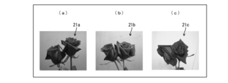
- FIG. 7 shows the state of roterose immediately before the start of the experiment.
- 7 (a) shows the rotellose 21a immediately before entering the condition A
- FIG. 7 (b) shows the rotellose 21b immediately before entering the condition B
- FIG. 7 (c) shows the condition C Roteroses 21c immediately before being put into the are shown.
- FIG. 8 shows the state of roterose 8 days after the start of the experiment.
- 8 (a) shows the rotellose 21a 8 days after the introduction to the condition A
- FIG. 8 (b) shows the rotose 21b 8 days after the introduction to the condition B
- FIG. 8 (c) shows the condition C Shows the rotellose 21c after 8 days of introduction.
- necrosis was suppressed in the rotellose 21b under the condition B in which the pressure inside the pressure vessel 51 was kept at 2 atm.
- condition A the water content in the vase 8 days after the input was 325 ml
- condition B it was 350 ml.
- the rotellose 21b can further obtain a water absorption suppressing effect because the stored environment was higher than the atmospheric pressure.
- the amount of water absorbed in the vase of the rosette 21b in the pressure vessel 51 (condition B: 50 ml) is the amount of water absorbed in the vase of the rosette 21a in the pressure vessel 51 (condition A: 75 ml). It has been found that the air pressure in the pressure vessel 51 may be adjusted by filling only air so as to reduce the pressure.
- the cut flower 21 is stored in a sealed container, and further, the water inside the container to be stored is set to a pressure higher than the atmospheric pressure, such as about 2 atm. It can be stored for a long time.
- the air pressure in the container for storing the cut flowers 21 should be set higher than the atmospheric pressure, even if the pressure in the container for storing the cut flowers 21 is about 1.5 atm, It is conceivable that water absorption can be suppressed and the product can be stored for a long time.
- FIG. 9 represent the structure of the storage container concerning the 2nd Embodiment of this invention
- (a) is a perspective view showing a mode that the storage container was decomposed
- (b) is a lid
- the storage container 2 is different from the storage container 1 described in Embodiment 1 in that the lid 10 and the container body 25 are detachable by a catch clip 70.
- the storage container 2 includes a container body 25 instead of the container body 20 of the storage container 1, and further includes a catch clip 70.
- the container body 25 is different from the container body 20 in that a spiral groove is not formed on the outer side surface of the upper portion 25a of the container body 25.
- Other configurations of the container body 25 are the same as those of the container body 20.
- the storage container 2 is provided with catch clips 70 arranged on two sides.
- the catch clip 70 includes a receiving member 71 and a catch clip main body 72.
- the receiving member 71 is disposed on the side surface (outer side surface) of the lid 10 at two positions facing each other.
- the receiving member 71 is configured by forming a frame from an elongated metal material.
- the storage container 2 can be reduced in weight by reducing the amount of the metal material of the receiving member 71.
- the catch clip main body 72 is arranged on the side surface (outer side surface) of the container main body 25 at two positions facing each other.
- the catch clip main body 72 is disposed at a position where the catch clip main body 72 engages with the receiving member 71 disposed on the lid 10 when the lid 10 is closed.
- the catch clip main body 72 includes a base member 73, an operation lever 74, a spring member 75, and a hooking member (fixing member) 76. On the surface of the base member 73, an operation lever 74, a spring member 75, and a hooking member 76 are disposed. The back surface of the base member 73 is bonded to the side surface of the container body 25.
- the operation lever 74 is for moving the hook member 76 up and down. When the operation lever 74 is lifted, the hook member 76 moves upward, and when the operation lever 74 is pressed, the hook member 76 moves downward.
- Two spring members 75 are arranged on both side surfaces of the operation lever 74, respectively.
- the spring member 75 connects the operation lever 74 and the hook member 76.
- the spring member 75 pulls the hooking member 76 by an elastic action. Thereby, the spring member 75 fixes the receiving member 71 engaged with the hooking member 76.
- the hook member 76 is engaged with the receiving member 71 by being hooked on the bent portion of the receiving member 71, and fixes the receiving member 71 engaged therewith.
- a packing 30 is disposed between the lid 10 and the upper portion 25a of the container body 25. In the present embodiment, no spiral groove is formed on the inner side surface of the lid 10.
- the storage container 1 When the storage container 1 is hermetically sealed by fitting the lid 10 formed with a spiral groove with each other and the upper portion 20a of the container body 20 like the storage container 1 described above, the lid 10, the container body 20, The packing 30 in between is worn out.
- the storage container 2 is provided with the receiving member 71 on the side surface of the lid 10 as described above, and the receiving member 71 to be engaged with the outer side surface of the container main body 25 by the elastic action of the spring member 75.
- a hooking member 76 to be fixed is arranged.
- the lid 10 and the container body 25 are fixed by the receiving member 71 and the hooking member 76 that engages with the receiving member 71. For this reason, like the storage container 1, a spiral groove is provided in each of the lid 10 and the upper part 20a of the container body 20, and the lid 10 and the container body 20 Compared to the case of fixing, in the storage container 2, it is possible to prevent the packing 30 disposed between the lid 10 and the upper portion 25a of the container body 25 from being worn.
- catch clips 70 is not limited to two, and it is sufficient that the storage container 1 can be sealed by fixing the lid 10 and the container body 25, and may be three or more.
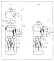
- catch clip is not limited to the one shown in FIG. 9, and the one shown in FIGS. 10 (a) and 10 (b) may be used.
- FIGS. 10A and 10B show another configuration of the storage container according to the second embodiment of the present invention
- FIG. 10A is a perspective view showing a state in which the storage container is disassembled.
- FIG. 4 is a perspective view showing a storage container with a lid closed.
- 10 (a) and 10 (b) is different from the storage container 2 in that a catch clip 80 is provided instead of the catch clip 70.
- the catch clip 80 includes a receiving member 81 and a catch clip body 82.
- the catch clip body 82 includes a base member 83, an operation lever 84, a spring member 85, and a hooking member 86.
- the base member 83, the operation lever 84, the spring member 85, and the hooking member 86 have the same configurations as the base member 73, the operation lever 74, the spring member 75, and the hooking member 76 described above.
- the receiving member 81 is not formed by a frame made of a thin metal material like the receiving member 71, but a plate-like metal piece is bent at a bent portion. Therefore, the receiving member 81 is stronger than the receiving member 71 and has a shape that is not easily damaged.
- the plant and the liquid that causes the plant to absorb water are disposed in the sealed interior, and the air pressure in the sealed interior is air. It is characterized by being higher than atmospheric pressure by being filled only with.
- the plant and the liquid that causes the plant to absorb water are arranged in a sealed space, and the air pressure of the sealed space is changed to only air. It is characterized by being higher than atmospheric pressure by filling.
- the plant arranged in the sealed interior can be stored for a long time by absorbing the liquid.
- the inside of the said storage container in which the said ornamental plant is arranged is sealed, and the atmospheric
- the air pressure inside the sealed interior is higher than the atmospheric pressure because only air is filled.
- the plant and the liquid that causes the plant to absorb water are arranged in a sealed interior, and the water absorption amount of the liquid of the plant is
- the air pressure inside the sealed interior is adjusted by being filled only with air so as to be less than the amount of water absorption of the plant disposed in the sealed interior of the same volume as the sealed interior. It is characterized by.
- the water absorption amount of the liquid of the plant is less than the water absorption amount of the plant arranged in the sealed interior having the same volume as the sealed interior. For this reason, it is possible to preserve
- the air pressure inside the sealed interior is adjusted by filling only air.
- the air pressure inside the sealed interior is preferably 1.5 atm or more and 4 atm or less. Thereby, the long-term preservation effect of the plant arranged in the sealed interior can be obtained.
- the air pressure inside the sealed interior is preferably 2 atm or more and 4 atm or less. Thereby, the long-term preservation effect of the said plant can be acquired reliably.
- cover which makes the said container main body the airtight state by plugging the opening provided in the said container main body in order to store the said plant and the said liquid And are preferably provided.
- the plant housed in the container body can be replaced, or the amount of the liquid in the container body can be adjusted.
- an air injection part for sending compressed air sent from the pump to the inside is formed on the upper surface of the lid by being connected to the pump.
- a spiral groove is formed on the outer side surface of the upper part of the container body, which is an area to which the lid is attached, and the spiral groove is fitted to the inner side surface of the lid. It is preferable. Thereby, the said lid
- a sealing member for preventing air from leaking between the lid and the upper portion of the container body is disposed between the lid and the upper portion of the container body. Thereby, it can prevent that air leaks between the said lid
- a receiving member is disposed on a side surface of the lid, and a fixing member is disposed on an outer side surface of the container body to fix the engaging member to be engaged by an elastic action. It is preferable that a sealing member for preventing air from leaking between the lid and the upper portion of the container main body is disposed between the upper portion of the container main body.
- the lid and the container body are fixed by the receiving member and a fixing member that engages with the receiving member.
- a spiral groove is provided in each of the lid and the container main body, and by fitting each groove, the lid and the container main body are compared with the case where the lid is fixed. It is possible to prevent the sealing member disposed between the lid and the container body from being worn.
- the container body is preferably cylindrical. Thereby, since it is easy to carry with a user's hand etc., the convenience can be improved.
- the plant is preferably an ornamental plant. Since the plant can be stored for a long period of time, the plant or the like can be viewed for a long period of time by a user or the like.
- the plant storage system of the present invention preferably includes the storage container and a pump for supplying compressed air to the storage container.
- a pump for supplying compressed air to the storage container.
- the present invention can be used for a storage container, a storage system, and a storage method that require a plant to be stored economically for a long period of time.
- Storage container 10 Lid 10a Upper surface 11 Valve (Air injection part) 20.25 Container body 20b Opening 21 Cut flowers (plants, ornamental plants) 22 Liquid 30 Packing (sealing member) 40 pump 50 plant storage device 51 pressure vessel 60 storage system 70/80 catch clip 71/81 receiving member 76/86 hook member (fixing member)
Landscapes
- Life Sciences & Earth Sciences (AREA)
- Environmental Sciences (AREA)
- Packging For Living Organisms, Food Or Medicinal Products That Are Sensitive To Environmental Conditiond (AREA)
- Packages (AREA)
- Closures For Containers (AREA)
Abstract
植物を保存する植物の保存容器(1)は、密閉された内部に、切り花(21)と、切り花(21)に吸水させる液体(22)とが配されており、保存容器(1)内部の気圧は、空気のみが充填されることで、大気圧より高い。これにより、経済的であり、かつ、植物を長期間、保存することができる。
Description
本発明は、植物を保存するための保存容器、保存システム及び保存方法に関する。
近年、切り花の需要が高まっており、さまざまな、切り花を保存する方法が検討されている。
切り花の保存方法には大きく分けて、図11の(a)に示すように、延命剤を切り花に吸水させる薬液方式と、図11の(b)に示すように、不活性ガスなどを封入した雰囲気中に切り花を置き、枯死に影響のあるエチレンガスの抑制や呼吸の抑制を促すガス封入式との2種類があり、どちらも延命に関して一定の効果を挙げている。
特許文献1には、薔薇を、キセノンガスの圧力下で低温貯蔵することにより、薔薇の鮮度を長期間保つ保存方法が開示されている。
図12は、特許文献1に記載の保存装置の構成を表す図である。
図12に示すように、切り花保存装置である耐圧容器101は、切り花が入れられてから、キセノンガスボンベ105によりキセノンガスが充填されることで加圧されている。そして、耐圧容器101内のキセノンガスの分圧が所定の値となると、キセノンガスボンベ105と切り離された耐圧容器101は、冷蔵倉庫等で、常温より低温で保存される。そして、耐圧容器101は、低温で保存された状態を維持することで、流通工程を通して、切り花の鮮度が保たれる。
そして、切り花を回収する際は、まず、耐圧容器101をキセノンガス回収装置106と接続し、耐圧容器101内のキセノンガスを回収したのち、耐圧容器101の蓋117を開いて、耐圧容器101内の切り花を回収する。
このようにして、耐圧容器101にキセノンガスを充填し、さらに、低温状態を維持することで、切り花の鮮度を保つことができる。
特許文献2には、切り花等を保存する保存容器と、当該保存容器に圧縮空気を入れるサイレンサー付きノズルと、上記保存容器にオゾンを入れるオゾン発生装置とを備えている保存システムが開示されている。このように、特許文献2では、切り花を保存する保存容器に、圧縮空気を入れると共に、オゾンも当該保存容器に入れることで、保存容器内の切り花に対する殺菌効果を得ることが記載されている。
しかしながら、特許文献1の耐圧容器101を用いた方法では、再利用可能とはいえ、キセノンガスを導入するためのキセノンガスボンベ105や、キセノンガスを回収するためのキセノンガス回収装置106が必要であり、導入コストが高くなり、経済的な切り花の保存方法ではない。
特許文献2の保存システムも同様に、オゾン発生装置が必要であり、導入コストが高くなり、経済的ではないという課題が生じる。
さらに、特許文献1、2とも、キセノンガス又はオゾンガスを保存容器内に充填するたびにランニングコストがかかる。
このように、特許文献1、2に開示された技術では、コストがかかるので経済的ではないという課題が生じる。
本発明は、上記の問題点を解決するためになされたもので、その目的は、経済的であり、かつ、植物を長期間、保存することが可能な植物の保存容器、保存システム、及び保存方法を提供することである。
上記の課題を解決するために、本発明の植物を保存する植物の保存容器は、密閉された内部に、植物と、上記植物に吸水させる液体とが配されており、上記密閉された内部の気圧は、空気のみが充填されることで、大気圧より高いことを特徴としている。
上記の課題を解決するために、本発明の植物を保存する植物の保存方法は、密閉された空間に、植物と、上記植物に吸水させる液体とを配し、上記密閉された空間の気圧を、空気のみを充填することで、大気圧より高くすることを特徴としている。
上記構成によると、上記密閉された内部に配されている上記植物は、上記液体を吸収することで長期保存が可能である。
そして、上記構成によると、上記観賞用植物が配されている上記保存容器内は密閉されており、かつ、その内部の気圧は大気圧より高い。このため、上記保存容器内の密閉された内部に配されている上記観賞用植物を、長期間保存することが可能である。
さらに、上記構成によると、上記密閉された内部の気圧は、空気のみが充填されることで、大気圧より高くなっている。
このため、特殊な気体を、上記密閉された内部に充填するための充填装置は必要ない。このため、手軽であり、かつ、導入コストを抑えることができるので、経済的である。
このように、上記構成によると、上記密閉された内部に配されている上記植物を長期間、保存することができる効果と、手軽で経済的に上記植物を保存することができる効果との両立を図ることができる。
上記の課題を解決するために、本発明の植物を保存する植物の保存容器は、密閉された内部に、植物と、上記植物に吸水させる液体とが配されており、上記植物の上記液体の吸水量が、上記密閉された内部と同体積の密閉された内部に配された植物の吸水量より少なくなるように、上記密閉された内部の気圧が、空気のみが充填されることで、調整されていることを特徴としている。
上記構成によると、上記植物の上記液体の吸水量が、上記密閉された内部と同体積の密閉された内部に配された植物の吸水量より少ない。このため、上記保存容器内の密閉された内部に配されている上記植物を、長期間保存することが可能である。
さらに、上記構成によると、上記密閉された内部の気圧は、空気のみが充填されることで、調整されている。
このため、特殊な気体を上記密閉された内部に充填するための充填装置は必要ない。このため、手軽であり、かつ、導入コストを抑えることができるので経済的である。
このように、上記密閉された内部に配されている上記植物を長期間、保存することができる効果と、手軽で経済的に上記植物を保存することができる効果との両立を図ることができる。
本発明の植物を保存する植物の保存容器は、密閉された内部に、植物と、上記植物に吸水させる液体とが配されており、上記密閉された内部の気圧は、空気のみが充填されることで、大気圧より高い。
本発明の植物を保存する植物の保存容器は、密閉された内部に、植物と、上記植物に吸水させる液体とが配されており、上記植物の上記液体の吸水量が、上記密閉された内部と同体積の密閉された内部に配された植物の吸水量より少なくなるように、上記密閉された内部の気圧が、空気のみが充填されることで、調整されている。
本発明の植物を保存する植物の保存方法は、密閉された空間に、植物と、上記植物に吸水させる液体とを配し、上記密閉された空間の気圧を、空気のみを充填することで、大気圧より高くする。
これにより、経済的であり、かつ、植物を長期間、保存することが可能であるという効果を奏する。
〔実施の形態1〕
以下、本発明の第1の実施の形態について、詳細に説明する。
以下、本発明の第1の実施の形態について、詳細に説明する。
〔観賞用植物の保存容器の構成〕
図1は、本発明の観賞用植物の保存容器の構成を表す斜視図である。
図1は、本発明の観賞用植物の保存容器の構成を表す斜視図である。
図1に示すように、植物の保存容器1は、蓋10と、容器本体20と、切り花(植物、観賞用植物)21と、液体22とを備えている。
保存容器1は密閉されており、密閉された内部に、一又は複数の切り花21と、切り花21に吸水させる液体22とが配されている。保存容器1の密閉された内部は、圧縮空気が充填されることで、大気圧より気圧が高くなっている。一例として、保存容器1は、観賞用植物としての切り花21を保存するための保存容器であるものとして説明するが、これに限定されず、食用の植物を保存してもよい。
保存容器1は、内部の気圧が、大気圧(1atm)以上であり、4気圧(atm)程度まで耐えることが可能なように構成されている。
液体22は、水道水等の水であってもよいし、一般的に使用されているような、植物の保存用の成分が添加された保存液であってもよい。切り花21は、切断された茎の断面が、液体22に浸かるように配されている。
容器本体20は、内部に、切り花21と、液体22とを収納している。容器本体20は、円筒形状であり、透明な材料から構成されている。容器本体20は、一例として、ガラスやポリエステル等から構成することができる。
蓋10は、容器本体20を密閉するための蓋である。蓋10は、容器本体20の上部(底面近傍を下部とした場合の反対側近傍)に配されている。蓋10と、容器本体20とは、後述するように、取り外し可能なように形成されている。
蓋10の上面10aには、ポンプ(後述する)と接続されることで、当該ポンプから送られてくる圧縮空気を、内部に送るバルブ(空気注入部)11が形成されている。
バルブ11は、後述するポンプと接続可能なように形成されている。バルブ11に接続されたポンプから供給されてきた圧縮空気は、バルブ11を介して、保存容器1の内部へと供給される。これにより、保存容器1内部に、空気を充填することができ、保存容器1内を大気圧より高くすることができる。バルブ11として、例えば、英式バルブや、米式バルブ、又は仏式バルブなどを用いることができる。
このように、植物の一例である観賞用植物としての切り花21を保存する保存容器1は、密閉された内部に、切り花21と、切り花21に吸水させる、水等の液体22とが配されている。
すなわち、密閉された空間である保存容器1内に、切り花21と、切り花21に吸水させる液体22とを配する。
これにより、この保存容器1内に配されている切り花21に、液体22を吸水させることで長期保存が可能であるので、切り花21を、ユーザ等に、長期間、鑑賞させることができる。
そして、切り花21が配されている保存容器1内は密閉されており、かつ、その保存容器1内が大気圧より高い。このため、保存容器1内に配されている切り花21を、密閉されておらず、又は密閉されていたとしても、通常の大気圧の容器内で保存されている切り花と比べて長期間保存することが可能である。
さらに、保存容器1では、密閉された内部の気圧は、空気のみが充填されることで、大気圧より高くなっている。すなわち、密閉された空間である保存容器1内の気圧を、空気のみを充填することで、大気圧より高くする。
ここで、保存容器1に充填する空気は、通常に、大気中に存在している空気であり、例えば、キセノンガスやオゾンガス等、一般的に植物の保存用に使用される気体を主成分とするものではない。
このため、例えば、上述した特許文献1で用いられているキセノンガスや、特許文献2で用いられているオゾンガス等、特殊な気体を用いる必要がない。
これにより、キセノンガスや、オゾンガス等の特殊な気体を保存容器1内に充填するための充填装置は必要ない。さらに、保存容器1内の空気を、キセノンガスやオゾンガス等に置換する必要はないので、保存容器1内の空気を一旦排気するための減圧装置なども必要がなく、また、保存容器1はこのような減圧に耐えうる構造でなくともよい。
このため、手軽であり、かつ、導入コストを抑えることができるので経済的である。
すなわち、保存容器1によると、密閉された内部の気圧は、空気のみが充填されることで、大気圧より高くなっているので、内部に配されている切り花21を長期間、保存することができる効果と、手軽で経済的に切り花21を保存することができる効果との両立を図ることができるので実用的である。このため、特に、一般家庭で用いやすい。
換言すると、保存容器1は、切り花21の液体22の吸水量が、保存容器1と同体積の密閉された内部に配された切り花21の吸水量より少なくなるように、保存容器1の気圧が、空気のみが充填されることで調整されていると表現することができる。
このように、切り花21の液体22の吸水量が、保存容器1と同体積の密閉された内部に配された切り花の吸水量より少ないことで、保存容器1内に配されている切り花21を、長期間保存することが可能である。
保存容器1の大きさは、特に限定されるものではないが、例えば、人が片手、又は両手で持ち運びできる程度の大きさとすることで、利便性を向上させることができる。
具体的には、一例として、保存容器1内の体積を、300cm3以上100cm3以下程度とすることで、人が片手、又は両手で持ち運びを手軽に行う程度の重さや大きさとすることができ、利便性を向上させることができる。
上述したように、保存容器1では、密閉された内部の気圧が大気圧より高くなっている。このため、人が片手、又は両手で持ち運びできる程度の大きさである比較的、狭い密閉空間の内部に、複数の切り花21を配しても、内部に配した切り花21の長期間の保存効果を得ることができる。
また、容器本体20は円筒形状なので、手で持ち運びをし易く、さらに、利便性を向上させることができる。
このように、保存容器1によると、長期間の保存効果を得ることができ、かつ、利便性が高く、非常に実用的である。
保存容器1の密閉された内部の気圧は、具体的には、1.5気圧(atm)以上となっている。これにより、保存容器1内に配された切り花21の長期間の保存効果を得ることができる。
さらに、保存容器1の密閉された内部の気圧は、4気圧(atm)以下となっている。これにより、簡単な構成で、保存容器1を構成することができるので、経済的である。
このように、保存容器1の密閉された内部の気圧を1.5気圧(atm)以上4気圧以下とすることで、長期間の保存効果を得ることができると共に、経済的な保存容器1を構成することができる。すなわち、非常に実用的である。
さらに、保存容器1の密閉された内部の気圧は、2気圧以上4気圧以下であることが、さらに好ましい。保存容器1の密閉された内部の気圧は、2気圧以上とすることで、より、確実に、切り花21の長期間の保存効果を得ることができる。
また、図2に示すように、保存容器1は、蓋10と、容器本体20とを取り外し可能である。図2は、本発明の観賞用植物の保存容器を分解した様子を表す斜視図である。
図2に示すように、保存容器1は、さらに、蓋10と、容器本体20との間に配されるパッキン(密閉部材)30を備えている。
容器本体20の上部20aは、蓋10が配される(被される)領域である。容器本体20の上部20aの外側側面は、容器本体20の他の側面(外側側面)より窪んでいる。そして、容器本体20の上部20aの外側側面には、螺旋状の溝が配されている。
容器本体20の上部20aの内側には開口20bが設けられている。開口20bは、切り花21や液体22を容器本体20に収納したり、容器本体20内に収納されている切り花21や液体22を取り出したり、バルブ11を通じて送られてくる圧縮空気が通るためのものである。
蓋10の内側側面には、図示しないが、容器本体20の上部20aの外側側面に設けられている螺旋状の溝と対応する螺旋状の溝が形成されている。この蓋10の内側側面に形成された螺旋状の溝と、容器本体20の上部20aの外側側面に形成された螺旋状の溝とを嵌合させる。これにより、蓋10と、容器本体20とが密閉される。
さらに、蓋10と、容器本体20の上部20aとの間には、パッキン(密閉部材)30が配されている。パッキン30は、蓋10と、容器本体20の上部との間から空気が漏れることを防止するためのものである。パッキン30は、円形状をしており、一例として、ゴム製である。
パッキン30は、容器本体20に蓋10が取り付けられたとき、蓋10と、容器本体20との間から、空気が漏れないように配されればよい。
パッキン30は、容器本体20の上部20aに形成されている螺旋状の溝を露出させるように、容器本体20の上部20aに通される。
そして、その後、蓋10が容器本体20の上部20aに取り付けられることで、容器本体20に蓋10が取り付けられたとき、パッキン30が容器本体20の上部20aと、蓋10との間に配されるようになっている。
又は、例えば、蓋10の内側の側面、もしくは上面に対する裏面(容器本体20の上部20aと対向する側の面)に、パッキン30を嵌め込む溝を設け、その溝にパッキン30が嵌め込まれることで、容器本体20に、蓋10が取り付けられたとき、パッキン30が容器本体20の上部20aと、蓋10との間に配されるような構成にしてもよい。
このように、蓋10と、容器本体20の上部20aとの間に、パッキン30を配し、蓋10と、容器本体20とを密閉することで、蓋10と、容器本体20との隙間を埋めることができるので、保存容器1の内部を空気で加圧したとしても、その空気が、外部に漏れることを防止することができる。
上述したように、保存容器1は、開口20bを塞ぐことで容器本体20内を密閉状態とする蓋10を備えている。これにより、蓋10を、容器本体20から取り外すことで、容器本体20内に収納されている切り花21を取り替えたり、容器本体20内の液体22の液量を調整したりすることができる。
また、上述したように、保存容器1の内部の気圧は、空気のみが充填されることで、大気圧より高くなればよい。
このため、キセノンガスや、オゾンガス等の特殊な気体を充填するための装置が無くても、保存容器1内の切り花21が枯れた場合に、新しい切り花21に取り替えたり、容器本体20内の液体22の液量を調整したりすることを、手軽に行うことができる。
(観賞用植物の保存装置の構成)
次に、図3を用いて、保存容器1の内部を加圧するためのポンプを備える観賞用植物の保存システムについて説明する。図3は、本発明の観賞用植物の保存システムの構成を表す図である。
次に、図3を用いて、保存容器1の内部を加圧するためのポンプを備える観賞用植物の保存システムについて説明する。図3は、本発明の観賞用植物の保存システムの構成を表す図である。
図3に示すように、観賞用植物の保存システム60は、保存容器1と、ポンプ40とを備えている。
ポンプ40は、空気を圧縮して、その圧縮空気を保存容器1内へと注入するためのものである。
ポンプ40は、ポンプ本体41と、押下部42と、チューブ43と、接続部44と、圧力計45とを備えている。
押下部42は、取っ手部分を露出させて、ポンプ本体41に挿入されている。押下部42は、ポンプ本体41内を上下可動が可能なように配されている。チューブ43は、一方の端部はポンプ本体41に接続されており、他方の端部には接続部44と、圧力計45とが設けられている。
また、接続部44は、蓋10に設けられたバルブ11と接続可能なように構成されている。圧力計45は、保存容器1内の圧力を測定するためのものである。
なお、保存システム60は、ポンプ40から圧力計45を省略し、圧力計45をポンプ40とは別に設ける構成としてもよい。
ここで、広く一般家庭で使用されている自転車のタイヤのチューブに設けられた空気注入用のバルブは、一般的に、英式バルブが多く使用されている。
このため、蓋10に設けられたバルブ11として英式バルブを用いた場合、ポンプ40として、広く一般家庭で使用されている自転車のタイヤのチューブに空気を注入するためのポンプを用いることができる。
密閉された保存容器1の内部を空気により加圧する場合、まず、図3に示すように、ポンプ40の接続部44が、蓋10のバルブ11に、ユーザ等によって取り付けられる。
次に、ユーザ等により、押下部42が押下されることで、ポンプ本体41内で、空気が圧縮される。そして、その圧縮空気は、チューブ43内を通り、接続部44及びバルブ11を介して、保存容器1内へと注入される。
そして、接続部44に設けられた圧力計により、保存容器1内の圧力が、大気圧より高い1.5気圧(atm)以上4気圧(atm)以下となるように調整を行うことができる。
このように、保存システム60は、保存容器1と、ポンプ40とを備えているので、ポンプ40から保存容器1に、空気のみを充填することで、保存容器1内を大気圧より高くするように調整することができる。
〔実施例〕
次に、図4~図8を用いて本発明の実施例について説明する。
次に、図4~図8を用いて本発明の実施例について説明する。
本願の発明者らは、図4に示す植物保存装置50を用いて、空気のみで加圧した高圧環境下が、観賞用植物の保存状態に与える影響について実験を行った。
図4に示すように、植物保存装置50は、耐圧容器(高圧グロースチャンバ)51、耐圧容器51に圧縮空気を供給するガス供給管52、および、耐圧容器51から空気を排出するガス排出管53、耐圧容器51内に光を照射するメタルハライドランプ54などを備えている。
耐圧容器51には、植物を保存させるための水を溜めておく培養液収容部55、植物の品質の劣化の様子を外部から観察するための観察窓56、および、メタルハライドランプ54からの照射光を容器内へ採り込む採光窓57などが設けられている。観察窓56および採光窓57は、石英ガラスで形成されている。
本実施例では、図4および図5に示す植物保存装置50を2基用いて、各設備内において、耐圧容器51内の気圧を常圧に保持した環境である条件(これを、条件Aとする)と、耐圧容器51内の気圧を2気圧に保持し、それ以外の環境を条件Aに合わせた環境である条件(これを、条件Bとする)とをそれぞれつくった。
条件Bでは、ガス供給管52により、圧縮空気を耐圧容器51に送ることで、耐圧容器51内の気圧を、空気のみを注入することで2気圧に保持した。
さらに、植物保存装置50を用いず、密閉されていない通常の大気圧の環境である条件(これを、条件Cとする)をつくった。
そして、それぞれの環境下において、バラの一種であるローテローゼの切り花を通常の水道水を入れた花瓶に指し、8日間保持した。
図6は、本実施例にかかる実験条件及び実験結果をまとめた図である。
条件Aは、密閉された高圧グロースチャンバ内(耐圧容器51内)の環境下で、気圧:1気圧(atm)、温度:16℃以上23℃以下、光強度:250μmol/m2・sを保持し、当初(実験開始時)花瓶内水分量:400ml、投入(実験開始)8日後の花瓶内水分量:325mlであった。
条件Bは、密閉された高圧グロースチャンバ内(耐圧容器51内)の環境下で、気圧:2気圧(atm)、温度:16℃以上23℃以下、光強度:250μmol/m2・sを保持し、当初(実験開始時)花瓶内水分量:400ml、投入(実験開始)8日後の花瓶内水分量:350mlであった。
条件Cは、密閉されていない通常の栽培室の環境下で、気圧:1気圧(atm)、温度:23℃以上28℃以下、光強度:200μmol/m2・sを保持し、当初(実験開始時)花瓶内水分量:400ml、投入(実験開始)8日後の花瓶内水分量:250mlであった。
図7は、実験開始直前のローテローゼの状態を示している。図7の(a)は、条件Aに投入する直前のローテローゼ21aを示し、図7の(b)は、条件Bに投入する直前のローテローゼ21bを示し、図7の(c)は、条件Cに投入する直前のローテローゼ21cを示している。
図8は、実験開始8日後のローテローゼの状態を示している。図8の(a)は、条件Aに投入8日後のローテローゼ21aを示し、図8の(b)は、条件Bに投入8日後のローテローゼ21bを示し、図8の(c)は、条件Cに投入8日後のローテローゼ21cを示している。
図8に示すように、耐圧容器51内の気圧を2気圧に保持した条件Bでのローテローゼ21bは、壊死が抑制されていることが分かった。
また、図6から、当初花瓶内水分量と、投入8日後の花瓶水分量とを比較すると、条件A・B・Cとも、当初400mlであった花瓶内の水分量が、条件Cにおいてはローテローゼ21cの吸水により投入8日後には250mlへと減少していた。
一方、条件Aにおいては投入8日後の花瓶内水分量は325mlであり、条件Bにおいては350mlであった。これにより、条件A及び条件Bでは、条件Cより、ローテローゼ21a・21bの吸水が抑えられたことが分かった。
すなわち、条件A及び条件Bと、条件Cとの花瓶内水分量の比較結果より、ローテローゼ21a・21bは、保存した環境を密閉状態としたことで、吸水抑制効果が得られたことが分かった。
さらに、条件Aと条件Bとの花瓶内水分量の比較結果より、ローテローゼ21bは、保存した環境が大気圧より高かったので、さらに、吸水の抑制効果を得ることができることが分かった。
換言すると、耐圧容器51内のローテローゼ21bの花瓶内の水の吸水量(条件B:50ml)が、条件Aでの耐圧容器51内のローテローゼ21aの花瓶内の水の吸水量(条件A:75ml)より少なくなるように、耐圧容器51内の気圧を、空気のみを充填することで、調整すればよいことが分かった。
以上の実験結果から、密閉した容器で切り花21を保存し、さらに、その保存する容器内を、2気圧程度のように、大気圧より高い気圧とすることで、切り花21の吸水を抑制し、長期間、保存することが可能であることが考えられる。
この場合、密閉した容器を加圧する気体は空気のみであっても、充分に、切り花21の吸水を抑制し、長期間、保存することが可能であることが分かる。
さらに、切り花21を保存する容器内の気圧は、大気圧より高く設定すればよいと考えられるので、切り花21を保存する容器内の気圧を、1.5気圧程度としても同様に、切り花21の吸水を抑制し、長期間、保存することが可能であることが考えられる。
〔実施の形態2〕
次に、本発明の第2の実施の形態について説明する。
次に、本発明の第2の実施の形態について説明する。
図9の(a)(b)は、本発明の第2の実施形態にかかる保存容器の構成を表し、(a)は保存容器を分解した様子を表す斜視図であり、(b)は蓋を閉じた状態の保存容器を表す斜視図である。
保存容器2は、キャッチクリップ70によって、蓋10と、容器本体25とが取り外し可能なように構成されている点で、実施の形態1で説明した保存容器1と相違する。
図9の(a)(b)に示すように、保存容器2は、保存容器1の容器本体20に替えて、容器本体25を備え、さらに、キャッチクリップ70を備えている。
容器本体25は、容器本体25の上部25aの外側側面には、螺旋状の溝が形成されていない点で、容器本体20と相違する。容器本体25の他の構成は、容器本体20と同様である。
保存容器2は、側面の2箇所に配されているキャッチクリップ70を備えている。
キャッチクリップ70は、受け部材71と、キャッチクリップ本体72とから構成されている。
受け部材71は、蓋10の側面(外側側面)に、2箇所、互いに対向する位置に配されている。受け部材71は、細長い金属材料により、フレームが形成されることで構成されている。このように、受け部材71の金属材料の量を少なくすることで、保存容器2の軽量化を行うことができる。
キャッチクリップ本体72は、容器本体25の側面(外側側面)に、2箇所、互いに対向する位置に配されている。キャッチクリップ本体72は、蓋10を閉じたとき、蓋10に配されている受け部材71と係合するような位置に配されている。
キャッチクリップ本体72は、ベース部材73と、操作レバー74と、バネ部材75と、引掛部材(固定部材)76とを備えている。ベース部材73の表面に、操作レバー74と、バネ部材75と、引掛部材76とが配されている。そして、ベース部材73の裏面は、容器本体25の側面と接着されている。
操作レバー74は、引掛部材76を上下可動させるためのものである。操作レバー74を持ち上げることで、引掛部材76は上方へ移動し、操作レバー74を押圧すると、引掛部材76下方へ移動する。
バネ部材75は、2個配されており、操作レバー74の両側面にそれぞれ配されている。
バネ部材75は、操作レバー74と、引掛部材76とを接続するものである。そして、受け部材71と、引掛部材76とが係合しているとき、操作レバー74が押圧されると、バネ部材75は、引掛部材76を弾性作用により引っ張る。これにより、バネ部材75は、引掛部材76と係合している受け部材71を固定する。
引掛部材76は、受け部材71の屈曲部分に引掛けられることで、受け部材71と係合し、その係合している受け部材71を固定するためのものである。
蓋10を閉じる場合、操作レバー74を、指などで持ち上げると、引掛部材76は上方へ移動する。そして、引掛け部材76を、蓋10の受け部材71の屈曲部分に引掛け(係合させ)、操作レバー74を押圧する。すると、バネ部材75の弾性作用により、受け部材71と、キャッチクリップ本体72とが固定される。これにより、蓋10と、容器本体25とが固定される。
なお、蓋10と、容器本体25の上部25aとの間には、パッキン30が配されている。また、本実施の形態では、蓋10の内側側面には、螺旋状の溝は形成されていない。
このようにして、蓋10によって、容器本体25は密閉される。
上述した保存容器1のように、互いに螺旋状の溝が形成された蓋10及び容器本体20の上部20aとを嵌合させて、保存容器1を密閉する場合、蓋10と、容器本体20との間のパッキン30が磨耗することになる。
一方、保存容器2は、上述したように蓋10の側面には受け部材71が配されており、容器本体25の外側側面には、係合する受け部材71を、バネ部材75の弾性作用により固定する引掛部材76が配されている。
このため、蓋10と、容器本体25とは、受け部材71と、受け部材71と係合する引掛部材76とによって固定される。このため、保存容器1のように、蓋10と、容器本体20の上部20aとのそれぞれに、螺旋状の溝を設け、それぞれの溝を嵌合させることで、蓋10と、容器本体20と固定する場合と比べて、保存容器2では、蓋10と、容器本体25の上部25aとの間に配されているパッキン30が磨耗することを防止することができる。
なお、キャッチクリップ70の個数は2個に限定されず、蓋10と、容器本体25とを固定することで、保存容器1を密閉することができればよく、3個以上であってもよい。
また、キャッチクリップは、図9に示したものに限定されず、図10の(a)(b)に示すようなものを用いてもよい。
図10の(a)(b)は、本発明の第2の実施形態にかかる保存容器の他の構成を表し、(a)は保存容器を分解した様子を表す斜視図であり、(b)は蓋を閉じた状態の保存容器を表す斜視図である。
図10の(a)(b)に示す保存容器3は、キャッチクリップ70に替えて、キャッチクリップ80を備えている点で保存容器2と相違する。
キャッチクリップ80は、受け部材81と、キャッチクリップ本体82とから構成されている。
キャッチクリップ本体82は、ベース部材83と、操作レバー84と、バネ部材85と、引掛部材86とを備えている。ベース部材83と、操作レバー84と、バネ部材85と、引掛部材86とは、上述したベース部材73と、操作レバー74と、バネ部材75と、引掛部材76と同様の構成である。
受け部材81は、受け部材71のように、細い金属材料により、フレームが形成されて構成されているものではなく、板状の金属片が、屈曲部分で折り曲げられた形状をしている。このため、受け部材81は、受け部材71と比べて丈夫であり、破損し難い形状となっている。
なお、本発明は上述した各実施形態に限定されるものではなく、請求項に示した範囲で種々の変更が可能であり、異なる実施形態にそれぞれ開示された技術的手段を適宜組み合わせて得られる実施形態についても本発明の技術的範囲に含まれる。
以上のように、本発明の植物を保存する植物の保存容器は、密閉された内部に、植物と、上記植物に吸水させる液体とが配されており、上記密閉された内部の気圧は、空気のみが充填されることで、大気圧より高いことを特徴としている。
以上のように、本発明の植物を保存する植物の保存方法は、密閉された空間に、植物と、上記植物に吸水させる液体とを配し、上記密閉された空間の気圧を、空気のみを充填することで、大気圧より高くすることを特徴としている。
上記構成によると、上記密閉された内部に配されている上記植物は、上記液体を吸収することで長期保存が可能である。
そして、上記構成によると、上記観賞用植物が配されている上記保存容器内は密閉されており、かつ、その内部の気圧は大気圧より高い。このため、上記保存容器内の密閉された内部に配されている上記観賞用植物を、長期間保存することが可能である。
さらに、上記構成によると、上記密閉された内部の気圧は、空気のみが充填されることで、大気圧より高くなっている。
このため、特殊な気体を、上記密閉された内部に充填するための充填装置は必要ない。このため、手軽であり、かつ、導入コストを抑えることができるので、経済的である。
このように、上記構成によると、上記密閉された内部に配されている上記植物を長期間、保存することができる効果と、手軽で経済的に上記植物を保存することができる効果との両立を図ることができる。
以上のように、本発明の植物を保存する植物の保存容器は、密閉された内部に、植物と、上記植物に吸水させる液体とが配されており、上記植物の上記液体の吸水量が、上記密閉された内部と同体積の密閉された内部に配された植物の吸水量より少なくなるように、上記密閉された内部の気圧が、空気のみが充填されることで、調整されていることを特徴としている。
上記構成によると、上記植物の上記液体の吸水量が、上記密閉された内部と同体積の密閉された内部に配された植物の吸水量より少ない。このため、上記保存容器内の密閉された内部に配されている上記植物を、長期間保存することが可能である。
さらに、上記構成によると、上記密閉された内部の気圧は、空気のみが充填されることで、調整されている。
このため、特殊な気体を上記密閉された内部に充填するための充填装置は必要ない。このため、手軽であり、かつ、導入コストを抑えることができるので経済的である。
このように、上記密閉された内部に配されている上記植物を長期間、保存することができる効果と、手軽で経済的に上記植物を保存することができる効果との両立を図ることができる。
また、上記密閉された内部の気圧は、1.5気圧以上4気圧以下であることが好ましい。これにより、上記密閉された内部に配された上記植物の長期間の保存効果を得ることができる。
また、上記密閉された内部の気圧は、2気圧以上4気圧以下であることが好ましい。これにより、確実に、上記植物の長期間の保存効果を得ることができる。
また、上記植物、及び上記液体を収納する容器本体と、上記植物、及び上記液体を収納するために上記容器本体に設けられている開口を塞ぐことで、上記容器本体内を密閉状態とする蓋と、を備えていることが好ましい。
上記構成により、上記蓋を、上記容器本体から取り外すことで、上記容器本体内に収納されている上記植物を取り替えたり、上記容器本体内の上記液体の液量を調整したりすることができる。
また、上記蓋の上面には、ポンプと接続されることで、当該ポンプから送られてくる圧縮空気を、内部に送る空気注入部が形成されていることが好ましい。これにより、上記空気注入部に、上記ポンプを接続することで、上記密閉された内部に、空気を充填することができ、大気圧より高くすることができる。
また、上記蓋が取り付けられる領域である上記容器本体の上部のうち、外側側面には、螺旋状の溝が形成されており、上記螺旋状の溝と、上記蓋の内側側面とが嵌合されていることが好ましい。これにより、上記蓋と、上記容器本体とを密閉させることができる。
また、上記蓋と、上記容器本体の上部との間に、上記蓋と、上記容器本体の上部と間から空気が漏れることを防止するための密閉部材が配されていることが好ましい。これにより、上記蓋と、上記容器本体との間から空気が漏れることを防止することができる。
また、上記蓋の側面には受け部材が配されており、上記容器本体の外側側面には、係合する上記受け部材を弾性作用により固定する固定部材が配されており、上記蓋と、上記容器本体の上部との間に、上記蓋と、上記容器本体の上部と間から空気が漏れることを防止するための密閉部材が配されていることが好ましい。
上記構成により、上記蓋と、上記容器本体とは、上記受け部材と、当該受け部材と係合する固定部材とによって固定される。このため、例えば、上記蓋と、上記容器本体とのそれぞれに、螺旋状の溝を設け、それぞれの溝を嵌合させることで、上記蓋と、上記容器本体と固定する場合と比べて、上記蓋と、上記容器本体との間に配されている密閉部材が磨耗することを防止することができる。
また、上記容器本体は、円筒形であることが好ましい。これにより、ユーザの手等で持ち運びがしやすいので、利便性を向上させることができる。
また、上記植物は観賞用植物であることが好ましい。上記植物は長期保存が可能であるので、上記植物を、ユーザ等に長期間、鑑賞させることができる。
本発明の植物の保存システムは、上記保存容器と、当該保存容器に圧縮空気を供給するためのポンプとを備えているが好ましい。上記構成により、上記ポンプから、空気のみを上記保存容器に充填し、上記保存容器内の気圧を大気圧より高くするように調整することができる。
本発明は、植物を、経済的に、長期間保存することが要求される保存容器、保存システム、及び保存方法に利用することができる。
1・2・3 保存容器
10 蓋
10a 上面
11 バルブ(空気注入部)
20・25 容器本体
20b 開口
21 切り花(植物、観賞用植物)
22 液体
30 パッキン(密閉部材)
40 ポンプ
50 植物保存装置
51 耐圧容器
60 保存システム
70・80 キャッチクリップ
71・81 受け部材
76・86 引掛部材(固定部材)
10 蓋
10a 上面
11 バルブ(空気注入部)
20・25 容器本体
20b 開口
21 切り花(植物、観賞用植物)
22 液体
30 パッキン(密閉部材)
40 ポンプ
50 植物保存装置
51 耐圧容器
60 保存システム
70・80 キャッチクリップ
71・81 受け部材
76・86 引掛部材(固定部材)
Claims (13)
- 植物を保存する植物の保存容器であって、
密閉された内部に、植物と、上記植物に吸水させる液体とが配されており、
上記密閉された内部の気圧は、空気のみが充填されることで、大気圧より高いことを特徴とする植物の保存容器。 - 植物を保存する植物の保存容器であって、
密閉された内部に、植物と、上記植物に吸水させる液体とが配されており、
上記植物の上記液体の吸水量が、上記密閉された内部と同体積の密閉された内部に配された植物の吸水量より少なくなるように、
上記密閉された内部の気圧が、空気のみが充填されることで、調整されていることを特徴とする植物の保存容器。 - 上記密閉された内部の気圧は、1.5気圧以上4気圧以下であることを特徴とする請求項1又は2に記載の植物の保存容器。
- 上記密閉された内部の気圧は、2気圧以上4気圧以下であることを特徴とする請求項3に記載の植物の保存容器。
- 上記植物、及び上記液体を収納する容器本体と、
上記植物、及び上記液体を収納するために上記容器本体に設けられている開口を塞ぐことで、上記容器本体内を密閉状態とする蓋と、
を備えていることを特徴とする請求項1又は2に記載の植物の保存容器。 - 上記蓋の上面には、ポンプと接続されることで、当該ポンプから送られてくる圧縮空気を、内部に送る空気注入部が形成されていることを特徴とする請求項5に記載の植物の保存容器。
- 上記蓋が取り付けられる領域である上記容器本体の上部のうち、外側側面には、螺旋状の溝が形成されており、上記螺旋状の溝と、上記蓋の内側側面とが嵌合されていることを特徴とする請求項5又は6に記載の植物の保存容器。
- 上記蓋と、上記容器本体の上部との間に、上記蓋と、上記容器本体の上部と間から空気が漏れることを防止するための密閉部材が配されていることを特徴とする請求項5~7の何れか1項に記載の植物の保存容器。
- 上記蓋の側面には受け部材が配されており、
上記容器本体の外側側面には、係合する上記受け部材を弾性作用により固定する固定部材が配されており、
上記蓋と、上記容器本体の上部との間に、上記蓋と、上記容器本体の上部と間から空気が漏れることを防止するための密閉部材が配されていることを特徴とする請求項5又は6に記載の植物の保存容器。 - 上記容器本体は、円筒形であることを特徴とする請求項5~9の何れか1項に記載の植物の保存容器。
- 上記植物は観賞用植物であることを特徴とする請求項1~10の何れか1項に記載の植物の保存容器。
- 請求項1~11の何れか1項に記載の植物の保存容器と、当該保存容器に圧縮空気を供給するためのポンプとを備えていることを特徴とする植物の保存システム。
- 植物を保存する植物の保存方法であって、
密閉された空間に、植物と、上記植物に吸水させる液体とを配し、
上記密閉された空間の気圧を、空気のみを充填することで、大気圧より高くすることを特徴とする植物の保存方法。
Priority Applications (1)
| Application Number | Priority Date | Filing Date | Title |
|---|---|---|---|
| JP2012540790A JP5843203B2 (ja) | 2010-10-25 | 2011-10-18 | 植物の保存容器、保存システム及び保存方法 |
Applications Claiming Priority (2)
| Application Number | Priority Date | Filing Date | Title |
|---|---|---|---|
| JP2010-238677 | 2010-10-25 | ||
| JP2010238677 | 2010-10-25 |
Publications (1)
| Publication Number | Publication Date |
|---|---|
| WO2012056948A1 true WO2012056948A1 (ja) | 2012-05-03 |
Family
ID=45993661
Family Applications (1)
| Application Number | Title | Priority Date | Filing Date |
|---|---|---|---|
| PCT/JP2011/073964 Ceased WO2012056948A1 (ja) | 2010-10-25 | 2011-10-18 | 植物の保存容器、保存システム及び保存方法 |
Country Status (2)
| Country | Link |
|---|---|
| JP (1) | JP5843203B2 (ja) |
| WO (1) | WO2012056948A1 (ja) |
Cited By (1)
| Publication number | Priority date | Publication date | Assignee | Title |
|---|---|---|---|---|
| KR20180000608U (ko) * | 2016-08-23 | 2018-03-06 | 권종달 | 농산물 물류 상자 |
Citations (4)
| Publication number | Priority date | Publication date | Assignee | Title |
|---|---|---|---|---|
| JPS63248679A (ja) * | 1987-03-30 | 1988-10-14 | 大河内 正夫 | 生花包装体 |
| JPH04356138A (ja) * | 1991-05-31 | 1992-12-09 | Iwasaki Electric Co Ltd | 切り花の鮮度保持方法 |
| JPH04133188U (ja) * | 1991-05-29 | 1992-12-10 | 株式会社渋谷電機製作所 | フロン等冷媒を使わない切り花 野菜、食肉などの保存システム |
| JPH08104601A (ja) * | 1994-10-05 | 1996-04-23 | Seiichi Oshita | 切り花の保存方法及び保存装置 |
-
2011
- 2011-10-18 WO PCT/JP2011/073964 patent/WO2012056948A1/ja not_active Ceased
- 2011-10-18 JP JP2012540790A patent/JP5843203B2/ja active Active
Patent Citations (4)
| Publication number | Priority date | Publication date | Assignee | Title |
|---|---|---|---|---|
| JPS63248679A (ja) * | 1987-03-30 | 1988-10-14 | 大河内 正夫 | 生花包装体 |
| JPH04133188U (ja) * | 1991-05-29 | 1992-12-10 | 株式会社渋谷電機製作所 | フロン等冷媒を使わない切り花 野菜、食肉などの保存システム |
| JPH04356138A (ja) * | 1991-05-31 | 1992-12-09 | Iwasaki Electric Co Ltd | 切り花の鮮度保持方法 |
| JPH08104601A (ja) * | 1994-10-05 | 1996-04-23 | Seiichi Oshita | 切り花の保存方法及び保存装置 |
Cited By (1)
| Publication number | Priority date | Publication date | Assignee | Title |
|---|---|---|---|---|
| KR20180000608U (ko) * | 2016-08-23 | 2018-03-06 | 권종달 | 농산물 물류 상자 |
Also Published As
| Publication number | Publication date |
|---|---|
| JPWO2012056948A1 (ja) | 2014-05-12 |
| JP5843203B2 (ja) | 2016-01-13 |
Similar Documents
| Publication | Publication Date | Title |
|---|---|---|
| US2965936A (en) | Sterilizing apparatus employing gas | |
| US20190038047A1 (en) | Controlled Atmosphere Storage Case | |
| CN108739971A (zh) | 用于保存食品的系统和方法 | |
| CN105685207A (zh) | 鲜切食用菌的保鲜方法 | |
| JP2013505725A5 (ja) | ||
| JP5843203B2 (ja) | 植物の保存容器、保存システム及び保存方法 | |
| US20080184899A1 (en) | Self pressurizing shelf life extender for food and method | |
| EP2225165B1 (en) | Bottle with cap which keeps the liquid contained in it effervescent and fresh even after partial consumption of the liquid | |
| CA2715990C (en) | A method of treating turf or plants | |
| TWI794319B (zh) | 活性處理水、活性處理水的製造方法、活性處理媒介的製造方法、活性處理水的製造裝置、食品保存方法及活性處理媒介 | |
| CN103057812A (zh) | 食品包装袋 | |
| CN205005668U (zh) | 一种适用于液体培养基的带有内置固定架的培养瓶 | |
| US5863500A (en) | Method and apparatus for preserving products | |
| CN2561735Y (zh) | 分装式低温等离子体真空减压粮食贮藏保鲜装置 | |
| CN207157932U (zh) | 成品茶叶贮存架 | |
| CN107031991A (zh) | 能高质量保存药材的气调箱 | |
| FR2489101A1 (fr) | Procede et dispositif de refrigeration d'un produit notamment agricole | |
| CN202389768U (zh) | 一种抽真空装置及用于该抽真空装置的保鲜盒 | |
| KR200429301Y1 (ko) | 질소가스충진기 | |
| JP2004138171A (ja) | 水素貯蔵方法及び貯蔵装置 | |
| JP2822155B2 (ja) | 切り花の保存方法及び保存装置 | |
| CN106364774B (zh) | 一种果蔬保鲜箱 | |
| KR200454301Y1 (ko) | 식품보관 용기용 에어밸브 | |
| CN203359190U (zh) | 茶叶贮存装置 | |
| CN106982920A (zh) | 一种延长鲜香菇保鲜期的预处理方法 |
Legal Events
| Date | Code | Title | Description |
|---|---|---|---|
| 121 | Ep: the epo has been informed by wipo that ep was designated in this application |
Ref document number: 11836084 Country of ref document: EP Kind code of ref document: A1 |
|
| ENP | Entry into the national phase |
Ref document number: 2012540790 Country of ref document: JP Kind code of ref document: A |
|
| NENP | Non-entry into the national phase |
Ref country code: DE |
|
| 122 | Ep: pct application non-entry in european phase |
Ref document number: 11836084 Country of ref document: EP Kind code of ref document: A1 |