WO2012056791A1 - Distance measurement apparatus - Google Patents
Distance measurement apparatus Download PDFInfo
- Publication number
- WO2012056791A1 WO2012056791A1 PCT/JP2011/068399 JP2011068399W WO2012056791A1 WO 2012056791 A1 WO2012056791 A1 WO 2012056791A1 JP 2011068399 W JP2011068399 W JP 2011068399W WO 2012056791 A1 WO2012056791 A1 WO 2012056791A1
- Authority
- WO
- WIPO (PCT)
- Prior art keywords
- channel
- distance
- measurement
- amplitude
- value
- Prior art date
Links
Images


Classifications
-
- G—PHYSICS
- G01—MEASURING; TESTING
- G01S—RADIO DIRECTION-FINDING; RADIO NAVIGATION; DETERMINING DISTANCE OR VELOCITY BY USE OF RADIO WAVES; LOCATING OR PRESENCE-DETECTING BY USE OF THE REFLECTION OR RERADIATION OF RADIO WAVES; ANALOGOUS ARRANGEMENTS USING OTHER WAVES
- G01S13/00—Systems using the reflection or reradiation of radio waves, e.g. radar systems; Analogous systems using reflection or reradiation of waves whose nature or wavelength is irrelevant or unspecified
- G01S13/74—Systems using reradiation of radio waves, e.g. secondary radar systems; Analogous systems
- G01S13/82—Systems using reradiation of radio waves, e.g. secondary radar systems; Analogous systems wherein continuous-type signals are transmitted
- G01S13/84—Systems using reradiation of radio waves, e.g. secondary radar systems; Analogous systems wherein continuous-type signals are transmitted for distance determination by phase measurement
Definitions
- the present invention relates to a distance measuring device used for distance measurement by detecting a phase of a radio wave reciprocating a measurement target distance.
- a distance measurement system including a master communication device that transmits radio waves and a slave communication device that returns radio waves received from the master communication device.
- a radio wave is transmitted from the master communication device to the slave communication device, and the slave communication device receives the radio wave and returns the radio wave to the master communication device in synchronization with the received radio wave.
- the master communication device receives the radio wave returned from the slave communication device, and measures the distance from the phase information of the received signal to the slave communication device.
- indirect waves such as reflected waves are included in addition to direct waves as radio waves propagating between the master communication device and the slave communication device. If direct waves and indirect waves are mixed, the measurement accuracy decreases, so the received signal is fast Fourier transformed to separate the direct waves and indirect waves on the time axis, and the phase information of only the direct waves is extracted for distance measurement.
- Patent Document 1 There is a measurement method used (Patent Document 1). For example, the received frequency range of the received signal is divided into multiple channels in the gorge band, the received signal is fast Fourier transformed for each channel to detect the phase of the direct wave of each channel, and the measurement target distance is determined from the phase difference between adjacent channels. taking measurement.
- the present invention has been made in view of such a point, and an object of the present invention is to provide a distance measuring device that has a small amount of calculation compared to a method using Fourier transform and the like and can sufficiently improve distance measuring accuracy.
- an object of the present invention is to provide a distance measuring device that has a small amount of calculation compared to a method using Fourier transform and the like and can sufficiently improve distance measuring accuracy.
- the distance measuring device of the present invention includes a reference oscillator that outputs an oscillation signal having a frequency corresponding to each of a plurality of continuous channels in a frequency direction within a predetermined frequency range, and a transmission unit that transmits a transmission signal of each channel using the oscillation signal.
- a reception signal that is returned for each channel from the measurement target that has received the transmission signal of each channel, or a reception unit that receives a reflection signal for each channel from the measurement target, and each reply signal received by the reception unit Alternatively, an amplitude phase measurement unit that measures the reception amplitude phase of each reflected signal for each channel, a storage unit that can store the reception amplitude phase measurement value measured for each channel by the amplitude phase measurement unit, and the measurement target
- An arithmetic unit that calculates a distance between the arithmetic units, and the arithmetic unit processes received amplitude phase measurement values of a plurality of channels extracted from the storage unit.
- the predetermined frequency range it is determined whether or not there is a local maximum value where the reception amplitude is larger than that of a peripheral channel including an adjacent channel, or a local minimum value where the reception amplitude is small, and the local maximum value and the local minimum value do not exist.
- the phase difference between the adjacent channels in the predetermined frequency range is averaged, and the distance to the measurement object is calculated using the average value of the phase difference. Since the signal intensity is expressed by the square of the amplitude, the amplitude can be read as the signal intensity.
- the phase difference between adjacent channels is averaged. For this reason, the influence of the phase distortion of the received signal resulting from the multipath wave can be reduced and the influence of the noise can be reduced without performing complicated processing such as Fourier transform. Thereby, it is possible to reduce the amount of calculation related to the distance calculation and sufficiently increase the distance calculation accuracy.
- the distance measuring device of the present invention transmits a reference oscillator that outputs an oscillation signal having a frequency corresponding to each of a plurality of continuous channels in a frequency direction within a predetermined frequency range, and transmits a transmission signal of each channel using the oscillation signal.
- a transmission means a return signal returned for each channel from the measurement object that received the transmission signal of each channel, or a reception means for receiving a reflected signal for each channel from the measurement object; and each received by the reception means
- An amplitude phase measurement unit that measures the reception amplitude phase of the return signal or each reflected signal for each channel, a storage unit that can store the reception amplitude phase measurement value measured for each channel by the amplitude phase measurement unit, and the measurement target
- a calculation unit that calculates a distance between the received amplitude phase measurement values of a plurality of channels extracted from the storage unit Processing to determine whether or not there is a local maximum value in which the reception amplitude is larger than a peripheral channel including an adjacent channel, or a local minimum value in which the reception amplitude is small, in the predetermined frequency range, the local maximum value exists, And when the minimum value does not exist, or when the minimum value exists and the maximum value does not exist, the adjacent channels having the maximum or minimum amplitude difference among the adjacent channels are specified.
- the distance measuring device of the present invention transmits a reference oscillator that outputs an oscillation signal having a frequency corresponding to each of a plurality of continuous channels in a frequency direction within a predetermined frequency range, and transmits a transmission signal of each channel using the oscillation signal.
- a transmission means a return signal returned for each channel from the measurement object that received the transmission signal of each channel, or a reception means for receiving a reflected signal for each channel from the measurement object; and each received by the reception means
- An amplitude phase measurement unit that measures the reception amplitude phase of the return signal or each reflected signal for each channel, a storage unit that can store the reception amplitude phase measurement value measured for each channel by the amplitude phase measurement unit, and the measurement target
- a calculation unit that calculates a distance between the received amplitude phase measurement values of a plurality of channels extracted from the storage unit Processing to determine whether or not there is a local maximum value in which the reception amplitude is larger than a peripheral channel including an adjacent channel, or a local minimum value in which the reception amplitude is small, in the predetermined frequency range, and the local maximum value and the local minimum value Is present, the distance to the measurement object is calculated using an average value of phase differences between adjacent channels from the frequency position at which the maximum value is reached to the frequency position at which the minimum value is obtained
- the distance measuring device of the present invention transmits a reference oscillator that outputs an oscillation signal having a frequency corresponding to each of a plurality of continuous channels in a frequency direction within a predetermined frequency range, and transmits a transmission signal of each channel using the oscillation signal.
- a transmission means a return signal returned for each channel from the measurement object that received the transmission signal of each channel, or a reception means for receiving a reflected signal for each channel from the measurement object; and each received by the reception means
- An amplitude phase measurement unit that measures the reception amplitude phase of the return signal or each reflected signal for each channel, a storage unit that can store the reception amplitude phase measurement value measured for each channel by the amplitude phase measurement unit, and the measurement target
- a calculation unit that calculates a distance between the received amplitude phase measurement values of a plurality of channels extracted from the storage unit Processing to determine whether or not there is a local maximum value in which the reception amplitude is larger than a peripheral channel including an adjacent channel, or a local minimum value in which the reception amplitude is small, in the predetermined frequency range, and the local maximum value and the local minimum value Is not present, the phase difference between adjacent channels in the predetermined frequency range is averaged, the distance to the measurement object is calculated using the phase difference average value, the local maximum value exists, and the
- the distance to the measurement target is calculated using the phase difference between adjacent channels, and when the maximum value and the minimum value exist, the frequency position where the maximum value is obtained is calculated. Or characterized in that by using the average value of the phase difference between the adjacent channels to the frequency position at which the serial minimum value to calculate the distance to the measurement target.
- the arithmetic unit is a case where the local maximum value and the local minimum value exist, and when there are two or more local maximum values, from the frequency position where the local maximum value is one other There is a case where an average value of phase differences between adjacent channels up to a frequency position having a maximum value is calculated, and a distance from the average value of the phase differences to the measurement object is calculated.
- the arithmetic unit becomes the other local minimum value from the frequency position at which the local minimum value is obtained.
- An average value of phase differences between adjacent channels up to the frequency position may be calculated, and a distance from the average value of the phase differences to the measurement object may be calculated.
- This configuration cancels the effects of multipath waves without performing complex processing such as Fourier transform by using the average value of the phase difference between channels that give maximum values of amplitude or between channels that give minimum values. is doing. For this reason, it is possible to reduce the amount of calculation related to the distance calculation and sufficiently increase the distance calculation accuracy.
- the distance measuring device of the present invention it is possible to separate direct waves and indirect waves without using a fast Fourier transform with a large amount of calculation, reducing the calculation load, and even in a multipath environment. Highly accurate distance measurement can be realized.
- FIG. 1 It is a block diagram which shows the structure of the distance measuring device which concerns on one embodiment of this invention. It is a flowchart of the distance measurement operation
- FIG. 1 is a block diagram showing a configuration example of a distance measuring device according to an embodiment of the present invention.
- the distance measuring device 11 uses a reference oscillator 12 capable of oscillating at a plurality of oscillation frequencies corresponding to the number of channels, and a distance measuring device corresponding to each channel using an oscillation signal output from the reference oscillator 12.
- a transmission system including a transmission unit 13 that generates a transmission signal of, and a transmission antenna 14 that radiates the transmission signal output from the transmission unit 13 by radio waves.
- the transmission unit 13 includes a mixer, a bandpass filter, a power amplifier, and the like, and up-converts the transmission signal to an RF signal using the oscillation frequency. For example, in the frequency range from 2405 MHz to 2480 MHz, a transmission signal can be generated and transmitted on each channel at intervals of 2.5 MHz.
- the distance measuring device 11 measures the distance from the receiving antenna 15, the receiving unit 16 that converts the radio wave received by the receiving antenna 15 into a received signal, and the received signal output from the receiving unit 16.
- a receiving system having a calculation unit 17 is provided.
- the receiving unit 16 includes a low noise amplifier, a mixer, a band pass filter, and the like, and is configured to be able to receive each transmission signal transmitted through the transmission system.
- the calculation unit 17 includes an amplitude phase measurement unit 21 that measures the amplitude and phase of the reception signal, and a storage unit 22 that stores the amplitude and phase of the reception signal for each channel, which is a measurement result measured by the amplitude phase measurement unit 21.
- the amplitude characteristic determination unit 23 that determines the amplitude characteristic based on the amplitude data of the received signal of each channel stored in the storage unit 22 and the distance calculation according to the amplitude characteristic determined by the amplitude characteristic determination unit 23
- a phase difference calculation unit 24 for obtaining a phase difference between channels
- an average value calculation unit 25 for calculating an average value of phase differences between channels in a predetermined frequency range
- an amplitude characteristic determination unit 23 for calculating an average value of phase differences between channels in a predetermined frequency range
- an amplitude characteristic determination unit 23 for calculating an average value of phase differences between channels in a predetermined frequency range
- an amplitude characteristic determination unit 23 for calculating an average value of phase differences between channels in a predetermined frequency range
- an amplitude characteristic determination unit 23 for calculating an average value of phase differences between channels in a predetermined frequency range
- an amplitude characteristic determination unit 23 for calculating an average value of phase differences between channels in a predetermined frequency range
- an amplitude characteristic determination unit 23 for calculating
- the distance measuring device 11 in which the transmission system and the reception system are separated is shown, but for example, the reference oscillator 12 may be shared, and the transmission antenna 14 and the reception antenna 15 may be integrated. Good.
- the amplitude characteristic determining unit 23 divides the amplitude characteristic into patterns based on the amplitude data of the received signal in the reception frequency range. Specifically, the amplitude characteristic pattern of the received signal does not have an extreme value (monotonically increasing or decreasing), a pattern having only one convex extreme value (minimum value), and an upward extreme value ( It is determined which pattern is a pattern having only one maximum value) or a pattern having a plurality of extreme values. Then, based on the determination pattern, the processing content for subsequent distance measurement is switched.
- the phase difference calculation unit 24 specifies the phase difference between adjacent channels from the phase of each channel measured by the amplitude phase measurement unit 21 with the transmission time when the transmission signal of each channel is transmitted from the transmission unit 13 as a time reference. .
- the transmission time of each channel transmitted from the transmission unit 13 may be synchronized with the oscillation operation or the oscillation signal of the reference oscillator 12.
- the method for measuring the phase difference between adjacent channels is not limited to the above method.
- a repeater that has received a transmission signal transmits a signal whose phase is synchronized to the distance measuring device 11, and the distance measuring device 11 that has received the signal measures the distance from the received signal.
- the so-called secondary radar system will be described.
- the present invention can be similarly applied to a so-called primary radar system in which a signal emitted to a measurement target is simply reflected and the reflected wave is received to measure the distance. .
- the distance measuring device 11 transmits the transmission signals of the respective channels in order at predetermined intervals.
- the reference oscillator 12 generates an oscillation signal having an oscillation frequency corresponding to each channel and sequentially supplies the oscillation signal to the transmission unit 13.
- the transmission unit 13 performs frequency conversion using the oscillation signal having an oscillation frequency corresponding to each channel.
- a transmission signal is generated. It is desirable to appropriately set the frequency range and the number of channels (adjacent channel interval) composed of a plurality of channels depending on the application.
- transmission signals of 32 channels at intervals of 2.5 MHz are generated in the frequency range of 2405 MHz to 2480 MHz. In this case, distances up to about 60 m can be measured.
- the repeater (transponder) to be measured receives the distance measurement transmission signal transmitted from the distance measurement device 11, generates a transmission signal whose phase is synchronized with the received transmission signal, and transmits the transmission signal.
- the repeater (transponder) sequentially returns transmission signals of the same channel as the reception channel in response to the transmission signal received for each channel. Therefore, the transmission signal of each channel is transmitted in order from the distance measuring device 11, and the transmission signal of each channel is returned in turn from the repeater (transponder).
- FIG. 2 is a flowchart of distance measurement in the distance measuring device 11 according to the present embodiment.
- the distance measurement device 11 receives a transmission signal transmitted (response transmission) in order from the repeater (transponder) for each channel, the amplitude phase measurement unit 21 of the calculation unit 17 determines the amplitude and phase of the reception signal of each channel. Measure (Step 101).
- the measurement result (amplitude and phase of the received signal for each channel) measured by the amplitude phase measurement unit 21 is stored in the storage unit 22.
- the amplitude characteristic determination unit 23 obtains the amplitude-frequency characteristic based on the amplitude data of the received signal of each channel stored in the storage unit 22, and the maximum value (PEAK) or minimum in the obtained amplitude-frequency characteristic.
- the number of values (NULL) is counted (step 102).
- the amplitude data of the received signal is, for example, discrete data of 32 channels, the amplitude-frequency characteristics obtained from the amplitude data of the received signal are discrete on the frequency axis. That is, the maximum value and the minimum value that can be obtained from the amplitude data of the received signal are not the maximum value and the minimum value in a strict sense.
- the above-mentioned maximum and minimum values are obtained by comparing the amplitude of the target channel with the amplitude of the other channel.
- the maximum value is the maximum value when the amplitude value of each channel is continuously decreased from a position where the amplitude value is continuously increased in the frequency direction in the amplitude-frequency characteristic curve arranged in the frequency axis direction.
- the maximum value is not always one in the entire frequency range (all channels).
- the minimum value refers to the minimum value when the amplitude-frequency characteristic curve continuously increases from a position that continuously decreases in the frequency direction. There is not always one minimum value in the entire frequency range (all channels).
- the distance measuring device 11 classifies the amplitude-frequency characteristics of the received signals of all the channels by a combination of a maximum value (PEAK) and a minimum value (NULL) (PEAK number, NULL number). 0, 0), (1, 0), (0, 1), and ( ⁇ 1, ⁇ 1) are detected.
- PEAK maximum value
- NULL minimum value
- the amplitude characteristic determination unit 23 determines the presence / absence of a local maximum value from the number of local maximum values counted in Step 102 (Step 103). Further, the presence / absence of a minimum value is determined from the number of minimum values counted in step 102 (steps 104 and 105). Then, based on the determination result, a pattern (0, 0) having no extreme value as shown in FIG. 3, a pattern having only one downward extreme value, such as the amplitude-frequency characteristic shown in FIG. (1, 0), a pattern (0, 1) having only one convex extreme value, such as the amplitude-frequency characteristic of FIG. 5, and a pattern having a plurality of extreme values ( ⁇ 1, 1) as shown in FIG. ⁇ 1).
- FIG. 4 and 5 show the amplitude difference-frequency characteristics (the lower part of FIG. 4 and the lower part of FIG. 5) together with the amplitude-frequency characteristics (the upper part of FIG. 4 and FIG. 5).
- the presence or absence of a local minimum is determined.
- the presence or absence of a local maximum may be determined. And whether or not there is a minimum value may be determined at the same time.
- step 106 If it is determined in step 103 and step 104 described above that there is no maximum value and there is no minimum value (FIG. 3), the process proceeds to step 106, and the maximum value exists in step 103 and step 104. Without determining, there is a local minimum value (amplitude-frequency characteristic in FIG. 4), or when it is determined in steps 103 and 105 that there is a local maximum value and there is no local minimum value (in FIG. 5). (Amplitude-Frequency Characteristics) shifts to Step 107, and if Step 103 and Step 105 determine that a local maximum value exists and a local minimum value also exists (FIG. 6), the routine proceeds to Step 108. .
- the presence / absence of a local maximum value or local minimum value is used as a criterion for classifying the amplitude characteristic pattern.
- the influence of the coherent multipath wave is the maximum or minimum value in the amplitude-frequency characteristic. This is because it appears well.
- the distance can be obtained with high accuracy without using a complicated calculation method.
- the average value of the phase difference is calculated in step 106 in the pattern in which the maximum value and the minimum value do not exist.
- the phase difference measurement unit 24 calculates the phase for each channel and detects the phase difference between adjacent channels (sometimes referred to simply as “phase difference”).
- the phase of each channel corresponds to the round-trip distance from the distance measuring device 11 to the repeater, and from the time when the distance measuring device 11 transmits the channel transmission signal to the time when the channel return signal is received from the repeater. Measured as delay time.
- the average value calculator 25 calculates the arithmetic average value of the phase difference. In the case of a pattern having no extreme value as shown in FIG.
- the phase difference between adjacent channels is calculated over the entire frequency range, and the plurality of phase differences are averaged, so the influence of multipath waves can be mitigated and the distance can be accurately measured. Can be requested. As shown in FIG. 3, the average value of the phase differences between adjacent channels in the channels CH 1 to CH N existing in the frequency range is calculated.
- the number of samples related to the calculation of the average value is large. For example, when a transmission signal of 32 channels is used, all the levels that can be obtained from these samples are used. It is desirable to obtain an average value of phase differences, that is, an average value of phase differences in 31 sections.
- the present invention is not limited to this, and the number of samples can be appropriately set according to the target accuracy, required calculation time, the configuration of the distance measuring device, and the like.
- step 107 the phase difference at the maximum value or the minimum value is calculated. For this reason, among the phase differences between the adjacent channels measured by the phase difference measuring unit 24, the phase difference between the adjacent channels having the maximum amplitude difference (the absolute value of the amplitude difference is maximum) is extracted. In the case of a pattern having only one downward extreme value such as the amplitude-frequency characteristic of FIG. 4 or a pattern having only one upward extreme value such as the amplitude-frequency characteristic of FIG.
- the section in which the amplitude difference is maximum is, for example, a section represented by P k in FIG. 4 and a section represented by P k in FIG.
- the phase difference in one section may be used in calculating the distance, or the average value of the phase differences in the two sections may be used. Also good.
- step 108 an average value of phase differences between extreme values is calculated.
- the average value calculation unit 25 calculates the arithmetic average value of the phase differences using the phase difference between adjacent channels measured by the phase difference measurement unit 24.
- an average value of phase differences is calculated in a section between a channel that provides an extreme value and a channel that provides another extreme value.
- the position between adjacent channels is between a channel that gives an extreme value (for example, CHa) and a channel that gives another extreme value (for example, CHb).
- the average value may be obtained between a channel that gives a maximum value and a channel that gives a minimum value, or between two channels that give a maximum value, or between two channels that give a minimum value. You may ask.
- the distance calculation unit 26 calculates the distance between the repeater to be measured and the distance measuring device 11 (step 109).
- the distance L (m) is obtained by the following equation.
- ⁇ a (rad) represents the arithmetic average value of the phase difference obtained in step 106
- c (m ⁇ s ⁇ 1 ) represents the speed of light
- ⁇ f (Hz) represents the frequency interval between adjacent channels.
- N represents the number of sections in the measurement range
- ⁇ i represents the phase difference (rad) in the i-th section.
- the arithmetic average is obtained in all intervals within the measurement range, but the number of intervals related to the calculation of the arithmetic average can be changed as appropriate.
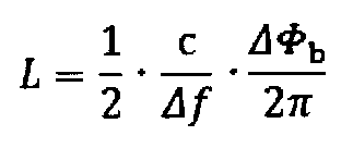
- the distance L (m) is obtained by the following equation.
- ⁇ b (rad) represents the phase difference obtained in step 107, that is, the phase difference between adjacent channels with the maximum amplitude difference
- c (m ⁇ s ⁇ 1 ) represents the speed of light
- ⁇ f (Hz) represents the frequency interval between adjacent channels.
- the distance L (m) is obtained by the following equation.
- ⁇ c (rad) represents the arithmetic average value of the phase difference obtained in step 108 (arithmetic average value of the phase difference between channels giving extreme values)
- c (m ⁇ s ⁇ 1 ) Represents the speed of light
- ⁇ f (Hz) represents the frequency interval between adjacent channels.
- ba represents the number of sections related to the calculation of the average value (the number of sections between channels giving extreme values)
- ⁇ i represents the phase difference (rad) in the i-th section. That is, here, the arithmetic average for the a-th section to the (b-1) -th section is obtained.
- the present embodiment it is possible to reduce the influence of the multipath wave without using Fourier transform by applying appropriate arithmetic processing according to the state of the maximum value and the minimum value of the received signal.
- the load can be reduced, and by applying different arithmetic processing depending on the state of the received signal, distance measurement can be performed with higher accuracy than a distance measurement device using Fourier transform.
- the amplitude-frequency characteristic patterns of the received signal are classified into the four patterns shown in FIGS. 3 to 6, and the distance calculation method is switched according to each pattern. And the distance calculation method have a one-to-one correspondence, a high distance measurement accuracy can be realized for the amplitude-frequency characteristic pattern. Therefore, depending on the application, at least one of steps 106, 107, and 108 may be executed.
- the simulation model using the secondary radar system is shown in FIG.
- a master 201 (corresponding to the distance measuring device 11), a slave 202 (corresponding to a repeater), and a reflecting wall 203 are assumed.
- the frequency range was 2402.5 MHz to 2480 MHz, the channel spacing was 2.5 MHz, and the number of channels was 32.
- the slave 202 When the simulation model shown in FIG. 7A is used, when the master 201 transmits a transmission signal, the slave 202 receives the transmission signal, but the reception signal received by the slave 202 includes the direct wave 211 and the reflected wave 212. Is a synthesized wave (see FIG. 7B). When receiving the synthesized wave, the slave 202 transmits a reply signal in synchronization with a signal whose phase is synchronized with the synthesized wave from the master 201. As a result, the master 201 receives a synthesized wave obtained by synthesizing the direct wave 221 and the reflected wave 222 with respect to the return signal from the slave 202 (see FIG. 7C).
- the distance d 1 between the measurement terminal (master 201 or slave 202) and the reflection wall 203 and the distance d 2 between the measurement terminals are variable, and the distance between the measurement terminals measured by the apparatus and the actual measurement terminal The measurement accuracy is confirmed by comparing with the distance.
- FIG. 8 shows measurement results based on the above simulation model.
- the amplitude when the vertical axis is the distance (m) between the measurement terminal and the reflecting wall 203 and the horizontal axis is the distance (m) between the measurement terminals.
- the distribution of extreme values of frequency characteristics is shown.
- Each region in the figure corresponds to the number of extreme values under the target condition.
- the maximum value and the minimum value are obtained in the upper region in the figure where the pattern of (PEAK, NULL) is ( ⁇ 1, ⁇ 1), that is, in the condition where the distance between the measurement terminal and the reflection wall 203 is large. Value exists.
- FIG. 9 shows the distribution of distance measurement accuracy when the vertical axis is the distance (m) between the measurement terminal and the reflection wall 203 and the horizontal axis is the distance (m) between the measurement terminals.
- Each region in the figure is divided according to the difference between the simulation value and the true value, that is, the magnitude of the measurement error, the region A indicates that the measurement error is small, and the region B has a slight measurement error. It shows that. It can be seen that the measurement error is sufficiently small over the entire measurement range of the example.
- the measurement accuracy of a conventional distance measuring apparatus using Fourier transform and inverse Fourier transform was simulated as a comparative example.
- the conditions such as the measurement system are the same as in the above simulation.
- FIG. 10 shows the distribution of distance measurement accuracy when the vertical axis is the distance (m) between the measurement terminal and the reflection wall 203 and the horizontal axis is the distance (m) between the measurement terminals.
- Each area in the figure is divided according to the difference between the measured value and the true value, that is, the magnitude of the measurement error, the area A indicates that the measurement error is small, and the area B has a slight measurement error.
- Region C shows that the measurement error is large. It can be seen that the method using the Fourier transform and the inverse Fourier transform has a lower measurement accuracy than the example (the method of the present invention).
- the distance measuring apparatus performs appropriate arithmetic processing according to the received signal. For this reason, the influence of multipath waves can be reduced without performing complicated processing such as Fourier transform. That is, there is provided a distance measuring device with a small amount of calculation for calculating the distance and with sufficiently high accuracy.
- the distance measuring device of the present invention can be used for radar, GPS, and other various applications that measure the distance of a measurement target.
Abstract
Description
本実施の形態に係る距離測定装置11は、チャンネル数に対応した複数の発振周波数で発振可能な基準発振器12と、基準発振器12から出力される発振信号を用いて各チャンネルに対応した距離測定用の送信信号を生成する送信部13と、送信部13から出力される送信信号を電波にて放射する送信用アンテナ14とを有する送信系を備える。送信部13は、ミキサ、バンドパスフィルタ、パワーアンプなどを含んで構成され、発振周波数を用いて送信信号をRF信号にアップコンバートする。例えば、2405MHzから2480MHzの周波数範囲において、2.5MHz間隔のチャンネルのそれぞれで送信信号を生成して送信できるように構成されている。 FIG. 1 is a block diagram showing a configuration example of a distance measuring device according to an embodiment of the present invention.
The distance measuring


This application is based on Japanese Patent Application No. 2010-239630 filed on Oct. 26, 2010. All this content is included here.
Claims (6)
- 所定周波数範囲で周波数方向に連続する複数チャンネルにそれぞれ対応した周波数の発振信号を出力する基準発振器と、
前記発振信号を用いて各チャンネルの送信信号を送信する送信手段と、
前記各チャンネルの送信信号を受けた測定対象からチャンネル毎に返信される返信信号、または前記測定対象からのチャンネル毎の反射信号を受信する受信手段と、
前記受信手段で受信した各返信信号または各反射信号の受信振幅位相をチャンネル毎に測定する振幅位相測定部と、
前記振幅位相測定部でチャンネル毎に測定された受信振幅位相測定値を記憶可能な記憶部と、
前記測定対象との間の距離を計算する演算部と、
を備え、
前記演算部は、前記記憶部から取り出した複数チャンネルの受信振幅位相測定値を処理して、前記所定周波数範囲に、隣接チャンネルを含む周辺チャンネルよりも受信振幅が大きくなる極大値、または受信振幅が小さくなる極小値が存在するか否か判定し、
前記極大値および前記極小値が存在しない場合は、前記所定周波数範囲における各隣接チャンネル間の位相差を平均し、該位相差平均値を用いて前記測定対象までの距離を算出することを特徴とする距離測定装置。 A reference oscillator that outputs an oscillation signal having a frequency corresponding to each of a plurality of channels continuous in a frequency direction within a predetermined frequency range;
Transmitting means for transmitting a transmission signal of each channel using the oscillation signal;
A receiving means for receiving a return signal returned for each channel from the measurement target that received the transmission signal of each channel, or a reflected signal for each channel from the measurement target;
An amplitude phase measurement unit for measuring the reception amplitude phase of each reply signal or each reflection signal received by the receiving means for each channel;
A storage unit capable of storing a received amplitude phase measurement value measured for each channel by the amplitude phase measurement unit;
A calculation unit for calculating a distance between the measurement object;
With
The calculation unit processes the reception amplitude phase measurement values of a plurality of channels extracted from the storage unit, and a local maximum value or reception amplitude in which the reception amplitude is larger than a peripheral channel including an adjacent channel in the predetermined frequency range. Determine if there is a local minimum that decreases,
When the maximum value and the minimum value do not exist, the phase difference between adjacent channels in the predetermined frequency range is averaged, and the distance to the measurement object is calculated using the phase difference average value. Distance measuring device. - 所定周波数範囲で周波数方向に連続する複数チャンネルにそれぞれ対応した周波数の発振信号を出力する基準発振器と、
前記発振信号を用いて各チャンネルの送信信号を送信する送信手段と、
前記各チャンネルの送信信号を受けた測定対象からチャンネル毎に返信される返信信号、または前記測定対象からのチャンネル毎の反射信号を受信する受信手段と、
前記受信手段で受信した各返信信号または各反射信号の受信振幅位相をチャンネル毎に測定する振幅位相測定部と、
前記振幅位相測定部でチャンネル毎に測定された受信振幅位相測定値を記憶可能な記憶部と、
前記測定対象との間の距離を計算する演算部と、
を備え、
前記演算部は、前記記憶部から取り出した複数チャンネルの受信振幅位相測定値を処理して、前記所定周波数範囲に、隣接チャンネルを含む周辺チャンネルよりも受信振幅が大きくなる極大値、または受信振幅が小さくなる極小値が存在するか否か判定し、
前記極大値が存在し、かつ、前記極小値が存在しない場合、または、前記極小値が存在し、かつ、前記極大値が存在しない場合は、隣接チャンネル間のうちで振幅差が最大または最小となる隣接チャンネル間を特定し、特定した隣接チャンネル間の前記位相差を用いて前記測定対象までの距離を算出することを特徴とする距離測定装置。 A reference oscillator that outputs an oscillation signal having a frequency corresponding to each of a plurality of channels continuous in a frequency direction within a predetermined frequency range;
Transmitting means for transmitting a transmission signal of each channel using the oscillation signal;
A receiving means for receiving a return signal returned for each channel from the measurement target that received the transmission signal of each channel, or a reflected signal for each channel from the measurement target;
An amplitude phase measurement unit for measuring the reception amplitude phase of each reply signal or each reflection signal received by the receiving means for each channel;
A storage unit capable of storing a received amplitude phase measurement value measured for each channel by the amplitude phase measurement unit;
A calculation unit for calculating a distance between the measurement object;
With
The calculation unit processes the reception amplitude phase measurement values of a plurality of channels extracted from the storage unit, and a local maximum value or reception amplitude in which the reception amplitude is larger than a peripheral channel including an adjacent channel in the predetermined frequency range. Determine if there is a local minimum that decreases,
When the local maximum value exists and the local minimum value does not exist, or when the local minimum value exists and the local maximum value does not exist, the amplitude difference between adjacent channels is maximum or minimum. A distance measuring device characterized in that a distance between adjacent channels is specified, and a distance to the measurement object is calculated using the phase difference between the specified adjacent channels. - 所定周波数範囲で周波数方向に連続する複数チャンネルにそれぞれ対応した周波数の発振信号を出力する基準発振器と、
前記発振信号を用いて各チャンネルの送信信号を送信する送信手段と、
前記各チャンネルの送信信号を受けた測定対象からチャンネル毎に返信される返信信号、または前記測定対象からのチャンネル毎の反射信号を受信する受信手段と、
前記受信手段で受信した各返信信号または各反射信号の受信振幅位相をチャンネル毎に測定する振幅位相測定部と、
前記振幅位相測定部でチャンネル毎に測定された受信振幅位相測定値を記憶可能な記憶部と、
前記測定対象との間の距離を計算する演算部と、
を備え、
前記演算部は、前記記憶部から取り出した複数チャンネルの受信振幅位相測定値を処理して、前記所定周波数範囲に、隣接チャンネルを含む周辺チャンネルよりも受信振幅が大きくなる極大値、または受信振幅が小さくなる極小値が存在するか否か判定し、
前記極大値および前記極小値が存在する場合は、前記極大値となる周波数位置から前記極小値となる周波数位置までの各隣接チャンネル間の位相差の平均値を用いて前記測定対象までの距離を算出することを特徴とする距離測定装置。 A reference oscillator that outputs an oscillation signal having a frequency corresponding to each of a plurality of channels continuous in a frequency direction within a predetermined frequency range;
Transmitting means for transmitting a transmission signal of each channel using the oscillation signal;
A receiving means for receiving a return signal returned for each channel from the measurement target that received the transmission signal of each channel, or a reflected signal for each channel from the measurement target;
An amplitude phase measurement unit for measuring the reception amplitude phase of each reply signal or each reflection signal received by the receiving means for each channel;
A storage unit capable of storing a received amplitude phase measurement value measured for each channel by the amplitude phase measurement unit;
A calculation unit for calculating a distance between the measurement object;
With
The calculation unit processes the reception amplitude phase measurement values of a plurality of channels extracted from the storage unit, and a local maximum value or reception amplitude in which the reception amplitude is larger than a peripheral channel including an adjacent channel in the predetermined frequency range. Determine if there is a local minimum that decreases,
When the local maximum value and the local minimum value exist, the distance to the measurement object is calculated using an average value of phase differences between adjacent channels from the frequency position where the local maximum value is reached to the frequency position where the local minimum value is obtained. A distance measuring device characterized by calculating. - 所定周波数範囲で周波数方向に連続する複数チャンネルにそれぞれ対応した周波数の発振信号を出力する基準発振器と、
前記発振信号を用いて各チャンネルの送信信号を送信する送信手段と、
前記各チャンネルの送信信号を受けた測定対象からチャンネル毎に返信される返信信号、または前記測定対象からのチャンネル毎の反射信号を受信する受信手段と、
前記受信手段で受信した各返信信号または各反射信号の受信振幅位相をチャンネル毎に測定する振幅位相測定部と、
前記振幅位相測定部でチャンネル毎に測定された受信振幅位相測定値を記憶可能な記憶部と、
前記測定対象との間の距離を計算する演算部と、
を備え、
前記演算部は、前記記憶部から取り出した複数チャンネルの受信振幅位相測定値を処理して、前記所定周波数範囲に、隣接チャンネルを含む周辺チャンネルよりも受信振幅が大きくなる極大値、または受信振幅が小さくなる極小値が存在するか否か判定し、
前記極大値および前記極小値が存在しない場合は、前記所定周波数範囲における各隣接チャンネル間の位相差を平均し、該位相差平均値を用いて前記測定対象までの距離を算出し、
前記極大値が存在し、かつ、前記極小値が存在しない場合、または、前記極小値が存在し、かつ、前記極大値が存在しない場合は、隣接チャンネル間のうちで振幅差が最大または最小となる隣接チャンネル間を特定し、特定した隣接チャンネル間の前記位相差を用いて前記測定対象までの距離を算出し、
前記極大値および前記極小値が存在する場合は、前記極大値となる周波数位置から前記極小値となる周波数位置までの各隣接チャンネル間の位相差の平均値を用いて前記測定対象までの距離を算出することを特徴とする距離測定装置。 A reference oscillator that outputs an oscillation signal having a frequency corresponding to each of a plurality of channels continuous in a frequency direction within a predetermined frequency range;
Transmitting means for transmitting a transmission signal of each channel using the oscillation signal;
A receiving means for receiving a return signal returned for each channel from the measurement target that received the transmission signal of each channel, or a reflected signal for each channel from the measurement target;
An amplitude phase measurement unit for measuring the reception amplitude phase of each reply signal or each reflection signal received by the receiving means for each channel;
A storage unit capable of storing a received amplitude phase measurement value measured for each channel by the amplitude phase measurement unit;
A calculation unit for calculating a distance between the measurement object;
With
The calculation unit processes the reception amplitude phase measurement values of a plurality of channels extracted from the storage unit, and a local maximum value or reception amplitude in which the reception amplitude is larger than a peripheral channel including an adjacent channel in the predetermined frequency range. Determine if there is a local minimum that decreases,
When the maximum value and the minimum value do not exist, the phase difference between adjacent channels in the predetermined frequency range is averaged, and the distance to the measurement object is calculated using the phase difference average value.
When the local maximum value exists and the local minimum value does not exist, or when the local minimum value exists and the local maximum value does not exist, the amplitude difference between adjacent channels is maximum or minimum. To determine the distance to the measurement object using the phase difference between the specified adjacent channels,
When the local maximum value and the local minimum value exist, the distance to the measurement object is calculated using an average value of phase differences between adjacent channels from the frequency position where the local maximum value is reached to the frequency position where the local minimum value is obtained. A distance measuring device characterized by calculating. - 前記演算部は、
前記極大値および前記極小値が存在する場合であって前記極大値が二以上存在する場合に、一の極大値となる周波数位置から、他の一の極大値となる周波数位置までの各隣接チャネル間の位相差の平均値を算出し、前記位相差の平均値から前記測定対象までの距離を算出することを特徴とする請求項3または請求項4に記載の距離測定装置。 The computing unit is
When the local maximum value and the local minimum value exist, and there are two or more local maximum values, each adjacent channel from the frequency position where one local maximum value is reached to the frequency position where the other local maximum value is obtained 5. The distance measuring device according to claim 3, wherein an average value of phase differences is calculated, and a distance from the average value of the phase differences to the measurement object is calculated. - 前記演算部は、
前記極大値および前記極小値が存在する場合であって前記極小値が二以上存在する場合に、一の極小値となる周波数位置から、他の一の極小値となる周波数位置までの各隣接チャネル間の位相差の平均値を算出し、前記位相差の平均値から前記測定対象までの距離を算出することを特徴とする請求項3から請求項5のいずれかに記載の距離測定装置。 The computing unit is
When the local maximum value and the local minimum value exist, and there are two or more local minimum values, each adjacent channel from the frequency position at which one local minimum value is reached to the frequency position at which the other local minimum value is obtained 6. The distance measuring device according to claim 3, wherein an average value of phase differences is calculated, and a distance from the average value of the phase differences to the measurement object is calculated.
Priority Applications (2)
| Application Number | Priority Date | Filing Date | Title |
|---|---|---|---|
| JP2012540719A JP5379312B2 (en) | 2010-10-26 | 2011-08-11 | Distance measuring device |
| CN201180048656.5A CN103154767B (en) | 2010-10-26 | 2011-08-11 | Distance measurement apparatus |
Applications Claiming Priority (2)
| Application Number | Priority Date | Filing Date | Title |
|---|---|---|---|
| JP2010239630 | 2010-10-26 | ||
| JP2010-239630 | 2010-10-26 |
Publications (1)
| Publication Number | Publication Date |
|---|---|
| WO2012056791A1 true WO2012056791A1 (en) | 2012-05-03 |
Family
ID=45993521
Family Applications (1)
| Application Number | Title | Priority Date | Filing Date |
|---|---|---|---|
| PCT/JP2011/068399 WO2012056791A1 (en) | 2010-10-26 | 2011-08-11 | Distance measurement apparatus |
Country Status (3)
| Country | Link |
|---|---|
| JP (1) | JP5379312B2 (en) |
| CN (1) | CN103154767B (en) |
| WO (1) | WO2012056791A1 (en) |
Cited By (1)
| Publication number | Priority date | Publication date | Assignee | Title |
|---|---|---|---|---|
| US20220166437A1 (en) * | 2020-03-19 | 2022-05-26 | Kabushiki Kaisha Toshiba | Phase correcting device, distance measuring device, phase fluctuation detecting device and phase correction method |
Families Citing this family (2)
| Publication number | Priority date | Publication date | Assignee | Title |
|---|---|---|---|---|
| CN110018522B (en) * | 2018-01-09 | 2023-09-01 | 松下知识产权经营株式会社 | Estimation device and estimation method |
| EP3564706A1 (en) * | 2018-05-04 | 2019-11-06 | Lambda: 4 Entwicklungen GmbH | Method and system for high resolution range and velocity measurements |
Citations (1)
| Publication number | Priority date | Publication date | Assignee | Title |
|---|---|---|---|---|
| WO2006095463A1 (en) * | 2005-03-09 | 2006-09-14 | Omron Corporation | Distance measuring apparatus, distance measuring method, reflector and communication system |
Family Cites Families (3)
| Publication number | Priority date | Publication date | Assignee | Title |
|---|---|---|---|---|
| JP4283170B2 (en) * | 2003-12-17 | 2009-06-24 | 株式会社デンソー | Object detection device |
| JP4828167B2 (en) * | 2005-06-16 | 2011-11-30 | 株式会社 ソキア・トプコン | Distance measuring apparatus and method |
| JP4116053B2 (en) * | 2006-09-20 | 2008-07-09 | 北陽電機株式会社 | Ranging device |
-
2011
- 2011-08-11 CN CN201180048656.5A patent/CN103154767B/en active Active
- 2011-08-11 WO PCT/JP2011/068399 patent/WO2012056791A1/en active Application Filing
- 2011-08-11 JP JP2012540719A patent/JP5379312B2/en active Active
Patent Citations (1)
| Publication number | Priority date | Publication date | Assignee | Title |
|---|---|---|---|---|
| WO2006095463A1 (en) * | 2005-03-09 | 2006-09-14 | Omron Corporation | Distance measuring apparatus, distance measuring method, reflector and communication system |
Cited By (2)
| Publication number | Priority date | Publication date | Assignee | Title |
|---|---|---|---|---|
| US20220166437A1 (en) * | 2020-03-19 | 2022-05-26 | Kabushiki Kaisha Toshiba | Phase correcting device, distance measuring device, phase fluctuation detecting device and phase correction method |
| US11664807B2 (en) * | 2020-03-19 | 2023-05-30 | Kabushiki Kaisha Toshiba | Phase correcting device, distance measuring device, phase fluctuation detecting device and phase correction method |
Also Published As
| Publication number | Publication date |
|---|---|
| JPWO2012056791A1 (en) | 2014-03-20 |
| JP5379312B2 (en) | 2013-12-25 |
| CN103154767B (en) | 2015-04-01 |
| CN103154767A (en) | 2013-06-12 |
Similar Documents
| Publication | Publication Date | Title |
|---|---|---|
| US9689969B2 (en) | Doppler radar test system | |
| JP5701083B2 (en) | Radar device and method for calculating received power in the radar device | |
| US20140184437A1 (en) | Radar device | |
| US9372260B2 (en) | Object detecting device, object detecting method, object detecting program, and motion control system | |
| JP2012185039A (en) | Radar device and arrival angle calculation method of the radar device | |
| JP2011133404A (en) | Observation signal processing apparatus | |
| JP4901833B2 (en) | Radar equipment | |
| JP6279193B2 (en) | Object detection device and sensor device | |
| JP6164918B2 (en) | Radar equipment | |
| JP5379312B2 (en) | Distance measuring device | |
| JP5932746B2 (en) | Media boundary position measurement system | |
| JP2019023577A (en) | System and method for moving target detection | |
| JP4314262B2 (en) | Automotive radar equipment | |
| RU2486540C1 (en) | Simulator of false radar target during linear frequency-modulated signal probing | |
| JP5620232B2 (en) | Distance measuring device | |
| RU2669016C2 (en) | Doppler ground velocity meter | |
| WO2020031639A1 (en) | Radar device | |
| JP6573748B2 (en) | Radar equipment | |
| JP5278083B2 (en) | Target orientation calculation device | |
| KR102172085B1 (en) | Radar apparatus and method for measuring distance of target using the same | |
| JP2006329829A (en) | Radar device | |
| JP7462852B2 (en) | Radar device and interference detection method for radar device | |
| RU2506607C2 (en) | Method to determine non-radial projection of target speed vector | |
| KR101443461B1 (en) | Apparatus and method for measuring distance using radar | |
| RU2663215C1 (en) | Radio wave method of measuring ground speed |
Legal Events
| Date | Code | Title | Description |
|---|---|---|---|
| WWE | Wipo information: entry into national phase |
Ref document number: 201180048656.5 Country of ref document: CN |
|
| 121 | Ep: the epo has been informed by wipo that ep was designated in this application |
Ref document number: 11835932 Country of ref document: EP Kind code of ref document: A1 |
|
| ENP | Entry into the national phase |
Ref document number: 2012540719 Country of ref document: JP Kind code of ref document: A |
|
| NENP | Non-entry into the national phase |
Ref country code: DE |
|
| 122 | Ep: pct application non-entry in european phase |
Ref document number: 11835932 Country of ref document: EP Kind code of ref document: A1 |