WO2012056575A1 - 帳票におけるレコード出力位置の決定方法、帳票データ出力システム及び計算機読み取り可能な記憶媒体 - Google Patents
帳票におけるレコード出力位置の決定方法、帳票データ出力システム及び計算機読み取り可能な記憶媒体 Download PDFInfo
- Publication number
- WO2012056575A1 WO2012056575A1 PCT/JP2010/069359 JP2010069359W WO2012056575A1 WO 2012056575 A1 WO2012056575 A1 WO 2012056575A1 JP 2010069359 W JP2010069359 W JP 2010069359W WO 2012056575 A1 WO2012056575 A1 WO 2012056575A1
- Authority
- WO
- WIPO (PCT)
- Prior art keywords
- record
- output
- output position
- page
- referenced
- Prior art date
- Legal status (The legal status is an assumption and is not a legal conclusion. Google has not performed a legal analysis and makes no representation as to the accuracy of the status listed.)
- Ceased
Links
Images












Classifications
-
- G—PHYSICS
- G06—COMPUTING OR CALCULATING; COUNTING
- G06F—ELECTRIC DIGITAL DATA PROCESSING
- G06F40/00—Handling natural language data
- G06F40/10—Text processing
- G06F40/103—Formatting, i.e. changing of presentation of documents
Definitions
- the present invention relates to a method for determining a record output position in a form, a form data output system, and a computer-readable storage medium for storing a program, and more particularly to determination of a record position in form output.
- Forms are used in various scenes of work and daily life. Different forms are used for each use scene. Therefore, the importance of a form data output system capable of creating and outputting a wide variety of forms is very high, and many form data output systems are currently being developed.
- the number of constituent pages varies depending on the amount of data included (number of records).
- the form is composed of a plurality of pages. For example, a list of monthly sales results in stores describes a list of products and amounts sold in each month. The number of pages of such sales record forms varies depending on the number of products to be described.
- Patent Document 1 discloses a method for arranging contents of a plurality of pages by an automatic layout system as a technique corresponding to a multi-page form layout.
- the technique described in Patent Document 1 makes the size of the blank area of each page uniform by using the size of the blank area in the page, the coordinates of items arranged on the page, and the like. This improves the appearance of the printed result and reduces the printing cost.
- Patent Document 1 considers the relationship between the blank area and items arranged on the page in order to equalize the size of the blank area of each page. However, it does not consider the semantic relationship between items placed on the page. Therefore, when related items are printed on different pages, the meaning of a specific item may be difficult to understand.
- the subtotal value of a specific floor may be described on a different page from the record of other sales products on the same floor (FIG. 1 in the embodiment). See).
- the user views a page that displays only the subtotal value, it cannot recognize what subtotal the subtotal value means (in this example, it means a subtotal on a specific floor).
- the amount of data to be displayed varies from form to form.
- the number of records (data amount) displayed on the form varies from month to month. Therefore, it is difficult to manually make a setting such as “do not create a page with only subtotal values” in advance in the form data output system.
- one object of the present invention is to increase the visibility of information in a form by automatically placing a specific related record on the same page when outputting a form covering a plurality of pages.
- One aspect of the present invention is a method for determining an output position of a record in a form in a form data output system.
- a processor determines initial output positions of a plurality of records in the form using user data of the form stored in an initial data storage area and data defining a layout of the form.
- the processor stores data indicating the determined initial output position in an initial output position storage area.
- the processor specifies a reference record in the plurality of records and an output page of the reference record using the user data and the initial output position data.
- the processor is output to the same page as the reference record, which is referenced by the reference record using the user data and data defining the layout, and whose initial output position is on a different page from the same page. Identify the referenced record that is specified to be
- the processor adjusts the output position of the identified referenced record to a position in the same page as the reference record, and stores the adjusted output position in the adjusted output position storage area.
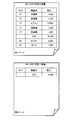
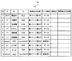
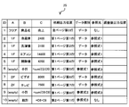
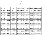
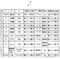
- FIG. 3 is an example of an initial output layout of a form in the first embodiment.
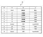
- FIG. 2 is an example of in-form data of the form shown in FIG. 1 in the first embodiment.
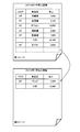
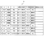
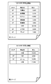
- it is an example of form output after adjusting the output position of a record.
- 1 is a block diagram schematically showing the configuration of a form data output system in a first embodiment.
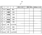
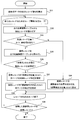
- FIG. 5 is a diagram illustrating an example of an output position adjustment table in the first embodiment. 5 is a flowchart showing a flow of processing in an output data analysis program in the first embodiment. In 1st Embodiment, it is a figure which shows an example of the output position adjustment table after completion
- 5 is a flowchart illustrating a processing flow of a reference destination data analysis program in the first embodiment.
- 1st Embodiment it is a figure which shows an example of the output position adjustment table after the completion
- 5 is a flowchart illustrating a processing flow of an output position adjustment program in the first embodiment.
- 1st Embodiment it is a figure which shows an example of the output position adjustment table after the completion
- 4 is a flowchart showing a flow of processing in an output program in the first embodiment.
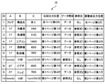
- a 2nd embodiment it is an example of the initial output layout of a form.
- 2nd Embodiment it is an example of the data in the form of the form shown in FIG.
- 2nd Embodiment it is an example of the form output after adjusting the output position of a record.
- 2nd Embodiment it is a figure which shows an example of the output position adjustment table after the completion
- 2nd Embodiment it is a figure which shows an example of the output position adjustment table after completion
- 3rd Embodiment it is an example of the output initial layout of a form.
- 3rd Embodiment it is an example of the form output after adjusting the output position of a record.
- 3rd Embodiment it is a figure which shows an example of the output position adjustment table after the completion
- 4th Embodiment it is a figure which shows an example of the output position adjustment table after the completion
- 14 is a flowchart illustrating a processing flow of an output position adjustment program in the fourth embodiment.
- a 5th embodiment it is an example of form output after adjusting the output position of a record.
- it is a flowchart which shows the flow of a process of an output position adjustment program.
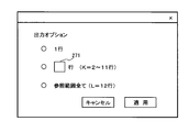
- it is a figure which shows typically the setting screen in which a user designates the number of movement records.
- it is a flowchart which shows the flow of a process corresponding to designation
- it is a flowchart which shows the flow of a process by an output analysis program.
- the embodiment of the present invention is characterized by adjusting the record output position in the form data output.
- predetermined multiple records are output on the same page.
- the output position of the record in the form is determined, and the page of the reference record including the reference expression and the page of one or a plurality of reference destination records (referenced records) defined for the reference record are specified.
- the form data output system of this embodiment determines the initial output layout of the form, and then adjusts the layout as necessary. Specifically, when a record (reference record) that includes a reference expression in the determined output layout is output at the top record position of the page, the record immediately before the reference expression refers to is the same as the next page, that is, the reference record Go to the page.
- FIG. 1 shows an example of a layout before adjustment in the present embodiment.
- FIG. 1 is an example of a form of sales results for July 2010, and is composed of two pages. This form includes a title and a table.
- a record is a line that includes actual data of a user and whose output position is variable.
- the first line of the first page and the second page is an item name line, and is fixed at the position of the first line of each page. These fixed lines are excluded from the record whose position is to be adjusted.
- each cell “32,100” in the sixth record (seventh row) of the table on the first page and “15,500” in the first record (second row) on the second page contains a reference formula (reference cell). Accordingly, each of the sixth record on the first page and the first record on the second page is a reference record.
- Fig. 2 shows the data used by the form shown in Fig. 1 in a table format.
- the 6th record on the first page in FIG. 1 shows a subtotal of product sales on the 1st floor.
- the cell “32, 100” is the sum of the values of the last five cells (from the first to the fifth records) in the same column, and refers to these cells.
- the first record on the second page in FIG. 1 shows a subtotal of product sales on the 2nd floor.
- the cell of “15,500” in the record is the value of the cell in the previous two (seventh record and eighth record on the first page) in the same column (“sales” column). , Which refers to those cells.
- the “subtotal” record on the 2nd floor is output at the top record position (the top position in the record) of the second page.
- the other two records indicating the sales of the 2nd floor are output on the first page.
- the “TV” record immediately before the “subtotal” record on the 2nd floor is a record to be referred to, and is displayed on the first page.
- the form data output system adjusts the form output layout shown in FIG. 1 and changes the layout shown in FIG. 1 to the layout shown in FIG. In FIG. 3, the second page displays two records. One is a TV sales record on the 2nd floor, and the other is a sales subtotal record on the 2nd floor.
- This system moves the output position of the TV sales record on the 2nd floor from the end of the first page to the top position of the second page (the top position in the record). Furthermore, with the movement, the output position of the subtotal sales record on the 2nd floor is shifted to the second position on the second page.
- the second page displays the records that the record references in addition to the sales subtotal record on the 2nd floor, so that the user can only view the second page and the record containing the “subtotal” cell will be displayed on the 2nd floor. You can easily understand that it is a subtotal sales record.
- FIG. 4 is a block diagram schematically showing the configuration of the form data output system 1 of the present embodiment.
- the form data output system 1 includes a computer 11 which is a form data processing apparatus and a program executed on the computer.
- the computer 11 includes a display interface 111, a printer interface 112, an input device interface 113, a CPU 114, a bus 115, a main storage device 116, a secondary storage device 117, and a network interface 118.
- the display 12 is connected to the display interface 111, and the printer 13 is connected to the printer interface 112.
- An input device 14 such as a mouse or a keyboard is connected to the input device interface 113.
- the user can input data using the input device 14.
- the computer 11 can output the form to the display 12 and the printer 13.
- the form data output system 1 may have only one of the display 12 and the printer 13.
- the computer 11 is connected to the network via the network interface 118.
- the user may access the form data output system 1 from another terminal connected to the network and use the function.
- the computer 11 may output the form to an output device such as a display or a printer connected via a network.
- Some of the processing executed by the computer 11 described below may be performed by another computer.
- a plurality of computers are form data processing devices.
- the CPU 114 is a processor that realizes a predetermined function of the form data output system 1 by executing a program stored in the main storage device 116.
- the bus 115 is a communication path that connects the devices of the computer 11 so that they can communicate with each other.
- the main storage device 116 is a storage device that stores a program executed by the CPU 102 and data necessary for executing the program, and is typically a RAM (Random Access Memory) that is a volatile semiconductor memory.
- the secondary storage device 117 is a storage device having a nonvolatile storage medium, and is a program (for example, a program stored in the main storage device 116 in FIG. 4) required to realize a predetermined function of the form data output system 1. ) And data.
- a hard disk including a magnetic disk and a storage device including a nonvolatile semiconductor storage medium such as a flash memory may be used.
- the main storage device 116, the secondary storage device 117, and the set thereof are storage devices.
- the program executed by the computer 11 and data to be processed may be stored in an external data storage device connected via a network.
- the computer 11 acquires necessary data (including a program) from the data storage device via the network.
- FIG. 4 shows the programs 21 to 24 and the output position adjustment table 25 in the main storage device 116 for convenience, and the form data 26 and the form definition file 27 in the secondary storage device 117.
- Data required in the processing of the computer 11 is typically loaded from the secondary storage device 117 to the main storage device 116.
- Each piece of information (representing data) is stored in the respective storage areas in the main storage device 116 and the secondary storage device 117.
- the CPU 114 executes an output data analysis program 21, a reference data analysis program 22, an output position adjustment program 23, and an output program 24.
- the CPU 114 functions as an output data analysis unit, a reference destination data analysis unit, an output position adjustment unit, and an output unit by operating according to these programs. Therefore, in the following description, the description with the program as the subject may be the description with the CPU 114 as the subject.
- the process executed by the program is a process performed by the computer 11 on which the program operates.
- the output position adjustment table 25 is a table that holds the record contents in the form, the output position of the record in the form, and the like, and is used in the adjustment of the record output position (adjustment of the form layout). The adjustment of the record output position will be described later.
- the in-form data 26 includes user data displayed on the form, and is used in the form output.
- FIG. 2 shows an example of the form data.
- the form definition file 27 includes data that defines the layout of the form and holds information that does not depend on the user.
- the information stored in the data storage area does not depend on the data structure, and may be expressed in any data structure.
- a data structure appropriately selected from a table, list or data base can store the information.
- the in-form data 26 and the form definition file 27 may be included in one file.
- the output position adjustment table 25 may be divided into a plurality of tables instead of a single table.
- the present embodiment determines the initial layout of the form, that is, the initial output position of the record in the form, and adjusts the record output position when the reference record is at the top record position.
- each program 21 to 24 will be described below with reference to an example of processing for outputting the form shown in FIG. 3 from the in-form data 26 shown in FIG. FIG. 5 is an output position adjustment table 25 generated from the in-form data shown in FIG.
- the output data analysis program 21 generates an output position adjustment table 25 shown in FIG.
- the output position adjustment table 25 stores the data of the in-form data 26 shown in FIG. Specifically, column A stores floor information for each record, column B stores product name information for each record, and column C stores sales information for each record. In column B, two cells indicate “subtotal”, and cells in column C of those records indicate subtotal values.
- the column “ID” stores a row number which is a row identifier. The contents of the in-form data 26 are as described above with reference to FIG.
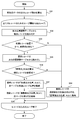
- FIG. 6 is a flowchart showing the processing of the output data analysis program 21, and FIG. 7 is an example of the output position adjustment table 25 as a processing result of the output data analysis program 21.
- the output data analysis program 21 analyzes the data in the output position adjustment table 25 shown in FIG. 5 and stores the analysis result in the output position adjustment table 25. Specifically, the analysis result data is stored in the initial output position column and the data type column.
- the output data analysis program 21 calculates the number N of output rows of tabular data (S11).
- the output line includes a line of only the item name whose output position is fixed.
- the output data analysis program 21 repeats the processing from step 12 to step 15 N times with the initial value of the variable i being 1.
- N is the number of lines in the form, and is 10 in this example shown in FIG.
- the output data analysis program 21 calculates the output data position of the k-th row (k is an integer from 1 to N), and calculates the value as “k” of the k-th row in the output position adjustment table 25. Store in the cell of “initial output position”.
- the output data analysis program 21 determines whether or not the kth row includes a reference cell (S13). When the reference cell is not included, the output data analysis program 21 records “data” in the “data type” cell of the row (S14). When the reference cell is included, the output data analysis program 21 stores “reference expression i” in the cell of “data type” and increments i (S15).
- the output position adjustment table 25 stores the data shown in FIG. In FIG. 7, the output position adjustment table 25 stores data in cells of all rows in the columns of “initial output position” and “data type”.
- the layout of the form according to the value of “initial output position” in the output position data table 25 shown in FIG. 7 is the layout shown in FIG.
- the row of the item name of row ID 1 is displayed at the top position (0th row) of each page, and is output on the 0th row of the first page and the second page in this example.
- the initial output position of the records with the row IDs 2 to 9 is the first page, and the initial output position of the record with the row ID 10 is the second page.
- “data type” is “reference formula 1” and “reference formula 2”.
- the “sales” cell in the record of the row ID 7 is the sum of the cells C2 to C6, and refers to the cells C2 to C6.
- the “sales” cell in the record of the row ID 10 is the sum of the cells C8 and C9, and refers to the cells C8 and C9.
- the “data type” of the other record and item name rows is “data” because it does not include cells that refer to other rows.
- the output data program 21 calculates the output data position of each row of the tabular data and stores it in the “initial output position” column of the output position adjustment table 25. Further, it is determined whether each row includes a reference expression. If the row includes a reference expression, “reference expression i” is stored in the “data type” cell of the row. On the other hand, when the row does not include the reference expression, “data” is stored in the “data type” cell of the row.
- the reference data analysis program 22 analyzes the output position adjustment table 25 shown in FIG. 7 and stores the analysis result in the output position adjustment table 25.
- An output position adjustment table 25 in which the reference destination data analysis program 22 stores analysis result data is shown in FIG. This process by the reference data analysis program 22 will be described with reference to the flowchart of FIG.
- the reference destination data analysis program 22 initializes the cells in the “reference source” column to “none” in all the rows of the output position adjustment table 25 (S21).
- the reference cell is a cell (referenced cell) that is referred to
- the “reference source” is a reference expression that refers to the referenced cell. Thereafter, the reference destination data analysis program 22 executes steps 22 to 24 for each reference expression.
- the reference destination data analysis program 22 executes steps 22 to 24 for each of the reference expression 1 and the reference expression 2. In each cycle of the reference expression 1 and the reference expression 2, steps 23 and 24 are executed for each reference destination cell. Since the reference formula 1 refers to five cells, the reference data analysis program 22 executes steps 23 and 24 five times in the cycle of the reference formula 1. Reference formula 2 is executed twice.
- the reference destination data analysis program 22 reads one record whose “data type” is a reference expression in the output position adjustment table 25.
- the record (row ID 7) of reference formula 1 is read.
- a reference destination cell that is, one record including the cell referred to in the reference formula 1 is read.
- the output position adjustment table 25 is read from the upper record, and in this example, the record of the row ID 2 is read first.
- the “reference source” cell in the record is updated from “none” to “reference expression 1”.
- the reference data analysis program 22 executes step 23 and step 24 for each record of line numbers 3-6. As shown in FIG. 9, the “reference source” cell in each record is updated from “none” to “reference formula 1”.
- the reference data analysis program 22 returns to step 22 and reads the next record whose “data type” is a reference expression in the output position adjustment table 25.
- the record of the reference formula 2 (row ID 10) is read.
- a reference destination cell that is, one record including the cell referred to in the reference formula 2 is read.
- the record with the row ID 8 is read first.
- the “reference source” cell in the record is updated from “none” to “reference expression 2”.
- the reference destination data analysis program 22 executes Step 23 and Step 24 for the record with the row ID 9 as well. As shown in FIG. 9, the “reference source” cell in the record is updated from “none” to “reference formula 2”. When step 22 to step 24 are executed for all reference records (records including reference cells), the reference destination data analysis program 22 ends this processing. In the example of FIG. 7, when step 22 to step 24 are executed for the record of reference expression 1 and the record of reference expression 2, this process is terminated.
- the output position adjustment table 25 changes from the state shown in FIG. 7 to the state shown in FIG. 9 by the processing of the reference destination data analysis program 22 shown in FIG. In FIG. 9, each cell in the “reference source” column of the output position adjustment table 25 stores one of the initial values “none”, “reference expression 1”, or “reference expression 2”. .
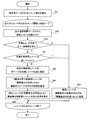
- FIG. 10 is a flowchart showing the flow of processing by the output position adjustment program 23.
- the output position adjustment program 23 stores a value in the “adjusted output position” column in the output position adjustment table 25 shown in FIG.
- the output position adjustment table 25 after the end of the processing of the output position adjustment program 23 is shown in FIG.
- the output position adjustment program 23 determines whether or not the record whose “data type” cell value is “reference expression i” is at the top record position of the page, and is at the top record position of the page. , It is determined whether the immediately preceding record is the reference destination of the reference expression. If it is a reference destination, the output positions of the immediately preceding record and the corresponding record are corrected from the value of “initial output position”, and the corrected value is stored in the cell of “adjusted output position”.
- the processing of the output position adjustment program 23 will be described with reference to the flowchart of FIG.
- the output position adjustment program 23 sets the adjusted output position.
- the output position adjustment program 23 calculates the number M of output records of the tabular data (see FIG. 2) of the form (S31). In this example, the number of output records is nine.
- the output position adjustment program 23 executes steps 32 to 38 for each of the M records.
- the output position adjustment program 23 reads a record (current record) from the output position adjustment table 25 (S32). The output position adjustment program 23 sequentially reads records from the upper side of the table. The output position adjustment program 23 determines whether the initial output position of the current record is the top record position of the page (first line in the example of FIG. 11) and includes a reference expression (S33).
- the “output position adjustment program 23 stores the next position of the“ adjusted output position ”of the previous record in the“ adjusted output position ”cell (S34).
- the output position adjustment program 23 stores the initial position in the “adjusted output position” cell.
- the output position adjustment program 23 reads the data of the immediately preceding record from the output adjustment table 25 (S35), and the value of the “reference source” cell of the immediately preceding record is the reference expression of the current record. It is determined whether there is (S36). If it is not the reference formula of the current record, step 34 is executed.
- the output position adjustment program 23 puts the value of the “initial output position” cell next to the “adjusted output position” cell of the previous record.
- the first record position of the page is stored (S37). Further, the next record position of the immediately preceding record, that is, the second record position of the same page is stored in the “adjusted output position” cell of the current record (S38).
- the initial position of the record (line number 10) of the reference formula 2 is the first line (first position) of the second page (see FIG. 1).
- the record immediately before that (line number 9) is referred to by the reference expression 2. Therefore, the output position adjustment program 23 writes the second page and the first row in the “adjusted output position” cell of the record of the row number 9, and the second in the “adjusted output position” cell of the record of the row number 10. Write the second line of the page.
- the adjusted form layout is as shown in FIG. 2, and the 2F TV record is printed on the second page together with the 2F subtotal record.
- the output program 24 outputs the data of each line (including the line of the item name) to the form according to the “adjusted output position” in the output position adjustment table 25.
- the output program 24 calculates the number N of lines of the notation data (S41), reads the data of each line (S42), and according to the “adjusted output position” in the output position adjustment table 25, the data of each line (the line of the item name) (Including) is output to the form (S43).
- the printing result according to the example of FIG. 11 is shown in FIG. In this example, the number of lines is 10, and the line of the item name of line number 1 is printed twice.
- the record to be referenced can be displayed together with the record including the reference expression on the same page, so that the user can easily recognize the meaning of the reference record.
- the record of “2F / TV” is output to the second page, so that the meaning of “subtotal” on the second page can be easily recognized.
- the change from the normal form layout (the layout based on the initial position) is small from the viewpoint of the visibility of the form by the user.
- the adjustment of the record output position of this embodiment a specific record is moved to the next page, and the subsequent record positions are shifted accordingly. For this reason, the output order of records can be made the same as that of the normal layout (initial layout) before adjustment, and a reduction in visibility can be avoided. Further, in the present embodiment, since it is specified that only the last referenced record is output to the same page as the reference record, the change from the initial layout can be particularly reduced.
- the program can be installed in the computer 1 from a program distribution server or a computer-readable non-volatile storage medium, and can be stored in a non-volatile medium in the secondary storage device 117 of the computer 1. it can.
- a part of the program may be realized by dedicated hardware.
- the form data output system 1 may use the same processing method or a different processing method for outputting a form to a display and outputting a form to a printer.
- the record output position may be adjusted for output to either the display or the printer, or the record output position is not adjusted for output to the display, and the output position is adjusted only for output to the printer. May be.
- FIG. 13 shows an initial layout based on the form data in this embodiment.
- the top record of the second page is a “total” record.
- the immediately preceding record is a “subtotal” record and is displayed at the last record position of the first page.
- FIG. 14 shows in-form data 26 of the form in FIG. As shown in FIG. 14, “total” represents the sum of a subtotal of 1F and a subtotal of 2F.
- FIG. 15 shows an output result after adjusting the output position of the present embodiment.
- the “2F / TV” record on the first page and the “subtotal” record have moved to the second page.
- the “total” record refers to the “subtotal” record
- the “subtotal” record refers to the “2F / TV” record.
- the “2F / TV” record does not include a reference expression.
- FIG. 16 shows an output position adjustment table 25 as a processing result of the reference destination data analysis program 22, and corresponds to the output position adjustment table 25 shown in FIG.
- a “total” record is added.
- the value of the “data type” cell in the “total” record is the reference expression 3.
- the value of the “reference source” cell of the two subtotal records is “reference expression 3”. That is, the two “subtotal” records are referred to by the reference expression 3 of the “total” record.
- the two “subtotal” records are reference records and referenced records.
- the output position adjustment program 23 refers to the output position adjustment table 25 shown in FIG. 16 and sets a value in each cell of “adjusted output position”.
- FIG. 17 shows a setting result by the output position adjustment program 23. As shown in the “adjusted output position” column in the output position adjustment table of FIG. 17, the records “2F / TV”, “subtotal”, and “total” are adjusted to be output on the second page.
- FIG. 18 is a flowchart showing the processing of the output position adjustment program 23 in the present embodiment.
- Step 39 is added to the processing steps in the first embodiment shown in FIG.
- Step 39 determines whether or not the moved referenced record is a reference record after the repetition process is completed. If the record moved to the next page is a reference record by this step 39, the referenced record immediately before is also moved to the next page. As long as the record moved by the output position adjustment program 23 is a reference record, the processing from step 32 is repeated.
- the referenced record immediately before the first record in the initial layout refers to further includes a reference expression
- the referenced record being referred to is added to the plurality of reference records.
- This embodiment does not change the record output order from the initial position in the adjustment of the output position, as in the first embodiment. Further, only one referenced record moves. Therefore, it is possible to easily recognize the meaning of the reference record while reducing the change from the normal layout.
- the reference cells of the first and second embodiments refer to other cells in the calculation formula.
- the reference cell may refer to another cell in a manner different from the calculation formula.
- a reference cell refers to another cell in a comment sentence.
- FIG. 19 shows an initial layout of the form in the present embodiment.
- the first record on the second page is a comment sentence of the record “2F / TV” on the first page, and is a record associated with the comment sentence.
- the comment text is output at the top record position of the second page, it is difficult for the user to recognize what the comment text is.
- FIG. 20 shows a form layout in which the output position of this embodiment is adjusted.
- the first page is output in the initial layout, and the record “2F / TV” referenced in the comment record on the second page is displayed as the first record on the second page.
- the comment record and the “subtotal” record shift downward.
- FIG. 21 shows the position adjustment table 25 in which data is set in all the cells including the column “adjusted output position”.
- the output data analysis program 21 refers to the cell in column C of the record with the row ID 10 and sets “reference expression 2” to the cell of “data type” in the record.
- the reference destination data analysis program 22 refers to the cell in column C, and sets “reference expression 2 and reference expression 3” in the “reference source” cell in the record of row number 9. This is because the record “2F / TV” is referenced by both the 2F subtotal record (line ID 11) and the comment record (line ID 10).
- the output position adjustment program 23 determines the value of each cell of “adjusted output position” according to the flowchart of FIG. 10 described in the first embodiment, and writes the value in the output position adjustment table 25.
- the adjusted output position of the record of “2F / TV” is the first line of the second page, and the output position of the comment record and the subtotal record is one line according to the movement of this record. Shift one by one.
- the comment sentence “including a TV with a moving image recording function” is a reference record that refers to a record of “2F / TV”, and “2F / TV” that is a reference destination is referred to.
- the reference record when the reference record is the top record of the page and the record immediately before the reference record is the referenced record, the referenced record is output to the same page as the reference record.
- the reference record refers to the immediately preceding record. Therefore, in most forms, the records linked by reference can be displayed on the same page by the method of the above embodiment, and only the reference record is displayed without displaying the referenced record on a specific page. Can be avoided. Further, according to the above embodiment, a large change from the normal layout can be avoided.
- the referenced record even if the layout is largely changed, it may be preferable to display the referenced record at a position away from the reference record on the same page as the reference record.
- the referenced record when only the reference record is in the page in the initial layout, a configuration in which the referenced record can be output to the same page as the reference record even when the immediately preceding record is not the referenced record will be described.
- FIG. 22 shows an example of the output position adjustment table 25 in the present embodiment.
- the initial layout and the adjusted layout of the form corresponding to the output table 25 are the same as those in the third embodiment.
- the output position adjustment table 25 shown in FIG. 22 has a comment record with a line number 10 as in the output position adjustment table 25 shown in FIG. 20 in the third embodiment.
- the comment record does not refer to any record and is a non-reference record. Therefore, the “data type” of the “subtotal” record of line number 11 is “reference formula 2”. Further, the reference source of the “2F / TV” record of line number 9 is only “reference expression 2”. Similar to the above embodiment, the output data analysis program 21 and the reference data analysis program 22 set these values.
- the initial layout of the output position adjustment table 25 shown in FIG. 22 is the same as the form layout shown in FIG.
- the first record on the second page is a comment record, not a reference record. Also, all the referenced records of the “subtotal” record (record with row ID 11) on the second page are on the first page and are not output on the second page.
- the output position adjustment program 23 changes the output position of the record “2F / TV”, which is the last reference record of the “subtotal” record, to the first record position of the second page, and accordingly, Shifts the output position of subsequent records backward. As a result, the form shown in FIG. 20 is output.
- FIG. 23 is a flowchart showing a processing flow of the output position adjustment program 23 in the present embodiment.
- the output position adjustment program 23 sets the value of the “initial output position” cell in the “adjusted output position” cell in all rows (S51).
- the number N of records of the tabular data of the form is calculated (10 in the example in the figure) (S52), and Steps 53 to 57 are executed for each record. Steps 53 to 57 are sequentially executed from the record of the row ID2.
- a value indicating “0th row of all pages” which is a specified value is stored.
- the output position adjustment program 23 reads the current record (S53), the read current record is a reference record, and the value of the “adjusted output position” cell of the last referenced record is “adjustment” of the current record. It is determined whether or not the same page as the value of the “post output position” cell is indicated (S54). If they are in the same page (Y in S54), the position after the adjusted output position of the previous record is set in the “adjusted output position” cell (S55), and the process proceeds to the next record.
- the output position adjustment program 23 updates the value of the “adjusted output position” cell of the last referenced record and sets the start position of the next page (S56). . Further, in accordance with the change, the value of the “adjusted output position” cell of the record after that record is updated (S57). Specifically, the output positions of the records after the last referenced record are shifted backward without changing the order of the records.
- the output position adjustment program 23 executes step 53 to step 57 for all the records, the process is terminated.
- the output position adjustment program 23 may change the output position of the referenced record when a predetermined condition is satisfied.
- the output position adjustment program 23 changes the position of the last referenced record when the reference record is the top position of the page as in the first to third embodiments.
- the output position adjustment program 23 may use as a condition that the distance between the reference record and the referenced record is within a specified range (typically within the specified number of records). For example, when the condition is that the distance between the reference record and the last referenced record is within one record, the condition is that the last referenced record is the immediately preceding record.
- System 1 can set one or both of these two conditions. For example, when the specified number of records in the reference record condition is 0 and the distance in the condition of the last referenced record is 1, the processing of this embodiment is the same as in Embodiments 1 and 3.
- the system 1 may be configured so that the user can specify these condition values.
- the output position adjustment program 23 moves the last referenced record to the top position of the next page. As a result, the amount of change of other records can be reduced, but depending on the design, it may be moved to a position after the head position.
- FIG. 24 is an example of the initial layout of a form.
- a sales record of 3F products and a subtotal record thereof are added to the example of the form described in FIG.
- 2F subtotal records are displayed at the top of the second page, and all other records on 2F are displayed on the first page. For this reason, it is difficult to recognize the meaning of this 2F subtotal record.
- FIG. 25 shows the final form output result obtained by the processing of this embodiment.
- this embodiment moves all the referenced records (all 2F product sales records in this example) of the reference record (2F subtotal record in this example) to the next page, and outputs them to the same page. .
- FIG. 26 is a flowchart showing a processing flow of the output position adjustment program 23 in the present embodiment. Steps S31 to S34 are the same as the flowchart of FIG. 18 in the second embodiment, and a description thereof will be omitted.
- the output position adjustment program 23 determines whether or not the first referenced record (“video” record in the example of FIG. 25) is on the same page as the reference record (S61). If the determination result is YES, the process proceeds to step S34.
- the output position adjustment program 23 sets the head position of the next page in the “adjusted output position” cell of the head reference record (S62), and further references thereafter.
- the next position of the immediately preceding record is set in the “adjusted output position” cell of the record (“TV” record in the example of FIG. 25) (S63).
- the output position adjustment program 23 sets the next position of the last referenced record (“TV” record in the example of FIG. 25) in the “adjusted output position” cell of the reference record (64). .
- the loop is repeated for records below this reference record.
- all the records referenced by the reference record can be output on the same page as the reference record.
- the number of referenced records to be moved is set in advance.
- the form data output system 1 can move a plurality of referenced records as in the fifth embodiment, if the user can specify the number of records to be moved, the convenience for the user is enhanced.
- FIG. 27 schematically shows a setting screen for the user to specify the number of moving records.
- the user specifies the number of referenced records to be moved to the next page. If the specified number of records is one line, the processing result is the same as in the first embodiment.
- the user can specify the number of moving records in the setting field 271. It is a record that the referenced record specified by the user is specified to be output on the same page as the reference record.
- any value from 2 to 11 rows can be set, and is limited to less than the total number of referenced records (L rows).
- the total number of referenced records is 12 lines.
- FIG. 28 is a flowchart showing a flow of processing corresponding to designation by the user.
- the user-specified number is stored in the main storage device 12.
- the output position adjustment program 23 performs the processing of FIG. 28 with reference to the designated number. Specifically, the output position adjustment program 23 determines whether the designated number is one line (Y in S71), the total number of records (Y in S72), or the other number of lines (S71 and S72). N). Further, the determination result is substituted into the variable R (S73 to S75).
- the output position adjustment program 23 executes step 76 for the number of rows (R) of the designated record, and moves the referenced record to the next page.
- step 76 the output position adjustment program 23 sets the output position of the next page in the “adjusted output position” cell in each of the number of referenced records specified from the last referenced record.
- the first record position of the next page is set as the output position of the first referenced record, and the next position of the immediately preceding record is set as the output position of the referenced record thereafter.
- the output position of subsequent records is shifted backward (downward).
- the reference ranges (rows of reference cells) of different reference cells are the same.
- a preferred example is to adjust the output position of the referenced record when multiple reference cells refer to the same range, and to adjust when they are different. Not performed.
- FIG. 29 is a flowchart showing the flow of this processing by the output analysis program 21.
- the output analysis program 21 is similar to the flowchart shown in FIG. 6 in S11 to S15 in the flowchart shown in FIG.
- the output analysis program 21 determines the number of reference cells (S81). If the number is 1, the process proceeds to step 15.
- the reference range of the reference expression is determined (S82). If the reference range of any reference expression is different from other reference expressions, data is set in the “data type” of the record (S14). If all the reference ranges are the same, the process proceeds to step 15. By adjusting the layout only when the reference range is the same, the probability of occurrence of display problems due to the adjustment in a rare case is reduced.
- the output order of records may be changed by design.
- they may not include the last referenced record.
- the referenced record in the page before the page immediately before the reference record may be moved so that the user can arbitrarily select the referenced record to be moved.
- a record includes a plurality of cells, but the number of cells included in the record is not particularly limited.
- the present invention can be applied to a form data output system.
Landscapes
- Engineering & Computer Science (AREA)
- Theoretical Computer Science (AREA)
- Health & Medical Sciences (AREA)
- Artificial Intelligence (AREA)
- Audiology, Speech & Language Pathology (AREA)
- Computational Linguistics (AREA)
- General Health & Medical Sciences (AREA)
- Physics & Mathematics (AREA)
- General Engineering & Computer Science (AREA)
- General Physics & Mathematics (AREA)
- User Interface Of Digital Computer (AREA)
Abstract
本発明の一実施形態の帳票データ出力システムは、帳票におけるレコードの出力位置を決定する。システムは、帳票における複数のレコードの初期出力位置を決定し、複数のレコードにおける参照レコード及びその参照レコードの出力ページを特定する。参照レコードと同一ページに出力されることが規定されている被参照レコードの初期出力位置が、参照レコードと異なるページにある場合、その被参照レコードの出力位置を、参照レコードと同一のページ内の位置に調整する。これにより、帳票の視認性を改善する。
Description
本発明は帳票におけるレコード出力位置の決定方法、帳票データ出力システム及びプログラムを記憶する計算機読み取り可能な記憶媒体に関し、特に、帳票出力におけるレコード位置の決定に関する。
業務や日常生活の様々な場面で帳票が用いられている。これらの帳票は、利用シーン毎に異なるものが使用される。そのため、多種多様な帳票を作成及び出力できる帳票データ出力システムの重要性は非常に高く、現在数多くの帳票データ出力システムが開発されている。
一部の帳票においては、その構成ページ数が、含まれるデータ量(レコード数)によって変化する。表示するレコードの数が多い場合、帳票は複数のページで構成される。例えば、店舗における月毎の売上実績の帳票には、各月に販売された商品及び金額の一覧が記載される。このような売上実績帳票のページ数は、記載される商品の数によって変化する。
複数ページの帳票レイアウトに対応する技術として、例えば、特許文献1は、自動レイアウトシステムによる複数ページのコンテンツの配置方法を開示している。特許文献1に記載の技術は、ページ内の空白領域の大きさやページに配置する項目の座標等を用いて、各ページの空白領域の大きさを均等にする。これにより、印刷結果の見栄えをよくすると共に、印刷コストを低減することを図る。
特許文献1に開示されている技術は、各ページの空白領域の大きさを均等にするため、空白領域とページに配置される項目との関連性を考慮する。しかし、ページに配置する項目間の意味の関連性を考慮していない。そのため、関連する項目が異なるページに印刷された場合に、特定の項目の意味が分かりづらくなることがある。
例えば、売上実績の帳票がフロア毎の小計値を表示する場合、特定フロアの小計値が、同一フロアの他の売上商品のレコードとは異なるページに記載されることがある(実施形態における図1を参照)。ユーザが小計値のみを表示するページを見た場合、その小計値が何の小計を意味するか(本例において特定フロアの小計を意味することを)認識することができない。
さらに、表示するデータの量は帳票ごとに異なる。例えば、上記売上実績の例において、帳票が表示するレコード数(データ量)は、月毎に異なる。そのため、帳票データ出力システムにおいて、予め「小計値だけのページを作らない」といった設定を、手動で行なうのは困難である。
そこで、本発明の一つの目的は、複数ページにわたる帳票を出力する際に、特定の関連するレコードを自動的に同一ページに配置することで、帳票における情報の視認性を高めることである。
本発明の一態様は、帳票データ出力システムにおいて帳票におけるレコードの出力位置を決定する方法である。この方法において、プロセッサが、初期データ記憶領域に格納されている前記帳票のユーザデータ及び前記帳票のレイアウトを規定するデータを使用して、前記帳票における複数のレコードの初期出力位置を決定する。前記プロセッサが、前記決定した初期出力位置を示すデータを初期出力位置記憶領域に格納する。前記プロセッサが、前記ユーザデータ及び前記初期出力位置データを使用して、前記複数のレコードにおける参照レコード及びその参照レコードの出力ページを特定する。前記プロセッサが、前記ユーザデータ及び前記レイアウトを規定するデータを使用して、前記参照レコードにより参照されており、初期出力位置が前記同一ページと異なるページにある、前記参照レコードと同一ページに出力されることが規定されている被参照レコードを特定する。前記プロセッサが、前記特定した被参照レコードの出力位置を、前記参照レコードと同一のページ内の位置に調整し、その調整後出力位置を調整後出力位置記憶領域に格納する。
本発明の一態様よれば、複数ページにわたる帳票を出力する際に、特定の関連するレコードを自動的に同一ページ内に配置することができ、帳票における情報の視認性を高めることができる。
以下、図面を参照しつつ、本発明を実施するための形態を説明する。説明の明確化のため、以下の記載及び図面は、適宜、省略及び簡略化がなされている。又、各図面において、同一要素には同一の符号が付されており、説明の明確化のため、必要に応じて重複説明は省略されている。
本発明の実施形態は、帳票データ出力におけるレコード出力位置の調整に特徴を有している。本実施形態は、所定の複数レコードを同一ページに出力する。具体的には、帳票におけるレコードの出力位置を決定し、参照式を含む参照レコードのページと、その参照レコードの規定の1つ又は複数の参照先レコード(被参照レコード)のページを特定する。
それらページが異なる場合には、帳票におけるレコード出力位置を調整し、上記規定の参照先レコードを、参照レコードと同一のページに移動する。このレコード位置調整によって、ユーザは参照レコードと参照先レコードを同一ページ上で見るので、参照レコードの意味を容易に認識することができる。
<第1の実施形態>
以下において、本発明の第1の実施形態を図1~図12を参照して説明する。本実施形態の帳票データ出力システムは、帳票の初期出力レイアウトを決定した後、必要に応じてそのレイアウトを調整する。具体的には、決定した出力レイアウトにおいて参照式を含むレコード(参照レコード)が、ページの先頭レコード位置に出力される場合、参照式が参照する直前のレコードを次のページ、つまり参照レコードと同一ページに移動する。
以下において、本発明の第1の実施形態を図1~図12を参照して説明する。本実施形態の帳票データ出力システムは、帳票の初期出力レイアウトを決定した後、必要に応じてそのレイアウトを調整する。具体的には、決定した出力レイアウトにおいて参照式を含むレコード(参照レコード)が、ページの先頭レコード位置に出力される場合、参照式が参照する直前のレコードを次のページ、つまり参照レコードと同一ページに移動する。
図1は、本実施形態における調整前のレイアウトの一例を示している。図1は、2010年7月の売上実績の帳票の例であり、2ページで構成されている。この帳票は、タイトル及び表を含む。本明細書において、レコードはユーザの実体的なデータを含み、出力位置が可変の行である。図1の例において、第1ページ及び第2ページの先頭行は、項目名の行であり、各ページの先頭行位置に固定されている。これら固定行は、位置調整の対象であるレコードから除く。
図1の例において、第1ページにおける表の6番目のレコード(7番目の行)における「32,100」のセル及び第2ページにおける1番目のレコード(2番目の行)における「15,500」のセルのそれぞれが、参照式を含む(参照セル)。従って、第1ページの6番目のレコード及び第2ページの1番目のレコードのそれぞれは、参照レコードである。
図2は、図1に示す帳票が使用するデータを表形式で表している。図1における第1ページ6番目のレコードは、1Fフロアの商品売上の小計を示している。図2に示すように、「32,100」のセルは、同一列における、直前5つ(1番目から5番目のレコード)のセルの値の和であり、それらセルを参照している。
図1における第2ページ1番目のレコードは、2Fフロアの商品売上の小計を示している。図2に示すように、そのレコードの「15,500」のセルは、同一列(「売上」列)における直前2つ(第1ページにおける7番目のレコード及び8番目のレコード)のセルの値の和であり、それらセルを参照している。
図1に示すレイアウトにおいて、2Fフロアの「小計」レコードは、第2ページの先頭レコード位置(レコードにおける先頭位置)に出力されている。2Fフロアの売上を示すその他の2つレコードは第1ページに出力されている。又、2Fフロアの「小計」レコードの直前の「テレビ」レコードは、このレコードの被参照レコードであり、第1ページに表示されている。
本形態の帳票データ出力システムは、図1に示す帳票出力レイアウトを調整し、図1のレイアウトから図3のレイアウトに変更する。図3において、第2ページは2つのレコードを表示している。一つは2Fフロアにおけるテレビの売上レコードであり、他の一つは2Fフロアの売上小計のレコードである。
本システムは、2Fフロアにおけるテレビの売上レコードの出力位置を、第1ページの最後尾から第2ページの先頭位置(レコードにおける先頭位置)に移動する。さらに、その移動に伴い、2Fフロアの売上小計レコードの出力位置を、第2ページの2番目の位置にシフトしている。第2ページは、2Fフロアの売上小計レコードに加え、そのレコードが参照しているレコードを表示しているので、ユーザが第2ページを見るだけで、「小計」セルを含むレコードが2Fフロアの売上小計レコードであることを容易に理解することができる。
次に、本実施形態の帳票データ出力システムの構成を説明する。図4は、本実施形態の帳票データ出力システム1の構成を模式的に示すブロック図である。帳票データ出力システム1は、帳票データ処理装置である計算機11及びその計算機上で実行されるプログラムを含む。計算機11は、ディスプレイインタフェース111、プリンタインターフェース112、入力デバイスインターフェース113、CPU114、バス115、主記憶デバイス116、二次記憶デバイス117、ネットワークインタフェース118を備える。
ディスプレイインタフェース111にディスプレイ12が接続され、プリンタインターフェース112にプリンタ13が接続されている。入力デバイスインターフェース113には、マウスやキーボードなどの入力デバイス14が接続されている。ユーザは、入力デバイス14によりデータを入力することができる。計算機11は、帳票をディスプレイ12及びプリンタ13に出力することができる。帳票データ出力システム1は、ディスプレイ12及びプリンタ13の一方のみを有していても良い。
計算機11は、ネットワークインタフェース118を介してネットワークと接続される。ユーザは、ネットワークに接続された他の端末から、帳票データ出力システム1にアクセスし、その機能を利用してもよい。また、計算機11は、ネットワークを介して接続されているディスプレイやプリンタなどの出力デバイスに、帳票を出力してもよい。以下において説明する計算機11が実行する処理の一部は他の計算機が行ってもよい。その構成において、複数の計算機が帳票データ処理装置である。
CPU114は、主記憶デバイス116に記憶されているプログラムを実行することによって帳票データ出力システム1の所定の機能を実現するプロセッサである。バス115は、計算機11のデバイスを相互に通信可能に接続する通信路である。主記憶デバイス116は、CPU102によって実行されるプログラム及びプログラムの実行に必要なデータを記憶する記憶デバイスであり、典型的には、揮発性の半導体メモリであるRAM(Random Access Memory)である。
二次記憶デバイス117は不揮発性記憶媒体を備える記憶デバイスであり、帳票データ出力システム1の所定の機能を実現するために必要なプログラム(例えば、図4において主記憶デバイス116に格納されているプログラム)及びデータを格納する。典型的には、磁気ディスクを備えるハードディスクであり、フラッシュメモリのような不揮発性の半導体記憶媒体を備える記憶デバイスを使用してもよい。主記憶デバイス116、二次記憶デバイス117及びこれらのセットは、記憶デバイスである。
計算機11が実行するプログラム及び処理するデータは、ネットワークを介して接続された外部のデータ記憶デバイスに格納されていてもよい。計算機11は、ネットワークを介してこのデータ記憶デバイスから、必要なデータ(プログラムを含む)を取得する。
図4は、便宜的に、プログラム21~24及び出力位置調整テーブル25を主記憶デバイス116内に図示し、帳票データ26及び帳票定義ファイル27を二次記憶デバイス117内に図示しているが、計算機11の処理において必要とされるデータは、典型的には、二次記憶デバイス117から主記憶デバイス116にロードされる。各情報(を表すデータ)は、主記憶デバイス116、二次記憶意装置117における、それぞれの記憶領域内に格納される。
図4に示すように、CPU114は、出力データ解析プログラム21、参照先データ解析プログラム22、出力位置調整プログラム23、出力プログラム24を実行する。CPU114は、これらのプログラムに従って動作することにより、出力データ解析部、参照先データ解析部、出力位置調整部、出力部として機能する。従って、以下において、プログラムを主語とする説明は、CPU114を主語とした説明でもよい。また、プログラムが実行する処理は、そのプログラムが動作する計算機11が行う処理である。
出力位置調整テーブル25は、帳票におけるレコードの内容や帳票におけるレコードの出力位置などを保持するテーブルであり、レコード出力位置の調整(帳票レイアウトの調整)において使用される。レコード出力位置の調整については後述する。帳票内データ26は、帳票が表示するユーザデータを含み、帳票出力において使用される。図2は帳票データの一例を示している。帳票定義ファイル27は、帳票のレイアウトを規定するデータを含み、ユーザに依存しない情報を保持している。
本実施形態において、データ記憶領域に格納される情報はデータ構造に依存せず、どのようなデータ構造で表現されていてもよい。例えば、テーブル、リスト若しくはデータ・ベースから適切に選択したデータ構造体が、情報を格納することができる。図4に示す本構成において、例えば、帳票内データ26及び帳票定義ファイル27は一つのファイルに含まれていてもよい。出力位置調整テーブル25は、一つのテーブルではなく、複数のテーブルに分割されていてもよい。
以下において、帳票内データ26及び帳票定義ファイル27から出力する帳票のデータを生成し、その出力を行う処理を説明する。上述のように、本実施形態は、帳票の初期レイアウト、つまり帳票におけるレコードの初期出力位置を決定し、参照レコードが先頭レコード位置にある場合に、レコード出力位置を調整する。
本実施形態の理解の容易のため、以下において、図2に示す帳票内データ26から図3に示す帳票を出力する処理の例を参照しつつ、各プログラム21~24の処理を説明する。図5は、図2に示す帳票内データから生成された出力位置調整テーブル25である。出力データ解析プログラム21は、図5に示す出力位置調整テーブル25を生成する。
図5において、出力位置調整テーブル25は、図2に示す帳票内データ26のデータを格納している。具体的には、A列が各レコードのフロアの情報を格納し、B列は各レコードの商品名の情報を格納し、そしてC列は各レコードの売上の情報を格納している。B列において、2つのセルは「小計」を示し、それらのレコードのC列のセルは小計の値を示している。「ID」の列は、行の識別子である行番号を格納している。帳票内データ26の内容については、図2を参照して行った上記説明の通りである。
図6は、出力データ解析プログラム21の処理を示すフローチャートであり、図7は、出力データ解析プログラム21の処理結果としての出力位置調整テーブル25の一例である。出力データ解析プログラム21は、図5に示す出力位置調整テーブル25のデータを解析し、出力位置調整テーブル25内にその解析結果を格納する。具体的には、初期出力位置の列とデータ種別の列に、解析結果のデータを格納する。
図6に示すように、出力データ解析プログラム21は、表形式データの出力行数Nを算出する(S11)。出力行は、出力位置が固定された項目名のみの行を含む。出力データ解析プログラム21は、ステップ12~ステップ15の処理を、変数iの初期値を1として、N回繰り返す。Nは帳票における行数であり、図5に示す本例において10である。ステップ12において、出力データ解析プログラム21は、k(kは1~Nのいずれかの整数)番目の行の出力データ位置を算出し、その値を出力位置調整テーブル25におけるk番目の行の「初期出力位置」のセルに格納する。
次に、出力データ解析プログラム21は、k番目の行が参照セルを含むか否かを判定する(S13)。参照セルを含まない場合、出力データ解析プログラム21は、その行の「データ種別」のセルに「データ」と記録する(S14)。参照セルを含む場合、出力データ解析プログラム21は、「データ種別」のセルに「参照式i」を格納し、iをインクリメントする(S15)。
出力データ解析プログラム21が全ての行に対して上記処理を行った後、出力位置調整テーブル25は、図7に示すデータを格納している。図7において、出力位置調整テーブル25は、「初期出力位置」及び「データ種別」の列において、全ての行のセルにデータを格納している。
図7に示す出力位置データテーブル25における「初期出力位置」の値に従う帳票のレイアウトは、図1に示すレイアウトである。図1に示すように、行ID1の項目名の行は、各ページの先頭位置(第0行)に表示され、本例においては第1ページと第2ページの0行目に出力される。行ID2~9のレコードの初期出力位置は第1ページであり、行ID10のレコードの初期出力位置は第2ページである。
行ID7及び行ID10の「小計」レコードにおいて、「データ種別」は「参照式1」及び「参照式2」である。行ID7のレコードにおける「売上」セルは、セルC2~セルC6の和であり、セルC2~セルC6を参照している。同様に、行ID10のレコードにおける「売上」セルは、セルC8、セルC9の和であり、セルC8、C9を参照している。その他のレコード及び項目名行の「データ種別」は、他の行を参照するセルを含まないため、「データ」である。
このように、出力データプログラム21は、表形式データの各行の出力データ位置を算出し、出力位置調整テーブル25の「初期出力位置」列に格納する。さらに、各行が参照式を含むかどうかを判定し、行が参照式を含む場合は、その行の「データ種別」のセルに、「参照式i」を格納する。一方、行が参照式を含まない場合は、その行の「データ種別」のセルに、「データ」を格納する。
次に、参照先データ解析プログラム22は、図7に示す出力位置調整テーブル25を解析し、出力位置調整テーブル25に解析結果を格納する。参照先データ解析プログラム22が解析結果のデータを格納した出力位置調整テーブル25を、図9に示す。図8のフローチャートを参照して、参照先データ解析プログラム22によるこの処理を説明する。
参照先データ解析プログラム22は、出力位置調整テーブル25の全ての行において、「参照元」列のセルを「なし」に初期化する(S21)。ここで、参照先セルは参照されているセル(被参照セル)であり、「参照元」は、被参照セルを参照している参照式である。その後、参照先データ解析プログラム22は、ステップ22~24を各参照式について実行する。
本例においては、参照先データ解析プログラム22は、参照式1及び参照式2のそれぞれについて、ステップ22~24を実行する。また、参照式1及び参照式2の各サイクルにおいて、各参照先セルについてステップ23及び24を実行する。参照式1は、5つのセルを参照しているので、参照先データ解析プログラム22は、参照式1のサイクルにおいて、ステップ23及び24を5回実行する。参照式2については、2回実行する。
ステップ22において、参照先データ解析プログラム22は、出力位置調整テーブル25において、「データ種別」が参照式である1つのレコードを読み出す。図7の例において、参照式1のレコード(行ID7)を読み出す。ステップ23において、参照先セル、つまり参照式1に参照されているセルを含む1つのレコードを読み出す。出力位置調整テーブル25は上側のレコードから読み出し、本例において、行ID2のレコードを最初に読み出す。ステップ24において、図9に示すように、そのレコードにおける「参照元」セルを、「なし」から「参照式1」に更新する。
参照先データ解析プログラム22は、行番号3~6の各レコードについても、ステップ23及びステップ24を実行する。図9に示すように、各レコードにおける「参照元」セルを、「なし」から「参照式1」に更新する。
次に、参照先データ解析プログラム22は、ステップ22に戻って、出力位置調整テーブル25において、「データ種別」が参照式である次のレコードを読み出す。本例において、参照式2のレコード(行ID10)を読み出す。ステップ23において、参照先セル、つまり参照式2に参照されているセルを含む1つのレコードを読み出す。本例において、行ID8のレコードを最初に読み出す。ステップ24において、図9に示すように、そのレコードにおける「参照元」セルを、「なし」から「参照式2」に更新する。
参照先データ解析プログラム22は、行ID9のレコードについても、ステップ23及びステップ24を実行する。図9に示すように、そのレコードにおける「参照元」セルを、「なし」から「参照式2」に更新する。全ての参照レコード(参照セルを含むレコード)についてステップ22~ステップ24を実行すると、参照先データ解析プログラム22は、本処理を終了する。図7の例においては、参照式1のレコードと参照式2のレコードについてステップ22~ステップ24を実行すると、本処理を終了する。
図8に示す参照先データ解析プログラム22の処理により、出力位置調整テーブル25は、図7に示す状態から図9に示す状態に変化する。図9において、出力位置調整テーブル25の「参照元」列の各セルには、初期値である「なし」、「参照式1」又は「参照式2」の値のいずれかが格納されている。
次に、出力位置調整プログラム23は、帳票における初期レイアウトを変更し、特定のレコードの出力位置を調整する。図10は、出力位置調整プログラム23による処理の流れを示すフローチャートである。本例において、出力位置調整プログラム23は、図9に示す出力位置調整テーブル25において、「調整後出力位置」列に値を格納する。出力位置調整プログラム23の処理終了後の出力位置調整テーブル25は、図11に示されている。
具体的には、出力位置調整プログラム23は、「データ種別」セルの値が「参照式i」であるレコードがページの先頭レコード位置にあるかどうかを判定し、ページの先頭レコード位置にある場合、直前レコードがその参照式の参照先であるかどうかを判定する。参照先である場合には、直前レコード及び該当レコードの出力位置を「初期出力位置」の値から修正し、修正した値を「調整後出力位置」のセルに格納する。
図10のフローチャートを参照して、出力位置調整プログラム23の処理を説明する。出力位置調整プログラム23は、調整後の出力位置を設定する。まず、出力位置調整プログラム23は、帳票の表形式データ(図2を参照)の出力レコード数Mを算出する(S31)。本例において、出力レコード数は9である。出力位置調整プログラム23は、ステップ32~38を、Mレコードのそれぞれについて実行する。
出力位置調整プログラム23は、出力位置調整テーブル25から、レコード(現在レコード)を読み出す(S32)。出力位置調整プログラム23は、表の上側から順次レコードを読み出す。出力位置調整プログラム23は、現在レコードの初期出力位置が、ページの先頭レコード位置(図11の例において第1行)でありかつ参照式を含むかを判定する(S33)。
判定結果がNOである場合、「出力位置調整プログラム23は、調整後の出力位置」のセルに、直前のレコードの「調整後出力位置」の次の位置を格納する(S34)。現在レコードが第1行のレコードの場合、出力位置調整プログラム23は、その初期位置を「調整後出力位置」のセルに格納する。
判定結果がYESである場合、出力位置調整プログラム23は、直前のレコードのデータを出力調整テーブル25から読み出し(S35)、その直前レコードの「参照元」セルの値が、現在レコードの参照式であるか判定する(S36)。現在レコードの参照式ではない場合、ステップ34を実行する。
直前レコードの「参照元」セルの値が、現在レコードの参照式である場合、出力位置調整プログラム23は、直前レコードの「調整後出力位置」セルに、「初期出力位置」セルの値の次のページの先頭レコード位置を格納する(S37)。さらに、現在レコードの「調整後出力位置」セルに、直前レコードの次のレコード位置、つまり、同一ページの2番目のレコード位置を格納する(S38)。
図11に示す出力位置調整テーブル25の例において、参照式2のレコード(行番号10)の初期位置が、第2ページの第1行(先頭位置)である(図1を参照)。また、その直前のレコード(行番号9)は、参照式2に参照されている。従って、出力位置調整プログラム23は、行番号9のレコードの「調整後出力位置」のセルに第2ページ第1行を書き込み、行番号10のレコードの「調整後出力位置」のセルに第2ページ第2行を書き込む。これにより、調整後の帳票レイアウトは図2に示す通りとなり、2F小計のレコードと共に、2Fテレビのレコードが第2ページに印刷される。
最後に、出力プログラム24の処理を、図12のフローチャートを参照して説明する。出力プログラム24は、出力位置調整テーブル25における「調整後出力位置」に従って、各行のデータ(項目名の行を含む)を帳票に出力する。出力プログラム24は表記式データの行数Nを算出し(S41)、各行のデータを読み出して(S42)、出力位置調整テーブル25における「調整後出力位置」に従って各行のデータ(項目名の行を含む)を帳票に出力する(S43)。図11の例に従う印刷結果は、図1に示されている。本例において、行数は10であり、行番号1の項目名の行は2回印刷される。
以上のように、本実施形態によれば、参照式を含むレコードと共にその被参照レコードを同一ページに表示することができるので、ユーザが参照レコードの意味を容易に認識することができる。被参照レコードを同一ページに表示することで、追加の情報を表示することなく、参照レコードの意味を適切に示すことができる。図3に示す例においては、「2F・テレビ」のレコードが第2ページに出力されることにより、第2ページの「小計」のの意味を容易に認識することができる。
レイアウト変更による新たな問題発生の蓋然性を小さくするためには、又、ユーザによる帳票の視認性の点から、通常の帳票レイアウト(初期位置によるレイアウト)からの変化は小さいことが好ましい。本実施形態のレコード出力位置の調整は、特定のレコードを次ページに移動し、それに合わせて、それ以降のレコード位置をずらしている。このため、レコードの出力順序を、調整前の通常レイアウト(初期レイアウト)と同じにすることができ、視認性の低下を避けることができる。さらに、本実施系形態においては、最後の被参照レコードのみが参照レコードと同一ページに出力されることが規定されているので、初期レイアウトからの変更を特に小さくすることができる。
なお、本実施形態において、プログラムは、プログラム配布サーバや、計算機読み取り可能な不揮発性記憶媒体から計算機1にインストールすることができ、計算機1の二次記憶デバイス117における不揮発性媒体に格納することができる。プログラムの一部は、専用ハードウェアによって実現されてもよい。
帳票データ出力システム1は、ディスプレイへの帳票出力とプリンタへの帳票出力において、同一の処理方法を使用してもよいし、異なる処理方法を使用してもよい。例えば、ディスプレイ及びプリンタのいずれに出力する場合でもレコード出力位置の調整を行なってもよいし、ディスプレイへの出力においてはレコード出力位置の調整を行なわず、プリンタへ出力においてのみ出力位置の調整を行ってもよい。プログラム及び出力方法に関するこれらの点は、以下に説明する他の実施形態において同様である。
<第2の実施形態>
以下において、第2の実施形態を図13~図18を参照して説明する。本実施形態のシステム構成は、第1の実施形態と同様である(図4を参照)。以下においては、主に、第1の実施形態と異なる点を説明する。第1の実施形態の例において、次ページに移動した「2F・テレビ」のレコードの「データ種別」は「データ」である。本実施形態においては、参照レコードの直前のレコードの「データ種別」が「参照式」である例を説明する。
以下において、第2の実施形態を図13~図18を参照して説明する。本実施形態のシステム構成は、第1の実施形態と同様である(図4を参照)。以下においては、主に、第1の実施形態と異なる点を説明する。第1の実施形態の例において、次ページに移動した「2F・テレビ」のレコードの「データ種別」は「データ」である。本実施形態においては、参照レコードの直前のレコードの「データ種別」が「参照式」である例を説明する。
図13は、本実施形態における帳票データによる初期レイアウトを示している。図13において、第2ページの先頭レコードは、「総計」のレコードである。直前のレコードは「小計」のレコードであり、第1ページの最後尾のレコード位置に表示されている。図14は、図13の帳票の帳票内データ26を示している。図14に示すように、「総計」は、1Fの小計と2Fの小計の和を表している。
図13の初期レイアウトにおいて、「総計」レコードだけが第2ページに出力されており、第2ページを見るだけではユーザにとって「総計」の意味の認識が困難である。図15は、本実施形態の出力位置の調整後の出力結果である。図15に示すように、第1ページの「2F・テレビ」のレコードと「小計」のレコードが、第2ページに移動している。「総計」レコードは、「小計」レコードを参照しており、さらに、「小計」レコードは「2F・テレビ」レコードを参照している。「2F・テレビ」レコードは参照式を含まない。
「小計」レコードと「総計」レコードとを同一ページに出力することで、ユーザは「総計」レコードの意味をある程度認識することができる。しかし、ユーザは、「小計」レコードの意味を正確に認識できず、「総計」レコードの意味も適切に認識することが難しい。本実施形態においては、「小計」レコードが参照する「2F・テレビ」レコードが、同一ページに表示されている。このため、ユーザは、「小計」レコード及び「総計」レコードの意味をより適切に認識することができる。
以下において、本実施形態の帳票データ出力処理の流れを説明する。出力データ解析プログラム21及び参照先データ解析プログラム22の処理は、図6及び図8を参照して説明した第1の実施形態と同様である。図16は、参照先データ解析プログラム22の処理結果としての出力位置調整テーブル25を示しており、図9に示す出力位置調整テーブル25に対応している。
図16に示すように、出力位置調整テーブル25において、「総計」のレコードが追加されている。「総計」レコードにおける「データ種別」セルの値は、参照式3である。2つの小計のレコードの「参照元」セルの値は、「参照式3」である。つまり、2つの「小計」レコードは、「総計」レコードの参照式3により参照されている。2つの「小計」レコードは、参照レコードであると共に被参照レコードである。
出力位置調整プログラム23は、図16に示す出力位置調整テーブル25を参照し、「調整後出力位置」の各セルに値を設定する。図17は、出力位置調整プログラム23による設定結果を示している。図17の出力位置調整テーブルにおける「調整後出力位置」列が示すように、「2F・テレビ」、「小計」、「総計」のレコードが、第2ページに出力されるよう調整されている。
図18は、本実施形態における出力位置調整プログラム23の処理を表すフローチャートである。図10に示す第1の実施形態における処理のステップに、ステップ39が追加されている。ステップ39は、繰り返し処理が終了した後に、移動した被参照レコードが参照レコードであるか否かを判定する。このステップ39により、次ページに移動したレコードが参照レコードである場合には、その直前の被参照レコードも次ページに移動される。出力位置調整プログラム23移動したレコードが参照レコードである限り、ステップ32からの処理を繰り返す。
以上のように、本実施形態によれば、初期レイアウトにおける先頭レコードが参照する直前の被参照レコードが、さらに参照式を含む場合に、複数の参照レコードに加え、参照されている被参照レコードを同一ページに表示することによって、ユーザが複数の参照レコードの意味をより容易に認識することができる。
本実施形態は、第1の実施形態と同様に、出力位置の調整においてレコード出力順序を初期位置から変更しない。また、移動する被参照レコードは一つのみである。そのため、通常レイアウトからの変更を小さくしつつ、参照レコードの意味を認識しやすくすることができる。
<第3の実施形態>
以下において、本発明の第3の実施形態を図19~図21を参照して説明する。上記第1及び第2の実施形態の参照セルは、計算式において他のセルを参照している。参照セルは、計算式と異なる態様により他のセルを参照してもよい。本実施形態において、計算式と異なる参照方法として、参照セルがコメント文において他のセルを参照する。このように、特定レコードが他のレコードと紐付いている場合、他のレコードを特定レコードと同一ページに表示することで、特定レコードの意味を認識しやすくすることができる。
以下において、本発明の第3の実施形態を図19~図21を参照して説明する。上記第1及び第2の実施形態の参照セルは、計算式において他のセルを参照している。参照セルは、計算式と異なる態様により他のセルを参照してもよい。本実施形態において、計算式と異なる参照方法として、参照セルがコメント文において他のセルを参照する。このように、特定レコードが他のレコードと紐付いている場合、他のレコードを特定レコードと同一ページに表示することで、特定レコードの意味を認識しやすくすることができる。
図19は、本実施形態における帳票の初期レイアウトを示している。第2ページの先頭レコードは、第1ページの「2F・テレビ」のレコードのコメント文であり、それに紐付くレコードである。しかし、コメント文が第2ページの先頭レコード位置に出力されているため、何に対するコメント文であるかをユーザが認識しづらい。
図20は、本実施形態の出力位置調整を行った帳票レイアウトを示している。初期レイアウトにおいて第1ページ出力されており、第2ページのコメントレコードに参照されている「2F・テレビ」のレコードが、第2ページの先頭レコードとして表示されている。又、「2F・テレビ」のレコードの移動に伴い、コメントレコードと「小計」レコードは下方にシフトしている。
図21は、「調整後出力位置」の列を含む全てのセルにデータが設定されている位置調整テーブル25を示している。コメントレコードは、行ID10のレコードであり、C列のセルの値(データ)は「ID=9のコメント」であり、「ID=9」という参照式により行ID9のレコードを参照している。
図21に示すように、出力データ解析プログラム21は、行ID10のレコードのC列のセルを参照して、そのレコードにおける「データ種別」のセルに、「参照式2」を設定する。参照先データ解析プログラム22は、C列のセルを参照し、行番号9のレコードにおいて、「参照元」セルに、「参照式2、参照式3」を設定する。「2F・テレビ」のレコードは、2Fの小計レコード(行ID11)及びコメントレコード(行ID10)の双方に参照されているからである。
出力位置調整プログラム23は、第1の実施形態において説明した図10のフローチャートに従って、「調整後出力位置」の各セルの値を決定し、その値を出力位置調整テーブル25に書き込む。図19を参照して説明したように、「2F・テレビ」のレコードの調整後出力位置は第2ページの第1行であり、このレコードの移動に従ってコメントレコードと小計レコードの出力位置が1行ずつシフトする。
このように、本実施形態においては、「動画像記録機能付テレビを含む」というコメント文が、「2F・テレビ」のレコードを参照する参照レコードであり、参照先である「2F・テレビ」をコメント文と同じページに出力することで、コメント文の意味をユーザが容易に認識することができる。
<第4の実施形態>
上記第1~第3の実施形態は、参照レコードがページの先頭レコードであり、参照レコードの直前のレコードがその被参照レコードである場合、その被参照レコードを参照レコードと同一ページに出力する。多くの帳票においては、参照レコードは直前のレコードを参照している。そのため、ほとんどの帳票において、上記実施形態の方法により、参照により紐付けられているレコードを同一ページに表示することができ、特定のページに被参照レコードが表示されることなく参照レコードのみが表示されることを避けることができる。又、上記実施形態によれば、通常レイアウトからの大きな変更を避けることができる。
上記第1~第3の実施形態は、参照レコードがページの先頭レコードであり、参照レコードの直前のレコードがその被参照レコードである場合、その被参照レコードを参照レコードと同一ページに出力する。多くの帳票においては、参照レコードは直前のレコードを参照している。そのため、ほとんどの帳票において、上記実施形態の方法により、参照により紐付けられているレコードを同一ページに表示することができ、特定のページに被参照レコードが表示されることなく参照レコードのみが表示されることを避けることができる。又、上記実施形態によれば、通常レイアウトからの大きな変更を避けることができる。
一方、レイアウトの変更が大きくとも、参照レコードから離れた位置の被参照レコードを参照レコードと同一ページに表示することが好ましい場合がある。本実施形態は、初期レイアウトにおいて参照レコードのみがページ内にある場合に、直前のレコードが被参照レコードでない場合でも、被参照レコードを参照レコードと同一ページに出力することができる構成を説明する。
図22は、本実施形態における出力位置調整テーブル25の一例を示している。この出力テーブル25に対応する帳票の初期レイアウト及び調整後レイアウトは、第3の実施形態と同様である。図22に示す出力位置調整テーブル25は、第3の実施形態における図20に示した出力位置調整テーブル25と同様に、行番号10のコメントレコードを有している。
第3の実施形態と異なり、コメントレコードはいずれのレコードも参照しておらず、非参照レコードである。そのため、行番号11の「小計」レコードの「データ種別」は「参照式2」である。又、行番号9の「2F・テレビ」レコードの参照元は、「参照式2」のみである。上記実施形態と同様に、出力データ解析プログラム21及び参照先データ解析プログラム22がこれらの値を設定する。
図22に示す出力位置調整テーブル25の初期レイアウトは、図19に示す帳票レイアウトと同様である。第2ページの先頭レコードはコメントレコードであり、参照レコードではない。また、第2ページの「小計」レコード(行ID11のレコード)の全ての被参照レコードは第1ページにあり、第2ページには出力されない。
本実施形態において、出力位置調整プログラム23は、「小計」レコードの最後の参照レコードである「2F・テレビ」のレコードの出力位置を、第2ページの先頭レコード位置に変更し、それに合わせて、それ以降のレコードの出力位置を後ろにシフトする。これにより、図20に示す帳票が出力される。
図23は、本実施形態における出力位置調整プログラム23の処理の流れを示すフローチャートである。出力位置調整プログラム23は、全ての行における「調整後出力位置」のセルに、「初期出力位置」のセルの値を設定する(S51)。次に、帳票の表形式データのレコード数Nを算出し(図の例において10)(S52)、ステップ53~ステップ57を各レコードについて実行する。行ID2のレコードから、順次、ステップ53~ステップ57を実行する。なお、行ID1の項目名行の「調整後出力位置」セルには、規定値である「全ページ第0行」を示す値を格納する。
出力位置調整プログラム23は現在レコードを読み出し(S53)、読み出した現在のレコードが参照レコードであり、かつ、その最後の被参照レコードの「調整後出力位置」セルの値が、現在レコードの「調整後出力位置」セルの値と同一ページを示しているか否かを判定する(S54)。それらが同一ページ内にある場合(S54におけるY)、直前レコードの調整後出力位置の次の位置を、「調整後出力位置」セルにセットし(S55)、次のレコードの処理に進む。
それらが異なるページある場合(ステップ54におけるN)、出力位置調整プログラム23は、最後の被参照レコードの「調整後出力位置」セルの値を更新し、次ページの先頭位置を設定する(S56)。さらに、その変更に合わせてそのレコード以降のレコードの「調整後出力位置」セルの値を更新する(S57)。具体的には、レコードの順序を変更することなく、最後の被参照レコード以降のレコードの出力位置を後ろにシフトする。出力位置調整プログラム23は、全てのレコードについて、ステップ53~ステップ57を実行すると、本処理を終了する。
図23のフローチャートによる処理においては、参照レコードの出力位置及び参照レコードと被参照レコードとの間の距離にかかわらず、最後の被参照レコードを次のページに移動する。これと異なり、出力位置調整プログラム23は、所定の条件が満たされる場合に、被参照レコードの出力位置を変更してもよい。
具体的には、参照レコードのページ内の出力位置が、先頭レコード位置を基準として規定範囲内、例えば、先頭レコード位置から規定のレコード数内であることを条件として使用することができる。規定レコード数が0である場合、出力位置調整プログラム23は、上記実施形態1~3のように、参照レコードがページの先頭位置である場合に、最後の被参照レコードの位置を変更する。
出力位置調整プログラム23は、参照レコードと被参照レコードとの間の距離が規定の範囲内(典型的に規定レコード数内)にあることを、条件として使用してもよい。例えば、参照レコードと最後の被参照レコードとの間の距離が1レコード以内であることが条件の場合、最後の被参照レコードが直前のレコードであることが条件である。
システム1は、これら2つの条件の一方もしくは双方を設定することができる。例えば、参照レコード条件における規定レコード数が0で、最後の被参照レコードの条件における距離が1である場合、本実施形態の処理は、実施形態1及び3と同様である。これらの条件値をユーザが指定できるように、システム1が構成されてもよい。
図23の処理において、出力位置調整プログラム23は、最後の被参照レコードを、次ページの先頭位置へ移動する。これにより他のレコードの変更量を小さくすることができるが、設計によっては、先頭位置以降の位置に移動してもよい。
<第5の実施形態>
以下において、本発明の第5の実施形態を図24~図26を参照して説明する。本実施形態は、全ての被参照レコードが参照レコードと同一ページに出力されることを規定する。これにより、帳票は、参照レコードの意味をより明確に示すことができる。図24は、帳票の初期レイアウトの一例である。図1で説明した帳票の例に対して、3Fの商品の売上レコード及びそれらの小計のレコードが追加されている。本例において、2F小計のレコードが、第2ページの先頭に表示されており、2Fの他のレコードは全て第1ページに表示されている。このため、この2F小計レコードの意味を認識しづらい。
以下において、本発明の第5の実施形態を図24~図26を参照して説明する。本実施形態は、全ての被参照レコードが参照レコードと同一ページに出力されることを規定する。これにより、帳票は、参照レコードの意味をより明確に示すことができる。図24は、帳票の初期レイアウトの一例である。図1で説明した帳票の例に対して、3Fの商品の売上レコード及びそれらの小計のレコードが追加されている。本例において、2F小計のレコードが、第2ページの先頭に表示されており、2Fの他のレコードは全て第1ページに表示されている。このため、この2F小計レコードの意味を認識しづらい。
図25は、本実施形態の処理により得られる最終的な帳票出力結果を示している。第2ページにおいて、2Fの全てのレコードが表示されている。このように、本実施形態は、参照レコード(本例における2F小計レコード)の全ての被参照レコード(本例において2F商品売上レコードの全て)を次ページに移動し、それらを同一ページに出力する。
図26は、本実施形態における出力位置調整プログラム23の処理の流れを示すフローチャートである。ステップS31~ステップS34、は、第2の実施形態における図18のフローチャートと同じであり、説明を省略する。本フローチャートにおいて、出力位置調整プログラム23は、先頭の被参照レコード(図25の例において「ビデオ」レコード)が参照レコードと同一ページにあるか否かを判定する(S61)。判定結果がYESである場合、処理はステップS34に進む。
判定結果がNOである場合、出力位置調整プログラム23は、先頭の被参照レコードの「調整後出力位置」のセルに、次ページの先頭位置を設定し(S62)、さらに、それ以降の被参照レコード(図25の例において「テレビ」レコード)の「調整後出力位置」のセルに直前レコードの次の位置を設定する(S63)。
次に、出力位置調整プログラム23は、参照レコードの「調整後出力位置」のセルに、最後尾の被参照レコード(図25の例において「テレビ」レコード)の次の位置を設定する(64)。この参照レコードより下のレコードについてもループを繰り返す。本実施形態の処理により、参照レコードに参照されている全てのレコードを参照レコードと同一ページに出力することができる。
<その他の実施形態>
上記実施形態においては、移動する被参照レコードの数は予め設定されている。第5の実施形態のように、帳票データ出力システム1が複数の被参照レコードを移動することができる場合、その移動するレコード数をユーザが指定できれば、ユーザにとって利便性が高まる。
上記実施形態においては、移動する被参照レコードの数は予め設定されている。第5の実施形態のように、帳票データ出力システム1が複数の被参照レコードを移動することができる場合、その移動するレコード数をユーザが指定できれば、ユーザにとって利便性が高まる。
図27は、ユーザが移動レコード数を指定する設定画面を模式的に示している。帳票データの出力オプションにおいて、ユーザは、次ページに移動する被参照レコードの数を指定する。指定レコード数が1行であれば、処理結果は第1の実施形態と同様である。また、ユーザは、設定フィールド271において移動レコード数を指定することができる。ユーザにより指定された被参照レコードが、参照レコードと同一ページに出力することが規定されたレコードである。
本構成例においては、2~11行(K行)のいずれかの値を設定可能であり、全被参照レコード数(L行)未満に制限される。本例において、全被参照レコード数は12行である。ユーザが全ての被参照レコード数を指定すると、処理結果は第5の実施形態と同様である。
図28は、ユーザによる指定に対応した処理の流れを示すフローチャートである。ユーザ指定数は、主記憶装置12に格納される。出力位置調整プログラム23は、この指定数を参照して、図28の処理を行う。具体的には、出力位置調整プログラム23は、指定数が1行であるか(S71におけるY)、全レコード数であるか(S72におけるY)、それ以外の行数であるか(S71及びS72におけるN)、を判定する。さらに、判定結果を変数Rに代入する(S73~S75)。
出力位置調整プログラム23は、指定されたレコードの行数(R)について、ステップ76を実行し、被参照レコードを次ページに移動する。ステップ76において、出力位置調整プログラム23は、最後尾の被参照レコードから指定された数の被参照レコードのそれぞれにおいて、「調整後出力位置」セルに次ページの出力位置を設定する。
移動する被参照レコードにおいて先頭の被参照レコードの出力位置に次ページの先頭レコード位置を設定し、それ以降の被参照レコードの出力位置には、直前のレコードの次の位置を設定する。又、被参照レコードの移動に伴い、以降のレコードの出力位置を後ろ(下方)にシフトする。このように、本処理によれば、参照レコードと同一ページに出力する被参照レコード数をユーザが指定することができる。
次に、一つのレコードにおける複数のセルが参照式を含む場合を説明する。一般的な帳票においては、異なる参照セルの参照範囲(参照セルの行)は同じである。処理のシンプリシティ及びレイアウト変更による問題の蓋然性を低減するため、好ましい一例は、複数の参照セルが同一範囲を参照する場合には、被参照レコードの出力位置の調整を行い、異なる場合には調整を行わない。
図29は、出力解析プログラム21によるこの処理の流れを示すフローチャートである。出力解析プログラム21は、図29のフローチャートにおいて、S11~S15は、図6に示すフローチャートと同様である。出力解析プログラム21は、レコードが参照セルを含む場合、その参照セルの数を判定する(S81)。その数が1であれば、処理はステップ15に進む。
その数が2以上である場合、参照式の参照範囲を判定する(S82)。いずれかの参照式の参照範囲が他の参照式と異なる場合、そのレコードの「データ種別」にデータを設定する(S14)。全ての参照範囲が同一である場合には、処理はステップ15に進む。参照範囲が同一である場合のみレイアウト調整を行うことで、レアなケースにおける調整による表示上の問題発生の蓋然性を低減する。
以上、本発明を添付の図面を参照して詳細に説明したが、本発明はこのような具体的構成に限定されるものではなく、添付した請求の範囲の趣旨内における様々な変更及び同等の構成を含むものである。例えば、異なる実施形態に記載の構成を組み合わせてもよい。具体的には、第2の実施形態の処理を、他の実施形態において実行してもよい。
帳票レイアウトの調整は、被参照レコードの移動によりレコードの出力順序を変更しないことが好ましいが、設計によって、出力順序を変化させてもよい。複数の被参照レコードの一部を移動する場合、それらは最後の被参照レコードを含まなくともよい。移動する被参照レコード数のみならず、移動する被参照レコードを任意にユーザが選択できるように、参照レコードの直前ページよりも前のページにおける被参照レコードを移動してもよい。典型的には、レコードは複数のセルを含むが、レコードに含まれるセルの数は特に限定されてない。
本発明は、帳票データ出力システムに適用することができる。
Claims (14)
- プロセッサを備える帳票データ出力システムにおいて、帳票におけるレコードの出力位置を決定する方法であって、
前記プロセッサが、初期データ記憶領域に格納されている前記帳票のユーザデータ及び前記帳票のレイアウトを規定するデータを使用して、前記帳票における複数のレコードの初期出力位置を決定し、
前記プロセッサが、前記決定した初期出力位置を示すデータを初期出力位置記憶領域に格納し、
前記プロセッサが、前記ユーザデータ及び前記初期出力位置データを使用して、前記複数のレコードにおける参照レコード及びその参照レコードの出力ページを特定し、
前記プロセッサが、前記ユーザデータ及び前記レイアウトを規定するデータを使用して、前記参照レコードにより参照されており、初期出力位置が前記同一ページと異なるページにある、前記参照レコードと同一ページに出力されることが規定されている被参照レコードを特定し、
前記プロセッサが、前記特定した被参照レコードの出力位置を、前記参照レコードと同一のページ内の位置に調整し、その調整後出力位置を調整後出力位置記憶領域に格納する、方法。 - 前記参照レコードと同一ページに出力されることが規定されている前記被参照レコードの初期位置は、前記参照レコードの初期出力位置の直前ページにあり、
前記プロセッサが、前記被参照レコードの出力位置の前記調整に伴い、他のレコードの出力位置を調整し、
前記複数レコードの前記調整後の出力位置順序は、前記初期出力位置における出力順序と同一である、請求項1に記載の方法。 - 記被参照レコードの出力位置の調整は、前記参照レコードがページ内の先頭レコード位置にあることを条件とする、請求項2に記載の方法。
- 前記参照レコードに参照されている最後の被参照先レコードのみが、前記参照レコードと同一ページに含まれることが規定されている、請求項2に記載の方法。
- 前記被参照レコードの出力位置の調整は、前記参照レコードがページ内の先頭レコード位置にあることを条件とし、
前記プロセッサが、前記最後の被参照先レコードの調整後出力位置を前記参照レコードの初期出力位置に決定し、
前記参照レコードの調整後出力位置は、前記被参照レコードの調整後出力位置の次の位置である、請求項4に記載の方法。 - 前記プロセッサが、前記被参照レコードにより参照され、前記被参照レコードと同一ページに含まれることが規定され、初期出力位置が前記被参照レコードと異なるページにある他の被参照レコードを特定し、
前記プロセッサが、前記特定した他の被参照レコードの出力位置を、前記被参照レコードと同一のページ内の位置に調整し、その調整後出力位置を前記データ記憶デバイスに格納する、請求項2に記載の方法。 - 前記参照レコードに参照されている全ての被参照レコードは、前記同一ページ内に出力されることが規定されている、請求項2に記載の方法。
- 前記参照レコードは、前記被参照レコードについての文章を含むセルにおいて前記被参照レコードを参照している、請求項2に記載の方法。
- 帳票データ処理装置と、プリンタとを備える、帳票データ出力システムであって、
前記帳票データ処理装置は、初期データ記憶領域に格納されている前記帳票のユーザデータと前記帳票のレイアウトを規定する定義データとを使用して、前記帳票における複数のレコードの初期出力位置を決定し、
前記帳票データ処理装置は、前記決定された初期出力位置を示すデータを初期出力位置記憶領域に格納し、
前記帳票データ処理装置は、前記ユーザデータ及び前記初期出力位置データを使用して、前記複数のレコードにおける参照レコード及びその参照レコードの出力ページを特定し、
前記参照レコードにより参照されており、初期出力位置が前記同一ページと異なるページにあり、前記参照レコードと同一ページに出力されることが規定されている被参照レコードが存在する場合、前記帳票データ処理装置は、前記被参照レコードの出力位置を、前記参照レコードと同一のページ内の位置に調整し、
前記プリンタは、前記帳票の印刷において、前記調整後出力位置に前記被参照レコードを印刷する、帳票データ出力システム。 - 前記参照レコードと同一ページに出力されることが規定されている被参照レコードの初期位置は、前記参照レコードの初期出力位置の直前ページにあり、
前記帳票データ処理装置は、前記被参照レコードの出力位置の前記調整に伴い、他のレコードの出力位置を調整し、
前記複数レコードの前記調整後の出力位置順序は、前記初期出力位置における出力順序と同一である、請求項9に記載の帳票データ出力システム。 - 記被参照レコードの出力位置の調整は、前記参照レコードがページ内の先頭レコード位置にあることを条件とする、請求項10に記載の帳票データ出力システム。
- プロセッサを備える帳票データ出力システムにおいて、帳票におけるレコードの出力位置を決定する処理を前記プロセッサに実行させるプログラム、を記憶する計算機読み取り可能な記憶媒体であって、前記処理は、
初期データ記憶領域に格納されている前記帳票のユーザデータと前記帳票のレイアウトを規定するデータとを使用して、前記帳票における複数のレコードの初期出力位置を決定し、
前記決定した初期出力位置を示すデータを初期出力位置記憶領域に格納し、
前記ユーザデータ及び前記初期出力位置データを使用して、前記複数のレコードにおける参照レコード及びその参照レコードの出力ページを特定し、
前記参照レコードにより参照されており、初期出力位置が前記同一ページと異なるページにあり、前記参照レコードと同一ページに出力されることが規定されている被参照レコードが存在する場合、前記被参照レコードの出力位置を前記参照レコードと同一のページ内の位置に調整し、その調整後出力位置を調整後出力位置記憶領域に格納する、ことを含む計算機読み取り可能な記憶媒体。 - 前記参照レコードと同一ページに出力されることが規定されている被参照レコードの初期位置は、前記参照レコードの初期出力位置の直前ページにあり、
前記処理は、前記被参照レコードの出力位置の前記調整に伴い、他のレコードの出力位置を調整し、
前記複数レコードの前記調整後の出力位置順序は、前記初期出力位置における出力順序と同一である、請求項12に記載の計算機読み取り可能な記憶媒体。 - 記被参照レコードの出力位置の調整は、前記参照レコードがページ内の先頭レコード位置にあることを条件とする、請求項13に記載の計算機読み取り可能な記憶媒体。
Priority Applications (1)
| Application Number | Priority Date | Filing Date | Title |
|---|---|---|---|
| PCT/JP2010/069359 WO2012056575A1 (ja) | 2010-10-29 | 2010-10-29 | 帳票におけるレコード出力位置の決定方法、帳票データ出力システム及び計算機読み取り可能な記憶媒体 |
Applications Claiming Priority (1)
| Application Number | Priority Date | Filing Date | Title |
|---|---|---|---|
| PCT/JP2010/069359 WO2012056575A1 (ja) | 2010-10-29 | 2010-10-29 | 帳票におけるレコード出力位置の決定方法、帳票データ出力システム及び計算機読み取り可能な記憶媒体 |
Publications (1)
| Publication Number | Publication Date |
|---|---|
| WO2012056575A1 true WO2012056575A1 (ja) | 2012-05-03 |
Family
ID=45993328
Family Applications (1)
| Application Number | Title | Priority Date | Filing Date |
|---|---|---|---|
| PCT/JP2010/069359 Ceased WO2012056575A1 (ja) | 2010-10-29 | 2010-10-29 | 帳票におけるレコード出力位置の決定方法、帳票データ出力システム及び計算機読み取り可能な記憶媒体 |
Country Status (1)
| Country | Link |
|---|---|
| WO (1) | WO2012056575A1 (ja) |
Citations (3)
| Publication number | Priority date | Publication date | Assignee | Title |
|---|---|---|---|---|
| JP2002259894A (ja) * | 2001-02-28 | 2002-09-13 | Casio Comput Co Ltd | 帳票出力装置、及びプログラム |
| JP2007287099A (ja) * | 2006-04-20 | 2007-11-01 | Canon Inc | 帳票レイアウトにおける可変表集計行の配置設定情報の処理方法と装置と媒体 |
| JP2008293105A (ja) * | 2007-05-22 | 2008-12-04 | Sharp Corp | プリンタドライバ・プログラムおよび画像形成装置 |
-
2010
- 2010-10-29 WO PCT/JP2010/069359 patent/WO2012056575A1/ja not_active Ceased
Patent Citations (3)
| Publication number | Priority date | Publication date | Assignee | Title |
|---|---|---|---|---|
| JP2002259894A (ja) * | 2001-02-28 | 2002-09-13 | Casio Comput Co Ltd | 帳票出力装置、及びプログラム |
| JP2007287099A (ja) * | 2006-04-20 | 2007-11-01 | Canon Inc | 帳票レイアウトにおける可変表集計行の配置設定情報の処理方法と装置と媒体 |
| JP2008293105A (ja) * | 2007-05-22 | 2008-12-04 | Sharp Corp | プリンタドライバ・プログラムおよび画像形成装置 |
Similar Documents
| Publication | Publication Date | Title |
|---|---|---|
| US12504982B2 (en) | Data visualization user interface with summary popup that includes interactive objects | |
| EP3262497B1 (en) | Contextual zoom | |
| US10380228B2 (en) | Output generation based on semantic expressions | |
| US8739073B2 (en) | User interface for document table of contents | |
| JP2023169320A (ja) | 階層流動コンポーネントおよび動的レイアウトを統合した応答編集および表示を提供するシステムおよび方法 | |
| US9329744B2 (en) | Segmented scroll bar | |
| JP5667580B2 (ja) | インタラクティブなサマリーテーブルの複数条件でのフィルタリング | |
| US6937254B2 (en) | Graphical user interface for searches | |
| US7844892B2 (en) | Method and system for display of business intelligence data | |
| US20160117308A1 (en) | Responsive data exploration on small screen devices | |
| US20150262395A1 (en) | Sample data computation for rendering of graph elements | |
| US20140033048A1 (en) | System for creating interactive electronic documents and control method thereof | |
| US9084023B2 (en) | Image processing device, image processing method and image processing program | |
| EP3022662A2 (en) | Method and apparatus for browsing information | |
| US11922110B2 (en) | Responsive document authoring | |
| US20110242108A1 (en) | Visualization of complexly related data | |
| WO2012056575A1 (ja) | 帳票におけるレコード出力位置の決定方法、帳票データ出力システム及び計算機読み取り可能な記憶媒体 | |
| US7856620B1 (en) | Systems and methods providing interaction interfaces | |
| CN108279962A (zh) | 一种创建可视化数据显示界面的方法及装置 | |
| US20050097460A1 (en) | GUI operating method using graphic ID information and apparatus thereof | |
| CN121704736A (zh) | 智能助手交互方法、装置 | |
| CN112579799A (zh) | 媒体播放顺序确定方法、装置及系统和存储介质 | |
| CN119473083A (zh) | 一种前端卡片列表的布局和浏览方法及系统 | |
| US11409762B2 (en) | Interactively constructing a query against a dataset | |
| JP6551846B2 (ja) | ページ処理装置、ページ処理方法、及びプログラム |
Legal Events
| Date | Code | Title | Description |
|---|---|---|---|
| 121 | Ep: the epo has been informed by wipo that ep was designated in this application |
Ref document number: 10858962 Country of ref document: EP Kind code of ref document: A1 |
|
| NENP | Non-entry into the national phase |
Ref country code: DE |
|
| 122 | Ep: pct application non-entry in european phase |
Ref document number: 10858962 Country of ref document: EP Kind code of ref document: A1 |
|
| NENP | Non-entry into the national phase |
Ref country code: JP |