WO2012044005A2 - 일방향성 전해질 주입구 구조 및 이를 포함하는 염료감응 태양전지 모듈 - Google Patents
일방향성 전해질 주입구 구조 및 이를 포함하는 염료감응 태양전지 모듈 Download PDFInfo
- Publication number
- WO2012044005A2 WO2012044005A2 PCT/KR2011/006963 KR2011006963W WO2012044005A2 WO 2012044005 A2 WO2012044005 A2 WO 2012044005A2 KR 2011006963 W KR2011006963 W KR 2011006963W WO 2012044005 A2 WO2012044005 A2 WO 2012044005A2
- Authority
- WO
- WIPO (PCT)
- Prior art keywords
- electrolyte
- dye
- sensitized solar
- solar cell
- injection hole
- Prior art date
- Legal status (The legal status is an assumption and is not a legal conclusion. Google has not performed a legal analysis and makes no representation as to the accuracy of the status listed.)
- Ceased
Links
Images


Classifications
-
- H—ELECTRICITY
- H01—ELECTRIC ELEMENTS
- H01G—CAPACITORS; CAPACITORS, RECTIFIERS, DETECTORS, SWITCHING DEVICES, LIGHT-SENSITIVE OR TEMPERATURE-SENSITIVE DEVICES OF THE ELECTROLYTIC TYPE
- H01G9/00—Electrolytic capacitors, rectifiers, detectors, switching devices, light-sensitive or temperature-sensitive devices; Processes of their manufacture
- H01G9/20—Light-sensitive devices
- H01G9/2068—Panels or arrays of photoelectrochemical cells, e.g. photovoltaic modules based on photoelectrochemical cells
-
- H—ELECTRICITY
- H01—ELECTRIC ELEMENTS
- H01G—CAPACITORS; CAPACITORS, RECTIFIERS, DETECTORS, SWITCHING DEVICES, LIGHT-SENSITIVE OR TEMPERATURE-SENSITIVE DEVICES OF THE ELECTROLYTIC TYPE
- H01G9/00—Electrolytic capacitors, rectifiers, detectors, switching devices, light-sensitive or temperature-sensitive devices; Processes of their manufacture
- H01G9/20—Light-sensitive devices
- H01G9/2027—Light-sensitive devices comprising an oxide semiconductor electrode
- H01G9/2031—Light-sensitive devices comprising an oxide semiconductor electrode comprising titanium oxide, e.g. TiO2
-
- H—ELECTRICITY
- H01—ELECTRIC ELEMENTS
- H01G—CAPACITORS; CAPACITORS, RECTIFIERS, DETECTORS, SWITCHING DEVICES, LIGHT-SENSITIVE OR TEMPERATURE-SENSITIVE DEVICES OF THE ELECTROLYTIC TYPE
- H01G9/00—Electrolytic capacitors, rectifiers, detectors, switching devices, light-sensitive or temperature-sensitive devices; Processes of their manufacture
- H01G9/20—Light-sensitive devices
- H01G9/2059—Light-sensitive devices comprising an organic dye as the active light absorbing material, e.g. adsorbed on an electrode or dissolved in solution
-
- Y—GENERAL TAGGING OF NEW TECHNOLOGICAL DEVELOPMENTS; GENERAL TAGGING OF CROSS-SECTIONAL TECHNOLOGIES SPANNING OVER SEVERAL SECTIONS OF THE IPC; TECHNICAL SUBJECTS COVERED BY FORMER USPC CROSS-REFERENCE ART COLLECTIONS [XRACs] AND DIGESTS
- Y02—TECHNOLOGIES OR APPLICATIONS FOR MITIGATION OR ADAPTATION AGAINST CLIMATE CHANGE
- Y02E—REDUCTION OF GREENHOUSE GAS [GHG] EMISSIONS, RELATED TO ENERGY GENERATION, TRANSMISSION OR DISTRIBUTION
- Y02E10/00—Energy generation through renewable energy sources
- Y02E10/50—Photovoltaic [PV] energy
- Y02E10/542—Dye sensitized solar cells
Definitions
- the present invention relates to a dye-sensitized solar cell electrolyte inlet structure having a one-way and a dye-sensitized solar cell module comprising the same, more specifically, the passage of the fluid only while the electrolyte is injected into the cell, the injection is completed
- the present invention relates to a unidirectional electrolyte inlet structure for a dye-sensitized solar cell and a dye-sensitized solar cell module including the same.
- Dye-sensitized solar cells have been invented as photoelectric conversion devices that are inexpensive and have high theoretical conversion efficiency of about 30% as next-generation solar cells because there is no resource limitation of input materials.
- the semiconductor electrode and a counter electrode such as a conductive glass plate provided with a platinum sputter are bonded to each other, and an electrolyte solution containing redox species such as urea and iodide ions is filled between both electrodes so as to serve as a charge transfer layer.
- the dye adsorbed on the surface of the semiconductor absorbs the light to excite electrons in the dye molecule, and the excitation electrons are injected into the photoelectrode.
- the injected electrons work through the external circuit and move to the counter electrode.
- the electrons moved to the counter electrode are transported in the form of holes or ions in the carrier transport layer, the electrons are combined with the dye in the excited state (oxidized state) and are reduced to the dye in the base state.
- Dye-sensitized solar cells are electrochemical-based solar cells that can absorb a large amount of dye because the semiconductor layer is porous and its internal surface area is large. The conversion efficiency is obtained, and since the cheap titanium oxide can be used without complicated processing, it is possible to reduce the cost. In addition, an expensive vacuum process and equipment are not required for the atmospheric pressure process, the process is performed at a relatively low temperature, and it does not contain harmful substances, so it can be said that it has a high possibility as a mass production type solar cell.
- the finished product can have a transparent or translucent and bends well, so it can be widely used in various fields that overcome the efficiency falling compared to silicon-based solar cells and require aesthetic effects It is expected to be possible.
- the present inventors have made diligent efforts to solve the above problems, when manufacturing a dye-sensitized solar cell using an electrolyte inlet structure having a one-way, it is possible to reduce the number of the electrolyte inlet, electrolyte injection and encapsulation is simple and electrolyte Not only is the replenishment efficient, it is possible to inject the electrolyte into the entire cell constituting the module with a single inlet, making the process simple and reducing the cost, thus completing the present invention.
- An object of the present invention is to provide a unidirectional electrolyte inlet structure and a dye-sensitized solar cell module including the same, in which electrolyte injection and encapsulation are simple and electrolyte replenishment is easy.
- the present invention also relates to a dye-sensitized solar cell module in which dye-sensitized solar cells are disposed adjacent to each other between upper and lower transparent substrates, and an insulating separator is formed between neighboring cells, wherein one of the upper and lower transparent substrates is used.
- the unidirectional electrolyte injection hole structure is formed in the insulating separator between the cells provides a dye-sensitized solar cell module having an electrolyte passage in which the electrolyte between neighboring cells move in one direction.
- the present invention also relates to a dye-sensitized solar cell module in which dye-sensitized solar cells are disposed adjacent to each other between upper and lower transparent substrates, and an insulating separator is formed between neighboring cells, wherein one of the upper and lower transparent substrates is used.
- a dye-sensitized solar cell module having a one-way electrolyte injection hole structure formed thereon, and a connecting member for connecting the cell and the cell and moving the electrolyte formed on the side of the module, wherein the connection member is formed with an external electrolyte passage having a one-way direction.
- Figure 2 shows a cross-sectional view of a one-way electrolyte inlet structure further comprising a cover according to the present invention.
- Figure 3 shows a cross-sectional view of the structure of the unidirectional electrolyte inlet in accordance with another embodiment of the present invention.
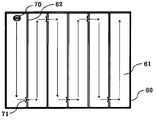
- Figure 4 shows a dye-sensitized solar cell module having a unidirectional electrolyte inlet structure and a unidirectional cell electrolyte passage in accordance with an embodiment of the present invention.
- FIG. 5 illustrates a dye-sensitized solar cell module having a unidirectional electrolyte injection hole structure and a unidirectional cell electrolyte passage according to another embodiment of the present invention.
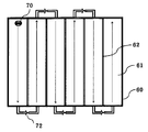
- FIG. 6 is a unidirectional electrolyte inlet structure and a unidirectional external electrode according to another embodiment of the present invention.
- the present invention provides a electrolyte injection hole structure having a one-way and a dye-sensitized solar cell module comprising the same.
- the present invention relates to a unidirectional electrolyte inlet structure for a dye-sensitized solar cell having a structure in which a fluid can be passed only while an electrolyte is injected into a cell, and a reverse flow of the electrolyte does not occur after the injection is completed.
- the fluid is allowed to flow only while the electrolyte is injected, and the structure that does not cause backflow of the electrolyte after the injection is completed, unlike the technique of preventing the electrolyte from leaking out by using an encapsulation material in the electrolyte injection hole. It is a structure that prevents the electrolyte from counting out due to the specificity of the electrolyte injection hole structure itself.
- the injection port is opened by the pressure of the injected electrolyte itself or an additional pressure applied from the outside, so that the fluid can pass therethrough, and after the injection of the electrolyte is completed, even if the pressure by the electrolyte inside the cell is applied, This means that the electrolyte can not flow back to the injection hole.
- Such a structure may be any structure as long as the structure can be opened and closed for preventing injection or backflow of the electrolyte by the structural features of the electrolyte injection hole, even if the embodiments are not described in the present invention.
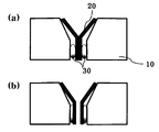
- FIG. 1 shows a unidirectional electrolyte injection hole structure according to an embodiment of the present invention.
- A) of FIG. 1 shows the structure in which the electrolyte injection opening is closed, and (b) shows the structure when the electrolyte injection opening is opened.
- the electrolyte is introduced into the structure of (a)
- the electrolyte is collected at the center of the Y-shaped electrolyte injection inducing material 20, and the elastic member 30 is formed by the pressure of the introduced electrolyte or an additional pressure applied from the outside. Will be compressed.
- the electrolyte injection inducing material 20 is opened in both directions by compression of the elastic member 30, the electrolyte may be injected into the cell or the module.
- the electrolyte injection inducing material 20 is configured such that the pressure acting inside the cell does not act in the direction in which the electrolyte inlet is opened.
- the elastic member 30 is Rather, since the pressure acts in the direction in which the electrolyte injection inducing material 20 is closed, the entire cell can be sealed by the pressure of the electrolyte itself structurally injected.
- the electrolyte injection induction material 20 has a Y-shape shape, and when the electrolyte injection hole is opened, the bent portion is bent to elasticity so that the electrolyte injection hole can be opened without additional space inside the electrolyte injection hole formed in the substrate. In addition, it may have a function that the pressure can be applied in the direction in which the open structure is closed.
- the material constituting the electrolyte injection inducing material 20 may be a rubber, a metal, an organic polymer, a ceramic material, or the like, which does not react with the electrolyte.
- the elastic member 30 may be made of one or more materials selected from the group consisting of rubber, metals, organic polymers and ceramic materials combined with these materials that do not react with the electrolyte. Since the elastic member 30 is in direct contact with the electrolyte, it should be a material that does not react with the electrolyte, and a material that does not lose elasticity even after long-term use is preferable. In addition, the elastic member 30 is not limited to the position and size illustrated in FIG. 1 as long as the position and the size of the electrolyte inlet structure allow to have a one-way structure, and a material that does not react with the electrolyte is primarily used. It is possible to construct an elastic member that is weak to the electrolyte but has better elastic properties, inside the primary elastic member or out of contact with the electrolyte.
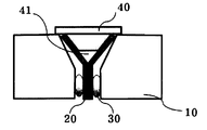
- the electrolyte injection hole structure may further include a cover portion 40 for sealing the electrolyte injection hole.
- the cover part 40 may be any structure that can seal the electrolyte injection hole, and it is possible to use a known cover part technology.
- an air layer 41 may be formed between the electrolyte injection inducing material 20 and the cover part 40. By forming the air layer 41, it is possible to more effectively prevent the electrolyte from leaking, and the pressure of the air in the air layer 41 is preferably maintained at a size at which the electrolyte injection inducing member 20 does not open.
- the cover part 40 according to the present invention is preferably composed of a member through which air cannot pass so that the air layer 41 can be maintained.
- the cover part 40 is removed, the cover part 40 is configured to be removable It is preferable that the detachable structure can use existing known techniques.
- the electrolyte injection hole structure the electrolyte injection hole is formed in the substrate, the electrolyte injection hole sealing the elastic tube capable of passing the fluid only while the electrolyte is injected, one or more air portion connected to the elastic tube and the air portion is sealed It may be characterized by including a cover portion.
- the air portion is composed of the primary air portion and the secondary air portion, and adds an elastic member capable of passing the fluid only while the electrolyte is injected between the primary air portion and the secondary air portion. It may be characterized by including as.
- FIG. 3 shows the structure of the one-way electrolyte inlet in accordance with an embodiment of the present invention.
- the elastic tube 50 is normally maintained in a closed state to allow the passage of the fluid only while the electrolyte is injected, and is composed of an elastic member to open the tube of the tube when the electrolyte is injected to generate pressure.
- the elastic tube 50 according to the present invention has a structure in which fluid is difficult to pass from the inside of the dye-sensitized solar cell to the outside, and is connected to the primary air part 42 so that the electrolyte flows back more efficiently. Can be prevented.
- the air portion functions to prevent the electrolyte from flowing out of the cell by the air pressure even when the electrolyte flows back, and preferably, the pressure of the elastic member or the elastic tube does not open.
- the primary air portion 42 is connected to the elastic member 51
- the elastic member 51 is connected to the secondary air portion 43 that the electrolyte is backflow 2 It can be configured to prevent the middle, the elastic member 51 and the elastic tube 50 are both configured to allow the fluid to pass only while the electrolyte is injected.
- the electrolyte injection hole may be sealed by the cover part 40 so that the air part may be maintained, and the cover part 40 may use a conventionally known sealing technique.
- the elastic tube 50 and the elastic member 51 may be made of at least one material selected from the group consisting of rubber, metal, organic polymer and ceramic material combined with these materials.
- the dye-sensitized solar cell module is disposed between the upper and lower transparent substrates adjacent to each other, the insulating separator is formed between the neighboring cells, the upper and lower transparent substrates One of the unidirectional electrolyte injection hole structure is formed, the insulating separator between the cells relates to a dye-sensitized solar cell module having an electrolyte passage in which the electrolyte between neighboring cells move in one direction.
- 4 and 5 illustrate a dye-sensitized solar cell module including a unidirectional electrolyte inlet structure according to another embodiment of the present invention.
- the electrolyte injected through the first one-way electrolyte inlet structure 70 pressurizes the inter-cell one-way electrolyte passage 71 configured in the cell-cell partition when the first cell is full to generate an internal pressure, thereby making it an open structure.
- the electrolyte filling the second cell through the inter-cell unidirectional electrolyte passage 71 is configured to be transferred to the third cell by internal pressure again.
- the unidirectional electrolyte inlet structure and all the unidirectional electrolyte passages between the cells are automatically converted into a structure in which the sealing is maintained.
- the electrolyte when the inside of the module is manufactured to be vacuum, the electrolyte can be more easily injected until the last cell is full due to the difference in the pressure between the cells, and the manufacturing time of the dye-sensitized solar cell can be shortened.
- the electrolyte may be filled with no empty space in which no electrolyte is introduced into the cell.
- the dye-sensitized solar cell module of the present invention may include a known electrolyte outlet in order to more fully fill the electrolyte therein, and such an outlet when manufacturing the inside of the module to be vacuum as mentioned above Without a structure would be possible.
- the dye-sensitized solar cell module including the unidirectional electrolyte inlet structure according to the present invention can directly inject the electrolyte without additional work when the electrolyte needs to be replenished. Since all the cell-cell electrolyte injection structures have a one-way structure, the electrolyte may be introduced only until the electrolyte is full, and when the inside of the module is full, leakage may be prevented by the pressure of the internal electrolyte itself.
- the electrolyte passage may be provided with an elastic member capable of elastically sealing the electrolyte injection induction material and the electrolyte injection induction material.
- the electrolyte passage may be formed in the same structure as the one-way electrolyte inlet structure according to the embodiment of the present invention, but is formed in the partition walls between cells, and thus does not require a cover part.
- the dye-sensitized solar cell module is disposed between the upper and lower transparent substrates adjacent to each other, the insulating separator is formed between the neighboring cells, the upper and lower transparent substrates
- the external electrolyte passage may be characterized by having an elastic member capable of elastically sealing the electrolyte injection induction material and the electrolyte injection induction material.
Landscapes
- Engineering & Computer Science (AREA)
- Power Engineering (AREA)
- Chemical & Material Sciences (AREA)
- Chemical Kinetics & Catalysis (AREA)
- Electrochemistry (AREA)
- Microelectronics & Electronic Packaging (AREA)
- Hybrid Cells (AREA)
- Photovoltaic Devices (AREA)
- Filling, Topping-Up Batteries (AREA)
Abstract
본 발명은 일방향성을 가지는 염료감응태양전지용 전해질 주입구 구조 및 이를 포함하는 염료감응 태양전지 모듈에 관한 것으로, 더욱 상세하게는 셀 내부로 전해질이 주입되는 동안에만 유체의 통과가 가능하고, 주입된 전해질 자체의 압력에 의해 밀봉이 유지되는 구조를 가지는 염료감응 태양전지용 일방향성 전해질 주입구 구조 및 이를 포함하는 염료감응 태양전지 모듈에 관한 것이다. 본 발명에 따른 일방향성 전해질 주입구 구조는 주입된 전해질 자체의 압력에 의하여 일방향성이 유지되기 때문에, 간단한 구조로 간편하게 전해질을 주입하고 효율적으로 전해질의 누액을 방지하는 것이 가능하며, 장기간 사용으로 전해질이 부족해지는 경우 별도의 구성없이 간편하게 전해질 보충이 가능한 효과가 있다. 또한, 염료감응 태양전지 모듈에서 셀 마다 따로 주입구를 만들지 않고 셀 간에 구성된 일방향성을 가지는 전해질 통로를 통하여 한번에 모듈을 구성하는 셀 전체에 전해질을 주입할 수 있기 때문에 염료감응태양전지 모듈의 전해질 주입구의 개수를 줄일 수 있어, 비발전 영역을 줄이고 비용의 측면에서도 유리한 효과가 있다.
Description
본 발명은 일방향성을 가지는 염료감응태양전지용 전해질 주입구 구조 및 이를 포함하는 염료감응 태양전지 모듈에 관한 것으로, 더욱 상세하게는 셀 내부로 전해질이 주입되는 동안에만 유체의 통과가 가능하고, 주입이 완료된 후에는 전해질의 역류가 발생하지 않는 구조를 가지는 염료감응 태양전지용 일방향성 전해질 주입구 구조 및 이를 포함하는 염료감응 태양전지 모듈에 관한 것이다.
환경 오염이 없는 에너지의 하나로서 태양광 에너지를 전기 에너지로 바꾸는 태양전지는 20세기 중반 실리콘계 태양전지가 등장한 이후 꾸준히 연구되어 왔다. 태양광 에너지를 얼마나 효율적으로 전기 에너지로 변환하느냐에 따라 그 효율이 결정되는데, 효율을 향상시키기 위해서는 입사하는 광을 얼마나 완벽하게 장치 내에 가두고 흡수하여 전자로 변환할 수 있는가가 중요한 요소 중 하나이다. 또한, 실리콘 태양전지는 발전 효율이 우수한 반면 그 제조 비용면에서 불리하기 때문에 그 용도가 한정되어 있으며, 태양광 발전 시스템의 원활한 보급을 위해서는 태양전지의 저비용화가 필요하다.
염료 감응형 태양전지는 투입소재의 자원적 제약이 없어 저렴하고, 차세대 태양전지로서 30% 대의 높은 이론적 변환 효율을 얻을 수 있는 광전변환 소자로 발명되었다. 이는 마이클 그라첼(Michael Gratzel) 박사에 의해서 최초로 고안되었으며, 도전성 기판 위에 이산화티타늄 등의 산화물 반도체 나노 입자를 사용한 다공막이 형성되고, 이 다공막에 염료를 담지시켜 반도체 전극이 구성되어 있다. 이 반도체 전극과 백금 스퍼터가 설치된 도전성 유리판 등의 대극이 결합되고, 양 전극사이에 요소, 요오드화물 이온 등의 산화-환원종을 포함하는 전해액이 전하 이송층으로서 역할을 할 수 있도록 채워진다. 광전극에 빛이 조사되면, 반도체 표면상에 흡착된 염료가 빛을 흡수하여 염료 분자 내의 전자가 여기되고 여기 전자가 광전극에 주입된다. 주입된 전자는 외부회로를 통하여 일(저항)을 하고 대전극으로 이동한다. 대전극에 이동한 전자는 캐리어 수송층 중의 홀 또는 이온의 형태로 운반되고 여기상태의 염료(산화상태)와 결합하여 기저상태의 염료로 환원되는 과정을 반복하므로 지속적인 발전이 이루어지게 된다.
염료 감응 태양전지는 전기화학기반 태양전지로서 반도체층이 다공질화 되고 내부 표면적이 넓기 때문에 염료를 다량 흡착할 수 있으므로, 가시광선의 파장 영역의 많은 부분의 빛을 전기로 변환할 수 있고 10%이상의 광전 변환 효율이 얻어지며, 값싼 산화 티탄을 복잡한 가공 과정 없이 사용할 수 있으므로 저 비용화가 가능하다는 이점이 있다. 또한, 상압공정으로 고가의 진공공정 및 장비가 필요하지 않으며, 비교적 낮은 온도에서 공정이 이루어지고, 유해 물질을 포함하지 않기 때문에, 대량 생산형 태양전지로서 높은 가능성을 가진다고 할 수 있다.
또한, 실리콘계 태양전지와 차별화되는 특징으로서, 완성된 제품이 투명 또는 반투명성을 가질 수 있고 잘 휘어지는 특성을 가지고 있어 실리콘계 태양전지에 비하여 떨어지는 효율을 극복하고 심미적 효과를 필요로 하는 다양한 분야에 널리 사용될 수 있을 것으로 전망되고 있다.
태양전지는 장기간 태양 광에 노출될 수 있는 외부에 배치되는 것이 일반적이기 때문에 내구성과 장기 안정성을 갖추는 것이 필수적이다. 실내 광에도 전력을 생산할 수 있는 염료감응태양전지의 경우도 장기간 안정적으로 전기를 생산할 수 있는 내구성이 필수적이지만, 액체 성분인 전해질을 포함하고 있어 전해질의 누액, 기포발생 등의 해결과제를 안고 있는 실정이다.
이러한 문제점을 해결하기 위해, 전해질을 고체 또는 준고체화 하려는 노력이 대한민국공개특허공보 제10-2009-0121218호, 제10-2009-0107861호, 일본공개특허 제2004-063758호 등에서 이루어지고 있으나, 아직 상용화 단계까지 고려할 만큼 효율의 상승 및 재료 개발이 이루어지지 못하고 있다.
또한, 액체 전해질의 누액을 방지하기 위하여 전해질 주입구를 2중으로 봉지하거나 공기압을 이용하는 구성이 일본공개특허 제2007-059181호, 일본등록특허 제4172239호 등에 개시되어 있지만 그 구성이 복잡하거나 비용이 많이 들며, 장기간 사용했을 경우 전해질 보충이 어려운 문제점이 여전히 남아 있다.
염료감응태양전지 모듈의 제조에 있어서도, 셀간 완전한 봉지를 위해서 셀 또는 단위모듈마다 전해질 주입구를 따로 마련해야 하기 때문에 비발전 영역이 늘어나고, 제조공정이 복잡하며, 비용의 측면에서도 효율적이지 못한 문제점이 남아 있다.
이에, 본 발명자들은 상기 문제점을 해결하기 위하여 예의 노력한 결과, 일방향성을 가지는 전해질 주입구 구조를 이용하여 염료감응태양전지를 제조하는 경우, 전해질 주입구의 개수를 줄일 수 있으며 전해질 주입 및 봉지가 간편하고 전해질 보충이 효율적일 뿐만 아니라, 하나의 주입구로 모듈을 구성하는 전체 셀에 전해질을 주입할 수 있어 공정이 간편하고 비용을 절감할 수 있다는 것을 확인하고, 본 발명을 완성하게 되었다.
발명의 요약
본 발명의 목적은 전해질 주입 및 봉지가 간단하고 전해질 보충이 용이한 일방향성 전해질 주입구 구조 및 이를 포함하는 염료감응태양전지 모듈을 제공하는데 있다.
상기 목적을 달성하기 위하여, 본 발명은 염료감응 태양전지에 있어서, 셀 내부로 전해질이 주입되는 동안에만 유체의 통과가 가능하고, 주입이 완료된 후에는 전해질의 역류가 발생하지 않는 구조를 가지는 염료감응 태양전지용 일방향성 전해질 주입구 구조를 제공한다.
본 발명은 또한, 상부 및 하부 투명기판 사이에 염료감응 태양전지 셀들이 서로 이웃하여 배치되고, 이웃하는 셀 사이에 절연분리막이 형성되는 염료감응 태양전지 모듈에 있어서, 상기 상부 및 하부 투명 기판 중 하나에 일방향성 전해질 주입구 구조가 형성되고, 상기 셀 사이의 절연분리막은 이웃하는 셀 사이의 전해질이 일방향성으로 이동하는 전해질 통로를 가지는 염료감응 태양전지 모듈을 제공한다.
본 발명은 또한, 상부 및 하부 투명기판 사이에 염료감응 태양전지 셀들이 서로 이웃하여 배치되고, 이웃하는 셀 사이에 절연분리막이 형성되는 염료감응 태양전지 모듈에 있어서, 상기 상부 및 하부 투명 기판 중 하나에 일방향성 전해질 주입구 구조가 형성되고, 모듈의 측면에 상기 셀과 셀을 연결하고 전해질이 이동하는 연결부재가 형성되며, 상기 연결부재에는 일방향성을 가지는 외부 전해질 통로가 형성되는 염료감응 태양전지 모듈을 제공한다.
도 1은 본 발명에 따른 일방향성 전해질 주입구 구조의 단면도를 나타낸 것이다.
도 2는 본 발명에 따른 덮개부를 추가로 포함하는 일방향성 전해질 주입구 구조의 단면도를 나타낸 것이다.
도 3은 본 발명의 다른 구현예에 따른 일방향성 전해질 주입구 구조의 단면도를 나타낸 것이다.
도 4는 본 발명의 일 구현예에 따른 일방향성 전해질 주입구 구조 및 일방향성 셀간 전해질 통로를 가지는 염료감응 태양전지 모듈을 나타낸 것이다.
도 5는 본 발명의 다른 구현예에 따른 일방향성 전해질 주입구 구조 및 일방향성 셀간 전해질 통로를 가지는 염료감응 태양전지 모듈을 나타낸 것이다.
도 6는 본 발명의 다른 구현예에 따른 일방향성 전해질 주입구 구조 및 일방향성 외부 전
발명의 상세한 설명 및 구체적인 구현예
본 발명은 일방향성을 가지는 전해질 주입구 구조 및 이를 포함하는 염료감응 태양전지 모듈을 제공한다.
본 발명은 일 관점에서, 셀 내부로 전해질이 주입되는 동안에만 유체의 통과가 가능하고, 주입이 완료된 후에는 전해질의 역류가 발생하지 않는 구조를 가지는 염료감응 태양전지용 일방향성 전해질 주입구 구조에 관한 것이다.
전해질이 주입되는 동안에만 유체의 통과가 가능하고, 주입이 완료된 후에는 전해질의 역류가 발생하지 않는 구조는, 기존의 전해질 주입홀에 봉지재료를 이용하여 전해질이 세어 나오는 것을 방지하는 기술과는 달리, 전해질 주입구 구조 자체의 특이성에 의하여 전해질이 세어 나오지 않도록 하는 구조이다. 즉, 전해질이 주입되는 동안에는 주입되는 전해질 자체의 압력 또는 외부에서 추가적으로 가한 압력에 의하여 주입구가 열려 유체의 통과가 가능한 구조가 되고, 전해질 주입이 완료된 후에는 셀 내부의 전해질에 의한 압력이 가해지더라도 전해질 주입구로 전해질이 역류할 수 없는 구조가 되는 것을 말한다. 이러한 구조는, 본 발명에서 제시하고 있는 구현예들이 아니더라도, 전해질 주입구의 구조적 특징에 의하여 전해질의 주입 또는 역류 방지를 위한 개폐가 가능한 구조라면 어떠한 구조라도 가능하다.
본 발명에 있어서, 상기 일방향성 전해질 주입구 구조는, 기판에 전해질 주입구를 형성하고, 상기 전해질 주입구에는 전해질 주입 유도 자재와 상기 전해질 주입 유도 자재를 탄력적으로 밀폐할 수 있는 탄성부재를 구비하는 것을 특징으로 할 수 있다.
도 1에서는 본 발명의 일 구현예에 의한 일방향성 전해질 주입구 구조를 나타내었다. 도 1의 (a)는 전해질 주입구가 닫혀있는 구조를 나타내고, (b)는 전해질 주입구가 열렸을 때의 구조를 나타낸 것이다. (a)의 구조에 전해질이 유입되면, Y자 모양의 전해질 주입 유도 자재(20)의 중심부에 전해질이 모이게 되고, 유입된 전해질의 압력 또는 외부에서 추가로 가한 압력에 의하여 탄성부재(30)가 압축되게 된다. 탄성부재(30)의 압축에 의하여 (b)에서 나타낸 바와 같이 전해질 주입 유도 자재(20)가 양방향으로 열리게 되면 전해질이 셀 또는 모듈의 내부로 주입될 수 있게 된다. 전해질이 셀 내부에 가득 채워지게 되어 셀 내부의 압력이 어느 정도 높아지면 구조적으로 더 이상 전해질이 주입될 수 없게 되고, 자동으로 전해질 주입구는 닫히게 된다. 전해질 주입 유도 자재(20)는 셀 내부에서 작용하는 압력이 전해질 주입구가 열리는 방향으로 작용하지 않도록 구성되어 있으며, 전해질로 가득 채워진 셀 내부의 압력이 탄성부재(30)를 가압하는 경우, 탄성부재는 오히려 전해질 주입 유도 자재(20)가 닫히는 방향으로 압력이 작용하게 되기 때문에, 구조적으로 주입된 전해질 자체의 압력에 의하여 셀 전체의 밀봉이 가능하게 된다.
본 발명에서 상기 전해질 주입 유도 자재(20)는 Y자 형태의 모양을 이루고 있으며, 전해질 주입구가 열렸을 경우 구부러진 부분이 탄력성 있도록 휘어져서 기판에 형성된 전해질 주입구 내부에서 추가적인 공간 없이 전해질 주입구가 열릴 수 있도록 하고, 추가적으로 열린 구조가 닫히는 방향으로 압력이 작용될 수 있는 기능을 가질 수 있다. 전해질 주입 유도 자재(20)를 구성하는 재료로는 전해질과 반응하지 않는 고무, 금속, 유기폴리머, 세라믹 재료 등이 가능하다.
본 발명에서 상기 탄성부재(30)는 전해질과 반응하지 않는 고무, 금속, 유기폴리머 및 이들 재료와 결합된 세라믹 재료로 이루어진 군에서 선택된 하나 이상의 재료로 이루어질 수 있다. 탄성부재(30)는 전해질과 직접적으로 닿아 있기 때문에 전해질과 반응하지 않는 물질이어야 하며, 장기간 사용에도 탄성을 잃지 않는 재료가 바람직하다. 또한, 탄성부재(30)는 전해질 주입구 구조가 일방향성을 가질 수 있도록 해주는 위치 및 크기라면 도 1에서 예시하고 있는 위치 및 크기에 한정되지 않으며, 전해질과 반응하지 않는 재료를 1차적으로 사용하고, 전해질에 약하지만 더욱 좋은 탄성 특성을 가지는 탄성부재를 1차 탄성부재 내부 또는 전해질과 닿지 않는 쪽으로 구성하는 것이 가능하다.
본 발명에 있어서, 상기 전해질 주입구 구조는 상기 전해질 주입구를 밀봉하는 덮개부(40)를 추가로 포함할 수 있다. 상기 덮개부(40)는 전해질 주입구를 밀봉할 수 있는 구조면 어느 것이든 가능하며, 공지된 덮개부 기술을 사용하는 것이 가능하다. 상기 덮개부(40)를 사용하여 전해질 주입구를 밀봉하는 경우, 전해질 주입 유도 자재(20)와 덮개부(40)의 사이에 공기층(41)을 형성할 수 있다. 상기 공기층(41)을 형성함으로써 전해질이 일부 누액되는 것을 더욱 효율적으로 방지할 수 있으며, 공기층(41)에서의 공기의 압력은 전해질 주입 유도 부재(20)가 열리지 않는 크기로 유지되는 것이 바람직하다. 본 발명에 따른 덮개부(40)는 공기층(41)이 유지될 수 있도록 공기가 통과할 수 없는 부재로 구성되는 것이 바람직하다. 또한, 본 발명에 따른 일방향성 전해질 주입 구조를 포함하는 염료감응 태양전지를 장기간 사용하여 전해질의 보충이 필요한 경우 덮개부(40)를 제거해야 하므로, 덮개부(40)는 탈착이 가능하도록 구성되는 것이 바람직하며, 탈착이 가능한 구조는 기존의 공지된 기술을 사용하는 것이 가능하다.
본 발명에 있어서, 상기 전해질 주입구 구조는, 기판에 전해질 주입구를 형성하고, 상기 전해질 주입구는 전해질이 주입되는 동안에만 유체의 통과가 가능한 탄성튜브, 탄성튜브와 연결되는 하나 이상의 공기부 및 공기부를 밀봉하는 덮개부를 포함하는 것을 특징으로 할 수 있다. 본 발명에 있어서, 상기 공기부는 제1차 공기부 및 제2차 공기부로 이루어 지고, 제1차 공기부 및 제2차 공기부의 사이에 전해질이 주입되는 동안에만 유체의 통과가 가능한 탄성부재를 추가로 포함하는 것을 특징으로 할 수 있다.
도 3는 본 발명의 일 구현예에 의한 일방향성 전해질 주입구 구조를 나타낸 것이다. 탄성튜브(50)는 전해질이 주입되는 동안에만 유체의 통과가 가능하도록 평소에는 닫혀진 상태로 유지되며, 전해질이 주입되어 압력이 발생하면 튜브의 관이 열릴 수 있도록 탄성부재로 구성된다. 본 발명에 따른 탄성튜브(50)은 염료감응 태양전지 셀 내부에서 외부로는 유체가 통과하기 어려운 구조로 형성되어 있으며, 제1차 공기부(42)와 연결되어 있어 전해질이 역류되는 것을 더욱 효율적으로 방지할 수 있다. 본 발명에 있어서 공기부는 전해질이 역류하더라도 공기압에 의하여 셀 외부로 빠져나갈 수 없도록 작용하며, 탄성부재 또는 탄성튜브가 열리지 않는 크기의 압력인 것이 바람직하다. 본 발명의 일 구현예에 의하면, 제1차 공기부(42)는 탄성부재(51)과 연결되며, 탄성부재(51)는 제2차 공기부(43)와 연결되어 전해질이 역류되는 것을 2중으로 방지할 수 있도록 구성될 수 있으며, 탄성부재(51)과 탄성튜브(50)은 모두 전해질이 주입되는 동안에만 유체가 통과할 수 있도록 구성된다. 전해질이 주입된 후에는 공기부가 유지될 수 있도록 덮개부(40)로 전해질 주입구를 밀봉할 수 있고, 상기 덮개부(40)는 기존의 공지된 밀봉 기술을 사용할 수 있다. 본 발명에서 상기 탄성튜브(50) 및 탄성부재(51)는 전해질과 반응하지 않는 고무, 금속, 유기폴리머 및 이들 재료와 결합된 세라믹 재료로 이루어진 군에서 선택된 하나 이상의 물질을 재료로 할 수 있다.
본 발명은 다른 관점에서, 상부 및 하부 투명기판 사이에 염료감응 태양전지 셀들이 서로 이웃하여 배치되고, 이웃하는 셀 사이에 절연분리막이 형성되는 염료감응 태양전지 모듈에 있어서, 상기 상부 및 하부 투명 기판 중 하나에 일방향성 전해질 주입구 구조가 형성되고, 상기 셀 사이의 절연분리막은 이웃하는 셀 사이의 전해질이 일방향성으로 이동하는 전해질 통로를 가지는 염료감응 태양전지 모듈에 관한 것이다.
도 4 및 5는 본 발명의 다른 구현예에 의한 일방향성 전해질 주입구 구조를 포함하는 염료감응태양전지 모듈을 나타낸 것이다. 도 4 및 5 에서 나타낸 바와 같이, 본 발명에 따른 일방향성 전해질 주입구 구조(70)는 모듈 전체에 하나만 구비되므로, 모듈 전체의 비발전 영역을 줄일 수 있다. 최초 일방향성 전해질 주입구 구조(70)를 통하여 주입된 전해질은 첫 번째 셀이 가득 차서 내부 압력이 생기는 경우 셀간 격벽에 구성된 셀간 일방향성 전해질 통로(71)을 가압하여 열린 구조가 되도록 한다. 셀간 일방향성 전해질 통로(71)를 통하여 두 번째 셀을 가득 채운 전해질은 또다시 내부 압력에 의하여 세 번째 셀로 넘어갈 수 있도록 구성되어 있다. 같은 방법에 의하여 마지막 셀까지 전해질이 가득 차면 일방향성 전해질 주입구 구조 및 모든 셀간 일방향성 전해질 통로는 자동으로 밀봉이 유지되는 구조로 전환되게 된다. 최초 전해질을 주입 시, 모듈의 내부를 진공이 되도록 제조하는 경우 셀간 압력의 차이에 의해 전해질이 마지막 셀이 가득 찰 때까지 더욱 용이하게 주입될 수 있으며, 염료감응태양전지 제조공정 시간을 단축시킬 수 있고, 셀 내부에 전해질이 유입되지 않은 빈공간이 없이 전해질을 가득 채울 수 있다. 필요에 따라, 본 발명의 염료감응 태양전지 모듈은 내부에 전해질을 더욱 완벽하게 가득 채우기 위해서 공지의 전해질 출구를 포함할 수 있으며, 상기 언급한 것과 같이 모듈의 내부를 진공이 되도록 제조하는 경우 이러한 출구가 없는 구조도 가능할 것이다.
본 발명에 따른 일방향성 전해질 주입구 구조를 포함하는 염료감응태양전지 모듈은 장기간 사용으로 인하여 내부에 기포가 생기는 등, 전해질의 보충이 필요한 경우 별도의 작업이 없이 바로 전해질을 주입할 수 있으며, 모듈 내의 셀간 전해질 주입 구조가 모두 일방향성을 가지므로 전해질이 가득 찰 때까지 전해질이 유입만 되고 모듈 내부가 가득 차는 경우 내부 전해질 자체의 압력에 의하여 누액이 방지되도록 구성될 수 있다.
본 발명에 있어서, 상기 전해질 통로는 전해질 주입 유도 자재와 상기 전해질 주입 유도 자재를 탄력적으로 밀폐할 수 있는 탄성부재를 구비하는 것을 특징으로 할 수 있다. 상기 전해질 통로는 본 발명의 일 구현예에 따른 일방향성 전해질 주입구 구조와 동일한 구조로 형성될 수 있으나, 셀간 격벽에 형성되므로 덮개부는 필요로 하지 않는다.
본 발명은 다른 관점에서, 상부 및 하부 투명기판 사이에 염료감응 태양전지 셀들이 서로 이웃하여 배치되고, 이웃하는 셀 사이에 절연분리막이 형성되는 염료감응 태양전지 모듈에 있어서, 상기 상부 및 하부 투명 기판 중 하나에 일방향성 전해질 주입구 구조가 형성되고, 모듈의 측면에 상기 셀과 셀을 연결하고 전해질이 이동하는 연결부재가 형성되며, 상기 연결부재에는 일방향성을 가지는 외부 전해질 통로가 형성되는 염료감응 태양전지 모듈에 관한 것이다.
도 6은 본 발명의 다른 구현예에 의한 일방향성 전해질 주입구 구조를 포함하는 염료감응 태양전지 모듈을 나타낸 것이다. 일방향성 전해질 주입구 구조(70)를 통하여 주입된 전해질은 첫번째 셀의 내부를 가득 채운 후, 연결부재(73)을 통하여 옆 셀로 이동한다. 상기 연결부재(73)에는 셀 외부 일방향성 전해질 통로(72)가 구비되어 있어, 전해질이 역류하지 못하도록 한다.
본 발명에 있어서, 상기 외부 전해질 통로는 전해질 주입 유도 자재와 상기 전해질 주입 유도 자재를 탄력적으로 밀폐할 수 있는 탄성부재를 구비하는 것을 특징으로 할 수 있다.
이상으로 본 발명 내용의 특정한 부분을 상세히 기술하였는 바, 당업계의 통상의 지식을 가진 자에게 있어서 이러한 구체적 기술은 단지 바람직한 실시태양일 뿐이며, 이에 의한 본 발명의 범위가 제한되는 것이 아닌 점은 명백할 것이다. 따라서, 본발명의 실질적인 범위는 첨부된 청구항들과 그것들의 등가물에 의하여 정의된다고 할 것이다.
부호의 설명
10 기판
20 전해질 주입 유도 자재
30 탄성부재
40 덮개부
41 공기층
42 제1차 공기부
43 제2차 공기부
50 탄성튜브
51 탄성부재
52 전해질 주입 자재
60 염료감응태양전지 모듈
61 셀
62 셀간 격벽
70 일방향성 전해질 주입구
71 셀간 일방향성 전해질 통로
72 셀 외부 일방향성 전해질 통로
73 연결부재
본 발명에 따른 일방향성 전해질 주입구 구조는 주입된 전해질 자체의 압력에 의하여 일방향성이 유지되기 때문에, 간단한 구조로 간편하게 전해질을 주입하고 효율적으로 전해질의 누액을 방지하는 것이 가능하며, 장기간 사용으로 전해질이 부족해지는 경우 별도의 구성없이 간편하게 전해질 보충이 가능한 효과가 있다.
또한, 염료감응 태양전지 모듈에서 셀 마다 따로 주입구를 만들지 않고 셀 간에 구성된 일방향성을 가지는 전해질 통로를 통하여 한번에 모듈을 구성하는 셀 전체에 전해질을 주입할 수 있기 때문에 염료감응태양전지 모듈의 전해질 주입.
Claims (17)
- 염료감응 태양전지에 있어서, 셀 내부로 전해질이 주입되는 동안에만 유체의 통과가 가능하고, 주입이 완료된 후에는 전해질의 역류가 발생하지 않는 구조를 가지는 염료감응 태양전지용 일방향성 전해질 주입구 구조.
- 제 1 항에 있어서, 상기 전해질 주입구 구조는, 기판에 전해질 주입구를 형성하고, 상기 전해질 주입구에는 전해질 주입 유도 자재와 상기 전해질 주입 유도 자재를 탄력적으로 밀폐할 수 있는 탄성부재를 구비하는 것을 특징으로 하는 염료감응 태양전지용 일방향성 전해질 주입구 구조.
- 제 2 항에 있어서, 상기 전해질 주입구 구조는 상기 전해질 주입구를 밀봉하는 덮개부를 추가로 포함하는 염료감응 태양전지용 일방향성 전해질 주입구 구조.
- 제 3 항에 있어서, 상기 덮개부는 탈착이 가능하며 전해질 주입 유도 자재와의 사이에 공기층을 형성하는 것을 특징으로 하는 염료감응 태양전지용 일방향성 전해질 주입구 구조.
- 제 1 항에 있어서, 상기 전해질 주입구 구조는, 기판에 전해질 주입구를 형성하고, 상기 전해질 주입구는 전해질이 주입되는 동안에만 유체의 통과가 가능한 탄성튜브, 탄성튜브와 연결되는 하나 이상의 공기부 및 공기부를 밀봉하는 덮개부를 포함하는 것을 특징으로 하는 염료감응 태양전지용 일방향성 전해질 주입구 구조.
- 제 5 항에 있어서, 상기 공기부는 제1차 공기부 및 제2차 공기부로 이루어 지고, 제1차 공기부 및 제2차 공기부의 사이에 전해질이 주입되는 동안에만 유체의 통과가 가능한 탄성부재를 추가로 포함하는 것을 특징으로 하는 일방향성 전해질 주입구 구조.
- 제 1 항 내지 제 6 항 중 어느 한 항의 일방향성 전해질 주입구 구조를 포함하는 염료감응 태양전지 모듈.
- 상부 및 하부 투명기판 사이에 염료감응 태양전지 셀들이 서로 이웃하여 배치되고, 이웃하는 셀 사이에 절연분리막이 형성되는 염료감응 태양전지 모듈에 있어서, 상기 상부 및 하부 투명 기판 중 하나에 일방향성 전해질 주입구 구조가 형성되고, 상기 셀 사이의 절연분리막은 이웃하는 셀 사이의 전해질이 일방향성으로 이동하는 전해질 통로를 가지는 염료감응 태양전지 모듈.
- 제 8 항에 있어서, 상기 일방향성 전해질 주입구 구조는 기판에 전해질 주입구를 형성하고, 상기 전해질 주입구에는 전해질 주입 유도 자재와 상기 전해질 주입 유도 자재를 탄력적으로 밀폐할 수 있는 탄성부재를 구비하는 것을 특징으로 하는 염료감응 태양전지 모듈.
- 제 8 항에 있어서, 상기 일방향성 전해질 주입구 구조는, 기판에 전해질 주입구를 형성하고, 상기 전해질 주입구는 전해질이 주입되는 동안에만 유체의 통과가 가능한 탄성튜브, 탄성튜브와 연결되는 하나 이상의 공기부 및 공기부를 밀봉하는 덮개부를 포함하는 것을 특징으로 하는 염료감응 태양전지 모듈.
- 제 10 항에 있어서, 상기 공기부는 제1차 공기부 및 제2차 공기부로 이루어 지고, 제1차 공기부 및 제2차 공기부의 사이에 전해질이 주입되는 동안에만 유체의 통과가 가능한 탄성부재를 추가로 포함하는 것을 특징으로 하는 염료감응 태양전지 모듈.
- 제 8 항에 있어서, 상기 전해질 통로는 전해질 주입 유도 자재와 상기 전해질 주입 유도 자재를 탄력적으로 밀폐할 수 있는 탄성부재를 구비하는 것을 특징으로 하는 염료감응 태양전지 모듈.
- 상부 및 하부 투명기판 사이에 염료감응 태양전지 셀들이 서로 이웃하여 배치되고, 이웃하는 셀 사이에 절연분리막이 형성되는 염료감응 태양전지 모듈에 있어서, 상기 상부 및 하부 투명 기판 중 하나에 일방향성 전해질 주입구 구조가 형성되고, 모듈의 측면에 상기 셀과 셀을 연결하고 전해질이 이동하는 연결부재가 형성되며, 상기 연결부재에는 일방향성을 가지는 외부 전해질 통로가 형성되는 염료감응 태양전지 모듈.
- 제 13 항에 있어서, 상기 일방향성 전해질 주입구 구조는 기판에 전해질 주입구를 형성하고, 상기 전해질 주입구에는 전해질 주입 유도 자재와 상기 전해질 주입 유도 자재를 탄력적으로 밀폐할 수 있는 탄성부재를 구비하는 것을 특징으로 하는 염료감응 태양전지 모듈.
- 제 13 항에 있어서, 상기 일방향성 전해질 주입구 구조는, 기판에 전해질 주입구를 형성하고, 상기 전해질 주입구는 전해질이 주입되는 동안에만 유체의 통과가 가능한 탄성튜브, 탄성튜브와 연결되는 하나 이상의 공기부 및 공기부를 밀봉하는 덮개부를 포함하는 것을 특징으로 하는 염료감응 태양전지 모듈.
- 제 15 항에 있어서, 상기 공기부는 제1차 공기부 및 제2차 공기부로 이루어 지고, 제1차 공기부 및 제2차 공기부의 사이에 전해질이 주입되는 동안에만 유체의 통과가 가능한 탄성부재를 추가로 포함하는 것을 특징으로 하는 염료감응 태양전지 모듈.
- 제 13 항에 있어서, 상기 외부 전해질 통로는 전해질 주입 유도 자재와 상기 전해질 주입 유도 자재를 탄력적으로 밀폐할 수 있는 탄성부재를 구비하는 것을 특징으로 하는 염료감응 태양전지 모듈.
Applications Claiming Priority (2)
| Application Number | Priority Date | Filing Date | Title |
|---|---|---|---|
| KR10-2010-0094082 | 2010-09-29 | ||
| KR1020100094082A KR20120032645A (ko) | 2010-09-29 | 2010-09-29 | 일방향성 전해질 주입구 구조 및 이를 포함하는 염료감응 태양전지 모듈 |
Publications (2)
| Publication Number | Publication Date |
|---|---|
| WO2012044005A2 true WO2012044005A2 (ko) | 2012-04-05 |
| WO2012044005A3 WO2012044005A3 (ko) | 2012-05-24 |
Family
ID=45893613
Family Applications (1)
| Application Number | Title | Priority Date | Filing Date |
|---|---|---|---|
| PCT/KR2011/006963 Ceased WO2012044005A2 (ko) | 2010-09-29 | 2011-09-21 | 일방향성 전해질 주입구 구조 및 이를 포함하는 염료감응 태양전지 모듈 |
Country Status (2)
| Country | Link |
|---|---|
| KR (1) | KR20120032645A (ko) |
| WO (1) | WO2012044005A2 (ko) |
Cited By (2)
| Publication number | Priority date | Publication date | Assignee | Title |
|---|---|---|---|---|
| US10211447B2 (en) | 2013-07-29 | 2019-02-19 | Lg Chem, Ltd. | Battery including gas discharging member and electrolyte injection member |
| CN118281097A (zh) * | 2024-04-16 | 2024-07-02 | 四川蜀旺新能源股份有限公司 | 一种太阳能热电联供用不锈钢的介质传输组件 |
Families Citing this family (1)
| Publication number | Priority date | Publication date | Assignee | Title |
|---|---|---|---|---|
| GB2551542A (en) * | 2016-06-21 | 2017-12-27 | 3Gsolar Photovoltaics Ltd | Seals for holes in solar cells |
Family Cites Families (3)
| Publication number | Priority date | Publication date | Assignee | Title |
|---|---|---|---|---|
| KR100898685B1 (ko) * | 2006-03-27 | 2009-05-22 | 삼성에스디아이 주식회사 | 이차전지 |
| KR101482657B1 (ko) * | 2008-07-16 | 2015-01-20 | 주식회사 동진쎄미켐 | 염료감응 태양전지 제작용 전해액 주입장치 및 주입방법 |
| KR20100098745A (ko) * | 2009-03-02 | 2010-09-10 | 주식회사 동진쎄미켐 | 염료감응 태양전지 |
-
2010
- 2010-09-29 KR KR1020100094082A patent/KR20120032645A/ko not_active Withdrawn
-
2011
- 2011-09-21 WO PCT/KR2011/006963 patent/WO2012044005A2/ko not_active Ceased
Cited By (2)
| Publication number | Priority date | Publication date | Assignee | Title |
|---|---|---|---|---|
| US10211447B2 (en) | 2013-07-29 | 2019-02-19 | Lg Chem, Ltd. | Battery including gas discharging member and electrolyte injection member |
| CN118281097A (zh) * | 2024-04-16 | 2024-07-02 | 四川蜀旺新能源股份有限公司 | 一种太阳能热电联供用不锈钢的介质传输组件 |
Also Published As
| Publication number | Publication date |
|---|---|
| KR20120032645A (ko) | 2012-04-06 |
| WO2012044005A3 (ko) | 2012-05-24 |
Similar Documents
| Publication | Publication Date | Title |
|---|---|---|
| Liu et al. | A solar rechargeable flow battery based on photoregeneration of two soluble redox couples | |
| Huo et al. | Nanocomposite gel electrolyte with large enhanced charge transport properties of an I3−/I− redox couple for quasi-solid-state dye-sensitized solar cells | |
| CN101842934B (zh) | 染料敏化太阳能电池模块 | |
| Zhang et al. | Highly flexible and scalable photo-rechargeable power unit based on symmetrical nanotube arrays | |
| Kim et al. | A highly efficient self-power pack system integrating supercapacitors and photovoltaics with an area-saving monolithic architecture | |
| JPS58216476A (ja) | 光発電蓄電装置 | |
| CN108448146B (zh) | 一种单板框的氧化还原液流电池电堆结构 | |
| US20090020159A1 (en) | Dye-sensitized solar cell | |
| CN103996733A (zh) | 一种光电核电池 | |
| WO2012044005A2 (ko) | 일방향성 전해질 주입구 구조 및 이를 포함하는 염료감응 태양전지 모듈 | |
| CN107275095B (zh) | 一种可用染料敏化太阳能充电的复合型锂离子二次电池 | |
| KR101482649B1 (ko) | 염료감응 태양전지 및 모듈 | |
| EP4174960A1 (en) | Photovoltaic module | |
| CN202454666U (zh) | 集流板及包括其的液流电池堆 | |
| CN100483829C (zh) | 堆叠式硅基微型燃料电池组及其制作方法 | |
| CN102254686B (zh) | 一种用于染料敏化太阳能电池的电解质片及其制备方法 | |
| US20130081672A1 (en) | Nano power cell and method of use | |
| WO2010137781A1 (ko) | 염료감응 태양전지의 제조 방법 | |
| CN104119501A (zh) | 含噻吩并噻吩-二噻吩并苯并噻二唑-苯并噻二唑类共轭聚合物及其制备方法与应用 | |
| Zhang et al. | Dual-Functional Cs3Bi2Br9 for stable all-solid-state photo-rechargeable batteries | |
| CN109616326B (zh) | 一种一步电沉积制备导电玻璃基底/离子液体掺杂的n型聚苯胺薄膜的方法和应用 | |
| KR101005052B1 (ko) | 염료감응 태양전지 모듈 | |
| CN102468055A (zh) | 一种分层吸附染料敏化太阳能电池及其制备方法 | |
| WO2012081759A1 (ko) | 채널 구조의 유기박막 태양전지 제조방법 | |
| CN102254700A (zh) | 层叠结构的光侧入式染料敏化太阳能电池组及其制造工艺 |
Legal Events
| Date | Code | Title | Description |
|---|---|---|---|
| 121 | Ep: the epo has been informed by wipo that ep was designated in this application |
Ref document number: 11829511 Country of ref document: EP Kind code of ref document: A2 |
|
| NENP | Non-entry into the national phase |
Ref country code: DE |
|
| 32PN | Ep: public notification in the ep bulletin as address of the adressee cannot be established |
Free format text: NOTING OF LOSS OF RIGHTS PURSUANT TO RULE 112(1) EPC (EPO FORM 1205 DATED 06.06.2013) |
|
| 122 | Ep: pct application non-entry in european phase |
Ref document number: 11829511 Country of ref document: EP Kind code of ref document: A2 |