WO2012036028A1 - Navigation signal transmission device, location information providing device, method for transmitting navigation signal, and method for providing location information - Google Patents
Navigation signal transmission device, location information providing device, method for transmitting navigation signal, and method for providing location information Download PDFInfo
- Publication number
- WO2012036028A1 WO2012036028A1 PCT/JP2011/070277 JP2011070277W WO2012036028A1 WO 2012036028 A1 WO2012036028 A1 WO 2012036028A1 JP 2011070277 W JP2011070277 W JP 2011070277W WO 2012036028 A1 WO2012036028 A1 WO 2012036028A1
- Authority
- WO
- WIPO (PCT)
- Prior art keywords
- signal
- positioning
- information
- navigation
- data
- Prior art date
Links
Images


Classifications
-
- H—ELECTRICITY
- H04—ELECTRIC COMMUNICATION TECHNIQUE
- H04W—WIRELESS COMMUNICATION NETWORKS
- H04W4/00—Services specially adapted for wireless communication networks; Facilities therefor
- H04W4/02—Services making use of location information
-
- H—ELECTRICITY
- H04—ELECTRIC COMMUNICATION TECHNIQUE
- H04B—TRANSMISSION
- H04B1/00—Details of transmission systems, not covered by a single one of groups H04B3/00 - H04B13/00; Details of transmission systems not characterised by the medium used for transmission
- H04B1/69—Spread spectrum techniques
-
- G—PHYSICS
- G01—MEASURING; TESTING
- G01C—MEASURING DISTANCES, LEVELS OR BEARINGS; SURVEYING; NAVIGATION; GYROSCOPIC INSTRUMENTS; PHOTOGRAMMETRY OR VIDEOGRAMMETRY
- G01C21/00—Navigation; Navigational instruments not provided for in groups G01C1/00 - G01C19/00
- G01C21/20—Instruments for performing navigational calculations
- G01C21/206—Instruments for performing navigational calculations specially adapted for indoor navigation
-
- G—PHYSICS
- G01—MEASURING; TESTING
- G01S—RADIO DIRECTION-FINDING; RADIO NAVIGATION; DETERMINING DISTANCE OR VELOCITY BY USE OF RADIO WAVES; LOCATING OR PRESENCE-DETECTING BY USE OF THE REFLECTION OR RERADIATION OF RADIO WAVES; ANALOGOUS ARRANGEMENTS USING OTHER WAVES
- G01S19/00—Satellite radio beacon positioning systems; Determining position, velocity or attitude using signals transmitted by such systems
- G01S19/01—Satellite radio beacon positioning systems transmitting time-stamped messages, e.g. GPS [Global Positioning System], GLONASS [Global Orbiting Navigation Satellite System] or GALILEO
- G01S19/03—Cooperating elements; Interaction or communication between different cooperating elements or between cooperating elements and receivers
- G01S19/10—Cooperating elements; Interaction or communication between different cooperating elements or between cooperating elements and receivers providing dedicated supplementary positioning signals
- G01S19/11—Cooperating elements; Interaction or communication between different cooperating elements or between cooperating elements and receivers providing dedicated supplementary positioning signals wherein the cooperating elements are pseudolites or satellite radio beacon positioning system signal repeaters
-
- G—PHYSICS
- G01—MEASURING; TESTING
- G01S—RADIO DIRECTION-FINDING; RADIO NAVIGATION; DETERMINING DISTANCE OR VELOCITY BY USE OF RADIO WAVES; LOCATING OR PRESENCE-DETECTING BY USE OF THE REFLECTION OR RERADIATION OF RADIO WAVES; ANALOGOUS ARRANGEMENTS USING OTHER WAVES
- G01S19/00—Satellite radio beacon positioning systems; Determining position, velocity or attitude using signals transmitted by such systems
- G01S19/38—Determining a navigation solution using signals transmitted by a satellite radio beacon positioning system
- G01S19/39—Determining a navigation solution using signals transmitted by a satellite radio beacon positioning system the satellite radio beacon positioning system transmitting time-stamped messages, e.g. GPS [Global Positioning System], GLONASS [Global Orbiting Navigation Satellite System] or GALILEO
- G01S19/42—Determining position
- G01S19/48—Determining position by combining or switching between position solutions derived from the satellite radio beacon positioning system and position solutions derived from a further system
-
- H—ELECTRICITY
- H04—ELECTRIC COMMUNICATION TECHNIQUE
- H04W—WIRELESS COMMUNICATION NETWORKS
- H04W4/00—Services specially adapted for wireless communication networks; Facilities therefor
- H04W4/02—Services making use of location information
- H04W4/024—Guidance services
Definitions
- the present invention relates to a technique for providing position information, and relates to a navigation signal transmitting apparatus and a position information providing apparatus for transmitting a navigation signal. More specifically, the present invention relates to a technique for providing position information even in an environment where a signal transmitted from a satellite that transmits a positioning signal does not reach.
- GPS Global Positioning System
- GPS satellite A satellite for transmitting a signal used for GPS (hereinafter referred to as “GPS signal”) (hereinafter referred to as a GPS satellite) is flying at an altitude of about 20,000 km from the ground.
- GPS signal a signal used for GPS
- the user can measure the distance between the GPS satellite and the user by receiving and demodulating the signal transmitted from the GPS satellite. Therefore, when there is no obstacle between the ground and the GPS satellite, positioning using a signal transmitted from the GPS satellite is possible.
- GPS satellite for example, when using GPS in an urban area, a building that stands in the forest becomes an obstacle, and the user's location information providing device often cannot receive signals transmitted from GPS satellites. Further, due to the diffraction or reflection of the signal by the building, an error occurs in the distance measurement using the signal, and as a result, the positioning accuracy often deteriorates.
- the positioning has been described by taking the GPS as an example, but the phenomenon described above is generally applicable to a positioning system using a satellite.
- the satellite positioning system is not limited to GPS, and includes, for example, systems such as GLONASS (GLObal NAvigation Satellite System) in the Russian Republic and Galileo in Europe.
- GLONASS GLObal NAvigation Satellite System
- Patent Document 1 Japanese Patent Application Laid-Open No. 2006-67086
- the reader or writer is unique to a system that provides position information, and there is a problem that it is versatile. In order to avoid interference, it is necessary to suppress transmission output, the range in which position information can be received is limited, continuous position information cannot be acquired, and a large number of transmitters are required to cover a wide range. There was a problem that it was necessary.
- the location information is acquired at a location where a signal from a satellite can be received, and thus the location of the mobile phone can be notified.
- position information cannot be obtained by a conventional positioning technique in a place where radio waves cannot be received such as indoors and underground shopping streets.
- a technique is also conceivable in which a plurality of transmitters capable of transmitting a signal similar to a GPS signal are arranged in a room and the position is obtained based on the principle of three-side surveying similar to GPS (for example, JP 2000-180527 A). No. (Patent Document 2)).
- Patent Document 2 Patent Document 2
- the time of each transmitter needs to be synchronized and the transmitter becomes expensive.
- the arrangement of the radio wave shield / reflector is a constant arrangement in the moving direction of the receiving terminal for positioning, and multipath It is a technology that tries to reduce the influence of the above.
- Patent Document 3 discloses that transmission power is controlled indoors, and indoors, instead of the above three-sided surveying, position information is simply compatible with GPS signals. A technique for improving the accuracy of positioning while simplifying the system configuration in indoor positioning by transmitting in a simple format is disclosed.
- SVG Scalable Vector Graphics
- SVG technology is known as a technology that can display a map in a scalable manner.
- a map using the SVG technology for example, a map of a Japanese urban area is also disclosed by the Geographical Survey Institute.
- the SVG technology has the following characteristics.
- SVG is an “open standard” format that is being internationally standardized by global standards organizations such as W3C and OMA.
- SVG is “XML data with semantic information”, and display content can be dynamically controlled on the client side in accordance with the context on the user side when combining content.
- SVG is a vector format image format, which enables high-quality enlargement / reduction / rotation of map images.
- Japanese Patent No. 3503397 discloses a technique for displaying a map in cooperation with a plurality of geographic information servers using map information that is scalable map information such as SVG and can be referred to each other.
- Patent Document 4 discloses a technique for displaying a map in cooperation with a plurality of geographic information servers using map information that is scalable map information such as SVG and can be referred to each other.
- the present invention has been made to solve the above-described problems, and an object of the present invention is to provide a navigation signal transmitting apparatus capable of realizing a reduction in positioning time by a positioning signal from an indoor positioning transmitter. And providing a position information providing apparatus.
- Another object of the present invention is to provide a navigation signal transmitting apparatus and a position information providing apparatus capable of improving positioning accuracy and shortening positioning time when performing a positioning handover from indoor to outdoor. That is.
- Another object of the present invention is to provide a method for transmitting a navigation signal and a method for providing position information capable of realizing a reduction in positioning time by a positioning signal from an indoor positioning transmitter. That is.
- Still another object of the present invention is to provide a method for transmitting a navigation signal capable of improving positioning accuracy and shortening positioning time when performing positioning handover from indoor to outdoor, and It is to provide a method for providing location information.
- navigation installed in a ground facility that receives a spread spectrum satellite positioning signal from a plurality of positioning satellites and transmits the navigation signal to a receiver capable of positioning.
- a signal transmission device is provided.
- the navigation signal transmission device includes a transmission antenna, identification information for identifying the navigation signal transmission device among a plurality of navigation signal transmission devices installed in the facility, and an external for acquiring map information in the facility.
- a storage device for storing resource identification information for specifying the position of the device on the network, a message generator for generating identification information included in the navigation signal and a message signal of the resource identification information, and navigation signal transmission
- a modulator that generates a navigation signal by modulating a message signal by a modulation process including a spread spectrum process based on a spread code of the same series as that of a satellite positioning signal assigned in advance to the device; From the transmitter.
- the signal format of the navigation signal is compatible with the signal format of the satellite positioning signal.
- the message generator generates a message signal including identification information in a signal format having the shortest signal repetition period among a plurality of signal formats compatible with the signal format of the satellite positioning signal.
- a positioning by receiving a satellite positioning signal having a spread spectrum from a plurality of positioning satellites, and to transmit a plurality of navigation signals installed in a ground facility.
- a position information providing apparatus that provides position information using a plurality of navigation signals that are spread spectrum signals from the apparatus and each include identification information for identifying the navigation signal transmitting apparatus in the facility.
- This position information providing apparatus stores a receiver for receiving a spread spectrum signal, a communication circuit for communicating with an external device on the network, and a plurality of spreading code patterns of the same series as the satellite positioning signal for the navigation signal.
- the resource identification information for specifying the position of the external device on the network is acquired from the navigation signal from the predetermined navigation signal transmission device, and the identification information is obtained by any one of the plurality of identified navigation signals.
- an external device based on the resource identification information by an extractor for extracting From which the map information for displaying the map in the facility and the correspondence information indicating the correspondence relationship between the position of the navigation signal transmitting device in the facility and the identification information are acquired and the identification information is received in the map in the facility
- a map drawing processor for generating an image signal for displaying a map image indicating the position of the signal transmission device.
- the signal format of the navigation signal is compatible with the signal format of the satellite positioning signal.
- the map information is SVG (Scalable Vector Graphics) format data, and the correspondence information is described as SVG format data.
- the correspondence information collectively includes the correspondence between the positions of the plurality of navigation signal transmitting devices included in the map information and the plurality of identification information.
- the demodulator performs a correlation process using the selected spreading code based on the correspondence information.
- the extractor acquires satellite orbit data about the positioning satellite from the external device when acquiring the map information from the external device.
- the position information providing device further includes an outdoor positioning circuit that performs positioning using satellite orbit data acquired from an external device when positioning is performed by receiving satellite positioning signals from a plurality of positioning satellites.
- a method for transmitting navigation signals from a facility on the ground to a receiver capable of receiving and performing spread spectrum satellite positioning signals from a plurality of positioning satellites Provided.
- identification information for identifying the navigation signal transmission device and a position on the network of an external device for acquiring the map information in the facility Preparing the resource identification information for identifying the identification information, generating the identification information included in the navigation signal and the message signal of the resource identification information, and the same satellite positioning signal preassigned to the navigation signal transmitting device
- the message signal is modulated by a modulation process including a spread spectrum process to generate a navigation signal, and the navigation signal is transmitted from the transmission antenna.
- the signal format of the navigation signal is compatible with the signal format of the satellite positioning signal.
- the step of generating the message signal includes the step of generating a message signal including identification information in a signal format having the shortest signal repetition period among a plurality of signal formats compatible with the signal format of the satellite positioning signal. Including.
- a plurality of navigation signals can be measured by receiving a spectrum-spread satellite positioning signal from a plurality of positioning satellites and installed in a ground facility.
- a method for providing position information using a plurality of navigation signals each of which is a spread spectrum signal from a transmission device and includes identification information for identifying the navigation signal transmission device in the facility.
- the method includes receiving a spread spectrum signal, communicating with an external device on the network, storing a plurality of spreading code patterns in the same series as the satellite positioning signal for the navigation signal, and a plurality of spreading A step of performing a correlation process on the code pattern in parallel to identify and demodulate a plurality of navigation signals, and when the navigation signals can be identified and demodulated, a navigation signal from a predetermined navigation signal transmitting device
- Obtaining resource identification information for specifying a position on the network extracting the identification information from any one of the identified plurality of navigation signals, and from an external device based on the resource identification information , Map information and facility to display the map in the facility
- Map information and facility to display the map in the facility
- the image for displaying the map information which shows the position of the navigation signal transmitter which acquired the correspondence information which shows the correspondence of the position of the navigation signal transmitter in the inside, and identification information, and received the identification information in the map in a facility Generating a signal.
- the signal format of the navigation signal is compatible with the signal format of the satellite positioning signal.
- the map information is SVG (Scalable Vector Graphics) format data, and the correspondence information is described as SVG format data.
- the correspondence information collectively includes the correspondence between the positions of the plurality of navigation signal transmitting devices included in the map information and the plurality of identification information.
- the step of demodulating includes the step of performing correlation processing using the selected spreading code based on the correspondence information.
- the step of extracting includes the step of acquiring the satellite orbit data for the positioning satellite from the external device when the map information is acquired from the external device.
- the method further includes the step of performing positioning using satellite orbit data acquired from an external device when positioning is performed by receiving satellite positioning signals from a plurality of positioning satellites.
- the positioning time can be shortened by the positioning signal from the indoor positioning transmitter on the receiver side.
- the positioning accuracy is improved and the positioning is performed at the receiver side when the positioning handover is performed from indoor to outdoor. Time can be shortened.
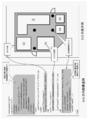
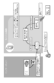
- FIG. 1 is a diagram illustrating a configuration of a position information providing system 10.
- FIG. 2 is a block diagram showing a hardware configuration of an indoor transmitter 200.
- FIG. It is a figure which represents notionally the one aspect
- a baseband signal of a C / A (Coarse and Acquisition) code which is a positioning signal carried on the L1 band (1575.42 MHz) of the current GPS signal carrier, or a new positioning satellite
- a modulator 245a for modulating a baseband signal of an L1C code which is a positioning signal used in the L1 band of a system (for example, a Japanese quasi-zenith satellite system), in accordance with each signal format.
- chord may be transmitted. It is a figure showing the structure of the signal 500 transmitted by the transmitter mounted in a GPS satellite. It is a figure showing the 1st structure of a L1C compatible signal. It is a figure showing the 2nd structure of a L1C compatible signal.
- FIG. 20 It is a figure which compares and shows the data (SVG container) of SVG map information, and the map image displayed with the data of the said SVG map information.
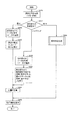
- 5 is a flowchart showing a procedure of processes executed by baseband processor 410 and navigation processor 430 of position information providing apparatus 100.
- S630 the indoor positioning process
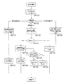
- FIG. 20 it is a figure which shows notionally the process in the case of showing a positional information based on transmitter ID (SID) and the SVG map information data from a server.
- SID transmitter ID
- FIG. 20 Concept of indoor positioning processing based on the identifier of the indoor transmitter from the indoor transmitter and SVG map information data from the server, and outdoor positioning processing using orbit information received together with the SVG map information data
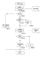
- FIG. It is a 1st flowchart for demonstrating the process of the indoor positioning process (step S630 of FIG. 20) in the positional information provision apparatus 100 of Embodiment 2.
- FIG. It is a flowchart for demonstrating the positioning process in FIG. It is a flowchart for demonstrating the flow of a process of the operation
- FIG. 1 is a diagram illustrating a configuration of a position information providing system 10.
- the position information providing system 10 flies at an altitude of about 20,000 km above the ground and transmits GPS satellites 110, 111, 112, 113 that transmit signals for positioning (hereinafter referred to as “positioning signals”), Position information providing devices 100-1 to 100-4 functioning as devices that provide position information.
- the location information providing devices 100-1 to 100-4 are collectively referred to as the location information providing device 100.
- the position information providing device 100 has a hardware configuration similar to that of a terminal having a conventional positioning device, such as a mobile phone, a car navigation system, and other mobile positioning devices.
- a conventional positioning device such as a mobile phone, a car navigation system, and other mobile positioning devices.
- the position information providing apparatus 100 according to the embodiment of the present invention is realized as a terminal apparatus capable of positioning even indoors.
- the positioning signal is a so-called spread spectrum signal, for example, a so-called GPS signal.
- the signal is not limited to a GPS signal.
- the positioning system will be described using GPS as an example.
- the present invention is not limited to other satellite positioning systems (for example, Galileo, Quasi-Zenith Satellite System (QZSS)). Etc.).
- the center frequency of the positioning signal is 1575.42 MHz, for example.
- the spread frequency of the positioning signal is, for example, 1.023 MHz.
- the frequency of the positioning signal is the same as the frequency of the C / A (Coarse and Acquisition) signal or L1C signal in the existing GPS L1 band. Therefore, since the front end of an existing positioning signal receiving circuit (for example, a GPS signal receiving circuit) can be used, the position information providing apparatus 100 performs signal processing from the front end without adding a new hardware circuit. A positioning signal can be received simply by changing the software.
- the positioning signal may be modulated by a 1.023 MHz rectangular wave.
- the user receives the positioning signal using a receiver that can receive and process a new GPS signal. it can.
- the frequency of the rectangular wave is preferably 1.023 MHz.
- the frequency for modulation may be determined by a trade-off with existing C / A signals and / or spectrum separation to avoid interference with other signals. The mode of modulation is not limited to this.
- the GPS satellite 110 is equipped with a transmitter 120 that transmits a positioning signal. Similar transmitters 121, 122, and 123 are mounted on the GPS satellites 111, 112, and 113, respectively.
- the location information providing devices 100-2, 100-3, 100-4 having the same functions as the location information providing device 100-1 can be used in buildings 130 and other places where radio waves are difficult to reach, as will be described below. is there. That is, the indoor transmitter 200-1 is attached to the ceiling of the first floor of the building 130. Position information providing apparatus 100-4 receives a positioning signal transmitted from indoor transmitter 200-1. Similarly, indoor transmitters 200-2 and 200-3 are also attached to the ceilings of the second and third floors of the building 130, respectively.
- the time of each indoor transmitter 200-1, 200-2, 200-3 hereinafter referred to as “ground time”
- the time of the GPS satellites 110, 111, 112, 113 hereinafter referred to as “satellite time”.
- each satellite time May be independent of each other and need not be synchronized.
- each satellite time needs to be synchronized. Therefore, each satellite time is controlled by an atomic clock mounted on each satellite.
- the ground time which is the time of each indoor transmitter 200-1, 200-2, 200-3, is also synchronized with each other as necessary.
- the time of the indoor transmitters 200-1, 200-2, 200-3 and the satellite time can be synchronized with a relatively simple device configuration.
- it is necessary to synchronize the time with the ground time it is possible to cope with such synchronization.
- a spread spectrum signal transmitted as a positioning signal from each transmitter of a GPS satellite is generated by modulating a navigation message with a pseudo noise code (PRN (Pseudo Random Noise) code).
- the navigation message includes time data, orbit information, almanac, ionospheric correction data, and the like.
- Each transmitter 120 to 123 further receives data (for example, PRN-ID (Identification)) for identifying the transmitter 120 to 123 itself or each GPS satellite in which the transmitter 120 to 123 is mounted. keeping.
- the position information providing apparatus 100 has data and a code generator for generating each pseudo-noise code.
- the position information providing apparatus 100 executes a demodulation process, which will be described later, using a code pattern of a pseudo-noise code assigned to each satellite transmitter or each indoor transmitter, and receives the received signal. Can be identified from which satellite or from which indoor transmitter.
- the L1C signal which is one of the positioning signals, includes a PRN-ID in the data, thereby preventing signal acquisition / tracking with an erroneous code pattern that is likely to occur when the reception level is low. it can.
- the transmitters 120, 121, 122, and 123 each perform an atomic clock, a storage device that stores data, an oscillation circuit, a processing circuit that generates a positioning signal, and a spectrum generated by a signal generated by the processing circuit.
- An encoding circuit for encoding, a transmission antenna, and the like are included.
- the storage device stores ephemeris, almanac of each satellite, navigation message having ionospheric correction data, and the like.
- the processing circuit When each transmitter transmits an L1C / A signal, the processing circuit generates a positioning signal with a code pattern that can be a PRN-ID. Therefore, if the code pattern of the received positioning signal is specified, the transmitter that transmitted the positioning signal is identified.
- the storage device stores the PRN-ID.
- the processing circuit generates a positioning signal including the PRN-ID. Therefore, when the positioning signal generated as the L1C signal is received, the PRN-ID is acquired from the positioning signal.
- the processing circuit generates a message for transmission using the time information from the atomic clock and each data stored in the storage device.
- each of the transmitters 120 to 123 a code pattern of a pseudo noise code for performing spread spectrum encoding is defined in advance. Each code pattern is different for each transmitter (that is, for each GPS satellite). The encoding circuit spreads the message using such a pseudo-noise code. Each of the transmitters 120 to 123 converts the encoded signal into a high frequency and transmits it to outer space via a transmission antenna.
- the transmitters 120 to 123 transmit spread spectrum signals that do not cause harmful interference with other transmitters.
- “not causing harmful interference” can be ensured by an output level limited to such an extent that interference does not occur.
- This signal is transmitted by a carrier wave called L1 band, for example.
- Each transmitter 120, 121, 122, 123 transmits a positioning signal having the same frequency, for example, according to a spread spectrum communication system. Therefore, even when positioning signals transmitted from the respective satellites are received by the same position information providing apparatus 100-1, the positioning signals are received without mutual interference.
- the positioning signal from the indoor transmitter on the ground similarly to the signal transmitted from the satellite, signals from a plurality of indoor transmitters can be received without mutual interference.
- FIG. 2 is a block diagram illustrating a hardware configuration of the indoor transmitter 200.
- the indoor transmitter 200 is a general term for the indoor transmitters 200-1, 200-2, and 200-3.
- the indoor transmitter 200 is electrically connected to a wireless interface (hereinafter referred to as “wireless I / F”) 210, a digital processing block 240, and the digital processing block 240 to operate each circuit portion.
- An antenna (not shown) that is electrically connected to 250 and transmits a signal for positioning, and a power source (not shown) for supplying a power supply potential to each part of the indoor transmitter 200 are provided. .
- the power source may be built in the indoor transmitter 200 or may be configured to accept external power supply.
- the wireless I / F 210 is an interface for wireless communication, and short-distance wireless communication such as Bluetooth (Bluetooth), PHS (Personal Handy-phone System), or wireless communication such as a mobile phone network, commands from the outside. For receiving setting parameters and program (firmware, etc.) data from the outside, or transmitting data to the outside as necessary.
- short-distance wireless communication such as Bluetooth (Bluetooth), PHS (Personal Handy-phone System), or wireless communication such as a mobile phone network
- Bluetooth Bluetooth
- PHS Personal Handy-phone System
- wireless communication such as a mobile phone network
- the indoor transmitter 200 can be set parameters such as position data (indoor transmitter transmitted by the indoor transmitter 200) even after installation on an indoor ceiling or the like.
- the data representing the place where the computer 200 is installed can be changed, or by changing the firmware, it is possible to cope with different communication methods.
- access to the indoor transmitter 200 via the wireless I / F 210 is preferably protected by an ID and a password. In this way, modification of data or programs by a third party other than the administrator of the indoor transmitter 200 can be prevented.
- a wireless interface is assumed. However, if a wired interface can be used even when wiring is installed at the installation site or installation is taken into consideration, the wired interface is used. It is also possible.
- the communication is realized by public line, LAN (Local Area Network), USB (Universal Serial Bus) serial distribution, etc., but is not particularly limited.
- LAN Local Area Network
- USB Universal Serial Bus
- the digital processing block 240 is mounted on the processor 241 that controls the operation of the indoor transmitter 200 according to a command from the wireless I / F 210 or according to a program, and stores a program executed by the processor 241.
- a RAM Random Access Memory
- EEPROM Electrically Erasable and Programmable Read Only Memory
- the digital processing block 240 generates data serving as a source of a signal transmitted by the indoor transmitter 200 as a positioning signal.
- the digital processing block 240 sends the generated data as a bit stream to the analog processing block 250.
- the firmware program stored in the EEPROM 244 is loaded into the FPGA 245 when the FPGA 245 is powered on.
- This firmware program information (bit stream data) is loaded into a configuration memory configured by SRAM (Static Random Access Memory) 246 in FPGA 245.
- SRAM Static Random Access Memory
- Each bit data of the loaded bit stream data becomes an information source of a circuit realized on the FPGA 245, and a circuit specified by the firmware program is realized by customizing resources provided in the FPGA 245.
- the FPGA 245 can achieve high versatility and flexibility by having configuration data outside without depending on the hardware.
- the processor 241 sets the following parameters as parameters set in the indoor transmitter 200 in the SRAM 246 (register) of the FPGA 245 based on data stored in the EEPROM 243 in accordance with an external command received from the wireless I / F 210. Store things.
- the information for specifying the position where the SVG map information exists on the web server may be more generally a URI (Uniform Resource Identifier).
- the URI is also simply referred to as “resource identification information”.
- the resource identification information will be described below as URL information.
- bandpass filters for 1 MHz, 2 MHz, and 4 MHz are pre-programmed, and the “digital filter selection parameter” This is a parameter for selecting which band pass filter.
- a program for the operation of the processor 241 is also stored in the EEPROM 243 in advance, and the program is read from the EEPROM 243 and transferred to the RAM 242 when the indoor transmitter 200 is activated.
- the storage device for storing the program or data is not limited to the EEPROM 243 or 244. Any storage device that can store data in a nonvolatile manner may be used. Further, as will be described later, when external data is input, any storage device capable of writing data may be used. The data structure of data stored in the EEPROM 243 will be described later.
- the analog processing block 250 uses the bit stream output from the digital processing block 240 to modulate a 1.57542 GHz carrier wave, generates a transmission signal, and transmits the transmission signal to the antenna. The signal is transmitted from the antenna.
- the signal output from the D / A converter 247 of the digital processing block 240 is up-converted by the up-converter 252 and passes through the band-pass filter (BPF) 253 through the amplifier 254 to amplify only a signal in a predetermined frequency band.
- BPF band-pass filter
- the signal is up-converted again by the up-converter 255 and a signal of a predetermined band is extracted by a SAW (Surface Acoustic Wave) filter, and then the signal is set to a signal having a set strength by the variable attenuator 257 and the RF switch 258 It is converted and sent out from the antenna.
- SAW Surface Acoustic Wave
- the mode of signal generation is not limited to the above.
- the above example shows an example in which two-stage modulation is performed, but one-stage modulation may be used, or signal conversion may be performed directly.
- the clock used by the up-converter 252 and the up-converter 255 is obtained by multiplying the clock supplied from the reference clock I / O block 230 to the FPGA 245 by the multiplier 251.
- variable attenuator 257 and the RF switch 258 The level setting of the variable attenuator 257 and the RF switch 258 is controlled by a control signal from the processor 241 that has passed through the FPGA 245. The signal intensity is changed by the variable attenuator 257. Both the variable attenuator 257 and the RF switch 258 operate as part of an “individual variable function of IQ modulation amplitude” described later.
- a signal having the same configuration (same signal format) as a signal for positioning from a satellite is transmitted from the indoor transmitter 200.
- the content of the signal is not exactly the same as the content included in the positioning signal transmitted from the satellite, it can be said that both signals are compatible with each other when viewed from the receiver side.
- An example of the configuration of a signal transmitted from the indoor transmitter 200 will be described later (FIG. 8).
- the FPGA 245 is used as the arithmetic processing device for realizing the digital signal processing in the digital processing block 240.
- other arithmetic processing can be used as long as the device can change the modulation function of the wireless device by software.
- a device may be used.
- the clock signal (Clk) is supplied from the digital processing block 240 to the analog processing block 250, but may be supplied directly from the reference clock I / O block 230 to the analog processing block 250.
- digital processing block 240 and the analog processing block 250 are separately shown in the present embodiment, but physically, they may be mixedly mounted on one chip. .
- the reference clock I / O block 230 supplies the digital processing block 240 with a clock signal that defines the operation of the digital processing block 240 or a clock signal for generating a carrier wave.
- the reference clock I / O block 230 supplies the clock signal to the digital processing block 240 and the like based on the synchronization signal supplied from the external clock generator to the external synchronization link port 220. To do.
- the operation in the “external synchronization mode” will be described in more detail later.
- the reference clock I / O block 230 selects an external clock signal supplied to the external clock port 221 by the multiplexer 232, and outputs a clock signal output from a PLL (Phase Locked Loop) circuit 233. In synchronization with the external clock, the synchronized clock signal is supplied to the digital processing block 240 and the like.
- PLL Phase Locked Loop
- the reference clock I / O block 230 selects the internal clock signal generated by the internal clock generator 231 using the multiplexer 232, and outputs the clock signal output from the PLL circuit 233 and the internal clock. Synchronously, the synchronized clock signal is supplied to the digital processing block 240 and the like.
- the internal state of the transmitter (for example, a “PLL control” signal) can be monitored by a signal output from the wireless I / F 210 by the processor 241.
- the wireless I / F 210 inputs a code pattern of a pseudo-noise code for spreading and modulating a signal transmitted from the indoor transmitter 200, or the wireless I / F 210 should be transmitted from the indoor transmitter 200
- Input of other data can also be accepted.
- the other data is, for example, text data (position data) representing a place where the indoor transmitter 200 is installed.
- advertisement data can be input to the indoor transmitter 200 as the other data.
- PRN code pseudo noise code
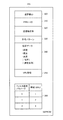
- FIG. 3 is a diagram conceptually showing one mode of data storage in EEPROM 243 provided in indoor transmitter 200.
- the EEPROM 243 includes areas 300 to 350 for storing data.
- a transmitter ID is stored as a number for identifying the transmitter.
- the transmitter ID is, for example, a number and / or English character or other combination that is written in a memory in a nonvolatile manner when the transmitter is manufactured or installed.
- the transmitter ID is associated as a unique ID with a location where the transmitter is installed (such as geographical location information, an address, or other artificially determined location information). .
- the PRN-ID of the pseudo noise code assigned to the transmitter is stored in the area 310.
- the name of the transmitter is stored in area 320 as text data.
- the code pattern of the pseudo noise code assigned to the transmitter is stored in the area 330.
- the code pattern of the pseudo-noise code is a finite number of codes assigned in advance for the position information providing system according to the embodiment of the present invention, from among code patterns belonging to the same sequence as the pseudo-noise code for satellites.
- the code pattern selected from the patterns is a code pattern different from the code pattern of the pseudo-noise code assigned to each satellite.
- the location data for specifying the location where the indoor transmitter 200 is installed is stored in the area 340.
- the position data is represented as a combination of latitude, longitude, and altitude, for example.
- an address, a building name, and the like may be stored in addition to the position data or instead of the position data.
- only the data such as “combination of latitude, longitude, altitude”, “identifier”, “address, name of building”, “combination of latitude, longitude, altitude and identifier and address, name of building”
- the data that can specify the installation location of the indoor transmitter 200-1 is collectively referred to as “position specifying data”.
- the area 342 stores URL information of a web server (information providing server) that supplies SVG map information.
- the area 350 stores filter selection parameters for filter selection. Although not particularly limited, for example, “1 MHz”, “2 MHz”, and “4 MHz” are selected as the band-pass filter bandwidths corresponding to the filter selection parameters “0”, “1”, and “2”, respectively. .
- the PRN-ID the name of the communication device, the code pattern of the pseudo-noise code, the position specifying data, the URL information, and the filter selection parameter can be changed to other data input via the wireless interface 210. It is.
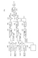
- FIG. 4 shows a baseband signal of a C / A (Coarse and Acquisition) code, which is a positioning signal that is put on the L1 band (1575.42 MHz) of the current GPS signal carrier among the circuits realized by the FPGA 245.
- the baseband signal of the L1C code which is a positioning signal used in the L1 band of a new positioning satellite system (for example, the Japanese Quasi-Zenith Satellite System), is modulated according to each signal format. It is a functional block diagram for demonstrating the structure of the modulator 245a for this.
- BPSK Binary Phase Shift Keying
- QPSK Quadrature Phase Shift Keying
- FIG. 4 is basically the configuration of a QPSK modulator, if the signal to be put on the I phase and the signal to be put on the Q phase are the same signal, as a result, A circuit configuration that can realize both BPSK modulation and QPSK modulation by utilizing the fact that it is equivalent to BPSK modulation.
- an independent circuit may be programmed for each method in accordance with the modulation method realized by the modulator 245a.
- modulator 245a includes PRN code registers 2462 and 2464 that receive and store the PRN code stored in EEPROM 243, and message data generating device 245b or message data generating device 245c as described later.
- Message code registers 2466 and 2468 for receiving and storing message data in accordance with the signal format of C / A code or L1C code from
- the PRN code set in the EEPROM 243 is input to the PRN code registers 2462 and 2464 from the outside.
- the message code registers 2466 and 2468 and the PRN code registers 2462 and 2464 are used. The same data is stored in each.
- the message code registers 2466 and 2468 and the PRN code registers 2462 and 2464 store data different in I-phase data and Q-phase data, respectively.
- the modulator 245a further multiplies the time series data read from the PRN code register 2462 and the time series data read from the message code register 2466, and the time series data and message code read from the PRN code register 2464.
- a multiplier 2454 that multiplies the time-series data read from the register 2468, a level control circuit 2456 that is controlled by the level control signal LVC 1 from the processor 241 and changes the intensity of the signal input from the multiplier 2452, and the processor 241. Is controlled by the level control signal LVC2 from the level control circuit 2458 and changes the intensity of the signal input from the multiplier 2454, and the output from the level control circuit 2456.
- FIR filter 2460 that functions as a bandpass filter having a bandwidth selected by the filter selection parameter, and FIR that functions as a bandpass filter having a bandwidth selected by the filter selection parameter with respect to the output from level control circuit 2458 And a filter 2461.
- the modulator 245a further generates a modulation reference clock according to the signal format based on the clock signal from the reference clock I / O block 230, and is synchronized with the signal from the clock circuit 2472 in advance.
- Look-up table 2474 for outputting data corresponding to the set sine wave and cosine wave as an I-phase modulation signal and a Q-phase modulation signal, and a signal corresponding to the sine wave output from lookup table 2574 and FIR From the multiplier 2463 that multiplies the signal from the filter 2460, the multiplier 2465 that multiplies the signal corresponding to the cosine wave output from the lookup table 2574 and the signal from the FIR filter 2461, and multipliers 2463 and 2465 Adder 2467 for adding the signals of And an output buffer 2470 for outputting the output from the adder 2467 is buffered to the D / A converter 247.
- the data included in the signal output from the modulator 245a to the D / A converter 247 as described above is as follows.
- the FPGA 245 firmware When the FPGA 245 firmware is configured to output a signal compatible with the current GPS signal (signal compatible with the L1 C / A code: L1 C / A compatible signal), the modulator 245 a For both the I-phase signal and the information on the latitude / longitude / height of the transmitter is modulated as a message, a BPSK-modulated signal is generated.
- the term “compatible signal” means a signal that can be received with a common front end unit as a receiver because it has a common signal format.
- the L1C signal from the satellite will be briefly described.
- the L1C signal from the satellite is QPSK-modulated, and the pilot signal for acquisition by the receiver is modulated on the Q-phase signal.
- the Q-phase signal is 3 dB higher than the I-phase signal.
- a navigation message or the like is carried on the I-phase signal.
- the reason why the pilot signal for acquisition is carried on the Q-phase signal is as follows.
- the C / A code of the current GPS signal is a 1023 chip signal with a 1 msec period, and the same signal continues for 20 periods, so that the S / N can be increased by integration, whereas the L1C signal Since 10230 is 10 msec period for 10230 chips, the S / N cannot be increased by integration because the same signal has only one period. Therefore, it is necessary to use the Q-phase signal of the signal from the satellite for capturing.
- the transmitter ID can be carried on the Q-phase signal.
- the intensity of the signal transmitted by the indoor transmitter 200 is stronger than the intensity of the signal transmitted from the GPS satellite, and thus no acquisition signal is required.
- the signal from the GPS satellite is weak when it propagates to the ground, so a signal for acquisition is required, whereas in the case of an indoor transmitter, the signal strength is to prevent multipath or unstable propagation. It is based on the situation that it is necessary to raise.
- position specifying data such as latitude / longitude / height data is placed on the I-phase signal.
- FIG. 5 is a diagram showing the spectral intensity distribution of the L1 C / A code signal and the L1C code signal.
- a P code which is a military code transmitted from a satellite together with a C / A code
- an M code signal mainly transmitted from a satellite together with an L1C signal.
- the spectral intensity is also shown.
- the L1C code has a null point at the center frequency of 1575.42 MHz in order to suppress interference with the C / A code, two main peaks on both sides, and a sidelobe signal on the outer side.
- the intensity of the signal at the point where the signal transmitted from the indoor transmitter 200 is received is larger than the signal intensity when the signal transmitted from the GPS satellite is received on the ground. Therefore, only the target frequency component is transmitted, and interference with other signals can be suppressed.
- FIG. 6 is a functional block diagram illustrating a configuration of the message data generation device 245b when the firmware of the FPGA 245 is set to transmit a signal compatible with the C / A code in the L1 band.
- the message data generation device 245b performs processing for placing position specifying data or the like given from the outside in a portion corresponding to the navigation message in the C / A code of the L1 band according to the signal format. is there.
- the message data generation device 245b reads the TOW (Time Of Week) information in the C / A code of the L1 band based on the command interface 2482 that receives the command 2480 from the processor 241 and the command given from the command interface 2482.
- a message bank 2490 for receiving and storing message information from the command interpreter 2488.
- the message bank 2490 includes 30-bit capacity banks 01 and 02 for storing TOW information, and 30-bit capacity banks 03 to 10 for storing message information.
- Each bank 01 to 10 has an area 2490a for storing information for 24 bits, and a CRC generator 2492 generates a CRC code (6 bits) for error detection from the data for 24 bits.
- the data is stored in an area 2490b following the area 2490a of each bank.
- the sequence counter 2494 sequentially provides read signals to the banks 01 to 10 in synchronization with the message clock (MSG Clock) based on the clock from the reference clock I / O block 230, and from the banks 01 to 10 in response to this. Are read out and stored in the message register 2496.
- MSG Clock message clock
- the data in the message register 2496 is written in both the message code registers 2466 and 2468. Subsequent processing is as described for the operation of the modulator 245a of FIG.
- FIG. 7 is a functional block diagram illustrating a configuration of the message data generation device 245c when the firmware of the FPGA 245 is set to transmit a signal compatible with the L1C code.
- the message data generating device 245c performs processing for placing position identification data, transmitter ID, and the like given from the outside in a portion corresponding to the navigation message and pilot signal in the L1C code according to the signal format. Is what you do.
- the message data generation device 245c includes a command interface 2502 that accepts a command 2500 from the processor 241, a message command interpreter 2504 for interpreting the content of data to be transmitted as a message based on the command given from the command interface 2502, A message bank 2506 that receives and stores message information for the I phase from the message command interpreter 2504 and a message bank 2508 that receives and stores message information for the Q phase from the message command interpreter 2504 are provided.
- the message bank 2506 includes banks I00 to I10 each having a capacity of 150 bits for storing information for I phase.
- the message bank 2508 includes 48-bit capacity banks Q00 to Q02 for storing Q-phase information, 63-bit capacity banks Q03 to Q05 for storing Q-phase information, Banks Q06 to Q08 each having a capacity of 75 bits for storing phase information are included. Note that the capacity of each bank for the Q phase is not limited to these values. For example, the capacity of the banks Q00 to Q08 can be set to 150 bits, which is the same capacity as the banks for the I phase. .
- a transmitter ID is stored in the message bank 2508 for the Q phase.
- the I-phase message bank 2506 includes not only the above-mentioned “position specifying data” but also “data for advertisement”, “traffic” given from the outside of the indoor transmitter 200 via the wireless I / F 210, for example.
- Information, “weather information” and “disaster information” can also be stored.
- the disaster information includes, for example, earthquake prediction and earthquake occurrence information.
- the above-mentioned “outside” includes a business apparatus that provides each of the above-mentioned information, a server device operated by a public office, or the like. Such information may be sent from the external server device in real time, or may be updated periodically.
- the operation manager of the indoor transmitter 200 may update the data as needed. For example, when each indoor transmitter 200 is installed in a department store, data for advertisement may be given to the indoor transmitter 200 by the operation manager as one of the sales activities of the department store.
- BCH error correction codes are added to data stored in banks Q00 to Q08, and error detection codes are added to data stored in banks I00 to I10. Can do.
- error detection codes are added to data stored in banks I00 to I10.
- the message data generation device 245c further responds to a command from the command interface 2502 and a sequence manager 2510 that reads data from the banks I00 to I10 for data included in the I-phase signal in a sequence according to the command from the command interface 2502. And a sequence manager 2512 that reads data from the banks Q00 to Q08 for the data included in the Q-phase signal.
- the message data generating device 245c sequentially reads data from the sequence manager 2510 and the sequence manager 2512 in synchronization with the message clock (MSG Clock) based on the clock from the reference clock I / O block 230, and separately, A message register 2514 for writing to the message code registers 2466 and 2468 is provided.
- the receiver side (position information providing device side) also has a 150-bit message bank I00 to I-phase on the I-phase transmitter side.
- the receiver side corresponds to each of I10, storage areas distinguished by I00 to I10 are provided, and corresponding to Q-phase message banks Q00 to Q08, storage areas distinguished by Q00 to Q08 are provided. It is assumed that By doing so, the contents of the storage area on the receiver side are updated each time any of the new data stored in the banks I00 to I10 or the banks Q00 to Q08 is received. For this reason, it is assumed that the data stored in the banks I00 to I10 and Q00 to Q08 includes an identifier that can identify which bank the data is.
- the messages generated by the message data generation device 245c are summarized for the messages transmitted from the indoor transmitter 200 as follows.
- a signal generated by the message data generation device 245c is referred to as an “L1C compatible message”.
- the L1C compatible message is composed of an I-phase signal and a Q-phase signal. Independent and separate messages are modulated on the I-phase signal and the Q-phase signal, respectively. Specifically, short information such as a transmitter ID is modulated in the Q-phase signal. Since the data length of the Q-phase signal is shorter than that of the I-phase signal, the receiver can quickly capture the Q-phase signal and acquire the ID immediately. However, since the ID has no meaning (for example, position information) by itself, the receiver cannot know the position only by the transmitter ID. Therefore, for example, the receiver accesses the site of the server device that provides the position information via the mobile phone network, transmits the transmitter ID to the server device, and transmits the position information associated with the transmitter ID to the server device. It is acquired from the server device.
- position specifying data is modulated in the I-phase signal.
- a configuration in which a message included in the I-phase signal is variable is possible.
- variable messages such as traffic information, weather information, and disaster information can be modulated on the I-phase signal.
- the I-phase signal includes the position information itself, the receiver user can know his / her position without connecting the receiver to the network. Therefore, for example, even when a disaster occurs and the communication line is congested, if the L1C compatible message can be received, the position of the receiver can be specified. In this case, if the receiver can transmit the position as a mobile phone, the receiver of the signal can easily specify the position of the transmitter (that is, the victim) of the signal.
- the I-phase signal and the Q-phase signal have a difference in the modulated information itself and a difference in configuration such as the length of the signal.
- the receiver only needs to be able to receive at least one of the signals in order to acquire the position information. Therefore, the user of the receiver can select which of the I-phase signal and the Q-phase signal is received as necessary. This selection is realized when the user inputs a setting that defines which signal is received to the receiver.
- the receiver may be automatically switched from the I-phase signal reception mode to the Q-phase signal reception mode when the connection to the server via the communication line fails due to timeout due to congestion of the communication line. .
- the C / A signal includes a PRN-ID and a message (for example, location information). Since the message can be updated in real time, the latest message can be included in the C / A signal.
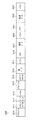
- FIG. 8 is a diagram showing a configuration of a signal 500 transmitted by a transmitter mounted on a GPS satellite.
- the signal 500 is composed of five 300-bit subframes, that is, subframes 510 to 550.
- Subframes 510 to 550 are repeatedly transmitted by the transmitter.
- Each of subframes 510 to 550 has, for example, 300 bits and is transmitted at a bit rate of 50 bps (bit per second). Therefore, in this case, each subframe is transmitted in 6 seconds.
- the first subframe 510 includes 30-bit TOH 511, 30-bit time information 512, and 240-bit message data 513.
- the time information 512 includes time information acquired when the subframe 510 is generated, and a subframe ID.
- the subframe ID is an identification number for distinguishing the first subframe 510 from other subframes.
- the message data 513 includes a GPS week number, clock information, health information of the GPS satellite, orbit accuracy information, and the like.
- the second subframe 520 includes 30-bit TOH 521, 30-bit time information 522, and 240-bit message data 523.
- the time information 522 has the same configuration as the time information 512 in the first subframe 510.
- the message data 523 includes ephemeris (ephemeris, broadcast calendar).
- the ephemeris refers to orbit information of a satellite that transmits a positioning signal.
- the ephemeris is highly accurate information that is sequentially updated by a control station that manages the navigation of the satellite.
- the third subframe 530 has the same configuration as the second subframe 520. That is, the third subframe 530 includes 30-bit TOH 531, 30-bit time information 532, and 240-bit message data 533.
- the time information 532 has the same configuration as the time information 512 in the first subframe 510.
- the message data 533 includes an ephemeris.
- the fourth subframe 540 includes 30-bit TOH 541, 30-bit time information 542, and 240-bit message data 543.
- the message data 543 includes almanac information, satellite health information summary, ionospheric delay information, UTC (Coordinated Universal Time) parameters, and the like.
- the fifth subframe 550 includes 30-bit TOH 551, 30-bit time information 552, and 240-bit message data 553.
- Message data 553 includes almanac information and a summary of satellite health information.
- Each of the message data 543 and 553 is composed of 25 pages, and the above different information is defined for each page.
- the almanac information is information representing a general orbit of a satellite, and includes information on all GPS satellites as well as the satellite.
- Subframes 510 to 550 are transmitted from transmitters 120, 121, and 122, respectively.
- the position of the position information providing apparatus 100 includes the maintenance / management information included in the TOHs 511 to 551, time information 512 to 552, and message data 513 to 553 and is calculated.
- the signal 560 has the same data length as the message data 513 to 553 included in the subframes 510 to 550. Signal 560 differs from subframes 510-550 in that it has data representing the location of the source of signal 560 in place of orbit information represented as ephemeris (message data 523, 533).
- the signal 560 includes a 6-bit PRN-ID 561, a 15-bit transmitter ID 562, an X coordinate value 563, a Y coordinate value 564, a Z coordinate value 565, an altitude correction coefficient (Zhf) 566, an address 567 and a reserve area 568.
- Signal 560 is transmitted from indoor transmitters 200-1, 200-2, 200-3 in place of message data 513-553 included in subframes 510-550.
- PRN-ID 561 is an identification number of a code pattern of a group of pseudo-noise codes assigned in advance to a transmitter (for example, indoor transmitters 200-1, 200-2, 200-3) that is a transmission source of signal 560. It is.
- the PRN-ID 561 is different from the identification number of the code pattern of a group of pseudo-noise codes assigned to each transmitter mounted on each GPS satellite, but the PRN-ID 561 is a code pattern generated from a code string of the same series. It is the number assigned to it.
- the position information providing apparatus obtains one of the code patterns of the pseudo-noise code assigned for the indoor transmitter from the received signal 560, so that the signal is transmitted in the subframes 510 to 550 transmitted from the satellite. It is specified whether there is a signal 560 transmitted from an indoor transmitter.
- the X coordinate value 563, the Y coordinate value 564, and the Z coordinate value 565 are data representing the position where the indoor transmitter 200 is attached.
- the X coordinate value 563, the Y coordinate value 564, and the Z coordinate value 565 are represented, for example, as latitude, longitude, and altitude.
- the altitude correction coefficient 566 is used to correct the altitude specified by the Z coordinate value 565.
- the altitude correction coefficient 566 is not an essential data item. Therefore, when the accuracy higher than the altitude specified by the Z coordinate value 565 is not required, the coefficient may not be used. In this case, for example, data representing “NULL” is stored in the area allocated for altitude correction coefficient 566.
- FIG. 9 is a diagram illustrating a first configuration of the L1C compatible signal.
- a signal 810 is transmitted by the transmitter.
- the signal 810 includes a 30-bit TOH 811, a 30-bit time information 812, a 6-bit PRN-ID 813, a 15-bit transmitter ID 814, an X coordinate value 815, a Y coordinate value 816, and a Z coordinate value 817.
- the first 60 bits of signal 810 are identical to the first 60 bits of each of subframes 510-550 transmitted by a GPS satellite.
- the signal 820 is transmitted by the transmitter as the second subframe.
- Signal 820 includes a 6-bit subframe ID 821, an altitude correction factor 822, and a transmitter location address 823.
- the information included in each subframe is not limited to the above. For example, advertisements related to location information, Internet site URLs (Uniform Resource Locators), and the like may be stored in a predefined area in each subframe.
- Signals 830 to 870 indicate transmission examples of third to sixth subframes having the same structure as the signals 810 and 820 and the signal 820 described above. That is, the signal 830 includes a first subframe 831 and a second subframe 832. The first subframe 831 has the same header as the subframes 510 to 550 transmitted from the GPS satellite. Second subframe 832 is a frame corresponding to signal 820.
- the signal 840 includes a first subframe 831 and a third subframe 842.
- the first subframe 831 is the same as the first subframe 831.
- the third subframe has the same structure as signal 820.
- Signal 870 includes a first subframe 831 and a sixth subframe 872.
- the first subframe 831 is transmitted every time each signal is transmitted. After the first subframe 831 is transmitted, any other subframe is interpolated. That is, the transmission order of each subframe is as follows: first subframe 831 ⁇ second subframe 832 ⁇ first subframe 831 ⁇ third subframe 842 ⁇ first subframe ⁇ . 6 subframes 872 ⁇ first subframe 831 ⁇ second subframe 832...
- FIG. 10 is a diagram illustrating a second configuration of the L1C compatible signal.
- the structure of the message data may be defined independently of the subframes 510 to 550.
- FIG. 10 is a diagram conceptually showing the second configuration of the L1C compatible signal 910.
- an L1C compatible signal 910 includes TOH 911, preamble 912, PRN-ID 913, transmitter ID 914, first variable 915, X coordinate value 916, Y coordinate value 917, Z A coordinate value 918 and a parity / CRC 919 are included.
- the signal 920 has the same configuration as the L1C compatible signal 910.
- a second variable 925 is included instead of the first variable 915 in the L1C compatible signal 910.
- Each signal has a length of 150 bits. Six signals having the same structure are transmitted. You may comprise the signal which has such a structure as a signal transmitted from an indoor transmitter.
- the location information providing apparatus 100 can specify the transmission source of the received signal based on the PRN-ID. If the transmission source is an indoor transmitter, the signal includes an X coordinate value, a Y coordinate value, and a Z coordinate value. Therefore, the position information providing apparatus 100 can display the indoor position.
- ⁇ Signal format> The format of the signal transmitted by indoor transmitter 200 or a GPS satellite according to the present embodiment is not limited to the above-described mode. Therefore, another format will be described with reference to FIGS.
- FIG. 11 is a diagram conceptually showing the format of an L1C / A signal composed of three words.
- This signal includes a first word 3010, a second word 3020, and a third word 3030. Each word is 30 bits long.
- the message type of this signal is “0”, for example.
- the first word 3010 includes an 8-bit preamble 3011, 3-bit message type ID 3012, 8-bit floor data 3013, 2-bit latitude (LSB) 3014, 3-bit longitude (LSB) 3015, 6 Bit parity 3016.
- the second word 3020 includes a 3-bit CNT 3021, a 21-bit latitude (MSB) 3022, and a 6-bit parity 3023.
- the third word 3030 includes a 3-bit CNT 3031, a 21-bit latitude (MSB) 3032, and a 6-bit parity 3033.
- FIG. 12 is a diagram conceptually showing the format of an L1C / A signal composed of 4 words.
- This signal includes a first word 3110, a second word 3120, a third word 3130, and a fourth word 3140. Each word is 30 bits long.
- the message type of this signal is “1”, for example.
- the first word 3110 includes an 8-bit preamble 3111, a 3-bit message type ID 3112, a 9-bit floor data 3113, a 4-bit reserve 3114, and a 6-bit parity 3115.
- the second word 3120 includes a 3-bit CNT 3121, a 21-bit latitude (MSB) 3122, and a 6-bit parity 3123.
- the third word 3130 includes a 3-bit CNT 3131, a 21-bit latitude (MSB) 3132, and a 6-bit parity 3133.
- the fourth word 3140 includes a 3-bit CNT 3141, a 12-bit altitude 3142, a 2-bit reserve 3143, a 3-bit latitude (LSB) 3144, a 3-bit longitude (LSB) 3145, and a 6-bit parity. 3146.
- FIG. 13 conceptually shows a format of L1C / A signal 3200 including a short ID.
- the message type of the signal 3200 is “3”, for example.
- the signal 3200 includes an 8-bit preamble 3220, a 3-bit message type ID 3220, a 12-bit short ID (SID) 3230, a 1-bit BD 3240, and a 6-bit parity 3250.
- FIG. 14 is a diagram conceptually showing a format of an L1C / A signal including a medium ID.
- the message type of this signal is “4”, for example.
- This signal includes a first word 3310 and a second word 3320.
- the first word 3310 includes an 8-bit preamble 3311, a 3-bit message type ID 3312, a 12-bit short ID (IDM) (MSB) 3313, a 1-bit BD 3314, and a 6-bit parity 3315.
- Second word 3320 includes 3-bit CNT 3321, 21-bit medium ID (MID) (LSB) 3322, and 6-bit parity 3323.
- FIG. 15 is a diagram illustrating a frame configuration configured according to the number of words. Each word is 30 bits in length.
- the frame 3410 consists of one word.
- the frame 3410 includes an 8-bit preamble 3411, a 3-bit message type ID 3412, a 13-bit data bit 3413, and a 6-bit parity 3414.
- the frame 3420 consists of 2 words.
- the first word of frame 3420 includes an 8-bit preamble 3421, a 3-bit message type ID 3422, a 13-bit data bit 3423, and a 6-bit parity 3424.
- the second word of frame 3420 includes a 3-bit CNT 3425, a 21-bit data bit 3426, and a 6-bit parity 3427.
- Frame 3430 consists of 3 words.
- the first word of frame 3430 includes an 8-bit preamble 3431, a 3-bit message type ID 3432, a 13-bit data bit 3433, and a 6-bit parity.
- the second word of frame 3430 includes 3-bit CNT 3435, 21-bit 3436, and 6-bit parity 3437.
- the third word of frame 3430 includes a 3-bit CNT 3438, a 21-bit data bit 3439, and a 6-bit parity 3440.
- FIG. 16 is a diagram conceptually showing a frame 3500 including a short ID and position information.
- the first word of the frame 3500 includes a preamble 3510, a message type ID 3512, a data bit 3512, and a parity 3513.
- the second word includes a preamble 3514, a message type ID 3515, floor data 3516, and parity 3517.
- the third word includes CNT 3518, latitude data 3519, and parity 3520.
- the fourth word includes CNT 3521, longitude data 3522, and parity 3523.
- the position information is composed of the second to fourth words.
- the format of the signal transmitted from the indoor transmitter 200 is not limited to one, and may be various formats.
- a transmitter ID that is an identifier for identifying the position of the indoor transmitter 200 is transmitted as a short ID (hereinafter referred to as SID).
- SID short ID
- the data format for transmitting the identifier for identifying the position of the indoor transmitter 200 is not limited to the SID, and for example, a medium ID or the like may be used.
- the position information providing device which is a receiver in the shortest time It is expected to be acquired on the 100 side.
- An outline of indoor positioning performed by the indoor transmitter 200 and the position information providing apparatus 100 according to Embodiment 1 is as follows.
- An SID is an indirect reference identifier that cannot be resolved by itself, and cannot be distributed and used as a global identifier due to restrictions on the number of bits. Therefore, the SID is used as a local identifier and is issued / managed in advance so that the uniqueness is guaranteed in individual “facility units” (for example, building units) which are actual transmitter installation / management units.
- the SID issued / managed by each facility is associated with the location of each indoor transmitter using the ID base on the indoor map data generated by SVG as an intermediary (ie, creating a conversion table)
- the SVG map information provided to the position information providing apparatus 100 is superimposed / included (hereinafter, the SVG map information including such a conversion table is referred to as “SVG container”).
- a shortened URL is transmitted using a signal of message type 4, and the SVG container (indoor map + information layer + SID conversion table) is transmitted to the user location information providing apparatus 100 ( The current location display on the indoor map and the SID conversion table are stored on the position information providing apparatus 100).
- the indoor transmitter and the terminal do not refer to the external server and perform location resolution only by the terminal.
- the indoor transmitter and the terminal do not refer to the external server and perform location resolution only by the terminal.
- FIG. 17 is a block diagram showing a hardware configuration of position information providing apparatus 100.
- the position information providing apparatus 100 includes an antenna 402, an RF (Radio Frequency) front circuit 404 electrically connected to the antenna 402, a down converter 406 electrically connected to the RF front circuit 404, and a down converter An A / D (Analog to Digital) converter 408 electrically connected to 406, a baseband processor 412 that receives a signal from the A / D converter 408, performs correlation processing, and is electrically connected to the baseband processor 412 A memory 420 connected to the baseband processor 412, a navigation processor 430 electrically connected to the baseband processor 412, and a display 440 electrically connected to the navigation processor 430.
- RF Radio Frequency
- the baseband processor 412 includes correlators 410.1 to 410. electrically connected to the A / D converter 408. n and correlators 410.1-410. n Numerically Controlled Oscillators (NCO) 411.1 to 411 for supplying a clock as a reference for timing of correlation processing. n and correlators 410.1-410. n, which respectively receive signals from n and perform integration processing for a predetermined period. n.
- NCO Numerically Controlled Oscillators
- the baseband processor 412 further adds the accumulators 412.1 to 412. based on the software stored in the memory 420. n and the correlator 410.1-410. n, NCO 411.1-411. n and integrators 412.1-412.
- movement of n is included.
- the baseband processor 412 performs correlation processing in consideration of the influence of the Doppler effect of the received signal, and performs not only a search for the PRN code and its delay component but also the NCO 411 according to the control of the control unit 414. 1-41.
- the frequency search is also performed by controlling the frequency of n.
- the correlators 410.1 to 410. n, and integrators 412.1-412. n may be configured to be hardware independent of the baseband processor 412.
- the function with n can also be realized as software.
- the memory 420 includes a plurality of areas for storing a PRN code pattern, which is data for identifying each transmission source of the positioning signal.
- a PRN code pattern which is data for identifying each transmission source of the positioning signal.
- the memory 420 when 48 code patterns are used, the memory 420 includes regions 421-1 to 421-48 as shown in FIG. In another aspect, when more code patterns are used, more area is secured in the memory 420. Conversely, a code pattern that is smaller than the number of areas reserved in the memory 420 may be used.
- the code pattern of the pseudo-noise code for the first satellite is stored in area 421-1. From this, the code pattern is read out, and the cross-correlation process with the received signal is performed, whereby the signal can be tracked and the navigation message included in the signal can be decoded.
- the method of storing and reading the code pattern is exemplarily shown, but a method of generating a code pattern by a code pattern generator is also possible.
- the code pattern generator is realized, for example, by combining two feedback shift registers. It should be noted that the configuration and operation of the code pattern generator can be easily understood by those skilled in the art. Therefore, detailed description thereof will not be repeated.
- the code pattern of the pseudo-noise code assigned to the indoor transmitter that transmits the positioning signal is stored in areas 421-37 to 421-48.
- the code pattern of the assigned pseudo-noise code for the first indoor transmitter is stored in areas 421-37 and 421-48.
- PRN code spreading code
- an indoor transmitter having 12 code patterns can be used, but there is no indoor transmitter that uses the same code pattern in a range that can be received by the same position information providing apparatus.
- each indoor transmitter may be arranged. By doing so, it is possible to install six or more indoor transmitters on the same floor of the building 130, for example.
- the navigation processor 430 determines the source of the positioning signal based on the data output from the control unit 414, and determines whether the received positioning signal is a diversity transmission, and controls the operation of the control unit 414.
- An outdoor positioning unit 432 for measuring the position of the outdoor location information providing apparatus 100 based on a signal output from the determination unit 416 based on software stored in the memory 420, and a determination unit
- an indoor positioning unit 434 for deriving information representing the position of the position information providing apparatus 100 indoors based on the data output from 416.
- the antenna 402 can receive the positioning signals transmitted from the GPS satellites 110, 111, and 112 and the positioning signals transmitted from the indoor transmitter 200-1.
- the antenna 402 can transmit and receive a signal for wireless telephone or a signal for data communication in addition to the above-described signal.
- the filter of the RF front circuit 404 and the LNA (Low Noise Amplifier) circuit receive a signal received by the antenna 402 and perform noise reduction or filter processing for outputting only a signal having a predetermined bandwidth.
- a signal output from the RF front circuit 404 is input to the down converter 406.
- the down converter 406 amplifies the signal output from the RF front circuit 404 and outputs it as an intermediate frequency. This signal is input to the A / D converter 408.
- the A / D converter 408 performs digital conversion processing on the input intermediate frequency signal and converts it into digital data.
- the digital data is stored in the correlator 410.1-410. n.
- Correlator 410.1-410. n performs a correlation process between the code pattern read out from the memory 420 by the control unit 414 and the received signal.
- Correlator 410.1-410 Each of the n correlators simultaneously executes matching between the received positioning signal and a code pattern generated for demodulating the positioning signal based on the control signal output from the control unit 414.
- the control unit 414 includes the correlators 410.1 to 410.
- a command for generating a code pattern (replica pattern) reflecting a delay that may occur in the pseudo-noise code (shifting the code phase) is given to each of n.
- This command is, for example, the number of satellites ⁇ 2 ⁇ 1023 (the length of the code pattern of the pseudo-noise code used) in the current GPS.
- Each correlator 410.1-410. n generates code patterns having different code phases using a code pattern of a pseudo-noise code defined for each satellite based on a command given to each. Then, one of all the generated code patterns matches the code pattern of the pseudo noise code used for modulation of the received positioning signal.
- the number of correlators necessary for performing the matching process using each code pattern is converted into parallel correlators 410.1 to 410.
- the code pattern of the pseudo-noise code can be specified in a very short time. This processing can be similarly applied when the position information providing apparatus 100 receives a signal from an indoor transmitter. Therefore, even when the user of the position information providing apparatus 100 is indoors, the position information can be acquired in a very short time.
- the parallel correlators 410.1 to 410. n can be matched in parallel at the maximum for all of the code pattern of the pseudo-noise code specified for each satellite and the code pattern of the pseudo-noise code specified for each indoor transmitter. .
- all of the code patterns of pseudo-noise codes specified for each satellite and each indoor transmitter are as follows: Even when matching is not performed collectively, the time required to acquire the position information can be greatly shortened by parallel processing using a plurality of correlators.
- the satellite and the indoor transmitter transmit signals by the spread spectrum method which is the same communication method
- the pseudo-noise code patterns assigned to the satellite and the indoor transmitter can be used in the same series.
- the parallel correlator can be shared for both the signal from the satellite and the transmission from the indoor transmitter, and the reception processing can be performed in parallel without specially distinguishing between the two.
- Parallel correlators 410.1-410. n uses each code pattern to track the positioning signal received by the position information providing apparatus 100 and to perform processing for specifying a code pattern having an arrangement that matches the bit arrangement of the positioning signal.
- the determination unit 416 specifies the code pattern of the pseudo-noise code, so that the position information providing apparatus 100 transmits the received positioning signal from which satellite or the indoor transmitter. Can be determined.
- the determining unit 416 also determines whether or not the positioning signal is diversity-transmitted. Further, the position information providing apparatus 100 can demodulate and decode the message using the specified code pattern.
- the determination unit 416 performs the determination as described above, and sends data corresponding to the determination result to the navigation processor 430.
- the determination unit 416 determines whether the PRN-ID included in the received positioning signal is a PRN-ID assigned to the indoor transmitter 200-1 other than the transmitter mounted on the GPS satellite.
- a spare code for example, 36 pseudo-noise codes are used.
- PRN-01 to PRN-24 are used as numbers for identifying each GPS satellite (PRN-ID)
- PRN-25 to PRN-36 are used as numbers for identifying spare satellites.
- the spare satellite is a satellite that is newly launched in addition to the satellite that was originally launched. That is, such a satellite is launched in preparation for a failure of a GPS satellite or a transmitter mounted on the GPS satellite.
- 12 pseudo-noise code patterns are assigned to indoor transmitters 200-1 other than the transmitters mounted on the GPS satellites.
- a number different from the PRN-ID assigned to the satellite for example, PRN-37 to PRN-48 is assigned to each transmitter. Therefore, in this example, 48 PRN-IDs exist.
- PRN-ID to PRN-48 are assigned to the indoor transmitters according to the arrangement of the indoor transmitters, for example. Therefore, if a transmission output that does not interfere with signals transmitted from each indoor transmitter is used, the same PRN-ID may be used for different indoor transmitters. With such an arrangement, more transmitters can be used than the number of PRN-IDs allocated for terrestrial transmitters.
- the determination unit 416 refers to the code pattern 422 of the pseudo-noise code stored in the memory 420, and converts the code pattern acquired from the received positioning signal into the code pattern assigned to the indoor transmitter. Determine whether they match. If these code patterns match, the determination unit 416 determines that the positioning signal is transmitted from the indoor transmitter. If not, the determination unit 416 determines that the signal is transmitted from a GPS satellite, and stores in the memory 420 which satellite the allocated code pattern is the code pattern assigned to. It is determined with reference to the code pattern. Although an example in which a code pattern is used is shown as an aspect of determination, the above determination may be made by comparing other data. For example, a comparison using PRN-ID may be used for the determination.
- the determination unit 416 sends data acquired from the specified signal to the outdoor positioning unit 432.
- the data obtained from the signal includes a navigation message.
- determination unit 416 sends the data acquired from the signal to indoor positioning unit 434.
- This data is a coordinate value set in advance as data for specifying the position of the indoor transmitter 200-1.
- a number that identifies the transmitter may be used.
- the outdoor positioning unit 432 executes a process for calculating the position of the position information providing apparatus 100 based on the data sent from the determination unit 416. Specifically, the outdoor positioning unit 432 calculates the propagation time of each signal using data included in signals transmitted from three or more GPS satellites (preferably four or more), and the calculation result Based on the above, the position of the position information providing apparatus 100 is calculated. This process is executed using a known satellite positioning method. This process can be easily understood by those skilled in the art. Therefore, details of the description will not be repeated here.
- the indoor positioning unit 434 performs a positioning process when the position information providing apparatus 100 exists indoors based on the data output from the determination unit 416.
- indoor transmitter 200-1 transmits a positioning signal including data for specifying a location (position specifying data). Therefore, when the position information providing apparatus 100 receives such a signal, data included in the signal can be extracted and the position of the position information providing apparatus 100 can be derived using the data.
- the indoor positioning unit 434 performs this process.
- a map drawing processing unit using data calculated by the outdoor positioning unit 432 or the indoor positioning unit 434 and based on the SVG map information already stored in the memory 420 or the SVG map information received via the communication unit 450 436 generates and outputs an image signal for displaying the current position of the position information providing apparatus 100 on the display 440. Specifically, these data are incorporated into the data for displaying the screen, and an image representing the measured position or an image for displaying the place where the indoor transmitter 200-1 is installed is generated. Displayed on the display 440.
- the map drawing processing unit 436 has a function as a browser for displaying a map from the SVG map information.
- the position information providing apparatus 100 includes a communication unit 450 for exchanging data with the outside, for example, with a position information providing server (not shown) under the control of the control unit 414. .
- the antenna 402 in signal processing from reception of a positioning signal to generation of information displayed on the display, the antenna 402, the RF front circuit 404, the down converter 406, and the A / D converter 408 are: It is configured by hardware, and the processing of the baseband processor 412 and the navigation processor 430 can be executed by a program stored in the memory 420.
- FIG. 18 is a diagram illustrating a usage mode of position information providing apparatus 100 according to the present embodiment.
- the position information providing apparatus is realized as a mobile phone 1200.
- the cellular phone 1200 can receive a positioning signal transmitted by the indoor transmitter 1210.
- Indoor transmitter 1210 is connected to the Internet 1220.
- An information providing server 1230 that can provide information on the indoor transmitter 1210 is connected to the Internet 1220.
- a base station 1240 that communicates with the mobile phone 1200 is also connected to the Internet 1220.
- the transmitter ID for identifying the indoor transmitter 1210 is acquired from the signal.
- the transmitter ID is associated with, for example, the aforementioned PRN-ID.
- the cellular phone 1200 transmits the transmitter ID (or along with the PRN-ID) to the information providing server 1230. Specifically, the mobile phone 1200 starts communication with the base station 1240 and sends packet data including the acquired transmitter ID to the information providing server 1230.
- the information providing server 1230 When the information providing server 1230 recognizes the transmitter ID, the information providing server 1230 refers to the database associated with the transmitter ID and reads the SVG map information related to the ID. When the information providing server 1230 transmits the data of the SVG map information to the base station 1240, the base station 1240 wirelessly transmits the data of the SVG map information. When the mobile phone 1200 detects the arrival of the data, the location of the indoor transmitter 1210 can be acquired from the data according to the browsing operation by the user of the mobile phone 1200.
- FIG. 19 is a diagram showing a comparison between SVG map information data (SVG container) and a map image displayed by the SVG map information data.
- the SVG map information data includes the following information.
- Attribute information of a drawing indicating association between the data of the SVG map information and geographic coordinates. That is, it is information for specifying the positional relationship between a map representing the outdoors and a building having the floor.
- Information indicating the shape of the outline of the floor is information for specifying the positional relationship between a map representing the outdoors and a building having the floor.
- Information indicating the shape of the outline of the floor is information for specifying the positional relationship between a map representing the outdoors and a building having the floor.
- Information indicating the shape of the outline of the floor indicating the shape of the sections in the floor.
- Attribute information of each indoor transmitter installed on the floor. ID of the indoor transmitter and position information of the indoor transmitter in the floor (position identifier and position coordinates in the indoor map). This information corresponds to a conversion table between the SID and the position of the indoor transmitter.
- FIG. 20 is a flowchart showing a procedure of processes executed by baseband processor 410 and navigation processor 430 of position information providing apparatus 100.
- the position information providing apparatus 100 acquires (tracks and captures) a positioning signal.
- the baseband processor 410 receives an input of a received positioning signal (data after digital conversion processing) from the A / D converter 408.
- the baseband processor 410 generates code patterns having different code phases that reflect possible delays as replicas of the pseudo-noise code, and detects the presence or absence of correlation between the code pattern and the received positioning signal.
- the number of generated code patterns is, for example, twice the number of bits of the code pattern. As an example, for example, when the chip rate is 1023 bits, 2046 code patterns having a delay of 1 ⁇ 2 bit, that is, a code phase difference may be generated.
- the baseband processor 410 may lock the code pattern and specify the satellite that has transmitted the positioning signal based on the code pattern when an output exceeding a predetermined strength is detected in the correlation processing. it can. There is only one pseudo-noise code having the bit pattern of the code pattern. As a result, the pseudo-noise code used for spread spectrum encoding of the received positioning signal is specified.
- the baseband processor 410 specifies the source of the positioning signal. Specifically, the determination unit 416 determines the source of the signal based on the PRN-ID associated with the transmitter that uses the code pattern of the pseudo-noise code used during modulation to generate the signal. Identify. If the positioning signal is transmitted from the outdoors, control is transferred to step S620. If the positioning signal is transmitted indoors, the control moves to step S630. If the plurality of received signals include those transmitted from outdoors and indoors, control is transferred to step S640.
- step S620 the position information providing apparatus 100 acquires data included in the signal by demodulating the positioning signal.
- the outdoor positioning unit 432 of the navigation processor 430 uses the code pattern temporarily stored in the memory 420 for the positioning signal (the code pattern in which the above-described “lock” is performed, hereinafter “lock”).
- the navigation message is acquired from the subframes constituting the signal by superimposing using the above-described code pattern ").
- outdoor positioning unit 432 executes normal navigation message processing for calculating a position using the acquired four or more navigation messages.
- step S624 the outdoor positioning unit 432 executes a process for calculating the position of the position information providing apparatus 100 based on the result of the process. For example, when the position information providing apparatus 100 receives each positioning signal transmitted from four or more satellites, the distance is calculated by calculating the orbit of each satellite included in the navigation message demodulated from each signal. Information, time information, etc. are used.
- position information providing apparatus 100 when position information providing apparatus 100 receives a positioning signal (outdoor signal) transmitted by a satellite and a signal from an indoor transmitter (indoor signal) in step S612, In step S640, position information providing apparatus 100 obtains data included in the signal by demodulating the positioning signal. Specifically, the outdoor positioning unit 432 obtains data in subframes constituting the positioning signal by superimposing the locked code pattern on the positioning signal transmitted by the baseband processor 410. In this case, the position information providing apparatus 100 receives the signal from the satellite and the signal from the indoor transmitter, and thus operates in the “hybrid” mode. Therefore, a navigation message having time data is acquired for the signal from each satellite, and data having the above coordinate values and other position information is acquired for the signal from the indoor transmitter.
- step S642 the indoor positioning unit 434 performs processing for acquiring the X coordinate value 563, the Y coordinate value 564, and the Z coordinate value 565 from the positioning signal transmitted by the indoor transmitter 200-1.
- a navigation message is acquired from the positioning signal transmitted by the GPS satellite and processed.
- control is transferred to step S624.
- step S624 sorting for determining a signal used for position calculation is performed based on, for example, the intensity of an indoor signal and an outdoor signal. As an example, when the intensity of the indoor signal is greater than the intensity of the outdoor signal, the indoor signal is selected, and the coordinate value included in the indoor signal is set as the position of the position information providing apparatus 100.
- step S612 if the source of the positioning signal is indoors in step S612, for example, if the intensity of the indoor signal is a predetermined level or higher, then indoor positioning processing is performed in step S630.
- the determination unit 416 determines whether the Q-phase signal reception mode is set. If the Q-phase signal reception mode is not set (for example, L1 C / A reception mode or L1C I-phase signal reception mode), the position information providing apparatus 100 then demodulates the positioning signal to Get the data contained in the signal. Specifically, the indoor positioning unit 434 acquires message data from the subframes constituting the positioning signal by superimposing the locked code pattern on the positioning signal transmitted from the baseband processor 410. . This message data is included in the positioning signal transmitted by the indoor transmitter instead of the navigation message included in the positioning signal transmitted from the satellite. The format of the message data is therefore preferably the same format as that of the navigation message.
- the indoor positioning unit 434 acquires coordinate values (that is, data for specifying the installation location of the indoor transmitter (for example, the X coordinate value 563, the Y coordinate value 564, and the Z coordinate value 565 in the signal 560)) from the data. To do. If the frame includes text information representing the installation location or the address of the installation location instead of such coordinate values, the text information is acquired.
- coordinate values that is, data for specifying the installation location of the indoor transmitter (for example, the X coordinate value 563, the Y coordinate value 564, and the Z coordinate value 565 in the signal 560)
- step S636 the position information providing apparatus 100 demodulates the positioning signal, so that the data (transmitter ID) included in the signal is demodulated. ) To get.
- step S638 the position information providing apparatus 100 receives the SVG map information data corresponding to the transmitter ID from the server (not shown) by transmitting the transmitter ID via the network.
- step S650 the map drawing processing unit 436 executes processing for displaying position information on the display 440 based on the position calculation result. Specifically, image data for displaying the acquired coordinates or data for displaying the installation location of the indoor transmitter 200-1 is generated and sent to the display 440. The display 440 displays the position information of the position information providing apparatus 100 in the display area based on such data.
- FIG. 21 is a diagram conceptually showing a process in the case of presenting position information based on the transmitter ID (SID) and SVG map information data from the server in the indoor positioning process (S630) of FIG. is there.
- the position information providing apparatus 100 will be described as a mobile device such as a mobile phone.
- indoor transmitter 200 when indoor transmitter 200 enters an indoor facility, it transmits a shortened URL using a signal of message type 4 at the entrance / inside of the facility, and the SVG container (indoor map + information). Layer + SID conversion table) is transmitted to the user location information providing apparatus 100.
- position information providing apparatus 100 After entering the indoor facility, if it is determined that the current positioning signal transmission source is indoor transmitter 200, first, in position information providing apparatus 100, the indoor functioning as an indoor positioning module is performed.
- the positioning unit 434 determines the identifier transmitted from the indoor transmitter, and notifies the identifier / trajectory information module in the map drawing processing unit 436. Based on the identifier (transmitter ID (SID)) notified from the identifier / orbit information module, the web browser module in the map drawing processing unit 436 determines the identifier from the data on the information providing server 1230 specified by the URL. And SVG map information including a conversion table of indoor transmitter attribute information corresponding to the identifier is received via a network (for example, the Internet).
- a network for example, the Internet
- the web browser module displays the SVG map as a web browser on the display 440 and also displays the position of the indoor transmitter that has received the identifier on the SVG map.
- the terminal After obtaining the SVG map information locally in the location information providing apparatus 100, the terminal is used without referring to the external server on the indoor transmitter and terminal side using the conversion table stored locally.
- the conversion table stored locally By simply resolving the location, updating the current location of the indoor map and updating the neighborhood information, high-speed continuous positioning / information distribution that follows the moving speed (eg walking speed) of a human being, etc., is realized.
- the indoor transmitter corresponds to the identifier of each indoor transmitter.
- Information for identifying a PRN code (spreading code) at the time of spread spectrum modulation in the transmitter can also be included.
- ID information of the PRN code can be used.
- downloading a map means not only identifiers for indoor transmitters near the entrance of the facility, but also identifiers for indoor transmitters in the vicinity (for example, multiple indoor transmitters on the same floor). Therefore, the information can be grasped as information in advance at the receiver side. In this case, when the positioning signal is captured on the receiver side, it is also assisted which of the spreading codes should be used to supplement, and it becomes possible to capture the positioning signal at a higher speed. .
- the SVG map information includes a conversion table between the identifier of the indoor transmitter transmitted from the indoor transmitter and the position information of the indoor transmitter.
- the position information providing apparatus 100 is configured to acquire orbit information of positioning satellites used for outdoor positioning when acquiring SVG map information.
- the position information providing apparatus 100 starts from a state without trajectory information (cold start)
- smooth positioning is required because it takes time to acquire satellite data during handover from indoor to outdoor. Is difficult to deliver.
- it is possible to download the positioning satellite orbital information when acquiring map information indoors positioning accuracy will be improved when performing positioning handover from indoor to outdoor. And the positioning time can be shortened.
- FIG. 22 shows the indoor positioning process based on the identifier of the indoor transmitter from the indoor transmitter and the SVG map information data from the server, and the outdoor positioning using the orbit information received together with the SVG map information data. It is a figure which shows a process notionally.
- the position information providing apparatus 100 will be described as a mobile device such as a mobile phone.
- the SVG container data distribution of the first embodiment is performed in order to solve the problems of the positioning accuracy and the positioning time that are deteriorated when moving from indoor to outdoor.
- satellite orbit data is also distributed.
- an orbit information database for providing orbit information of positioning satellites is provided on the Internet.
- the information providing server web server acquires trajectory information determined by the location indicated by the SVG map to be distributed and the current time from the trajectory information database.
- the indoor transmitter 200 when entering the indoor facility, transmits a shortened URL using a signal of message type 4 at the facility entrance / inside, and the SVG container ( Indoor map + information layer + SID conversion table) is transmitted to the user location information providing apparatus 100.
- the SVG container Indoor map + information layer + SID conversion table
- position information providing apparatus 100 After entering the indoor facility, if it is determined that the current positioning signal transmission source is indoor transmitter 200, first, in position information providing apparatus 100, the indoor functioning as an indoor positioning module is performed.
- the positioning unit 434 determines the identifier transmitted from the indoor transmitter, and notifies the identifier / trajectory information module in the map drawing processing unit 436. Based on the identifier (transmitter ID (SID)) notified from the identifier / orbit information module, the web browser module in the map drawing processing unit 436 determines the identifier from the data on the information providing server 1230 specified by the URL. And SVG map information including a conversion table of indoor transmitter attribute information corresponding to the identifier is received via a network (for example, the Internet).
- a network for example, the Internet
- the SVG container (URL) of the building to be acquired is determined, the location of the facility to be subject to indoor positioning (such as the latitude and longitude coordinates of the facility representative point) and the time are specified, and satellite positioning is performed.
- the satellite orbit information necessary for this is also determined.
- the satellite orbit data of the area / time is also transmitted from the information providing server 1230 and associated with the identifier locally (in the memory 420) to the position information providing apparatus 100. save.
- the satellite orbit data embedded transmission corresponding to the identifier is included in the header information of HTTP communication when referring to / acquiring the URL of the SVG container (transmitted as a shortened URL by a signal whose message type of the indoor transmitter is 4). Then, a method of storing in the browser cookie is used (the expiration date from the server side can be controlled by storing in the cookie).
- the web browser module displays the SVG map as a web browser on the display 440 and also displays the position of the indoor transmitter that has received the identifier on the SVG map.
- the outdoor positioning unit 432 is optimal from among the stored satellite orbit information (for example, the latest satellite received from the information providing server 1230) (Orbit information) is selected and the satellite orbit information included in the positioning signal from the GPS satellite is used instead of the satellite orbit information, based on the time delay until the positioning signal is received from the GPS satellite. Calculate the position.
- the stored satellite orbit information for example, the latest satellite received from the information providing server 1230
- Orbit information the satellite orbit information included in the positioning signal from the GPS satellite is used instead of the satellite orbit information, based on the time delay until the positioning signal is received from the GPS satellite. Calculate the position.
- the terminal After obtaining the SVG map information locally in the location information providing apparatus 100, the terminal is used without referring to the external server on the indoor transmitter and terminal side using the conversion table stored locally.
- the conversion table stored locally By simply resolving the location, updating the current location of the indoor map and updating the neighborhood information, high-speed continuous positioning / information distribution that follows the moving speed (eg walking speed) of a human being, etc., is realized.
- FIG. 23 is a first flowchart for explaining the indoor positioning process (step S630 in FIG. 20) in position information providing apparatus 100 of the second embodiment.
- the map drawing processing unit 436 uses the shortened URL received by the signal with the message type of 4, and the URL of the SVG map information about the indoor map. Is identified (step S6000).
- the map drawing processing unit 436 acquires SVG map information from data on the information providing server 1230 specified by the URL (step S6002). Then, the map drawing processing unit 436 extracts a conversion table that associates the identification information of the indoor transmitter and the position information of the indoor transmitter from the SVG map information (S6012), and stores location identifier information (location identifier) in the memory 420. Conversion table). Further, the map drawing processing unit 436 acquires satellite orbit information from the HTTP header of the SVG map information (S6022), and stores the satellite orbit data in the memory 420 as a browser cookie (S6024).
- the map drawing processing unit 436 displays a map corresponding to the SVG map information on the browser (S6030), and continuously performs the positioning process thereafter (S6032) in accordance with the user's operation, or stops the positioning. Alternatively, resumption is performed (S6034).
- FIG. 24 is a flowchart for explaining the positioning process in FIG.
- the outdoor map is also stored in the memory 420 as map information using the SVG technology.
- the outdoor map may be loaded from a predetermined medium into the memory 420 in advance, or may be downloaded from the information providing server 1230 by the communication unit 450 and stored in the memory 420.
- determination unit 416 determines the acquired information. (S6102) If the acquired information is latitude / longitude coordinates, the position corresponding to the latitude / longitude coordinates is set as the center point (S6112), and the map displayed by the SVG map information is updated and displayed. (S6114).
- the map drawing processing unit 436 receives the information from the indoor positioning unit 434.
- the identifier is collated with the location identifier information (location identifier conversion table) stored in the memory 420 (S6120).
- the map drawing processing unit 436 sets the position corresponding to the identifier as the center point of the map (S6124), and updates the display of the map based on the SVG map information. (S6126).
- the map drawing processing unit 436 validates the satellite orbit data (S6130), and the SVG map. If there is no satellite orbit data acquired simultaneously with the information (S6128), the satellite orbit data is invalidated (S6132).
- step S6102 if it is determined in step S6102 that the identifier associated with the place has not been acquired, the map drawing processing unit 436 determines predetermined error processing, SVG map information re-acquisition, partial change, or the like. The process is executed (S6150).
- FIG. 25 is a flowchart for explaining the processing flow of the operation of the baseband processor 412 in FIG. 24 (positioning request from the GPS satellite to the positioning module).
- reception of an indoor positioning signal is attempted in cooperation with the baseband processor 412 and the determination unit 416 (S6200), and if reception of the indoor positioning signal is successful (S6202). ), The received identifier of the indoor transmitter (or the latitude / longitude information of the location where the indoor transmitter is installed depending on the setting of the indoor transmitter) is returned to the map drawing processing unit 436 (S6212).
- the determination unit 416 determines whether there is valid satellite orbit data (S6220), and there is valid satellite orbit data. If so, the data is set as satellite orbit data for outdoor positioning (S6222).
- the cooperation between the baseband processor 412 and the outdoor positioning unit 432 receives a positioning signal from an outdoor positioning satellite (S6224), and when the latitude / longitude information is successfully acquired (S6226), the acquired latitude / longitude information. (Alternatively, information about the height) is returned to the map drawing processing unit 436 (S6228).
- the outdoor positioning unit 432 fails to acquire the latitude / longitude information from the positioning signal from the outdoor positioning satellite, error information is returned to the map drawing processing unit 436 (S6230).
- step S6220 If there is no valid satellite orbit data in step S6220, a cold start is performed, and satellite orbit data is extracted from the positioning signal from the outdoor positioning satellite.
- the satellite orbit data of the area / time is acquired asynchronously / in the background, so that the positioning hand when going outside from the building after the fact Satellite positioning becomes possible with little time loss when over.
- the map data represents display data using the SVG technology, and the identifier of the indoor transmitter transmitted from the indoor transmitter in the SVG data for this map display.
- a configuration including a conversion table between the position information of the indoor transmitter and the indoor transmitter By adopting such a configuration (SVG container), the map information and the conversion table can be managed and distributed together, so that there is an advantage that management and processing in the location information server becomes easy.
- map information and the conversion table are not limited to such a configuration.
- the following configuration can be adopted.
- the map information may be a numerical map that is vector data that can be displayed in a scalable manner, and the conversion table may be distributed as separate data.
- Indoor map information may be distributed as CAD data, and the conversion table may be distributed as separate data indicating a conversion table indicating the correspondence between positions on the CAD data and identifiers.
- the CAD data may be a vector image or a raster image, but a vector image is desirable for simplicity of enlargement / reduction of the map.
- location information providing system 110, 111, 112 GPS satellite, 120, 121, 122 transmitter, 100, 100-1, 100-2, 100-3, 100-4 location information providing device, 130 building, 200, 200 -1,200-2,200-3 Indoor transmitter, 210 Wireless I / F, 220 External synchronization link port, 221 External clock port, 230 Reference clock I / O block, 240 Digital processing block, 250 Analog block, 1220 Internet .
Abstract
Provided are a navigation signal transmission device and a location information providing device capable of reducing positioning time by use of a positioning signal from an indoor positioning transmitter. When recognizing the transmitter ID of a transmitter (1210) sent from a mobile phone (1200), an information providing server (1230) refers to a database associated with the transmitter ID and reads SVG map information relating to the transmitter ID, the SVG map information including the information for displaying a map and the information on the corresponding relationship between the transmitter ID and the position of the transmitter on the map. When the information providing server (1230) transmits the data of the SVG map information to a base station (1240), the base station (1240) wirelessly transmits the data of the SVG map information. When detecting the arrival of the data, the mobile phone (1200) can obtain the position of the transmitter (1210) from the data according to a browsing operation by the user of the mobile phone (1200).
Description
本発明は位置情報を提供する技術に関し、ナビゲーション信号を送信するナビゲーション信号送信装置および位置情報提供装置に関する。本発明は、より特定的には、測位信号を発信する衛星から発信された信号が届かない環境下においても位置情報を提供する技術に関する。
The present invention relates to a technique for providing position information, and relates to a navigation signal transmitting apparatus and a position information providing apparatus for transmitting a navigation signal. More specifically, the present invention relates to a technique for providing position information even in an environment where a signal transmitted from a satellite that transmits a positioning signal does not reach.
従来の測位システムとしてGPS(Global Positioning System)が知られている。GPSに用いられる信号(以下、「GPS信号」)を発信するための衛星(以下、GPS衛星)は、地上から約2万kmの高度で飛行している。利用者は、GPS衛星から発信された信号を受信し、復調することにより、GPS衛星と利用者との間の距離を計測することができる。したがって、地上とGPS衛星との間に障害がない場合には、GPS衛星から発信された信号を用いた測位が可能である。しかし、たとえば、都市部においてGPSを利用する場合、林立する建物が障害となって、利用者の位置情報提供装置が、GPS衛星から発信された信号を受信できないことが多い。また、建物による信号の回折あるいは反射により、信号を用いた距離の測定に誤差が生じ、結果として、測位の精度が悪化することが多かった。
GPS (Global Positioning System) is known as a conventional positioning system. A satellite for transmitting a signal used for GPS (hereinafter referred to as “GPS signal”) (hereinafter referred to as a GPS satellite) is flying at an altitude of about 20,000 km from the ground. The user can measure the distance between the GPS satellite and the user by receiving and demodulating the signal transmitted from the GPS satellite. Therefore, when there is no obstacle between the ground and the GPS satellite, positioning using a signal transmitted from the GPS satellite is possible. However, for example, when using GPS in an urban area, a building that stands in the forest becomes an obstacle, and the user's location information providing device often cannot receive signals transmitted from GPS satellites. Further, due to the diffraction or reflection of the signal by the building, an error occurs in the distance measurement using the signal, and as a result, the positioning accuracy often deteriorates.
また、壁や屋根を貫通した微弱なGPS信号を室内において受信する技術もあるが、受信状況は不安定であり、測位の精度も低下する。
Also, there is a technology for receiving weak GPS signals that penetrate through walls and roofs indoors, but the reception situation is unstable and the accuracy of positioning also decreases.
以上、測位についてGPSを例にとって説明したが、上述した現象は衛星を用いた測位システムについて一般的に言えることである。なお、衛星測位システムは、GPSに限られず、たとえば、ロシア共和国におけるGLONASS(GLObal NAvigation Satellite System)、欧州におけるGalileo等のシステムを含むものとする。
As described above, the positioning has been described by taking the GPS as an example, but the phenomenon described above is generally applicable to a positioning system using a satellite. Note that the satellite positioning system is not limited to GPS, and includes, for example, systems such as GLONASS (GLObal NAvigation Satellite System) in the Russian Republic and Galileo in Europe.
ここで、位置情報の提供に関する技術は、たとえば、特開2006-67086号公報(特許文献1)に開示されている。
Here, a technique regarding provision of position information is disclosed in, for example, Japanese Patent Application Laid-Open No. 2006-67086 (Patent Document 1).
しかしながら、特開2006-67086号公報に開示された技術によれば、リーダあるいはライタは、位置情報を提供するシステムに固有のものであり、汎用性にかけるという問題点がある。また、干渉を避けるため、送信出力を抑える必要があり、位置情報を受信可能な範囲が限定され、連続した位置情報の取得ができないほか、広い範囲をカバーするためには極めて多数の送信機が必要となるという問題点があった。
However, according to the technique disclosed in Japanese Patent Application Laid-Open No. 2006-67086, the reader or writer is unique to a system that provides position information, and there is a problem that it is versatile. In order to avoid interference, it is necessary to suppress transmission output, the range in which position information can be received is limited, continuous position information cannot be acquired, and a large number of transmitters are required to cover a wide range. There was a problem that it was necessary.
また、位置情報の取得あるいは通知に関し、たとえば、固定電話であれば設置場所が予め知られているため、固定電話から発信された電話によって、その発信場所を特定することができる。しかしながら、携帯電話の普及に伴い、移動体通信が一般的になっているため、固定電話のようにして発信者の位置情報を通知することができない場合が増えている。一方、緊急時の通報に関し、携帯電話からの通報に位置情報を含めることについての法整備も進められている。
Also, regarding the acquisition or notification of location information, for example, if it is a fixed telephone, the installation location is known in advance, so that the transmission location can be specified by a telephone transmitted from the fixed telephone. However, since mobile communication has become common with the spread of mobile phones, there are increasing cases in which location information of a caller cannot be notified like a fixed phone. On the other hand, regarding emergency reports, legislation has been developed to include location information in reports from mobile phones.
従来の測位機能を有する携帯電話の場合、衛星からの信号を受信できる場所では位置情報が取得されるため、携帯電話の位置を通知することが可能である。しかしながら、屋内、地下街のように電波が受信できない場所においては、従来の測位技術によっては、位置情報を取得できないという問題点があった。
In the case of a mobile phone having a conventional positioning function, the location information is acquired at a location where a signal from a satellite can be received, and thus the location of the mobile phone can be notified. However, there is a problem that position information cannot be obtained by a conventional positioning technique in a place where radio waves cannot be received such as indoors and underground shopping streets.
そこで、たとえば、GPS信号に類似する信号を発信できる複数の送信機を室内に配置し、GPSと同様の3辺測量による原理に基づき位置を求めるという技術も考えられる(たとえば、特開2000-180527号公報(特許文献2)を参照)。しかしながら、この場合、各送信機の時刻が同期していることが必要になり、送信機が高価になるという問題がある。
Therefore, for example, a technique is also conceivable in which a plurality of transmitters capable of transmitting a signal similar to a GPS signal are arranged in a room and the position is obtained based on the principle of three-side surveying similar to GPS (for example, JP 2000-180527 A). No. (Patent Document 2)). However, in this case, there is a problem that the time of each transmitter needs to be synchronized and the transmitter becomes expensive.
また、特許文献2に開示された発明では、電波の遮蔽物・反射物の配置が、測位のための受信端末の移動する方向について、一定の配置となっていることを利用して、マルチパス等の影響を軽減しようとする技術である。
Further, in the invention disclosed in Patent Document 2, the arrangement of the radio wave shield / reflector is a constant arrangement in the moving direction of the receiving terminal for positioning, and multipath It is a technology that tries to reduce the influence of the above.
さらに、特開2007-278756号公報(特許文献3)には、屋内において、送信電力を制御し、かつ、屋内では、上記のような3辺測量ではなく、単に、位置情報をGPS信号と互換なフォーマットで送信することで、屋内での測位におけるシステム構成を簡易化しつつ、かつ、測位の精度を向上させるための技術が開示されている。
Furthermore, Japanese Patent Laid-Open No. 2007-278756 (Patent Document 3) discloses that transmission power is controlled indoors, and indoors, instead of the above three-sided surveying, position information is simply compatible with GPS signals. A technique for improving the accuracy of positioning while simplifying the system configuration in indoor positioning by transmitting in a simple format is disclosed.
しかしながら、一般には、屋内での位置情報を提供するためには、単に、屋内送信機から受信機の位置(または、特許文献3に記載の技術では、屋内送信機の位置)を特定できるだけでは、不十分であり、当該屋内についての地図も、受信機側で記憶しておくことが必要になる。
However, in general, in order to provide indoor location information, simply specifying the location of the receiver from the indoor transmitter (or the location of the indoor transmitter in the technique described in Patent Document 3), It is not sufficient, and it is necessary to store the indoor map on the receiver side.
一方で、地図をスケーラブルに表示可能な技術として、SVG(Scalable Vector Graphics)技術が知られている。SVG技術を用いた地図としては、たとえば、日本の市街地の地図については、国土地理院からも情報が開示されている。SVG技術は、以下のような特徴がある。
On the other hand, SVG (Scalable Vector Graphics) technology is known as a technology that can display a map in a scalable manner. As a map using the SVG technology, for example, a map of a Japanese urban area is also disclosed by the Geographical Survey Institute. The SVG technology has the following characteristics.
1)SVGは、W3CやOMA等のグローバルな標準化団体において国際標準化が行われている「オープン・スタンダード」なフォーマットである。
1) SVG is an “open standard” format that is being internationally standardized by global standards organizations such as W3C and OMA.
2)デバイスやプラットフォームに依存しないサービスの実現や、データの継続的な利用が担保される。
2) Realization of services independent of devices and platforms and continuous use of data are guaranteed.
3)SVGは「意味情報を持ったXMLデータ」であり、コンテンツの組合わせに際し、利用者側のコンテクストに即しクライアント側で表示内容の動的制御が可能である。
3) SVG is “XML data with semantic information”, and display content can be dynamically controlled on the client side in accordance with the context on the user side when combining content.
4)SVGはベクター形式の画像フォーマットであり、地図画像の高品質な拡大/縮小/回転が可能である。
4) SVG is a vector format image format, which enables high-quality enlargement / reduction / rotation of map images.
そして、SVGのようなスケーラブルな地図情報であって、相互に参照可能な地図情報を用いて、複数の地理情報サーバを連携して地図の表示を行う技術としては、たとえば、特許第3503397号公報(特許文献4)などに開示がある。
For example, Japanese Patent No. 3503397 discloses a technique for displaying a map in cooperation with a plurality of geographic information servers using map information that is scalable map information such as SVG and can be referred to each other. (Patent Document 4) and the like are disclosed.
ただし、屋内における地図として、上述したSVGのように、スケーラブルな地図データを使用した場合に、このような屋内地図と屋内送信機との配置の情報を適切に受信機側で処理できなければ、現在位置の表示が遅れてしまう等の問題が生じてしまう。
However, when scalable map data is used as an indoor map, such as SVG described above, if the information on the arrangement of such an indoor map and an indoor transmitter cannot be properly processed on the receiver side, Problems such as delaying the display of the current position occur.
さらに、屋内での測位を行っている状態から屋外での測位の状態への遷移した場合には、屋外における測位のために必要な情報、たとえば、測位衛星の軌道情報などについて、最新の情報を受信機側で保持していない場合には、やはり、現在位置の表示が遅れてしまう等の問題が生じてしまう。
Furthermore, when a transition is made from indoor positioning to outdoor positioning, the latest information on the information necessary for outdoor positioning, such as orbit information of positioning satellites, is updated. If it is not held on the receiver side, there will still be problems such as delaying the display of the current position.
この発明は、上記のような問題点を解決するためになされたものであって、その目的は、屋内測位送信機からの測位信号による測位時間の短縮を実現することが可能なナビゲーション信号送信装置および位置情報提供装置を提供することである。
The present invention has been made to solve the above-described problems, and an object of the present invention is to provide a navigation signal transmitting apparatus capable of realizing a reduction in positioning time by a positioning signal from an indoor positioning transmitter. And providing a position information providing apparatus.
この発明の他の目的は、屋内から屋外へと測位のハンドオーバーを行う際に、測位精度の向上と測位時間の短縮を実現することが可能なナビゲーション信号送信装置および位置情報提供装置を提供することである。
Another object of the present invention is to provide a navigation signal transmitting apparatus and a position information providing apparatus capable of improving positioning accuracy and shortening positioning time when performing a positioning handover from indoor to outdoor. That is.
この発明の他の局面の目的は、屋内測位送信機からの測位信号による測位時間の短縮を実現することが可能なナビゲーション信号を送信するための方法および位置情報を提供するための方法を提供することである。
Another object of the present invention is to provide a method for transmitting a navigation signal and a method for providing position information capable of realizing a reduction in positioning time by a positioning signal from an indoor positioning transmitter. That is.
この発明のさらに他の局面の目的は、屋内から屋外へと測位のハンドオーバーを行う際に、測位精度の向上と測位時間の短縮を実現することが可能なナビゲーション信号を送信するための方法および位置情報を提供するための方法を提供することである。
Still another object of the present invention is to provide a method for transmitting a navigation signal capable of improving positioning accuracy and shortening positioning time when performing positioning handover from indoor to outdoor, and It is to provide a method for providing location information.
ある実施の形態にしたがうと、複数の測位衛星からのスペクトラム拡散された衛星測位信号を受信して測位を行うことが可能な受信機にナビゲーション信号を送信する、地上の施設内に設置されるナビゲーション信号送信装置が提供される。このナビゲーション信号送信装置は、送信アンテナと、施設内に設置される複数のナビゲーション信号送信装置のうち、ナビゲーション信号送信装置を特定するための識別情報と、施設内の地図情報を取得するための外部機器のネットワーク上での位置を特定するための資源識別情報とを記憶するための記憶装置と、ナビゲーション信号に含まれる識別情報と資源識別情報のメッセージ信号を生成するメッセージ生成器と、ナビゲーション信号送信装置に予め割り当てられた、衛星測位信号と同一系列の拡散コードに基づいて、メッセージ信号をスペクトラム拡散処理を含む変調処理により変調して、ナビゲーション信号を生成する変調器と、ナビゲーション信号を、送信アンテナから送信する送信器とを備える。
According to one embodiment, navigation installed in a ground facility that receives a spread spectrum satellite positioning signal from a plurality of positioning satellites and transmits the navigation signal to a receiver capable of positioning. A signal transmission device is provided. The navigation signal transmission device includes a transmission antenna, identification information for identifying the navigation signal transmission device among a plurality of navigation signal transmission devices installed in the facility, and an external for acquiring map information in the facility. A storage device for storing resource identification information for specifying the position of the device on the network, a message generator for generating identification information included in the navigation signal and a message signal of the resource identification information, and navigation signal transmission A modulator that generates a navigation signal by modulating a message signal by a modulation process including a spread spectrum process based on a spread code of the same series as that of a satellite positioning signal assigned in advance to the device; From the transmitter.
好ましくは、ナビゲーション信号の信号フォーマットは、衛星測位信号の信号フォーマットとコンパチブルである。
Preferably, the signal format of the navigation signal is compatible with the signal format of the satellite positioning signal.
好ましくは、メッセージ生成器は、衛星測位信号の信号フォーマットとコンパチブルである複数の信号フォーマットのうち、信号の繰り返し周期がもっとも短い信号フォーマットで、識別情報を含むメッセージ信号を生成する。
Preferably, the message generator generates a message signal including identification information in a signal format having the shortest signal repetition period among a plurality of signal formats compatible with the signal format of the satellite positioning signal.
他の実施の形態にしたがうと、複数の測位衛星からのスペクトラム拡散された衛星測位信号を受信して測位を行うことが可能であり、かつ、地上の施設内に設置される複数のナビゲーション信号送信装置からのスペクトラム拡散信号であって、施設内において当該ナビゲーション信号送信装置を特定するための識別情報を各々含む複数のナビゲーション信号を用いて、位置情報を提供する位置情報提供装置が提供される。この位置情報提供装置は、スペクトラム拡散信号を受信する受信器と、ネットワーク上の外部機器と通信するための通信回路と、ナビゲーション信号についての衛星測位信号と同一系列の複数の拡散コードのパターンを格納するメモリと、並列に設けられ、かつ複数の拡散コードのパターンについて並行して相関処理を行い、複数のナビゲーション信号を識別して復調するための復調器と、ナビゲーション信号を識別して復調できた場合、所定のナビゲーション信号送信装置からのナビゲーション信号から外部機器のネットワーク上の位置を特定するための資源識別情報を取得するとともに、識別された複数のナビゲーション信号のうちのいずれか1つにより識別情報を抽出する抽出器と、通信回路により、資源識別情報に基づいて、外部機器から、施設内の地図を表示するための地図情報および施設内のナビゲーション信号送信装置の位置と識別情報との対応関係を示す対応情報とを取得し、施設内の地図において識別情報を受信したナビゲーション信号送信装置の位置を示す地図画像を表示するための画像信号を生成する地図描画プロセッサとを備える。
According to another embodiment, it is possible to perform a positioning by receiving a satellite positioning signal having a spread spectrum from a plurality of positioning satellites, and to transmit a plurality of navigation signals installed in a ground facility. There is provided a position information providing apparatus that provides position information using a plurality of navigation signals that are spread spectrum signals from the apparatus and each include identification information for identifying the navigation signal transmitting apparatus in the facility. This position information providing apparatus stores a receiver for receiving a spread spectrum signal, a communication circuit for communicating with an external device on the network, and a plurality of spreading code patterns of the same series as the satellite positioning signal for the navigation signal. And a demodulator for identifying and demodulating a plurality of navigation signals and a demodulator for identifying and demodulating a plurality of navigation signals. In this case, the resource identification information for specifying the position of the external device on the network is acquired from the navigation signal from the predetermined navigation signal transmission device, and the identification information is obtained by any one of the plurality of identified navigation signals. And an external device based on the resource identification information by an extractor for extracting From which the map information for displaying the map in the facility and the correspondence information indicating the correspondence relationship between the position of the navigation signal transmitting device in the facility and the identification information are acquired and the identification information is received in the map in the facility A map drawing processor for generating an image signal for displaying a map image indicating the position of the signal transmission device.
好ましくは、ナビゲーション信号の信号フォーマットは、衛星測位信号の信号フォーマットとコンパチブルである。
Preferably, the signal format of the navigation signal is compatible with the signal format of the satellite positioning signal.
好ましくは、地図情報は、SVG(Scalable Vector Graphics)形式のデータであり、対応情報は、SVG形式のデータとして記述される。
Preferably, the map information is SVG (Scalable Vector Graphics) format data, and the correspondence information is described as SVG format data.
好ましくは、対応情報は、地図情報内に含まれる複数のナビゲーション信号送信装置の位置と複数の識別情報との対応関係とを一括して含む。復調器は、対応情報に基づいて、選択される拡散コードを用いて相関処理を実行する。
Preferably, the correspondence information collectively includes the correspondence between the positions of the plurality of navigation signal transmitting devices included in the map information and the plurality of identification information. The demodulator performs a correlation process using the selected spreading code based on the correspondence information.
好ましくは、抽出器は、地図情報を外部機器から取得する際に、測位衛星についての衛星軌道データを併せて外部機器から取得する。位置情報提供装置は、複数の測位衛星からの衛星測位信号を受信して測位する際に、外部機器から取得した衛星軌道データを使用して、測位を実行する屋外測位回路をさらに備える。
Preferably, the extractor acquires satellite orbit data about the positioning satellite from the external device when acquiring the map information from the external device. The position information providing device further includes an outdoor positioning circuit that performs positioning using satellite orbit data acquired from an external device when positioning is performed by receiving satellite positioning signals from a plurality of positioning satellites.
他の実施の形態にしたがうと、複数の測位衛星からのスペクトラム拡散された衛星測位信号を受信して測位を行うことが可能な受信機に、地上の施設からナビゲーション信号を送信するための方法が提供される。この方法は、施設内に設置される複数のナビゲーション信号送信装置のうち、ナビゲーション信号送信装置を特定するための識別情報と、施設内の地図情報を取得するための外部機器のネットワーク上での位置を特定するための資源識別情報とを準備するステップと、ナビゲーション信号に含まれる識別情報と資源識別情報のメッセージ信号を生成するステップと、ナビゲーション信号送信装置に予め割り当てられた、衛星測位信号と同一系列の拡散コードに基づいて、メッセージ信号をスペクトラム拡散処理を含む変調処理により変調して、ナビゲーション信号を生成するステップと、ナビゲーション信号を、送信アンテナから送信するステップとを備える。
According to another embodiment, there is a method for transmitting navigation signals from a facility on the ground to a receiver capable of receiving and performing spread spectrum satellite positioning signals from a plurality of positioning satellites. Provided. In this method, among a plurality of navigation signal transmission devices installed in a facility, identification information for identifying the navigation signal transmission device and a position on the network of an external device for acquiring the map information in the facility Preparing the resource identification information for identifying the identification information, generating the identification information included in the navigation signal and the message signal of the resource identification information, and the same satellite positioning signal preassigned to the navigation signal transmitting device Based on the sequence spreading code, the message signal is modulated by a modulation process including a spread spectrum process to generate a navigation signal, and the navigation signal is transmitted from the transmission antenna.
好ましくは、ナビゲーション信号の信号フォーマットは、衛星測位信号の信号フォーマットとコンパチブルである。
Preferably, the signal format of the navigation signal is compatible with the signal format of the satellite positioning signal.
好ましくは、メッセージ信号を生成するステップは、衛星測位信号の信号フォーマットとコンパチブルである複数の信号フォーマットのうち、信号の繰り返し周期がもっとも短い信号フォーマットで、識別情報を含むメッセージ信号を生成するステップを含む。
Preferably, the step of generating the message signal includes the step of generating a message signal including identification information in a signal format having the shortest signal repetition period among a plurality of signal formats compatible with the signal format of the satellite positioning signal. Including.
さらに他の実施の形態にしたがうと、複数の測位衛星からのスペクトラム拡散された衛星測位信号を受信して測位を行うことが可能であり、かつ、地上の施設内に設置される複数のナビゲーション信号送信装置からのスペクトラム拡散信号であって、施設内において当該ナビゲーション信号送信装置を特定するための識別情報を各々含む複数のナビゲーション信号を用いて、位置情報を提供するための方法が提供される。この方法は、スペクトラム拡散信号を受信するステップと、ネットワーク上の外部機器と通信するステップと、ナビゲーション信号についての衛星測位信号と同一系列の複数の拡散コードのパターンを格納するステップと、複数の拡散コードのパターンについて並行して相関処理を行い、複数のナビゲーション信号を識別して復調するステップと、ナビゲーション信号を識別して復調できた場合、所定のナビゲーション信号送信装置からのナビゲーション信号から外部機器のネットワーク上の位置を特定するための資源識別情報を取得するとともに、識別された複数のナビゲーション信号のうちのいずれか1つにより識別情報を抽出するステップと、資源識別情報に基づいて、外部機器から、施設内の地図を表示するための地図情報および施設内のナビゲーション信号送信装置の位置と識別情報との対応関係を示す対応情報とを取得し、施設内の地図において識別情報を受信したナビゲーション信号送信装置の位置を示す地図画像を表示するための画像信号を生成するステップとを備える。
According to yet another embodiment, a plurality of navigation signals can be measured by receiving a spectrum-spread satellite positioning signal from a plurality of positioning satellites and installed in a ground facility. There is provided a method for providing position information using a plurality of navigation signals, each of which is a spread spectrum signal from a transmission device and includes identification information for identifying the navigation signal transmission device in the facility. The method includes receiving a spread spectrum signal, communicating with an external device on the network, storing a plurality of spreading code patterns in the same series as the satellite positioning signal for the navigation signal, and a plurality of spreading A step of performing a correlation process on the code pattern in parallel to identify and demodulate a plurality of navigation signals, and when the navigation signals can be identified and demodulated, a navigation signal from a predetermined navigation signal transmitting device Obtaining resource identification information for specifying a position on the network, extracting the identification information from any one of the identified plurality of navigation signals, and from an external device based on the resource identification information , Map information and facility to display the map in the facility The image for displaying the map information which shows the position of the navigation signal transmitter which acquired the correspondence information which shows the correspondence of the position of the navigation signal transmitter in the inside, and identification information, and received the identification information in the map in a facility Generating a signal.
好ましくは、ナビゲーション信号の信号フォーマットは、衛星測位信号の信号フォーマットとコンパチブルである。
Preferably, the signal format of the navigation signal is compatible with the signal format of the satellite positioning signal.
好ましくは、地図情報は、SVG(Scalable Vector Graphics)形式のデータであり、対応情報は、SVG形式のデータとして記述される。
Preferably, the map information is SVG (Scalable Vector Graphics) format data, and the correspondence information is described as SVG format data.
好ましくは、対応情報は、地図情報内に含まれる複数のナビゲーション信号送信装置の位置と複数の識別情報との対応関係とを一括して含む。復調するステップは、対応情報に基づいて、選択される拡散コードを用いて相関処理を実行するステップを含む。
Preferably, the correspondence information collectively includes the correspondence between the positions of the plurality of navigation signal transmitting devices included in the map information and the plurality of identification information. The step of demodulating includes the step of performing correlation processing using the selected spreading code based on the correspondence information.
好ましくは、抽出するステップは、地図情報を外部機器から取得する際に、測位衛星についての衛星軌道データを併せて外部機器から取得するステップを含む。当該方法は、複数の測位衛星からの衛星測位信号を受信して測位する際に、外部機器から取得した衛星軌道データを使用して、測位を実行するステップをさらに備える。
Preferably, the step of extracting includes the step of acquiring the satellite orbit data for the positioning satellite from the external device when the map information is acquired from the external device. The method further includes the step of performing positioning using satellite orbit data acquired from an external device when positioning is performed by receiving satellite positioning signals from a plurality of positioning satellites.
ある実施の形態において、この発明のナビゲーション信号送信装置および位置情報提供装置によれば、受信機側において、屋内測位送信機からの測位信号による測位時間の短縮可能である。
In one embodiment, according to the navigation signal transmitting apparatus and the position information providing apparatus of the present invention, the positioning time can be shortened by the positioning signal from the indoor positioning transmitter on the receiver side.
また、他の実施の形態において、この発明のナビゲーション信号送信装置および位置情報提供装置によれば、受信機側において、屋内から屋外へと測位のハンドオーバーを行う際に、測位精度の向上と測位時間の短縮可能である。
In another embodiment, according to the navigation signal transmitting apparatus and the position information providing apparatus of the present invention, the positioning accuracy is improved and the positioning is performed at the receiver side when the positioning handover is performed from indoor to outdoor. Time can be shortened.
この発明の上記および他の目的、特徴、局面および利点は、添付の図面と関連して理解されるこの発明に関する次の詳細な説明から明らかとなるであろう。
The above and other objects, features, aspects and advantages of the present invention will become apparent from the following detailed description of the present invention which is to be understood in connection with the accompanying drawings.
以下、図面を参照しつつ、本発明の実施の形態について説明する。以下の説明では、同一の部品には同一の符号を付してある。それらの名称および機能も同じである。したがって、それらについての詳細な説明は繰り返さない。
Hereinafter, embodiments of the present invention will be described with reference to the drawings. In the following description, the same parts are denoted by the same reference numerals. Their names and functions are also the same. Therefore, detailed description thereof will not be repeated.
<第1の実施の形態>
図1を参照して、本発明の第1の実施の形態に係る位置情報提供システム10について説明する。図1は、位置情報提供システム10の構成を表わす図である。位置情報提供システム10は、地上の上空約2万kmの高度を飛行し、測位のための信号(以下、「測位信号」と表わす。)を発信するGPS衛星110,111,112,113と、位置情報を提供する装置として機能する位置情報提供装置100-1~100-4とを備える。位置情報提供装置100-1~100-4を総称するときは、位置情報提供装置100と表わす。位置情報提供装置100は、たとえば、携帯電話、カーナビゲーションシステムその他の移動体測位装置のように、ハードウェアの構成としては、従来の測位装置を有する端末と同様の構成を有するが、ファームウェアその他のソフトウェアを変更することにより、本発明の実施の形態に係る位置情報提供装置100が、屋内でも測位可能な端末装置として、実現される。 <First Embodiment>
With reference to FIG. 1, a positioninformation providing system 10 according to a first embodiment of the present invention will be described. FIG. 1 is a diagram illustrating a configuration of a position information providing system 10. The position information providing system 10 flies at an altitude of about 20,000 km above the ground and transmits GPS satellites 110, 111, 112, 113 that transmit signals for positioning (hereinafter referred to as “positioning signals”), Position information providing devices 100-1 to 100-4 functioning as devices that provide position information. The location information providing devices 100-1 to 100-4 are collectively referred to as the location information providing device 100. The position information providing device 100 has a hardware configuration similar to that of a terminal having a conventional positioning device, such as a mobile phone, a car navigation system, and other mobile positioning devices. By changing the software, the position information providing apparatus 100 according to the embodiment of the present invention is realized as a terminal apparatus capable of positioning even indoors.
図1を参照して、本発明の第1の実施の形態に係る位置情報提供システム10について説明する。図1は、位置情報提供システム10の構成を表わす図である。位置情報提供システム10は、地上の上空約2万kmの高度を飛行し、測位のための信号(以下、「測位信号」と表わす。)を発信するGPS衛星110,111,112,113と、位置情報を提供する装置として機能する位置情報提供装置100-1~100-4とを備える。位置情報提供装置100-1~100-4を総称するときは、位置情報提供装置100と表わす。位置情報提供装置100は、たとえば、携帯電話、カーナビゲーションシステムその他の移動体測位装置のように、ハードウェアの構成としては、従来の測位装置を有する端末と同様の構成を有するが、ファームウェアその他のソフトウェアを変更することにより、本発明の実施の形態に係る位置情報提供装置100が、屋内でも測位可能な端末装置として、実現される。 <First Embodiment>
With reference to FIG. 1, a position
ここで、測位信号は、いわゆるスペクトラム拡散された信号であり、たとえば、いわゆるGPS信号である。しかしながら、その信号はGPS信号に限られない。なお、以下では説明を簡単にするために、測位のシステムをGPSを一例として説明するが、本発明は、他の衛星測位システム(たとえば、Galileo、準天頂衛星システムQZSS(Quasi-Zenith Satellite System)等)にも適用可能である。
Here, the positioning signal is a so-called spread spectrum signal, for example, a so-called GPS signal. However, the signal is not limited to a GPS signal. In the following, for the sake of simplicity, the positioning system will be described using GPS as an example. However, the present invention is not limited to other satellite positioning systems (for example, Galileo, Quasi-Zenith Satellite System (QZSS)). Etc.).
測位信号の中心周波数は、たとえば、1575.42MHzである。測位信号の拡散周波数は、たとえば1.023MHzである。この場合、測位信号の周波数は、既存のGPSのL1帯におけるC/A(Coarse and Acquisition)信号またはL1C信号の周波数と同一となる。したがって、既存の測位信号受信回路(たとえばGPS信号受信回路)のフロントエンドが流用できるため、位置情報提供装置100は、新たなハードウェアの回路を追加することなく、フロントエンドからの信号処理を行うソフトウェアを変更するのみで、測位信号を受信することができる。
The center frequency of the positioning signal is 1575.42 MHz, for example. The spread frequency of the positioning signal is, for example, 1.023 MHz. In this case, the frequency of the positioning signal is the same as the frequency of the C / A (Coarse and Acquisition) signal or L1C signal in the existing GPS L1 band. Therefore, since the front end of an existing positioning signal receiving circuit (for example, a GPS signal receiving circuit) can be used, the position information providing apparatus 100 performs signal processing from the front end without adding a new hardware circuit. A positioning signal can be received simply by changing the software.
他の局面において、測位信号は、1.023MHzの矩形波によって変調されていてもよい。この場合、たとえば、L1帯において新たな送信が計画される測位信号のデータチャネルと同一であれば、利用者は、新しいGPSの信号を受信、処理可能な受信機を用いて当該測位信号を受信できる。なお、矩形波の周波数は、1.023MHzが好ましい。変調のための周波数は、既存のC/A信号、および/または、他の信号との干渉を回避するためのスペクトラム分離とのトレードオフによって定められ得る。なお、変調の態様はこれに限られない。
In another aspect, the positioning signal may be modulated by a 1.023 MHz rectangular wave. In this case, for example, if the data channel of the positioning signal to be newly transmitted in the L1 band is the same, the user receives the positioning signal using a receiver that can receive and process a new GPS signal. it can. The frequency of the rectangular wave is preferably 1.023 MHz. The frequency for modulation may be determined by a trade-off with existing C / A signals and / or spectrum separation to avoid interference with other signals. The mode of modulation is not limited to this.
GPS衛星110には、測位信号を発信する送信機120が搭載されている。GPS衛星111,112,113にも、同様の送信機121,122,123がそれぞれ搭載されている。
The GPS satellite 110 is equipped with a transmitter 120 that transmits a positioning signal. Similar transmitters 121, 122, and 123 are mounted on the GPS satellites 111, 112, and 113, respectively.
位置情報提供装置100-1と同様の機能を有する位置情報提供装置100-2,100-3,100-4は、以下に説明するように、ビル130その他の電波が届きにくい場所でも使用可能である。すなわち、ビル130の1階の天井には、屋内送信機200-1が取り付けられている。位置情報提供装置100-4は、屋内送信機200-1から発信される測位信号を受信する。同様に、ビル130の2階および3階の各フロアの天井にも、それぞれ屋内送信機200-2,200-3が取り付けられている。ここで、各屋内送信機200-1,200-2,200-3の時刻(以下、「地上時刻」という。)と、GPS衛星110,111,112,113の時刻(以下、「衛星時刻」という。)とは、互いに独立したものでよく、必ずしも同期している必要はない。ただし、各衛星時刻は、それぞれ同期している必要がある。したがって、各衛星時刻は、各衛星に搭載された原子時計により制御されている。また、必要に応じて、各屋内送信機200-1,200-2,200-3の時刻である地上時刻も、相互に同期していることが好ましい。
The location information providing devices 100-2, 100-3, 100-4 having the same functions as the location information providing device 100-1 can be used in buildings 130 and other places where radio waves are difficult to reach, as will be described below. is there. That is, the indoor transmitter 200-1 is attached to the ceiling of the first floor of the building 130. Position information providing apparatus 100-4 receives a positioning signal transmitted from indoor transmitter 200-1. Similarly, indoor transmitters 200-2 and 200-3 are also attached to the ceilings of the second and third floors of the building 130, respectively. Here, the time of each indoor transmitter 200-1, 200-2, 200-3 (hereinafter referred to as “ground time”) and the time of the GPS satellites 110, 111, 112, 113 (hereinafter referred to as “satellite time”). ) May be independent of each other and need not be synchronized. However, each satellite time needs to be synchronized. Therefore, each satellite time is controlled by an atomic clock mounted on each satellite. Moreover, it is preferable that the ground time, which is the time of each indoor transmitter 200-1, 200-2, 200-3, is also synchronized with each other as necessary.
もっとも、本発明では、屋内送信機200-1,200-2,200-3の時刻と、衛星時刻との同期を比較的簡単な装置構成でとることが可能なため、システムの構成として、衛星時刻と地上時刻とを同期させる必要がある場合には、このような同期に対応することが可能である。
However, in the present invention, the time of the indoor transmitters 200-1, 200-2, 200-3 and the satellite time can be synchronized with a relatively simple device configuration. When it is necessary to synchronize the time with the ground time, it is possible to cope with such synchronization.
GPS衛星の各送信機から測位信号として発信されるスペクトラム拡散信号は、擬似雑音符号(PRN(Pseudo Random Noise)コード)によって航法メッセージを変調することにより生成される。航法メッセージは、時刻データ、軌道情報、アルマナック、電離層補正データ等を含む。各送信機120~123は、さらに、それぞれ、当該送信機120~123自身、あるいは送信機120~123が搭載される各GPS衛星を識別するためのデータ(たとえば、PRN-ID(Identification))を保持している。
A spread spectrum signal transmitted as a positioning signal from each transmitter of a GPS satellite is generated by modulating a navigation message with a pseudo noise code (PRN (Pseudo Random Noise) code). The navigation message includes time data, orbit information, almanac, ionospheric correction data, and the like. Each transmitter 120 to 123 further receives data (for example, PRN-ID (Identification)) for identifying the transmitter 120 to 123 itself or each GPS satellite in which the transmitter 120 to 123 is mounted. keeping.
位置情報提供装置100は、各擬似雑音符号を発生するためのデータおよびコード発生器を有している。位置情報提供装置100は、測位信号を受信すると、各衛星の送信機または各屋内送信機ごとに割り当てられた擬似雑音符号の符号パターンを用いて、後述する復調処理を実行し、受信された信号がどの衛星またはどの屋内送信機から発信されたものであるかを特定することができる。また、測位信号の1つであるL1C信号には、データの中にPRN-IDが含まれており、受信レベルが低い場合に生じやすい誤った符号パターンでの信号の捕捉・追尾を防ぐことができる。
The position information providing apparatus 100 has data and a code generator for generating each pseudo-noise code. When the position information providing apparatus 100 receives the positioning signal, the position information providing apparatus 100 executes a demodulation process, which will be described later, using a code pattern of a pseudo-noise code assigned to each satellite transmitter or each indoor transmitter, and receives the received signal. Can be identified from which satellite or from which indoor transmitter. In addition, the L1C signal, which is one of the positioning signals, includes a PRN-ID in the data, thereby preventing signal acquisition / tracking with an erroneous code pattern that is likely to occur when the reception level is low. it can.
[GPS衛星に搭載される送信機]
GPS衛星に搭載される送信機の構成については、周知であるので、以下では、GPS衛星に搭載される送信機の構成の概略について説明する。送信機120,121,122,123は、それぞれ、原子時計と、データを格納する記憶装置と、発振回路と、測位信号を生成するための処理回路と、処理回路によって生成された信号をスペクトラム拡散符号化するための符号化回路と、送信アンテナ等を有する。記憶装置は、エフェメリス、各衛星のアルマナック、電離層補正データ等を有する航法メッセージとを格納している。各送信機がL1C/A信号を送信する場合、処理回路は、PRN-IDとなり得る符号パターンによって測位信号を生成する。したがって、受信した測位信号の符号パターンが特定されれば、その測位信号を送信した送信機が識別される。 [Transmitter mounted on GPS satellite]
Since the configuration of the transmitter mounted on the GPS satellite is well known, an outline of the configuration of the transmitter mounted on the GPS satellite will be described below. The transmitters 120, 121, 122, and 123 each perform an atomic clock, a storage device that stores data, an oscillation circuit, a processing circuit that generates a positioning signal, and a spectrum generated by a signal generated by the processing circuit. An encoding circuit for encoding, a transmission antenna, and the like are included. The storage device stores ephemeris, almanac of each satellite, navigation message having ionospheric correction data, and the like. When each transmitter transmits an L1C / A signal, the processing circuit generates a positioning signal with a code pattern that can be a PRN-ID. Therefore, if the code pattern of the received positioning signal is specified, the transmitter that transmitted the positioning signal is identified.
GPS衛星に搭載される送信機の構成については、周知であるので、以下では、GPS衛星に搭載される送信機の構成の概略について説明する。送信機120,121,122,123は、それぞれ、原子時計と、データを格納する記憶装置と、発振回路と、測位信号を生成するための処理回路と、処理回路によって生成された信号をスペクトラム拡散符号化するための符号化回路と、送信アンテナ等を有する。記憶装置は、エフェメリス、各衛星のアルマナック、電離層補正データ等を有する航法メッセージとを格納している。各送信機がL1C/A信号を送信する場合、処理回路は、PRN-IDとなり得る符号パターンによって測位信号を生成する。したがって、受信した測位信号の符号パターンが特定されれば、その測位信号を送信した送信機が識別される。 [Transmitter mounted on GPS satellite]
Since the configuration of the transmitter mounted on the GPS satellite is well known, an outline of the configuration of the transmitter mounted on the GPS satellite will be described below. The
一方、各送信機がL1C信号を送信する場合、記憶装置は、PRN-IDを格納している。この場合、処理回路は、PRN-IDを含む測位信号を生成する。したがって、L1C信号として生成された測位信号が受信されると、その測位信号からPRN-IDが取得される。
On the other hand, when each transmitter transmits an L1C signal, the storage device stores the PRN-ID. In this case, the processing circuit generates a positioning signal including the PRN-ID. Therefore, when the positioning signal generated as the L1C signal is received, the PRN-ID is acquired from the positioning signal.
処理回路は、原子時計からの時刻情報と、記憶装置に格納されている各データとを用いて送信用のメッセージを生成する。
The processing circuit generates a message for transmission using the time information from the atomic clock and each data stored in the storage device.
ここで、各送信機120~123毎に、スペクトラム拡散符号化するための擬似雑音符号の符号パターンが予め規定されている。各符号パターンは、送信機ごと(すなわちGPS衛星ごと)に異なる。符号化回路は、そのような擬似雑音符号を用いて、上記メッセージをスペクトラム拡散する。送信機120~123の各々は、符号化された信号を高周波数に変換して、送信アンテナを介して、宇宙空間に発信する。
Here, for each of the transmitters 120 to 123, a code pattern of a pseudo noise code for performing spread spectrum encoding is defined in advance. Each code pattern is different for each transmitter (that is, for each GPS satellite). The encoding circuit spreads the message using such a pseudo-noise code. Each of the transmitters 120 to 123 converts the encoded signal into a high frequency and transmits it to outer space via a transmission antenna.
上述のように、送信機120~123は、他の送信機との間で有害な干渉を及ぼさないスペクトラム拡散信号を発信する。ここで、「有害な干渉をおこさない」ことは、干渉が生じない程度に制限された出力レベルによって担保され得る。あるいは、スペクトラムを分離する態様によっても実現できる。この信号は、たとえばL1帯と称される搬送波によって送信されている。各送信機120,121,122,123は、たとえば、同一の周波数を有する測位信号を拡散スペクトル通信方式にしたがって発信する。したがって、各衛星から送信された測位信号が、同一の位置情報提供装置100-1に受信される場合にも、各々の測位信号は、互いに混信を受けることなく受信されることになる。
As described above, the transmitters 120 to 123 transmit spread spectrum signals that do not cause harmful interference with other transmitters. Here, “not causing harmful interference” can be ensured by an output level limited to such an extent that interference does not occur. Alternatively, it can be realized by an aspect of separating the spectrum. This signal is transmitted by a carrier wave called L1 band, for example. Each transmitter 120, 121, 122, 123 transmits a positioning signal having the same frequency, for example, according to a spread spectrum communication system. Therefore, even when positioning signals transmitted from the respective satellites are received by the same position information providing apparatus 100-1, the positioning signals are received without mutual interference.
なお、地上の屋内送信機からの測位信号についても、衛星から送信された信号と同様に、複数の屋内送信機からの信号は、互いに混信を受けることなく受信されることができる。
As for the positioning signal from the indoor transmitter on the ground, similarly to the signal transmitted from the satellite, signals from a plurality of indoor transmitters can be received without mutual interference.
[屋内送信機200のハードウェア構成]
図2を参照して、屋内送信機200について説明する。図2は、屋内送信機200のハードウェア構成を示すブロック図である。なお、屋内送信機200は、屋内送信機200-1,200-2,200-3の総称である。 [Hardware configuration of indoor transmitter 200]
Theindoor transmitter 200 will be described with reference to FIG. FIG. 2 is a block diagram illustrating a hardware configuration of the indoor transmitter 200. The indoor transmitter 200 is a general term for the indoor transmitters 200-1, 200-2, and 200-3.
図2を参照して、屋内送信機200について説明する。図2は、屋内送信機200のハードウェア構成を示すブロック図である。なお、屋内送信機200は、屋内送信機200-1,200-2,200-3の総称である。 [Hardware configuration of indoor transmitter 200]
The
屋内送信機200は、無線インタフェース(以下、「無線I/F」と称す。)210と、デジタル処理ブロック240と、デジタル処理ブロック240に電気的に接続されて、各回路部分の動作のための基準クロックを供給するための基準クロック入出力ブロック(以下、「基準クロックI/Oブロック」と称す)230と、デジタル処理ブロック240に電気的に接続されているアナログ処理ブロック250と、アナログ処理ブロック250に電気的に接続されて、測位のための信号を送出するアンテナ(図示せず)と、屋内送信機200の各部への電源電位の供給を行うための電源(図示せず)とを備える。
The indoor transmitter 200 is electrically connected to a wireless interface (hereinafter referred to as “wireless I / F”) 210, a digital processing block 240, and the digital processing block 240 to operate each circuit portion. A reference clock input / output block (hereinafter referred to as “reference clock I / O block”) 230 for supplying a reference clock, an analog processing block 250 electrically connected to the digital processing block 240, and an analog processing block An antenna (not shown) that is electrically connected to 250 and transmits a signal for positioning, and a power source (not shown) for supplying a power supply potential to each part of the indoor transmitter 200 are provided. .
なお、電源は、屋内送信機200に内蔵されてもよいし、外部からの電力の供給を受け付ける態様であってもよい。
It should be noted that the power source may be built in the indoor transmitter 200 or may be configured to accept external power supply.
[無線通信インタフェース]
無線I/F210は、無線通信のインタフェースであり、近距離無線通信、たとえば、ブルートゥース(Bluetooth)などや、PHS(Personal Handy-phone System)や携帯電話網のような無線通信により、外部からのコマンドを受信したり、外部との間で設定パラメータやプログラム(ファームウェア等)のデータを受信したり、あるいは、必要に応じて外部にデータを送信するためのものである。 [Wireless communication interface]
The wireless I /F 210 is an interface for wireless communication, and short-distance wireless communication such as Bluetooth (Bluetooth), PHS (Personal Handy-phone System), or wireless communication such as a mobile phone network, commands from the outside. For receiving setting parameters and program (firmware, etc.) data from the outside, or transmitting data to the outside as necessary.
無線I/F210は、無線通信のインタフェースであり、近距離無線通信、たとえば、ブルートゥース(Bluetooth)などや、PHS(Personal Handy-phone System)や携帯電話網のような無線通信により、外部からのコマンドを受信したり、外部との間で設定パラメータやプログラム(ファームウェア等)のデータを受信したり、あるいは、必要に応じて外部にデータを送信するためのものである。 [Wireless communication interface]
The wireless I /
このような無線I/F210を備えることにより、屋内送信機200については、屋内の天井等に設置した後であっても、設定パラメータ、たとえば、屋内送信機200が送信する位置データ(屋内送信機200が設置されている場所を表わすデータ)を変更したり、あるいは、ファームウェアの変更により、異なる通信方式への対応を可能としたりすることができる。
By providing such a wireless I / F 210, the indoor transmitter 200 can be set parameters such as position data (indoor transmitter transmitted by the indoor transmitter 200) even after installation on an indoor ceiling or the like. The data representing the place where the computer 200 is installed can be changed, or by changing the firmware, it is possible to cope with different communication methods.
なお、無線I/F210を介した屋内送信機200へのアクセスは、IDおよびパスワードによって保護されていることが好ましい。このようにすると、屋内送信機200の管理者以外の第三者によるデータあるいはプログラムの改変を防止することができる。
Note that access to the indoor transmitter 200 via the wireless I / F 210 is preferably protected by an ID and a password. In this way, modification of data or programs by a third party other than the administrator of the indoor transmitter 200 can be prevented.
なお、本実施例では、無線でのインタフェースを想定しているが、設置場所への配線の敷設や設置の手間等を考慮しても、有線インタフェースとすることができる場合には、有線とすることも可能である。
In this embodiment, a wireless interface is assumed. However, if a wired interface can be used even when wiring is installed at the installation site or installation is taken into consideration, the wired interface is used. It is also possible.
また、通信は、公衆回線、LAN(Local Area Network)、USB(Universal Serial Bus)シリアル配信等により実現されるが、特に限定されない。
Further, the communication is realized by public line, LAN (Local Area Network), USB (Universal Serial Bus) serial distribution, etc., but is not particularly limited.
[デジタル処理ブロック]
デジタル処理ブロック240は、無線I/F210からのコマンドに応じて、あるいは、プログラムに従って、屋内送信機200の動作を制御するプロセッサ241と、プロセッサ241に搭載され、プロセッサ241の実行するプログラムを記憶するRAM(Random Access Memory)242と、無線I/F210からのデータのうち、設定パラメータ等を記憶するためのEEPROM(Electronically Erasable and Programmable Read Only Memory)243と、プロセッサ241の制御のもとに、屋内送信機200の送出するベースバンド信号を生成するフィールドプログラマブルゲートアレイ(Field Programmable Gate Array:以下、「FPGA」と称す)245と、無線I/F210からのデータのうち、FPGA245のファームウェアを記憶するためのEEPROM244と、FPGA245から出力されるベースバンド信号をアナログ信号に変更してアナログ処理ブロック250に与えるデジタル/アナログコンバータ(以下、「D/Aコンバータ」と称す)247とを含む。 [Digital processing block]
Thedigital processing block 240 is mounted on the processor 241 that controls the operation of the indoor transmitter 200 according to a command from the wireless I / F 210 or according to a program, and stores a program executed by the processor 241. A RAM (Random Access Memory) 242, an EEPROM (Electronically Erasable and Programmable Read Only Memory) 243 for storing setting parameters among the data from the wireless I / F 210, and indoors under the control of the processor 241. A field programmable gate array (hereinafter referred to as “FPGA”) 245 that generates a baseband signal transmitted from the transmitter 200 and the firmware of the FPGA 245 among the data from the wireless I / F 210 are stored. EEPROM2 of And a digital / analog converter (hereinafter referred to as a “D / A converter”) 247 that converts the baseband signal output from the FPGA 245 into an analog signal and supplies the analog signal to the analog processing block 250.
デジタル処理ブロック240は、無線I/F210からのコマンドに応じて、あるいは、プログラムに従って、屋内送信機200の動作を制御するプロセッサ241と、プロセッサ241に搭載され、プロセッサ241の実行するプログラムを記憶するRAM(Random Access Memory)242と、無線I/F210からのデータのうち、設定パラメータ等を記憶するためのEEPROM(Electronically Erasable and Programmable Read Only Memory)243と、プロセッサ241の制御のもとに、屋内送信機200の送出するベースバンド信号を生成するフィールドプログラマブルゲートアレイ(Field Programmable Gate Array:以下、「FPGA」と称す)245と、無線I/F210からのデータのうち、FPGA245のファームウェアを記憶するためのEEPROM244と、FPGA245から出力されるベースバンド信号をアナログ信号に変更してアナログ処理ブロック250に与えるデジタル/アナログコンバータ(以下、「D/Aコンバータ」と称す)247とを含む。 [Digital processing block]
The
すなわち、デジタル処理ブロック240は、測位のための信号として屋内送信機200によって送信される信号の源泉となるデータを生成する。デジタル処理ブロック240は、アナログ処理ブロック250に対して、生成したデータをビットストリームとして送出する。
That is, the digital processing block 240 generates data serving as a source of a signal transmitted by the indoor transmitter 200 as a positioning signal. The digital processing block 240 sends the generated data as a bit stream to the analog processing block 250.
特に限定されないが、たとえば、EEPROM244に格納されているファームウェアプログラムは、FPGA245に電源が投入されると、FPGA245にロードされる。このファームウェアプログラム情報(ビットストリームデータ)は、FPGA245内のSRAM(Static Random Access Memory)246で構成されているコンフィグレーションメモリにロードされる。ロードされたビットストリームデータの個々のビットデータがFPGA245上で実現する回路の情報元となり、FPGA245に装備されているリソースをカスタマイズしてファームウェアプログラムで特定される回路を実現する。FPGA245では、このようにハードウェアに依存せず、コンフィグレーションデータを外部に持つことで、高い汎用性とフレキシビリティを実現できることになる。
Although not particularly limited, for example, the firmware program stored in the EEPROM 244 is loaded into the FPGA 245 when the FPGA 245 is powered on. This firmware program information (bit stream data) is loaded into a configuration memory configured by SRAM (Static Random Access Memory) 246 in FPGA 245. Each bit data of the loaded bit stream data becomes an information source of a circuit realized on the FPGA 245, and a circuit specified by the firmware program is realized by customizing resources provided in the FPGA 245. The FPGA 245 can achieve high versatility and flexibility by having configuration data outside without depending on the hardware.
また、プロセッサ241は、無線I/F210から受け取る外部コマンドに応じて、EEPROM243に格納されるデータに基づいて、FPGA245のSRAM246(レジスタ)に、当該屋内送信機200に設定されるパラメータとして、以下のものを格納させる。
Further, the processor 241 sets the following parameters as parameters set in the indoor transmitter 200 in the SRAM 246 (register) of the FPGA 245 based on data stored in the EEPROM 243 in accordance with an external command received from the wireless I / F 210. Store things.
1)擬似雑音符号(PRNコード)
2)送信機ID
3)送信機座標
4)メッセージ(これは、FPGA245内で衛星からの航法メッセージと同一のフォーマットに整形される)
5)デジタルフィルタの選択パラメータ
6)屋内送信機200の設置場所に応じて、SVGにより表現された屋内地図情報(SVG地図情報)を供給するウェブサーバのURL(Uniform Resource Locator:統一資源位置指定子)
ここで、このようなURL情報を格納するのは、屋内送信機200が設置される建物等の施設への屋外からの入り口付近の屋内送信機のみとしてもよい。 1) Pseudo-noise code (PRN code)
2) Transmitter ID
3) Transmitter coordinates 4) Message (this is formatted in the same format as navigation messages from satellites in FPGA 245)
5) Digital filter selection parameter 6) URL (Uniform Resource Locator) of a web server that supplies indoor map information (SVG map information) expressed in SVG according to the installation location of the indoor transmitter 200 )
Here, such URL information may be stored only in the indoor transmitter near the entrance from the outside to a facility such as a building where theindoor transmitter 200 is installed.
2)送信機ID
3)送信機座標
4)メッセージ(これは、FPGA245内で衛星からの航法メッセージと同一のフォーマットに整形される)
5)デジタルフィルタの選択パラメータ
6)屋内送信機200の設置場所に応じて、SVGにより表現された屋内地図情報(SVG地図情報)を供給するウェブサーバのURL(Uniform Resource Locator:統一資源位置指定子)
ここで、このようなURL情報を格納するのは、屋内送信機200が設置される建物等の施設への屋外からの入り口付近の屋内送信機のみとしてもよい。 1) Pseudo-noise code (PRN code)
2) Transmitter ID
3) Transmitter coordinates 4) Message (this is formatted in the same format as navigation messages from satellites in FPGA 245)
5) Digital filter selection parameter 6) URL (Uniform Resource Locator) of a web server that supplies indoor map information (SVG map information) expressed in SVG according to the installation location of the indoor transmitter 200 )
Here, such URL information may be stored only in the indoor transmitter near the entrance from the outside to a facility such as a building where the
なお、ここで、ウェブサーバ上で上記SVG地図情報の存在する位置を特定するための情報は、より一般的には、URI(Uniform Resource Identifier:統一資源識別子)であってよい。以下、上記URIを単に「資源識別情報」とも呼ぶ。ただし、説明の簡単のため、この資源識別情報は、以下、URL情報であるものとして説明を行う。
Here, the information for specifying the position where the SVG map information exists on the web server may be more generally a URI (Uniform Resource Identifier). Hereinafter, the URI is also simply referred to as “resource identification information”. However, for simplicity of explanation, the resource identification information will be described below as URL information.
なお、後に説明するように、FPGA245内には、たとえば、1MHz、2MHz、4MHz(中心周波数:1575.42MHz)についてのバンドパスフィルタが予めプログラムされており、「デジタルフィルタの選択パラメータ」とは、このいずれのバンドパスフィルタを選択するかのパラメータである。
As will be described later, in the FPGA 245, for example, bandpass filters for 1 MHz, 2 MHz, and 4 MHz (center frequency: 1575.42 MHz) are pre-programmed, and the “digital filter selection parameter” This is a parameter for selecting which band pass filter.
なお、プロセッサ241の動作のためのプログラムも、EEPROM243に予め格納されており、当該プログラムは、屋内送信機200が起動する時に、EEPROM243から読み出され、RAM242に転送される。
Note that a program for the operation of the processor 241 is also stored in the EEPROM 243 in advance, and the program is read from the EEPROM 243 and transferred to the RAM 242 when the indoor transmitter 200 is activated.
なお、プログラムあるいはデータを格納するための記憶装置は、EEPROM243または244に限られない。少なくとも、データを不揮発的に保存できる記憶装置であればよい。また、後述するように、外部からのデータが入力される場合には、データを書き込むことができる記憶装置であればよい。EEPROM243に格納されるデータのデータ構造については後述する。
The storage device for storing the program or data is not limited to the EEPROM 243 or 244. Any storage device that can store data in a nonvolatile manner may be used. Further, as will be described later, when external data is input, any storage device capable of writing data may be used. The data structure of data stored in the EEPROM 243 will be described later.
(アナログ処理ブロック)
アナログ処理ブロック250は、デジタル処理ブロック240から出力されたビットストリームを用いて、1.57542GHzの搬送波に変調して送信信号を生成し、アンテナに送出する。その信号は、アンテナより発信される。 (Analog processing block)
Theanalog processing block 250 uses the bit stream output from the digital processing block 240 to modulate a 1.57542 GHz carrier wave, generates a transmission signal, and transmits the transmission signal to the antenna. The signal is transmitted from the antenna.
アナログ処理ブロック250は、デジタル処理ブロック240から出力されたビットストリームを用いて、1.57542GHzの搬送波に変調して送信信号を生成し、アンテナに送出する。その信号は、アンテナより発信される。 (Analog processing block)
The
すなわち、デジタル処理ブロック240のD/Aコンバータ247から出力された信号は、アップコンバータ252でアップコンバートされ、バンドパスフィルタ(BPF)253をアンプ254を通過して所定の周波数帯域の信号のみが増幅された後、再度、アップコンバータ255でアップコンバートされて、SAW(Surface Acoustic Wave)フィルタにより所定の帯域の信号が取り出された後に、可変アッテネータ257およびRFスイッチ258により、設定された強度の信号に変換されて、アンテナから送出される。
That is, the signal output from the D / A converter 247 of the digital processing block 240 is up-converted by the up-converter 252 and passes through the band-pass filter (BPF) 253 through the amplifier 254 to amplify only a signal in a predetermined frequency band. After that, the signal is up-converted again by the up-converter 255 and a signal of a predetermined band is extracted by a SAW (Surface Acoustic Wave) filter, and then the signal is set to a signal having a set strength by the variable attenuator 257 and the RF switch 258 It is converted and sent out from the antenna.
なお、信号生成の態様は上述のものに限られない。たとえば、上記の例では、2段階の変調が行なわれる例が示されているが、1段階の変調が用いられてもよく、あるいは、信号変換が直接行なわれるものであってもよい。
Note that the mode of signal generation is not limited to the above. For example, the above example shows an example in which two-stage modulation is performed, but one-stage modulation may be used, or signal conversion may be performed directly.
なお、アップコンバータ252およびアップコンバータ255で使用されるクロックは、基準クロックI/Oブロック230からFPGA245に供給されるクロックが、さらに、てい倍器251において、てい倍されたものが使用される。
The clock used by the up-converter 252 and the up-converter 255 is obtained by multiplying the clock supplied from the reference clock I / O block 230 to the FPGA 245 by the multiplier 251.
また、可変アッテネータ257とRFスイッチ258のレベルの設定は、FPGA245をスルーしたプロセッサ241からの制御信号により制御される。信号強度の変更は、可変アッテネータ257によって行なわれる。可変アッテネータ257もRFスイッチ258も、後に説明する「IQ変調振幅の個別可変機能」の一部として動作する。
The level setting of the variable attenuator 257 and the RF switch 258 is controlled by a control signal from the processor 241 that has passed through the FPGA 245. The signal intensity is changed by the variable attenuator 257. Both the variable attenuator 257 and the RF switch 258 operate as part of an “individual variable function of IQ modulation amplitude” described later.
このようにして、衛星からの測位のための信号と同様の構成(同一の信号フォーマット)を有する信号が、屋内送信機200から発信される。この場合、信号の内容は、衛星から発信された測位信号に含まれる内容とは、全く同一ではないものの、両者の信号は、受信機側からみれば相互にコンパチブルであるといえる。屋内送信機200から発信される信号の構成の一例は、後述する(図8)。
In this way, a signal having the same configuration (same signal format) as a signal for positioning from a satellite is transmitted from the indoor transmitter 200. In this case, although the content of the signal is not exactly the same as the content included in the positioning signal transmitted from the satellite, it can be said that both signals are compatible with each other when viewed from the receiver side. An example of the configuration of a signal transmitted from the indoor transmitter 200 will be described later (FIG. 8).
以上の説明においては、デジタル処理ブロック240におけるデジタル信号処理を実現するための演算処理装置としてFPGA245が用いられたが、ソフトウェアにより無線装置の変調機能を変更可能な装置であれば、その他の演算処理装置が使用されてもよい。
In the above description, the FPGA 245 is used as the arithmetic processing device for realizing the digital signal processing in the digital processing block 240. However, other arithmetic processing can be used as long as the device can change the modulation function of the wireless device by software. A device may be used.
また、図2においては、クロック信号(Clk)がデジタル処理ブロック240からアナログ処理ブロック250に供給されているが、基準クロックI/Oブロック230からアナログ処理ブロック250に直接に供給されてもよい。
In FIG. 2, the clock signal (Clk) is supplied from the digital processing block 240 to the analog processing block 250, but may be supplied directly from the reference clock I / O block 230 to the analog processing block 250.
さらに、説明を明確にするために、本実施の形態においては、デジタル処理ブロック240とアナログ処理ブロック250とが別個に示されているが、物理的には、1つのチップに混載されてもよい。
Furthermore, in order to clarify the explanation, the digital processing block 240 and the analog processing block 250 are separately shown in the present embodiment, but physically, they may be mixedly mounted on one chip. .
(基準クロックI/Oブロック)
基準クロックI/Oブロック230は、デジタル処理ブロック240の動作を規定するクロック信号、あるいは搬送波を生成するためのクロック信号を、デジタル処理ブロック240に供給する。 (Reference clock I / O block)
The reference clock I / O block 230 supplies thedigital processing block 240 with a clock signal that defines the operation of the digital processing block 240 or a clock signal for generating a carrier wave.
基準クロックI/Oブロック230は、デジタル処理ブロック240の動作を規定するクロック信号、あるいは搬送波を生成するためのクロック信号を、デジタル処理ブロック240に供給する。 (Reference clock I / O block)
The reference clock I / O block 230 supplies the
基準クロックI/Oブロック230は、「外部同期モード」では、外部同期リンクポート220へ外部のクロック生成器から与えられる同期用信号に基づいて、ドライバ234がクロック信号をデジタル処理ブロック240等に供給する。この「外部同期モード」での動作については、後にさらに詳しく説明する。
In the “external synchronization mode”, the reference clock I / O block 230 supplies the clock signal to the digital processing block 240 and the like based on the synchronization signal supplied from the external clock generator to the external synchronization link port 220. To do. The operation in the “external synchronization mode” will be described in more detail later.
一方、基準クロックI/Oブロック230は、「外部クロックモード」では、外部クロックポート221へ与えられる外部クロック信号をマルチプレクサ232で選択し、PLL(Phase Locked Loop)回路233から出力されるクロック信号と外部クロックとの同期をとって、同期の取られたクロック信号をデジタル処理ブロック240等に供給する。
On the other hand, in the “external clock mode”, the reference clock I / O block 230 selects an external clock signal supplied to the external clock port 221 by the multiplexer 232, and outputs a clock signal output from a PLL (Phase Locked Loop) circuit 233. In synchronization with the external clock, the synchronized clock signal is supplied to the digital processing block 240 and the like.
一方、基準クロックI/Oブロック230は、「内部クロックモード」では、内部クロック生成器231が生成する内部クロック信号をマルチプレクサ232で選択し、PLL回路233から出力されるクロック信号と内部クロックとの同期をとって、同期の取られたクロック信号をデジタル処理ブロック240等に供給する。
On the other hand, in the “internal clock mode”, the reference clock I / O block 230 selects the internal clock signal generated by the internal clock generator 231 using the multiplexer 232, and outputs the clock signal output from the PLL circuit 233 and the internal clock. Synchronously, the synchronized clock signal is supplied to the digital processing block 240 and the like.
なお、無線I/F210から、プロセッサ241により出力される信号により、送信機の内部状態(たとえば、「PLL制御」信号)を監視することができる。あるいは、無線I/F210は、屋内送信機200から発信される信号を拡散変調するための擬似雑音符号の符号パターンの入力を、あるいは、無線I/F210は、屋内送信機200から発信されるべき他のデータの入力も受け付けることができる。当該他のデータは、たとえば、屋内送信機200が設置されている場所を表わすテキストデータ(位置データ)である。あるいは、屋内送信機200がデパートその他の商業施設に設置されている場合には、宣伝広告用のデータが、当該他のデータとして屋内送信機200に入力可能である。
Note that the internal state of the transmitter (for example, a “PLL control” signal) can be monitored by a signal output from the wireless I / F 210 by the processor 241. Alternatively, the wireless I / F 210 inputs a code pattern of a pseudo-noise code for spreading and modulating a signal transmitted from the indoor transmitter 200, or the wireless I / F 210 should be transmitted from the indoor transmitter 200 Input of other data can also be accepted. The other data is, for example, text data (position data) representing a place where the indoor transmitter 200 is installed. Alternatively, when the indoor transmitter 200 is installed in a department store or other commercial facility, advertisement data can be input to the indoor transmitter 200 as the other data.
擬似雑音符号(PRNコード)の符号パターンは、屋内送信機200に入力されると、EEPROM243において予め規定された領域に書き込まれる。その後は、その書き込まれたPRN-IDが、測位のための信号に含められる。その他のデータも、EEPROM243において、そのデータの種類に応じて予め確保された領域に書き込まれる。
When a code pattern of a pseudo noise code (PRN code) is input to the indoor transmitter 200, it is written in an area defined in advance in the EEPROM 243. Thereafter, the written PRN-ID is included in a signal for positioning. Other data is also written in an area reserved in advance in the EEPROM 243 according to the type of the data.
[EEPROM243に格納されるデータのデータ構造]
図3を参照して、屋内送信機200のEEPROM243に格納されるデータのデータ構造について説明する。 [Data structure of data stored in EEPROM 243]
A data structure of data stored in theEEPROM 243 of the indoor transmitter 200 will be described with reference to FIG.
図3を参照して、屋内送信機200のEEPROM243に格納されるデータのデータ構造について説明する。 [Data structure of data stored in EEPROM 243]
A data structure of data stored in the
図3は、屋内送信機200が備えるEEPROM243におけるデータの格納の一態様を概念的に表わす図である。EEPROM243は、データを格納するための領域300~350を含む。
FIG. 3 is a diagram conceptually showing one mode of data storage in EEPROM 243 provided in indoor transmitter 200. The EEPROM 243 includes areas 300 to 350 for storing data.
領域300には、送信機を識別するための番号として、送信機IDが格納されている。送信機IDは、たとえば当該送信機の製造時にあるいは設置時にメモリに不揮発的に書き込まれる数字および/または英文字その他の組み合わせである。あるいは、他の局面において、送信機IDは、一意なIDとして、当該送信機が設置されている位置(地理的位置情報、住所その他の人為的に定められた位置情報など)に関連付けられている。
In the area 300, a transmitter ID is stored as a number for identifying the transmitter. The transmitter ID is, for example, a number and / or English character or other combination that is written in a memory in a nonvolatile manner when the transmitter is manufactured or installed. Alternatively, in another aspect, the transmitter ID is associated as a unique ID with a location where the transmitter is installed (such as geographical location information, an address, or other artificially determined location information). .
当該送信機に割り当てられた擬似雑音符号のPRN-IDは、領域310に格納されている。送信機の名称は、テキストデータとして、領域320に格納されている。
The PRN-ID of the pseudo noise code assigned to the transmitter is stored in the area 310. The name of the transmitter is stored in area 320 as text data.
当該送信機に割り当てられた擬似雑音符号の符号パターンは、領域330に格納されている。擬似雑音符号の符号パターンは、衛星用の擬似雑音符号と同一の系列に属する符号パターンのうちから、本発明の実施の形態に係る位置情報提供システム用に予め割り当てられた有限個の複数の符号パターンのうちから選択されたものであり、衛星ごとに割り当てられる擬似雑音符号の符号パターンとは異なる符号パターンである。
The code pattern of the pseudo noise code assigned to the transmitter is stored in the area 330. The code pattern of the pseudo-noise code is a finite number of codes assigned in advance for the position information providing system according to the embodiment of the present invention, from among code patterns belonging to the same sequence as the pseudo-noise code for satellites. The code pattern selected from the patterns is a code pattern different from the code pattern of the pseudo-noise code assigned to each satellite.
本位置情報提供システム用に割り当てられる擬似雑音符号の符号パターンは、有限個であるが、屋内送信機の数は、各送信機の設置場所の広さ、あるいは設置場所の構成(ビルの階数等)に応じて異なり、符号パターンの数よりも多い複数の屋内送信機が使用される場合もある。したがって、同一の擬似雑音符号の符号パターンを有する複数の送信機が存在し得る。この場合は、同一の符号パターンを有する送信機の設置場所を、信号の出力を考慮して決定すればよい。そうすることにより、同一の擬似雑音符号の符号パターンを用いる複数の測位信号が同一の位置情報提供装置によって同時期に受信されることは、防止し得る。
There are a finite number of pseudo-noise code patterns that can be assigned to this location information provision system. ), And a plurality of indoor transmitters more than the number of code patterns may be used. Therefore, there can be a plurality of transmitters having the same pseudo-noise code pattern. In this case, the installation location of the transmitter having the same code pattern may be determined in consideration of the signal output. By doing so, it is possible to prevent a plurality of positioning signals using the same pseudo-noise code pattern from being received by the same position information providing apparatus at the same time.
屋内送信機200が設置されている場所を特定するための位置データは、領域340に格納されている。位置データは、たとえば、緯度、経度、高度の組み合わせとして表わされる。領域340において、当該位置データに加えて、もしくは位置データに代えて、住所、建物の名称などが格納されてもよい。本発明では、「緯度、経度、高度の組み合わせ」、「識別子」、「住所、建物の名称」、「緯度、経度、高度の組み合わせと識別子と住所、建物の名称」のように、そのデータのみで屋内送信機200-1の設置場所を特定可能なデータを総称して「位置特定データ」と呼ぶ。
The location data for specifying the location where the indoor transmitter 200 is installed is stored in the area 340. The position data is represented as a combination of latitude, longitude, and altitude, for example. In the area 340, an address, a building name, and the like may be stored in addition to the position data or instead of the position data. In the present invention, only the data such as “combination of latitude, longitude, altitude”, “identifier”, “address, name of building”, “combination of latitude, longitude, altitude and identifier and address, name of building” The data that can specify the installation location of the indoor transmitter 200-1 is collectively referred to as “position specifying data”.
また、領域342には、後に詳しく説明するように、SVG地図情報を供給するウェブサーバ(情報提供サーバ)のURL情報が格納されている。
In addition, as described in detail later, the area 342 stores URL information of a web server (information providing server) that supplies SVG map information.
さらに、領域350には、フィルタ選択のためのフィルタ選択パラメータが格納される。特に限定されないが、たとえば、フィルタ選択パラメータ「0」「1」「2」にそれぞれ対応して、バンドパスフィルタの帯域幅として、それぞれ「1MHz」「2MHz」「4MHz」が選択されるものとする。
Furthermore, the area 350 stores filter selection parameters for filter selection. Although not particularly limited, for example, “1 MHz”, “2 MHz”, and “4 MHz” are selected as the band-pass filter bandwidths corresponding to the filter selection parameters “0”, “1”, and “2”, respectively. .
ここで、前述のように、PRN-ID、通信機名称、擬似雑音符号の符号パターン、位置特定データ、URL情報、フィルタ選択パラメータは、無線インタフェース210を介して入力される他のデータに変更可能である。
Here, as described above, the PRN-ID, the name of the communication device, the code pattern of the pseudo-noise code, the position specifying data, the URL information, and the filter selection parameter can be changed to other data input via the wireless interface 210. It is.
[FPGA245の構成]
以下では、図2に示したFPGA245により実現される回路について説明する。 [Configuration of FPGA 245]
Hereinafter, a circuit realized by theFPGA 245 illustrated in FIG. 2 will be described.
以下では、図2に示したFPGA245により実現される回路について説明する。 [Configuration of FPGA 245]
Hereinafter, a circuit realized by the
まず、図4は、FPGA245により実現される回路のうち、現行GPS信号の搬送波のL1帯(1575.42MHz)に乗せられる測位用の信号であるC/A(Coarse and Acquisition)コードのベースバンド信号、または、新しい測位衛星システム(たとえば、日本の準天頂衛星システム)のL1帯で使用される測位用の信号であるL1Cコードのベースバンド信号に対して、それぞれの信号フォーマットに従った変調を行うための変調器245aの構成を説明するための機能ブロック図である。
First, FIG. 4 shows a baseband signal of a C / A (Coarse and Acquisition) code, which is a positioning signal that is put on the L1 band (1575.42 MHz) of the current GPS signal carrier among the circuits realized by the FPGA 245. Alternatively, the baseband signal of the L1C code, which is a positioning signal used in the L1 band of a new positioning satellite system (for example, the Japanese Quasi-Zenith Satellite System), is modulated according to each signal format. It is a functional block diagram for demonstrating the structure of the modulator 245a for this.
ここで、たとえば、C/Aコードに対しては、BPSK(Binary Phase Shift Keying)変調が行われ、L1Cコードに対しては、QPSK(Quadrature Phase Shift Keying)変調が行われるものとする。なお、以下の説明で明らかになるように、デジタル値をアナログ信号に変換する変調方式としては、BPSK変調やQPSK変調に限られず、FPGA245で実現できる他の方式でもよい。
Here, for example, it is assumed that BPSK (Binary Phase Shift Keying) modulation is performed on the C / A code and QPSK (Quadrature Phase Shift Keying) modulation is performed on the L1C code. As will be apparent from the following description, the modulation method for converting a digital value into an analog signal is not limited to BPSK modulation or QPSK modulation, and other methods that can be realized by the FPGA 245 may be used.
ここで、図4に示した構成では、基本的には、QPSK変調器の構成となっているものの、I相に乗せる信号とQ相に乗せる信号とを同一の信号とすれば、結果として、BPSK変調と等価となることを利用して、BPSK変調とQPSK変調の双方を実現できる回路構成としている。ただし、変調器245aが実現する変調方式に従って、各方式で独立な回路をプログラムしてもよい。
Here, although the configuration shown in FIG. 4 is basically the configuration of a QPSK modulator, if the signal to be put on the I phase and the signal to be put on the Q phase are the same signal, as a result, A circuit configuration that can realize both BPSK modulation and QPSK modulation by utilizing the fact that it is equivalent to BPSK modulation. However, an independent circuit may be programmed for each method in accordance with the modulation method realized by the modulator 245a.
図4を参照して、変調器245aは、EEPROM243内に格納されているPRNコードを受けて格納するPRNコードレジスタ2462および2464と、後に説明するようなメッセージデータ生成装置245bまたはメッセージデータ生成装置245cからのC/AコードまたはL1Cコードの信号フォーマットに従ったメッセージデータを受けて格納するメッセージコードレジスタ2466および2468とを備える。
Referring to FIG. 4, modulator 245a includes PRN code registers 2462 and 2464 that receive and store the PRN code stored in EEPROM 243, and message data generating device 245b or message data generating device 245c as described later. Message code registers 2466 and 2468 for receiving and storing message data in accordance with the signal format of C / A code or L1C code from
ここで、PRNコードレジスタ2462および2464には、外部からEEPROM243内に設定されたPRNコードが入力されるとともに、上述したように、BPSK変調では、メッセージコードレジスタ2466および2468ならびにPRNコードレジスタ2462,2464のそれぞれに同一のデータが格納される。一方、QPSK変調の場合には、メッセージコードレジスタ2466および2468ならびにPRNコードレジスタ2462,2464には、それぞれ、I相用のデータとQ相用のデータの異なるデータが格納される。
Here, the PRN code set in the EEPROM 243 is input to the PRN code registers 2462 and 2464 from the outside. As described above, in the BPSK modulation, the message code registers 2466 and 2468 and the PRN code registers 2462 and 2464 are used. The same data is stored in each. On the other hand, in the case of QPSK modulation, the message code registers 2466 and 2468 and the PRN code registers 2462 and 2464 store data different in I-phase data and Q-phase data, respectively.
変調器245aは、さらに、PRNコードレジスタ2462から読み出される時系列データとメッセージコードレジスタ2466から読み出される時系列データとを乗算する乗算器2452と、PRNコードレジスタ2464から読み出される時系列データとメッセージコードレジスタ2468から読み出される時系列データとを乗算する乗算器2454と、プロセッサ241からのレベルコントロール信号LVC1により制御され、乗算器2452から入力された信号の強度を変更するレベルコントロール回路2456と、プロセッサ241からのレベルコントロール信号LVC2により制御され、乗算器2454から入力された信号の強度を変更するレベルコントロール回路2458と、レベルコントロール回路2456からの出力に対してフィルタ選択パラメータにより選択される帯域幅のバンドパスフィルタとして機能するFIRフィルタ2460と、レベルコントロール回路2458からの出力に対してフィルタ選択パラメータにより選択される帯域幅のバンドパスフィルタとして機能するFIRフィルタ2461とを備える。
The modulator 245a further multiplies the time series data read from the PRN code register 2462 and the time series data read from the message code register 2466, and the time series data and message code read from the PRN code register 2464. A multiplier 2454 that multiplies the time-series data read from the register 2468, a level control circuit 2456 that is controlled by the level control signal LVC 1 from the processor 241 and changes the intensity of the signal input from the multiplier 2452, and the processor 241. Is controlled by the level control signal LVC2 from the level control circuit 2458 and changes the intensity of the signal input from the multiplier 2454, and the output from the level control circuit 2456. FIR filter 2460 that functions as a bandpass filter having a bandwidth selected by the filter selection parameter, and FIR that functions as a bandpass filter having a bandwidth selected by the filter selection parameter with respect to the output from level control circuit 2458 And a filter 2461.
変調器245aは、さらに、基準クロックI/Oブロック230からのクロック信号に基づいて、信号フォーマットに従った変調基準クロックを生成するクロック回路2472と、クロック回路2472からの信号に同期して、予め設定されたサイン波およびコサイン波に対応するデータをそれぞれI相用変調信号とQ相用変調信号として出力するルックアップテーブル2474と、ルックアップテーブル2574から出力されたサイン波に相当する信号とFIRフィルタ2460からの信号とを乗算する乗算器2463と、ルックアップテーブル2574から出力されたコサイン波に相当する信号とFIRフィルタ2461からの信号とを乗算する乗算器2465と、乗算器2463および2465からの信号を加算する加算器2467と、加算器2467からの出力をバッファリングしてD/Aコンバータ247に出力するための出力バッファ2470とを備える。
The modulator 245a further generates a modulation reference clock according to the signal format based on the clock signal from the reference clock I / O block 230, and is synchronized with the signal from the clock circuit 2472 in advance. Look-up table 2474 for outputting data corresponding to the set sine wave and cosine wave as an I-phase modulation signal and a Q-phase modulation signal, and a signal corresponding to the sine wave output from lookup table 2574 and FIR From the multiplier 2463 that multiplies the signal from the filter 2460, the multiplier 2465 that multiplies the signal corresponding to the cosine wave output from the lookup table 2574 and the signal from the FIR filter 2461, and multipliers 2463 and 2465 Adder 2467 for adding the signals of And an output buffer 2470 for outputting the output from the adder 2467 is buffered to the D / A converter 247.
以上のような変調器245aからD/Aコンバータ247へ出力される信号に含まれるデータについては、以下のようになる。
The data included in the signal output from the modulator 245a to the D / A converter 247 as described above is as follows.
[現行GPS信号とコンパチブルな信号を出力する場合]
FPGA245のファームウェアにより、現行のGPS信号とコンパチブルな信号(L1 C/Aコードとコンパチブルな信号:L1 C/A互換信号)を出力する回路構成とした場合には、変調器245aは、Q相信号、I相信号とも、送信機の「緯度・経度・高さ」の情報をメッセージとして変調することで、BPSK変調された信号を生成する。ここで、「コンパチブルな信号」とは、共通の信号フォーマットを有するために受信機としてはフロントエンド部を共通にして受信可能な信号を意味する。 [When outputting a signal compatible with the current GPS signal]
When theFPGA 245 firmware is configured to output a signal compatible with the current GPS signal (signal compatible with the L1 C / A code: L1 C / A compatible signal), the modulator 245 a For both the I-phase signal and the information on the latitude / longitude / height of the transmitter is modulated as a message, a BPSK-modulated signal is generated. Here, the term “compatible signal” means a signal that can be received with a common front end unit as a receiver because it has a common signal format.
FPGA245のファームウェアにより、現行のGPS信号とコンパチブルな信号(L1 C/Aコードとコンパチブルな信号:L1 C/A互換信号)を出力する回路構成とした場合には、変調器245aは、Q相信号、I相信号とも、送信機の「緯度・経度・高さ」の情報をメッセージとして変調することで、BPSK変調された信号を生成する。ここで、「コンパチブルな信号」とは、共通の信号フォーマットを有するために受信機としてはフロントエンド部を共通にして受信可能な信号を意味する。 [When outputting a signal compatible with the current GPS signal]
When the
[L1C信号とコンパチブルな信号を出力する場合:L1C互換信号]
次に、FPGA245のファームウェアにより、L1C信号とコンパチブルな信号を出力する回路構成とする場合について、以下説明する。 [When outputting a signal compatible with the L1C signal: L1C compatible signal]
Next, the case where the circuit configuration is such that theFPGA 245 firmware outputs a signal compatible with the L1C signal will be described.
次に、FPGA245のファームウェアにより、L1C信号とコンパチブルな信号を出力する回路構成とする場合について、以下説明する。 [When outputting a signal compatible with the L1C signal: L1C compatible signal]
Next, the case where the circuit configuration is such that the
まず、前提として、衛星からのL1C信号について簡単に説明する。
衛星からのL1C信号は、上述のとおり、QPSK変調されており、Q相の信号には、受信機の捕捉用のパイロット信号が変調されて乗っている。Q相の信号は、I相の信号よりも3dBレベルが高い。一方、I相の信号には、航法メッセージ等が乗っている。 First, as a premise, the L1C signal from the satellite will be briefly described.
As described above, the L1C signal from the satellite is QPSK-modulated, and the pilot signal for acquisition by the receiver is modulated on the Q-phase signal. The Q-phase signal is 3 dB higher than the I-phase signal. On the other hand, a navigation message or the like is carried on the I-phase signal.
なお、ここで、Q相の信号に捕捉用のパイロット信号がのっているのは、以下のような理由による。
Here, the reason why the pilot signal for acquisition is carried on the Q-phase signal is as follows.
すなわち、現行のGPS信号のC/Aコードは、1023チップの信号で1msec周期であり、20周期について、同じ信号が続くので、インテグレーションでS/Nを上げることができるのに対して、L1C信号は、10230チップで10msec周期であるため、同じ信号が1周期しかないので、インテグレーションでS/Nを上げるということができない。そのため、衛星からの信号のQ相信号を捕捉用として用いることが必要となる。
That is, the C / A code of the current GPS signal is a 1023 chip signal with a 1 msec period, and the same signal continues for 20 periods, so that the S / N can be increased by integration, whereas the L1C signal Since 10230 is 10 msec period for 10230 chips, the S / N cannot be increased by integration because the same signal has only one period. Therefore, it is necessary to use the Q-phase signal of the signal from the satellite for capturing.
これに対して、屋内送信機200からのL1C信号にコンパチブルな信号については、Q相信号には、送信機IDを乗せることができる。屋内送信機200によって発信される信号の強度が、GPS衛星から送信される信号の強度よりも強いため、捕捉用の信号が必要ないからである。これは、GPS衛星からの信号は地上に伝播する時点では微弱になっているため捕捉用の信号が必要である一方、屋内送信機の場合は、マルチパスあるいは不安定な伝播を防ぐために信号強度を高める必要がある、という事情に基づく。一方、I相の信号には、位置特定データ、たとえば、緯度・経度・高さのデータが乗せられる。
On the other hand, for a signal compatible with the L1C signal from the indoor transmitter 200, the transmitter ID can be carried on the Q-phase signal. This is because the intensity of the signal transmitted by the indoor transmitter 200 is stronger than the intensity of the signal transmitted from the GPS satellite, and thus no acquisition signal is required. This is because the signal from the GPS satellite is weak when it propagates to the ground, so a signal for acquisition is required, whereas in the case of an indoor transmitter, the signal strength is to prevent multipath or unstable propagation. It is based on the situation that it is necessary to raise. On the other hand, position specifying data such as latitude / longitude / height data is placed on the I-phase signal.
図5は、L1 C/Aコードの信号と、L1Cコードの信号のスペクトル強度分布を示す図である。なお、図5においては、L1帯で、C/Aコードとともに衛星から送信される軍事用のコードであるPコードと、L1C信号とともに衛星から送信される主として軍事用途であるMコードの信号についても、スペクトル強度を合わせて示している。
FIG. 5 is a diagram showing the spectral intensity distribution of the L1 C / A code signal and the L1C code signal. In FIG. 5, in the L1 band, a P code which is a military code transmitted from a satellite together with a C / A code, and an M code signal mainly transmitted from a satellite together with an L1C signal are also used. The spectral intensity is also shown.
図5に示すように、C/Aコードについては、中心周波数1575.42MHzにメインのピークとその周りにサイドローブの信号が存在する。一方、L1Cコードは、C/Aコードとの干渉を抑えるために、中心周波数1575.42MHzにはヌル点が存在し、その両側にメインピークが2つあり、さらにその外側にサイドローブの信号が存在する。
As shown in FIG. 5, for the C / A code, there is a main peak at a center frequency of 1575.42 MHz and sidelobe signals around it. On the other hand, the L1C code has a null point at the center frequency of 1575.42 MHz in order to suppress interference with the C / A code, two main peaks on both sides, and a sidelobe signal on the outer side. Exists.
このため、C/Aコードについては、1MHz帯域幅のバンドパスフィルタにより、メインピークのみを取り出すことができ、L1Cコードは、2MHz帯域幅のバンドパスフィルタにより、メインピークのみを取り出すことができる。
Therefore, for the C / A code, only the main peak can be extracted by a 1 MHz bandwidth bandpass filter, and for the L1C code, only the main peak can be extracted by a 2 MHz bandwidth bandpass filter.
上述のとおり、屋内送信機200から送信される信号が受信される地点での当該信号の強度は、GPS衛星から送信された信号が地上で受信される場合の信号強度に比べて大きいので、これにより目的の周波数成分のみを送信することとなり、他の信号との干渉を抑制することが可能となる。
As described above, the intensity of the signal at the point where the signal transmitted from the indoor transmitter 200 is received is larger than the signal intensity when the signal transmitted from the GPS satellite is received on the ground. Therefore, only the target frequency component is transmitted, and interference with other signals can be suppressed.
[メッセージデータ生成装置245b]
図6は、FPGA245のファームウェアをL1帯のC/Aコードにコンパチブルな信号を送信するように設定した場合のメッセージデータ生成装置245bの構成を示す機能ブロック図である。 [Messagedata generation device 245b]
FIG. 6 is a functional block diagram illustrating a configuration of the messagedata generation device 245b when the firmware of the FPGA 245 is set to transmit a signal compatible with the C / A code in the L1 band.
図6は、FPGA245のファームウェアをL1帯のC/Aコードにコンパチブルな信号を送信するように設定した場合のメッセージデータ生成装置245bの構成を示す機能ブロック図である。 [Message
FIG. 6 is a functional block diagram illustrating a configuration of the message
以下に説明するとおり、メッセージデータ生成装置245bは、L1帯のC/Aコード内の航法メッセージに相当する部分に、外部から与えられた位置特定データ等を信号フォーマットに従って、乗せる処理を行うものである。
As will be described below, the message data generation device 245b performs processing for placing position specifying data or the like given from the outside in a portion corresponding to the navigation message in the C / A code of the L1 band according to the signal format. is there.
メッセージデータ生成装置245bは、プロセッサ241からのコマンド2480を受付けるコマンドインタフェース2482と、コマンドインタフェース2482から与えられるコマンドに基づいて、L1帯のC/Aコード内のTOW(Time Of Week)の情報を読み取るTOWコマンド解釈器2484と、TOWコマンド以外のコマンドの内容を読み取るコマンド解釈器2488と、TOWコマンド解釈器2484からの信号をもとに、TOW情報を生成するTOW生成器2486と、TOW生成器2486からのTOW情報とコマンド解釈器2488からのメッセージ情報を受けて格納するメッセージバンク2490とを備える。
The message data generation device 245b reads the TOW (Time Of Week) information in the C / A code of the L1 band based on the command interface 2482 that receives the command 2480 from the processor 241 and the command given from the command interface 2482. A TOW command interpreter 2484, a command interpreter 2488 that reads the contents of commands other than the TOW command, a TOW generator 2486 that generates TOW information based on signals from the TOW command interpreter 2484, and a TOW generator 2486 And a message bank 2490 for receiving and storing message information from the command interpreter 2488.
メッセージバンク2490は、TOW情報を格納するための各30ビットの容量のバンク01および02と、メッセージ情報を格納するための各30ビットの容量のバンク03~10とを備える。各バンク01~10は、それぞれ24ビット分の情報を格納する領域2490aを有するとともに、CRC生成器2492は、この24ビット分のデータからエラー検出用のCRCコード(6ビット)を生成して、各バンクの領域2490aに続く領域2490bに格納する。
The message bank 2490 includes 30- bit capacity banks 01 and 02 for storing TOW information, and 30-bit capacity banks 03 to 10 for storing message information. Each bank 01 to 10 has an area 2490a for storing information for 24 bits, and a CRC generator 2492 generates a CRC code (6 bits) for error detection from the data for 24 bits. The data is stored in an area 2490b following the area 2490a of each bank.
シーケンスカウンタ2494は、基準クロックI/Oブロック230からのクロックに基づくメッセージクロック(MSG Clock)に同期して、順次、バンク01~10に読み出し信号を与え、これに応じて、バンク01~10からのデータが読み出されて、メッセージレジスタ2496に格納される。
The sequence counter 2494 sequentially provides read signals to the banks 01 to 10 in synchronization with the message clock (MSG Clock) based on the clock from the reference clock I / O block 230, and from the banks 01 to 10 in response to this. Are read out and stored in the message register 2496.
メッセージレジスタ2496のデータが、メッセージコードレジスタ2466および2468の双方に書き込まれる。以後の処理は、図4の変調器245aの動作として説明したとおりである。
The data in the message register 2496 is written in both the message code registers 2466 and 2468. Subsequent processing is as described for the operation of the modulator 245a of FIG.
[メッセージデータ生成装置245c]
図7は、FPGA245のファームウェアをL1Cコードにコンパチブルな信号を送信するように設定した場合のメッセージデータ生成装置245cの構成を示す機能ブロック図である。 [Messagedata generation device 245c]
FIG. 7 is a functional block diagram illustrating a configuration of the messagedata generation device 245c when the firmware of the FPGA 245 is set to transmit a signal compatible with the L1C code.
図7は、FPGA245のファームウェアをL1Cコードにコンパチブルな信号を送信するように設定した場合のメッセージデータ生成装置245cの構成を示す機能ブロック図である。 [Message
FIG. 7 is a functional block diagram illustrating a configuration of the message
以下に説明するとおり、メッセージデータ生成装置245cは、L1Cコード内の航法メッセージとパイロット信号に相当する部分に、外部から与えられた位置特定データ等や送信機ID等を信号フォーマットに従って、乗せる処理を行うものである。
As will be described below, the message data generating device 245c performs processing for placing position identification data, transmitter ID, and the like given from the outside in a portion corresponding to the navigation message and pilot signal in the L1C code according to the signal format. Is what you do.
メッセージデータ生成装置245cは、プロセッサ241からのコマンド2500を受付けるコマンドインタフェース2502と、コマンドインタフェース2502から与えられるコマンドに基づいて、メッセージとして送信するデータの内容を解釈するためのメッセージコマンド解釈器2504と、メッセージコマンド解釈器2504からのI相用のメッセージ情報を受けて格納するメッセージバンク2506と、メッセージコマンド解釈器2504からのQ相用のメッセージ情報を受けて格納するメッセージバンク2508とを備える。
The message data generation device 245c includes a command interface 2502 that accepts a command 2500 from the processor 241, a message command interpreter 2504 for interpreting the content of data to be transmitted as a message based on the command given from the command interface 2502, A message bank 2506 that receives and stores message information for the I phase from the message command interpreter 2504 and a message bank 2508 that receives and stores message information for the Q phase from the message command interpreter 2504 are provided.
メッセージバンク2506は、I相用の情報を格納するための各150ビットの容量のバンクI00~I10を含む。メッセージバンク2508は、Q相用の情報を格納するための各48ビットの容量のバンクQ00~Q02と、Q相用の情報を格納するための各63ビットの容量のバンクQ03~Q05と、Q相用の情報を格納するための各75ビットの容量のバンクQ06~Q08とを含む。なお、Q相用の各バンクの容量は、これらの値に限定されるものではなく、たとえば、バンクQ00~Q08の容量をすべてI相用のバンクと同じ容量である150ビットとすることもできる。
The message bank 2506 includes banks I00 to I10 each having a capacity of 150 bits for storing information for I phase. The message bank 2508 includes 48-bit capacity banks Q00 to Q02 for storing Q-phase information, 63-bit capacity banks Q03 to Q05 for storing Q-phase information, Banks Q06 to Q08 each having a capacity of 75 bits for storing phase information are included. Note that the capacity of each bank for the Q phase is not limited to these values. For example, the capacity of the banks Q00 to Q08 can be set to 150 bits, which is the same capacity as the banks for the I phase. .
ここで、Q相用のメッセージバンク2508には、たとえば、送信機IDが格納される。一方、I相用のメッセージバンク2506には、上述した「位置特定データ」だけでなく、たとえば、無線I/F210を介して屋内送信機200の外部から与えられる「宣伝広告用のデータ」「交通情報」「気象情報」「災害情報」も格納され得る。災害情報は、たとえば、地震予知、地震発生情報等を含む。ここで、上記の「外部」には、上記の各情報を提供する事業者、官公庁などによって運営されるサーバ装置等を含む。これらの情報は、リアルタイムで当該外部のサーバ装置から送られる場合もあれば、定期的にアップデートされるものであってもよい。あるいは、当該屋内送信機200の運営管理者が随時データを更新するものであってもよい。たとえば、各屋内送信機200がデパートに設置されている場合には、デパートの営業活動の1つとして、宣伝広告用のデータが当該運営管理者によって屋内送信機200に与えられてもよい。
Here, for example, a transmitter ID is stored in the message bank 2508 for the Q phase. On the other hand, the I-phase message bank 2506 includes not only the above-mentioned “position specifying data” but also “data for advertisement”, “traffic” given from the outside of the indoor transmitter 200 via the wireless I / F 210, for example. Information, “weather information” and “disaster information” can also be stored. The disaster information includes, for example, earthquake prediction and earthquake occurrence information. Here, the above-mentioned “outside” includes a business apparatus that provides each of the above-mentioned information, a server device operated by a public office, or the like. Such information may be sent from the external server device in real time, or may be updated periodically. Alternatively, the operation manager of the indoor transmitter 200 may update the data as needed. For example, when each indoor transmitter 200 is installed in a department store, data for advertisement may be given to the indoor transmitter 200 by the operation manager as one of the sales activities of the department store.
特に限定されないが、バンクQ00~Q08に格納されるデータついては、BCHの誤り訂正符号が付加されており、バンクI00~I10に格納されるデータについては、誤り検出符号が付加される構成とすることができる。これにより、データ長の短い送信機IDが繰り返し含まれているバンクQ00~Q08のデータについては、この短い周期で受信するごとに正しいデータが得られることで、早期に受信データを確定できる。これにより、Q位相側ではI位相側よりも早期に受信データを確定して、後に説明するような位置情報の取得処理(サーバへの問い合わせ)に移ることができる。
Although not particularly limited, BCH error correction codes are added to data stored in banks Q00 to Q08, and error detection codes are added to data stored in banks I00 to I10. Can do. As a result, with respect to the data in the banks Q00 to Q08 in which transmitter IDs having a short data length are repeatedly included, correct data can be obtained every time it is received in this short cycle, so that received data can be determined early. As a result, the reception data can be determined earlier on the Q phase side than on the I phase side, and the process can proceed to a position information acquisition process (inquiry to the server) as will be described later.
メッセージデータ生成装置245cは、さらに、コマンドインタフェース2502からのコマンドに応じたシーケンスで、I相信号に含ませるデータについてバンクI00~I10からデータを読み出すシーケンスマネージャ2510と、コマンドインタフェース2502からのコマンドに応じたシーケンスで、Q相信号に含ませるデータについてバンクQ00~Q08からデータを読み出すシーケンスマネージャ2512とを備える。
The message data generation device 245c further responds to a command from the command interface 2502 and a sequence manager 2510 that reads data from the banks I00 to I10 for data included in the I-phase signal in a sequence according to the command from the command interface 2502. And a sequence manager 2512 that reads data from the banks Q00 to Q08 for the data included in the Q-phase signal.
メッセージデータ生成装置245cは、さらに、基準クロックI/Oブロック230からのクロックに基づくメッセージクロック(MSG Clock)に同期して、順次、シーケンスマネージャ2510およびシーケンスマネージャ2512からデータを読み出し、それぞれ別々に、メッセージコードレジスタ2466および2468に書き込むメッセージレジスタ2514を備える。
Further, the message data generating device 245c sequentially reads data from the sequence manager 2510 and the sequence manager 2512 in synchronization with the message clock (MSG Clock) based on the clock from the reference clock I / O block 230, and separately, A message register 2514 for writing to the message code registers 2466 and 2468 is provided.
メッセージレジスタ2514のデータが、メッセージコードレジスタ2466および2468の双方に書き込まれる。以後の処理は、図4の変調器245aの動作として説明したとおりである。
Data in the message register 2514 is written in both the message code registers 2466 and 2468. Subsequent processing is as described for the operation of the modulator 245a of FIG.
なお、メッセージデータ生成装置245cで生成された信号が屋内送信機200から送信される場合、受信機側(位置情報提供装置側)でも、I相用の送信機側の150ビットのメッセージバンクI00~I10にそれぞれ対応して、I00~I10で区別される記憶領域が設けられており、また、Q相用のメッセージバンクQ00~Q08にそれぞれ対応して、Q00~Q08で区別される記憶領域が設けられているものとする。このようにすることで、新しく、バンクI00~I10またはバンクQ00~Q08に格納されたデータのいずれかを受信するごとに、受信機側の記憶領域の内容が更新される。このために、バンクI00~I10、Q00~Q08に格納されるデータには、いずれのバンクのデータであるかを識別可能な識別子が含まれているものとする。
When the signal generated by the message data generation device 245c is transmitted from the indoor transmitter 200, the receiver side (position information providing device side) also has a 150-bit message bank I00 to I-phase on the I-phase transmitter side. Corresponding to each of I10, storage areas distinguished by I00 to I10 are provided, and corresponding to Q-phase message banks Q00 to Q08, storage areas distinguished by Q00 to Q08 are provided. It is assumed that By doing so, the contents of the storage area on the receiver side are updated each time any of the new data stored in the banks I00 to I10 or the banks Q00 to Q08 is received. For this reason, it is assumed that the data stored in the banks I00 to I10 and Q00 to Q08 includes an identifier that can identify which bank the data is.
以上、メッセージデータ生成装置245cで生成された信号を屋内送信機200から送信されるメッセージについて、まとめると以下のようである。なお、以下では、メッセージデータ生成装置245cで生成された信号を「L1C互換メッセージ」と呼ぶ。
As described above, the messages generated by the message data generation device 245c are summarized for the messages transmitted from the indoor transmitter 200 as follows. Hereinafter, a signal generated by the message data generation device 245c is referred to as an “L1C compatible message”.
L1C互換メッセージは、I相信号とQ相信号とによって構成されている。I相信号とQ相信号には、独立の別個のメッセージがそれぞれ変調されている。詳しくは、Q相信号には、たとえば、送信機IDのような短い情報が変調されている。Q相信号のデータ長はI相信号のそれよりも短いため、受信機は、Q相信号を速やかに捕捉することができ、当該IDをすぐに取得することができる。しかしながら、当該IDは、それ自身で意味(たとえば位置情報)を有さないため、受信機は送信機IDのみで位置を知ることはできない。そこで、受信機は、たとえば携帯電話網を介して位置情報を提供するサーバ装置のサイトにアクセスし、当該送信機IDをサーバ装置に送信し、当該送信機IDに関連付けられている位置情報を当該サーバ装置から取得することになる。
The L1C compatible message is composed of an I-phase signal and a Q-phase signal. Independent and separate messages are modulated on the I-phase signal and the Q-phase signal, respectively. Specifically, short information such as a transmitter ID is modulated in the Q-phase signal. Since the data length of the Q-phase signal is shorter than that of the I-phase signal, the receiver can quickly capture the Q-phase signal and acquire the ID immediately. However, since the ID has no meaning (for example, position information) by itself, the receiver cannot know the position only by the transmitter ID. Therefore, for example, the receiver accesses the site of the server device that provides the position information via the mobile phone network, transmits the transmitter ID to the server device, and transmits the position information associated with the transmitter ID to the server device. It is acquired from the server device.
一方、I相信号には、位置特定データが変調されている。さらに、ある局面において、I相信号に含まれるメッセージを可変とする構成が可能である。たとえば、I相信号には、位置情報のほかに、交通情報、気象情報、災害情報などの可変メッセージを変調することができる。これにより、屋内送信機200と外部ネットワークとが接続された場合に、当該可変メッセージをリアルタイムに更新し、受信機の使用者に、適切な情報を提供することができる。I相信号は位置情報自身を含むため、受信機の使用者は、当該受信機をネットワークに接続することなく、自己の位置を知ることができる。したがって、たとえば、災害が発生した場合であって通信回線が輻輳しているときにも、L1C互換メッセージを受信できれば当該受信機の位置を特定可能である。この場合、当該受信機が携帯電話機として当該位置を発信できれば、信号の受信者は、その信号の発信者(すなわち被災者)の位置を特定しやすくなる。
On the other hand, position specifying data is modulated in the I-phase signal. Furthermore, in a certain aspect, a configuration in which a message included in the I-phase signal is variable is possible. For example, in addition to position information, variable messages such as traffic information, weather information, and disaster information can be modulated on the I-phase signal. Thereby, when the indoor transmitter 200 and the external network are connected, the variable message can be updated in real time, and appropriate information can be provided to the user of the receiver. Since the I-phase signal includes the position information itself, the receiver user can know his / her position without connecting the receiver to the network. Therefore, for example, even when a disaster occurs and the communication line is congested, if the L1C compatible message can be received, the position of the receiver can be specified. In this case, if the receiver can transmit the position as a mobile phone, the receiver of the signal can easily specify the position of the transmitter (that is, the victim) of the signal.
このように、I相信号とQ相信号とは、変調される情報自体の相違点と、信号の長さのような構成上の相違点とを有する。受信機が、位置情報を取得するためには、少なくともいずれかの信号を受信できればよい。したがって、受信機の使用者は、必要に応じて、I相信号およびQ相信号のいずれを受信するかを選択することができる。この選択は、いずれの信号を受信するかを規定する設定を使用者が受信機に入力することにより、実現される。あるいは、通信回線の輻輳により通信回線によるサーバへの接続がタイムアウトにより失敗した場合などに、受信機において、I相信号の受信モードからQ相信号の受信モードへと自動的に切り替える構成としてもよい。
Thus, the I-phase signal and the Q-phase signal have a difference in the modulated information itself and a difference in configuration such as the length of the signal. The receiver only needs to be able to receive at least one of the signals in order to acquire the position information. Therefore, the user of the receiver can select which of the I-phase signal and the Q-phase signal is received as necessary. This selection is realized when the user inputs a setting that defines which signal is received to the receiver. Alternatively, the receiver may be automatically switched from the I-phase signal reception mode to the Q-phase signal reception mode when the connection to the server via the communication line fails due to timeout due to congestion of the communication line. .
なお、C/A信号は、PRN-IDとメッセージ(たとえば、位置情報)とを含む。そして、メッセージをリアルタイムで更新することも可能であるため、C/A信号に最新のメッセージを含めることができる。
Note that the C / A signal includes a PRN-ID and a message (for example, location information). Since the message can be updated in real time, the latest message can be included in the C / A signal.
[屋内送信機200から送信される信号のデータ構造]
まず、メッセージデータ生成装置245bで生成されるメッセージを乗せたL1帯のC/Aコードにコンパチブルな信号の構造について説明する。 [Data structure of signal transmitted from indoor transmitter 200]
First, the structure of a signal compatible with the C / A code in the L1 band carrying the message generated by the messagedata generation device 245b will be described.
まず、メッセージデータ生成装置245bで生成されるメッセージを乗せたL1帯のC/Aコードにコンパチブルな信号の構造について説明する。 [Data structure of signal transmitted from indoor transmitter 200]
First, the structure of a signal compatible with the C / A code in the L1 band carrying the message generated by the message
[L1 C/A互換信号]
図8を参照して、送信機から送信される測位信号について説明する。図8は、GPS衛星に搭載される送信機によって発信される信号500の構成を表わす図である。信号500は、300ビットの5つのサブフレーム、すなわち、サブフレーム510~550から構成される。サブフレーム510~550は、当該送信機によって、繰り返し送信される。サブフレーム510~550は、たとえば、それぞれ300ビットであり、50bps(bit per second)のビット率で送信される。したがって、この場合、各サブフレームは、6秒で送信される。 [L1 C / A compatible signal]
The positioning signal transmitted from the transmitter will be described with reference to FIG. FIG. 8 is a diagram showing a configuration of a signal 500 transmitted by a transmitter mounted on a GPS satellite. The signal 500 is composed of five 300-bit subframes, that is,subframes 510 to 550. Subframes 510 to 550 are repeatedly transmitted by the transmitter. Each of subframes 510 to 550 has, for example, 300 bits and is transmitted at a bit rate of 50 bps (bit per second). Therefore, in this case, each subframe is transmitted in 6 seconds.
図8を参照して、送信機から送信される測位信号について説明する。図8は、GPS衛星に搭載される送信機によって発信される信号500の構成を表わす図である。信号500は、300ビットの5つのサブフレーム、すなわち、サブフレーム510~550から構成される。サブフレーム510~550は、当該送信機によって、繰り返し送信される。サブフレーム510~550は、たとえば、それぞれ300ビットであり、50bps(bit per second)のビット率で送信される。したがって、この場合、各サブフレームは、6秒で送信される。 [L1 C / A compatible signal]
The positioning signal transmitted from the transmitter will be described with reference to FIG. FIG. 8 is a diagram showing a configuration of a signal 500 transmitted by a transmitter mounted on a GPS satellite. The signal 500 is composed of five 300-bit subframes, that is,
第1番目のサブフレーム510は、30ビットのTOH511と、30ビットの時刻情報512と、240ビットのメッセージデータ513とを含む。時刻情報512は、詳細には、サブフレーム510が生成される際に取得された時刻情報と、サブフレームIDとを含む。ここで、サブフレームIDとは、他のサブフレームから第1番目のサブフレーム510を区別するための識別番号である。メッセージデータ513は、GPS週番号、クロック情報、当該GPS衛星のヘルス情報、軌道精度情報等を含む。
The first subframe 510 includes 30-bit TOH 511, 30-bit time information 512, and 240-bit message data 513. In detail, the time information 512 includes time information acquired when the subframe 510 is generated, and a subframe ID. Here, the subframe ID is an identification number for distinguishing the first subframe 510 from other subframes. The message data 513 includes a GPS week number, clock information, health information of the GPS satellite, orbit accuracy information, and the like.
第2番目のサブフレーム520は、30ビットのTOH521と、30ビットの時刻情報522と、240ビットのメッセージデータ523とを含む。時刻情報522は、第1番目のサブフレーム510における時刻情報512と同様の構成を有する。メッセージデータ523は、エフェメリス(ephemeris、放送暦)を含む。ここで、エフェメリスとは、測位信号を発信する衛星の軌道情報をいう。エフェメリスは、当該衛星の航行を管理する管制局によって逐次更新される、高精度な情報である。
The second subframe 520 includes 30-bit TOH 521, 30-bit time information 522, and 240-bit message data 523. The time information 522 has the same configuration as the time information 512 in the first subframe 510. The message data 523 includes ephemeris (ephemeris, broadcast calendar). Here, the ephemeris refers to orbit information of a satellite that transmits a positioning signal. The ephemeris is highly accurate information that is sequentially updated by a control station that manages the navigation of the satellite.
第3番目のサブフレーム530は、第2番目のサブフレーム520と同様の構成を有する。すなわち、第3番目のサブフレーム530は、30ビットのTOH531と、30ビットの時刻情報532と、240ビットのメッセージデータ533とを含む。時刻情報532は、第1番目のサブフレーム510における時刻情報512と同様の構成を有する。メッセージデータ533は、エフェメリスを含む。
The third subframe 530 has the same configuration as the second subframe 520. That is, the third subframe 530 includes 30-bit TOH 531, 30-bit time information 532, and 240-bit message data 533. The time information 532 has the same configuration as the time information 512 in the first subframe 510. The message data 533 includes an ephemeris.
第4番目のサブフレーム540は、30ビットのTOH541と、30ビットの時刻情報542と、240ビットのメッセージデータ543とを含む。メッセージデータ543は、他のメッセージデータ513,523,533と異なり、アルマナック情報、衛星ヘルス情報のサマリ、電離層遅延情報、UTC(Coordinated Universal Time)パラメータ等を含む。
The fourth subframe 540 includes 30-bit TOH 541, 30-bit time information 542, and 240-bit message data 543. Unlike the other message data 513, 523, and 533, the message data 543 includes almanac information, satellite health information summary, ionospheric delay information, UTC (Coordinated Universal Time) parameters, and the like.
第5番目のサブフレーム550は、30ビットのTOH551と、30ビットの時刻情報552と、240ビットのメッセージデータ553とを含む。メッセージデータ553は、アルマナック情報と、衛星ヘルス情報のサマリとを含む。メッセージデータ543,553は、各々25ページからの構成されており、ページ毎に、上記の異なる情報が定義されている。ここで、アルマナック情報とは、衛星の概略軌道を表わす情報であり、当該衛星だけでなく、全てのGPS衛星についての情報を含む。サブフレーム510~550の送信が25回繰り返されると、1ページ目に戻って、同じ情報が発信される。
The fifth subframe 550 includes 30-bit TOH 551, 30-bit time information 552, and 240-bit message data 553. Message data 553 includes almanac information and a summary of satellite health information. Each of the message data 543 and 553 is composed of 25 pages, and the above different information is defined for each page. Here, the almanac information is information representing a general orbit of a satellite, and includes information on all GPS satellites as well as the satellite. When transmission of subframes 510 to 550 is repeated 25 times, the same information is transmitted by returning to the first page.
サブフレーム510~550は、送信機120,121,122からそれぞれ送信される。サブフレーム510~550が位置情報提供装置100によって受信されると、位置情報提供装置100の位置は、TOH511~551に含まれる各保守・管理情報と、時刻情報512~552と、メッセージデータ513~553とに基づいて、計算される。
Subframes 510 to 550 are transmitted from transmitters 120, 121, and 122, respectively. When the subframes 510 to 550 are received by the position information providing apparatus 100, the position of the position information providing apparatus 100 includes the maintenance / management information included in the TOHs 511 to 551, time information 512 to 552, and message data 513 to 553 and is calculated.
信号560は、サブフレーム510~550に含まれる各メッセージデータ513~553と同じデータ長を有する。信号560は、エフェメリス(メッセージデータ523,533)として表わされる軌道情報に代えて、信号560の発信源の位置を表わすデータを有する点で、サブフレーム510~550と異なる。
The signal 560 has the same data length as the message data 513 to 553 included in the subframes 510 to 550. Signal 560 differs from subframes 510-550 in that it has data representing the location of the source of signal 560 in place of orbit information represented as ephemeris (message data 523, 533).
すなわち、信号560は、6ビットのPRN-ID561と、15ビットの送信機ID562と、X座標値563と、Y座標値564と、Z座標値565と、高度補正係数(Zhf)566と、アドレス567と、リザーブ領域568とを含む。信号560は、サブフレーム510~550に含まれるメッセージデータ513~553に代わって、屋内送信機200-1,200-2,200-3から送信される。
That is, the signal 560 includes a 6-bit PRN-ID 561, a 15-bit transmitter ID 562, an X coordinate value 563, a Y coordinate value 564, a Z coordinate value 565, an altitude correction coefficient (Zhf) 566, an address 567 and a reserve area 568. Signal 560 is transmitted from indoor transmitters 200-1, 200-2, 200-3 in place of message data 513-553 included in subframes 510-550.
PRN-ID561は、信号560の発信源である送信機(たとえば、屋内送信機200-1,200-2,200-3)に対して予め割り当てられた一群の擬似雑音符号の符号パターンの識別番号である。PRN-ID561は、各GPS衛星に搭載されるそれぞれの送信機に対して割り当てられた一群の擬似雑音符号の符号パターンの識別番号とは異なるが、同じ系列の符号列から生成される符号パターンに対して割り当てられた番号である。位置情報提供装置が、受信した信号560から、屋内送信機用に割り当てられた擬似雑音符号の符号パターンのいずれかを取得することで、その信号が、衛星から送信されたサブフレーム510~550であるのか、あるいは、屋内送信機から送信された信号560であるのかが特定される。
PRN-ID 561 is an identification number of a code pattern of a group of pseudo-noise codes assigned in advance to a transmitter (for example, indoor transmitters 200-1, 200-2, 200-3) that is a transmission source of signal 560. It is. The PRN-ID 561 is different from the identification number of the code pattern of a group of pseudo-noise codes assigned to each transmitter mounted on each GPS satellite, but the PRN-ID 561 is a code pattern generated from a code string of the same series. It is the number assigned to it. The position information providing apparatus obtains one of the code patterns of the pseudo-noise code assigned for the indoor transmitter from the received signal 560, so that the signal is transmitted in the subframes 510 to 550 transmitted from the satellite. It is specified whether there is a signal 560 transmitted from an indoor transmitter.
X座標値563、Y座標値564およびZ座標値565は、屋内送信機200が取り付けられている位置を表わすデータである。X座標値563、Y座標値564、Z座標値565は、たとえば緯度、経度、高度として表わされる。高度補正係数566は、Z座標値565によって特定される高度を補正するために用いられる。なお、高度補正係数566は、必須のデータ項目ではない。したがって、Z座標値565によって特定される高度以上の精度が要求されない場合には、その係数は用いられなくてもよい。この場合、高度補正係数566のために割り当てられる領域には、たとえば「NULL」を表わすデータが格納される。
The X coordinate value 563, the Y coordinate value 564, and the Z coordinate value 565 are data representing the position where the indoor transmitter 200 is attached. The X coordinate value 563, the Y coordinate value 564, and the Z coordinate value 565 are represented, for example, as latitude, longitude, and altitude. The altitude correction coefficient 566 is used to correct the altitude specified by the Z coordinate value 565. The altitude correction coefficient 566 is not an essential data item. Therefore, when the accuracy higher than the altitude specified by the Z coordinate value 565 is not required, the coefficient may not be used. In this case, for example, data representing “NULL” is stored in the area allocated for altitude correction coefficient 566.
リザーブ領域568には、「住所、建物の名称」、「宣伝広告用のデータ」、「交通情報」、「気象情報」、「災害情報」(たとえば地震情報)が割り当てられる。
In the reserved area 568, “address, name of building”, “data for advertisement”, “traffic information”, “weather information”, “disaster information” (for example, earthquake information) are allocated.
[L1C互換信号]
次に、メッセージデータ生成装置245cで生成されるメッセージを乗せたL1Cコードにコンパチブルな信号の構造について説明する。 [L1C compatible signal]
Next, the structure of a signal compatible with the L1C code carrying the message generated by the messagedata generating device 245c will be described.
次に、メッセージデータ生成装置245cで生成されるメッセージを乗せたL1Cコードにコンパチブルな信号の構造について説明する。 [L1C compatible signal]
Next, the structure of a signal compatible with the L1C code carrying the message generated by the message
以下、I相信号のデータ構造について説明する。
[I相信号の構成1]
図9は、L1C互換信号の第1の構成を表わす図である。図9においては、6つのサブフレームが送信される。第1のサブフレームとして、信号810が送信機によって送信される。信号810は、30ビットのTOH811と、30ビットの時刻情報812と、6ビットのPRN-ID813と、15ビットの送信機ID814と、X座標値815と、Y座標値816と、Z座標値817とを含む。信号810の最初の60ビットは、GPS衛星が発信するサブフレーム510~550の各々の最初の60ビットと同一である。 Hereinafter, the data structure of the I-phase signal will be described.
[Configuration I phase signal 1]
FIG. 9 is a diagram illustrating a first configuration of the L1C compatible signal. In FIG. 9, six subframes are transmitted. As the first subframe, asignal 810 is transmitted by the transmitter. The signal 810 includes a 30-bit TOH 811, a 30-bit time information 812, a 6-bit PRN-ID 813, a 15-bit transmitter ID 814, an X coordinate value 815, a Y coordinate value 816, and a Z coordinate value 817. Including. The first 60 bits of signal 810 are identical to the first 60 bits of each of subframes 510-550 transmitted by a GPS satellite.
[I相信号の構成1]
図9は、L1C互換信号の第1の構成を表わす図である。図9においては、6つのサブフレームが送信される。第1のサブフレームとして、信号810が送信機によって送信される。信号810は、30ビットのTOH811と、30ビットの時刻情報812と、6ビットのPRN-ID813と、15ビットの送信機ID814と、X座標値815と、Y座標値816と、Z座標値817とを含む。信号810の最初の60ビットは、GPS衛星が発信するサブフレーム510~550の各々の最初の60ビットと同一である。 Hereinafter, the data structure of the I-phase signal will be described.
[Configuration I phase signal 1]
FIG. 9 is a diagram illustrating a first configuration of the L1C compatible signal. In FIG. 9, six subframes are transmitted. As the first subframe, a
リザーブ領域818には、「住所、建物の名称」、「宣伝広告用のデータ」、「交通情報」、「気象情報」、「災害情報」(たとえば地震情報)が割り当てられる。
In the reserved area 818, “address, building name”, “advertisement data”, “traffic information”, “weather information”, “disaster information” (for example, earthquake information) are assigned.
第2のサブフレームとして、信号820が送信機によって送信される。信号820は、6ビットのサブフレームID821と、高度補正係数822と、送信機位置アドレス823とを含む。信号820のサブフレームIDから後方の144ビット(信号820では、高度補正係数822と、送信機位置アドレス823)に、別情報を予め定義することにより、第3番目~第6のサブフレームも同様に送信される。各サブフレームに含まれる情報は、上記のものに限られない。たとえば,位置情報に関する広告、インターネットサイトのURL(Uniform Resource Locators)等が、各サブフレームにおいて予め定義された領域に格納されてもよい。
The signal 820 is transmitted by the transmitter as the second subframe. Signal 820 includes a 6-bit subframe ID 821, an altitude correction factor 822, and a transmitter location address 823. The same applies to the third to sixth subframes by predefining different information in the 144 bits after the subframe ID of the signal 820 (in the signal 820, the altitude correction coefficient 822 and the transmitter position address 823). Sent to. The information included in each subframe is not limited to the above. For example, advertisements related to location information, Internet site URLs (Uniform Resource Locators), and the like may be stored in a predefined area in each subframe.
信号830~870は、上記の信号810,820および信号820と同じ構造を有する第3~第6のサブフレームの送信例を示す。すなわち、信号830は、第1のサブフレーム831と、第2のサブフレーム832とを含む。第1のサブフレーム831は、GPS衛星から送信されるサブフレーム510~550と同じヘッダを持つ。第2のサブフレーム832は、信号820に対応するフレームである。
Signals 830 to 870 indicate transmission examples of third to sixth subframes having the same structure as the signals 810 and 820 and the signal 820 described above. That is, the signal 830 includes a first subframe 831 and a second subframe 832. The first subframe 831 has the same header as the subframes 510 to 550 transmitted from the GPS satellite. Second subframe 832 is a frame corresponding to signal 820.
信号840は、第1のサブフレーム831と、第3のサブフレーム842とを含む。第1のサブフレーム831は、第1のサブフレーム831と同一である。第3のサブフレームは、信号820と同じ構造を有する。
The signal 840 includes a first subframe 831 and a third subframe 842. The first subframe 831 is the same as the first subframe 831. The third subframe has the same structure as signal 820.
このような構成は、第6のサブフレーム872を送信するための信号870まで繰り返される。信号870は、第1のサブフレーム831と、第6のサブフレーム872とを含む。
Such a configuration is repeated up to a signal 870 for transmitting the sixth subframe 872. Signal 870 includes a first subframe 831 and a sixth subframe 872.
送信機が、信号830から信号870を繰り返し送信すると、第1のサブフレーム831は、各信号の送信毎に送信される。第1のサブフレーム831が送信された後に、他のいずれかのサブフレームが内挿される。すなわち、各サブフレームの送信の順序は、第1のサブフレーム831→第2のサブフレーム832→第1のサブフレーム831→第3のサブフレーム842→第1のサブフレーム→・・・→第6のサブフレーム872→第1のサブフレーム831→第2のサブフレーム832・・・となる。
When the transmitter repeatedly transmits the signal 830 to the signal 870, the first subframe 831 is transmitted every time each signal is transmitted. After the first subframe 831 is transmitted, any other subframe is interpolated. That is, the transmission order of each subframe is as follows: first subframe 831 → second subframe 832 → first subframe 831 → third subframe 842 → first subframe →. 6 subframes 872 → first subframe 831 → second subframe 832...
[I相信号の第2の構成]
図10は、L1C互換信号の第2の構成を表わす図である。メッセージデータの構造は、サブフレーム510~550とは独立に定義されてもよい。 [Second configuration of I-phase signal]
FIG. 10 is a diagram illustrating a second configuration of the L1C compatible signal. The structure of the message data may be defined independently of thesubframes 510 to 550.
図10は、L1C互換信号の第2の構成を表わす図である。メッセージデータの構造は、サブフレーム510~550とは独立に定義されてもよい。 [Second configuration of I-phase signal]
FIG. 10 is a diagram illustrating a second configuration of the L1C compatible signal. The structure of the message data may be defined independently of the
図10は、L1C互換信号910の第2の構成を概念的に表わす図である。図10を参照して、L1C互換信号910は、TOH911と、プリアンブル912と、PRN-ID913と、送信機ID914と、第1の変数915と、X座標値916と、Y座標値917と、Z座標値918と、パリティ/CRC919とを含む。信号920は、L1C互換信号910と同様の構成を有する。ここで、L1C互換信号910における第1の変数915に代えて、第2の変数925を含む。
FIG. 10 is a diagram conceptually showing the second configuration of the L1C compatible signal 910. Referring to FIG. 10, an L1C compatible signal 910 includes TOH 911, preamble 912, PRN-ID 913, transmitter ID 914, first variable 915, X coordinate value 916, Y coordinate value 917, Z A coordinate value 918 and a parity / CRC 919 are included. The signal 920 has the same configuration as the L1C compatible signal 910. Here, a second variable 925 is included instead of the first variable 915 in the L1C compatible signal 910.
各信号は、150ビット長を有する。同じ構造を有する信号が6つ発信される。このような構成を有する信号を、屋内送信機から発信される信号として構成してもよい。
Each signal has a length of 150 bits. Six signals having the same structure are transmitted. You may comprise the signal which has such a structure as a signal transmitted from an indoor transmitter.
図10に示される各信号も、PRN-IDをそれぞれ有するため、位置情報提供装置100は、そのPRN-IDに基づいて、受信した信号の送信源を特定することができる。送信源が屋内送信機であれば、その信号には、X座標値とY座標値とZ座標値とが含まれる。したがって、位置情報提供装置100は、屋内の位置を表示することができる。
Since each signal shown in FIG. 10 also has a PRN-ID, the location information providing apparatus 100 can specify the transmission source of the received signal based on the PRN-ID. If the transmission source is an indoor transmitter, the signal includes an X coordinate value, a Y coordinate value, and a Z coordinate value. Therefore, the position information providing apparatus 100 can display the indoor position.
<信号フォーマット>
本実施の形態に係る屋内送信機200あるいはGPS衛星が送信する信号のフォーマットは、上述の態様に限られない。そこで、図11~図16を参照して、他のフォーマットについて説明する。 <Signal format>
The format of the signal transmitted byindoor transmitter 200 or a GPS satellite according to the present embodiment is not limited to the above-described mode. Therefore, another format will be described with reference to FIGS.
本実施の形態に係る屋内送信機200あるいはGPS衛星が送信する信号のフォーマットは、上述の態様に限られない。そこで、図11~図16を参照して、他のフォーマットについて説明する。 <Signal format>
The format of the signal transmitted by
[メッセージタイプ=0]
図11は、3ワードからなるL1C/A信号のフォーマットを概念的に表わす図である。この信号は、第1ワード3010と、第2ワード3020と、第3ワード3030とを含む。各ワードの長さは30ビットである。この信号のメッセージタイプは、たとえば、「0」である。 [Message type = 0]
FIG. 11 is a diagram conceptually showing the format of an L1C / A signal composed of three words. This signal includes afirst word 3010, a second word 3020, and a third word 3030. Each word is 30 bits long. The message type of this signal is “0”, for example.
図11は、3ワードからなるL1C/A信号のフォーマットを概念的に表わす図である。この信号は、第1ワード3010と、第2ワード3020と、第3ワード3030とを含む。各ワードの長さは30ビットである。この信号のメッセージタイプは、たとえば、「0」である。 [Message type = 0]
FIG. 11 is a diagram conceptually showing the format of an L1C / A signal composed of three words. This signal includes a
第1ワード3010は、8ビットのプリアンブル3011と、3ビットのメッセージタイプID3012と、8ビットの階データ3013と、2ビットの緯度(LSB)3014と、3ビットの経度(LSB)3015と、6ビットのパリティ3016とを含む。メッセージタイプID3012のビットパターンは、たとえば、000(=タイプ「0」を示す)であるが、タイプに応じてその他のビットパターンも用いられ得る。この信号と、他の信号とが識別されるビットパターンであればよい。
The first word 3010 includes an 8-bit preamble 3011, 3-bit message type ID 3012, 8-bit floor data 3013, 2-bit latitude (LSB) 3014, 3-bit longitude (LSB) 3015, 6 Bit parity 3016. The bit pattern of message type ID 3012 is, for example, 000 (= indicates type “0”), but other bit patterns may be used depending on the type. Any bit pattern that distinguishes this signal from other signals may be used.
第2ワード3020は、3ビットのCNT3021と、21ビットの緯度(MSB)3022と、6ビットのパリティ3023とを含む。第3ワード3030は、3ビットのCNT3031と、21ビットの緯度(MSB)3032と、6ビットのパリティ3033とを含む。
The second word 3020 includes a 3-bit CNT 3021, a 21-bit latitude (MSB) 3022, and a 6-bit parity 3023. The third word 3030 includes a 3-bit CNT 3031, a 21-bit latitude (MSB) 3032, and a 6-bit parity 3033.
[メッセージタイプ=1]
図12は、4ワードからなるL1C/A信号のフォーマットを概念的に表わす図である。この信号は、第1ワード3110と、第2ワード3120と、第3ワード3130と、第4ワード3140とを含む。各ワードの長さは30ビットである。この信号のメッセージタイプは、たとえば、「1」である。 [Message type = 1]
FIG. 12 is a diagram conceptually showing the format of an L1C / A signal composed of 4 words. This signal includes afirst word 3110, a second word 3120, a third word 3130, and a fourth word 3140. Each word is 30 bits long. The message type of this signal is “1”, for example.
図12は、4ワードからなるL1C/A信号のフォーマットを概念的に表わす図である。この信号は、第1ワード3110と、第2ワード3120と、第3ワード3130と、第4ワード3140とを含む。各ワードの長さは30ビットである。この信号のメッセージタイプは、たとえば、「1」である。 [Message type = 1]
FIG. 12 is a diagram conceptually showing the format of an L1C / A signal composed of 4 words. This signal includes a
第1ワード3110は、8ビットのプリアンブル3111と、3ビットのメッセージタイプID3112と、9ビットの階データ3113と、4ビットのリザーブ3114と、6ビットのパリティ3115とを含む。メッセージタイプID3112のビットパターンは、たとえば、001(=タイプ「1」を示す)であるが、タイプに応じてその他のビットパターンも用いられ得る。この信号と、他の信号とが識別されるビットパターンであればよい。
The first word 3110 includes an 8-bit preamble 3111, a 3-bit message type ID 3112, a 9-bit floor data 3113, a 4-bit reserve 3114, and a 6-bit parity 3115. The bit pattern of message type ID 3112 is, for example, 001 (= indicates type “1”), but other bit patterns may be used depending on the type. Any bit pattern that distinguishes this signal from other signals may be used.
第2ワード3120は、3ビットのCNT3121と、21ビットの緯度(MSB)3122と、6ビットのパリティ3123とを含む。第3ワード3130は、3ビットのCNT3131と、21ビットの緯度(MSB)3132と、6ビットのパリティ3133とを含む。第4ワード3140は、3ビットのCNT3141と、12ビットの高度3142と、2ビットのリザーブ3143と、3ビットの緯度(LSB)3144と、3ビットの経度(LSB)3145と、6ビットのパリティ3146とを含む。
The second word 3120 includes a 3-bit CNT 3121, a 21-bit latitude (MSB) 3122, and a 6-bit parity 3123. The third word 3130 includes a 3-bit CNT 3131, a 21-bit latitude (MSB) 3132, and a 6-bit parity 3133. The fourth word 3140 includes a 3-bit CNT 3141, a 12-bit altitude 3142, a 2-bit reserve 3143, a 3-bit latitude (LSB) 3144, a 3-bit longitude (LSB) 3145, and a 6-bit parity. 3146.
[メッセージタイプ=3]
図13は、ショートIDを含むL1C/A信号3200のフォーマットを概念的に表わす図である。信号3200のメッセージタイプは、たとえば、「3」である。 [Message type = 3]
FIG. 13 conceptually shows a format of L1C / Asignal 3200 including a short ID. The message type of the signal 3200 is “3”, for example.
図13は、ショートIDを含むL1C/A信号3200のフォーマットを概念的に表わす図である。信号3200のメッセージタイプは、たとえば、「3」である。 [Message type = 3]
FIG. 13 conceptually shows a format of L1C / A
信号3200は、8ビットのプリアンブル3220と、3ビットのメッセージタイプID3220と、12ビットのショートID(SID)3230と、1ビットのBD3240と、6ビットのパリティ3250を含む。メッセージタイプID3220のビットパターンは、たとえば、011(=タイプ「3」を示す)であるが、タイプに応じてその他のビットパターンも用いられ得る。この信号と、他の信号とが識別されるビットパターンであればよい。
The signal 3200 includes an 8-bit preamble 3220, a 3-bit message type ID 3220, a 12-bit short ID (SID) 3230, a 1-bit BD 3240, and a 6-bit parity 3250. The bit pattern of message type ID 3220 is, for example, 011 (= indicates type “3”), but other bit patterns may be used depending on the type. Any bit pattern that distinguishes this signal from other signals may be used.
[メッセージタイプ=4]
図14は、ミディアムIDを含むL1C/A信号のフォーマットを概念的に表わす図である。この信号のメッセージタイプは、たとえば、「4」である。 [Message type = 4]
FIG. 14 is a diagram conceptually showing a format of an L1C / A signal including a medium ID. The message type of this signal is “4”, for example.
図14は、ミディアムIDを含むL1C/A信号のフォーマットを概念的に表わす図である。この信号のメッセージタイプは、たとえば、「4」である。 [Message type = 4]
FIG. 14 is a diagram conceptually showing a format of an L1C / A signal including a medium ID. The message type of this signal is “4”, for example.
この信号は、第1ワード3310と、第2ワード3320とを含む。第1ワード3310は、8ビットのプリアンブル3311と、3ビットのメッセージタイプID3312と、12ビットのショートID(IDM)(MSB)3313と、1ビットのBD3314と、6ビットのパリティ3315とを含む。メッセージタイプID3312のビットパターンは、たとえば、100(=タイプ「4」を示す)であるが、タイプに応じてその他のビットパターンも用いられ得る。この信号と、他の信号とが識別されるビットパターンであればよい。第2ワード3320は、3ビットのCNT3321と、21ビットのミディアムID(MID)(LSB)3322と、6ビットのパリティ3323とを含む。
This signal includes a first word 3310 and a second word 3320. The first word 3310 includes an 8-bit preamble 3311, a 3-bit message type ID 3312, a 12-bit short ID (IDM) (MSB) 3313, a 1-bit BD 3314, and a 6-bit parity 3315. The bit pattern of message type ID 3312 is, for example, 100 (= indicates type “4”), but other bit patterns may be used depending on the type. Any bit pattern that distinguishes this signal from other signals may be used. Second word 3320 includes 3-bit CNT 3321, 21-bit medium ID (MID) (LSB) 3322, and 6-bit parity 3323.
図15を参照して、フレーム構成の一例について説明する。図15は、ワード数に応じて構成されるフレーム構成を表わす図である。各ワードの長さは、30ビットである。
An example of the frame configuration will be described with reference to FIG. FIG. 15 is a diagram illustrating a frame configuration configured according to the number of words. Each word is 30 bits in length.
フレーム3410は、1ワードからなる。フレーム3410は、8ビットのプリアンブル3411と、3ビットのメッセージタイプID3412と、13ビットのデータビット3413と、6ビットのパリティ3414とを含む。
The frame 3410 consists of one word. The frame 3410 includes an 8-bit preamble 3411, a 3-bit message type ID 3412, a 13-bit data bit 3413, and a 6-bit parity 3414.
フレーム3420は、2ワードからなる。フレーム3420の第1ワードは、8ビットのプリアンブル3421と、3ビットのメッセージタイプID3422と、13ビットのデータビット3423と、6ビットのパリティ3424とを含む。フレーム3420の第2ワードは、3ビットのCNT3425と、21ビットのデータビット3426と、6ビットのパリティ3427とを含む。
The frame 3420 consists of 2 words. The first word of frame 3420 includes an 8-bit preamble 3421, a 3-bit message type ID 3422, a 13-bit data bit 3423, and a 6-bit parity 3424. The second word of frame 3420 includes a 3-bit CNT 3425, a 21-bit data bit 3426, and a 6-bit parity 3427.
フレーム3430は、3ワードからなる。フレーム3430の第1ワードは、8ビットのプリアンブル3431と、3ビットのメッセージタイプID3432と、13ビットのデータビット3433と、6ビットのパリティとを含む。フレーム3430の第2ワードは、3ビットのCNT3435と、21ビットの3436と、6ビットのパリティ3437とを含む。フレーム3430の第3ワードは、3ビットのCNT3438と、21ビットのデータビット3439と、6ビットのパリティ3440とを含む。
Frame 3430 consists of 3 words. The first word of frame 3430 includes an 8-bit preamble 3431, a 3-bit message type ID 3432, a 13-bit data bit 3433, and a 6-bit parity. The second word of frame 3430 includes 3-bit CNT 3435, 21-bit 3436, and 6-bit parity 3437. The third word of frame 3430 includes a 3-bit CNT 3438, a 21-bit data bit 3439, and a 6-bit parity 3440.
図16を参照して、フレーム構成の他の例について説明する。図16は、ショートIDと、位置情報とを含むフレーム3500を概念的に表わす図である。
Referring to FIG. 16, another example of the frame configuration will be described. FIG. 16 is a diagram conceptually showing a frame 3500 including a short ID and position information.
フレーム3500の第1ワードは、プリアンブル3510と、メッセージタイプID3512と、データビット3512と、パリティ3513とを含む。第2ワードは、プリアンブル3514と、メッセージタイプID3515と、階データ3516と、パリティ3517とを含む。第3ワードは、CNT3518と、緯度データ3519と、パリティ3520とを含む。第4ワードは、CNT3521と、経度データ3522と、パリティ3523とを含む。位置情報は、第2~第4ワードによって構成される。
The first word of the frame 3500 includes a preamble 3510, a message type ID 3512, a data bit 3512, and a parity 3513. The second word includes a preamble 3514, a message type ID 3515, floor data 3516, and parity 3517. The third word includes CNT 3518, latitude data 3519, and parity 3520. The fourth word includes CNT 3521, longitude data 3522, and parity 3523. The position information is composed of the second to fourth words.
(実施の形態1)
(実施の形態1のシステムの概要)
以上説明したとおり、屋内送信機200から送信される信号のフォーマットは、1つのものに限定される訳ではなく、種々のフォーマットでありうる。 (Embodiment 1)
(Outline of the system of the first embodiment)
As described above, the format of the signal transmitted from theindoor transmitter 200 is not limited to one, and may be various formats.
(実施の形態1のシステムの概要)
以上説明したとおり、屋内送信機200から送信される信号のフォーマットは、1つのものに限定される訳ではなく、種々のフォーマットでありうる。 (Embodiment 1)
(Outline of the system of the first embodiment)
As described above, the format of the signal transmitted from the
ただし、以下の説明では、屋内送信機200の位置を識別するための識別子である送信機IDをショートID(以下、SID)として送信するものとして説明する。もっとも、屋内送信機200の位置を識別するための識別子を送信するデータフォーマットとしては、SIDに限定されるものではなく、たとえば、ミディアムID等を使用する構成とすることも可能である。
However, in the following description, it is assumed that a transmitter ID that is an identifier for identifying the position of the indoor transmitter 200 is transmitted as a short ID (hereinafter referred to as SID). However, the data format for transmitting the identifier for identifying the position of the indoor transmitter 200 is not limited to the SID, and for example, a medium ID or the like may be used.
ただし、SIDを識別子として使用した場合、屋内送信機から送信される信号フォーマットのうち、SIDがもっとも短い周期で繰り返し送信されるものであるので、最短の時間で、受信機である位置情報提供装置100側で獲得可能と期待される。
However, when the SID is used as an identifier, among the signal formats transmitted from the indoor transmitter, since the SID is repeatedly transmitted in the shortest cycle, the position information providing device which is a receiver in the shortest time It is expected to be acquired on the 100 side.
実施の形態1における屋内送信機200と位置情報提供装置100により、屋内測位が実行される概要を説明すると、以下のとおりである。
An outline of indoor positioning performed by the indoor transmitter 200 and the position information providing apparatus 100 according to Embodiment 1 is as follows.
1)SIDは単独では場所解決が不可能な間接参照識別子であり、またビット数の制約によりグローバル識別子としての配布利用は不可能である。そこで、SIDをローカル識別子として、実際の送信機の設置/管理単位である個別の「施設単位」(たとえば、建物単位)で一意性が保証されるように、予め発行/管理しておく。
1) An SID is an indirect reference identifier that cannot be resolved by itself, and cannot be distributed and used as a global identifier due to restrictions on the number of bits. Therefore, the SID is used as a local identifier and is issued / managed in advance so that the uniqueness is guaranteed in individual “facility units” (for example, building units) which are actual transmitter installation / management units.
2)次に、施設単位で発行/管理されるSIDと各々の屋内送信機の設置場所を、SVGで生成される屋内地図データ上のID基盤を媒介として関連付けを行い(つまり、変換テーブルを作成しておき)、位置情報提供装置100に提供されるSVG地図情報に重畳/内包する(以下、このような変換テーブルを含むSVG地図情報を「SVGコンテナ」と呼ぶ)。
2) Next, the SID issued / managed by each facility is associated with the location of each indoor transmitter using the ID base on the indoor map data generated by SVG as an intermediary (ie, creating a conversion table) In addition, the SVG map information provided to the position information providing apparatus 100 is superimposed / included (hereinafter, the SVG map information including such a conversion table is referred to as “SVG container”).
3)施設入口/内部で、メッセージタイプが4の信号を用いて、短縮URLを発信し、当該SVGコンテナ(屋内地図+情報レイヤ+SID変換テーブル)を利用者の位置情報提供装置100に送信する(位置情報提供装置100上で屋内地図上の現在地表示及びSID変換テーブルを格納する)。
3) At the facility entrance / inside, a shortened URL is transmitted using a signal of message type 4, and the SVG container (indoor map + information layer + SID conversion table) is transmitted to the user location information providing apparatus 100 ( The current location display on the indoor map and the SID conversion table are stored on the position information providing apparatus 100).
4)当該SVGコンテナを位置情報提供装置100のローカルに取得後は、ローカルに格納した変換テーブルを用い、屋内送信機と端末側にて外部サーバ参照せずに端末のみで場所解決を行い、屋内地図の現在地更新及び近傍情報の更新を行うことで、移動体である人間などの移動速度(たとえば、歩行速度)に追従した高速な連続測位/情報配信を実現する。
4) After acquiring the SVG container locally in the location information providing apparatus 100, using the conversion table stored locally, the indoor transmitter and the terminal do not refer to the external server and perform location resolution only by the terminal. By updating the current location of the map and updating the neighborhood information, high-speed continuous positioning / information distribution that follows the moving speed (for example, walking speed) of a human being or the like is realized.
[位置情報提供装置100-1(受信機)の構成]
図17を参照して、利用者に位置情報を提示するための位置情報提供装置100について説明する。図17は、位置情報提供装置100のハードウェア構成を表わすブロック図である。 [Configuration of Position Information Providing Device 100-1 (Receiver)]
With reference to FIG. 17, the positioninformation providing apparatus 100 for presenting position information to the user will be described. FIG. 17 is a block diagram showing a hardware configuration of position information providing apparatus 100.
図17を参照して、利用者に位置情報を提示するための位置情報提供装置100について説明する。図17は、位置情報提供装置100のハードウェア構成を表わすブロック図である。 [Configuration of Position Information Providing Device 100-1 (Receiver)]
With reference to FIG. 17, the position
位置情報提供装置100は、アンテナ402と、アンテナ402に電気的に接続されているRF(Radio Frequency)フロント回路404と、RFフロント回路404に電気的に接続されているダウンコンバータ406と、ダウンコンバータ406に電気的に接続されているA/D(Analog to Digital)コンバータ408と、A/Dコンバータ408からの信号を受けて、相関処理を行うベースバンドプロセッサ412と、ベースバンドプロセッサ412に電気的に接続されているメモリ420と、ベースバンドプロセッサ412に電気的に接続されているナビゲーションプロセッサ430と、ナビゲーションプロセッサ430に電気的に接続されているディスプレイ440とを備える。
The position information providing apparatus 100 includes an antenna 402, an RF (Radio Frequency) front circuit 404 electrically connected to the antenna 402, a down converter 406 electrically connected to the RF front circuit 404, and a down converter An A / D (Analog to Digital) converter 408 electrically connected to 406, a baseband processor 412 that receives a signal from the A / D converter 408, performs correlation processing, and is electrically connected to the baseband processor 412 A memory 420 connected to the baseband processor 412, a navigation processor 430 electrically connected to the baseband processor 412, and a display 440 electrically connected to the navigation processor 430.
ベースバンドプロセッサ412は、A/Dコンバータ408に電気的に接続されているコリレータ410.1~410.nと、コリレータ410.1~410.nの相関処理のタイミングの基準となるクロックをそれぞれ供給するための数値制御発信器(NCO:Numerically Controlled Oscillators)411.1~411.nと、コリレータ410.1~410.nからの信号をそれぞれ受けて、所定期間について積算処理を行う積算器412.1~412.nとを含む。
The baseband processor 412 includes correlators 410.1 to 410. electrically connected to the A / D converter 408. n and correlators 410.1-410. n Numerically Controlled Oscillators (NCO) 411.1 to 411 for supplying a clock as a reference for timing of correlation processing. n and correlators 410.1-410. n, which respectively receive signals from n and perform integration processing for a predetermined period. n.
ベースバンドプロセッサ412は、さらに、メモリ420に格納されたソフトウェアに基づいて、積算器412.1~412.nからの信号をデコードするとともに、コリレータ410.1~410.n、NCO411.1~411.nおよび積算器412.1~412.nの動作を制御する制御部414を含む。
The baseband processor 412 further adds the accumulators 412.1 to 412. based on the software stored in the memory 420. n and the correlator 410.1-410. n, NCO 411.1-411. n and integrators 412.1-412. The control part 414 which controls operation | movement of n is included.
ここで、一般には、ベースバンドプロセッサ412は、受信信号のドップラー効果の影響を考慮して相関処理を行い、PRNコードおよびその遅延成分についてのサーチだけでなく、制御部414の制御にしたがって、NCO411.1~411.nの周波数を制御して、周波数についてのサーチも行なう。
Here, generally, the baseband processor 412 performs correlation processing in consideration of the influence of the Doppler effect of the received signal, and performs not only a search for the PRN code and its delay component but also the NCO 411 according to the control of the control unit 414. 1-41. The frequency search is also performed by controlling the frequency of n.
なお、図8に示した例では、コリレータ410.1~410.nと、積算器412.1~412.nとは、ベースバンドプロセッサ412とは独立したハードウェアとする構成としてもよい。あるいは、コリレータ410.1~410.nと、積算器412.1~412.nとの機能は、ソフトウェアとして実現することも可能である。
In the example shown in FIG. 8, the correlators 410.1 to 410. n, and integrators 412.1-412. n may be configured to be hardware independent of the baseband processor 412. Alternatively, the correlator 410.1-410. n, and integrators 412.1-412. The function with n can also be realized as software.
メモリ420は、測位信号の各発信源を識別するためのデータである、PRNコードの符号パターンを格納する複数の領域を含む。一例として、ある局面において、48個の符号パターンが用いられる場合には、メモリ420は、図8に示されるように、領域421-1~421-48を含む。また、他の局面において、それ以上の符号パターンが使用される場合には、さらに多くの領域がメモリ420に確保される。逆に、メモリ420に確保された領域の数よりも少ない符号パターンが使用される場合もあり得る。
The memory 420 includes a plurality of areas for storing a PRN code pattern, which is data for identifying each transmission source of the positioning signal. As an example, in one aspect, when 48 code patterns are used, the memory 420 includes regions 421-1 to 421-48 as shown in FIG. In another aspect, when more code patterns are used, more area is secured in the memory 420. Conversely, a code pattern that is smaller than the number of areas reserved in the memory 420 may be used.
一例として48個の符号パターンが用いられる場合において、たとえば、24個の衛星が衛星測位システムに用いられる場合、各衛星を識別する24個の識別データと、12個の予備のデータとが、領域421-1~421-36に格納される。このとき、たとえば、領域421-1には、第1の衛星についての擬似雑音符号の符号パターンが格納されている。ここから、符号パターンを読み出して、受信信号との相互相関処理を行なうことにより、信号の追跡や、信号に含まれる航法メッセージの解読を行なうことができる。なお、ここでは、符号パターンを格納して読み出す方法を例示的に示したが、符号パターン生成器により符号パターンを生成する方法も可能である。符号パターン生成器は、たとえば、2つのフィードバックシフトレジスタを組み合わせることにより実現される。なお、符号パターン生成器の構成および動作は、当業者にとって容易に理解できるものである。したがって、それらの詳細な説明は、繰り返さない。
As an example, when 48 code patterns are used, for example, when 24 satellites are used in the satellite positioning system, 24 identification data for identifying each satellite and 12 spare data are included in the region. 421-1 to 421-36. At this time, for example, the code pattern of the pseudo-noise code for the first satellite is stored in area 421-1. From this, the code pattern is read out, and the cross-correlation process with the received signal is performed, whereby the signal can be tracked and the navigation message included in the signal can be decoded. Here, the method of storing and reading the code pattern is exemplarily shown, but a method of generating a code pattern by a code pattern generator is also possible. The code pattern generator is realized, for example, by combining two feedback shift registers. It should be noted that the configuration and operation of the code pattern generator can be easily understood by those skilled in the art. Therefore, detailed description thereof will not be repeated.
同様に、測位信号を発信する屋内送信機に割り当てられた擬似雑音符号の符号パターンは、領域421-37~421-48に格納される。たとえば、第1の屋内送信機についての割り当てられた擬似雑音符号の符号パターンは、領域421-37および領域421-48に格納されている。なお、メモリ420中には、1つの屋内送信機について、どの拡散コード(PRNコード)が組となって割当てられるかが、予め記憶されていることが望ましい。このような割り当てが予め記憶されている場合は、2つのチャネルについての同期捕捉が、より短縮されることになる。
Similarly, the code pattern of the pseudo-noise code assigned to the indoor transmitter that transmits the positioning signal is stored in areas 421-37 to 421-48. For example, the code pattern of the assigned pseudo-noise code for the first indoor transmitter is stored in areas 421-37 and 421-48. In memory 420, it is desirable to pre-store which spreading code (PRN code) is assigned as a set to one indoor transmitter. If such an assignment is stored in advance, the synchronization acquisition for the two channels will be further shortened.
この場合、本実施の形態においては、12個の符号パターン有する屋内送信機が使用可能となるが、同一の位置情報提供装置が受信可能な範囲に同一の符号パターンを使用する屋内送信機がないように、各屋内送信機をそれぞれ配置してもよい。このようにすることによって、6台以上の屋内送信機を、たとえばビル130の同一のフロアに設置することも可能になる。
In this case, in this embodiment, an indoor transmitter having 12 code patterns can be used, but there is no indoor transmitter that uses the same code pattern in a range that can be received by the same position information providing apparatus. Thus, each indoor transmitter may be arranged. By doing so, it is possible to install six or more indoor transmitters on the same floor of the building 130, for example.
ナビゲーションプロセッサ430は、制御部414から出力されるデータに基づいて測位信号の発信源を判断するとともに、受信された測位信号がダイバーシティ送信されたものであるかを判断し制御部414の動作を制御する判断部416と、メモリ420に格納されたソフトウェアに基づいて、判断部416から出力される信号に基づいて屋外における位置情報提供装置100の位置を測定するための屋外測位部432と、判断部416から出力されるデータに基づいて屋内における位置情報提供装置100の位置を表わす情報を導出するための屋内測位部434とを含む。
The navigation processor 430 determines the source of the positioning signal based on the data output from the control unit 414, and determines whether the received positioning signal is a diversity transmission, and controls the operation of the control unit 414. An outdoor positioning unit 432 for measuring the position of the outdoor location information providing apparatus 100 based on a signal output from the determination unit 416 based on software stored in the memory 420, and a determination unit And an indoor positioning unit 434 for deriving information representing the position of the position information providing apparatus 100 indoors based on the data output from 416.
アンテナ402は、GPS衛星110,111,112からそれぞれ発信された測位信号および屋内送信機200-1から発信された測位信号をそれぞれ受信することができる。また、位置情報提供装置100が携帯電話として実現される場合には、アンテナ402は、前述の信号に加えて、無線電話のための信号あるいはデータ通信のための信号を送受信することもできる。
The antenna 402 can receive the positioning signals transmitted from the GPS satellites 110, 111, and 112 and the positioning signals transmitted from the indoor transmitter 200-1. In addition, when the location information providing apparatus 100 is realized as a mobile phone, the antenna 402 can transmit and receive a signal for wireless telephone or a signal for data communication in addition to the above-described signal.
RFフロント回路404のフィルタおよびLNA(Low Noise Amplifier)回路は、アンテナ402によって受信された信号を受けて、ノイズの除去あるいは予め規定された帯域幅の信号のみを出力するフィルタ処理などを行なう。RFフロント回路404から出力される信号は、ダウンコンバータ406に入力される。
The filter of the RF front circuit 404 and the LNA (Low Noise Amplifier) circuit receive a signal received by the antenna 402 and perform noise reduction or filter processing for outputting only a signal having a predetermined bandwidth. A signal output from the RF front circuit 404 is input to the down converter 406.
ダウンコンバータ406は、RFフロント回路404から出力される信号を増幅し、中間周波数として出力する。この信号は、A/Dコンバータ408に入力される。A/Dコンバータ408は、入力された中間周波数信号をデジタル変換処理し、デジタルデータに変換する。デジタルデータは、コリレータ410.1~410.nに入力される。
The down converter 406 amplifies the signal output from the RF front circuit 404 and outputs it as an intermediate frequency. This signal is input to the A / D converter 408. The A / D converter 408 performs digital conversion processing on the input intermediate frequency signal and converts it into digital data. The digital data is stored in the correlator 410.1-410. n.
コリレータ410.1~410.nは、制御部414がメモリ420から読み出した符号パターンと、受信信号との相関処理を行なう。
Correlator 410.1-410. n performs a correlation process between the code pattern read out from the memory 420 by the control unit 414 and the received signal.
コリレータ410.1~410.nの各コリレータは、制御部414から出力される制御信号に基づいて、受信された測位信号と測位信号を復調するために生成されたコードパターンとのマッチングを同時に実行する。
Correlator 410.1-410. Each of the n correlators simultaneously executes matching between the received positioning signal and a code pattern generated for demodulating the positioning signal based on the control signal output from the control unit 414.
具体的には、制御部414は、各コリレータ410.1~410.nの各々に対して、擬似雑音符号において生じ得る遅延を反映させた(符号位相をずらした)符号パターン(レプリカパターン)を生成する指令を与える。この指令は、たとえば、現行GPSでは、衛星の数×2×10²³(用いられる擬似雑音符号の符号パターンの長さ)となる。各コリレータ410.1~410.nは、各々に与えられた指令に基づいて、各衛星について規定された擬似雑音符号の符号パターンを用いて符号位相の異なる符号パターンを生成する。そうすると、生成された全ての符号パターンの中には、受信された測位信号の変調に使用された擬似雑音符号の符号パターンに一致するものが1つ存在する。そこで、各符号パターンを用いたマッチング処理を行なうために必要な数のコリレータを並列なコリレータ410.1~410.nとして予め構成することにより、極く短時間で、擬似雑音符号の符号パターンを特定することができる。この処理は、位置情報提供装置100が屋内送信機からの信号を受信する場合にも同様に適用できる。したがって、位置情報提供装置100の使用者が屋内にいる場合でも、その位置情報を、極く短時間に取得することができる。
Specifically, the control unit 414 includes the correlators 410.1 to 410. A command for generating a code pattern (replica pattern) reflecting a delay that may occur in the pseudo-noise code (shifting the code phase) is given to each of n. This command is, for example, the number of satellites × 2 × 10²³ (the length of the code pattern of the pseudo-noise code used) in the current GPS. Each correlator 410.1-410. n generates code patterns having different code phases using a code pattern of a pseudo-noise code defined for each satellite based on a command given to each. Then, one of all the generated code patterns matches the code pattern of the pseudo noise code used for modulation of the received positioning signal. Therefore, the number of correlators necessary for performing the matching process using each code pattern is converted into parallel correlators 410.1 to 410. By configuring in advance as n, the code pattern of the pseudo-noise code can be specified in a very short time. This processing can be similarly applied when the position information providing apparatus 100 receives a signal from an indoor transmitter. Therefore, even when the user of the position information providing apparatus 100 is indoors, the position information can be acquired in a very short time.
つまり、並列なコリレータ410.1~410.nは、最大で、各衛星について規定された擬似雑音符号の符号パターンと各屋内送信機について規定された擬似雑音符号の符号パターンとのすべてについて、並列して、マッチングをとることが可能である。また、コリレータの個数と、衛星および屋内送信機に割り当てられる擬似雑音符号の符号パターンの個数との関係により、各衛星と各屋内送信機とについて規定された擬似雑音符号の符号パターンのすべてについて、一括して、マッチングを採らない場合でも、複数のコリレータによる並列処理により、大幅に、位置情報の取得に要する時間を短縮できる。
That is, the parallel correlators 410.1 to 410. n can be matched in parallel at the maximum for all of the code pattern of the pseudo-noise code specified for each satellite and the code pattern of the pseudo-noise code specified for each indoor transmitter. . In addition, according to the relationship between the number of correlators and the number of code patterns of pseudo-noise codes assigned to satellites and indoor transmitters, all of the code patterns of pseudo-noise codes specified for each satellite and each indoor transmitter are as follows: Even when matching is not performed collectively, the time required to acquire the position information can be greatly shortened by parallel processing using a plurality of correlators.
ここで、衛星および屋内送信機は、同一の通信方式であるスペクトラム拡散方式で信号を送信しており、衛星および屋内送信機に割り当てられる擬似雑音符号の符号パターンが同一系列のものを使用できるので、並列のコリレータについては、衛星からの信号および屋内送信機からの送信の双方について共用することができ、受信処理は、両者について特段に区別することなく、並行して行うことができる。
Here, since the satellite and the indoor transmitter transmit signals by the spread spectrum method which is the same communication method, the pseudo-noise code patterns assigned to the satellite and the indoor transmitter can be used in the same series. The parallel correlator can be shared for both the signal from the satellite and the transmission from the indoor transmitter, and the reception processing can be performed in parallel without specially distinguishing between the two.
並列なコリレータ410.1~410.nは、各コードパターンを用いて、位置情報提供装置100が受信した測位信号を追跡し、当該測位信号のビット配列に一致する配列を有するコードパターンを特定するための処理を行う。これにより、判断部416は、擬似雑音符号の符号パターンが特定されるため、位置情報提供装置100は、受信された測位信号がどの衛星から送信されたものか、あるいは、屋内送信機から送信されたかを判別できる。さらに、判断部416は、受信された測位信号が屋内送信機から送信されたものである場合、その測位信号がダイバーシティ送信されたものか否かについても判断する。また、位置情報提供装置100は、特定された符号パターンを用いて、復調とメッセージの解読とをすることができる。
Parallel correlators 410.1-410. n uses each code pattern to track the positioning signal received by the position information providing apparatus 100 and to perform processing for specifying a code pattern having an arrangement that matches the bit arrangement of the positioning signal. As a result, the determination unit 416 specifies the code pattern of the pseudo-noise code, so that the position information providing apparatus 100 transmits the received positioning signal from which satellite or the indoor transmitter. Can be determined. Furthermore, when the received positioning signal is transmitted from the indoor transmitter, the determining unit 416 also determines whether or not the positioning signal is diversity-transmitted. Further, the position information providing apparatus 100 can demodulate and decode the message using the specified code pattern.
具体的には、判断部416は、上述のような判断を行ない、その判断の結果に応じたデータをナビゲーションプロセッサ430に送出する。判断部416は、受信された測位信号に含まれるPRN-IDがGPS衛星に搭載される送信機以外の屋内送信機200-1等に割り当てられたPRN-IDであるか否かを判断する。
Specifically, the determination unit 416 performs the determination as described above, and sends data corresponding to the determination result to the navigation processor 430. The determination unit 416 determines whether the PRN-ID included in the received positioning signal is a PRN-ID assigned to the indoor transmitter 200-1 other than the transmitter mounted on the GPS satellite.
ここで、一例として、24個のGPS衛星が測位システムに使用される場合について説明する。この場合、予備のコードを含めると、たとえば、36個の擬似雑音符号が使用される。この時、PRN-01~PRN-24が、各GPS衛星を識別する番号(PRN-ID)として使用され、PRN-25~PRN-36が、予備の衛星を識別する番号として使用される。予備の衛星とは、当初打ち上げられた衛星以外に改めて打ち上げられる衛星である。すなわち、このような衛星は、GPS衛星あるいはGPS衛星に搭載された送信機等の故障に備えて打ち上げられる。
Here, as an example, a case where 24 GPS satellites are used in the positioning system will be described. In this case, if a spare code is included, for example, 36 pseudo-noise codes are used. At this time, PRN-01 to PRN-24 are used as numbers for identifying each GPS satellite (PRN-ID), and PRN-25 to PRN-36 are used as numbers for identifying spare satellites. The spare satellite is a satellite that is newly launched in addition to the satellite that was originally launched. That is, such a satellite is launched in preparation for a failure of a GPS satellite or a transmitter mounted on the GPS satellite.
さらに、仮に、12個の擬似雑音符号の符号パターンがGPS衛星に搭載される送信機以外の屋内送信機200-1等に割り当てられる。この時、衛星に割り当てられたPRN-IDとは異なる番号、たとえばPRN-37からPRN-48が、各送信機ごとに割り当てられる。したがって、この例では、48個のPRN-IDが存在することになる。ここで、PRN-ID~PRN-48は、たとえば各屋内送信機の配置に応じて当該屋内送信機に割り当てられる。したがって、仮に、各屋内送信機から発信される信号が干渉しない程度の送信出力が使用される場合には、同一のPRN-IDが異なる屋内送信機に用いられてもよい。このような配置により、地上用の送信機のために割り当てられたPRN-IDの数よりも多くの数の送信機が、使用可能となる。
Furthermore, tentatively, 12 pseudo-noise code patterns are assigned to indoor transmitters 200-1 other than the transmitters mounted on the GPS satellites. At this time, a number different from the PRN-ID assigned to the satellite, for example, PRN-37 to PRN-48 is assigned to each transmitter. Therefore, in this example, 48 PRN-IDs exist. Here, PRN-ID to PRN-48 are assigned to the indoor transmitters according to the arrangement of the indoor transmitters, for example. Therefore, if a transmission output that does not interfere with signals transmitted from each indoor transmitter is used, the same PRN-ID may be used for different indoor transmitters. With such an arrangement, more transmitters can be used than the number of PRN-IDs allocated for terrestrial transmitters.
そこで、判断部416は、メモリ420に格納されている擬似雑音符号の符号パターン422を参照して、受信された測位信号から取得された符号パターンが、屋内送信機に割り当てられている符号パターンに一致するか否かを判断する。これらの符号パターンが一致する場合には、判断部416は、その測位信号が屋内送信機から発信されたものであると判断する。そうでない場合には、判断部416は、その信号がGPS衛星から発信されたものと判断し、その取得された符号パターンが、どの衛星に割り当てられた符号パターンであるかを、メモリ420に格納されている符号パターンを参照して決定する。なお、判断の態様として、符号パターンが使用される例が示されているが、その他のデータの比較によって、上記の判断が行なわれてもよい。たとえば、PRN-IDを用いた比較が、その判断に使用されてもよい。
Therefore, the determination unit 416 refers to the code pattern 422 of the pseudo-noise code stored in the memory 420, and converts the code pattern acquired from the received positioning signal into the code pattern assigned to the indoor transmitter. Determine whether they match. If these code patterns match, the determination unit 416 determines that the positioning signal is transmitted from the indoor transmitter. If not, the determination unit 416 determines that the signal is transmitted from a GPS satellite, and stores in the memory 420 which satellite the allocated code pattern is the code pattern assigned to. It is determined with reference to the code pattern. Although an example in which a code pattern is used is shown as an aspect of determination, the above determination may be made by comparing other data. For example, a comparison using PRN-ID may be used for the determination.
そして、受信された信号が各GPS衛星から発信されたものである場合には、判断部416は、特定された信号から取得されるデータを屋外測位部432に送出する。信号から取得されるデータには、航法メッセージが含まれる。一方、受信された信号が屋内送信機200-1などから発信されたものである場合には、判断部416は、その信号から取得されるデータを屋内測位部434に送出する。このデータは、すなわち屋内送信機200-1の位置を特定するためのデータとして予め設定された座標値である。あるいは、別の局面において、当該送信機を識別する番号が用いられてもよい。
When the received signal is transmitted from each GPS satellite, the determination unit 416 sends data acquired from the specified signal to the outdoor positioning unit 432. The data obtained from the signal includes a navigation message. On the other hand, when the received signal is transmitted from indoor transmitter 200-1 or the like, determination unit 416 sends the data acquired from the signal to indoor positioning unit 434. This data is a coordinate value set in advance as data for specifying the position of the indoor transmitter 200-1. Alternatively, in another aspect, a number that identifies the transmitter may be used.
ナビゲーションプロセッサ430において、屋外測位部432は、判断部416から送出されたデータに基づいて位置情報提供装置100の位置を算出するための処理を実行する。具体的には、屋外測位部432は、3つ以上のGPS衛星(好ましくは、4つ以上)から発信された信号に含まれるデータを用いて、各信号の伝播時間を計算し、その計算結果に基づいて位置情報提供装置100の位置を算出する。この処理は、公知の衛星測位の手法を用いて実行される。この処理は、当業者にとっては容易に理解できるものである。したがって、ここではその説明の詳細は繰り返さない。
In the navigation processor 430, the outdoor positioning unit 432 executes a process for calculating the position of the position information providing apparatus 100 based on the data sent from the determination unit 416. Specifically, the outdoor positioning unit 432 calculates the propagation time of each signal using data included in signals transmitted from three or more GPS satellites (preferably four or more), and the calculation result Based on the above, the position of the position information providing apparatus 100 is calculated. This process is executed using a known satellite positioning method. This process can be easily understood by those skilled in the art. Therefore, details of the description will not be repeated here.
一方、ナビゲーションプロセッサ430において、屋内測位部434は、判断部416から出力されたデータに基づいて位置情報提供装置100が屋内に存在する場合における測位処理を実行する。前述したように、屋内送信機200-1は、場所を特定するためのデータ(位置特定データ)が含まれる測位信号を発信する。そこで、位置情報提供装置100がそのような信号を受信した場合には、その信号に含まれるデータを取り出し、そのデータを用いて位置情報提供装置100の位置を導出することができる。屋内測位部434は、この処理を行なう。屋外測位部432あるいは屋内測位部434によって算出されたデータを用いるとともに、メモリ420中にすでに格納されているSVG地図情報または通信部450を介して受信したSVG地図情報に基づいて、地図描画処理部436は、ディスプレイ440において、位置情報提供装置100の現在位置を表示するための画像信号を生成して出力する。具体的には、これらのデータは、画面を表示するためのデータに組み込まれ、計測された位置を表わす画像あるいは屋内送信機200-1が設置されている場所を表示するための画像が生成され、ディスプレイ440によって表示される。
On the other hand, in the navigation processor 430, the indoor positioning unit 434 performs a positioning process when the position information providing apparatus 100 exists indoors based on the data output from the determination unit 416. As described above, indoor transmitter 200-1 transmits a positioning signal including data for specifying a location (position specifying data). Therefore, when the position information providing apparatus 100 receives such a signal, data included in the signal can be extracted and the position of the position information providing apparatus 100 can be derived using the data. The indoor positioning unit 434 performs this process. A map drawing processing unit using data calculated by the outdoor positioning unit 432 or the indoor positioning unit 434 and based on the SVG map information already stored in the memory 420 or the SVG map information received via the communication unit 450 436 generates and outputs an image signal for displaying the current position of the position information providing apparatus 100 on the display 440. Specifically, these data are incorporated into the data for displaying the screen, and an image representing the measured position or an image for displaying the place where the indoor transmitter 200-1 is installed is generated. Displayed on the display 440.
したがって、地図描画処理部436は、SVG地図情報から地図を表示するためのブラウザとしての機能を有している。
Therefore, the map drawing processing unit 436 has a function as a browser for displaying a map from the SVG map information.
また、位置情報提供装置100は、制御部414の制御の下に、外部との間、たとえば、位置情報提供サーバ(図示せず)との間で、データを授受するための通信部450を備える。
In addition, the position information providing apparatus 100 includes a communication unit 450 for exchanging data with the outside, for example, with a position information providing server (not shown) under the control of the control unit 414. .
図17に示した構成において、特に限定されないが、測位信号受信からディスプレイに表示される情報の生成までの信号処理において、アンテナ402、RFフロント回路404、ダウンコンバータ406、A/Dコンバータ408は、ハードウェアにより構成され、ベースバンドプロセッサ412およびナビゲーションプロセッサ430の処理は、メモリ420に格納されたプログラムにより実行することができる。なお、コリレータ410.1~410.nと積算器412.1~412.nとの処理については、ハードウェアの代わりにソフトウェアにより実現される構成とすることもできる。
In the configuration shown in FIG. 17, although not particularly limited, in signal processing from reception of a positioning signal to generation of information displayed on the display, the antenna 402, the RF front circuit 404, the down converter 406, and the A / D converter 408 are: It is configured by hardware, and the processing of the baseband processor 412 and the navigation processor 430 can be executed by a program stored in the memory 420. The correlators 410.1 to 410. n and integrators 412.1-412. About the process with n, it can also be set as the structure implement | achieved by software instead of hardware.
図18は、本実施の形態に係る位置情報提供装置100の使用態様を表わす図である。ここで、位置情報提供装置は、携帯電話1200として実現される。携帯電話1200は、屋内送信機1210によって発信された測位信号を受信できる。屋内送信機1210は、インターネット1220に接続されている。インターネット1220には、屋内送信機1210の情報を提供可能な情報提供サーバ1230が接続されている。情報提供サーバ1230には、複数の送信機IDとこれらにそれぞれ対応するSVG地図情報とがデータベースに登録されているものとする。インターネット1220には、携帯電話1200との通信を行なう基地局1240も接続されている。
FIG. 18 is a diagram illustrating a usage mode of position information providing apparatus 100 according to the present embodiment. Here, the position information providing apparatus is realized as a mobile phone 1200. The cellular phone 1200 can receive a positioning signal transmitted by the indoor transmitter 1210. Indoor transmitter 1210 is connected to the Internet 1220. An information providing server 1230 that can provide information on the indoor transmitter 1210 is connected to the Internet 1220. In the information providing server 1230, it is assumed that a plurality of transmitter IDs and SVG map information corresponding to each of the transmitter IDs are registered in the database. A base station 1240 that communicates with the mobile phone 1200 is also connected to the Internet 1220.
携帯電話1200が、屋内送信機1210によって発信された信号を受信すると、その信号の中から、屋内送信機1210を識別するための送信機IDを取得する。送信機IDは、たとえば、前述のPRN-IDに対応付けられている。携帯電話1200は、その送信機IDを(あるいはPRN-IDとともに)情報提供サーバ1230に対して送信する。具体的には、携帯電話1200は基地局1240との間で通信を開始し、取得した送信機IDが含まれるパケットデータを、情報提供サーバ1230に送出する。
When the mobile phone 1200 receives a signal transmitted by the indoor transmitter 1210, the transmitter ID for identifying the indoor transmitter 1210 is acquired from the signal. The transmitter ID is associated with, for example, the aforementioned PRN-ID. The cellular phone 1200 transmits the transmitter ID (or along with the PRN-ID) to the information providing server 1230. Specifically, the mobile phone 1200 starts communication with the base station 1240 and sends packet data including the acquired transmitter ID to the information providing server 1230.
情報提供サーバ1230は、その送信機IDを認識すると、送信機IDに関連付けられているデータベースを参照して、そのIDに関連するSVG地図情報を読み出す。情報提供サーバ1230が、そのSVG地図情報のデータを基地局1240に対して送信すると、基地局1240は、そのSVG地図情報のデータを無線発信する。携帯電話1200は、そのデータの着信を検知すると、携帯電話1200の使用者による閲覧操作に従って、そのデータから、屋内送信機1210の位置を取得することができる。
When the information providing server 1230 recognizes the transmitter ID, the information providing server 1230 refers to the database associated with the transmitter ID and reads the SVG map information related to the ID. When the information providing server 1230 transmits the data of the SVG map information to the base station 1240, the base station 1240 wirelessly transmits the data of the SVG map information. When the mobile phone 1200 detects the arrival of the data, the location of the indoor transmitter 1210 can be acquired from the data according to the browsing operation by the user of the mobile phone 1200.
図19は、SVG地図情報のデータ(SVGコンテナ)と、当該SVG地図情報のデータで表示される地図画像とを対比して示す図である。
FIG. 19 is a diagram showing a comparison between SVG map information data (SVG container) and a map image displayed by the SVG map information data.
図19に示した例では、ある建物の特定のフロアをSVG地図情報のデータが表現している場合を例として示している。SVG地図情報のデータには、以下の情報が含まれる。
(1)当該SVG地図情報のデータと地理座標との関連付けを示す図面の属性情報。すなわち、一般に、屋外を表している地図と当該フロアを有する建物との位置関係を特定するための情報である。
(2)フロアの外郭の形状を示す情報。
(3)フロア内の区画の形状を示す情報。
(4)当該フロア内に設置された各屋内送信機の属性情報。当該屋内送信機のIDとフロア内の屋内送信機の位置情報(屋内地図内の位置識別子および位置座標)。この情報が、SIDと屋内送信機の位置との変換テーブルに相当する。 In the example shown in FIG. 19, the case where the data of SVG map information expresses the specific floor of a certain building is shown as an example. The SVG map information data includes the following information.
(1) Attribute information of a drawing indicating association between the data of the SVG map information and geographic coordinates. That is, it is information for specifying the positional relationship between a map representing the outdoors and a building having the floor.
(2) Information indicating the shape of the outline of the floor.
(3) Information indicating the shape of the sections in the floor.
(4) Attribute information of each indoor transmitter installed on the floor. ID of the indoor transmitter and position information of the indoor transmitter in the floor (position identifier and position coordinates in the indoor map). This information corresponds to a conversion table between the SID and the position of the indoor transmitter.
図20を参照して、位置情報提供装置100の制御処理について説明する。図20は、位置情報提供装置100のベースバンドプロセッサ410およびナビゲーションプロセッサ430が実行する処理の手順を表わすフローチャートである。
Referring to FIG. 20, the control process of the position information providing apparatus 100 will be described. FIG. 20 is a flowchart showing a procedure of processes executed by baseband processor 410 and navigation processor 430 of position information providing apparatus 100.
ステップS610にて、位置情報提供装置100は、測位信号を取得(追尾、捕捉)する。具体的には、ベースバンドプロセッサ410は、A/Dコンバータ408から、受信された測位信号(デジタル変換処理後のデータ)の入力を受け付ける。ベースバンドプロセッサ410は、擬似雑音符号のレプリカとして、可能な遅延が反映された符号位相が異なる符号パターンを生成し、その符号パターンと受信された測位信号との相関の有無をそれぞれ検出する。生成される符号パターンの数は、たとえば、符号パターンのビット数の2倍である。一例として、たとえば、チップレートが1023ビットである場合、2分の1ビットずつの遅延、すなわち符号位相差を有する2046個の符号パターンが生成され得る。そして、各符号パターンを用いて、受信された信号との相関を取る処理が、並列に実行される。ベースバンドプロセッサ410は、当該相関処理において、予め規定された強度以上の出力が検出された場合に、その符号パターンをロックし、当該符号パターンによって、その測位信号を発信した衛星を特定することができる。当該符号パターンのビット配列を有する擬似雑音符号は、1つしか存在しない。これにより、受信された測位信号をスペクトラム拡散符号化するために使用された擬似雑音符号が特定される。
In step S610, the position information providing apparatus 100 acquires (tracks and captures) a positioning signal. Specifically, the baseband processor 410 receives an input of a received positioning signal (data after digital conversion processing) from the A / D converter 408. The baseband processor 410 generates code patterns having different code phases that reflect possible delays as replicas of the pseudo-noise code, and detects the presence or absence of correlation between the code pattern and the received positioning signal. The number of generated code patterns is, for example, twice the number of bits of the code pattern. As an example, for example, when the chip rate is 1023 bits, 2046 code patterns having a delay of ½ bit, that is, a code phase difference may be generated. And the process which takes a correlation with the received signal using each code pattern is performed in parallel. The baseband processor 410 may lock the code pattern and specify the satellite that has transmitted the positioning signal based on the code pattern when an output exceeding a predetermined strength is detected in the correlation processing. it can. There is only one pseudo-noise code having the bit pattern of the code pattern. As a result, the pseudo-noise code used for spread spectrum encoding of the received positioning signal is specified.
ステップS612にて、ベースバンドプロセッサ410は、その測位信号の発信源を特定する。具体的には、判断部416が、その信号を生成するために変調時に使用された擬似雑音符号の符号パターンを使用する送信機に対応付けられるPRN-IDに基づいて、その信号の発信源を特定する。その測位信号が屋外から発信されたものである場合には、制御はステップS620に移される。その測位信号が屋内において発信されたものである場合には、制御はステップS630に移される。受信した複数の信号が屋外および屋内のそれぞれから発信されたものを含む場合には、制御はステップS640に移される。
In step S612, the baseband processor 410 specifies the source of the positioning signal. Specifically, the determination unit 416 determines the source of the signal based on the PRN-ID associated with the transmitter that uses the code pattern of the pseudo-noise code used during modulation to generate the signal. Identify. If the positioning signal is transmitted from the outdoors, control is transferred to step S620. If the positioning signal is transmitted indoors, the control moves to step S630. If the plurality of received signals include those transmitted from outdoors and indoors, control is transferred to step S640.
ステップS620にて、位置情報提供装置100は、測位信号の復調を行なうことにより、その信号に含まれるデータを取得する。具体的には、ナビゲーションプロセッサ430の屋外測位部432は、その測位信号に対して、メモリ420に一時的に保存されていた符号パターン(前述の「ロック」が行なわれた符号パターン、以下「ロックした符号パターン」)を用いて重畳することにより、その信号を構成するサブフレームから、航法メッセージを取得する。ステップS622にて、屋外測位部432は、取得した4つ以上の航法メッセージを用いて位置を算出するための通常の航法メッセージ処理を実行する。
In step S620, the position information providing apparatus 100 acquires data included in the signal by demodulating the positioning signal. Specifically, the outdoor positioning unit 432 of the navigation processor 430 uses the code pattern temporarily stored in the memory 420 for the positioning signal (the code pattern in which the above-described “lock” is performed, hereinafter “lock”). The navigation message is acquired from the subframes constituting the signal by superimposing using the above-described code pattern "). In step S622, outdoor positioning unit 432 executes normal navigation message processing for calculating a position using the acquired four or more navigation messages.
ステップS624にて、屋外測位部432は、その処理の結果に基づいて位置情報提供装置100の位置を計算するための処理を実行する。たとえば、位置情報提供装置100が、4つ以上の衛星から発信された各測位信号を受信している場合には、距離の算出は、各信号から復調された航法メッセージに含まれる各衛星の軌道情報、時刻情報等を用いて行なわれる。
In step S624, the outdoor positioning unit 432 executes a process for calculating the position of the position information providing apparatus 100 based on the result of the process. For example, when the position information providing apparatus 100 receives each positioning signal transmitted from four or more satellites, the distance is calculated by calculating the orbit of each satellite included in the navigation message demodulated from each signal. Information, time information, etc. are used.
また、他の局面において、ステップS612において、位置情報提供装置100が、衛星によって発信された測位信号(屋外信号)と屋内発信機からの信号(屋内信号)とを受信している場合には、ステップS640にて、位置情報提供装置100は、測位信号の復調を行なうことにより、その信号に含まれるデータを取得する。具体的には、屋外測位部432は、ベースバンドプロセッサ410によって送出された測位信号に対して、当該ロックした符号パターンを重畳することにより、測位信号を構成するサブフレーム中のデータを取得する。この場合、位置情報提供装置100は、衛星からの信号および屋内送信機からの信号を受信していることになるため、いわば「ハイブリッド」モードとして作動していることになる。したがって、各衛星からの信号については、時刻データを有する航法メッセージが取得され、屋内送信機からの信号については、上記座標値その他の位置情報を有するデータが取得される。すなわち、ステップS642にて、屋内測位部434は、屋内送信機200-1によって発信された測位信号から、X座標値563、Y座標値564、Z座標値565を取得する処理を行ない、また、GPS衛星によって発信された測位信号から航法メッセージを取得し、処理を行なう。その後、制御は、ステップS624に移される。この場合、ステップS624では、位置の算出に用いる信号を決定するための振り分けが、たとえば、屋内信号および屋外信号の強度に基づいて行なわれる。一例として、屋内信号の強度が屋外信号の強度よりも大きい場合には、屋内信号が選択され、当該屋内信号に含まれる座標値が、位置情報提供装置100の位置とされる。
In another aspect, when position information providing apparatus 100 receives a positioning signal (outdoor signal) transmitted by a satellite and a signal from an indoor transmitter (indoor signal) in step S612, In step S640, position information providing apparatus 100 obtains data included in the signal by demodulating the positioning signal. Specifically, the outdoor positioning unit 432 obtains data in subframes constituting the positioning signal by superimposing the locked code pattern on the positioning signal transmitted by the baseband processor 410. In this case, the position information providing apparatus 100 receives the signal from the satellite and the signal from the indoor transmitter, and thus operates in the “hybrid” mode. Therefore, a navigation message having time data is acquired for the signal from each satellite, and data having the above coordinate values and other position information is acquired for the signal from the indoor transmitter. That is, in step S642, the indoor positioning unit 434 performs processing for acquiring the X coordinate value 563, the Y coordinate value 564, and the Z coordinate value 565 from the positioning signal transmitted by the indoor transmitter 200-1. A navigation message is acquired from the positioning signal transmitted by the GPS satellite and processed. Thereafter, control is transferred to step S624. In this case, in step S624, sorting for determining a signal used for position calculation is performed based on, for example, the intensity of an indoor signal and an outdoor signal. As an example, when the intensity of the indoor signal is greater than the intensity of the outdoor signal, the indoor signal is selected, and the coordinate value included in the indoor signal is set as the position of the position information providing apparatus 100.
一方、ステップS612にて、測位信号の発信源が屋内である場合、たとえば、屋内信号の強度が所定のレベル以上である場合に、続いて、ステップS630にて、屋内測位処理が行われる。
On the other hand, if the source of the positioning signal is indoors in step S612, for example, if the intensity of the indoor signal is a predetermined level or higher, then indoor positioning processing is performed in step S630.
たとえば、屋内測位処理では、Q相信号の受信モードとなっているかを判断部416が判断する。Q相信号の受信モーでない場合(たとえば、L1 C/Aの受信モードまたはL1CのI相信号の受信モード)は、続いて、位置情報提供装置100は、測位信号の復調を行なうことにより、その信号に含まれるデータを取得する。具体的には、屋内測位部434は、ベースバンドプロセッサ410から送出された測位信号に対して、当該ロックした符号パターンを重畳することにより、測位信号を構成するサブフレームから、メッセージデータを取得する。このメッセージデータは、衛星から送信される測位信号に含まれる航法メッセージに代えて、屋内送信機によって発信される測位信号に含まれるものである。メッセージデータのフォーマットは、したがって、航法メッセージのフォーマットと同じフォーマットであることが好ましい。屋内測位部434は、そのデータから座標値(すなわち、屋内送信機の設置場所を特定するためのデータ(たとえば、信号560におけるX座標値563、Y座標値564、Z座標値565))を取得する。なお、このような座標値に代えて、設置場所あるいは設置場所の住所を表わすテキスト情報がフレームに含まれている場合には、当該テキスト情報が取得される。
For example, in the indoor positioning process, the determination unit 416 determines whether the Q-phase signal reception mode is set. If the Q-phase signal reception mode is not set (for example, L1 C / A reception mode or L1C I-phase signal reception mode), the position information providing apparatus 100 then demodulates the positioning signal to Get the data contained in the signal. Specifically, the indoor positioning unit 434 acquires message data from the subframes constituting the positioning signal by superimposing the locked code pattern on the positioning signal transmitted from the baseband processor 410. . This message data is included in the positioning signal transmitted by the indoor transmitter instead of the navigation message included in the positioning signal transmitted from the satellite. The format of the message data is therefore preferably the same format as that of the navigation message. The indoor positioning unit 434 acquires coordinate values (that is, data for specifying the installation location of the indoor transmitter (for example, the X coordinate value 563, the Y coordinate value 564, and the Z coordinate value 565 in the signal 560)) from the data. To do. If the frame includes text information representing the installation location or the address of the installation location instead of such coordinate values, the text information is acquired.
一方、ステップS630において、Q相信号の受信モーである場合は、続いて、ステップS636において、位置情報提供装置100は、測位信号の復調を行なうことにより、その信号に含まれるデータ(送信機ID)を取得する。ステップS638において、位置情報提供装置100は、この送信機IDをネットワークを介して送信することで、サーバ(図示せず)から、当該送信機IDに対応するSVG地図情報データを受信する。
On the other hand, if the reception mode of the Q-phase signal is set in step S630, then in step S636, the position information providing apparatus 100 demodulates the positioning signal, so that the data (transmitter ID) included in the signal is demodulated. ) To get. In step S638, the position information providing apparatus 100 receives the SVG map information data corresponding to the transmitter ID from the server (not shown) by transmitting the transmitter ID via the network.
ステップS650にて、地図描画処理部436は、位置の算出結果に基づいてディスプレイ440に位置情報を表示させるための処理を実行する。具体的には、取得された座標を表示するための画像データあるいは屋内送信機200-1の設置場所を表示するためのデータを生成し、ディスプレイ440に送出する。ディスプレイ440は、そのようなデータに基づいて表示領域に位置情報提供装置100の位置情報を表示する。
In step S650, the map drawing processing unit 436 executes processing for displaying position information on the display 440 based on the position calculation result. Specifically, image data for displaying the acquired coordinates or data for displaying the installation location of the indoor transmitter 200-1 is generated and sent to the display 440. The display 440 displays the position information of the position information providing apparatus 100 in the display area based on such data.
図21は、図20の屋内測位処理(S630)において、送信機ID(SID)とサーバからのSVG地図情報データとに基づいて、位置情報の提示を行う場合の処理を概念的に示す図である。図21では、位置情報提供装置100は、携帯電話機などのモバイル機器であるものとして説明する。
FIG. 21 is a diagram conceptually showing a process in the case of presenting position information based on the transmitter ID (SID) and SVG map information data from the server in the indoor positioning process (S630) of FIG. is there. In FIG. 21, the position information providing apparatus 100 will be described as a mobile device such as a mobile phone.
図21を参照して、屋内送信機200は、屋内施設に入る際に、施設入口/内部で、メッセージタイプが4の信号を用いて、短縮URLを発信し、当該SVGコンテナ(屋内地図+情報レイヤ+SID変換テーブル)を利用者の位置情報提供装置100に送信する。
Referring to FIG. 21, when indoor transmitter 200 enters an indoor facility, it transmits a shortened URL using a signal of message type 4 at the entrance / inside of the facility, and the SVG container (indoor map + information). Layer + SID conversion table) is transmitted to the user location information providing apparatus 100.
位置情報提供装置100では、屋内施設に入った後に、現在の測位信号の発信源が屋内送信機200であると判断した場合は、まず、位置情報提供装置100において、屋内測位モジュールとして機能する屋内測位部434は、屋内送信機から送信された識別子を判別して、地図描画処理部436内の識別子・軌道情報モジュールに通知する。地図描画処理部436内のウェブブラウザモジュールは、識別子・軌道情報モジュールから通知された識別子(送信機ID(SID))に基づいて、上記URLで特定される情報提供サーバ1230上のデータから、識別子と当該識別子に対応した屋内送信機の属性情報との変換テーブルを含むSVG地図情報をネットワーク(たとえば、インターネット)経由で受信する。
In position information providing apparatus 100, after entering the indoor facility, if it is determined that the current positioning signal transmission source is indoor transmitter 200, first, in position information providing apparatus 100, the indoor functioning as an indoor positioning module is performed. The positioning unit 434 determines the identifier transmitted from the indoor transmitter, and notifies the identifier / trajectory information module in the map drawing processing unit 436. Based on the identifier (transmitter ID (SID)) notified from the identifier / orbit information module, the web browser module in the map drawing processing unit 436 determines the identifier from the data on the information providing server 1230 specified by the URL. And SVG map information including a conversion table of indoor transmitter attribute information corresponding to the identifier is received via a network (for example, the Internet).
ウェブブラウザモジュールは、ウェブブラウザとしてSVG地図をディスプレイ440表示するとともに、SVG地図上に、識別子を受信した屋内送信機の位置も表示する。
The web browser module displays the SVG map as a web browser on the display 440 and also displays the position of the indoor transmitter that has received the identifier on the SVG map.
以上のような構成とすることで、SVG地図情報を位置情報提供装置100のローカルに取得後は、ローカルに格納した変換テーブルを用い、屋内送信機と端末側にて外部サーバ参照せずに端末のみで場所解決を行い、屋内地図の現在地更新及び近傍情報の更新を行うことで、移動体である人間などの移動速度(たとえば、歩行速度)に追従した高速な連続測位/情報配信が実現される。
With the configuration as described above, after obtaining the SVG map information locally in the location information providing apparatus 100, the terminal is used without referring to the external server on the indoor transmitter and terminal side using the conversion table stored locally. By simply resolving the location, updating the current location of the indoor map and updating the neighborhood information, high-speed continuous positioning / information distribution that follows the moving speed (eg walking speed) of a human being, etc., is realized. The
なお、SVG地図情報の中に含まれる、屋内送信機から送信される屋内送信機の識別子と屋内送信機の位置情報との変換テーブルにおいて、さらに、各屋内送信機の識別子に対応して、屋内送信機におけるスペクトラム拡散変調時のPRNコード(拡散コード)を識別するための情報も含ませることとすることも可能である。このPRNコード(拡散コード)を識別するための情報としては、たとえば、PRNコードのID情報とすることができる。このようにすると、地図をダウンロードするということは、設備の入り口近傍の屋内送信機の識別子だけでなく、その周辺の屋内送信機(たとえば、同じフロアに存在する複数の屋内送信機)の識別子も、受信機側で一括して事前に情報として把握できることになる。この場合、受信機側で測位信号を捕捉する際に、いずれの拡散コードを使用して補足すればよいのかアシストされることにもなり、一層、高速で測位信号を捕捉することが可能となる。
In addition, in the conversion table of the identifier of the indoor transmitter transmitted from the indoor transmitter and the position information of the indoor transmitter included in the SVG map information, the indoor transmitter corresponds to the identifier of each indoor transmitter. Information for identifying a PRN code (spreading code) at the time of spread spectrum modulation in the transmitter can also be included. As information for identifying the PRN code (spreading code), for example, ID information of the PRN code can be used. In this way, downloading a map means not only identifiers for indoor transmitters near the entrance of the facility, but also identifiers for indoor transmitters in the vicinity (for example, multiple indoor transmitters on the same floor). Therefore, the information can be grasped as information in advance at the receiver side. In this case, when the positioning signal is captured on the receiver side, it is also assisted which of the spreading codes should be used to supplement, and it becomes possible to capture the positioning signal at a higher speed. .
(実施の形態2)
実施の形態1では、SVG地図情報の中に、屋内送信機から送信される屋内送信機の識別子と屋内送信機の位置情報との変換テーブルを含める構成であった。 (Embodiment 2)
In the first embodiment, the SVG map information includes a conversion table between the identifier of the indoor transmitter transmitted from the indoor transmitter and the position information of the indoor transmitter.
実施の形態2では、位置情報提供装置100が、SVG地図情報を取得する際に、さらに、屋外測位の際に使用する測位衛星の軌道情報をも取得する構成とする。
In Embodiment 2, the position information providing apparatus 100 is configured to acquire orbit information of positioning satellites used for outdoor positioning when acquiring SVG map information.
すなわち、たとえば、位置情報提供装置100が、軌道情報を持たない状態からスタートする場合(コールドスタート)などでは、屋内から屋外へのハンドオーバー時の衛星データ取得に相応の時間を要するためスムーズな測位の受け渡しが困難となる。しかし、屋内において地図情報を獲得する際に、併せて、測位衛星の軌道情報をダウンロードしておくことが可能となれば、屋内から屋外へと測位のハンドオーバーを行う際に、測位精度を向上させるとともに測位時間を短縮することができる。
That is, for example, when the position information providing apparatus 100 starts from a state without trajectory information (cold start), smooth positioning is required because it takes time to acquire satellite data during handover from indoor to outdoor. Is difficult to deliver. However, if it is possible to download the positioning satellite orbital information when acquiring map information indoors, positioning accuracy will be improved when performing positioning handover from indoor to outdoor. And the positioning time can be shortened.
図22は、屋内送信機からの当該屋内送信機の識別子とサーバからのSVG地図情報データとに基づいた、屋内測位の処理と、SVG地図情報データと併せて受信する軌道情報を用いた屋外測位処理とを概念的に示す図である。図22でも、位置情報提供装置100は、携帯電話機などのモバイル機器であるものとして説明する。
FIG. 22 shows the indoor positioning process based on the identifier of the indoor transmitter from the indoor transmitter and the SVG map information data from the server, and the outdoor positioning using the orbit information received together with the SVG map information data. It is a figure which shows a process notionally. In FIG. 22, the position information providing apparatus 100 will be described as a mobile device such as a mobile phone.
図22を参照して、実施の形態2の測位システムにおいては、屋内から屋外へと移動する際に劣化する測位精度及び測位時間の問題を解決するため、実施の形態1のSVGコンテナデータ配信の際に、衛星軌道データも併せて配信する。
Referring to FIG. 22, in the positioning system of the second embodiment, the SVG container data distribution of the first embodiment is performed in order to solve the problems of the positioning accuracy and the positioning time that are deteriorated when moving from indoor to outdoor. At the same time, satellite orbit data is also distributed.
まず、インターネット上には、測位衛星の軌道情報を提供するための軌道情報データベースが設けられている。情報提供サーバ(ウェブサーバ)は、配信しようとするSVG地図の示す場所と現在時刻とで決定される軌道情報を、軌道情報データベースから取得するものとする。
First, an orbit information database for providing orbit information of positioning satellites is provided on the Internet. The information providing server (web server) acquires trajectory information determined by the location indicated by the SVG map to be distributed and the current time from the trajectory information database.
すなわち、実施の形態1と同様にして、屋内送信機200は、屋内施設に入る際に、施設入口/内部で、メッセージタイプが4の信号を用いて、短縮URLを発信し、当該SVGコンテナ(屋内地図+情報レイヤ+SID変換テーブル)を利用者の位置情報提供装置100に送信する。
That is, in the same manner as in the first embodiment, when entering the indoor facility, the indoor transmitter 200 transmits a shortened URL using a signal of message type 4 at the facility entrance / inside, and the SVG container ( Indoor map + information layer + SID conversion table) is transmitted to the user location information providing apparatus 100.
位置情報提供装置100では、屋内施設に入った後に、現在の測位信号の発信源が屋内送信機200であると判断した場合は、まず、位置情報提供装置100において、屋内測位モジュールとして機能する屋内測位部434は、屋内送信機から送信された識別子を判別して、地図描画処理部436内の識別子・軌道情報モジュールに通知する。地図描画処理部436内のウェブブラウザモジュールは、識別子・軌道情報モジュールから通知された識別子(送信機ID(SID))に基づいて、上記URLで特定される情報提供サーバ1230上のデータから、識別子と当該識別子に対応した屋内送信機の属性情報との変換テーブルを含むSVG地図情報をネットワーク(たとえば、インターネット)経由で受信する。
In position information providing apparatus 100, after entering the indoor facility, if it is determined that the current positioning signal transmission source is indoor transmitter 200, first, in position information providing apparatus 100, the indoor functioning as an indoor positioning module is performed. The positioning unit 434 determines the identifier transmitted from the indoor transmitter, and notifies the identifier / trajectory information module in the map drawing processing unit 436. Based on the identifier (transmitter ID (SID)) notified from the identifier / orbit information module, the web browser module in the map drawing processing unit 436 determines the identifier from the data on the information providing server 1230 specified by the URL. And SVG map information including a conversion table of indoor transmitter attribute information corresponding to the identifier is received via a network (for example, the Internet).
ここで、取得対象となる建物のSVGコンテナ(URL)が確定することにより、併せて、屋内測位の対象となる施設の位置(施設代表点の緯度経度座標など)及び時刻が特定され、衛星測位に必要な衛星軌道情報も確定する。URLを参照して、SVGコンテナを取得する時に当該エリア/時刻の衛星軌道データも併せて情報提供サーバ1230から送信し、位置情報提供装置100にローカルに(メモリ420内に)識別子と対応づけて保存する。具体的には、SVGコンテナのURL(屋内送信機のメッセージタイプが4である信号による短縮URLとして送信)を参照/取得する際のHTTP通信のヘッダ情報に当該識別子に対応した衛星軌道データ埋め込み送信し、ブラウザのCookieに格納する方式を用いる(Cookieに格納することでサーバ側からの有効期限の制御が可能となる)。
Here, when the SVG container (URL) of the building to be acquired is determined, the location of the facility to be subject to indoor positioning (such as the latitude and longitude coordinates of the facility representative point) and the time are specified, and satellite positioning is performed. The satellite orbit information necessary for this is also determined. With reference to the URL, when acquiring the SVG container, the satellite orbit data of the area / time is also transmitted from the information providing server 1230 and associated with the identifier locally (in the memory 420) to the position information providing apparatus 100. save. Specifically, the satellite orbit data embedded transmission corresponding to the identifier is included in the header information of HTTP communication when referring to / acquiring the URL of the SVG container (transmitted as a shortened URL by a signal whose message type of the indoor transmitter is 4). Then, a method of storing in the browser cookie is used (the expiration date from the server side can be controlled by storing in the cookie).
ウェブブラウザモジュールは、ウェブブラウザとしてSVG地図をディスプレイ440表示するとともに、SVG地図上に、識別子を受信した屋内送信機の位置も表示する。
The web browser module displays the SVG map as a web browser on the display 440 and also displays the position of the indoor transmitter that has received the identifier on the SVG map.
さらに、位置情報提供装置100においては、屋内から屋外に出た際に、屋外測位部432は、蓄積されている衛星軌道情報のうちから最適な(たとえば、もっとも新しく情報提供サーバ1230から受信した衛星軌道情報)を選択して、GPS衛星からの測位信号に含まれる衛星軌道情報を用いるのではなく当該衛星軌道情報を用いて、GPS衛星からの測位信号の受信までの時間遅れに基づいて、現在位置を計算する。
Further, in the position information providing apparatus 100, the outdoor positioning unit 432 is optimal from among the stored satellite orbit information (for example, the latest satellite received from the information providing server 1230) (Orbit information) is selected and the satellite orbit information included in the positioning signal from the GPS satellite is used instead of the satellite orbit information, based on the time delay until the positioning signal is received from the GPS satellite. Calculate the position.
以上のような構成とすることで、SVG地図情報を位置情報提供装置100のローカルに取得後は、ローカルに格納した変換テーブルを用い、屋内送信機と端末側にて外部サーバ参照せずに端末のみで場所解決を行い、屋内地図の現在地更新及び近傍情報の更新を行うことで、移動体である人間などの移動速度(たとえば、歩行速度)に追従した高速な連続測位/情報配信が実現される。しかも、屋内から屋外に出た場合にも、最適な軌道衛星情報を用いて屋外測位を行うことが可能となる。
With the configuration as described above, after obtaining the SVG map information locally in the location information providing apparatus 100, the terminal is used without referring to the external server on the indoor transmitter and terminal side using the conversion table stored locally. By simply resolving the location, updating the current location of the indoor map and updating the neighborhood information, high-speed continuous positioning / information distribution that follows the moving speed (eg walking speed) of a human being, etc., is realized. The Moreover, it is possible to perform outdoor positioning using the optimal orbit satellite information even when going outside from the indoor.
図23は、実施の形態2の位置情報提供装置100における屋内測位処理(図20のステップS630)の処理を説明するための第1のフローチャートである。
FIG. 23 is a first flowchart for explaining the indoor positioning process (step S630 in FIG. 20) in position information providing apparatus 100 of the second embodiment.
まず、位置情報提供装置100において、屋内測位用のソフトウェアの動作が起動すると、メッセージタイプが4である信号により受信した短縮URLにより、地図描画処理部436は、屋内地図についてのSVG地図情報のURLを特定する(ステップS6000)。
First, when the operation of the indoor positioning software is started in the position information providing apparatus 100, the map drawing processing unit 436 uses the shortened URL received by the signal with the message type of 4, and the URL of the SVG map information about the indoor map. Is identified (step S6000).
次に、地図描画処理部436は、上記URLで特定される情報提供サーバ1230上のデータからSVG地図情報を取得する(ステップS6002)。そして、地図描画処理部436は、SVG地図情報から屋内送信機の識別情報と当該屋内送信機の位置情報とを対応づけた変換テーブルを抽出し(S6012)、メモリ420に場所識別子情報(場所識別子変換テーブル)として格納する。さらに、地図描画処理部436は、SVG地図情報のHTTPヘッダより衛星軌道情報を取得して(S6022)、ブラウザのCookieとして衛星軌道データをメモリ420に格納する(S6024)。
Next, the map drawing processing unit 436 acquires SVG map information from data on the information providing server 1230 specified by the URL (step S6002). Then, the map drawing processing unit 436 extracts a conversion table that associates the identification information of the indoor transmitter and the position information of the indoor transmitter from the SVG map information (S6012), and stores location identifier information (location identifier) in the memory 420. Conversion table). Further, the map drawing processing unit 436 acquires satellite orbit information from the HTTP header of the SVG map information (S6022), and stores the satellite orbit data in the memory 420 as a browser cookie (S6024).
地図描画処理部436は、SVG地図情報に対応する地図をブラウザ上に表示し(S6030)、ユーザの操作に応じて、以後も連続して測位処理を行う(S6032)か、あるいは、測位の停止または再開を行う(S6034)。
The map drawing processing unit 436 displays a map corresponding to the SVG map information on the browser (S6030), and continuously performs the positioning process thereafter (S6032) in accordance with the user's operation, or stops the positioning. Alternatively, resumption is performed (S6034).
図24は、図23における測位処理を説明するためのフローチャートである。なお、以下では、屋外地図もSVG技術を用いた地図情報としてメモリ420内に格納されているものとする。屋外地図については、事前に、所定の媒体からメモリ420にロードしておいてもよいし、あるいは、通信部450により情報提供サーバ1230からダウンロードしてメモリ420に格納しておいてもよい。
FIG. 24 is a flowchart for explaining the positioning process in FIG. In the following, it is assumed that the outdoor map is also stored in the memory 420 as map information using the SVG technology. The outdoor map may be loaded from a predetermined medium into the memory 420 in advance, or may be downloaded from the information providing server 1230 by the communication unit 450 and stored in the memory 420.
図24を参照して、まず、ベースバンドプロセッサ412の動作(GPS衛星からの測位モジュールへの測位リクエスト)により位置情報が取得されると(S6100)、判断部416は、取得した情報を判定し(S6102)、取得された情報が、緯度経度座標である場合は、当該緯度経度座標に対応する位置を中心点に設定して(S6112)、SVG地図情報により表示される地図を更新して表示する(S6114)。
Referring to FIG. 24, first, when position information is acquired by the operation of baseband processor 412 (positioning request from the GPS satellite to the positioning module) (S6100), determination unit 416 determines the acquired information. (S6102) If the acquired information is latitude / longitude coordinates, the position corresponding to the latitude / longitude coordinates is set as the center point (S6112), and the map displayed by the SVG map information is updated and displayed. (S6114).
一方、判断部416が、取得されたのは屋内送信機の識別情報(送信機ID(SID))であると判定した場合は(S6102)、地図描画処理部436は、屋内測位部434から受け取った当該識別子を、メモリ420に格納されている場所識別子情報(場所識別子変換テーブル)と照合する(S6120)。地図描画処理部436が、照合に成功すると(S6122)、地図描画処理部436は、当該識別子に対応する位置を地図の中心点に設定し(S6124)、SVG地図情報による地図の表示を更新する(S6126)。さらに、地図描画処理部436は、照合に成功した識別子に対応するSVG地図情報と同時に取得された衛星軌道データが存在すれば(S6128)、当該衛星軌道データを有効化し(S6130)、上記SVG地図情報と同時に取得された衛星軌道データが存在しなければ(S6128)、当該衛星軌道データを無効化する(S6132)。
On the other hand, when the determination unit 416 determines that the acquired identification information (transmitter ID (SID)) of the indoor transmitter is obtained (S6102), the map drawing processing unit 436 receives the information from the indoor positioning unit 434. The identifier is collated with the location identifier information (location identifier conversion table) stored in the memory 420 (S6120). When the map drawing processing unit 436 succeeds in collation (S6122), the map drawing processing unit 436 sets the position corresponding to the identifier as the center point of the map (S6124), and updates the display of the map based on the SVG map information. (S6126). Further, if there is satellite orbit data acquired simultaneously with the SVG map information corresponding to the identifier that has been successfully verified (S6128), the map drawing processing unit 436 validates the satellite orbit data (S6130), and the SVG map. If there is no satellite orbit data acquired simultaneously with the information (S6128), the satellite orbit data is invalidated (S6132).
一方、ステップS6102において、場所と関連付いた識別子が取得されていないと判定された場合は、地図描画処理部436は、所定のエラー処理やSVG地図情報の再取得・部分変更などの予め定められている処理を実行する(S6150)。
On the other hand, if it is determined in step S6102 that the identifier associated with the place has not been acquired, the map drawing processing unit 436 determines predetermined error processing, SVG map information re-acquisition, partial change, or the like. The process is executed (S6150).
図25は、図24におけるベースバンドプロセッサ412の動作(GPS衛星からの測位モジュールへの測位リクエスト)の処理のフローを説明するためのフローチャートである。
FIG. 25 is a flowchart for explaining the processing flow of the operation of the baseband processor 412 in FIG. 24 (positioning request from the GPS satellite to the positioning module).
図25を参照して、まず、ベースバンドプロセッサ412と判断部416との協働により、屋内測位信号の受信が試みられ(S6200)、かつ、屋内測位信号の受信が成功した場合には(S6202)、受信した屋内送信機の識別子(あるいは、屋内送信機の設定によっては、屋内送信機の設置された場所の緯度経度情報)を、地図描画処理部436に返す(S6212)。
Referring to FIG. 25, first, reception of an indoor positioning signal is attempted in cooperation with the baseband processor 412 and the determination unit 416 (S6200), and if reception of the indoor positioning signal is successful (S6202). ), The received identifier of the indoor transmitter (or the latitude / longitude information of the location where the indoor transmitter is installed depending on the setting of the indoor transmitter) is returned to the map drawing processing unit 436 (S6212).
一方、屋内測位信号の受信が成功しない場合には(S6202)、続いて、判断部416は、有効な衛星軌道データが存在するか否かを判断し(S6220)、有効な衛星軌道データが存在する場合は、当該データを屋外測位のための衛星軌道データとして設定する(S6222)。
On the other hand, if the indoor positioning signal is not successfully received (S6202), the determination unit 416 determines whether there is valid satellite orbit data (S6220), and there is valid satellite orbit data. If so, the data is set as satellite orbit data for outdoor positioning (S6222).
続いて、ベースバンドプロセッサ412と屋外測位部432との協働により、屋外の測位衛星からの測位信号が受信され(S6224)、緯度経度情報の取得に成功すると(S6226)、取得した緯度経度情報(あるいは、さらに高さに関する情報)が地図描画処理部436に返される(S6228)。一方、屋外測位部432が、屋外の測位衛星からの測位信号による緯度経度情報の取得に失敗した場合は、エラー情報が地図描画処理部436に返される(S6230)。
Subsequently, the cooperation between the baseband processor 412 and the outdoor positioning unit 432 receives a positioning signal from an outdoor positioning satellite (S6224), and when the latitude / longitude information is successfully acquired (S6226), the acquired latitude / longitude information. (Alternatively, information about the height) is returned to the map drawing processing unit 436 (S6228). On the other hand, when the outdoor positioning unit 432 fails to acquire the latitude / longitude information from the positioning signal from the outdoor positioning satellite, error information is returned to the map drawing processing unit 436 (S6230).
なお、ステップS6220で有効な衛星軌道データが存在しない場合は、コールドスタートとなり、屋外の測位衛星からの測位信号から衛星軌道データの抽出が行われる。
If there is no valid satellite orbit data in step S6220, a cold start is performed, and satellite orbit data is extracted from the positioning signal from the outdoor positioning satellite.
したがって、実施の形態1のSVGコンテナの参照/取得と併せ、当該エリア/時刻の衛星軌道データを非同期/バックグラウンドで取得しておくことで、事後に建物内部から屋外に出る際の測位のハンドオーバー時にタイムロス少なく衛星測位が可能となる。
Therefore, in addition to the reference / acquisition of the SVG container in the first embodiment, the satellite orbit data of the area / time is acquired asynchronously / in the background, so that the positioning hand when going outside from the building after the fact Satellite positioning becomes possible with little time loss when over.
すなわち、以上の構成により、実施の形態1の位置情報提供装置100が奏する効果に加えて、屋内から屋外へと測位のハンドオーバーを行う際に、測位精度を向上させるとともに測位時間を短縮することができる。
That is, with the above configuration, in addition to the effect achieved by the position information providing apparatus 100 according to Embodiment 1, when performing a positioning handover from indoor to outdoor, the positioning accuracy is improved and the positioning time is shortened. Can do.
なお、以上の説明では、地図情報は、SVG技術を用いて表示データが表現されるものとし、かつ、この地図表示のためのSVGデータ内に、屋内送信機から送信される屋内送信機の識別子と屋内送信機の位置情報との変換テーブルを含める構成として説明した。このような構成(SVGコンテナ)とすることで、地図情報と変換テーブルを一体として管理し、かつ配信できるため、位置情報サーバでの管理と処理が容易となるという利点がある。
In the above description, it is assumed that the map data represents display data using the SVG technology, and the identifier of the indoor transmitter transmitted from the indoor transmitter in the SVG data for this map display. And a configuration including a conversion table between the position information of the indoor transmitter and the indoor transmitter. By adopting such a configuration (SVG container), the map information and the conversion table can be managed and distributed together, so that there is an advantage that management and processing in the location information server becomes easy.
ただし、地図情報と変換テーブルとは、このような構成に限定されるものではない。たとえば、以下のような構成とすることができる。
However, the map information and the conversion table are not limited to such a configuration. For example, the following configuration can be adopted.
1)地図情報は、数値地図であってスケーラブルに地図を表示できるベクトルデータとし、変換テーブルは、別個のデータとして配信する構成としてもよい。
1) The map information may be a numerical map that is vector data that can be displayed in a scalable manner, and the conversion table may be distributed as separate data.
2)屋内の地図情報は、CADデータとして配信し、変換テーブルは、このCADデータ上の位置と識別子との対応を示す変換テーブルを別のデータとして配信してもよい。このとき、CADデータは、ベクトル画像であってもよいし、ラスタ画像であってもよいものの、地図の拡大・縮小等の簡便さからは、ベクトル画像が望ましい。
2) Indoor map information may be distributed as CAD data, and the conversion table may be distributed as separate data indicating a conversion table indicating the correspondence between positions on the CAD data and identifiers. At this time, the CAD data may be a vector image or a raster image, but a vector image is desirable for simplicity of enlargement / reduction of the map.
今回開示された実施の形態はすべての点で例示であって制限的なものではないと考えられるべきである。本発明の範囲は上記した説明ではなくて請求の範囲によって示され、請求の範囲と均等の意味および範囲内でのすべての変更が含まれることが意図される。
The embodiment disclosed this time should be considered as illustrative in all points and not restrictive. The scope of the present invention is defined by the terms of the claims, rather than the description above, and is intended to include any modifications within the scope and meaning equivalent to the terms of the claims.
10 位置情報提供システム、110,111,112 GPS衛星、120,121,122 送信機、100,100-1,100-2,100-3,100-4 位置情報提供装置、130 ビル、200,200-1,200-2,200-3 屋内送信機、210 無線I/F,220 外部同期リンクポート,221 外部クロックポート,230 基準クロックI/Oブロック,240 デジタル処理ブロック,250 アナログブロック,1220 インターネット。
10 location information providing system, 110, 111, 112 GPS satellite, 120, 121, 122 transmitter, 100, 100-1, 100-2, 100-3, 100-4 location information providing device, 130 building, 200, 200 -1,200-2,200-3 Indoor transmitter, 210 Wireless I / F, 220 External synchronization link port, 221 External clock port, 230 Reference clock I / O block, 240 Digital processing block, 250 Analog block, 1220 Internet .
Claims (16)
- 複数の測位衛星からのスペクトラム拡散された衛星測位信号を受信して測位を行うことが可能な受信機にナビゲーション信号を送信する、地上の施設内に設置されるナビゲーション信号送信装置であって、
送信アンテナと、
前記施設内に設置される複数のナビゲーション信号送信装置のうち、前記ナビゲーション信号送信装置を特定するための識別情報と、前記施設内の地図情報を取得するための外部機器のネットワーク上での位置を特定するための資源識別情報とを記憶するための記憶装置と、
前記ナビゲーション信号に含まれる前記識別情報と前記資源識別情報のメッセージ信号を生成するメッセージ生成器と、
前記ナビゲーション信号送信装置に予め割り当てられた、前記衛星測位信号と同一系列の拡散コードに基づいて、前記メッセージ信号をスペクトラム拡散処理を含む変調処理により変調して、前記ナビゲーション信号を生成する変調器と、
前記ナビゲーション信号を、前記送信アンテナから送信する送信器とを備える、ナビゲーション信号送信装置。 A navigation signal transmitting apparatus installed in a ground facility for transmitting a navigation signal to a receiver capable of performing positioning by receiving spread spectrum satellite positioning signals from a plurality of positioning satellites,
A transmitting antenna;
Among a plurality of navigation signal transmission devices installed in the facility, identification information for specifying the navigation signal transmission device and a position on the network of an external device for acquiring the map information in the facility A storage device for storing resource identification information for identification;
A message generator for generating a message signal of the identification information and the resource identification information included in the navigation signal;
A modulator for generating the navigation signal by modulating the message signal by a modulation process including a spread spectrum process based on a spreading code of the same series as the satellite positioning signal, which is assigned in advance to the navigation signal transmitting apparatus; ,
A navigation signal transmission device comprising: a transmitter that transmits the navigation signal from the transmission antenna. - 前記ナビゲーション信号の信号フォーマットは、前記衛星測位信号の信号フォーマットとコンパチブルである、請求項1に記載のナビゲーション信号送信装置。 The navigation signal transmission device according to claim 1, wherein a signal format of the navigation signal is compatible with a signal format of the satellite positioning signal.
- 前記メッセージ生成器は、前記衛星測位信号の信号フォーマットとコンパチブルである複数の信号フォーマットのうち、信号の繰り返し周期がもっとも短い信号フォーマットで、前記識別情報を含むメッセージ信号を生成する、請求項2に記載のナビゲーション信号送信装置。 The message generator generates a message signal including the identification information in a signal format having the shortest signal repetition period among a plurality of signal formats compatible with a signal format of the satellite positioning signal. The navigation signal transmitting device described.
- 複数の測位衛星からのスペクトラム拡散された衛星測位信号を受信して測位を行うことが可能であり、かつ、地上の施設内に設置される複数のナビゲーション信号送信装置からのスペクトラム拡散信号であって、前記施設内において当該ナビゲーション信号送信装置を特定するための識別情報を各々含む複数のナビゲーション信号を用いて、位置情報を提供する位置情報提供装置であって、
前記スペクトラム拡散信号を受信する受信器と、
ネットワーク上の外部機器と通信するための通信回路と、
前記ナビゲーション信号についての前記衛星測位信号と同一系列の複数の拡散コードのパターンを格納するメモリと、
並列に設けられ、かつ前記複数の拡散コードのパターンについて並行して相関処理を行い、前記複数のナビゲーション信号を識別して復調するための復調器と、
前記ナビゲーション信号を識別して復調できた場合、所定の前記ナビゲーション信号送信装置からの前記ナビゲーション信号から前記外部機器の前記ネットワーク上の位置を特定するための資源識別情報を取得するとともに、識別された前記複数のナビゲーション信号のうちのいずれか1つにより前記識別情報を抽出する抽出器と、
前記通信回路により、前記資源識別情報に基づいて、前記外部機器から、前記施設内の地図を表示するための地図情報および前記施設内の前記ナビゲーション信号送信装置の位置と前記識別情報との対応関係を示す対応情報とを取得し、前記施設内の地図において前記識別情報を受信した前記ナビゲーション信号送信装置の位置を示す地図画像を表示するための画像信号を生成する地図描画プロセッサとを備える、位置情報提供装置。 It is a spread spectrum signal from a plurality of navigation signal transmitters that are capable of performing positioning by receiving spread spectrum satellite positioning signals from a plurality of positioning satellites. A location information providing device that provides location information using a plurality of navigation signals each including identification information for identifying the navigation signal transmitting device in the facility,
A receiver for receiving the spread spectrum signal;
A communication circuit for communicating with an external device on the network;
A memory for storing a plurality of spreading code patterns of the same series as the satellite positioning signal for the navigation signal;
A demodulator that is provided in parallel and performs a correlation process in parallel on the plurality of spreading code patterns to identify and demodulate the plurality of navigation signals;
When the navigation signal can be identified and demodulated, resource identification information for identifying the position of the external device on the network is acquired from the navigation signal from the predetermined navigation signal transmission device and identified. An extractor for extracting the identification information by any one of the plurality of navigation signals;
Based on the resource identification information, the communication circuit displays map information for displaying a map in the facility from the external device, and correspondence between the position of the navigation signal transmitting device in the facility and the identification information. And a map drawing processor that generates an image signal for displaying a map image indicating a position of the navigation signal transmitting device that has received the identification information on the map in the facility. Information providing device. - 前記ナビゲーション信号の信号フォーマットは、前記衛星測位信号の信号フォーマットとコンパチブルである、請求項4に記載の位置情報提供装置。 The position information providing apparatus according to claim 4, wherein a signal format of the navigation signal is compatible with a signal format of the satellite positioning signal.
- 前記地図情報は、SVG(Scalable Vector Graphics)形式のデータであり、前記対応情報は、前記SVG形式のデータとして記述される、請求項5に記載の位置情報提供装置。 6. The location information providing apparatus according to claim 5, wherein the map information is data in SVG (Scalable Vector Graphics) format, and the correspondence information is described as data in the SVG format.
- 前記対応情報は、前記地図情報内に含まれる前記複数のナビゲーション信号送信装置の位置と複数の前記識別情報との対応関係とを一括して含み、
前記復調器は、前記対応情報に基づいて、選択される前記拡散コードを用いて前記相関処理を実行する、請求項5に記載の位置情報提供装置。 The correspondence information collectively includes a correspondence relationship between positions of the plurality of navigation signal transmitting devices included in the map information and a plurality of the identification information,
The position information providing apparatus according to claim 5, wherein the demodulator performs the correlation process using the selected spreading code based on the correspondence information. - 前記抽出器は、前記地図情報を前記外部機器から取得する際に、前記測位衛星についての衛星軌道データを併せて前記外部機器から取得し、
前記位置情報提供装置は、
前記複数の測位衛星からの前記衛星測位信号を受信して測位する際に、前記外部機器から取得した前記衛星軌道データを使用して、測位を実行する屋外測位回路をさらに備える、請求項6に記載の位置情報提供装置。 The extractor obtains satellite orbit data about the positioning satellite from the external device when obtaining the map information from the external device,
The position information providing device includes:
The outdoor positioning circuit that further performs positioning using the satellite orbit data acquired from the external device when performing positioning by receiving the satellite positioning signals from the plurality of positioning satellites. The position information providing device described. - 複数の測位衛星からのスペクトラム拡散された衛星測位信号を受信して測位を行うことが可能な受信機に、地上の施設からナビゲーション信号を送信するための方法であって、
前記施設内に設置される複数のナビゲーション信号送信装置のうち、前記ナビゲーション信号送信装置を特定するための識別情報と、前記施設内の地図情報を取得するための外部機器のネットワーク上での位置を特定するための資源識別情報とを準備するステップと、
前記ナビゲーション信号に含まれる前記識別情報と前記資源識別情報のメッセージ信号を生成するステップと、
前記ナビゲーション信号送信装置に予め割り当てられた、前記衛星測位信号と同一系列の拡散コードに基づいて、前記メッセージ信号をスペクトラム拡散処理を含む変調処理により変調して、前記ナビゲーション信号を生成するステップと、
前記ナビゲーション信号を、前記送信アンテナから送信するステップとを備える、方法。 A method for transmitting a navigation signal from a facility on the ground to a receiver capable of receiving a spectrum spread satellite positioning signal from a plurality of positioning satellites and performing positioning,
Among a plurality of navigation signal transmission devices installed in the facility, identification information for specifying the navigation signal transmission device and a position on the network of an external device for acquiring the map information in the facility Preparing resource identification information for identification;
Generating a message signal of the identification information and the resource identification information included in the navigation signal;
Modulating the message signal by a modulation process including a spread spectrum process based on a spread code of the same series as the satellite positioning signal assigned in advance to the navigation signal transmitting device, and generating the navigation signal;
Transmitting the navigation signal from the transmit antenna. - 前記ナビゲーション信号の信号フォーマットは、前記衛星測位信号の信号フォーマットとコンパチブルである、請求項9に記載の方法。 The method according to claim 9, wherein the signal format of the navigation signal is compatible with the signal format of the satellite positioning signal.
- 前記メッセージ信号を生成するステップは、前記衛星測位信号の信号フォーマットとコンパチブルである複数の信号フォーマットのうち、信号の繰り返し周期がもっとも短い信号フォーマットで、前記識別情報を含むメッセージ信号を生成するステップを含む、請求項10に記載の方法。 The step of generating the message signal includes the step of generating a message signal including the identification information in a signal format having the shortest signal repetition period among a plurality of signal formats compatible with the signal format of the satellite positioning signal. 11. The method of claim 10, comprising.
- 複数の測位衛星からのスペクトラム拡散された衛星測位信号を受信して測位を行うことが可能であり、かつ、地上の施設内に設置される複数のナビゲーション信号送信装置からのスペクトラム拡散信号であって、前記施設内において当該ナビゲーション信号送信装置を特定するための識別情報を各々含む複数のナビゲーション信号を用いて、位置情報を提供するための方法であって、
前記スペクトラム拡散信号を受信するステップと、
ネットワーク上の外部機器と通信するステップと、
前記ナビゲーション信号についての前記衛星測位信号と同一系列の複数の拡散コードのパターンを格納するステップと、
前記複数の拡散コードのパターンについて並行して相関処理を行い、前記複数のナビゲーション信号を識別して復調するステップと、
前記ナビゲーション信号を識別して復調できた場合、所定の前記ナビゲーション信号送信装置からの前記ナビゲーション信号から前記外部機器の前記ネットワーク上の位置を特定するための資源識別情報を取得するとともに、識別された前記複数のナビゲーション信号のうちのいずれか1つにより前記識別情報を抽出するステップと、
前記資源識別情報に基づいて、前記外部機器から、前記施設内の地図を表示するための地図情報および前記施設内の前記ナビゲーション信号送信装置の位置と前記識別情報との対応関係を示す対応情報とを取得し、前記施設内の地図において前記識別情報を受信した前記ナビゲーション信号送信装置の位置を示す地図画像を表示するための画像信号を生成するステップとを備える、方法。 It is a spread spectrum signal from a plurality of navigation signal transmitters that are capable of performing positioning by receiving spread spectrum satellite positioning signals from a plurality of positioning satellites. A method for providing position information using a plurality of navigation signals each including identification information for identifying the navigation signal transmitting device in the facility,
Receiving the spread spectrum signal;
Communicating with external devices on the network;
Storing a plurality of spreading code patterns of the same series as the satellite positioning signal for the navigation signal;
Performing a correlation process in parallel on the plurality of spreading code patterns, identifying and demodulating the plurality of navigation signals;
When the navigation signal can be identified and demodulated, resource identification information for identifying the position of the external device on the network is acquired from the navigation signal from the predetermined navigation signal transmission device and identified. Extracting the identification information by any one of the plurality of navigation signals;
Based on the resource identification information, map information for displaying a map in the facility from the external device, and correspondence information indicating a correspondence relationship between the position of the navigation signal transmitting device in the facility and the identification information; And generating an image signal for displaying a map image indicating a position of the navigation signal transmitting device that has received the identification information on the map in the facility. - 前記ナビゲーション信号の信号フォーマットは、前記衛星測位信号の信号フォーマットとコンパチブルである、請求項12に記載の方法。 The method according to claim 12, wherein a signal format of the navigation signal is compatible with a signal format of the satellite positioning signal.
- 前記地図情報は、SVG(Scalable Vector Graphics)形式のデータであり、前記対応情報は、前記SVG形式のデータとして記述される、請求項13に記載の方法。 The method according to claim 13, wherein the map information is data in SVG (Scalable Vector Graphics) format, and the correspondence information is described as data in the SVG format.
- 前記対応情報は、前記地図情報内に含まれる前記複数のナビゲーション信号送信装置の位置と複数の前記識別情報との対応関係とを一括して含み、
前記復調するステップは、前記対応情報に基づいて、選択される前記拡散コードを用いて前記相関処理を実行するステップを含む、請求項13に記載の方法。 The correspondence information collectively includes a correspondence relationship between positions of the plurality of navigation signal transmitting devices included in the map information and a plurality of the identification information,
The method according to claim 13, wherein the demodulating step includes performing the correlation process using the spreading code selected based on the correspondence information. - 前記抽出するステップは、前記地図情報を前記外部機器から取得する際に、前記測位衛星についての衛星軌道データを併せて前記外部機器から取得するステップを含み、
前記方法は、
前記複数の測位衛星からの前記衛星測位信号を受信して測位する際に、前記外部機器から取得した前記衛星軌道データを使用して、測位を実行するステップをさらに備える、請求項14に記載の方法。 The step of extracting includes the step of acquiring satellite orbit data about the positioning satellite from the external device when acquiring the map information from the external device,
The method
15. The method according to claim 14, further comprising performing positioning using the satellite orbit data acquired from the external device when receiving and positioning the satellite positioning signals from the plurality of positioning satellites. Method.
Priority Applications (2)
| Application Number | Priority Date | Filing Date | Title |
|---|---|---|---|
| US13/823,749 US9553631B2 (en) | 2010-09-16 | 2011-09-06 | Navigation signal transmitting apparatus, location information providing apparatus, method for transmitting navigation signal, and method for providing location information |
| EP11825034.9A EP2618182B1 (en) | 2010-09-16 | 2011-09-06 | Location information providing device |
Applications Claiming Priority (2)
| Application Number | Priority Date | Filing Date | Title |
|---|---|---|---|
| JP2010208442A JP2012063274A (en) | 2010-09-16 | 2010-09-16 | Navigation signal transmission device and position information providing device |
| JP2010-208442 | 2010-09-16 |
Publications (1)
| Publication Number | Publication Date |
|---|---|
| WO2012036028A1 true WO2012036028A1 (en) | 2012-03-22 |
Family
ID=45831495
Family Applications (1)
| Application Number | Title | Priority Date | Filing Date |
|---|---|---|---|
| PCT/JP2011/070277 WO2012036028A1 (en) | 2010-09-16 | 2011-09-06 | Navigation signal transmission device, location information providing device, method for transmitting navigation signal, and method for providing location information |
Country Status (5)
| Country | Link |
|---|---|
| US (1) | US9553631B2 (en) |
| EP (1) | EP2618182B1 (en) |
| JP (1) | JP2012063274A (en) |
| TW (1) | TWI438462B (en) |
| WO (1) | WO2012036028A1 (en) |
Cited By (3)
| Publication number | Priority date | Publication date | Assignee | Title |
|---|---|---|---|---|
| JP2012063274A (en) * | 2010-09-16 | 2012-03-29 | Gnss Technologies Inc | Navigation signal transmission device and position information providing device |
| EP2680039A1 (en) * | 2012-06-29 | 2014-01-01 | Broadcom Corporation | Indoor/Outdoor Differentiation Using Radio Frequency (RF) Transmitters |
| US9482739B2 (en) | 2012-06-29 | 2016-11-01 | Broadcom Corporation | Indoor/outdoor transition determination |
Families Citing this family (26)
| Publication number | Priority date | Publication date | Assignee | Title |
|---|---|---|---|---|
| WO2013003492A1 (en) * | 2011-06-28 | 2013-01-03 | Arun Raghupathy | Wide area positioning systems and methods |
| CN103675841A (en) * | 2012-09-05 | 2014-03-26 | 迈实电子(上海)有限公司 | Satellite signal receiver and ephemeris update method thereof |
| US20140099883A1 (en) * | 2012-10-06 | 2014-04-10 | Robert F. Wallace | Satellite communication system |
| JP6305736B2 (en) * | 2013-11-20 | 2018-04-04 | 測位衛星技術株式会社 | Information management system, data bank apparatus, data management method, database management method, and program |
| JP2015143630A (en) * | 2014-01-31 | 2015-08-06 | アプリックスIpホールディングス株式会社 | System for providing position information, storage device, terminal device, and method for providing position information |
| EP3111385A4 (en) | 2014-02-26 | 2017-08-09 | Blazer and Flip Flops Inc. D/B/A The Experience Engine Inc. | Increasing customer monetization |
| US9741022B2 (en) | 2014-02-26 | 2017-08-22 | Blazer and Flip Flops, Inc. | Parental controls |
| US11526916B2 (en) | 2015-04-28 | 2022-12-13 | Blazer and Flip Flops, Inc. | Intelligent prediction of queue wait times |
| JP6408891B2 (en) * | 2014-12-12 | 2018-10-17 | 日本ユニシス株式会社 | Authentication system using position information, authentication device, authentication management server, and portable authentication device |
| KR20160084219A (en) * | 2015-01-05 | 2016-07-13 | 한국전자통신연구원 | Apparatus, method and user terminal for processing indoor geospatial information for indoor location based services |
| JP6511275B2 (en) * | 2015-01-27 | 2019-05-15 | 株式会社日立国際電気 | Mobile radio telephone and indoor radio system |
| EP3286942A4 (en) | 2015-04-23 | 2018-12-05 | Blazer and Flip Flops, Inc. DBA The Experience Engine | Targeted venue message distribution |
| EP3289374B1 (en) * | 2015-05-01 | 2020-11-04 | Blazer and Flip Flops, Inc. DBA The Experience Engine | Map based beacon management |
| US9674671B2 (en) * | 2015-09-28 | 2017-06-06 | Qualcomm Incorporated | Message processing based on the reception condition of satellite signals |
| US10849205B2 (en) | 2015-10-14 | 2020-11-24 | Current Lighting Solutions, Llc | Luminaire having a beacon and a directional antenna |
| EP3566455A4 (en) | 2015-12-07 | 2020-07-22 | Blazer and Flip Flops, Inc. DBA The Experience Engine | Wearable device |
| WO2017154806A1 (en) * | 2016-03-07 | 2017-09-14 | パナソニックIpマネジメント株式会社 | Location detection system, location detection method, transmission device, location detection device, and facility equipment |
| JP2018109815A (en) * | 2016-12-28 | 2018-07-12 | イネーブラー株式会社 | Travel support device, travel support method, and program for allowing computer to function as travel support device |
| US10862477B2 (en) * | 2018-08-14 | 2020-12-08 | Newport Fab, Llc | Read out integrated circuit (ROIC) for rapid testing of functionality of phase-change material (PCM) radio frequency (RF) switches |
| JP7271886B2 (en) * | 2018-09-20 | 2023-05-12 | セイコーエプソン株式会社 | POSITIONING SYSTEM, Pseudo-station control device, and pseudo-satellite control method |
| CN112166389A (en) * | 2018-10-31 | 2021-01-01 | 东芝三菱电机产业系统株式会社 | Hybrid rendering HMI terminal device |
| JP7401192B2 (en) * | 2019-04-09 | 2023-12-19 | Ihi運搬機械株式会社 | Vehicle position presentation system, onboard equipment used therein, vehicle position presentation method, and program for vehicle position presentation |
| US11811435B2 (en) * | 2019-05-09 | 2023-11-07 | Sony Semiconductor Solutions Corporation | Semiconductor chip and receiving apparatus |
| JP2020197432A (en) * | 2019-05-31 | 2020-12-10 | キヤノン株式会社 | Display system, information processing terminal, display method, and program |
| US20210396542A1 (en) | 2020-06-17 | 2021-12-23 | Astra Navigation, Inc. | Operating Modes of Magnetic Navigation Devices |
| WO2021257725A1 (en) | 2020-06-17 | 2021-12-23 | Astra Navigation, Inc. | Correlating overlapping magnetic measurement data from multiple magnetic navigation devices and updating a geomagnetic map with that data |
Citations (9)
| Publication number | Priority date | Publication date | Assignee | Title |
|---|---|---|---|---|
| JP2000180527A (en) | 1998-12-15 | 2000-06-30 | Nec Corp | Gps determination system utilizing pseudo light |
| JP3503397B2 (en) | 1997-02-25 | 2004-03-02 | Kddi株式会社 | Map display system |
| JP2006067086A (en) | 2004-08-25 | 2006-03-09 | Aplix Corp | Positional information system utilizing rf tag |
| JP2006266876A (en) * | 2005-03-24 | 2006-10-05 | Mitsubishi Electric Corp | Positioning system, positioning method, mobile terminal and map server device |
| JP2007511120A (en) * | 2003-10-31 | 2007-04-26 | スマート インターネット テクノロジー シーアールシー ピーティーワイ リミテッド | Proximity position detection system and method |
| JP2007278756A (en) | 2006-04-04 | 2007-10-25 | Gnss Technologies Inc | Position information providing system and apparatus, and indoor transmitter |
| JP2009085928A (en) * | 2007-10-03 | 2009-04-23 | Gnss Technologies Inc | System providing positional information, and indoor transmitter |
| JP2009133731A (en) * | 2007-11-30 | 2009-06-18 | Gnss Technologies Inc | Position information providing system and indoor transmitter |
| JP2010003283A (en) * | 2008-06-23 | 2010-01-07 | Wintecronics Ltd | Tracking method |
Family Cites Families (4)
| Publication number | Priority date | Publication date | Assignee | Title |
|---|---|---|---|---|
| US5913170A (en) * | 1994-11-16 | 1999-06-15 | Highwaymaster Communications, Inc. | Locating system and method using a mobile communications network |
| US6185427B1 (en) * | 1996-09-06 | 2001-02-06 | Snaptrack, Inc. | Distributed satellite position system processing and application network |
| JP2009174922A (en) | 2008-01-22 | 2009-08-06 | Panasonic Corp | Positioning apparatus, portable terminal apparatus, positioning system, and positioning method |
| JP2012063274A (en) * | 2010-09-16 | 2012-03-29 | Gnss Technologies Inc | Navigation signal transmission device and position information providing device |
-
2010
- 2010-09-16 JP JP2010208442A patent/JP2012063274A/en active Pending
-
2011
- 2011-09-06 US US13/823,749 patent/US9553631B2/en active Active
- 2011-09-06 EP EP11825034.9A patent/EP2618182B1/en active Active
- 2011-09-06 WO PCT/JP2011/070277 patent/WO2012036028A1/en active Application Filing
- 2011-09-14 TW TW100133087A patent/TWI438462B/en not_active IP Right Cessation
Patent Citations (9)
| Publication number | Priority date | Publication date | Assignee | Title |
|---|---|---|---|---|
| JP3503397B2 (en) | 1997-02-25 | 2004-03-02 | Kddi株式会社 | Map display system |
| JP2000180527A (en) | 1998-12-15 | 2000-06-30 | Nec Corp | Gps determination system utilizing pseudo light |
| JP2007511120A (en) * | 2003-10-31 | 2007-04-26 | スマート インターネット テクノロジー シーアールシー ピーティーワイ リミテッド | Proximity position detection system and method |
| JP2006067086A (en) | 2004-08-25 | 2006-03-09 | Aplix Corp | Positional information system utilizing rf tag |
| JP2006266876A (en) * | 2005-03-24 | 2006-10-05 | Mitsubishi Electric Corp | Positioning system, positioning method, mobile terminal and map server device |
| JP2007278756A (en) | 2006-04-04 | 2007-10-25 | Gnss Technologies Inc | Position information providing system and apparatus, and indoor transmitter |
| JP2009085928A (en) * | 2007-10-03 | 2009-04-23 | Gnss Technologies Inc | System providing positional information, and indoor transmitter |
| JP2009133731A (en) * | 2007-11-30 | 2009-06-18 | Gnss Technologies Inc | Position information providing system and indoor transmitter |
| JP2010003283A (en) * | 2008-06-23 | 2010-01-07 | Wintecronics Ltd | Tracking method |
Non-Patent Citations (1)
| Title |
|---|
| See also references of EP2618182A4 |
Cited By (5)
| Publication number | Priority date | Publication date | Assignee | Title |
|---|---|---|---|---|
| JP2012063274A (en) * | 2010-09-16 | 2012-03-29 | Gnss Technologies Inc | Navigation signal transmission device and position information providing device |
| EP2680039A1 (en) * | 2012-06-29 | 2014-01-01 | Broadcom Corporation | Indoor/Outdoor Differentiation Using Radio Frequency (RF) Transmitters |
| CN103513227A (en) * | 2012-06-29 | 2014-01-15 | 美国博通公司 | Indoor/outdoor differentiation using radio frequency (RF) transmitters |
| US9008694B2 (en) | 2012-06-29 | 2015-04-14 | Broadcom Corporation | Indoor/outdoor differentiation using radio frequency (RF) transmitters |
| US9482739B2 (en) | 2012-06-29 | 2016-11-01 | Broadcom Corporation | Indoor/outdoor transition determination |
Also Published As
| Publication number | Publication date |
|---|---|
| JP2012063274A (en) | 2012-03-29 |
| TWI438462B (en) | 2014-05-21 |
| EP2618182A1 (en) | 2013-07-24 |
| US20130279543A1 (en) | 2013-10-24 |
| EP2618182B1 (en) | 2019-11-06 |
| US9553631B2 (en) | 2017-01-24 |
| TW201224493A (en) | 2012-06-16 |
| EP2618182A4 (en) | 2014-11-05 |
Similar Documents
| Publication | Publication Date | Title |
|---|---|---|
| WO2012036028A1 (en) | Navigation signal transmission device, location information providing device, method for transmitting navigation signal, and method for providing location information | |
| JP5440894B2 (en) | Position information providing system and indoor transmitter | |
| JP5374703B2 (en) | Position information providing system and indoor transmitter | |
| JP4296302B2 (en) | Position information providing system and mobile phone | |
| KR101917887B1 (en) | Navigation signal transmitter, navigation signal transmission method, and position information provision device | |
| JP5669892B2 (en) | Indoor transmitter, position information providing system, information management device, and program for causing computer to function as information management device | |
| JP2010034836A (en) | Position information providing system, position information providing apparatus, and indoor transmitter | |
| JP5686956B2 (en) | Location information provision system | |
| JP4461235B2 (en) | POSITION INFORMATION PROVIDING SYSTEM, POSITION INFORMATION PROVIDING DEVICE, AND INDOOR TRANSMITTER |
Legal Events
| Date | Code | Title | Description |
|---|---|---|---|
| 121 | Ep: the epo has been informed by wipo that ep was designated in this application |
Ref document number: 11825034 Country of ref document: EP Kind code of ref document: A1 |
|
| WWE | Wipo information: entry into national phase |
Ref document number: 13823749 Country of ref document: US |
|
| NENP | Non-entry into the national phase |
Ref country code: DE |
|
| WWE | Wipo information: entry into national phase |
Ref document number: 2011825034 Country of ref document: EP |