WO2012035646A1 - Wireless communication system, relay station, terminal, and wireless communication method - Google Patents
Wireless communication system, relay station, terminal, and wireless communication method Download PDFInfo
- Publication number
- WO2012035646A1 WO2012035646A1 PCT/JP2010/066168 JP2010066168W WO2012035646A1 WO 2012035646 A1 WO2012035646 A1 WO 2012035646A1 JP 2010066168 W JP2010066168 W JP 2010066168W WO 2012035646 A1 WO2012035646 A1 WO 2012035646A1
- Authority
- WO
- WIPO (PCT)
- Prior art keywords
- terminal
- relay station
- base station
- call
- unit
- Prior art date
Links
Images


Classifications
-
- H—ELECTRICITY
- H04—ELECTRIC COMMUNICATION TECHNIQUE
- H04W—WIRELESS COMMUNICATION NETWORKS
- H04W76/00—Connection management
- H04W76/10—Connection setup
- H04W76/19—Connection re-establishment
-
- H—ELECTRICITY
- H04—ELECTRIC COMMUNICATION TECHNIQUE
- H04B—TRANSMISSION
- H04B7/00—Radio transmission systems, i.e. using radiation field
- H04B7/14—Relay systems
- H04B7/15—Active relay systems
- H04B7/155—Ground-based stations
-
- H—ELECTRICITY
- H04—ELECTRIC COMMUNICATION TECHNIQUE
- H04W—WIRELESS COMMUNICATION NETWORKS
- H04W16/00—Network planning, e.g. coverage or traffic planning tools; Network deployment, e.g. resource partitioning or cells structures
- H04W16/24—Cell structures
- H04W16/28—Cell structures using beam steering
-
- H—ELECTRICITY
- H04—ELECTRIC COMMUNICATION TECHNIQUE
- H04W—WIRELESS COMMUNICATION NETWORKS
- H04W24/00—Supervisory, monitoring or testing arrangements
- H04W24/04—Arrangements for maintaining operational condition
-
- H—ELECTRICITY
- H04—ELECTRIC COMMUNICATION TECHNIQUE
- H04W—WIRELESS COMMUNICATION NETWORKS
- H04W76/00—Connection management
- H04W76/30—Connection release
- H04W76/38—Connection release triggered by timers
-
- H—ELECTRICITY
- H04—ELECTRIC COMMUNICATION TECHNIQUE
- H04W—WIRELESS COMMUNICATION NETWORKS
- H04W84/00—Network topologies
- H04W84/02—Hierarchically pre-organised networks, e.g. paging networks, cellular networks, WLAN [Wireless Local Area Network] or WLL [Wireless Local Loop]
- H04W84/04—Large scale networks; Deep hierarchical networks
- H04W84/042—Public Land Mobile systems, e.g. cellular systems
- H04W84/047—Public Land Mobile systems, e.g. cellular systems using dedicated repeater stations
Definitions
- the present invention relates to a wireless communication system, a relay station, a terminal, and a wireless communication method.
- the radio communication system includes, for example, a relay station that relays radio signals transmitted and received between a base station and a terminal.
- LTE Long Term Evolution
- LTE-A LTE-Advanced
- RLF Radio Resource Control
- the reception quality at the terminal may deteriorate.
- the connection state with the base station may become unstable. Therefore, the terminal monitors the connection state with the base station based on the reception quality of the radio signal.
- the terminal detects the occurrence of RLF, and detects other base stations or other cells. Alternatively, reconnection processing for switching the connection destination to another sector or the like is performed.
- FIG. 1 an example of the terminal reconnection process is shown in FIG.
- a terminal establishes a connection with a base station by a predetermined connection sequence and starts communication (step S1)
- a radio signal is transmitted on a link (access link) between the terminal and the base station.
- the reception quality is measured regularly or irregularly (step S2).
- the terminal compares the measured reception quality with a predetermined threshold level, and detects a link abnormality when the reception quality is lower than the predetermined threshold level (step S3).
- step S3 If no link abnormality is detected (NO route in step S3), the terminal repeats the processes in steps S2 and S3. On the other hand, when a link abnormality is detected (YES route in step S3), the terminal starts a timer (state restoration monitoring timer) in order to monitor whether or not the link abnormality state is recovered within a certain time (step S4). ). Next, the terminal monitors whether the link abnormal state of the access link has been recovered (step S5). For example, the terminal compares the measured reception quality with a predetermined threshold level and monitors whether the reception quality is equal to or higher than the predetermined threshold level.
- step S6 determines whether or not the access link state has been restored.
- the state restoration monitoring timer is stopped (step S7), and the process proceeds to step S2.
- the terminal determines whether the state recovery monitoring timer has timed out (step S8).
- Step S9 When the state recovery monitoring timer has not timed out (NO route of step S8), the terminal repeats the processes of steps S5, S6 and S8. On the other hand, when the state recovery monitoring timer times out (YES route in step S8), the terminal detects the occurrence of RLF and switches the connection destination to another base station, another cell, another sector, or the like. (Step S9).
- step S10 determines whether or not the reconnection process is successful. If it is determined that the reconnection process is successful (YES route of step S10), the process proceeds to step S2, and the normal state Migrate to On the other hand, if it is determined that the reconnection process has failed (NO route in step S10), the call disconnection process is performed, and the communication with the base station is terminated (step S11). Note that the terminal that has completed communication shifts to a standby state in which, for example, the connection sequence with the base station is awaited.
- the timeout value of the state recovery monitoring timer (hereinafter also simply referred to as a timer value) is determined based on the quality of service (QoS) of the service used by the terminal. For example, when the terminal uses a voice communication service, the time until the RLF is detected increases as the timer value increases (longer), and during that time, silence, abnormal noise, etc. occur, giving the user an unpleasant feeling. Therefore, in this case, the timer value is set to be small (short).
- T314 As an example of a timer value in the Universal Mobile Telecommunications System (UMTS), 3GPP TS25.331 defines T314 as a timer value for a circuit-switched call such as a voice call and T315 as a timer value for a packet-switched call.
- the initial value of T314 is defined as 12 seconds, and the initial value of T315 is defined as 180 seconds.
- an object of the present invention is to efficiently perform wireless communication in a wireless communication system and maintain service quality at a terminal.
- the present invention is not limited to the above-described object, and other effects of the present invention can be achieved by the functions and effects derived from the respective configurations shown in the embodiments for carrying out the invention which will be described later. It can be positioned as one of
- the relay station is A first processing device that executes reconnection processing with the base station for a call corresponding to each period for each elapse of a plurality of periods based on timing, and a call corresponding to each period
- a transmitter that transmits a message notifying call disconnection of the corresponding call to the terminal when the predetermined time elapses when reconnection to the base station cannot be performed before the elapse of a predetermined time from the start of the reconnection processing for
- the terminal includes a receiving unit that receives the message transmitted from the relay station, and a second processing device that executes call disconnection processing for a corresponding call in response to reception of the message.
- Wireless communication The stem can be used.
- each period is handled for each of a plurality of periods based on a certain timing.
- a processing device for executing reconnection processing with the base station for a call to be performed, and reconnection with the base station before a predetermined time elapses from the start of the reconnection processing for the call corresponding to each period If this is not possible, it is possible to use a relay station that includes a transmitter that transmits a message notifying the disconnection of the corresponding call to the terminal as the predetermined time elapses.
- each period corresponds to each of a plurality of periods with a certain timing as a reference. If the relay station cannot reconnect to the base station before the elapse of a predetermined time from the start of reconnection processing executed at the relay station for the call, the call disconnection is transmitted from the relay station after the elapse of the predetermined time. It is possible to use a terminal that includes a receiving unit that receives a message for notifying a message and a processing device that executes a call disconnection process for a corresponding call in response to the reception of the message.
- a radio communication method used in a radio communication system including a base station, a terminal, and a relay station that relays radio signals transmitted and received between the base station and the terminal
- the relay station performs reconnection processing with the base station for a call corresponding to each period every time a plurality of periods with a certain timing as a reference, and corresponds to each period.
- the terminal can use a wireless communication method that receives the message transmitted from the relay station and executes a call disconnection process for a corresponding call in response to reception of the message.
- FIG. 2 is a diagram illustrating an example of a configuration of a radio communication system according to an embodiment.
- terminals UE: User ⁇ Equipment
- base station 300 a base station 300
- relay station 400 a relay station 400
- the terminal 200 can be moved by a user, and in this sense, is synonymous with a wireless mobile terminal or a mobile station (MS: Mobile (Station).
- MS Mobile (Station)
- the numbers of terminals 200, base stations 300, and relay stations 400 are not limited to the numbers illustrated in FIG.
- the connection between the base station 300 and the relay station 400 is referred to as a relay link
- the connection between the base station 300 and the terminal 200 and the connection between the relay station 400 and the terminal 200 are referred to as access links. Called.
- the base station 300 provides a communication service area 500 composed of cells, sectors, and the like, and can wirelessly communicate with the terminal 200 and the relay station 400 located in the communication service area 500.
- the base station 300 can directly wirelessly communicate with the terminal 200-1 located in the communication service area 500 provided by the own station 300 via the access link.
- the base station 300 can directly wirelessly communicate with the relay station 400 located in the communication service area 500 provided by the own station 300 via the relay link.
- base station 300 cannot directly wirelessly communicate with terminal 200-2 in the state shown in FIG. This is because the terminal 200-2 is not located in the communication service area 500 provided by the base station 300.
- the relay station 400 relays a radio signal transmitted / received between the base station 300 and the terminal 200-2.
- the relay station 400 is arranged at a position that expands the communication service area.
- the relay station 400 may be fixedly disposed at a predetermined position or may be movable.
- the communication service area 600 provided by the relay station 400 also moves.
- the relay station 400 can relay and transmit the radio signal received from the base station 300 to the terminal 200-2 located in the communication service area 600 provided by the own station 400 via the access link. Furthermore, the relay station 400 can relay and transmit the radio signal received from the terminal 200-2 located in the communication service area 600 provided by the own station 400 to the base station 300 via the relay link.
- the terminal 200-1 can directly perform wireless communication with the base station 300 that provides the communication service area 500 to which the terminal 200-1 belongs via an access link.
- the terminal 200-2 can wirelessly communicate with the base station 300 indirectly via the relay station 400 that provides the communication service area 600 to which the terminal 200-2 belongs.
- an example of the configuration of the terminal 200, the base station 300, and the relay station 400 will be described.
- each structure of the terminal 200, the base station 300, and the relay station 400 is demonstrated according to the specification of LTE, it is an example to the last, and it cannot be overemphasized that this invention is not limited to a structure as shown below. Absent.
- FIG. 3 is a diagram illustrating an example of a configuration of the terminal 200 according to an embodiment.
- 3 includes, for example, a reception antenna 201, a transmission antenna 202, a radio unit 203, and a terminal-side processing unit 222.
- the receiving antenna 201 receives a radio signal.
- the radio signal received by the receiving antenna 201 includes, for example, a radio signal transmitted from the base station 300 or the relay station 400.
- the receiving antenna 201 receives a predetermined time from the start of the reconnection process executed by the relay station 400 for a call corresponding to each period every time a plurality of periods with a certain timing as a reference.
- the relay station 400 can function as an example of a receiving unit that receives a message for notifying a call disconnection transmitted from the relay station 400 when the predetermined time elapses.
- the transmission antenna 202 transmits a radio signal.
- the radio signal transmitted by the transmission antenna 202 is received by the base station 300 or the relay station 400, for example.
- the reception antenna 201 and the transmission antenna 202 may be shared by an antenna duplexer or the like.
- the radio unit 203 converts the high-frequency signal received by the receiving antenna 201 into a baseband signal, converts the generated baseband signal into a high-frequency signal, and transmits the high-frequency signal via the transmission antenna 202.
- the terminal side processing unit 222 executes various processes in the terminal 200.
- the terminal-side processing unit 222 can function as an example of a second processing device that executes call disconnection processing for a corresponding call in response to a message that notifies call disconnection from the relay station 400.
- the terminal side processing unit 222 illustratively includes a layer 1 processing unit 204, a layer 2 processing unit 205, an RRC layer processing unit 206, and an application layer processing unit 207.
- the layer 1 processing unit 204 performs predetermined data processing in the layer 1 on the reception signal and the transmission signal. For this reason, the layer 1 processing unit 204 exemplarily includes a measurement unit 208, a Fast-Fourier-Transform (FFT) unit 209, a demodulation unit 210, a derate matching unit 211, and a Hybrid-automatic Repeat-reQuest (HARQ) synthesis unit. 212.
- the layer 1 processing unit 204 includes, for example, a turbo decoding unit 213 and a Cyclic Redundancy Check (CRC) processing unit 214, and an Inverse / FFT (IFFT) unit 215 and a subcarrier mapping unit 216. .
- CRC Cyclic Redundancy Check
- IFFT Inverse / FFT
- the layer 1 processing unit 204 includes, for example, a Discrete-Fourier-Transform (DFT) unit 217, a modulation unit 218, a rate matching unit 219, a turbo encoding unit 220, and a CRC adding unit 221.
- DFT Discrete-Fourier-Transform
- FFT section 209 performs fast Fourier transform processing on the received signal input from the radio section, and demodulates an Orthogonal Frequency Division Multiple Access (OFDMA) symbol.
- OFDMA Orthogonal Frequency Division Multiple Access
- the OFDMA symbol demodulated by the FFT unit 209 is output to the demodulation unit 210.
- Measurement unit 208 measures the reception quality level of the received signal.
- the measurement unit 208 can detect a link abnormality in the access link by comparing and determining the reception quality level of the received signal and a predetermined level threshold value.
- the measurement unit 208 may have a cell search function, for example.
- the demodulator 210 demodulates the multi-level modulated symbol input from the FFT unit 209.
- multilevel modulation includes, for example, Quadrature Phase Shift Keying (QPSK), 16 Quadrature Amplitude Modulation (16QAM), and 64QAM.
- QPSK Quadrature Phase Shift Keying
- 16QAM 16 Quadrature Amplitude Modulation
- 64QAM 64QAM.
- the signal demodulated by the demodulation unit 210 is output to the derate matching unit 211. That is, the measurement unit 208, the FFT unit 209, and the demodulation unit 210 function as an example of a demodulation block that performs demodulation processing by an orthogonal frequency division multiple access (OFDMA) scheme, for example.
- OFDMA orthogonal frequency division multiple access
- the derate matching unit 211 performs a process for restoring the data that has been expanded or contracted according to the allocated physical channel resource, on the signal input from the demodulation unit 210.
- the HARQ combining unit 212 combines retransmission data by performing HARQ retransmission processing on the signal input from the derate matching unit 211.
- the turbo decoding unit 213 decodes the data by performing turbo decoding processing on the turbo encoded data output from the HARQ combining unit 212.
- the CRC processing unit 214 performs CRC processing to determine whether or not the data decoded by the turbo decoding unit 213 includes an error. That is, the derate matching unit 211, the HARQ synthesis unit 212, the turbo decoding unit 213, and the CRC processing unit 214 function as an example of a decoding block that performs a decoding process on a received signal, for example.
- CRC adding section 221 calculates a CRC code from the transmission data, adds the calculated CRC code to the transmission data, and outputs the CRC code to turbo coding section 220.
- the turbo encoding unit 220 performs turbo encoding processing on the data input from the CRC adding unit 221.
- the rate matching unit 219 performs a process of expanding or reducing data on the signal input from the turbo encoding unit 220 according to the allocated physical channel resource.
- the rate matching unit 219, the turbo encoding unit 220, and the CRC adding unit 221 function as an example of an encoding block that performs encoding processing of a transmission signal, for example.
- the modulation unit 218 performs multilevel modulation processing such as QPSK, 16QAM, and 64QAM on the signal input from the rate matching unit 219.
- the DFT unit 217 performs Single Carrier-Frequency Division Multiple Access (SC-FDMA) modulation by performing discrete Fourier transform processing on the signal multi-level modulated by the modulation unit 218.
- SC-FDMA Single Carrier-Frequency Division Multiple Access
- the subcarrier mapping unit 216 allocates the transmission data modulated by the DFT unit 217 to physical channel resources designated in advance from a network or the like.
- the IFFT unit 215 performs inverse Fourier transform processing on the transmission data allocated to the physical channel resource by the subcarrier mapping unit 216. That is, the IFFT unit 215, the subcarrier mapping unit 216, the DFT unit 217, and the modulation unit 218 are examples of modulation blocks that perform modulation processing on a transmission signal by a single carrier frequency division multiple access (SC-FDMA) scheme, for example. Function as.
- SC-FDMA single carrier frequency division multiple access
- the layer 2 processing unit 205 is composed of sublayers such as a Media Access Control (MAC) layer, a Radio Link Control (RLC) layer, a Packet Data Convergence Protocol (PDCP) layer, and the like, and data according to the format of each sublayer.
- the separation and combination process is performed.
- the control data separated by the layer 2 processing unit 205 is output to the RRC layer processing unit 206, while the user data separated by the layer 2 processing unit 205 is output to the application layer processing unit 207.
- the control data input from the RRC layer processing unit 206 and the user data input from the application layer processing unit 207 are combined by the layer 2 processing unit 205 and sent to the layer 1 processing unit 204.
- the layer 2 processing unit 205 can perform data retransmission control.
- the RRC layer processing unit 206 controls radio resources and the entire apparatus.
- the RRC layer processing unit 206 performs an RRC connection control function for performing paging, call establishment and release (disconnection), a measurement control function for performing measurement management and reporting, and connection switching control such as handover and reselection. It has a mobility control function.
- the application layer processing unit 207 is an upper layer that processes user data.
- FIG. 4 is a diagram illustrating an example of the configuration of the base station 300 according to an embodiment.
- the base station 300 shown in FIG. 4 includes, for example, a reception antenna 301, a transmission antenna 302, a radio unit 303, and a base station side processing unit 322.
- the receiving antenna 301 receives a radio signal.
- the radio signal received by the receiving antenna 301 includes a radio signal transmitted from the terminal 200 or the relay station 400, for example.
- the transmission antenna 302 transmits a radio signal.
- the radio signal transmitted by the transmission antenna 302 is received by the terminal 200 or the relay station 400, for example.
- the reception antenna 301 and the transmission antenna 302 may be shared by an antenna duplexer or the like.
- the radio unit 303 converts the high-frequency signal received by the reception antenna 301 into a baseband signal, and converts the generated baseband signal into a high-frequency signal and transmits it through the transmission antenna 302.
- the base station side processing unit 322 executes various processes in the base station 300. For example, the base station side processing unit 322 can execute the reconnection process in response to the reconnection process request from the relay station 400. Further, the base station side processing unit 322 can perform control that does not allow reconnection processing from the relay station 400 under a predetermined condition described later. For this reason, the base station side processing unit 322 illustratively includes a layer 1 processing unit 304, a layer 2 processing unit 305, and an RRC layer processing unit 306.
- the layer 1 processing unit 304 performs predetermined data processing in layer 1 on the reception signal and the transmission signal. Therefore, for example, the layer 1 processing unit 304 illustratively includes an FFT unit 307, a subcarrier demapping unit 308, an inverse-DFT (IDFT) unit 309, a demodulation unit 310, a derate matching unit 311, and HARQ combining. A unit 312, a turbo decoding unit 313, and a CRC processing unit 314 are provided.
- the layer 1 processing unit 304 includes, for example, an IFFT unit 315, a subcarrier mapping unit 316, a modulation unit 318, a rate matching unit 319, a turbo encoding unit 320, and a CRC adding unit 321. .
- the FFT unit 307, the demodulation unit 310, the derate matching unit 311, the HARQ synthesis unit 312, the turbo decoding unit 313, and the CRC processing unit 314 are the FFT unit 209, the demodulation unit 210, the derate matching unit 211, The HARQ synthesizing unit 212, the turbo decoding unit 213, and the CRC processing unit 214 have the same configuration and functions.
- IFFT section 315, subcarrier mapping section 316, modulation section 318, rate matching section 319, turbo coding section 320, and CRC adding section 321 are IFFT section 215, subcarrier mapping section 216, modulation section 218 in terminal 200,
- Each of the rate matching unit 219, the turbo encoding unit 220, and the CRC adding unit 221 has the same configuration and function.
- the layer 2 processing unit 305 has the same configuration and function as the layer 2 processing unit 205 in the terminal 200.
- the data processing in layer 1 and layer 2 has a form in which the data processing and transmission / reception processing in layer 1 and layer 2 in terminal 200 are reversed.
- subcarrier demapping section 308 performs data separation processing for each user on the signal after FFT processing by FFT section 307, and the data of each user is demodulated and decoded in units of users.
- the IDFT unit 309 performs SC-FDMA demodulation by performing inverse discrete Fourier transform processing on the data after user separation by the subcarrier demapping unit 308. Further, the subcarrier mapping unit 316 performs data multiplexing processing for each user on the signal before IFFT processing by the IFFT unit 315, and the data of each user is encoded and modulated in units of users.
- the RRC layer processing unit 306 performs radio resource control and overall device control.
- the RRC layer processing unit 206 includes an RRC connection control function for paging, call establishment and release, a measurement control function for measurement management and reporting, and a mobility control function for connection switching control such as handover and reselection.
- a notification information control function for generating and updating notification information is provided.
- the layer 2 processing unit 305 and the RRC layer processing unit 306 are connected to an upper node of the base station 300 and perform data transmission / reception with the core network.
- An example of the upper node of the base station 300 is a gateway device.
- (1.4) Relay station 400 As described above, in the LTE-A wireless communication system, the introduction of the relay station 400 that relays wireless signals transmitted and received between the terminal 200 and the base station 300 is being studied.
- the LTE system In order to enable the LTE terminal 200 to connect to the LTE-A relay station 400, the LTE system
- the relay station 400 is designed so that there is no distinction between the LTE base station 300 and the LTE-A relay station 400 from the terminal 200 (so that the relay station 400 is treated the same as the base station 300). It is good.
- FIG. 5 is a diagram illustrating an example of the configuration of the relay station 400 according to an embodiment.
- the relay station 400 shown in FIG. 5 illustratively includes a terminal-side receiving antenna 401, a terminal-side transmitting antenna 402, a radio unit 403, a relay station-side processing unit 421, a radio unit 410, and a base station-side transmission.
- An antenna 411 and a base station side receiving antenna 412 are provided.
- the relay station side processing unit 421 executes various processes in the relay station 400. For example, the relay station side processing unit 421 performs reconnection processing with the base station 300 for a call corresponding to each period every time a plurality of periods have elapsed based on a certain timing such as detection of a relay link abnormality. It can function as a first processing device that executes
- the relay station side processing unit 421 illustratively includes a layer 1 processing unit 404, a layer 2 processing unit 405, an RRC layer processing unit 406, a data processing unit 407, a layer 2 processing unit 408, 1 processing unit 409 is provided.
- the terminal-side receiving antenna 401, the terminal-side transmitting antenna 402, the radio unit 403, the layer 1 processing unit 404, and the layer 2 processing unit 405 are the reception antenna 301, transmission antenna 302, radio unit 303, and layer 1 processing in the base station 300.
- Each of the unit 304 and the layer 2 processing unit 305 has the same configuration and function.
- the layer 2 processing unit 408, the layer 1 processing unit 409, the radio unit 410, the base station side transmitting antenna 411, and the base station side receiving antenna 412 are the layer 2 processing unit 205, layer 1 processing unit 204, radio unit in the terminal 200, respectively.
- the transmitting antenna 201 and the receiving antenna 202 have the same configuration and function.
- the connection between relay station 400 and terminal 200 is basically the same as the connection method between base station 300 and terminal 200, and the connection between relay station 400 and base station 300 is between terminal 200 and base station 300. The connection method is the same.
- the RRC layer processing unit 406 has a function included in the RRC layer processing unit 206 of the terminal 200 and a function included in the RRC layer processing unit 306 of the base station 300.
- the RRC layer processing unit 406 has a reconnection processing function for switching a connection destination to another base station 300, another cell, or another sector.
- the data processing unit 407 combines data of a plurality of users for data relayed from the terminal 200 to the base station 300 and transfers the data to the base station 300 in a lump.
- data relayed from the base station 300 to the terminal 200 is separated for each user and distributed to each terminal 200. That is, the data processing unit 407 performs data reconstruction in the relay station 400.
- the terminal 200 monitors the connection state with the base station 300 based on the reception quality of the radio signal, the reception quality deteriorates to a level that hinders the maintenance of communication, and is further constant.
- the reconnection process of detecting the occurrence of RLF and switching the connection destination to another base station 300, another cell, another sector, or the like is performed.
- relay station 400 is also connected to base station 300 via a radio propagation path, like terminal 200, RLF determination processing (hereinafter also referred to as synchronization determination processing) is performed.
- FIG. 6 shows a case where the relay station 400 that accommodates the terminal 200 that is using the packet communication call and the terminal 200 that is using the voice call performs the above-described synchronization determination process in accordance with the packet communication call. It is an example.
- the relay station 400 is always viewed from each terminal 200 in a good state (that is, the reception quality level is appropriate), and the terminal 200 has an access link with the relay station 400. It is assumed that no link abnormality detection is detected.
- the relay station 400 detects a relay link abnormality, the relay link state recovery monitoring is performed, and reconnection processing is performed when the state recovery monitoring timer expires.
- the upper limit value of the state recovery monitoring timer is set to T315 (180 seconds) corresponding to the packet communication call.
- the relay station 400 tries to reconnect with the base station 300 after detecting the RLF.
- the relay link with the base station 300 is disconnected.
- the call under the relay station 400 is also disconnected.
- the terminal 200 under the relay station 400 is in a state where data transmission / reception is delayed. Therefore, although the terminal 200 is not in a link abnormality state, the service quality deteriorates and becomes the same state as when a link abnormality is detected.
- the terminal 200 using the packet communication call has the same processing time (T315 + reconnection) as when the local station 200 is directly connected to the base station 300, detects a link error, and fails to reconnect. The call is disconnected in time), and the service quality does not change.
- terminal 200 that is using a voice call is in a state where data transmission / reception has been delayed for a long time (ie, in a silent state), compared to the case where terminal 200 is directly connected to base station 300 and performs reconnection processing. ) Will continue, and the service quality will deteriorate. From the above, in order to provide a uniform service quality to the user regardless of which base station 300 and relay station 400 the terminal 200 is connected to, the synchronization determination processing in the relay station 400 is performed by the terminals under the relay station 400 It is required to consider 200 service types.
- the relay station 400 shown in FIG. 7 includes, for example, a base station side reception antenna 412, a relay station side processing unit 421, and a terminal side transmission antenna 402.
- the relay station side processing unit 421 executes various processes in the relay station 400.
- the relay station side processing unit 421 performs reconnection processing with the base station 300 for a call corresponding to each period every time a plurality of periods have elapsed based on a certain timing such as detection of a relay link abnormality. It can function as a first processing device that executes
- the relay station side processing unit 421 illustratively includes a relay link data receiving unit 413, a relay link reception quality measuring unit 414, a relay station control unit 415, and an access link data transmitting unit 416.
- Each function of the relay link data reception unit 413 and the relay link reception quality measurement unit 414 is an example of a function realized by the layer 1 processing unit 409, and the function of the relay station control unit 415 is the RRC layer processing unit 406. It is an example of the function implement
- the function of the access link data transmission unit 416 is an example of a function realized by the layer 1 processing unit 404.
- the relay link data receiving unit 413 receives a signal from the base station 300, performs a predetermined reception process, and outputs it to the relay station control unit 415.
- Relay link data reception section 413 extracts data used for reception quality measurement from the received signal and outputs the data to relay link reception quality measurement section 414.
- the relay link reception quality measurement unit 414 measures and monitors the reception quality of the received signal based on the data used for the reception quality measurement input from the relay link data reception unit 413.
- the measurement result at the relay link reception quality measurement unit 414 is output to the relay station control unit 415.
- the relay station control unit 415 controls link connection in the relay station 400.
- the relay station control unit 415 illustratively includes a first synchronization determination unit 417, a second synchronization determination unit 418, a call connection management unit 419, and a relay link connection control unit 420.
- the first synchronization determination unit 417 detects whether a link abnormality has occurred in the relay link between the relay station 400 and the base station 300 based on the measurement result in the relay link reception quality measurement unit 414.
- the first synchronization determination unit 417 performs state recovery monitoring at the time of link abnormality detection and RLF determination processing.
- the first synchronization determination unit 417 when detecting an abnormality in the relay link, starts a state recovery monitoring timer for each priority of the communication service used by the terminal 200 and starts a plurality of state recovery monitoring processes. To do. When any state recovery monitoring timer value expires and an RLF is detected for a link corresponding to any communication service, the detection result is notified to the relay link connection control unit 420. Note that information regarding the priority of communication service (or the type of communication service, QoS, etc.) for determining each timer value of the state recovery monitoring timer may be notified from the call connection management unit 419.
- the relay link connection control unit 420 Based on the RLF detection result from the first synchronization determination unit 417, the relay link connection control unit 420 performs relay connection processing to the relay link data reception unit 413 to detect the reconnection destination cell. Instructs physical channel settings such as designation. Note that the state recovery monitoring process can be continued even during the reconnection process by the relay link connection control unit 420. In the reconnection process, a new cell is detected, reception quality in the new cell is measured, synchronization establishment in the new cell is determined by the second synchronization determination unit 418, and the determination result is reported to the relay link connection control unit 420. If synchronization is established, the connection destination is shifted to the new cell. At that time, the relay link connection control unit 420 can also instruct the first synchronization determination unit 417 to stop the state recovery monitoring process and the RLF determination process.
- the second synchronization determination unit 418 performs synchronization determination processing on the new cell detected by the cell search function of the relay link data reception unit 413.
- the relay link connection control unit 420 may instruct the relay link data reception unit 413 to stop reception in the detection target cell. Furthermore, the relay link connection control unit 420 can notify the call connection management unit 419 of a reconnection failure.
- the call connection management unit 419 that has received the notification of the reconnection failure performs a call disconnection process of the corresponding terminal 200. For example, the call connection management unit 419 generates an RRC Connection Release message (message notifying call disconnection) as a call disconnect message, and transmits the above to the terminal 200 via the access link data transmitter 416 and the terminal-side transmitting antenna 402. Send a call disconnect message.
- RRC Connection Release message messages notifying call disconnection
- the RLF determination process during operation is stopped and the reconnection process is stopped. Is notified to the relay link connection control unit 420.
- the relay link connection control unit 420 that has received the notification may stop the reconnection process being executed. Then, for example, the relay station 400 repeats the above-described series of processes while there is a state recovery monitoring timer that is operating (the timer value has not expired).
- all the state recovery monitoring timers are stopped due to timeout and the reconnection process also fails, all the terminals 200 in communication under the relay station 400 are disconnected, and the relay station 400 and the base station 300 are disconnected. The access link is disconnected.
- the call connection management unit 419 manages what terminal 200 is connected to the relay station 400.
- the call connection management unit 419 can manage the priority, service type, QoS, and the like for the communication service that the terminal 200 is using.
- information (priority, service type, QoS, etc.) regarding the communication service used by the terminal 200 is a message to be relayed when relaying communication between the base station 300 and the terminal 200 as illustrated in FIG. And the corresponding parameter can be acquired (see acquisition pattern Alt1 in FIG. 11).
- connection request message (RRC Connection Request) is transmitted from terminal 200 to base station 300 (step S40)
- a connection instruction message (RRC Connection Setup) is issued from base station 300 to terminal 200 (step S41).
- the relay station 400 extracts and analyzes information related to the communication service included in the connection instruction message (step S42). Information about the acquired communication service is notified to the call connection management unit 419.
- a connection completion message (RRC Connection Setup Complete) is returned from the terminal 200 to the base station 300 (step S43), and the call connection sequence is completed when the base station 300 recognizes the connection completion message.
- information regarding the communication service of the terminal 200 can be obtained from the base station 300 after the completion of the call connection sequence between the base station 300 and the terminal 200, as illustrated in FIG. You may be notified (in FIG. 12, acquisition pattern Alt2).
- connection request message (RRC Connection Request) is transmitted from terminal 200 to base station 300
- a connection instruction message (RRC Connection Setup) is issued from base station 300 to terminal 200 (step S50).
- a connection completion message (RRC Connection Setup Complete) is returned from the terminal 200 to the base station 300 (step S51), and the call connection sequence is completed when the base station 300 recognizes the connection completion message.
- the access link data transmission unit 416 transmits data to the terminal 200 via the terminal-side transmission antenna 402.
- the access link data transmission unit 416 can encode and modulate the call disconnect message data and notify the terminal 200 of it.
- the relay station 400 can disconnect each call of the terminal 200 at a timing according to the priority of the communication service used by the terminal 200 when a relay link abnormality occurs, the service quality that can be provided to the terminal 200 is It can be maintained at the same level as when 200 is directly connected to base station 300.
- (1.5) Operation Example of Relay Station 400 Here, a processing flow that is an example of the operation of the relay station 400 will be described with reference to FIG.
- the relay station 400 receives the relay link between the relay station 400 and the base station 300.
- the quality is measured regularly or irregularly (step S21).
- the reception quality can be measured, for example, by measuring SIR (Signal-to-Interference Ratio) or PSNR (Peak Signal-to-Noise Ratio) in the relay link.
- the relay station 400 compares the measured reception quality with a predetermined threshold level, and detects a link abnormality when the reception quality is lower than the predetermined threshold level (step S22). Note that the relay station 400 may detect a link abnormality when, for example, the reception quality is higher than another threshold level that is higher than the predetermined threshold level.
- the relay station 400 repeats the processes of steps S21 and S22.
- the relay station 400 monitors whether or not the link abnormality state is recovered, and therefore the priority of the communication service used by the terminal 200 (or the service type, A plurality of state recovery monitoring timers T 1 to T n (n is an integer equal to or greater than 2) corresponding to QoS (such as QoS) are started (step S23). That is, the relay station side processing device 421 sets each period from when the relay station 400 detects a relay link state abnormality to the occurrence of RLF based on the priority of the communication service used by the terminal 200. Can do.
- the state recovery monitoring timers T 1 to T n are used as many as the number corresponding to the priority type of the communication service used by the terminal 200, and different timer values are set. Note that one timer may be reused by resetting the difference between the timer values in the timer when each timer times out. In this example, T 1 ⁇ T 2 ⁇ ... ⁇ T n , but of course the timer setting is not limited to this.
- Each state recovery monitoring timer operates independently, and each timer is not stopped until each timer expires, the link state is recovered, or the reconnection process is successful.
- state recovery monitoring timers T 1 to T n are used corresponding to QoS # 1, QoS # 2,..., QoS #n.
- the relay station 400 monitors whether or not the relay link state has been restored (step S24). For example, the relay station 400 compares the measured reception quality with the predetermined threshold level, and monitors whether the reception quality is equal to or higher than the predetermined threshold level. The monitoring may be continuously performed until the link abnormal state is recovered, the reconnection process is successful, or all the n state recovery monitoring timers expire.
- the relay station 400 determines whether or not the relay link state has been restored (step S25).
- the relay station 400 performs RLF determination processing for each service type of the terminal 200, reconnection processing, etc. (step S26), The process proceeds to step S21. That is, the relay station processing unit 421 can stop each reconnection process when the relay link state abnormality is recovered. As a result, the processing load on the relay station 400 can be reduced.
- the relay station 400 determines whether the service of the terminal 200 is based on a plurality of state recovery monitoring timers T 1 to T n corresponding to each service type of the terminal 200.
- RLF determination processing synchronization determination processing
- the relay station 400 determines whether or not the timer T 1 is even during operation, not expired (step S27).
- Step S24 the recovery state of the relay link To monitor.
- the relay station 400 may stop all RLF determination processes for each QoS and shift to a normal communication state.
- the relay station 400 determines whether or not the timer T 1 is timed out (timer expiration) (step S28). If the timer T 1 is determined not to be timed out (timer expiration) (NO route of step S28), the relay station 400 shifts the processing to Step S24 (see reference numeral A), a monitor state restoration of the relay link .
- the relay station 400 detects the occurrence of the RLF, the other base stations 300 and of other cells or other A reconnection process for switching the connection to a sector or the like is performed (step S29). Even during the reconnection process, as long as there is an active timer that has not expired, monitoring of the relay link state recovery can be performed in parallel.
- the relay station 400 determines whether or not the reconnection process is successful (step S30). If it is determined that the reconnection process is successful (YES route in step S30), the process proceeds to step S26 (see reference symbol B). On the other hand, if it is determined to be unsuccessful (NO route in step S30), the relay station 400 disconnects the call and terminates communication for the terminal 200 corresponding to QoS # 1 (step S31). For example, the relay station 400 can transmit a message notifying the disconnection of the corresponding call to the terminal 200 through the transmission antenna 402.
- the transmission antenna 402 is set to the predetermined time.
- the terminal 200 that has received the call disconnect message from the relay station 400 by the receiving antenna 201 executes the call disconnect processing of the corresponding call by the terminal-side processing unit 222 in response to the reception of the call disconnect message.
- the terminal 200 that has finished the communication may shift to a standby state, for example.
- the relay station 400 performs the processes of steps S27 to S31 independently for each QoS, and determines whether all the state recovery monitoring timers have timed out (step S32). When it is determined that all the state recovery monitoring timers have not timed out (NO route in step S32), the relay station 400 proceeds to step S24 (see reference A) and monitors the state recovery of the relay link.
- the relay station 400 disconnects from the base station 300 and ends the communication (step S33). At this time, the relay link is completely disconnected, the relay station 400 is not connected to the base 300 station, and the terminal 200 is in a state similar to the state located outside the communication service area. In addition, when the timer in operation remains, the relay station 400 can continue the RLF determination process of each QoS.
- the RLF determination process and the reconnection process may be performed independently for each QoS by the relay station 400.
- state recovery monitoring may be performed in common regardless of QoS.
- the relay station 400 performs a plurality of RLF determination processes in accordance with the service type of the terminal 200. Therefore, even when an abnormality is detected in the relay link, for example, appropriate for each QoS.
- the call of the terminal 200 can be disconnected at the timing. As a result, the terminal 200 can be provided with the same quality of service as when connected to the base station 300.
- the relay station 400 starts state recovery monitoring timers T 1 to T n corresponding to the service type of the terminal 200.
- the relay station 400 detects the RLF, performs reconnection process to such other cells. At this time, if the reconnection process fails, a call disconnection (release) process is performed on the terminal 200 that is using the QoS # 1 service under the relay station 400.
- the terminal 200 in the use of QoS # 1 service relay station 400 subordinate, the communication at the time when the time required for the upper limit value and the re-connection process has elapsed since the abnormality detection time of the timer T 1 of the relay link It can end and enter a standby state.
- the relay station 400 detects the RLF, performs reconnection process to such other cells. At this time, if the reconnection process fails, a call disconnection (release) process is performed on the terminal 200 that is using the QoS # 2 service under the relay station 400.
- the terminal 200 in the use of QoS # 2 service relay station 400 subordinate, the communication at the time when the time required for the upper limit value and the re-connection process has elapsed since the abnormality detection time of the timer T 2 of the relay link It can end and enter a standby state.
- the relay station 400 sequentially performs the same processing for the terminals 200 of other service types. Then, the state recovery monitoring timer T n timeout corresponding to QoS # n (expired), the relay station 400 detects the RLF, performs reconnection process to such other cells. At this time, if the reconnection process is successful, the terminal 200 using the QoS #n service under the relay station 400 can continue communication with the base station 300.
- the terminal 200 is the same as when the terminal 200 is connected to the base station 300. Service quality can be provided.
- the relay station 400 has described an example in which the number of RLF determination processes corresponding to the service type used by the terminal 200 has been described. Connection control may be simplified by simplifying QoS management.
- the relay station 400 performs QoS # 1, QoS # 2, QoS # 3, and QoS # 4 group assignment for each service, and performs RLF determination processing for each group.
- the priority order of QoS is, for example, higher in the order of QoS # 1> QoS # 2> QoS # 3> QoS # 4.
- the call connection management unit 419 instead of performing RLF determination processing and reconnection processing for each QoS, the call connection management unit 419 generates a large group including a plurality of QoSs, and the relay station control unit 415 The RLF determination process and reconnection process are performed on a group basis.
- the relay station side processing unit 421 assigns the priority of the communication service used by the terminal 200 to a plurality of groups less than the priority type, and restores the state based on the priority of the plurality of groups.
- the values of the monitoring timers T 1 to T n can be set. In the example shown in FIG. 10, VoIP and Video Streaming are grouped and QoS # 1 is assigned, and FTP and HTTP are grouped and QoS # 3 is assigned. Within each QoS group, if the QoS setting is matched with a service type having a higher QoS, the convenience of the user is not impaired.
- each service type is assigned equally to two groups, but QoS # 1 is assigned to VoIP, QoS # 2 is assigned to Video Streaming, and two service types, FTP and HTTP, are assigned. May be assigned QoS # 3.
- QoS # 1 is assigned to VoIP
- QoS # 2 is assigned to Video Streaming
- two service types, FTP and HTTP are assigned. May be assigned QoS # 3.
- the priority of each group can be the highest priority among the priorities belonging to each group.
- one service type may be further divided into a number of groups. For example, as many QoS groups as the number of terminals 200 that are using VoIP may be prepared, and different QoS groups may be assigned to each terminal 200. Thereby, although the load of the relay station 400 increases, more detailed connection management can be performed.
- the base station 300 may monitor the operation of the relay station 400 and manage the terminals 200 under the relay station 400. For example, the base station 300 determines that the connection with the relay station 400 has been disconnected when a certain period of time has elapsed since the communication with the relay station 400 was interrupted, and the network management information regarding the terminal 200 under the relay station 400 Update.
- the base station 300 may set a time during which reconnection processing from the relay station 400 is allowed. At this time, since the maximum time that the relay station 400 takes for the reconnection process depends on the QoS of the terminal 200 under the relay station 400 and the like, the base station 300 side also considers the QoS of the terminal 200 in regard to the reconnection process. Set the allowable time.
- the allowable time for the reconnection process may be a predetermined time required for the reconnection process after the longest state recovery monitoring timer value has elapsed since the relay station 400 detected the RLF on the relay link.
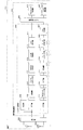
- FIG. 1 An example of the reconnection processing sequence of the relay station 400 is shown in FIG.
- step S62 when the relay station 400 detects RLF in the relay link (step S62), it starts reconnection processing with the base station 300 (step S63).
- step S60 when the base station 300 detects that communication with the relay station 400 is interrupted (step S60), the base station 300 sets an allowable time for reconnection processing from the relay station 400 (step S61). Wait for reconnection request. At this time, the allowable time for the reconnection process is set in consideration of the service type (QoS) used by the terminal 200 under the relay station 400.
- QoS service type
- step S71 the relay station 400 determines whether a new cell has been detected.
- step S71 the relay station 400 determines that a new cell has not been detected.
- step S79 the reconnection process fails.
- step S72 a reconnection request message (RRC Connection Re-establishment Request) is transmitted to the base station 300 (step S72).
- the base station 300 determines whether or not a reconnection request message has been received from the relay station 400 (step S73). If it has been received (YES route in step S73), the reconnection instruction message (RRC Connection Re-establishment) Is transmitted to the relay station 400 (step S74). On the other hand, when it is determined that the reconnection request message has not been received from the relay station 400 (NO route in step S73), the reconnection process fails (step S79).
- the relay station 400 determines whether or not a reconnection instruction message has been received from the base station 300 (step S75). If it has been received (YES route in step S75), the reconnection completion message (RRC Connection Re-establishment Complete) ) To the base station 300 (step S76). On the other hand, when it is determined that the reconnection instruction message has not been received from the base station 300 (NO route in step S75), the reconnection process fails (step S79).
- the base station 300 determines whether or not a reconnection completion message has been received from the relay station 400 (step S77). If it has been received (YES route in step S77), the reconnection process is successful (step S78). If the reconnection is successful, the relay station 400 and the terminal 200 under the relay station 400 can maintain communication. On the other hand, when it is determined that the reconnection completion message has not been received from the relay station 400 (NO route in step S77), the reconnection process fails (step S79).
- the base station 300 and the relay station 400 determine whether or not the reconnection process is successful (steps S64 and S65). If it is determined that the reconnection process has succeeded (YES route in steps S64 and S65), the above procedure ends (steps S69 and S70). On the other hand, if it is determined that the reconnection process has failed (NO route in step S65), the relay station 400 determines whether all the state recovery monitoring timers have expired (step S67). If the operating state recovery management timer remains (NO route in step S67), the above reconnection process is repeatedly executed, and if it is determined that all the state recovery monitoring timers have expired (YES in step S67). Route), the relay station 400 ends the above procedure (step S70).
- the base station 300 determines whether the allowable time for the reconnection process has expired (step S66). Here, if it is determined that the allowable time for the reconnection process has not expired (NO route in step S66), the base station 300 waits for a reconnection request message from the relay station 400.
- step S66 determines that the allowable time for the reconnection process has expired (YES route in step S66)
- the base station 300 determines that the reconnection has failed and the connection with the network is lost, and the relay station 400 and The network management information of the terminal 200 under the relay station 400 is cleared, the terminal management information managed by the base station 300 is updated (step S68), and the above procedure is terminated (step S69).
- the base station 300 can not allow the reconnection process from the relay station 400, so that the processing load in the base station 300 is reduced and efficient. System operation can be realized.
- the configurations and functions of the base station 300, the terminal 200, and the relay station 400 in the above-described embodiment may be selected as necessary, or may be used in appropriate combination. . In other words, the above-described configurations and functions may be selected or used in appropriate combination so that the functions of the present invention can be exhibited.
- each timeout value of the state recovery monitoring timer is determined based on the priority of the service being used by the terminal 200.
- the priority of the service for example, service quality (QoS), service There are types.
- the priority of the service may be determined based on, for example, the header content or the data content included in the packet data.
Abstract
A wireless communication system comprising a base station, a terminal, and a relay station (400) for relaying a wireless signal transmitted and received between the base station and the terminal, wherein the relay station is provided with: a first processor (421) for executing processing for reconnection with the base station with respect to calls corresponding to each of a plurality of intervals that are based on a certain timing, said processing being executed each time one of the plurality of intervals elapses; a transmitter (402) for transmitting, to the terminal, a message for notifying disconnection of a corresponding call due to the elapse of a specified time period when reconnection to the base station is not possible before the elapse of the specified time period from the start of the reconnection processing for the calls corresponding to each interval, and the terminal is provided with: a receiver for receiving the message transmitted from the relay station; and a second processor for executing the call disconnection processing for the corresponding call in response to receiving the message.
Description
本発明は、無線通信システム、リレー局、端末及び無線通信方法に関する。前記無線通信システムは、例えば、基地局と端末との間で送受信される無線信号を中継するリレー局を含む。
The present invention relates to a wireless communication system, a relay station, a terminal, and a wireless communication method. The radio communication system includes, for example, a relay station that relays radio signals transmitted and received between a base station and a terminal.
近年の無線通信分野では、音声通話だけでなく、インターネットへのアクセス、ストリーミング放送の配信、音楽や映像のようなコンテンツの配信など、様々なサービスが展開されている。また、通信速度の高速化や、接続エリアの拡張化などにより、これらのサービスをどこでも高品質に提供することが求められている。
通信速度を高速化すべく、標準化団体である3rd Generation Partnership Project(3GPP)では、Long Term Evolution(LTE)が仕様化され、サービスが開始されている。このLTE方式では、最大で、下り約300Mbps、上り約150Mbpsの通信が可能である。 In the wireless communication field in recent years, various services such as access to the Internet, distribution of streaming broadcasts, distribution of contents such as music and video as well as voice calls have been developed. In addition, it is required to provide these services with high quality everywhere by increasing the communication speed and expanding the connection area.
In order to increase the communication speed, the 3rd Generation Partnership Project (3GPP), which is a standardization organization, specifies Long Term Evolution (LTE) and starts a service. In this LTE system, communication of about 300 Mbps for downlink and about 150 Mbps for uplink is possible at maximum.
また、接続エリアを拡張化すべく、LTEの次世代規格であるLTE-Advanced(LTE-A)では、端末と基地局との間で送受信される無線信号を中継するリレー局の導入が検討されている。
なお、LTE方式の通信システムにおいて、移動局がRadio Resource Control(RRC)コネクションにおけるリンク障害(RLF:Radio Link Failure)を検出した場合の基地局への再接続要求の正当性を保証する方法が提案されている(下記特許文献1)。 In order to expand the connection area, LTE-Advanced (LTE-A), the next generation standard of LTE, is considering the introduction of a relay station that relays radio signals transmitted and received between the terminal and the base station. Yes.
In the LTE communication system, a method for guaranteeing the validity of a reconnection request to a base station when a mobile station detects a link failure (RLF) in a Radio Resource Control (RRC) connection is proposed. (Patent Document 1 below).
なお、LTE方式の通信システムにおいて、移動局がRadio Resource Control(RRC)コネクションにおけるリンク障害(RLF:Radio Link Failure)を検出した場合の基地局への再接続要求の正当性を保証する方法が提案されている(下記特許文献1)。 In order to expand the connection area, LTE-Advanced (LTE-A), the next generation standard of LTE, is considering the introduction of a relay station that relays radio signals transmitted and received between the terminal and the base station. Yes.
In the LTE communication system, a method for guaranteeing the validity of a reconnection request to a base station when a mobile station detects a link failure (RLF) in a Radio Resource Control (RRC) connection is proposed. (
例えば、端末の移動などにより端末周辺の無線伝播環境が変化すると、端末での受信品質が劣化する場合がある。受信品質が劣化すると、基地局との接続状態が不安定になることがあるため、端末は、無線信号の受信品質に基づいて、基地局との接続状態を監視する。
無線通信の維持に支障をきたすレベルまで受信品質が劣化し、且つ、一定時間内に受信品質の状態が復旧しない場合、端末は、RLFの発生を検出し、他の基地局や、他のセルあるいは他のセクタなどへ接続先を切り替える再接続処理を実施する。 For example, when the radio propagation environment around the terminal changes due to movement of the terminal, the reception quality at the terminal may deteriorate. When the reception quality deteriorates, the connection state with the base station may become unstable. Therefore, the terminal monitors the connection state with the base station based on the reception quality of the radio signal.
When the reception quality deteriorates to a level that hinders the maintenance of wireless communication and the state of the reception quality is not restored within a certain time, the terminal detects the occurrence of RLF, and detects other base stations or other cells. Alternatively, reconnection processing for switching the connection destination to another sector or the like is performed.
ここで、端末の再接続処理の一例を図1に示す。
この図1に示すように、端末は、所定の接続シーケンスにより基地局と接続を確立し、通信を開始すると(ステップS1)、端末と基地局との間のリンク(アクセスリンク)において、無線信号の受信品質の測定を定期あるいは不定期に行なう(ステップS2)。
そして、端末は、測定した受信品質と所定の閾値レベルとを比較し、受信品質が所定の閾値レベルよりも小さい場合にリンク異常を検出する(ステップS3)。 Here, an example of the terminal reconnection process is shown in FIG.
As shown in FIG. 1, when a terminal establishes a connection with a base station by a predetermined connection sequence and starts communication (step S1), a radio signal is transmitted on a link (access link) between the terminal and the base station. The reception quality is measured regularly or irregularly (step S2).
Then, the terminal compares the measured reception quality with a predetermined threshold level, and detects a link abnormality when the reception quality is lower than the predetermined threshold level (step S3).
ここで、リンク異常が検出されない場合(ステップS3のNOルート)、端末は、ステップS2及びS3の処理を繰り返す。一方、リンク異常を検出した場合(ステップS3のYESルート)、端末は、一定時間内にリンク異常状態が復旧しないかどうかの監視を行なうため、タイマ(状態復旧監視タイマ)を起動する(ステップS4)。
次いで、端末は、アクセスリンクのリンク異常状態が復旧したかどうかを監視する(ステップS5)。例えば、端末は、測定した受信品質と所定の閾値レベルとを比較し、受信品質が所定の閾値レベル以上であるかどうかを監視する。 If no link abnormality is detected (NO route in step S3), the terminal repeats the processes in steps S2 and S3. On the other hand, when a link abnormality is detected (YES route in step S3), the terminal starts a timer (state restoration monitoring timer) in order to monitor whether or not the link abnormality state is recovered within a certain time (step S4). ).
Next, the terminal monitors whether the link abnormal state of the access link has been recovered (step S5). For example, the terminal compares the measured reception quality with a predetermined threshold level and monitors whether the reception quality is equal to or higher than the predetermined threshold level.
そして、端末は、アクセスリンクの状態が復旧したかどうかを判定する(ステップS6)。ここで、アクセスリンクの状態が復旧した場合(ステップS6のYESルート)、状態復旧監視タイマを停止し(ステップS7)、処理をステップS2へ移行する。一方、アクセスリンクの状態が復旧しない場合(ステップS6のNOルート)、端末は、状態復旧監視タイマがタイムアウトしたかどうかを判定する(ステップS8)。
Then, the terminal determines whether or not the access link state has been restored (step S6). Here, when the state of the access link is restored (YES route in step S6), the state restoration monitoring timer is stopped (step S7), and the process proceeds to step S2. On the other hand, when the state of the access link is not recovered (NO route in step S6), the terminal determines whether the state recovery monitoring timer has timed out (step S8).
状態復旧監視タイマがタイムアウトしていない場合(ステップS8のNOルート)、端末は、ステップS5,S6及びS8の処理を繰り返す。一方、状態復旧監視タイマがタイムアウトした場合(ステップS8のYESルート)、端末は、RLFの発生を検出し、他の基地局や、他のセルあるいは他のセクタなどへ接続先を切り替える再接続処理を実施する(ステップS9)。
When the state recovery monitoring timer has not timed out (NO route of step S8), the terminal repeats the processes of steps S5, S6 and S8. On the other hand, when the state recovery monitoring timer times out (YES route in step S8), the terminal detects the occurrence of RLF and switches the connection destination to another base station, another cell, another sector, or the like. (Step S9).
そして、端末は、再接続処理が成功したかどうかを判定し(ステップS10)、再接続処理が成功したと判定した場合は(ステップS10のYESルート)、処理をステップS2へ移行し、通常状態へ移行する。一方、再接続処理が失敗したと判定した場合は(ステップS10のNOルート)、呼切断処理を行ない、基地局との通信を終了する(ステップS11)。なお、通信を終了した端末は、例えば、基地局との接続シーケンスの実行を待つ待ち受け状態へ移行する。
Then, the terminal determines whether or not the reconnection process is successful (step S10). If it is determined that the reconnection process is successful (YES route of step S10), the process proceeds to step S2, and the normal state Migrate to On the other hand, if it is determined that the reconnection process has failed (NO route in step S10), the call disconnection process is performed, and the communication with the base station is terminated (step S11). Note that the terminal that has completed communication shifts to a standby state in which, for example, the connection sequence with the base station is awaited.
ここで、状態復旧監視タイマのタイムアウト値(以下、単にタイマ値ともいう)は、端末が利用するサービスのサービス品質(QoS:Quality of Service)に基づいて決定される。
例えば、端末が音声通信サービスを利用している場合、タイマ値が大きい(長い)ほどRLF検出までの時間が大きくなり、その間、無音や異音などが発生し、ユーザに不快感を与えることになるため、この場合、タイマ値は小さく(短く)設定される。 Here, the timeout value of the state recovery monitoring timer (hereinafter also simply referred to as a timer value) is determined based on the quality of service (QoS) of the service used by the terminal.
For example, when the terminal uses a voice communication service, the time until the RLF is detected increases as the timer value increases (longer), and during that time, silence, abnormal noise, etc. occur, giving the user an unpleasant feeling. Therefore, in this case, the timer value is set to be small (short).
一方、端末がウェブブラウジングなどのようにリアルタイム通信でないパケット通信呼などの通信サービスを利用している場合、時間がかかっても通信ができればよいので、タイマ値は音声通信サービスを利用している場合に比して大きめ(長め)に設定される。
Universal Mobile Telecommunications System(UMTS)におけるタイマ値の一例として、3GPP TS25.331では、音声呼などの回線交換呼のタイマ値としてT314、パケット交換呼のタイマ値としてT315が規定されている。なお、T314の初期値は12秒、T315の初期値は180秒として規定されている。 On the other hand, if the terminal is using a communication service such as a packet communication call that is not real-time communication, such as web browsing, it is only necessary to be able to communicate even if it takes time, so if the timer value uses a voice communication service It is set larger (longer) than.
As an example of a timer value in the Universal Mobile Telecommunications System (UMTS), 3GPP TS25.331 defines T314 as a timer value for a circuit-switched call such as a voice call and T315 as a timer value for a packet-switched call. The initial value of T314 is defined as 12 seconds, and the initial value of T315 is defined as 180 seconds.
しかしながら、前述の特許文献1などには、LTE-A方式の通信システムに用いられるリレー局において、基地局とリレー局との間のリンク(リレーリンク)のRLF検出処理や再接続処理をどのように行なうかについての具体的な提案はなく、無線通信システムにおける効率的な無線通信方法を提供することができない。
そこで、本発明は、無線通信システムにおいて効率的に無線通信を行なって、端末でのサービス品質を維持することを目的の1つとする。 However, in the above-describedPatent Document 1 and the like, how to perform RLF detection processing and reconnection processing of a link (relay link) between a base station and a relay station in a relay station used in an LTE-A communication system. There is no specific proposal about whether to perform the wireless communication, and an efficient wireless communication method in the wireless communication system cannot be provided.
Accordingly, an object of the present invention is to efficiently perform wireless communication in a wireless communication system and maintain service quality at a terminal.
そこで、本発明は、無線通信システムにおいて効率的に無線通信を行なって、端末でのサービス品質を維持することを目的の1つとする。 However, in the above-described
Accordingly, an object of the present invention is to efficiently perform wireless communication in a wireless communication system and maintain service quality at a terminal.
なお、前記目的に限らず、後述する発明を実施するための形態に示す各構成により導かれる作用効果であって、従来の技術によっては得られない作用効果を奏することも本発明の他の目的の一つとして位置付けることができる。
In addition, the present invention is not limited to the above-described object, and other effects of the present invention can be achieved by the functions and effects derived from the respective configurations shown in the embodiments for carrying out the invention which will be described later. It can be positioned as one of
(1)第1の案として、基地局と、端末と、該基地局と該端末との間で送受信される無線信号を中継するリレー局とを含む無線通信システムにおいて、該リレー局は、あるタイミングを基準とした複数の期間の経過毎に、それぞれの期間に対応する呼について、該基地局との間の再接続処理を実行する第1の処理装置と、前記それぞれの期間に対応する呼についての前記再接続処理の開始から所定時間の経過前に該基地局と再接続できない場合、該所定時間の経過により、対応する呼の呼切断を通知するメッセージを該端末に送信する送信部とをそなえ、該端末は、該リレー局から送信された前記メッセージを受信する受信部と、前記メッセージの受信に応じて、対応する呼の呼切断処理を実行する第2の処理装置とをそなえた、無線通信システムを用いることができる。
(1) As a first proposal, in a wireless communication system including a base station, a terminal, and a relay station that relays a radio signal transmitted and received between the base station and the terminal, the relay station is A first processing device that executes reconnection processing with the base station for a call corresponding to each period for each elapse of a plurality of periods based on timing, and a call corresponding to each period A transmitter that transmits a message notifying call disconnection of the corresponding call to the terminal when the predetermined time elapses when reconnection to the base station cannot be performed before the elapse of a predetermined time from the start of the reconnection processing for The terminal includes a receiving unit that receives the message transmitted from the relay station, and a second processing device that executes call disconnection processing for a corresponding call in response to reception of the message. ,Wireless communication The stem can be used.
(2)また、第2の案として、基地局と端末との間で送受信される無線信号を中継するリレー局において、あるタイミングを基準とした複数の期間の経過毎に、それぞれの期間に対応する呼について、該基地局との間の再接続処理を実行する処理装置と、前記それぞれの期間に対応する呼についての前記再接続処理の開始から所定時間の経過前に該基地局と再接続できない場合、該所定時間の経過により、対応する呼の呼切断を通知するメッセージを該端末に送信する送信部とをそなえた、リレー局を用いることができる。
(2) As a second plan, in a relay station that relays radio signals transmitted and received between the base station and the terminal, each period is handled for each of a plurality of periods based on a certain timing. A processing device for executing reconnection processing with the base station for a call to be performed, and reconnection with the base station before a predetermined time elapses from the start of the reconnection processing for the call corresponding to each period If this is not possible, it is possible to use a relay station that includes a transmitter that transmits a message notifying the disconnection of the corresponding call to the terminal as the predetermined time elapses.
(3)さらに、第3の案として、リレー局を介して基地局との間で無線信号を送受信する端末において、あるタイミングを基準とした複数の期間の経過毎に、それぞれの期間に対応する呼について該リレー局で実行される再接続処理の開始から所定時間の経過前に該リレー局が該基地局と再接続できない場合、該所定時間の経過により該リレー局から送信される、呼切断を通知するメッセージを受信する受信部と、前記メッセージの受信に応じて、対応する呼の呼切断処理を実行する処理装置とをそなえた、端末を用いることができる。
(3) Further, as a third plan, in a terminal that transmits and receives a radio signal to and from a base station via a relay station, each period corresponds to each of a plurality of periods with a certain timing as a reference. If the relay station cannot reconnect to the base station before the elapse of a predetermined time from the start of reconnection processing executed at the relay station for the call, the call disconnection is transmitted from the relay station after the elapse of the predetermined time. It is possible to use a terminal that includes a receiving unit that receives a message for notifying a message and a processing device that executes a call disconnection process for a corresponding call in response to the reception of the message.
(4)また、第4の案として、基地局と、端末と、該基地局と該端末との間で送受信される無線信号を中継するリレー局とを含む無線通信システムに用いられる無線通信方法において、該リレー局は、あるタイミングを基準とした複数の期間の経過毎に、それぞれの期間に対応する呼について、該基地局との間の再接続処理を実行し、前記それぞれの期間に対応する呼についての前記再接続処理の開始から所定時間の経過前に該基地局と再接続できない場合、該所定時間の経過により、対応する呼の呼切断を通知するメッセージを該端末に送信し、該端末は、該リレー局から送信された前記メッセージを受信し、前記メッセージの受信に応じて、対応する呼の呼切断処理を実行する、無線通信方法を用いることができる。
(4) As a fourth proposal, a radio communication method used in a radio communication system including a base station, a terminal, and a relay station that relays radio signals transmitted and received between the base station and the terminal The relay station performs reconnection processing with the base station for a call corresponding to each period every time a plurality of periods with a certain timing as a reference, and corresponds to each period. If the base station cannot be reconnected before the elapse of a predetermined time from the start of the reconnection process for the call to be made, a message notifying the call disconnection of the corresponding call is transmitted to the terminal by the elapse of the predetermined time, The terminal can use a wireless communication method that receives the message transmitted from the relay station and executes a call disconnection process for a corresponding call in response to reception of the message.
無線通信システムにおいて効率的に無線通信を行なって、端末でのサービス品質を維持することが可能となる。
It is possible to efficiently perform wireless communication in a wireless communication system and maintain service quality at the terminal.
以下、図面を参照して本発明の実施の形態を説明する。ただし、以下に示す実施の形態は、あくまでも例示に過ぎず、以下に示す実施形態で明示しない種々の変形や技術の適用を排除する意図はない。即ち、実施形態及び各変形例を、本発明の趣旨を逸脱しない範囲で種々変形して実施できることはいうまでもない。
〔1〕一実施形態の説明
(1.1)無線通信システム
図2は一実施形態に係る無線通信システムの構成の一例を示す図である。 Embodiments of the present invention will be described below with reference to the drawings. However, the embodiment described below is merely an example, and there is no intention to exclude various modifications and technical applications that are not explicitly described in the embodiment described below. That is, it goes without saying that the embodiment and each modified example can be variously modified without departing from the spirit of the present invention.
[1] Description of Embodiment (1.1) Radio Communication System FIG. 2 is a diagram illustrating an example of a configuration of a radio communication system according to an embodiment.
この図2に示す無線通信システム100は、例示的に、端末(UE:User Equipment)200-1,200-2と、基地局300と、リレー局400とをそなえる。なお、以下では、端末200-1,200-2を区別しない場合、単に端末200と表記する。また、例えば、端末200はユーザによって移動可能で、その意味で、無線移動端末あるいは移動局(MS:Mobile Station)と同義である。さらに、端末200,基地局300,リレー局400の数は、図2に例示する数にそれぞれ限定されない。また、以下では、基地局300とリレー局400との間の接続をリレーリンクと称し、基地局300と端末200との間の接続及びリレー局400と端末200との間の接続をアクセスリンクと称する。
2 includes, for example, terminals (UE: User 端末 Equipment) 200-1 and 200-2, a base station 300, and a relay station 400. Hereinafter, when the terminals 200-1 and 200-2 are not distinguished, they are simply referred to as the terminal 200. Further, for example, the terminal 200 can be moved by a user, and in this sense, is synonymous with a wireless mobile terminal or a mobile station (MS: Mobile (Station). Further, the numbers of terminals 200, base stations 300, and relay stations 400 are not limited to the numbers illustrated in FIG. Hereinafter, the connection between the base station 300 and the relay station 400 is referred to as a relay link, and the connection between the base station 300 and the terminal 200 and the connection between the relay station 400 and the terminal 200 are referred to as access links. Called.
ここで、基地局300は、セルやセクタなどで構成される通信サービスエリア500を提供し、当該通信サービスエリア500内に位置する端末200やリレー局400と無線通信することができる。
例えば、基地局300は、自局300が提供する通信サービスエリア500内に位置する端末200-1とアクセスリンクを介して直接的に無線通信することができる。また、基地局300は、自局300が提供する通信サービスエリア500内に位置するリレー局400ともリレーリンクを介して直接的に無線通信することができる。 Here, thebase station 300 provides a communication service area 500 composed of cells, sectors, and the like, and can wirelessly communicate with the terminal 200 and the relay station 400 located in the communication service area 500.
For example, thebase station 300 can directly wirelessly communicate with the terminal 200-1 located in the communication service area 500 provided by the own station 300 via the access link. In addition, the base station 300 can directly wirelessly communicate with the relay station 400 located in the communication service area 500 provided by the own station 300 via the relay link.
例えば、基地局300は、自局300が提供する通信サービスエリア500内に位置する端末200-1とアクセスリンクを介して直接的に無線通信することができる。また、基地局300は、自局300が提供する通信サービスエリア500内に位置するリレー局400ともリレーリンクを介して直接的に無線通信することができる。 Here, the
For example, the
一方、基地局300は、図2に示す状態では、端末200-2とは直接的に無線通信することができない。端末200-2は、基地局300が提供する通信サービスエリア500内に位置していないからである。
また、リレー局400は、基地局300と端末200-2との間で送受信される無線信号を中継する。図2に示す例では、リレー局400は、通信サービスエリアを拡大するような位置に配置されている。なお、リレー局400は、所定の位置に固定的に配置されてもよいし、移動可能であってもよい。リレー局400が移動局として構成される場合、リレー局400が提供する通信サービスエリア600も移動することになる。 On the other hand,base station 300 cannot directly wirelessly communicate with terminal 200-2 in the state shown in FIG. This is because the terminal 200-2 is not located in the communication service area 500 provided by the base station 300.
Therelay station 400 relays a radio signal transmitted / received between the base station 300 and the terminal 200-2. In the example shown in FIG. 2, the relay station 400 is arranged at a position that expands the communication service area. Note that the relay station 400 may be fixedly disposed at a predetermined position or may be movable. When the relay station 400 is configured as a mobile station, the communication service area 600 provided by the relay station 400 also moves.
また、リレー局400は、基地局300と端末200-2との間で送受信される無線信号を中継する。図2に示す例では、リレー局400は、通信サービスエリアを拡大するような位置に配置されている。なお、リレー局400は、所定の位置に固定的に配置されてもよいし、移動可能であってもよい。リレー局400が移動局として構成される場合、リレー局400が提供する通信サービスエリア600も移動することになる。 On the other hand,
The
例えば、リレー局400は、基地局300から受信した無線信号を、自局400が提供する通信サービスエリア600内に位置する端末200-2へアクセスリンクを介して中継送信することができる。さらに、リレー局400は、自局400が提供する通信サービスエリア600内に位置する端末200-2から受信した無線信号を、リレーリンクを介して基地局300へ中継送信することができる。
For example, the relay station 400 can relay and transmit the radio signal received from the base station 300 to the terminal 200-2 located in the communication service area 600 provided by the own station 400 via the access link. Furthermore, the relay station 400 can relay and transmit the radio signal received from the terminal 200-2 located in the communication service area 600 provided by the own station 400 to the base station 300 via the relay link.
そして、端末200-1は、自局200-1が属する通信サービスエリア500を提供する基地局300とアクセスリンクを介して直接的に無線通信することができる。また、端末200-2は、自局200-2が属する通信サービスエリア600を提供するリレー局400を介して、間接的に、基地局300と無線通信することができる。
以下、端末200,基地局300及びリレー局400の構成の一例について説明する。なお、端末200,基地局300及びリレー局400の各構成については、LTEの仕様に倣って説明するが、あくまで一例であり、本発明は以下に示すような構成に限定されないのはいうまでもない。 Then, the terminal 200-1 can directly perform wireless communication with thebase station 300 that provides the communication service area 500 to which the terminal 200-1 belongs via an access link. The terminal 200-2 can wirelessly communicate with the base station 300 indirectly via the relay station 400 that provides the communication service area 600 to which the terminal 200-2 belongs.
Hereinafter, an example of the configuration of the terminal 200, thebase station 300, and the relay station 400 will be described. In addition, although each structure of the terminal 200, the base station 300, and the relay station 400 is demonstrated according to the specification of LTE, it is an example to the last, and it cannot be overemphasized that this invention is not limited to a structure as shown below. Absent.
以下、端末200,基地局300及びリレー局400の構成の一例について説明する。なお、端末200,基地局300及びリレー局400の各構成については、LTEの仕様に倣って説明するが、あくまで一例であり、本発明は以下に示すような構成に限定されないのはいうまでもない。 Then, the terminal 200-1 can directly perform wireless communication with the
Hereinafter, an example of the configuration of the terminal 200, the
(1.2)端末200
図3は一実施形態に係る端末200の構成の一例を示す図である。
この図3に示す端末200は、例示的に、受信アンテナ201と、送信アンテナ202と、無線部203と、端末側処理部222とをそなえる。
受信アンテナ201は、無線信号を受信する。受信アンテナ201で受信される無線信号には、例えば、基地局300またはリレー局400から送信された無線信号が含まれる。 (1.2)Terminal 200
FIG. 3 is a diagram illustrating an example of a configuration of the terminal 200 according to an embodiment.
3 includes, for example, areception antenna 201, a transmission antenna 202, a radio unit 203, and a terminal-side processing unit 222.
The receivingantenna 201 receives a radio signal. The radio signal received by the receiving antenna 201 includes, for example, a radio signal transmitted from the base station 300 or the relay station 400.
図3は一実施形態に係る端末200の構成の一例を示す図である。
この図3に示す端末200は、例示的に、受信アンテナ201と、送信アンテナ202と、無線部203と、端末側処理部222とをそなえる。
受信アンテナ201は、無線信号を受信する。受信アンテナ201で受信される無線信号には、例えば、基地局300またはリレー局400から送信された無線信号が含まれる。 (1.2)
FIG. 3 is a diagram illustrating an example of a configuration of the terminal 200 according to an embodiment.
3 includes, for example, a
The receiving
即ち、受信アンテナ201は、後述するように、あるタイミングを基準とした複数の期間の経過毎に、それぞれの期間に対応する呼についてリレー局400で実行される再接続処理の開始から所定時間の経過前にリレー局400が基地局300と再接続できない場合、前記所定時間の経過によりリレー局400から送信される、呼切断を通知するメッセージを受信する受信部の一例として機能し得る。
That is, as will be described later, the receiving antenna 201 receives a predetermined time from the start of the reconnection process executed by the relay station 400 for a call corresponding to each period every time a plurality of periods with a certain timing as a reference. When the relay station 400 cannot reconnect to the base station 300 before the elapse of time, the relay station 400 can function as an example of a receiving unit that receives a message for notifying a call disconnection transmitted from the relay station 400 when the predetermined time elapses.
また、送信アンテナ202は、無線信号を送信する。送信アンテナ202で送信された無線信号は、例えば、基地局300またはリレー局400で受信される。
なお、受信アンテナ201及び送信アンテナ202は、アンテナ共用器などにより共用化されてもよい。
無線部203は、受信アンテナ201で受信した高周波信号をベースバンド信号へ変換する一方、生成したベースバンド信号を高周波信号へ変換して送信アンテナ202を介して送信する。 The transmission antenna 202 transmits a radio signal. The radio signal transmitted by the transmission antenna 202 is received by thebase station 300 or the relay station 400, for example.
Note that thereception antenna 201 and the transmission antenna 202 may be shared by an antenna duplexer or the like.
Theradio unit 203 converts the high-frequency signal received by the receiving antenna 201 into a baseband signal, converts the generated baseband signal into a high-frequency signal, and transmits the high-frequency signal via the transmission antenna 202.
なお、受信アンテナ201及び送信アンテナ202は、アンテナ共用器などにより共用化されてもよい。
無線部203は、受信アンテナ201で受信した高周波信号をベースバンド信号へ変換する一方、生成したベースバンド信号を高周波信号へ変換して送信アンテナ202を介して送信する。 The transmission antenna 202 transmits a radio signal. The radio signal transmitted by the transmission antenna 202 is received by the
Note that the
The
端末側処理部222は、端末200における各種の処理を実行する。例えば、端末側処理部222は、リレー局400からの呼切断を通知するメッセージに応じて、対応する呼の呼切断処理を実行する第2の処理装置の一例として機能し得る。
このため、端末側処理部222は、例示的に、レイヤ1処理部204と、レイヤ2処理部205と、RRCレイヤ処理部206と、アプリケーションレイヤ処理部207とをそなえる。 The terminalside processing unit 222 executes various processes in the terminal 200. For example, the terminal-side processing unit 222 can function as an example of a second processing device that executes call disconnection processing for a corresponding call in response to a message that notifies call disconnection from the relay station 400.
For this reason, the terminalside processing unit 222 illustratively includes a layer 1 processing unit 204, a layer 2 processing unit 205, an RRC layer processing unit 206, and an application layer processing unit 207.
このため、端末側処理部222は、例示的に、レイヤ1処理部204と、レイヤ2処理部205と、RRCレイヤ処理部206と、アプリケーションレイヤ処理部207とをそなえる。 The terminal
For this reason, the terminal
レイヤ1処理部204は、受信信号及び送信信号について、レイヤ1での所定のデータ処理を行なう。このため、レイヤ1処理部204は、例示的に、測定部208と、Fast Fourier Transform(FFT)部209と、復調部210と、デレートマッチング部211と、Hybrid Automatic Repeat reQuest(HARQ)合成部212とをそなえる。また、レイヤ1処理部204は、例示的に、ターボ復号部213と、Cyclic Redundancy Check(CRC)処理部214とをそなえるとともに、Inverse FFT(IFFT)部215と、サブキャリアマッピング部216とをそなえる。さらに、レイヤ1処理部204は、例示的に、Discrete Fourier Transform(DFT)部217と、変調部218と、レートマッチング部219と、ターボ符号化部220と、CRC付与部221とをそなえる。
The layer 1 processing unit 204 performs predetermined data processing in the layer 1 on the reception signal and the transmission signal. For this reason, the layer 1 processing unit 204 exemplarily includes a measurement unit 208, a Fast-Fourier-Transform (FFT) unit 209, a demodulation unit 210, a derate matching unit 211, and a Hybrid-automatic Repeat-reQuest (HARQ) synthesis unit. 212. The layer 1 processing unit 204 includes, for example, a turbo decoding unit 213 and a Cyclic Redundancy Check (CRC) processing unit 214, and an Inverse / FFT (IFFT) unit 215 and a subcarrier mapping unit 216. . Further, the layer 1 processing unit 204 includes, for example, a Discrete-Fourier-Transform (DFT) unit 217, a modulation unit 218, a rate matching unit 219, a turbo encoding unit 220, and a CRC adding unit 221.
ここで、FFT部209は、無線部から入力される受信信号について高速フーリエ変換処理を施し、Orthogonal Frequency Division Multiple Access(OFDMA)シンボルを復調する。FFT部209によって復調されたOFDMAシンボルは、復調部210へ出力される。
また、測定部208は、受信信号の受信品質レベルの測定を行なう。例えば、測定部208は、受信信号の受信品質レベルと所定のレベル閾値とを比較判定することにより、アクセスリンクでのリンク異常を検出することができる。また、測定部208は、例えば、セルサーチ機能を具備してもよい。 Here,FFT section 209 performs fast Fourier transform processing on the received signal input from the radio section, and demodulates an Orthogonal Frequency Division Multiple Access (OFDMA) symbol. The OFDMA symbol demodulated by the FFT unit 209 is output to the demodulation unit 210.
Measurement unit 208 measures the reception quality level of the received signal. For example, the measurement unit 208 can detect a link abnormality in the access link by comparing and determining the reception quality level of the received signal and a predetermined level threshold value. In addition, the measurement unit 208 may have a cell search function, for example.
また、測定部208は、受信信号の受信品質レベルの測定を行なう。例えば、測定部208は、受信信号の受信品質レベルと所定のレベル閾値とを比較判定することにより、アクセスリンクでのリンク異常を検出することができる。また、測定部208は、例えば、セルサーチ機能を具備してもよい。 Here,
さらに、復調部210は、FFT部209から入力される、多値変調済みのシンボルを復調する。なお、多値変調には、例えば、Quadrature Phase Shift Keying(QPSK),16Quadrature Amplitude Modulation(16QAM)及び64QAMなどがある。復調部210によって復調された信号はデレートマッチング部211へ出力される。
即ち、上記測定部208,FFT部209及び復調部210は、例えば、直行周波数分割多重アクセス(OFDMA)方式による復調処理を行なう復調ブロックの一例として機能する。 Further, thedemodulator 210 demodulates the multi-level modulated symbol input from the FFT unit 209. Note that multilevel modulation includes, for example, Quadrature Phase Shift Keying (QPSK), 16 Quadrature Amplitude Modulation (16QAM), and 64QAM. The signal demodulated by the demodulation unit 210 is output to the derate matching unit 211.
That is, themeasurement unit 208, the FFT unit 209, and the demodulation unit 210 function as an example of a demodulation block that performs demodulation processing by an orthogonal frequency division multiple access (OFDMA) scheme, for example.
即ち、上記測定部208,FFT部209及び復調部210は、例えば、直行周波数分割多重アクセス(OFDMA)方式による復調処理を行なう復調ブロックの一例として機能する。 Further, the
That is, the
また、デレートマッチング部211は、復調部210から入力された信号について、割り当てられた物理チャネルリソースに応じて伸張あるいは縮小されているデータを元に戻す処理を施す。
HARQ合成部212は、デレートマッチング部211から入力された信号について、HARQ再送処理を行なうことにより、再送データの合成を行なう。 Further, thederate matching unit 211 performs a process for restoring the data that has been expanded or contracted according to the allocated physical channel resource, on the signal input from the demodulation unit 210.
TheHARQ combining unit 212 combines retransmission data by performing HARQ retransmission processing on the signal input from the derate matching unit 211.
HARQ合成部212は、デレートマッチング部211から入力された信号について、HARQ再送処理を行なうことにより、再送データの合成を行なう。 Further, the
The
ターボ復号部213は、HARQ合成部212から出力されるターボ符号化されたデータについて、ターボ復号処理を施すことにより、データを復号する。
CRC処理部214は、CRC処理を行なうことにより、ターボ復号部213によって復号されたデータに誤りが含まれているかどうかを判定する。
即ち、上記デレートマッチング部211,HARQ合成部212,ターボ復号部213及びCRC処理部214は、例えば、受信信号の復号処理を行なう復号ブロックの一例として機能する。 Theturbo decoding unit 213 decodes the data by performing turbo decoding processing on the turbo encoded data output from the HARQ combining unit 212.
TheCRC processing unit 214 performs CRC processing to determine whether or not the data decoded by the turbo decoding unit 213 includes an error.
That is, thederate matching unit 211, the HARQ synthesis unit 212, the turbo decoding unit 213, and the CRC processing unit 214 function as an example of a decoding block that performs a decoding process on a received signal, for example.
CRC処理部214は、CRC処理を行なうことにより、ターボ復号部213によって復号されたデータに誤りが含まれているかどうかを判定する。
即ち、上記デレートマッチング部211,HARQ合成部212,ターボ復号部213及びCRC処理部214は、例えば、受信信号の復号処理を行なう復号ブロックの一例として機能する。 The
The
That is, the
また、CRC付与部221は、送信データからCRCコードを算出するとともに、送信データに算出したCRCコードを付与して、ターボ符号化部220へ出力する。
ターボ符号化部220は、CRC付与部221から入力されたデータについて、ターボ符号化処理を施す。
レートマッチング部219は、ターボ符号化部220から入力された信号について、割り当てられた物理チャネルリソースに応じてデータの伸張あるいは縮小する処理を施す。CRC adding section 221 calculates a CRC code from the transmission data, adds the calculated CRC code to the transmission data, and outputs the CRC code to turbo coding section 220.
Theturbo encoding unit 220 performs turbo encoding processing on the data input from the CRC adding unit 221.
Therate matching unit 219 performs a process of expanding or reducing data on the signal input from the turbo encoding unit 220 according to the allocated physical channel resource.
ターボ符号化部220は、CRC付与部221から入力されたデータについて、ターボ符号化処理を施す。
レートマッチング部219は、ターボ符号化部220から入力された信号について、割り当てられた物理チャネルリソースに応じてデータの伸張あるいは縮小する処理を施す。
The
The
即ち、上記レートマッチング部219,ターボ符号化部220及びCRC付与部221は、例えば、送信信号の符号化処理を行なう符号化ブロックの一例として機能する。
また、変調部218は、レートマッチング部219から入力された信号について、例えば、QPSK,16QAM,64QAMなどの多値変調処理を施す。
DFT部217は、変調部218によって多値変調された信号について、離散フーリエ変換処理を施すことによって、Single Carrier-Frequency Devision Multiple Access(SC-FDMA)変調を行なう。 That is, therate matching unit 219, the turbo encoding unit 220, and the CRC adding unit 221 function as an example of an encoding block that performs encoding processing of a transmission signal, for example.
Also, themodulation unit 218 performs multilevel modulation processing such as QPSK, 16QAM, and 64QAM on the signal input from the rate matching unit 219.
TheDFT unit 217 performs Single Carrier-Frequency Division Multiple Access (SC-FDMA) modulation by performing discrete Fourier transform processing on the signal multi-level modulated by the modulation unit 218.
また、変調部218は、レートマッチング部219から入力された信号について、例えば、QPSK,16QAM,64QAMなどの多値変調処理を施す。
DFT部217は、変調部218によって多値変調された信号について、離散フーリエ変換処理を施すことによって、Single Carrier-Frequency Devision Multiple Access(SC-FDMA)変調を行なう。 That is, the
Also, the
The
サブキャリアマッピング部216は、DFT部217によって変調された送信データを、予めネットワークなどから指定された物理チャネルリソースへ割り当てる。
IFFT部215は、サブキャリアマッピング部216によって物理チャネルリソースへ割り当てられた送信データについて、逆フーリエ変換処理を施す。
即ち、上記IFFT部215,サブキャリアマッピング部216,DFT部217及び変調部218は、例えば、送信信号について、単一キャリア周波数分割多重アクセス(SC-FDMA)方式による変調処理を行なう変調ブロックの一例として機能する。 Thesubcarrier mapping unit 216 allocates the transmission data modulated by the DFT unit 217 to physical channel resources designated in advance from a network or the like.
TheIFFT unit 215 performs inverse Fourier transform processing on the transmission data allocated to the physical channel resource by the subcarrier mapping unit 216.
That is, theIFFT unit 215, the subcarrier mapping unit 216, the DFT unit 217, and the modulation unit 218 are examples of modulation blocks that perform modulation processing on a transmission signal by a single carrier frequency division multiple access (SC-FDMA) scheme, for example. Function as.
IFFT部215は、サブキャリアマッピング部216によって物理チャネルリソースへ割り当てられた送信データについて、逆フーリエ変換処理を施す。
即ち、上記IFFT部215,サブキャリアマッピング部216,DFT部217及び変調部218は、例えば、送信信号について、単一キャリア周波数分割多重アクセス(SC-FDMA)方式による変調処理を行なう変調ブロックの一例として機能する。 The
The
That is, the
また、レイヤ2処理部205は、例えば、Media Access Control(MAC)レイヤ,Radio Link Control(RLC)レイヤ,Packet Data Convergence Protocol(PDCP)レイヤなどのサブレイヤからなり、各サブレイヤのフォーマットに応じて、データの分離結合処理を行なう。例えば、レイヤ2処理部205によって分離された制御データは、RRCレイヤ処理部206へ出力される一方、レイヤ2処理部205によって分離されたユーザデータは、アプリケーションレイヤ処理部207へ出力される。また、RRCレイヤ処理部206から入力された制御データとアプリケーションレイヤ処理部207から入力されたユーザデータとは、レイヤ2処理部205によって結合されてレイヤ1処理部204へ送出される。さらに、レイヤ2処理部205は、データの再送制御を行なうことができる。
The layer 2 processing unit 205 is composed of sublayers such as a Media Access Control (MAC) layer, a Radio Link Control (RLC) layer, a Packet Data Convergence Protocol (PDCP) layer, and the like, and data according to the format of each sublayer. The separation and combination process is performed. For example, the control data separated by the layer 2 processing unit 205 is output to the RRC layer processing unit 206, while the user data separated by the layer 2 processing unit 205 is output to the application layer processing unit 207. Also, the control data input from the RRC layer processing unit 206 and the user data input from the application layer processing unit 207 are combined by the layer 2 processing unit 205 and sent to the layer 1 processing unit 204. Furthermore, the layer 2 processing unit 205 can perform data retransmission control.
RRCレイヤ処理部206は、無線リソースの制御や装置全体の制御を行なう。例えば、RRCレイヤ処理部206は、ページング、呼の確立や解放(切断)などを行なうRRC Connection制御機能,測定の管理、報告を行なうメジャーメント制御機能,ハンドオーバやリセレクションなどの接続切替制御を行なうモビリティ制御機能などを具備する。
また、アプリケーションレイヤ処理部207は、ユーザデータを処理する上位レイヤである。 The RRClayer processing unit 206 controls radio resources and the entire apparatus. For example, the RRC layer processing unit 206 performs an RRC connection control function for performing paging, call establishment and release (disconnection), a measurement control function for performing measurement management and reporting, and connection switching control such as handover and reselection. It has a mobility control function.
The applicationlayer processing unit 207 is an upper layer that processes user data.
また、アプリケーションレイヤ処理部207は、ユーザデータを処理する上位レイヤである。 The RRC
The application
(1.3)基地局300
また、図4は一実施形態に係る基地局300の構成の一例を示す図である。
この図4に示す基地局300は、例示的に、受信アンテナ301と、送信アンテナ302と、無線部303と、基地局側処理部322とをそなえる。
受信アンテナ301は、無線信号を受信する。受信アンテナ301で受信される無線信号には、例えば、端末200またはリレー局400から送信された無線信号が含まれる。 (1.3)Base station 300
FIG. 4 is a diagram illustrating an example of the configuration of thebase station 300 according to an embodiment.
Thebase station 300 shown in FIG. 4 includes, for example, a reception antenna 301, a transmission antenna 302, a radio unit 303, and a base station side processing unit 322.
The receivingantenna 301 receives a radio signal. The radio signal received by the receiving antenna 301 includes a radio signal transmitted from the terminal 200 or the relay station 400, for example.
また、図4は一実施形態に係る基地局300の構成の一例を示す図である。
この図4に示す基地局300は、例示的に、受信アンテナ301と、送信アンテナ302と、無線部303と、基地局側処理部322とをそなえる。
受信アンテナ301は、無線信号を受信する。受信アンテナ301で受信される無線信号には、例えば、端末200またはリレー局400から送信された無線信号が含まれる。 (1.3)
FIG. 4 is a diagram illustrating an example of the configuration of the
The
The receiving
また、送信アンテナ302は、無線信号を送信する。送信アンテナ302で送信された無線信号は、例えば、端末200またはリレー局400で受信される。
なお、受信アンテナ301及び送信アンテナ302は、アンテナ共用器などにより共用化されてもよい。
無線部303は、受信アンテナ301で受信した高周波信号をベースバンド信号へ変換する一方、生成したベースバンド信号を高周波信号へ変換して送信アンテナ302を介して送信する。 Thetransmission antenna 302 transmits a radio signal. The radio signal transmitted by the transmission antenna 302 is received by the terminal 200 or the relay station 400, for example.
Note that thereception antenna 301 and the transmission antenna 302 may be shared by an antenna duplexer or the like.
Theradio unit 303 converts the high-frequency signal received by the reception antenna 301 into a baseband signal, and converts the generated baseband signal into a high-frequency signal and transmits it through the transmission antenna 302.
なお、受信アンテナ301及び送信アンテナ302は、アンテナ共用器などにより共用化されてもよい。
無線部303は、受信アンテナ301で受信した高周波信号をベースバンド信号へ変換する一方、生成したベースバンド信号を高周波信号へ変換して送信アンテナ302を介して送信する。 The
Note that the
The
基地局側処理部322は、基地局300における各種の処理を実行する。例えば、基地局側処理部322は、リレー局400からの再接続処理要求に応じて、再接続処理を実行することができる。また、基地局側処理部322は、後述する所定の条件下ではリレー局400からの再接続処理を許容しない制御を行なうことができる。
このため、基地局側処理部322は、例示的に、レイヤ1処理部304と、レイヤ2処理部305と、RRCレイヤ処理部306とをそなえる。 The base stationside processing unit 322 executes various processes in the base station 300. For example, the base station side processing unit 322 can execute the reconnection process in response to the reconnection process request from the relay station 400. Further, the base station side processing unit 322 can perform control that does not allow reconnection processing from the relay station 400 under a predetermined condition described later.
For this reason, the base stationside processing unit 322 illustratively includes a layer 1 processing unit 304, a layer 2 processing unit 305, and an RRC layer processing unit 306.
このため、基地局側処理部322は、例示的に、レイヤ1処理部304と、レイヤ2処理部305と、RRCレイヤ処理部306とをそなえる。 The base station
For this reason, the base station
レイヤ1処理部304は、受信信号及び送信信号について、レイヤ1での所定のデータ処理を行なう。このため、レイヤ1処理部304は、例示的に、FFT部307と、サブキャリアデマッピング部308と、Inverse DFT(IDFT)部309と、復調部310と、デレートマッチング部311と、HARQ合成部312と、ターボ復号部313と、CRC処理部314とをそなえる。また、レイヤ1処理部304は、例示的に、IFFT部315と、サブキャリアマッピング部316と、変調部318と、レートマッチング部319と、ターボ符号化部320と、CRC付与部321とをそなえる。
The layer 1 processing unit 304 performs predetermined data processing in layer 1 on the reception signal and the transmission signal. Therefore, for example, the layer 1 processing unit 304 illustratively includes an FFT unit 307, a subcarrier demapping unit 308, an inverse-DFT (IDFT) unit 309, a demodulation unit 310, a derate matching unit 311, and HARQ combining. A unit 312, a turbo decoding unit 313, and a CRC processing unit 314 are provided. The layer 1 processing unit 304 includes, for example, an IFFT unit 315, a subcarrier mapping unit 316, a modulation unit 318, a rate matching unit 319, a turbo encoding unit 320, and a CRC adding unit 321. .
ここで、FFT部307,復調部310,デレートマッチング部311,HARQ合成部312,ターボ復号部313及びCRC処理部314は、端末200におけるFFT部209,復調部210,デレートマッチング部211,HARQ合成部212,ターボ復号部213及びCRC処理部214とそれぞれ同様の構成及び機能を具備する。
また、IFFT部315,サブキャリアマッピング部316,変調部318,レートマッチング部319,ターボ符号化部320及びCRC付与部321は、端末200におけるIFFT部215,サブキャリアマッピング部216,変調部218,レートマッチング部219,ターボ符号化部220及びCRC付与部221とそれぞれ同様の構成及び機能を具備する。 Here, theFFT unit 307, the demodulation unit 310, the derate matching unit 311, the HARQ synthesis unit 312, the turbo decoding unit 313, and the CRC processing unit 314 are the FFT unit 209, the demodulation unit 210, the derate matching unit 211, The HARQ synthesizing unit 212, the turbo decoding unit 213, and the CRC processing unit 214 have the same configuration and functions.
Also,IFFT section 315, subcarrier mapping section 316, modulation section 318, rate matching section 319, turbo coding section 320, and CRC adding section 321 are IFFT section 215, subcarrier mapping section 216, modulation section 218 in terminal 200, Each of the rate matching unit 219, the turbo encoding unit 220, and the CRC adding unit 221 has the same configuration and function.
また、IFFT部315,サブキャリアマッピング部316,変調部318,レートマッチング部319,ターボ符号化部320及びCRC付与部321は、端末200におけるIFFT部215,サブキャリアマッピング部216,変調部218,レートマッチング部219,ターボ符号化部220及びCRC付与部221とそれぞれ同様の構成及び機能を具備する。 Here, the
Also,
さらに、レイヤ2処理部305は、端末200におけるレイヤ2処理部205と同様の構成及び機能を具備する。
レイヤ1及びレイヤ2におけるデータ処理については、端末200におけるレイヤ1及びレイヤ2におけるデータ処理と送受信処理を逆にした形になっている。
基地局300では、サブキャリアデマッピング部308によって、FFT部307によるFFT処理後の信号について、ユーザ毎のデータ分離処理が行なわれ、各ユーザのデータがユーザ単位で復調、復号処理される。 Further, thelayer 2 processing unit 305 has the same configuration and function as the layer 2 processing unit 205 in the terminal 200.
The data processing inlayer 1 and layer 2 has a form in which the data processing and transmission / reception processing in layer 1 and layer 2 in terminal 200 are reversed.
Inbase station 300, subcarrier demapping section 308 performs data separation processing for each user on the signal after FFT processing by FFT section 307, and the data of each user is demodulated and decoded in units of users.
レイヤ1及びレイヤ2におけるデータ処理については、端末200におけるレイヤ1及びレイヤ2におけるデータ処理と送受信処理を逆にした形になっている。
基地局300では、サブキャリアデマッピング部308によって、FFT部307によるFFT処理後の信号について、ユーザ毎のデータ分離処理が行なわれ、各ユーザのデータがユーザ単位で復調、復号処理される。 Further, the
The data processing in
In
なお、IDFT部309は、サブキャリアデマッピング部308によってユーザ分離後のデータについて、逆離散フーリエ変換処理を施すことによって、SC-FDMA復調を行なう。
また、サブキャリアマッピング部316によって、IFFT部315によるIFFT処理前の信号について、ユーザ毎のデータ多重処理が行なわれ、各ユーザのデータがユーザ単位で符号化、変調処理される。 TheIDFT unit 309 performs SC-FDMA demodulation by performing inverse discrete Fourier transform processing on the data after user separation by the subcarrier demapping unit 308.
Further, thesubcarrier mapping unit 316 performs data multiplexing processing for each user on the signal before IFFT processing by the IFFT unit 315, and the data of each user is encoded and modulated in units of users.
また、サブキャリアマッピング部316によって、IFFT部315によるIFFT処理前の信号について、ユーザ毎のデータ多重処理が行なわれ、各ユーザのデータがユーザ単位で符号化、変調処理される。 The
Further, the
RRCレイヤ処理部306は、無線リソースの制御や装置全体の制御を行なう。例えば、RRCレイヤ処理部206は、ページング、呼の確立や解放などを行なうRRC Connection制御機能,測定の管理、報告を行なうメジャーメント制御機能,ハンドオーバやリセレクションなどの接続切替制御を行なうモビリティ制御機能のほか、報知情報の生成、更新を行う報知情報制御機能などを具備する。
The RRC layer processing unit 306 performs radio resource control and overall device control. For example, the RRC layer processing unit 206 includes an RRC connection control function for paging, call establishment and release, a measurement control function for measurement management and reporting, and a mobility control function for connection switching control such as handover and reselection. In addition, a notification information control function for generating and updating notification information is provided.
また、レイヤ2処理部305及びRRCレイヤ処理部306は、基地局300の上位ノードと接続され、コアネットワークとのデータ送受信が行なわれる。なお、基地局300の上位ノードとしては、例えば、ゲートウェイ装置などがある。
(1.4)リレー局400
既述のように、LTE-A方式の無線通信システムでは、端末200と基地局300との間で送受信される無線信号を中継するリレー局400の導入が検討されている。 In addition, thelayer 2 processing unit 305 and the RRC layer processing unit 306 are connected to an upper node of the base station 300 and perform data transmission / reception with the core network. An example of the upper node of the base station 300 is a gateway device.
(1.4)Relay station 400
As described above, in the LTE-A wireless communication system, the introduction of therelay station 400 that relays wireless signals transmitted and received between the terminal 200 and the base station 300 is being studied.
(1.4)リレー局400
既述のように、LTE-A方式の無線通信システムでは、端末200と基地局300との間で送受信される無線信号を中継するリレー局400の導入が検討されている。 In addition, the
(1.4)
As described above, in the LTE-A wireless communication system, the introduction of the
このLTE-A方式では、LTE方式との互換性を備えることを前提として検討が進められており、LTE方式の端末200がLTE-A方式のリレー局400に接続できるようにするため、LTE方式の端末200からはLTE方式の基地局300とLTE-Aリレー局400との区別がないように(リレー局400は基地局300と同じ扱いになるように)、リレー局400は設計されるものとしてもよい。
In this LTE-A system, a study is being made on the assumption that the LTE system is compatible with the LTE system. In order to enable the LTE terminal 200 to connect to the LTE-A relay station 400, the LTE system The relay station 400 is designed so that there is no distinction between the LTE base station 300 and the LTE-A relay station 400 from the terminal 200 (so that the relay station 400 is treated the same as the base station 300). It is good.
また、リレー局には、受信信号を単純増幅して送信するAmplify and Forward(AF)型リレー局と、受信信号を復調、復号してユーザ多重、分離などデータの再構築を行ない、符号化、変調して送信するDecode and Forward(DF)型リレー局とがある。
本例では、例えば、DF型リレー局を用いる。
図5は一実施形態に係るリレー局400の構成の一例を示す図である。 In addition, the relay station simply amplifies the received signal and transmits it, and the Amplify and Forward (AF) type relay station, and demodulates and decodes the received signal to perform data reconstruction such as user multiplexing and separation, encoding, There are Decode and Forward (DF) type relay stations that modulate and transmit.
In this example, for example, a DF type relay station is used.
FIG. 5 is a diagram illustrating an example of the configuration of therelay station 400 according to an embodiment.
本例では、例えば、DF型リレー局を用いる。
図5は一実施形態に係るリレー局400の構成の一例を示す図である。 In addition, the relay station simply amplifies the received signal and transmits it, and the Amplify and Forward (AF) type relay station, and demodulates and decodes the received signal to perform data reconstruction such as user multiplexing and separation, encoding, There are Decode and Forward (DF) type relay stations that modulate and transmit.
In this example, for example, a DF type relay station is used.
FIG. 5 is a diagram illustrating an example of the configuration of the
この図5に示すリレー局400は、例示的に、端末側受信アンテナ401と、端末側送信アンテナ402と、無線部403と、リレー局側処理部421と、無線部410と、基地局側送信アンテナ411と、基地局側受信アンテナ412とをそなえる。
ここで、リレー局側処理部421は、リレー局400における各種の処理を実行する。例えば、リレー局側処理部421は、リレーリンク異常の検出などのあるタイミングを基準とした複数の期間の経過毎に、それぞれの期間に対応する呼について、基地局300との間の再接続処理を実行する第1の処理装置として機能し得る。 Therelay station 400 shown in FIG. 5 illustratively includes a terminal-side receiving antenna 401, a terminal-side transmitting antenna 402, a radio unit 403, a relay station-side processing unit 421, a radio unit 410, and a base station-side transmission. An antenna 411 and a base station side receiving antenna 412 are provided.
Here, the relay stationside processing unit 421 executes various processes in the relay station 400. For example, the relay station side processing unit 421 performs reconnection processing with the base station 300 for a call corresponding to each period every time a plurality of periods have elapsed based on a certain timing such as detection of a relay link abnormality. It can function as a first processing device that executes
ここで、リレー局側処理部421は、リレー局400における各種の処理を実行する。例えば、リレー局側処理部421は、リレーリンク異常の検出などのあるタイミングを基準とした複数の期間の経過毎に、それぞれの期間に対応する呼について、基地局300との間の再接続処理を実行する第1の処理装置として機能し得る。 The
Here, the relay station
このため、リレー局側処理部421は、例示的に、レイヤ1処理部404と、レイヤ2処理部405と、RRCレイヤ処理部406と、データ処理部407と、レイヤ2処理部408と、レイヤ1処理部409とをそなえる。
なお、端末側受信アンテナ401,端末側送信アンテナ402,無線部403,レイヤ1処理部404及びレイヤ2処理部405は、基地局300における受信アンテナ301,送信アンテナ302,無線部303,レイヤ1処理部304,レイヤ2処理部305とそれぞれ同様の構成及び機能を具備する。 For this reason, the relay stationside processing unit 421 illustratively includes a layer 1 processing unit 404, a layer 2 processing unit 405, an RRC layer processing unit 406, a data processing unit 407, a layer 2 processing unit 408, 1 processing unit 409 is provided.
The terminal-side receiving antenna 401, the terminal-side transmitting antenna 402, the radio unit 403, the layer 1 processing unit 404, and the layer 2 processing unit 405 are the reception antenna 301, transmission antenna 302, radio unit 303, and layer 1 processing in the base station 300. Each of the unit 304 and the layer 2 processing unit 305 has the same configuration and function.
なお、端末側受信アンテナ401,端末側送信アンテナ402,無線部403,レイヤ1処理部404及びレイヤ2処理部405は、基地局300における受信アンテナ301,送信アンテナ302,無線部303,レイヤ1処理部304,レイヤ2処理部305とそれぞれ同様の構成及び機能を具備する。 For this reason, the relay station
The terminal-
また、レイヤ2処理部408,レイヤ1処理部409,無線部410,基地局側送信アンテナ411及び基地局側受信アンテナ412は、端末200におけるレイヤ2処理部205,レイヤ1処理部204,無線部203,送信アンテナ201及び受信アンテナ202とそれぞれ同様の構成及び機能を具備する。
リレー局400と端末200との接続は、基本的に、基地局300と端末200との接続方法と同様であり、リレー局400と基地局300との接続は、端末200と基地局300との接続方法と同様である。 Also, thelayer 2 processing unit 408, the layer 1 processing unit 409, the radio unit 410, the base station side transmitting antenna 411, and the base station side receiving antenna 412 are the layer 2 processing unit 205, layer 1 processing unit 204, radio unit in the terminal 200, respectively. 203, the transmitting antenna 201 and the receiving antenna 202 have the same configuration and function.
The connection betweenrelay station 400 and terminal 200 is basically the same as the connection method between base station 300 and terminal 200, and the connection between relay station 400 and base station 300 is between terminal 200 and base station 300. The connection method is the same.
リレー局400と端末200との接続は、基本的に、基地局300と端末200との接続方法と同様であり、リレー局400と基地局300との接続は、端末200と基地局300との接続方法と同様である。 Also, the
The connection between
RRCレイヤ処理部406は、端末200のRRCレイヤ処理部206が具備する機能と、基地局300のRRCレイヤ処理部306が具備する機能とを有する。例えば、RRCレイヤ処理部406は、他の基地局300や、他のセルあるいは他のセクタへ接続先を切り替える再接続処理機能を具備する。
また、データ処理部407は、端末200から基地局300へ中継されるデータについて、複数ユーザのデータを結合し、一括で基地局300へ転送する。一方、基地局300から端末200へ中継されるデータについては、ユーザ毎にデータを分離して各端末200へ配信する。即ち、データ処理部407は、リレー局400内でデータの再構築を行なう。 The RRClayer processing unit 406 has a function included in the RRC layer processing unit 206 of the terminal 200 and a function included in the RRC layer processing unit 306 of the base station 300. For example, the RRC layer processing unit 406 has a reconnection processing function for switching a connection destination to another base station 300, another cell, or another sector.
In addition, thedata processing unit 407 combines data of a plurality of users for data relayed from the terminal 200 to the base station 300 and transfers the data to the base station 300 in a lump. On the other hand, data relayed from the base station 300 to the terminal 200 is separated for each user and distributed to each terminal 200. That is, the data processing unit 407 performs data reconstruction in the relay station 400.
また、データ処理部407は、端末200から基地局300へ中継されるデータについて、複数ユーザのデータを結合し、一括で基地局300へ転送する。一方、基地局300から端末200へ中継されるデータについては、ユーザ毎にデータを分離して各端末200へ配信する。即ち、データ処理部407は、リレー局400内でデータの再構築を行なう。 The RRC
In addition, the
ここで、既述のように、端末200は、無線信号の受信品質に基づき、基地局300との接続状態を監視し、通信の維持に支障をきたすレベルまで受信品質が劣化し、さらに、一定時間内に当該状態が復旧しない場合、RLFの発生を検出し、他の基地局300や、他のセルあるいは他のセクタなどへ接続先を切り替える再接続処理を実施する。
リレー局400も、端末200と同様に基地局300に無線伝搬路を介して接続されるため、上記のようなRLF判定処理(以下、同期判定処理ともいう)を行なう。 Here, as described above, the terminal 200 monitors the connection state with thebase station 300 based on the reception quality of the radio signal, the reception quality deteriorates to a level that hinders the maintenance of communication, and is further constant. When the state does not recover within the time, the reconnection process of detecting the occurrence of RLF and switching the connection destination to another base station 300, another cell, another sector, or the like is performed.
Sincerelay station 400 is also connected to base station 300 via a radio propagation path, like terminal 200, RLF determination processing (hereinafter also referred to as synchronization determination processing) is performed.
リレー局400も、端末200と同様に基地局300に無線伝搬路を介して接続されるため、上記のようなRLF判定処理(以下、同期判定処理ともいう)を行なう。 Here, as described above, the terminal 200 monitors the connection state with the
Since
ただ、リレー局400は、自局400の配下にサービス品質(QoS)の異なる複数の端末200を有することがあるため、端末200における上記制御をそのまま適用した場合、以下のような不具合が発生し得る。
図6はパケット通信呼を利用中の端末200と音声呼を利用中の端末200とを配下に収容しているリレー局400が、前述の同期判定処理をパケット通信呼にあわせて行なった場合の例である。なお、説明を簡単にするため、各端末200からはリレー局400が常に良い状態(つまり受信品質レベルが適当である状態)で見えており、端末200は、リレー局400との間のアクセスリンクのリンク異常検出を検出しないものとする。 However, since therelay station 400 may have a plurality of terminals 200 having different service qualities (QoS) under the control of the own station 400, when the above control in the terminal 200 is applied as it is, the following problems occur. obtain.
FIG. 6 shows a case where therelay station 400 that accommodates the terminal 200 that is using the packet communication call and the terminal 200 that is using the voice call performs the above-described synchronization determination process in accordance with the packet communication call. It is an example. In order to simplify the description, the relay station 400 is always viewed from each terminal 200 in a good state (that is, the reception quality level is appropriate), and the terminal 200 has an access link with the relay station 400. It is assumed that no link abnormality detection is detected.
図6はパケット通信呼を利用中の端末200と音声呼を利用中の端末200とを配下に収容しているリレー局400が、前述の同期判定処理をパケット通信呼にあわせて行なった場合の例である。なお、説明を簡単にするため、各端末200からはリレー局400が常に良い状態(つまり受信品質レベルが適当である状態)で見えており、端末200は、リレー局400との間のアクセスリンクのリンク異常検出を検出しないものとする。 However, since the
FIG. 6 shows a case where the
図6に例示するように、まず、リレー局400がリレーリンクの異常を検出すると、リレーリンクの状態復旧監視を行ない、状態復旧監視タイマの満了に伴い、再接続処理を行なう。このとき、状態復旧監視タイマの上限値はパケット通信呼にあわせて、T315(180秒)相当に設定されているとする。
リレー局400は、RLFを検出後、基地局300との再接続を試みる。このとき、再接続処理に失敗すると、基地局300とのリレーリンクが切断される。また、これに伴い、リレー局400の配下の呼も切断される。 As illustrated in FIG. 6, first, when therelay station 400 detects a relay link abnormality, the relay link state recovery monitoring is performed, and reconnection processing is performed when the state recovery monitoring timer expires. At this time, it is assumed that the upper limit value of the state recovery monitoring timer is set to T315 (180 seconds) corresponding to the packet communication call.
Therelay station 400 tries to reconnect with the base station 300 after detecting the RLF. At this time, if the reconnection process fails, the relay link with the base station 300 is disconnected. Along with this, the call under the relay station 400 is also disconnected.
リレー局400は、RLFを検出後、基地局300との再接続を試みる。このとき、再接続処理に失敗すると、基地局300とのリレーリンクが切断される。また、これに伴い、リレー局400の配下の呼も切断される。 As illustrated in FIG. 6, first, when the
The
リレー局400においてリレーリンクの異常が検出されてから、再接続処理が失敗するまでの間、リレー局400配下の端末200では、データの送受信が滞る状態となる。したがって、端末200はリンク異常の状態ではないが、サービス品質は劣化して、リンク異常検出時と同様の状態となる。
このとき、パケット通信呼を利用中の端末200は、自局200が基地局300に直接接続していて、リンク異常を検出し、再接続に失敗した時と、同等の処理時間(T315+再接続時間)で呼切断されることになり、サービス品質としては変わらない。 From when the relay link abnormality is detected in therelay station 400 until the reconnection process fails, the terminal 200 under the relay station 400 is in a state where data transmission / reception is delayed. Therefore, although the terminal 200 is not in a link abnormality state, the service quality deteriorates and becomes the same state as when a link abnormality is detected.
At this time, the terminal 200 using the packet communication call has the same processing time (T315 + reconnection) as when thelocal station 200 is directly connected to the base station 300, detects a link error, and fails to reconnect. The call is disconnected in time), and the service quality does not change.
このとき、パケット通信呼を利用中の端末200は、自局200が基地局300に直接接続していて、リンク異常を検出し、再接続に失敗した時と、同等の処理時間(T315+再接続時間)で呼切断されることになり、サービス品質としては変わらない。 From when the relay link abnormality is detected in the
At this time, the terminal 200 using the packet communication call has the same processing time (T315 + reconnection) as when the
しかしながら、音声呼を利用中の端末200は、自局200が基地局300に直接接続していて再接続処理を行なった場合に比して、長い間データの送受信が滞る状態(すなわち、無音状態)が続き、サービス品質としては劣化することになる。
以上から、端末200がどの基地局300及びリレー局400に接続していても、ユーザに均一のサービス品質を提供するためには、リレー局400での同期判定処理をリレー局400の配下の端末200のサービス種別を考慮して行なうことが求められる。 However, terminal 200 that is using a voice call is in a state where data transmission / reception has been delayed for a long time (ie, in a silent state), compared to the case where terminal 200 is directly connected tobase station 300 and performs reconnection processing. ) Will continue, and the service quality will deteriorate.
From the above, in order to provide a uniform service quality to the user regardless of whichbase station 300 and relay station 400 the terminal 200 is connected to, the synchronization determination processing in the relay station 400 is performed by the terminals under the relay station 400 It is required to consider 200 service types.
以上から、端末200がどの基地局300及びリレー局400に接続していても、ユーザに均一のサービス品質を提供するためには、リレー局400での同期判定処理をリレー局400の配下の端末200のサービス種別を考慮して行なうことが求められる。 However, terminal 200 that is using a voice call is in a state where data transmission / reception has been delayed for a long time (ie, in a silent state), compared to the case where terminal 200 is directly connected to
From the above, in order to provide a uniform service quality to the user regardless of which
ここで、一実施形態に係るリレー局400の構成の一例を図7に示す。
この図7に示すリレー局400は、例示的に、基地局側受信アンテナ412と、リレー局側処理部421と、端末側送信アンテナ402とをそなえる。
ここで、リレー局側処理部421は、リレー局400における各種の処理を実行する。例えば、リレー局側処理部421は、リレーリンク異常の検出などのあるタイミングを基準とした複数の期間の経過毎に、それぞれの期間に対応する呼について、基地局300との間の再接続処理を実行する第1の処理装置として機能し得る。 Here, an example of the configuration of therelay station 400 according to an embodiment is shown in FIG.
Therelay station 400 shown in FIG. 7 includes, for example, a base station side reception antenna 412, a relay station side processing unit 421, and a terminal side transmission antenna 402.
Here, the relay stationside processing unit 421 executes various processes in the relay station 400. For example, the relay station side processing unit 421 performs reconnection processing with the base station 300 for a call corresponding to each period every time a plurality of periods have elapsed based on a certain timing such as detection of a relay link abnormality. It can function as a first processing device that executes
この図7に示すリレー局400は、例示的に、基地局側受信アンテナ412と、リレー局側処理部421と、端末側送信アンテナ402とをそなえる。
ここで、リレー局側処理部421は、リレー局400における各種の処理を実行する。例えば、リレー局側処理部421は、リレーリンク異常の検出などのあるタイミングを基準とした複数の期間の経過毎に、それぞれの期間に対応する呼について、基地局300との間の再接続処理を実行する第1の処理装置として機能し得る。 Here, an example of the configuration of the
The
Here, the relay station
このため、リレー局側処理部421は、例示的に、リレーリンクデータ受信部413と、リレーリンク受信品質測定部414と、リレー局制御部415と、アクセスリンクデータ送信部416とをそなえる。
なお、リレーリンクデータ受信部413及びリレーリンク受信品質測定部414の各機能は、レイヤ1処理部409により実現される機能の一例であり、リレー局制御部415の機能は、RRCレイヤ処理部406により実現される機能の一例である。また、アクセスリンクデータ送信部416の機能は、レイヤ1処理部404により実現される機能の一例である。 For this reason, the relay stationside processing unit 421 illustratively includes a relay link data receiving unit 413, a relay link reception quality measuring unit 414, a relay station control unit 415, and an access link data transmitting unit 416.
Each function of the relay linkdata reception unit 413 and the relay link reception quality measurement unit 414 is an example of a function realized by the layer 1 processing unit 409, and the function of the relay station control unit 415 is the RRC layer processing unit 406. It is an example of the function implement | achieved by. The function of the access link data transmission unit 416 is an example of a function realized by the layer 1 processing unit 404.
なお、リレーリンクデータ受信部413及びリレーリンク受信品質測定部414の各機能は、レイヤ1処理部409により実現される機能の一例であり、リレー局制御部415の機能は、RRCレイヤ処理部406により実現される機能の一例である。また、アクセスリンクデータ送信部416の機能は、レイヤ1処理部404により実現される機能の一例である。 For this reason, the relay station
Each function of the relay link
リレーリンクデータ受信部413は、基地局300からの信号を受信し、所定の受信処理を施して、リレー局制御部415へ出力する。また、リレーリンクデータ受信部413は、受信信号から受信品質の測定に用いるデータを抽出して、リレーリンク受信品質測定部414へ出力する。
リレーリンク受信品質測定部414は、リレーリンクデータ受信部413から入力される、受信品質の測定に用いるデータに基づいて、受信信号の受信品質を測定、監視する。リレーリンク受信品質測定部414での測定結果は、リレー局制御部415へ出力される。 The relay linkdata receiving unit 413 receives a signal from the base station 300, performs a predetermined reception process, and outputs it to the relay station control unit 415. Relay link data reception section 413 extracts data used for reception quality measurement from the received signal and outputs the data to relay link reception quality measurement section 414.
The relay link receptionquality measurement unit 414 measures and monitors the reception quality of the received signal based on the data used for the reception quality measurement input from the relay link data reception unit 413. The measurement result at the relay link reception quality measurement unit 414 is output to the relay station control unit 415.
リレーリンク受信品質測定部414は、リレーリンクデータ受信部413から入力される、受信品質の測定に用いるデータに基づいて、受信信号の受信品質を測定、監視する。リレーリンク受信品質測定部414での測定結果は、リレー局制御部415へ出力される。 The relay link
The relay link reception
リレー局制御部415は、リレー局400におけるリンク接続を制御する。このため、リレー局制御部415は、例示的に、第1同期判定部417と、第2同期判定部418と、呼接続管理部419と、リレーリンク接続制御部420とをそなえる。
第1同期判定部417は、リレーリンク受信品質測定部414での測定結果に基づき、リレー局400と基地局300との間のリレーリンクでリンク異常が発生していないかどうかを検出する。また、第1同期判定部417は、リンク異常検出時の状態復旧監視や、RLF判定処理を行なう。 The relaystation control unit 415 controls link connection in the relay station 400. For this reason, the relay station control unit 415 illustratively includes a first synchronization determination unit 417, a second synchronization determination unit 418, a call connection management unit 419, and a relay link connection control unit 420.
The firstsynchronization determination unit 417 detects whether a link abnormality has occurred in the relay link between the relay station 400 and the base station 300 based on the measurement result in the relay link reception quality measurement unit 414. In addition, the first synchronization determination unit 417 performs state recovery monitoring at the time of link abnormality detection and RLF determination processing.
第1同期判定部417は、リレーリンク受信品質測定部414での測定結果に基づき、リレー局400と基地局300との間のリレーリンクでリンク異常が発生していないかどうかを検出する。また、第1同期判定部417は、リンク異常検出時の状態復旧監視や、RLF判定処理を行なう。 The relay
The first
具体的には例えば、第1同期判定部417は、リレーリンクの異常を検出すると、端末200が利用する通信サービスの優先度毎に状態復旧監視タイマを起動し、複数の状態復旧監視処理を開始する。
いずれかの状態復旧監視タイマ値が満了し、いずれかの通信サービスに対応するリンクについてRLFが検出されると、当該検出結果がリレーリンク接続制御部420へ通知される。なお、状態復旧監視タイマの各タイマ値を決定するための通信サービスの優先度(あるいは通信サービスの種別、QoSなど)に関する情報は呼接続管理部419から通知されてもよい。 Specifically, for example, when detecting an abnormality in the relay link, the firstsynchronization determination unit 417 starts a state recovery monitoring timer for each priority of the communication service used by the terminal 200 and starts a plurality of state recovery monitoring processes. To do.
When any state recovery monitoring timer value expires and an RLF is detected for a link corresponding to any communication service, the detection result is notified to the relay linkconnection control unit 420. Note that information regarding the priority of communication service (or the type of communication service, QoS, etc.) for determining each timer value of the state recovery monitoring timer may be notified from the call connection management unit 419.
いずれかの状態復旧監視タイマ値が満了し、いずれかの通信サービスに対応するリンクについてRLFが検出されると、当該検出結果がリレーリンク接続制御部420へ通知される。なお、状態復旧監視タイマの各タイマ値を決定するための通信サービスの優先度(あるいは通信サービスの種別、QoSなど)に関する情報は呼接続管理部419から通知されてもよい。 Specifically, for example, when detecting an abnormality in the relay link, the first
When any state recovery monitoring timer value expires and an RLF is detected for a link corresponding to any communication service, the detection result is notified to the relay link
リレーリンク接続制御部420は、第1同期判定部417からのRLF検出結果に基づいて、再接続処理を実行すべく、リレーリンクデータ受信部413へ再接続先のセル検出のため、対象周波数の指定など物理チャネル設定を指示する。
なお、リレーリンク接続制御部420による再接続処理中も状態復旧監視処理は継続して行なうことができる。再接続処理では、新規セルを検出し、当該新規セルにおける受信品質を測定し、第2同期判定部418によって新規セルでの同期確立を判定し、当該判定結果をリレーリンク接続制御部420へ報告し、同期が確立できていればその新規セルへ接続先を移行する。その際、リレーリンク接続制御部420は、第1同期判定部417へ状態復旧監視処理およびRLF判定処理の停止を指示することもできる。 Based on the RLF detection result from the firstsynchronization determination unit 417, the relay link connection control unit 420 performs relay connection processing to the relay link data reception unit 413 to detect the reconnection destination cell. Instructs physical channel settings such as designation.
Note that the state recovery monitoring process can be continued even during the reconnection process by the relay linkconnection control unit 420. In the reconnection process, a new cell is detected, reception quality in the new cell is measured, synchronization establishment in the new cell is determined by the second synchronization determination unit 418, and the determination result is reported to the relay link connection control unit 420. If synchronization is established, the connection destination is shifted to the new cell. At that time, the relay link connection control unit 420 can also instruct the first synchronization determination unit 417 to stop the state recovery monitoring process and the RLF determination process.
なお、リレーリンク接続制御部420による再接続処理中も状態復旧監視処理は継続して行なうことができる。再接続処理では、新規セルを検出し、当該新規セルにおける受信品質を測定し、第2同期判定部418によって新規セルでの同期確立を判定し、当該判定結果をリレーリンク接続制御部420へ報告し、同期が確立できていればその新規セルへ接続先を移行する。その際、リレーリンク接続制御部420は、第1同期判定部417へ状態復旧監視処理およびRLF判定処理の停止を指示することもできる。 Based on the RLF detection result from the first
Note that the state recovery monitoring process can be continued even during the reconnection process by the relay link
即ち、第2同期判定部418は、リレーリンクデータ受信部413のセルサーチ機能によって検出された新規セルに対して、同期判定処理を行なう。
再接続処理に失敗した場合、リレーリンク接続制御部420は、リレーリンクデータ受信部413へ検出対象セルでの受信を停止するよう指示してもよい。さらに、リレーリンク接続制御部420は、呼接続管理部419へ再接続失敗を通知することができる。 That is, the second synchronization determination unit 418 performs synchronization determination processing on the new cell detected by the cell search function of the relay linkdata reception unit 413.
When the reconnection process fails, the relay linkconnection control unit 420 may instruct the relay link data reception unit 413 to stop reception in the detection target cell. Furthermore, the relay link connection control unit 420 can notify the call connection management unit 419 of a reconnection failure.
再接続処理に失敗した場合、リレーリンク接続制御部420は、リレーリンクデータ受信部413へ検出対象セルでの受信を停止するよう指示してもよい。さらに、リレーリンク接続制御部420は、呼接続管理部419へ再接続失敗を通知することができる。 That is, the second synchronization determination unit 418 performs synchronization determination processing on the new cell detected by the cell search function of the relay link
When the reconnection process fails, the relay link
ここで、再接続失敗の通知を受けた呼接続管理部419は、対応する端末200の呼切断処理を行なう。例えば、呼接続管理部419は、呼切断メッセージとしてRRC Connection Releaseメッセージ(呼の呼切断を通知するメッセージ)を生成し、アクセスリンクデータ送信部416、端末側送信アンテナ402を介して端末200へ上記呼切断メッセージを送信する。
Here, the call connection management unit 419 that has received the notification of the reconnection failure performs a call disconnection process of the corresponding terminal 200. For example, the call connection management unit 419 generates an RRC Connection Release message (message notifying call disconnection) as a call disconnect message, and transmits the above to the terminal 200 via the access link data transmitter 416 and the terminal-side transmitting antenna 402. Send a call disconnect message.
また、第1同期判定部417により状態復旧が検出され、かつ、いずれかのタイマ値が満了している場合、動作中のRLF判定処理を停止するとともに、再接続処理を停止させるため、リンク状態が復旧したことをリレーリンク接続制御部420へ通知する。通知を受けたリレーリンク接続制御部420は、実行中の再接続処理を停止してもよい。
そして、リレー局400は、例えば、動作中の(タイマ値が満了していない)状態復旧監視タイマがある間、上記一連の処理を繰り返す。全ての状態復旧監視タイマがタイムアウトにより停止し、再接続処理も失敗した場合には、リレー局400の配下の通信中の端末200は全て呼切断され、リレー局400と基地局300との間のアクセスリンクは切断される。 In addition, when the state recovery is detected by the firstsynchronization determination unit 417 and one of the timer values has expired, the RLF determination process during operation is stopped and the reconnection process is stopped. Is notified to the relay link connection control unit 420. The relay link connection control unit 420 that has received the notification may stop the reconnection process being executed.
Then, for example, therelay station 400 repeats the above-described series of processes while there is a state recovery monitoring timer that is operating (the timer value has not expired). When all the state recovery monitoring timers are stopped due to timeout and the reconnection process also fails, all the terminals 200 in communication under the relay station 400 are disconnected, and the relay station 400 and the base station 300 are disconnected. The access link is disconnected.
そして、リレー局400は、例えば、動作中の(タイマ値が満了していない)状態復旧監視タイマがある間、上記一連の処理を繰り返す。全ての状態復旧監視タイマがタイムアウトにより停止し、再接続処理も失敗した場合には、リレー局400の配下の通信中の端末200は全て呼切断され、リレー局400と基地局300との間のアクセスリンクは切断される。 In addition, when the state recovery is detected by the first
Then, for example, the
呼接続管理部419は、リレー局400の配下にどのような端末200が接続されているか管理する。例えば、呼接続管理部419は、端末200が利用中の通信サービスについての優先度、サービス種別、QoSなどを管理することができる。
なお、端末200が利用する通信サービスに関する情報(優先度、サービス種別、QoSなど)は、図11に例示するように、基地局300と端末200との間の通信を中継する時に、中継するメッセージを解析して該当するパラメータを取得しておくことができる(図11中、取得パターンAlt1参照)。 The callconnection management unit 419 manages what terminal 200 is connected to the relay station 400. For example, the call connection management unit 419 can manage the priority, service type, QoS, and the like for the communication service that the terminal 200 is using.
Note that information (priority, service type, QoS, etc.) regarding the communication service used by the terminal 200 is a message to be relayed when relaying communication between thebase station 300 and the terminal 200 as illustrated in FIG. And the corresponding parameter can be acquired (see acquisition pattern Alt1 in FIG. 11).
なお、端末200が利用する通信サービスに関する情報(優先度、サービス種別、QoSなど)は、図11に例示するように、基地局300と端末200との間の通信を中継する時に、中継するメッセージを解析して該当するパラメータを取得しておくことができる(図11中、取得パターンAlt1参照)。 The call
Note that information (priority, service type, QoS, etc.) regarding the communication service used by the terminal 200 is a message to be relayed when relaying communication between the
即ち、端末200から基地局300へ接続要求メッセージ(RRC Connection Request)が送信されると(ステップS40)、基地局300から端末200へ接続指示メッセージ(RRC Connection Setup)が発行される(ステップS41)。
このとき、リレー局400は、例えば、接続指示メッセージに含まれる、通信サービスに関する情報を抽出、解析する(ステップS42)。取得された通信サービスに関する情報は、呼接続管理部419に通知される。 That is, when a connection request message (RRC Connection Request) is transmitted from terminal 200 to base station 300 (step S40), a connection instruction message (RRC Connection Setup) is issued frombase station 300 to terminal 200 (step S41). .
At this time, for example, therelay station 400 extracts and analyzes information related to the communication service included in the connection instruction message (step S42). Information about the acquired communication service is notified to the call connection management unit 419.
このとき、リレー局400は、例えば、接続指示メッセージに含まれる、通信サービスに関する情報を抽出、解析する(ステップS42)。取得された通信サービスに関する情報は、呼接続管理部419に通知される。 That is, when a connection request message (RRC Connection Request) is transmitted from terminal 200 to base station 300 (step S40), a connection instruction message (RRC Connection Setup) is issued from
At this time, for example, the
そして、端末200から基地局300へ接続完了メッセージ(RRC Connection Setup Complete)が返送され(ステップS43)、当該接続完了メッセージを基地局300が認識することで呼接続シーケンスが完了する。
あるいは、端末200の通信サービスに関する情報(優先度、サービス種別、QoSなど)は、図12に例示するように、基地局300と端末200との間での呼接続シーケンス完了後に、基地局300から通知されてもよい(図12中、取得パターンAlt2)。 Then, a connection completion message (RRC Connection Setup Complete) is returned from the terminal 200 to the base station 300 (step S43), and the call connection sequence is completed when thebase station 300 recognizes the connection completion message.
Alternatively, information regarding the communication service of the terminal 200 (priority, service type, QoS, etc.) can be obtained from thebase station 300 after the completion of the call connection sequence between the base station 300 and the terminal 200, as illustrated in FIG. You may be notified (in FIG. 12, acquisition pattern Alt2).
あるいは、端末200の通信サービスに関する情報(優先度、サービス種別、QoSなど)は、図12に例示するように、基地局300と端末200との間での呼接続シーケンス完了後に、基地局300から通知されてもよい(図12中、取得パターンAlt2)。 Then, a connection completion message (RRC Connection Setup Complete) is returned from the terminal 200 to the base station 300 (step S43), and the call connection sequence is completed when the
Alternatively, information regarding the communication service of the terminal 200 (priority, service type, QoS, etc.) can be obtained from the
即ち、端末200から基地局300へ接続要求メッセージ(RRC Connection Request)が送信されると、基地局300から端末200へ接続指示メッセージ(RRC Connection Setup)が発行される(ステップS50)。
そして、端末200から基地局300へ接続完了メッセージ(RRC Connection Setup Complete)が返送され(ステップS51)、当該接続完了メッセージを基地局300が認識することで呼接続シーケンスが完了する。 That is, when a connection request message (RRC Connection Request) is transmitted from terminal 200 tobase station 300, a connection instruction message (RRC Connection Setup) is issued from base station 300 to terminal 200 (step S50).
Then, a connection completion message (RRC Connection Setup Complete) is returned from the terminal 200 to the base station 300 (step S51), and the call connection sequence is completed when thebase station 300 recognizes the connection completion message.
そして、端末200から基地局300へ接続完了メッセージ(RRC Connection Setup Complete)が返送され(ステップS51)、当該接続完了メッセージを基地局300が認識することで呼接続シーケンスが完了する。 That is, when a connection request message (RRC Connection Request) is transmitted from terminal 200 to
Then, a connection completion message (RRC Connection Setup Complete) is returned from the terminal 200 to the base station 300 (step S51), and the call connection sequence is completed when the
その後、基地局300からリレー局400へ通信サービスに関する情報が通知される(ステップS52)。
また、アクセスリンクデータ送信部416は、端末側送信アンテナ402を介して端末200へデータを送信する。例えば、アクセスリンクデータ送信部416は、呼切断メッセージデータを符号化・変調し、端末200へ通知することができる。 Thereafter, information regarding the communication service is notified from thebase station 300 to the relay station 400 (step S52).
The access linkdata transmission unit 416 transmits data to the terminal 200 via the terminal-side transmission antenna 402. For example, the access link data transmission unit 416 can encode and modulate the call disconnect message data and notify the terminal 200 of it.
また、アクセスリンクデータ送信部416は、端末側送信アンテナ402を介して端末200へデータを送信する。例えば、アクセスリンクデータ送信部416は、呼切断メッセージデータを符号化・変調し、端末200へ通知することができる。 Thereafter, information regarding the communication service is notified from the
The access link
以上により、リレー局400は、リレーリンク異常発生時に、端末200が利用する通信サービスの優先度などに応じたタイミングで端末200の各呼を切断できるので、端末200に提供できるサービス品質を、端末200が基地局300に直接接続している場合と同程度に保つことができる。
(1.5)リレー局400の動作例
ここで、上記リレー局400の動作の一例である処理フローについて図8を用いて説明する。 As described above, since therelay station 400 can disconnect each call of the terminal 200 at a timing according to the priority of the communication service used by the terminal 200 when a relay link abnormality occurs, the service quality that can be provided to the terminal 200 is It can be maintained at the same level as when 200 is directly connected to base station 300.
(1.5) Operation Example ofRelay Station 400 Here, a processing flow that is an example of the operation of the relay station 400 will be described with reference to FIG.
(1.5)リレー局400の動作例
ここで、上記リレー局400の動作の一例である処理フローについて図8を用いて説明する。 As described above, since the
(1.5) Operation Example of
この図8に示すように、まず、リレー局400は、基地局300との間でリレーリンクの接続を確立すると(ステップS20)、リレー局400と基地局300との間のリレーリンクについて、受信品質の測定を定期あるいは不定期に行なう(ステップS21)。なお、受信品質の測定は、例えば、リレーリンクにおけるSIR(Signal-to-Interference Ratio)やPSNR(Peak Signal-to-Noise Ratio)などを測定することにより行なうことができる。そして、リレー局400は、測定した受信品質と所定の閾値レベルとを比較し、受信品質が所定の閾値レベルよりも小さい場合にリンク異常を検出する(ステップS22)。なお、リレー局400は、例えば、受信品質が前記所定の閾値レベルよりも大きい他の閾値レベルよりもさらに大きい場合にリンク異常を検出してもよい。
As shown in FIG. 8, first, when the relay station 400 establishes a relay link connection with the base station 300 (step S <b> 20), the relay station 400 receives the relay link between the relay station 400 and the base station 300. The quality is measured regularly or irregularly (step S21). The reception quality can be measured, for example, by measuring SIR (Signal-to-Interference Ratio) or PSNR (Peak Signal-to-Noise Ratio) in the relay link. Then, the relay station 400 compares the measured reception quality with a predetermined threshold level, and detects a link abnormality when the reception quality is lower than the predetermined threshold level (step S22). Note that the relay station 400 may detect a link abnormality when, for example, the reception quality is higher than another threshold level that is higher than the predetermined threshold level.
ここで、リンク異常が検出されない場合(ステップS22のNOルート)、リレー局400は、ステップS21及びS22の処理を繰り返す。
一方、リンク異常を検出した場合(ステップS22のYESルート)、リレー局400は、リンク異常状態が復旧しないかどうかの監視を行なうため、端末200が利用する通信サービスの優先度(あるいはサービス種別、QoSなど)に応じた複数の状態復旧監視タイマT1~Tn(nは2以上の整数)を起動する(ステップS23)。即ち、リレー局側処理装置421は、端末200が利用する通信サービスの優先度に基づいて、リレー局400がリレーリンクの状態異常を検出してからRLFの発生までのそれぞれの期間を設定することができる。 Here, when no link abnormality is detected (NO route of step S22), therelay station 400 repeats the processes of steps S21 and S22.
On the other hand, when the link abnormality is detected (YES route in step S22), therelay station 400 monitors whether or not the link abnormality state is recovered, and therefore the priority of the communication service used by the terminal 200 (or the service type, A plurality of state recovery monitoring timers T 1 to T n (n is an integer equal to or greater than 2) corresponding to QoS (such as QoS) are started (step S23). That is, the relay station side processing device 421 sets each period from when the relay station 400 detects a relay link state abnormality to the occurrence of RLF based on the priority of the communication service used by the terminal 200. Can do.
一方、リンク異常を検出した場合(ステップS22のYESルート)、リレー局400は、リンク異常状態が復旧しないかどうかの監視を行なうため、端末200が利用する通信サービスの優先度(あるいはサービス種別、QoSなど)に応じた複数の状態復旧監視タイマT1~Tn(nは2以上の整数)を起動する(ステップS23)。即ち、リレー局側処理装置421は、端末200が利用する通信サービスの優先度に基づいて、リレー局400がリレーリンクの状態異常を検出してからRLFの発生までのそれぞれの期間を設定することができる。 Here, when no link abnormality is detected (NO route of step S22), the
On the other hand, when the link abnormality is detected (YES route in step S22), the
例えば、状態復旧監視タイマT1~Tnは、端末200が利用する通信サービスの優先度の種類に対応した数だけ用いられ、異なるタイマ値が設定される。なお、各タイマのタイムアウト時に各タイマ値間の差分をタイマに再設定することにより、1つのタイマを使いまわしてもよい。また、本例では、T1<T2<・・・<Tnとなっているが、もちろんタイマの設定はこれに限定されない。各状態復旧監視タイマは独立して動作し、各タイマが満了したり、リンク状態が復旧したり、あるいは、再接続処理が成功したりするまで各タイマは停止されない。図8に示す例では、QoS#1,QoS#2,・・・,QoS#nに対応して状態復旧監視タイマT1~Tnが用いられている。
For example, the state recovery monitoring timers T 1 to T n are used as many as the number corresponding to the priority type of the communication service used by the terminal 200, and different timer values are set. Note that one timer may be reused by resetting the difference between the timer values in the timer when each timer times out. In this example, T 1 <T 2 <... <T n , but of course the timer setting is not limited to this. Each state recovery monitoring timer operates independently, and each timer is not stopped until each timer expires, the link state is recovered, or the reconnection process is successful. In the example shown in FIG. 8, state recovery monitoring timers T 1 to T n are used corresponding to QoS # 1, QoS # 2,..., QoS #n.
次に、リレー局400は、リレーリンクの状態が復旧したかどうかを監視する(ステップS24)。例えば、リレー局400は、測定した受信品質と前記所定の閾値レベルとを比較し、受信品質が前記所定の閾値レベル以上であるかどうかを監視する。なお、当該監視は、リンク異常状態が復旧したり、再接続処理に成功したり、あるいは、n個の状態復旧監視タイマが全て満了したりするまで、継続して行なわれてもよい。
Next, the relay station 400 monitors whether or not the relay link state has been restored (step S24). For example, the relay station 400 compares the measured reception quality with the predetermined threshold level, and monitors whether the reception quality is equal to or higher than the predetermined threshold level. The monitoring may be continuously performed until the link abnormal state is recovered, the reconnection process is successful, or all the n state recovery monitoring timers expire.
そして、リレー局400は、リレーリンクの状態が復旧したかどうかを判定する(ステップS25)。ここで、リレーリンク状態の復旧を検出した場合(ステップS25のYESルート)、リレー局400は、端末200のサービス種別毎のRLF判定処理や、再接続処理の停止などを行ない(ステップS26)、処理をステップS21へ移行する。
即ち、リレー局側処理部421は、リレーリンクの状態異常が復旧した場合、各再接続処理を停止することができる。これにより、リレー局400での処理負荷を低減することが可能となる。 Then, therelay station 400 determines whether or not the relay link state has been restored (step S25). Here, when recovery of the relay link state is detected (YES route in step S25), the relay station 400 performs RLF determination processing for each service type of the terminal 200, reconnection processing, etc. (step S26), The process proceeds to step S21.
That is, the relaystation processing unit 421 can stop each reconnection process when the relay link state abnormality is recovered. As a result, the processing load on the relay station 400 can be reduced.
即ち、リレー局側処理部421は、リレーリンクの状態異常が復旧した場合、各再接続処理を停止することができる。これにより、リレー局400での処理負荷を低減することが可能となる。 Then, the
That is, the relay
一方、リレーリンクの状態が復旧しない場合(ステップS25のNOルート)、リレー局400は、端末200の各サービス種別に応じた複数の状態復旧監視タイマT1~Tnに基づき、端末200のサービス種別(QoS#1~QoS#n)毎にRLF判定処理(同期判定処理)を行なう。
QoS#1についてのRLF判定処理に着目すると、まず、リレー局400は、タイマT1が動作中であって、満了していないかどうかを判定する(ステップS27)。タイマT1が動作中でないか、あるいは、満了していると判定した場合(ステップS27のNOルート)、リレー局400は、処理をステップS24へ移行し(符号A参照)、リレーリンクの状態復旧を監視する。各タイマのいずれかが満了するまでに、リレーリンクの状態が復旧した場合、リレー局400は、例えば、各QoSのRLF判定処理を全て停止し、通常の通信状態へ移行してもよい。 On the other hand, if the relay link state does not recover (NO route in step S25), therelay station 400 determines whether the service of the terminal 200 is based on a plurality of state recovery monitoring timers T 1 to T n corresponding to each service type of the terminal 200. RLF determination processing (synchronization determination processing) is performed for each type (QoS # 1 to QoS # n).
Focusing on RLF determination processing forQoS # 1, first, the relay station 400 determines whether or not the timer T 1 is even during operation, not expired (step S27). If the timer T 1 is not in operation, or if it is determined that the expired (NO route in step S27), the relay station 400 shifts the processing to Step S24 (see reference numeral A), the recovery state of the relay link To monitor. When the relay link state is recovered before any of the timers expires, for example, the relay station 400 may stop all RLF determination processes for each QoS and shift to a normal communication state.
QoS#1についてのRLF判定処理に着目すると、まず、リレー局400は、タイマT1が動作中であって、満了していないかどうかを判定する(ステップS27)。タイマT1が動作中でないか、あるいは、満了していると判定した場合(ステップS27のNOルート)、リレー局400は、処理をステップS24へ移行し(符号A参照)、リレーリンクの状態復旧を監視する。各タイマのいずれかが満了するまでに、リレーリンクの状態が復旧した場合、リレー局400は、例えば、各QoSのRLF判定処理を全て停止し、通常の通信状態へ移行してもよい。 On the other hand, if the relay link state does not recover (NO route in step S25), the
Focusing on RLF determination processing for
一方、タイマT1が動作中であって、満了していないと判定した場合(ステップS27のYESルート)、リレー局400は、タイマT1がタイムアウト(タイマ満了)したかどうかを判定する(ステップS28)。タイマT1がタイムアウト(タイマ満了)していないと判定した場合(ステップS28のNOルート)、リレー局400は、処理をステップS24へ移行し(符号A参照)、リレーリンクの状態復旧を監視する。
On the other hand, the timer T 1 is a running, when it is determined that it has not expired (YES route in step S27), the relay station 400 determines whether or not the timer T 1 is timed out (timer expiration) (step S28). If the timer T 1 is determined not to be timed out (timer expiration) (NO route of step S28), the relay station 400 shifts the processing to Step S24 (see reference numeral A), a monitor state restoration of the relay link .
ここで、タイマT1がタイムアウト(タイマ満了)したと判定した場合(ステップS28のYESルート)、リレー局400は、RLFの発生を検出し、他の基地局300や、他のセルあるいは他のセクタなどへ接続を切り替える再接続処理を実施する(ステップS29)。なお、再接続処理の実行中においても、タイマ満了していない起動中のタイマが存在する限り、リレーリンクの状態復旧の監視は並行して行なうことができる。
Here, if the timer T 1 is determined to have timed out (timer expiration) (YES route of step S28), the relay station 400 detects the occurrence of the RLF, the other base stations 300 and of other cells or other A reconnection process for switching the connection to a sector or the like is performed (step S29). Even during the reconnection process, as long as there is an active timer that has not expired, monitoring of the relay link state recovery can be performed in parallel.
そして、リレー局400は、再接続処理が成功したかどうかを判定し(ステップS30)、成功と判定した場合は(ステップS30のYESルート)、処理をステップS26へ移行する(符号B参照)。一方、失敗と判定した場合は(ステップS30のNOルート)、リレー局400は、QoS#1に対応する端末200について、呼を切断して通信を終了する(ステップS31)。例えば、リレー局400は、送信アンテナ402によって、対応する呼の呼切断を通知するメッセージを端末200に送信することができる。
Then, the relay station 400 determines whether or not the reconnection process is successful (step S30). If it is determined that the reconnection process is successful (YES route in step S30), the process proceeds to step S26 (see reference symbol B). On the other hand, if it is determined to be unsuccessful (NO route in step S30), the relay station 400 disconnects the call and terminates communication for the terminal 200 corresponding to QoS # 1 (step S31). For example, the relay station 400 can transmit a message notifying the disconnection of the corresponding call to the terminal 200 through the transmission antenna 402.
即ち、送信アンテナ402は、状態復旧監視タイマT1~Tnに対応する呼についての再接続処理の開始から所定時間の経過前にリレー局400が基地局300と再接続できない場合、該所定時間の経過により、対応する呼の呼切断を通知するメッセージを端末200に送信する送信部の一例として機能する。
そして、受信アンテナ201によって、リレー局400から上記の呼切断メッセージを受信した端末200は、端末側処理部222によって、当該呼切断メッセージの受信に応じて、対応する呼の呼切断処理を実行する。また、通信を終了した端末200は、例えば、待ち受け状態へ移行してもよい。 That is, if therelay station 400 cannot reconnect to the base station 300 before the elapse of a predetermined time from the start of the reconnection process for the call corresponding to the state recovery monitoring timers T 1 to T n , the transmission antenna 402 is set to the predetermined time. As a result of this, it functions as an example of a transmission unit that transmits a message notifying the disconnection of the corresponding call to the terminal 200.
Then, the terminal 200 that has received the call disconnect message from therelay station 400 by the receiving antenna 201 executes the call disconnect processing of the corresponding call by the terminal-side processing unit 222 in response to the reception of the call disconnect message. . In addition, the terminal 200 that has finished the communication may shift to a standby state, for example.
そして、受信アンテナ201によって、リレー局400から上記の呼切断メッセージを受信した端末200は、端末側処理部222によって、当該呼切断メッセージの受信に応じて、対応する呼の呼切断処理を実行する。また、通信を終了した端末200は、例えば、待ち受け状態へ移行してもよい。 That is, if the
Then, the terminal 200 that has received the call disconnect message from the
リレー局400は、上記ステップS27~S31の各処理を、QoS毎に独立して行ない、全ての状態復旧監視タイマがタイムアウトしたかどうかを判定する(ステップS32)。全ての状態復旧監視タイマがタイムアウトしていないと判定した場合(ステップS32のNOルート)、リレー局400は、処理をステップS24へ移行し(符号A参照)、リレーリンクの状態復旧を監視する。
The relay station 400 performs the processes of steps S27 to S31 independently for each QoS, and determines whether all the state recovery monitoring timers have timed out (step S32). When it is determined that all the state recovery monitoring timers have not timed out (NO route in step S32), the relay station 400 proceeds to step S24 (see reference A) and monitors the state recovery of the relay link.
一方、全ての状態復旧監視タイマがタイムアウトしたと判定した場合(ステップS32のYESルート)、リレー局400は、基地局300との接続を切断して通信を終了する(ステップS33)。このとき、リレーリンクは完全に切断され、リレー局400は基地300局と接続していない状態となり、端末200は通信サービスエリアの圏外に位置する状態と同様の状態となる。なお、動作中のタイマが残っている場合、リレー局400は、各QoSのRLF判定処理を継続して行なうことができる。
On the other hand, when it is determined that all the state recovery monitoring timers have timed out (YES route in step S32), the relay station 400 disconnects from the base station 300 and ends the communication (step S33). At this time, the relay link is completely disconnected, the relay station 400 is not connected to the base 300 station, and the terminal 200 is in a state similar to the state located outside the communication service area. In addition, when the timer in operation remains, the relay station 400 can continue the RLF determination process of each QoS.
なお、上記RLF判定処理及び再接続処理は、リレー局400によって、QoS毎に独立して行なわれてもよい。一方、状態復旧監視については、QoSに関わらず共通して行なわれてもよい。
以上のように、本例では、リレー局400が、端末200のサービス種別に応じて、複数のRLF判定処理を行なうので、リレーリンクに異常が検出された場合でも、例えば、QoS毎に適切なタイミングで端末200の呼を切断することができる。その結果、端末200は、基地局300と接続している場合と同様のサービス品質を提供されることができる。 The RLF determination process and the reconnection process may be performed independently for each QoS by therelay station 400. On the other hand, state recovery monitoring may be performed in common regardless of QoS.
As described above, in this example, therelay station 400 performs a plurality of RLF determination processes in accordance with the service type of the terminal 200. Therefore, even when an abnormality is detected in the relay link, for example, appropriate for each QoS. The call of the terminal 200 can be disconnected at the timing. As a result, the terminal 200 can be provided with the same quality of service as when connected to the base station 300.
以上のように、本例では、リレー局400が、端末200のサービス種別に応じて、複数のRLF判定処理を行なうので、リレーリンクに異常が検出された場合でも、例えば、QoS毎に適切なタイミングで端末200の呼を切断することができる。その結果、端末200は、基地局300と接続している場合と同様のサービス品質を提供されることができる。 The RLF determination process and the reconnection process may be performed independently for each QoS by the
As described above, in this example, the
例えば、複数の異なるサービス種別(QoS#1~QoS#n)の端末200がリレー局400と接続している場合を考える。
このとき、図9に例示するように、まず、リレー局400は、リレーリンクの異常を検出すると、端末200のサービス種別に応じた状態復旧監視タイマT1~Tnを起動する。 For example, consider a case where a plurality ofterminals 200 of different service types (QoS # 1 to QoS # n) are connected to the relay station 400.
At this time, as illustrated in FIG. 9, first, when therelay station 400 detects an abnormality in the relay link, the relay station 400 starts state recovery monitoring timers T 1 to T n corresponding to the service type of the terminal 200.
このとき、図9に例示するように、まず、リレー局400は、リレーリンクの異常を検出すると、端末200のサービス種別に応じた状態復旧監視タイマT1~Tnを起動する。 For example, consider a case where a plurality of
At this time, as illustrated in FIG. 9, first, when the
そして、QoS#1に対応する状態復旧監視タイマT1がタイムアウト(満了)すると、リレー局400は、RLFを検出し、他のセルなどへ再接続処理を行なう。このとき、再接続処理が失敗すると、リレー局400配下のQoS#1のサービスを利用中の端末200に対して、呼切断(解放)処理を行なう。
これにより、リレー局400配下のQoS#1のサービスを利用中の端末200については、リレーリンクの異常検出時点からタイマT1の上限値と再接続処理に要する時間とが経過した時点で通信を終了し待ち受け状態へ移行することができる。 Then, the state recovery monitoring timer T 1 corresponding to theQoS # 1 timeout (expires), the relay station 400 detects the RLF, performs reconnection process to such other cells. At this time, if the reconnection process fails, a call disconnection (release) process is performed on the terminal 200 that is using the QoS # 1 service under the relay station 400.
Thus, the terminal 200 in the use ofQoS # 1 service relay station 400 subordinate, the communication at the time when the time required for the upper limit value and the re-connection process has elapsed since the abnormality detection time of the timer T 1 of the relay link It can end and enter a standby state.
これにより、リレー局400配下のQoS#1のサービスを利用中の端末200については、リレーリンクの異常検出時点からタイマT1の上限値と再接続処理に要する時間とが経過した時点で通信を終了し待ち受け状態へ移行することができる。 Then, the state recovery monitoring timer T 1 corresponding to the
Thus, the terminal 200 in the use of
また、その後、QoS#2に対応する状態復旧監視タイマT2がタイムアウト(満了)すると、リレー局400は、RLFを検出し、他のセルなどへ再接続処理を行なう。このとき、再接続処理が失敗すると、リレー局400配下のQoS#2のサービスを利用中の端末200に対して、呼切断(解放)処理を行なう。
これにより、リレー局400配下のQoS#2のサービスを利用中の端末200については、リレーリンクの異常検出時点からタイマT2の上限値と再接続処理に要する時間とが経過した時点で通信を終了し待ち受け状態へ移行することができる。 Also, then, the state recovery monitoring timer T 2 times out corresponding to QoS # 2 (expires), therelay station 400 detects the RLF, performs reconnection process to such other cells. At this time, if the reconnection process fails, a call disconnection (release) process is performed on the terminal 200 that is using the QoS # 2 service under the relay station 400.
Thus, the terminal 200 in the use ofQoS # 2 service relay station 400 subordinate, the communication at the time when the time required for the upper limit value and the re-connection process has elapsed since the abnormality detection time of the timer T 2 of the relay link It can end and enter a standby state.
これにより、リレー局400配下のQoS#2のサービスを利用中の端末200については、リレーリンクの異常検出時点からタイマT2の上限値と再接続処理に要する時間とが経過した時点で通信を終了し待ち受け状態へ移行することができる。 Also, then, the state recovery monitoring timer T 2 times out corresponding to QoS # 2 (expires), the
Thus, the terminal 200 in the use of
以下、リレー局400は、他のサービス種別の端末200についても同様の処理を順次行なう。
そして、QoS#nに対応する状態復旧監視タイマTnがタイムアウト(満了)すると、リレー局400は、RLFを検出し、他のセルなどへ再接続処理を行なう。このとき、再接続処理が成功すると、リレー局400配下のQoS#nのサービスを利用中の端末200は基地局300との通信を継続することができる。 Thereafter, therelay station 400 sequentially performs the same processing for the terminals 200 of other service types.
Then, the state recovery monitoring timer T n timeout corresponding to QoS # n (expired), therelay station 400 detects the RLF, performs reconnection process to such other cells. At this time, if the reconnection process is successful, the terminal 200 using the QoS #n service under the relay station 400 can continue communication with the base station 300.
そして、QoS#nに対応する状態復旧監視タイマTnがタイムアウト(満了)すると、リレー局400は、RLFを検出し、他のセルなどへ再接続処理を行なう。このとき、再接続処理が成功すると、リレー局400配下のQoS#nのサービスを利用中の端末200は基地局300との通信を継続することができる。 Thereafter, the
Then, the state recovery monitoring timer T n timeout corresponding to QoS # n (expired), the
以上のように、リレーリンクに異常が検出された場合でも、QoS毎に適切なタイミングで端末200の呼を切断することができるので、端末200は、基地局300と接続している場合と同様のサービス品質を提供されることができる。
〔2〕第1変形例の説明
また、上記実施形態では、リレー局400が、端末200が利用するサービス種別に応じた数のRLF判定処理を行なう例について説明したが、例えば、リレー局400は、QoS管理を簡略化することにより、接続制御を単純化してもよい。 As described above, even when an abnormality is detected in the relay link, since the call of the terminal 200 can be disconnected at an appropriate timing for each QoS, the terminal 200 is the same as when the terminal 200 is connected to thebase station 300. Service quality can be provided.
[2] Description of First Modification In the above embodiment, therelay station 400 has described an example in which the number of RLF determination processes corresponding to the service type used by the terminal 200 has been described. Connection control may be simplified by simplifying QoS management.
〔2〕第1変形例の説明
また、上記実施形態では、リレー局400が、端末200が利用するサービス種別に応じた数のRLF判定処理を行なう例について説明したが、例えば、リレー局400は、QoS管理を簡略化することにより、接続制御を単純化してもよい。 As described above, even when an abnormality is detected in the relay link, since the call of the terminal 200 can be disconnected at an appropriate timing for each QoS, the terminal 200 is the same as when the terminal 200 is connected to the
[2] Description of First Modification In the above embodiment, the
例えば、図10に示すように、ある無線通信システム100で、Voice over Internet Protocol(VoIP),Video Streaming,File Transfer Protocol(FTP)及びHypertext Transfer Protocol(HTTP)の4つのサービスが提供されているとする。
上述した実施形態では、例えば、リレー局400は、各サービスに対し、QoS#1,QoS#2,QoS#3,QoS#4のグループ割り当てを行ない、前記グループ毎にRLF判定処理を行なう。なお、QoSの優先順位は、例えば、QoS#1>QoS#2>QoS#3>QoS#4の順で高いものとする。 For example, as shown in FIG. 10, when a certainwireless communication system 100 provides four services of Voice over Internet Protocol (VoIP), Video Streaming, File Transfer Protocol (FTP), and Hypertext Transfer Protocol (HTTP). To do.
In the above-described embodiment, for example, therelay station 400 performs QoS # 1, QoS # 2, QoS # 3, and QoS # 4 group assignment for each service, and performs RLF determination processing for each group. Note that the priority order of QoS is, for example, higher in the order of QoS # 1> QoS # 2> QoS # 3> QoS # 4.
上述した実施形態では、例えば、リレー局400は、各サービスに対し、QoS#1,QoS#2,QoS#3,QoS#4のグループ割り当てを行ない、前記グループ毎にRLF判定処理を行なう。なお、QoSの優先順位は、例えば、QoS#1>QoS#2>QoS#3>QoS#4の順で高いものとする。 For example, as shown in FIG. 10, when a certain
In the above-described embodiment, for example, the
この場合、各QoSグループに対してRLF判定処理及び再接続処理を行なうため、リレーリンクの切断が確定するまでに、最大4段階の手順を踏むことになる。再接続処理は、リレー局400の処理負荷が増加するため、再接続処理の実施回数は少ない方がよい。
そこで、本例では、例えば、個々のQoS毎にRLF判定処理及び再接続処理を行なうのではなく、呼接続管理部419が複数のQoSからなる大きなグループを生成し、リレー局制御部415が当該グループ単位で上記RLF判定処理及び再接続処理を行なう。 In this case, since RLF determination processing and reconnection processing are performed for each QoS group, a maximum of four steps are taken until the relay link disconnection is confirmed. Since the processing load of therelay station 400 increases in the reconnection process, it is better that the reconnection process is performed less frequently.
Therefore, in this example, for example, instead of performing RLF determination processing and reconnection processing for each QoS, the callconnection management unit 419 generates a large group including a plurality of QoSs, and the relay station control unit 415 The RLF determination process and reconnection process are performed on a group basis.
そこで、本例では、例えば、個々のQoS毎にRLF判定処理及び再接続処理を行なうのではなく、呼接続管理部419が複数のQoSからなる大きなグループを生成し、リレー局制御部415が当該グループ単位で上記RLF判定処理及び再接続処理を行なう。 In this case, since RLF determination processing and reconnection processing are performed for each QoS group, a maximum of four steps are taken until the relay link disconnection is confirmed. Since the processing load of the
Therefore, in this example, for example, instead of performing RLF determination processing and reconnection processing for each QoS, the call
即ち、リレー局側処理部421は、端末200が利用する通信サービスの優先度を、前記優先度の種類よりも少ない複数のグループに割り当てるとともに、前記複数のグループの優先度に基づいて、状態復旧監視タイマT1~Tnの値を設定することができる。
図10に示す例では、VoIPとVideo Streamingとをグループ化してQoS#1を割り当て、FTPとHTTPとをグループ化してQoS#3を割り当てている。各QoSグループ内ではよりQoSの高いサービス種別にQoS設定を合わせれば、ユーザの利便性を損ねることはない。 That is, the relay stationside processing unit 421 assigns the priority of the communication service used by the terminal 200 to a plurality of groups less than the priority type, and restores the state based on the priority of the plurality of groups. The values of the monitoring timers T 1 to T n can be set.
In the example shown in FIG. 10, VoIP and Video Streaming are grouped andQoS # 1 is assigned, and FTP and HTTP are grouped and QoS # 3 is assigned. Within each QoS group, if the QoS setting is matched with a service type having a higher QoS, the convenience of the user is not impaired.
図10に示す例では、VoIPとVideo Streamingとをグループ化してQoS#1を割り当て、FTPとHTTPとをグループ化してQoS#3を割り当てている。各QoSグループ内ではよりQoSの高いサービス種別にQoS設定を合わせれば、ユーザの利便性を損ねることはない。 That is, the relay station
In the example shown in FIG. 10, VoIP and Video Streaming are grouped and
なお、グループ数及び1グループに含まれるサービス種別の数は、任意に設定してもよい。例えば、図10に示す例では、各サービス種別を2個のグループに均等に割り当てたが、VoIPにQoS#1を割り当て、Video StreamingにQoS#2を割り当て、FTPとHTTPとの2つのサービス種別にQoS#3を割り当ててもよい。このように、各グループの優先度は、各グループに属する優先度のうち最も高い優先度とすることができる。
Note that the number of groups and the number of service types included in one group may be arbitrarily set. For example, in the example shown in FIG. 10, each service type is assigned equally to two groups, but QoS # 1 is assigned to VoIP, QoS # 2 is assigned to Video Streaming, and two service types, FTP and HTTP, are assigned. May be assigned QoS # 3. Thus, the priority of each group can be the highest priority among the priorities belonging to each group.
さらに、図10に示す例では複数のサービス種別を1つのグループに割り当てる例について説明したが、例えば、1つのサービス種別について、さらに、多数のグループに分割してもよい。例えば、VoIPを利用中の端末200の数だけQoSグループを用意し、端末200毎に異なるQoSグループを割り当ててもよい。これにより、リレー局400の負荷は増加するが、より詳細な接続管理を行なうことができる。
Furthermore, in the example shown in FIG. 10, the example in which a plurality of service types are assigned to one group has been described. However, for example, one service type may be further divided into a number of groups. For example, as many QoS groups as the number of terminals 200 that are using VoIP may be prepared, and different QoS groups may be assigned to each terminal 200. Thereby, although the load of the relay station 400 increases, more detailed connection management can be performed.
〔3〕第2変形例の説明
一方、基地局300は、リレー局400の動作を監視するとともに、リレー局400の配下の端末200の管理を行なってもよい。
例えば、基地局300は、リレー局400との通信が途絶えてから一定時間が経過した場合に、リレー局400との接続が切断したと判断し、リレー局400の配下の端末200に関するネットワーク管理情報を更新する。 [3] Description of Second Modification On the other hand, thebase station 300 may monitor the operation of the relay station 400 and manage the terminals 200 under the relay station 400.
For example, thebase station 300 determines that the connection with the relay station 400 has been disconnected when a certain period of time has elapsed since the communication with the relay station 400 was interrupted, and the network management information regarding the terminal 200 under the relay station 400 Update.
一方、基地局300は、リレー局400の動作を監視するとともに、リレー局400の配下の端末200の管理を行なってもよい。
例えば、基地局300は、リレー局400との通信が途絶えてから一定時間が経過した場合に、リレー局400との接続が切断したと判断し、リレー局400の配下の端末200に関するネットワーク管理情報を更新する。 [3] Description of Second Modification On the other hand, the
For example, the
基地局300が、リレー局400との接続断を判断するため、例えば、リレー局400から定期的に既知の固定パターンデータを送信してもらい、当該固定パターンデータが正常に受信できなくなったことにより、判定することが可能である。
リレー局400との接続が途絶えたと判断した場合、基地局300は、リレー局400からの再接続処理を許容する時間を設定してもよい。このとき、リレー局400が再接続処理にかける最大時間は、リレー局400の配下の端末200のQoSなどに依存するため、基地局300側でも端末200のQoSを考慮して再接続処理についての許容時間を設定する。例えば、再接続処理についての許容時間は、リレー局400がリレーリンクにおいてRLFを検出してから最も長い状態復旧監視タイマ値が経過後、さらに再接続処理に要する所定時間としてもよい。
ここで、リレー局400の再接続処理シーケンスの一例を図13に示す。 In order for thebase station 300 to determine the disconnection with the relay station 400, for example, the known fixed pattern data is periodically transmitted from the relay station 400, and the fixed pattern data cannot be normally received. Can be determined.
When it is determined that the connection with therelay station 400 has been lost, the base station 300 may set a time during which reconnection processing from the relay station 400 is allowed. At this time, since the maximum time that the relay station 400 takes for the reconnection process depends on the QoS of the terminal 200 under the relay station 400 and the like, the base station 300 side also considers the QoS of the terminal 200 in regard to the reconnection process. Set the allowable time. For example, the allowable time for the reconnection process may be a predetermined time required for the reconnection process after the longest state recovery monitoring timer value has elapsed since the relay station 400 detected the RLF on the relay link.
Here, an example of the reconnection processing sequence of therelay station 400 is shown in FIG.
リレー局400との接続が途絶えたと判断した場合、基地局300は、リレー局400からの再接続処理を許容する時間を設定してもよい。このとき、リレー局400が再接続処理にかける最大時間は、リレー局400の配下の端末200のQoSなどに依存するため、基地局300側でも端末200のQoSを考慮して再接続処理についての許容時間を設定する。例えば、再接続処理についての許容時間は、リレー局400がリレーリンクにおいてRLFを検出してから最も長い状態復旧監視タイマ値が経過後、さらに再接続処理に要する所定時間としてもよい。
ここで、リレー局400の再接続処理シーケンスの一例を図13に示す。 In order for the
When it is determined that the connection with the
Here, an example of the reconnection processing sequence of the
この図13に示すように、まず、リレー局400は、リレーリンクにおいてRLFを検出すると(ステップS62)、基地局300との再接続処理を開始する(ステップS63)。
一方、基地局300は、リレー局400との通信が途絶えたことを検出したら(ステップS60)、リレー局400からの再接続処理についての許容時間を設定し(ステップS61)、リレー局400からの再接続要求を待つ。このとき、再接続処理についての許容時間は、リレー局400の配下の端末200が利用するサービス種別(QoS)を考慮して設定される。 As shown in FIG. 13, first, when therelay station 400 detects RLF in the relay link (step S62), it starts reconnection processing with the base station 300 (step S63).
On the other hand, when thebase station 300 detects that communication with the relay station 400 is interrupted (step S60), the base station 300 sets an allowable time for reconnection processing from the relay station 400 (step S61). Wait for reconnection request. At this time, the allowable time for the reconnection process is set in consideration of the service type (QoS) used by the terminal 200 under the relay station 400.
一方、基地局300は、リレー局400との通信が途絶えたことを検出したら(ステップS60)、リレー局400からの再接続処理についての許容時間を設定し(ステップS61)、リレー局400からの再接続要求を待つ。このとき、再接続処理についての許容時間は、リレー局400の配下の端末200が利用するサービス種別(QoS)を考慮して設定される。 As shown in FIG. 13, first, when the
On the other hand, when the
ここで、再接続処理の一例を図14に示す。
この図14に示すように、まず、リレー局400は、新規セルを検出したかどうかを判定する(ステップS71)。リレー局400が新規セルを検出できなかったと判定した場合(ステップS71のNOルート)、再接続処理は失敗する(ステップS79)。
一方、リレー局400が新規セルを検出した場合(ステップS71のYESルート)、再接続要求メッセージ(RRC Connection Re-establishment Request)を基地局300へ送信する(ステップS72)。 Here, an example of the reconnection process is shown in FIG.
As shown in FIG. 14, first, therelay station 400 determines whether a new cell has been detected (step S71). When the relay station 400 determines that a new cell has not been detected (NO route in step S71), the reconnection process fails (step S79).
On the other hand, when therelay station 400 detects a new cell (YES route of step S71), a reconnection request message (RRC Connection Re-establishment Request) is transmitted to the base station 300 (step S72).
この図14に示すように、まず、リレー局400は、新規セルを検出したかどうかを判定する(ステップS71)。リレー局400が新規セルを検出できなかったと判定した場合(ステップS71のNOルート)、再接続処理は失敗する(ステップS79)。
一方、リレー局400が新規セルを検出した場合(ステップS71のYESルート)、再接続要求メッセージ(RRC Connection Re-establishment Request)を基地局300へ送信する(ステップS72)。 Here, an example of the reconnection process is shown in FIG.
As shown in FIG. 14, first, the
On the other hand, when the
基地局300は、リレー局400から再接続要求メッセージを受信したかどうかを判定し(ステップS73)、受信していれば(ステップS73のYESルート)、再接続指示メッセージ(RRC Connection Re-establishment)をリレー局400へ送信する(ステップS74)。一方、リレー局400から再接続要求メッセージを受信していないと判定した場合(ステップS73のNOルート)、再接続処理は失敗する(ステップS79)。
The base station 300 determines whether or not a reconnection request message has been received from the relay station 400 (step S73). If it has been received (YES route in step S73), the reconnection instruction message (RRC Connection Re-establishment) Is transmitted to the relay station 400 (step S74). On the other hand, when it is determined that the reconnection request message has not been received from the relay station 400 (NO route in step S73), the reconnection process fails (step S79).
リレー局400は、基地局300から再接続指示メッセージを受信したかどうかを判定し(ステップS75)、受信していれば(ステップS75のYESルート)、再接続完了メッセージ(RRC Connection Re-establishment Complete)を基地局300へ送信する(ステップS76)。一方、基地局300から再接続指示メッセージを受信していないと判定した場合(ステップS75のNOルート)、再接続処理は失敗する(ステップS79)。
The relay station 400 determines whether or not a reconnection instruction message has been received from the base station 300 (step S75). If it has been received (YES route in step S75), the reconnection completion message (RRC Connection Re-establishment Complete) ) To the base station 300 (step S76). On the other hand, when it is determined that the reconnection instruction message has not been received from the base station 300 (NO route in step S75), the reconnection process fails (step S79).
基地局300は、リレー局400から再接続完了メッセージを受信したかどうかを判定し(ステップS77)、受信していれば(ステップS77のYESルート)、再接続処理が成功する(ステップS78)。再接続が成功すれば、リレー局400及び当該リレー局400の配下の端末200は通信を維持することができる。一方、リレー局400から再接続完了メッセージを受信していないと判定した場合(ステップS77のNOルート)、再接続処理は失敗する(ステップS79)。
The base station 300 determines whether or not a reconnection completion message has been received from the relay station 400 (step S77). If it has been received (YES route in step S77), the reconnection process is successful (step S78). If the reconnection is successful, the relay station 400 and the terminal 200 under the relay station 400 can maintain communication. On the other hand, when it is determined that the reconnection completion message has not been received from the relay station 400 (NO route in step S77), the reconnection process fails (step S79).
再び図13に戻り、基地局300及びリレー局400は、再接続処理が成功したかどうかを判定する(ステップS64及びS65)。そして、再接続処理が成功したと判定されれば(ステップS64及びS65のYESルート)、上記手順は終了する(ステップS69及びS70)。
一方、再接続処理が失敗したと判定されれば(ステップS65のNOルート)、リレー局400は、全ての状態復旧監視タイマが満了したかどうかを判定する(ステップS67)。そして、動作中の状態復旧管理タイマが残っていれば(ステップS67のNOルート)、上記の再接続処理を繰り返し実行し、全ての状態復旧監視タイマが満了したと判定すれば(ステップS67のYESルート)、リレー局400は、上記手順を終了する(ステップS70)。 Returning to FIG. 13 again, thebase station 300 and the relay station 400 determine whether or not the reconnection process is successful (steps S64 and S65). If it is determined that the reconnection process has succeeded (YES route in steps S64 and S65), the above procedure ends (steps S69 and S70).
On the other hand, if it is determined that the reconnection process has failed (NO route in step S65), therelay station 400 determines whether all the state recovery monitoring timers have expired (step S67). If the operating state recovery management timer remains (NO route in step S67), the above reconnection process is repeatedly executed, and if it is determined that all the state recovery monitoring timers have expired (YES in step S67). Route), the relay station 400 ends the above procedure (step S70).
一方、再接続処理が失敗したと判定されれば(ステップS65のNOルート)、リレー局400は、全ての状態復旧監視タイマが満了したかどうかを判定する(ステップS67)。そして、動作中の状態復旧管理タイマが残っていれば(ステップS67のNOルート)、上記の再接続処理を繰り返し実行し、全ての状態復旧監視タイマが満了したと判定すれば(ステップS67のYESルート)、リレー局400は、上記手順を終了する(ステップS70)。 Returning to FIG. 13 again, the
On the other hand, if it is determined that the reconnection process has failed (NO route in step S65), the
また、再接続処理が失敗したと判定されれば(ステップS64のNOルート)、基地局300は、再接続処理についての許容時間が満了しているかどうかを判定する(ステップS66)。ここで、再接続処理についての許容時間が満了していないと判定されれば(ステップS66のNOルート)、基地局300は、リレー局400からの再接続要求メッセージを待つ。
If it is determined that the reconnection process has failed (NO route in step S64), the base station 300 determines whether the allowable time for the reconnection process has expired (step S66). Here, if it is determined that the allowable time for the reconnection process has not expired (NO route in step S66), the base station 300 waits for a reconnection request message from the relay station 400.
一方、再接続処理についての許容時間が満了したと判定されれば(ステップS66のYESルート)、基地局300は、再接続が失敗してネットワークとの接続がなくなったと判断し、リレー局400及び当該リレー局400の配下の端末200のネットワーク管理情報をクリアし、基地局300が管理する端末管理情報を更新し(ステップS68)、上記手順を終了する(ステップS69)。
On the other hand, if it is determined that the allowable time for the reconnection process has expired (YES route in step S66), the base station 300 determines that the reconnection has failed and the connection with the network is lost, and the relay station 400 and The network management information of the terminal 200 under the relay station 400 is cleared, the terminal management information managed by the base station 300 is updated (step S68), and the above procedure is terminated (step S69).
以上のように、基地局300は、再接続処理についての許容時間が経過した場合、リレー局400からの再接続処理を許容しないことができるので、基地局300における処理負荷を低減して効率的なシステム運用を実現することが可能となる。
〔4〕その他
なお、上述した前記一実施形態における基地局300,端末200及びリレー局400の各構成及び各機能は、必要に応じて取捨選択してもよいし、適宜組み合わせて用いてもよい。即ち、本発明の機能を発揮できるように、上記の各構成及び各機能を取捨選択したり、適宜組み合わせて用いたりしてもよい。 As described above, when the allowable time for the reconnection process elapses, thebase station 300 can not allow the reconnection process from the relay station 400, so that the processing load in the base station 300 is reduced and efficient. System operation can be realized.
[4] Others Note that the configurations and functions of thebase station 300, the terminal 200, and the relay station 400 in the above-described embodiment may be selected as necessary, or may be used in appropriate combination. . In other words, the above-described configurations and functions may be selected or used in appropriate combination so that the functions of the present invention can be exhibited.
〔4〕その他
なお、上述した前記一実施形態における基地局300,端末200及びリレー局400の各構成及び各機能は、必要に応じて取捨選択してもよいし、適宜組み合わせて用いてもよい。即ち、本発明の機能を発揮できるように、上記の各構成及び各機能を取捨選択したり、適宜組み合わせて用いたりしてもよい。 As described above, when the allowable time for the reconnection process elapses, the
[4] Others Note that the configurations and functions of the
例えば、状態復旧監視タイマの各タイムアウト値は、端末200が利用中のサービスの優先度に基づいて決定されるが、サービスの優先度を示す指標としては、例えば、サービス品質(QoS)や、サービス種別などがある。また、サービスの優先度は、例えば、パケットデータが有するヘッダ内容や、データ内容などに基づいて決定されてもよい。
For example, each timeout value of the state recovery monitoring timer is determined based on the priority of the service being used by the terminal 200. As an index indicating the priority of the service, for example, service quality (QoS), service There are types. In addition, the priority of the service may be determined based on, for example, the header content or the data content included in the packet data.
100 無線通信システム
200,200-1,200-2 端末
300 基地局
201,301 受信アンテナ
202,302 送信アンテナ
203,303,403,410 無線部
204,304,404,409 レイヤ1処理部
205,305,405,408 レイヤ2処理部
206,306,406 RRCレイヤ処理部
207 アプリケーションレイヤ処理部
208 測定部
209,307 FFT部
210,310 復調部
211,311 デレートマッチング部
212,312 HARQ合成部
213,313 ターボ復号部
214,314 CRC処理部
215,315 IFFT部
216,316 サブキャリアマッピング部
217 DFT部
218,318 変調部
219,319 レートマッチング部
220,320 ターボ符号化部
221,321 CRC付与部
222 端末側処理部
308 サブキャリアデマッピング部
309 IDFT部
322 基地局側処理部
400 リレー局
401 端末側受信アンテナ
402 端末側送信アンテナ
407 データ処理部
411 基地局側送信アンテナ
412 基地局側受信アンテナ
413 リレーリンクデータ受信部
414 リレーリンク受信品質測定部
415 リレー局制御部
416 アクセスリンクデータ送信部
417 第1同期判定部
418 第2同期判定部
419 呼接続管理部
420 リレーリンク接続制御部
421 リレー局側処理部
500 基地局の通信サービスエリア
600 リレー局の通信サービスエリア 100 wireless communication system 200, 200-1, 200-2 terminal 300 base station 201, 301 receiving antenna 202, 302 transmitting antenna 203, 303, 403, 410 wireless unit 204, 304, 404, 409 layer 1 processing unit 205, 305 , 405, 408 Layer 2 processing unit 206, 306, 406 RRC layer processing unit 207 Application layer processing unit 208 Measurement unit 209, 307 FFT unit 210, 310 Demodulation unit 211, 311 Derate matching unit 212, 312 HARQ synthesis unit 213 313 Turbo decoding unit 214, 314 CRC processing unit 215, 315 IFFT unit 216, 316 Subcarrier mapping unit 217 DFT unit 218, 318 Modulation unit 219, 319 Rate matching unit 220, 320 Turbo code Conversion unit 221, 321 CRC adding unit 222 terminal side processing unit 308 subcarrier demapping unit 309 IDFT unit 322 base station side processing unit 400 relay station 401 terminal side reception antenna 402 terminal side transmission antenna 407 data processing unit 411 base station side transmission Antenna 412 base station side receiving antenna 413 relay link data receiving unit 414 relay link reception quality measuring unit 415 relay station control unit 416 access link data transmitting unit 417 first synchronization determining unit 418 second synchronization determining unit 419 call connection managing unit 420 relay Link connection control unit 421 Relay station side processing unit 500 Base station communication service area 600 Relay station communication service area
Claims (15)
- 基地局と、端末と、該基地局と該端末との間で送受信される無線信号を中継するリレー局とを含む無線通信システムにおいて、
該リレー局は、
あるタイミングを基準とした複数の期間の経過毎に、それぞれの期間に対応する呼について、該基地局との間の再接続処理を実行する第1の処理装置と、
前記それぞれの期間に対応する呼についての前記再接続処理の開始から所定時間の経過前に該基地局と再接続できない場合、該所定時間の経過により、対応する呼の呼切断を通知するメッセージを該端末に送信する送信部と、をそなえ、
該端末は、
該リレー局から送信された前記メッセージを受信する受信部と、
前記メッセージの受信に応じて、対応する呼の呼切断処理を実行する第2の処理装置と、をそなえた、
ことを特徴とする、無線通信システム。 In a wireless communication system including a base station, a terminal, and a relay station that relays a wireless signal transmitted and received between the base station and the terminal,
The relay station
A first processing device that executes a reconnection process with the base station for a call corresponding to each period for each elapse of a plurality of periods based on a certain timing;
If it is not possible to reconnect to the base station before the elapse of a predetermined time from the start of the reconnection process for the call corresponding to each of the periods, a message notifying the call disconnection of the corresponding call as the predetermined time elapses. A transmission unit for transmitting to the terminal,
The terminal
A receiver for receiving the message transmitted from the relay station;
A second processing device for executing a call disconnection process for a corresponding call in response to receiving the message;
A wireless communication system. - 前記第1の処理装置は、
該端末が利用する通信サービスの優先度に基づいて、前記それぞれの期間を設定する、
ことを特徴とする、請求項1記載の無線通信システム。 The first processing device includes:
Setting each period based on the priority of the communication service used by the terminal;
The wireless communication system according to claim 1, wherein: - 前記第1の処理装置は、
該端末が利用する通信サービスの優先度を、前記優先度の種類よりも少ない複数のグループに割り当てるとともに、
前記複数のグループの優先度に基づいて、前記それぞれの期間を設定する、
ことを特徴とする、請求項1記載の無線通信システム。 The first processing device includes:
Assigning the priority of the communication service used by the terminal to a plurality of groups less than the priority type;
Based on the priorities of the plurality of groups, the respective periods are set.
The wireless communication system according to claim 1, wherein: - 前記複数のグループの優先度は、前記複数のグループに割り当てられた前記優先度のうち最も高い優先度である、
ことを特徴とする、請求項3記載の無線通信システム。 The priority of the plurality of groups is the highest priority among the priorities assigned to the plurality of groups.
The wireless communication system according to claim 3, wherein: - 前記あるタイミングを基準とした期間は、該リレー局が接続中の該基地局との間の無線通信区間の状態の異常を検出してからRLF(Radio Link Failure)の発生までの期間である、
ことを特徴とする、請求項1~4のいずれか1項に記載の無線通信システム。 The period based on the certain timing is a period from when the relay station detects an abnormality in the state of the wireless communication section with the connected base station to the occurrence of RLF (Radio Link Failure).
The wireless communication system according to any one of claims 1 to 4, characterized in that: - 前記第1の処理装置は、
該リレー局が接続中の該基地局との間の無線通信区間の状態の異常が復旧した場合、前記それぞれの期間に対応する呼についての前記再接続処理を停止する、
ことを特徴とする、請求項1~5のいずれか1項に記載の無線通信システム。 The first processing device includes:
When the abnormality of the state of the wireless communication section with the base station to which the relay station is connected is recovered, the reconnection process for the call corresponding to the respective period is stopped.
The wireless communication system according to any one of claims 1 to 5, characterized in that: - 該基地局は、
前記あるタイミングを基準とした複数の期間のうち最も長い期間が経過後さらに前記所定時間が経過した場合、前記再接続処理を許容しない、
ことを特徴とする、請求項1~6のいずれか1項に記載の無線通信システム。 The base station
When the predetermined time has elapsed after the elapse of the longest period among a plurality of periods based on the certain timing, the reconnection process is not permitted.
The wireless communication system according to any one of claims 1 to 6, wherein the wireless communication system is characterized in that: - 基地局と端末との間で送受信される無線信号を中継するリレー局において、
あるタイミングを基準とした複数の期間の経過毎に、それぞれの期間に対応する呼について、該基地局との間の再接続処理を実行する処理装置と、
前記それぞれの期間に対応する呼についての前記再接続処理の開始から所定時間の経過前に該基地局と再接続できない場合、該所定時間の経過により、対応する呼の呼切断を通知するメッセージを該端末に送信する送信部と、をそなえた、
ことを特徴とする、リレー局。 In a relay station that relays radio signals transmitted and received between a base station and a terminal,
A processing device that executes reconnection processing with the base station for a call corresponding to each period for each elapse of a plurality of periods based on a certain timing;
If it is not possible to reconnect to the base station before the elapse of a predetermined time from the start of the reconnection process for the call corresponding to each of the periods, a message notifying the call disconnection of the corresponding call as the predetermined time elapses. A transmission unit for transmitting to the terminal;
A relay station characterized by that. - 前記処理装置は、
該端末が利用する通信サービスの優先度に基づいて、前記それぞれの期間を設定する、
ことを特徴とする、請求項8記載のリレー局。 The processor is
Setting each period based on the priority of the communication service used by the terminal;
The relay station according to claim 8, wherein: - 前記処理装置は、
該端末が利用する通信サービスの優先度を、前記優先度の種類よりも少ない複数のグループに割り当てるとともに、
前記複数のグループの優先度に基づいて、前記それぞれの期間を設定する、
ことを特徴とする、請求項8記載のリレー局。 The processor is
Assigning the priority of the communication service used by the terminal to a plurality of groups less than the priority type;
Based on the priorities of the plurality of groups, the respective periods are set.
The relay station according to claim 8, wherein: - 前記複数のグループの優先度は、前記複数のグループに割り当てられた前記優先度のうち最も高い優先度である、
ことを特徴とする、請求項10記載のリレー局。 The priority of the plurality of groups is the highest priority among the priorities assigned to the plurality of groups.
The relay station according to claim 10. - 前記あるタイミングを基準とした期間は、該リレー局が接続中の該基地局との間の無線通信区間の状態の異常を検出してからRLF(Radio Link Failure)の発生までの期間である、
ことを特徴とする、請求項8~11のいずれか1項に記載のリレー局。 The period based on the certain timing is a period from when the relay station detects an abnormality in the state of the wireless communication section with the connected base station to the occurrence of RLF (Radio Link Failure).
The relay station according to any one of claims 8 to 11, characterized in that: - 前記処理装置は、
該リレー局が接続中の該基地局との間の無線通信区間の状態の異常が復旧した場合、前記それぞれの期間に対応する呼についての前記再接続処理を停止する、
ことを特徴とする、請求項8~12のいずれか1項に記載のリレー局。 The processor is
When the abnormality of the state of the wireless communication section with the base station to which the relay station is connected is recovered, the reconnection process for the call corresponding to the respective period is stopped.
The relay station according to any one of claims 8 to 12, characterized in that: - リレー局を介して基地局との間で無線信号を送受信する端末において、
あるタイミングを基準とした複数の期間の経過毎に、それぞれの期間に対応する呼について該リレー局で実行される再接続処理の開始から所定時間の経過前に該リレー局が該基地局と再接続できない場合、該所定時間の経過により該リレー局から送信される、呼切断を通知するメッセージを受信する受信部と、
前記メッセージの受信に応じて、対応する呼の呼切断処理を実行する処理装置と、をそなえた、
ことを特徴とする、端末。 In a terminal that transmits and receives radio signals to and from a base station via a relay station,
Each time a plurality of periods with a certain timing as a reference, the relay station reconnects with the base station before the elapse of a predetermined time from the start of reconnection processing executed at the relay station for a call corresponding to each period. If the connection is not possible, a receiving unit that receives a message for notifying call disconnection, which is transmitted from the relay station when the predetermined time has elapsed,
A processing device that executes call disconnection processing for a corresponding call in response to receiving the message;
A terminal characterized by that. - 基地局と、端末と、該基地局と該端末との間で送受信される無線信号を中継するリレー局とを含む無線通信システムに用いられる無線通信方法において、
該リレー局は、
あるタイミングを基準とした複数の期間の経過毎に、それぞれの期間に対応する呼について、該基地局との間の再接続処理を実行し、
前記それぞれの期間に対応する呼についての前記再接続処理の開始から所定時間の経過前に該基地局と再接続できない場合、該所定時間の経過により、対応する呼の呼切断を通知するメッセージを該端末に送信し、
該端末は、
該リレー局から送信された前記メッセージを受信し、
前記メッセージの受信に応じて、対応する呼の呼切断処理を実行する、
ことを特徴とする、無線通信方法。 In a radio communication method used in a radio communication system including a base station, a terminal, and a relay station that relays a radio signal transmitted and received between the base station and the terminal,
The relay station
Each time a plurality of periods with a certain timing as a reference, a reconnection process with the base station is executed for a call corresponding to each period,
If it is not possible to reconnect to the base station before the elapse of a predetermined time from the start of the reconnection process for the call corresponding to each of the periods, a message notifying the call disconnection of the corresponding call as the predetermined time elapses. To the terminal,
The terminal
Receiving the message transmitted from the relay station;
In response to receiving the message, perform a call disconnection process for the corresponding call;
A wireless communication method.
Priority Applications (4)
| Application Number | Priority Date | Filing Date | Title |
|---|---|---|---|
| JP2012533798A JP5633568B2 (en) | 2010-09-17 | 2010-09-17 | Wireless communication system, relay station, terminal, and wireless communication method |
| EP10857280.1A EP2618604A4 (en) | 2010-09-17 | 2010-09-17 | Wireless communication system, relay station, terminal, and wireless communication method |
| PCT/JP2010/066168 WO2012035646A1 (en) | 2010-09-17 | 2010-09-17 | Wireless communication system, relay station, terminal, and wireless communication method |
| US13/776,991 US8954056B2 (en) | 2010-09-17 | 2013-02-26 | Wireless communication system, relay station, user equipment, and wireless communication method |
Applications Claiming Priority (1)
| Application Number | Priority Date | Filing Date | Title |
|---|---|---|---|
| PCT/JP2010/066168 WO2012035646A1 (en) | 2010-09-17 | 2010-09-17 | Wireless communication system, relay station, terminal, and wireless communication method |
Related Child Applications (1)
| Application Number | Title | Priority Date | Filing Date |
|---|---|---|---|
| US13/776,991 Continuation US8954056B2 (en) | 2010-09-17 | 2013-02-26 | Wireless communication system, relay station, user equipment, and wireless communication method |
Publications (1)
| Publication Number | Publication Date |
|---|---|
| WO2012035646A1 true WO2012035646A1 (en) | 2012-03-22 |
Family
ID=45831145
Family Applications (1)
| Application Number | Title | Priority Date | Filing Date |
|---|---|---|---|
| PCT/JP2010/066168 WO2012035646A1 (en) | 2010-09-17 | 2010-09-17 | Wireless communication system, relay station, terminal, and wireless communication method |
Country Status (4)
| Country | Link |
|---|---|
| US (1) | US8954056B2 (en) |
| EP (1) | EP2618604A4 (en) |
| JP (1) | JP5633568B2 (en) |
| WO (1) | WO2012035646A1 (en) |
Cited By (3)
| Publication number | Priority date | Publication date | Assignee | Title |
|---|---|---|---|---|
| JP2016146520A (en) * | 2015-02-06 | 2016-08-12 | 京セラ株式会社 | Radio communication system, relay station, and radio communication method |
| JP2017517917A (en) * | 2014-04-01 | 2017-06-29 | ゼットティーイー コーポレイション | Network abnormality detection processing method, network abnormality detection processing device, and computer storage medium |
| JP2019169781A (en) * | 2018-03-22 | 2019-10-03 | Kddi株式会社 | Control device, control method, and program for managing communication path in relay communication |
Families Citing this family (19)
| Publication number | Priority date | Publication date | Assignee | Title |
|---|---|---|---|---|
| US10595221B2 (en) | 2010-11-03 | 2020-03-17 | Hfi Innovation, Inc. | Method of MDT information logging and reporting |
| CN103369609B (en) * | 2013-07-29 | 2017-02-08 | 海能达通信股份有限公司 | Communication mode switching method and device |
| AU2015215962B2 (en) | 2014-08-21 | 2019-11-21 | Tait International Limited | Integration of lmr and ip networks |
| US20160157182A1 (en) * | 2014-11-28 | 2016-06-02 | Fujitsu Limited | Base station, communication system, and communication control method |
| US9477490B2 (en) * | 2015-01-05 | 2016-10-25 | Dell Software Inc. | Milestone based dynamic multiple watchdog timeouts and early failure detection |
| US10057939B2 (en) | 2015-06-16 | 2018-08-21 | Apple Inc. | Managing packet-switched voice communications during silence intervals |
| US9723543B2 (en) | 2015-07-08 | 2017-08-01 | Blackberry Limited | Systems and methods for managing a UE-to-network relay |
| US10085161B1 (en) * | 2016-02-17 | 2018-09-25 | Sprint Spectrum L.P. | Dynamic variation of radio link failure timer duration for relay backhaul link, with timer duration being set based on number of served UEs |
| JP2018113630A (en) * | 2017-01-13 | 2018-07-19 | 富士ゼロックス株式会社 | Repeating device, error information management system and program |
| JP2018146546A (en) * | 2017-03-09 | 2018-09-20 | エアロセンス株式会社 | Information processing system, information processing device, and information processing method |
| US10952273B2 (en) * | 2017-08-10 | 2021-03-16 | At&T Intellectual Property I, L.P. | Detecting and correcting radio link failures based on different usage scenarios |
| US11219088B2 (en) * | 2017-09-28 | 2022-01-04 | Lg Electronics Inc. | Method and apparatus for configuring release cause |
| US10904939B2 (en) * | 2018-08-31 | 2021-01-26 | Samsung Electronics Co., Ltd. | User equipment (UE) and method thereof for efficient communication with wireless network |
| US20220301410A1 (en) * | 2019-04-17 | 2022-09-22 | Apple Inc. | Separation notifications for wireless accessories |
| US11540195B2 (en) * | 2019-05-31 | 2022-12-27 | Apple Inc. | Cellular enhancements for application mobility |
| EP3823414A1 (en) * | 2019-11-13 | 2021-05-19 | University Of Oulu | Method for establishing relay connectivity in etsi smartban |
| US11924895B2 (en) * | 2020-02-14 | 2024-03-05 | Qualcomm Incorporated | Techniques for new radio layer two relay |
| JP7468106B2 (en) * | 2020-04-16 | 2024-04-16 | セイコーエプソン株式会社 | Wireless communication device and wireless communication method |
| CN116569604A (en) * | 2021-12-03 | 2023-08-08 | 北京小米移动软件有限公司 | Control processing method and device and storage medium |
Citations (1)
| Publication number | Priority date | Publication date | Assignee | Title |
|---|---|---|---|---|
| JP2010004503A (en) | 2008-06-23 | 2010-01-07 | Ntt Docomo Inc | Mobile communication method, mobile station and radio base station |
Family Cites Families (16)
| Publication number | Priority date | Publication date | Assignee | Title |
|---|---|---|---|---|
| US6501947B1 (en) * | 1999-12-23 | 2002-12-31 | Denso Corporation | Efficient resource management for packet data services |
| CN1265655C (en) * | 2000-10-17 | 2006-07-19 | 株式会社电装 | Forward link based rescue channel method and apparatus for telecommunication systems |
| US20080074994A1 (en) * | 2006-09-21 | 2008-03-27 | Innovative Sonic Limited | Method for detecting radio link failure in wireless communications system and related apparatus |
| US8644811B2 (en) * | 2007-04-11 | 2014-02-04 | Cisco Technology, Inc. | System, method, and apparatus for avoiding call drop for a wireless phone |
| JP5118549B2 (en) * | 2008-05-08 | 2013-01-16 | 株式会社エヌ・ティ・ティ・ドコモ | Mobile device, reconnection processing method |
| CN102113404B (en) * | 2009-01-26 | 2014-08-27 | 松下电器产业株式会社 | Relay apparatus, control method, and program |
| US8295165B2 (en) * | 2009-07-27 | 2012-10-23 | Lg Electronics Inc. | Apparatus and method for handling radio link failure in wireless communication system |
| US8818381B2 (en) * | 2009-08-07 | 2014-08-26 | Nokia Siemens Networks Oy | Operation in case of radio link failure |
| US8611333B2 (en) * | 2009-08-12 | 2013-12-17 | Qualcomm Incorporated | Systems and methods of mobile relay mobility in asynchronous networks |
| US8730921B2 (en) * | 2009-08-28 | 2014-05-20 | Blackberry Limited | System and method for call re-establishment |
| WO2011112017A2 (en) * | 2010-03-11 | 2011-09-15 | Lg Electronics Inc. | Method for processing degradation of radio link quality in a wireless communication system supporting relays |
| US9609688B2 (en) * | 2010-04-05 | 2017-03-28 | Qualcomm Incorporated | Methods and apparatus to facilitate relay startup and radio link failure (RLF) handling |
| EP2567563B1 (en) * | 2010-05-03 | 2014-10-15 | Telefonaktiebolaget LM Ericsson (publ) | Propagating system information changes to relays |
| US8839373B2 (en) * | 2010-06-18 | 2014-09-16 | Qualcomm Incorporated | Method and apparatus for relay node management and authorization |
| JP5277210B2 (en) * | 2010-06-24 | 2013-08-28 | 株式会社エヌ・ティ・ティ・ドコモ | Mobile communication method and relay node |
| US10187809B2 (en) * | 2011-03-31 | 2019-01-22 | Nokia Solutions And Networks Oy | Synchronization of moving relay nodes and terminals in cellular networks |
-
2010
- 2010-09-17 EP EP10857280.1A patent/EP2618604A4/en not_active Withdrawn
- 2010-09-17 JP JP2012533798A patent/JP5633568B2/en not_active Expired - Fee Related
- 2010-09-17 WO PCT/JP2010/066168 patent/WO2012035646A1/en active Application Filing
-
2013
- 2013-02-26 US US13/776,991 patent/US8954056B2/en not_active Expired - Fee Related
Patent Citations (1)
| Publication number | Priority date | Publication date | Assignee | Title |
|---|---|---|---|---|
| JP2010004503A (en) | 2008-06-23 | 2010-01-07 | Ntt Docomo Inc | Mobile communication method, mobile station and radio base station |
Non-Patent Citations (3)
| Title |
|---|
| ALCATEL-LUCENT: "[70b#14]-LTE: Relay recovery", 3GPP TSG-RAN WG2 MEETING #71 R2-104756, 23 August 2010 (2010-08-23), XP050605372 * |
| INSTITUTE FOR INFORMATION INDUSTRY (III), COILER CORPORATION: "RN actions on detecting Radio Link Failure of Un", 3GPP TSG-RAN WG2 #69BIS R2-102232, April 2010 (2010-04-01), XP050605073 * |
| See also references of EP2618604A4 * |
Cited By (3)
| Publication number | Priority date | Publication date | Assignee | Title |
|---|---|---|---|---|
| JP2017517917A (en) * | 2014-04-01 | 2017-06-29 | ゼットティーイー コーポレイション | Network abnormality detection processing method, network abnormality detection processing device, and computer storage medium |
| JP2016146520A (en) * | 2015-02-06 | 2016-08-12 | 京セラ株式会社 | Radio communication system, relay station, and radio communication method |
| JP2019169781A (en) * | 2018-03-22 | 2019-10-03 | Kddi株式会社 | Control device, control method, and program for managing communication path in relay communication |
Also Published As
| Publication number | Publication date |
|---|---|
| US20130171986A1 (en) | 2013-07-04 |
| JPWO2012035646A1 (en) | 2014-01-20 |
| US8954056B2 (en) | 2015-02-10 |
| JP5633568B2 (en) | 2014-12-03 |
| EP2618604A1 (en) | 2013-07-24 |
| EP2618604A4 (en) | 2017-07-19 |
Similar Documents
| Publication | Publication Date | Title |
|---|---|---|
| JP5633568B2 (en) | Wireless communication system, relay station, terminal, and wireless communication method | |
| US9781587B2 (en) | Base station, user terminal, and processor | |
| US8818381B2 (en) | Operation in case of radio link failure | |
| WO2018143415A1 (en) | Radio terminal, base station, and method | |
| US20190394819A1 (en) | Communication control method, user terminal, processor, and base station | |
| US10484160B2 (en) | Mobile communication system, user terminal, processor, storage medium, and base station supporting proximity service communication | |
| KR102503003B1 (en) | Method and apparatus for performing cell selection and reselection in inactive mode in next generation wireless communication system | |
| JP2011530894A (en) | Update frequency priority list in wireless communication | |
| JP6132840B2 (en) | Communication control method, user terminal, processor, and storage medium | |
| EP2861023A1 (en) | Communication control method, user terminal, processor, and storage medium | |
| US20220232437A1 (en) | Method and device for performing cell reselection operation in unlicensed band mobile communication system | |
| CN112470521A (en) | Enhanced build-before-break (MBB) switching failure | |
| JP5905575B2 (en) | Communication control method and base station | |
| EP2861009A1 (en) | Mobile communication system and user terminal | |
| JP2023543514A (en) | Method and apparatus for relay reselection and data transmission procedure in UE-to-network relay scenario | |
| KR20200035850A (en) | Appratus and method for handling the failed node and transmitting redirection information in integrated access and backhaul (IAB) system | |
| JP6773777B2 (en) | Wireless terminals and base stations | |
| KR20220102921A (en) | Method and apparatus to report information related handover in wireless communication systems | |
| KR20210124868A (en) | Method and apparatus to set rlf report in the mobile communication | |
| KR20230021341A (en) | Method and apparatus of supporting dual connectivity for multi-usim ue in the next generation mobile communication system | |
| CN116057989A (en) | Method and apparatus for handling early measurements during PLMN reselection in next generation communication systems |
Legal Events
| Date | Code | Title | Description |
|---|---|---|---|
| 121 | Ep: the epo has been informed by wipo that ep was designated in this application |
Ref document number: 10857280 Country of ref document: EP Kind code of ref document: A1 |
|
| WWE | Wipo information: entry into national phase |
Ref document number: 2010857280 Country of ref document: EP |
|
| ENP | Entry into the national phase |
Ref document number: 2012533798 Country of ref document: JP Kind code of ref document: A |
|
| NENP | Non-entry into the national phase |
Ref country code: DE |