WO2012033124A1 - パケット通信システム、放射制御装置、アンテナ制御方法及びプログラム - Google Patents
パケット通信システム、放射制御装置、アンテナ制御方法及びプログラム Download PDFInfo
- Publication number
- WO2012033124A1 WO2012033124A1 PCT/JP2011/070366 JP2011070366W WO2012033124A1 WO 2012033124 A1 WO2012033124 A1 WO 2012033124A1 JP 2011070366 W JP2011070366 W JP 2011070366W WO 2012033124 A1 WO2012033124 A1 WO 2012033124A1
- Authority
- WO
- WIPO (PCT)
- Prior art keywords
- packet
- antenna
- radiation
- switching control
- node
- Prior art date
- Legal status (The legal status is an assumption and is not a legal conclusion. Google has not performed a legal analysis and makes no representation as to the accuracy of the status listed.)
- Ceased
Links
Images








Classifications
-
- H—ELECTRICITY
- H01—ELECTRIC ELEMENTS
- H01Q—ANTENNAS, i.e. RADIO AERIALS
- H01Q3/00—Arrangements for changing or varying the orientation or the shape of the directional pattern of the waves radiated from an antenna or antenna system
- H01Q3/24—Arrangements for changing or varying the orientation or the shape of the directional pattern of the waves radiated from an antenna or antenna system varying the orientation by switching energy from one active radiating element to another, e.g. for beam switching
-
- H—ELECTRICITY
- H04—ELECTRIC COMMUNICATION TECHNIQUE
- H04B—TRANSMISSION
- H04B7/00—Radio transmission systems, i.e. using radiation field
- H04B7/14—Relay systems
- H04B7/15—Active relay systems
- H04B7/155—Ground-based stations
- H04B7/15528—Control of operation parameters of a relay station to exploit the physical medium
-
- H—ELECTRICITY
- H01—ELECTRIC ELEMENTS
- H01Q—ANTENNAS, i.e. RADIO AERIALS
- H01Q21/00—Antenna arrays or systems
- H01Q21/24—Combinations of antenna units polarised in different directions for transmitting or receiving circularly and elliptically polarised waves or waves linearly polarised in any direction
-
- H—ELECTRICITY
- H01—ELECTRIC ELEMENTS
- H01Q—ANTENNAS, i.e. RADIO AERIALS
- H01Q9/00—Electrically-short antennas having dimensions not more than twice the operating wavelength and consisting of conductive active radiating elements
- H01Q9/04—Resonant antennas
- H01Q9/16—Resonant antennas with feed intermediate between the extremities of the antenna, e.g. centre-fed dipole
-
- H—ELECTRICITY
- H04—ELECTRIC COMMUNICATION TECHNIQUE
- H04B—TRANSMISSION
- H04B7/00—Radio transmission systems, i.e. using radiation field
- H04B7/02—Diversity systems; Multi-antenna system, i.e. transmission or reception using multiple antennas
- H04B7/04—Diversity systems; Multi-antenna system, i.e. transmission or reception using multiple antennas using two or more spaced independent antennas
- H04B7/06—Diversity systems; Multi-antenna system, i.e. transmission or reception using multiple antennas using two or more spaced independent antennas at the transmitting station
- H04B7/0602—Diversity systems; Multi-antenna system, i.e. transmission or reception using multiple antennas using two or more spaced independent antennas at the transmitting station using antenna switching
-
- H—ELECTRICITY
- H04—ELECTRIC COMMUNICATION TECHNIQUE
- H04B—TRANSMISSION
- H04B7/00—Radio transmission systems, i.e. using radiation field
- H04B7/02—Diversity systems; Multi-antenna system, i.e. transmission or reception using multiple antennas
- H04B7/04—Diversity systems; Multi-antenna system, i.e. transmission or reception using multiple antennas using two or more spaced independent antennas
- H04B7/08—Diversity systems; Multi-antenna system, i.e. transmission or reception using multiple antennas using two or more spaced independent antennas at the receiving station
- H04B7/0802—Diversity systems; Multi-antenna system, i.e. transmission or reception using multiple antennas using two or more spaced independent antennas at the receiving station using antenna selection
-
- H—ELECTRICITY
- H04—ELECTRIC COMMUNICATION TECHNIQUE
- H04B—TRANSMISSION
- H04B7/00—Radio transmission systems, i.e. using radiation field
- H04B7/02—Diversity systems; Multi-antenna system, i.e. transmission or reception using multiple antennas
- H04B7/10—Polarisation diversity; Directional diversity
Definitions
- the present invention relates to a packet communication system, a radiation control device, an antenna control method, and a program, and more particularly, to a packet communication system that transmits a packet by controlling a radiation direction and / or radiation intensity.
- a wireless backhaul is a communication network in which base stations are connected wirelessly.
- the wireless backhaul can cover a service area by constructing a wireless relay network (mesh network) starting from a core base station connected to a wired line.
- the wireless backhaul can be operated by connecting a large number of wireless relay base stations to the core base station and operating the wired line. Therefore, the area can be expanded and changed flexibly at low cost.
- the relay line quality in the wireless backhaul depends on the antenna directivity and installation form of the relay radio.
- the relay radio is generally installed on the back of a ceiling or a wall surface. For this reason, there are many restrictions on the installation location due to arrangement of building fixtures and landscape reasons. Therefore, it is effective to automatically adjust the antenna directivity according to the installation form and the like in order to obtain stable relay line quality without depending on the installation form and the antenna direction in the wireless backhaul.
- Patent Document 1 Improvement of communication quality using a plurality of antennas is described in Patent Document 1 and Patent Document 2, for example.
- communication is performed using either a vertically polarized antenna or a horizontally polarized antenna depending on the communication speed value of a transmission signal, thereby reducing interference between signals and using the frequency. It describes increasing efficiency.
- Patent Document 2 describes that either a vertically polarized wave or a horizontally polarized wave is assigned as a transmission / reception radio wave depending on a measured value of an output of a mobile terminal with respect to a transmission wave.
- the conventional technology for automatically adjusting the antenna directivity has been assumed from the beginning to have a function for automatic adjustment. For this reason, for example, for a relay radio that employs an IEEE802.11 compliant radio module, in order to expand the function to automatically adjust the antenna directivity, it is not necessary to change only the external antenna. It was virtually necessary to change the radio interface of the radio.
- the relay radio it is necessary for the relay radio to give information to the external antenna separately from the contents of each packet.
- a method of adding new information using a dummy packet or the like in the transmission signal and a method of giving information separately from the transmission signal can be considered.
- a relay radio that uses an IEEE802.11-compliant radio module has a function to automatically detect and avoid interference signals (by CSMA / CA (Carrier Sense Multiple Access with Collision Avoidance)). Interference avoidance function). Therefore, fluctuations occur in the packet transmission timing. That is, phenomena such as a packet not being transmitted at a specified timing (random backoff) and a packet not being transmitted (packet transmission stopped) occur. For this reason, in order for the relay radio to simply adjust the antenna directivity using dummy packets or the like, it is necessary to make hardware changes such as deleting the interference avoidance function by CSMA / CA.
- the present invention does not change the radio interface of the relay radio even if it is a relay radio that adopts an IEEE802.11 compliant radio module and causes fluctuations in packet transmission timing by CSMA / CA, etc.
- An object of the present invention is to propose a packet communication system that can automatically adjust the antenna directivity.
- a first aspect of the present invention is a packet communication system that transmits a packet by controlling a radiation direction and / or radiation intensity, and includes a relay device and a radio wave radiation device, and the relay device includes the radio wave radiation device.
- the relay device includes the radio wave radiation device.
- a switching control packet is generated by changing features other than the content.
- a packet generation means for outputting to the radio wave radiation device via the antenna terminal, the radio wave radiation device comprising: a directional antenna unit capable of controlling the radiation direction and / or the radiation intensity; Analyzing features other than the content of the switching control packet to identify one or a plurality of bit values, and for the directional antenna unit, the identification Based on said one or bit sequence containing a plurality of bits in which and an antenna control means for controlling the radial and / or the radiation intensity.
- a second aspect of the present invention is the first aspect, wherein the packet generation means is configured to specify a packet length parameter and / or transmission power corresponding to one or a plurality of bits included in the switching sequence.
- the packet generation means is configured to specify a packet length parameter and / or transmission power corresponding to one or a plurality of bits included in the switching sequence.
- a third aspect of the present invention is the first or second aspect, wherein the directional antenna unit has a plurality of communication antennas, and the plurality of communication antennas are directional antennas, The direction of the null point of the communication antenna is supplemented by the other communication antenna, and the switching sequence specifies a part of the plurality of communication antennas, or weight information of each communication antenna. Designating or designating a part of the plurality of communication antennas to designate weight information of each designated communication antenna, and the antenna control means is configured to designate the designation based on the bit sequence. Radiate radio waves to some of the specified communication antennas, or radiate radio waves by combining signals using the specified weight information, or to the specified some of the communication antennas To emit radio waves by combining the signal using the weight information.
- a fourth aspect of the present invention is any one of the first to third aspects, wherein the relay device outputs the switching control packet to the radio wave radiating device. And an interference avoidance unit that automatically changes the transmission timing of the generated switching control packet regardless of the generation processing of the switching control packet, and the contents of the switching control packet analyzed by the signal analysis means The other features are maintained even after the transmission timing is changed by the interference avoidance unit.
- a fifth aspect of the present invention is any one of the first to fourth aspects, wherein the packet generation means generates a synchronization control packet for distinguishing the switching control packet from other packets, The switching control packet is generated, and when one or a plurality of bits included in the switching sequence is a predetermined value or a combination of predetermined values, the switching control is performed at a specific time interval. Without generating a packet, the signal analysis means detects the synchronization control packet, and then detects the value of one or more bits when the switching control packet is not detected at a specific time interval. Or it identifies with the combination of the said predetermined value.
- a sixth aspect of the present invention is a packet communication system that includes one or a plurality of core nodes and a plurality of slave nodes, and performs wireless communication between the nodes, and a part or all of the core nodes and the plurality of slave nodes.
- the core node and each slave node transmit and receive route forming packets when the position of any node changes or when the core node or the slave node increases or decreases And determining a downlink that is a path from the core node to each of the slave nodes and an uplink that is a path from each of the slave nodes to the core node, whereby the relay apparatus and the radiation control apparatus
- nodes having For a data packet the node determines the radiation direction and / or radiation intensity of the radiation control device corresponding to the node that transmits the data packet, and corresponds to the node that transmits the data packet to the node
- the reception direction of the radiation control device is determined, and the relay device is included in an antenna terminal to which the radio wave radiation device is connected and a switching sequence for specifying the radiation direction and / or the radiation intensity.
- a switch control packet is generated by changing characteristics other than contents, and is provided with a packet generation means for outputting to the radio wave radiation device via the antenna terminal
- the radio wave radiation device is characterized by a directional antenna unit capable of controlling the radiation direction and / or the radiation intensity, and features other than the contents of the switching control packet Analyzing the signal direction means for identifying one or a plurality of bit values and analyzing the radiation direction based on a bit sequence including the identified one or a plurality of bits for the directional antenna unit; And / or antenna control means for controlling the radiation intensity and outputting a reception signal obtained by observing the reception direction to the relay device via the antenna terminal.
- a seventh aspect of the present invention is a radiation control device that controls the radiation direction and / or the radiation intensity with respect to a directional antenna unit connected to an antenna terminal and capable of controlling the radiation direction and / or radiation intensity. And analyzing the characteristics other than the content of the switching control packet detected by observing the antenna terminal, to identify the value of one or a plurality of bits, and to the directional antenna unit And an antenna control means for controlling the radiation direction and / or the radiation intensity based on the bit sequence including the specified one or a plurality of bits.
- An eighth aspect of the present invention is an antenna control method for controlling the radiation direction and / or radiation intensity, and by analyzing features other than the content of the switching control packet detected by observing the antenna terminal, A signal analysis step for specifying one or a plurality of bits, and a directional antenna unit capable of controlling a radiation direction and / or radiation intensity based on a bit sequence including the one or more bits specified And a control step for controlling the radiation direction and / or the radiation intensity.
- a signal analyzing means for identifying one or a plurality of bit values by analyzing a feature other than the content of the switching control packet detected by observing the antenna terminal.
- a and / or B means “A and / or B”.
- the present invention may be regarded as a program for causing a computer to function as packet generation means. Further, it may be understood as a computer-readable recording medium for recording a program (steadily) or a program product.
- the switching control packet is one of control packets that are distinguished from data packets transmitted / received to / from other nodes.
- the packet generation means generates a synchronization control packet for distinguishing the switching control packet from other data packets, and then generates a switching control packet.
- the signal analysis means generates the synchronization control packet. Then, the detected packet may be determined as a switching control packet, and features other than the contents may be analyzed.
- the signal analysis unit may analyze the switching control packet by distinguishing the switching control packet from other packets, and is not limited to the method using the synchronization control packet. Further, characteristics other than the content of the switching control packet analyzed by the signal analysis means may be maintained by removing the influence of the transmission timing change by the interference avoidance unit.
- the specific time interval observed by the signal analysis means is determined in consideration of the change in transmission timing by the interference avoidance unit (for example, a time interval equal to or greater than the upper limit period of some timing changes) The influence of part or all of the change in the transmission timing by the interference avoidance unit may be removed.
- the relay device is a relay radio device that employs CSMA / CA or the like and causes fluctuations in the transmission timing of the switching control packet.
- the antenna directivity can be automatically adjusted using the packet itself by changing the operation of the packet generation means and the configuration and operation of the radio wave radiation device which is an external antenna. Therefore, it is possible to make a multi-antenna by changing the external antenna while basically maintaining the hardware configuration of the existing radio relay station. In particular, characteristics other than the contents of the switching control packet (for example, packet length, transmission power, etc.) are maintained by adjusting the timing. Therefore, the multi-antenna can be realized more reliably.
- the relay device can automatically adjust the radio wave radiation device by designating the radiation direction and / or radiation intensity (particularly, the radiation direction / reception direction) of the node that is the transmission / reception destination of each data packet. It is effective and a remarkable effect can be obtained.
- FIG. 2 is a diagram illustrating an arrangement example in the case where the communication antennas 29 1 ,..., 29 n of FIG. It is a figure which shows the ideal timing (pattern A) and the transmission timing (patterns B and C) fluctuated by the interference avoidance part 9 about each packet of FIG. It is a figure which shows an example of the transmission signal given to the radio wave emission apparatus 5 of FIG. It is a figure which shows an example of the synchronous series of FIG. It is a figure which shows an example of the switching series of FIG.
- FIG. 5 is a flowchart showing an example of the operation for the synchronization sequence of FIG. 4 for the radiation control unit 21 of FIG. 1.
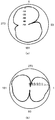
- FIG. 5 is a flowchart showing an example of the operation for the switching sequence in FIG. 4 for the radiation control unit 21 in FIG. 1. It is a figure which shows an example of the measured directivity pattern of (a) horizontal and (b) vertical in the external multi-antenna system used in experiment. It is a figure which shows an example of the received spectrum waveform in experiment.
- FIG. 3 is a diagram illustrating an arrangement example different from FIG. 2 with respect to the communication antennas 29 1 ,..., 29 n of FIG. It is a figure which shows the size (pattern 1) of transmission power (pulse amplitude) as a characteristic example other than the length of packet length, and whether the packet exists in a certain fixed area (pattern 2).
- Example of this invention it is a flowchart which shows the outline
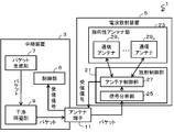
- FIG. 1 is a block diagram showing an outline of a packet communication system 1 according to an embodiment of the present invention.
- the packet communication system 1 includes a relay device 3 that generates a packet (an example of a “relay device” in the claims of the present application), and a switching control packet (the switching control packet will be specifically described later) among the generated packets.
- a radio wave radiation device 5 (an example of a “radio wave radiation device” in the claims of the present application) is provided that analyzes characteristics other than the above-described contents and controls the radiation direction and / or radiation intensity.
- the relay device 3 can be realized without changing the wireless interface in an existing relay wireless device.
- the radio wave radiation device 5 is a multi-antenna system that is externally connected to the relay device 3.
- the relay device 3 includes a control unit 6 that controls the operation of the entire device, a packet generation unit 7 that generates a packet (an example of a “packet generation unit” in the claims of this application), and transmission of an unintended packet by CSMA / CA or the like.
- An interference avoidance unit 9 that causes timing fluctuations and an antenna terminal 11 (an example of “antenna terminal” in the claims of the present application) to which the radio wave radiation device 5 is connected are provided.
- the radio wave radiation device 5 includes a directional antenna unit 23 (an example of a “directional antenna unit” in the claims of the present application) that can control the radiation direction and / or the radiation intensity, and the radiation direction and / or the directional antenna unit 23.
- the radiation control part 21 (an example of the "radiation control apparatus" of this-application claim) which controls radiation intensity and radiates
- the directional antenna unit 23 includes a plurality of communication antennas 29 1 ,..., 29 n (an example of “communication antenna” in the claims of the present application) (hereinafter, subscripts are omitted except when referring to specific ones).
- the communication antenna 29 is a directional antenna that radiates radio waves strongly in a specific direction with respect to radio wave radiation direction and radiation intensity.
- FIG. 2 is a diagram illustrating an arrangement of communication antennas in the present embodiment.
- the relay device 31 (an example of the relay device in FIG. 1) includes four antenna terminals.
- the radio wave emission device 33 (an example of the radio wave emission device 5 in FIG. 1) includes four switches 35 1 , 35 2 , 35 3 and 35 4 .
- the switches 35 1 , 35 2 , 35 3 and 35 4 are connected to different antenna terminals, respectively, and the antennas 37 1 and 39 1 , 37 2 and 39 2 , 37 3 and 39 3 and 37 4 and 39 4 (FIG. 1).
- the antenna 37 is a dipole antenna and a horizontal antenna.
- the antenna 39 is a dipole antenna and is a vertical antenna.
- the switch 35 emits radio waves from only one of the antennas 37 and 39 having the same subscript.
- the antennas 37 and 39 are arranged so that their planes of polarization are orthogonal to each other and compensate for the antenna directivity null points. With such orthogonal polarization arrangement, antenna control can be performed so as to obtain optimum directivity according to the communication environment. Since radio waves can be emitted in all directions regardless of the installation form of the relay station, stable relay line quality can be ensured.
- the signal analysis unit 25 monitors signals output from all or part of the four antenna terminals and detects a switching control packet.
- the radiation control unit 21 in FIG. 1 includes a signal analysis unit 25 (an example of “signal analysis unit” in the claims) and an antenna control unit 27 (control unit) that controls each communication antenna 29 based on the analysis result.
- the signal analysis unit 25 obtains antenna control information for controlling each transmission antenna 29 by analyzing features other than the content of the switching control packet without analyzing the content.
- the antenna control unit 27 controls the directivity of the directional antenna unit 23 as a whole by controlling the radiation of each transmission antenna 29 based on the antenna control information.
- the antenna control unit 27 sends a signal (reception signal) received by the communication antenna 29 to the control unit 6 via the antenna terminal 11.
- a signal reception signal
- the antenna control unit 27 can measure a predetermined communication antenna and send the received reception signal to the control unit 6.
- the interference avoidance unit 9 of FIG. 1 changes the transmission timing of each packet unintentionally and outputs it from the antenna terminal 11 to the radio wave radiation device 5 as in the interference avoidance function by CSMA / CA, for example.
- each packet is desirably transmitted at the generated timing (pattern A).
- the interference avoidance function causes random fluctuations in the packet transmission timing. For example, fluctuations in transmission timing due to random backoff (pattern B), and packet transmission stoppage (pattern C) to avoid interference occur. Therefore, in order to expand the function of an existing wireless repeater, it is essential to consider the influence of this interference avoidance function.
- the packet generator 7 controls and generates the time from the transmission start time to the transmission end time of each packet according to the value set in the packet length parameter.
- the packet generator 7 controls and generates the transmission power of each packet according to the value set in the transmission power parameter. Further, the packet generator 7 controls the transmission start time of the next packet according to the value set in the transmission time interval parameter.
- the transmission time interval parameter the time from the transmission end time of the previous packet to the transmission start time of the next packet is W0. It is assumed that two types of W1 can be set.
- the transmission power parameter is assumed to be constant.
- the operation of the packet generator 7 is generally controlled by a program incorporated in the apparatus in an existing relay radio. Therefore, if the operation of the packet generator 7 is only changed so as to select a parameter value, it is not necessary to change the hardware, and it can be realized by changing the embedded program.
- the packet generation unit 7 transmits 1 as antenna control information to the signal analysis unit 25, the data size is 200 [bytes], and the parameter value of the packet length P1 is 0.267 [ms]. ] Furthermore, there are cases where two packets are connected and detected due to fluctuations in the transmission timing of the interference avoidance unit 9 (see the fourth and fifth packets of pattern B in FIG. 3). In this case, it becomes difficult for the signal analysis unit 25 to accurately detect the packet length. Therefore, the parameter value of the transmission time interval W1 is set to 4.8 [ms]. Thereby, in the signal analysis part 25, it can avoid fundamentally that a some packet is connected and detected. The interference avoidance unit 9 changes the transmission timing and does not change each packet itself.
- the signal analysis unit 25 focuses on features (packet length) that are not changed by the interference avoidance unit 9 among features (packet length and transmission time interval) other than the contents set by the packet generation unit 7 in each packet. A case where the antenna control information is generated will be described.
- the packet generation unit 7 sets the data size to 650 [bytes], sets the parameter value of the packet length P0 to 0.867 [ms],
- the transmission time interval W0 is set to 5.2 [ms].
- FIG. 4 shows an example in which packets B and C have different data amounts and the packet length is adjusted to P0 by adjusting the symbol length.
- FIG. 4 is a diagram illustrating an example of a transmission signal output to the radio wave emission device 5.
- the transmission signal includes a portion (antenna control signal) for controlling the directivity of the directional antenna unit 23.
- the antenna control signal includes a synchronization control packet indicating a synchronization sequence and a switching control packet indicating a subsequent switching sequence.
- the synchronization control packet and the switching control packet are collectively referred to as a control packet.
- the synchronization control packet is used to distinguish whether the observed packet is a control packet or a normal data packet. For example, control information corresponding to a random sequence such as an M sequence is assigned to the synchronization sequence.
- control information corresponding to a random sequence such as an M sequence is assigned to the synchronization sequence.
- the length of U synchronization control packets is determined based on Equation (1).
- An example of the M series is 1111100110100100001010111011000 (sequence length 31).
- FIG. 5 is a diagram illustrating an example of the synchronization sequence of FIG. As long as the control packet and the normal data packet can be distinguished, other sequences may be used as the synchronization sequence. Only when the detected sequence matches the synchronization sequence, the signal analysis unit 25 regards the subsequent packet as a switching sequence and performs antenna switching control.
- the signal analysis unit 25 determines antenna control information (synchronization sequence information) b ⁇ ⁇ 1, 0 ⁇ based on the equation (1).
- T 1 , T 2, and T 3 are time lengths, and are appropriately adjusted so that the signal analysis unit 25 can correctly detect the antenna control information.
- b [j] be a sequence of values detected by the signal analysis unit 25 at time j.
- the signal analysis unit 25 performs a correlation operation by calculating V [j] according to Equation (3).
- the radiation control unit 21 controls the directivity of the directional antenna unit 23 based on each switching control packet in the switching sequence.
- four packets A, B, C, and D are included.
- Packets A and D have a packet length P1. Therefore, the signal analysis unit 25 identifies the antenna control information as 1.
- Packets B and C have a packet length of P0. Therefore, the signal analysis unit 25 specifies the antenna control information as 0. Thereby, the signal analysis unit 25 specifies 1001 as the whole antenna control information.
- FIG. 6 is a diagram illustrating an example of the switching sequence.
- FIG. 4 shows an example in which the packet length is made constant by adjusting the data amount and the symbol length for the packets B and C.
- packets B and C for example, halving the symbol length doubles the amount of data contained in one packet, but the packet length is the same. This indicates that even when the data rates are different, the packet length is not necessarily variable, and even if it is variable, a plurality of packets cannot always be correctly identified.
- the system of this embodiment observes only the packet length, and any data included in the packet may be used.
- FIG. 7 is a flowchart showing an example of the operation for the synchronization sequence of FIG. 4 for the radiation control unit 21 of FIG.
- the signal analysis unit 25 determines whether or not there is a packet (step S1). When there is no packet, the monitoring is continued until the packet exists. If a packet exists, the packet length W of the packet is observed by measuring the time from the observation start time to the observation end time of the packet (step S2).
- the signal analysis unit 25 obtains the antenna control information b ⁇ ⁇ 1, 0 ⁇ using Expression (1). Specifically, when the signal analysis unit 25 sets W to be T 1 or more and less than T 2 (step S3), the antenna control information b is set to 1 (step S4), and W is T 2 or more and less than T 3. In the case (step S5), the antenna control information b is set to 0 (step S6).
- the correlation calculation of equation (2) is performed to check whether the currently detected sequence matches a known synchronization sequence (step S7). If it matches the synchronization sequence, the process ends (step S8), and the process proceeds to detection of a switching sequence. If none of the conditional expressions in steps S3 and S5 correspond, it is regarded as a false detection and the process returns to the synchronous sequence detection process.
- W is less than T 1 or more than T 3 and erroneously detected, for example, there is a possibility that it is a normal data packet or a possibility that a plurality of packets are connected and detected. In that case, it is considered that control information is not transmitted.
- the synchronization sequence is transmitted in order to prevent malfunction due to an identification error with a normal data packet.
- the packet interval is adjusted in advance so that a plurality of packets are not connected and detected.
- FIG. 8 is a flowchart showing an example of the operation for the switching sequence of FIG. 4 for the radiation control unit 21 of FIG. First, the switch 35 1 of the switching control in FIG. 2 for (step ST1), specifically described.
- the signal analyzer 25 determines whether or not a packet exists (step ST11). When there is no packet, the monitoring is continued until the packet exists. When a packet exists (packet A in FIG. 4), the packet length W is observed by measuring the time from the observation start time to the observation end time of the packet (step ST12).
- the signal analysis unit 25 obtains antenna control information b ⁇ ⁇ 1, 0 ⁇ by comparison with the value of T 2 .
- the antenna control information b is set to 1 when W ⁇ T 2
- the antenna control information b is set to 0 otherwise.
- the antenna control unit 27 controls the switch 35 1 to select the antenna 37 1 (horizontal antenna) or the antenna 39 1 (vertical antenna).
- T 2 is a time length and is appropriately adjusted so that the signal analysis unit 25 can correctly detect the antenna control information.
- switching control (step ST2) of switch 35 2 by the packet B in FIG. 4 the switching control (step ST3) of the switch 35 3 by the packet C of FIG. 4, and the switching of the switch 35 4 by the packet D in FIG. 4
- the control (step ST4) can be similarly realized.
- FIG. 9 is an example of (a) horizontal and (b) vertical measured directivity patterns in the external multi-antenna system used in this experiment. Also, the synchronization sequence length of the control signal in FIG. 4 is 15, and T 1 , T 2, and T 3 are 200, 800, and 1400 [ ⁇ sec], respectively.
- FIG. 10 is a diagram illustrating an example of a received spectrum waveform.
- the reception spectrum is different between horizontal polarization and vertical polarization. Therefore, it can be confirmed that the effect of improving the relay line quality can be obtained by adaptively switching the antenna directivity according to the installation form of the relay station.
- antenna control signal (relay packet) was attempted 100 times in an actual device of a relay radio and a multi-antenna system. The antenna was confirmed to be switched correctly in all those trials.
- the present invention is not limited to the arrangement shown in FIG. 2, and the number of antenna terminals and the number of antennas are not limited to a specific number.
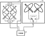
- a radio wave radiation device 43 an example of the radio wave radiation device 5 in FIG. 1 or a radio wave radiation device 45 (the radio wave radiation device in FIG. 1) connected to the relay device 41 (an example of the relay device 3 in FIG. 1). 5
- the number of antenna terminals and the number of antennas are not limited to a specific number.
- one switch may be configured to switch and control three or more antennas.
- FIG. 2 shows a configuration for performing antenna switching control.
- the present invention is not limited to this, and for example, input / output signals for each antenna may be adaptively weighted and used.
- the relay device 3 When weighting the input / output signal for each antenna, for example, the relay device 3 notifies the radio wave radiation device 5 of the weight information using the antenna control signal.
- this may be realized by a configuration in which a code book (correspondence table) in which weight information and control bits are associated is prepared in advance and a control bit corresponding to the weight information is notified using an antenna control signal.
- the antenna control information has been described in association with the length of the packet length.
- the present invention is not limited to this, for example, a method of changing the parameter of the transmission power to associate the antenna control information with the magnitude of the transmission power (pulse amplitude) of the packet (see pattern 1 in FIG. 12), transmission You may implement
- the relay device cannot accurately realize fluctuations such as rising of the transmission power.
- even in a radio wave emission device it may be difficult to accurately measure this.
- the interference avoiding unit 9 causes a deviation due to random fluctuations in the transmission timing.
- it is not realistic to take measures until the transmission is stopped see pattern C in FIG. 3.
- fluctuations due to random backoff see pattern B in FIG. 3
- transmission stop does not always occur and depends on the surrounding environment. For this reason, as the observation period, an observation period that is longer than the period during which fluctuation due to random backoff may occur is set, and the transmission stop may be dealt with by, for example, transmitting a packet a plurality of times.
- the periodic intermittent transmission method (IPT: Intermittent Periodic Transmit Forwarding) is used.
- IPT Intermittent Periodic Transmit Forwarding
- a node connected to a wired line is defined as a core node
- a node connected only to a relay line to another node is defined as a slave node.
- a relay line from the core node to the slave node is defined as a downlink
- a relay line from the slave node to the core node is defined as an uplink.
- IPT is one of packet relay transmission methods in wireless backhaul. IPT is roughly divided into two stages. The first stage is a state in which a route is determined, and a downlink and an uplink are determined. The second stage is a normal use state, in which a downlink data packet is intermittently transmitted periodically at a transmission source node (core node).
- core node transmission source node
- IPT In IPT, by adjusting the frequency repetition use interval on the relay path to an appropriate value, interference can be suppressed and high relay transmission efficiency can be achieved.
- the inventors have proposed directional IPT as a protocol in which IPT is extended for directional antennas (see, for example, International Publication No. 2009/123112 pamphlet).
- directional IPT is adopted as a packet relay protocol. The method based on the minimum propagation loss routing is adopted for the relay path construction, and the Bellman-Ford algorithm is used for searching for the minimum propagation loss route.
- each slave node periodically switches directional antennas, and evaluates various combinations of directional antennas, so that the combination of the path with the smallest metric and the directional antenna is autonomous. Is to choose. Without the positional information of each slave node, it becomes possible to autonomously select a directional antenna that minimizes the sum of the propagation loss of the path from each slave node to the core node.
- FIGS. 13 and 14 are flowcharts showing an example of a procedure for forming a relay route in each slave node.
- the slave node first, processing when a route formation packet is received is performed, and then transmission processing of the route formation packet is performed.
- the core node only a route formation packet transmission process is performed. Therefore, the operation of the core node is basically the same as the processing at the time of transmitting the route formation packet in FIG.
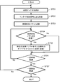
- FIG. 13 is a flowchart showing an outline of a processing procedure in each node at the time of transmitting a route formation packet.
- the antenna control unit 27 in FIG. 1 randomly selects any one of the communication antennas 29 1 ,..., 29 n and performs transmission antenna switching control using an antenna control signal (step STS1).
- the packet generator 7 broadcasts a route formation packet (step STS2).
- the antenna control unit 27 waits for a response (route formation packet) from the node that has received the route formation packet (step STS3).
- the control unit 6 registers the currently selected transmission antenna number and information included in the route formation packet in the downlink node list (step STS5).
- the route formation packet includes information on all downlink node numbers that can be reached via the source node of the route formation packet. If a path formation packet has been received from the same node in the past, the information is updated to the latest one.
- a series of processing relating to the selected transmission antenna is repeated until a predetermined time elapses (step STS6). When a certain time has elapsed, the transmitting antenna is switched again at random, and the same processing is performed (step STS7). The above processing is repeated until there is no change in the relay route.
- FIG. 14 is a flowchart showing an outline of a processing procedure in each slave node when a route formation packet is received.
- the control unit 6 in FIG. 1 initializes a metric (step STR1).
- the metric is an index corresponding to the quality of the relay line between the nodes. For example, the reception power of the relay packet can be used as the metric.
- the antenna control unit 27 randomly selects a reception antenna (step STR2), and performs switching control based on the antenna control signal (step STR3).
- the control unit 6 calculates a metric (step STR5) and compares it with a past retained metric (step STR6).
- step STR7 If the metric is smaller than the retained metric, the retained metric is updated to the currently calculated one (step STR7), and the source of the route formation packet is registered as the parent node (step STR8). If the parent node has already been registered, the information is updated to the latest one.
- the route formation packet is transmitted to the source node of the route formation packet (step STR9). If the calculated metric value is larger than the retained metric, the transmission source of the route formation packet is confirmed (step STR10). When the transmission source node is a parent node, a route formation packet is notified to the transmission source node (step STR9). The above processing is repeated until a predetermined time has elapsed (step STR11).
- a downlink and an uplink are autonomously determined by transmission / reception of a route formation packet.
- a route is determined by transmitting and receiving route formation packets every time in operation. Therefore, for normal data packets other than the route formation packet, the directional antenna used for transmission / reception is constant.
- the packet generation unit 7 of FIG. 1 refers to the path formed by the control unit 6 for the node that is the transmission destination of each packet with respect to the radio wave radiation device 5, and the radiation direction and / or radiation intensity thereof. (Especially, the radiation direction) can be specified. Similarly, it is possible to assume a communication antenna for the received signal in advance. (More generally, it is possible to determine the reception direction.) Therefore, the antenna control unit 27 can measure a predetermined communication antenna and send the received reception signal to the control unit 6. it can.
- the present invention has a remarkable effect in the directional IPT that assumes transmission / reception of data packets in a static node arrangement.
- the characteristics of the wireless backhaul system using the multi-antenna system and the directional IPT in this embodiment are evaluated by computer simulation.
- the relay transmission characteristics when used in combination with a packet relay protocol for a directional antenna are evaluated by computer simulation.
- the assumed two-dimensional node arrangement is the West Building No. 2 building 8th floor model of Kyushu University.
- the directivity pattern of each antenna is the same as that shown in FIG.
- the PHY / MAC conforms to IEEE802.11a, and the PHY transmission rate is 54 Mbps.
- DCF Distributed Coordination Function
- the required value of SINR is 10 dB. If the received packet quality (SINR observed value) is equal to or higher than the required value, reception is successful with probability 1. Otherwise, probability 1 is assumed.
- FIG. 15 is an example of a relay route constructed in the node arrangement of the above model.
- FIG. 16 shows the method of the present embodiment (multi-antenna w / IPT) in which the antenna switching control is performed to form the relay route and the conventional route formation method using the omni-directional antenna (omni-antenna w / IPT). It is a figure which shows a system throughput characteristic. The vertical axis represents throughput (Throughput), and the horizontal axis represents call volume (Total offered load). From FIG. 16, it was confirmed that the throughput characteristic was improved by about 12.6% by the method of this example compared with the conventional route formation method.
Landscapes
- Engineering & Computer Science (AREA)
- Computer Networks & Wireless Communication (AREA)
- Signal Processing (AREA)
- Mobile Radio Communication Systems (AREA)
- Radio Transmission System (AREA)
- Radio Relay Systems (AREA)
Abstract
CSMA/CA等によりパケットの送信タイミングの揺らぎを生じる中継無線機であっても、中継無線機の無線インターフェースは変更せず、アンテナ指向性の自動調整を実現可能なパケット通信システム等を提案する。干渉回避部9は、CSMA/CA等の処理によりパケットの送信タイミングの揺らぎを生じさせる。電波放射装置5は、放射方向及び/又は放射強度を制御可能である。パケット生成部7は、放射方向及び/又は放射強度を特定するための切替系列に基づいて、内容以外の特徴(例えばパケット長や送信強度など)を変更して切替制御パケットを生成する。放射制御部21は、切替制御パケットの内容以外の特徴等を観測して、アンテナ制御情報として、一つ又は複数のビットを特定する。放射制御部21は、特定された一つ又は複数のビットを含むビット系列に基づいて、指向性アンテナ部23全体としての指向性を制御する。
Description
本発明は、パケット通信システム、放射制御装置、アンテナ制御方法及びプログラムに関し、特に、放射方向及び/又は放射強度を制御してパケットを送信するパケット通信システム等に関する。
次世代モバイルブロードバンドを実現する形態の1つとして、無線バックホールを利用したWi-Fiアクセスネットワーク網が注目されている。無線バックホールとは、基地局同士を無線で接続した通信ネットワークのことである。無線バックホールは、有線回線に接続されたコア基地局を起点とした無線中継網(メッシュネットワーク)を構築することにより、サービスエリアをカバーすることができる。無線バックホールは、コア基地局に多数の無線中継基地局を接続して運用することにより、有線回線の敷設コストを抑えることができる。そのため、低コストかつ柔軟にエリアを拡大・変更することが可能となる。
無線バックホールにおける中継回線品質は、中継無線機のアンテナ指向性や設置形態に依存する。中継無線機は、一般に、天井裏や壁面などに設置される。そのため、建物の什器の配置や景観上の理由により設置場所の制約を受けることが多い。したがって、無線バックホールにおいて、設置形態やアンテナの向きに依存せず安定した中継回線品質を得るには、設置形態などに応じてアンテナ指向性を自動調整することが有効である。
複数のアンテナを用いて通信品質を向上させることは、例えば特許文献1及び特許文献2に記載されている。特許文献1には、送信信号の通信速度の値によって、垂直偏波用のアンテナと水平偏波用のアンテナのいずれかを用いて通信を行うことにより、信号間の干渉を軽減して周波数利用効率を上げることが記載されている。特許文献2には、送信波に対する移動端末の出力の測定値によって、垂直偏波と水平偏波のいずれかを送受信電波として割り当てることが記載されている。
しかしながら、アンテナ指向性を自動調整する従来の技術は、当初から、自動調整するための機能を備えることを前提としていた。そのため、例えばIEEE802.11準拠の無線モジュールを採用する中継無線機に対して、アンテナ指向性を自動調整するように機能を拡張するためには、外付けのアンテナを変更するだけでは足りず、中継無線機の無線インターフェースの変更が事実上必要であった。
すなわち、各パケットについて、外付けのアンテナにおいて、各パケットの内容を分析して送信先の情報を得て、アンテナ指向性を自動調整するのであれば、外付けのアンテナの処理の負担が極端に増大することになる。そのため、既存の中継無線機を利用する場合には、外付けのアンテナにおいて、各パケットの内容自体を分析することなく、アンテナ指向性を自動調整させる必要がある。
そのためには、中継無線機は、外付けのアンテナに対して、各パケットの内容とは別に情報を与える必要がある。これを実現させるためには、送信信号においてダミーパケット等を用いて新たな情報を付加する方法と、送信信号とは別に情報を与える方法が考えられる。
しかし、例えばIEEE802.11準拠の無線モジュールを採用する中継無線機は、干渉信号を自動的に検出し、それを回避する機能が備わっている(CSMA/CA(Carrier Sense Multiple Access with Collision Avoidance)による干渉回避機能)。そのため、パケットの送信タイミングに揺らぎが生じる。すなわち、パケットが指定のタイミングで送信されない(ランダムバックオフ)、パケットが送信されない(パケット送信停止)等の現象が発生する。そのため、中継無線機が、単純に、ダミーパケット等によりアンテナ指向性を調整するためには、CSMA/CAによる干渉回避機能を削除する等のハードウエア的な変更が必要になる。
また、送信信号とは別に情報を与える場合にも、アンテナ端子とは別に端子を設ける必要があり、無線インターフェースの変更が必要になる。
そこで、本発明は、例えばIEEE802.11準拠の無線モジュールを採用してCSMA/CA等によりパケットの送信タイミングの揺らぎを生じる中継無線機であっても、中継無線機の無線インターフェースは変更せず、アンテナ指向性の自動調整を実現可能なパケット通信システム等を提案することを目的とする。
本願発明の第1の観点は、放射方向及び/又は放射強度を制御してパケットを送信するパケット通信システムであって、中継装置と電波放射装置とを備え、前記中継装置は、前記電波放射装置が接続されるアンテナ端子と、前記放射方向及び/又は前記放射強度を特定する切替系列に含まれる一つ又は複数のビットに対応して、内容以外の特徴を変更して切替制御パケットを生成し、前記アンテナ端子を経由して前記電波放射装置に出力するパケット生成手段を備えるものであり、前記電波放射装置は、前記放射方向及び/又は前記放射強度を制御可能な指向性アンテナ部と、前記切替制御パケットの内容以外の特徴を分析することにより、一つ又は複数のビットの値を特定する信号分析手段と、前記指向性アンテナ部に対して、前記特定された一つ又は複数のビットを含むビット系列に基づいて前記放射方向及び/又は前記放射強度を制御するアンテナ制御手段とを備えるものである。
本願発明の第2の観点は、第1の観点であって、前記パケット生成手段は、前記切替系列に含まれる一つ又は複数のビットに対応して、パケット長のパラメータ及び/又は送信電力のパラメータを変更して、前記切替制御パケットを生成することにより、前記切替制御パケットの内容以外の特徴を変更し、前記信号分析手段は、前記切替制御パケットのパケット長及び/又は送信電力を分析することにより前記一つ又は複数のビットの値を特定するものである。
本願発明の第3の観点は、第1又は第2の観点であって、前記指向性アンテナ部は、複数の通信アンテナを有し、前記複数の通信アンテナは、指向性アンテナであって、ある前記通信アンテナのヌル点となる方向が、他の前記通信アンテナによって補われるものであり、前記切替系列は、前記複数の通信アンテナの一部を指定し、又は、前記各通信アンテナの重み情報を指定し、又は、前記複数の通信アンテナの一部を指定して、指定された前記各通信アンテナの重み情報を指定するものであり、前記アンテナ制御手段は、前記ビット系列に基づいて、前記指定された一部の通信アンテナに対して電波を放射させ、又は、前記指定された重み情報を用いて信号を合成して電波を放射させ、又は、前記指定された一部の通信アンテナに対して、前記重み情報を用いて信号を合成して電波を放射させる。
本願発明の第4の観点は、第1から第3のいずれかの観点であって、前記中継装置は、前記パケット生成手段が、前記電波放射装置に対して、前記切替制御パケットを出力する場合に、前記切替制御パケットの生成処理とは無関係に、自動的に、生成された前記切替制御パケットの送信タイミングを変更させる干渉回避部を備え、前記信号分析手段が分析する前記切替制御パケットの内容以外の特徴は、前記干渉回避部による送信タイミングの変更後も維持されるものである。
本願発明の第5の観点は、第1から第4のいずれかの観点であって、前記パケット生成手段は、前記切替制御パケットと他のパケットを区別するための同期制御パケットを生成し、続いて、前記切替制御パケットの生成を制御するものであって、前記切替系列に含まれる一つ又は複数のビットが所定値又は所定値の組み合わせである場合に、特定の時間間隔において、前記切替制御パケットを生成せず、前記信号分析手段は、前記同期制御パケットを検出し、続いて、特定の時間間隔において前記切替制御パケットを検出しない場合に、一つ又は複数のビットの値を前記所定値又は前記所定値の組み合わせと特定する。
本願発明の第6の観点は、一つ又は複数のコアノードと複数のスレーブノードとを含み、各ノード間で無線通信を行うパケット通信システムにおいて、前記コアノード及び前記複数のスレーブノードの一部又は全部は、中継装置と電波放射装置を備えるものであり、前記コアノード及び前記各スレーブノードは、いずれかのノードの位置が変更した場合又は前記コアノード若しくは前記スレーブノードが増減した場合、経路形成パケットを送受信して、前記コアノードから前記各スレーブノードに至る経路である下り回線及び前記各スレーブノードから前記コアノードに至る経路である上り回線を決定するものであり、これにより、前記中継装置及び前記放射制御装置を備えるノードは、前記経路形成パケット以外にノード間で送受信されるデータパケットについて、当該ノードが前記データパケットを送信するノードに対応して前記放射制御装置の放射方向及び/又は放射強度を決定し、及び、当該ノードに対して前記データパケットを送信するノードに対応して前記放射制御装置の受信方向を決定するものであり、前記中継装置は、前記電波放射装置が接続されるアンテナ端子と、前記放射方向及び/又は前記放射強度を特定する切替系列に含まれる一つ又は複数のビットに対応して、内容以外の特徴を変更して切替制御パケットを生成し、前記アンテナ端子を経由して前記電波放射装置に出力するパケット生成手段を備えるものであり、前記電波放射装置は、前記放射方向及び/又は前記放射強度を制御可能な指向性アンテナ部と、前記切替制御パケットの内容以外の特徴を分析することにより、一つ又は複数のビットの値を特定する信号分析手段と、前記指向性アンテナ部に対して、前記特定された一つ又は複数のビットを含むビット系列に基づいて前記放射方向及び/又は前記放射強度を制御し、前記中継装置に対して、前記アンテナ端子を経由して、前記受信方向を観測して得られた受信信号を出力するアンテナ制御手段とを備えるものである。
本願発明の第7の観点は、アンテナ端子に接続され、放射方向及び/又は放射強度を制御可能な指向性アンテナ部に対して、前記放射方向及び/又は前記放射強度を制御する放射制御装置であって、前記アンテナ端子を観測して検出された切替制御パケットの内容以外の特徴を分析することにより、一つ又は複数のビットの値を特定する信号分析手段と、前記指向性アンテナ部に対して、前記特定された一つ又は複数のビットを含むビット系列に基づいて前記放射方向及び/又は前記放射強度を制御するアンテナ制御手段とを備えるものである。
本願発明の第8の観点は、放射方向及び/又は放射強度を制御するアンテナ制御方法であって、アンテナ端子を観測して検出された切替制御パケットの内容以外の特徴を分析することにより、一つ又は複数のビットの値を特定する信号分析ステップと、放射方向及び/又は放射強度を制御可能な指向性アンテナ部に対して、前記特定された一つ又は複数のビットを含むビット系列に基づいて前記放射方向及び/又は前記放射強度を制御する制御ステップを含むものである。
本願発明の第9の観点は、コンピュータを、アンテナ端子を観測して検出された切替制御パケットの内容以外の特徴を分析することにより、一つ又は複数のビットの値を特定する信号分析手段と、放射方向及び/又は放射強度を制御可能な指向性アンテナ部に対して、前記特定された一つ又は複数のビットを含むビット系列に基づいて前記放射方向及び/又は前記放射強度を制御するアンテナ制御手段として機能させるためのプログラムである。
なお、「A及び/又はB」は、「A又はB又はその両方」という意味である。また、本願発明を、コンピュータを、パケット生成手段として機能させるためのプログラムとして捉えてもよい。また、プログラムを(定常的に)記録するコンピュータ読み取り可能な記録媒体や、プログラム製品として捉えてもよい。
また、切替制御パケットは、他のノードとの間で送受されるデータパケットとは区別される制御パケットの一つである。例えば、パケット生成手段は、切替制御パケットと他のデータパケットを区別するための同期制御パケットを生成し、続いて、切替制御パケットを生成するものとし、さらに、信号分析手段は、同期制御パケットを検出し、続いて、検出されたパケットを、切替制御パケットと判断して、内容以外の特徴を分析するものであってもよい。なお、信号分析手段は、切替制御パケットと他のパケットとを区別して切替制御パケットに対して分析を行えばよく、同期制御パケットを用いる方法に限定されない。また、信号分析手段が分析する切替制御パケットの内容以外の特徴は、前記干渉回避部による送信タイミングの変更による影響を除去することにより維持されるものであってもよい。さらに、信号分析手段が観測する特定の時間間隔は、前記干渉回避部による送信タイミングの変更を考慮して決定する(例えば、一部のタイミング変更の上限期間以上の時間間隔とする)ことにより、前記干渉回避部による送信タイミングの変更の一部又は全部の影響が除去されるものであってもよい。
本願各請求項に係る発明(以下、「本発明」という。)によれば、中継装置は、CSMA/CA等を採用して切替制御パケットの送信タイミングの揺らぎを生じる中継無線機であっても、パケット生成手段の動作並びに外付けのアンテナである電波放射装置の構成及び動作を変更することにより、パケットそのものを利用して、アンテナ指向性を自動調整することが可能になる。そのため、既存の無線中継局のハードウエア構成は基本的に維持しつつ、外付けのアンテナを変更することにより、マルチアンテナ化することができる。特に、切替制御パケットの内容以外の特徴(例えばパケット長や送信電力など)は、タイミングの調整によっても維持される。そのため、より確実にマルチアンテナ化を実現することができる。
さらに、本願発明の第5の観点にあるように、周期的間欠送信法(IPT:Intermittent Periodic Transmit Forwarding)においては、データパケットは、基本的に静的なノード配置において送受信される。そのため、中継装置は、電波放射装置に対して、各データパケットの送受信先となるノードについて、その放射方向及び/又は放射強度(特に、放射方向・受信方向)を指定して自動調整させることが有効であり、顕著な効果を得ることができる。
以下では、図面を参照して、本発明の実施例について説明する。なお、本発明は、これらの実施例に限定されるものではない。
図1は、本発明の実施例であるパケット通信システム1の概要を示すブロック図である。パケット通信システム1は、パケットを生成する中継装置3(本願請求項の「中継装置」の一例)と、生成されたパケットのうち切替制御パケット(切替制御パケットについては後に具体的に説明する。)の内容以外の特徴を分析して放射方向及び/又は放射強度を制御する電波放射装置5(本願請求項の「電波放射装置」の一例)を備える。中継装置3は、既存の中継無線機において、無線インターフェースを変更せずに実現することが可能である。電波放射装置5は、中継装置3に外付けで接続されたマルチアンテナシステムである。
中継装置3は、装置全体の動作を制御する制御部6と、パケットを生成するパケット生成部7(本願請求項の「パケット生成手段」の一例)と、CSMA/CA等により意図しないパケットの送信タイミングの揺らぎを生じさせる干渉回避部9と、電波放射装置5が接続されるアンテナ端子11(本願請求項の「アンテナ端子」の一例)を備える。
電波放射装置5は、放射方向及び/又は放射強度を制御可能な指向性アンテナ部23(本願請求項の「指向性アンテナ部」の一例)と、指向性アンテナ部23に対して放射方向及び/又は放射強度を制御して電波を放射させる放射制御部21(本願請求項の「放射制御装置」の一例)を備える。
指向性アンテナ部23は、複数の通信アンテナ291,…,29n(本願請求項の「通信アンテナ」の一例)(以下、添え字は、特定のものを指す場合以外は省略する。)を備える。通信アンテナ29は、電波の放射方向と放射強度について、特定の方向へ強く電波を放射する指向性アンテナである。
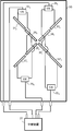
図2は、本実施例における通信アンテナの配置を示す図である。中継装置31(図1の中継装置の一例)は、4つのアンテナ端子を備える。電波放射装置33(図1の電波放射装置5の一例)は、4つのスイッチ351、352、353及び354を備える。スイッチ351、352、353及び354は、それぞれ、異なるアンテナ端子に接続し、アンテナ371及び391、372及び392、373及び393並びに374及び394(図1の通信アンテナ29の一例)を切替制御する。ここで、アンテナ37は、ダイポールアンテナであり、水平アンテナであるとする。アンテナ39は、ダイポールアンテナであり、垂直アンテナであるとする。スイッチ35により、添え字が共通するアンテナ37と39の一方のみから電波放射される。アンテナ37及び39は、偏波面が互いに直交し、アンテナ指向性のヌル点を互いに補うように配置されている。このような直交偏波配置により、通信環境に応じて最適な指向性となるようにアンテナ制御が可能である。中継局の設置形態によらず全方向への電波放射が可能となるので、安定した中継回線品質を確保することができる。信号分析部25は、4つのアンテナ端子の全て又は一部から出力された信号を監視して、切替制御パケットを検出する。
図1の放射制御部21は、切替制御パケットを分析する信号分析部25(本願請求項の「信号分析手段」の一例)と、分析結果により各通信アンテナ29を制御するアンテナ制御部27(本願請求項の「アンテナ制御手段」の一例)とを備える。信号分析部25は、切替制御パケットを、内容を分析することなく、内容以外の特徴を分析することにより、各送信アンテナ29を制御するためのアンテナ制御情報を得る。アンテナ制御部27は、アンテナ制御情報に基づき各送信アンテナ29の放射を制御して、指向性アンテナ部23の全体としての指向性を制御する。
また、アンテナ制御部27は、通信アンテナ29において受信された信号(受信信号)を、アンテナ端子11を経由して制御部6に送る。例えば、指向性IPTでは、後に図14(特にステップSTR2)を用いて説明するように、他のノードが送信したデータパケットを受信する通信アンテナは、予め決定されている。そのため、アンテナ制御部27は、予め決定された通信アンテナを計測して、受信した受信信号を制御部6へ送ることができる。
図1の干渉回避部9は、例えばCSMA/CAによる干渉回避機能のように、各パケットの送信タイミングを意図せず変更し、アンテナ端子11から電波放射装置5に対して出力するものである。
ここで、図3を参照して、CSMA/CAによる干渉回避機能について説明する。理想的には、各パケットは、生成されたタイミングで送信されることが望ましい(パターンA)。しかし、干渉回避機能により、パケットの送信タイミングにランダムな揺らぎが生じる。例えば、ランダムバックオフによる送信タイミングの揺らぎ(パターンB)や、干渉回避のためにパケット送信の停止(パターンC)などが生じる。そのため、既存の無線中継機を機能拡張するためには、この干渉回避機能による影響を考慮することが不可欠である。
図1のパケット生成部7は、複数のパケットを、所定のパラメータに従って生成する。パラメータは、図示を省略するパラメータ記憶部に記憶されている。パラメータには、例えば、パケット長のパラメータ(あるパケットの送信開始時刻から送信終了時刻までの時間長)、送信電力のパラメータ、送信時間間隔のパラメータ(あるパケットの送信開始時刻又は送信終了時刻から次のパケットの送信開始時刻までの時間)などが存在する。パケット生成部7は、パケット長のパラメータに設定された値に従って、各パケットの送信開始時刻から送信終了時刻までの時間を制御して生成する。また、パケット生成部7は、送信電力のパラメータに設定された値に従って、各パケットの送信電力を制御して生成する。さらに、パケット生成部7は、送信時間間隔のパラメータに設定された値に従って、次のパケットの送信開始時刻を制御する。
本実施例では、各パラメータに、複数の値が設定可能なものが存在する。以下では、その一例として、パケット長について、P0又はP1の2種類設定可能であり、送信時間間隔のパラメータについて、前のパケットの送信終了時刻から次のパケットの送信開始時刻までの時間がW0とW1の2種類設定可能であるとする。送信電力のパラメータは、一定であるとする。パケット生成部7の動作は、既存の中継無線機では、一般的に、装置に組み込まれたプログラムにより制御されている。そのため、パケット生成部7の動作について、パラメータ値を選択するように変更するのみであれば、ハードウエアとしての変更は必要なく、組込プログラムの変更によって実現することができる。
本実施例では、パケット生成部7は、信号分析部25に対して、アンテナ制御情報として1を伝える場合には、データサイズを200[byte]とし、パケット長P1のパラメータの値を0.267[ms]とする。さらに、干渉回避部9の送信タイミングの揺らぎによって2つのパケットが繋がって検出される場合がある(図3のパターンBの4番目及び5番目のパケット参照)。この場合、信号分析部25が、パケット長を正確に検出することが困難になる。そのため、送信時間間隔W1のパラメータの値を4.8[ms]とする。これにより、信号分析部25において、複数のパケットが繋がって検出されることを基本的に回避することができる。干渉回避部9は、送信タイミングを変更するものであり、各パケットそのものは変更しない。そのため、以下では、信号分析部25は、パケット生成部7が各パケットに設定した内容以外の特徴(パケット長及び送信時間間隔)のうち、干渉回避部9により変更されない特徴(パケット長)に着目してアンテナ制御情報を生成する場合について説明する。
また、パケット生成部7は、信号分析部25に対して、アンテナ制御情報として0を伝える場合には、データサイズを650[byte]とし、パケット長P0のパラメータの値を0.867[ms]とし、送信時間間隔W0を5.2[ms]とする。(ただし、図4では、パケットBとCでは、異なるデータ量とし、シンボル長を調整することにより、パケット長をP0にした例を示している。)
図4は、電波放射装置5に出力される送信信号の一例を示す図である。送信信号には、指向性アンテナ部23の指向性を制御するための部分(アンテナ制御信号)が含まれている。アンテナ制御信号には、同期系列を示す同期制御パケットと、それに続く切替系列を示す切替制御パケットが含まれている。以下では、同期制御パケットと切替制御パケットを併せて制御パケットという。
同期制御パケットは、観測されたパケットが、制御パケットと通常のデータパケットとのいずれであるのかを区別するためのものである。同期系列には、例えば、M系列等のランダム系列に対応する制御情報が割り当てられる。同期系列の一例として0と1から構成される系列長UのM系列を用いる場合、式(1)に基づき、U個の同期制御パケットの長さを決定する。M系列の例としては、1111100110100100001010111011000(系列長31)があげられる。図5は、図4の同期系列の一例を示す図である。制御パケットと通常のデータパケットを区別可能であれば、その他の系列を同期系列として用いてもよい。信号分析部25は、検出された系列が同期系列と一致した場合のみ、後続のパケットを切替系列とみなしてアンテナの切替制御を行う。
信号分析部25において同期系列を検出する方法としては、例えば、以下の方法を用いる。同期系列として系列長UのM系列X[i],i=1,2,…,Uを用いる。信号分析部25は、式(1)に基づき、アンテナ制御情報(同期系列情報)b∈{1,0}を決定する。ここで、T1、T2及びT3は、時間長であり、信号分析部25がアンテナ制御情報を正しく検出できるように適切に調整されている。そして、式(2)にあるように、信号分析部25が時刻jにおいて検出した値の列をb[j]とする。信号分析部25は、式(3)によりV[j]を計算することにより、相関演算を行う。信号分析部25は、V[j]=Uとなるとき、後続のパケットの情報を切替系列とみなす。

放射制御部21は、切替系列における各切替制御パケットに基づき、指向性アンテナ部23の指向性を制御する。図4では、4つのパケットA、B、C及びDが含まれている。パケットA及びDは、パケット長がP1である。そのため、信号分析部25は、アンテナ制御情報を1と特定する。パケットB及びCは、パケット長がP0である。そのため、信号分析部25は、アンテナ制御情報を0と特定する。これにより、信号分析部25は、アンテナ制御情報全体として、1001であると特定する。図6は、切替系列の一例を示す図である。
なお、図4では、パケットBとCについて、データ量とシンボル長を調整することによりパケット長を一定にした例を示している。パケットB及びCにあるように、例えば、シンボル長を半分にすることで1パケットに含まれるデータ量が倍となるものの、パケット長は同じである。これは、データ速度が異なる場合でもパケット長が可変になるとは限らず、また可変にしたとしても複数のパケットを正しく識別できるとは限らないことを示している。本実施例の方式は、パケット長のみを観測するものであり、パケットに含まれるデータは何であってもよい。
図7は、図1の放射制御部21について、図4の同期系列に対する動作の一例を示すフロー図である。
信号分析部25は、パケットが存在するか否かを判断する(ステップS1)。パケットが存在しない場合には、パケットが存在するまで継続して監視する。パケットが存在する場合、そのパケットの観測開始時刻から観測終了時刻までの時間を計測することにより、そのパケットのパケット長Wを観測する(ステップS2)。
信号分析部25は、式(1)を用いてアンテナ制御情報b∈{1,0}を得る。具体的な処理は、信号分析部25が、WがT1以上T2未満である場合(ステップS3)、アンテナ制御情報bを1とし(ステップS4)、WがT2以上T3未満である場合(ステップS5)、アンテナ制御情報bを0とする(ステップS6)。式(2)の相関演算を行い、現在検出された系列が既知の同期系列と一致するかどうかを検査する(ステップS7)。同期系列と一致する場合は終了し(ステップS8)、切替系列の検出に移行する。ステップS3,S5の条件式のいずれにも該当しない場合は、誤検出とみなし、同期系列の検出処理に戻る。
WがT1未満又はT3以上として誤検出となる場合には、例えば通常のデータパケットである可能性や複数のパケットが繋がって検出された可能性などが考えられる。その場合は、制御情報が送信されてないとみなされる。同期系列は、通常のデータパケットとの識別誤りによる誤動作を防ぐために送信されるものである。また、パケット間隔は、複数のパケットが繋がって検出されることのないように、事前に調整されている。
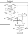
図8は、図1の放射制御部21について、図4の切替系列に対する動作の一例を示すフロー図である。まず、図2のスイッチ351の切替制御(ステップST1)について、具体的に説明する。
信号分析部25は、パケットが存在するか否かを判断する(ステップST11)。パケットが存在しない場合には、パケットが存在するまで継続して監視する。パケットが存在する場合(図4のパケットA)、そのパケットの観測開始時刻から観測終了時刻までの時間を計測することにより、パケット長Wを観測する(ステップST12)。
信号分析部25は、T2の値と比較してアンテナ制御情報b∈{1,0}を得る。具体的には、W<T2の場合にアンテナ制御情報bを1とし、そうでない場合にアンテナ制御情報bを0とする。図4のパケットAは、bが1と判断される。これにより、アンテナ制御部27は、スイッチ351を制御して、アンテナ371(水平アンテナ)又はアンテナ391(垂直アンテナ)を選択する。T2は時間長であり、信号分析部25がアンテナ制御情報を正しく検出できるように適切に調整されている。
続いて、図4のパケットBによるスイッチ352の切替制御(ステップST2)、図4のパケットCによるスイッチ353の切替制御(ステップST3)、及び、図4のパケットDによるスイッチ354の切替制御(ステップST4)についても、同様に、実現することができる。
続いて、図9及び図10を参照して、発明者らが開発した小型中継無線機と外付けマルチアンテナシステムを用いた実験結果を説明する。
図9は、本実験で用いた外付けマルチアンテナシステムにおける(a)水平・(b)垂直の実測指向性パターンの一例である。また、図4の制御信号の同期系列長を15とし、T1、T2及びT3は、それぞれ、200、800及び1400[μsec]とする。
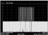
そして、九州大学校舎内において、2つの中継局間の伝搬路特性(受信スペクトル)を測定した。図10は、受信スペクトル波形の一例を示す図である。水平偏波と垂直偏波で受信スペクトルが異なる。そのため、中継局の設置形態に応じてアンテナ指向性を適応的に切り替えることにより、中継回線品質を改善する効果が得られることを確認できる。
さらに、中継無線機及びマルチアンテナシステムの実機において、アンテナ制御信号(中継パケット)の送信を100回試みた。アンテナは、それらの全ての試行で正しく切り替えられていることを確認した。
なお、本発明は、図2のような配置に限定されず、アンテナ端子の数及びアンテナの数は、特定の数に限定されるものではない。例えば、図11において、中継装置41(図1の中継装置3の一例)に接続する電波放射装置43(図1の電波放射装置5の一例)や、電波放射装置45(図1の電波放射装置5の他の一例)にあるように、アンテナ端子の数及びアンテナの数は、特定の数に限定されるものではない。また、例えば、一つのスイッチが3つ以上のアンテナを切替制御するようにしてもよい。
また、図2は、アンテナの切替制御を行う構成を示したものである。本発明は、これに限定されず、例えば、アンテナ毎の入出力信号を適応的に重み付けして利用してもよい。アンテナ毎の入出力信号の重み付けを行う場合、例えば、中継装置3は、電波放射装置5に対して、アンテナ制御信号を用いて重み情報を通知する。これは、例えば、重み情報と制御ビットを対応づけたコードブック(対応表)を事前に準備し、アンテナ制御信号を用いて重み情報に対応する制御ビットを通知する構成により実現してもよい。
さらに、本実施例では、アンテナ制御情報をパケット長の長短に対応づけて説明した。本発明は、これに限定されず、例えば、送信電力のパラメータを変更して、パケットの送信電力(パルス振幅)の大小にアンテナ制御情報を対応づける方法(図12のパターン1参照)や、送信時間間隔を変更して、ある一定区間内にパケットが存在するかどうかにアンテナ制御情報を対応づける方法(図12のパターン2参照)によって実現してもよい。ただし、送信電力のパラメータを変更する場合、中継装置において、送信電力の立ち上がり等の変動を精確に実現できない場合も考えられる。さらに、電波放射装置においても、これを精確に計測することが困難な場合が考えられる。また、送信時間間隔を変更した場合、干渉回避部9により送信タイミングのランダムな揺らぎによりズレが生じる。これに対応するためには、揺らぎが生じる期間以上の観測区間を設けることが考えられる。しかし、送信停止(図3のパターンC参照)まで対策することは、現実的ではない。ランダムバックオフによる揺らぎ(図3のパターンB参照)は常に生じるものであるのに対し、送信停止は、常に生じるものではなく、周囲の環境に依存するものである。そのため、観測区間としては、ランダムバックオフによる揺らぎが生じ得る期間以上の観測区間を設定し、送信停止については、例えば、パケットを複数回送信する等により対応することが考えられる。
本実施例では、コアノードに多数のスレーブノードを接続して運用する無線バックホールにおいて、各ノードの無線通信を本発明により実現する場合に、周期的間欠送信法(IPT:Intermittent Periodic Transmit Forwarding)を採用したときについて説明する。ここで、有線回線に接続されるノードをコアノード、中継回線のみで他ノードに接続されるノードをスレーブノードと定義する。また、コアノードからスレーブノードへ向かう中継回線を下り回線、スレーブノードからコアノードへ向かう中継回線を上り回線と定義する。
IPTは、無線バックホールにおけるパケット中継伝送方式の一つである。IPTは、大きく2段階に分かれる。第1段階は、経路を決定する状態であり、下り回線及び上り回線を決定する。第2段階は、通常の使用状態であり、送信源ノード(コアノード)において、下り回線のデータパケットを周期的に間欠送信する。
IPTでは、中継経路上の周波数繰り返し利用間隔を適切な値に調整することで、干渉を抑制し、高い中継伝送効率を達成できる。また、発明者らは、IPTを指向性アンテナ用に拡張したプロトコルとして、指向性IPTが提案している(例えば国際公開第2009/123112号パンフレット参照)。本実施例では、パケット中継プロトコルとして、指向性IPTを採用する。中継経路構築には最小伝搬損ルーティングに基づく手法を採用し、伝搬損失最小ルートの探索にはBellman-Fordアルゴリズムを用いる。
指向性IPTの特徴は、各スレーブノードが定期的に指向性アンテナを切り替えながら、多様な指向性アンテナの組み合わせを評価することにより、メトリックが最小となる経路と指向性アンテナの組み合わせを自律的に選択することである。各スレーブノードの位置情報なしに、各スレーブノードからコアノードまでに至る経路の伝搬損失の和が最小となる指向性アンテナの自律選択が可能となる。
図13及び図14は、各スレーブノードにおける中継経路形成処理手順の一例を示すフロー図である。スレーブノードでは、まず、経路形成パケット受信時の処理を行い、その後、経路形成パケットの送信処理が行われる。コアノードでは、経路形成パケットの送信処理のみが行われる。そのため、コアノードの動作は、基本的に、図13の経路形成パケット送信時の処理と同様である。
図13は、経路形成パケット送信時の各ノードにおける処理手順の概要を示すフロー図である。まず、図1のアンテナ制御部27は、通信アンテナ291,…,29nのいずれかをランダムに選択し、アンテナ制御信号により送信アンテナの切替制御を行う(ステップSTS1)。次に、パケット生成部7は、経路形成パケットをブロードキャスト送信する(ステップSTS2)。アンテナ制御部27は、経路形成パケットを受信したノードからの応答(経路形成パケット)を待つ(ステップSTS3)。経路形成パケットが受信された場合(ステップSTS4)、制御部6は、現在選択されている送信アンテナ番号と経路形成パケットに含まれている情報を下りノードリストに登録する(ステップSTS5)。経路形成パケットには、経路形成パケットの送信元ノードを経由して到達可能な全ての下り回線のノード番号の情報が含まれている。過去に同じノードから経路形成パケットを受信済みである場合は、その情報を最新のものに更新する。選択された送信アンテナに関する一連の処理を一定時間が経過するまで繰り返す(ステップSTS6)。一定時間が経過すると送信アンテナを再度ランダムに切り替えて同じ処理を行う(ステップSTS7)。上述の処理を中継経路の変更がなくなるまで繰り返す。
図14は、経路形成パケット受信時の各スレーブノードにおける処理手順の概要を示すフロー図である。まず、図1の制御部6は、メトリックを初期化する(ステップSTR1)。メトリックは、ノード間の中継回線品質に対応する指標であり、例えば中継パケットの受信電力をメトリックとして用いることができる。アンテナ制御部27は、受信アンテナをランダムに選択し(ステップSTR2)、アンテナ制御信号により切替制御を行う(ステップSTR3)。経路形成パケットが受信された場合(ステップSTR4)、制御部6は、メトリックを計算し(ステップSTR5)、過去の保持メトリックと比較する(ステップSTR6)。メトリックが保持メトリックよりも小さい場合、保持メトリックを現在計算したものに更新し(ステップSTR7)、経路形成パケットの送信元を親ノードとして登録する(ステップSTR8)。親ノードを既に登録済みである場合は、その情報を最新のものに更新する。経路形成パケットの送信元ノードに経路形成パケットを送信する(ステップSTR9)。計算したメトリック値が保持メトリックよりも大きい場合は、経路形成パケットの送信元を確認する(ステップSTR10)。送信元ノードが親ノードである場合は、経路形成パケットを送信元ノードに通知する(ステップSTR9)。上記の処理を一定時間が経過するまで繰り返す(ステップSTR11)。
IPTでは、経路形成パケットの送受信により、下り回線及び上り回線が自律的に決定される。ノードが増減した場合やいずれかのノードの位置が変更した場合などには、運用上、その都度、経路形成パケットを送受信して、経路が決定される。そのため、経路形成パケット以外の通常のデータパケットについては、送受信に用いられる指向性アンテナは、一定である。
よって、図1のパケット生成部7は、電波放射装置5に対して、各パケットの送信先となるノードについて、制御部6により形成された経路を参照して、その放射方向及び/又は放射強度(特に、放射方向)を指定することが可能になる。また、受信信号についても、同様に、予め、通信アンテナを想定することが可能である。(より一般的には、受信方向を決定することが可能である。)そのため、アンテナ制御部27は、予め決定された通信アンテナを計測して、受信した受信信号を制御部6へ送ることができる。
よって、本発明は、静的なノード配置においてデータパケットの送受信を前提とする指向性IPTにおいて、顕著な効果を有するものである。
続いて、図15及び図16を参照して、本実施例におけるマルチアンテナシステムおよび指向性IPTを用いる無線バックホールシステムの特性を計算機シミュレーションにより評価する。本発明を無線バックホールに適用した場合について、指向性アンテナ用のパケット中継プロトコルと併用する場合の中継伝送特性を計算機シミュレーションにより評価する。
本検討の評価に際し、想定した2次元ノード配置は、九州大学のWest2号館8階モデルである。各アンテナの指向性パターンは、図9のものを用いる。提案方式の有効性を示すために、IPTプロトコルを用いる無指向性アンテナシステムの特性との比較を行う。PHY/MACはIEEE802.11aに準拠するものとし、PHYの伝送レートを54Mbpsとする。また、MAC層モデルとしてDCF(Distributed Coordination Function)/basicモードを仮定する。SINR(Signal to interference and noise power ratio)の所要値を10dBとし、受信したパケットの品質(SINR観測値)が当該所要値以上の場合は確率1で受信に成功し、そうでない場合は確率1で受信に失敗すると仮定する。パケットの受信に失敗した場合(SINR観測値が所要値を満たさない場合)は、最大7回までの再送を行う。再送に全て失敗した場合は、パケットロスとする。トラフィックは、各ノードにおいて、ポアソン生起により発生し、1パケットバーストあたりのパケット数は対数正規分布に従うものとする。また、上下総トラフィック比は1:10とし、シャドウウィングは、壁一枚当たり12[dB]とする。評価パラメータとしてシステムスループット特性を採用した。図15は、上記モデルのノード配置において構築された中継経路の例である。図16は、アンテナ切替制御を行い中継経路を形成する本実施例の手法(multi-antenna w/IPT)と、従来の無指向性アンテナを用いる経路形成手法(omni-antenna w/IPT)とのシステムスループット特性を示す図である。縦軸はスループット(Throughput)であり、横軸は呼量(Total offered load)である。図16より、本実施例の手法により、従来の経路形成手法に比べて、スループット特性を約12.6%改善したことが確認された。
1 パケット通信システム、3 中継装置、5 電波放射装置、6 制御装置、7 パケット生成部、9 干渉回避部、11 アンテナ端子、21 放射制御部、23 指向性アンテナ部、25 信号分析部、27 アンテナ制御部、291,…,29n 通信アンテナ
Claims (9)
- 放射方向及び/又は放射強度を制御してパケットを送信するパケット通信システムであって、
中継装置と電波放射装置とを備え、
前記中継装置は、
前記電波放射装置が接続されるアンテナ端子と、
前記放射方向及び/又は前記放射強度を特定する切替系列に含まれる一つ又は複数のビットに対応して、内容以外の特徴を変更して切替制御パケットを生成し、前記アンテナ端子を経由して前記電波放射装置に出力するパケット生成手段を備えるものであり、
前記電波放射装置は、
前記放射方向及び/又は前記放射強度を制御可能な指向性アンテナ部と、
前記切替制御パケットの内容以外の特徴を分析することにより、一つ又は複数のビットの値を特定する信号分析手段と、
前記指向性アンテナ部に対して、前記特定された一つ又は複数のビットを含むビット系列に基づいて前記放射方向及び/又は前記放射強度を制御するアンテナ制御手段とを備えるパケット通信システム。 - 前記パケット生成手段は、前記切替系列に含まれる一つ又は複数のビットに対応して、パケット長のパラメータ及び/又は送信電力のパラメータを変更して、前記切替制御パケットを生成することにより、前記切替制御パケットの内容以外の特徴を変更し、
前記信号分析手段は、前記切替制御パケットのパケット長及び/又は送信電力を分析することにより前記一つ又は複数のビットの値を特定する、請求項1に記載のパケット通信システム。 - 前記指向性アンテナ部は、複数の通信アンテナを有し、
前記複数の通信アンテナは、指向性アンテナであって、ある前記通信アンテナのヌル点となる方向が、他の前記通信アンテナによって補われるものであり、
前記切替系列は、
前記複数の通信アンテナの一部を指定し、又は、
前記各通信アンテナの重み情報を指定し、又は、
前記複数の通信アンテナの一部を指定して、指定された前記各通信アンテナの重み情報を指定するものであり、
前記アンテナ制御手段は、前記ビット系列に基づいて、
前記指定された一部の通信アンテナに対して電波を放射させ、又は、
前記指定された重み情報を用いて信号を合成して電波を放射させ、又は、
前記指定された一部の通信アンテナに対して、前記重み情報を用いて信号を合成して電波を放射させる、請求項1又は2に記載のパケット通信システム。 - 前記中継装置は、前記パケット生成手段が、前記電波放射装置に対して、前記切替制御パケットを出力する場合に、前記切替制御パケットの生成処理とは無関係に、自動的に、生成された前記切替制御パケットの送信タイミングを変更させる干渉回避部を備え、
前記信号分析手段が分析する前記切替制御パケットの内容以外の特徴は、前記干渉回避部による送信タイミングの変更後も維持されるものである、請求項1から3のいずれかに記載のパケット通信システム。 - 前記パケット生成手段は、
前記切替制御パケットと他のパケットを区別するための同期制御パケットを生成し、続いて、前記切替制御パケットの生成を制御するものであって、
前記切替系列に含まれる一つ又は複数のビットが所定値又は所定値の組み合わせである場合に、特定の時間間隔において、前記切替制御パケットを生成せず、
前記信号分析手段は、前記同期制御パケットを検出し、続いて、特定の時間間隔において前記切替制御パケットを検出しない場合に、一つ又は複数のビットの値を前記所定値又は前記所定値の組み合わせと特定する、
請求項1から4のいずれかに記載のパケット通信システム。 - 一つ又は複数のコアノードと複数のスレーブノードとを含み、各ノード間で無線通信を行うパケット通信システムにおいて、
前記コアノード及び前記複数のスレーブノードの一部又は全部は、中継装置と電波放射装置を備えるものであり、
前記コアノード及び前記各スレーブノードは、いずれかのノードの位置が変更した場合又は前記コアノード若しくは前記スレーブノードが増減した場合、経路形成パケットを送受信して、前記コアノードから前記各スレーブノードに至る経路である下り回線及び前記各スレーブノードから前記コアノードに至る経路である上り回線を決定するものであり、これにより、前記中継装置及び前記放射制御装置を備えるノードは、前記経路形成パケット以外にノード間で送受信されるデータパケットについて、当該ノードが前記データパケットを送信するノードに対応して前記放射制御装置の放射方向及び/又は放射強度を決定し、及び、当該ノードに対して前記データパケットを送信するノードに対応して前記放射制御装置の受信方向を決定するものであり、
前記中継装置は、
前記電波放射装置が接続されるアンテナ端子と、
前記放射方向及び/又は前記放射強度を特定する切替系列に含まれる一つ又は複数のビットに対応して、内容以外の特徴を変更して切替制御パケットを生成し、前記アンテナ端子を経由して前記電波放射装置に出力するパケット生成手段を備えるものであり、
前記電波放射装置は、
前記放射方向及び/又は前記放射強度を制御可能な指向性アンテナ部と、
前記切替制御パケットの内容以外の特徴を分析することにより、一つ又は複数のビットの値を特定する信号分析手段と、
前記指向性アンテナ部に対して、前記特定された一つ又は複数のビットを含むビット系列に基づいて前記放射方向及び/又は前記放射強度を制御し、前記中継装置に対して、前記アンテナ端子を経由して、前記受信方向を観測して得られた受信信号を出力するアンテナ制御手段とを備える、パケット通信システム。 - アンテナ端子に接続され、放射方向及び/又は放射強度を制御可能な指向性アンテナ部に対して、前記放射方向及び/又は前記放射強度を制御する放射制御装置であって、
前記アンテナ端子を観測して検出された切替制御パケットの内容以外の特徴を分析することにより、一つ又は複数のビットの値を特定する信号分析手段と、
前記指向性アンテナ部に対して、前記特定された一つ又は複数のビットを含むビット系列に基づいて前記放射方向及び/又は前記放射強度を制御するアンテナ制御手段とを備える放射制御装置。 - 放射方向及び/又は放射強度を制御するアンテナ制御方法であって、
アンテナ端子を観測して検出された切替制御パケットの内容以外の特徴を分析することにより、一つ又は複数のビットの値を特定する信号分析ステップと、
放射方向及び/又は放射強度を制御可能な指向性アンテナ部に対して、前記特定された一つ又は複数のビットを含むビット系列に基づいて前記放射方向及び/又は前記放射強度を制御する制御ステップを含むアンテナ制御方法。 - コンピュータを、
アンテナ端子を観測して検出された切替制御パケットの内容以外の特徴を分析することにより、一つ又は複数のビットの値を特定する信号分析手段と、
放射方向及び/又は放射強度を制御可能な指向性アンテナ部に対して、前記特定された一つ又は複数のビットを含むビット系列に基づいて前記放射方向及び/又は前記放射強度を制御するアンテナ制御手段として機能させるためのプログラム。
Priority Applications (1)
| Application Number | Priority Date | Filing Date | Title |
|---|---|---|---|
| US13/821,722 US8937986B2 (en) | 2010-09-08 | 2011-09-07 | Packet communication system, emission control apparatus, antenna control method and computer program |
Applications Claiming Priority (2)
| Application Number | Priority Date | Filing Date | Title |
|---|---|---|---|
| JP2010201144A JP5493131B2 (ja) | 2010-09-08 | 2010-09-08 | パケット通信システム、放射制御装置、アンテナ制御方法及びプログラム |
| JP2010-201144 | 2010-09-08 |
Publications (1)
| Publication Number | Publication Date |
|---|---|
| WO2012033124A1 true WO2012033124A1 (ja) | 2012-03-15 |
Family
ID=45810721
Family Applications (1)
| Application Number | Title | Priority Date | Filing Date |
|---|---|---|---|
| PCT/JP2011/070366 Ceased WO2012033124A1 (ja) | 2010-09-08 | 2011-09-07 | パケット通信システム、放射制御装置、アンテナ制御方法及びプログラム |
Country Status (4)
| Country | Link |
|---|---|
| US (1) | US8937986B2 (ja) |
| JP (1) | JP5493131B2 (ja) |
| TW (1) | TWI517619B (ja) |
| WO (1) | WO2012033124A1 (ja) |
Cited By (1)
| Publication number | Priority date | Publication date | Assignee | Title |
|---|---|---|---|---|
| CN105340358A (zh) * | 2014-04-22 | 2016-02-17 | 华为技术有限公司 | 一种天线系统、中继站及数据传输方法 |
Families Citing this family (3)
| Publication number | Priority date | Publication date | Assignee | Title |
|---|---|---|---|---|
| GB201309953D0 (en) * | 2013-06-04 | 2013-07-17 | Renesas Mobile Corp | Method and apparatus for controlling parameters of an antenna tuner |
| CN104694345B (zh) * | 2013-11-06 | 2017-09-12 | 广东宏益鳄鱼产业有限公司 | 鳄鱼肺保健酒及其制备方法 |
| US9853863B1 (en) | 2014-10-08 | 2017-12-26 | Servicenow, Inc. | Collision detection using state management of configuration items |
Citations (2)
| Publication number | Priority date | Publication date | Assignee | Title |
|---|---|---|---|---|
| JP2003037549A (ja) * | 2001-07-24 | 2003-02-07 | Toshiba Tec Corp | 無線通信システム |
| JP2005341531A (ja) * | 2004-04-27 | 2005-12-08 | Matsushita Electric Ind Co Ltd | 無線通信システム及び無線局 |
Family Cites Families (9)
| Publication number | Priority date | Publication date | Assignee | Title |
|---|---|---|---|---|
| JP3612010B2 (ja) | 2000-08-18 | 2005-01-19 | 日本電信電話株式会社 | 偏波制御システムおよびその制御方法 |
| JP4460226B2 (ja) | 2002-02-21 | 2010-05-12 | パナソニック株式会社 | 無線基地局装置、無線端末装置及び無線通信方法 |
| DE50302681D1 (de) * | 2002-11-26 | 2006-05-11 | Siemens Ag | Verfahren zum automatischen konfigurieren von kommunikationsbeziehungen zwischen in einem paketorientierten kommunikationsnetz angeordneten kommunikationseinheiten |
| CN1947355A (zh) | 2004-04-27 | 2007-04-11 | 松下电器产业株式会社 | 无线通信系统和无线台 |
| US8159954B2 (en) * | 2005-03-08 | 2012-04-17 | Telefonaktiebolaget Lm Ericsson (Publ) | Method and arragement for advanced routing metrics in multihop networks |
| US8050559B2 (en) * | 2006-08-21 | 2011-11-01 | Juniper Networks, Inc. | Multi-chassis router with multiplexed optical interconnects |
| JP4409579B2 (ja) * | 2007-01-25 | 2010-02-03 | Smk株式会社 | Rf通信システム |
| ITTO20080370A1 (it) * | 2008-05-16 | 2009-11-17 | Selex Communications Spa | Architettura e metodo di gestione del traffico di una rete di sensori di sorveglianza |
| US20110158340A1 (en) * | 2009-12-28 | 2011-06-30 | Qualcomm Incorporated | Virtual antenna array for wireless devices |
-
2010
- 2010-09-08 JP JP2010201144A patent/JP5493131B2/ja active Active
-
2011
- 2011-09-07 US US13/821,722 patent/US8937986B2/en active Active
- 2011-09-07 TW TW100132250A patent/TWI517619B/zh active
- 2011-09-07 WO PCT/JP2011/070366 patent/WO2012033124A1/ja not_active Ceased
Patent Citations (2)
| Publication number | Priority date | Publication date | Assignee | Title |
|---|---|---|---|---|
| JP2003037549A (ja) * | 2001-07-24 | 2003-02-07 | Toshiba Tec Corp | 無線通信システム |
| JP2005341531A (ja) * | 2004-04-27 | 2005-12-08 | Matsushita Electric Ind Co Ltd | 無線通信システム及び無線局 |
Cited By (1)
| Publication number | Priority date | Publication date | Assignee | Title |
|---|---|---|---|---|
| CN105340358A (zh) * | 2014-04-22 | 2016-02-17 | 华为技术有限公司 | 一种天线系统、中继站及数据传输方法 |
Also Published As
| Publication number | Publication date |
|---|---|
| US8937986B2 (en) | 2015-01-20 |
| US20130272345A1 (en) | 2013-10-17 |
| TW201212574A (en) | 2012-03-16 |
| JP5493131B2 (ja) | 2014-05-14 |
| JP2012060382A (ja) | 2012-03-22 |
| TWI517619B (zh) | 2016-01-11 |
Similar Documents
| Publication | Publication Date | Title |
|---|---|---|
| EP3453120B1 (en) | Method and system for p2p communications and decentralized spatial sharing in wireless networks with directional transmissions | |
| CN110463269B (zh) | 用于多跳中继定向无线通信的方法和系统 | |
| CN105577291B (zh) | 一种用于无线通信系统中的空闲信道检测方法和系统 | |
| CN109644415A (zh) | 用于传达独立链路的控制信息的方法和装置 | |
| Tran-Dang et al. | Channel-aware energy-efficient two-hop cooperative routing protocol for underwater acoustic sensor networks | |
| JP6667169B2 (ja) | 基地局装置、無線端末装置および無線通信方法 | |
| JP5493131B2 (ja) | パケット通信システム、放射制御装置、アンテナ制御方法及びプログラム | |
| JP7147756B2 (ja) | ビームフォーミング・トレーニングを用いる通信デバイス及び方法 | |
| JP4877778B2 (ja) | 無線装置およびそれを備えた無線通信ネットワーク | |
| JP7846508B2 (ja) | アクセスポイント装置、通信方法、通信システム、及び、プログラム | |
| US11032848B2 (en) | MAC protocol for directive transmissions | |
| Ikeda et al. | Experimental and simulation evaluation of OLSR protocol for mobile ad-hoc networks | |
| Aust et al. | Sector-based RTS/CTS access scheme for high density WLAN sensor networks | |
| JP4767062B2 (ja) | 無線アクセスポイント及びこの無線アクセスポイントを管理する制御装置 | |
| Lu et al. | CRDMAC: an effective circular RTR directional MAC protocol for wireless ad hoc networks | |
| WO2019188270A1 (ja) | 通信装置、通信システム | |
| Umair et al. | Wireless control plane for software defined networks (SDN) in data centers | |
| Verma et al. | A novel MAC protocol for MANETs using smart antenna system | |
| Chen et al. | A range-adaptive directional MAC protocol for wireless ad hoc networks with smart antennas | |
| Agarwal et al. | Avoidance of Hidden Terminal and Exposed terminal problem Using Directional MAC Protocol | |
| Huang et al. | Performance evaluation of wireless multi-hop networks with directional antennas in an indoor radio propagation channel | |
| Sharma et al. | Deafness Avoidance in MANETs through Exchange of Link ID Broadcasts | |
| Shigeyasu et al. | Effects of Directional Receiving for MAC-Level Broadcasting on Wireless Ad Hoc Networks | |
| JP5293761B2 (ja) | 基地局装置及び制御情報の送信条件設定方法 | |
| KR101546198B1 (ko) | 무선 네트워크에서 전력 제어 방법 및 장치 |
Legal Events
| Date | Code | Title | Description |
|---|---|---|---|
| 121 | Ep: the epo has been informed by wipo that ep was designated in this application |
Ref document number: 11823598 Country of ref document: EP Kind code of ref document: A1 |
|
| NENP | Non-entry into the national phase |
Ref country code: DE |
|
| WWE | Wipo information: entry into national phase |
Ref document number: 13821722 Country of ref document: US |
|
| 122 | Ep: pct application non-entry in european phase |
Ref document number: 11823598 Country of ref document: EP Kind code of ref document: A1 |