WO2012029635A1 - 根切り機構、植物栽培装置、及び水耕栽培装置 - Google Patents
根切り機構、植物栽培装置、及び水耕栽培装置 Download PDFInfo
- Publication number
- WO2012029635A1 WO2012029635A1 PCT/JP2011/069207 JP2011069207W WO2012029635A1 WO 2012029635 A1 WO2012029635 A1 WO 2012029635A1 JP 2011069207 W JP2011069207 W JP 2011069207W WO 2012029635 A1 WO2012029635 A1 WO 2012029635A1
- Authority
- WO
- WIPO (PCT)
- Prior art keywords
- plant
- root
- cutting mechanism
- garlic
- root cutting
- Prior art date
- Legal status (The legal status is an assumption and is not a legal conclusion. Google has not performed a legal analysis and makes no representation as to the accuracy of the status listed.)
- Ceased
Links
Images





Classifications
-
- A—HUMAN NECESSITIES
- A01—AGRICULTURE; FORESTRY; ANIMAL HUSBANDRY; HUNTING; TRAPPING; FISHING
- A01G—HORTICULTURE; CULTIVATION OF VEGETABLES, FLOWERS, RICE, FRUIT, VINES, HOPS OR SEAWEED; FORESTRY; WATERING
- A01G31/00—Soilless cultivation, e.g. hydroponics
- A01G31/02—Special apparatus therefor
-
- Y—GENERAL TAGGING OF NEW TECHNOLOGICAL DEVELOPMENTS; GENERAL TAGGING OF CROSS-SECTIONAL TECHNOLOGIES SPANNING OVER SEVERAL SECTIONS OF THE IPC; TECHNICAL SUBJECTS COVERED BY FORMER USPC CROSS-REFERENCE ART COLLECTIONS [XRACs] AND DIGESTS
- Y02—TECHNOLOGIES OR APPLICATIONS FOR MITIGATION OR ADAPTATION AGAINST CLIMATE CHANGE
- Y02P—CLIMATE CHANGE MITIGATION TECHNOLOGIES IN THE PRODUCTION OR PROCESSING OF GOODS
- Y02P60/00—Technologies relating to agriculture, livestock or agroalimentary industries
- Y02P60/20—Reduction of greenhouse gas [GHG] emissions in agriculture, e.g. CO2
- Y02P60/21—Dinitrogen oxide [N2O], e.g. using aquaponics, hydroponics or efficiency measures
Definitions
- the present invention relates to an apparatus for artificially cultivating a plant, and a root cutting mechanism for cutting roots of the cultivated plant.
- garlic is generally often harvested as edible bulbs, but the stems and leaves are also used as vegetables.
- garlic is rich in ajoene, which is said to be applicable to various medical uses in the root part.
- garlic is a crop with little residue.
- Patent Document 1 proposes a cultivation method for efficiently cultivating garlic roots using a hydroponic cultivation system.
- Patent Document 2 proposes a root cutting device for harvesting plant roots.
- a net frame having a mesh through which a germinated plant can pass, and an upper or lower surface of the net frame, or a root that cuts a portion below the net when a cutter passes between a plurality of net frames.
- An apparatus is disclosed.
- Japanese Patent Publication Japanese Patent Laid-Open No. 2010-63414 (published on March 25, 2010)” Japanese Patent Gazette “Japanese Utility Model Publication No. 3-67544 (published July 2, 1991)”
- Roots of plants such as garlic are regenerated even if they are cut once. For this reason, in order to efficiently harvest plant roots in hydroponics, an apparatus that repeatedly harvests plant root portions is required.
- the hydroponics system described in Patent Document 1 is not provided with a configuration for harvesting garlic roots that are hydroponically cultivated. For this reason, in the hydroponic cultivation system described in Patent Document 1, when harvesting garlic roots, it is necessary to remove the garlic that is hydroponically cultivated from the hydroponic cultivation system and then harvest the garlic roots. There is. Thus, the hydroponic cultivation system described in Patent Document 1 has a problem that the efficiency for harvesting roots is poor.
- the rooting device described in Patent Document 2 does not assume the use of roots, and does not consider a cultivation method that continues cultivation after root cutting. For this reason, since the root cutting apparatus described in Patent Document 2 cuts off all the roots of the plant body, it causes a great damage to the growth of the plant after the root cutting.
- the present invention has been made to solve the above-mentioned problems, and its purpose is to suppress the influence on the growth of the plant cultivated by the plant cultivation apparatus and to efficiently harvest the root of the plant. To do.
- the root cutting mechanism of the present invention can be attached to a plant cultivation apparatus for cultivating a plant, and is a root cutting mechanism for cutting the root of the plant, which supports the plant.
- a movable part arranged to be able to be pressed on the support base, and a cutout which is arranged at the tip of the movable part and cuts off the root of the plant leaving a part by pressing the movable part It is characterized by having a part.
- the movable part having the cutting part at the tip is arranged on the support base so that it can be pressed. Thereby, the root of the plant which a support stand supports can be cut out by pushing down the above-mentioned movable part.
- the cutting unit cuts off the root of the plant leaving a part of the root of the plant when the movable unit is pressed.
- the root of the plant can be harvested by suppressing the influence on the growth of the plant by cutting off the root of the plant without cutting all the roots of the plant and leaving a part of the roots. .
- the present invention can be attached to a plant cultivating apparatus for cultivating a plant, and is arranged so that it can be pressed to a support base that supports the plant by a root cutting mechanism for cutting the root of the plant.
- the movable part is provided at the tip of the movable part, and a cutout part that cuts off the root of the plant leaving a part when the movable part is pressed down.
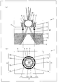
- (A) is sectional drawing showing the structure of the hydroponic cultivation apparatus which concerns on 1st Embodiment
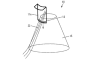
- (b) is a top view of (a). It is a figure explaining the structure of the cutter of the hydroponic cultivation apparatus which concerns on 1st Embodiment. It is a figure explaining harvesting the root of the plant cultivated with the hydroponic cultivation apparatus concerning a 1st embodiment. It is sectional drawing showing the hydroponic cultivation apparatus by which one part was pressed among the some cutters of a root cutting mechanism.
- (b) is a figure showing the hydroponic cultivation apparatus provided with the cutting stand whose cross-sectional shape is a rectangle, (a) was provided with the cutting stand whose side surface does not contact
- FIG. 1 It is a figure showing a hydroponic cultivation apparatus
- (b) is a figure showing the hydroponic cultivation apparatus provided with the cutoff stand which a side surface contacts with the pressed blade.
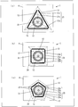
- (A) is a top view showing the hydroponic cultivation apparatus provided with the triangular frustum cutting stand
- (b) is a top view showing the hydroponic cultivation apparatus provided with the quadrangular pyramid cutting stand
- (c) It is a top view showing a hydroponic cultivation apparatus provided with the cutting stand of a pentagonal pyramid.
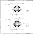
- (A) (b) is a top view showing the hydroponic cultivation apparatus provided with the some cutter distribute
- (A) is a perspective view showing a state of rooting from a scale
- (b) is a plan view showing a rooting part of the scale. It is a figure showing the mode of the hydroponic cultivation apparatus which cuts off a root in the air. It is sectional drawing showing the structure of the hydroponic cultivation apparatus provided with the root cutting mechanism which concerns on 4th Embodiment.
- (A) (b) represents the structure of the hydroponic cultivation apparatus provided with the root cutting mechanism which concerns on 5th Embodiment
- (a) is the hydroponic cultivation apparatus provided with the cutting stand whose cross section is trapezoid. It is a perspective view to represent, (b) is a top view of the hydroponic cultivation apparatus of (a). It is a perspective view showing the hydroponic cultivation apparatus provided with the cutoff stand whose cross section is a triangle.
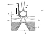
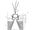
- FIG. 1 is sectional drawing showing the structure of the hydroponic cultivation apparatus 1 which concerns on this Embodiment,
- (b) is a top view of (a).
- Hydroponic cultivation apparatus (plant cultivation apparatus) 1 is a plant cultivation apparatus that grows plants by hydroponics. In the present embodiment, it is assumed that garlic (plant) 30 is cultivated.
- the hydroponic cultivation apparatus 1 mainly includes a culture solution tank 2, a culture solution 3, a shelf board (support stand) 4, and a root cutting mechanism 10.
- the root cutting mechanism 10 can be attached to the hydroponic cultivation apparatus 1 for cultivating plants, and is for cutting the roots of the plants cultivated by the hydroponic cultivation apparatus 1.
- the root cutting mechanism 10 cuts the roots of the plant so as not to cut all the roots of the plant cultivated by the hydroponic cultivation device 1 but to leave a part.
- the root cutting mechanism 10 is arranged on the shelf plate 4 so that it can be pressed (movable part) 11, and is arranged at the tip of the cutter 11.
- a cutting table 15 including a surface that comes into contact with the blade 17 when the cutter 11 is pressed down to the lower limit is the lower limit of the cutter 11.
- the culture solution tank 2 is a water tank for storing the culture solution 3.
- the material of the culture solution tank 2 is not particularly limited, and is made of plastic, concrete, or the like.
- the culture solution 3 is a liquid fertilizer to which necessary nutrients are added according to the plant to be cultivated, and a commonly used liquid fertilizer can be used.
- the shelf board 4 supports a plant that is cultivated by the hydroponic cultivation apparatus 1 and is also a support base that supports a cutter 11 that can be pressed as described later.
- the garlic 30 is placed and cultivated on the shelf board 4.
- the material of the shelf board 4 may be any material that can stably place the plant to be cultivated and can be connected so that the cutter 11 can be pressed, and is made of foamed polystyrene.
- the shelf board 4 As a material of the shelf board 4, as mentioned above, a lightweight material like a polystyrene foam is preferable.
- the shelf board 4 is preferably made of foamed polystyrene having high compression and increased strength. Thereby, since the intensity
- the shelf plate 4 is provided with an opening 7 that can support a bulb (plant) 31 of the garlic 30 that is placed and can pass the root 32 of the garlic 30. .
- the size of the opening 7 provided in the shelf board 4 is determined according to the plant to be cultivated. When the garlic 30 is cultivated as in this embodiment, the diameter of the opening 7 is suitably about 1 to 5 cm, for example.
- the shelf board 4 is installed at such a height that a space is provided between the liquid level of the culture solution 3 and the root of the root 32 of the garlic 30.
- a space is provided between the liquid level of the culture solution 3 and the root of the root 32 of the garlic 30.
- the shelf plate 4 is provided with a plurality of openings 17 for inserting the cutters 11.
- the opening 17 is provided in the shelf board 4 so as to have a shape corresponding to the shape of the blade 12.
- a plurality of openings 17 are also provided on the shelf plate corresponding to the plurality of cutters 11.
- the garlic 30 may be rooted by placing the bulb 31 of the garlic 30 on the shelf 4 as it is, but in the hydroponic cultivation apparatus 1, the bulb 31 of the garlic 30 placed on the shelf 4. Is covered with a protective member composed of the film 5 and the beads 6 so that the root portion is exposed. Thereby, drying of the bulb 31 of the garlic 30 can be prevented.
- the film 5 is made of, for example, a synthetic resin
- the beads 6 are made of, for example, expanded polystyrene.
- a medium provided with an opening that allows passage of the roots of the plant to be cultivated may be provided on the shelf board 4, and the plant to be cultivated may be placed on the medium.
- the cutter 11 is arranged so as to penetrate the shelf board 4, and is for cutting a portion below the shelf board 4 among the plants cultivated by the hydroponic cultivation apparatus 1.
- the cutter 11 includes a plurality of cutters 11a, 11b, 11c, and 11d.
- the plurality of cutters 11a, 11b, 11c, and 11d are arranged around the bulb 31 of the garlic 30 supported by the shelf board 4, and can be pressed independently.
- cutters 11a, 11b, 11c, and 11d are viewed in plan, the cutters 11a, 11b, 11c, and 11d are arranged around the bulb 31 of the garlic 30 supported by the shelf board 4 so as to be circular. Yes.
- cutters 11 a, 11 b, 11 c, and 11 d are arranged surrounding the outer periphery of the film 5 that covers the bulb 31 of the garlic 30.
- the cutters 11a, 11b, 11c, and 11d are configured as a shape obtained by dividing a circular shape into four when viewed in plan.
- the shelf 4 includes a plurality of openings 17a, 11a, 11b, 11c, and 11d as openings 17 into which the cutters 11a, 11b, 11c, and 11d that are arranged around the bulb 31 of the garlic 30 supported by the shelf 4 are inserted. 17b, 17c and 17d are provided. The cutters 11a, 11b, 11c, and 11d are inserted into the openings 17a, 17b, 17c, and 17d, respectively. That is, the openings 17a, 17b, 17c, and 17d are also provided on the shelf board 4 so as to surround the bulb 31 of the garlic 30 when viewed in plan so as to have a circular shape divided into four.
- FIG. 2 is a diagram illustrating the configuration of the cutter 11 of the hydroponic cultivation apparatus 1. Since the cutters 11a, 11b, 11c, and 11d have the same configuration, the configuration of the cutter 11a will be described with reference to FIG.
- the cutter 11a is arranged so as to pass through the opening 17a provided in the shelf board 4, and one end (pressing part) of the cutter 11a is placed on the surface of the shelf board 4 (the bulb 31 of the garlic 30 is mounted).
- the spring 14 which is an elastic member.
- the cutter 11 a is connected to the back surface of the shelf plate 4 (the surface facing the culture solution 3) by a stopper 13. As described above, the operability can be improved by providing the cutter 11 a with the spring 14 and the stopper 13.
- the other end (tip portion) of the cutter 11a is provided with a blade 12 that cuts off the root 32 of the garlic 30 by leaving the cutter 11a pressed.
- the cutters 11a, 11b, 11c, and 11d are arranged on the shelf plate 4 so that they can be pressed independently. For this reason, it is possible to press down the cutter corresponding to the location to be cut among the roots 32 of the garlic 30.
- the cutoff table 15 is installed in the culture solution tank 2 so as to be positioned below the garlic 30.
- the material of the cutoff table 15 can be, for example, plastic such as polypropylene.
- the cutoff table 15 includes a surface that comes into contact with the blades 12 disposed on the cutters 11a, 11b, 11c, and 11d.
- the distance between the surfaces of the cutoff table 15 gradually increases from the top to the bottom. Thereby, when the cutters 11a, 11b, 11c, and 11d are pressed, the blade 12 disposed on the cutter (for example, the cutter 11a) can be brought into contact with the surface of the cutting table 15. Therefore, the root 32 of the garlic 30 can be harvested by pressing the cutters 11a, 11b, 11c, and 11d.
- the shape of the cutoff table 15 is a truncated cone, and its side surface is the surface.
- FIG. 3 is a diagram illustrating that the roots of plants cultivated by the hydroponic cultivation apparatus 1 are harvested.
- the cutting table 15 is arranged such that its side surface comes into contact with the blade 12 arranged on the cutter 11a when the cutter 11a is pressed down to the lower limit.
- the cutting edge of the blade 12 is formed so as to be compatible with the side surface of the cutoff table 15.
- the cutting table 15 which is a truncated cone is installed in the culture solution tank 2 so as to be located below the garlic 30.
- the roots 32 of the garlic 30 will extend along the side surface of the cutting table 15 as it grows.
- the root 32 of the garlic 30 extends along the side surface of the cutting table 15, the root 32 of the garlic 30 is arranged between the blade 12 and the side surface of the cutting table 15. Then, as shown by the arrow in FIG. 3, the cutter 11 a corresponding to the portion to be harvested is pressed among the roots 32 of the garlic 30.
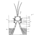
- FIG. 4 is a cross-sectional view showing the hydroponic cultivation apparatus 1 in which some of the cutters 11 are pressed.
- the cutter 11a is pressed.
- the cutter 11c is not pressed.
- the root 32 of the garlic 30 is pressed against the side surface of the cutting table 15 and cut by the blade 12 disposed on the pressed cutter 11a. .
- the root cutting device of Patent Document 2 described above is configured to cut the root of the plant in the lateral direction, all the roots of the plant are cut.
- the root cutting mechanism 10 according to the present embodiment since the cutter 11 is pushed in the vertical direction (vertical direction) instead of in the horizontal direction (horizontal direction), all the roots 32 of the garlic 30 are cut off. Instead, it can be partially left.
- the plurality of cutters 11a, 11b, 11c, and 11d of the root cutting mechanism 10 are arranged so as to surround the garlic 30 supported by the shelf board 4, and can be pressed independently. It is. Therefore, among the cutters 11a, 11b, 11c, and 11d, the root 32 of the garlic 30 is cut only by the blade 12 that is disposed at the tip of the pressed cutter 11a, and the cutters 11b, 11c, and 11d are not pressed. Depending on the blade 12, the root 32 of the garlic 30 is not cut off. That is, the root 32 of the garlic 30 is harvested only by the blade 12 disposed on the pressed cutter 11a, and the other parts are left.
- the root cutting mechanism 10 the influence on the growth of the garlic 30 can be suppressed and the root 32 of the garlic 30 can be harvested.
- the root cutting mechanism 10 includes the cutting base 15 including the side surface that comes into contact with the blade 12 disposed on the cutter 11a when the cutter 11a is pressed down to the lower limit, the root 32 of the garlic 30 is surely cut off.
- the roots 32 of garlic 30 can be harvested efficiently.
- cutter 11a * 11b * 11c * 11d when cutter 11a * 11b * 11c * 11d is planarly viewed, cutter 11a * 11b * 11c * 11d becomes circular shape. Thus, it arrange
- the cutters 11a, 11b, 11c, and 11d are arranged around the bulb 31 of the garlic 30 in accordance with the shape of the truncated cone 15 that is a truncated cone. Can be brought into contact with the side surface of the cutting table 15, and the root 32 of the garlic 30 can be cut out reliably.
- the cutoff table 15 is preferably conical for the following reasons.
- FIG. 5 (A) (b) of Drawing 5 is a figure showing the hydroponic cultivation apparatus provided with the cutting stand whose section shape is a rectangle, and (a) is a cutting stand whose side does not contact a pressed blade. (B) is a figure showing the hydroponic cultivation apparatus provided with the cutting stand which a side surface contacts with the pressed blade.
- the shape of the cutoff table 115 is a columnar shape.
- the cutting table 115 has a circular shape so that the blade 12 disposed at the tip of the cutter 11 does not contact the side surface of the cutting table 115 even when the cutter 11 is pressed.
- the areas of the upper surface and the lower surface of the cutoff table 115 are smaller than the area of the circle formed by the cutters 11a, 11b, 11c, and 11d.
- the cutting table 125 in FIG. 5B has a rectangular cross section. In other words, the shape of the cutoff table 125 is columnar.
- the cutting table 125 has a circular shape such that when the cutter 11 is pressed, the blade 12 disposed at the tip of the cutter 11 and the side surface of the cutting table 125 come into contact with each other.
- the area of the upper surface and the lower surface of the cutting table 115 is larger than the area of the circle formed by the cutters 11a, 11b, 11c, and 11d.
- the roots 32 of the garlic 30 are intricately extended on the upper surface of the cutting table 125 arranged in the horizontal direction. For this reason, the roots 32 of the garlic 30 cut by the pressed blades 12 of the cutter 11 vary in cutting position and length, and the value as a product is reduced.
- the cutter 11 does not necessarily exist below the blade 12 of the pressed cutter 11 a, such as the cutter 11 a. Absent. For this reason, the efficiency of harvesting falls.
- the cutoff table 15 provided in the root cutting mechanism 10 has a frustum shape.
- the area of the upper surface of the cutting table 15 is smaller than the area of the circle constituted by the cutters 11a, 11b, 11c, and 11d, and the area of the lower surface of the cutting table 15 is determined by the cutters 11a and 11b.
- -It is larger than the area of the circle constituted by 11c and 11d.
- the cutting table 15 has a truncated cone shape in accordance with the circular arrangement of the cutters 11a, 11b, 11c, and 11d.
- the side surface of the cutting table 15 is configured to come into contact with the blade 12 disposed on the cutter 11 when the cutter 11 is pressed down to the lower limit.
- the root 32 of the garlic 30 extended along the side surface of the cutting stand 15 can be cut
- the roots 32 of the garlic 30 can be harvested more reliably without reducing the value as a product.
- the cutting table 15 may be a cone shape, and is not limited to a truncated cone shape, and may be a cone shape. Further, as shown in FIGS. 6A to 6C, the cutting table 15 may be a polygonal frustum.
- 6 (a) to 6 (c) are plan views showing a hydroponic cultivation apparatus provided with a root cutting mechanism, (a) showing a hydroponic cultivation apparatus equipped with a triangular pyramid cutout stand, and (b). Represents a hydroponic cultivation apparatus equipped with a truncated pyramid cutout, and (c) represents a hydroponic cultivation apparatus equipped with a pentagonal truncated cutout.
- the cutoff table 22 has a triangular frustum shape.
- the cutter 21 includes a plurality of cutters 21a, 21b, and 21c, and is inserted into the shelf board 4 so as to be triangular when viewed in plan.
- the side surface of the cutting table 22 is configured so as to come into contact with the blade 12 disposed on the cutter 21 when the cutter 21 is pushed down to the lower limit.
- the cutoff table 24 has a quadrangular pyramid shape.
- the cutter 23 includes a plurality of cutters 23a, 23b, 23c, and 23d, and is inserted into the shelf plate 4 so as to be square when viewed in plan.
- the side surface of the cutting table 24 is configured to come into contact with the blade 12 disposed on the cutter 23 when the cutter 23 is pressed down to the lower limit.
- the cutoff table 26 has a pentagonal pyramid shape.
- the cutter 25 includes a plurality of cutters 25a, 25b, 25c, 25d, and 25e, and is inserted into the shelf plate 4 so as to be a pentagon when viewed in plan.
- the side surface of the cutting table 26 is configured to come into contact with the blade 12 disposed on the cutter 25 when the cutter 25 is pressed down to the lower limit.
- the cutting table 22, the cutting table 24, and the cutting table 26 may be a triangular pyramid, a quadrangular pyramid, and a pentagonal pyramid, respectively, and may be a hexagonal pyramid or a polygonal pyramid or a polygonal pyramid that is higher than the hexagonal pyramid. Good.
- the cutters 21a, 21b, 21c, 22a, 22b, 22c, and 23a, 23b, and 23c are viewed in plan, the cutters 21a, 21b, and 21c, 22a, 22b, and 22c, and 23a, 23b, and 23c are polygonal. It is arranged surrounding the bulb 31 of the garlic 30 supported by the shelf board 4 so as to have a shape.
- the bulb 31 can be surrounded and arranged. Thereby, the root 32 of the garlic 30 can be surely cut by pressing each of the cutters 21a, 21b, 21c, 22a, 22b, 22c, 23a, 23b, and 23c.
- the sizes of the cutters 11a, 11b, 11c, and 11d that is, the cutter 11a. It is only necessary to change the size and number of the blades 12 arranged on each of 11b, 11c, and 11d, and it is not necessary to change the shape of the cutting table 15.
- FIG. 7 is a top view showing a hydroponic cultivation device provided with a plurality of cutters arranged circularly, (a) expresses a hydroponic cultivation device provided with a cutter divided into two, (B) is a figure showing the hydroponic cultivation apparatus divided into three.
- the cutter 27 is composed of two divided cutters 27a and 27b, and is inserted into the shelf plate 4 so as to be circular when viewed in plan.
- the side surface of the cutting table 15 is configured to come into contact with the blade 12 disposed on the cutter 27 when the cutter 27 is pressed down to the lower limit.
- the cutter 28 is composed of three divided cutters 28a, 28b, and 28c, and is inserted into the shelf board 4 so as to be circular when viewed in plan.
- the side surface of the cutting table 15 is configured to come into contact with the blade 12 disposed on the cutter 27 when the cutter 27 is pressed down to the lower limit.
- the cutters 11a, 11b, 11c, and 11d do not have to surround the circumference of the bulb 31 of the garlic 30 supported by the shelf board 4 as shown in FIGS. It suffices if it is arranged so as to surround a part of the bulb 31. Further, the cutters 11a, 11b, 11c, and 11d need not always be inserted into the openings 17a, 17b, 17c, and 17d, respectively.
- FIG. 8 is a diagram illustrating a state in which a cutter is inserted into any of a plurality of openings.
- a plurality of cutters 11 a, 11 b, 11 c, and 11 d that surround and surround the bulb 31 of the garlic 30 supported by the shelf board 4 are inserted into the shelf board 4 of the hydroponic cultivation apparatus 1.
- a plurality of openings 17a, 17b, 17c, and 17d are provided, and at least one of the cutters 11a, 11b, 11c, and 11d (for example, the cutter 11a) is any of the openings 17a, 17b, 17c, and 17d. (For example, the opening 17a) may be inserted.
- the cutter 11a can be disposed so as to surround a part of the bulb 31 of the garlic 30 supported by the shelf board 4.
- the cutters 11a, 11b, 11c, and 11d that are inserted into the shelf 4 are provided. It is not necessary to prepare four, and only one of the equally divided parts such as the cutter 11a may be prepared. Thereby, the cost which manufactures the cutter 11 can be reduced.
- the root cutting mechanism 10 for cutting the roots of a plant and attachable to a plant cultivation apparatus for cultivating plants is attached to the hydroponic cultivation apparatus 1. Then, the root cutting mechanism 10 includes the cutters 11a, 11b, 11c, and 11d and the tips of the cutters 11a, 11b, 11c, and 11d, which are arranged to be pressed on the shelf plate 4 that supports the garlic 30. And a blade 12 that cuts off the root 32 of the garlic 30 leaving a part when the cutters 11a, 11b, 11c, and 11d are pressed.
- the cutters 11a, 11b, 11c, and 11d having the blades 17 disposed at the tips are arranged on the shelf plate 4 so that they can be pressed.
- root 32 of the garlic 30 which the shelf board 4 supports can be cut off by pressing down cutter 11a * 11b * 11c * 11d.
- the garlic 30 may not absorb water and nutrients until new roots 32 grow, and the garlic 30 may be weakened or withered.
- the blade 17 cuts out the root 32 of the garlic 30 while leaving any part of the root 32 of the garlic 30 by pressing one of the cutters 11a, 11b, 11c, and 11d.
- the root 32 of the garlic 30 is harvested by suppressing the influence on the growth of the garlic 30 by cutting out the root 32 of the garlic 30 without cutting all the roots 32 of the garlic 30 and leaving a part. be able to.
- the hydroponics apparatus 1 since the hydroponics apparatus 1 is equipped with the root cutting mechanism 10, it suppresses the influence which it has on the growth of the garlic 30 cultivated by the hydroponics apparatus 1, and the root of the garlic 30 efficiently. 32 can be harvested.
- the plant which the hydroponic cultivation apparatus 1 grows demonstrated as what is the garlic 30.
- the plant cultivated by the hydroponic device 1 to which the root cutting mechanism 10 is attached may be a plant that needs to harvest roots.
- the root portion is used as a herbal medicine or a herbal medicine. Plants can be listed.
- the root cutting mechanism 10 of this Embodiment should just be attached to the apparatus which grows a plant, for example, spray culture etc. which spray and grow a mist-like culture solution on a root other than the hydroponic cultivation apparatus 1 etc. You may attach to the apparatus of.
- Embodiment 2 A second embodiment of the root cutting mechanism of the present invention will be described.
- members having the same functions as those in the drawings described in Embodiment 1 are given the same reference numerals, and descriptions thereof are omitted.
- FIG. 9 is a cross-sectional view showing a configuration of a hydroponic cultivation apparatus provided with a root cutting mechanism according to the second embodiment.
- the hydroponic cultivation apparatus 1 includes a root cutting mechanism 41.
- the root cutting mechanism 41 is different from the root cutting mechanism 10 in that it includes a cutting table 45 in place of the cutting table 15 and further includes a bubble generating tube (air stone) 46.
- the root cutting mechanism 41 includes a cutter 11, a blade 12, a stopper 13, a spring 14, a cutoff table 45, and a bubble generating tube 46.
- the bubble generating tube 46 is an air stone for supplying oxygen (gas) to the culture solution 3, and outputs oxygen as a large number of bubbles.
- the bubble generating tube 46 is connected to an air supply pump (not shown) provided outside the cutoff table 45 by a hollow tube 48.
- the bubble generation tube 46 may output oxygen to the culture solution 3 and may output a gas containing oxygen such as air as bubbles.
- the cutting table 45 is installed in the culture solution tank 2 so as to be located below the garlic 30, similarly to the cutting table 15.
- the cutout table 45 has a bubble generating tube 46 disposed therein.
- a plurality of openings 47 through which oxygen output from the bubble generating tube 46 passes are provided on the side surface (surface) of the cutoff table 45.
- the shape, material, etc. of the cutting table 45 are the same as those of the cutting table 15.
- the roots 32 of the garlic 30 are formed by forming a plurality of openings 47 through which oxygen can pass through the cutting table 45. It is possible to effectively distribute oxygen to the part. According to the root cutting mechanism 41, oxygen can be effectively supplied to the roots 32 of the garlic 30 cultivated by the hydroponic cultivation apparatus 1 provided with the cutting table 45.
- the cutting table 45 has a cone shape such as a cone or a truncated cone. For this reason, in order to generate many bubbles by disposing the bubble generating tube 46 in the vicinity of the lower surface where the space inside the cutoff table 45 is large, the bubble generating tube 46 having a relatively large installation area is removed. Can be installed inside.
- the side surface of the cutoff table 45 is inclined, oxygen bubbles output from the bubble generating tube 46 can be efficiently discharged in the culture solution over a wide range compared to the case where the side surface is vertical, such as a columnar shape. Can be dispersed.
- the cutting stand 45 has a cone shape, oxygen can be efficiently supplied into the culture solution 3.
- FIG. 10 is a cross-sectional view illustrating a configuration of a hydroponic cultivation apparatus including a root cutting mechanism according to the third embodiment.
- the hydroponic cultivation apparatus 1 includes a root cutting mechanism 51.
- the root cutting mechanism 51 is different from the root cutting mechanism 10 in that a cutter 52 is provided instead of the cutter 11 and a cutting stand 55 is provided instead of the cutting stand 15.
- the root cutting mechanism 41 includes a cutter 52, a blade 12, a stopper 13, a spring 14, and a cutting table 55.
- the cutter 52 is connected to the shelf 4 by the stopper 13, that is, between the portion where the stopper 13 is disposed in the cutter 52 and the tip portion where the blade 12 is disposed.
- the bent portion 53 is bent.
- the cutter 52 is bent into a key shape. That is, in the cutter 52, the bent portion 53 included in the direction from the portion fixed by the stopper 13 toward the tip portion is bent in the direction parallel to the shelf board 4 and toward the cut-out table 55, and further in the vertical direction. It is bent in the downward direction.
- the bending part 53 is not limited to the shape bent like said direction, For example, from the location currently fixed with the stopper 13 among the cutters 52, it is parallel to the shelf 4 and from the cutting stand 55 It may be a shape that is bent in a direction away from it and further bent in a downward direction in the vertical direction.
- the bending portion 53 is provided, and the shape of the bending portion 53 is adjusted so that the blade 17 disposed on the cutter 52 and the blade 17 abut when the cutter 52 is pressed down.
- the relative position with the side surface (surface) of the base 55 can be changed. For this reason, the position which cuts off the root 32 of the garlic 30 can be adjusted. For this reason, the root cutting mechanism 51 can improve convenience compared to the root cutting mechanism 10.
- the cutting stand 55 has a conical shape, and has a height such that the apex protrudes from the water surface of the culture solution 3 and is located near the root portion of the garlic 30.
- the cutting table 55 has such a height that the apex is included in the opening 7 of the shelf board 4. For this reason, the distance between the apex of the cutting table 55 and the root portion of the garlic 30 can be reduced. Thereby, it can control so that the root 32 of the garlic 30 may spread evenly.
- FIG. 11 is a perspective view showing a state of rooting from the scale 33, and (b) is a plan view showing a rooting portion of the scale.
- the root 32 can be rooted from the scale 33 by placing one scale (plant) 33 on the shelf 4. As shown in FIGS. 11A and 11B, the root 32 roots in a circumferential shape from the lower part of the scale 33. For this reason, when the cutting stand 55 is configured as a truncated cone, the area of the upper base near the scale 33 is preferably smaller than the circumferential area surrounded by the root portion at the bottom of the scale 33.
- the root 32 of the scale 33 can be controlled to spread evenly on the side surface of the cutting stand 55.
- the root 32 can be cut at the root by making the apex of the cutting stand 55 closer to the root of the garlic 30.
- FIG. 12 is a diagram illustrating a state of a hydroponic cultivation apparatus that cuts the root 32 in the air.
- the cutting table 55 needs to protrude above the water surface of the culture solution 3.
- the root 32 may be discolored due to the bacteria in the culture solution 3, or the water quality of the culture solution 3 may be deteriorated. There is. In such a case, this can be prevented by cutting the root 32 in the air.
- the position of the root 32 of the garlic 30 to be cut can be adjusted by pressing the cutter 52 by adjusting the inclination angle of the side surface of the cutoff table 55.
- FIG. 13 is a cross-sectional view illustrating a configuration of a hydroponic cultivation apparatus including a root cutting mechanism according to the fourth embodiment.
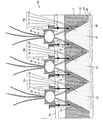
- the hydroponic cultivation apparatus (plant cultivation apparatus) 60 includes a plurality of root cutting mechanisms 10a, 10b, and 10c.
- the hydroponic cultivation apparatus 60 can grow a plurality of garlics 30.
- the hydroponic cultivation device 60 is different from the hydroponic cultivation device 1 in that a shelf plate 64 is provided instead of the shelf plate 4 and a culture solution tank 62 is provided instead of the culture solution tank 2.
- the culture medium tank 62 has a size that allows a plurality of root cutting mechanisms to be installed therein.
- three root cutting mechanisms 10 a, 10 b, and 10 c are installed in the culture medium tank 62.
- Each of the root cutting mechanisms 10a, 10b, and 10c includes a cutter 11, a blade 12, a stopper 13, a spring 14, and a cutoff table 45.
- Each of the root cutting mechanisms 10 a, 10 b, and 10 c is provided in the hydroponic cultivation device 60 corresponding to each of the plurality of garlics 30 cultivated by the hydroponic cultivation device 60.
- the shelf board 64 is configured to have such a size that the bulbs 31 of the plurality of garlics 30 can be placed in order to cultivate the plurality of garlics 30 by the hydroponic cultivation device 60.
- the shelf plate 64 has a plurality of openings 7 corresponding to the rooted portions of the bulbs 31 of the plurality of garlics 30 placed thereon. Furthermore, a plurality of openings for inserting the cutters 11 of the root cutting mechanisms 10 a, 10 b, and 10 c so as to surround the bulbs 31 of the plurality of garlics 30 placed on the shelf plate 64. 17 is provided. The cutters 11 of the root cutting mechanisms 10a, 10b, and 10c are inserted into the plurality of openings 17 formed in the shelf plate 64, respectively.
- the hydroponic cultivation apparatus 60 includes a plurality of root cutting mechanisms 10a, 10b, and 10c, and a common shelf board 64 on which the cutters 11 of the root cutting mechanisms 10a, 10b, and 10c are arranged. Has been.
- the hydroponic cultivation apparatus 60 since the plurality of garlics 30 can be cultivated with the single culture medium tank 62, plants can be cultivated efficiently at a reduced cost.
- the respective cutting bases 45 of the root cutting mechanisms 10a, 10b, and 10c are connected to each other in the vicinity of the lower surface by the connecting portion 65.
- a bubble generating tube (air stone) 66 larger than the bubble generating tube 46 is arranged inside the plurality of cutoff tables 45 and connection portions 65.
- the bubble generating tube 66 is arranged across the plurality of cutoff tables 45.
- the bubble generating tube 66 is connected to an air supply pump (not shown) provided outside the cutoff table 45 by a hollow tube 68.
- connection portion 65 is also formed with a plurality of openings 47 through which oxygen can pass. Thereby, the oxygen output from the bubble generating tube 66 can be effectively spread to the root 32 portions of the plurality of garlics 30.
- connection part 65 does not necessarily need to be provided, and the cutting tables 45 of the root cutting mechanisms 10a, 10b, and 10c may be separated from each other.
- Embodiment 5 A fifth embodiment of the root cutting mechanism of the present invention will be described.
- members having the same functions as those in the drawings explained in Embodiments 1 to 4 are given the same reference numerals and explanations thereof are omitted.
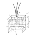
- FIG. 14 represent the structure of the hydroponic cultivation apparatus provided with the root cutting mechanism which concerns on 5th Embodiment, (a) is the hydroponic provided with the cutting stand whose cross section is trapezoid. It is a perspective view showing a cultivation apparatus, (b) is a top view of the hydroponic cultivation apparatus of (a).
- FIG. 15 is a perspective view showing a configuration of a hydroponic cultivation apparatus having a triangular cross section.
- the hydroponic cultivation apparatus 1 includes a root cutting mechanism 71.
- the root cutting mechanism 71 includes a cutting base 75 instead of the cutting base 15, and the arrangement of the cutter 72 is different from the root cutting mechanism 10.
- the root cutting mechanism 71 includes a cutter (movable part) 72, a blade 12, a stopper 13 (not shown in FIGS. 14A and 14B), and a spring 14 (FIGS. 14A and 14B). (Not shown) and a cutting stand 75.
- the cutter 72 includes a cutter group (first movable part group) 72A composed of a plurality of cutters 72a, 72b, 72c, and 72d arranged side by side, and a plurality of cutters 72e, 72f, 72g, and 72h arranged side by side. And a cutter group (second movable part group) 72B.
- the cutting table 75 includes a side surface (surface) that comes into contact with the blade 12 disposed on the cutter 72 when the cutter (movable part) 72 is pressed down to the lower limit.
- the distance between the side surfaces of the cutoff table 75 gradually increases from the top to the bottom. Therefore, when the cutter 72 is pressed, the blade 12 disposed on the cutter 72 can be brought into contact with the surface of the cutting table 75. Therefore, by pressing the cutter 72, the roots 32 of the garlic 30 can be harvested.
- the shape of the cutting stand 75 is a ridge shape raised in a streak shape.
- the cutting stand 75 extends in the longitudinal direction of the culture medium tank 2 and is formed in a streak shape.
- the cutting table 75 has a trapezoidal cross section in the short direction, which is a direction perpendicular to the longitudinal direction, which is a direction extending in a streak shape.
- the trapezoidal slope is the side surface.
- the cutting stand 75 is configured as a bowl shape as an example of the shape.
- the roots 32 of the garlic 30 placed on the shelf board 4 are arranged between the blade 12 and the side surface of the cutout table 75.
- the root 32 of the garlic 30 will extend along the side surface of the cutout 75.
- the root 32 of the garlic 30 is pressed against the side surface of the cutting table 75 and cut by the pressed cutters 72a to 72f among the plurality of cutters 72a to 72f.
- the garlic roots 32 can be reliably cut out, and the garlic 30 roots 32 can be efficiently harvested.
- the shelf plate 4 is provided with a plurality of openings 77 for inserting the cutters 72a to 72h.
- the cutters 72a to 72f are inserted into a plurality of openings 77 provided in the shelf board 4.
- Each of the cutters 72a, 72b, 72c, and 72d and each of the cutters 72e, 72f, 72g, and 72h are arranged side by side in the longitudinal direction of the shelf board 4.
- the cutter group 72 ⁇ / b> A and the cutter group 72 ⁇ / b> B are arranged so as to be separated so as to sandwich the garlic 30 supported by the shelf board 4. That is, each of the cutters 72a, 72b, 72c, and 72d and each of the cutters 72e, 72f, 72g, and 72h are disposed on the shelf plate 4 so as to face each other in the short direction of the shelf plate 4.
- the garlic 30 is arranged between the cutter group 72A and the cutter group 72B.
- the cutters 72a to 72f constituting each of the cutter group 72A and the cutter group 72B can be pressed independently.
- the root 32 of the garlic 30 can be cut out only by the blade 12 disposed at the tip of the pressed cutters 72a to 72f among the plurality of cutters 72a to 72f, the influence on the growth of the garlic 30 is affected.
- the roots 32 of garlic 30 can be harvested with inhibition.
- the number of cutters 72 arranged in the longitudinal direction of the shelf board 4 is not limited to four as in the present embodiment, and may be five or more, or may be three or less. Good.
- the cross section in the short direction of the cutting table may be a triangle instead of a trapezoid.
- the root cutting mechanism 76 includes a cutting table 78 instead of the cutting table 75.
- the shape of the cutting stand 78 is a ridge shape raised in a streak shape. That is, the cutting stand 78 extends in the longitudinal direction of the culture medium tank 2 and is formed in a streak shape.
- the shape of the cutting stand 78 has a triangular cross section in a direction orthogonal to the direction extending in the above-mentioned streak shape (that is, the extending direction).
- the triangular slope is a side surface for contacting the blade 12 of the cutter 72.
- the shape is made into a bowl shape so that a root cutting mechanism for cutting the roots 32 of a plurality of plants 5 is obtained.
- the configuration can be easily expanded. That is, when mounting and cultivating a plurality of plants 5 on the shelf board 4, it can be configured as the cutting tables 75 and 78 common to the plurality of plants 5. For this reason, when mounting the some plant 5 on the shelf board 4, the space
- the cutter 72 includes a cutter group 72A and a cutter group 72B. For this reason, similarly, it becomes easy to expand the device configuration to a root cutting mechanism for cutting the roots 32 of the plurality of plants 5. That is, when placing and cultivating a plurality of plants 5 on the shelf board 4, a cutter group 72 ⁇ / b> A composed of a plurality of cutters 72 arranged side by side in common with the plurality of plants 5 and a cutter group 72 ⁇ / b> B are configured. can do. For this reason, when mounting the some plant 5 on the shelf board 4, the space
- the root cutting mechanism of the present invention can be attached to a plant cultivation apparatus for cultivating a plant, and is a root cutting mechanism for cutting the root of the plant.
- a movable part arranged to be pressed, and a cutting part arranged at the tip of the movable part and cutting the root of the plant leaving a part by pressing the movable part. It is characterized by having.
- the movable part having the cutting part at the tip is arranged on the support base so that it can be pressed. Thereby, the root of the plant which a support stand supports can be cut out by pushing down the above-mentioned movable part.
- the cutting unit cuts off the root of the plant leaving a part of the root of the plant when the movable unit is pressed.
- the root of the plant can be harvested by suppressing the influence on the growth of the plant by cutting off the root of the plant without cutting all the roots of the plant and leaving a part of the roots. .
- a plurality of the movable parts are arranged, and the plurality of movable parts are arranged so as to surround a plant supported by the support base and can be pressed independently.
- the root of the plant is cut only by the cut part arranged at the tip of the pressed movable part, and depending on the cut part arranged in the movable part that is not pressed.
- the roots of the plants are not cut off. That is, the roots of the plant are harvested only by the cut-out portion arranged in the pressed movable portion, and other portions are left.
- the root of the plant can be harvested while suppressing the influence on the growth of the plant.
- the movable part is arranged so as to surround a part of the plant supported by the support base. According to the above configuration, only a part of the roots of the plant supported by the support base can be cut out by the cutout part when the movable part is pressed down, and other parts can be left.
- the root of the plant can be harvested while suppressing the influence on the growth of the plant.
- the support base is provided with a plurality of openings for inserting the plurality of movable parts arranged around the plant supported by the support base, and the movable part includes the plurality of movable parts. It is preferable to be inserted into at least one of the openings.
- the movable part can be arranged so as to surround at least a part of the plant supported by the support base. For this reason, only a part of the root of the plant can be cut out by pressing the movable part.
- a cutting stand including a surface that comes into contact with the cutting portion arranged in the movable portion when the movable portion is pressed down to the lower limit is provided.
- the root of the placed plant when a plant is placed on the support stand, the root of the placed plant is arranged between the cut portion and the surface of the cut stand. And the root of the said plant is pressed and cut
- the distance between the surfaces of the cutoff table gradually increases from the upper side to the lower side.
- the shape of the cutoff table is a cone or a truncated cone, and the surface is a side surface of the cone or the truncated cone.
- the shape of the said cutting stand is a polygonal pyramid or a polygonal frustum, and the said surface is the side surface of the said polygonal pyramid or a polygonal frustum.
- the plant roots extend along the surface. Therefore, since the root of the plant can exist on the locus of the cut portion that moves when the movable portion is pressed, the root of the plant can be cut more reliably by the cut portion. it can.
- the shape of the cutting stand is a cone or a truncated cone, and when changing the amount or position of cutting the root of the plant, the size or number of the cutting portions may be changed. There is no need to change. For this reason, the increase in cost can be suppressed and the balance between the suppression of the influence on the growth of the plant and the harvest amount of the root of the plant can be easily taken.
- the shape of the above-mentioned cutting table is preferably a ridge shape that rises in a streak shape.
- the cutting table can be configured by forming a bowl shape.
- the root of the plant mounted in the said support stand will be distribute
- the device configuration can be easily expanded to a root cutting mechanism for cutting a plurality of plant roots. That is, when mounting and cultivating a plurality of plants on a support base, it can be configured as a cutout base common to the plurality of plants. For this reason, when mounting a some plant on a support stand, the space
- the shape of the cutting table is a trapezoidal cross section in a direction perpendicular to the direction extending in the streak shape.
- the cross section of the direction orthogonal to the direction extended in the said stripe form is a triangle.
- the root of the plant extends along the surface, so that the root of the plant can be more reliably cut out by the cut-out portion.
- the movable part is composed of a first and second movable part group composed of a plurality of movable parts arranged side by side, and the first movable part group and the second movable part group include the above
- the movable parts are arranged so as to be able to sandwich the plant supported by the support base, and the movable parts constituting each of the first and second movable part groups are independently pressed down. It is preferable that it is possible.
- the root of the plant can be cut out only by the cutout portion arranged at the tip of the pressed movable portion among the plurality of movable portions, so that the influence on the growth of the plant is suppressed.
- the root of the plant can be harvested.
- the movable part is composed of first and second movable part groups composed of a plurality of movable parts arranged side by side
- the device configuration can be easily expanded to a root cutting mechanism for cutting the roots of a plurality of plants.
- the first and second movable unit groups including a plurality of movable units arranged side by side in common with the plurality of plants may be configured. it can. For this reason, when mounting a some plant on a support stand, the space
- a bubble generating tube disposed inside the cutoff table is provided, and a plurality of openings through which the gas output from the bubble generating tube is passed are provided on the surface of the cutoff table.
- the plurality of movable parts are preferably arranged so as to surround a plant supported by the support base so as to have a circular shape.
- the said several movable part when the said several movable part is planarly viewed, it is preferable that the said several movable part surrounds the circumference
- the plurality of movable parts can be arranged around the plant supported by the support table in accordance with the shape of the cutoff table. Thereby, the root of the plant can be surely cut by pressing each of the plurality of movable parts.
- the support base is provided with a connecting member that connects the movable portion so that the movable portion can be pressed, and the movable portion includes a portion connected by the connecting member and the cutout portion. It is preferable to have a bent portion bent between the portion where it is disposed.
- the relative position between the cut portion disposed on the movable portion and the surface of the cut stand on which the cut portion abuts when the movable portion is pressed down by adjusting the shape of the bent portion. Can be changed. For this reason, since the position which cuts the root of the said plant can be adjusted, the convenience can be improved.
- the plant is preferably garlic. According to the said structure, the influence which it has on the growth of a garlic can be suppressed, and a garlic root can be harvested efficiently.
- the plant cultivation apparatus of the present invention includes the above root cutting mechanism.
- the influence which it has on the growth of the plant cultivated with the said plant cultivation apparatus can be suppressed, and the root of the said plant can be harvested efficiently.
- a plurality of the root cutting mechanisms are provided, and a support base on which movable parts of the plurality of root cutting mechanisms are arranged is configured in common.
- the hydroponic cultivation apparatus of the present invention is the plant cultivation apparatus that cultivates the plant by hydroponic cultivation.
- the influence which it has on the growth of the plant cultivated with the said hydroponics apparatus can be suppressed, and the root of the said plant can be harvested efficiently.
- the present invention can be applied to an apparatus for artificially cultivating a plant and an apparatus for harvesting the roots of a plant cultivated by the apparatus.
Landscapes
- Life Sciences & Earth Sciences (AREA)
- Environmental Sciences (AREA)
- Hydroponics (AREA)
- Cultivation Of Plants (AREA)
Abstract
根切り機構(10)は、ニンニク(30)の栽培を行なう水耕栽培装置(1)に取り付け可能であり、ニンニク(30)の根(32)を切るためのものであり、ニンニク(30)の鱗茎(31)を支持する棚板(4)に、押下されることが可能に配されたカッター(11)と、カッター(11)の先端に配され、カッター(11)が押下されることで、一部を残してニンニク(30)の根(32)を切り取る刃(12)とを備えている。これにより、植物栽培装置で栽培されている植物の生育に及ぼす影響を抑制し、かつ、効率よく上記植物の根を収穫する。
Description
本発明は、人工的に植物を栽培する装置、及び当該栽培されている植物の根を切る根切機構に関する。
近年、植物を人工的に植物工場で栽培する技術が開発されている。現在のところ、植物工場で栽培される植物としては、葉菜類の栽培がほとんどである。このような葉菜類の植物は、その葉や実などが収穫され、根は利用されず捨てられる場合が多い。今後、植物工場で栽培可能な品種が広がることが期待されている。
ここで、植物工場では、コスト効率が最大の課題となるため、栽培する植物としては、残渣の少ない作物(根なども全て利用できるもの)が求められている。
一例として、ニンニクは、一般的には、鱗茎を食用として収穫することが多いが、その茎や葉の部分も野菜として利用されている。
また、特に、ニンニクは、根の部分にも様々な医療用途に適用が可能といわれるアホエンが豊富に含まれている。このように、ニンニクは、残渣の少ない作物である。
特許文献1には、水耕栽培システムにより、ニンニクの根を効率よく栽培する栽培方法が提案されている。
また、特許文献2には、植物の根を収穫するための根切り装置が提案されている。特許文献2には、発芽した植物が通過できる網目を持つネット枠と,ネット枠の上面または下面、若しくは複数ネット枠の間にカッターが通過することによって、ネットより下の部分を切断する根きり装置が開示されている。
ニンニク等、植物の根は、一度切り取っても再生する。このため、水耕栽培で、植物の根を、効率よく収穫するために、植物の根の部分を繰り返し収穫するような装置が必要である。
特許文献1に記載の水耕栽培システムには、水耕栽培を行なっているニンニクの根を収穫するための構成が備えられていない。このため、特許文献1に記載の水耕栽培システムでは、ニンニクの根を収穫する場合、水耕栽培システムから、水耕栽培を行なっているニンニクを取り外してから、当該ニンニクの根を収穫する必要がある。このように、特許文献1の記載の水耕栽培システムでは、根を収穫するための効率が悪いという課題が生じる。
また、特許文献2に記載の根きり装置は、根を利用することを前提としておらず、根切り後に栽培を続けるような栽培方法が考慮されていない。このため、特許文献2に記載の根きり装置では、植物体の根を全て切り取ってしまうため、根切り後の植物の生育に大きなダメージを与えてしまうことになる。
本発明は、上記の問題点を解決するためになされたもので、その目的は、植物栽培装置で栽培されている植物の生育に及ぼす影響を抑制し、かつ、効率よく上記植物の根を収穫する。
上記の課題を解決するために、本発明の根切り機構は、植物の栽培を行なう植物栽培装置に取り付け可能であり、当該植物の根を切るための根切り機構であって、上記植物を支持する支持台に、押下されることが可能に配された可動部と、上記可動部の先端に配され、当該可動部が押下されることで、一部を残して上記植物の根を切り取る切取部とを備えていることを特徴としている。
上記構成によると、先端に切取部が配された可動部は、押下されることが可能に支持台に配されている。これにより、上記可動部を押下することで、支持台が支持する植物の根を切り取ることができる。
このため、上記支持台が支持する植物の根を切り取るために、当該植物を支持台から取り出す必要は無く、上記支持台に植物を載置したまま当該植物の根を切り取ることができるので、効率よく、植物の根を収穫することができる。
上記構成によると、上記切取部は、上記可動部が押下されることで、上記植物の根の一部を残して、当該植物の根を切り取る。このように、上記植物の根を全て切り取らず、一部を残して、上記植物の根を切り取ることで、上記植物の生育に及ぼす影響を抑制して、上記植物の根を収穫することができる。
このように、上記構成によると、植物栽培装置で栽培されている植物の生育に及ぼす影響を抑制し、かつ、効率よく上記植物の根を収穫することができる。
本発明は、植物の栽培を行なう植物栽培装置に取り付け可能であり、当該植物の根を切るための根切り機構で、上記植物を支持する支持台に、押下されることが可能に配された可動部と、上記可動部の先端に配され、当該可動部が押下されることで、一部を残して上記植物の根を切り取る切取部とを備えている。
これにより、植物栽培装置で栽培されている植物の生育に及ぼす影響を抑制し、かつ、効率よく上記植物の根を収穫することができるという効果を奏する。
〔実施の形態1〕
(根切り機構を備えた水耕栽培装置の構成)
以下、本発明の根切り機構の第1の実施形態について説明する。
(根切り機構を備えた水耕栽培装置の構成)
以下、本発明の根切り機構の第1の実施形態について説明する。
図1の(a)は、本実施の形態に係る水耕栽培装置1の構成を表す断面図であり、(b)は(a)の平面図である。
水耕栽培装置(植物栽培装置)1は、水耕栽培によって、植物の栽培を行なう植物栽培装置である。本実施の形態では、ニンニク(植物)30を栽培しているものとして説明する。水耕栽培装置1は、培養液タンク2と、培養液3と、棚板(支持台)4と、根切り機構10とを主に備えている。
根切り機構10は、植物の栽培を行なう水耕栽培装置1に取り付け可能であり、水耕栽培装置1で栽培している植物の根を切るためのものである。根切り機構10は、水耕栽培装置1が栽培している植物の根を全て切り取らず、一部を残すようにして当該植物の根を切り取る。
根切り機構10は、棚板4に、押下されることが可能に配されたカッター(可動部)11と、カッター11の先端に配され、カッター11が押下されることで一部を残してニンニク30の根32を切り取るための刃(切取部)12と、棚板4に配され、カッター11を押下されることが可能に棚板4と接続するストッパー(接続部材)13と、弾性部材であるバネ14と、カッター11を下限まで押下したとき刃17と当接する表面を含む切取台15とを備えている。換言すると、棚板4に対するカッター11の相対位置のうち、刃17が切取台15の表面と当接する位置が、カッター11の下限である。
培養液タンク2は、培養液3を収容するための水槽である。培養液タンク2の材質は特に限定されず、プラスチック、コンクリート等などからなる。培養液3は、栽培する植物に応じて必要な養分が加えられた液体の肥料であり、一般的に使用されている液体肥料を用いることができる。
棚板4は、水耕栽培装置1で栽培する植物を支持し、また、後述するように、押下されることが可能に配されたカッター11を支持する支持台でもある。ニンニク30は、この棚板4に載置されて栽培されている。
棚板4の材質は、栽培する植物を安定して載置することができ、また、カッター11を押下することができるように接続することができるものであればよく、発砲スチロール等からなる。
なお、棚板4の材質としては、上述したように、発泡スチロールのように軽量な材質が好ましい。特に、棚板4は、高圧縮で強度を高めた発泡スチロールで構成されていることが好ましい。これにより、棚板4の強度を高めることができるので、カッター4を押下する力が加わっても破損することを防止することができる。
棚板4には、載置されているニンニク30の鱗茎(植物)31を支持することができ、ニンニク30の根32を通過させることができる程度の大きさの開口部7が設けられている。棚板4に設けられる開口部7は、栽培する植物に応じて大きさが決定されるものである。本実施の形態のように、ニンニク30を栽培する場合、開口部7の直径は、例えば、1~5cm程度が適当である。
棚板4は、培養液3の液面と、ニンニク30の根32の生え際との間に、空間が設けられる程度の高さに設置されている。このようにニンニク30の根32の生え際に空間を設けることで、ニンニク30の根32の生え際のうち、空気に露出されている部分が酸素を吸収し易くなる。これにより、ニンニク30の成長を促進することができる。
また、棚板4には、カッター11を挿設するための複数の開口部17が設けられている。開口部17は、刃12の形状に対応するような形状となるように棚板4に設けられている。後述するように、本実施の形態では、カッター11は複数設けられているので、複数のカッター11に対応して、開口部17も棚板に複数設けられている。
また、棚板4に、ニンニク30の鱗茎31をそのまま載置することで、ニンニク30を発根させてもよいが、水耕栽培装置1では、棚板4に載置したニンニク30の鱗茎31を、フィルム5、及びビーズ6からなる保護部材で、発根部分が露出するように覆っている。これにより、ニンニク30の鱗茎31の乾燥を防ぐことができる。フィルム5は、例えば、合成樹脂等からなり、ビーズ6は、例えば、発泡スチロール等からなる。
また、棚板4に、栽培する植物の根が通過する程度の開口部を設けた培地を設け、当該培地に、上記栽培する植物を載置するようにしてもよい。
カッター11は、棚板4を貫通して配されるものであり、水耕栽培装置1で栽培される植物のうち、棚板4より下の部分を切り取るためのものである。
カッター11は、複数のカッター11a・11b・11c・11dからなる。複数のカッター11a・11b・11c・11dは、棚板4が支持するニンニク30の鱗茎31の周囲を囲って配されており、それぞれ独立して、押下されることが可能である。
カッター11a・11b・11c・11dを平面視したとき、カッター11a・11b・11c・11dは、円形状となるように、棚板4が支持するニンニク30の鱗茎31の周囲を囲って配されている。水耕栽培装置1では、ニンニク30の鱗茎31を覆うフィルム5の外側の周囲を囲って、カッター11a・11b・11c・11dが配されている。
カッター11a・11b・11c・11dは、平面視したとき、円形状を4分割した形状として構成されている。
棚板4には、棚板4が支持するニンニク30の鱗茎31の周囲を囲って配するカッター11a・11b・11c・11dをそれぞれ挿設するための開口部17として、複数の開口部17a・17b・17c・17dが設けられている。そして、カッター11a・11b・11c・11dのそれぞれは、開口部17a・17b・17c・17dのそれぞれに挿設されている。つまり、開口部17a・17b・17c・17dも、4分割された円形状となるように、平面視したときにニンニク30の鱗茎31の周囲を囲って、棚板4に設けられている。
図2を用いて、棚板4に接続されたカッター11の構成について説明する。図2は、水耕栽培装置1のカッター11の構成を説明する図である。なお、カッター11a・11b・11c・11dは、いずれも同様の構成であるので、図2では、カッター11aの構成について説明する。
カッター11aは、棚板4に設けられた開口部17aを貫通するように配されており、カッター11aの一方の端部(押下部)は、棚板4の表面(ニンニク30の鱗茎31が載置されている側の面)と、弾性部材であるバネ14によって接続されている。
カッター11aは、棚板4の裏面(培養液3と対向する側の面)と、ストッパー13によって接続されている。このように、カッター11aにバネ14と、ストッパー13を設けることで操作性を向上させることができる。
カッター11aの他方の端部(先端部)には、カッター11aが押下されることで、一部を残してニンニク30の根32を切り取る刃12が配されている。
このように、カッター11a・11b・11c・11dは、それぞれ独立して、押下されることが可能に棚板4に配されている。このため、ニンニク30の根32のうち、切断したい箇所に対応するカッターを押下することが可能である。
また、図1の(a)に示すように、切取台15は、ニンニク30の下方に位置するように、培養液タンク2内に設置されている。
切取台15の材質は、例えば、ポリプロピレンなどのプラスチック等を用いることができる。
切取台15は、カッター11a・11b・11c・11dを、下限まで押下したとき、カッター11a・11b・11c・11dに配された刃12と当接する表面を含むものである。
切取台15は、上方から下方にかけて、上記表面間の距離が、次第に広がっている。これにより、カッター11a・11b・11c・11dを押下したとき、当該カッター(例えばカッター11a)に配された刃12を、切取台15の表面に当接させることができる。従って、カッター11a・11b・11c・11dを押下することで、ニンニク30の根32を収穫することができる。具体的には、本実施の形態では、切取台15の形状は円錐台であり、その側面が、上記表面である。
(根切りについて)
次に、図3、4を用いて、根を切り取ることについて説明する。
次に、図3、4を用いて、根を切り取ることについて説明する。
図3は、水耕栽培装置1で栽培している植物の根を収穫することを説明する図である。
なお、図3を用いて、カッター11a・11b・11c・11dのうち、カッター11aを押下する場合について説明する。
切取台15は、その側面が、カッター11aを下限まで押下したとき、カッター11aに配された刃12と当接するように配されている。刃12の刃先は、切取台15の側面と適合するように形成されている。
円錐台である切取台15は、ニンニク30の下方に位置するように、培養液タンク2内に設置されている。
このため、ニンニク30が棚板4に載置されると、ニンニク30の根32は、生育に伴って、切取台15の側面に沿って伸びることになる。このように、ニンニク30の根32が、切取台15の側面に沿って伸びるので、ニンニク30の根32が、刃12と、切取台15の側面との間に配されることになる。そして、図3の矢印に示すように、ニンニク30の根32のうち、収穫したい箇所に該当するカッター11aを押下する。
図4は、複数のカッター11のうち、一部が押下された水耕栽培装置1を表す断面図である。
図4の水耕栽培装置では、カッター11aが押下されている。カッター11cは押下されていない。図4に示すように、カッター11a・11b・11c・11dのうち、押下されたカッター11aに配された刃12によって、ニンニク30の根32は、切取台15の側面に押圧されて切断される。
上述した特許文献2の根切り装置では、植物の根を横方向に切断する構成なので、当該植物の根は全て切断されることになる。一方、本実施の形態に係る根切り機構10によると、カッター11を横方向(水平方向)でははく、縦方向(鉛直方向)に押入れる構成であるので、ニンニク30の根32を全て切り取らず、部分的に残すことが可能となる。
このように、根切り機構10の複数のカッター11a・11b・11c・11dは、棚板4が支持するニンニク30の周囲を囲って配されており、それぞれ独立して、押下されることが可能である。このため、カッター11a・11b・11c・11dのうち、押下されたカッター11aの先端に配されている刃12によってだけニンニク30の根32を切り取り、押下されていないカッター11b・11c・11dに配されている刃12によっては、ニンニク30の根32は切り取られない。すなわち、ニンニク30の根32は、押下されたカッター11aに配された刃12によってだけ収穫され、その他の部分は残される。
従って、根切り機構10によると、ニンニク30の生育に及ぼす影響を抑制して、ニンニク30の根32を収穫することができる。
また、根切り機構10では、カッター11aを、下限まで押下したとき、カッター11aに配された刃12と当接する側面を含む切取台15を備えているので、ニンニク30の根32を確実に切り取ることができ、効率よく、ニンニク30の根32を収穫することができる。
また、図1の(b)に示したように、水耕耕栽培装置1では、カッター11a・11b・11c・11dを平面視したとき、カッター11a・11b・11c・11dは、円形状となるように、棚板4が支持するニンニク30の鱗茎31の周囲を囲って配されている。
このように、円錐台形である切取台15の形状に合せて、カッター11a・11b・11c・11dを、ニンニク30の鱗茎31の周囲を囲って配することで、カッター11a・11b・11c・11dの何れを押下しても、刃12と切取台15の側面とを当接させることができ、確実に、ニンニク30の根32を切り取ることができる。
(切取台の形状とカッターの配置)
切取台15は、下記の理由から錐形であることが好ましい。
切取台15は、下記の理由から錐形であることが好ましい。
まず、切取台15の形状が、錐形でない場合について図5の(a)(b)を用いて説明する。
図5の(a)(b)は、断面形状が長方形である切取台を備えた水耕栽培装置を表す図であり、(a)は、側面が、押下された刃と当接しない切取台を備えた水耕栽培装置を表す図であり、(b)は、側面が、押下された刃と当接する切取台を備えた水耕栽培装置を表す図である。
図5の(a)の切取台115は、断面が長方形である。換言すると、切取台115の形状は柱状となっている。
また、切取台115は、カッター11が押下されたとしても、カッター11の先端に配された刃12と、切取台115の側面とが当接しないような円形状となっている。換言すると、平面視したとき、切取台115の上面および下面のそれぞれの面積は、カッター11a・11b・11c・11dによって構成される円の面積より小さい。
このため、切取台115の側面に沿って伸びたニンニク30の根32を切断しようと、カッター11を押下したとしても、当該カッター11に配された刃12と、切取台115の側面とによって、ニンニク30の根32を押圧することができず、ほとんどニンニク30の根32を切断することができない。
また、図5の(b)の切取台125は、断面が長方形である。換言すると、切取台125の形状は柱状となっている。
また、切取台125は、カッター11が押下されると、カッター11の先端に配された刃12と、切取台125の側面とが当接するような円形状となっている。換言すると、平面視したとき、切取台115の上面および下面の面積は、カッター11a・11b・11c・11dによって構成される円の面積より大きい。
このため、ニンニク30の根32は、水平方向に配された切取台125の上面上で入り組んで伸びることになる。このため、押下されたカッター11の刃12によって切断されるニンニク30の根32は、切り取り位置や長さがばらばらとなり、商品としての価値を低下させることになる。
また、ニンニク30の根32は、切取台125の上面上で入り組んで伸びるので、カッター11のうち、例えばカッター11aなど、必ずしも、押下したカッター11aの刃12の下方に存在しているとは限らない。このため、収穫の効率が低下することになる。
一方、図1の(a)(b)、図3で説明したように、根切り機構10が備える切取台15は、錐台形状をしている。
具体的には、平面視したとき、切取台15の上面の面積は、カッター11a・11b・11c・11dによって構成される円の面積より小さく、切取台15の下面の面積は、カッター11a・11b・11c・11dによって構成される円の面積より大きい。
また、平面視したときに、カッター11a・11b・11c・11dが円形状に配されていることに合せて、切取台15は、円錐台形状をしている。
これにより、切取台15は、カッター11を、下限まで押下したとき、カッター11に配された刃12と当接するように側面が構成されている。
このため、切取台15の側面に沿って伸びたニンニク30の根32を、押下されたカッター11aに配された刃12によって切断することができるので、長さを揃えてニンニク30の根32を切断することができ、商品としての価値を低下させることなく、より確実に、ニンニク30の根32を収穫することができる。
ここで、切取台15は、錐形であればよく、円錐台形状に限らず、円錐形であってもよい。さらに、図6の(a)~(c)に示すように、切取台15は、多角錐台であってもよい。
図6の(a)~(c)は、根切り機構を備える水耕栽培装置を表す平面図であり、(a)は三角錐台の切取台を備える水耕栽培装置を表し、(b)は四角錐台の切取台を備える水耕栽培装置を表し、(c)は五角錐台の切取台を備える水耕栽培装置を表す図である。
図6の(a)に示すように、切取台22は、三角錐台の形状を有している。また、カッター21は、複数のカッター21a・21b・21cからなり、平面視したとき、三角形となるように、棚板4に挿設されている。
このように、切取台22は、カッター21を、下限まで押下したとき、カッター21に配された刃12と当接するように側面が構成されている。
図6の(b)に示すように、切取台24は、四角錐台の形状を有している。また、カッター23は、複数のカッター23a・23b・23c・23dからなり、平面視したとき、四角形となるように、棚板4に挿設されている。
このように、切取台24は、カッター23を、下限まで押下したとき、カッター23に配された刃12と当接するように側面が構成されている。
図6の(c)に示すように、切取台26は、五角錐台の形状を有している。また、カッター25は、複数のカッター25a・25b・25c・25d・25eからなり、平面視したとき、五角形となるように、棚板4に挿設されている。
このように、切取台26は、カッター25を、下限まで押下したとき、カッター25に配された刃12と当接するように側面が構成されている。
さらに、切取台22、切取台24、切取台26は、それぞれ、三角錐、四角錐、五角錐であってもよいし、六角錐又は六角錐台以上の多角錐、多角錐台であってもよい。
このように、カッター21a・21b・21c、22a・22b・22c、23a・23b・23cそれぞれを平面視したとき、カッター21a・21b・21c、22a・22b・22c、23a・23b・23cは、多角形状となるように、棚板4が支持するニンニク30の鱗茎31の周囲を囲って配されている。
これにより、切取台22、切取台24、切取台26のそれぞれの形状に合せて、カッター21a・21b・21c、22a・22b・22c、23a・23b・23cを、棚板4が支持するニンニク30の鱗茎31を囲って配することができる。これにより、カッター21a・21b・21c、22a・22b・22c、23a・23b・23cのそれぞれを押下することで、確実に、ニンニク30の根32を切り取ることができる。
しかし、例えば図6の(a)に示す切取台22のように多角錐台とすると、カッター21の分割数や、ニンニク30の根32を切り取る位置を変更する場合、切取台22の形状もそれに合せて変更する必要がある。
一方、切取台15の形状を円錐台又は円錐とすることで、ニンニク30の根32を切り取る量や位置を変更する場合、カッター11a・11b・11c・11dのそれぞれの大きさ、すなわち、カッター11a・11b・11c・11dのそれぞれに配された刃12の大きさや、個数を変更すればよく、切取台15の形状を変更する必要が無い。
図7の(a)(b)は、円形に配された複数のカッターを備える水耕栽培装置を表す平面図であり、(a)は2分割されたカッターを備える水耕栽培装置を表し、(b)は3分割された水耕栽培装置を表す図である。
図7の(a)では、カッター27は、2分割されたカッター27a・27bからなり、平面視したとき、円形状となるように、棚板4に挿設されている。このように、切取台15は、カッター27を、下限まで押下したとき、カッター27に配された刃12と当接するように側面が構成されている。
図7の(b)では、カッター28は、3分割されたカッター28a・28b・28cからなり、平面視したとき、円形状となるように、棚板4に挿設されている。このように、切取台15は、カッター27を、下限まで押下したとき、カッター27に配された刃12と当接するように側面が構成されている。
このように、切取台15のように、円錐台又は円錐形とすることで、切取台15の形状を変更することなく、カッター27・28のように、分割数や大きさを変更することで、ニンニク30の根32を切り取る量や位置を変更することができる。
このため、切取台15のように、円錐台、又は円錐形状とすることで、コスト増加を抑え、ニンニク30の生育に及ぼす影響の抑制と、ニンニク30の根32の収穫量とのバランスを、容易に取ることができる。
また、カッター11a・11b・11c・11dは、図1の(a)(b)で示したように棚板4が支持するニンニク30の鱗茎31の周囲を1周分囲む必要はなく、ニンニク30の鱗茎31の一部を囲って配されていればよい。また、カッター11a・11b・11c・11dは、常時、開口部17a・17b・17c・17dのそれぞれに挿入されている必要はない。
すなわち、図8に示すように、カッター11a・11b・11c・11dのうち、ニンニク30の根32を切り取る際に、例えば、カッター11aなど、必要なカッターを、対応する開口部17aに挿設するようにしてもよい。
図8は、複数設けられた開口部の何れかにカッターを挿入する様子を表す図である。
このように、水耕栽培装置1の棚板4には、棚板4が支持するニンニク30の鱗茎31の周囲を囲って配する複数のカッター11a・11b・11c・11dを挿設するための複数の開口部17a・17b・17c・17dが設けられており、カッター11a・11b・11c・11dのうち少なくとも何れかが(例えばカッター11a)、開口部17a・17b・17c・17dのうちの何れか(例えば開口部17a)に挿設されていればよい。
これにより、棚板4が支持するニンニク30の鱗茎31の一部を囲って、カッター11aを配することができる。
このように、ニンニク30の鱗茎31の一部だけを囲むカッター11aが押下されることで、カッター11aに配された刃12により、ニンニク30の根32の一部だけを切り取ることができ、その他の部分を残すことができる。
このため、ニンニク30の生育に及ぼす影響を抑制して、ニンニク30の根32を収穫することができる。また、上記植物の生育に及ぼす影響の抑制と、上記植物の根の収穫量とのバランスを、容易に取ることができる。
また、開口部17a・17b・17c・17dのように、円形状を4等分など等分割された開口部を棚板4に設けた場合、それに挿設されるカッター11a・11b・11c・11dは、4つ用意する必要はなく、カッター11aだけ等、等分割されたうちの1つだけ用意すればよい。これにより、カッター11を製造するコストを低下させることができる。
(まとめ)
このように、植物の根を切るためのものであり、植物の栽培を行なう植物栽培装置に取り付け可能な根切り機構10は、水耕栽培装置1に取り付けられている。そして、根切り機構10は、ニンニク30を支持する棚板4に、押下されることが可能に配されたカッター11a・11b・11c・11dと、カッター11a・11b・11c・11dのそれぞれの先端に配され、カッター11a・11b・11c・11dが押下されることで、一部を残してニンニク30の根32を切り取る刃12とを備えている。
このように、植物の根を切るためのものであり、植物の栽培を行なう植物栽培装置に取り付け可能な根切り機構10は、水耕栽培装置1に取り付けられている。そして、根切り機構10は、ニンニク30を支持する棚板4に、押下されることが可能に配されたカッター11a・11b・11c・11dと、カッター11a・11b・11c・11dのそれぞれの先端に配され、カッター11a・11b・11c・11dが押下されることで、一部を残してニンニク30の根32を切り取る刃12とを備えている。
このように、先端に刃17が配されたカッター11a・11b・11c・11dは、押下されることが可能に棚板4に配されている。これにより、カッター11a・11b・11c・11dを押下することで、棚板4が支持するニンニク30の根32を切り取ることができる。
このため、棚板4が支持するニンニク30の根32を切り取るために、ニンニク30を棚板4から取り出す必要は無く、棚板4にニンニク30を載置したままニンニク30の根32を切り取ることができるので、効率よく、ニンニク30の根32を収穫することができる。
また、栽培しているニンニク30の根32を一度に全て切り取ると、新しい根32が生えるまでニンニク30は、水や養分を吸収できなくなり、ニンニク30が弱ったり枯れたりしてしまう場合がある。
一方、上記構成によると、刃17は、カッター11a・11b・11c・11dの何れかが押下されることで、ニンニク30の根32の一部を残して、ニンニク30の根32を切り取る。このように、ニンニク30の根32を全て切り取らず、一部を残して、ニンニク30の根32を切り取ることで、ニンニク30の生育に及ぼす影響を抑制して、ニンニク30の根32を収穫することができる。
このように、水耕栽培装置1は、根切り機構10を備えているので、水耕栽培装置1で栽培されているニンニク30の生育に及ぼす影響を抑制し、かつ、効率よくニンニク30の根32を収穫することができる。
また、本実施の形態では、水耕栽培装置1が栽培する植物は、ニンニク30であるものとして説明した。しかし、根きり機構10を取り付ける水耕栽培装置1が栽培する植物は、根を収穫することが必要な植物であればよく、例えば、ニンニク以外にも、漢方薬や生薬として根の部分を利用する植物などをあげることができる。
さらに、本実施の形態の根切り機構10は、植物を栽培する装置に取り付けられればよく、例えば水耕栽培装置1以外にも、根にミスト状の培養液をスプレーして栽培する噴霧耕等の装置に取り付けてもよい。
〔実施の形態2〕
本発明の根切り機構の第2の実施の形態について説明する。なお、説明の便宜上、実施の形態1にて説明した図面と同じ機能を有する部材については、同じ符号を付記し、その説明を省略する。
本発明の根切り機構の第2の実施の形態について説明する。なお、説明の便宜上、実施の形態1にて説明した図面と同じ機能を有する部材については、同じ符号を付記し、その説明を省略する。
図9は、第2の実施の形態に係る根切り機構を備えた水耕栽培装置の構成を表す断面図である。
図9に示すように、水耕栽培装置1は、根切り機構41を備えている。根切り機構41は、切取台15に替えて、切取台45を備え、さらに、気泡発生管(エアーストーン)46を備えている点で、根切り機構10と相違する。
根切り機構41は、カッター11と、刃12と、ストッパー13と、バネ14と、切取台45と、気泡発生管46とを備えている。
気泡発生管46は、培養液3に、酸素(気体)を供給するためのエアーストーンであり、酸素を多数の気泡として出力する。気泡発生管46は、切取台45の外部に設けられた送気ポンプ(不図示)と、中空チューブ48で繋がれている。
なお、気泡発生管46は、培養液3に酸素を出力することができればよく、空気等の酸素が含まれた気体を気泡として出力してもよい。
切取台45は、切取台15と同様に、ニンニク30の下方に位置するように、培養液タンク2内に設置されている。切取台45は、内部に、気泡発生管46が配されている。そして、切取台45の側面(表面)には、気泡発生管46から出力される酸素を通す複数の開口部47が設けられている。なお、切取台45の形状や材質等は切取台15と同様である。
ここで、水耕栽培では、培養液中の酸素濃度を高くすると、栽培している植物の根が良く成長することが知られている。
そこで、根切り機構41のように、切取台45の内側に気泡発生管46を設置した場合でも、切取台45に酸素が通過できる複数の開口部47を形成することで、ニンニク30の根32の部分に効果的に酸素を行き渡らせることが可能となる。根切り機構41によると、切取台45を配した水耕栽培装置1で栽培されているニンニク30の根32に、効果的に酸素を供給することができる。
また、切取台45は、上述したように、円錐や円錐台等の錐形状である。このため、切取台45の内部の空間が大きい下面近傍に気泡発生管46を配置することで、多くの気泡を発生させるために、比較的、設置面積の大きな気泡発生管46を、切取台45の内部に設置することができる。加えて、切取台45の側面は傾斜しているので、柱状形状など側面が垂直である場合と比べて、広範囲に、効率よく、気泡発生管46から出力される酸素の気泡を、培養液中に分散させることができる。このように、切取台45は、錐形状なので、効率よく、培養液3中に、酸素を供給することができる。
〔実施の形態3〕
本発明の根切り機構の第3の実施の形態について説明する。なお、説明の便宜上、実施の形態1、2にて説明した図面と同じ機能を有する部材については、同じ符号を付記し、その説明を省略する。
本発明の根切り機構の第3の実施の形態について説明する。なお、説明の便宜上、実施の形態1、2にて説明した図面と同じ機能を有する部材については、同じ符号を付記し、その説明を省略する。
図10は、第3の実施の形態に係る根切り機構を備えた水耕栽培装置の構成を表す断面図である。
図10に示すように、水耕栽培装置1は、根切り機構51を備えている。根切り機構51は、カッター11に替えてカッター52を備え、また、切取台15に替えて切取台55を備えている点で、根切り機構10と相違する。
根切り機構41は、カッター52と、刃12と、ストッパー13と、バネ14と、切取台55とを備えている。
カッター52は、ストッパー13によって棚板4に接続されている箇所、すなわち、カッター52のうち、ストッパー13が配されている箇所と、刃12が配されている箇所である先端部との間に、折れ曲った屈曲部53を有している。
屈曲部53では、カッター52は、カギ型に折れ曲がっている。すなわち、カッター52のうち、ストッパー13で固定されている箇所から先端部に向かう方向に含まれる屈曲部53では、棚板4に並行であり切取台55に向かう方向に折れ曲り、さらに、鉛直方向下向きの方向に折れ曲っている。
また、屈曲部53は、上記の方向のように折れ曲る形状に限定されず、例えば、カッター52のうち、ストッパー13で固定されている箇所から、棚板4に並行であり切取台55から離れる方向に折れ曲り、さらに、鉛直方向下向きの方向に折れ曲っている形状であってもよい。
ニンニク30の根32を切断するとき、カッター11で切断するときより、内側で切断する必要がある場合や、外側で切断する必要がある場合がある。
そこで、カッター52のように、屈曲部53を設け、屈曲部53の形状を調整することで、カッター52が押下された際の、カッター52に配された刃17と、刃17が当接する切取台55の側面(表面)との相対位置を変更することができる。このため、ニンニク30の根32を切り取る位置を調整することができる。このため、根切り機構51は、根切り機構10と比べて、利便性を向上させることができる。
切取台55は、円錐形状であって、頂点が培養液3の水面から突出し、ニンニク30の発根部分近傍に位置するような高さで形成されている。
このように、切取台55は、頂点が、棚板4の開口部7の内部に含まれる程度の高さを有している。このため、切取台55の頂点を、ニンニク30の発根部分との距離を近づけることができる。これにより、ニンニク30の根32がまんべんなく広がるようにコントロールすることができる。
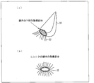
図11の(a)は鱗片33から発根している様子を表す斜視図であり、(b)は鱗片の発根部分を表す平面図である。
ニンニク30として、1つの鱗片(植物)33を棚板4に載置することで、鱗片33から根32を発根させることもできる。根32は、図11の(a)(b)に示すように、鱗片33の下部から周状に発根する。このため、切取台55を、円錐台として構成する場合、鱗片33に近い側の上底の面積は、鱗片33の下部の発根部分で囲まれている周状の面積より小さいことが好ましい。
これにより、鱗片33の根32が、切取台55の側面で、まんべんなく広がるようにコントロールすることができる。
また、切取台55の頂点を、ニンニク30の発根部分との距離を近づけることで、根32をより根元で切ることが可能となる。
図12は、根32を空気中で切り取る水耕栽培装置の様子を表す図である。
図12に示すように、根32を培養液3中ではなく、空気中で切る必要がある場合がある。このような場合、特に、培養液3の水面より上の部分に切取台55が突出している必要がある。
切り取った根32の根先(切り取り面)が培養液3中に浸かっていると、培養液3中のバクテリアの影響で根32が変色したり、培養液3の水質を悪化させたりする可能性がある。このような場合に、空気中で根32を切ることでこれを防ぐことが可能となる。
また、切取台55の側面の傾斜角度を調整することによっても、カッター52を押下することで切断されるニンニク30の根32の位置を調整することができる。
〔実施の形態4〕
本発明の根切り機構の第4の実施の形態について説明する。なお、説明の便宜上、実施の形態1~3にて説明した図面と同じ機能を有する部材については、同じ符号を付記し、その説明を省略する。
本発明の根切り機構の第4の実施の形態について説明する。なお、説明の便宜上、実施の形態1~3にて説明した図面と同じ機能を有する部材については、同じ符号を付記し、その説明を省略する。
図13は、第4の実施の形態に係る根切り機構を備えた水耕栽培装置の構成を表す断面図である。
図13に示すように、水耕栽培装置(植物栽培装置)60は、複数の根切り機構10a・10b・10cを備えている。水耕栽培装置60は、複数のニンニク30を栽培することができるものである。
水耕栽培装置60は、棚板4に替えて棚板64を備え、また、培養液タンク2に替えて培養液タンク62を備えている点で水耕栽培装置1と相違する。
培養液タンク62は、複数の根切り機構を内部に設置可能な程度の大きさで構成されている。本実施の形態では、培養液タンク62内には、3個の根切り機構10a・10b・10cが設置されている。
根切り機構10a・10b・10cは、それぞれ、カッター11と、刃12と、ストッパー13と、バネ14と、切取台45とを備えている。根切り機構10a・10b・10cのそれぞれは、水耕栽培装置60で栽培される複数のニンニク30のそれぞれに対応して水耕栽培装置60に設けられる。
棚板64は、水耕栽培装置60で複数のニンニク30を栽培するために、複数のニンニク30の鱗茎31を載置することができる程度の大きさで構成されている。
棚板64は、載置された複数のニンニク30の鱗茎31の発根部分のそれぞれに対応して、複数の開口部7が形成されている。さらに、棚板64には、載置される複数のニンニク30の鱗茎31のそれぞれの周囲を囲って、根切り機構10a・10b・10cのそれぞれのカッター11を挿設するための複数の開口部17が設けられている。そして、根切り機構10a・10b・10cのそれぞれのカッター11は、棚板64に形成された複数の開口部17のそれぞれに挿設されている。
このように、水耕栽培装置60は、複数の根切り機構10a・10b・10cを備え、根切り機構10a・10b・10cのそれぞれのカッター11が配されている棚板64が共通して構成されている。
これにより、水耕栽培装置60で、複数のニンニク30が栽培されていたとしても、当該複数のニンニク30のそれぞれを、棚板64から取り外すことなく、それぞれのニンニク30の根32を収穫することができる。これにより、効率よく、水耕栽培装置60でニンニク30を栽培することができると共に、ニンニク30の生育に及ぼす影響を抑制し、かつ、効率よくそれぞれのニンニク30の根32を収穫することができる。
このように、水耕栽培装置60では、培養液タンク62は1個のままで複数のニンニク30を栽培することができるので、コストを抑えて効率的に植物の栽培が可能である。
また、根切り機構10a・10b・10cそれぞれの切取台45は、接続部65によって、下面近傍で、互いに接続されている。そして、複数の切取台45及び接続部65の内部には、気泡発生管46よりも大きい気泡発生管(エアーストーン)66が配されている。気泡発生管66は、複数の切取台45に跨って配されている。そして、気泡発生管66は、切取台45の外部に設けられた送気ポンプ(不図示)と、中空チューブ68で繋がれている。
接続部65にも、酸素が通過できる複数の開口部47が形成されている。これにより、気泡発生管66から出力される酸素を、複数のニンニク30の根32の部分に効果的に行き渡らせることが可能となる。
なお、接続部65は必ずしも設ける必要はなく、根切り機構10a・10b・10cそれぞれの切取台45は互いに分離された構成であってもよい。この場合、気泡発生管66に替えて、根切り機構10a・10b・10cそれぞれの切取台45内部に納まるように、上述した気泡発生管46を設けることが好ましい。
〔実施の形態5〕
本発明の根切り機構の第5の実施の形態について説明する。なお、説明の便宜上、実施の形態1~4にて説明した図面と同じ機能を有する部材については、同じ符号を付記し、その説明を省略する。
本発明の根切り機構の第5の実施の形態について説明する。なお、説明の便宜上、実施の形態1~4にて説明した図面と同じ機能を有する部材については、同じ符号を付記し、その説明を省略する。
図14の(a)(b)は、第5の実施の形態に係る根切り機構を備えた水耕栽培装置の構成を表し、(a)は断面が台形である切取台を備えた水耕栽培装置を表す斜視図であり、(b)は、(a)の水耕栽培装置の平面図である。また、図15は、断面が三角形状である水耕栽培装置の構成を表す斜視図である。
図14の(a)(b)に示すように、水耕栽培装置1は、根切り機構71を備えている。根切り機構71は、切取台15に替えて切取台75を備え、また、カッター72の配置の仕方が、根切り機構10と相違する。
根切り機構71は、カッター(可動部)72と、刃12と、ストッパー13(図14の(a)(b)には不図示)と、バネ14(図14の(a)(b)には不図示)と、切取台75と、を備えている。カッター72は、横並びに配された複数のカッター72a・72b・72c・72dからなるカッター群(第1の可動部群)72Aと、横並びに配された複数のカッター72e・72f・72g・72hからなるカッター群(第2の可動部群)72Bとからなる。
図14の(a)に示すように、切取台75は、カッター(可動部)72を、下限まで押下したとき、カッター72に配された刃12と当接する側面(表面)を含むものである。
切取台75は、上方から下方にかけて、上記側面間の距離が、次第に広がっている。これにより、カッター72を押下したとき、カッター72に配された刃12を、切取台75の表面に当接させることができる。従って、カッター72を押下することで、ニンニク30の根32を収穫することができる。
切取台75の形状は、筋状に盛り上がった畝形状である。切取台75は、培養液タンク2の長手方向に延びて、筋状に形成されている。また、切取台75は、筋状に延びる方向である長手方向に直交する方向である短手方向の断面が台形である。台形の斜面が、上記側面である。
このように、切取台75は、形状の一例として畝形状として構成されている。これにより、棚板4に載置されたニンニク30の根32が、刃12と、切取台75の側面との間に配されることになる。ニンニク30の根32は、切取台75の側面に沿って伸びることになる。
このため、複数のカッター72a~72fのうち、押下されたカッター72a~72fによって、ニンニク30の根32は、切取台75の側面に押圧されて切断される。これにより、ニンニクの根32を確実に切り取ることができるので、効率よく、ニンニク30の根32を収穫することができる。
棚板4には、カッター72a~72hのそれぞれを挿設するための複数の開口部77が設けられている。そして、カッター72a~72fは、棚板4に設けられた複数の開口部77に挿設されている。カッター72a・72b・72c・72dのそれぞれと、カッター72e・72f・72g・72hのそれぞれとは、棚板4の長手方向に横並びに配されている。
カッター群72Aと、カッター群72Bとは、棚板4が支持するニンニク30を挟むことが可能な程度に離間して配されている。すなわち、カッター72a・72b・72c・72dのそれぞれと、カッター72e・72f・72g・72hのそれぞれとは、棚板4の短手方向に、互いに対向して、棚板4に配されている。ニンニク30は、カッター群72Aと、カッター群72Bとの間に配されている。
そして、カッター群72A及びカッター群72Bのそれぞれを構成するカッター72a~72fは、それぞれ独立して、押下されることが可能である。
このため、複数のカッター72a~72fのうち、押下されたカッター72a~72fの先端に配されている刃12によってだけニンニク30の根32を切り取ることができるので、ニンニク30の生育に及ぼす影響を抑制して、ニンニク30の根32を収穫することができる。
なお、棚板4の長手方向に配されているカッター72の個数は、本実施の形態のように4個に限定されず、5個以上であってもよいし、3個以下であってもよい。
さらに、図15に示すように、切取台の短手方向の断面を、台形ではなく、三角形にしてもよい。
図15の水耕栽培装置1は、根切り機構76を備えている。根切り機構76は、切取台75に替えて切取台78を備えている。切取台78の形状は、筋状に盛り上がった畝形状である。すなわち、切取台78は、培養液タンク2の長手方向に延びて、筋状に形成されている。
そして、切取台78の形状は、上記筋状に延びる方向(すなわち延設方向)と直交する方向の断面が三角形である。切取台78では、上記三角形の斜面が、カッター72の刃12と当接させるための側面である。これにより、切取台75と同様の効果を得ることができる。
また、図14の(a)(b)、図15に示した切取台75・78のように、形状を畝形状とすることで、複数の植物5の根32を切り取る根切り機構へと装置構成の拡張が容易となる。すなわち、棚板4に複数の植物5を載置し、栽培する場合、当該複数の植物5に共通する切取台75・78として構成することができる。このため、棚板4に、複数の植物5を載置する場合に、複数の植物5の間隔や密植度を自由に選択することができる。
また、カッター72は、カッター群72Aと、カッター群72Bとからなる。このため、同様に、複数の植物5の根32を切り取る根切り機構へと装置構成の拡張が容易となる。すなわち、棚板4に複数の植物5を載置し、栽培する場合、当該複数の植物5に共通して横並びに配された複数のカッター72からなるカッター群72Aと、カッター群72Bとを構成することができる。このため、棚板4に、複数の植物5を載置する場合に、複数の植物5の間隔や密植度を自由に選択することができる。
本発明は上述した各実施形態に限定されるものではなく、請求項に示した範囲で種々の変更が可能であり、異なる実施形態にそれぞれ開示された技術的手段を適宜組み合わせて得られる実施形態についても本発明の技術的範囲に含まれる。
以上のように、本発明の根切り機構は、植物の栽培を行なう植物栽培装置に取り付け可能であり、当該植物の根を切るための根切り機構であって、上記植物を支持する支持台に、押下されることが可能に配された可動部と、上記可動部の先端に配され、当該可動部が押下されることで、一部を残して上記植物の根を切り取る切取部とを備えていることを特徴としている。
上記構成によると、先端に切取部が配された可動部は、押下されることが可能に支持台に配されている。これにより、上記可動部を押下することで、支持台が支持する植物の根を切り取ることができる。
このため、上記支持台が支持する植物の根を切り取るために、当該植物を支持台から取り出す必要は無く、上記支持台に植物を載置したまま当該植物の根を切り取ることができるので、効率よく、植物の根を収穫することができる。
上記構成によると、上記切取部は、上記可動部が押下されることで、上記植物の根の一部を残して、当該植物の根を切り取る。このように、上記植物の根を全て切り取らず、一部を残して、上記植物の根を切り取ることで、上記植物の生育に及ぼす影響を抑制して、上記植物の根を収穫することができる。
このように、上記構成によると、植物栽培装置で栽培されている植物の生育に及ぼす影響を抑制し、かつ、効率よく上記植物の根を収穫することができる。
上記可動部は複数配されており、上記複数の可動部は、上記支持台が支持する植物の周囲を囲って配されており、それぞれ独立して、押下されることが可能であることが好ましい。
上記構成により、上記複数の可動部のうち、押下された可動部の先端に配されている切取部によってだけ上記植物の根を切り取り、押下されていない可動部に配されている切取部によっては、上記植物の根は切り取られない。すなわち、上記植物の根は、押下された可動部に配された切取部によってだけ収穫され、その他の部分は残される。
従って、上記植物の生育に及ぼす影響を抑制して、上記植物の根を収穫することができる。
上記可動部は、上記支持台が支持する上記植物の一部を囲って配されていることが好ましい。上記構成によると、上記支持台が支持する上記植物の根のうち、一部だけ、上記可動部が押下されることで上記切取部により切り取られ、その他の部分を残すことができる。
従って、上記植物の生育に及ぼす影響を抑制して、上記植物の根を収穫することができる。
上記支持台には、当該支持台が支持する上記植物の周囲を囲って配する複数の上記可動部を挿設するための複数の開口部が設けられており、上記可動部は、上記複数の開口部のうち、少なくとも何れかに挿設されていることが好ましい。
上記構成により、上記支持台が支持する上記植物の少なくとも一部を囲って、上記可動部を配することができる。このため、上記可動部を押下することで、上記植物の根の一部だけを切り取ることができる。
また、上記複数の開口部に挿設する可動部の個数を変更することで、上記植物の根を切り取る量、すなわち、上記植物の根の収穫量を調整することができる。
このため、上記植物の生育に及ぼす影響の抑制と、上記植物の根の収穫量とのバランスを、容易に取ることができる。
また、上記可動部を、下限まで押下したとき、当該可動部に配された切取部と当接する表面を含む切取台を備えていることが好ましい。
上記構成によると、上記支持台に植物が載置されると、当該載置された植物の根が、切取部と、上記切取台の表面との間に配されることになる。そして、上記複数の可動部のうち、押下された可動部に配された切取部によって、上記植物の根は、上記切取台の表面に押圧されて切断される。このため、上記植物の根を確実に切り取ることができるので、効率よく、上記植物の根を収穫することができる。
また、上記切取台は、上方から下方にかけて、上記表面間の距離が、次第に広がっていることが好ましい。これにより、上記可動部を押下したとき、当該可動部に配された切取部を、上記切取台の表面に当接させることができる。従って、上記可動部を押下することで、上記植物の根を収穫することができる。
また、上記切取台の形状は円錐又は円錐台であり、上記表面は当該円錐又は円錐台の側面であることが好ましい。または、上記切取台の形状は多角錐又は多角錐台であり、上記表面は当該多角錐又は多角錐台の側面であることが好ましい。
上記構成により、上記植物の根は、上記表面に沿って伸びることになる。これにより、上記可動部が押下されることで移動する上記切取部の軌跡上に、上記植物の根を存在させることができるので、より確実に、上記切取部によって上記植物の根を切り取ることができる。
さらに、上記切取台の形状は円錐又は円錐台とすることで、上記植物の根を切り取る量や位置を変更する場合、上記切取部の大きさや、個数を変更すればよく、切取台の形状を変更する必要が無い。このため、コスト増加を抑え、上記植物の生育に及ぼす影響の抑制と、上記植物の根の収穫量とのバランスを、容易に取ることができる。
また、上記切取台の形状は、筋状に盛り上がった畝形状であることが好ましい。
上記切取台の形状の一例として畝形状とすることで、上記切取台を構成することができる。上記構成によると、上記支持台に載置された植物の根が、切取部と、上記切取台の表面との間に配されることになる。このため、上記複数の可動部のうち、押下された可動部によって、上記植物の根は、上記切取台の表面に押圧されて切断される。これにより、上記植物の根を確実に切り取ることができるので、効率よく、上記植物の根を収穫することができる。
さらに、上記切取台の形状を畝形状とすることで、複数の植物の根を切り取る根切り機構へと装置構成の拡張が容易となる。すなわち、支持台に複数の植物を載置し、栽培する場合、当該複数の植物に共通する切取台として構成することができる。このため、支持台に、複数の植物を載置する場合に、複数の植物の間隔や密植度を自由に選択することができる。
また、上記切取台の形状は、上記筋状に延びる方向と直交する方向の断面が台形であることが好ましい。又は、上記切取台の形状は、上記筋状に延びる方向と直交する方向の断面が三角形であることが好ましい。
上記構成により、上記植物の根は、上記表面に沿って伸びることになるので、より確実に、上記切取部によって上記植物の根を切り取ることができる。
また、上記可動部は、横並びに配された複数の可動部からなる第1及び第2の可動部群からなり、上記第1の可動部群と、上記第2の可動部群とは、上記支持台が支持する植物を挟むことが可能な程度に離間して配されており、上記第1及び第2の可動部群のそれぞれを構成する上記可動部は、それぞれ独立して、押下されることが可能であることが好ましい。
上記構成により、上記複数の可動部のうち、押下された可動部の先端に配されている切取部によってだけ上記植物の根を切り取ることができるので、上記植物の生育に及ぼす影響を抑制して、上記植物の根を収穫することができる。
さらに、上記可動部は、横並びに配された複数の可動部からなる第1及び第2の可動部群からなるので、複数の植物の根を切り取る根切り機構へと装置構成の拡張が容易となる。すなわち、支持台に複数の植物を載置し、栽培する場合、当該複数の植物に共通して横並びに配された複数の可動部からなる第1及び第2の可動部群を構成することができる。このため、支持台に、複数の植物を載置する場合に、複数の植物の間隔や密植度を自由に選択することができる。
また、上記切取台の内部に配された気泡発生管を備え、上記切取台の表面には、上記気泡発生管から出力される気体を通す複数の開口部が設けられていることが好ましい。
上記構成により、例えば、上記切取台を水耕栽培装置に配した場合、当該水耕栽培装置で栽培されている植物の根に、効果的に酸素を供給することができる。
また、上記複数の可動部を平面視したとき、当該複数の可動部は、円形状となるように、上記支持台が支持する植物の周囲を囲って配されていることが好ましい。または、上記複数の可動部を平面視したとき、当該複数の可動部は、多角形状となるように、上記支持台が支持する植物の周囲を囲って配されていることが好ましい。
上記構成によると、上記切取台の形状に合せて、上記複数の可動部を、上記支持台が支持する植物の周囲を囲って配することができる。これにより、上記複数の可動部のそれぞれを押下することで、確実に、上記植物の根を切り取ることができる。
また、上記支持台には、上記可動部を、押下されることが可能に接続する接続部材が配されており、上記可動部は、上記接続部材によって接続されている箇所と、上記切取部が配されている箇所との間に、折れ曲った屈曲部を有することが好ましい。
上記構成により、上記屈曲部の形状を調整することで、上記可動部が押下された際の、当該可動部に配された切取部と、当該切取部が当接する切取台の表面との相対位置を変更することができる。このため、上記植物の根を切り取る位置を調整することができるので、利便性を向上させることができる。
また、上記植物はニンニクであることが好ましい。上記構成によると、ニンニクの生育に及ぼす影響を抑制し、かつ、効率よくニンニクの根を収穫することができる。
本発明の植物栽培装置は、上記根切り機構を備えていることが好ましい。上記構成により、上記植物栽培装置で栽培されている植物の生育に及ぼす影響を抑制し、かつ、効率よく上記植物の根を収穫することができる。
また、上記根切り機構を複数備え、当該複数の根切り機構の可動部が配されている支持台が共通して構成されていることが好ましい。上記構成により、上記植物栽培装置で、複数の植物が栽培されていたとしても、当該複数の植物のそれぞれを、上記支持台から取り外すことなく、それぞれの根を収穫することができる。これにより、効率よく、上記植物栽培装置で植物を栽培することができると共に、生育に及ぼす影響を抑制し、かつ、効率よくそれぞれの植物の根を収穫することができる。
本発明の水耕栽培装置は、水耕栽培によって、上記植物を栽培する上記植物栽培装置であることが好ましい。上記構成により、上記水耕栽培装置で栽培されている植物の生育に及ぼす影響を抑制し、かつ、効率よく上記植物の根を収穫することができる。
本発明は、人工的に植物を栽培する装置、及び当該装置で栽培されている植物の根を収穫する装置に適用することができる。
1、60 水耕栽培装置(植物栽培装置)
2、62 培養液タンク
3 培養液
4、64 棚板(支持台)
10、41、51、71、76 根切り機構
10a・10b・10c 根切り機構
11、21、23、25、27、28、52、72 カッター(可動部)
12 刃(切取部)
13 ストッパー(接続部材)
15、22、24、26、45、55、75、78 切取台
17 開口部
30 ニンニク(植物)
31 鱗茎(植物)
32 根
46、66 気泡発生管
47、77 開口部
53 屈曲部
72A カッター群(第1の可動部群)
72B カッター群(第2の可動部群)
2、62 培養液タンク
3 培養液
4、64 棚板(支持台)
10、41、51、71、76 根切り機構
10a・10b・10c 根切り機構
11、21、23、25、27、28、52、72 カッター(可動部)
12 刃(切取部)
13 ストッパー(接続部材)
15、22、24、26、45、55、75、78 切取台
17 開口部
30 ニンニク(植物)
31 鱗茎(植物)
32 根
46、66 気泡発生管
47、77 開口部
53 屈曲部
72A カッター群(第1の可動部群)
72B カッター群(第2の可動部群)
Claims (20)
- 植物の栽培を行なう植物栽培装置に取り付け可能であり、当該植物の根を切るための根切り機構であって、
上記植物を支持する支持台に、押下されることが可能に配された可動部と、
上記可動部の先端に配され、当該可動部が押下されることで、一部を残して上記植物の根を切り取る切取部とを備えていることを特徴とする根切り機構。 - 上記可動部は複数配されており、
上記複数の可動部は、上記支持台が支持する植物の周囲を囲って配されており、それぞれ独立して、押下されることが可能であることを特徴とする請求項1に記載の根切り機構。 - 上記可動部は、上記支持台が支持する上記植物の一部を囲って配されていることを特徴とする請求項1に記載の根切り機構。
- 上記支持台には、当該支持台が支持する上記植物の周囲を囲って配する複数の上記可動部を挿設するための複数の開口部が設けられており、
上記可動部は、上記複数の開口部のうち、少なくとも何れかに挿設されていることを特徴とする請求項3に記載の根切り機構。 - 上記可動部を、下限まで押下したとき、当該可動部に配された切取部と当接する表面を含む切取台を備えていることを特徴とする請求項1に記載の根切り機構。
- 上記切取台は、上方から下方にかけて、上記表面間の距離が、次第に広がっていることを特徴とする請求項5に記載の根切り機構。
- 上記切取台の形状は円錐又は円錐台であり、上記表面は当該円錐又は円錐台の側面であることを特徴とする請求項6に記載の根切り機構。
- 上記切取台の形状は多角錐又は多角錐台であり、上記表面は当該多角錐又は多角錐台の側面であることを特徴とする請求項6に記載の根切り機構。
- 上記切取台の形状は、筋状に盛り上がった畝形状であることを特徴とする請求項5に記載の根切り機構。
- 上記切取台の形状は、上記筋状に延びる方向と直交する方向の断面が台形であることを特徴とする請求項9に記載の根切り機構。
- 上記切取台の形状は、上記筋状に延びる方向と直交する方向の断面が三角形であることを特徴とする請求項9に記載の根切り機構。
- 上記可動部は、横並びに配された複数の可動部からなる第1及び第2の可動部群からなり、
上記第1の可動部群と、上記第2の可動部群とは、上記支持台が支持する植物を挟むことが可能な程度に離間して配されており、
上記第1及び第2の可動部群のそれぞれを構成する上記可動部は、それぞれ独立して、押下されることが可能であることを特徴とする請求項1に記載の根切り機構。 - 上記切取台の内部に配された気泡発生管を備え、
上記切取台の表面には、上記気泡発生管から出力される気体を通す複数の開口部が設けられていることを特徴とする請求項5に記載の根切り機構。 - 上記複数の可動部を平面視したとき、当該複数の可動部は、円形状となるように、上記支持台が支持する植物の周囲を囲って配されていることを特徴とする請求項2に記載の根切り機構。
- 上記複数の可動部を平面視したとき、当該複数の可動部は、多角形状となるように、上記支持台が支持する植物の周囲を囲って配されていることを特徴とする請求項2に記載の根切り機構。
- 上記可動部を、上記支持台に、押下されることが可能に接続する接続部材を備え、
上記可動部は、上記接続部材によって接続されている箇所と、上記切取部が配されている箇所との間に、折れ曲った屈曲部を有することを特徴とする請求項1~15の何れか1項に記載の根切り機構。 - 上記植物はニンニクであることを特徴とする請求項1~16の何れか1項に記載の根切り機構。
- 請求項1~17の何れか1項に記載の根切り機構と、上記支持台とを備えていることを特徴とする植物栽培装置。
- 上記根切り機構を複数備え、当該複数の根切り機構の可動部が配されている支持台が共通して構成されていることを特徴とする請求項18に記載の植物栽培装置。
- 請求項18又は19に記載の植物栽培装置は、水耕栽培によって、上記植物を栽培する装置であることを特徴とする水耕栽培装置。
Applications Claiming Priority (2)
| Application Number | Priority Date | Filing Date | Title |
|---|---|---|---|
| JP2010-195908 | 2010-09-01 | ||
| JP2010195908A JP2012050383A (ja) | 2010-09-01 | 2010-09-01 | 根切り機構、植物栽培装置、及び水耕栽培装置 |
Publications (1)
| Publication Number | Publication Date |
|---|---|
| WO2012029635A1 true WO2012029635A1 (ja) | 2012-03-08 |
Family
ID=45772727
Family Applications (1)
| Application Number | Title | Priority Date | Filing Date |
|---|---|---|---|
| PCT/JP2011/069207 Ceased WO2012029635A1 (ja) | 2010-09-01 | 2011-08-25 | 根切り機構、植物栽培装置、及び水耕栽培装置 |
Country Status (2)
| Country | Link |
|---|---|
| JP (1) | JP2012050383A (ja) |
| WO (1) | WO2012029635A1 (ja) |
Cited By (4)
| Publication number | Priority date | Publication date | Assignee | Title |
|---|---|---|---|---|
| CN103733856A (zh) * | 2013-12-26 | 2014-04-23 | 董金锋 | 一种大蒜高产栽培方法 |
| GB2514859A (en) * | 2013-04-17 | 2014-12-10 | Hanging Garden Uk Ltd | Hydroponic plant and root support |
| WO2018018717A1 (zh) * | 2016-07-25 | 2018-02-01 | 刘清泉 | 带有根须切断结构的定植器 |
| EP3903565A1 (en) * | 2020-04-30 | 2021-11-03 | Antonio Palumbo | A plant cutting and clone-growth device and related methods |
Families Citing this family (3)
| Publication number | Priority date | Publication date | Assignee | Title |
|---|---|---|---|---|
| ES2696627T3 (es) * | 2012-04-23 | 2019-01-17 | Greiner Bio One North America Inc | Soporte de cámara de teléfono y de muestra |
| CN106305276A (zh) * | 2016-08-19 | 2017-01-11 | 武冈市青钱柳茶业有限公司 | 一种青钱柳根扦插繁殖方法 |
| KR102282826B1 (ko) * | 2020-11-24 | 2021-07-28 | 주식회사 어밸브 | 뿌리 촬영용 빗면을 갖는 구조물을 포함하는 수경재배 장치 |
Citations (3)
| Publication number | Priority date | Publication date | Assignee | Title |
|---|---|---|---|---|
| JPH08149933A (ja) * | 1994-11-29 | 1996-06-11 | Mitsubishi Heavy Ind Ltd | 水耕栽培装置 |
| JP2000106774A (ja) * | 1998-10-02 | 2000-04-18 | Kyushu Electric Power Co Inc | 収穫装置 |
| JP2001136850A (ja) * | 1999-11-16 | 2001-05-22 | Line Kogyo Kk | 水耕栽培システム |
-
2010
- 2010-09-01 JP JP2010195908A patent/JP2012050383A/ja not_active Withdrawn
-
2011
- 2011-08-25 WO PCT/JP2011/069207 patent/WO2012029635A1/ja not_active Ceased
Patent Citations (3)
| Publication number | Priority date | Publication date | Assignee | Title |
|---|---|---|---|---|
| JPH08149933A (ja) * | 1994-11-29 | 1996-06-11 | Mitsubishi Heavy Ind Ltd | 水耕栽培装置 |
| JP2000106774A (ja) * | 1998-10-02 | 2000-04-18 | Kyushu Electric Power Co Inc | 収穫装置 |
| JP2001136850A (ja) * | 1999-11-16 | 2001-05-22 | Line Kogyo Kk | 水耕栽培システム |
Cited By (6)
| Publication number | Priority date | Publication date | Assignee | Title |
|---|---|---|---|---|
| GB2514859A (en) * | 2013-04-17 | 2014-12-10 | Hanging Garden Uk Ltd | Hydroponic plant and root support |
| GB2514859B (en) * | 2013-04-17 | 2015-07-22 | Hanging Garden Uk Ltd | Hydroponic plant and root support |
| CN103733856A (zh) * | 2013-12-26 | 2014-04-23 | 董金锋 | 一种大蒜高产栽培方法 |
| WO2018018717A1 (zh) * | 2016-07-25 | 2018-02-01 | 刘清泉 | 带有根须切断结构的定植器 |
| EP3903565A1 (en) * | 2020-04-30 | 2021-11-03 | Antonio Palumbo | A plant cutting and clone-growth device and related methods |
| US12120988B2 (en) | 2020-04-30 | 2024-10-22 | Antonio PALUMBO | Plant cutting and clone-growth device and related methods |
Also Published As
| Publication number | Publication date |
|---|---|
| JP2012050383A (ja) | 2012-03-15 |
Similar Documents
| Publication | Publication Date | Title |
|---|---|---|
| WO2012029635A1 (ja) | 根切り機構、植物栽培装置、及び水耕栽培装置 | |
| KR101570978B1 (ko) | 수경재배용 모종판 | |
| CA2781315C (en) | Covers for plant-growing media | |
| US4658542A (en) | Portable growing system | |
| US20130031834A1 (en) | Vertical planter system for orchids and epiphytic plants | |
| JP2008092939A (ja) | 植物容器用のホルダ | |
| US20160050857A1 (en) | Plant pot system | |
| JP2018174933A (ja) | 自然薯栽培器及び自然薯栽培システム | |
| KR950703845A (ko) | 채묘방법(seedling picking method) | |
| JP3170682U (ja) | 植物の成育管理装置 | |
| JP6771172B2 (ja) | 水耕栽培用植物保持具 | |
| CN204653202U (zh) | 一种猕猴桃盆栽的漏斗式栽培架 | |
| JP3214856U (ja) | 栽培ポット、および水耕栽培用パネル | |
| JP2017209106A (ja) | 自然薯栽培器及び自然薯栽培システム | |
| JP5464765B2 (ja) | 水耕栽培用培地 | |
| JP2017127223A (ja) | 水耕栽培装置 | |
| JP6425202B2 (ja) | 育苗用の栽培容器および樹木の苗木の栽培方法 | |
| CN104067897A (zh) | 一种榴莲的种植方法 | |
| KR20210052643A (ko) | 육묘 트레이 | |
| KR101341841B1 (ko) | 무토양 육묘포트 | |
| JP5896523B2 (ja) | 軟白部を有する葉菜類の生産方法 | |
| CN213523196U (zh) | 一种便捷育苗装土生根发育盆 | |
| KR20110101545A (ko) | 시설양묘용 용기받침대 | |
| CN203251710U (zh) | 育苗营养钵 | |
| JP2024021111A (ja) | 植物の栽培方法 |
Legal Events
| Date | Code | Title | Description |
|---|---|---|---|
| 121 | Ep: the epo has been informed by wipo that ep was designated in this application |
Ref document number: 11821652 Country of ref document: EP Kind code of ref document: A1 |
|
| NENP | Non-entry into the national phase |
Ref country code: DE |
|
| 122 | Ep: pct application non-entry in european phase |
Ref document number: 11821652 Country of ref document: EP Kind code of ref document: A1 |