WO2012024980A1 - Lampe de type cheminée comportant une source de lumière à diodes électroluminescentes disposée sous la forme de deux plans opposés - Google Patents
Lampe de type cheminée comportant une source de lumière à diodes électroluminescentes disposée sous la forme de deux plans opposés Download PDFInfo
- Publication number
- WO2012024980A1 WO2012024980A1 PCT/CN2011/076504 CN2011076504W WO2012024980A1 WO 2012024980 A1 WO2012024980 A1 WO 2012024980A1 CN 2011076504 W CN2011076504 W CN 2011076504W WO 2012024980 A1 WO2012024980 A1 WO 2012024980A1
- Authority
- WO
- WIPO (PCT)
- Prior art keywords
- lamp
- led
- led light
- lampshade
- led lamp
- Prior art date
- Legal status (The legal status is an assumption and is not a legal conclusion. Google has not performed a legal analysis and makes no representation as to the accuracy of the status listed.)
- Ceased
Links
Images
Classifications
-
- F—MECHANICAL ENGINEERING; LIGHTING; HEATING; WEAPONS; BLASTING
- F21—LIGHTING
- F21S—NON-PORTABLE LIGHTING DEVICES; SYSTEMS THEREOF; VEHICLE LIGHTING DEVICES SPECIALLY ADAPTED FOR VEHICLE EXTERIORS
- F21S6/00—Lighting devices intended to be free-standing
- F21S6/002—Table lamps, e.g. for ambient lighting
-
- F—MECHANICAL ENGINEERING; LIGHTING; HEATING; WEAPONS; BLASTING
- F21—LIGHTING
- F21K—NON-ELECTRIC LIGHT SOURCES USING LUMINESCENCE; LIGHT SOURCES USING ELECTROCHEMILUMINESCENCE; LIGHT SOURCES USING CHARGES OF COMBUSTIBLE MATERIAL; LIGHT SOURCES USING SEMICONDUCTOR DEVICES AS LIGHT-GENERATING ELEMENTS; LIGHT SOURCES NOT OTHERWISE PROVIDED FOR
- F21K9/00—Light sources using semiconductor devices as light-generating elements, e.g. using light-emitting diodes [LED] or lasers
- F21K9/20—Light sources comprising attachment means
- F21K9/23—Retrofit light sources for lighting devices with a single fitting for each light source, e.g. for substitution of incandescent lamps with bayonet or threaded fittings
-
- F—MECHANICAL ENGINEERING; LIGHTING; HEATING; WEAPONS; BLASTING
- F21—LIGHTING
- F21V—FUNCTIONAL FEATURES OR DETAILS OF LIGHTING DEVICES OR SYSTEMS THEREOF; STRUCTURAL COMBINATIONS OF LIGHTING DEVICES WITH OTHER ARTICLES, NOT OTHERWISE PROVIDED FOR
- F21V29/00—Protecting lighting devices from thermal damage; Cooling or heating arrangements specially adapted for lighting devices or systems
- F21V29/50—Cooling arrangements
- F21V29/70—Cooling arrangements characterised by passive heat-dissipating elements, e.g. heat-sinks
- F21V29/74—Cooling arrangements characterised by passive heat-dissipating elements, e.g. heat-sinks with fins or blades
- F21V29/77—Cooling arrangements characterised by passive heat-dissipating elements, e.g. heat-sinks with fins or blades with essentially identical diverging planar fins or blades, e.g. with fan-like or star-like cross-section
- F21V29/773—Cooling arrangements characterised by passive heat-dissipating elements, e.g. heat-sinks with fins or blades with essentially identical diverging planar fins or blades, e.g. with fan-like or star-like cross-section the planes containing the fins or blades having the direction of the light emitting axis
-
- F—MECHANICAL ENGINEERING; LIGHTING; HEATING; WEAPONS; BLASTING
- F21—LIGHTING
- F21V—FUNCTIONAL FEATURES OR DETAILS OF LIGHTING DEVICES OR SYSTEMS THEREOF; STRUCTURAL COMBINATIONS OF LIGHTING DEVICES WITH OTHER ARTICLES, NOT OTHERWISE PROVIDED FOR
- F21V3/00—Globes; Bowls; Cover glasses
- F21V3/04—Globes; Bowls; Cover glasses characterised by materials, surface treatments or coatings
- F21V3/049—Patterns or structured surfaces for diffusing light, e.g. frosted surfaces
-
- F—MECHANICAL ENGINEERING; LIGHTING; HEATING; WEAPONS; BLASTING
- F21—LIGHTING
- F21Y—INDEXING SCHEME ASSOCIATED WITH SUBCLASSES F21K, F21L, F21S and F21V, RELATING TO THE FORM OR THE KIND OF THE LIGHT SOURCES OR OF THE COLOUR OF THE LIGHT EMITTED
- F21Y2115/00—Light-generating elements of semiconductor light sources
- F21Y2115/10—Light-emitting diodes [LED]
Definitions
- the invention is a lampshade lamp of two opposite planar LED light sources, which is characterized by two plane-opposed lampshade type LED lamp design structures, wherein a planar structure is an LED illumination source, and the provided radiation light allows the area under the lampshade. There will be no shadow generation.
- LED lamps Because of the requirements of environmental protection and energy saving, LED lamps have the advantages of low power consumption, long life, no pollution, and have become an urgently needed light source. In order to meet the needs of various markets, flat LED lighting fixtures have made significant progress, how to minimize the number of chip requirements, increase brightness and provide better lighting effects for houses. In order to shield the heat of incandescent lamps with high power consumption, the lampshade was used as early as the 19th century. When the lampshade is used on a flat LED lamp, a shadow area is formed under the lampshade because the LED chip is a polar diffused light beam. This shortcoming is detrimental to its aesthetic decorative function and reduces the market value of LED lighting.
- the object of the present invention is to provide a lampshade lamp with two opposite planar LED light sources, which is a planar LED lighting device, which can solve the problem of shadow formation under the lampshade due to the polar diffusion beam of the planar LED lamp.
- the invention provides a lampshade lamp with two opposite planar LED light sources, comprising: a planar LED lamp illumination structure device, comprising at least one pair of heat dissipation caps, at least one pair of heat sinks and at least one respectively mounted on the concave mirrors a top and bottom circuit board device; and a power connector extending from at least one pair of circuit boards for power connection.
- the lampshade lamp of the two opposite planar LED light sources comprises a planar LED lamp illumination structure device, which is used as an illumination source, and provides 360 degree radiation illumination under the lampshade, which can effectively avoid the flat LED lamp pole below the lampshade The problem of the diffused beam forming a shadow.
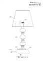
- Figure 1 shows the design of a traditional single-plane shade LED lamp
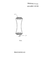
- 2A is a lampshade lamp structure of two opposite planar LED light sources according to a specific example of the present invention
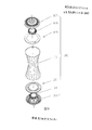
- 2B is an exploded view showing the structure of a planar LED lighting device according to a specific example of the present invention.
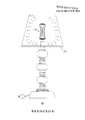
- Fig. 3 is a view showing the structure of a lampshade type LED lamp device according to a specific example of the present invention.
- Figure 1 shows a conventional lampshade type LED lamp.
- 2 is a specific example of an LED lamp designed in accordance with the present invention.
- Figure 3 is a combination of two opposite planar LED lamps.
- a conventional single-plane LED lamp 100 includes a single illumination source, a lampshade 101, a lamp body 102, a lamp holder, a transformer plug 104, and a switch.
- a single source 100 is used for the illumination source, and a shade 101 is used to avoid scattering light.
- the lamp body 102 is used to adjust the light source to a desired height.
- the socket 103 is used to stabilize the lamp body from tilting.
- a transformer plug 104 is used to connect the power source.
- the switch 105 can be two-stage (on/off) or three-stage (on/off) / dimmer) control connection power. Because of the way in which the LED beam is formed, a shaded area is formed behind the LED panel, as shown by the slanted dashed line on the underside of the lampshade 101 in FIG.
- FIG. 2A is a modification of the structure of a lampshade lamp of two opposite planar LED light sources of the present invention, in accordance with a specific example of the present invention, in the context of the structure shown in FIG. 1.
- the planar LED illuminator structure 106 is secured to the top of the lamp body and under the lampshade using mounting spiral tubing 114, wherein the planar LED lamp illumination structure 106 includes two illumination scattering regions, the opposite locations of which are indicated by two arrows.
- FIG. 2B is an assembled and exploded schematic view of the planar LED lamp illumination structure 106, which includes at least one pair of heat dissipation caps 107, 113. At least one pair of heat sinks 108, 112, and at least one pair of aluminum-based circuit boards 109, 111 are respectively mounted on the bottom and top end portions of the concave mirror 110 made of glass or plastic. That is, a flat LED light illumination structure 106 is provided with an LED light board at the top and bottom, and an LED light board is installed at both ends of the concave mirror 110. The scattering areas of the top LED panel and the bottom LED panel are opposite each other. The two LED panels are mounted on the circuit board, facing away from the heat sink and the heat sink cap, and the power connector extends from the board for connection to the power supply.
- FIG. 3 is an assembly diagram of the LED lamp of the present invention, which comprises a planar LED lamp illumination structure device 106, which is used as an illumination source, and provides 360-degree radiation illumination under the lampshade 101, which can effectively avoid the flat LED lamp below the lampshade.
Landscapes
- Engineering & Computer Science (AREA)
- General Engineering & Computer Science (AREA)
- Physics & Mathematics (AREA)
- Microelectronics & Electronic Packaging (AREA)
- Optics & Photonics (AREA)
- Non-Portable Lighting Devices Or Systems Thereof (AREA)
- Arrangement Of Elements, Cooling, Sealing, Or The Like Of Lighting Devices (AREA)
Abstract
L'invention porte sur une lampe de type cheminée comportant une source de lumière à diodes électroluminescentes disposée sous la forme de deux plans opposés, laquelle lampe comprend un miroir réfléchissant concave (110). Deux extrémités du miroir réfléchissant concave (110) sont équipées de plaques de lampe à diodes électroluminescentes. Les régions de dispersion des plaques de lampe supérieure et inférieure sont en regard l'une à l'autre. Deux plaques de diodes électroluminescentes sont installées sur les cartes de circuit (109, 111) avec leurs côtés arrière vers des radiateurs (108, 112) et des capuchons de rayonnement (107, 113). Un connecteur d'alimentation venant de deux cartes de circuit (109, 111) est disposé sur la plaque de lampe à diodes électroluminescentes, et est connecté à un cordon d'alimentation. Le dispositif de structure d'éclairage de lampe à diodes électroluminescentes du type plan (106) de la lampe est utilisé comme source de lumière d'éclairage sous un abat-jour (101), de façon à produire un éclairage à 360 degrés et à empêcher des ombres formées par des faisceaux de lumière à diffusion polaire de la lampe à diodes électroluminescentes du type plan sous l'abat-jour (101).
Applications Claiming Priority (2)
| Application Number | Priority Date | Filing Date | Title |
|---|---|---|---|
| US12/860,873 US20120043876A1 (en) | 2010-08-21 | 2010-08-21 | Two Confronting Planar LED Lamps with Shades |
| US12/860,873 | 2010-08-21 |
Publications (1)
| Publication Number | Publication Date |
|---|---|
| WO2012024980A1 true WO2012024980A1 (fr) | 2012-03-01 |
Family
ID=45593508
Family Applications (1)
| Application Number | Title | Priority Date | Filing Date |
|---|---|---|---|
| PCT/CN2011/076504 Ceased WO2012024980A1 (fr) | 2010-08-21 | 2011-06-28 | Lampe de type cheminée comportant une source de lumière à diodes électroluminescentes disposée sous la forme de deux plans opposés |
Country Status (2)
| Country | Link |
|---|---|
| US (1) | US20120043876A1 (fr) |
| WO (1) | WO2012024980A1 (fr) |
Cited By (3)
| Publication number | Priority date | Publication date | Assignee | Title |
|---|---|---|---|---|
| CN103196063A (zh) * | 2013-04-22 | 2013-07-10 | 深圳市裕富照明有限公司 | Led大角度发光球泡灯 |
| RU2634701C2 (ru) * | 2013-09-27 | 2017-11-03 | Хуавэй Текнолоджиз Ко., Лтд. | Обратная связь harq с использованием агрегации несущих |
| CN109027747A (zh) * | 2018-06-29 | 2018-12-18 | 安徽新店软件开发有限公司 | 一种带纳米反光板台灯的散热装置 |
Families Citing this family (3)
| Publication number | Priority date | Publication date | Assignee | Title |
|---|---|---|---|---|
| CN108253334B (zh) * | 2017-12-13 | 2020-06-16 | 佛山市南海区联合广东新光源产业创新中心 | 一种led装饰灯 |
| USD964633S1 (en) * | 2021-02-01 | 2022-09-20 | Bo Luo | Crystal lamp |
| USD1047264S1 (en) * | 2022-09-14 | 2024-10-15 | Ningbo Ucome Lighting Co., Ltd. | Lamp |
Citations (5)
| Publication number | Priority date | Publication date | Assignee | Title |
|---|---|---|---|---|
| US20080239723A1 (en) * | 2007-03-27 | 2008-10-02 | Ama Precision Inc. | Led table lamp |
| CN101457915A (zh) * | 2007-12-14 | 2009-06-17 | 富准精密工业(深圳)有限公司 | 发光二极管灯具 |
| CN101457899A (zh) * | 2007-12-11 | 2009-06-17 | 精碟科技股份有限公司 | 无多重阴影的发光二极管灯具结构 |
| CN201354962Y (zh) * | 2009-02-24 | 2009-12-02 | 金松山 | Led照明灯 |
| CN201373345Y (zh) * | 2009-03-13 | 2009-12-30 | 常州市寿琛工具制造有限公司 | 大功率led手术无影灯的灯座组件 |
-
2010
- 2010-08-21 US US12/860,873 patent/US20120043876A1/en not_active Abandoned
-
2011
- 2011-06-28 WO PCT/CN2011/076504 patent/WO2012024980A1/fr not_active Ceased
Patent Citations (5)
| Publication number | Priority date | Publication date | Assignee | Title |
|---|---|---|---|---|
| US20080239723A1 (en) * | 2007-03-27 | 2008-10-02 | Ama Precision Inc. | Led table lamp |
| CN101457899A (zh) * | 2007-12-11 | 2009-06-17 | 精碟科技股份有限公司 | 无多重阴影的发光二极管灯具结构 |
| CN101457915A (zh) * | 2007-12-14 | 2009-06-17 | 富准精密工业(深圳)有限公司 | 发光二极管灯具 |
| CN201354962Y (zh) * | 2009-02-24 | 2009-12-02 | 金松山 | Led照明灯 |
| CN201373345Y (zh) * | 2009-03-13 | 2009-12-30 | 常州市寿琛工具制造有限公司 | 大功率led手术无影灯的灯座组件 |
Cited By (3)
| Publication number | Priority date | Publication date | Assignee | Title |
|---|---|---|---|---|
| CN103196063A (zh) * | 2013-04-22 | 2013-07-10 | 深圳市裕富照明有限公司 | Led大角度发光球泡灯 |
| RU2634701C2 (ru) * | 2013-09-27 | 2017-11-03 | Хуавэй Текнолоджиз Ко., Лтд. | Обратная связь harq с использованием агрегации несущих |
| CN109027747A (zh) * | 2018-06-29 | 2018-12-18 | 安徽新店软件开发有限公司 | 一种带纳米反光板台灯的散热装置 |
Also Published As
| Publication number | Publication date |
|---|---|
| US20120043876A1 (en) | 2012-02-23 |
Similar Documents
| Publication | Publication Date | Title |
|---|---|---|
| JP3159158U (ja) | 良好な照明輝度を具えたled照明装置 | |
| JP3162351U (ja) | 両面式led照明装置 | |
| JP3158327U (ja) | 輝度アップ可能なled照明装置 | |
| WO2009015605A1 (fr) | Lampe tunnel à del | |
| US20130279164A1 (en) | Led lighting fixtures | |
| KR20090012706A (ko) | 고출력 엘이디 가로등 | |
| WO2012024980A1 (fr) | Lampe de type cheminée comportant une source de lumière à diodes électroluminescentes disposée sous la forme de deux plans opposés | |
| JP2013098100A (ja) | 360度全射角の高照度ledバルブ | |
| CN201344429Y (zh) | 一种led天花灯 | |
| WO2012116478A1 (fr) | Lampe à diodes électroluminescentes (del) | |
| CN101761814A (zh) | 一种led光源模块以及包含该模块的led球泡灯、射灯和筒灯 | |
| CN201373315Y (zh) | 一种易散热led天花灯 | |
| CN102080792B (zh) | 反射式led天幕灯 | |
| TWM335632U (en) | Reflection module for LED lighting apparatus | |
| KR100945173B1 (ko) | 발광다이오드 조명등 | |
| CN202484670U (zh) | 一种led筒灯 | |
| CN110553191B (zh) | 一种基础照明和重点照明的组合式灯具 | |
| CN211083750U (zh) | 一种led灯 | |
| CN201428951Y (zh) | Led灯体 | |
| CN207729485U (zh) | 一种聚光与泛光组合、可见光与红外光双模式机外灯具 | |
| KR20110011847A (ko) | 눈부심이 없는 패널 일체형 조명장치 | |
| CN219140721U (zh) | 一种投光灯散热结构 | |
| CN107435870B (zh) | 易散热的led面光源射灯 | |
| CN221424728U (zh) | 一种建筑外墙装饰照明灯组 | |
| CN214535883U (zh) | 一种兼具照明和情境调节的筒射灯 |
Legal Events
| Date | Code | Title | Description |
|---|---|---|---|
| 121 | Ep: the epo has been informed by wipo that ep was designated in this application |
Ref document number: 11819355 Country of ref document: EP Kind code of ref document: A1 |
|
| NENP | Non-entry into the national phase |
Ref country code: DE |
|
| 122 | Ep: pct application non-entry in european phase |
Ref document number: 11819355 Country of ref document: EP Kind code of ref document: A1 |