WO2012020493A1 - 局所冷却システム - Google Patents
局所冷却システム Download PDFInfo
- Publication number
- WO2012020493A1 WO2012020493A1 PCT/JP2010/063677 JP2010063677W WO2012020493A1 WO 2012020493 A1 WO2012020493 A1 WO 2012020493A1 JP 2010063677 W JP2010063677 W JP 2010063677W WO 2012020493 A1 WO2012020493 A1 WO 2012020493A1
- Authority
- WO
- WIPO (PCT)
- Prior art keywords
- refrigerant
- condenser
- heat source
- cold heat
- temperature
- Prior art date
- Legal status (The legal status is an assumption and is not a legal conclusion. Google has not performed a legal analysis and makes no representation as to the accuracy of the status listed.)
- Ceased
Links
Images




Classifications
-
- F—MECHANICAL ENGINEERING; LIGHTING; HEATING; WEAPONS; BLASTING
- F24—HEATING; RANGES; VENTILATING
- F24F—AIR-CONDITIONING; AIR-HUMIDIFICATION; VENTILATION; USE OF AIR CURRENTS FOR SCREENING
- F24F13/00—Details common to, or for air-conditioning, air-humidification, ventilation or use of air currents for screening
- F24F13/22—Means for preventing condensation or evacuating condensate
Definitions
- the present invention relates to a localized cooling system, and more particularly to condensation prevention control in the localized cooling unit.
- Patent Document 1 discloses a condensation prevention control method.
- condensation is avoided by adjusting the output amounts of the refrigerant pumping device and the cold heat source based on the temperature difference between the dew point temperature and the refrigerant temperature.
- the refrigerant pump rotation speed of the refrigerant pumping device is lowered, there is a possibility that the pump will stop due to lack of motor starting torque, and if the refrigerator output of the cold heat source is lowered similarly (rotation speed of compressor Lowers the compressor start torque due to lack of compressor starting torque.
- An object of the present invention is to provide a local cooling system capable of performing highly reliable condensation avoidance cooling operation without the possibility of refrigerant pump stop, refrigerator stop, and the like.
- the local cooling system of the present invention comprises a local cooling unit for cooling inflowing warm air and delivering it to a local area, a cold heat source unit for supplying a first refrigerant to the local cooling unit, and a second refrigerant for the cold source unit.
- a condenser for supplying the first refrigerant cooled by the second refrigerant, the first refrigerant cooled by the second refrigerant.
- the refrigerant supply apparatus for delivering the refrigerant to the local cooling unit, the cooling circuit delivers the second refrigerant to the condenser via the delivery pipe, and the condenser circuit outputs the second refrigerant from the condenser via the return pipe.
- An air conditioning system having a cold heat source for refluxing the two refrigerants, and the local cooling unit having an evaporator for cooling the inflowing warm air by the first refrigerant sent by the refrigerant supply device;
- Dew point temperature measuring means for measuring the dew point temperature of the inflowing warm air
- refrigerant temperature measuring means for measuring the temperature of the first refrigerant flowing into the evaporator, temperature of the dew point temperature and the first refrigerant temperature
- Condensation occurrence judging means for judging whether condensation is likely to occur or not on the basis of the difference, and sending a part of the second refrigerant returned from the condenser to the delivery pipe without passing through the cold heat source If it is determined by the valve device and the dew condensation occurrence judging means that condensation is likely to occur, the valve device is controlled so that a part of the second refrigerant returned from the condenser does not go through the cold heat source
- valve control means for raising the temperature of the second refrigerant flowing
- the temperature of the second refrigerant returned from the condenser is higher than the temperature of the second refrigerant flowing into the condenser. Therefore, by controlling the three-way valve, part of the second refrigerant returned from the condenser can be sent to the delivery pipe to be mixed with the second refrigerant from the cold heat source when condensation may occur. , The temperature of the second refrigerant flowing into the condenser can be raised. If the temperature of the second refrigerant rises, the temperature of the first refrigerant supplied to the local cooling unit also rises, and if, for example, the temperature of the second refrigerant is gradually raised, there is no possibility of condensation occurring either The determination is made, and the occurrence of condensation can be avoided.
- FIG. 1 shows a cross-sectional view of the entire configuration including the local cooling system of the present example.
- a plurality of rows of equipment storage racks 1 are provided in an arbitrary indoor space 25 having a high heat generation density, such as a computer room containing a large number of computers. Electronic devices and the like are accommodated in the device accommodation racks 1. Although two rows of equipment storage racks 1a and 1b are shown here, the present invention is not limited to this example.
- a cooling unit 2 (local cooling device; local air conditioner) is provided above each equipment storage rack 1. Although only two cooling units 2 are shown here, the cooling units 2 are provided at various places in the indoor space 25 (in particular, above the equipment storage racks 1).
- the basic configuration itself of the cooling unit 2 may be substantially the same as the conventional one, and although not described in detail here, it is a configuration having the evaporator 6, the blower 9 and the like.
- the refrigerant sent from the cold heat source unit 18 common to the respective cooling units 2 flows into the evaporator 6 through a pipe.
- the warm air flowing into the cooling unit 2 is cooled by the evaporator 6, and the cooling air (cold air) is blown by the blower 9 to a predetermined local space for cooling (for example, the space between the equipment storage racks 1a and 1b). It is sent out.
- one cold heat source unit 18 may be configured to supply the refrigerant to a plurality of cooling units 2, but the present invention is not limited to this example, and a cold heat source corresponding to each cooling unit 2 A unit 18 may be present. That is, one cold heat source unit 18 may be configured to supply the refrigerant only to one cooling unit 2.
- FIG. 2 the detailed block diagram of the local cooling system of this example is shown. Although this mainly shows the detailed structure of the said cooling unit 2 and the cold-heat source unit 18, these detailed structures may be fundamentally substantially the same as the past.
- a cooling circuit 11 shown in FIG. 2 exists as a configuration for supplying the refrigerant to the cold heat source unit 18.
- a refrigerant for example, coolant, cold water, etc.
- the features of the present system different from the conventional are mainly cooling of the configuration shown in FIG.
- the circuit 11 is provided (in particular, the three-way valve 24 is provided), and the control process of the three-way valve 24 is performed to adjust the output amounts of the refrigerant supply device 16 (for example, the refrigerant pump) and the cold heat source 20 It is possible to avoid the occurrence of dew condensation in the illustrated cooling circuit 7 (particularly the evaporator 6) without taking place (thereby without causing a refrigerant pump stop, a refrigerator stop, etc.).
- the refrigerant supply device 16 for example, the refrigerant pump
- the cold heat source 20 It is possible to avoid the occurrence of dew condensation in the illustrated cooling circuit 7 (particularly the evaporator 6) without taking place (thereby without causing a refrigerant pump stop, a refrigerator stop, etc.).
- the refrigerant (the refrigerant supplied from the cold heat source 20 to the condenser 12) in the cooling circuit 11 is a cooling liquid (cold water etc.)
- a cooling liquid cold water etc.
- the refrigerant supplied to the evaporator 6 may be a coolant (cold water or the like).
- the three-way valve 24 is provided and condensation control can be avoided by the control thereof, the pump stop due to the motor start torque shortage and the refrigerator stop due to the compressor start torque shortage do not occur as in the prior art. There is a high condensation avoidance cooling operation.
- the three-way valve 24 is used as an example here, any mechanism capable of branching (or mixing) the flow rate and controlling the flow rate may be used, for example, combining a plurality of bifurcated pipes with a cock and a control valve. You may configure it. Such things are generically called a valve apparatus. And, in the present description, the three-way valve 24 which is an example of the valve device will be described as an example.
- the cooling unit 2 is configured to receive the warm air discharged from the back side of the equipment storage rack 1 having the heating element such as the electronic device, the suction port 3 and the air.
- the heating element is cooled by blowing air to the front side of the rack 1.
- the refrigerant sent from the cold heat source unit 18 flows into the evaporator 6 through the expansion valve 5, and the refrigerant is evaporated in the evaporator 6 to obtain latent heat of evaporation.
- the surrounding refrigerant is cooled by absorbing from the surrounding, and the evaporative refrigerant is returned to the cold heat source unit 18.
- the valve-like one shown on the right side of the expansion valve 5 is a solenoid valve, and the refrigerant flows into the evaporator 6 through the solenoid valve, but it is not particularly relevant here.
- the cooling unit 2 further includes a control device 10 and an arithmetic communication device 23.
- the control device 10 is, for example, a microcomputer, and executes a predetermined application program stored in advance to perform various types of existing general controls (for example, the valve opening degree of the expansion valve 5 and the air flow rate of the air blower 9). Control etc.) may be performed, and part of processing related to dew point avoidance of the present method described later may be performed.
- the arithmetic communication device 23 is basically a functional unit that communicates with the outside, and communicates with the control device 17 via a communication line (indicated by a dotted line) in the illustrated example.
- the arithmetic communication device 23 may have, for example, an MPU (not shown) and the like, and may execute part of processing related to dew point avoidance of the present method described later, but the control device 10 performs this processing.
- the arithmetic communication device 23 may be a mere communication device (does not perform arithmetic processing). Details will be described later.
- the cooling unit 2 further includes a thermometer (indicated by "TC” in the figure) that measures the temperature of each place in the unit 2, and a hygrometer (indicated by "MC” in the figure) that measures humidity.
- TC thermometer
- MC hygrometer
- Each thermometer / hygrometer and the control device 10 are connected by a communication line (indicated by a dotted line), and the control device 10 measures temperature data / humidity data measured by each thermometer / hygrometer. Are collected from time to time.
- thermometer 21 and hygrometer 22 are provided on the warm air intake path between the air filter 4 and the evaporator 6 (upstream of the evaporator 6). These are for determining the dew point temperature of the intake warm air. Therefore, instead of the thermometer 21 and the hygrometer 22, a dew point thermometer may be provided.
- the control device 10 calculates the dew point temperature (at suction and warm air) at the installation location of the thermometer 21 and the hygrometer 22 based on the temperature data and the humidity data measured by the thermometer 21 and the hygrometer 22. Do.
- the equation for calculating the dew point temperature is well known and will not be described here.
- the control apparatus 10 only acquires the dew point temperature data measured by the dew point thermometer.
- the illustrated thermometer 26 is, for example, a thermometer for measuring the temperature of the refrigerant (at the evaporator inlet) immediately before flowing into the evaporator 6.
- the present invention is not limited to this example, and may measure, for example, the surface temperature of the evaporator 6 (in this case, also in this case, the measured temperature is regarded as the refrigerant temperature).
- Control processing of the three-way valve 24 is performed based on the dew point temperature and the refrigerant temperature. This will be described later with reference to the flow chart.
- control device 17 the cold heat source unit 18, the cooling circuit 11, and the like will be described.
- control device 17 is a device that controls the entire local cooling system of this example, and controls the cooling unit 2, the cold heat source unit 18, the cooling circuit 11, and the like.
- the control device 17 has a microcomputer and the like, and performs various controls by the CPU executing predetermined application programs stored in advance. The general various controls conventionally performed are not particularly described here. Only the control related to this method will be described.
- the control device 17 may perform control in accordance with any instruction from the instruction device 19.
- the command device 19 instructs the control device 17 the air flow rate and the cold air temperature of the cooling unit 2.
- the control device 17 performs various control operations in response to this instruction (as described above, the existing general control, which is not particularly described here).
- the control device 17 has a feature of having a control processing function of the valve opening degree of the three-way valve 24 described later, in addition to the conventional control processing function.
- the other than this characteristic part may be substantially similar to the conventional one.
- the cold heat source unit 18 may be the same as the conventional one as described above, and if briefly described, has the condenser 12, the receiver 13, and the refrigerant supply device 16, and also thermometers at various places (see FIG.
- the controller 17 is provided with a flowmeter (indicated by "QC" in the figure) for measuring the flow rate of the refrigerant output from the refrigerant supply device 16.
- QC flowmeter
- the refrigerant supply device 16 is controlled based on flow rate data and the like.
- a command is issued to each cooling unit 2.
- the evaporative refrigerant from the evaporator 6 flows into the condenser 12 and is cooled and liquefied to be returned to the refrigerant.
- the refrigerant is temporarily stored in the liquid receiver 13, and then sent out to the cooling unit 2 side by the refrigerant supply device 16 and flows into the evaporator 6.
- the cooling fluid is supplied to the condenser 12 from a cooling circuit 11 (a part surrounded by an alternate long and short dash line in the figure; a cold heat source 20 may be included). That is, the cooling fluid (for example, cold water or the like) from the cold heat source 20 is sent to the condenser 12 through the delivery pipe 27, and the cooling / liquefying of the evaporation refrigerant is performed by the cold water. This cools the evaporative refrigerant while warming the cold water (this is referred to as hot water). The hot water is returned to the cold heat source 20 through the return pipe 28, and is cooled by the cold heat source 20 to be cold water again and delivered to the delivery pipe 27.
- a cold heat source 20 may be included. That is, the cooling fluid (for example, cold water or the like) from the cold heat source 20 is sent to the condenser 12 through the delivery pipe 27, and the cooling / liquefying of the evaporation refrigerant is performed by the cold water. This cools the e
- a three-way valve 24 is provided in the middle of the return pipe 28.
- the three-way valve 24 of the present example is of a type (a type in which a pipeline is branched) including an inlet from one direction and an outlet in two directions.
- the three-way valve 24 is provided in the middle of the return pipe 28 and the inlet is connected to the return pipe 28 on the condenser 12 side, and the outlets in two directions are one on the cold heat source 20 side. It is connected to a return pipe 28 (here denoted as return pipe 28 'as shown) and the other is connected to a shorting pipe 29 as shown.
- the other of the shorting tubes 29 is connected to the delivery tube 27. That is, it has a structure capable of flowing out hot water or the like directly to the delivery pipe 27 via the shorting pipe 29.
- a valve is provided at each of the outlets of the three-way valve 24 in the two directions, and the control device 17 is configured to be able to adjust and control the degree of opening of each valve.
- the hot water returned from the condenser 12 side can be distributed to the cold heat source 20 side and the delivery pipe 27 side.
- the distribution ratio can be freely adjusted by the control of the controller 17. That is, sending the hot water returned from the condenser 12 side to the 100% cold heat source 20 side or sending it to the 100% delivery pipe 27 side, for example, 50% vs. 50%, 30% vs. 70%, etc. It can be adjusted freely.
- the distribution ratio to the cold heat source 20 side is 100%, all the warm water returned from the condenser 12 flows into the cold heat source 20 and is cooled, and the delivery pipe 27 is used. It is sent to the condenser 12.
- the distribution ratio to the cold heat source 20 side is less than 100% (but not 0%)
- part of the hot water returned from the condenser 12 is directly sent out via the shorting tube 29.
- the cold water flowing into the condenser 12 is a liquid mixture of the cold water from the cold heat source 20 and the hot water from the three-way valve 24 and naturally the distribution ratio to the cold heat source 20 side is 100%. The temperature is higher than that.
- the temperature of the cold water flowing into the condenser 12 is adjusted by controlling the distribution ratio in the three-way valve 24 (by controlling the opening degree of each valve of the two outlets) ( In particular, the temperature can be raised and the temperature of the refrigerant cooled by this cold water can be adjusted (especially raised).
- the installation position of the three-way valve is not limited to the example shown in FIG. 2, but may be installed as shown in FIG. 5 (b), for example.
- the three-way valve 24 is of a type having an inlet from two directions and an outlet in one direction (a type in which pipes are merged).
- the return pipe 28 is branched into a return pipe 28 ′ on the side of the cold heat source 20 and a shorting pipe 29 on the way.
- the three-way valve 24 is provided in the middle of the delivery pipe 27, and one of the two inlets is connected to the delivery pipe 27 on the cold heat source 20 side, and the other is connected to the shorting pipe 29.
- the outlet is connected to the delivery pipe 27 on the condenser 12 side. That is, in the three-way valve 24, the hot water from the short circuit tube 29 and the cold water from the cold heat source 20 are joined together, and this mixed liquid can flow out to the condenser 12 side.
- a valve is provided at each of the two inlets of the three-way valve 24 in the example shown in FIG. 5B, and the control device 17 is configured to be able to adjust and control the degree of opening of each valve. .
- This control method and operation are almost the same as in the configuration example shown in FIG. 2 above.
- the valve opening degree of the short circuit tube 29 may be increased.
- FIG. 5 (a) shows an excerpt of the configuration example of the cooling circuit 11 shown in FIG.
- FIG. 5 (a) the installation location of the three-way valve itself is the same as in FIG. 5 (a) or FIG. 5 (b)
- FIG. 5 (c) an example in which the control method is different is shown in FIG. 5 (c) and FIG. 5 (d) .
- part of the cooling liquid (hot water) returned from the condenser 12 is refluxed to the condenser 12 without passing through the cold heat source 20.
- a part of the cooling fluid delivered from the cold heat source 20 is returned to the cold heat source 20 without being sent to the condenser 12. That is, even if the output of the cold heat source 20 (the number of revolutions of the compressor) is not changed (not reduced), the amount of inflow of the cooling fluid to the condenser 12 can be changed (reduced).
- the installation position of the three-way valve 24 is the same as the example of FIG. 5A, but the configuration is the same as the example of FIG. 5B. That is, the installation position of the three-way valve 24 in this example is in the middle of the return pipe 28, and the configuration thereof is a type (in which the pipelines are merged) having an inlet from two directions and an outlet in one direction. is there.
- One of the two inlets is connected to the return pipe 28 on the condenser 12 side, and the other is connected to the shorting pipe 29.
- the flow direction of the liquid in short circuit tube 29 becomes reverse to Drawing 5 (a) and Drawing 5 (b), it shall write as short circuit tube 29 'like illustration. The same applies to FIG. 5 (d) described later.
- one outlet is connected to the return pipe 28 'on the cold heat source 20 side.
- the delivery pipe 27 is branched into the delivery pipe 27 on the side of the condenser 12 and the shorting pipe 29 'on the way.
- a valve is provided at least at the inlet connected to the shorting pipe 29 'in the three-way valve 24, and the control device 17 can adjust and control the valve opening degree of this valve. With the valve completely closed, the coolant delivered from the cold heat source 20 flows into the 100% condenser 12.
- the cooling fluid delivered from the cold heat source 20 does not flow into the 100% condenser 12, but a part thereof flows into the condenser 12. That is, the amount of the coolant flowing into the condenser 12 can be reduced without reducing the output of the cold heat source 20 (the number of revolutions of the compressor).
- the same effect as in the case of increasing the temperature of the coolant to the condenser 12 can be obtained. That is, the cooling performance in the condenser 12 is reduced, and the temperature of the refrigerant to the evaporator 6 can be raised.
- FIG. 5D Next, an example of FIG. 5D will be described.
- the installation position of the three-way valve 24 is the same as in the example of FIG. 5 (b), but the configuration is the same as the example of FIG. 5 (a). That is, the installation position of the three-way valve 24 in this example is in the middle of the delivery pipe 27, and the configuration thereof is a type (a type in which the pipeline is branched) having an outlet in two directions and an inlet in one direction. is there.
- the three-way valve 24 is provided in the middle of the delivery pipe 27, and one of the two outlets is connected to the delivery pipe 27 on the condenser 12 side, and the other is connected to the shorting pipe 29 '. There is. The other of the shorting tubes 29 'is connected to the return tube 28. The inlet of the three-way valve 24 is connected to the delivery pipe 27 on the cold heat source 20 side.
- a valve is provided at least at the inlet connected to the shorting pipe 29 'in the three-way valve 24, and the control device 17 can adjust and control the valve opening degree of this valve. With the valve completely closed, the coolant delivered from the cold heat source 20 flows into the 100% condenser 12.
- the cooling fluid delivered from the cold heat source 20 when the valve is open, a part of the cooling fluid delivered from the cold heat source 20 is cooled via the three-way valve 24, the short circuit tube 29 'and the return tube 28' according to the valve opening degree. It is returned to the source 20.
- the cooling fluid delivered from the cold heat source 20 does not flow into the 100% condenser 12, but a part thereof flows into the condenser 12. That is, the amount of the coolant flowing into the condenser 12 can be reduced without reducing the output of the cold heat source 20 (the number of revolutions of the compressor). By this, the same effect as in the case of FIG. 5C can be obtained.
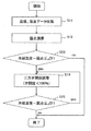
- FIG. 3 is a flowchart of the condensation avoidance operation control of this embodiment.
- the control device 10 collects measurement data of various sensors etc. as needed (at predetermined time intervals).
- the control device 10 is measured by the temperature data of the suction warm air measured by the thermometer 21 and the hygrometer 22, the humidity data, and the thermometer 26.
- the temperature data of the refrigerant at the inlet of the evaporator 6 is collected (step S11).
- control device 10 or the arithmetic communication device 23 to which the collected data is transferred from the control device 10 or the control device 17 to which the collected data is transferred via the arithmetic communication device 23 performs the processing described below.
- the control device 17 executes processing. Therefore, in this case, the control device 10 merely performs processing for collecting temperature data and the like and transmitting the data to the control device 17 via the arithmetic communication device 23 (and the arithmetic communication device 23 simply performs communication)
- the control device 17 executes the adjustment control itself of the three-way valve 24 in steps S14 and S15 described later.
- step S12 described later may be executed by the control device 10 or the arithmetic communication device 23.
- the calculated dew point temperature is transmitted to the control device 17 together with the collected refrigerant temperature.
- the control device 17 executes the process after S13.
- the control device 10 or the arithmetic communication device 23 transmits the latest dew point temperature and refrigerant temperature data to the control device 17 at any time during the process of steps S14 and S15.
- the control device 10 or the arithmetic communication device 23 may execute the processes of steps S12 and S13 described later.
- control device 10 and the arithmetic communication device 23 will be described simply as transmitting collected data to the control device 17.
- control device 17 acquires the collected data (temperature data of suction warm air, humidity data, and temperature data of refrigerant at the inlet of the evaporator 6) as needed.
- the dew point temperature of the suction warm air is calculated based on the acquired suction warm air temperature data and humidity data (step S12), and is there a possibility of dew condensation occurrence based on the dew point temperature and the refrigerant temperature? It is determined whether or not the possibility of dew condensation is high (step S13).
- step S13 is to determine whether or not “refrigerant temperature ⁇ dew point temperature ⁇ ⁇ T1 ( ⁇ T1; predetermined temperature difference set in advance)”. That is, it is determined whether or not the temperature difference between the refrigerant temperature and the dew point temperature is less than or equal to a predetermined value set in advance. If the temperature difference is less than or equal to the predetermined value (YES in step S13), condensation may occur. It is determined that If there is no possibility of occurrence of condensation (step S13, NO), this process ends.
- step S13 The determination method itself in step S13 may be an existing technology and will not be described in detail, and ⁇ T1 may be appropriately determined by a designer or the like, but will be briefly described below.
- the dew point temperature is lower than the refrigerant temperature, and the temperature difference can be increased by raising the refrigerant temperature.
- the temperature difference between the refrigerant temperature and the dew point temperature decreases, the possibility of dewing increases.
- the above ⁇ T 1 is set to a value which is considered that condensation may occur if the temperature difference becomes smaller, although condensation has not yet occurred, as an example (a person judges based on common general knowledge in the relevant technical field) To set).
- step S14 the valve opening degree adjustment control of the three-way valve 24 is performed (step S14).
- the valve on the short circuit tube 29 side in the three-way valve 24 is normally closed (100%, distributed to the cold heat source 20 side), and the determination in step S13 is YES.
- the valve on the short circuit tube 29 side of the three-way valve 24 is opened by a predetermined amount (here, for example, the valve opening degree is + 10%).
- the valve opening degree of the cold heat source 20 side valve in the three-way valve 24 may also be interlocked (here, for example, the valve opening degree is set to -10%).
- step S15 based on the next collected data, it is judged again whether there is the possibility of the occurrence of condensation.
- the process of step S15 is the same as the process of steps S12 and S13 above, and the dew point temperature is first calculated based on the collected data, and whether condensation may occur or not based on the dew point temperature and the refrigerant temperature To determine the
- step S14 is repeated until the determination of step S15 is NO, that is, it is determined that condensation is not likely to occur.
- the valve opening degree of the short circuit tube 29 in the three-way valve 24 is increased by 10% (10% ⁇ 20% ⁇ 30% ⁇ ). That is, the temperature of the cold water flowing into the condenser 12 is gradually increased by gradually increasing the proportion (quantity) of the hot water directly sent to the delivery pipe 27 through the shorting pipe 29 among the hot water returned from the condenser 12 (The temperature of the mixture of the cold water from the cold heat source 20 and the hot water from the three-way valve 24) is gradually raised. As a result, naturally, the temperature of the refrigerant output from the condenser 12 also gradually increases, and this refrigerant is sent to the evaporator 6 by the refrigerant supply device 16.
- the refrigerant temperature in the above judgment formula “refrigerant temperature ⁇ dew point temperature ⁇ ⁇ T1” gradually increases, and the temperature difference with the dew point temperature increases, so either is “refrigerant temperature ⁇ dew point temperature > [Delta] T1 ”(the determination in step S15 is NO). That is, the occurrence of condensation can be avoided.
- step S12 is the existing technology as already described above, if it is briefly explained here once, as shown in FIG. Is calculated (step S21), and the partial pressure of water vapor is calculated based on the humidity data (step S22), and the dew point temperature is calculated based on this (step S23).
- step S21 the partial pressure of water vapor is calculated based on the humidity data
- step S23 the dew point temperature is calculated based on this.
- the specific calculation formulas and the like of the processes in steps S21, S22, and S23 are general ones, and thus will not be particularly described here.
- step S15 the determination in step S15 is performed each time (every time the valve opening is decreased).
- step S15 determines whether condensation is likely to occur. If the determination in step S15 is YES, that is, if it is determined that condensation is likely to occur, the processing in steps S14 and S15 of FIG. 3 is performed again so that it is determined that condensation is not likely to occur again. Execute three-way valve opening adjustment processing.
- condensation can be avoided by adjusting and controlling the three-way valve 24 configured as described above.
- the temperature of the coolant (such as cold water) supplied to the condenser 12 of the cold heat source unit 18 is raised by adjusting the valve opening of the three-way valve 24 Since condensation can be avoided by raising the temperature of the refrigerant flowing into the cooling circuit 7 (or reducing the flow rate (heat exchange flow rate)), the pump rotational speed of the refrigerant supply device 16 and the discharge of the cold heat source 20 can be avoided. Condensation can be avoided without the need to adjust the amount of force, and problems such as pump stop and refrigerator stop do not occur, and highly reliable condensation avoidance cooling operation can be performed.
Landscapes
- Engineering & Computer Science (AREA)
- Chemical & Material Sciences (AREA)
- Combustion & Propulsion (AREA)
- Mechanical Engineering (AREA)
- General Engineering & Computer Science (AREA)
- Other Air-Conditioning Systems (AREA)
- Air Conditioning Control Device (AREA)
Abstract
流入暖気を冷却する蒸発器6から戻される蒸発冷媒を冷熱源20から送出管27を介して送られてくる冷却液により冷却する凝縮器12から、冷却液(温水等)が戻り管28を介して冷熱源20に戻される構成において、この戻り管28の途中に三方弁24を設け、冷却液(温水等)の一部を直接、送出管27に送出可能な構成とする。そして、結露発生可能性ありの判定が行われた場合、制御装置17が三方弁24の弁開度を制御して、冷却液(温水等)の一部を直接、送出管27に流入させることで、凝縮器12に流入する冷却液の温度を上昇させ、以って蒸発器6への冷媒の温度を上昇させることで、結露回避する。
Description
本発明は、局所冷却システムに係わり、特にその局所冷却ユニットにおける結露防止制御に関する。
例えば多数の電算機を収容している電算機室(サーバルーム等)のような発熱密度が高い空間を冷却する為の空調システムに関しては、例えば特許文献1等に開示されている空調システムが知られている。この特許文献1では、高発熱、大風量に起因するラック毎の局所的な高温発生問題を解決できる空調システムが提案されている。
また、特許文献1には、結露防止制御方法が開示されている。
あるいは、複数の局所空調装置を室内の各所(各電算機収納ラックの上方等)に配置して、各局所空調装置がそれぞれ比較的狭いエリア内の冷却を行う局所空調システムが知られている。
特開2006-162248号公報
上記特許文献1における従来の結露防止制御方法では、露点温度と冷媒温度との温度差に基づいて、冷媒圧送装置や冷熱源の出力量を調整することで結露回避を行っている。しかし、この様な方法では、冷媒圧送装置の冷媒ポンプ回転数を下げるとモータ始動トルク不足によるポンプ停止が発生する可能性があり、同様に冷熱源の冷凍機出力を下げると(コンプレッサーの回転数を下げると)コンプレッサー始動トルク不足による冷凍機停止が発生する可能性がある。
また、上記のような電算機室において局所的な冷却に用いられる局所空調装置は、特に電算機を収容するラック等の上方に設置される場合、結露が発生すると、その水滴が下に落ちて電算機を濡らし、電算機を故障させる等の重大事故に繋がる可能性がある。よって、上記ポンプ停止等の事態が生じることなく確実に結露発生を防止できる、信頼性の高い結露回避制御が行えることが望まれている。
本発明の課題は、冷媒ポンプ停止や冷凍機停止等が発生する可能性なく、信頼性が高い結露回避冷却運転が行える局所冷却システムを提供することである。
本発明の局所冷却システムは、流入暖気を冷却して局所エリアに送出する局所冷却ユニットと、該局所冷却ユニットに第1の冷媒を供給する冷熱源ユニットと、該冷熱源ユニットに第2の冷媒を供給する冷却回路を有し、前記冷熱源ユニットは、前記局所冷却ユニットから戻される前記第1の冷媒を前記第2の冷媒により冷却する凝縮器、該凝縮器により冷却された前記第1の冷媒を前記局所冷却ユニットへ送出する冷媒供給装置を有し、前記冷却回路は、前記凝縮器へ送出管を介して前記第2の冷媒を送出し、前記凝縮器から戻り管を介して前記第2の冷媒を還流する冷熱源を有し、前記局所冷却ユニットは、前記冷媒供給装置によって送られてくる前記第1の冷媒により前記流入暖気を冷却する蒸発器を有する空調システムにおいて、前記流入暖気の露点温度を計測する露点温度計測手段と、前記蒸発器に流入する前記第1の冷媒の温度を計測する冷媒温度計測手段と、前記露点温度と前記第1の冷媒温度との温度差に基づいて、結露発生可能性ありか否かを判定する結露発生判定手段と、前記凝縮器から戻される前記第2の冷媒の一部を前記冷熱源を介さずに前記送出管に送出させる弁装置と、前記結露発生判定手段により結露発生可能性ありと判定された場合、前記弁装置を制御して、前記凝縮器から戻される前記第2の冷媒の一部を前記冷熱源を介さずに前記送出管に送出させることで、前記凝縮器に流入する前記第2の冷媒温度を上昇させる弁装置制御手段とを有する。
凝縮器から戻される第2の冷媒の温度は、当然、凝縮器に流入する第2の冷媒の温度よりも高い。よって、結露発生可能性がある場合には、三方弁を制御することで凝縮器から戻される第2の冷媒の一部を送出管へ送って冷熱源からの第2の冷媒と混合させることで、凝縮器に流入する第2の冷媒の温度を上昇させることができる。第2の冷媒の温度が上昇すれば、局所冷却ユニットへ供給する第1の冷媒の温度も上昇し、例えば第2の冷媒の温度を徐々に上昇させていけばいずれは結露発生可能性なしの判定が行われ、結露発生を回避できる。
以下、図面を参照して本発明の実施の形態について説明する。
図1には、本例の局所冷却システムを含む全体構成の断面図を示す。
図1において、例えば多数の電算機を収容している電算機室等のような発熱密度が高い任意の室内空間25において、複数列の機器収納用ラック1が設けられている。各機器収納用ラック1には電子機器等が収容されている。ここでは2列の機器収納用ラック1a,1bを示すが、この例に限らない。
各機器収納用ラック1の上方には冷却ユニット2(局所冷却装置;局所空調装置)が設けられている。ここでは2つの冷却ユニット2のみ示すが、冷却ユニット2は上記室内空間25内の各所(特に各機器収納用ラック1の上方)に設けられている。
冷却ユニット2の基本構成自体は、従来と略同様であってよく、ここでは特に詳細には説明しないが、蒸発器6、送風装置9等を有する構成である。蒸発器6には、例えば各冷却ユニット2に共通の冷熱源ユニット18から送出される冷媒が、配管を介して流入される。冷却ユニット2に流入する暖気は、この蒸発器6によって冷却され、この冷却空気(冷気)が送風装置9によって所定の冷却対象局所空間(例えば機器収納用ラック1aと1bの間の空間)へと送出される。
尚、上記の通り、一台の冷熱源ユニット18が、複数台の冷却ユニット2に冷媒を供給する構成であってもよいが、この例に限らず、各冷却ユニット2それぞれに対応する冷熱源ユニット18があってもよい。つまり一台の冷熱源ユニット18が、一台の冷却ユニット2に対してのみ冷媒を供給する構成であってもよい。
図2に、本例の局所冷却システムの詳細構成図を示す。これは主に上記冷却ユニット2及び冷熱源ユニット18の詳細構成を示すが、これらの詳細構成は基本的には従来と略同様であってよい。
ここで、図1には示していないが、局所冷却システムには、冷熱源ユニット18に対して冷媒を供給する為の構成として図2に示す冷却回路11が存在している。冷熱源ユニット18に対して冷媒(例えば、冷却液や冷水等)を供給する為の構成自体は、従来から存在するが、従来と異なる本システムの特徴は、主に図2に示す構成の冷却回路11を設けたこと(特に三方弁24を設けたこと)、及びこの三方弁24の制御処理にあり、これによって、冷媒供給装置16(例えば、冷媒ポンプ)や冷熱源20の出力量を調整することなく(よって、冷媒ポンプ停止や冷凍機停止等が発生することなく)、図示の冷却回路7(特に蒸発器6)における結露発生を回避するものである。
尚、蒸発器6に供給される冷媒との混同を避ける為、本説明では、上記冷却回路11における冷媒(冷熱源20から凝縮器12に供給する冷媒)を、冷却液(冷水等)であるものとして説明するが、これは一例であり、この例に限らない。また、蒸発器6に供給される冷媒が、冷却液(冷水等)であっても構わない。
この様に、三方弁24を設け、その制御によって結露発生を回避できるので、従来のようにモータ始動トルク不足によるポンプ停止や、コンプレッサー始動トルク不足による冷凍機停止が発生することはなく、信頼性が高い結露回避冷却運転を行うことができる。なお、ここでは一例として三方弁24を用いているが、流量を分岐(或いは混合)させ且つ流量を制御できる機構であればよく、例えばコックや制御弁の付いた二又管を複数個組み合わせて構成しても構わない。この様なものを総称して弁装置と呼ぶものとする。そして、本説明では、弁装置の一例である三方弁24を例にして説明する。
以下、上記冷却ユニット2、冷熱源ユニット18、冷却回路11の詳細構成・動作について説明するが、従来と略同様の構成・動作については簡単に説明するものとする。尚、図示の各種矢印(太線、実線、点線)のうち、太線の矢印は空気の流れを示し、点線の矢印は信号線を示し、実線の矢印は冷媒や冷却液の流れ(及び冷媒等が流れる配管)を示す。
以下、冷却ユニット2の詳細構成・動作について説明する。
まず、従来と略同様の構成について簡単に説明するならば、冷却ユニット2は、上記電子機器等の発熱体を有する機器収納用ラック1の背面側から排出される暖気を、吸込口3とエアフィルター4を通じて吸引し、この暖気が蒸発器6や膨張弁5等から構成された冷却回路7(図上、1点鎖線で囲む部分)により冷却された冷気を、送風装置9と吹出口8を介して、ラック1正面側に送風することで発熱体を冷却するものである。尚、一般的なことであるが、蒸発器6には上記冷熱源ユニット18から送られてくる冷媒が膨張弁5を介して流入し、この冷媒を蒸発器6内で蒸発させて蒸発潜熱を周囲から吸収することで周囲を冷却し、蒸発冷媒は冷熱源ユニット18に戻される。図上、膨張弁5の右横に示すバルブ状のものは、電磁弁であり、冷媒はこの電磁弁を介して蒸発器6に流入するが、ここでは特に関係ない。
ここで、冷却ユニット2は更に、制御装置10と演算通信装置23を備える。制御装置10は、例えばマイコン等であり、予め記憶されている所定のアプリケーションプログラムを実行することにより、既存の一般的な各種制御(例えば膨張弁5の弁開度や送風装置9の送風量の制御等)を実行し、更に後述する本手法の露点回避に係わる処理の一部を実行するものであってもよい。
また、演算通信装置23は、基本的には外部との通信を行う機能部あり、図示の例では制御装置17と通信線(点線で示す)を介して通信を行う。また、演算通信装置23は、例えば不図示のMPU等を有し、後述する本手法の露点回避に係わる処理の一部を実行するものであってもよいが、この処理は制御装置10が行っても良く、その場合には演算通信装置23は(演算処理を行わない)単なる通信装置であってもよい。詳しくは後述する。
また、冷却ユニット2には更に、ユニット2内の各所の温度を測定する温度計(図上、“TC”で示す)や、湿度を測定する湿度計(図上、“MC”で示す)が備えられており、各温度計/湿度計と上記制御装置10とは通信線(点線で示す)で接続されており、制御装置10は各温度計/湿度計で測定された温度データ/湿度データを随時収集している。
ここで、上記各温度計/湿度計のうち、特に本制御に関係のあるものについては参照番号を付してあり、参照番号を付したものだけ説明し、他については説明しないものとする。すなわち、まず、エアフィルタ4と蒸発器6の間の暖気吸入経路上に(蒸発器6の上流に)、温度計21と湿度計22を設けてある。これらは吸入暖気の露点温度を求める為のものである。よって、温度計21と湿度計22の代わりに露点温度計を設けてもよい。
本例では、制御装置10が、温度計21と湿度計22によって計測された温度データ及び湿度データに基づいて、これら温度計21、湿度計22の設置箇所の(吸入暖気の)露点温度を算出する。露点温度の算出式は、よく知られているものなので、ここでは特に説明しない。また、露点温度計を用いる場合には、制御装置10は単に露点温度計で計測された露点温度データを取得するだけである。
また、図示の温度計26は、例えば、蒸発器6に流入する直前の(蒸発器入口の)冷媒の温度を計測する為の温度計である。但し、この例に限らず、例えば蒸発器6の表面温度等を計測するものであってもよい(本説明では、この場合も、計測温度を冷媒温度とみなす)。
上記露点温度及び冷媒温度に基いて上記三方弁24の制御処理する。これは、後にフローチャート図を参照して説明する。
以下、図示の制御装置17、冷熱源ユニット18、冷却回路11等について説明する。
制御装置17は、図1には示していないが、本例の局所冷却システム全体を制御する装置であり、冷却ユニット2、冷熱源ユニット18、冷却回路11等を制御する。制御装置17は、マイコン等を有し、予め記憶されている所定のアプリケーションプログラムをCPUが実行することで各種制御を行う。尚、従来より行われている一般的な各種制御に関しては、ここでは特に説明しない。本手法に係わる制御についてのみ説明する。
尚、制御装置17は、指令装置19からの何らかの指示に応じた制御を行う場合もある。例えば、指令装置19は、制御装置17に、冷却ユニット2の送風量と冷風温度を指示する。制御装置17は、この指示に応じて、各種制御動作を行う(上記の通り、既存の一般的な制御であり、ここでは特に説明しない)。
制御装置17は、上記従来の制御処理機能に加えて、更に後述する三方弁24の弁開度の制御処理機能を有するという特徴を有する。既に述べた通り、この特徴部分以外は従来と略同様であってよい。
また、冷熱源ユニット18は、上記の通り従来と同じであってよく、簡単に説明するならば、凝縮器12、受液器13、冷媒供給装置16を有し、また各所に温度計(図上“TC”で示す)を設けており、また冷媒供給装置16から出力される冷媒の流量を計測する流量計(図上“QC”で示す)を設けており、制御装置17はこの温度データ、流量データ等に基づいて例えば冷媒供給装置16等を制御する。あるいは、各冷却ユニット2に指令を出す。
凝縮器12には上記蒸発器6からの蒸発冷媒が流入し、これを冷却・液化して冷媒に戻す。この冷媒は、一旦、受液器13に貯留した後、冷媒供給装置16によって冷却ユニット2側に送り出されて、蒸発器6に流入する。
凝縮器12には、冷却回路11(図上、1点鎖線で囲む部分;尚、冷熱源20が含まれてもよい)から冷却液が供給されている。すなわち、凝縮器12には冷熱源20からの冷却液(例えば冷水等)が送出管27を介して送られてきて、この冷水によって上記蒸発冷媒の冷却・液化が行われる。これによって蒸発冷媒が冷却される一方で冷水は温められる(これを温水と呼ぶものとする)。この温水は戻り管28を介して冷熱源20に戻され、冷熱源20によって冷却されることで再び冷水となって送出管27に送出される。
但し、本システムでは戻り管28の途中に三方弁24を設けている。
以下、この三方弁24に係わる構成、及び三方弁24の制御処理について詳しく説明する。
まず、本例の三方弁24は、1方向からの流入口と2方向への流出口とを具えるタイプ(管路を分流させるタイプ)である。既に述べた通り三方弁24は戻り管28の途中に設けられおり、流入口は凝縮器12側の戻り管28に接続しており、2方向への流出口は、一方は冷熱源20側の戻り管28(ここでは図示の通り戻り管28’と記すものとする)に接続し、他方は図示の短絡管29に接続している。短絡管29の他方は、送出管27に接続している。つまり、短絡管29を介して送出管27に直接、温水等を流出可能な構造となっている。
三方弁24の上記2方向への流出口それぞれには、当然、弁が設けられており、制御装置17が、これら各弁の弁開度を調整制御できる構成となっている。
このような三方弁24を設けたことにより、凝縮器12側から戻される上記温水を、冷熱源20側と送出管27側に分配することができる。分配比率は制御装置17の制御によって自由に調整できる。すなわち、凝縮器12側から戻される上記温水を100%冷熱源20側に送ることも、100%送出管27側に送ることも、あるいは例えば50%対50%や、30%対70%等、自由に調整することができる。
冷熱源20側への分配比率を100%にした場合は、従来と同じであり、凝縮器12から戻される温水の全ては、冷熱源20に流入されて冷却されて、送出管27を介して凝縮器12に送られる。一方、冷熱源20側への分配比率が100%未満である場合(但し、0%にはしない)、凝縮器12から戻される温水の一部は、短絡管29を介してダイレクトに送出管27に送られる。つまり、この場合、凝縮器12に流入する冷水は、冷熱源20からの冷水と三方弁24からの温水との混合液となり、当然、冷熱源20側への分配比率が100%である場合に比べてその温度は高くなる。
つまり、上記構成では、三方弁24における分配比率を制御することにより(2つの流出口の各弁の弁開度を制御することにより)、凝縮器12に流入される冷水の温度を調整する(特に温度上昇させる)ことができ、この冷水によって冷却される冷媒の温度を調整する(特に温度上昇させる)ことができる。
なお、三方弁の設置位置は図2の例に限らず、例えば図5(b)のように設置しても構わない。この場合、三方弁24は、2方向からの流入口と1方向への流出口とを具えるタイプ(管路を合流させるタイプ)である。
図5(b)に示す例の場合、まず、戻り管28は途中で冷熱源20側の戻り管28’と短絡管29に分岐している。そして、三方弁24は送出管27の途中に設けられており、2つの流入口は、一方は冷熱源20側の送出管27に接続しており、他方は短絡管29に接続している。また、流出口は、凝縮器12側の送出管27に接続している。つまり、三方弁24において、短絡管29からの温水と冷熱源20からの冷水とを合流させて、この混合液を凝縮器12側へ流出可能な構造となっている。
図5(b)に示す例の三方弁24の上記2つの流入口それぞれには、弁が設けられており、制御装置17が、これら各弁の弁開度を調整制御できる構成となっている。この制御方法と作用は、上記図2に示す構成例と殆ど同様であり、例えば混合液の温度を上昇させたい場合には短絡管29側の弁の弁開度を増加させればよい。尚、短絡管29側の弁を完全に閉じた場合には、凝縮器12側から戻される温水は全て冷熱源20に流入し、凝縮器12には冷熱源20から送出される冷水のみが流入することになる。
尚、図5(a)には図2に示す冷却回路11の構成例の抜粋図を示す。
更に、三方弁自体の設置箇所は図5(a)または図5(b)と同じだが、その制御方法が異なる例を、図5(c)、図5(d)に示し、以下に説明する。
図1(図5(a))や図5(b)の三方弁24の制御方法は、凝縮器12から戻る冷却液(温水)の一部を冷熱源20を介さずに凝縮器12に還流する。これに対し、図5(c)や図5(d)の三方弁24の制御方法は、冷熱源20から送出する冷却液の一部を凝縮器12に送らずに冷熱源20に還流する。つまり、冷熱源20の出力(コンプレッサーの回転数)を変えなくても(減少させなくても)、凝縮器12への冷却液の流入量を変える(減少させる)ことができる。
まず、図5(c)の例について説明する。
この例では三方弁24の設置位置は図5(a)の例と同じであるが、その構成は図5(b)の例と同じである。すなわち、本例の三方弁24の設置位置は戻り管28の途中であり、その構成は2方向からの流入口と1方向への流出口とを具えるタイプ(管路を合流させるタイプ)である。
そして、2つの流入口の一方は凝縮器12側の戻り管28に接続しており、他方は短絡管29に接続している。尚、短絡管29における液の流れる方向が図5(a)や図5(b)とは逆になることから、図示のように短絡管29’と記すものとする。これは後述する図5(d)についても同様である。また、1つの流出口は冷熱源20側の戻り管28’に接続している。また、この例では、送出管27は途中で凝縮器12側の送出管27と短絡管29’とに分岐している。
上記構成において、三方弁24において少なくとも短絡管29’に接続した流入口には、弁が設けられており、制御装置17が、この弁の弁開度を調整制御できる構成となっている。この弁を完全に閉じた状態では、冷熱源20から送出される冷却液は100%凝縮器12に流入する。
一方、この弁が開いた状態では、その弁開度に応じて、冷熱源20から送出される冷却液の一部が、三方弁24と戻り管28’を介して、冷熱源20に戻される。換言すれば、冷熱源20から送出される冷却液は、100%凝縮器12に流入するのではなく、その一部が凝縮器12に流入することになる。つまり、冷熱源20の出力(コンプレッサーの回転数)を減少させなくても、凝縮器12への冷却液の流入量を減少させることができる。これによって、図5(a)、(b)の例のように、凝縮器12への冷却液の温度を上昇させる場合と同様の効果が得られる。つまり、凝縮器12における冷却性能が低下し、蒸発器6への冷媒の温度を上昇させることができる。
次に、図5(d)の例について説明する。
この例では三方弁24の設置位置は図5(b)の例と同じであるが、その構成は図5(a)の例と同じである。すなわち、本例の三方弁24の設置位置は送出管27の途中であり、その構成は2方向への流出口と1方向からの流入口とを具えるタイプ(管路を分流させるタイプ)である。
本例では、三方弁24は送出管27の途中に設けられおり、2つの流出口は、一方は凝縮器12側の送出管27に接続しており、他方は短絡管29’に接続している。短絡管29’の他方は、戻り管28に接続している。また、三方弁24の流入口は、冷熱源20側の送出管27に接続している。
上記構成において、三方弁24において少なくとも短絡管29’に接続した流入口には、弁が設けられており、制御装置17が、この弁の弁開度を調整制御できる構成となっている。この弁を完全に閉じた状態では、冷熱源20から送出される冷却液は100%凝縮器12に流入する。
一方、この弁が開いた状態では、その弁開度に応じて、冷熱源20から送出される冷却液の一部が、三方弁24、短絡管29’、戻り管28’を介して、冷熱源20に戻される。換言すれば、冷熱源20から送出される冷却液は、100%凝縮器12に流入するのではなく、その一部が凝縮器12に流入することになる。つまり、冷熱源20の出力(コンプレッサーの回転数)を減少させなくても、凝縮器12への冷却液の流入量を減少させることができる。これによって、上記図5(c)の場合と同様の効果が得られる。
以上説明したように、冷却回路11を、図5(c)や図5(d)に示す構成とすることにより、凝縮器12に流入する冷却液の流量を減らす調整が可能になり、冷熱源20の出力(コンプレッサーの回転数)の制御を行うことなく凝縮器12における冷却能力の調整を行うことが可能である。
この三方弁24における分配比率の制御処理について、以下、図3を参照して説明する。
図3は、本例の結露回避運転制御のフローチャート図である。
図3に示すように、まず上記の通り制御装置10は随時(所定時間間隔で)、各種センサ等の計測データを収集している。ここでは、本手法に関係のあるデータに限って説明するので、制御装置10は、温度計21、湿度計22で計測される吸入暖気の温度データ、湿度データ、及び温度計26で計測される蒸発器6入口での冷媒の温度データを収集している(ステップS11)。
そして、制御装置10、または制御装置10から上記収集データを渡された演算通信装置23、あるいは演算通信装置23を介して上記収集データを渡された制御装置17は、以下に説明する処理を行う。尚、以下の説明では、制御装置17が処理実行する例について説明する。よって、この場合には、制御装置10は単に温度データ等を収集してこれを演算通信装置23を介して制御装置17に送信する処理を行うだけである(また、演算通信装置23は単なる通信装置となる)が、勿論、この例に限るものではない。但し、他の例においても、後述するステップS14,S15の三方弁24の調整制御自体は、制御装置17が実行することになる。
すなわち、例えば、後述するステップS12の処理は、制御装置10または演算通信装置23が実行してもよく、この場合には算出した露点温度を、収集した冷媒温度と共に制御装置17に送信し、ステップS13以降の処理は制御装置17が実行する。勿論、この場合には、ステップS14,S15の処理実行中に、制御装置10または演算通信装置23は、随時、最新の露点温度と冷媒温度データを、制御装置17に送信している。あるいは、例えば、後述するステップS12とS13の処理を、制御装置10または演算通信装置23が実行してもよい。
但し、以下の説明では、上記の通り、制御装置10、演算通信装置23は、単に収集データを制御装置17に送信するものとして説明する。
この例では、制御装置17は、随時、上記収集データ(吸入暖気の温度データ、湿度データ、及び蒸発器6入口での冷媒の温度データ)を取得することになる。
そして、取得した上記吸入暖気の温度データ、湿度データに基づいて、吸入暖気の露点温度を算出し(ステップS12)、この露点温度と上記冷媒温度とに基づいて、結露発生の可能性があるか否か(結露発生可能性が高いか否か)を判定する(ステップS13)。
ステップS13の処理は、「冷媒温度-露点温度≦ΔT1(ΔT1;予め設定される、所定の温度差)」か否かを判定するものである。すなわち、冷媒温度と露点温度との温度差が、予め設定される所定値以下となったか否かを判定し、所定値以下となった場合には(ステップS13,YES)、結露発生可能性ありと判定するものである。結露発生可能性無しであれば(ステップS13,NO)、本処理は終了する。
尚、ステップS13の判定手法自体は、既存技術であってよく、特に詳細には説明しないし、ΔT1は設計者等が適宜決定してよいものであるが、以下、簡単に説明する。
通常、露点温度は、冷媒温度よりも低いものであり、冷媒温度を上昇させることで上記温度差を大きくすることができる。また、よく知られているように、極端に言えば、冷媒温度-露点温度=0(温度差なし)となると、ほぼ間違いなく結露が発生する。冷媒温度と露点温度との温度差が小さくなると、結露発生の可能性が高まることになる。上記ΔT1は、例えば一例としては、未だ結露発生していないが、これ以上温度差が小さくなると結露が発生し得ると考えられる値に設定する(人間が当該技術分野の一般常識に基づいて判断して設定する)。
そして、結露発生可能性ありと判定した場合には(ステップS13,YES)、三方弁24の弁開度調整制御を行う(ステップS14)。これは、例えば、通常時は、三方弁24における短絡管29側の弁は閉じているものとし(100%、冷熱源20側へ分配している)、ステップS13の判定がYESとなった場合には、三方弁24における短絡管29側の弁を所定量開く(ここでは、例えば弁開度を+10%とする)。尚、その際、三方弁24における冷熱源20側の弁の弁開度も、連動制御してもよい(ここでは、例えば弁開度を-10%とする)。
そして、次の収集データに基づいて、再び結露発生の可能性があるか否かの判定を行う(ステップS15)。このステップS15の処理は、上記ステップS12,S13の処理と同様であり、収集データに基づいて、まず露点温度を算出し、この露点温度と冷媒温度とに基づいて、結露発生可能性ありか否かを判定するものである。
そして、ステップS15の判定がNOとなるまで、つまり結露発生可能性無しと判定されるまで、上記ステップS14の処理を繰り返すことになる。上記の例では、三方弁24における短絡管29側の弁開度を10%ずつ増加していく(10%→20%→30%→・・・)ことになる。つまり、凝縮器12から戻される温水のうち短絡管29を介してダイレクトに送出管27に送られる温水の割合(量)を少しずつ増やしていくことで、凝縮器12に流入される冷水の温度(冷熱源20からの冷水と三方弁24からの温水との混合液の温度)を、徐々に高くしていく。これによって、当然、凝縮器12から出力される冷媒の温度も徐々に高くなっていき、この冷媒が冷媒供給装置16により蒸発器6に送られる。
これによって、当然、上記の判定式「冷媒温度-露点温度≦ΔT1」における冷媒温度は徐々に高くなっていき、露点温度との温度差が大きくなっていくので、何れは“冷媒温度-露点温度>ΔT1”となることになる(ステップS15の判定がNOとなる)。つまり、結露発生を回避できる。
尚、ステップS12の露点温度演算に関しては、既に述べた通り既存技術であるが、ここで一応概略的に説明しておくならば、図4に示すように、まず温度データに基づいて飽和水蒸気圧を算出し(ステップS21)、更に湿度データに基づいて水蒸気分圧を算出し(ステップS22)、これに基づいて露点温度を算出する(ステップS23)。ステップS21,S22,S23の各処理の具体的な算出式等については、一般的なものであるので、ここでは特に説明しない。
また、図3の処理によって凝縮器12に流入される冷水の温度を上昇させた後、例えば一定時間経過後に、再び冷水温度を下げる処理を行っても良い。この処理については特に説明しないが、例えば、ステップS14の処理とは逆の三方弁開度調整処理を行い(例えば、現在、三方弁24における短絡管29側の弁開度が50%であったなら、これを40%→30%→20%・・・等と順次減少させていく)、その都度(弁開度を減少させる毎に)ステップS15の判定を行う。そして、ステップS15の判定がYESとなったら、つまり、結露発生可能性ありと判定されたら、再び図3のステップS14,S15の処理を行って、再び結露発生可能性無しと判定されるように三方弁開度調整処理を実行する。
以上説明したように、本手法では、上記構成の三方弁24を調整・制御することで、結露回避を行うことができる。
つまり、本手法では、結露発生可能性ありと判定した場合には、三方弁24の弁開度調整によって、冷熱源ユニット18の凝縮器12に供給する冷却液(冷水等)の温度を上昇させる(または流量(熱交換流量)を減少させる)ことにより、冷却回路7に流入する冷媒の温度を上昇させることで、結露回避ができるので、冷媒供給装置16のポンプ回転数や冷熱源20の出力量を調整する必要なく、結露回避を行うことができ、ポンプ停止や冷凍機停止等の問題が生じることはなく、信頼性が高い結露回避冷却運転が可能となる。
本発明の局所冷却システムによれば、ポンプ停止や冷凍機停止等が発生する可能性がなく、信頼性が高い結露回避冷却運転が行える。
Claims (4)
- 流入暖気を冷却して局所エリアに送出する局所冷却ユニットと、該局所冷却ユニットに第1の冷媒を供給する冷熱源ユニットと、該冷熱源ユニットに第2の冷媒を供給する冷却回路を有し、
前記冷熱源ユニットは、前記局所冷却ユニットから戻される前記第1の冷媒を前記第2の冷媒により冷却する凝縮器、該凝縮器により冷却された前記第1の冷媒を前記局所冷却ユニットへ送出する冷媒供給装置を有し、
前記冷却回路は、前記凝縮器へ送出管を介して前記第2の冷媒を送出し、前記凝縮器から戻り管を介して前記第2の冷媒を還流する冷熱源を有し、
前記局所冷却ユニットは、前記冷媒供給装置によって送られてくる前記第1の冷媒により前記流入暖気を冷却する蒸発器を有する空調システムにおいて、
前記流入暖気の露点温度を計測する露点温度計測手段と、
前記蒸発器に流入する前記第1の冷媒の温度を計測する冷媒温度計測手段と、
前記露点温度と前記第1の冷媒温度との温度差に基づいて、結露発生可能性ありか否かを判定する結露発生判定手段と、
前記凝縮器から戻される前記第2の冷媒の一部を前記冷熱源を介さずに前記送出管に送出させる弁装置と、
前記結露発生判定手段により結露発生可能性ありと判定された場合、前記弁装置を制御して、前記凝縮器から戻される前記第2の冷媒の一部を前記冷熱源を介さずに前記送出管に送出させることで、前記凝縮器に流入する前記第2の冷媒温度を上昇させる弁装置制御手段と、
を有することを特徴とする局所冷却システム。 - 前記弁装置制御手段は、
前記結露発生判定手段により結露発生可能性なしの判定が行われるまで、前記弁装置の弁開度を所定の割合で徐々に増加させることにより、前記冷熱源を介さずに前記第2の冷媒を前記送出管に送出させる流量を増加させることを特徴とする請求項1記載の局所冷却システム。 - 流入暖気を冷却して局所エリアに送出する局所冷却ユニットと、該局所冷却ユニットに第1の冷媒を供給する冷熱源ユニットと、該冷熱源ユニットに第2の冷媒を供給する冷却回路を有し、
前記冷熱源ユニットは、前記局所冷却ユニットから戻される前記第1の冷媒を前記第2の冷媒により冷却する凝縮器、該凝縮器により冷却された前記第1の冷媒を前記局所冷却ユニットへ送出する冷媒供給装置を有し、
前記冷却回路は、前記凝縮器へ送出管を介して前記第2の冷媒を送出し、前記凝縮器から戻り管を介して前記第2の冷媒を還流する冷熱源を有し、
前記局所冷却ユニットは、前記冷媒供給装置によって送られてくる前記第1の冷媒により前記流入暖気を冷却する蒸発器を有する空調システムにおいて、
前記流入暖気の露点温度を計測する露点温度計測手段と、
前記蒸発器に流入する前記第1の冷媒の温度を計測する冷媒温度計測手段と、
前記露点温度と前記第1の冷媒温度との温度差に基づいて、結露発生可能性ありか否かを判定する結露発生判定手段と、
前記冷熱源から送出される前記第2の冷媒の一部を前記凝縮器を介さずに前記冷熱源に還流させる弁装置と、
前記結露発生判定手段により結露発生可能性ありと判定された場合、前記弁装置を制御して、前記冷熱源から送出される前記第2の冷媒の一部を前記凝縮器を介さずに前記戻り管に還流させることで、前記凝縮器に流入する前記第2の冷媒の流量を減少させる弁装置制御手段と、
を有することを特徴とする局所冷却システム。 - 前記弁装置制御手段は、
前記結露発生判定手段により結露発生可能性なしの判定が行われるまで、前記弁装置の弁開度を所定の割合で徐々に増加させることにより、前記凝縮器を介さずに前記第2の冷媒を前記戻り管に還流させる流量を増加させることを特徴とする請求項3記載の局所冷却システム。
Priority Applications (2)
| Application Number | Priority Date | Filing Date | Title |
|---|---|---|---|
| CN2010800391255A CN102510982A (zh) | 2010-08-12 | 2010-08-12 | 局部冷却系统 |
| PCT/JP2010/063677 WO2012020493A1 (ja) | 2010-08-12 | 2010-08-12 | 局所冷却システム |
Applications Claiming Priority (1)
| Application Number | Priority Date | Filing Date | Title |
|---|---|---|---|
| PCT/JP2010/063677 WO2012020493A1 (ja) | 2010-08-12 | 2010-08-12 | 局所冷却システム |
Publications (1)
| Publication Number | Publication Date |
|---|---|
| WO2012020493A1 true WO2012020493A1 (ja) | 2012-02-16 |
Family
ID=45567471
Family Applications (1)
| Application Number | Title | Priority Date | Filing Date |
|---|---|---|---|
| PCT/JP2010/063677 Ceased WO2012020493A1 (ja) | 2010-08-12 | 2010-08-12 | 局所冷却システム |
Country Status (2)
| Country | Link |
|---|---|
| CN (1) | CN102510982A (ja) |
| WO (1) | WO2012020493A1 (ja) |
Citations (2)
| Publication number | Priority date | Publication date | Assignee | Title |
|---|---|---|---|---|
| JPH09166346A (ja) * | 1995-12-14 | 1997-06-24 | Takasago Thermal Eng Co Ltd | 空調機、空調システムおよびその制御方法 |
| JP2009036506A (ja) * | 2007-07-09 | 2009-02-19 | Ntt Facilities Inc | 空気調和システム及びその運転方法 |
Family Cites Families (3)
| Publication number | Priority date | Publication date | Assignee | Title |
|---|---|---|---|---|
| JP2000171079A (ja) * | 1998-12-07 | 2000-06-23 | Aisin Seiki Co Ltd | 輻射対流型冷暖房装置 |
| CN101545660B (zh) * | 2009-05-15 | 2010-11-10 | 何森 | 室内温度湿度的独立控制系统 |
| CN201488163U (zh) * | 2009-08-21 | 2010-05-26 | 张军 | 用于地板制冷系统中的露点控制装置 |
-
2010
- 2010-08-12 WO PCT/JP2010/063677 patent/WO2012020493A1/ja not_active Ceased
- 2010-08-12 CN CN2010800391255A patent/CN102510982A/zh active Pending
Patent Citations (2)
| Publication number | Priority date | Publication date | Assignee | Title |
|---|---|---|---|---|
| JPH09166346A (ja) * | 1995-12-14 | 1997-06-24 | Takasago Thermal Eng Co Ltd | 空調機、空調システムおよびその制御方法 |
| JP2009036506A (ja) * | 2007-07-09 | 2009-02-19 | Ntt Facilities Inc | 空気調和システム及びその運転方法 |
Also Published As
| Publication number | Publication date |
|---|---|
| CN102510982A (zh) | 2012-06-20 |
Similar Documents
| Publication | Publication Date | Title |
|---|---|---|
| US9696078B2 (en) | Refrigeration cycle apparatus | |
| EP3279589B1 (en) | Refrigeration device | |
| JP2010216765A (ja) | 局所冷却システム | |
| CN107461874B (zh) | 空调器融霜控制方法及空调器 | |
| JP5787604B2 (ja) | 車両用空気調和装置故障診断システム及び故障診断装置 | |
| CN102345949A (zh) | 一种多联式空调换热器冷媒流量调节系统及其调节方法 | |
| WO2010049999A1 (ja) | 空気調和装置 | |
| CN103154626B (zh) | 热源装置 | |
| CN103842736B (zh) | 制冷装置 | |
| JP6479181B2 (ja) | 空気調和装置 | |
| JP7656179B2 (ja) | 冷媒漏洩検知システム、方法、およびプログラム | |
| WO2012020495A1 (ja) | 局所空調システム、その制御装置、プログラム | |
| JP2010216776A (ja) | 局所空調システム、その制御装置、プログラム | |
| CN103075784A (zh) | 表面温度推定装置、表面温度推定方法以及结露判定装置 | |
| JP7069298B2 (ja) | 空気調和装置 | |
| JP4986701B2 (ja) | 冷媒流量の計測方法、冷凍装置の冷暖房能力を求める方法および冷媒流量計測装置 | |
| US12326284B2 (en) | Systems and methods for humidity control in an air conditioning system | |
| CN103890501A (zh) | 空气调节装置 | |
| JP3915819B2 (ja) | 空気調和装置 | |
| JP4839861B2 (ja) | 空気調和装置 | |
| CN116147102A (zh) | 管理装置和热源系统 | |
| CN110726225A (zh) | 多联机系统及其控制方法 | |
| JP6115079B2 (ja) | 局所空調システム | |
| JP6678837B1 (ja) | 空気調和装置および熱媒体流量算出方法 | |
| JP6921299B2 (ja) | 空気調和装置およびエアハンドリングユニット |
Legal Events
| Date | Code | Title | Description |
|---|---|---|---|
| WWE | Wipo information: entry into national phase |
Ref document number: 201080039125.5 Country of ref document: CN |
|
| 121 | Ep: the epo has been informed by wipo that ep was designated in this application |
Ref document number: 10855894 Country of ref document: EP Kind code of ref document: A1 |
|
| NENP | Non-entry into the national phase |
Ref country code: DE |
|
| 122 | Ep: pct application non-entry in european phase |
Ref document number: 10855894 Country of ref document: EP Kind code of ref document: A1 |
|
| NENP | Non-entry into the national phase |
Ref country code: JP |