WO2012018124A1 - 表示装置、表示方法 - Google Patents
表示装置、表示方法 Download PDFInfo
- Publication number
- WO2012018124A1 WO2012018124A1 PCT/JP2011/067979 JP2011067979W WO2012018124A1 WO 2012018124 A1 WO2012018124 A1 WO 2012018124A1 JP 2011067979 W JP2011067979 W JP 2011067979W WO 2012018124 A1 WO2012018124 A1 WO 2012018124A1
- Authority
- WO
- WIPO (PCT)
- Prior art keywords
- data
- row
- eye
- field data
- field
- Prior art date
- Legal status (The legal status is an assumption and is not a legal conclusion. Google has not performed a legal analysis and makes no representation as to the accuracy of the status listed.)
- Ceased
Links
Images











Classifications
-
- G—PHYSICS
- G02—OPTICS
- G02F—OPTICAL DEVICES OR ARRANGEMENTS FOR THE CONTROL OF LIGHT BY MODIFICATION OF THE OPTICAL PROPERTIES OF THE MEDIA OF THE ELEMENTS INVOLVED THEREIN; NON-LINEAR OPTICS; FREQUENCY-CHANGING OF LIGHT; OPTICAL LOGIC ELEMENTS; OPTICAL ANALOGUE/DIGITAL CONVERTERS
- G02F1/00—Devices or arrangements for the control of the intensity, colour, phase, polarisation or direction of light arriving from an independent light source, e.g. switching, gating or modulating; Non-linear optics
- G02F1/01—Devices or arrangements for the control of the intensity, colour, phase, polarisation or direction of light arriving from an independent light source, e.g. switching, gating or modulating; Non-linear optics for the control of the intensity, phase, polarisation or colour
- G02F1/13—Devices or arrangements for the control of the intensity, colour, phase, polarisation or direction of light arriving from an independent light source, e.g. switching, gating or modulating; Non-linear optics for the control of the intensity, phase, polarisation or colour based on liquid crystals, e.g. single liquid crystal display cells
-
- G—PHYSICS
- G09—EDUCATION; CRYPTOGRAPHY; DISPLAY; ADVERTISING; SEALS
- G09G—ARRANGEMENTS OR CIRCUITS FOR CONTROL OF INDICATING DEVICES USING STATIC MEANS TO PRESENT VARIABLE INFORMATION
- G09G3/00—Control arrangements or circuits, of interest only in connection with visual indicators other than cathode-ray tubes
- G09G3/001—Control arrangements or circuits, of interest only in connection with visual indicators other than cathode-ray tubes using specific devices not provided for in groups G09G3/02 - G09G3/36, e.g. using an intermediate record carrier such as a film slide; Projection systems; Display of non-alphanumerical information, solely or in combination with alphanumerical information, e.g. digital display on projected diapositive as background
- G09G3/003—Control arrangements or circuits, of interest only in connection with visual indicators other than cathode-ray tubes using specific devices not provided for in groups G09G3/02 - G09G3/36, e.g. using an intermediate record carrier such as a film slide; Projection systems; Display of non-alphanumerical information, solely or in combination with alphanumerical information, e.g. digital display on projected diapositive as background to produce spatial visual effects
-
- G—PHYSICS
- G09—EDUCATION; CRYPTOGRAPHY; DISPLAY; ADVERTISING; SEALS
- G09G—ARRANGEMENTS OR CIRCUITS FOR CONTROL OF INDICATING DEVICES USING STATIC MEANS TO PRESENT VARIABLE INFORMATION
- G09G3/00—Control arrangements or circuits, of interest only in connection with visual indicators other than cathode-ray tubes
- G09G3/20—Control arrangements or circuits, of interest only in connection with visual indicators other than cathode-ray tubes for presentation of an assembly of a number of characters, e.g. a page, by composing the assembly by combination of individual elements arranged in a matrix no fixed position being assigned to or needed to be assigned to the individual characters or partial characters
- G09G3/34—Control arrangements or circuits, of interest only in connection with visual indicators other than cathode-ray tubes for presentation of an assembly of a number of characters, e.g. a page, by composing the assembly by combination of individual elements arranged in a matrix no fixed position being assigned to or needed to be assigned to the individual characters or partial characters by control of light from an independent source
- G09G3/36—Control arrangements or circuits, of interest only in connection with visual indicators other than cathode-ray tubes for presentation of an assembly of a number of characters, e.g. a page, by composing the assembly by combination of individual elements arranged in a matrix no fixed position being assigned to or needed to be assigned to the individual characters or partial characters by control of light from an independent source using liquid crystals
- G09G3/3611—Control of matrices with row and column drivers
- G09G3/3648—Control of matrices with row and column drivers using an active matrix
-
- H—ELECTRICITY
- H04—ELECTRIC COMMUNICATION TECHNIQUE
- H04N—PICTORIAL COMMUNICATION, e.g. TELEVISION
- H04N13/00—Stereoscopic video systems; Multi-view video systems; Details thereof
- H04N13/30—Image reproducers
- H04N13/332—Displays for viewing with the aid of special glasses or head-mounted displays [HMD]
- H04N13/341—Displays for viewing with the aid of special glasses or head-mounted displays [HMD] using temporal multiplexing
-
- H—ELECTRICITY
- H04—ELECTRIC COMMUNICATION TECHNIQUE
- H04N—PICTORIAL COMMUNICATION, e.g. TELEVISION
- H04N13/00—Stereoscopic video systems; Multi-view video systems; Details thereof
- H04N13/30—Image reproducers
- H04N13/398—Synchronisation thereof; Control thereof
-
- G—PHYSICS
- G09—EDUCATION; CRYPTOGRAPHY; DISPLAY; ADVERTISING; SEALS
- G09G—ARRANGEMENTS OR CIRCUITS FOR CONTROL OF INDICATING DEVICES USING STATIC MEANS TO PRESENT VARIABLE INFORMATION
- G09G2300/00—Aspects of the constitution of display devices
- G09G2300/04—Structural and physical details of display devices
- G09G2300/0439—Pixel structures
- G09G2300/0443—Pixel structures with several sub-pixels for the same colour in a pixel, not specifically used to display gradations
-
- G—PHYSICS
- G09—EDUCATION; CRYPTOGRAPHY; DISPLAY; ADVERTISING; SEALS
- G09G—ARRANGEMENTS OR CIRCUITS FOR CONTROL OF INDICATING DEVICES USING STATIC MEANS TO PRESENT VARIABLE INFORMATION
- G09G2310/00—Command of the display device
- G09G2310/02—Addressing, scanning or driving the display screen or processing steps related thereto
- G09G2310/024—Scrolling of light from the illumination source over the display in combination with the scanning of the display screen
-
- G—PHYSICS
- G09—EDUCATION; CRYPTOGRAPHY; DISPLAY; ADVERTISING; SEALS
- G09G—ARRANGEMENTS OR CIRCUITS FOR CONTROL OF INDICATING DEVICES USING STATIC MEANS TO PRESENT VARIABLE INFORMATION
- G09G2320/00—Control of display operating conditions
- G09G2320/02—Improving the quality of display appearance
- G09G2320/0252—Improving the response speed
-
- G—PHYSICS
- G09—EDUCATION; CRYPTOGRAPHY; DISPLAY; ADVERTISING; SEALS
- G09G—ARRANGEMENTS OR CIRCUITS FOR CONTROL OF INDICATING DEVICES USING STATIC MEANS TO PRESENT VARIABLE INFORMATION
- G09G3/00—Control arrangements or circuits, of interest only in connection with visual indicators other than cathode-ray tubes
- G09G3/20—Control arrangements or circuits, of interest only in connection with visual indicators other than cathode-ray tubes for presentation of an assembly of a number of characters, e.g. a page, by composing the assembly by combination of individual elements arranged in a matrix no fixed position being assigned to or needed to be assigned to the individual characters or partial characters
- G09G3/34—Control arrangements or circuits, of interest only in connection with visual indicators other than cathode-ray tubes for presentation of an assembly of a number of characters, e.g. a page, by composing the assembly by combination of individual elements arranged in a matrix no fixed position being assigned to or needed to be assigned to the individual characters or partial characters by control of light from an independent source
- G09G3/3406—Control of illumination source
- G09G3/342—Control of illumination source using several illumination sources separately controlled corresponding to different display panel areas, e.g. along one dimension such as lines
Definitions
- the present invention relates to a display device capable of stereoscopic display.
- the left-eye video and the right-eye video are displayed in a time-sharing manner, and the left-eye video is visible only with the left eye and the right-eye video is visible only with the right eye, using shutter glasses. Therefore, a technique for recognizing a stereoscopic image (so-called 3D display) has attracted attention.
- Patent Document 1 the video data for the left eye is written twice and then the video data for the right eye is written twice, so that crosstalk (right eye video can be seen in the left eye, Discloses a technique for suppressing the phenomenon that a left-eye image can be seen.
- liquid crystal display device capable of 3D display capable of suppressing crosstalk while ensuring the charging time of pixels.
- each of the first and second eye frame data includes a plurality of row data.
- Each of the second row data groups is a part of the row data included in the first eye frame data
- each of the third and fourth row data groups is a part of the row data included in the second eye frame data.
- Interpolated field data consists of eight field data consisting of data, second-eye post-field data obtained from the fourth row data group, and first to fourth interpolated field data.
- the first eye field data is after the first eye field data and the second eye field data is after the second eye field data in a time-sharing manner. It is the structure which displays the said three-dimensional image by writing in a part.
- stereoscopic viewing is possible in units of four field data (two of which are interpolated field data), and the number of rows scanned during the writing of these four field data (total number of rows) is the first eye frame. This is less than the number of rows scanned during the writing of the data and the second eye frame data twice (total number of rows). Thereby, it is possible to suppress image disturbance due to insufficient charging of pixels while suppressing crosstalk by writing 4-field data.
- liquid crystal display device capable of 3D display capable of suppressing crosstalk while ensuring the charging time of pixels.
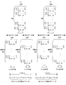
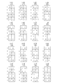
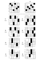
- FIG. 4 is a schematic diagram showing a scanning signal line selection method (3D display, first to fourth fields) of the present liquid crystal display device.
- FIG. 11 is a schematic diagram showing a method for selecting scanning signal lines (3D display, fifth to eighth fields) of the present liquid crystal display device.
- 2D drive 2D drive
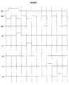
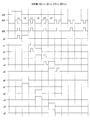
- 3 is a timing chart showing a driving method (3D driving, first to fourth fields) of a gate driver of the present liquid crystal display device.
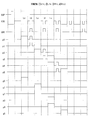
- 6 is a timing chart showing a driving method (3D driving, fifth to eighth fields) of a gate driver of the present liquid crystal display device.
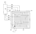
- FIG. 2 is a block diagram showing the configuration of the present liquid crystal display device.
- the present liquid crystal display device includes a liquid crystal panel LCP, a display control circuit DCC, a gate driver GD, a source driver SD, and a backlight BL.
- the liquid crystal panel LCP is provided with a data signal line Sj, a scanning signal line Gj, a storage capacitor wiring (not shown), and a pixel P (i, j).
- a gate driver GD drives the scanning signal line Gi, and a source
- the driver SD drives the data signal line Sj.
- the display control circuit DCC has a GSP (gate start pulse), GCK (gate clock), GOE (gate on enable) signal, output data DATo, SSP according to the type of input data DATi (for 2D video or 3D video).
- GSP gate start pulse
- GCK gate clock
- GOE gate on enable
- output data DATo SSP according to the type of input data DATi (for 2D video or 3D video).
- SCK source clock
- POL source polarity
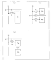
- FIG. 3 shows a configuration example of the pixel P (i, j).
- one pixel electrode PE is provided for one pixel, and the pixel electrode PE is connected to the data signal line Sj and the scanning signal line Gi through the transistor Tr.
- two pixel electrodes PEa and PEb are provided in one pixel, and the pixel electrode PEa is connected to the data signal line Sj and the scanning signal line Gi through the transistor Tra, and the pixel The electrode PEb may be connected to the data signal line Sj and the scanning signal line Gi via the transistor Trb, or two pixel electrodes PEa and PEb are provided in one pixel as shown in FIG.
- PEa is connected to the data signal line Sj and the scanning signal line Gi through the transistor TR, and the pixel electrode PEa and the pixel electrode PEb are connected through a capacitor.
- the liquid crystal panel has 768 rows (including 1366 pixels in one row).
- the first row data group (odd number) from L1.
- the same first and second field data L1x are extracted by extracting 384 rows of row data), and the second row data group (385 rows, which is the sum of the first row and even rows) is created from L1.
- Minute row data is extracted to create the same fifth and sixth field data L1y
- the third row data group (384 rows of odd-numbered row data) is extracted from R1 and the same first data 3 and 4th field data R1x are created
- the 4th row data group (row data for 385 rows which is the sum of the first row and the even row) is extracted from R1 and the same 7th and 8th fields data 1y is created
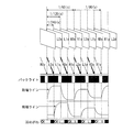
- the first to eighth field data are written in this order (L1x ⁇ L1x ⁇ R1x ⁇ R1x ⁇ L1y ⁇ L1y ⁇ R1y ⁇ R1y) on the liquid crystal panel LCP in a time division manner to display the stereoscopic image (See FIG. 1).
- row data for 385 lines, which is the sum of the first and even lines is extracted from L1 as the second line data group.
- row data for 385 rows which is the sum of the first row and the even row
- R1y is extracted from R1 as the fourth row data group.
- the first three lines of the fifth and sixth fields are the same line data (the second line data of L1), and the first three lines of the seventh and eighth fields are the same.
- the same row data (row data of the second row of R1) can also be used.
- the first, third, fifth, and seventh field data are the first to fourth interpolation field data.
- the frame rate of L1 and R1 is, for example, 60 fps (the input interval of L1 and R1 is 1/60 seconds), and the writing rate of each of the first to eighth field data is 240 fps (the writing time of each field data is 1/240 seconds).
- the backlight is turned on from the second half of the second field data write (second write of L1x) to the first half of the third field data write (first write of R1x), and this includes the backlight ON period.
- the backlight is turned on from the latter half of the fourth field data write (second write of R1x) to the first half of the fifth field data write (first write of L1y), so that the backlight ON period is included.
- the user is made to recognize the display state of R1x.
- the backlight is turned on from the second half of the sixth field data write (second write of L1y) to the first half of the seventh field data write (first write of R1y) so that the backlight ON period is included.
- the backlight is turned on from the second half of the 8th field data write (second write of R1y) to the first half of the next field data write, and the right eye part of the 3D glasses is opened to include this backlight ON period.
- the user is made to recognize the display state of R1y.
- the user recognizes one stereoscopic image by continuously recognizing the display states of L1x, R1x, L1y, and R1y.
- L1x and R1x are written twice, a total of 1536 rows of data are written in 1/60 seconds, and L1y and R1y are written twice, a total of 1540 rows of data in 1/60 seconds.
- the write time for one row data can be secured about 10.8 microseconds.
- the left-eye field data and the right-eye field data are written twice to suppress crosstalk, and image disturbance due to insufficient charging of pixels can be suppressed. Since the writing time of one row data can be secured for about 10.8 microseconds, crosstalk is suppressed even in a liquid crystal panel for double speed driving (lower cost than a liquid crystal panel for quadruple speed driving). High-quality 3D display is possible.
- FIG. 5 shows the relationship between L1 (frame data for left eye), L1x (first and second field data) and L1y (fifth and sixth field data), and R1 (frame data for left eye) and R1x ( It is a schematic diagram which shows the relationship with 3rd and 4th field data) and R1y (7th and 8th field data).
- the row data of the Nth row and the (N + 1) th row of L1x (first and second field data)
- the row data of the Nth row and the (N + 1) th row of R1x are equal to the row data of the Nth row of R1.
- the row data of the first row and the second row of L1x are equal to the row data of the first row of L1
- the row data of the first row and the second row of R1x are the row data of the first row of R1. equal.
- the Mth and M + 1th row data of L1y is the row data of the Mth row of L1.
- the row data of the Mth row and the (M + 1) th row of R1y are equal to the row data of the Mth row of R1.
- the row data of the second row and the third row of L1y are equal to the row data of the second row of L1
- the row data of the second row and the third row of R1y are the row data of the second row of R1y. equal.
- row data of the first row of L1y is equal to the row data of the first row of L1, and the row data of the first row of R1y is the same as the row data of the first row of R1.
- row data of the 768th row of L1y is equal to the row data of the 768th row of L1
- the row data of the 768th row of R1y is equal to the row data of the 768th row of R1.
- L1 frame data for left eye
- L1x first and second field data
- L1y first and sixth field data
- R1 frame data for left eye
- R1x first data
- R1x first data
- R1x first data
- the row data of the N1 and L-1 rows of L1x are equal to the row data of the Nth row of L1
- the row data of the Nth and N-1 rows of R1x are , R1 equal to N row data
- L1y's M row data and M-1 row data are equal to L1's M row data
- R1y's M row data and M-1 row data are equal to R1 Is equal to the row data of M rows.
- the row data is the same for every two rows from the first row to the 768th row, and for each of the fifth to eighth field data, The row data is the same for every two rows from the second row to the 767th row. Therefore, in the writing of the first to fourth field data, as shown in FIG. 6, two lines from the first scanning signal line to the 768th scanning signal line are selected simultaneously to write the fifth to eighth field data. Then, as shown in FIG. 7, two lines are selected simultaneously from the second scanning signal line to the 767th scanning signal line (the first scanning signal line and the 768th scanning signal line are selected one by one).
- the number of selections per 4 field data (1/60 seconds) can be increased to 1538 times, and one selection period (a write time for one row data is secured about 10.8 microseconds).
- one line is selected from the first scanning signal line to the 768th scanning signal line in order.
- the polarity of the write potential is inverted every two pixels from the first pixel to the same column (up to the 768th pixel), and the fifth to eighth field data are written. Is written, the polarity of the write potential is inverted every second pixel from the second pixel in the same column (up to the 767th pixel).
- the polarity of the write potential to the same pixel is inverted with one or two field data and one of two consecutive cycles
- the polarity of the writing potential to the same pixel is reversed, and the polarity of the writing potential is inverted in each cycle data writing period. Adjust.
- the polarity of the write potential to the pixel in the second row and first column is changed from plus (first field data) ⁇ minus (second field data) ⁇ plus (third field data).
- the polarity of the writing potential to the pixel is changed to minus (first field data) ⁇ plus (second field data) ⁇ minus (third field data) ⁇ plus (fourth field data) ⁇ plus (fifth field data) ⁇ minus (Sixth field data) ⁇ plus (seventh field data) ⁇ minus (eighth field data).
- the first, third, fifth, and seventh field data which are interpolation field data, are made equal to the immediately following field data, but are not limited thereto.
- the first, third, fifth, and seventh field data may be overdrive data (LDx, RDx, LDy, RDy) for the immediately following field data.
- LDx is created based on R0y and L1x (according to gradation transition)
- RDx is created based on L1x and R1x (according to gradation transition)
- R1x and L1x RDx is created on the basis of (in response to gradation transition)
- LDy is created on the basis of R1x and L1y (in accordance with gradation transition)
- RDy is created on the basis of L1y and R1y.
- the first, third, fifth, and seventh field data are interpolated field data, but the present invention is not limited to this.
- the second, fourth, sixth, and eighth field data can be used as interpolation field data for black insertion.
- the entire area of the backlight is turned ON / OFF at the same time, but is not limited to this.
- the backlight can be divided into five areas AR1 to AR5 arranged in the scanning direction, and AR1 to AR5 can be sequentially turned on according to the scanning of the scanning signal lines as shown in FIG.
- the polarity of the write potential to the same pixel is inverted by 1 or 2 field data, but the present invention is not limited to this.
- the polarity of the write potential to the same pixel is inverted by 2 or 4 field data, and when writing one first field data in two consecutive cycles, the other first field
- the polarity of the writing potential to the same pixel may be reversed, and the polarity inversion timing of the writing potential may be adjusted in the writing period of each cycle data.
- the polarity of the write potential to the same pixel is inverted with 4 or 8 field data, and one first field data in two consecutive cycles is written and the other first field is written.
- the polarity of the writing potential to the same pixel may be reversed, and the polarity inversion timing of the writing potential may be adjusted in the writing period of each cycle data.
- FIG. 16 is a timing chart showing an operation during 2D display of the gate driver GD shown in FIG.
- the first stage captures “L” of GCK in the first stage
- the first stage captures “L” next to GCK
- the first stage captures “L” of GCK.
- the second stage captures the next “L” of GCK
- the second stage captures the “L” of GCK.
- the third stage captures the next “L” of GCK and is captured at each stage.
- the GCK “L” is configured to be inverted (set to “H”) and output to the corresponding scanning signal line when the GOE is “L”.
- the GCK during 2D display alternates between the “L” period and the “H” period.
- FIG. 17 is a timing chart showing the operation of the gate driver GD during 3D display (the writing period of the first to fourth field data).
- GCK during 3D display has a concave period that changes from “H” to “L” to “H” between the “L” period and the next “L” period.
- the first stage captures “La” of GCK by making GSP active before “La” of GCK
- the first stage captures “Lb” (concave period) of GCK
- the first stage captures “Lb” of GCK.
- the second stage captures “Lc” of GCK.
- the third stage captures “Ld” (concave period) of GCK.
- the fourth stage captures “Le” of GCK.
- the first stage captures “Lb” (concave period) of GCK
- the first stage captures “Lc” of GCK
- the second stage Takes GCK “Ld” (concave period)
- second stage takes GCK “Ld”
- third takes GCK “Le”
- third takes GCK “Le”
- the fourth stage captures “Lf” (concave period) of GCK.
- the signals before masking by the GOE generated in the first to fifth stages are as shown by p0 to p5 in FIG. 17, and the scanning signal g0 of the scanning signal line G0 (one line) becomes “H”.
- the scanning signals g1 and g2 of the scanning signal lines G1 and G2 (2 lines) become “H”
- the scanning signals g3 and g4 of the scanning signal lines G3 and G4 (2 lines) become “H”.
- FIG. 18 is a timing chart showing the operation of the gate driver GD during 3D display (fifth to eighth field data writing periods).
- the first stage captures the GCK “LA” (concave period) by making the GSP active before the GCK “LA” (concave period)
- the first stage captures the GCK “LB”
- the second stage captures the GCK “LC” (concave period)
- the third stage captures the GCK “LC”.
- “LD” is captured and the third stage captures “LD” of GCK
- the fourth stage captures “LE” (concave period) of GCK.
- the first stage captures “LB” of GCK
- the first stage captures “LC” (concave period) of GCK
- the second stage Takes the GLD “LD”
- the second stage captures the GCK “LD”
- the third stage captures the GCK “LE” (concave period)
- the third stage captures the GCK “LE”.
- the fourth stage captures “LF” of GCK.
- the signals before masking by the GOE generated in the first to fifth stages are as shown by p0 to p5 in FIG. 18, and the scanning signals g0 and g1 of the scanning signal lines G0 and G1 (two lines) are obtained.
- the scanning signals g2 and g3 of the scanning signal lines G2 and G3 (two lines) become “H”
- the scanning signals g4 and g5 of the scanning signal lines G4 and G5 two lines) “ H ".
- FIG. 18 can be modified as shown in FIG. That is, the period immediately before “LB” of GCK is set to the “H” period instead of the concave period, and the GSP is activated in synchronization with or before the start of “Lo” immediately before this “H” period. In this way, the first stage can capture “Lo” of GCK, and the first stage can capture “LB” of GCK.
- the first to eighth field data are written on the liquid crystal panel LCP in the order of L1x ⁇ L1x ⁇ R1x ⁇ R1x ⁇ L1y ⁇ L1y ⁇ R1y ⁇ R1y, but the present invention is not limited to this.
- L1x, L1x, R1x, and R1x 4 field data can be written in 1/60 seconds, and R1y, R1y, L1y, and L1y 4 field data can be written in 1/60 seconds.
- a data writing time of about 10.8 microseconds can be secured.
- L1y, L1y, R1x, and R1x 4 field data are written in 1/60 seconds, and R1y, R1y, L1x, and L1x 4 field data are written in 1/60 seconds.
- a data writing time of about 10.8 microseconds can be secured.
- R0y (seventh field data of the previous cycle data), R0y (eighth field data of the previous cycle data), L1x, and L1x four field data are written in 1/60 second
- 4 field data of L1y, L1y, R1x, and R1x are written in 1/60 second
- R1y, R1y, L2x (first field data of the next cycle data)
- L2x first cycle data of the next cycle data
- the display states of L1x ⁇ L1y ⁇ R1y ⁇ R1x can be continuously recognized by writing in the order of L1x ⁇ L1x ⁇ L1y ⁇ L1y ⁇ R1y ⁇ R1y ⁇ R1x ⁇ R1x.
- R0x (seventh field data of previous cycle data), R0x (eighth field data of previous cycle data), L1x, and L1x four field data are written in 1/60 second
- 4 field data of L1y, L1y, R1y, and R1y are written in 1/60 second
- R1x, R1x, L2x (first field data of the next cycle data)
- L2x first cycle data of the next cycle data
- R0y (7th field data of the previous cycle data), R0y (8th field data of the previous cycle data), L1y, and L1y 4 field data are written in 1/60 second
- 4 field data of L1x, L1x, R1x, and R1x are written in 1/60 second
- R1y, R1y, L2y first field data of the next cycle data
- L2y first cycle data of the next cycle data
- R0x (seventh field data of the previous cycle data), R0x (eighth field data of the previous cycle data), L1y, and L1y four field data are written in 1/60 second
- 4 field data of L1x, L1x, R1y, and R1y are written in 1/60 second
- R1x, R1x, L2y first field data of the next cycle data
- L2y first cycle data of the next cycle data
- the first, third, fifth, and seventh field data which are the first to fourth interpolation field data, are the same as the immediately following field data, but this is not limitative. Not. Each of the first, third, fifth, and seventh field data may be overdrive data for the immediately following field data.
- the first interpolation field data, the first pre-eye field data, the second interpolation field data, the second pre-ocular field data, the third interpolated field data, and the first ocular post-field data may be written in this order.
- the first interpolation field data, the first pre-eye field data, the second interpolation field data, the first post-ocular field data, the third interpolation field data, the second pre-ocular field data, the fourth interpolation A configuration may also be adopted in which field data and second-eye post-field data are written in this order.
- the first interpolation field data, the first pre-ocular field data, the second interpolation field data, the second pre-ocular field data, the third interpolated field data, the second post-ocular field data, the fourth interpolator It can also be set as the structure which writes in order of field data and 1st eye post field data.
- the first eye field data, the first interpolation field data, the second eye field data, the second interpolation field data, the first eye field data, the third interpolation field data, the second eye A configuration may also be adopted in which post-use field data and fourth interpolation field data are written in this order.
- the first eye pre-field data, the first interpolation field data, the first eye post-field data, the second interpolation field data, the second eye pre-field data, the third interpolation field data, the second eye A configuration may also be adopted in which post-use field data and fourth interpolation field data are written in this order.
- the first eye pre-field data, the first interpolation field data, the second eye pre-field data, the second interpolation field data, the second eye post-field data, the third interpolation field data, the first eye A configuration may also be adopted in which post-use field data and fourth interpolation field data are written in this order.
- the first eye field data includes the odd-numbered row data of the first eye frame data
- the even-numbered row data of the first eye frame data includes the first eye frame data
- the second-eye pre-field data includes the odd-numbered row data of the second-eye frame data
- the second-eye post-field data includes the even-numbered row data of the second-eye frame data. It can also be configured.
- even-numbered row data of the first eye frame data is included in the first eye field data
- odd-numbered row data of the first eye frame data is included in the first eye field data
- the second-eye pre-field data includes even-numbered row data of the second-eye frame data
- the second-eye post-field data includes odd-numbered row data of the second-eye frame data. It can also be configured.
- the first eye field data includes the odd-numbered row data of the first eye frame data
- the even-numbered row data of the first eye frame data includes the first eye frame data
- the second-eye pre-field data includes even-numbered row data of the second-eye frame data
- the second-eye post-field data includes odd-numbered row data of the second-eye frame data. It can also be configured.
- even-numbered row data of the first eye frame data is included in the first eye field data
- odd-numbered row data of the first eye frame data is included in the first eye field data.
- contains the row data of the odd-numbered rows of the second eye frame data is included in the second eye previous field data
- line data of even lines of the second eye frame data is included in the field data after a second eye It can also be configured.
- each of the first to fourth interpolation field data can be configured to be equal to the immediately following field data.
- each of the first to fourth interpolation field data can be configured to be overdrive data for the immediately following field data.
- the first to fourth interpolation field data may be the same data (for example, black insertion data).
- the row data of the rows other than the start end and the end may be the same as the row data of the preceding stage or the succeeding stage.
- the N-row and N + 1-row row data in the first eye field data is equal to the N-row row data in the first eye frame data.
- the N-row and N + 1-row row data of the field image data for two eyes is equal to the N-row row data of the frame data for the second eye
- the M-row data and the M + 1-row row data for the first eye field data are
- the M-row data of the first eye frame data is equal to the M-row line data
- the M-row and M + 1-row line data of the second-eye post-field data are equal to the M-row line data of the second eye frame data. You can also.
- the M-row and M + 1-row row data of the first eye field data is equal to the M-row row data of the first eye frame data.
- the row data of M rows and M + 1 rows of the field data for two eyes is equal to the row data of M rows of the frame data for the second eye
- the row data of N rows and N + 1 rows of the first eye field data are
- the N-row row data of the second eye field data is equal to the N-row row data of the second eye frame data
- the N-row row data of the second eye-use field data is equal to the N-row row data. You can also.
- the N-row and N + 1-row row data in the first eye field data is equal to the N-row row data in the first eye frame data.
- the M-row and M + 1-row row data of the pre-lens field data is equal to the M-row row data of the second-eye frame data
- the M-row and M + 1-row row data of the first ocular field data is The row data of the first eye frame data is equal to the row data of M rows
- the row data of N rows and N + 1 rows of the second eye post-field data is configured to be equal to the row data of N rows of the second eye frame data. You can also.
- the M-row and M + 1-row row data of the first eye field data is equal to the M-row row data of the first eye frame data.
- the row data of the N-row and N + 1 rows of the pre-lens field data is equal to the row data of the N-row of the second-eye frame data
- the row data of the N-row and N + 1 rows of the first-eye post-field data is
- the N-row line data of the first eye frame data is equal to the row data of the second eye
- the M-row and M + 1-row row data of the second-eye post-field data is equal to the M-row row data of the second eye frame data.
- the row data of N rows and N ⁇ 1 rows of the first eye field data are equal to the row data of N rows of the first eye frame data.
- the row data of the Nth row and the N ⁇ 1th row data of the second eye pre-field data are equal to the row data of the Nth row of the second eye frame data, and the Mth row and the M ⁇ 1th row of the first eye rear field data.
- the row data of the first eye frame data is equal to the M row data of the first eye frame data
- the M eye and M-1 row data of the second eye post-field data are M rows of the second eye frame data.
- a configuration equivalent to row data can also be adopted.
- the row data for the first eye field data M and M-1 rows are equal to the row data for the first eye frame data M rows.
- the M-row data and the M-1 row data of the second-eye front field data are equal to the M-row data of the second-eye frame data, and the first-eye post-field data N rows and N-1 are the same.
- the row data of the row is equal to the row data of N rows of the first eye frame data, and the row data of the second eye field data and the row data of the (N ⁇ 1) rows are N rows of the second eye frame data. It is also possible to adopt a configuration equal to the row data.
- the row data of N rows and N ⁇ 1 rows of the first eye field data are equal to the row data of N rows of the first eye frame data.
- the M-row data and the M-1 row data of the second-eye front field data are equal to the M-row data of the second-eye frame data, and the M-row and M-1 of the first-eye post-field data are the same.
- the row data of the row is equal to the row data of M rows of the first eye frame data
- the row data of N rows and N ⁇ 1 rows of the second eye post-field data are N rows of the second eye frame data. It is also possible to adopt a configuration equal to the row data.
- the row data for the first eye field data M and M-1 rows are equal to the row data for the first eye frame data M rows.
- the N-row data and the N-1-row row data of the second eye pre-field data are equal to the N-row row data of the second-eye frame data, and the N-row and N-1 rows of the first ocular field data are the same.
- the row data of the row is equal to the row data of N rows of the first eye frame data
- the row data of M rows and M ⁇ 1 rows of the second eye post-field data are M rows of the second eye frame data. It is also possible to adopt a configuration equal to the row data.
- the polarity of the write potential is reversed every two pixels from the first pixel or the write potential is changed every two pixels from the second pixel. It can also be set as the structure which reverses polarity.
- the two pixels belonging to the same column among the plurality of pixels corresponding to the row data for the two rows may have the same writing potential polarity.
- the polarity of the write potential to the same pixel can be reversed by 1 or 2 field data.
- n 1 is more desirable from the viewpoint of display quality.
- the display device may be configured to sequentially write the row data for the two rows at the time of stereoscopic display and to sequentially write the row data for one row at the time of flat display.
- the display device may include a gate driver that generates a selection signal for each row of the display unit using a gate clock, and the gate clock waveform may be different between stereoscopic display and planar display.
- the gate clock at the time of flat display is a waveform in which a plurality of pulses are arranged at regular intervals
- the gate clock at the time of stereoscopic display is a waveform in which a part of each of the plurality of pulses is recessed. It can also be.
- the first eye may be a left eye and the second eye may be a right eye.
- the present display device may be configured to include a liquid crystal panel. Moreover, it can also be set as a television receiver (for example, liquid crystal television).
- a television receiver for example, liquid crystal television
- each of the first and second eye frame data includes a plurality of row data
- Each of the second row data groups is a part of the row data included in the first eye frame data
- each of the third and fourth row data groups is a part of the row data included in the second eye frame data.
- Interpolated field data consists of eight field data consisting of data, second-eye post-field data obtained from the fourth row data group, and first to fourth interpolated field data.
- the first eye field data is after the first eye field data and the second eye field data is after the second eye field data in a time-sharing manner. This is a display method for displaying the three-dimensional image by writing in the part.
- the present invention is suitable not only for the liquid crystal display device described above but also for a plasma display, an organic EL display, and the like.
- the present invention is not limited to the above-described embodiments, and those obtained by appropriately modifying the above-described embodiments based on common general technical knowledge and those obtained by combining them are also included in the embodiments of the present invention.
- the display device of the present invention is suitable for a 3D liquid crystal television, for example.
Landscapes
- Engineering & Computer Science (AREA)
- Physics & Mathematics (AREA)
- General Physics & Mathematics (AREA)
- Multimedia (AREA)
- Signal Processing (AREA)
- Chemical & Material Sciences (AREA)
- Crystallography & Structural Chemistry (AREA)
- Nonlinear Science (AREA)
- Computer Hardware Design (AREA)
- Theoretical Computer Science (AREA)
- Optics & Photonics (AREA)
- Control Of Indicators Other Than Cathode Ray Tubes (AREA)
Abstract
第1および第2眼用フレームデータそれぞれが複数の行データからなり、第1および第2の行データ群それぞれを第1眼用フレームデータに含まれる行データの一部とし、第3および第4の行データ群それぞれを第2眼用フレームデータに含まれる行データの一部として、第1の行データ群から得られる第1眼用前フィールドデータ、第2の行データ群から得られる第1眼用後フィールドデータ、第3の行データ群から得られる第2眼用前フィールドデータ、第4の行データ群から得られる第2眼用後フィールドデータ、および第1~第4補間フィールドデータからなる8つのフィールドデータを、補間フィールドデータが連続しないように時分割にて表示部に書き込むことで立体画を表示する。
Description
本発明は、立体表示可能な表示装置に関する。
対となる左眼用の映像および右眼用の映像を時分割で表示し、シャッター眼鏡などによって、左眼用の映像を左眼のみで視認させるとともに右眼用の映像を右眼のみで視認させることで、立体画として認識させる(いわゆる3D表示)技術が注目されている。
特許文献1には、左眼用の映像データを2回書き込んだ後に、右眼用の映像データを2回書き込むことで、クロストーク(左眼に右眼用の映像が視えたり、右眼に左眼用の映像が視えたりする現象)を抑制する技術が開示されている。
しかしながら上記従来の技術では、立体画として認識させる(左右の映像を表示する)のに4回の書き込みが必要となるため、例えば768行(1行に1366個の画素を含む)のパネルを用いた場合に、図28に示すように、768×4=3072個の行データを1/60秒で書き込むことになる。この場合、1個の行データの書き込み時間が5.5マイクロ秒程度しかなく、画素の充電不足による画像乱れが生じ易いという問題があった。
本発明では、画素の充電時間を確保しながらクロストークを抑制しうる3D表示可能な液晶表示装置を提供する。
本表示装置は、1つの立体画に対応する第1眼用フレームデータおよび第2眼用フレームデータに対して、第1および第2眼用フレームデータそれぞれが複数の行データからなり、第1および第2の行データ群それぞれを第1眼用フレームデータに含まれる行データの一部とし、第3および第4の行データ群それぞれを第2眼用フレームデータに含まれる行データの一部として、第1の行データ群から得られる第1眼用前フィールドデータ、第2の行データ群から得られる第1眼用後フィールドデータ、第3の行データ群から得られる第2眼用前フィールドデータ、第4の行データ群から得られる第2眼用後フィールドデータ、および第1~第4補間フィールドデータからなる8つのフィールドデータを、補間フィールドデータが連続することなく、第1眼用後フィールドデータが第1眼用前フィールドデータの後となり、かつ第2眼用後フィールドデータが第2眼用前フィールドデータの後となるように、時分割にて表示部に書き込むことで上記立体画を表示する構成である。
上記構成では、4フィールドデータ(内2つは補間フィールドデータ)単位で立体視が可能となり、これら4フィールドデータを書き込む間に走査される行数(延べの行数)は、第1眼用フレームデータおよび第2眼用フレームデータを2回ずつ書き込む間に走査される行数(延べの行数)よりも少なくなる。これにより、4フィールドデータを書き込むことでクロストークを抑制しつつ、画素の充電不足による画像乱れも抑制することができる。
本発明によれば、画素の充電時間を確保しながらクロストークを抑制しうる3D表示可能な液晶表示装置を実現することができる。
本発明の実施の形態を、図1~27を用いて説明すれば、以下のとおりである。図2は本液晶表示装置の構成を示すブロック図である。同図に示されるように、本液晶表示装置は、液晶パネルLCP、表示制御回路DCC、ゲートドライバGD、ソースドライバSD、およびバックライトBLを備える。液晶パネルLCPには、データ信号線Sj、走査信号線Gj、保持容量配線(図示せず)、および画素P(i,j)が設けられ、ゲートドライバGDは走査信号線Giを駆動し、ソースドライバSDはデータ信号線Sjを駆動する。表示制御回路DCCは、入力データDATiの種類(2D映像用または3D映像用)に応じた、GSP(ゲートスタートパルス)、GCK(ゲートクロック)、GOE(ゲートオンイネーブル)信号、出力データDATo、SSP(ソーススタートパルス)、SCK(ソースクロック)、およびPOL(ソース極性)信号を生成し、GSP、GCK、およびGOE信号をゲートドライバGDに出力し、SSP、SCK、およびPOL信号をソースドライバSDに出力する(後に詳述)。
図3に画素P(i,j)の構成例を示す。本液晶パネルLCPでは、図3(a)のように1つの画素に1つの画素電極PEを設け、画素電極PEを、トランジスタTrを介してデータ信号線Sjおよび走査信号線Giに接続してもよいし、図3(b)のように1つの画素に2つの画素電極PEa・PEbを設け、画素電極PEaを、トランジスタTraを介してデータ信号線Sjおよび走査信号線Giに接続するとともに、画素電極PEbを、トランジスタTrbを介してデータ信号線Sjおよび走査信号線Giに接続してもよいし、図3(c)のように1つの画素に2つの画素電極PEa・PEbを設け、画素電極PEaを、トランジスタTRを介してデータ信号線Sjおよび走査信号線Giに接続するとともに、画素電極PEaおよび画素電極PEbを、容量を介して接続してもよい。
図1および図4は、本液晶表示装置における3D映像用データの表示方法を示している。なお一例として液晶パネルは768行(1行に1366個の画素を含む)とする。本液晶表示装置では、1つの立体画に対応する左眼(第1眼)用フレームデータL1および右眼(第2眼)用フレームデータR1に対して、L1から第1の行データ群(奇数行である384行分の行データ)を抜き出して同一の第1および第2フィールドデータL1xを作成するとともに、L1から第2の行データ群(1番目の行と偶数行の和である385行分の行データ)を抜き出して同一の第5および第6フィールドデータL1yを作成し、さらに、R1から第3の行データ群(奇数行である384行分の行データ)を抜き出して同一の第3および第4フィールドデータR1xを作成するとともに、R1から第4の行データ群(1番目の行と偶数行の和である385行分の行データ)を抜き出して同一の第7および第8フィールドデータR1yを作成し、これら第1~第8フィールドデータを、この順(L1x→L1x→R1x→R1x→L1y→L1y→R1y→R1y)に時分割で液晶パネルLCPに書き込むことで上記立体画を表示する(図1参照)。ここでは第5および第6フィールドデータL1yを作成するのに、L1から第2の行データ群として「1番目の行と偶数行の和である385行分の行データ」を抜き出すとともに、第7および第8フィールドデータR1yを作成するのにR1から第4の行データ群として、1番目の行と偶数行の和である385行分の行データを抜き出す例を示してあるが、これに限定されない。例えば、第5および第6フィールドデータL1yを作成するのに、L1から第2の行データ群として偶数行のみ384行分の行データを抜き出すとともに、第7および第8フィールドデータR1yを作成するのにR1から第4の行データ群として偶数行のみ384行分の行データを抜き出してもよい。この場合は、例えば図27に示すように、第5および第6フィールドの冒頭3行を同一の行データ(L1の第2行の行データ)とし、第7および第8フィールドの冒頭3行を同一の行データ(R1の第2行の行データ)とすることもできる。
なお、第1、第3、第5、第7フィールドデータは第1~第4補間フィールドデータである。また、L1およびR1のフレームレートは、例えば60fps(L1およびR1の入力間隔が1/60秒)であり、第1~第8フィールドデータそれぞれの書き込みレートは、240fps(各フィールドデータの書き込み時間は1/240秒)である。
ここでは、第2フィールドデータの書き込み(L1xの2回目の書き込み)後半から第3フィールドデータの書き込み(R1xの1回目の書き込み)前半にかけてバックライトをONとし、このバックライトのON期間を含むように3D眼鏡の左眼部を開放とすることで、ユーザにL1xの表示状態を認識させる。次いで、第4フィールドデータの書き込み(R1xの2回目の書き込み)後半から第5フィールドデータの書き込み(L1yの1回目の書き込み)前半にかけてバックライトをONとし、このバックライトのON期間を含むように3D眼鏡の右眼部を開放とすることで、ユーザにR1xの表示状態を認識させる。次いで、第6フィールドデータの書き込み(L1yの2回目の書き込み)後半から第7フィールドデータの書き込み(R1yの1回目の書き込み)前半にかけてバックライトをONとし、このバックライトのON期間を含むように3D眼鏡の左眼部を開放とすることで、ユーザにL1yの表示状態を認識させる。次いで、第8フィールドデータの書き込み(R1yの2回目の書き込み)後半から次のフィールドデータの書き込み前半にかけてバックライトをONとし、このバックライトのON期間を含むように3D眼鏡の右眼部を開放とすることで、ユーザにR1yの表示状態を認識させる。このように、L1x、R1x、L1y、およびR1yの表示状態を連続して認識することで、ユーザは1枚の立体画を認識する。
本液晶表示装置では、L1xおよびR1xを2回ずつ、延べ1536個の行データを1/60秒で書き込み、L1yおよびR1yを2回ずつ、延べ1540個の行データを1/60秒で書き込むため、1個の行データの書き込み時間を10.8マイクロ秒程度確保することができる。これにより、左眼用フィールドデータおよび右眼用フィールドデータを2回ずつ書き込んでクロストークを抑制しつつ、画素の充電不足による画像乱れも抑制することができる。そして、1個の行データの書き込み時間を10.8マイクロ秒程度確保することができることから、2倍速駆動用の液晶パネル(4倍速駆動用の液晶パネルよりも低コスト)でもクロストークが抑制された高品位な3D表示が可能となる。
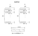
図5は、L1(左眼用フレームデータ)とL1x(第1および第2フィールドデータ)およびL1y(第5および第6フィールドデータ)との関係、並びにR1(左眼用フレームデータ)とR1x(第3および第4フィールドデータ)およびR1y(第7および第8フィールドデータ)との関係を示す模式図である。
図5に示すように、Nを奇数(1,3,・・・767)とするとき、L1x(第1および第2フィールドデータ)の第N行および第N+1行の行データは、L1の第N行の行データに等しく、R1x(第3および第4フィールドデータ)の第N行および第N+1行の行データは、R1の第N行の行データに等しい。例えば、L1xの第1行および第2行の行データは、L1の第1行の行データに等しく、R1xの第1行および第2行の行データは、R1の第1行の行データに等しい。
また、Mを偶数(2,4,・・・766)とするとき、L1y(第5および第6フィールドデータ)の第M行および第M+1行の行データは、L1の第M行の行データに等しく、R1y(第7および第8フィールドデータ)の第M行および第M+1行の行データは、R1の第M行の行データに等しい。例えば、L1yの第2行および第3行の行データは、L1の第2行の行データに等しく、R1yの第2行および第3行の行データは、R1の第2行の行データに等しい。なお、L1yの第1行の行データは、L1の第1行の行データと等しく、R1yの第1行の行データは、R1の第1行の行データと等しくしている。また、L1yの第768行の行データは、L1の第768行の行データと等しく、R1yの第768行の行データは、R1の第768行の行データと等しくしている。
ここでは、L1(左眼用フレームデータ)とL1x(第1および第2フィールドデータ)およびL1y(第5および第6フィールドデータ)との関係、並びにR1(左眼用フレームデータ)とR1x(第3および第4フィールドデータ)およびR1y(第7および第8フィールドデータ)との関係を、図26のように設定することも可能である。すなわち、Nを奇数、Mを偶数とするとき、L1xのN行およびN-1行の行データは、L1のN行の行データに等しく、R1xのN行およびN-1行の行データは、R1のN行の行データに等しく、L1yのM行およびM-1行の行データは、L1のM行の行データに等しく、R1yのM行およびM-1行の行データは、R1のM行の行データに等しくする。
図5に示すように本液晶表示装置では、第1~第4フィールドデータそれぞれについて、第1行から順に第768行まで2行ずつ行データが等しく、第5~第8フィールドデータそれぞれについて、第2行から順に第767行まで2行ずつ行データが等しくなっている。そこで、第1~第4フィールドデータの書き込みでは、図6のように、第1走査信号線から順に第768走査信号線まで2ラインずつ同時選択していき、第5~第8フィールドデータの書き込みでは、図7のように、第2走査信号線から順に第767走査信号線まで2ラインずつ同時選択していく(第1走査信号線と第768走査信号線は1本ずつ選択する)。こうすれば、4フィールドデータあたり(1/60秒)の選択回数を延べ1538回とすることができ、1回の選択期間(1個の行データの書き込み時間を10.8マイクロ秒程度確保することができる。なお、2D映像用データを書き込む場合には、図8のように、第1走査信号線から順に第768走査信号線まで1ラインずつ選択してくことになる。
ここで、第1~第4フィールドデータを書き込むときには、同一列について第1番目の画素から2画素ごとに書き込み電位の極性を反転させ(第768番目の画素まで)、第5~第8フィールドデータを書き込むときには、同一列について第2番目の画素から2画素ごとに書き込み電位の極性を反転させる(第767番目の画素まで)。加えて、第1~第8フィールドデータを1サイクルデータとして、1つのサイクルデータを書き込むときには、同一画素への書き込み電位の極性を、1または2フィールドデータで反転させるとともに、連続する2サイクルの一方の第1フィールドデータを書き込むときと、他方の第1フィールドデータを書き込むときとで、同一画素への書き込み電位の極性を逆にし、かつ各サイクルデータの書き込み期間において、書き込み電位の極性の反転タイミングを合わせる。
具体的には、図9に示すように、例えば2行1列目の画素への書き込み電位の極性を、プラス(第1フィールドデータ)→マイナス(第2フィールドデータ)→プラス(第3フィールドデータ)→マイナス(第4フィールドデータ)→プラス(第5フィールドデータ)→マイナス(第6フィールドデータ)→プラス(第7フィールドデータ)→マイナス(第8フィールドデータ)とし、例えば3行1列目の画素への書き込み電位の極性を、マイナス(第1フィールドデータ)→プラス(第2フィールドデータ)→マイナス(第3フィールドデータ)→プラス(第4フィールドデータ)→プラス(第5フィールドデータ)→マイナス(第6フィールドデータ)→プラス(第7フィールドデータ)→マイナス(第8フィールドデータ)とする。
図1・4では、補間フィールドデータである第1、第3、第5、第7フィールドデータを、直後のフィールドデータと等しくしているがこれに限定されない。図10に示すように、第1、第3、第5、第7フィールドデータを、直後のフィールドデータに対するオーバードライブ用のデータ(LDx、RDx、LDy、RDy)とすることもできる。具体的には、R0yとL1xとに基づいて(階調遷移に応じて)LDxを作成し、L1xとR1xとに基づいて(階調遷移に応じて)RDxを作成し、R1xとL1xとに基づいて(階調遷移に応じて)RDxを作成し、R1xとL1yとに基づいて(階調遷移に応じて)LDyを作成し、L1yとR1yとに基づいてRDyを作成する。こうすれば、動きの激しい動画をより鮮明に表示することができる。
図1・4では、第1、第3、第5、第7フィールドデータを補間フィールドデータとしているがこれに限定されない。例えば図11に示すように、第2、第4、第6、第8フィールドデータを黒挿入用の補間フィールドデータとすることもできる。
図4では、バックライトの全領域を同時にON・OFFしているがこれに限定されない。例えば図12に示すように、バックライトを走査方向に並ぶ5つの領域AR1~AR5に分け、図13に示すように、走査信号線の走査に従ってAR1~AR5を順次ONさせることもできる。
また、図9では、同一画素への書き込み電位の極性を、1または2フィールドデータで反転させているがこれに限定されない。例えば、図14に示すように、同一画素への書き込み電位の極性を、2または4フィールドデータで反転させるとともに、連続する2サイクルの一方の第1フィールドデータを書き込むときと、他方の第1フィールドデータを書き込むときとで、同一画素への書き込み電位の極性を逆にし、かつ各サイクルデータの書き込み期間において、書き込み電位の極性の反転タイミングを合わせてもよい。また、図15に示すように、同一画素への書き込み電位の極性を、4または8フィールドデータで反転させるとともに、連続する2サイクルの一方の第1フィールドデータを書き込むときと、他方の第1フィールドデータを書き込むときとで、同一画素への書き込み電位の極性を逆にし、かつ各サイクルデータの書き込み期間において、書き込み電位の極性の反転タイミングを合わせてもよい。
図16は、図2に示すゲートドライバGDの2D表示時の動作を示すタイミングチャートである。図16に示されるように、本ゲートドライバは、初段がGCKの「L」を取り込むと、第1段は、GCKの次の「L」を取り込み、第1段がGCKの「L」を取り込むと、第2段は、GCKの次の「L」を取り込み、第2段がGCKの「L」を取り込むと、第3段は、GCKの次の「L」を取り込み、各段で取り込まれたGCK「L」は、GOEが「L」のときに、対応する走査信号線に反転して(「H」にして)出力されるように構成されている。そして、2D表示時のGCKは、「L」の期間と「H」の期間とが交互に入れ替わるようになっている。
図17は、ゲートドライバGDの3D表示時(第1~第4フィールドデータの書き込み期間)の動作を示すタイミングチャートである。図17に示されるように、3D表示時のGCKは、「L」の期間と次の「L」の期間との間に、「H」→「L」→「H」と変化する凹期間を有している。したがって、GSPをGCKの「La」の前にアクティブとしておくことで初段がGCKの「La」を取り込むと、第1段は、GCKの「Lb」(凹期間)を取り込み、第1段がGCKの「Lb」を取り込むと、第2段は、GCKの「Lc」を取り込み、第2段がGCKの「Lc」を取り込むと、第3段は、GCKの「Ld」(凹期間)を取り込み、第3段がGCKの「Ld」を取り込むと、第4段は、GCKの「Le」を取り込む。これと並行して、初段がGCKの「Lb」(凹期間)を取り込むと、第1段は、GCKの「Lc」を取り込み、第1段がGCKの「Lc」を取り込むと、第2段は、GCKの「Ld」(凹期間)を取り込み、第2段がGCKの「Ld」を取り込むと、第3段は、GCKの「Le」を取り込み、第3段がGCKの「Le」を取り込むと、第4段は、GCKの「Lf」(凹期間)を取り込む。
これにより、第1~第5段で生成された、GOEによるマスク前の信号は、図17のp0~p5のようになり、走査信号線G0(1本)の走査信号g0が「H」となった後に、走査信号線G1・G2(2本)の走査信号g1・g2が「H」となり、ついで、走査信号線G3・G4(2本)の走査信号g3・g4が「H」となる。
図18は、ゲートドライバGDの3D表示時(第5~第8フィールドデータの書き込み期間)の動作を示すタイミングチャートである。ここでは、GSPをGCKの「LA」(凹期間)の前にアクティブとしておくことで初段がGCKの「LA」(凹期間)を取り込むと、第1段は、GCKの「LB」を取り込み、第1段がGCKの「LB」を取り込むと、第2段は、GCKの「LC」(凹期間)を取り込み、第2段がGCKの「LC」を取り込むと、第3段は、GCKの「LD」を取り込み、第3段がGCKの「LD」を取り込むと、第4段は、GCKの「LE」(凹期間)を取り込む。これと並行して、初段がGCKの「LB」を取り込むと、第1段は、GCKの「LC」(凹期間)を取り込み、第1段がGCKの「LC」を取り込むと、第2段は、GCKの「LD」を取り込み、第2段がGCKの「LD」を取り込むと、第3段は、GCKの「LE」(凹期間)を取り込み、第3段がGCKの「LE」を取り込むと、第4段は、GCKの「LF」を取り込む。
これにより、第1~第5段で生成された、GOEによるマスク前の信号は、図18のp0~p5のようになり、走査信号線G0・G1(2本)の走査信号g0・g1が「H」となった後に、走査信号線G2・G3(2本)の走査信号g2・g3が「H」となり、ついで、走査信号線G4・G5(2本)の走査信号g4・g5が「H」となる。
なお、図18を変形して図19のようにすることもできる。すなわち、GCKの「LB」の直前を凹期間ではなく「H」期間とし、この「H」期間の直前の「Lo」の開始と同期して、あるいは開始前にGSPをアクティブとする。こうすれば、初段がGCKの「Lo」を取り込み、第1段は、GCKの「LB」を取り込むことができる。
図1・4では、第1~第8フィールドデータを、L1x→L1x→R1x→R1x→L1y→L1y→R1y→R1yの順に液晶パネルLCPに書き込んでいるがこれに限定されない。
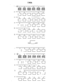
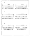
例えば、図20(a)のように、L1x→L1x→R1y→R1y→L1y→L1y→R1x→R1xの順に書き込み、L1x→R1y→L1y→R1xの表示状態を連続して認識させることもできる。この場合も、L1x、L1x、R1y、およびR1yの4フィールドデータを1/60秒で書き込み、L1y、L1y、R1x、およびR1xの4フィールドデータを1/60秒で書き込めばよく、1個の行データの書き込み時間を10.8マイクロ秒程度確保することができる。
また、図20(b)のように、L1y→L1y→R1x→R1x→L1x→L1x→R1y→R1yの順に書き込み、L1y→R1x→L1x→R1yの表示状態を連続して認識させることもできる。この場合も、L1y、L1y、R1x、およびR1xの4フィールドデータを1/60秒で書き込み、L1x、L1x、R1y、およびR1yの4フィールドデータを1/60秒で書き込めばよく、1個の行データの書き込み時間を10.8マイクロ秒程度確保することができる。
また、図20(c)のように、L1y→L1y→R1y→R1y→L1x→L1x→R1x→R1xの順に書き込み、L1y→R1y→L1x→R1xの表示状態を連続して認識させることもできる。この場合も、L1y、L1y、R1y、およびR1yの4フィールドデータを1/60秒で書き込み、L1x、L1x、R1x、およびR1xの4フィールドデータを1/60秒で書き込めばよく、1個の行データの書き込み時間を10.8マイクロ秒程度確保することができる。
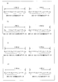
また、図21(a)のように、R1x→R1x→L1x→L1x→R1y→R1y→L1y→L1yの順に書き込み、R1x→L1x→R1y→L1yの表示状態を連続して認識させることもできる。この場合も、R1x、R1x、L1x、およびL1xの4フィールドデータを1/60秒で書き込み、R1y、R1y、L1y、およびL1yの4フィールドデータを1/60秒で書き込めばよく、1個の行データの書き込み時間を10.8マイクロ秒程度確保することができる。
例えば、図21(b)のように、R1x→R1x→L1y→L1y→R1y→R1y→L1x→L1xの順に書き込み、R1x→L1y→R1y→L1xの表示状態を連続して認識させることもできる。この場合も、R1x、R1x、L1y、およびL1yの4フィールドデータを1/60秒で書き込み、R1y、R1y、L1x、およびL1xの4フィールドデータを1/60秒で書き込めばよく、1個の行データの書き込み時間を10.8マイクロ秒程度確保することができる。
また、図21(c)のように、R1y→R1y→L1x→L1x→R1x→R1x→L1y→L1yの順に書き込み、R1y→L1x→R1x→L1yの表示状態を連続して認識させることもできる。この場合も、R1y、R1y、L1x、およびL1xの4フィールドデータを1/60秒で書き込み、R1x、R1x、L1y、およびL1yの4フィールドデータを1/60秒で書き込めばよく、1個の行データの書き込み時間を10.8マイクロ秒程度確保することができる。
また、図21(d)のように、R1y→R1y→L1y→L1y→R1x→R1x→L1x→L1xの順に書き込み、R1y→L1y→R1x→L1xの表示状態を連続して認識させることもできる。この場合も、R1y、R1y、L1y、およびL1yの4フィールドデータを1/60秒で書き込み、R1x、R1x、L1x、およびL1xの4フィールドデータを1/60秒で書き込めばよく、1個の行データの書き込み時間を10.8マイクロ秒程度確保することができる。
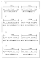
また、図22(a)のように、L1x→L1x→R1x→R1x→R1y→R1y→L1y→L1yの順に書き込み、L1x→R1x→R1y→L1yの表示状態を連続して認識させることもできる。この場合も、L1x、L1x、R1x、およびR1xの4フィールドデータを1/60秒で書き込み、R1y、R1y、L1y、およびL1yの4フィールドデータを1/60秒で書き込めばよく、1個の行データの書き込み時間を10.8マイクロ秒程度確保することができる。
また、図22(b)のように、L1x→L1x→R1y→R1y→R1x→R1x→L1y→L1yの順に書き込み、L1x→R1y→R1x→L1yの表示状態を連続して認識させることもできる。この場合も、L1x、L1x、R1y、およびR1yの4フィールドデータを1/60秒で書き込み、R1x、R1x、L1y、およびL1yの4フィールドデータを1/60秒で書き込めばよく、1個の行データの書き込み時間を10.8マイクロ秒程度確保することができる。
また、図22(c)のように、L1y→L1y→R1x→R1x→R1y→R1y→L1x→L1xの順に書き込み、L1y→R1x→R1y→L1xの表示状態を連続して認識させることもできる。この場合も、L1y、L1y、R1x、およびR1xの4フィールドデータを1/60秒で書き込み、R1y、R1y、L1x、およびL1xの4フィールドデータを1/60秒で書き込めばよく、1個の行データの書き込み時間を10.8マイクロ秒程度確保することができる。
また、図22(d)のように、L1y→L1y→R1y→R1y→R1x→R1x→L1x→L1xの順に書き込み、L1y→R1y→R1x→L1xの表示状態を連続して認識させることもできる。この場合も、L1y、L1y、R1y、およびR1yの4フィールドデータを1/60秒で書き込み、R1x、R1x、L1x、およびL1xの4フィールドデータを1/60秒で書き込めばよく、1個の行データの書き込み時間を10.8マイクロ秒程度確保することができる。
また、図23(a)のように、R1x→R1x→L1x→L1x→L1y→L1y→R1y→R1yの順に書き込み、R1x→L1x→L1y→R1yの表示状態を連続して認識させることもできる。この場合も、R1x、R1x、L1x、およびL1xの4フィールドデータを1/60秒で書き込み、L1y、L1y、R1y、およびR1yの4フィールドデータを1/60秒で書き込めばよく、1個の行データの書き込み時間を10.8マイクロ秒程度確保することができる。
また、図23(b)のように、R1x→R1x→L1y→L1y→L1x→L1x→R1y→R1yの順に書き込み、R1x→L1y→L1x→R1yの表示状態を連続して認識させることもできる。この場合も、R1x、R1x、L1y、およびL1yの4フィールドデータを1/60秒で書き込み、L1x、L1x、R1y、およびR1yの4フィールドデータを1/60秒で書き込めばよく、1個の行データの書き込み時間を10.8マイクロ秒程度確保することができる。
また、図23(c)のように、R1y→R1y→L1x→L1x→L1y→L1y→R1x→R1xの順に書き込み、R1y→L1x→L1y→R1xの表示状態を連続して認識させることもできる。この場合も、R1y、R1y、L1x、およびL1xの4フィールドデータを1/60秒で書き込み、L1y、L1y、R1x、およびR1xの4フィールドデータを1/60秒で書き込めばよく、1個の行データの書き込み時間を10.8マイクロ秒程度確保することができる。
また、図23(d)のように、R1y→R1y→L1y→L1y→L1x→L1x→R1x→R1xの順に書き込み、R1y→L1y→L1x→R1xの表示状態を連続して認識させることもできる。この場合も、R1y、R1y、L1y、およびL1yの4フィールドデータを1/60秒で書き込み、L1x、L1x、R1x、およびR1xの4フィールドデータを1/60秒で書き込めばよく、1個の行データの書き込み時間を10.8マイクロ秒程度確保することができる。
また、図24(a)のように、L1x→L1x→L1y→L1y→R1x→R1x→R1y→R1yの順に書き込み、L1x→L1y→R1x→R1yの表示状態を連続して認識させることもできる。この場合は、R0y(1つ前のサイクルデータの第7フィールドデータ)、R0y(1つ前のサイクルデータの第8フィールドデータ)、L1x、およびL1xの4フィールドデータを1/60秒で書き込み、L1y、L1y、R1x、およびR1xの4フィールドデータを1/60秒で書き込み、R1y、R1y、L2x(1つ後のサイクルデータの第1フィールドデータ)、およびL2x(1つ後のサイクルデータの第2フィールドデータ)の4フィールドデータを1/60秒で書き込めばよく、1個の行データの書き込み時間を10.8マイクロ秒程度確保することができる。
また、図24(b)のように、L1x→L1x→L1y→L1y→R1y→R1y→R1x→R1xの順に書き込み、L1x→L1y→R1y→R1xの表示状態を連続して認識させることもできる。この場合は、R0x(1つ前のサイクルデータの第7フィールドデータ)、R0x(1つ前のサイクルデータの第8フィールドデータ)、L1x、およびL1xの4フィールドデータを1/60秒で書き込み、L1y、L1y、R1y、およびR1yの4フィールドデータを1/60秒で書き込み、R1x、R1x、L2x(1つ後のサイクルデータの第1フィールドデータ)、およびL2x(1つ後のサイクルデータの第2フィールドデータ)の4フィールドデータを1/60秒で書き込めばよく、1個の行データの書き込み時間を10.8マイクロ秒程度確保することができる。
また、図24(c)のように、L1y→L1y→L1x→L1x→R1x→R1x→R1y→R1yの順に書き込み、L1y→L1x→R1x→R1yの表示状態を連続して認識させることもできる。この場合は、R0y(1つ前のサイクルデータの第7フィールドデータ)、R0y(1つ前のサイクルデータの第8フィールドデータ)、L1y、およびL1yの4フィールドデータを1/60秒で書き込み、L1x、L1x、R1x、およびR1xの4フィールドデータを1/60秒で書き込み、R1y、R1y、L2y(1つ後のサイクルデータの第1フィールドデータ)、およびL2y(1つ後のサイクルデータの第2フィールドデータ)の4フィールドデータを1/60秒で書き込めばよく、1個の行データの書き込み時間を10.8マイクロ秒程度確保することができる。
また、図24(d)のように、L1y→L1y→L1x→L1x→R1y→R1y→R1x→R1xの順に書き込み、L1y→L1x→R1y→R1xの表示状態を連続して認識させることもできる。この場合は、R0x(1つ前のサイクルデータの第7フィールドデータ)、R0x(1つ前のサイクルデータの第8フィールドデータ)、L1y、およびL1yの4フィールドデータを1/60秒で書き込み、L1x、L1x、R1y、およびR1yの4フィールドデータを1/60秒で書き込み、R1x、R1x、L2y(1つ後のサイクルデータの第1フィールドデータ)、およびL2y(1つ後のサイクルデータの第2フィールドデータ)の4フィールドデータを1/60秒で書き込めばよく、1個の行データの書き込み時間を10.8マイクロ秒程度確保することができる。
また、図25(a)のように、R1x→R1x→R1y→R1y→L1x→L1x→L1y→L1yの順に書き込み、R1x→R1y→L1x→L1yの表示状態を連続して認識させることもできる。この場合は、L0y(1つ前のサイクルデータの第7フィールドデータ)、L0y(1つ前のサイクルデータの第8フィールドデータ)、R1x、およびR1xの4フィールドデータを1/60秒で書き込み、R1y、R1y、L1x、およびL1xの4フィールドデータを1/60秒で書き込み、L1y、L1y、R2x(1つ後のサイクルデータの第1フィールドデータ)、およびR2x(1つ後のサイクルデータの第2フィールドデータ)の4フィールドデータを1/60秒で書き込めばよく、1個の行データの書き込み時間を10.8マイクロ秒程度確保することができる。
また、図25(b)のように、R1x→R1x→R1y→R1y→L1y→L1y→L1x→L1xの順に書き込み、R1x→R1y→L1y→L1xの表示状態を連続して認識させることもできる。この場合は、L0x(1つ前のサイクルデータの第7フィールドデータ)、L0x(1つ前のサイクルデータの第8フィールドデータ)、R1x、およびR1xの4フィールドデータを1/60秒で書き込み、R1y、R1y、L1y、およびL1yの4フィールドデータを1/60秒で書き込み、L1x、L1x、R2x(1つ後のサイクルデータの第1フィールドデータ)、およびR2x(1つ後のサイクルデータの第2フィールドデータ)の4フィールドデータを1/60秒で書き込めばよく、1個の行データの書き込み時間を10.8マイクロ秒程度確保することができる。
また、図25(c)のように、R1y→R1y→R1x→R1x→L1x→L1x→L1y→L1yの順に書き込み、R1y→R1x→L1x→L1yの表示状態を連続して認識させることもできる。この場合は、L0y(1つ前のサイクルデータの第7フィールドデータ)、L0y(1つ前のサイクルデータの第8フィールドデータ)、R1y、およびR1yの4フィールドデータを1/60秒で書き込み、R1x、R1x、L1x、およびL1xの4フィールドデータを1/60秒で書き込み、L1y、L1y、R2y(1つ後のサイクルデータの第1フィールドデータ)、およびR2y(1つ後のサイクルデータの第2フィールドデータ)の4フィールドデータを1/60秒で書き込めばよく、1個の行データの書き込み時間を10.8マイクロ秒程度確保することができる。
また、図25(d)のように、R1y→R1y→R1x→R1x→L1y→L1y→L1x→L1xの順に書き込み、R1y→R1x→L1y→L1xの表示状態を連続して認識させることもできる。この場合は、L0x(1つ前のサイクルデータの第7フィールドデータ)、L0x(1つ前のサイクルデータの第8フィールドデータ)、R1y、およびR1yの4フィールドデータを1/60秒で書き込み、R1x、R1x、L1y、およびL1yの4フィールドデータを1/60秒で書き込み、L1x、L1x、R2y(1つ後のサイクルデータの第1フィールドデータ)、およびR2y(1つ後のサイクルデータの第2フィールドデータ)の4フィールドデータを1/60秒で書き込めばよく、1個の行データの書き込み時間を10.8マイクロ秒程度確保することができる。
図20~図25の構成では、第1~第4補間フィールドデータである第1、第3、第5、および第7フィールドデータそれぞれを、直後のフィールドデータと同一にしているが、これに限定されない。第1、第3、第5、および第7フィールドデータそれぞれを、直後のフィールドデータに対するオーバードライブ用のデータとすることもできる。
このように、本表示装置では、第1補間フィールドデータ、第1眼用前フィールドデータ、第2補間フィールドデータ、第2眼用前フィールドデータ、第3補間フィールドデータ、第1眼用後フィールドデータ、第4補間フィールドデータ、第2眼用後フィールドデータの順に書き込む構成とすることもできる。
本表示装置では、第1補間フィールドデータ、第1眼用前フィールドデータ、第2補間フィールドデータ、第1眼用後フィールドデータ、第3補間フィールドデータ、第2眼用前フィールドデータ、第4補間フィールドデータ、第2眼用後フィールドデータの順に書き込む構成とすることもできる。
本表示装置では、第1補間フィールドデータ、第1眼用前フィールドデータ、第2補間フィールドデータ、第2眼用前フィールドデータ、第3補間フィールドデータ、第2眼用後フィールドデータ、第4補間フィールドデータ、第1眼用後フィールドデータの順に書き込む構成とすることもできる。
本表示装置では、第1眼用前フィールドデータ、第1補間フィールドデータ、第2眼用前フィールドデータ、第2補間フィールドデータ、第1眼用後フィールドデータ、第3補間フィールドデータ、第2眼用後フィールドデータ、第4補間フィールドデータの順に書き込む構成とすることもできる。
本表示装置では、第1眼用前フィールドデータ、第1補間フィールドデータ、第1眼用後フィールドデータ、第2補間フィールドデータ、第2眼用前フィールドデータ、第3補間フィールドデータ、第2眼用後フィールドデータ、第4補間フィールドデータの順に書き込む構成とすることもできる。
本表示装置では、第1眼用前フィールドデータ、第1補間フィールドデータ、第2眼用前フィールドデータ、第2補間フィールドデータ、第2眼用後フィールドデータ、第3補間フィールドデータ、第1眼用後フィールドデータ、第4補間フィールドデータの順に書き込む構成とすることもできる。
本表示装置では、第1眼用前フィールドデータに第1眼用フレームデータの奇数行の行データが含まれ、第1眼用後フィールドデータに第1眼用フレームデータの偶数行の行データが含まれ、第2眼用前フィールドデータに第2眼用フレームデータの奇数行の行データが含まれ、第2眼用後フィールドデータに第2眼用フレームデータの偶数行の行データが含まれる構成とすることもできる。
本表示装置では、第1眼用前フィールドデータに第1眼用フレームデータの偶数行の行データが含まれ、第1眼用後フィールドデータに第1眼用フレームデータの奇数行の行データが含まれ、第2眼用前フィールドデータに第2眼用フレームデータの偶数行の行データが含まれ、第2眼用後フィールドデータに第2眼用フレームデータの奇数行の行データが含まれる構成とすることもできる。
本表示装置では、第1眼用前フィールドデータに第1眼用フレームデータの奇数行の行データが含まれ、第1眼用後フィールドデータに第1眼用フレームデータの偶数行の行データが含まれ、第2眼用前フィールドデータに第2眼用フレームデータの偶数行の行データが含まれ、第2眼用後フィールドデータに第2眼用フレームデータの奇数行の行データが含まれる構成とすることもできる。
本表示装置では、第1眼用前フィールドデータに第1眼用フレームデータの偶数行の行データが含まれ、第1眼用後フィールドデータに第1眼用フレームデータの奇数行の行データが含まれ、第2眼用前フィールドデータに第2眼用フレームデータの奇数行の行データが含まれ、第2眼用後フィールドデータに第2眼用フレームデータの偶数行の行データが含まれる構成とすることもできる。
本表示装置では、第1~第4補間フィールドデータそれぞれが直後のフィールドデータに等しい構成とすることもできる。
本表示装置では、第1~第4補間フィールドデータそれぞれが直後のフィールドデータに等しい構成とすることもできる。
本表示装置では、第1~第4補間フィールドデータそれぞれが直後のフィールドデータに対するオーバードライブ用のデータである構成とすることもできる。
本表示装置では、第1~第4補間フィールドデータが同一のデータ(例えば、黒挿入用のデータ)である構成とすることもできる。
本表示装置では、上記8つのフィールドデータそれぞれにおいては、始端および末端以外の行の行データとその前段あるいは後段の行データとが同一となっている構成とすることもできる。
本表示装置では、同一である2行分の行データを同時に書き込んでいく構成とすることもできる。
本表示装置では、Nを奇数、Mを偶数とするとき、第1眼用前フィールドデータのN行およびN+1行の行データは、第1眼用フレームデータのN行の行データに等しく、第2眼用前フィールドデータのN行およびN+1行の行データは、第2眼用フレームデータのN行の行データに等しく、第1眼用後フィールドデータのM行およびM+1行の行データは、第1眼用フレームデータのM行の行データに等しく、第2眼用後フィールドデータのM行およびM+1行の行データは、第2眼用フレームデータのM行の行データに等しい構成とすることもできる。
本表示装置では、Nを奇数、Mを偶数とするとき、第1眼用前フィールドデータのM行およびM+1行の行データは、第1眼用フレームデータのM行の行データに等しく、第2眼用前フィールドデータのM行およびM+1行の行データは、第2眼用フレームデータのM行の行データに等しく、第1眼用後フィールドデータのN行およびN+1行の行データは、第1眼用フレームデータのN行の行データに等しく、第2眼用後フィールドデータのN行およびN+1行の行データは、第2眼用フレームデータのN行の行データに等しい構成とすることもできる。
本表示装置では、Nを奇数、Mを偶数とするとき、第1眼用前フィールドデータのN行およびN+1行の行データは、第1眼用フレームデータのN行の行データに等しく、第2眼用前フィールドデータのM行およびM+1行の行データは、第2眼用フレームデータのM行の行データに等しく、第1眼用後フィールドデータのM行およびM+1行の行データは、第1眼用フレームデータのM行の行データに等しく、第2眼用後フィールドデータのN行およびN+1行の行データは、第2眼用フレームデータのN行の行データに等しい構成とすることもできる。
本表示装置では、Nを奇数、Mを偶数とするとき、第1眼用前フィールドデータのM行およびM+1行の行データは、第1眼用フレームデータのM行の行データに等しく、第2眼用前フィールドデータのN行およびN+1行の行データは、第2眼用フレームデータのN行の行データに等しく、第1眼用後フィールドデータのN行およびN+1行の行データは、第1眼用フレームデータのN行の行データに等しく、第2眼用後フィールドデータのM行およびM+1行の行データは、第2眼用フレームデータのM行の行データに等しい構成とすることもできる。
本表示装置では、Nを奇数、Mを偶数とするとき、第1眼用前フィールドデータのN行およびN-1行の行データは、第1眼用フレームデータのN行の行データに等しく、
第2眼用前フィールドデータのN行およびN-1行の行データは、第2眼用フレームデータのN行の行データに等しく、第1眼用後フィールドデータのM行およびM-1行の行データは、第1眼用フレームデータのM行の行データに等しく、第2眼用後フィールドデータのM行およびM-1行の行データは、第2眼用フレームデータのM行の行データに等しい構成とすることもできる。
第2眼用前フィールドデータのN行およびN-1行の行データは、第2眼用フレームデータのN行の行データに等しく、第1眼用後フィールドデータのM行およびM-1行の行データは、第1眼用フレームデータのM行の行データに等しく、第2眼用後フィールドデータのM行およびM-1行の行データは、第2眼用フレームデータのM行の行データに等しい構成とすることもできる。
本表示装置では、Nを奇数、Mを偶数とするとき、第1眼用前フィールドデータのM行およびM-1行の行データは、第1眼用フレームデータのM行の行データに等しく、第2眼用前フィールドデータのM行およびM-1行の行データは、第2眼用フレームデータのM行の行データに等しく、第1眼用後フィールドデータのN行およびN-1行の行データは、第1眼用フレームデータのN行の行データに等しく、第2眼用後フィールドデータのN行およびN-1行の行データは、第2眼用フレームデータのN行の行データに等しい構成とすることもできる。
本表示装置では、Nを奇数、Mを偶数とするとき、第1眼用前フィールドデータのN行およびN-1行の行データは、第1眼用フレームデータのN行の行データに等しく、第2眼用前フィールドデータのM行およびM-1行の行データは、第2眼用フレームデータのM行の行データに等しく、第1眼用後フィールドデータのM行およびM-1行の行データは、第1眼用フレームデータのM行の行データに等しく、第2眼用後フィールドデータのN行およびN-1行の行データは、第2眼用フレームデータのN行の行データに等しい構成とすることもできる。
本表示装置では、Nを奇数、Mを偶数とするとき、第1眼用前フィールドデータのM行およびM-1行の行データは、第1眼用フレームデータのM行の行データに等しく、第2眼用前フィールドデータのN行およびN-1行の行データは、第2眼用フレームデータのN行の行データに等しく、第1眼用後フィールドデータのN行およびN-1行の行データは、第1眼用フレームデータのN行の行データに等しく、第2眼用後フィールドデータのM行およびM-1行の行データは、第2眼用フレームデータのM行の行データに等しい構成とすることもできる。
本表示装置では、8つのフィールドデータそれぞれを書き込むときには、同一列について、1番目の画素から2画素ごとに書き込み電位の極性を反転させるか、あるいは、2番目の画素から2画素ごとに書き込み電位の極性を反転させる構成とすることもできる。
本表示装置では、上記2行分の行データに対応する複数の画素のうち同一列に属する2つの画素については、書き込み電位の極性を同一とする構成とすることもできる。
本表示装置では、上記8つのフィールドデータを書き込むときには、同一画素への書き込み電位の極性を1または2フィールドデータで反転させる構成とすることもできる。
本表示装置では、上記8つのフィールドデータを1サイクルデータとして、n個(nは自然数)のサイクルデータを1組とするとき、液晶パネルを用いた場合は、連続する2組の一方で最初のフィールドデータを書き込むときと、他方で最初のフィールドデータを書き込むときとで、同一画素への書き込み電位の極性を逆にする構成とすることが信頼性の観点から望ましい。なお、n=1とすることが表示品位の観点からより望ましい。
本表示装置では、立体表示時には、上記2行分の行データを順次書き込んでいき、平面表示時には1行分の行データを順次書き込んでいく構成とすることもできる。
本表示装置では、ゲートクロックを用いて表示部の各行の選択信号を生成するゲートドライバを備え、立体表示時と平面表示時とで、上記ゲートクロックの波形が異なる構成とすることもできる。
本表示装置では、平面表示時のゲートクロックは、一定間隔をおいて複数のパルスが並ぶ波形であり、立体表示時のゲートクロックは、上記複数のパルスそれぞれの一部分を凹ませた波形である構成とすることもできる。
本表示装置では、上記第1眼は左眼で、第2眼は右眼である構成とすることもできる。
本表示装置では、液晶パネルを備える構成とすることもできる。また、テレビジョン受像機(例えば、液晶テレビ)とすることもできる。
本表示方法は、1つの立体画に対応する第1眼用フレームデータおよび第2眼用フレームデータに対して、第1および第2眼用フレームデータそれぞれが複数の行データからなり、第1および第2の行データ群それぞれを第1眼用フレームデータに含まれる行データの一部とし、第3および第4の行データ群それぞれを第2眼用フレームデータに含まれる行データの一部として、第1の行データ群から得られる第1眼用前フィールドデータ、第2の行データ群から得られる第1眼用後フィールドデータ、第3の行データ群から得られる第2眼用前フィールドデータ、第4の行データ群から得られる第2眼用後フィールドデータ、および第1~第4補間フィールドデータからなる8つのフィールドデータを、補間フィールドデータが連続することなく、第1眼用後フィールドデータが第1眼用前フィールドデータの後となり、かつ第2眼用後フィールドデータが第2眼用前フィールドデータの後となるように、時分割にて表示部に書き込むことで上記立体画を表示する表示方法である。
本発明は、上記の液晶表示装置だけでなく、プラズマディスプレイや有機ELディスプレイ等にも好適である。
本発明は上記の実施の形態に限定されるものではなく、上記実施の形態を技術常識に基づいて適宜変更したものやそれらを組み合わせて得られるものも本発明の実施の形態に含まれる。
本発明の表示装置は、例えば、3D液晶テレビに好適である。
L1 左眼用フレームデータ
L2 右眼用フレームデータ
L1x フィールドデータ
L1y フィールドデータ
R1x フィールドデータ
R1y フィールドデータ
L2 右眼用フレームデータ
L1x フィールドデータ
L1y フィールドデータ
R1x フィールドデータ
R1y フィールドデータ
Claims (34)
- 1つの立体画に対応する第1眼用フレームデータおよび第2眼用フレームデータに対して、
第1および第2眼用フレームデータそれぞれが複数の行データからなり、第1および第2の行データ群それぞれを第1眼用フレームデータに含まれる行データの一部とし、第3および第4の行データ群それぞれを第2眼用フレームデータに含まれる行データの一部として、
第1の行データ群から得られる第1眼用前フィールドデータ、第2の行データ群から得られる第1眼用後フィールドデータ、第3の行データ群から得られる第2眼用前フィールドデータ、第4の行データ群から得られる第2眼用後フィールドデータ、および第1~第4補間フィールドデータからなる8つのフィールドデータを、補間フィールドデータが連続することなく、第1眼用後フィールドデータが第1眼用前フィールドデータの後となり、かつ第2眼用後フィールドデータが第2眼用前フィールドデータの後となるように、時分割にて表示部に書き込むことで上記立体画を表示する表示装置。 - 第1補間フィールドデータ、第1眼用前フィールドデータ、第2補間フィールドデータ、第2眼用前フィールドデータ、第3補間フィールドデータ、第1眼用後フィールドデータ、第4補間フィールドデータ、第2眼用後フィールドデータの順に書き込む請求項1記載の表示装置。
- 第1補間フィールドデータ、第1眼用前フィールドデータ、第2補間フィールドデータ、第1眼用後フィールドデータ、第3補間フィールドデータ、第2眼用前フィールドデータ、第4補間フィールドデータ、第2眼用後フィールドデータの順に書き込む請求項1記載の表示装置。
- 第1補間フィールドデータ、第1眼用前フィールドデータ、第2補間フィールドデータ、第2眼用前フィールドデータ、第3補間フィールドデータ、第2眼用後フィールドデータ、第4補間フィールドデータ、第1眼用後フィールドデータの順に書き込む請求項1記載の表示装置。
- 第1眼用前フィールドデータ、第1補間フィールドデータ、第2眼用前フィールドデータ、第2補間フィールドデータ、第1眼用後フィールドデータ、第3補間フィールドデータ、第2眼用後フィールドデータ、第4補間フィールドデータの順に書き込む請求項1記載の表示装置。
- 第1眼用前フィールドデータ、第1補間フィールドデータ、第1眼用後フィールドデータ、第2補間フィールドデータ、第2眼用前フィールドデータ、第3補間フィールドデータ、第2眼用後フィールドデータ、第4補間フィールドデータの順に書き込む請求項1記載の表示装置。
- 第1眼用前フィールドデータ、第1補間フィールドデータ、第2眼用前フィールドデータ、第2補間フィールドデータ、第2眼用後フィールドデータ、第3補間フィールドデータ、第1眼用後フィールドデータ、第4補間フィールドデータの順に書き込む請求項1記載の表示装置。
- 第1眼用前フィールドデータに第1眼用フレームデータの奇数行の行データが含まれ、
第1眼用後フィールドデータに第1眼用フレームデータの偶数行の行データが含まれ、
第2眼用前フィールドデータに第2眼用フレームデータの奇数行の行データが含まれ、
第2眼用後フィールドデータに第2眼用フレームデータの偶数行の行データが含まれる請求項1~7のいずれか1項に記載の表示装置。 - 第1眼用前フィールドデータに第1眼用フレームデータの偶数行の行データが含まれ、
第1眼用後フィールドデータに第1眼用フレームデータの奇数行の行データが含まれ、
第2眼用前フィールドデータに第2眼用フレームデータの偶数行の行データが含まれ、
第2眼用後フィールドデータに第2眼用フレームデータの奇数行の行データが含まれる請求項1~7のいずれか1項に記載の表示装置。 - 第1眼用前フィールドデータに第1眼用フレームデータの奇数行の行データが含まれ、
第1眼用後フィールドデータに第1眼用フレームデータの偶数行の行データが含まれ、
第2眼用前フィールドデータに第2眼用フレームデータの偶数行の行データが含まれ、
第2眼用後フィールドデータに第2眼用フレームデータの奇数行の行データが含まれる請求項1~7のいずれか1項に記載の表示装置。 - 第1眼用前フィールドデータに第1眼用フレームデータの偶数行の行データが含まれ、
第1眼用後フィールドデータに第1眼用フレームデータの奇数行の行データが含まれ、
第2眼用前フィールドデータに第2眼用フレームデータの奇数行の行データが含まれ、
第2眼用後フィールドデータに第2眼用フレームデータの偶数行の行データが含まれる請求項1~7のいずれか1項に記載の表示装置。 - 第1~第4補間フィールドデータそれぞれが直後のフィールドデータに等しい請求項2~4いずれか1項に記載の表示装置。
- 第1~第4補間フィールドデータそれぞれが直後のフィールドデータに対するオーバードライブ用のデータである請求項2~4いずれか1項に記載の表示装置。
- 第1~第4補間フィールドデータそれぞれが黒挿入用のデータである請求項5~7いずれか1項に記載の表示装置。
- 上記8つのフィールドデータそれぞれにおいては、始端および末端以外の行の行データとその前段あるいは後段の行データとが同一となっている請求項1~14いずれか1項に記載の表示装置。
- 同一である2行分の行データを同時に書き込んでいく請求項15記載の表示装置。
- Nを奇数、Mを偶数とするとき、
第1眼用前フィールドデータのN行およびN+1行の行データは、第1眼用フレームデータのN行の行データに等しく、
第2眼用前フィールドデータのN行およびN+1行の行データは、第2眼用フレームデータのN行の行データに等しく、
第1眼用後フィールドデータのM行およびM+1行の行データは、第1眼用フレームデータのM行の行データに等しく、
第2眼用後フィールドデータのM行およびM+1行の行データは、第2眼用フレームデータのM行の行データに等しい請求項8記載の表示装置。 - Nを奇数、Mを偶数とするとき、
第1眼用前フィールドデータのM行およびM+1行の行データは、第1眼用フレームデータのM行の行データに等しく、
第2眼用前フィールドデータのM行およびM+1行の行データは、第2眼用フレームデータのM行の行データに等しく、
第1眼用後フィールドデータのN行およびN+1行の行データは、第1眼用フレームデータのN行の行データに等しく、
第2眼用後フィールドデータのN行およびN+1行の行データは、第2眼用フレームデータのN行の行データに等しい請求項9記載の表示装置。 - Nを奇数、Mを偶数とするとき、
第1眼用前フィールドデータのN行およびN+1行の行データは、第1眼用フレームデータのN行の行データに等しく、
第2眼用前フィールドデータのM行およびM+1行の行データは、第2眼用フレームデータのM行の行データに等しく、
第1眼用後フィールドデータのM行およびM+1行の行データは、第1眼用フレームデータのM行の行データに等しく、
第2眼用後フィールドデータのN行およびN+1行の行データは、第2眼用フレームデータのN行の行データに等しい請求項10記載の表示装置。 - Nを奇数、Mを偶数とするとき、
第1眼用前フィールドデータのM行およびM+1行の行データは、第1眼用フレームデータのM行の行データに等しく、
第2眼用前フィールドデータのN行およびN+1行の行データは、第2眼用フレームデータのN行の行データに等しく、
第1眼用後フィールドデータのN行およびN+1行の行データは、第1眼用フレームデータのN行の行データに等しく、
第2眼用後フィールドデータのM行およびM+1行の行データは、第2眼用フレームデータのM行の行データに等しい請求項11記載の表示装置。 - Nを奇数、Mを偶数とするとき、
第1眼用前フィールドデータのN行およびN-1行の行データは、第1眼用フレームデータのN行の行データに等しく、
第2眼用前フィールドデータのN行およびN-1行の行データは、第2眼用フレームデータのN行の行データに等しく、
第1眼用後フィールドデータのM行およびM-1行の行データは、第1眼用フレームデータのM行の行データに等しく、
第2眼用後フィールドデータのM行およびM-1行の行データは、第2眼用フレームデータのM行の行データに等しい請求項8記載の表示装置。 - Nを奇数、Mを偶数とするとき、
第1眼用前フィールドデータのM行およびM-1行の行データは、第1眼用フレームデータのM行の行データに等しく、
第2眼用前フィールドデータのM行およびM-1行の行データは、第2眼用フレームデータのM行の行データに等しく、
第1眼用後フィールドデータのN行およびN-1行の行データは、第1眼用フレームデータのN行の行データに等しく、
第2眼用後フィールドデータのN行およびN-1行の行データは、第2眼用フレームデータのN行の行データに等しい請求項9記載の表示装置。 - Nを奇数、Mを偶数とするとき、
第1眼用前フィールドデータのN行およびN-1行の行データは、第1眼用フレームデータのN行の行データに等しく、
第2眼用前フィールドデータのM行およびM-1行の行データは、第2眼用フレームデータのM行の行データに等しく、
第1眼用後フィールドデータのM行およびM-1行の行データは、第1眼用フレームデータのM行の行データに等しく、
第2眼用後フィールドデータのN行およびN-1行の行データは、第2眼用フレームデータのN行の行データに等しい請求項10記載の表示装置。 - Nを奇数、Mを偶数とするとき、
第1眼用前フィールドデータのM行およびM-1行の行データは、第1眼用フレームデータのM行の行データに等しく、
第2眼用前フィールドデータのN行およびN-1行の行データは、第2眼用フレームデータのN行の行データに等しく、
第1眼用後フィールドデータのN行およびN-1行の行データは、第1眼用フレームデータのN行の行データに等しく、
第2眼用後フィールドデータのM行およびM-1行の行データは、第2眼用フレームデータのM行の行データに等しい請求項11記載の表示装置。 - 8つのフィールドデータそれぞれを書き込むときには、同一列について、1番目の画素から2画素ごとに書き込み電位の極性を反転させるか、あるいは、2番目の画素から2画素ごとに書き込み電位の極性を反転させる請求項17~24のいずれか1項に記載の表示装置。
- 上記2行分の行データに対応する複数の画素のうち同一列に属する2つの画素については、書き込み電位の極性を同一とする請求項15~25のいずれかに記載の表示装置。
- 上記8つのフィールドデータを書き込むときには、同一画素への書き込み電位の極性を1または2フィールドデータで反転させる請求項1記載の表示装置。
- 上記8つのフィールドデータを1サイクルデータとして、n個(nは自然数)のサイクルデータを1組とするとき、連続する2組の一方で最初のフィールドデータを書き込むときと、他方で最初のフィールドデータを書き込むときとで、同一画素への書き込み電位の極性を逆にする請求項1記載の表示装置。
- 立体表示時には、上記2行分の行データを順次書き込んでいき、平面表示時には1行分の行データを順次書き込んでいく請求項16記載の表示装置。
- ゲートクロックを用いて表示部の各行の選択信号を生成するゲートドライバを備え、
立体表示時と平面表示時とで、上記ゲートクロックの波形が異なる請求項29記載の表示装置。 - 平面表示時のゲートクロックは、一定間隔をおいて複数のパルスが並ぶ波形であり、立体表示時のゲートクロックは、上記複数のパルスそれぞれの一部分を凹ませた波形である請求項30記載の表示装置。
- 上記第1眼は左眼で、第2眼は右眼である請求項1~31いずれか1項に記載の表示装置。
- 液晶パネルを備える請求項1~32のいずれか1項に記載の表示装置。
- 1つの立体画に対応する第1眼用フレームデータおよび第2眼用フレームデータに対して、
第1および第2眼用フレームデータそれぞれが複数の行データからなり、第1および第2の行データ群それぞれを第1眼用フレームデータに含まれる行データの一部とし、第3および第4の行データ群それぞれを第2眼用フレームデータに含まれる行データの一部として、
第1の行データ群から得られる第1眼用前フィールドデータ、第2の行データ群から得られる第1眼用後フィールドデータ、第3の行データ群から得られる第2眼用前フィールドデータ、第4の行データ群から得られる第2眼用後フィールドデータ、および第1~第4補間フィールドデータからなる8つのフィールドデータを、補間フィールドデータが連続することなく、第1眼用後フィールドデータが第1眼用前フィールドデータの後となり、かつ第2眼用後フィールドデータが第2眼用前フィールドデータの後となるように、時分割にて表示部に書き込むことで上記立体画を表示する表示方法。
Applications Claiming Priority (2)
| Application Number | Priority Date | Filing Date | Title |
|---|---|---|---|
| JP2010178207 | 2010-08-06 | ||
| JP2010-178207 | 2010-08-06 |
Publications (1)
| Publication Number | Publication Date |
|---|---|
| WO2012018124A1 true WO2012018124A1 (ja) | 2012-02-09 |
Family
ID=45559619
Family Applications (1)
| Application Number | Title | Priority Date | Filing Date |
|---|---|---|---|
| PCT/JP2011/067979 Ceased WO2012018124A1 (ja) | 2010-08-06 | 2011-08-05 | 表示装置、表示方法 |
Country Status (1)
| Country | Link |
|---|---|
| WO (1) | WO2012018124A1 (ja) |
Citations (5)
| Publication number | Priority date | Publication date | Assignee | Title |
|---|---|---|---|---|
| JP2000275575A (ja) * | 1999-03-24 | 2000-10-06 | Sharp Corp | 立体映像表示装置 |
| JP2005055828A (ja) * | 2003-08-07 | 2005-03-03 | Seiko Epson Corp | 画像表示装置とその駆動方法ならびに投射型表示装置 |
| JP2007293230A (ja) * | 2006-03-31 | 2007-11-08 | Nec Lcd Technologies Ltd | 液晶表示装置、該液晶表示装置に用いられる駆動制御回路及び駆動方法 |
| JP2008076644A (ja) * | 2006-09-20 | 2008-04-03 | Toshiba Corp | 画像表示装置、画像表示方法および画像表示プログラム |
| JP2010088092A (ja) * | 2008-09-02 | 2010-04-15 | Panasonic Corp | 立体映像伝送システム、映像表示装置および映像出力装置 |
-
2011
- 2011-08-05 WO PCT/JP2011/067979 patent/WO2012018124A1/ja not_active Ceased
Patent Citations (5)
| Publication number | Priority date | Publication date | Assignee | Title |
|---|---|---|---|---|
| JP2000275575A (ja) * | 1999-03-24 | 2000-10-06 | Sharp Corp | 立体映像表示装置 |
| JP2005055828A (ja) * | 2003-08-07 | 2005-03-03 | Seiko Epson Corp | 画像表示装置とその駆動方法ならびに投射型表示装置 |
| JP2007293230A (ja) * | 2006-03-31 | 2007-11-08 | Nec Lcd Technologies Ltd | 液晶表示装置、該液晶表示装置に用いられる駆動制御回路及び駆動方法 |
| JP2008076644A (ja) * | 2006-09-20 | 2008-04-03 | Toshiba Corp | 画像表示装置、画像表示方法および画像表示プログラム |
| JP2010088092A (ja) * | 2008-09-02 | 2010-04-15 | Panasonic Corp | 立体映像伝送システム、映像表示装置および映像出力装置 |
Similar Documents
| Publication | Publication Date | Title |
|---|---|---|
| TWI693583B (zh) | 顯示裝置及其驅動方法 | |
| JP6731244B2 (ja) | 表示装置及びその駆動方法 | |
| KR101477967B1 (ko) | 표시 패널의 구동 방법 및 이를 수행하기 위한 표시 장치 | |
| KR101906402B1 (ko) | 표시 패널의 구동 방법 및 이를 수행하기 위한 표시 장치 | |
| CN101894514B (zh) | 显示控制装置和显示控制方法 | |
| KR101950204B1 (ko) | 표시 패널의 구동 방법 및 이를 수행하는 표시 장치 | |
| US8860770B2 (en) | Method of driving a display panel and a display apparatus performing the method | |
| TWI490840B (zh) | 液晶螢幕與立體影像成像裝置以及其操作方法 | |
| CN103413537B (zh) | 一种图像插黑的液晶驱动方法、装置及液晶显示装置 | |
| CN103152597B (zh) | 立体图像显示装置及其驱动方法 | |
| KR20160037637A (ko) | 입체 영상 모드의 선택적 제어가 가능한 ddi | |
| US20120242639A1 (en) | Method of driving a display panel and a display apparatus performing the method | |
| CN104253987A (zh) | 立体图像显示器及其驱动方法 | |
| US9113158B2 (en) | Method of driving display panel and display apparatus for performing the method | |
| KR102266064B1 (ko) | 표시 패널 구동 방법, 이 방법을 수행하는 표시 패널 구동 장치 및 이 표시패널 구동 장치를 포함하는 표시 장치 | |
| KR101928555B1 (ko) | 입체영상 표시장치 및 이를 포함하는 입체영상 시스템 | |
| KR101924847B1 (ko) | 표시 패널의 구동 방법, 이를 이용한 3차원 영상 표시 방법 및 이를 수행하기 위한 표시 장치 | |
| US9734777B2 (en) | Display device | |
| WO2012018124A1 (ja) | 表示装置、表示方法 | |
| CN102270441A (zh) | 降低3d电视重影窜扰的方法及装置 | |
| JP2012118338A (ja) | 液晶表示装置、立体表示システム、制御プログラムおよび記録媒体 | |
| US20110216174A1 (en) | Method for displaying stereoscopic images | |
| KR20130014194A (ko) | 입체영상 액정표시장치 및 이의 구동방법 | |
| WO2013051466A1 (ja) | 表示装置およびその駆動方法 |
Legal Events
| Date | Code | Title | Description |
|---|---|---|---|
| 121 | Ep: the epo has been informed by wipo that ep was designated in this application |
Ref document number: 11814749 Country of ref document: EP Kind code of ref document: A1 |
|
| NENP | Non-entry into the national phase |
Ref country code: DE |
|
| 122 | Ep: pct application non-entry in european phase |
Ref document number: 11814749 Country of ref document: EP Kind code of ref document: A1 |
|
| NENP | Non-entry into the national phase |
Ref country code: JP |