WO2012018113A1 - 無線基地局および無線通信方法 - Google Patents
無線基地局および無線通信方法 Download PDFInfo
- Publication number
- WO2012018113A1 WO2012018113A1 PCT/JP2011/067945 JP2011067945W WO2012018113A1 WO 2012018113 A1 WO2012018113 A1 WO 2012018113A1 JP 2011067945 W JP2011067945 W JP 2011067945W WO 2012018113 A1 WO2012018113 A1 WO 2012018113A1
- Authority
- WO
- WIPO (PCT)
- Prior art keywords
- resource
- user data
- uplink
- base station
- wireless terminal
- Prior art date
- Legal status (The legal status is an assumption and is not a legal conclusion. Google has not performed a legal analysis and makes no representation as to the accuracy of the status listed.)
- Ceased
Links
Images





Classifications
-
- H—ELECTRICITY
- H04—ELECTRIC COMMUNICATION TECHNIQUE
- H04L—TRANSMISSION OF DIGITAL INFORMATION, e.g. TELEGRAPHIC COMMUNICATION
- H04L5/00—Arrangements affording multiple use of the transmission path
- H04L5/003—Arrangements for allocating sub-channels of the transmission path
- H04L5/0048—Allocation of pilot signals, i.e. of signals known to the receiver
- H04L5/0051—Allocation of pilot signals, i.e. of signals known to the receiver of dedicated pilots, i.e. pilots destined for a single user or terminal
-
- H—ELECTRICITY
- H04—ELECTRIC COMMUNICATION TECHNIQUE
- H04W—WIRELESS COMMUNICATION NETWORKS
- H04W72/00—Local resource management
- H04W72/20—Control channels or signalling for resource management
- H04W72/23—Control channels or signalling for resource management in the downlink direction of a wireless link, i.e. towards a terminal
-
- H—ELECTRICITY
- H04—ELECTRIC COMMUNICATION TECHNIQUE
- H04L—TRANSMISSION OF DIGITAL INFORMATION, e.g. TELEGRAPHIC COMMUNICATION
- H04L5/00—Arrangements affording multiple use of the transmission path
-
- H—ELECTRICITY
- H04—ELECTRIC COMMUNICATION TECHNIQUE
- H04L—TRANSMISSION OF DIGITAL INFORMATION, e.g. TELEGRAPHIC COMMUNICATION
- H04L25/00—Baseband systems
- H04L25/02—Details ; arrangements for supplying electrical power along data transmission lines
- H04L25/0202—Channel estimation
- H04L25/0224—Channel estimation using sounding signals
-
- H—ELECTRICITY
- H04—ELECTRIC COMMUNICATION TECHNIQUE
- H04L—TRANSMISSION OF DIGITAL INFORMATION, e.g. TELEGRAPHIC COMMUNICATION
- H04L5/00—Arrangements affording multiple use of the transmission path
- H04L5/003—Arrangements for allocating sub-channels of the transmission path
- H04L5/0053—Allocation of signalling, i.e. of overhead other than pilot signals
- H04L5/0057—Physical resource allocation for CQI
-
- H—ELECTRICITY
- H04—ELECTRIC COMMUNICATION TECHNIQUE
- H04L—TRANSMISSION OF DIGITAL INFORMATION, e.g. TELEGRAPHIC COMMUNICATION
- H04L5/00—Arrangements affording multiple use of the transmission path
- H04L5/0091—Signalling for the administration of the divided path, e.g. signalling of configuration information
- H04L5/0094—Indication of how sub-channels of the path are allocated
-
- H—ELECTRICITY
- H04—ELECTRIC COMMUNICATION TECHNIQUE
- H04W—WIRELESS COMMUNICATION NETWORKS
- H04W88/00—Devices specially adapted for wireless communication networks, e.g. terminals, base stations or access point devices
- H04W88/08—Access point devices
Definitions
- the present invention relates to a radio base station and a radio communication method, and more specifically to a radio base station and a radio communication method for estimating a transmission path based on a reference signal.
- a wireless terminal transmits a reference signal to a wireless base station.
- the radio base station estimates the state of the transmission path based on the received reference signal, and forms the antenna directivity of the downlink user data based on the estimated transmission path state.
- the method of transmitting the reference signal includes a method in which the wireless terminal transmits a DRS (Demodulation Reference Signal) embedded in the uplink user data, and a method in which the wireless terminal uses SRS (uplink part) in the switching subframe UpPTS (uplink part). Sounding Reference Signal (Sounding Reference Signal).
- DRS Demodulation Reference Signal
- SRS uplink part
- UpPTS uplink part
- Sounding Reference Signal Sounding Reference Signal
- the time from when a radio base station determines radio resources for transmitting downlink user data until the radio base station actually transmits downlink user data using the radio resources is determined.
- a radio base station determines at least a part of any downlink subframe as a first resource for transmitting downlink user data to a radio terminal, and performs switching subframes. At least part of the uplink part in the frame or part of the uplink subframe is determined as a second resource for the wireless terminal to periodically transmit the first reference signal, and either uplink A resource determination unit that determines, as a third resource for the wireless terminal to transmit uplink user data including the second reference signal for a predetermined period, at least part of the subframe, and a determined third resource
- An uplink user including a resource notification unit for notifying a wireless terminal and a second reference signal from the wireless terminal through a third resource
- the resource notification unit forms an antenna directivity based on the estimated state of the transmission path, and transmits a control message for notifying the wireless terminal of the second resource determined
- a wireless communication method determines at least a part of any downlink subframe as a first resource for transmitting downlink user data to a wireless terminal, and performs switching. At least part of the uplink part in the subframe or part of the uplink subframe is determined as a second resource for the wireless terminal to periodically transmit the first reference signal, The wireless terminal determines at least a part of the ring subframe as a third resource for transmitting uplink user data including the second reference signal for a predetermined period, and the determined third resource is wireless Notifying the terminal, and receiving uplink user data including the second reference signal from the wireless terminal through the third resource.
- the notifying step forms a directivity of the antenna based on the estimated state of the transmission path, and transmits a control message for notifying the wireless terminal of the second resource determined through the first resource.
- FIG. 1 is a diagram illustrating a configuration of a wireless communication system according to an embodiment.
- this wireless communication system is an LTE (Long Term Evolution) communication system, and a plurality of wireless base stations A, B, and C are connected to their own stations indicated by circles in the figure. Communicate with wireless terminals in the zone.
- the plurality of radio base stations A, B, and C receive uplink signals at the same timing and transmit downlink signals.
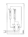
- FIG. 2 is a diagram illustrating the radio base station according to the embodiment.
- this radio base station 1 includes a plurality of antennas 2 and 3, a transmission unit 4, a reception unit 5, a downlink user data management unit 6, and uplink user data.
- a management unit 10, an SRS management unit 13, a resource determination unit 7, a resource notification unit 8, a transmission path state estimation unit 9, and a network communication unit 11 are provided.
- the transmission unit 4 transmits control signals such as downlink user data and RRC (Radio Resource Control) connection reset message, uplink user data / downlink user data allocation message to the radio terminal through the plurality of antennas 2 and 3. Send.
- the transmission unit 4 forms the directivity of the plurality of antennas 2 and 3 based on the state of the transmission path for each subcarrier estimated by the transmission path state estimation unit 9 and transmits downlink user data.
- the transmission unit 4 performs adaptive array transmission processing (weight processing) on the downlink user data according to the state of the transmission path, and forms the directivity of the antennas 2 and 3.
- the beam forming that directs the beam (the part that strongly receives / transmits the signal) to the desired communication partner and the direction of the undesired signal source or the direction in which interference is not desired
- null steering that directs the null (the part that hardly receives / transmits the signal).
- the receiving unit 5 receives a control signal including uplink user data, an SRS, an RRC connection reconfiguration completion message, and the like from the wireless terminal through the plurality of antennas 2 and 3.
- the downlink user data management unit 6 holds downlink user data received from a control center (not shown) through the network communication unit 11.
- the uplink user data management unit 10 transmits the uplink user data received from the wireless terminal to a control center (not shown) through the network communication unit 11. Further, the uplink user data management unit 10 outputs the DRS included in the received uplink user data to the transmission path state estimation unit 9.
- the SRS management unit 13 outputs the SRS received from the wireless terminal to the transmission path state estimation unit 9.
- the resource determination unit 7 periodically transmits the downlink user data to the radio terminal at least in a part of any downlink subframe DL. Determine as “first resource”.
- the resource determination unit 7 determines a part of the UpPTS (uplink part) in the switching subframe as a “second resource” for the wireless terminal to periodically transmit the SRS.
- the resource determination unit 7 determines at least a part of any uplink subframe UL as a “third resource” for periodically transmitting uplink user data including DRS for a predetermined period.
- the resource notifying unit 8 transmits uplink user data / downlink user data allocation information representing the determined first resource and third resource to the wireless terminal.
- the resource notification unit 8 transmits an RRC connection reconfiguration message representing the determined second resource to the wireless terminal.
- the resource notification unit 8 receives an RRC connection reconfiguration completion message from the wireless terminal.
- the transmission path state estimation unit 9 estimates the transmission path state based on SRS or DRS.
- the network communication unit 11 receives downlink user data from the control center through the network 12.
- the network communication unit 11 transmits uplink user data through the network 12 to the control center.
- FIG. 3 is a diagram illustrating the configuration of the wireless terminal according to the embodiment.
- the wireless terminal 51 includes a plurality of antennas 52, 53, a transmission unit 54, a reception unit 55, a user data management unit 57, and a sounding signal management unit 58.
- the receiving unit 55 receives control signals such as downlink user data and an RRC connection reconfiguration message through the plurality of antennas 52 and 53.
- the transmission unit 54 transmits control signals such as uplink user data and SRS, RRC connection reconfiguration completion message to the radio base station 1 through the plurality of antennas 52 and 53.
- the user data management unit 56 holds and manages downlink user data received from the radio base station 1 and uplink user data to be transmitted to the radio base station 1.
- the sounding signal management unit 58 When the sounding signal management unit 58 receives the RRC connection reconfiguration message, the sounding signal management unit 58 allocates radio resources for transmitting the SRS based on the RRC connection reconfiguration message. Thereafter, the sounding signal management unit 58 transmits an RRC connection reconfiguration completion message. The sounding signal management unit 58 transmits the SRS using the assigned radio resource.
- FIG. 4 is a diagram illustrating a configuration of a frame transmitted in the wireless communication system according to the embodiment.
- the configuration of this frame is a configuration when (Uplink-downlink configuration) in LTE is “1”.
- one frame is transmitted in a time of 10 ms.
- One frame is divided into half frames.
- Each half frame includes a downlink subframe DL, a switching subframe S, two consecutive uplink subframes UL, and a downlink subframe DL in time order.
- the switching subframe S is composed of DwPTS (Downlink Pilot Timeslot), GP (Guard Period: guard period), and UpPTS (Uplink Pilot Timeslot: also called uplink part).
- UpPTS is composed of two symbols.
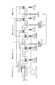
- FIG. 5 is a diagram for explaining the processing timing of the embodiment.
- radio base station 1 determines a second resource for periodically transmitting SRS in radio terminal 51 that is a transmission destination of downlink user data.
- the wireless terminal 51 determines a third resource for transmitting uplink user data including DRS.
- the radio base station 1 transmits uplink user data allocation information representing the determined third resource (shown in (1)).
- the wireless terminal 51 transmits uplink user data including DRS through the notified third resource in the (N-2) th frame (shown in (2)).
- the wireless base station 1 estimates the state of the transmission path with the wireless terminal 51 based on the DRS received in (2).
- the wireless base station 1 determines the second resource for periodically transmitting the SRS in the wireless terminal 51 that is the transmission destination of the downlink user data
- the wireless base station 1 forms the directivity of the plurality of antennas based on the estimated state of the transmission path.
- an RRC connection re-establishment message (indicating transmission start) representing the determined second resource is transmitted (shown in (5)).
- the wireless terminal 51 transmits an RRC connection reconfiguration (indicating transmission start) completion message (shown in (9)) to start the SRS transmission section.
- the radio base station 1 determines a third resource for the radio terminal 51 to transmit uplink user data including DRS, and allocates uplink user data representing the determined third resource Information is transmitted (shown in (3)).
- the wireless terminal 51 transmits uplink user data including DRS using the notified third resource (shown in (4)).
- the radio base station 1 determines at least a part of the downlink subframe DL as a first resource for transmitting downlink user data to the radio terminal.
- the radio base station 1 forms the directivity of the plurality of antennas based on the state of the transmission path estimated based on the DRS received in (4), and transmits the downlink user data through the first resource and the first Downlink user allocation information indicating that downlink resource data is included in the resource is transmitted (shown in (8)).
- the radio base station 1 determines the third resource for the radio terminal 51 to transmit the uplink user data including the DRS, and allocates the uplink user data representing the determined third resource. Information is transmitted (shown in (6)).
- the wireless terminal 51 transmits uplink user data including DRS using the notified third resource (shown in (7)).
- the radio base station 1 determines at least a part of the downlink subframe DL as a first resource for transmitting downlink user data to the radio terminal.
- the radio base station 1 forms the directivity of the plurality of antennas based on the state of the transmission path estimated based on the DRS received in (4), and transmits the downlink user data through the first resource and the first Downlink user allocation information indicating that downlink resource data is included in the resource is transmitted (shown in (8)).
- the wireless terminal 51 transmits an RRC connection reconfiguration completion message (shown in (9)).
- the radio base station 1 determines the radio terminal 51 and the radio terminal 51 based on the DRS received in (7) The state of the transmission line between is estimated.
- the radio base station 1 forms directivity of a plurality of antennas based on the estimated state of the transmission path, and transmits downlink user data (shown in (10)).
- the wireless terminal 51 transmits SRS through UpPTS (shown in (11)).
- the radio base station 1 estimates the state of the transmission path with the radio terminal 51 based on the received SRS.
- the radio base station 1 forms directivities of a plurality of antennas based on the estimated transmission path state, and the downlink user data is included in the first resource through the first resource. Is transmitted (shown in (12)).
- SRS transmission (11) by the wireless terminal 51 and downlink user data transmission (12) based on SRS by the wireless base station 1 are repeated.
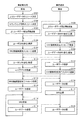
- FIG. 6 is a flowchart illustrating an operation procedure of the wireless communication system according to the embodiment.
- the resource determination unit 7 of the radio base station 1 transmits at least a part of the UL of any uplink subframe, so that the radio terminal 51 transmits uplink user data including DRS.
- the third resource is determined (step S101).
- the resource determination unit 7 of the radio base station 1 determines any resource in the UpPTS of the switching subframe S as a second resource for the radio terminal 51 to periodically transmit SRS (step S102). ).
- the resource notification unit 8 of the radio base station 1 transmits uplink user data allocation information representing the determined third resource as shown in (1) of FIG. 5 (step S103).
- the user data management unit 57 of the wireless terminal 51 receives the uplink user data allocation information representing the third resource (step S104).
- the user data management unit 57 of the wireless terminal 51 transmits uplink user data including DRS using the third resource notified in step S104 (step S105). .
- the uplink user data management unit 10 of the radio base station 1 receives the uplink user data including the DRS (Step S106).
- the transmission path state estimation unit 9 of the wireless base station 1 estimates the state of the transmission path with the wireless terminal 51 based on the DRS received in step S106.
- the resource notification unit 8 of the radio base station 1 forms the directivities of the plurality of antennas 2 and 3 based on the estimated transmission path state, and determines the determined second as shown in (5) of FIG.
- An RRC connection reset message representing the resource is transmitted (step S107).
- the sounding signal management unit 58 of the wireless terminal 51 receives the RRC connection reset message (step S108).
- the user data management unit 57 of the wireless terminal 51 transmits the uplink user data including the DRS using the third resource notified in step S104 (step S109). .
- the uplink user data management unit 10 of the radio base station 1 receives the uplink user data including the DRS (Step S110).
- the resource determination unit 7 of the radio base station 1 determines at least a part of any downlink subframe DL as a first resource for transmitting downlink user data to the radio terminal 51.
- the transmitter 4 of the radio base station 1 forms the directivity of the plurality of antennas 2 and 3 based on the state of the transmission path estimated based on the DRS received in step S106, and is shown by (8) in FIG.
- the downlink user data and downlink user data allocation information indicating that the downlink resource data is included in the first resource are transmitted through the first resource (step S111).
- the receiving unit 55 of the wireless terminal 51 receives downlink user data and downlink user data allocation information through the plurality of antennas 52 and 53 (step S112).
- the sounding signal management unit 58 of the wireless terminal 51 transmits an RRC connection reconfiguration completion message (step S113).
- the resource notification unit 8 of the radio base station 1 receives the RRC connection reconfiguration completion message (step S114).
- the transmission path state estimation unit 9 of the wireless base station 1 estimates the state of the transmission path with the wireless terminal 51 based on the DRS received in step S110.
- the transmission unit 4 of the radio base station 1 forms the directivity of the plurality of antennas 2 and 3 based on the estimated transmission path state, and transmits downlink user data as indicated by (10) in FIG. (Step S115).
- the receiving unit 55 of the wireless terminal 51 receives downlink user data through the plurality of antennas 52 and 53 (step S116).
- the sounding signal management unit 58 of the wireless terminal 51 transmits the SRS using the second resource notified in step S108 (step S117).
- the SRS management unit 13 of the radio base station 1 receives the SRS (step S118).
- the transmission path state estimation unit 9 of the wireless base station 1 estimates the state of the transmission path with the wireless terminal 51 based on the SRS received in step S118.
- the transmitter 4 of the radio base station 1 forms the directivity of the plurality of antennas 2 and 3 based on the estimated transmission path state, and as shown in (12) of FIG. Data allocation information is transmitted (step S119).
- the receiving unit 55 of the wireless terminal 51 receives downlink user data through the plurality of antennas 52 and 53 (step S120).
- the radio base station includes the first resource for transmitting downlink user data, the second resource for receiving SRS, and the uplink including DRS.
- a third resource for receiving user data is determined, and a control message (RRC connection reconfiguration completion message) representing the second resource is transmitted to the wireless terminal.
- the radio base station estimates the transmission path state using the DRS included in the received uplink user data as a sounding signal, and forms the directivity of a plurality of antennas based on the estimated transmission path state, Send a control message to the wireless terminal. Therefore, occurrence of transmission / reception errors of the control message can be suppressed.
- the radio base station uses the received SRS as a sounding signal for estimating the transmission path state.
- the radio base station uses DRS for transmitting control data necessary for transmitting SRS, while using SRS for transmitting user data.
- DRS digital versatile radio Service
- FIG. 7 is a diagram for explaining the processing timing of the modified example of the embodiment.
- the process shown in FIG. 7 is different from that shown in FIG. 5 as follows.
- the radio base station 1 determines the first resource every time before transmitting downlink user data, but in FIG. 7, the radio base station 1 periodically transmits the same first user data to the downlink user data.
- the first resource is first determined once and transmitted to the wireless terminal 51.
- the radio base station 1 includes a first resource that periodically transmits downlink user data after a predetermined downlink subframe DL (that is, with a half frame as a period), and a downlink user.
- the second resource that periodically transmits the SRS (half frame period) and the downlink user data transmission destination wireless terminal 51 periodically transmits the uplink user data including the DRS. Therefore, a third resource to be transmitted is determined (shown in (1)) for a predetermined period (that is, only twice with a half frame as a cycle). Then, the radio base station 1 transmits uplink user data / downlink user data allocation information representing the determined first resource and third resource (shown in (2)).
- FIG. 8 is a flowchart showing an operation procedure of the wireless communication system according to the modification of the embodiment.
- the procedure shown in FIG. 8 is different from the operation procedure of FIG. 6 as follows.
- the resource determination unit 7 of the radio base station 1 determines the first resource and the second resource (steps S101 and S102), and the resource notification unit 8 of the radio base station 1 determines the third resource
- uplink user data allocation information representing resources is transmitted (step S103)
- the resource determination unit 7 of the radio base station 1 determines the first resource, the second resource, and the third resource
- the resource notification unit 8 of the radio base station 1 transmits uplink user data / downlink user data allocation information representing the determined first resource and third resource (step S203).
- the resource determination unit 7 of the radio base station 1 first determines the first resource only once, and periodically transmits the downlink user data through the first resource.
- the radio base station determines the third resource for receiving the uplink user data including the DRS, and notifies the determined third resource to the radio terminal.
- the present invention is not limited to this. Not what you want. If the radio base station has already received the uplink user data from the radio terminal, the DRS included in the uplink user data can be used for the estimation of the transmission path state. There is no need to decide.
- the resource determination unit determines a part of the UpPTS (uplink part) in the switching subframe as the second resource for the wireless terminal to periodically transmit the SRS, but the present invention is limited to this. It is not a thing.
- the resource determination unit may determine all of the UpPTS in the switching subframe as a second resource for the wireless terminal to periodically transmit SRS.
- the resource determination unit determines a part (for example, the last symbol) in the switching subframe or the uplink subframe as a second resource for the wireless terminal to periodically transmit the SRS. Also good.
- the present invention can be applied to a radio base station that estimates a transmission path based on a reference signal.
Landscapes
- Engineering & Computer Science (AREA)
- Signal Processing (AREA)
- Computer Networks & Wireless Communication (AREA)
- Mobile Radio Communication Systems (AREA)
- Radio Transmission System (AREA)
Abstract
Description
図1は、実施の形態の無線通信システムの構成を表わす図である。
図2は、実施の形態の無線基地局を表わす図である。
リソース決定部7は、下りユーザデータ管理部6が下りユーザデータを受けると、いずれかのダウンリンクサブフレームDL内の少なくとも一部を、無線端末への下りユーザデータを周期的に送信するための「第1のリソース」として決定する。リソース決定部7は、切替サブフレーム内のUpPTS(アップリンクパート)の一部を無線端末がSRSを周期的に送信するための「第2のリソース」として決定する。リソース決定部7は、いずれかのアップリンクサブフレームUL内の少なくとも一部を、DRSを含む上りユーザデータを所定の期間周期的に送信するための「第3のリソース」として決定する。
ネットワーク通信部11は、制御センターからネットワーク12を通じて下りユーザデータを受信する。ネットワーク通信部11は、制御センターへネットワーク12を通じて上りユーザデータを送信する。
図3は、実施の形態の無線端末の構成を表わす図である。
図4は、実施の形態の無線通信システムで伝送されるフレームの構成を表わす図である。
図5は、実施の形態の処理タイミングを説明するための図である。
図6は、実施の形態の無線通信システムの動作手順を表わすフローチャートである。
次に、無線基地局1の伝送路状態推定部9は、ステップS118で受信したSRSに基づいて、無線端末51との間の伝送路の状態を推定する。無線基地局1の送信部4は、推定した伝送路の状態に基づいて複数のアンテナ2,3の指向性を形成して、図5の(12)で示すように、下りユーザデータおよび下りユーザデータ割当情報を送信する(ステップS119)。
図7は、実施の形態の変形例の処理タイミングを説明するための図である。
図5では、無線基地局1は、下りユーザデータを送信する前ごとに、第1のリソースを決定したが、図7では、無線基地局1は、下りユーザデータを周期的に同一の第1のリソースを用いて送信することとし、最初に一度だけこの第1のリソースを決定して、無線端末51へ送信する。
(動作手順)
図8は、実施形態の変形例の無線通信システムの動作手順を表わすフローチャートである。
図6では、無線基地局1のリソース決定部7が、第1のリソースおよび第2のリソースを決定し(ステップS101,102)、無線基地局1のリソース通知部8が、決定した第3のリソースを表わす上りユーザデータ割当情報を送信したが(ステップS103)、図8では、無線基地局1のリソース決定部7が、第1のリソース、第2のリソースおよび第3のリソースを決定し(ステップ201,202)、無線基地局1のリソース通知部8が、決定した第1のリソースおよび第3のリソースを表わす上りユーザデータ/下りユーザデータ割当情報を送信する(ステップS203)。なお、無線基地局1のリソース決定部7は、最初に一度だけ第1のリソースを決定し、この第1のリソースを通じて、周期的に下りユーザデータを送信する。
本発明は、上記の実施の形態に限定されるものではなく、たとえば以下のような変形例も含む。
実施の形態では、無線基地局が、DRSを含む上りユーザデータを受信するための第3のリソースを決定し、その決定した第3のリソースを無線端末に通知することとしたが、これに限定するものではない。無線基地局が、すでにその無線端末から上りユーザデータを受信している場合には、その上りユーザデータに含まれるDRSを伝送路状態の推定に用いることができるので、新たに第3のリソースを決定する必要はない。
実施の形態では、リソース決定部は、切替サブフレーム内のUpPTS(アップリンクパート)の一部を無線端末がSRSを周期的に送信するための第2のリソースとして決定したが、これに限定するものではない。
Claims (7)
- いずれかのダウンリンクサブフレーム内の少なくとも一部を、無線端末への下りユーザデータを送信するための第1のリソースとして決定し、切替サブフレーム内のアップリンクパートの少なくとも一部、またはアップリンクサブフレームの一部を、前記無線端末が第1のレファレンス信号を周期的に送信するための第2のリソースとして決定し、いずれかのアップリングサブフレーム内の少なくとも一部を、前記無線端末が、第2のレファレンス信号を含む上りユーザデータを所定の期間送信するための第3のリソースとして決定するリソース決定部と、
前記決定した第3のリソースを前記無線端末に通知するリソース通知部と、
前記無線端末から前記第3のリソースを通じて前記第2のレファレンス信号を含む上りユーザデータを受信すると、前記受信した上りユーザデータに含まれる前記第2のレファレンス信号に基づいて前記無線端末との間の伝送路の状態を推定する伝送路状態推定部とを備え、
前記リソース通知部は、前記推定した伝送路の状態に基づいてアンテナの指向性を形成して、前記第1のリソースを通じて、前記決定した第2のリソースを前記無線端末に通知するための制御メッセージを送信する、無線基地局。 - 前記無線基地局は、LTE(Long Term Evolution)方式の通信システムにおける無線基地局であり、
前記アップリンクパートは、UpPTS(Uplink Pilot Timeslot)である、請求項1に記載の無線基地局。 - 前記リソース決定部は、Uplink-downlink configurationが「1」のフレーム構成に従って、前記第1のリソース、前記第2のリソース、および前記第3のリソースを決定する、請求項2に記載の無線基地局。
- 前記伝送路状態推定部は、前記無線端末から前記第2のリソースを通じて送信される前記第1のレファレンス信号を受信してからは、前記第1のレファレンス信号に基づいて前記無線端末との間の伝送路の状態を推定し、
前記無線基地局は、前記第1のレファレンス信号に基づいて推定した伝送路の状態に基づいて前記アンテナの指向性を形成して、前記第1のリソースを通じて前記下りユーザデータを送信する送信部をさらに備える、請求項1に記載の無線基地局。 - 前記無線基地局は、LTE(Long Term Evolution)方式の通信システムにおける無線基地局であり、
前記アップリンクパートは、UpPTS(Uplink Pilot Timeslot)である、請求項4に記載の無線基地局。 - 前記リソース決定部は、Uplink-downlink configurationが「1」のフレーム構成に従って、前記第1のリソース、前記第2のリソース、および前記第3のリソースを決定する、請求項5に記載の無線基地局。
- いずれかのダウンリンクサブフレーム内の少なくとも一部を、無線端末への下りユーザデータを送信するための第1のリソースとして決定し、切替サブフレーム内のアップリンクパートの少なくとも一部、またはアップリンクサブフレームの一部を、前記無線端末が第1のレファレンス信号を周期的に送信するための第2のリソースとして決定し、いずれかのアップリングサブフレーム内の少なくとも一部を、前記無線端末が、第2のレファレンス信号を含む上りユーザデータを所定の期間送信するための第3のリソースとして決定するステップと、
前記決定した第3のリソースを前記無線端末に通知するステップと、
前記無線端末から前記第3のリソースを通じて前記第2のレファレンス信号を含む上りユーザデータを受信すると、前記受信した上りユーザデータに含まれる前記第2のレファレンス信号に基づいて前記無線端末との間の伝送路の状態を推定するステップとを備え、
前記通知するステップは、前記推定した伝送路の状態に基づいてアンテナの指向性を形成して、前記第1のリソースを通じて、前記決定した第2のリソースを前記無線端末に通知するための制御メッセージを送信する、無線通信方法。
Priority Applications (2)
| Application Number | Priority Date | Filing Date | Title |
|---|---|---|---|
| US13/814,495 US8995408B2 (en) | 2010-08-06 | 2011-08-05 | Wireless base station and wireless communication method |
| CN2011800386923A CN103081549A (zh) | 2010-08-06 | 2011-08-05 | 无线基站和无线通信方法 |
Applications Claiming Priority (2)
| Application Number | Priority Date | Filing Date | Title |
|---|---|---|---|
| JP2010178160A JP5583512B2 (ja) | 2010-08-06 | 2010-08-06 | 無線基地局および無線通信方法 |
| JP2010-178160 | 2010-08-06 |
Publications (1)
| Publication Number | Publication Date |
|---|---|
| WO2012018113A1 true WO2012018113A1 (ja) | 2012-02-09 |
Family
ID=45559608
Family Applications (1)
| Application Number | Title | Priority Date | Filing Date |
|---|---|---|---|
| PCT/JP2011/067945 Ceased WO2012018113A1 (ja) | 2010-08-06 | 2011-08-05 | 無線基地局および無線通信方法 |
Country Status (4)
| Country | Link |
|---|---|
| US (1) | US8995408B2 (ja) |
| JP (1) | JP5583512B2 (ja) |
| CN (1) | CN103081549A (ja) |
| WO (1) | WO2012018113A1 (ja) |
Families Citing this family (1)
| Publication number | Priority date | Publication date | Assignee | Title |
|---|---|---|---|---|
| CN107182092B (zh) * | 2016-03-11 | 2023-10-17 | 中兴通讯股份有限公司 | 信道探测信号srs的发送方法及装置 |
Citations (2)
| Publication number | Priority date | Publication date | Assignee | Title |
|---|---|---|---|---|
| WO2008093952A2 (en) * | 2007-02-02 | 2008-08-07 | Lg Electronics Inc. | Antenna switching method and method for transmitting and receiving signals for the same |
| WO2009087182A2 (en) * | 2008-01-08 | 2009-07-16 | Nokia Siemens Networks Oy | Sounding reference signal arrangement |
Family Cites Families (13)
| Publication number | Priority date | Publication date | Assignee | Title |
|---|---|---|---|---|
| US20060056350A1 (en) * | 2004-09-16 | 2006-03-16 | Love Robert T | Method and apparatus for uplink communication in a cellular communication system |
| KR20080077755A (ko) * | 2007-02-21 | 2008-08-26 | 삼성전자주식회사 | 다중 안테나 시스템에서 신호 보정 장치 및 방법 |
| WO2009059555A1 (en) * | 2007-11-02 | 2009-05-14 | Da Tang Mobile Communications Equipment Co., Ltd. | Time division duplexing data transmitting method,apparatus and system |
| US8780790B2 (en) * | 2008-01-07 | 2014-07-15 | Qualcomm Incorporated | TDD operation in wireless communication systems |
| JP2009253910A (ja) | 2008-04-10 | 2009-10-29 | Sharp Corp | 無線通信システム、送信装置、受信装置および伝播路推定方法 |
| CN101572896B (zh) * | 2008-04-29 | 2011-01-26 | 大唐移动通信设备有限公司 | 一种配置上行探测参考信号的方法和装置 |
| CN101615928B (zh) * | 2008-06-25 | 2016-05-18 | 三星电子株式会社 | Lte系统中传输srs信令的方法和装置 |
| CN101335969B (zh) * | 2008-08-01 | 2012-11-28 | 中兴通讯股份有限公司 | 一种时分双工系统上行信道测量参考信号的发送方法 |
| EP2316183A4 (en) * | 2008-08-11 | 2014-07-30 | Nokia Corp | METHOD AND DEVICE FOR PROVIDING BUNDLED TRANSMISSIONS |
| JP5345688B2 (ja) * | 2008-08-12 | 2013-11-20 | テレフオンアクチーボラゲット エル エム エリクソン(パブル) | 通信システムにおける方法及び装置 |
| US8488535B2 (en) * | 2008-11-04 | 2013-07-16 | Nokia Corporation | Apparatus and method to allocate communication resources for an aperiodic data packet in a communication system |
| US20120113875A1 (en) * | 2009-01-27 | 2012-05-10 | Nokia Corporation | Method and apparatus for dynamically modifying a transmission frame |
| US8867495B2 (en) * | 2009-03-20 | 2014-10-21 | Qualcomm Incorporated | Feedback mechanisms for beamforming operation |
-
2010
- 2010-08-06 JP JP2010178160A patent/JP5583512B2/ja not_active Expired - Fee Related
-
2011
- 2011-08-05 CN CN2011800386923A patent/CN103081549A/zh active Pending
- 2011-08-05 US US13/814,495 patent/US8995408B2/en not_active Expired - Fee Related
- 2011-08-05 WO PCT/JP2011/067945 patent/WO2012018113A1/ja not_active Ceased
Patent Citations (2)
| Publication number | Priority date | Publication date | Assignee | Title |
|---|---|---|---|---|
| WO2008093952A2 (en) * | 2007-02-02 | 2008-08-07 | Lg Electronics Inc. | Antenna switching method and method for transmitting and receiving signals for the same |
| WO2009087182A2 (en) * | 2008-01-08 | 2009-07-16 | Nokia Siemens Networks Oy | Sounding reference signal arrangement |
Also Published As
| Publication number | Publication date |
|---|---|
| US20130176977A1 (en) | 2013-07-11 |
| CN103081549A (zh) | 2013-05-01 |
| US8995408B2 (en) | 2015-03-31 |
| JP2012039415A (ja) | 2012-02-23 |
| JP5583512B2 (ja) | 2014-09-03 |
Similar Documents
| Publication | Publication Date | Title |
|---|---|---|
| US9629086B2 (en) | Wireless communication device and wireless communication method | |
| JPWO2022044287A5 (ja) | 端末、無線通信方法、基地局及びシステム | |
| JP5596452B2 (ja) | 無線基地局および無線通信方法 | |
| US20210337416A1 (en) | Control information transmission method and apparatus | |
| EP3364675B1 (en) | Method and device for processing discovery message | |
| WO2018028675A1 (zh) | 随机接入信号配置方法、装置、设备、系统和存储介质 | |
| US20250365057A1 (en) | Method and apparatus for sidelink communication | |
| CN111510190A (zh) | 一种波束处理方法和基站 | |
| WO2022105904A1 (zh) | 传输处理方法、装置及通信设备 | |
| US8989126B2 (en) | Wireless base station and wireless communication method | |
| JP5583512B2 (ja) | 無線基地局および無線通信方法 | |
| JP5766338B2 (ja) | 無線端末および無線通信方法 | |
| WO2018040894A1 (zh) | 干扰处理方法及基站和计算机存储介质 | |
| CN113273098B (zh) | 一种信号传输方法、相关设备及系统 | |
| EP3576474B1 (en) | Information transmission method and device, information processing method and device | |
| JP5718597B2 (ja) | 無線基地局、無線端末および無線通信方法 | |
| US9203481B2 (en) | Radio base station and communication control method including a request to stop transmission of a reference signal at a predetermined timing | |
| KR102956116B1 (ko) | 피드백 채널 할당 및 송신 방법 및 디바이스 | |
| JP5710049B2 (ja) | 無線端末、無線通信方法、および送信プログラム | |
| CN118487726A (zh) | 信号传输方法、装置及终端 | |
| JPWO2022176157A5 (ja) | 端末、無線通信方法、基地局及びシステム | |
| KR20150008317A (ko) | 반송파 집적 동작시 동시 전송 방식 적용을 위한 셀 구성 변경 방법 및 그 방법을 수행하는 이동 통신 시스템과 디지털 신호 처리 장치 |
Legal Events
| Date | Code | Title | Description |
|---|---|---|---|
| WWE | Wipo information: entry into national phase |
Ref document number: 201180038692.3 Country of ref document: CN |
|
| 121 | Ep: the epo has been informed by wipo that ep was designated in this application |
Ref document number: 11814738 Country of ref document: EP Kind code of ref document: A1 |
|
| NENP | Non-entry into the national phase |
Ref country code: DE |
|
| WWE | Wipo information: entry into national phase |
Ref document number: 13814495 Country of ref document: US |
|
| 122 | Ep: pct application non-entry in european phase |
Ref document number: 11814738 Country of ref document: EP Kind code of ref document: A1 |