WO2012017668A1 - Gas pressure regulating valve - Google Patents
Gas pressure regulating valve Download PDFInfo
- Publication number
- WO2012017668A1 WO2012017668A1 PCT/JP2011/004439 JP2011004439W WO2012017668A1 WO 2012017668 A1 WO2012017668 A1 WO 2012017668A1 JP 2011004439 W JP2011004439 W JP 2011004439W WO 2012017668 A1 WO2012017668 A1 WO 2012017668A1
- Authority
- WO
- WIPO (PCT)
- Prior art keywords
- pressure
- valve body
- valve
- seal
- passage
- Prior art date
Links
Images


Classifications
-
- F—MECHANICAL ENGINEERING; LIGHTING; HEATING; WEAPONS; BLASTING
- F02—COMBUSTION ENGINES; HOT-GAS OR COMBUSTION-PRODUCT ENGINE PLANTS
- F02M—SUPPLYING COMBUSTION ENGINES IN GENERAL WITH COMBUSTIBLE MIXTURES OR CONSTITUENTS THEREOF
- F02M21/00—Apparatus for supplying engines with non-liquid fuels, e.g. gaseous fuels stored in liquid form
- F02M21/02—Apparatus for supplying engines with non-liquid fuels, e.g. gaseous fuels stored in liquid form for gaseous fuels
- F02M21/0218—Details on the gaseous fuel supply system, e.g. tanks, valves, pipes, pumps, rails, injectors or mixers
- F02M21/023—Valves; Pressure or flow regulators in the fuel supply or return system
- F02M21/0239—Pressure or flow regulators therefor
-
- F—MECHANICAL ENGINEERING; LIGHTING; HEATING; WEAPONS; BLASTING
- F16—ENGINEERING ELEMENTS AND UNITS; GENERAL MEASURES FOR PRODUCING AND MAINTAINING EFFECTIVE FUNCTIONING OF MACHINES OR INSTALLATIONS; THERMAL INSULATION IN GENERAL
- F16K—VALVES; TAPS; COCKS; ACTUATING-FLOATS; DEVICES FOR VENTING OR AERATING
- F16K31/00—Actuating devices; Operating means; Releasing devices
- F16K31/02—Actuating devices; Operating means; Releasing devices electric; magnetic
- F16K31/06—Actuating devices; Operating means; Releasing devices electric; magnetic using a magnet, e.g. diaphragm valves, cutting off by means of a liquid
-
- G—PHYSICS
- G05—CONTROLLING; REGULATING
- G05D—SYSTEMS FOR CONTROLLING OR REGULATING NON-ELECTRIC VARIABLES
- G05D7/00—Control of flow
- G05D7/06—Control of flow characterised by the use of electric means
- G05D7/0617—Control of flow characterised by the use of electric means specially adapted for fluid materials
- G05D7/0629—Control of flow characterised by the use of electric means specially adapted for fluid materials characterised by the type of regulator means
- G05D7/0635—Control of flow characterised by the use of electric means specially adapted for fluid materials characterised by the type of regulator means by action on throttling means
-
- F—MECHANICAL ENGINEERING; LIGHTING; HEATING; WEAPONS; BLASTING
- F02—COMBUSTION ENGINES; HOT-GAS OR COMBUSTION-PRODUCT ENGINE PLANTS
- F02M—SUPPLYING COMBUSTION ENGINES IN GENERAL WITH COMBUSTIBLE MIXTURES OR CONSTITUENTS THEREOF
- F02M21/00—Apparatus for supplying engines with non-liquid fuels, e.g. gaseous fuels stored in liquid form
- F02M21/02—Apparatus for supplying engines with non-liquid fuels, e.g. gaseous fuels stored in liquid form for gaseous fuels
- F02M21/0218—Details on the gaseous fuel supply system, e.g. tanks, valves, pipes, pumps, rails, injectors or mixers
- F02M21/0245—High pressure fuel supply systems; Rails; Pumps; Arrangement of valves
-
- F—MECHANICAL ENGINEERING; LIGHTING; HEATING; WEAPONS; BLASTING
- F16—ENGINEERING ELEMENTS AND UNITS; GENERAL MEASURES FOR PRODUCING AND MAINTAINING EFFECTIVE FUNCTIONING OF MACHINES OR INSTALLATIONS; THERMAL INSULATION IN GENERAL
- F16K—VALVES; TAPS; COCKS; ACTUATING-FLOATS; DEVICES FOR VENTING OR AERATING
- F16K1/00—Lift valves or globe valves, i.e. cut-off apparatus with closure members having at least a component of their opening and closing motion perpendicular to the closing faces
- F16K1/30—Lift valves or globe valves, i.e. cut-off apparatus with closure members having at least a component of their opening and closing motion perpendicular to the closing faces specially adapted for pressure containers
- F16K1/304—Shut-off valves with additional means
-
- F—MECHANICAL ENGINEERING; LIGHTING; HEATING; WEAPONS; BLASTING
- F16—ENGINEERING ELEMENTS AND UNITS; GENERAL MEASURES FOR PRODUCING AND MAINTAINING EFFECTIVE FUNCTIONING OF MACHINES OR INSTALLATIONS; THERMAL INSULATION IN GENERAL
- F16K—VALVES; TAPS; COCKS; ACTUATING-FLOATS; DEVICES FOR VENTING OR AERATING
- F16K31/00—Actuating devices; Operating means; Releasing devices
- F16K31/02—Actuating devices; Operating means; Releasing devices electric; magnetic
- F16K31/06—Actuating devices; Operating means; Releasing devices electric; magnetic using a magnet, e.g. diaphragm valves, cutting off by means of a liquid
- F16K31/0644—One-way valve
- F16K31/0655—Lift valves
-
- G—PHYSICS
- G05—CONTROLLING; REGULATING
- G05D—SYSTEMS FOR CONTROLLING OR REGULATING NON-ELECTRIC VARIABLES
- G05D16/00—Control of fluid pressure
- G05D16/20—Control of fluid pressure characterised by the use of electric means
-
- H—ELECTRICITY
- H01—ELECTRIC ELEMENTS
- H01M—PROCESSES OR MEANS, e.g. BATTERIES, FOR THE DIRECT CONVERSION OF CHEMICAL ENERGY INTO ELECTRICAL ENERGY
- H01M8/00—Fuel cells; Manufacture thereof
-
- H—ELECTRICITY
- H01—ELECTRIC ELEMENTS
- H01M—PROCESSES OR MEANS, e.g. BATTERIES, FOR THE DIRECT CONVERSION OF CHEMICAL ENERGY INTO ELECTRICAL ENERGY
- H01M8/00—Fuel cells; Manufacture thereof
- H01M8/04—Auxiliary arrangements, e.g. for control of pressure or for circulation of fluids
- H01M8/04082—Arrangements for control of reactant parameters, e.g. pressure or concentration
- H01M8/04201—Reactant storage and supply, e.g. means for feeding, pipes
- H01M8/04208—Cartridges, cryogenic media or cryogenic reservoirs
-
- F—MECHANICAL ENGINEERING; LIGHTING; HEATING; WEAPONS; BLASTING
- F02—COMBUSTION ENGINES; HOT-GAS OR COMBUSTION-PRODUCT ENGINE PLANTS
- F02D—CONTROLLING COMBUSTION ENGINES
- F02D19/00—Controlling engines characterised by their use of non-liquid fuels, pluralities of fuels, or non-fuel substances added to the combustible mixtures
- F02D19/02—Controlling engines characterised by their use of non-liquid fuels, pluralities of fuels, or non-fuel substances added to the combustible mixtures peculiar to engines working with gaseous fuels
- F02D19/026—Measuring or estimating parameters related to the fuel supply system
- F02D19/027—Determining the fuel pressure, temperature or volume flow, the fuel tank fill level or a valve position
-
- F—MECHANICAL ENGINEERING; LIGHTING; HEATING; WEAPONS; BLASTING
- F02—COMBUSTION ENGINES; HOT-GAS OR COMBUSTION-PRODUCT ENGINE PLANTS
- F02M—SUPPLYING COMBUSTION ENGINES IN GENERAL WITH COMBUSTIBLE MIXTURES OR CONSTITUENTS THEREOF
- F02M21/00—Apparatus for supplying engines with non-liquid fuels, e.g. gaseous fuels stored in liquid form
- F02M21/02—Apparatus for supplying engines with non-liquid fuels, e.g. gaseous fuels stored in liquid form for gaseous fuels
- F02M21/0218—Details on the gaseous fuel supply system, e.g. tanks, valves, pipes, pumps, rails, injectors or mixers
- F02M21/0221—Fuel storage reservoirs, e.g. cryogenic tanks
-
- H—ELECTRICITY
- H01—ELECTRIC ELEMENTS
- H01M—PROCESSES OR MEANS, e.g. BATTERIES, FOR THE DIRECT CONVERSION OF CHEMICAL ENERGY INTO ELECTRICAL ENERGY
- H01M2250/00—Fuel cells for particular applications; Specific features of fuel cell system
- H01M2250/20—Fuel cells in motive systems, e.g. vehicle, ship, plane
-
- Y—GENERAL TAGGING OF NEW TECHNOLOGICAL DEVELOPMENTS; GENERAL TAGGING OF CROSS-SECTIONAL TECHNOLOGIES SPANNING OVER SEVERAL SECTIONS OF THE IPC; TECHNICAL SUBJECTS COVERED BY FORMER USPC CROSS-REFERENCE ART COLLECTIONS [XRACs] AND DIGESTS
- Y02—TECHNOLOGIES OR APPLICATIONS FOR MITIGATION OR ADAPTATION AGAINST CLIMATE CHANGE
- Y02E—REDUCTION OF GREENHOUSE GAS [GHG] EMISSIONS, RELATED TO ENERGY GENERATION, TRANSMISSION OR DISTRIBUTION
- Y02E60/00—Enabling technologies; Technologies with a potential or indirect contribution to GHG emissions mitigation
- Y02E60/30—Hydrogen technology
- Y02E60/50—Fuel cells
-
- Y—GENERAL TAGGING OF NEW TECHNOLOGICAL DEVELOPMENTS; GENERAL TAGGING OF CROSS-SECTIONAL TECHNOLOGIES SPANNING OVER SEVERAL SECTIONS OF THE IPC; TECHNICAL SUBJECTS COVERED BY FORMER USPC CROSS-REFERENCE ART COLLECTIONS [XRACs] AND DIGESTS
- Y02—TECHNOLOGIES OR APPLICATIONS FOR MITIGATION OR ADAPTATION AGAINST CLIMATE CHANGE
- Y02T—CLIMATE CHANGE MITIGATION TECHNOLOGIES RELATED TO TRANSPORTATION
- Y02T10/00—Road transport of goods or passengers
- Y02T10/10—Internal combustion engine [ICE] based vehicles
- Y02T10/30—Use of alternative fuels, e.g. biofuels
-
- Y—GENERAL TAGGING OF NEW TECHNOLOGICAL DEVELOPMENTS; GENERAL TAGGING OF CROSS-SECTIONAL TECHNOLOGIES SPANNING OVER SEVERAL SECTIONS OF THE IPC; TECHNICAL SUBJECTS COVERED BY FORMER USPC CROSS-REFERENCE ART COLLECTIONS [XRACs] AND DIGESTS
- Y02—TECHNOLOGIES OR APPLICATIONS FOR MITIGATION OR ADAPTATION AGAINST CLIMATE CHANGE
- Y02T—CLIMATE CHANGE MITIGATION TECHNOLOGIES RELATED TO TRANSPORTATION
- Y02T90/00—Enabling technologies or technologies with a potential or indirect contribution to GHG emissions mitigation
- Y02T90/40—Application of hydrogen technology to transportation, e.g. using fuel cells
-
- Y—GENERAL TAGGING OF NEW TECHNOLOGICAL DEVELOPMENTS; GENERAL TAGGING OF CROSS-SECTIONAL TECHNOLOGIES SPANNING OVER SEVERAL SECTIONS OF THE IPC; TECHNICAL SUBJECTS COVERED BY FORMER USPC CROSS-REFERENCE ART COLLECTIONS [XRACs] AND DIGESTS
- Y10—TECHNICAL SUBJECTS COVERED BY FORMER USPC
- Y10T—TECHNICAL SUBJECTS COVERED BY FORMER US CLASSIFICATION
- Y10T137/00—Fluid handling
- Y10T137/7722—Line condition change responsive valves
- Y10T137/7758—Pilot or servo controlled
- Y10T137/7759—Responsive to change in rate of fluid flow
- Y10T137/776—Control by pressures across flow line valve
-
- Y—GENERAL TAGGING OF NEW TECHNOLOGICAL DEVELOPMENTS; GENERAL TAGGING OF CROSS-SECTIONAL TECHNOLOGIES SPANNING OVER SEVERAL SECTIONS OF THE IPC; TECHNICAL SUBJECTS COVERED BY FORMER USPC CROSS-REFERENCE ART COLLECTIONS [XRACs] AND DIGESTS
- Y10—TECHNICAL SUBJECTS COVERED BY FORMER USPC
- Y10T—TECHNICAL SUBJECTS COVERED BY FORMER US CLASSIFICATION
- Y10T137/00—Fluid handling
- Y10T137/7722—Line condition change responsive valves
- Y10T137/7758—Pilot or servo controlled
- Y10T137/7761—Electrically actuated valve
Definitions
- the present invention relates to a gas pressure regulating valve that regulates the pressure of high-pressure fuel gas to a pressure corresponding to an applied voltage or an applied current.
- Clean energy vehicles using fuel gas such as hydrogen gas and natural gas are known, such as fuel cell vehicles, hydrogen engine vehicles, and natural gas vehicles. These clean energy vehicles are equipped with a high-pressure tank and an injector or an electromagnetic pressure regulating valve, and move by supplying fuel gas stored in the high-pressure tank to a fuel cell or a gas engine by the injector or electromagnetic pressure regulating valve. ing.
- the injector and the electromagnetic pressure regulating valve can adjust the flow rate (or pressure) of the fuel gas supplied to the fuel cell or gas engine.
- the flow rate (or pressure) of the fuel gas can be adjusted by the injector or the electromagnetic pressure regulating valve. By adjusting the output, the output of the fuel cell or the gas engine is controlled.
- the injector can adjust the flow rate of the fuel gas by closing or opening its injection hole, and the flow rate of the fuel gas is changed according to the ratio of time for opening and closing the injection hole, that is, the duty ratio.
- the differential pressure between the upstream pressure and the output pressure of the injector is large, the flow rate of the fuel gas flowing when the injector injection hole is opened becomes extremely large, and the change in the flow rate of the fuel gas with respect to the change in the duty ratio of the injector becomes large.
- the flow rate gain (the value obtained by dividing the fuel gas flow rate by the duty ratio) becomes large and control becomes difficult.
- the upstream pressure of the injector becomes high, there is a problem that the duty control span from a small flow rate to a large flow rate becomes extremely narrow.
- the electromagnetic pressure regulating valve can adjust the flow rate of the fuel gas by adjusting the opening (opening area) of the valve passage. Therefore, when the upstream pressure of the electromagnetic pressure regulating valve increases, the differential pressure before and after the electromagnetic pressure regulating valve increases, and the flow rate of the flowing fuel gas changes greatly only by widening the opening slightly. The change in the flow rate of the fuel gas with respect to the change in the opening degree increases. Therefore, similarly to the injector, the pressure control of the fuel gas in the small flow rate region (low load state) is extremely difficult for the electromagnetic pressure regulating valve.
- two regulators are provided on the upstream side of the injector.
- the two regulators are arranged in series and depressurize the hydrogen gas supplied from the high-pressure tank in two stages.
- two regulators maintain the upstream pressure of the injector below a certain low pressure to reduce the differential pressure before and after the injector, thereby ensuring pressure controllability.
- the fuel cell system described in Patent Document 1 includes a plurality of regulators for reducing the pressure of the fuel gas in multiple stages.
- a plurality of regulators are provided, the number of components increases, and a space for providing these regulators is required. If it does so, the whole system will enlarge, cost will become high, and the weight of the whole system will also become large.
- the use limit pressure of the high-pressure tank must be set higher than the minimum operating pressure of the fuel cell or gas engine.
- the amount of fuel gas that can be used in the high-pressure tank is reduced as compared with the case where a single regulator is used, and the travel range of the automobile is reduced.
- a diaphragm system may be used as a sealing system for electromagnetic pressure regulating valves, etc., but diaphragm seals generally have a low pressure resistance, so when handling high-pressure fuel gas, the fuel gas may enter the atmosphere due to diaphragm damage. There is a risk of leakage. On the other hand, in the case of the O-ring method, fuel gas may leak into the atmosphere due to an unexpected external factor at high pressure.
- the present invention provides a gas pressure regulating valve capable of adjusting the secondary pressure to a target pressure more accurately and preventing leakage of fuel gas into the atmosphere even in a high-pressure fuel gas environment.
- the purpose is that.
- the gas pressure regulating valve of the present invention is provided at the opening of the tank, regulates and outputs the fuel gas filled in the tank, and has a housing having a valve passage connected to the primary port and the secondary port, A valve body that is provided in the housing and moves between a closed position for closing the valve passage and an open position for opening the valve passage to adjust the opening of the valve passage; and the valve body toward the closed position.
- a return spring that is biased, and a driving force that is disposed in the opening of the tank and is applied to the valve body so as to resist the biasing force of the return spring.
- a valve body driving means for moving the valve body toward the open position; a pressure feedback chamber formed in the housing and connected to the secondary port; and a gap between the valve body and the housing; A bearing member for slidingly supporting the body, and the bearing member Between the first and second seal members, which are respectively provided on the side and sealing both sides of the gap, and the valve body so as to be relatively movable from the base end of the valve body.
- a seal rod that forms a back pressure chamber connected to the primary port, and the first seal member receives the pressure in the pressure feedback chamber in a direction against the driving force, and according to the pressure to be received
- the valve body is moved toward the closed position, and is connected between the seal rod and the valve body to the secondary port from the back pressure chamber to the proximal end side of the valve body.
- a communication passage is formed, and the third seal member is provided between the communication passage and the back pressure chamber so as to seal between them.
- the secondary pressure can be regulated by changing the opening of the valve passage by changing the driving force of the valve body driving means.
- the secondary pressure is guided to the pressure feedback chamber, and the first seal member receives the secondary pressure of the pressure feedback chamber and moves the valve body toward the closed position.
- the first seal member moves the valve body toward the open position.
- the gas pressure regulating valve has high pressure controllability, and can modulate the high-pressure fuel gas to the target pressure more accurately.
- the back pressure chamber connected to the primary port since the back pressure chamber connected to the primary port is formed, the primary pressure acting on the valve body can be canceled by the pressure of the back pressure chamber, and the secondary pressure caused by the fluctuation of the primary pressure can be reduced. Variation can be suppressed. Thereby, the pressure controllability of the fuel gas can be improved, and the secondary pressure can be controlled more accurately than the conventional gas pressure regulating valve.
- a communication passage connected to the secondary port is formed between the seal rod and the valve body, and the space between the communication passage and the back pressure chamber is sealed by the third seal member. Therefore, even if the fuel gas in the back pressure chamber leaks from the back pressure chamber to the communication passage, the leaked fuel gas is guided to the secondary side such as the pressure feedback chamber. That is, the gas pressure regulating valve has a safety structure that guides the fuel gas leaked from the back pressure chamber to the secondary side, and can prevent the fuel gas from being discharged to the outside.
- the present invention is an in-tank type pressure regulating valve for gas, and a high pressure fuel gas can be regulated to a low pressure target pressure with a single valve.
- the configuration of the fuel gas supply system provided with the present invention can be greatly simplified, the installation space of the fuel gas supply system can be reduced, the cost can be reduced due to the reduction of the components, and the pressure loss in the fuel gas supply system Can be greatly reduced.
- the valve body can be smoothly moved by providing the bearing member, and the followability to the target pressure can be improved.
- the 1st and 2nd sealing member is provided in the both sides of the bearing member, and both sides of the gap
- a material that does not have corrosion resistance to the fuel gas can be used for the bearing member, and the number of materials that can be selected increases.
- by sealing the gap for example, even if the bearing member is lubricated with grease, the grease does not flow out of the gap. Thereby, while being able to implement
- the valve body includes a first pressure receiving surface that receives the primary pressure at the primary port toward the open position, and a second pressure receiving surface that receives the pressure of the back pressure chamber toward the closed position.
- the pressure receiving area of the first pressure receiving surface is the same as the pressure receiving area of the second pressure receiving surface.
- the primary pressure received by the valve body can be offset by the pressure in the back pressure chamber.
- variation of a primary pressure can be eliminated, and the pressure controllability of a secondary pressure can further be improved.
- the driving force of the valve body driving means can be reduced. Therefore, the gas pressure regulating valve can be reduced in size.
- the valve body receives a primary pressure at the primary port that receives a primary pressure toward the open position and a pressure at the back pressure chamber that receives a pressure toward the closed position.
- the pressure receiving area of the first pressure receiving surface is smaller than the pressure receiving area of the second pressure receiving surface.
- the acting force received by the valve body from the pressure in the back pressure chamber is greater than the acting force received by the valve body from the primary pressure. Therefore, since the force corresponding to the primary pressure acts on the valve body in the closing direction, even if the primary pressure suddenly fluctuates and increases, the valve body moves toward the open position and the valve passageway There is no such thing as opening. Therefore, when the valve body driving means does not operate, the valve passage can be tightly closed so that the fuel gas does not leak from the primary side to the secondary side.
- the first seal member is preferably a diaphragm seal
- the second seal member is preferably a low-pressure seal having a low frictional resistance
- the sliding friction by the first seal member can be eliminated by adopting the diaphragm seal as the first seal member. Moreover, sliding friction can be suppressed by adopting a low-pressure seal having a small frictional resistance as the second seal member.
- the valve body can be smoothly moved by suppressing the sliding friction acting on the valve body.
- the third seal member is preferably a high pressure seal having a small frictional resistance and a small difference between the starting resistance and the sliding resistance.
- the valve body can be moved smoothly and the responsiveness of the valve body can be improved. Moreover, since the high pressure seal is employed for the third seal member, the pressure resistance performance against the primary pressure is improved, and the limit pressure of the primary pressure supplied from the primary port can be improved.
- valve body when the applied voltage or applied current applied to the valve body driving means is zero, it is preferable that the valve body is of a normally closed type in which the valve body is moved to the closed position by the return spring.
- the valve passage can be cut off urgently by cutting off the applied voltage or applied current applied to the valve body driving means.
- a gas pressure regulating valve capable of adjusting the secondary pressure to a target pressure more accurately and preventing leakage of fuel gas into the atmosphere even in a high-pressure fuel gas environment. can do.
- the pressure regulating valves 1 and 1A to 1E according to the first to sixth embodiments of the present invention and the fuel gas supply system 2 including the same will be described with reference to the drawings described above.
- the concept of the direction such as up and down, left and right, and front and back in the embodiment is used for convenience of description, and the arrangement and direction of the configurations of the pressure regulating valves 1 and 1A to 1E and the fuel gas supply system 2 are described. It is not suggested to limit the direction to that direction.
- the pressure regulating valves 1 and 1A to 1E and the fuel gas supply system 2 described below are only one embodiment of the present invention, and the present invention is not limited to the embodiment and is within the scope of the invention. Can be added, deleted and changed.
- the fuel gas supply system 2 is connected to a high-pressure tank 3 in which fuel gas such as hydrogen gas or compressed natural gas is stored at high pressure.
- the fuel gas supply system 2 is connected to a fuel gas consumer such as a fuel cell or a gas engine, and adjusts the high-pressure fuel gas to a desired low pressure and supplies it to the fuel gas consumer.
- the fuel gas supply system 2 configured as described above includes an electromagnetic pressure regulating valve 1, a pressure sensor 4, and an arithmetic controller 5.
- the electromagnetic pressure regulating valve 1 is an in-tank container base valve, and is provided at the opening of the high-pressure tank 3.
- the electromagnetic pressure regulating valve 1 has a function of regulating high-pressure fuel gas.
- the electromagnetic pressure regulating valve 1 is connected to a fuel gas consumer via a supply path 2a, and a pressure sensor 4 is provided on the downstream side of the electromagnetic pressure regulating valve 1 in the supply path 2a.
- the pressure sensor 4 detects the pressure of the fuel gas flowing through the supply path 2a.
- the pressure sensor 4 is connected to the calculation controller 5 via the signal line 7, and a detected pressure signal corresponding to the detected pressure is input to the calculation controller 5.
- a target pressure command signal corresponding to the target pressure is input to the arithmetic controller 5 from an input means, a control device or the like (not shown).
- the arithmetic controller 5 calculates a difference between the target pressure command signal and the detected pressure signal, and flows a current having a magnitude corresponding to the difference to the electromagnetic pressure regulating valve 1.
- the electromagnetic pressure regulating valve 1 regulates high-pressure fuel gas to a constant pressure corresponding to the flowed current.
- an electromagnetic shut-off valve (not shown) may be added to the container base valve configured by the electromagnetic pressure regulating valve 1.
- the electromagnetic shut-off valve is a so-called electromagnetic on-off valve, and is provided upstream of the electromagnetic pressure regulating valve 1 in the supply path 2a.
- the electromagnetic shut-off valve has a function of opening and closing the supply path 2a in response to a signal transmitted thereto, and is used when an emergency shut-off is made between the high-pressure tank 3 and the fuel gas consumer.
- the electromagnetic pressure regulating valve 1 of the fuel gas supply system 2 configured as described above has various embodiments, and the configuration of the electromagnetic pressure regulating valve 1 will be described in detail below.
- the electromagnetic pressure regulating valve 1 of the first embodiment is merely an example of an electromagnetic pressure regulating valve provided in the fuel gas supply system 2, and some representatives are given after the description of the electromagnetic pressure regulating valve 1 of the first embodiment. Specific embodiments are also described in detail.
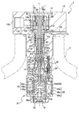
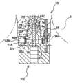
- the electromagnetic pressure regulating valve 1 according to the first embodiment shown in FIG.
- the housing 12 is substantially cylindrical.
- the lower end side of the housing 12 is inserted into the opening 3a of the high-pressure tank 3, and is sealed and attached to the opening 3a.
- the housing 12 has a valve body hole 12a and a secondary port 12b.
- the valve body hole 12a extends along the axis L1 extending in the vertical direction, and its cross section is circular.
- the valve body hole 12a penetrates the housing 12 in the vertical direction, and has openings on both the upper and lower sides.
- the secondary port 12 b is formed on the upper end side of the side surface of the housing 12 and is exposed outside the high-pressure tank 3.
- the housing 12 has a secondary side passage 12c orthogonal to the axis L1, and the secondary port 12b is connected to the valve element hole 12a via the secondary side passage 12c.
- the secondary port 12b is connected to a fuel gas consumer (see FIG. 1) via a supply path 2a (see FIG. 1).
- the housing 12 has a valve-side cap member 14 at the upper opening of the valve element hole 12a.
- the valve-side cap member 14 is formed in a generally bottomed cylindrical shape, and is fitted and inserted in a state of being sealed in the upper opening of the valve body hole 12a with its opening facing downward.
- an electromagnetic proportional solenoid 31 which will be described later, is screwed into the lower opening of the valve body hole 12a, and the housing 12 has a seat mounting portion 15 and a seat member 16 on the upper side of the electromagnetic proportional solenoid 31.
- the seat attachment portion 15 extends on the inner surface of the housing 12 over the entire circumference in the circumferential direction, and protrudes inward in the radial direction.
- the seat member 16 is disposed on the lower side of the seat attachment portion 15 in the valve body hole 12a and is in contact therewith.
- the sheet member 16 is substantially cylindrical and has a valve hole 16a formed along its axis (substantially coincident with the axis L1).
- the seat member 16 is fitted into the valve body hole 12a in a sealed state, and is sandwiched between the seat mounting portion 15 and the electromagnetic proportional solenoid 31.
- the front end portion 17a of the valve body 17 is seated on the seat member 16 disposed in the valve body hole 12a.
- the valve body 17 is generally formed in a bottomed cylindrical shape, and the outer periphery of the lower end portion 17a is tapered.
- the valve element 17 is inserted into the valve element hole 12a along the axis L1.
- a part of the tip end part 17a is pushed into the valve hole 16a and the seat It sits on the member 16 and closes the valve hole 16a.
- the valve body 17 has a flange 17b on the outer periphery on the base end side (upper side).
- the flange 17b is formed on the outer periphery of the valve body 17 over the entire circumference, and protrudes outward in the radial direction.
- the flange 17b is located on the upper opening side of the valve body hole 12a.
- the housing 12 has a seal mounting portion 18 at a position below the flange 17b on the inner surface and facing the flange 17b.
- the seal attachment portion 18 is formed on the inner surface of the housing 12 over the entire circumference in the circumferential direction, and protrudes inward in the radial direction.
- the seal mounting portion 18 and the flange 17b are separated from each other in the vertical direction, and a generally annular bearing member accommodating space 19 is formed between them.
- a bearing member 20 is accommodated in the bearing member accommodation space 19.
- the bearing member 20 is generally formed in a cylindrical shape, is externally mounted on the valve body 17 and is interposed between the valve body 17 and the housing 12.
- the bearing member 20 is configured by, for example, a ball guide, a ball bearing, or a sliding bearing, and supports the valve body 17 so that the valve body 17 can move in the vertical direction along the axis L ⁇ b> 1 with respect to the housing 12.
- the bearing member 20 is grease-lubricated so as to smooth the movement of the valve body 17 and improve durability.
- a diaphragm seal 21 and a low-pressure seal member 22 are provided on both upper and lower sides of the bearing member 20.
- the diaphragm seal 21 that is the first seal member is a so-called diaphragm, and has a generally annular shape.
- the outer edge portion of the diaphragm seal 21 is attached to the housing 12, and the inner edge portion is attached to the flange 17 b of the valve body 17.
- the housing 12 has a step 12d on the upper opening side of the valve body hole 12a on the inner surface thereof.
- the stepped portion 12d is formed on the inner surface over the entire circumference in the circumferential direction, and is configured in a stepped shape so as to expand outward in the radial direction.
- the opening end of the valve-side cap member 14 is in contact with the step portion 12d, and the diaphragm seal 21 is housed by sandwiching the outer edge portion of the diaphragm seal 21 between the valve-side cap member 14 and the step portion 12d. 12 is attached.
- a substantially cylindrical mounting member 23 is screwed onto the valve body 17 on the outer periphery of the base end portion and above the flange 17b.
- the lower end of the mounting member 23 is in contact with the upper surface of the flange 17b, and the diaphragm seal 21 is attached to the valve body 17 by sandwiching the inner edge portion of the diaphragm seal 21 between the flange 17b and the mounting member 23.
- the diaphragm seal 21 attached in this way is passed to the housing 12 and the valve body 17 and closes the space between the valve-side cap member 14 and the bearing member housing space 19 so as to be a pressure feedback chamber in the valve-side cap member 14. 25 is formed.
- the valve-side cap member 14 is formed with a through passage 14a penetrating in the radial direction so as to connect the inside and the outside.
- the pressure feedback chamber 25 and the secondary side passage 12c are connected by the through passage 14a. Yes.
- the low-pressure seal member 22 as the second seal member is a substantially annular O-ring, and is surface-treated with a resin or the like to reduce the frictional resistance.
- the low-pressure seal member 22 is attached to the seal attachment portion 18 and seals between the housing 12 and the valve body 17.
- a valve space 12e sandwiched between the seal mounting portion 18 and the seat member 16 is formed in the valve body hole 12a below the seal mounting portion 18, and the valve space 12e and the bearing member accommodating space 19 are formed by the low pressure seal member 22. Is sealed.
- the diaphragm seal 21 and the low-pressure seal member 22 close the upper side and the lower side of the bearing member accommodation space 19, and the bearing member accommodation space 19 is separated from other spaces formed in the housing 12.
- the housing 12 is formed with an atmosphere communication path 24 connected to the bearing member accommodation space 19, and the bearing member accommodation space 19 is open to the atmosphere via the atmosphere communication path 24.
- the fuel gas does not flow into the bearing member accommodating space 19, and the bearing member 20 is not exposed to the fuel gas.
- the grease of the bearing member 20 is not exposed to the fuel gas, and the grease does not leak into other spaces in the housing 12, such as the secondary side passage 12c and the valve space 12e. Therefore, it is possible to prevent the grease in the bearing member accommodating space 19 from being exhausted, and it is possible to maintain the state where the bearing member 20 is lubricated. Thereby, while being able to improve the durability of the bearing member 20, the valve body 17 can be moved smoothly. Further, it is possible to prevent grease from leaking out and being mixed into the fuel gas.
- the seal rod 26 is inserted into the valve body 17 provided in the housing 12 from the base end portion (that is, the upper end portion).
- the seal rod 26 is generally formed in a cylindrical shape, and forms a back pressure chamber 27 sandwiched between the bottom surface of the valve body 17 and the tip of the seal rod 26 in the valve body 17.
- a valve side communication passage 17e is formed at the distal end portion 17a of the valve body 17, and the back pressure chamber 27 is connected to the valve hole 16a through the valve side communication passage 17e.
- the seal rod 26 is supported by bringing the base end portion into contact with the ceiling surface of the valve-side cap member 14 and has a spring receiving portion 26a at the base end portion.
- the spring receiving portion 26a extends over the entire circumference in the outer periphery of the base end portion and protrudes outward in the radial direction.
- the spring receiving portion 26a faces the mounting member 23 of the valve body 17, and the return spring 28 is mounted between them in a compressed state.
- the return spring 28 is a compression coil spring and is sheathed on the proximal end side of the seal rod 26. The return spring 28 urges the valve body 17 toward the closed position (that is, in the closed position direction).
- An intermediate portion of the seal rod 26 has a smaller diameter than the distal end side and the proximal end side, and an annular communication passage 30 is formed between the outer peripheral surface of the seal rod 26 and the inner surface of the valve element 17.
- the distal end side and the proximal end side of the seal rod 26 have substantially the same diameter as the inner diameter of the valve body 17.
- the communication passage 30 is located on the upper side of the back pressure chamber 27, and its upper and lower sides are closed by the distal end side and the proximal end side of the seal rod 26.
- the valve body 17 has a distal end side passage 17c on the distal end side and a proximal end side passage 17d on the proximal end side, and the communication passage 30 is connected to the valve space 12e by the distal end side passage 17c, The side passage 17d is connected to the pressure return chamber 25.
- a seal groove 26b extending over the entire circumference in the circumferential direction is formed on the outer periphery on the tip side of the seal rod 26, and an annular high-pressure seal member 29 is fitted in the seal groove 26b.
- the high-pressure seal member 29 that is the third seal member is a high-pressure seal that has a small frictional resistance and a small difference between the starting resistance and the sliding resistance, and is, for example, an O-ring that is surface-treated with a fluororesin or the like.
- the high pressure seal member 29 seals between the valve body 17 and the seal rod 26.
- valve body 17 When the valve body 17 is pressed in the direction against the urging force of the return spring 28, that is, in the open position direction (open position direction), the valve body 17 is separated from the seat member 16 and opens the valve hole 16a.
- an electromagnetic proportional solenoid 31 is provided in the housing 12.
- the electromagnetic proportional solenoid 31 that is the valve body driving means is screwed into the opening end 12 f on the lower end side of the housing 12 and is disposed in the high-pressure tank 3.
- the electromagnetic proportional solenoid 31 includes a connecting member 32, and the connecting member 32 has a generally cylindrical shape.
- the upper end portion of the connecting member 32 is screwed into the opening end portion 12 f on the lower end side of the housing 12 and sandwiches the sheet member 16 together with the seat attachment portion 15.
- the connecting member 32 extends downward along the axis L ⁇ b> 1 and is disposed so that the inside thereof is connected to the valve hole 16 a of the seat member 16.
- a solenoid coil 33 is externally mounted on the lower end portion of the connecting member 32.
- the solenoid coil 33 is generally formed in a cylindrical shape, and extends downward along the axis L1.
- the solenoid coil 33 has a substantially cylindrical case 33a, in which a bobbin 33b and a coil wire 33c are provided.
- the bobbin 33b is also formed in a substantially cylindrical shape, and is wound around the coil wire 33c around the outer periphery of the bobbin 33b.
- the solenoid coil 33 configured as described above is positioned downward from the opening end 12f on the lower end side of the housing 12, and between the solenoid coil 33 and the opening end portion 12f on the lower end side of the housing 12.
- the spacer 34 is interposed.
- the spacer 34 is formed in a substantially cylindrical shape and is externally attached to the connecting member 32.
- a conductive wire 35 is provided inside the spacer 34 and the housing 12 so as to be inserted therethrough.
- the conductive wire 35 is connected to the arithmetic controller 5 (see FIG. 1) and the coil wire 33c, and can pass a current from the arithmetic controller 5 to the coil wire 33c.
- the solenoid coil 33 is excited by passing a current through the coil wire 33c.
- the lower opening end portion of the solenoid coil 33 configured in this way is closed by a solenoid-side cap member 36 that is fitted therein.
- the solenoid side cap member 36 has a generally bottomed cylindrical shape.
- the solenoid side cap member 36 is disposed in the solenoid coil 33 with the opening facing upward (that is, the connecting member 32 side).
- a movable iron core 37 is slidably inserted into the solenoid side cap member 36.
- the movable iron core 37 is formed in a substantially cylindrical shape, and is arranged so that the upper end thereof opposes the lower end of the connecting member 32.
- the movable iron core 37 is provided with a pressing rod 38.
- the pressing rod 38 is formed in a substantially cylindrical shape, and a base end portion (lower end portion) is screwed to the upper end portion of the movable iron core 37.
- the pressing rod 38 extends upward along the axis L ⁇ b> 1 and passes through the connecting member 32.
- the tip of the pressing rod 38 is formed in a partial spherical shape. The distal end portion of the pressing rod 38 reaches the valve hole 16 a of the seat member 16 and is in contact with the distal end portion 17 a of the valve body 17.
- the valve body 17 is pushed by the pressing rod 38 against the urging force of the return spring 28 in the open position direction.
- the hole 16a is opened.
- the open position is the position of the valve body 17 when the movable iron core 37 is attracted toward the connecting member 32.
- the movable iron core 37 has a spring seat 37a on its lower end side.
- the spring seat 37a is a recess formed along the axis of the movable iron core 37 (substantially coincides with the axis L1), into which a compression coil spring 39 is inserted.
- the compression coil spring 39 is attached in a compressed state between the movable iron core 37 and the solenoid side cap member 36.
- the compression coil spring 39 urges the movable iron core 37 toward the valve body 17 and presses the distal end portion of the pressing rod 38 against the distal end portion 17 a of the valve body 17.
- a primary port 41 is formed on the lower surface of the solenoid-side cap member 36.
- the primary port 41 is formed around the axis L ⁇ b> 1 and opens into the high-pressure tank 3.
- the solenoid side cap member 36 has a primary side passage 42 extending along the axis L1.
- the primary port 41 is connected to the solenoid side cap member 36 through the primary side passage 42. Yes.
- a primary side space 36 a sandwiched between the bottom surface of the solenoid side cap member 36 and the lower surface of the movable iron core 37 is formed.
- the primary side space 36 a is interposed via the primary side passage 42.
- a solenoid side communication path 43 is formed in the movable iron core 37.
- the solenoid side communication passage 43 has a communication portion 43a, a through portion 43b, and outer peripheral passages 43c and 43d.
- the communication portion 43a has an opening facing the spring seat 37a of the movable iron core 37, and extends upward along the axis L1 therefrom.
- the penetration part 43b is connected to the upper side of the communication part 43a, and extends from there to both sides in the radial direction.
- This penetration part 43b has penetrated the movable iron core 37 on the straight line, and both the opening is connected with the outer periphery channel
- the outer peripheral passages 43c and 43d are grooves formed on the outer periphery of the movable iron core 37 and extending upward from the opening of the through portion 43b.
- the outer peripheral passages 43 c and 43 d reach the upper end of the movable iron core 37.
- an inward flange 32 a is formed on the inner surface of the lower end side of the connecting member 32.
- the inward flange 32a is formed on the inner surface over the entire circumference in the circumferential direction and protrudes inward in the radial direction.
- the inner diameter of the inward flange 32a is slightly larger than the outer diameter of the pressing rod 38, and the pressing rod 38 is inserted through the inward flange 32a.
- a communication chamber 45 sandwiched between the upper ends of 37 is formed.
- the communication chamber 44 and the communication chamber 45 are connected to the valve hole 16a and the outer peripheral passages 43c and 43d, respectively.
- the communication chamber 44 and the communication chamber 45 are connected by a plurality of through passages 32b formed in the inward flange 32a. ing.
- the through passage 32b extends in parallel to the axis L1 so as to penetrate the inward flange 32a, and is arranged at equal intervals around the axis L1.
- the primary port 41 is connected to the valve hole 16a by the primary side passage 42, the solenoid side communication passage 43, the communication chamber 45, the through passage 32b, and the communication chamber 44 thus configured.
- the valve hole 16a is connected to the secondary port 12b by the valve space 12e, the distal end side passage 17c, the communication passage 30, the proximal end side passage 17d, the pressure feedback chamber 25, the through passage 14a, and the secondary side passage 12c.
- the primary side passage 42, solenoid side communication passage 43, communication chamber 44, through passage 32b, communication chamber 45, valve hole 16a, valve space 12e, distal end side passage 17c, communication passage 30, proximal end passage 17d, pressure feedback chamber 25, the through passage 14a and the secondary passage 12c constitute a valve passage 46, and the primary passage 41 and the secondary port 12b are connected by the valve passage 46.
- the primary port 41 and the secondary port 12b connected in this way are arranged so that the secondary port 12b is perpendicular to the primary port 41, and the electromagnetic pressure regulating valve 1 is an angle type pressure regulating valve. Yes.
- the electromagnetic pressure regulating valve 1 may be a linear (that is, in-line) pressure regulating valve, and in this case, the secondary port 12b is formed along the axis L1.
- the fuel gas in the high-pressure tank 3 is supplied to the primary port 41, and the fuel gas passes through the primary side passage 42, the solenoid side communication passage 43, the communication chamber 45, and the through passage 32b. And it is led to the valve hole 16 a through the communication chamber 44. Then, by separating the valve body 17 from the seat member 16 and opening the valve hole 16a, that is, by opening the valve passage 46, the fuel gas flows from the valve hole 16a to the valve space 12e, and the distal end side passage 17c, the communication passage 30, The gas is discharged from the secondary port 12b through the side passage 17d, the pressure return chamber 25, the through passage 14a, and the secondary passage 12c.
- valve passage 46 When the valve passage 46 is opened, an annular orifice is formed between the valve body 17 and the seat member 16.
- the fuel gas on the primary side that is on the primary port 41 side from the orifice is depressurized by the orifice and flows from the valve hole 16a to the secondary side that is on the secondary port 12b side. That is, the fuel gas having the primary pressure p 1 is reduced to the secondary pressure p 2 by the orifice.
- the fuel gas decompressed to the secondary pressure p 2 is guided to the pressure feedback chamber 25 through the communication passage 30 and the like as described above, and the diaphragm seal 21 is guided to the pressure feedback chamber 25 by the secondary pressure p 2.
- the primary pressure p 1 is guided to the back pressure chamber 27 through the valve-side communication passage 17e.
- the fuel gas of the primary pressure p 1 guided to the back pressure chamber 27 is prevented from leaking from the back pressure chamber 27 to the communication passage 30 by the high pressure seal member 29.
- the back pressure chamber 27 may leak into the communication passage 30.
- the communication passage 30 is connected to the secondary side such as the pressure return chamber 25 and the secondary port 12b, even if fuel gas leaks from the back pressure chamber 27 to the communication passage 30, the leaked fuel gas remains as it is. It flows to the next port 12b.
- the electromagnetic pressure regulating valve 1 is a valve having a safety structure that can return the fuel gas leaked from the primary side to the secondary side without leaking to the outside. Therefore, the fuel gas is not released to the outside of the electromagnetic pressure regulating valve 1. That is, fuel gas does not leak into the atmosphere.
- the pressure receiving area A1 of the pressure receiving surface P1 is determined according to the inner diameter r 1 of the seat member 16, that is, the seat diameter r 1, and the pressure receiving area A2 of the pressure receiving surface P2 is the inner diameter r 2 of the valve body 17, that is, the back pressure chamber 27. determined in accordance with a pore size of r 2.
- the sheet member 16 and the valve body 17 so that the seat diameter r 1 and a pore diameter r 2 is equal is formed. Therefore, in the electromagnetic pressure regulating valve 1 of the present embodiment, the acting force received by the pressure receiving surface P1 and the acting force received by the pressure receiving surface P2 are substantially the same and are canceled out.
- the upper and lower movable iron core 37, contact chamber 45 and the primary-side space 36a are respectively formed, in each room 45,36A, primary pressure p 1 is led, the movable iron core 37 has an upper end They are respectively receiving them primary pressure p 1 in the vertical direction (pressure receiving surface P3) and a lower end (pressure receiving surface P4).
- the movable iron core 37 is formed in a substantially cylindrical shape, the pressure receiving areas of the pressure receiving surfaces P3 and P4 are substantially the same, and the acting forces received by the pressure receiving surfaces P3 and P4 are offset.
- the valve body 17 has a larger diameter on the proximal end side than on the distal end side. Furthermore, the pressure receiving area A5 of the diaphragm seal 21 is larger than the pressure receiving areas A1 and A2. That is, the secondary pressure p 2 In the base end side of the valve body 17 toward the pressure receiving area of the pressure receiving surface P5 of the pressure receiving the closed position direction, in the front end side of the valve body 17 a secondary pressure p 2 Open It is larger than the pressure receiving area of the pressure receiving surface P6 that receives pressure in the position direction. Therefore, the valve body 17, the secondary pressure p 2 and the return spring 28 is pressed against the closed position direction, when no current flows through the solenoid coil 33, the valve body 17 is adapted to the closed position ing. That is, the electromagnetic pressure regulating valve 1 is configured as a normally closed valve. Therefore, the valve passage 46 can be urgently shut off by shutting off the current flowing through the solenoid coil 33.
- the fuel gas in the valve space 12e is guided to the pressure feedback chamber 25 through the distal end side passage 17c, the communication passage 30, and the proximal end side passage 17d, and further passes through the through passage 14a and the secondary passage 12c to the secondary port. It is discharged from 12b.
- the valve body 17 and diaphragm seal 21 receiving the secondary pressure p 2 of the fuel gas introduced to the pressure feedback chamber 25, the valve body 17, the secondary pressure receiving by the excitation force and the pressure receiving surface P5 of the movable iron core 37 is subjected acting force by p 2, and moves to the spring force is balanced the closed position direction or open position direction of the return spring 28.
- valve body 17 the opening degree of the valve passage 46 so that the force is balanced (i.e., opening degree of the orifice) by adjusting the adjust the secondary pressure p 2 of the fuel gas flowing through the valve space 12e.
- the secondary pressure p 2 becomes a pressure corresponding to the current flowing through the solenoid coil 33 (that is, the target pressure).
- the exciting force becomes larger than the acting force by the secondary pressure p 2 , and the valve body 17 moves in the direction away from the seat member 16 (that is, the open position direction). Then, the secondary pressure p 2 by spreading the opening of the valve passage 46 is increased. As a result, the valve body 17 moves to a position (opening) where the exciting force and the acting force due to the secondary pressure p 2 and the spring force of the return spring 28 are balanced to adjust the secondary pressure p 2 to the target pressure. . Therefore, even if the primary pressure p 1 fluctuates, the electromagnetic pressure regulating valve 1 can control the opening degree of the valve passage 46 in accordance with the fluctuation and adjust the secondary pressure p 2 to the target pressure.
- the electromagnetic pressure regulating valve 1 alone without vacuum beforehand a constant pressure of the primary pressure p 1, can be pressure regulated by depressurizing the high-pressure fuel gas to a predetermined low pressure, i.e. the target pressure. Therefore, the electromagnetic pressure regulating valve 1 has high pressure controllability.
- the primary pressure p 1 is guided to the back pressure chamber 27 to cancel the acting force received from the primary pressure p 1 at the pressure receiving surface P 1 and the pressure receiving surface P 2.
- the secondary pressure p 2 can be accurately controlled than traditional electromagnetic pressure regulating valve.
- canceling the action force received from the primary pressure p 1 it is possible to reduce the excitation force of the electromagnetic proportional solenoid 31, it is possible to miniaturize an electromagnetic pressure regulating valve 1.
- the diaphragm seal 21 sliding friction when the valve body 17 is moved can be eliminated. Moreover, by using the low-pressure seal member 22 having a low frictional resistance, sliding friction can be suppressed as much as possible. Thus, the valve body 17 can be smoothly moved by suppressing the sliding friction which acts on the valve body 17. Thus, it becomes possible to pressure quickly regulating the secondary pressure p 2 at the target pressure, thereby improving the responsiveness of the secondary pressure p 2. Further, by adopting the high-pressure sealing member 29, it is possible to improve the withstand voltage performance is improved with respect to the primary pressure p 1 of the electromagnetic pressure regulating valve 1, the limit pressure of the primary pressure p 1 supplied from the primary port 41.
- the electromagnetic pressure regulating valve 1 is an in-tank pressure regulating valve in which an electromagnetic proportional solenoid 31 is disposed in the high-pressure tank 3, and regulates high-pressure fuel gas to a low-pressure target pressure with a single valve. Can do.
- the configuration of the fuel gas supply system 2 can be greatly simplified, the installation space of the fuel gas supply system 2 can be reduced, the cost can be reduced due to the reduction in the number of components, and the high-pressure tank 3 and the fuel gas consumer Can significantly reduce the pressure loss.
- the electromagnetic pressure regulating valve 1 is an in-tank container base valve and has two functions of electromagnetic cutoff and electromagnetic pressure regulation. Therefore, an electromagnetic shut-off valve is not required on the upstream side of the electromagnetic pressure regulating valve 1, and the configuration as the container base valve is simplified, leading to significant pressure loss reduction and cost reduction.
- an energized portion such as the electromagnetic proportional solenoid 31 is disposed in the opening 3a of the high-pressure tank 3, that is, provided in the fuel gas, the electromagnetic pressure regulating valve 1 serves as a container base valve having an explosion-proof structure. .
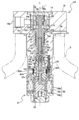
- the electromagnetic pressure regulating valve 1A according to the second embodiment of the present invention is similar in configuration to the electromagnetic pressure regulating valve 1 according to the first embodiment. Therefore, only the configuration different from that of the electromagnetic pressure regulating valve 1 of the first embodiment will be described with respect to the configuration of the electromagnetic pressure regulating valve 1A according to the second embodiment, and the same components are denoted by the same reference numerals and description thereof is omitted. To do.
- a primary port 41A and a primary side passage 42A are formed in the spacer 34A.
- the connecting member 32A has an outer peripheral groove 32c formed in the outer peripheral portion where the spacer 34A is sheathed.
- the outer circumferential groove 32c is formed in the outer circumferential portion of the connecting member 32A over the entire circumference.
- the primary side passage 42A is formed so as to connect the outer peripheral groove 32c and the primary port 41A.
- a plurality of spacer communication paths 32d extending in the radial direction are formed in the connection member 32A, and the outer peripheral groove 32c communicates with the communication chamber 44 through the plurality of spacer communication paths 32d.
- the primary side of the valve passage 46A is constituted by the primary port 41A, the primary side passage 42A, the outer peripheral groove 32c, the spacer communication passage 32d, and the communication chamber 45.
- the secondary side of the valve passage 46A has the same configuration as the secondary side of the valve passage 46 of the first embodiment.
- the electromagnetic pressure regulating valve 1A of the second embodiment has the same effects as the electromagnetic pressure regulating valve 1 according to the first embodiment.
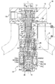
- the electromagnetic pressure regulating valves 1 ⁇ / b> B and 1 ⁇ / b> C according to the third and fourth embodiments of the present invention are the first and second, except that the pressure receiving area A ⁇ b> 1 and the pressure receiving area A ⁇ b> 2 are different. It is the same as that of the electromagnetic pressure regulating valves 1 and 1A according to the embodiment. Only that point will be described below.
- the valve body 17 and the housing 12 so that the seat diameter r 1 is smaller in diameter than the diameter r 2 of the back pressure chamber 27 is formed, the pressure receiving area A1 is smaller than the pressure receiving area A2 ing. Therefore, the valve body 17, acting force by the primary pressure p 1 in accordance with the area difference between the pressure receiving area A1 and the pressure receiving area A2 acts toward the closed position. Therefore, the speed toward the closed position of the valve body 17 when the current flowing through the solenoid coil 33 is interrupted is increased, and the interrupting performance is improved.
- the electromagnetic pressure regulating valves 1C, 1D can firmly close the valve passages 46, 46A so that the fuel gas does not leak from the primary side to the secondary side.
- the electromagnetic pressure regulating valves 1B and 1C of the third and fourth embodiments exhibit the same functions and effects as the electromagnetic pressure regulating valves 1 and 1A according to the first and second embodiments, respectively.
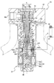
- the pressure regulating valve 1D according to the fifth embodiment is similar to the electromagnetic pressure regulating valve 1A according to the second embodiment, and includes a piezoelectric actuator 31D instead of the electromagnetic proportional solenoid 31 as shown in FIG.
- the piezoelectric actuator 31D which is a valve body driving means, is composed of a piezoelectric element (for example, a piezo element), generates a driving force according to the applied voltage, and moves the valve body 17 in the open position direction via the pressing rod 38. It moves to open the valve passage 46A. At this time, valve passage 46A is opened by opening corresponding to the driving force generated, regulating valve 1D can also allow pressure regulation of the secondary pressure p 2 in the pressure corresponding to the voltage applied to the piezoelectric actuator 31D It has become.
- the pressure regulating valve 1D according to the second embodiment has the same configuration as the electromagnetic pressure regulating valve 1A according to the second embodiment, and has the same effects.
- the pressure regulating valve 1E according to the sixth embodiment is similar to the electromagnetic pressure regulating valve 1A according to the second embodiment, and includes a force motor 31E instead of the electromagnetic proportional solenoid 31 as shown in FIG.
- the force motor 31E which is a valve body driving means, has a movable coil 62 inserted in a cylindrical permanent magnet 61.
- an exciting force corresponding to the current is generated.
- the movable coil 62 moves in the yoke 63.
- the valve body 17 is pushed in the open position direction by the push rod 38 provided integrally therewith, and the valve passage 46A is opened.
- valve passage 46A is opened by opening corresponding to the excitation force generated, regulating valve 1E also have to be able to pressure regulate the secondary pressure p 2 in the pressure corresponding to current flowing in the force motor 31E Yes.
- the pressure regulating valve 1E according to the sixth embodiment has the same configuration as the electromagnetic pressure regulating valve 1A according to the second embodiment, and has the same operational effects.
- the secondary pressure p 2 in the pressure feedback chamber 25 is pressure in the diaphragm seal 21 may not necessarily be a diaphragm seal may be a low-pressure sealing member such as an O-ring.
- the present invention can be applied to a gas pressure regulating valve that regulates the pressure of a high-pressure fuel gas to a pressure corresponding to a flowing current.
Abstract
Description
燃料ガス供給システム2は、水素ガスや圧縮天然ガス等の燃料ガスが高圧で貯蔵される高圧タンク3に繋がっている。燃料ガス供給システム2は、燃料電池やガスエンジン等の燃料ガス消費器に繋がっており、高圧の燃料ガスを所望の低圧に調圧して燃料ガス消費器に供給するようになっている。このように構成される燃料ガス供給システム2は、電磁式調圧弁1、圧力センサ4、及び演算制御器5を備えている。 [Fuel gas supply system]
The fuel
<電磁式調圧弁の構成>
図2に示す第1実施形態の電磁式調圧弁1は、ハウジング12を備えている。ハウジング12は、大略円筒状になっている。ハウジング12の下端側は、高圧タンク3の開口部3aに挿入され、該開口部3aにシールされて取付けられている。また、ハウジング12は、弁体孔12a及び二次ポート12bを有している。弁体孔12aは、上下方向に延びる軸線L1に沿って延在し、その断面が円形状になっている。弁体孔12aは、ハウジング12を上下方向に貫通し、その上下両側に開口を有している。二次ポート12bは、ハウジング12の側面の上端側に形成され、高圧タンク3外に表出している。また、ハウジング12は、軸線L1に直交する二次側通路12cを有しており、二次ポート12bは、二次側通路12cを介して弁体孔12aに繋がっている。また、二次ポート12bは、供給路2a(図1参照)を介して、燃料ガス消費器(図1参照)に繋がっている。 [First Embodiment]
<Configuration of electromagnetic pressure regulating valve>
The electromagnetic
以下では、図2を参照しながら電磁式調圧弁1の動作について説明する。電磁比例ソレノイド31のソレノイドコイル33に電流を流すと、可動鉄心37に励磁力が作用し、可動鉄心37が連結部材32の方へ引き付けられる。これにより、弁体17がシート部材16から離れて開位置方向に移動し、弁通路46が開く。弁通路46が開くことで、弁体17とシート部材16との間にオリフィス(図示せず)が形成され、燃料ガスがこのオリフィスにより二次圧p2に減圧されて弁空間12eに流れる。 <Operation of electromagnetic pressure regulator>
Below, operation | movement of the electromagnetic
本発明の第2実施形態に係る電磁式調圧弁1Aは、第1実施形態に係る電磁式調圧弁1と構成が類似している。そこで、第2実施形態に係る電磁式調圧弁1Aの構成に関して第1実施形態の電磁式調圧弁1と異なる構成についてだけ説明し、同一の構成については、同一の符合を付して説明を省略する。 [Second Embodiment]
The electromagnetic
本発明の第3及び第4実施形態に係る電磁式調圧弁1B,1Cは、図4及び図5に示すように、受圧面積A1及び受圧面積A2が異なる点を除いて、第1及び第2実施形態に係る電磁式調圧弁1,1Aと同様である。以下では、その点についてだけ説明する。 [Third and fourth embodiments]
As shown in FIGS. 4 and 5, the electromagnetic
第5実施形態に係る調圧弁1Dは、第2実施形態の電磁式調圧弁1Aに類似しており、図6に示すように電磁比例ソレノイド31に代えて圧電アクチュエータ31Dを備えている。弁体駆動手段である圧電アクチュエータ31Dは、圧電素子(例えば、ピエゾ素子)から成り、印加される印加電圧に応じた駆動力を発生し、押圧ロッド38を介して弁体17を開位置方向に動かして弁通路46Aを開くようになっている。この際、弁通路46Aは、発生する駆動力に応じた開度で開き、調圧弁1Dもまた、圧電アクチュエータ31Dに印加される印加電圧に応じた圧力に二次圧p2を調圧できるようになっている。 [Fifth Embodiment]
The
第6実施形態に係る調圧弁1Eは、第2実施形態の電磁式調圧弁1Aと類似しており、図7に示すように電磁比例ソレノイド31に代えてフォースモータ31Eを備えている。弁体駆動手段であるフォースモータ31Eは、円筒状の永久磁石61の中に可動コイル62が挿入されており、可動コイル62に電流を流すと電流に応じた励磁力が発生し、この励磁力により可動コイル62がヨーク63内を動くようになっている。可動コイル62が動くことでそれに一体的に設けられている押圧ロッド38によって弁体17が開位置方向に押されて弁通路46Aが開く。この際、弁通路46Aは、発生する励磁力に応じた開度で開き、調圧弁1Eもまたフォースモータ31Eに流される電流に応じた圧力に二次圧p2を調圧できるようになっている。 [Sixth Embodiment]
The
本実施形態では、圧力帰還室25の二次圧p2をダイアフラムシール21で受圧しているが、必ずしもダイアフラムシールでなくてもよく、Oリングなどの低圧シール部材であってもよい。 [Other Embodiments]
In this embodiment, the secondary pressure p 2 in the
1D,1E 調圧弁
3 タンク
12 ハウジング
12b 二次ポート
17 弁体
19 軸受部材収容空間
20 軸受部材
21 ダイアフラムシール
22 低圧シール部材
25 圧力帰還室
26 シールロッド
27 背圧力室
28 復帰用ばね
29 高圧シール部材
30 連絡通路
31 電磁比例ソレノイド
31D 圧電アクチュエータ
31E フォースモータ
41,41A 一次ポート
46,46A 弁通路 1, 1A to 1C Electromagnetic
Claims (6)
- タンクの開口部に設けられ、前記タンク内に充填された燃料ガスを調圧して出力するガス用調圧弁において、
一次ポートと二次ポートとに繋がる弁通路を有するハウジングと、
前記ハウジング内に設けられ、前記弁通路を閉じる閉位置と前記弁通路を開く開位置との間で移動して前記弁通路の開度を調整する弁体と、
前記弁体を閉位置の方に付勢する復帰用ばねと、
前記タンクの開口部内に配置され、印加される印加電圧又は印加電流に応じた駆動力を前記復帰用ばねの付勢に抗するように前記弁体に与えて前記弁体を前記開位置の方に移動させる弁体駆動手段と、
前記ハウジング内に形成され、前記二次ポートに繋がる圧力帰還室と、
前記弁体と前記ハウジングとの間隙に介在し、前記弁体を摺動支持する軸受部材と、
前記軸受部材の両側に夫々設けられ、前記間隙の両側を夫々封止する第1及び第2シール部材と、
前記弁体の基端から該弁体内に相対移動可能に挿入されて、前記弁体との間に前記一次ポートに繋がる背圧力室を形成するシールロッドと、を備え、
前記第1シール部材は、前記圧力帰還室の圧力を前記駆動力に抗する方向に受圧し、受圧する前記圧力に応じて前記弁体を前記閉位置の方に移動させるようになっており、
前記シールロッドと前記弁体との間には、前記背圧力室より前記弁体の基端側に前記二次ポートに繋がる連絡通路が形成され、
前記連絡通路と前記背圧力室との間には、その間を封止するように第3シール部材が設けられている、ガス用調圧弁。 In the gas pressure regulating valve that is provided at the opening of the tank and regulates and outputs the fuel gas filled in the tank,
A housing having a valve passage leading to the primary port and the secondary port;
A valve body that is provided in the housing and moves between a closed position that closes the valve passage and an open position that opens the valve passage, and adjusts the opening of the valve passage;
A return spring for biasing the valve body toward the closed position;
The valve body is disposed in the opening of the tank, and a driving force corresponding to the applied voltage or applied current is applied to the valve body so as to resist the urging force of the return spring, and the valve body is moved toward the open position. Valve body drive means for moving to
A pressure return chamber formed in the housing and connected to the secondary port;
A bearing member interposed in a gap between the valve body and the housing and slidingly supporting the valve body;
First and second seal members respectively provided on both sides of the bearing member and sealing both sides of the gap;
A seal rod which is inserted into the valve body from the proximal end of the valve body so as to be relatively movable and forms a back pressure chamber connected to the primary port between the valve body, and
The first seal member receives pressure in the pressure feedback chamber in a direction against the driving force, and moves the valve body toward the closed position according to the pressure received.
Between the seal rod and the valve body, a communication passage connected to the secondary port is formed on the base end side of the valve body from the back pressure chamber,
A gas pressure regulating valve in which a third seal member is provided between the communication passage and the back pressure chamber so as to seal between the communication passage and the back pressure chamber. - 前記弁体は、前記一次ポートにおける一次圧を前記開位置の方に受圧する第1受圧面と前記背圧力室の圧力を前記閉位置の方に受圧する第2受圧面とを有し、
前記第1受圧面の受圧面積は、前記第2受圧面の受圧面積と同一である、請求項1に記載のガス用調圧弁。 The valve body includes a first pressure receiving surface that receives a primary pressure at the primary port toward the open position, and a second pressure receiving surface that receives the pressure of the back pressure chamber toward the closed position;
2. The pressure regulating valve for gas according to claim 1, wherein a pressure receiving area of the first pressure receiving surface is the same as a pressure receiving area of the second pressure receiving surface. - 前記弁体は、前記一次ポートにおける一次圧を前記開位置の方に受圧する第1受圧面と前記背圧力室の圧力を前記閉位置の方に受圧する第2受圧面とを有し、
前記第1受圧面の受圧面積は、前記第2受圧面の受圧面積より小さい、請求項1に記載のガス用調圧弁。 The valve body includes a first pressure receiving surface that receives a primary pressure at the primary port toward the open position, and a second pressure receiving surface that receives the pressure of the back pressure chamber toward the closed position;
The pressure regulating valve for gas according to claim 1, wherein the pressure receiving area of the first pressure receiving surface is smaller than the pressure receiving area of the second pressure receiving surface. - 前記第1シール部材は、ダイアフラムシールであり、
前記第2シール部材は、摩擦抵抗が小さい低圧シールである、請求項1乃至3の何れか1つに記載のガス用調圧弁。 The first seal member is a diaphragm seal;
The pressure regulating valve for gas according to any one of claims 1 to 3, wherein the second seal member is a low-pressure seal having a small frictional resistance. - 前記第3シール部材は、摩擦抵抗が小さく、さらに始動抵抗と摺動抵抗との差が小さい高圧シールである、請求項1乃至4の何れか1つに記載のガス用調圧弁。 The gas pressure regulating valve according to any one of claims 1 to 4, wherein the third seal member is a high pressure seal having a small frictional resistance and a small difference between a starting resistance and a sliding resistance.
- 前記弁体駆動手段に印加される印加電圧又は印加電流がゼロのときは、前記復帰用ばねにより前記弁体を前記閉位置にするノーマルクローズ形になっている、請求項1乃至5の何れか1つに記載のガス用調圧弁。
6. The normally closed type according to any one of claims 1 to 5, wherein when the applied voltage or applied current applied to the valve body driving means is zero, the valve body is in the closed position by the return spring. The pressure regulating valve for gas as described in one.
Priority Applications (6)
| Application Number | Priority Date | Filing Date | Title |
|---|---|---|---|
| US13/812,009 US20130186487A1 (en) | 2010-08-06 | 2011-08-04 | Gas pressure regulating valve |
| KR1020137004770A KR20130052618A (en) | 2010-08-06 | 2011-08-04 | Gas pressure regulating valve |
| EP11814303.1A EP2602526A1 (en) | 2010-08-06 | 2011-08-04 | Gas pressure regulating valve |
| JP2012527604A JP5406993B2 (en) | 2010-08-06 | 2011-08-04 | Gas pressure regulator |
| CA2806513A CA2806513A1 (en) | 2010-08-06 | 2011-08-04 | Gas pressure regulating valve |
| CN2011800372494A CN103003606A (en) | 2010-08-06 | 2011-08-04 | Gas pressure regulating valve |
Applications Claiming Priority (2)
| Application Number | Priority Date | Filing Date | Title |
|---|---|---|---|
| JP2010177869 | 2010-08-06 | ||
| JP2010-177869 | 2010-08-06 |
Publications (1)
| Publication Number | Publication Date |
|---|---|
| WO2012017668A1 true WO2012017668A1 (en) | 2012-02-09 |
Family
ID=45559187
Family Applications (1)
| Application Number | Title | Priority Date | Filing Date |
|---|---|---|---|
| PCT/JP2011/004439 WO2012017668A1 (en) | 2010-08-06 | 2011-08-04 | Gas pressure regulating valve |
Country Status (7)
| Country | Link |
|---|---|
| US (1) | US20130186487A1 (en) |
| EP (1) | EP2602526A1 (en) |
| JP (1) | JP5406993B2 (en) |
| KR (1) | KR20130052618A (en) |
| CN (1) | CN103003606A (en) |
| CA (1) | CA2806513A1 (en) |
| WO (1) | WO2012017668A1 (en) |
Families Citing this family (10)
| Publication number | Priority date | Publication date | Assignee | Title |
|---|---|---|---|---|
| JP5785835B2 (en) * | 2011-09-16 | 2015-09-30 | 川崎重工業株式会社 | Valve for fuel tank |
| JP5438745B2 (en) * | 2011-11-28 | 2014-03-12 | 本田技研工業株式会社 | Fluid supply system |
| US9371913B2 (en) * | 2012-12-26 | 2016-06-21 | Sue H. Lhymn | Valve apparatus for high pressure gas containers |
| KR101398444B1 (en) | 2013-11-06 | 2014-05-27 | 주식회사 코베아 | Valve |
| DE102016008058A1 (en) * | 2016-07-01 | 2018-01-04 | Daimler Ag | tank valve |
| DE102018200247A1 (en) * | 2018-01-10 | 2019-07-11 | Robert Bosch Gmbh | Valve arrangement for gas pressure regulation, fuel system with valve arrangement for gas pressure regulation |
| KR102518716B1 (en) * | 2018-07-16 | 2023-04-05 | 현대자동차주식회사 | Solenoid valve for controlling supply of gas |
| DE102018215380A1 (en) * | 2018-09-11 | 2020-03-12 | Robert Bosch Gmbh | Valve device for a gaseous medium and tank device for storing a gaseous medium |
| IT201800009743A1 (en) * | 2018-10-24 | 2020-04-24 | Landi Renzo Spa | DEVICE FOR REGULATING THE PRESSURE OF A GASEOUS FUEL AND DUAL FUEL SUPPLY SYSTEM WITH DIRECT INJECTION |
| KR102209808B1 (en) * | 2019-11-05 | 2021-01-29 | 주식회사 유니크 | Breather valve |
Citations (7)
| Publication number | Priority date | Publication date | Assignee | Title |
|---|---|---|---|---|
| JPH06117566A (en) * | 1992-09-30 | 1994-04-26 | Tosok Corp | Proportional solenoid valve |
| JP2002295709A (en) * | 2001-03-29 | 2002-10-09 | Isuzu Motors Ltd | Flow rate control valve |
| JP2003232458A (en) * | 2002-02-06 | 2003-08-22 | Kawasaki Precision Machinery Ltd | Opening and closing valve |
| JP2004245243A (en) * | 2003-02-10 | 2004-09-02 | Saginomiya Seisakusho Inc | Electromagnetic control valve |
| JP2007188857A (en) | 2005-12-12 | 2007-07-26 | Toyota Motor Corp | Fuel cell system and mobile body |
| JP2008232440A (en) * | 2008-04-18 | 2008-10-02 | Kawasaki Precision Machinery Ltd | Solenoid valve device |
| JP2011052750A (en) * | 2009-09-01 | 2011-03-17 | Kawasaki Precision Machinery Ltd | Electromechanical transducer and fluid control assembly equipped therewith |
Family Cites Families (12)
| Publication number | Priority date | Publication date | Assignee | Title |
|---|---|---|---|---|
| JPS55161957A (en) * | 1979-06-05 | 1980-12-16 | Nippon Denso Co Ltd | Solenoid type fuel injection valve |
| DE2942886C2 (en) * | 1979-10-24 | 1983-10-06 | Zahnradfabrik Friedrichshafen Ag, 7990 Friedrichshafen | Electro-hydraulic servo valve |
| JP3921717B2 (en) * | 1996-11-25 | 2007-05-30 | トヨタ自動車株式会社 | Fuel supply control device |
| JPH11202947A (en) * | 1998-01-09 | 1999-07-30 | Sumitomo Electric Ind Ltd | Driving control method for electromagnetic proportional pressure control valve |
| DE19832826C2 (en) * | 1998-07-21 | 2000-08-17 | Bosch Gmbh Robert | Assembly procedure for fuel injector and pilot valve and fuel injector |
| US5957161A (en) * | 1998-11-05 | 1999-09-28 | Borg-Warner Automotive, Inc. | Long stroke balanced solenoid |
| GB9916974D0 (en) * | 1999-07-21 | 1999-09-22 | Imi Webber Limited | Fluid flow control valve |
| JP2003090499A (en) * | 2001-09-19 | 2003-03-28 | Samtec Kk | High pressure tank device |
| CA2586211C (en) * | 2004-11-22 | 2010-06-29 | Kabushiki Kaisha Kawasaki Precision Machinery | Electromagnetic valve device |
| JP2006250239A (en) * | 2005-03-10 | 2006-09-21 | Kawasaki Precision Machinery Ltd | Seat block and valve device |
| US7182311B2 (en) * | 2005-03-24 | 2007-02-27 | Robertshaw Controls Company | In-line solenoid valve |
| KR101342780B1 (en) * | 2006-08-07 | 2013-12-19 | 가부시기가이샤 후지고오키 | Pilot type control valve |
-
2011
- 2011-08-04 KR KR1020137004770A patent/KR20130052618A/en not_active Application Discontinuation
- 2011-08-04 JP JP2012527604A patent/JP5406993B2/en not_active Expired - Fee Related
- 2011-08-04 CN CN2011800372494A patent/CN103003606A/en active Pending
- 2011-08-04 CA CA2806513A patent/CA2806513A1/en not_active Abandoned
- 2011-08-04 WO PCT/JP2011/004439 patent/WO2012017668A1/en active Application Filing
- 2011-08-04 US US13/812,009 patent/US20130186487A1/en not_active Abandoned
- 2011-08-04 EP EP11814303.1A patent/EP2602526A1/en not_active Withdrawn
Patent Citations (7)
| Publication number | Priority date | Publication date | Assignee | Title |
|---|---|---|---|---|
| JPH06117566A (en) * | 1992-09-30 | 1994-04-26 | Tosok Corp | Proportional solenoid valve |
| JP2002295709A (en) * | 2001-03-29 | 2002-10-09 | Isuzu Motors Ltd | Flow rate control valve |
| JP2003232458A (en) * | 2002-02-06 | 2003-08-22 | Kawasaki Precision Machinery Ltd | Opening and closing valve |
| JP2004245243A (en) * | 2003-02-10 | 2004-09-02 | Saginomiya Seisakusho Inc | Electromagnetic control valve |
| JP2007188857A (en) | 2005-12-12 | 2007-07-26 | Toyota Motor Corp | Fuel cell system and mobile body |
| JP2008232440A (en) * | 2008-04-18 | 2008-10-02 | Kawasaki Precision Machinery Ltd | Solenoid valve device |
| JP2011052750A (en) * | 2009-09-01 | 2011-03-17 | Kawasaki Precision Machinery Ltd | Electromechanical transducer and fluid control assembly equipped therewith |
Also Published As
| Publication number | Publication date |
|---|---|
| KR20130052618A (en) | 2013-05-22 |
| JP5406993B2 (en) | 2014-02-05 |
| CA2806513A1 (en) | 2012-02-09 |
| EP2602526A1 (en) | 2013-06-12 |
| JPWO2012017668A1 (en) | 2013-10-03 |
| US20130186487A1 (en) | 2013-07-25 |
| CN103003606A (en) | 2013-03-27 |
Similar Documents
| Publication | Publication Date | Title |
|---|---|---|
| JP5406993B2 (en) | Gas pressure regulator | |
| JP5427296B2 (en) | Gas pressure regulator | |
| JP5406992B2 (en) | Gas pressure regulator | |
| JP5458178B2 (en) | Hydrogen gas supply device for fuel cell system | |
| JP5416676B2 (en) | Fuel gas supply system for gas engine | |
| KR101423011B1 (en) | Fuel gas supplying/filling system | |
| JP2013204441A (en) | Gas fuel pressure control device | |
| WO2013008443A1 (en) | Fuel gas supply system, and pressure control method for same |
Legal Events
| Date | Code | Title | Description |
|---|---|---|---|
| WWE | Wipo information: entry into national phase |
Ref document number: 2012527604 Country of ref document: JP |
|
| 121 | Ep: the epo has been informed by wipo that ep was designated in this application |
Ref document number: 11814303 Country of ref document: EP Kind code of ref document: A1 |
|
| ENP | Entry into the national phase |
Ref document number: 2806513 Country of ref document: CA |
|
| WWE | Wipo information: entry into national phase |
Ref document number: 2011814303 Country of ref document: EP |
|
| NENP | Non-entry into the national phase |
Ref country code: DE |
|
| ENP | Entry into the national phase |
Ref document number: 20137004770 Country of ref document: KR Kind code of ref document: A |
|
| WWE | Wipo information: entry into national phase |
Ref document number: 13812009 Country of ref document: US |