WO2012017578A1 - レンズユニットおよび撮像装置 - Google Patents
レンズユニットおよび撮像装置 Download PDFInfo
- Publication number
- WO2012017578A1 WO2012017578A1 PCT/JP2011/002317 JP2011002317W WO2012017578A1 WO 2012017578 A1 WO2012017578 A1 WO 2012017578A1 JP 2011002317 W JP2011002317 W JP 2011002317W WO 2012017578 A1 WO2012017578 A1 WO 2012017578A1
- Authority
- WO
- WIPO (PCT)
- Prior art keywords
- focal length
- eye
- optical system
- stereo base
- image
- Prior art date
- Legal status (The legal status is an assumption and is not a legal conclusion. Google has not performed a legal analysis and makes no representation as to the accuracy of the status listed.)
- Ceased
Links
Images




Classifications
-
- G—PHYSICS
- G03—PHOTOGRAPHY; CINEMATOGRAPHY; ANALOGOUS TECHNIQUES USING WAVES OTHER THAN OPTICAL WAVES; ELECTROGRAPHY; HOLOGRAPHY
- G03B—APPARATUS OR ARRANGEMENTS FOR TAKING PHOTOGRAPHS OR FOR PROJECTING OR VIEWING THEM; APPARATUS OR ARRANGEMENTS EMPLOYING ANALOGOUS TECHNIQUES USING WAVES OTHER THAN OPTICAL WAVES; ACCESSORIES THEREFOR
- G03B35/00—Stereoscopic photography
- G03B35/08—Stereoscopic photography by simultaneous recording
-
- G—PHYSICS
- G03—PHOTOGRAPHY; CINEMATOGRAPHY; ANALOGOUS TECHNIQUES USING WAVES OTHER THAN OPTICAL WAVES; ELECTROGRAPHY; HOLOGRAPHY
- G03B—APPARATUS OR ARRANGEMENTS FOR TAKING PHOTOGRAPHS OR FOR PROJECTING OR VIEWING THEM; APPARATUS OR ARRANGEMENTS EMPLOYING ANALOGOUS TECHNIQUES USING WAVES OTHER THAN OPTICAL WAVES; ACCESSORIES THEREFOR
- G03B17/00—Details of cameras or camera bodies; Accessories therefor
- G03B17/02—Bodies
- G03B17/12—Bodies with means for supporting objectives, supplementary lenses, filters, masks, or turrets
- G03B17/14—Bodies with means for supporting objectives, supplementary lenses, filters, masks, or turrets interchangeably
-
- G—PHYSICS
- G03—PHOTOGRAPHY; CINEMATOGRAPHY; ANALOGOUS TECHNIQUES USING WAVES OTHER THAN OPTICAL WAVES; ELECTROGRAPHY; HOLOGRAPHY
- G03B—APPARATUS OR ARRANGEMENTS FOR TAKING PHOTOGRAPHS OR FOR PROJECTING OR VIEWING THEM; APPARATUS OR ARRANGEMENTS EMPLOYING ANALOGOUS TECHNIQUES USING WAVES OTHER THAN OPTICAL WAVES; ACCESSORIES THEREFOR
- G03B17/00—Details of cameras or camera bodies; Accessories therefor
- G03B17/56—Accessories
- G03B17/565—Optical accessories, e.g. converters for close-up photography, tele-convertors, wide-angle convertors
-
- H—ELECTRICITY
- H04—ELECTRIC COMMUNICATION TECHNIQUE
- H04N—PICTORIAL COMMUNICATION, e.g. TELEVISION
- H04N13/00—Stereoscopic video systems; Multi-view video systems; Details thereof
- H04N13/20—Image signal generators
- H04N13/204—Image signal generators using stereoscopic image cameras
- H04N13/207—Image signal generators using stereoscopic image cameras using a single two-dimensional [2D] image sensor
- H04N13/218—Image signal generators using stereoscopic image cameras using a single two-dimensional [2D] image sensor using spatial multiplexing
-
- H—ELECTRICITY
- H04—ELECTRIC COMMUNICATION TECHNIQUE
- H04N—PICTORIAL COMMUNICATION, e.g. TELEVISION
- H04N13/00—Stereoscopic video systems; Multi-view video systems; Details thereof
- H04N13/20—Image signal generators
- H04N13/296—Synchronisation thereof; Control thereof
Definitions
- the present invention relates to a lens unit and an imaging device.
- Digital cameras such as digital still cameras and digital video cameras are known as imaging devices.
- the digital camera has an image sensor such as a CCD (Charge-Coupled Device) image sensor or a CMOS (Complementary Metal-Oxide Semiconductor) image sensor.
- the image sensor converts an optical image formed by the optical system into an image signal.
- the image data of the subject can be acquired.
- the stereo image is an image for three-dimensional display, and includes a left eye image and a right eye image having parallax.
- This type of imaging apparatus includes a lens unit having a pair of left and right optical systems (hereinafter also referred to as a three-dimensional optical system) (see, for example, Patent Document 1).
- a three-dimensional optical system a lens unit having a pair of left and right optical systems
- Patent Document 1 a lens unit having a pair of left and right optical systems
- the focal length and the stereo base are very important in designing the three-dimensional optical system.
- the focal length and the stereo base are often set to values that are considered appropriate, but if the focal length and the stereo base are set separately, it is difficult to balance the two.
- the lens unit disclosed here is a lens unit for forming a first optical image and a second optical image on an image sensor, and includes a first optical system and a second optical system.
- the first optical system forms a first optical image viewed from the first viewpoint.
- the second optical system forms a second optical image viewed from a second viewpoint different from the first viewpoint.
- the focal length determined by the first or second optical system f, f 35 the focal length of 35mm conversion focal length determined by the first or second optical system, the stereo base of the first and second optical systems SB, stereo image
- the SB 35 is used as the 35 mm equivalent stereo base of the first and second optical systems, which is an index of the stereoscopic effect reproduced by the above, at least of the focal length f and the stereo base SB based on the converted stereo base SB 35
- the converted stereo base SB 35 of the first and second optical systems satisfies the following expression.
- the conversion stereo base SB 35 is set to a range suitable for human parallax based on the focal length of the human eyeball and the distance between both human eyes.
- the converted stereo base SB 35 that is an index of the stereoscopic effect reproduced by the stereo image is defined by the above formula, and the converted stereo base SB 35 is set in a range suitable for human parallax. Therefore, it becomes easy to balance the focal length f and the stereo base SB within a range suitable for human parallax. Therefore, the focal length f and the stereo base SB can be easily determined, and the manufacturing cost can be reduced. Furthermore, since the converted stereo base SB 35 is set in a range suitable for human parallax, a stereo image suitable for human parallax can be acquired.
- Perspective view of video camera unit Disassembled perspective view of video camera unit Configuration diagram of optical system of video camera unit Illustration of effective image range Illustration of convergence angle and stereo base Diagram showing how stereo base is determined
- the video camera unit 1 (an example of an imaging device) includes a video camera 200 and a 3D adapter 100 (an example of a lens unit).
- the 3D adapter 100 is attached to the tip 299 of the video camera 200 when performing three-dimensional imaging.
- the video camera 200 has a uniaxial optical system V having an optical axis A0.
- the 3D adapter 100 has a biaxial optical system having a left eye optical axis AL and a right eye optical axis AR.
- the video camera 200 supports both 2D and 3D shooting.
- the video camera 200 When performing two-dimensional shooting, the video camera 200 is used for shooting, and when performing three-dimensional shooting, the video camera 200 is mounted with the 3D adapter 100 for shooting.
- the subject side of the video camera unit 1 is the front side
- the opposite side of the subject of the video camera unit 1 is the rear side
- the upper side of the video camera unit 1 in the normal posture hereinafter also referred to as the horizontal shooting posture
- the lower vertical side is also called the lower side.
- the video camera 200 has an optical system V and a CMOS image sensor 110.
- the optical system V (an example of a main body optical system) is a uniaxial optical system having an optical axis A0, and includes a first lens group G1, a second lens group G2, a third lens group G3, and a fourth lens group G4. ing.
- the first lens group G1 is disposed at a position closest to the subject in the optical system V.
- the second lens group G2 is a lens group for zoom adjustment.
- the third lens group G3 is a lens group for shake correction.
- the fourth lens group G4 is a lens group for focus adjustment.
- the second lens group G2 is driven in a direction parallel to the optical axis A0 by a zoom motor (not shown). Thereby, the focal length of the optical system V can be adjusted.
- the CMOS image sensor 110 converts an optical image of a subject (hereinafter also referred to as a subject image) formed by the optical system V into an image signal.
- the image signal generated by the CMOS image sensor 110 is digitized by an image processing unit (not shown) and converted into image data. Still image data and moving image data can be acquired by the CMOS image sensor 110.
- the CMOS image sensor 110 has a light receiving surface 110a (see FIG. 6) that receives light transmitted through the optical system V.
- An optical image of the subject is formed on the light receiving surface 110a.
- the light receiving surface 110a has a first light receiving surface 110L and a second light receiving surface 110.
- the first light receiving surface 110L occupies the left half of the light receiving surface 110a
- the second light receiving surface 110R occupies the right half of the light receiving surface 110a.
- the areas of the first light receiving surface 110L and the second light receiving surface 110R are the same.
- the left-eye optical image QL1 is formed on the first light-receiving surface 110L
- the right-eye optical image QR1 is formed on the second light-receiving surface 110R.
- the CMOS image sensor 110 is an example of an image sensor that converts an optical image of a subject into an electrical image signal.
- the imaging element is a concept including a photoelectric conversion element such as a CMOS image sensor 110 or a CCD image sensor.
- the image processing unit extracts left-eye image data and right-eye image data from the image signal generated by the CMOS image sensor 110.
- the left-eye image data corresponds to a part of the left-eye optical image QL1 formed by the left-eye optical system OL.
- the right-eye image data corresponds to a part of the right-eye optical image QR1 formed by the right-eye optical system OR.
- the image processing unit Based on the preset first extraction area AL2 and second extraction area AR2, the image processing unit extracts left-eye image data and right-eye image data.
- the extracted left-eye image data and right-eye image data are temporarily stored in a DRAM (not shown), and correction processing and compression processing are performed on the left-eye image data and right-eye image data.
- the image processing unit generates metadata including a stereo base and a convergence angle.
- the image processing unit After generating the metadata, the image processing unit generates an MPF format image file by combining the compressed image data for the left eye and right eye and the metadata.
- the generated image file is recorded on a recording medium such as a memory card.
- the 3D adapter 100 is a conversion lens for performing three-dimensional imaging with the video camera 200, and can be attached to the tip 299 of the video camera 200.
- the 3D adapter 100 employs a side-by-side imaging method (also referred to as a side-by-side method) in which two optical images are formed on one imaging device by a pair of left and right optical systems.
- the uniaxial optical system V can be switched to a biaxial optical system capable of three-dimensional imaging.
- the 3D adapter 100 includes an exterior part 101, a left-eye optical system OL, and a right-eye optical system OR.
- the left-eye optical system OL and the right-eye optical system OR are accommodated in the exterior portion 101.
- the left-eye optical system is an optical system corresponding to the left viewpoint, and specifically, the optical element arranged closest to the subject (front side) is arranged on the left side toward the subject.
- the right-eye optical system is an optical system corresponding to the right viewpoint, and specifically, the optical element arranged closest to the subject (front side) is arranged on the right side toward the subject.
- the optical element here means an optical element having positive or negative refractive power, and does not include, for example, a simple dustproof glass having no positive or negative refractive power.
- the left-eye optical system OL is an example of a left-eye optical image (an example of a first optical image or a second optical image) viewed from the left viewpoint (an example of a first viewpoint or a second viewpoint). ), And includes a left-eye negative lens group G1L, a left-eye positive lens group G2L, and a left-eye prism group G3L.
- the left-eye optical system OL is a substantially afocal optical system.
- the left-eye negative lens group G1L has a negative focal length (also referred to as negative refractive power) as a whole, and includes a first lens L1L, a second lens L2L, a third lens L3L, and a fourth lens L4L.
- the left-eye negative lens group G1L is disposed closest to the subject (at a position closest to the subject) in the left-eye optical system OL.
- the first lens L1L has a negative focal length.
- the second lens L2L has a negative focal length.
- the third lens L3L has a positive focal length (also referred to as positive refractive power).
- the fourth lens L4L has a negative focal length and is joined to the third lens L3L.
- the composite focal length of the left-eye negative lens group G1L is negative.
- the left eye positive lens group G2L is a lens group that receives the transmitted light of the left eye negative lens group G1L, and is disposed on the opposite side of the subject of the left eye negative lens group G1L.
- the left eye positive lens group G2L is disposed between the left eye negative lens group G1L and the left eye prism group G3L.
- the left-eye positive lens group G2L includes a fifth lens L5L, a sixth lens L6L, and a seventh lens L7L.
- the fifth lens L5L has a positive focal length.
- the sixth lens L6L has a positive focal length.
- the seventh lens L7L has a negative focal length and is joined to the sixth lens L6L.
- the left eye positive lens group G2L Since the transmitted light of the left eye negative lens group G1L diverges, the optically effective area of the entrance surface of the left eye positive lens group G2L is wider than the optically effective area of the exit surface of the left eye negative lens group G1L. For this reason, the effective diameter of the left-eye positive lens group G2L is larger than the effective diameter of the left-eye negative lens group G1L. Further, in order to bring the left eye optical axis AL and the right eye optical axis AR closer, the left eye positive lens group G2L has a substantially semicircular shape. Specifically, the inside of the left-eye positive lens group G2L is cut straight.
- the left-eye positive lens group G2L and the right-eye positive lens group G2R can be arranged close to each other, and the stereo base (see FIGS. 3 and 5) can be reduced. Accordingly, it becomes easy to set the convergence angle (see FIG. 5) formed by the left eye optical axis AL and the right eye optical axis AR to an appropriate value.
- the left-eye optical axis AL is defined by the left-eye negative lens group G1L and the left-eye positive lens group G2L.
- the left eye optical axis AL is defined by a line passing through the principal point of the left eye negative lens group G1L and the principal point of the left eye positive lens group G2L.
- the left eye optical axis AL and the right eye optical axis AR are arranged so as to be separated from each other as they go from the subject side to the CMOS image sensor 110 side.
- the left eye prism group G3L is a lens group that receives the transmitted light of the left eye positive lens group G2L, and includes a first front prism P1L and a first rear prism P2L.
- the first front prism P1L and the first rear prism P2L are refracting wedge prisms.
- the left-eye prism group G3L refracts the transmitted light of the left-eye positive lens group G2L so that the transmitted light of the left-eye positive lens group G2L is introduced into the optical system V (uniaxial optical system) of the video camera 200.
- the transmitted light of the left eye positive lens group G2L is refracted inward by the left eye prism group G3L.
- the first front prism P1L refracts the transmitted light of the left-eye positive lens group G2L inward.
- the first rear prism P2L refracts the transmitted light of the first front prism P1L outward.
- the first front prism P1L mainly has a function of refracting the transmitted light of the left-eye positive lens group G2L inward, and the first rear prism P2L mainly has a function of correcting chromatic dispersion due to refraction. is doing.
- the right-eye optical system OR is an optical system for forming a right-eye optical image viewed from the right viewpoint, and includes a right-eye negative lens group G1R, a right-eye positive lens group G2R, and a right-eye optical system. It has an eye prism group G3R.
- the right-eye optical system OR is a substantially afocal optical system.
- the right-eye negative lens group G1R has a negative focal length (also referred to as negative refractive power) as a whole, and includes a second lens R1R, a second lens R2R, a third lens R3R, and a fourth lens R4R. ing.
- the right-eye negative lens group G1R is disposed closest to the subject (in the position closest to the subject) in the right-eye optical system OR.
- the second lens R1R has a negative focal length.
- the second lens R2R has a negative focal length.
- the third lens R3R has a positive focal length (also called positive refractive power).
- the fourth lens R4R has a negative focal length and is joined to the third lens R3R.
- the composite focal length of the right-eye negative lens group G1R is negative.
- the right eye positive lens group G2R is a lens group that receives the transmitted light of the right eye negative lens group G1R, and is disposed on the opposite side of the subject of the right eye negative lens group G1R.
- the right eye positive lens group G2R is disposed between the right eye negative lens group G1R and the right eye prism group G3R.
- the right eye positive lens group G2R includes a fifth lens R5R, a sixth lens R6R, and a seventh lens R7R.
- the fifth lens R5R has a positive focal length.
- the sixth lens R6R has a positive focal length.
- the seventh lens R7R has a negative focal length and is joined to the sixth lens R6R.
- the optically effective area of the entrance surface of the right eye positive lens group G2R is wider than the optically effective area of the exit surface of the right eye negative lens group G1R. For this reason, the effective diameter of the right eye positive lens group G2R is larger than the effective diameter of the right eye negative lens group G1R.
- the right eye positive lens group G2R has a substantially semicircular shape. Specifically, the inside of the right eye positive lens group G2R is cut straight. Thereby, a stereo base (refer FIG. 3 and FIG. 5) can be made small, and the convergence angle (refer FIG. 5) formed by the right eye optical axis AR and the right eye optical axis AR can be made small.
- the right eye optical axis AR is defined by the right eye negative lens group G1R and the right eye positive lens group G2R. Specifically, the right eye optical axis AR is defined by a line passing through the principal point of the right eye negative lens group G1R and the principal point of the right eye positive lens group G2R.
- the left eye optical axis AL and the right eye optical axis AR are arranged so as to be separated from each other as they go from the subject side to the CMOS image sensor 110 side.
- the right eye prism group G3R is a lens group that receives the transmitted light of the right eye positive lens group G2R, and includes a second front prism P1R and a second rear prism P2R.
- the second front prism P1R and the second rear prism P2R are refracting wedge prisms.
- the right-eye prism group G3R refracts the transmitted light of the right-eye positive lens group G2R so that the transmitted light of the right-eye positive lens group G2R is introduced into the optical system V (uniaxial optical system) of the video camera 200.
- the transmitted light of the right eye positive lens group G2R is refracted inward by the right eye prism group G3R.
- the second front prism P1R refracts the transmitted light of the right eye positive lens group G2R inward.
- the second rear prism P2R refracts the transmitted light of the second front prism P1R outward.
- the second front prism P1R mainly has a function of refracting the transmitted light of the right eye positive lens group G2R inward, and the second rear prism P2R mainly has a function of correcting chromatic dispersion due to refraction. is doing.
- the focal length and stereo base a method for determining the focal length and stereo base of the 3D adapter 100 will be described.
- the stereo base means a distance between two optical axes (left eye optical axis AL and right eye optical axis AR).
- the stereo base SB is between the left-eye optical axis AL and the right-eye optical axis AR at a position where the left-eye optical axis AL and the right-eye optical axis AR are farthest from each other.
- the distance As shown in FIG. 3, the stereo base SB is defined with reference to the entrance surface of the left eye prism group G3L and the entrance surface of the right eye prism group G3R.
- the focal length and the stereo base are very important in designing the three-dimensional optical system.
- the focal length and the stereo base are often set to values that are considered appropriate, but if the focal length and the stereo base are set separately, it is difficult to balance the two.
- the stereo base SB of the three-dimensional optical system is between the human eyes. It is considered preferable to match the distance.
- the range of the photographing distance that allows comfortable stereoscopic viewing is limited to a very small range depending on the focal length f. End up.
- the shooting distance refers to the distance from the imaging device to the main subject when shooting, and corresponds to the distance from the viewer to the screen in the case of stereoscopic viewing.
- the actual situation is that the focal length and the stereo base are finally determined through trial production of the product.
- repeated product prototyping increases design costs and increases manufacturing costs. Therefore, there is a need for a design technique that facilitates the design of a three-dimensional optical system. Therefore, in the 3D adapter 100 according to the present embodiment, a 35 mm equivalent stereo base is newly defined.
- the focal length is determined by the left-eye optical system OL and the optical system V, or is determined by the right-eye optical system OR and the optical system V.
- the stereo base SB 35 is defined by the following formula (1).
- the converted stereo base SB 35 is an index of stereoscopic effect reproduced by a stereo image, and can be said to be a reference value for balancing the focal length f and the stereo base SB.
- the stereoscopic effect reproduced in the stereo image can be managed based on a certain standard. For example, if the converted stereo base SB 35 is determined, the focal length f and the stereo base SB can be easily obtained using the expression (1) while keeping the stereoscopic effect reproduced in the stereo image within a certain range. Can do.
- a focal length f ′ suitable for human parallax, a converted focal length f 35 ′, and a distance SB ′ between both eyes are determined based on the configuration of the human eyeball.
- the focal length f 35 ′ in terms of 35 mm of the human eyeball preferably satisfies the following formula (2).
- the focal length f ′ of the eyeball when a human (more specifically, an adult) is looking at infinity at normal times generally satisfies the following expression (3).
- the human right-eye and left-eye distance SB ′ generally satisfies the following expression (4).
- the converted stereo base SB 35 suitable for human parallax satisfies the following formula (5). 107 mm ⁇ SB 35 ⁇ 400 mm (5) Further, when it is desired to obtain a more appropriate stereo image, it is preferable to satisfy the following expression (6). 150 mm ⁇ SB 35 ⁇ 350 mm (6) Furthermore, when it is desired to obtain a more appropriate stereo image, it is preferable to satisfy the following expression (7). 200 mm ⁇ SB 35 ⁇ 300 mm (7) (C) Calculation of focal length f and stereo base SB When designing a three-dimensional optical system, the optimum stereo base SB and focal length f are determined based on, for example, equations (1) and (5). Thus, it is possible to easily determine the specifications of a three-dimensional optical system that can acquire a stereo image having a parallax that is natural for humans.
- the converted stereo base SB 35 is set within the range shown in Expression (5).
- the converted stereo base SB 35 is short, the stereoscopic effect reproduced in the stereo image is more emphasized, and if the converted stereo base SB 35 is long, the stereoscopic effect reproduced in the stereo image is suppressed.
- the converted focal length f 35 is determined based on the focal length f and the specification of the CMOS image sensor 110, when one of the focal length f and the stereo base SB is determined, the other value is converted into the converted stereo base SB 35 and It can be calculated based on equation (1).
- the focal length f is often result determined by the optical system overall specification for performing three-dimensional imaging, assuming that the fixed focal length f, the focal length f 35 of 35mm-equivalent focal length f and a CMOS image It is determined based on the specifications of the sensor 110.
- the range of conversion stereo base SB 35 suitable for human disparity from the calculated range, and sets the converted stereo base SB 35 suitable for human parallax .
- the focal length f and the stereo base SB are calculated based on the set conversion stereo base SB 35 and the equation (1).
- the stereo base SB is calculated by substituting the focal length f, the converted focal length f 35 and the converted stereo base SB 35 into the equation (1).
- the converted stereo base SB 35 and the expression (1) it is possible to determine whether or not the lens unit is designed with the converted stereo base SB 35 defined.
- the three-dimensional optical system of a lens unit is designed by defining a conversion stereo base SB 35 suitable for human parallax
- the three-dimensional optical system is checked to determine the focal length f and stereo.
- the base SB is specified.
- the focal length f 35 in terms of 35 mm can also be specified based on the specifications of the image sensor and the optical system on the camera body side.
- the focal length f of the lens unit, the focal length f 35 and the stereo base SB of 35mm conversion into Equation (1) calculates the converted stereo base SB 35, converted stereo base SB 35 is the formula (5) By determining whether or not the condition is satisfied, it is possible to determine whether or not the focal length f and the stereo base SB are determined by defining the converted stereo base SB 35 .
- the converted stereo base SB 35 that is an index of the stereoscopic effect reproduced in the stereo image is defined by the equation (1), and the converted stereo base SB 35 is suitable for human parallax. Since the range is set, it is easy to balance the focal length f and the stereo base SB within a range suitable for human parallax. Therefore, the focal length f and the stereo base SB can be easily determined, and the manufacturing cost can be reduced. Furthermore, since the converted stereo base SB 35 is set in a range suitable for human parallax, a stereo image suitable for human parallax can be acquired. Therefore, if it is said technique, the lens unit and imaging device which can acquire a suitable stereo image can be provided, reducing manufacturing cost.
- the imaging device may be a device that can capture not only moving images but also still images.
- the lens unit is not limited to the 3D adapter 100, and may be an interchangeable lens unit used for a single-lens camera, for example. Further, the lens unit may be built in the imaging apparatus instead of being detachable.
- the converted stereo base SB 35 is also used when only the focal length f is calculated or when the stereo base SB is calculated.
- Base SB 35 and equation (1) can be used.
- the calculation formula using the converted stereo base SB 35 is not limited to the above-described formula (1). If at least one of the focal length f and the stereo base SB is determined based on the converted stereo base SB 35 , the expression (1) may be changed within a range where an appropriate stereo image can be acquired.
- the above technique can be applied to a lens unit and an imaging apparatus.
- Video camera unit (an example of an imaging device) 100 3D adapter (an example of a lens unit) 110 CMOS image sensor (an example of an image sensor) V optical system (an example of the main body optical system) OL left-eye optical system (an example of a first optical system or a second optical system) OR Optical system for right eye (example of first optical system or second optical system) f Focal length f 35 35mm equivalent focal length SB stereo base SB 35 equivalent stereo base
Landscapes
- Physics & Mathematics (AREA)
- General Physics & Mathematics (AREA)
- Engineering & Computer Science (AREA)
- Multimedia (AREA)
- Signal Processing (AREA)
- Stereoscopic And Panoramic Photography (AREA)
- Testing, Inspecting, Measuring Of Stereoscopic Televisions And Televisions (AREA)
- Lenses (AREA)
- Accessories Of Cameras (AREA)
Abstract
3Dアダプタ(100)は、左眼用光学系(OL)と、右眼用光学系(OR)と、を備えている。左眼用光学系(OL)は第1の視点から見た第1光学像を形成する。右眼用光学系(OR)は第1の視点とは異なる第2の視点から見た第2光学像を形成する。焦点距離を(f)、焦点距離fの35mm換算の焦点距離をf35、左眼用光学系(OL)および右眼用光学系(OR)のステレオベースをSB、左眼用光学系(OL)および右眼用光学系(OR)の35mm換算のステレオベースをSB35とした場合に、ステレオベースSB35はSB35=SB×f35/fを満たしている。換算ステレオベースSB35は、人間の眼球の焦点距離および人間の両目の間隔に基づいて、人間の視差に適した範囲に設定されている。
Description
本発明は、レンズユニットおよび撮像装置に関する。
撮像装置としてデジタルスチルカメラやデジタルビデオカメラなどのデジタルカメラが知られている。デジタルカメラは、CCD(Charge Coupled Device)イメージセンサやCMOS(Complementary Metal Oxide Semiconductor)イメージセンサなどの撮像素子を有している。撮像素子は光学系で形成された光学像を画像信号に変換する。こうして、被写体の画像データを取得することができる。
近年、ステレオ画像を撮影する撮像装置の開発が進められている。ステレオ画像とは、3次元表示用の画像であり、視差を有する左眼用画像および右眼用画像を含んでいる。この種の撮像装置は、左右一対の光学系(以下、3次元光学系ともいう)を有するレンズユニットを備えている(例えば、特許文献1を参照)。
ところで、3次元光学系の設計を行う場合、焦点距離およびステレオベースを決定する必要がある。ステレオ画像で再現される立体感は焦点距離およびステレオベースによって異なってくるので、3次元光学系の設計上、焦点距離およびステレオベースは非常に重要となる。
しかし、実際には、焦点距離およびステレオベースをそれぞれ適正と思われる値に別々に設定していることが多いが、焦点距離およびステレオベースを別々に設定すると、両者のバランスをとるのが難しい。
ところで、3次元光学系の設計を行う場合、焦点距離およびステレオベースを決定する必要がある。ステレオ画像で再現される立体感は焦点距離およびステレオベースによって異なってくるので、3次元光学系の設計上、焦点距離およびステレオベースは非常に重要となる。
しかし、実際には、焦点距離およびステレオベースをそれぞれ適正と思われる値に別々に設定していることが多いが、焦点距離およびステレオベースを別々に設定すると、両者のバランスをとるのが難しい。
したがって、製品の試作を重ねて最終的に焦点距離およびステレオベースを決定しているのが実状である。
しかし、製品の試作を重ねると設計費用が増大してしまい、製造コストの増大を招くので、3次元光学系の設計が容易となるレンズユニットが求められている。
ここに開示される技術は、製造コストを低減しつつ適正なステレオ画像を取得できるレンズユニットおよび撮像装置を提供することを目的とする。
ここに開示されるレンズユニットは、第1光学像および第2光学像を撮像素子上に形成するためのレンズユニットであって、第1光学系と、第2光学系と、を備えている。第1光学系は第1の視点から見た第1光学像を形成する。第2光学系は第1の視点とは異なる第2の視点から見た第2光学像を形成する。第1または第2光学系で定まる焦点距離をf、第1または第2光学系で定まる焦点距離の35mm換算の焦点距離をf35、第1および第2光学系のステレオベースをSB、ステレオ画像により再現される立体感の指標となる、第1および第2光学系の35mm換算のステレオベースをSB35とした場合に、換算ステレオベースSB35に基づいて焦点距離fおよびステレオベースSBのうち少なくとも一方が決定されている。第1および第2光学系の換算ステレオベースSB35は、以下の式を満たしている。
しかし、製品の試作を重ねると設計費用が増大してしまい、製造コストの増大を招くので、3次元光学系の設計が容易となるレンズユニットが求められている。
ここに開示される技術は、製造コストを低減しつつ適正なステレオ画像を取得できるレンズユニットおよび撮像装置を提供することを目的とする。
ここに開示されるレンズユニットは、第1光学像および第2光学像を撮像素子上に形成するためのレンズユニットであって、第1光学系と、第2光学系と、を備えている。第1光学系は第1の視点から見た第1光学像を形成する。第2光学系は第1の視点とは異なる第2の視点から見た第2光学像を形成する。第1または第2光学系で定まる焦点距離をf、第1または第2光学系で定まる焦点距離の35mm換算の焦点距離をf35、第1および第2光学系のステレオベースをSB、ステレオ画像により再現される立体感の指標となる、第1および第2光学系の35mm換算のステレオベースをSB35とした場合に、換算ステレオベースSB35に基づいて焦点距離fおよびステレオベースSBのうち少なくとも一方が決定されている。第1および第2光学系の換算ステレオベースSB35は、以下の式を満たしている。
SB35=SB×f35/f
換算ステレオベースSB35は、人間の眼球の焦点距離および人間の両目の間隔に基づいて、人間の視差に適した範囲に設定されている。
このレンズユニットであれば、ステレオ画像により再現される立体感の指標となる換算ステレオベースSB35を上記の式で定義し、換算ステレオベースSB35を人間の視差に適した範囲に設定しているので、人間の視差に適した範囲内で、焦点距離fおよびステレオベースSBのバランスをとりやすくなる。したがって、焦点距離fおよびステレオベースSBを簡単に決定することができ、製造コストの低減が可能となる。さらに、人間の視差に適した範囲に換算ステレオベースSB35が設定されているので、人間の視差に適したステレオ画像を取得することができる。
換算ステレオベースSB35は、人間の眼球の焦点距離および人間の両目の間隔に基づいて、人間の視差に適した範囲に設定されている。
このレンズユニットであれば、ステレオ画像により再現される立体感の指標となる換算ステレオベースSB35を上記の式で定義し、換算ステレオベースSB35を人間の視差に適した範囲に設定しているので、人間の視差に適した範囲内で、焦点距離fおよびステレオベースSBのバランスをとりやすくなる。したがって、焦点距離fおよびステレオベースSBを簡単に決定することができ、製造コストの低減が可能となる。さらに、人間の視差に適した範囲に換算ステレオベースSB35が設定されているので、人間の視差に適したステレオ画像を取得することができる。
したがって、上記の技術であれば、製造コストを低減しつつ適正なステレオ画像を取得できるレンズユニットおよび撮像装置を提供することができる。
〔ビデオカメラユニットの概要〕
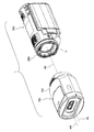
図1および図2に示すように、ビデオカメラユニット1(撮像装置の一例)は、ビデオカメラ200と、3Dアダプタ100(レンズユニットの一例)と、を備えている。
図2に示すように、3次元撮影を行う際、3Dアダプタ100はビデオカメラ200の先端299に装着される。ビデオカメラ200は光軸A0を有する1軸光学系Vを有している。一方、3Dアダプタ100は、左眼光軸ALおよび右眼光軸ARを有する2軸光学系を有している。ビデオカメラ200は2次元撮影にも3次元撮影にも対応している。2次元撮影を行う場合は、ビデオカメラ200のみで撮影を行い、3次元撮影を行う場合は、ビデオカメラ200に3Dアダプタ100を装着して撮影を行う。
なお、説明の便宜のため、ビデオカメラユニット1の被写体側を前側、ビデオカメラユニット1の被写体と反対側を後側、ビデオカメラユニット1の通常姿勢(以下、横撮り姿勢ともいう)における鉛直上側を上側、鉛直下側を下側ともいう。これらの表現はビデオカメラユニット1の使用状態を限定するものではない。
図1および図2に示すように、ビデオカメラユニット1(撮像装置の一例)は、ビデオカメラ200と、3Dアダプタ100(レンズユニットの一例)と、を備えている。
図2に示すように、3次元撮影を行う際、3Dアダプタ100はビデオカメラ200の先端299に装着される。ビデオカメラ200は光軸A0を有する1軸光学系Vを有している。一方、3Dアダプタ100は、左眼光軸ALおよび右眼光軸ARを有する2軸光学系を有している。ビデオカメラ200は2次元撮影にも3次元撮影にも対応している。2次元撮影を行う場合は、ビデオカメラ200のみで撮影を行い、3次元撮影を行う場合は、ビデオカメラ200に3Dアダプタ100を装着して撮影を行う。
なお、説明の便宜のため、ビデオカメラユニット1の被写体側を前側、ビデオカメラユニット1の被写体と反対側を後側、ビデオカメラユニット1の通常姿勢(以下、横撮り姿勢ともいう)における鉛直上側を上側、鉛直下側を下側ともいう。これらの表現はビデオカメラユニット1の使用状態を限定するものではない。
〔ビデオカメラ200の構成〕
図3に示すように、ビデオカメラ200は光学系VおよびCMOSイメージセンサ110を有している。
光学系V(本体光学系の一例)は、光軸A0を有する1軸光学系であり、第1レンズ群G1、第2レンズ群G2、第3レンズ群G3および第4レンズ群G4を有している。
第1レンズ群G1は光学系Vにおいて最も被写体に近い位置に配置されている。第2レンズ群G2はズーム調整用のレンズ群である。第3レンズ群G3は振れ補正用のレンズ群である。第4レンズ群G4はフォーカス調整用のレンズ群である。第2レンズ群G2はズームモータ(図示せず)により光軸A0に平行な方向に駆動する。これにより、光学系Vの焦点距離を調整することができる。
図3に示すように、ビデオカメラ200は光学系VおよびCMOSイメージセンサ110を有している。
光学系V(本体光学系の一例)は、光軸A0を有する1軸光学系であり、第1レンズ群G1、第2レンズ群G2、第3レンズ群G3および第4レンズ群G4を有している。
第1レンズ群G1は光学系Vにおいて最も被写体に近い位置に配置されている。第2レンズ群G2はズーム調整用のレンズ群である。第3レンズ群G3は振れ補正用のレンズ群である。第4レンズ群G4はフォーカス調整用のレンズ群である。第2レンズ群G2はズームモータ(図示せず)により光軸A0に平行な方向に駆動する。これにより、光学系Vの焦点距離を調整することができる。
CMOSイメージセンサ110(撮像素子の一例)は、光学系Vにより形成される被写体の光学像(以下、被写体像ともいう)を画像信号に変換する。CMOSイメージセンサ110で生成された画像信号は、画像処理部(図示せず)でデジタル化され画像データに変換される。CMOSイメージセンサ110により静止画データおよび動画データを取得できる。
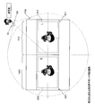
図4に示すように、CMOSイメージセンサ110は、光学系Vを透過した光を受ける受光面110a(図6参照)を有している。受光面110a上には被写体の光学像が形成される。受光面110aは第1受光面110Lおよび第2受光面110を有している。ビデオカメラ本体202の背面側から見た場合、第1受光面110Lは受光面110aの左半分、第2受光面110Rは受光面110aの右半分を占めている。第1受光面110Lおよび第2受光面110Rの面積は同じである。3Dアダプタ100をビデオカメラ200に装着して撮影を行う場合は、第1受光面110Lには左眼用光学像QL1が形成され、第2受光面110Rには右眼用光学像QR1が形成される。
図4に示すように、CMOSイメージセンサ110は、光学系Vを透過した光を受ける受光面110a(図6参照)を有している。受光面110a上には被写体の光学像が形成される。受光面110aは第1受光面110Lおよび第2受光面110を有している。ビデオカメラ本体202の背面側から見た場合、第1受光面110Lは受光面110aの左半分、第2受光面110Rは受光面110aの右半分を占めている。第1受光面110Lおよび第2受光面110Rの面積は同じである。3Dアダプタ100をビデオカメラ200に装着して撮影を行う場合は、第1受光面110Lには左眼用光学像QL1が形成され、第2受光面110Rには右眼用光学像QR1が形成される。
なお、CMOSイメージセンサ110は被写体の光学像を電気的な画像信号に変換する撮像素子の一例である。撮像素子は、CMOSイメージセンサ110やCCDイメージセンサ等の光電変換素子を含む概念である。
3次元撮影の場合、画像処理部はCMOSイメージセンサ110で生成された画像信号から左眼用画像データおよび右眼用画像データを抽出する。左眼用画像データは左眼用光学系OLにより形成される左眼用光学像QL1の一部に対応している。右眼用画像データは右眼用光学系ORにより形成される右眼用光学像QR1の一部に対応している。予め設定された第1抽出領域AL2および第2抽出領域AR2に基づいて、画像処理部は左眼用画像データおよび右眼用画像データを抽出する。抽出された左眼用画像データおよび右眼用画像データはDRAM(図示せず)に一時的に格納され、補正処理および圧縮処理が左眼用画像データおよび右眼用画像データに対して施される。
3次元撮影の場合、画像処理部はCMOSイメージセンサ110で生成された画像信号から左眼用画像データおよび右眼用画像データを抽出する。左眼用画像データは左眼用光学系OLにより形成される左眼用光学像QL1の一部に対応している。右眼用画像データは右眼用光学系ORにより形成される右眼用光学像QR1の一部に対応している。予め設定された第1抽出領域AL2および第2抽出領域AR2に基づいて、画像処理部は左眼用画像データおよび右眼用画像データを抽出する。抽出された左眼用画像データおよび右眼用画像データはDRAM(図示せず)に一時的に格納され、補正処理および圧縮処理が左眼用画像データおよび右眼用画像データに対して施される。
一方、画像処理部は、ステレオベースおよび輻輳角を含むメタデータを生成する。メタデータ生成後、圧縮された左眼用および右眼用画像データとメタデータとを組み合わせて、MPF形式の画像ファイルが画像処理部により生成される。生成された画像ファイルは、例えばメモリーカードなどの記録媒体に記録される。
〔3Dアダプタ100の構成〕
図2に示すように、3Dアダプタ100は、ビデオカメラ200により3次元撮影を行うためのコンバージョンレンズであり、ビデオカメラ200の先端299に装着可能となっている。3Dアダプタ100には、左右1対の光学系により1つの撮像素子上に2つの光学像が形成される並置撮影方式(サイド・バイ・サイド方式ともいう)が採用されている。3Dアダプタ100をビデオカメラ200に装着することで、1軸光学系Vを、3次元撮影が可能な2軸光学系に切り替えることができる。
〔3Dアダプタ100の構成〕
図2に示すように、3Dアダプタ100は、ビデオカメラ200により3次元撮影を行うためのコンバージョンレンズであり、ビデオカメラ200の先端299に装着可能となっている。3Dアダプタ100には、左右1対の光学系により1つの撮像素子上に2つの光学像が形成される並置撮影方式(サイド・バイ・サイド方式ともいう)が採用されている。3Dアダプタ100をビデオカメラ200に装着することで、1軸光学系Vを、3次元撮影が可能な2軸光学系に切り替えることができる。
3Dアダプタ100は、外装部101、左眼用光学系OLおよび右眼用光学系ORを有している。左眼用光学系OLおよび右眼用光学系ORは外装部101内に収容されている。
ここで、左眼用光学系とは、左側の視点に対応した光学系であり、具体的には、最も被写体側(前側)に配置されている光学素子が被写体に向かって左側に配置されている光学系をいう。同様に、右眼用光学系とは、右側の視点に対応した光学系であり、具体的には、最も被写体側(前側)に配置されている光学素子が被写体に向かって右側に配置されている光学系をいう。
なお、ここでいう光学素子は、正または負の屈折力を持った光学素子をいい、例えば、正や負の屈折力を持たない、単なる防塵用のガラスは含まない。
ここで、左眼用光学系とは、左側の視点に対応した光学系であり、具体的には、最も被写体側(前側)に配置されている光学素子が被写体に向かって左側に配置されている光学系をいう。同様に、右眼用光学系とは、右側の視点に対応した光学系であり、具体的には、最も被写体側(前側)に配置されている光学素子が被写体に向かって右側に配置されている光学系をいう。
なお、ここでいう光学素子は、正または負の屈折力を持った光学素子をいい、例えば、正や負の屈折力を持たない、単なる防塵用のガラスは含まない。
図3に示すように、左眼用光学系OLは、左側視点(第1の視点または第2の視点の一例)から見た左眼用光学像(第1光学像または第2光学像の一例)を形成するための光学系であり、左眼負レンズ群G1L、左眼正レンズ群G2Lおよび左眼プリズム群G3Lを有している。左眼用光学系OLは略アフォーカル光学系である。
左眼負レンズ群G1Lは、全体として負の焦点距離(負の屈折力ともいう)を有しており、第1レンズL1L、第2レンズL2L、第3レンズL3Lおよび第4レンズL4Lを有している。左眼負レンズ群G1Lは左眼用光学系OLにおいて最も被写体側に(被写体に最も近い位置に)配置されている。第1レンズL1Lは負の焦点距離を持っている。第2レンズL2Lは負の焦点距離を持っている。第3レンズL3Lは正の焦点距離(正の屈折力ともいう)を持っている。第4レンズL4Lは、負の焦点距離を持っており、第3レンズL3Lに接合されている。左眼負レンズ群G1Lの合成焦点距離は負となっている。
左眼負レンズ群G1Lは、全体として負の焦点距離(負の屈折力ともいう)を有しており、第1レンズL1L、第2レンズL2L、第3レンズL3Lおよび第4レンズL4Lを有している。左眼負レンズ群G1Lは左眼用光学系OLにおいて最も被写体側に(被写体に最も近い位置に)配置されている。第1レンズL1Lは負の焦点距離を持っている。第2レンズL2Lは負の焦点距離を持っている。第3レンズL3Lは正の焦点距離(正の屈折力ともいう)を持っている。第4レンズL4Lは、負の焦点距離を持っており、第3レンズL3Lに接合されている。左眼負レンズ群G1Lの合成焦点距離は負となっている。
左眼正レンズ群G2Lは、左眼負レンズ群G1Lの透過光を受けるレンズ群であり、左眼負レンズ群G1Lの被写体と反対側に配置されている。左眼正レンズ群G2Lは左眼負レンズ群G1Lと左眼プリズム群G3Lとの間に配置されている。
左眼正レンズ群G2Lは、第5レンズL5L、第6レンズL6Lおよび第7レンズL7Lを有している。第5レンズL5Lは正の焦点距離を持っている。第6レンズL6Lは正の焦点距離を持っている。第7レンズL7Lは、負の焦点距離を持っており、第6レンズL6Lに接合されている。
左眼負レンズ群G1Lの透過光は発散するので、左眼正レンズ群G2Lの入射面の光学的有効領域は左眼負レンズ群G1Lの出射面の光学的有効領域よりも広い。このため、左眼正レンズ群G2Lの有効径は左眼負レンズ群G1Lの有効径よりも大きくなっている。また、左眼光軸ALおよび右眼光軸ARを近づけるために、左眼正レンズ群G2Lは概ね半円形状を有している。具体的には、左眼正レンズ群G2Lの内側は真っ直ぐカットされている。これにより、左眼正レンズ群G2Lと右眼正レンズ群G2Rとを近づけて配置することができ、ステレオベース(図3および図5参照)を小さくすることができる。また、これに伴い、左眼光軸ALおよび右眼光軸ARにより形成される輻輳角(図5参照)を適正な値に設定しやすくなる。
左眼正レンズ群G2Lは、第5レンズL5L、第6レンズL6Lおよび第7レンズL7Lを有している。第5レンズL5Lは正の焦点距離を持っている。第6レンズL6Lは正の焦点距離を持っている。第7レンズL7Lは、負の焦点距離を持っており、第6レンズL6Lに接合されている。
左眼負レンズ群G1Lの透過光は発散するので、左眼正レンズ群G2Lの入射面の光学的有効領域は左眼負レンズ群G1Lの出射面の光学的有効領域よりも広い。このため、左眼正レンズ群G2Lの有効径は左眼負レンズ群G1Lの有効径よりも大きくなっている。また、左眼光軸ALおよび右眼光軸ARを近づけるために、左眼正レンズ群G2Lは概ね半円形状を有している。具体的には、左眼正レンズ群G2Lの内側は真っ直ぐカットされている。これにより、左眼正レンズ群G2Lと右眼正レンズ群G2Rとを近づけて配置することができ、ステレオベース(図3および図5参照)を小さくすることができる。また、これに伴い、左眼光軸ALおよび右眼光軸ARにより形成される輻輳角(図5参照)を適正な値に設定しやすくなる。
ここで、左眼光軸ALは左眼負レンズ群G1Lおよび左眼正レンズ群G2Lにより定義される。具体的には、左眼光軸ALは左眼負レンズ群G1Lの主点と左眼正レンズ群G2Lの主点とを通るラインで定義される。左眼光軸ALおよび右眼光軸ARは被写体側からCMOSイメージセンサ110側へいくにしたがって互いに離れるように配置されている。
左眼プリズム群G3Lは、左眼正レンズ群G2Lの透過光を受けるレンズ群であり、第1前側プリズムP1Lおよび第1後側プリズムP2Lを有している。第1前側プリズムP1Lおよび第1後側プリズムP2Lは屈折方式のウェッジプリズムである。左眼プリズム群G3Lは、ビデオカメラ200の光学系V(1軸光学系)に左眼正レンズ群G2Lの透過光が導入されるように左眼正レンズ群G2Lの透過光を屈折させる。具体的には、左眼プリズム群G3Lにより左眼正レンズ群G2Lの透過光は内側へ屈折される。第1前側プリズムP1Lは左眼正レンズ群G2Lの透過光を内側へ屈折させる。第1後側プリズムP2Lは第1前側プリズムP1Lの透過光を外側へ屈折させる。第1前側プリズムP1Lは主に、左眼正レンズ群G2Lの透過光を内側へ屈折させる機能を有しており、第1後側プリズムP2Lは主に、屈折による色分散を補正する機能を有している。
左眼プリズム群G3Lは、左眼正レンズ群G2Lの透過光を受けるレンズ群であり、第1前側プリズムP1Lおよび第1後側プリズムP2Lを有している。第1前側プリズムP1Lおよび第1後側プリズムP2Lは屈折方式のウェッジプリズムである。左眼プリズム群G3Lは、ビデオカメラ200の光学系V(1軸光学系)に左眼正レンズ群G2Lの透過光が導入されるように左眼正レンズ群G2Lの透過光を屈折させる。具体的には、左眼プリズム群G3Lにより左眼正レンズ群G2Lの透過光は内側へ屈折される。第1前側プリズムP1Lは左眼正レンズ群G2Lの透過光を内側へ屈折させる。第1後側プリズムP2Lは第1前側プリズムP1Lの透過光を外側へ屈折させる。第1前側プリズムP1Lは主に、左眼正レンズ群G2Lの透過光を内側へ屈折させる機能を有しており、第1後側プリズムP2Lは主に、屈折による色分散を補正する機能を有している。
図3に示すように、右眼用光学系ORは、右側視点から見た右眼用光学像を形成するための光学系であり、右眼負レンズ群G1R、右眼正レンズ群G2Rおよび右眼プリズム群G3Rを有している。右眼用光学系ORは略アフォーカル光学系である。
右眼負レンズ群G1Rは、全体として負の焦点距離(負の屈折力ともいう)を有しており、第2レンズR1R、第2レンズR2R、第3レンズR3Rおよび第4レンズR4Rを有している。右眼負レンズ群G1Rは右眼用光学系ORにおいて最も被写体側に(被写体に最も近い位置に)配置されている。第2レンズR1Rは負の焦点距離を持っている。第2レンズR2Rは負の焦点距離を持っている。第3レンズR3Rは正の焦点距離(正の屈折力ともいう)を持っている。第4レンズR4Rは、負の焦点距離を持っており、第3レンズR3Rに接合されている。右眼負レンズ群G1Rの合成焦点距離は負となっている。
右眼負レンズ群G1Rは、全体として負の焦点距離(負の屈折力ともいう)を有しており、第2レンズR1R、第2レンズR2R、第3レンズR3Rおよび第4レンズR4Rを有している。右眼負レンズ群G1Rは右眼用光学系ORにおいて最も被写体側に(被写体に最も近い位置に)配置されている。第2レンズR1Rは負の焦点距離を持っている。第2レンズR2Rは負の焦点距離を持っている。第3レンズR3Rは正の焦点距離(正の屈折力ともいう)を持っている。第4レンズR4Rは、負の焦点距離を持っており、第3レンズR3Rに接合されている。右眼負レンズ群G1Rの合成焦点距離は負となっている。
右眼正レンズ群G2Rは、右眼負レンズ群G1Rの透過光を受けるレンズ群であり、右眼負レンズ群G1Rの被写体と反対側に配置されている。右眼正レンズ群G2Rは右眼負レンズ群G1Rと右眼プリズム群G3Rとの間に配置されている。
右眼正レンズ群G2Rは、第5レンズR5R、第6レンズR6Rおよび第7レンズR7Rを有している。第5レンズR5Rは正の焦点距離を持っている。第6レンズR6Rは正の焦点距離を持っている。第7レンズR7Rは、負の焦点距離を持っており、第6レンズR6Rに接合されている。
右眼負レンズ群G1Rの透過光は発散するので、右眼正レンズ群G2Rの入射面の光学的有効領域は右眼負レンズ群G1Rの出射面の光学的有効領域よりも広い。このため、右眼正レンズ群G2Rの有効径は右眼負レンズ群G1Rの有効径よりも大きくなっている。また、右眼光軸ARおよび右眼光軸ARを近づけるために、右眼正レンズ群G2Rは概ね半円形状を有している。具体的には、右眼正レンズ群G2Rの内側は真っ直ぐカットされている。これにより、ステレオベース(図3および図5参照)を小さくすることができ、右眼光軸ARおよび右眼光軸ARにより形成される輻輳角(図5参照)を小さくすることができる。
右眼正レンズ群G2Rは、第5レンズR5R、第6レンズR6Rおよび第7レンズR7Rを有している。第5レンズR5Rは正の焦点距離を持っている。第6レンズR6Rは正の焦点距離を持っている。第7レンズR7Rは、負の焦点距離を持っており、第6レンズR6Rに接合されている。
右眼負レンズ群G1Rの透過光は発散するので、右眼正レンズ群G2Rの入射面の光学的有効領域は右眼負レンズ群G1Rの出射面の光学的有効領域よりも広い。このため、右眼正レンズ群G2Rの有効径は右眼負レンズ群G1Rの有効径よりも大きくなっている。また、右眼光軸ARおよび右眼光軸ARを近づけるために、右眼正レンズ群G2Rは概ね半円形状を有している。具体的には、右眼正レンズ群G2Rの内側は真っ直ぐカットされている。これにより、ステレオベース(図3および図5参照)を小さくすることができ、右眼光軸ARおよび右眼光軸ARにより形成される輻輳角(図5参照)を小さくすることができる。
ここで、右眼光軸ARは右眼負レンズ群G1Rおよび右眼正レンズ群G2Rにより定義される。具体的には、右眼光軸ARは右眼負レンズ群G1Rの主点と右眼正レンズ群G2Rの主点とを通るラインで定義される。左眼光軸ALおよび右眼光軸ARは被写体側からCMOSイメージセンサ110側へいくにしたがって互いに離れるように配置されている。
右眼プリズム群G3Rは、右眼正レンズ群G2Rの透過光を受けるレンズ群であり、第2前側プリズムP1Rおよび第2後側プリズムP2Rを有している。第2前側プリズムP1Rおよび第2後側プリズムP2Rは屈折方式のウェッジプリズムである。右眼プリズム群G3Rは、ビデオカメラ200の光学系V(1軸光学系)に右眼正レンズ群G2Rの透過光が導入されるように右眼正レンズ群G2Rの透過光を屈折させる。具体的には、右眼プリズム群G3Rにより右眼正レンズ群G2Rの透過光は内側へ屈折される。第2前側プリズムP1Rは右眼正レンズ群G2Rの透過光を内側へ屈折させる。第2後側プリズムP2Rは第2前側プリズムP1Rの透過光を外側へ屈折させる。第2前側プリズムP1Rは主に、右眼正レンズ群G2Rの透過光を内側へ屈折させる機能を有しており、第2後側プリズムP2Rは主に、屈折による色分散を補正する機能を有している。
右眼プリズム群G3Rは、右眼正レンズ群G2Rの透過光を受けるレンズ群であり、第2前側プリズムP1Rおよび第2後側プリズムP2Rを有している。第2前側プリズムP1Rおよび第2後側プリズムP2Rは屈折方式のウェッジプリズムである。右眼プリズム群G3Rは、ビデオカメラ200の光学系V(1軸光学系)に右眼正レンズ群G2Rの透過光が導入されるように右眼正レンズ群G2Rの透過光を屈折させる。具体的には、右眼プリズム群G3Rにより右眼正レンズ群G2Rの透過光は内側へ屈折される。第2前側プリズムP1Rは右眼正レンズ群G2Rの透過光を内側へ屈折させる。第2後側プリズムP2Rは第2前側プリズムP1Rの透過光を外側へ屈折させる。第2前側プリズムP1Rは主に、右眼正レンズ群G2Rの透過光を内側へ屈折させる機能を有しており、第2後側プリズムP2Rは主に、屈折による色分散を補正する機能を有している。
〔焦点距離およびステレオベースの決定方法について〕
ここで、3Dアダプタ100の焦点距離およびステレオベースの決定方法について説明する。
3次元光学系(左眼用光学系OLおよび右眼用光学系OR)の設計を行う場合、焦点距離およびステレオベースを決定する必要がある。図3および図5に示すように、ステレオベースとは2つの光軸(左眼光軸ALおよび右眼光軸AR)の間の距離をいう。
例えば、左眼用光学系OLおよび右眼用光学系ORの場合、ステレオベースSBは、左眼光軸ALおよび右眼光軸ARが最も離れた位置での左眼光軸ALおよび右眼光軸ARの間の距離をいう。本実施形態では、図3に示すように、左眼プリズム群G3Lの入射面および右眼プリズム群G3Rの入射面を基準としてステレオベースSBが定義されている。
ここで、3Dアダプタ100の焦点距離およびステレオベースの決定方法について説明する。
3次元光学系(左眼用光学系OLおよび右眼用光学系OR)の設計を行う場合、焦点距離およびステレオベースを決定する必要がある。図3および図5に示すように、ステレオベースとは2つの光軸(左眼光軸ALおよび右眼光軸AR)の間の距離をいう。
例えば、左眼用光学系OLおよび右眼用光学系ORの場合、ステレオベースSBは、左眼光軸ALおよび右眼光軸ARが最も離れた位置での左眼光軸ALおよび右眼光軸ARの間の距離をいう。本実施形態では、図3に示すように、左眼プリズム群G3Lの入射面および右眼プリズム群G3Rの入射面を基準としてステレオベースSBが定義されている。
ステレオ画像で再現される立体感は焦点距離およびステレオベースによって異なってくるので、3次元光学系の設計上、焦点距離およびステレオベースは非常に重要となる。
しかし、実際には、焦点距離およびステレオベースをそれぞれ適正と思われる値に別々に設定していることが多いが、焦点距離およびステレオベースを別々に設定すると、両者のバランスをとるのが難しい。
例えば、人間(より詳細には、成人)が視聴するためのステレオ画像を撮影する3次元光学系を設計する際、一般的には、3次元光学系のステレオベースSBは人間の両目の間の距離と一致させることが好ましいと考えられている。
しかし、3次元光学系のステレオベースSBを単に人間の両目の間の距離と一致させるだけでは、焦点距離fによっては、快適な立体視をできる撮影距離の範囲がごく一部の範囲に限定されてしまう。この結果、その他の撮影距離では、例えば、スクリーンの手前に再現される像がスクリーンから飛び出しすぎたり、あるいは、スクリーンよりも奥に再現される像がスクリーンから異常に遠くに見えたりする。撮影距離とは、撮影する際の撮像装置から主被写体までの距離をいい、立体視の場合には視聴者からスクリーンまでの距離に相当する。
しかし、実際には、焦点距離およびステレオベースをそれぞれ適正と思われる値に別々に設定していることが多いが、焦点距離およびステレオベースを別々に設定すると、両者のバランスをとるのが難しい。
例えば、人間(より詳細には、成人)が視聴するためのステレオ画像を撮影する3次元光学系を設計する際、一般的には、3次元光学系のステレオベースSBは人間の両目の間の距離と一致させることが好ましいと考えられている。
しかし、3次元光学系のステレオベースSBを単に人間の両目の間の距離と一致させるだけでは、焦点距離fによっては、快適な立体視をできる撮影距離の範囲がごく一部の範囲に限定されてしまう。この結果、その他の撮影距離では、例えば、スクリーンの手前に再現される像がスクリーンから飛び出しすぎたり、あるいは、スクリーンよりも奥に再現される像がスクリーンから異常に遠くに見えたりする。撮影距離とは、撮影する際の撮像装置から主被写体までの距離をいい、立体視の場合には視聴者からスクリーンまでの距離に相当する。
したがって、製品の試作を重ねて最終的に焦点距離およびステレオベースを決定しているのが実状である。
しかし、製品の試作を重ねると設計費用が増大してしまい、製造コストの増大を招くので、3次元光学系の設計が容易となる設計手法が求められている。
そこで、本実施形態に係る3Dアダプタ100では、新たに35mm換算のステレオベースを定義している。
具体的には、左眼用光学系OLと光学系Vとで定まる、または、右眼用光学系ORと光学系Vとで定まる、焦点距離をf、焦点距離fの35mm換算の焦点距離をf35、左眼用光学系OLおよび右眼用光学系ORのステレオベースをSB、左眼用光学系OLおよび右眼用光学系ORの35mm換算のステレオベースをSB35とした場合に、換算ステレオベースSB35を以下の式(1)で定義する。
しかし、製品の試作を重ねると設計費用が増大してしまい、製造コストの増大を招くので、3次元光学系の設計が容易となる設計手法が求められている。
そこで、本実施形態に係る3Dアダプタ100では、新たに35mm換算のステレオベースを定義している。
具体的には、左眼用光学系OLと光学系Vとで定まる、または、右眼用光学系ORと光学系Vとで定まる、焦点距離をf、焦点距離fの35mm換算の焦点距離をf35、左眼用光学系OLおよび右眼用光学系ORのステレオベースをSB、左眼用光学系OLおよび右眼用光学系ORの35mm換算のステレオベースをSB35とした場合に、換算ステレオベースSB35を以下の式(1)で定義する。
SB35=SB×f35/f ・・・(1)
この換算ステレオベースSB35は、ステレオ画像により再現される立体感の指標であり、焦点距離fおよびステレオベースSBのバランスをとるための基準値と言うこともできる。換算ステレオベースSB35の導入により、ステレオ画像で再現される立体感をある一定の基準で管理することができる。例えば、換算ステレオベースSB35を決めておけば、ステレオ画像で再現される立体感をある一定の範囲内に収めつつ、式(1)を用いて焦点距離fおよびステレオベースSBを簡単に求めることができる。
ここで、一例として、人間(より詳細には、成人)が視聴するためのステレオ画像を撮影する場合の焦点距離fおよびステレオベースSBの算出方法について説明する。
(A)条件設定
まず、人間の眼球の構成を基準として、人間の視差に適した焦点距離f´、換算焦点距離f35´および両目の間隔SB´を決定する。
この換算ステレオベースSB35は、ステレオ画像により再現される立体感の指標であり、焦点距離fおよびステレオベースSBのバランスをとるための基準値と言うこともできる。換算ステレオベースSB35の導入により、ステレオ画像で再現される立体感をある一定の基準で管理することができる。例えば、換算ステレオベースSB35を決めておけば、ステレオ画像で再現される立体感をある一定の範囲内に収めつつ、式(1)を用いて焦点距離fおよびステレオベースSBを簡単に求めることができる。
ここで、一例として、人間(より詳細には、成人)が視聴するためのステレオ画像を撮影する場合の焦点距離fおよびステレオベースSBの算出方法について説明する。
(A)条件設定
まず、人間の眼球の構成を基準として、人間の視差に適した焦点距離f´、換算焦点距離f35´および両目の間隔SB´を決定する。
例えば、人間の視野の範囲を基準とすると、人間の眼球の35mm換算の焦点距離f35´は、以下の式(2)を満たすのが好ましい。
35mm≦f35´≦85mm ・・・(2)
また、人間(より詳細には、成人)が平常時に無限遠を見ているときの眼球の焦点距離f´は、以下の式(3)を満たすのが一般的である。
16mm≦f´≦18mm ・・・(3)
さらに、人間の右眼および左眼の間隔SB´は、以下の式(4)を満たすのが一般的である。
55mm≦SB´≦75mm ・・・(4)
上記の式(2)~(4)を満たすように条件を設定することで、人間にとって自然な視差をカバーすることができ、快適な立体視が可能なステレオ画像を取得しやすくなる。言い換えると、適正なステレオ画像を取得するためには、上記の条件に適合する範囲で左眼用光学系OLおよび右眼用光学系ORのステレオベースSBおよび焦点距離fを決定する必要がある。
35mm≦f35´≦85mm ・・・(2)
また、人間(より詳細には、成人)が平常時に無限遠を見ているときの眼球の焦点距離f´は、以下の式(3)を満たすのが一般的である。
16mm≦f´≦18mm ・・・(3)
さらに、人間の右眼および左眼の間隔SB´は、以下の式(4)を満たすのが一般的である。
55mm≦SB´≦75mm ・・・(4)
上記の式(2)~(4)を満たすように条件を設定することで、人間にとって自然な視差をカバーすることができ、快適な立体視が可能なステレオ画像を取得しやすくなる。言い換えると、適正なステレオ画像を取得するためには、上記の条件に適合する範囲で左眼用光学系OLおよび右眼用光学系ORのステレオベースSBおよび焦点距離fを決定する必要がある。
(B)換算ステレオベースSB35の算出
そこで、上記の式(1)~(4)をもとに、人間の視差に適した換算ステレオベースSB35の範囲を算出する。式(1)の焦点距離f、換算焦点距離f35およびステレオベースSBに、式(2)~(4)の焦点距離f´、換算焦点距離f35´およびステレオベースSB´を代入すると、換算ステレオベースSB35の最大値および最小値は、以下のようになる。
f35=f35´=85mm、f=f´=16mm、SB=SB´=75mmのとき、SB35=398.4mm≒400mmとなる。
また、f35=f35´=35mm、f=f´=18mm、SB=SB´=55mmのとき、SB35=107mmとなる。
そこで、上記の式(1)~(4)をもとに、人間の視差に適した換算ステレオベースSB35の範囲を算出する。式(1)の焦点距離f、換算焦点距離f35およびステレオベースSBに、式(2)~(4)の焦点距離f´、換算焦点距離f35´およびステレオベースSB´を代入すると、換算ステレオベースSB35の最大値および最小値は、以下のようになる。
f35=f35´=85mm、f=f´=16mm、SB=SB´=75mmのとき、SB35=398.4mm≒400mmとなる。
また、f35=f35´=35mm、f=f´=18mm、SB=SB´=55mmのとき、SB35=107mmとなる。
したがって、人間の視差に適した換算ステレオベースSB35は、以下に示す式(5)を満たすことになる。
107mm≦SB35≦400mm ・・・(5)
また、より適正なステレオ画像を取得したい場合は、以下の式(6)を満たすことが好ましい。
150mm≦SB35≦350mm ・・・(6)
さらに、より適正なステレオ画像を取得したい場合は、以下の式(7)を満たすことが好ましい。
200mm≦SB35≦300mm ・・・(7)
(C)焦点距離fおよびステレオベースSBの算出
実際に3次元光学系の設計を行う場合には、例えば式(1)および(5)に基づいて最適なステレオベースSBおよび焦点距離fを決定することで、人間にとって自然な視差を有するステレオ画像を取得できる3次元光学系の仕様を簡単に決定することができる。
107mm≦SB35≦400mm ・・・(5)
また、より適正なステレオ画像を取得したい場合は、以下の式(6)を満たすことが好ましい。
150mm≦SB35≦350mm ・・・(6)
さらに、より適正なステレオ画像を取得したい場合は、以下の式(7)を満たすことが好ましい。
200mm≦SB35≦300mm ・・・(7)
(C)焦点距離fおよびステレオベースSBの算出
実際に3次元光学系の設計を行う場合には、例えば式(1)および(5)に基づいて最適なステレオベースSBおよび焦点距離fを決定することで、人間にとって自然な視差を有するステレオ画像を取得できる3次元光学系の仕様を簡単に決定することができる。
具体的には、式(5)に示す範囲内で換算ステレオベースSB35を設定する。例えば、換算ステレオベースSB35が短いと、ステレオ画像で再現される立体感がより強調され、換算ステレオベースSB35が長いと、ステレオ画像で再現される立体感が抑制される。
ここで、換算焦点距離f35は焦点距離fおよびCMOSイメージセンサ110の仕様に基づいて決まるので、焦点距離fおよびステレオベースSBのうち一方を決定すると、もう一方の値を換算ステレオベースSB35および式(1)に基づいて算出することができる。
例えば、焦点距離fは3次元撮影を行う光学系全体の仕様により決まってしまうことが多いので、焦点距離fが決まっていると仮定すると、35mm換算の焦点距離f35は焦点距離fおよびCMOSイメージセンサ110の仕様に基づいて決まる。
ここで、換算焦点距離f35は焦点距離fおよびCMOSイメージセンサ110の仕様に基づいて決まるので、焦点距離fおよびステレオベースSBのうち一方を決定すると、もう一方の値を換算ステレオベースSB35および式(1)に基づいて算出することができる。
例えば、焦点距離fは3次元撮影を行う光学系全体の仕様により決まってしまうことが多いので、焦点距離fが決まっていると仮定すると、35mm換算の焦点距離f35は焦点距離fおよびCMOSイメージセンサ110の仕様に基づいて決まる。
したがって、焦点距離f、換算焦点距離f35、換算ステレオベースSB35を式(1)に代入すると、ある特定の焦点距離fと相性のよいステレオベースSBを算出することができる。
なお、ステレオベースSBが製品の仕様上、決まっている場合でも、CMOSイメージセンサ110の仕様、換算ステレオベースSB35、ステレオベースSBおよび式(1)に基づいて、焦点距離fを求めることができる。
(D)焦点距離fおよびステレオベースSBの算出方法のまとめ
以上に説明した焦点距離fおよびステレオベースSBの算出方法をまとめると図6に示す表のようになる。
図6に示すように、まず、人間の眼球の構成を基準として焦点距離f´、換算焦点距離f35´およびステレオベースSB´を前述のように決定する。
なお、ステレオベースSBが製品の仕様上、決まっている場合でも、CMOSイメージセンサ110の仕様、換算ステレオベースSB35、ステレオベースSBおよび式(1)に基づいて、焦点距離fを求めることができる。
(D)焦点距離fおよびステレオベースSBの算出方法のまとめ
以上に説明した焦点距離fおよびステレオベースSBの算出方法をまとめると図6に示す表のようになる。
図6に示すように、まず、人間の眼球の構成を基準として焦点距離f´、換算焦点距離f35´およびステレオベースSB´を前述のように決定する。
次に、各数値および式(1)を用いて、人間の視差に適した換算ステレオベースSB35の範囲を算出し、算出した範囲から、人間の視差に適した換算ステレオベースSB35を設定する。
さらに、設定した換算ステレオベースSB35および式(1)に基づいて、焦点距離fおよびステレオベースSBを算出する。前述の例では、焦点距離f、換算焦点距離f35および換算ステレオベースSB35を式(1)に代入して、ステレオベースSBを算出している。
このように、換算ステレオベースSB35を使って焦点距離fおよびステレオベースSBを決定することで、適正なステレオ画像を取得する上で相性のよい焦点距離fおよびステレオベースSBを簡単に決定することができる。
さらに、設定した換算ステレオベースSB35および式(1)に基づいて、焦点距離fおよびステレオベースSBを算出する。前述の例では、焦点距離f、換算焦点距離f35および換算ステレオベースSB35を式(1)に代入して、ステレオベースSBを算出している。
このように、換算ステレオベースSB35を使って焦点距離fおよびステレオベースSBを決定することで、適正なステレオ画像を取得する上で相性のよい焦点距離fおよびステレオベースSBを簡単に決定することができる。
逆に言えば、換算ステレオベースSB35および式(1)を用いると、レンズユニットが換算ステレオベースSB35を定義して設計されているか否かを判断することができる。例えば、あるレンズユニットの3次元光学系が、人間の視差に適した換算ステレオベースSB35を定義して設計されているかを調べたい場合は、その3次元光学系を調べて焦点距離fおよびステレオベースSBを特定する。35mm換算の焦点距離f35も、カメラ本体側の撮像素子や光学系の仕様に基づいて特定することができる。したがって、そのレンズユニットの焦点距離f、35mm換算の焦点距離f35およびステレオベースSBを式(1)に代入して換算ステレオベースSB35を算出し、換算ステレオベースSB35が式(5)の条件を満たしているか否かを判定することで、換算ステレオベースSB35を定義して焦点距離fやステレオベースSBを決定しているか否かを判断することができる。
〔3Dアダプタの特徴〕
以上に説明したように、3Dアダプタ100では、ステレオ画像で再現される立体感の指標となる換算ステレオベースSB35を式(1)で定義し、換算ステレオベースSB35が人間の視差に適した範囲に設定されているので、人間の視差に適した範囲内で、焦点距離fおよびステレオベースSBのバランスをとりやすくなる。したがって、焦点距離fおよびステレオベースSBを簡単に決定することができ、製造コストの低減が可能となる。さらに、人間の視差に適した範囲に換算ステレオベースSB35が設定されているので、人間の視差に適したステレオ画像を取得することができる。
したがって、上記の技術であれば、製造コストを低減しつつ適正なステレオ画像を取得できるレンズユニットおよび撮像装置を提供することができる。
以上に説明したように、3Dアダプタ100では、ステレオ画像で再現される立体感の指標となる換算ステレオベースSB35を式(1)で定義し、換算ステレオベースSB35が人間の視差に適した範囲に設定されているので、人間の視差に適した範囲内で、焦点距離fおよびステレオベースSBのバランスをとりやすくなる。したがって、焦点距離fおよびステレオベースSBを簡単に決定することができ、製造コストの低減が可能となる。さらに、人間の視差に適した範囲に換算ステレオベースSB35が設定されているので、人間の視差に適したステレオ画像を取得することができる。
したがって、上記の技術であれば、製造コストを低減しつつ適正なステレオ画像を取得できるレンズユニットおよび撮像装置を提供することができる。
また、換算ステレオベースSB35がSB35≦400mmを満たすので、より適正なステレオ画像を取得することができ、3Dアダプタ100の品質をより安定化することができる。
なお、SB35≦350mm、SB35≦300mmおよび107mm≦SB35についても同様に、より適正なステレオ画像を取得することができ、3Dアダプタ100の品質をさらに安定化することができる。
〔他の実施形態〕
本発明は、前述の実施形態に限定されるものではなく、本発明の範囲を逸脱することなく種々の変形および修正が可能である。
(A)撮像装置は動画だけでなく静止画撮影が可能な装置であってもよい。例えば、レンズユニットは、3Dアダプタ100に限定されず、例えば1眼カメラに用いられる交換レンズユニットであってもよい。さらに、レンズユニットは脱着式でなく撮像装置に内蔵されていてもよい。
なお、SB35≦350mm、SB35≦300mmおよび107mm≦SB35についても同様に、より適正なステレオ画像を取得することができ、3Dアダプタ100の品質をさらに安定化することができる。
〔他の実施形態〕
本発明は、前述の実施形態に限定されるものではなく、本発明の範囲を逸脱することなく種々の変形および修正が可能である。
(A)撮像装置は動画だけでなく静止画撮影が可能な装置であってもよい。例えば、レンズユニットは、3Dアダプタ100に限定されず、例えば1眼カメラに用いられる交換レンズユニットであってもよい。さらに、レンズユニットは脱着式でなく撮像装置に内蔵されていてもよい。
(B)換算ステレオベースSB35を用いて、焦点距離fおよびステレオベースSBを算出する場合の他に、焦点距離fのみを算出する場合、あるいは、ステレオベースSBを算出する場合にも、換算ステレオベースSB35および式(1)を利用することができる。
さらに、換算ステレオベースSB35を用いた計算式は前述の式(1)に限定されない。換算ステレオベースSB35に基づいて焦点距離fおよびステレオベースSBのうち少なくとも一方を決定しているのであれば、適正なステレオ画像を取得できる範囲内で式(1)が変更されてもよい。
さらに、換算ステレオベースSB35を用いた計算式は前述の式(1)に限定されない。換算ステレオベースSB35に基づいて焦点距離fおよびステレオベースSBのうち少なくとも一方を決定しているのであれば、適正なステレオ画像を取得できる範囲内で式(1)が変更されてもよい。
ここに開示されるレンズユニットであれば、製造コストを低減しつつ適正なステレオ画像を取得できる。したがって、上記の技術は、レンズユニットおよび撮像装置に適用可能である。
1 ビデオカメラユニット(撮像装置の一例)
100 3Dアダプタ(レンズユニットの一例)
110 CMOSイメージセンサ(撮像素子の一例)
V 光学系(本体光学系の一例)
OL 左眼用光学系(第1光学系または第2光学系の一例)
OR 右眼用光学系(第1光学系または第2光学系の一例)
f 焦点距離
f35 35mm換算の焦点距離
SB ステレオベース
SB35 換算ステレオベース
100 3Dアダプタ(レンズユニットの一例)
110 CMOSイメージセンサ(撮像素子の一例)
V 光学系(本体光学系の一例)
OL 左眼用光学系(第1光学系または第2光学系の一例)
OR 右眼用光学系(第1光学系または第2光学系の一例)
f 焦点距離
f35 35mm換算の焦点距離
SB ステレオベース
SB35 換算ステレオベース
Claims (9)
- 第1光学像および第2光学像を本体光学系を介して撮像素子上に形成するためのレンズユニットであって、
第1の視点から見た前記第1光学像を形成するための第1光学系と、
前記第1の視点とは異なる第2の視点から見た前記第2光学像を形成するための第2光学系と、を備え、
前記第1光学系と前記本体光学系とで定まる、または、前記第2光学系と前記本体光学系とで定まる、焦点距離をf、
前記焦点距離の35mm換算の焦点距離をf35、
前記第1および第2光学系のステレオベースをSB、
ステレオ画像により再現される立体感の指標となる、前記第1および第2光学系の35mm換算のステレオベースをSB35、
とした場合に、前記第1および第2光学系の前記換算ステレオベースSB35は、以下の式を満たしており、
SB35=SB×f35/f
前記換算ステレオベースSB35は、人間の眼球の焦点距離および人間の両目の間隔に基づいて、人間の視差に適した範囲に設定されている、
レンズユニット。 - 前記換算ステレオベースSB35は、人間の眼球の焦点距離、人間の両目の間隔、および、人間の眼球の焦点距離の35mm換算値に基づいて決定されている、
請求項1に記載のレンズユニット。 - SB35≦400mmを満たす、
請求項1または2に記載のレンズユニット。 - SB35≦350mmを満たす、
請求項3に記載のレンズユニット。 - SB35≦300mmを満たす、
請求項4に記載のレンズユニット。 - 107mm≦SB35を満たす、
請求項1から5のいずれかに記載のレンズユニット。 - 150mm≦SB35を満たす、
請求項6に記載のレンズユニット。 - 200mm≦SB35を満たす、
請求項7に記載のレンズユニット。 - 請求項1から8のいずれかに記載のレンズユニットと、
前記レンズユニットとともに第1光学像および第2光学像を形成する本体光学系と、
前記第1および第2光学像を電気信号に変換する撮像素子と、
を備えた撮像装置。
Applications Claiming Priority (2)
| Application Number | Priority Date | Filing Date | Title |
|---|---|---|---|
| JP2010178130A JP2013217947A (ja) | 2010-08-06 | 2010-08-06 | レンズユニット |
| JP2010-178130 | 2010-08-06 |
Publications (1)
| Publication Number | Publication Date |
|---|---|
| WO2012017578A1 true WO2012017578A1 (ja) | 2012-02-09 |
Family
ID=45559104
Family Applications (1)
| Application Number | Title | Priority Date | Filing Date |
|---|---|---|---|
| PCT/JP2011/002317 Ceased WO2012017578A1 (ja) | 2010-08-06 | 2011-04-20 | レンズユニットおよび撮像装置 |
Country Status (2)
| Country | Link |
|---|---|
| JP (1) | JP2013217947A (ja) |
| WO (1) | WO2012017578A1 (ja) |
Families Citing this family (2)
| Publication number | Priority date | Publication date | Assignee | Title |
|---|---|---|---|---|
| DE102018116139B4 (de) * | 2018-07-04 | 2023-11-30 | Olympus Winter & Ibe Gmbh | Optisches System und Stereo-Videoendoskop |
| CN112068284B (zh) * | 2020-08-12 | 2021-06-18 | 中国科学院西安光学精密机械研究所 | 一种用于双目立体视觉的大视场光学系统 |
Citations (5)
| Publication number | Priority date | Publication date | Assignee | Title |
|---|---|---|---|---|
| JPH01155331A (ja) * | 1987-12-12 | 1989-06-19 | Kokoro:Kk | 三次元撮影方法及び三次元撮影装置 |
| JPH0540320A (ja) * | 1991-03-05 | 1993-02-19 | Konica Corp | ステレオカメラ |
| JPH0836229A (ja) * | 1994-07-21 | 1996-02-06 | Canon Inc | ステレオアダプター |
| JPH10108220A (ja) * | 1996-09-26 | 1998-04-24 | Sanyo Electric Co Ltd | 2次元映像を3次元映像に変換する装置 |
| JP2002027496A (ja) * | 2000-07-03 | 2002-01-25 | Canon Inc | 撮影レンズユニット、撮影装置及び撮影システム |
-
2010
- 2010-08-06 JP JP2010178130A patent/JP2013217947A/ja active Pending
-
2011
- 2011-04-20 WO PCT/JP2011/002317 patent/WO2012017578A1/ja not_active Ceased
Patent Citations (5)
| Publication number | Priority date | Publication date | Assignee | Title |
|---|---|---|---|---|
| JPH01155331A (ja) * | 1987-12-12 | 1989-06-19 | Kokoro:Kk | 三次元撮影方法及び三次元撮影装置 |
| JPH0540320A (ja) * | 1991-03-05 | 1993-02-19 | Konica Corp | ステレオカメラ |
| JPH0836229A (ja) * | 1994-07-21 | 1996-02-06 | Canon Inc | ステレオアダプター |
| JPH10108220A (ja) * | 1996-09-26 | 1998-04-24 | Sanyo Electric Co Ltd | 2次元映像を3次元映像に変換する装置 |
| JP2002027496A (ja) * | 2000-07-03 | 2002-01-25 | Canon Inc | 撮影レンズユニット、撮影装置及び撮影システム |
Also Published As
| Publication number | Publication date |
|---|---|
| JP2013217947A (ja) | 2013-10-24 |
Similar Documents
| Publication | Publication Date | Title |
|---|---|---|
| JP5140210B2 (ja) | 撮影装置および画像処理方法 | |
| JP5414947B2 (ja) | ステレオ撮影装置 | |
| JP5204350B2 (ja) | 撮影装置、再生装置、および画像処理方法 | |
| JP5204349B2 (ja) | 撮影装置、再生装置、および画像処理方法 | |
| US20130113894A1 (en) | Variable 3-d camera assembly for still photography | |
| JP5814692B2 (ja) | 撮像装置及びその制御方法、プログラム | |
| KR20120105495A (ko) | 입체 영상 촬상 장치 | |
| CN102263967A (zh) | 图像处理装置和方法、非暂时性有形介质、摄像装置 | |
| KR20130018828A (ko) | 사전 설정 모드를 갖는 입체영상 카메라 | |
| KR20120030005A (ko) | 화상 처리 장치 및 방법과 입체 화상 표시 장치 | |
| US9983384B2 (en) | Stereoscopic lens for digital cameras | |
| CN102972036B (zh) | 重放装置、复眼摄像装置、重放方法及程序 | |
| CN107660276A (zh) | 可调节光学立体眼镜 | |
| CN104756493B (zh) | 摄像装置、图像处理装置、摄像装置的控制程序及图像处理装置的控制程序 | |
| CN103329549B (zh) | 立体视频处理器、立体成像装置和立体视频处理方法 | |
| WO2012017578A1 (ja) | レンズユニットおよび撮像装置 | |
| JP2013092768A (ja) | 立体撮影装置 | |
| KR101433645B1 (ko) | 입체 동영상 촬영용 장치 및 카메라 | |
| KR100751290B1 (ko) | 헤드 마운티드 디스플레이용 영상 시스템 | |
| WO2013104075A1 (en) | Single optical path anamorphic stereoscopic imager | |
| JP2016054415A (ja) | 立体撮像装置および立体撮像プログラム | |
| WO2015163350A1 (ja) | 画像処理装置、撮像装置及び画像処理プログラム | |
| KR101123099B1 (ko) | 광 경로 변화 렌즈가 구비된 입체카메라 | |
| JP2014045392A (ja) | 立体映像受像機 | |
| KR101173640B1 (ko) | 3차원 헤드 마운티드 디스플레이 장치 |
Legal Events
| Date | Code | Title | Description |
|---|---|---|---|
| 121 | Ep: the epo has been informed by wipo that ep was designated in this application |
Ref document number: 11814218 Country of ref document: EP Kind code of ref document: A1 |
|
| NENP | Non-entry into the national phase |
Ref country code: DE |
|
| 122 | Ep: pct application non-entry in european phase |
Ref document number: 11814218 Country of ref document: EP Kind code of ref document: A1 |
|
| NENP | Non-entry into the national phase |
Ref country code: JP |