WO2012016452A1 - 液泵供液冷热水机组 - Google Patents
液泵供液冷热水机组 Download PDFInfo
- Publication number
- WO2012016452A1 WO2012016452A1 PCT/CN2011/073170 CN2011073170W WO2012016452A1 WO 2012016452 A1 WO2012016452 A1 WO 2012016452A1 CN 2011073170 W CN2011073170 W CN 2011073170W WO 2012016452 A1 WO2012016452 A1 WO 2012016452A1
- Authority
- WO
- WIPO (PCT)
- Prior art keywords
- valve
- heat pump
- liquid
- pump
- evaporator
- Prior art date
- Legal status (The legal status is an assumption and is not a legal conclusion. Google has not performed a legal analysis and makes no representation as to the accuracy of the status listed.)
- Ceased
Links
Images



Classifications
-
- F—MECHANICAL ENGINEERING; LIGHTING; HEATING; WEAPONS; BLASTING
- F25—REFRIGERATION OR COOLING; COMBINED HEATING AND REFRIGERATION SYSTEMS; HEAT PUMP SYSTEMS; MANUFACTURE OR STORAGE OF ICE; LIQUEFACTION SOLIDIFICATION OF GASES
- F25B—REFRIGERATION MACHINES, PLANTS OR SYSTEMS; COMBINED HEATING AND REFRIGERATION SYSTEMS; HEAT PUMP SYSTEMS
- F25B13/00—Compression machines, plants or systems, with reversible cycle
-
- F—MECHANICAL ENGINEERING; LIGHTING; HEATING; WEAPONS; BLASTING
- F25—REFRIGERATION OR COOLING; COMBINED HEATING AND REFRIGERATION SYSTEMS; HEAT PUMP SYSTEMS; MANUFACTURE OR STORAGE OF ICE; LIQUEFACTION SOLIDIFICATION OF GASES
- F25B—REFRIGERATION MACHINES, PLANTS OR SYSTEMS; COMBINED HEATING AND REFRIGERATION SYSTEMS; HEAT PUMP SYSTEMS
- F25B41/00—Fluid-circulation arrangements
- F25B41/20—Disposition of valves, e.g. of on-off valves or flow control valves
-
- F—MECHANICAL ENGINEERING; LIGHTING; HEATING; WEAPONS; BLASTING
- F25—REFRIGERATION OR COOLING; COMBINED HEATING AND REFRIGERATION SYSTEMS; HEAT PUMP SYSTEMS; MANUFACTURE OR STORAGE OF ICE; LIQUEFACTION SOLIDIFICATION OF GASES
- F25B—REFRIGERATION MACHINES, PLANTS OR SYSTEMS; COMBINED HEATING AND REFRIGERATION SYSTEMS; HEAT PUMP SYSTEMS
- F25B41/00—Fluid-circulation arrangements
- F25B41/20—Disposition of valves, e.g. of on-off valves or flow control valves
- F25B41/24—Arrangement of shut-off valves for disconnecting a part of the refrigerant cycle, e.g. an outdoor part
-
- F—MECHANICAL ENGINEERING; LIGHTING; HEATING; WEAPONS; BLASTING
- F25—REFRIGERATION OR COOLING; COMBINED HEATING AND REFRIGERATION SYSTEMS; HEAT PUMP SYSTEMS; MANUFACTURE OR STORAGE OF ICE; LIQUEFACTION SOLIDIFICATION OF GASES
- F25B—REFRIGERATION MACHINES, PLANTS OR SYSTEMS; COMBINED HEATING AND REFRIGERATION SYSTEMS; HEAT PUMP SYSTEMS
- F25B5/00—Compression machines, plants or systems, with several evaporator circuits, e.g. for varying refrigerating capacity
- F25B5/02—Compression machines, plants or systems, with several evaporator circuits, e.g. for varying refrigerating capacity arranged in parallel
-
- F—MECHANICAL ENGINEERING; LIGHTING; HEATING; WEAPONS; BLASTING
- F25—REFRIGERATION OR COOLING; COMBINED HEATING AND REFRIGERATION SYSTEMS; HEAT PUMP SYSTEMS; MANUFACTURE OR STORAGE OF ICE; LIQUEFACTION SOLIDIFICATION OF GASES
- F25B—REFRIGERATION MACHINES, PLANTS OR SYSTEMS; COMBINED HEATING AND REFRIGERATION SYSTEMS; HEAT PUMP SYSTEMS
- F25B6/00—Compression machines, plants or systems, with several condenser circuits
- F25B6/04—Compression machines, plants or systems, with several condenser circuits arranged in series
-
- F—MECHANICAL ENGINEERING; LIGHTING; HEATING; WEAPONS; BLASTING
- F25—REFRIGERATION OR COOLING; COMBINED HEATING AND REFRIGERATION SYSTEMS; HEAT PUMP SYSTEMS; MANUFACTURE OR STORAGE OF ICE; LIQUEFACTION SOLIDIFICATION OF GASES
- F25B—REFRIGERATION MACHINES, PLANTS OR SYSTEMS; COMBINED HEATING AND REFRIGERATION SYSTEMS; HEAT PUMP SYSTEMS
- F25B2400/00—Component parts or details not otherwise provided for in this subclass
- F25B2400/19—Pumping down refrigerant from one part of the cycle to another part of the cycle, e.g. when the cycle is changed from cooling to heating, or before a defrost cycle is started
-
- F—MECHANICAL ENGINEERING; LIGHTING; HEATING; WEAPONS; BLASTING
- F25—REFRIGERATION OR COOLING; COMBINED HEATING AND REFRIGERATION SYSTEMS; HEAT PUMP SYSTEMS; MANUFACTURE OR STORAGE OF ICE; LIQUEFACTION SOLIDIFICATION OF GASES
- F25B—REFRIGERATION MACHINES, PLANTS OR SYSTEMS; COMBINED HEATING AND REFRIGERATION SYSTEMS; HEAT PUMP SYSTEMS
- F25B2400/00—Component parts or details not otherwise provided for in this subclass
- F25B2400/23—Separators
Definitions
- the utility model relates to a cold and hot water unit, in particular to an evaporative condensate pump supply liquid circulating hot and cold water unit which is suitable for the annual air conditioning heating and cooling supply.
- the current vapor compression type hot and cold water units can be divided into air-cooled heat pump units, water-cooled heat pump units and ground source heat pump units according to the condensation mode.
- the air-cooled heat pump unit uses forced air to realize heat exchange between the heat exchanger and the air. When the temperature is high in summer, the heat exchange efficiency is low, resulting in high condensation temperature, which affects the refrigeration efficiency of the refrigeration system; outdoor heat exchange during winter heating
- the surface of the device is easy to frost and has low temperature resistance. This not only reduces the heat exchange efficiency of the outdoor heat exchanger, but also requires the defrosting operation of the unit, which greatly reduces the effective heating time.
- the water-cooled refrigeration unit realizes heat exchange in the water-cooled condenser through the cooling water.
- Ground-source heat pumps have high requirements on the water quantity and water quality of water sources. Their application has limitations of recharge and building geography and requires a large amount of underground area. Therefore, the market needs heat pump technology that is more efficient in heating and is not subject to geographical constraints.
- the existing evaporator liquid supply methods also have many shortcomings, the dry system energy efficiency ratio is low, the liquid-filled system has problems such as difficulty in liquid level control and difficulty in oil return, so the market needs higher heat exchange efficiency and safety. Reliable evaporator liquid supply system to improve evaporator heat exchange efficiency.
- the object of the present invention is to overcome the shortcomings and deficiencies of the prior art mentioned above, and to provide an evaporation which is high in heat exchange efficiency, safe and reliable in use, free from defrosting in winter, efficient operation, and can provide free domestic hot water.
- Condensate pump supply liquid circulation hot and cold water unit.
- An evaporative condensate pump supply liquid circulation cold and hot water unit comprising a compressor 1, an evaporative condenser 2, a throttling device 3, a circulating liquid storage tank 4, a liquid pump 5, an evaporator 6; the compressor 1
- the exhaust port is connected to the gas pipe 2a of the evaporative condenser 2 through the first refrigerating valve 11, and the intake port of the compressor 1 is connected to the top outlet of the circulating liquid storage tank 4;
- the liquid pipe of the evaporative condenser 2 2b is sequentially connected to the lower inlet of the circulating liquid storage tank 4 through the second refrigeration valve 12 and the throttle device 3;
- the inlet of the liquid pump 5 is connected to the bottom outlet of the circulating liquid storage tank 4, and the outlet of the liquid pump 5 is passed through the third
- the refrigeration valve 13 is connected to the liquid pipe 6a of the evaporator 6;
- the gas pipe 6b of the evaporator 6 is connected to the upper inlet of the circulating liquid storage
- the first refrigerating valve 11 and the first heat pump valve 21 are combined into a first two-position three-way reversing valve 31; the second refrigerating valve 12 and the third heat pump valve 23 are combined a second two-position three-way reversing valve 32; the third refrigerating valve 13 and the second heat pump valve 22 are combined into a third two-position three-way reversing valve 33; the fourth refrigerating valve 14 and the fourth heat
- the pump valve 24 is merged into a fourth two-position three-way reversing valve 34; the first port 31a of the first two-position three-way reversing valve 31 is connected to the exhaust port of the compressor 1, and the first two-position three-way exchange The second port 31b of the valve 31 is connected to the gas pipe 2a of the evaporative condenser 2, and the third port 31c of the first two-position three-way switching valve 31 is connected to the gas pipe 6b of the evaporator 6;
- the heat pump valve 23 and the fourth heat pump valve 24 employ a solenoid valve or an electric valve.
- the first two-position three-way reversing valve 31, the second two-position three-way reversing valve 32, the third two-position three-way reversing valve 33, and the fourth two-position three-way change
- An electric two-position three-way reversing valve or a pneumatic two-position three-way reversing valve is used for the valve 34.
- the exhaust port of the compressor 1 is provided with a heat recovery unit 7; the inlet of the heat recovery unit 7 is connected to the exhaust port of the compressor 1, and the outlets of the heat recovery unit 7 are respectively connected.
- the evaporative condenser 2 employs a tube tube evaporative condenser or a coil type evaporative condenser.
- the evaporator 6 employs a shell and tube evaporator or a finned evaporator.
- the evaporator 6 is connected in a plurality of parallel ways.
- a gravity feed switching valve 8 is connected in parallel to both ends of the liquid pump 5.
- a drying filter 9 and a sight glass 10 are arranged between the outlet of the evaporative condenser 2 and the inlet of the throttling device 3.
- the invention uses a liquid pump to supply liquid to the evaporator to realize a vapor compression refrigeration cycle, and provides a safer and more reliable evaporator liquid supply system than the conventional dry evaporator or full liquid evaporation.
- the device has higher heat exchange efficiency.
- the valve In the winter heat pump working condition, the valve is converted by a two-way valve or a two-position three-way reversing valve, so that the functions of the evaporator and the evaporating condenser are mutually converted, and the liquid pump is turned to the evaporator or the evaporative condenser. Supply liquid to improve its heat exchange efficiency.
- the addition of antifreeze to the evaporative condenser can be applied to lower temperatures than conventional air-cooled heat pumps, and can achieve efficient operation without defrosting.
- the present invention utilizes the heat recovery device 7 to collect the waste heat discharged from the compressor 1 to replace the domestic boiler for supplying domestic hot water; compared with the prior art, the present invention not only provides domestic hot water, but also reduces unit condensation. Pressure, saving operating costs; at the same time saving construction costs of boilers and boiler rooms, greatly saving coal and oil fuel costs, reducing the pollution of boiler smoke to the atmosphere.
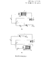
- FIG. 1 is a schematic view showing the system of an evaporative condensate pump supply liquid circulating hot and cold water unit of the present invention.
- Figure 2 shows the system schematic diagram of an evaporative condensate pump feed circulation circulating hot and cold water unit using a two-position three-way reversing valve.
- Fig. 3 is a schematic view showing the system of the vapor compression refrigeration cycle of the present invention, i.e., the system under summer refrigeration conditions.
- Figure 4 is a schematic view of the system of the vapor compression heat pump cycle of the present invention, i.e., the winter heat pump operating conditions.
- Figure 5 shows a system schematic diagram of an evaporative condensate pump feed-circulating chiller unit with multiple evaporators connected in parallel.
- Figure 6 shows a system schematic diagram of an evaporative condensate pump feed circulation chiller unit using a heat recovery unit.
- Fig. 7 is a schematic view showing the system of an evaporative condensate pump feed circulation circulating hot and cold water unit using a gravity feed switching valve.
- Fig. 8 is a schematic view showing the system of an evaporative condensate pump supply circulation circulating hot and cold water unit using a dry filter and a sight glass.
- FIG. 1 is a schematic diagram showing the system of an evaporative condensate pump feed liquid circulating hot and cold water unit according to the present invention, including a compressor 1, an evaporative condenser 2, a throttling device 3, a circulating liquid storage tank 4, and a liquid.
- the exhaust port of the compressor 1 is connected to the gas pipe 2a of the evaporative condenser 2 through the first refrigerating valve 11, the intake port of the compressor 1 and the top outlet of the circulating liquid storage tank 4 Connected; the liquid pipe 2b of the evaporative condenser 2 is sequentially connected to the lower inlet of the circulating liquid storage tank 4 through the second refrigerating valve 12 and the throttling device 3; the inlet of the liquid pump 5 and the circulating liquid storage tank 4 The bottom outlet is connected, the outlet of the liquid pump 5 is connected to the liquid pipe 6a of the evaporator 6 through the third refrigerating valve 13; the gas pipe 6b of the evaporator 6 is connected to the upper inlet of the circulating liquid storage tank 4 through the fourth refrigerating valve 14. .
- the unit further includes a first heat pump valve 21, a second heat pump valve 22, a third heat pump valve 23, and a fourth heat pump valve 24; an inlet of the first heat pump valve 21 and an exhaust port of the compressor 1 Connected, the outlet of the first heat pump valve 21 is connected to the gas pipe 6b of the evaporator 6; the inlet of the second heat pump valve 22 is connected to the liquid pipe 6a of the evaporator 6, and the outlet of the second heat pump valve 22 is passed through the section
- the flow device 3 is connected to the lower inlet of the circulating liquid storage tank 4; the inlet of the third heat pump valve 23 is connected to the outlet of the liquid pump 5, the outlet of the third heat pump valve 23 and the liquid pipe 2b of the evaporative condenser 2 The inlet of the fourth heat pump valve 24 is connected to the gas pipe 2a of the evaporative condenser 2, and the outlet of the fourth heat pump valve 24 is connected to the upper inlet of the circulating liquid storage tank 4.
- the four refrigeration valves 14 constitute a vapor compression refrigeration cycle; the compressor 1, the first heat pump valve 21, the evaporator 6, the second heat pump valve 22, the throttling device 3, the circulating liquid storage tank 4, the liquid pump 5,
- the third heat pump valve 23, the evaporative condenser 2, and the fourth heat pump valve 24 constitute a vapor compression heat pump cycle.
- the evaporative condensate pump supply liquid circulating hot and cold water unit of the first embodiment has two operation modes of a vapor compression refrigeration cycle and a vapor compression heat pump cycle.
- Fig. 3 is a schematic view showing the system of the vapor compression refrigeration cycle of the present invention, i.e., the system under summer refrigeration conditions.
- both the compressor 1 and the liquid pump 5 are operated; the first refrigeration valve 11, the second refrigeration valve 12, the third refrigeration valve 13, and the fourth refrigeration valve 14 are opened, and the first heat pump valve 21 is closed.
- the high-temperature high-pressure gas refrigerant enters the evaporative condenser 2 through the first refrigerating valve 11 and the gas tube 2a of the evaporating condenser 2, and is condensed into a high-pressure medium-temperature liquid; the high-pressure liquid refrigerant is evaporated in turn.
- the liquid tube 2b of the condenser, the second refrigerating valve 12, and the throttling device 3 are depressurized and then enter the circulating liquid storage tank 4; the liquid refrigerant in the circulating liquid storage tank 4 passes through the lower outlet of the circulating liquid storage tank 4,
- the liquid pump 5 is pressurized, and then sent to the evaporator 6 through the liquid pipe 6a of the third refrigeration valve 13 and the evaporator 6 in sequence, and exchanges with water or air to obtain cold water or cold air; the gas-liquid mixture of the refrigerant in turn
- the gas pipe 6b and the fourth refrigerating valve 14 of the evaporator 6 enter the circulating liquid storage tank 4, A vapor compression refrigeration cycle.
- Figure 4 is a schematic view of the system of the vapor compression heat pump cycle of the present invention, i.e., the winter heat pump operating conditions.
- the compressor 1 And liquid pump 5 are both running;
- the first heat pump valve 21, the second heat pump valve 22, the third heat pump valve 23, and the fourth heat pump valve 24 close the first refrigeration valve 11, the second refrigeration valve 12, the third refrigeration valve 13, and the fourth refrigeration Valve 14, at this time, the system performs a vapor compression heat pump cycle: the compressor 1 sucks the gaseous refrigerant in the circulating liquid storage tank 4, and compresses the gas into a high temperature and high pressure state; the high temperature and high pressure gaseous refrigerant passes through the first heat pump valve in turn. 21.
- the gas tube 6b of the evaporator 6 enters the evaporator 6, and is condensed and discharged into a high-pressure medium-temperature liquid; the high-pressure liquid refrigerant is sequentially depressurized by the liquid tube 6a of the evaporator, the second heat pump valve 22, and the throttling device 3. Entering the circulating liquid storage tank 4; the liquid refrigerant in the circulating liquid storage tank 4 passes through the lower outlet of the circulating liquid storage tank 4, is pressurized by the liquid pump 5, and then passes through the third heat pump valve 23 and the evaporative condenser 2 in sequence.
- the liquid pipe 2b is sent into the evaporative condenser 2, and is exchanged with water or air to obtain cold water or cold air; the gas-liquid mixture of the refrigerant is sequentially passed through the gas pipe 2a of the evaporative condenser 2, and the fourth heat pump valve. 24 enters the circulating liquid storage tank 4 to realize a vapor compression heat pump cycle.
- FIG. 2 A system schematic diagram of an evaporative condensate pump feed circulation circulating hot and cold water unit using a two-position three-way reversing valve is shown.
- the solution combines the first refrigerating valve 11 and the first heat pump valve 21 into a first two-position three-way reversing valve 31; the second refrigerating valve 12 and the third heat pump valve 23 are combined into a second two position a three-way reversing valve 32; the third refrigerating valve 13 and the second heat pump valve 22 are combined into a third two-position three-way reversing valve 33; the fourth refrigerating valve 14 and the fourth heat pump valve 24 are combined into a fourth two-position three-way switching valve 34; the first port 31a of the first two-position three-way switching valve 31 is connected to the exhaust port of the compressor 1, and the first two-position three-way switching valve 31 The two ports 31b are connected to the gas pipe 2a of the evaporative condenser 2, the third port 31c of the first two
- the evaporative condensate pump supply liquid circulating hot and cold water unit of the first embodiment still has two operation modes of a vapor compression refrigeration cycle and a vapor compression heat pump cycle.
- Fig. 3 is a schematic view showing the system of the vapor compression refrigeration cycle of the present invention, i.e., the system under summer refrigeration conditions.
- both the compressor 1 and the liquid pump 5 are operated.
- the system performs a vapor compression refrigeration cycle: the compressor 1 sucks the gaseous refrigerant in the circulating liquid storage tank 4, and compresses the gas into a high temperature and high pressure state;
- the high-temperature high-pressure gas refrigerant enters the evaporative condenser 2 through the first two-position three-way reversing valve 31 and the gas tube 2a of the evaporating condenser 2, and is condensed into a high-pressure medium-temperature liquid;
- the high-pressure liquid refrigerant is sequentially passed through The liquid tube 2b of the evaporative condenser, the second two-position three-way switching valve 32, and the throttling device 3 are depressurized and then enter the circulating liquid storage tank 4;
- FIG 4 is a schematic view of the system of the vapor compression heat pump cycle of the present invention, i.e., the winter heat pump operating conditions.
- the compressor 1 And liquid pump 5 are running At this time, the system performs a vapor compression heat pump cycle: the compressor 1 sucks the gaseous refrigerant in the circulating liquid storage tank 4, and compresses it into a gas at a high temperature and a high pressure state; the high temperature and high pressure gaseous refrigerant is sequentially exchanged through the first two-position three-way
- the gas pipe 6b of the valve 31 and the evaporator 6 enters the evaporator 6, and is condensed and discharged into a high-pressure medium-temperature liquid; the high-pressure liquid refrigerant sequentially passes through the liquid pipe 6a of the evaporator, the third two-position three-way switching valve 33, and the section.
- the flow device 3 After the flow device 3 is depressurized, it enters the circulating liquid storage tank 4; the liquid refrigerant in the circulating liquid storage tank 4 passes through the lower outlet of the circulating liquid storage tank 4, is pressurized by the liquid pump 5, and then passes through the second two-position three-way
- the reversing valve 32 and the liquid pipe 2b of the evaporative condenser 2 are sent into the evaporative condenser 2, and exchange heat with water or air to obtain cold water or cold air; the gas-liquid mixture of the refrigerant is sequentially passed through the evaporative condenser 2
- the gas pipe 2a and the fourth two-position three-way switching valve 34 enter the circulating liquid storage tank 4 to realize a vapor compression heat pump cycle.
- the evaporator 6 may be a way in which a plurality of evaporators are connected in parallel to meet the cooling requirements of single or multiple spaces.
- the evaporator 3 may employ a shell and tube evaporator and a finned evaporator.
- a heat recovery device 7 can be disposed at the exhaust port of the compressor 1, and a heat recovery technology is adopted in the summer cooling condition, and a hot water supply function is added in the winter heat pump working condition to realize the condensation heat. Recycling; the inlet of the heat recovery unit 7 is connected to the exhaust port of the compressor 1, and the outlet of the heat recovery unit 7 is connected to the inlet of the first refrigerating valve 11 and the inlet of the first heat pump valve 21, respectively, or The first port 31a of the one-two-position three-way switching valve 31.
- the gravity pump supply switching valve 8 can be connected in parallel to both ends of the liquid pump 5.
- the gravity feed liquid switching valve 8 is turned on, the liquid pump 5 is turned off, and the liquid is supplied by the gravity liquid supply mode; the liquid level of the liquid storage tank 4 to be circulated is stable, and the load of the compressor 1 reaches 60% or more.
- the gravity liquid supply switching valve 8 is closed and converted into a liquid pump supply liquid. This solution avoids the cavitation surge phenomenon of the liquid pump 5 due to the unstable liquid level of the circulating liquid storage tank 4.
- the evaporative condenser 2 may be a tube tube evaporative condenser or a coil type evaporative condenser.
- a lower condensing temperature is achieved and the system condensing pressure is reduced, thereby increasing the energy efficiency of the system.
- a desiccant filter 9 and a sight glass 10 are provided to form a complete refrigeration process line.
Landscapes
- Engineering & Computer Science (AREA)
- Physics & Mathematics (AREA)
- Mechanical Engineering (AREA)
- Thermal Sciences (AREA)
- General Engineering & Computer Science (AREA)
- Heat-Pump Type And Storage Water Heaters (AREA)
Description
技术领域
本 发明
涉及一种冷热水机组,尤其是一种适用于需全年空调冷暖供应的蒸发式冷凝液泵供液循环冷热水机组。
背景技术
目前的蒸气压缩式冷热水机组按照冷凝方式可分为风冷热泵机组、水冷热泵机组和地源热泵机组。风冷热泵机组是利用强制通风实现换热器与空气的热交换,在夏季气温较高时,热交换效率低,导致冷凝温度高,影响制冷系统的制冷效率;在冬季制热时室外换热器表面易结霜,耐低温能力差,这样不仅降低室外换热器的换热效率,而且机组需要除霜运行,大大减少了有效制热工作时间。水冷式制冷机组通过冷却水在水冷冷凝器内实现热交换,其不足之处是系统比较复杂,需要水泵和冷却塔的循环系统,且飞水和噪音影响严重。地源热泵对水源的水量和水质有较高要求,其应用时存在回灌和建筑地理条件的限制并需要大量的地下面积。因此,市场需要制热效率更高、不受地理条件限制的热泵技术。
此外,现有的蒸发器供液方式亦存在诸多不足,干式系统能效比偏低,满液式系统存在液位控制难和回油困难等问题,所以市场需要换热效率更高、更加安全可靠的蒸发器供液系统,提高蒸发器换热效率。
发明内容
本发明的目的是为克服上述现有技术存在的缺点和不足,提供一种换热效率高、使用安全可靠,并能在冬季免除霜、高效运行,以及可以提供免费生活热水的一种蒸发式冷凝液泵供液循环冷热水机组。
为解决上述技术问题,本发明是通过以下技术方案实现的:
一种蒸发式冷凝液泵供液循环冷热水机组,包括压缩机1、蒸发式冷凝器2、节流装置3、循环储液桶4、液泵5、蒸发器6;所述压缩机1的排气口通过第一制冷阀11与蒸发式冷凝器2的气体管2a连接,压缩机1的进气口与循环储液桶4的顶部出口连接;所述蒸发式冷凝器2的液体管2b依次通过第二制冷阀12和节流装置3与循环储液桶4的下部入口连接;所述液泵5的入口与循环储液桶4的底部出口连接,液泵5的出口通过第三制冷阀13与蒸发器6的液体管6a连接;所述蒸发器6的气体管6b通过第四制冷阀14与循环储液桶4的上部入口连接;该机组还包括第一热泵阀21、第二热泵阀22、第三热泵阀23和第四热泵阀24;所述第一热泵阀21的入口与压缩机1的排气口连接,第一热泵阀21的出口与蒸发器6的气体管6b连接;所述第二热泵阀22的入口与蒸发器6的液体管6a连接,第二热泵阀22的出口通过节流装置3与循环储液桶4的下部入口连接;所述第三热泵阀23的入口与液泵5的出口连接,第三热泵阀23的出口与蒸发式冷凝器2的液体管2b连接;所述第四热泵阀24的入口与蒸发式冷凝器2的气体管2a连接,第四热泵阀24的出口与循环储液桶4的上部入口连接;所述压缩机1、第一制冷阀11、蒸发式冷凝器2、第二制冷阀12、节流装置3、循环储液桶4、液泵5、第三制冷阀13、蒸发器6、第四制冷阀14组成蒸气压缩式制冷循环;所述压缩机1、第一热泵阀21、蒸发器6、第二热泵阀22、节流装置3、循环储液桶4、液泵5、第三热泵阀23、蒸发式冷凝器2、第四热泵阀24组成蒸气压缩式热泵循环。
作为本发明的一种改进,所述第一制冷阀11和第一热泵阀21合并为第一二位三通换向阀31;所述第二制冷阀12和第三热泵阀23合并为第二二位三通换向阀32;所述第三制冷阀13和第二热泵阀22合并为第三二位三通换向阀33;所述第四制冷阀14和第四热泵阀24合并为第四二位三通换向阀34;所述第一二位三通换向阀31的第一端口31a与压缩机1的排气口连接,第一二位三通换向阀31的第二端口31b与蒸发式冷凝器2的气体管2a连接,第一二位三通换向阀31的第三端口31c与蒸发器6的气体管6b连接;所述第二二位三通换向阀32的第一端口32a与蒸发式冷凝器2的液体管2b连接,第二二位三通换向阀32的第二端口32b与节流装置3的入口连接,第二二位三通换向阀32的第三端口32c与液泵5的出口连接;所述第三二位三通换向阀33的第一端口33a与液泵5的出口连接,第三二位三通换向阀33的第二端口33b与蒸发器6的液体管6a连接,第三二位三通换向阀33的第三端口33c与节流装置3的入口连接;所述第四二位三通换向阀34的第一端口34a与蒸发器6的气体管6b连接,第四二位三通换向阀34的第二端口34b与蒸发式冷凝器2的气体管2a连接,第四二位三通换向阀34的第三端口34c与循环储液桶4的上部入口连接。
作为本发明的一种改进,所述第一制冷阀11、第二制冷阀12、第三制冷阀13、第四制冷阀14、第一热泵阀21、第二热泵阀22、第三热泵阀23、第四热泵阀24采用电磁阀或电动阀。
作为本发明的一种改进,所述第一二位三通换向阀31、第二二位三通换向阀32、第三二位三通换向阀33、第四二位三通换向阀34采用电动二位三通换向阀或气动二位三通换向阀。
作为本发明的一种改进,所述压缩机1的排气口设置有热回收器7;所述热回收器7的入口与压缩机1的排气口连接,热回收器7的出口分别连接第一制冷阀11的入口和第一热泵阀21的入口,或者连接第一二位三通换向阀31的第一端口31a。
作为本发明的一种改进, 所述蒸发式冷凝器2采用板管蒸发式冷凝器或盘管式蒸发式冷凝器。
作为本发明的一种改进,所述蒸发器6采用壳管式蒸发器或翅片式蒸发器。
作为本发明的一种改进,所述蒸发器6采用多个并联方式连接。
作为本发明的一种改进,所述液泵5的两端并联有重力供液转换阀门8。
作为本发明的一种改进,所述蒸发式冷凝器2的出口与节流装置3的进口之间设置有干燥过滤器9和视液镜10。
与现有技术相比,本发明的有益效果是:
1
、本发明在夏季制冷工况时,采用液泵向蒸发器供液,实现蒸气压缩式制冷循环,提供更加安全可靠的蒸发器供液系统,比目前传统的干式蒸发器或满液式蒸发器具有更高的换热效率。
2
、本发明在冬季热泵工况时,通过二通阀或二位三通换向阀等转换阀门,实现蒸发器和蒸发式冷凝器功能相互转换,并由液泵向蒸发器或蒸发式冷凝器供液,提高其换热效率。此外,在蒸发式冷凝器中添加防冻剂后,可适用于比传统风冷热泵温度更低的工况,并能实现免除霜高效运行。
3
、本发明利用热回收器7收集压缩机1排出的废热,用以替代生活用锅炉供应生活用热水;相比于现有技术,本发明不仅可提供生活热水,还降低了机组的冷凝压力,节约运行成本;同时节省了锅炉与锅炉房的建设费用,大大节约了煤、油燃料费用,减轻了锅炉烟气对大气的污染。
附图说明
图1示出了本发明的一种蒸发式冷凝液泵供液循环冷热水机组的系统原理图。
图2 示出了采用二位三通换向阀的一种蒸发式冷凝液泵供液循环冷热水机组的系统原理图。
图3示意地示出了本发明的蒸气压缩式制冷循环,即夏季制冷工况下的系统原理图。
图4示意地示出了本发明的蒸气压缩式热泵循环 ,即冬季热泵工况下的系统原理图。
图 5 示出了采用多个蒸发器并联连接的 一种蒸发式冷凝液泵供液循环冷热水机组 的系统原理图。
图 6 示出了采用热回收器的一种蒸发式冷凝液泵供液循环冷热水机组的 系统原理图。
图7示出了采用 重力供液转换阀门的 一种蒸发式冷凝液泵供液循环冷热水机组 的 系统原理图。
图8示出了采用干燥过滤器和视液镜的一种蒸发式冷凝液泵供液循环冷热水机组 的 系统原理图。
图中:1压缩机、2蒸发式冷凝器、3节流装置、4循环储液桶、5液泵、6蒸发器、7热回收器、8
重力供液转换阀门、 9
干燥过滤器、10视液镜、11第一制冷阀、12第二制冷阀、13第三制冷阀、14第四制冷阀、21第一热泵阀、22第二热泵阀、23第三热泵阀、24第四热泵阀、31第一二位三通换向阀、32第二二位三通换向阀、33第三二位三通换向阀、34第四二位三通换向阀。
具体实施方式
实施例1
图1示出了本发明的一种蒸发式冷凝液泵供液循环冷热水机组的系统原理图,包括压缩机1、蒸发式冷凝器2、节流装置3、循环储液桶4、液泵5、蒸发器6;所述压缩机1的排气口通过第一制冷阀11与蒸发式冷凝器2的气体管2a连接,压缩机1的进气口与循环储液桶4的顶部出口连接;所述蒸发式冷凝器2的液体管2b依次通过第二制冷阀12和节流装置3与循环储液桶4的下部入口连接;所述液泵5的入口与循环储液桶4的底部出口连接,液泵5的出口通过第三制冷阀13与蒸发器6的液体管6a连接;所述蒸发器6的气体管6b通过第四制冷阀14与循环储液桶4的上部入口连接。
该机组还包括第一热泵阀21、第二热泵阀22、第三热泵阀23和第四热泵阀24;所述第一热泵阀21的入口与压缩机1的排气口连接,第一热泵阀21的出口与蒸发器6的气体管6b连接;所述第二热泵阀22的入口与蒸发器6的液体管6a连接,第二热泵阀22的出口通过节流装置3与循环储液桶4的下部入口连接;所述第三热泵阀23的入口与液泵5的出口连接,第三热泵阀23的出口与蒸发式冷凝器2的液体管2b连接;所述第四热泵阀24的入口与蒸发式冷凝器2的气体管2a连接,第四热泵阀24的出口与循环储液桶4的上部入口连接。
所述压缩机1、第一制冷阀11、蒸发式冷凝器2、第二制冷阀12、节流装置3、循环储液桶4、液泵5、第三制冷阀13、蒸发器6、第四制冷阀14组成蒸气压缩式制冷循环;所述压缩机1、第一热泵阀21、蒸发器6、第二热泵阀22、节流装置3、循环储液桶4、液泵5、第三热泵阀23、蒸发式冷凝器2、第四热泵阀24组成蒸气压缩式热泵循环。
所述实施例1的一种蒸发式冷凝液泵供液循环冷热水机组具有蒸气压缩式制冷循环和蒸气压缩式热泵循环两种运行模式。
图3示意地示出了本发明的蒸气压缩式制冷循环,即夏季制冷工况下的系统原理图。如图3所示,压缩机1和液泵5均运行;开启第一制冷阀11、第二制冷阀12、第三制冷阀13和第四制冷阀14,关闭第一热泵阀21、第二热泵阀22、第三热泵阀23和第四热泵阀24,此时系统进行蒸气压缩式制冷循环:压缩机1抽吸循环储液桶4内的气态制冷剂,压缩成高温高压状态的气体;高温高压的气态制冷剂依次经第一制冷阀11、蒸发式冷凝器2的气体管2a进入蒸发式冷凝器2,放热冷凝为高压中温的液体;高压液态制冷剂依次经蒸发式冷凝器的液体管2b、第二制冷阀12、节流装置3降压后进入循环储液桶4内;循环储液桶4内的液态制冷剂通过循环储液桶4的下部出口,经液泵5增压,再依次经第三制冷阀13、蒸发器6的液体管6a送入蒸发器6内,与水或空气进行热交换后制取冷水或冷风;制冷剂的气液混合物依次经蒸发器6的气体管6b、第四制冷阀14进入循环储液桶4内,实现蒸气压缩式制冷循环。
图4示意地示出了本发明的蒸气压缩式热泵循环 ,即冬季热泵工况下的系统原理图。如图 4 所示,压缩机 1
和液泵 5 均运行;开启
第一热泵阀21、第二热泵阀22、第三热泵阀23和第四热泵阀24,关闭第一制冷阀11、第二制冷阀12、第三制冷阀13和第四制冷阀14,此时系统进行蒸气压缩式热泵循环:压缩机1抽吸循环储液桶4内的气态制冷剂,压缩成高温高压状态的气体;高温高压的气态制冷剂依次经第一热泵阀21、蒸发器6的气体管6b进入蒸发器6,放热冷凝为高压中温的液体;高压液态制冷剂依次经蒸发器的液体管6a、第二热泵阀22、节流装置3降压后进入循环储液桶4内;循环储液桶4内的液态制冷剂通过循环储液桶4的下部出口,经液泵5增压,再依次经第三热泵阀23、蒸发式冷凝器2的液体管2b送入蒸发式冷凝器2内,与水或空气进行热交换后制取冷水或冷风;制冷剂的气液混合物依次经蒸发式冷凝器2的气体管2a、第四热泵阀24进入循环储液桶4内,实现蒸气压缩式热泵循环。
实施例2
图2
示出了采用二位三通换向阀的一种蒸发式冷凝液泵供液循环冷热水机组的系统原理图。该方案将所述第一制冷阀11和第一热泵阀21合并为第一二位三通换向阀31;所述第二制冷阀12和第三热泵阀23合并为第二二位三通换向阀32;所述第三制冷阀13和第二热泵阀22合并为第三二位三通换向阀33;所述第四制冷阀14和第四热泵阀24合并为第四二位三通换向阀34;所述第一二位三通换向阀31的第一端口31a与压缩机1的排气口连接,第一二位三通换向阀31的第二端口31b与蒸发式冷凝器2的气体管2a连接,第一二位三通换向阀31的第三端口31c与蒸发器6的气体管6b连接;所述第二二位三通换向阀32的第一端口32a与蒸发式冷凝器2的液体管2b连接,第二二位三通换向阀32的第二端口32b与节流装置3的入口连接,第二二位三通换向阀32的第三端口32c与液泵5的出口连接;所述第三二位三通换向阀33的第一端口33a与液泵5的出口连接,第三二位三通换向阀33的第二端口33b与蒸发器6的液体管6a连接,第三二位三通换向阀33的第三端口33c与节流装置3的入口连接;所述第四二位三通换向阀34的第一端口34a与蒸发器6的气体管6b连接,第四二位三通换向阀34的第二端口34b与蒸发式冷凝器2的气体管2a连接,第四二位三通换向阀34的第三端口34c与循环储液桶4的上部入口连接。
所述实施例1的一种蒸发式冷凝液泵供液循环冷热水机组仍然具有蒸气压缩式制冷循环和蒸气压缩式热泵循环两种运行模式。
图3示意地示出了本发明的蒸气压缩式制冷循环,即夏季制冷工况下的系统原理图。如图3所示,压缩机1和液泵5均运行,此时系统进行蒸气压缩式制冷循环:压缩机1抽吸循环储液桶4内的气态制冷剂,压缩成高温高压状态的气体;高温高压的气态制冷剂依次经第一二位三通换向阀31、蒸发式冷凝器2的气体管2a进入蒸发式冷凝器2,放热冷凝为高压中温的液体;高压液态制冷剂依次经蒸发式冷凝器的液体管2b、第二二位三通换向阀32、节流装置3降压后进入循环储液桶4内;循环储液桶4内的液态制冷剂通过循环储液桶4的下部出口,经液泵5增压,再依次经第三二位三通换向阀33、蒸发器6的液体管6a送入蒸发器6内,与水或空气进行热交换后制取冷水或冷风;制冷剂的气液混合物依次经蒸发器6的气体管6b、第四二位三通换向阀34进入循环储液桶4内,实现蒸气压缩式制冷循环。
图4示意地示出了本发明的蒸气压缩式热泵循环 ,即冬季热泵工况下的系统原理图。如图 4 所示,压缩机 1
和液泵 5 均运行
,此时系统进行蒸气压缩式热泵循环:压缩机1抽吸循环储液桶4内的气态制冷剂,压缩成高温高压状态的气体;高温高压的气态制冷剂依次经第一二位三通换向阀31、蒸发器6的气体管6b进入蒸发器6,放热冷凝为高压中温的液体;高压液态制冷剂依次经蒸发器的液体管6a、第三二位三通换向阀33、节流装置3降压后进入循环储液桶4内;循环储液桶4内的液态制冷剂通过循环储液桶4的下部出口,经液泵5增压,再依次经第二二位三通换向阀32、蒸发式冷凝器2的液体管2b送入蒸发式冷凝器2内,与水或空气进行热交换后制取冷水或冷风;制冷剂的气液混合物依次经蒸发式冷凝器2的气体管2a、第四二位三通换向阀34进入循环储液桶4内,实现蒸气压缩式热泵循环。
如图5所示,所述蒸发器6可以是多个蒸发器并联连接的方式,以满足单个或多个空间的供冷需求。作为优选,蒸发器3可以采用壳管式蒸发器和翅片式蒸发器。
如图6所示,在所述压缩机1的排气口可设置热回收器7,在夏季制冷工况时采用热回收技术,在冬季热泵工况时则增加热水供应功能,实现冷凝热的回收利用;所述热回收器7的入口与压缩机1的排气口连接,热回收器7的出口分别连接第一制冷阀11的入口和第一热泵阀21的入口,或者连接第一二位三通换向阀31的第一端口31a。
如图7所示,所述液泵5两端可以并联重力供液转换阀门8。压缩机6制冷刚启动时,开启重力供液转换阀门8,关闭液泵5,以重力供液方式供液;待循环储液桶4的液位稳定,且压缩机1的负荷达到60%以上时,开启液泵5,关闭重力供液转换阀门8,转换为液泵供液。此方案避免了由于循环储液桶4液位不稳定而造成液泵5的汽蚀喘振现象。此外,也可在部分负荷或供液泵5发生故障时实现不运行供液泵5而采用重力供液方式直接向蒸发器6或蒸发式冷凝器2供液运行。
作为优选,所述蒸发式冷凝器2可以采用 板管蒸发式冷凝器或盘管式蒸发式冷凝器,
可获得更低的冷凝温度,并可降低系统冷凝压力,从而提高系统的能效比。
如图8所示,在蒸发式冷凝器2的出口与节流装置3的进口之间设置有干燥过滤器9和视液镜10,组成完善的制冷工艺管路。
显然,本发明不限于以上实施例,还可以有许多变形。本领域的普通技术人员能从本发明公开的内容直接导出或联想到的所有变形,均应认为是本发明的保护范围。
Claims (10)
- 一种蒸发式冷凝液泵供液循环冷热水机组,包括压缩机(1)、蒸发式冷凝器(2)、节流装置(3)、循环储液桶(4)、液泵(5)、蒸发器(6);所述压缩机(1)的排气口通过第一制冷阀(11)与蒸发式冷凝器(2)的气体管(2a)连接,压缩机(1)的进气口与循环储液桶(4)的顶部出口连接;所述蒸发式冷凝器(2)的液体管(2b)依次通过第二制冷阀(12)和节流装置(3)与循环储液桶(4)的下部入口连接;所述液泵(5)的入口与循环储液桶(4)的底部出口连接,液泵(5)的出口通过第三制冷阀(13)与蒸发器(6)的液体管(6a)连接;所述蒸发器(6)的气体管(6b)通过第四制冷阀(14)与循环储液桶(4)的上部入口连接,其特征在于:该机组还包括第一热泵阀(21)、第二热泵阀(22)、第三热泵阀(23)和第四热泵阀(24);所述第一热泵阀(21)的入口与压缩机(1)的排气口连接,第一热泵阀(21)的出口与蒸发器(6)的气体管(6b)连接;所述第二热泵阀(22)的入口与蒸发器(6)的液体管(6a)连接,第二热泵阀(22)的出口通过节流装置(3)与循环储液桶(4)的下部入口连接;所述第三热泵阀(23)的入口与液泵(5)的出口连接,第三热泵阀(23)的出口与蒸发式冷凝器(2)的液体管(2b)连接;所述第四热泵阀(24)的入口与蒸发式冷凝器(2)的气体管(2a)连接,第四热泵阀(24)的出口与循环储液桶(4)的上部入口连接;所述压缩机(1)、第一制冷阀(11)、蒸发式冷凝器(2)、第二制冷阀(12)、节流装置(3)、循环储液桶(4)、液泵(5)、第三制冷阀(13)、蒸发器(6)、第四制冷阀(14)组成蒸气压缩式制冷循环;所述压缩机(1)、第一热泵阀(21)、蒸发器(6)、第二热泵阀(22)、节流装置(3)、循环储液桶(4)、液泵(5)、第三热泵阀(23)、蒸发式冷凝器(2)、第四热泵阀(24)组成蒸气压缩式热泵循环。
- 根据权利要求1所述的一种蒸发式冷凝液泵供液循环冷热水机组,其特征在于:所述第一制冷阀(11)和第一热泵阀(21)合并为第一二位三通换向阀(31);所述第二制冷阀(12)和第三热泵阀(23)合并为第二二位三通换向阀(32);所述第三制冷阀(13)和第二热泵阀(22)合并为第三二位三通换向阀(33);所述第四制冷阀(14)和第四热泵阀(24)合并为第四二位三通换向阀(34);所述第一二位三通换向阀(31)的第一端口(31a)与压缩机(1)的排气口连接,第一二位三通换向阀(31)的第二端口(31b)与蒸发式冷凝器(2)的气体管(2a)连接,第一二位三通换向阀(31)的第三端口(31c)与蒸发器(6)的气体管(6b)连接;所述第二二位三通换向阀(32)的第一端口(32a)与蒸发式冷凝器(2)的液体管(2b)连接,第二二位三通换向阀(32)的第二端口(32b)与节流装置(3)的入口连接,第二二位三通换向阀(32)的第三端口(32c)与液泵(5)的出口连接;所述第三二位三通换向阀(33)的第一端口(33a)与液泵(5)的出口连接,第三二位三通换向阀(33)的第二端口(33b)与蒸发器(6)的液体管(6a)连接,第三二位三通换向阀(33)的第三端口(33c)与节流装置(3)的入口连接;所述第四二位三通换向阀(34)的第一端口(34a)与蒸发器(6)的气体管(6b)连接,第四二位三通换向阀(34)的第二端口(34b)与蒸发式冷凝器(2)的气体管(2a)连接,第四二位三通换向阀(34)的第三端口(34c)与循环储液桶(4)的上部入口连接。
- 根据权利要求1或2所述的一种蒸发式冷凝液泵供液循环冷热水机组,其特征在于:所述第一制冷阀(11)、第二制冷阀(12)、第三制冷阀(13)、第四制冷阀(14)、第一热泵阀(21)、第二热泵阀(22)、第三热泵阀(23)、第四热泵阀(24)采用电磁阀或电动阀。
- 根据权利要求2所述的一种蒸发式冷凝液泵供液循环冷热水机组,其特征在于:所述第一二位三通换向阀(31)、第二二位三通换向阀(32)、第三二位三通换向阀(33)、第四二位三通换向阀(34)采用电动二位三通换向阀或气动二位三通换向阀。
- 根据权利要求1或2所述的一种蒸发式冷凝液泵供液循环冷热水机组,其特征在于:所述压缩机(1)的排气口设置有热回收器(7);所述热回收器(7)的入口与压缩机(1)的排气口连接,热回收器(7)的出口分别连接第一制冷阀(11)的入口和第一热泵阀(21)的入口,或者连接第一二位三通换向阀(31)的第一端口(31a)。
- 根据权利要求1或2所述的一种蒸发式冷凝液泵供液循环冷热水机组,其特征在于: 所述蒸发式冷凝器(2)采用板管蒸发式冷凝器或盘管式蒸发式冷凝器。
- 根据权利要求1或2所述的一种蒸发式冷凝液泵供液循环冷热水机组,其特征在于: 所述蒸发器(6)采用壳管式蒸发器或翅片式蒸发器。
- 根据权利要求1或2所述的一种蒸发式冷凝液泵供液循环冷热水机组,其特征在于: 所述蒸发器(6)采用多个并联方式连接。
- 根据权利要求1或2所述的一种蒸发式冷凝液泵供液循环冷热水机组,其特征在于:所述液泵(5)的两端并联有重力供液转换阀门(8)。
- 根据权利要求1或2所述的一种蒸发式冷凝液泵供液循环冷热水机组,其特征在于:所述蒸发式冷凝器(2)的出口与节流装置(3)的进口之间设置有干燥过滤器(9)和视液镜(10)。
Applications Claiming Priority (2)
| Application Number | Priority Date | Filing Date | Title |
|---|---|---|---|
| CN201010244119.5 | 2010-08-03 | ||
| CN2010102441195A CN101936614B (zh) | 2010-08-03 | 2010-08-03 | 一种蒸发式冷凝液泵供液循环冷热水机组 |
Publications (1)
| Publication Number | Publication Date |
|---|---|
| WO2012016452A1 true WO2012016452A1 (zh) | 2012-02-09 |
Family
ID=43390074
Family Applications (1)
| Application Number | Title | Priority Date | Filing Date |
|---|---|---|---|
| PCT/CN2011/073170 Ceased WO2012016452A1 (zh) | 2010-08-03 | 2011-04-22 | 液泵供液冷热水机组 |
Country Status (3)
| Country | Link |
|---|---|
| CN (1) | CN101936614B (zh) |
| HK (1) | HK1148642A2 (zh) |
| WO (1) | WO2012016452A1 (zh) |
Cited By (1)
| Publication number | Priority date | Publication date | Assignee | Title |
|---|---|---|---|---|
| US12578124B2 (en) | 2018-08-29 | 2026-03-17 | Waterfurnace International, Inc. | Integrated demand water heating using a capacity modulated heat pump with desuperheater |
Families Citing this family (6)
| Publication number | Priority date | Publication date | Assignee | Title |
|---|---|---|---|---|
| CN101936614B (zh) * | 2010-08-03 | 2013-03-06 | 广州市华德工业有限公司 | 一种蒸发式冷凝液泵供液循环冷热水机组 |
| CN102563947B (zh) * | 2012-03-22 | 2016-06-01 | 北京德能恒信科技有限公司 | 一种热管热泵组合型制冷装置 |
| CN103574965B (zh) * | 2012-07-20 | 2016-12-21 | 广州市华德工业有限公司 | 一种带填料耦合盘管蒸发式冷凝器的冷水机组 |
| CN112594949B (zh) * | 2020-12-14 | 2022-11-15 | 广州兰石技术开发有限公司 | 节能型焓差试验室 |
| CN112556225B (zh) * | 2020-12-14 | 2022-08-09 | 广州兰石技术开发有限公司 | 桶泵制冷系统 |
| CN117082828A (zh) * | 2023-08-21 | 2023-11-17 | 东北大学 | 一种能防止泵气蚀的热管/蒸气压缩空调系统及控制方法 |
Citations (7)
| Publication number | Priority date | Publication date | Assignee | Title |
|---|---|---|---|---|
| US5056329A (en) * | 1990-06-25 | 1991-10-15 | Battelle Memorial Institute | Heat pump systems |
| CN1342878A (zh) * | 2001-09-29 | 2002-04-03 | 朱健平 | 内液式制冷(热泵)循环系统 |
| CN2901183Y (zh) * | 2006-04-14 | 2007-05-16 | 广东美的电器股份有限公司 | 一种热泵型空调器 |
| CN2929590Y (zh) * | 2006-06-19 | 2007-08-01 | 山东威特人工环境有限公司 | 一种风冷热泵空调系统 |
| JP2009222248A (ja) * | 2008-03-13 | 2009-10-01 | Aisin Seiki Co Ltd | 空気調和装置及びそのアキュムレータ |
| CN101936614A (zh) * | 2010-08-03 | 2011-01-05 | 广州市华德工业有限公司 | 一种蒸发式冷凝液泵供液循环冷热水机组 |
| CN201757537U (zh) * | 2010-08-03 | 2011-03-09 | 广州市华德工业有限公司 | 一种蒸发式冷凝液泵供液循环冷热水机组 |
-
2010
- 2010-08-03 CN CN2010102441195A patent/CN101936614B/zh active Active
-
2011
- 2011-04-22 WO PCT/CN2011/073170 patent/WO2012016452A1/zh not_active Ceased
- 2011-05-17 HK HK11104835.8A patent/HK1148642A2/zh not_active IP Right Cessation
Patent Citations (7)
| Publication number | Priority date | Publication date | Assignee | Title |
|---|---|---|---|---|
| US5056329A (en) * | 1990-06-25 | 1991-10-15 | Battelle Memorial Institute | Heat pump systems |
| CN1342878A (zh) * | 2001-09-29 | 2002-04-03 | 朱健平 | 内液式制冷(热泵)循环系统 |
| CN2901183Y (zh) * | 2006-04-14 | 2007-05-16 | 广东美的电器股份有限公司 | 一种热泵型空调器 |
| CN2929590Y (zh) * | 2006-06-19 | 2007-08-01 | 山东威特人工环境有限公司 | 一种风冷热泵空调系统 |
| JP2009222248A (ja) * | 2008-03-13 | 2009-10-01 | Aisin Seiki Co Ltd | 空気調和装置及びそのアキュムレータ |
| CN101936614A (zh) * | 2010-08-03 | 2011-01-05 | 广州市华德工业有限公司 | 一种蒸发式冷凝液泵供液循环冷热水机组 |
| CN201757537U (zh) * | 2010-08-03 | 2011-03-09 | 广州市华德工业有限公司 | 一种蒸发式冷凝液泵供液循环冷热水机组 |
Cited By (1)
| Publication number | Priority date | Publication date | Assignee | Title |
|---|---|---|---|---|
| US12578124B2 (en) | 2018-08-29 | 2026-03-17 | Waterfurnace International, Inc. | Integrated demand water heating using a capacity modulated heat pump with desuperheater |
Also Published As
| Publication number | Publication date |
|---|---|
| CN101936614A (zh) | 2011-01-05 |
| CN101936614B (zh) | 2013-03-06 |
| HK1148642A2 (zh) | 2011-09-09 |
Similar Documents
| Publication | Publication Date | Title |
|---|---|---|
| CN205678804U (zh) | 一种带有自然冷却功能的风冷冷水机组和空调器 | |
| CN112097356A (zh) | 一种氟泵型机房风冷精密空调 | |
| WO2024198359A1 (zh) | 一种超低温单双级混合式空气源热泵机组 | |
| CN105402966B (zh) | 一种太阳能空气源热泵 | |
| CN108759138B (zh) | 二次节流中间不完全冷却制冷系统的运行方法及系统 | |
| CN205747570U (zh) | 蒸发式冷凝空调热泵系统 | |
| CN103615836B (zh) | 一种螺杆式全热回收风冷热泵空调机组 | |
| CN205316766U (zh) | 一种太阳能空气源热泵 | |
| WO2011113295A1 (zh) | 多功能空调、热水系统 | |
| CN105571198A (zh) | 一种基于蓄冷过冷的高效制冷系统 | |
| CN101936614B (zh) | 一种蒸发式冷凝液泵供液循环冷热水机组 | |
| CN210638220U (zh) | 一种喷射制冷和露点蒸发冷却复合的空调系统 | |
| CN106196678A (zh) | 一种带喷射器的泵驱动双蒸发器基站散热装置 | |
| CN110030765A (zh) | 一种干燥供暖供冷复合系统 | |
| CN117870204A (zh) | 蒸发冷低温型全热回收风冷热泵机组 | |
| CN201392047Y (zh) | 多机并联分压蒸发冷(热)水机组 | |
| CN108759139B (zh) | 具有中温蒸发器的一次节流中间不完全冷却的制冷系统 | |
| CN110701819A (zh) | 一种三工况系统 | |
| CN222978384U (zh) | 一种多功能高效除霜蒸发冷热泵机组 | |
| CN210123212U (zh) | 一种干燥供暖供冷复合系统 | |
| CN110145914B (zh) | 一种引入自然冷源的家用冰箱 | |
| CN219550878U (zh) | 改进型低温空气源冷暖热泵 | |
| CN203848548U (zh) | 空气源热泵多用机组 | |
| CN116678136B (zh) | 一种耦合双除霜方式的热泵系统及其运行方法 | |
| CN220453980U (zh) | 一种蒸发冷凝热管空调机组 |
Legal Events
| Date | Code | Title | Description |
|---|---|---|---|
| 121 | Ep: the epo has been informed by wipo that ep was designated in this application |
Ref document number: 11814036 Country of ref document: EP Kind code of ref document: A1 |
|
| NENP | Non-entry into the national phase |
Ref country code: DE |
|
| 122 | Ep: pct application non-entry in european phase |
Ref document number: 11814036 Country of ref document: EP Kind code of ref document: A1 |