WO2012015279A2 - 다중안테나 시스템에서 다중 섹터 협력 전송을 위한 송신 빔포밍과 다중 사용자 스케줄링 방법 및 장치 - Google Patents
다중안테나 시스템에서 다중 섹터 협력 전송을 위한 송신 빔포밍과 다중 사용자 스케줄링 방법 및 장치 Download PDFInfo
- Publication number
- WO2012015279A2 WO2012015279A2 PCT/KR2011/005629 KR2011005629W WO2012015279A2 WO 2012015279 A2 WO2012015279 A2 WO 2012015279A2 KR 2011005629 W KR2011005629 W KR 2011005629W WO 2012015279 A2 WO2012015279 A2 WO 2012015279A2
- Authority
- WO
- WIPO (PCT)
- Prior art keywords
- user
- transmission
- sector
- transmission mode
- users
- Prior art date
- Legal status (The legal status is an assumption and is not a legal conclusion. Google has not performed a legal analysis and makes no representation as to the accuracy of the status listed.)
- Ceased
Links
Images


Classifications
-
- H—ELECTRICITY
- H04—ELECTRIC COMMUNICATION TECHNIQUE
- H04B—TRANSMISSION
- H04B7/00—Radio transmission systems, i.e. using radiation field
- H04B7/02—Diversity systems; Multi-antenna system, i.e. transmission or reception using multiple antennas
- H04B7/04—Diversity systems; Multi-antenna system, i.e. transmission or reception using multiple antennas using two or more spaced independent antennas
- H04B7/0491—Diversity systems; Multi-antenna system, i.e. transmission or reception using multiple antennas using two or more spaced independent antennas using two or more sectors, i.e. sector diversity
-
- H—ELECTRICITY
- H04—ELECTRIC COMMUNICATION TECHNIQUE
- H04B—TRANSMISSION
- H04B7/00—Radio transmission systems, i.e. using radiation field
- H04B7/02—Diversity systems; Multi-antenna system, i.e. transmission or reception using multiple antennas
- H04B7/04—Diversity systems; Multi-antenna system, i.e. transmission or reception using multiple antennas using two or more spaced independent antennas
- H04B7/0413—MIMO systems
- H04B7/0452—Multi-user MIMO systems
-
- H—ELECTRICITY
- H04—ELECTRIC COMMUNICATION TECHNIQUE
- H04B—TRANSMISSION
- H04B7/00—Radio transmission systems, i.e. using radiation field
- H04B7/02—Diversity systems; Multi-antenna system, i.e. transmission or reception using multiple antennas
- H04B7/04—Diversity systems; Multi-antenna system, i.e. transmission or reception using multiple antennas using two or more spaced independent antennas
- H04B7/06—Diversity systems; Multi-antenna system, i.e. transmission or reception using multiple antennas using two or more spaced independent antennas at the transmitting station
- H04B7/0613—Diversity systems; Multi-antenna system, i.e. transmission or reception using multiple antennas using two or more spaced independent antennas at the transmitting station using simultaneous transmission
- H04B7/0615—Diversity systems; Multi-antenna system, i.e. transmission or reception using multiple antennas using two or more spaced independent antennas at the transmitting station using simultaneous transmission of weighted versions of same signal
- H04B7/0617—Diversity systems; Multi-antenna system, i.e. transmission or reception using multiple antennas using two or more spaced independent antennas at the transmitting station using simultaneous transmission of weighted versions of same signal for beam forming
Definitions
- the present invention relates to a multi-antenna system, and more particularly, to a transmission beamforming and a multi-user scheduling method and apparatus for multi-sector cooperative transmission in a wireless communication system using multiple antennas.
- a multi-sector wireless communication system In a multi-sector wireless communication system, downlink system performance of a sector boundary is severely degraded by neighboring sector interference. Therefore, it is essential to eliminate neighboring sector interference.
- the base station uses adjacent sectors through multi-sector cooperative coherent beamforming or multi-sector cooperative eigen beamforming, which is based on instantaneous or average channel information of sector boundary users. Performance gain can be obtained by eliminating interference.
- the single beamforming technique such as the multi-sector cooperative matched beamforming or the sector co-operated unique beamforming reduces the number of users supported per sector by half because two sectors cooperate to serve only one user in the multi-sector. The disadvantage is that the overall system performance is degraded.
- ZF zero-forcing
- MMSE minimum mean square error
- the ZF or the MMSE can solve the problems of existing multi-sector cooperative matched beamforming or unique beamforming by reducing spatial interference and gaining spatial multiplexing gain through multi-sector cooperative transmission.
- the ZF or the MMSE-based sector cooperative beamforming technique is based only on instantaneous channel information, there is a disadvantage in that it is very vulnerable to a channel mismatch problem due to the speed and sounding error of the user.
- An object of the present invention is to provide a transmission beamforming and a multi-user scheduling method and apparatus for multi-sector cooperative transmission in a multi-antenna system.
- Another object of the present invention is to provide a multi-sector cooperative transmission method and apparatus for reducing system performance degradation due to a channel mismatch problem due to a user's speed and sounding error in a multi-antenna system.
- Another object of the present invention is to provide a scheduling method and apparatus for multi-user multi-sector cooperative transmission in order to maximize system capacity in a multi-antenna system.
- a transmission beamforming method for multi-sector cooperative transmission in a multi-antenna system comprising the steps of determining the transmission mode of the sector boundary users according to the channel environment; Determining a multi-sector cooperative transmission beam capable of supporting multiple users based on the transmission mode of the user, and considering a determined multi-sector cooperative transmission beam, determining a user combination for multi-sector cooperative beamforming; And performing the sector cooperative transmission beamforming with the determined user combination.
- a transmission beamforming apparatus for multi-sector cooperative transmission in a multi-antenna system, comprising: a transmission mode determiner for determining a transmission mode of sector boundary users according to a channel environment; And a weight determiner for determining a multi-sector cooperative transmission beam based on the transmission mode of the user, and a user combination for multi-sector cooperative beamforming in consideration of the determined multi-sector cooperative transmission beam. And an RF preprocessor for performing sector cooperative transmission beamforming with the determined user combination.
- the present invention utilizes this feature to provide sector boundary users with an average channel sector cooperation with Instantaneous Channel Sector Cooperation (ISC) users according to speed, sounding error and transmit antenna spatial correlation.
- ISC Instantaneous Channel Sector Cooperation
- SSC Simulation channel Sector Cooperation
- FIG. 1 is a diagram showing a system environment for multi-sector cooperative transmission in a multi-antenna system according to an embodiment of the present invention
- FIG. 2 is a diagram of a base station apparatus for multi-sector cooperative transmission in a multi-antenna system according to an embodiment of the present invention
- FIG. 3 is a flowchart illustrating an operation of a base station for multi-sector cooperative transmission in a multi-antenna system according to an embodiment of the present invention
- FIG. 4 is a flowchart illustrating an operation of a terminal for multi-sector cooperative transmission in a multi-antenna system according to an exemplary embodiment of the present invention.
- FIG. 5 is a graph showing the performance of each transmission mode according to the size of the transmission antenna spatial correlation diagram according to an embodiment of the present invention
- FIG. 6 is a graph showing performance of each transmission mode according to a user speed according to an embodiment of the present invention.
- FIG. 7 is a graph showing the performance of the proposed scheme according to the number of users K according to an embodiment of the present invention.
- the present invention will be described a transmission beamforming and a multi-user scheduling method and apparatus for multi-sector cooperative transmission in a multi-antenna system.
- the present invention relates to an Instantaneous Channel Sector Cooperation (ISC) user and an Average Channel Sector Cooperation (SSC) according to the speed, sounding error, and transmission antenna spatial correlation of the sector boundary user.
- ISC Instantaneous Channel Sector Cooperation
- SSC Average Channel Sector Cooperation
- a technique of transmitting a signal by forming multiple transmission beams that can be divided into users and simultaneously support users having different user speeds and different transmission antenna spatial correlations will be described.
- a technique of determining an optimal number of users and a combination of users to perform multi-sector cooperative beamforming without distinguishing between ISC and SSC users through the multiple transmission beams will be described.
- FIG. 1 illustrates a system environment for multi-sector cooperative transmission in a multi-antenna system according to an embodiment of the present invention.
- a downlink of a multi-sector multi-user cellular system using multiple antennas with transmit antenna channel correlation exists. It is assumed that K user terminals equipped with a single receive antenna are distributed at sector boundaries, and each sector of the base station has M transmit antennas. In addition, it is assumed that the base station schedules and transmits L ( ⁇ 2M) users among a total of K user terminals at an arbitrary scheduling time through cooperation of two adjacent sectors.
- Sector And user terminal Defined as the channel path loss value between two sectors that perform sector cooperation , And user terminals Channel vector between Is expressed by Equation 1 below.
- the channel vector may be represented as in Equation 2.
- the base station is the channel vector User terminal This can be obtained through the transmitted channel sounding signal, where the base station and the user terminal Channel estimation vector between May be represented as in Equation 4 below.
- MSE Mean Mean Error
- Equation 5 Delay channel vector Sounding error , Transmit time delay, and transmit antenna spatial correlation All of them can be expressed as shown in Equation 7.
- the present invention has a sounding error , Transmission time delay And transmit antenna spatial correlation Channel vector considering all This paper analyzes the beamforming gain and the amount of interference that can be obtained by a sector boundary user through multi-sector cooperative transmission, and proposes a transmission beamforming and a multi-user scheduling method and apparatus for multi-sector cooperative transmission.
- the multi-sector cooperative beamforming technique based on instantaneous channel information has an advantage that a beamforming gain of up to 2M times can be obtained when the user's speed is low or there is no channel mismatch due to sounding errors.
- the performance of the beamforming gain decreases and the performance of the multi-beam residual interference increases in proportion to the transmission delay and channel estimation error.
- the multi-sector cooperative beamforming method based on average channel information is robust to the user's channel mismatch problem and transmit antenna correlation matrix Eigenvalues generated by Eigen-Value Decomposition (EVD) Maximum Eigenvalue of Values There is an advantage that a beamforming gain can be obtained.
- ELD Eigen-Value Decomposition
- the capacity that can be obtained is limited than the multi-sector cooperative technique based on instantaneous channel information.
- the present invention provides a sounding error of the user terminals of the sector boundary as shown in FIG. 1 to obtain an optimal transmission performance according to the channel environment of the user. , Transmission time delay And transmit antenna spatial correlation In consideration of this, it is classified into ISC mode and SSC mode. In this case, the present invention is a transmission mode of each user based on the expected value of the maximum received signal-to-interference plus noise ratio (SINR) that can be obtained when each user operates in ISC mode or SSC mode. Determine.
- SINR maximum received signal-to-interference plus noise ratio
- FIG. 2 illustrates a base station apparatus for multi-sector cooperative transmission in a multi-antenna system according to an exemplary embodiment of the present invention.
- the pilot symbol extractor 213 extracts a pilot symbol or sounding symbol from the received signal and provides the extracted pilot symbol or sounding symbol to the channel estimator 214, and the channel estimator 214 provides a pilot symbol or sound from the pilot symbol extractor 213. Using the ding symbol, channel estimation is performed and the result is provided to the data demodulator 216.
- the data symbol extractor 215 extracts a data symbol from a received signal and provides the data symbol to the data demodulator 216.
- the data demodulator 216 is based on a channel estimation result from the channel estimator 214. Demodulate data symbols from data symbol extractor 215.
- the uplink control signal extractor 208 extracts an uplink control signal from the received signal, and transmits the uplink control signal to the user transmission mode collector 209, the transmit antenna spatial correlation collector 210, the signal-to-noise ratio collector 212, and the like. Provide control information (CQI, ACK / NAC, HARQ, etc.).
- the uplink control signal extractor 208 receives the transmission mode (ISC, SSC) information of the user determined by the transmission mode determiner 201 and provides it to the user transmission mode collector 209. do.
- the user transmission mode collector 209 may be directly provided with transmission mode information for each user from the transmission mode determiner 201.
- the uplink control signal extractor 208 receives channel matrix information from the channel estimator 214 and provides the transmission antenna correlation collector 210.
- the transmit antenna correlation collector 210 may be provided with channel matrix information for each user directly from the channel estimator 214.
- the uplink control signal extractor 208 determines the ratio of the intensity of the received signal to the measured noise for each user, and provides the result to the signal-to-noise ratio collector 212.
- the uplink control signal extractor 208 determines the speed of the user terminal and provides the result to the transmission mode determiner 201.
- the uplink control signal extractor 208 may measure the speed of the user terminal using the Doppler frequency, and may use a well-known conventional terminal speed measuring technique.
- the user transmission mode collector 209 collects user-specific transmission modes and provides the collected user transmission mode information to the weight determiner 202, and the transmission antenna spatial correlation collector 210 based on a channel matrix.
- the transmission antenna spatial correlation for each user is determined, and the result is provided to the weight determiner 202 and the transmission mode determiner 201, and the signal-to-noise ratio collector 212 measures the strength and measurement of the received signal for each user.
- the ratio of the intensity of the noise is collected, and the collected signal-to-noise ratio of the user is provided to the weight determiner 202.
- the transmission mode determiner 201 is a sounding error for the user terminals of the sector boundary , Transmission time delay And transmit antenna spatial correlation In consideration of this, it is classified into ISC mode and SSC mode.
- the present invention is a transmission mode of each user based on the expected value of the maximum received signal-to-interference plus noise ratio (SINR) that can be obtained when each user operates in ISC mode or SSC mode. Determine.
- SINR maximum received signal-to-interference plus noise ratio
- the transmission mode determiner 201 determines the transmission mode of each user as shown in Equation 10 based on the expected value of the maximum SINR that can be obtained when multiple users operate in the ISC mode or the SSC mode.
- the transmission mode determiner 201 determines the transmission mode.
- the base station determines multiple transmission beams capable of simultaneously serving heterogeneous mode users as well as homogeneous mode in consideration of the speed, sounding error, and transmission antenna spatial correlation of users.
- the present invention is a user terminal Transmit beam Through the user terminal While this beamforming gain can be maximized This amount of multi-user interference caused is minimized Determine.
- L users are served simultaneously. Is the number of SSC mode users, Is the number of ISC mode users, Let s be the total amount of interference that induces other users served simultaneously. For user convenience, from user 1 Isc mode user, user Assuming that L is an SSC mode user, May be represented as in Equation 11 below.
- Equation 12 ISC user Transmit beam silver Beamforming gain due to In consideration of Equation 11 and channel noise values, Equation 12 can be obtained.
- Equation 13 Is the noise power spectral densoty, Represents a 2M ⁇ 2M identity matrix Denotes an eigenvector corresponding to the maximum eigenvalue of matrix A. Whereas SSC users Transmit beam silver Average Beamforming Gain Due to In consideration of Equation 11 and Equation 11, Equation 13 can be obtained.
- the weight determiner 202 is based on the transmission mode of the user terminal determined by the transmission mode determiner 201, and for the ⁇ Equation 12> and the ⁇ Equation 13> for all the terminals at the cell boundary Determine multiple transmit beams.
- the weight determiner 202 is a user combination of Equation 16 below.
- the multiple transmit beams for are determined as in Equation 12 and Equation 13, and the result is provided to the RF preprocess 207.
- the present invention determines beamforming weights as shown in Equation 12 or Equation 13 in consideration of the beamforming gain and the amount of multi-user interference that can be obtained by each user. Since the beamforming weight is determined by using, it is quite robust to the channel mismatch problem caused by user speed and sounding error.
- the RF preprocessor 207 receives the optimal scheduling user combination from the weight determiner 202. Transmits a data signal through multiple transmission beams corresponding to
- the scheduler 203 schedules the user terminal and transmits the result to the system capacity calculator 204 for the user terminals whose transmission mode and weight are determined.
- the system capacity calculator 204 uses the scheduling user combination when applying the multiple transmission beam based on this. ) And the system channel capacity according to the number of scheduling users (L) as shown in Equation (14) and transfer it to the system capacity comparator 204.
- ISC mode users when serving L users simultaneously SINR can be represented by Equation 15 below.
- tr (A) represents the trace operator of the matrix A.
- SSC mode users The expected value of the SINR that can be obtained can be expressed by Equation 16.
- the present invention determines the optimal number of users and user combinations to perform multi-sector cooperative beamforming based on the analysis results.
- equations (14) and (15) are used to select the number of users L and the combination of users that maximize the system channel capacity among the K users.
- the system capacity comparator 205 compares the system channel capacity according to the number of scheduling users and the number of scheduling users, and provides the result to the user combination determiner 206.
- the user combination determiner 206 uses the scheduling user combination to maximize the system channel capacity as shown in Equation 17. ) And the number of scheduling users. Where user combinations maximize system capacity May be expressed as Equation 17 below.
- the present invention provides the number of users and the combination of users for maximizing the system channel capacity through Equation 14 and Equation 17. And transmit signals through multiple transmit beams that can simultaneously support users with different speed and transmit antenna spatial correlations, while increasing the performance of the overall system capacity while supporting users with different speed and transmit antenna spatial correlations. have.
- FIG. 3 is a flowchart illustrating an operation of a base station for multi-sector cooperative transmission in a multi-antenna system according to an exemplary embodiment of the present invention.
- the base station receives a sounding signal from the terminal in step 300, and determines a sounding error, a transmission time delay, and a transmission antenna spatial correlation in step 302.
- the base station determines the signal-to-noise ratio according to the beamforming mode. That is, the base station is a user terminal Expected maximum SINR attainable when operating in this ISC mode And user terminals Expected maximum SINR attainable when operating in this SSC mode (See Equation 8, Equation 9).
- the base station determines a beamforming mode for each user based on the signal-to-noise ratio according to the beamforming mode. E.g, this Greater than To the ISC mode, this Less than Is set to SSC mode.
- the inter-beam interference that may be caused by the multiple beams may be maximized while maximizing the beamforming gain that each user may obtain. Determines the weight to be minimized.
- the ISC mode user SINR value of SSC mode user when serving L users simultaneously Number and user combinations that maximize system channel capacity based on the SINR value of (See Equation 14 and Equation 17).
- the base station determines an optimal scheduling user combination ( Transmits a data signal through multiple transmission beams corresponding to
- FIG. 4 is a flowchart illustrating an operation of a terminal for multi-sector cooperative transmission in a multi-antenna system according to an exemplary embodiment of the present invention.
- the terminal transmits a sounding signal to a serving base station (or serving sector and neighboring sectors) in step 400, and in step 402 a beam considering sounding error, transmission time delay, and transmission antenna spatial correlation.
- a serving base station or serving sector and neighboring sectors
- a beam considering sounding error, transmission time delay, and transmission antenna spatial correlation Receives downlink data in the forming mode.
- the terminal decodes the downlink data in step 404.
- FIG. 5 is a graph illustrating performance of transmission modes according to transmission antenna spatial correlation diagram according to an embodiment of the present invention.
- FIG. 6 is a graph showing the performance of each transmission mode according to the user speed according to an embodiment of the present invention.
- FIG. 7 is a graph showing the performance of the proposed scheme according to the number of users K according to an embodiment of the present invention.
- the present invention forms a multi-sector cooperative transmission beam capable of simultaneously supporting ISC and SSC mode users based on the transmission mode and feedback channel information of each user, thereby enabling multi-sector cooperative beamforming without distinction between ISC and SSC users.
- This is because the overall system capacity can be improved by determining the optimal number of users and the combination of users to perform.
- MMSE-based sector cooperative beamforming is based on instantaneous channel information, it is very vulnerable to channel mismatch due to user's speed and sounding error, and performs multi-user scheduling without considering performance degradation due to channel mismatch. In this case, multi-sector cooperative transmission performance is considerably degraded because the optimal number of users and user combinations that maximize system capacity cannot be selected.
Landscapes
- Engineering & Computer Science (AREA)
- Computer Networks & Wireless Communication (AREA)
- Signal Processing (AREA)
- Mobile Radio Communication Systems (AREA)
Abstract
다중안테나 시스템에서 다중 섹터 협력 전송을 위한 송신 빔포밍 방법에 있어서, 채널 환경에 따라 섹터 경계 사용자들의 전송모드를 결정하는 과정과, 상기 사용자의 전송모드를 기반으로, 다중 사용자들을 지원할 수 있는 다중 섹터 협력 송신 빔을 결정하는 과정과, 상기 결정된 다중 섹터 협력 송신 빔을 고려하여, 다중 섹터 협력 빔포밍을 위한 사용자 조합을 결정하는 과정과, 상기 결정된 사용자 조합으로, 섹터 협력 송신 빔포밍을 수행하는 과정을 포함하여, 전체 시스템 용량을 향상시킬 수 있다.
Description
본 발명은 다중안테나 시스템에 관한 것으로, 특히 다중 안테나를 사용하는 무선통신 시스템에서 다중 섹터 협력 전송을 위한 송신 빔포밍과 다중 사용자 스케줄링 방법 및 장치에 관한 것이다.
다중 섹터 무선통신 시스템에서 섹터 경계의 하향링크 시스템 성능은 인접 섹터 간섭에 의해 심각하게 저하되므로 인접 섹터 간섭을 제거하는 것이 필수적이다. 기지국은 섹터 경계 사용자의 순시 또는 평균 채널 정보를 기반으로 하는, 다중 섹터 협력 정합 빔포밍(multi-sector cooperative coherent beamforming) 또는 다중 섹터 협력 고유 빔포밍(multi-sector cooperative eigen beamforming) 기법을 통해 인접 섹터 간섭을 제거함으로써 성능 이득을 얻을 수 있다. 하지만, 상기 다중 섹터 협력 정합 빔포밍이나 상기 섹터 협력 고유 빔포밍과 같은 단일 빔 형성 기법은 두 섹터가 협력하여 다중 섹터 내에서 오직 한 명의 사용자만을 서비스하기 때문에 섹터 당 지원 가능한 사용자 수가 절반으로 감소하여 전체 시스템 성능이 저하되는 단점이 있다.
따라서 섹터 내 여러 명의 사용자를 동시에 지원할 수 있는 영강압(Zero-Forcing: 이하 ZF) 또는 최소자승오차(Minimum Mean Square Error: 이하 MMSE) 기반의 다중 사용자 다중 섹터 협력 빔포밍 기법이 최근 많이 고려되고 있다. 상기 ZF 혹은 상기 MMSE는 다중 섹터 협력 전송을 통해 섹터 간섭 영향은 줄이면서도 공간 다중화(spatial multiplexing) 이득을 얻음으로써 기존 다중 섹터 협력 정합 빔포밍이나 고유 빔포밍이 갖는 문제점을 해결할 수 있다는 장점이 있다. 하지만, 상기 ZF 또는 상기 MMSE 기반 섹터 협력 빔포밍 기법은 오직 순시 채널 정보를 기반으로 하고 있기 때문에, 사용자의 속도 및 사운딩 오차로 인한 채널 불일치 문제(channel mismatch problem)에 상당히 취약하다는 단점이 있다. 따라서 사용자의 속도 등 채널 환경이 서로 상이한 섹터 경계 사용자들에게 이 기법을 일률적으로 적용할 경우 고속 사용자들이 빔포밍 이득을 얻지 못할 뿐만 아니라 전송 지연 또는 채널 추정 오차에 비례하여 증가되는 다중 빔 잔류 간섭(multi-beam residual interference)으로 인해 다중 사용자 공간 다중화 이득이 감소한다. 이 때문에 채널 불일치 문제로 인한 성능 저하를 고려하지 않고 다중 사용자 다중 섹터 협력 전송을 위한 스케줄링을 수행할 경우 시스템 용량이 최대화되는 최적 사용자 수 및 사용자 조합을 선택할 수 없게 되고 이로 인해 다중 섹터 협력 전송 성능이 상당히 저하되게 된다.
따라서, 다중안테나 시스템에서 사용자의 속도 및 사운딩 오차로 인한 채널 불일치 문제(channel mismatch problem)로 인한 시스템 성능 저하를 줄이기 위한 다중 섹터 협력 전송 방법 및 장치가 필요하다. 또한, 다중안테나 시스템에서 시스템 용량을 최대화하는 다중 사용자 다중 섹터 협력 전송을 위한 스케줄링 방법 및 장치가 필요하다.
본 발명의 목적은 다중안테나 시스템에서 다중 섹터 협력 전송을 위한 송신 빔포밍과 다중 사용자 스케줄링 방법 및 장치를 제공함에 있다.
본 발명의 다른 목적은 다중안테나 시스템에서 사용자의 속도 및 사운딩 오차로 인한 채널 불일치 문제(channel mismatch problem)로 인한 시스템 성능 저하를 줄이기 위한 다중 섹터 협력 전송 방법 및 장치를 제공함에 있다.
본 발명의 또 다른 목적은 다중안테나 시스템에서 시스템 용량을 최대화하는 다중 사용자 다중 섹터 협력 전송을 위한 스케줄링 방법 및 장치가 필요하다.
상기한 목적들을 달성하기 위한 본 발명의 제 1 견지에 따르면, 다중안테나 시스템에서 다중 섹터 협력 전송을 위한 송신 빔포밍 방법에 있어서, 채널 환경에 따라 섹터 경계 사용자들의 전송모드를 결정하는 과정과, 상기 사용자의 전송모드를 기반으로, 다중 사용자들을 지원할 수 있는 다중 섹터 협력 송신 빔을 결정하는 과정과, 상기 결정된 다중 섹터 협력 송신 빔을 고려하여, 다중 섹터 협력 빔포밍을 위한 사용자 조합을 결정하는 과정과, 상기 결정된 사용자 조합으로, 섹터 협력 송신 빔포밍을 수행하는 과정을 포함하는 것을 특징으로 한다.
상기한 목적들을 달성하기 위한 본 발명의 제 2 견지에 따르면, 다중안테나 시스템에서 다중 섹터 협력 전송을 위한 송신 빔포밍 장치에 있어서, 채널 환경에 따라 섹터 경계 사용자들의 전송모드를 결정하는 전송모드 결정기와, 상기 사용자의 전송모드를 기반으로, 다중 사용자들을 지원할 수 있는 다중 섹터 협력 송신 빔을 결정하는 가중치 결정기와, 상기 결정된 다중 섹터 협력 송신 빔을 고려하여, 다중 섹터 협력 빔포밍을 위한 사용자 조합을 결정하는 사용자 조합 결정기와, 상기 결정된 사용자 조합으로, 섹터 협력 송신 빔포밍을 수행하는 RF 전처리기를 포함하는 것을 특징으로 한다.
상술한 바와 같이, 본 발명은 이러한 특성을 이용하여 섹터 경계 사용자들을 속도, 사운딩 오차 및 송신 안테나 공간 상관도에 따라, 순시 채널 섹터 협력(Instantaneous channel Sector Cooperation: 이하 ISC) 사용자와 평균 채널 섹터 협력(Statistic channel Sector Cooperation: 이하 SSC) 사용자들로 나누고, 속도 및 송신 안테나 공간 상관도가 상이한 사용자들을 동시에 지원할 수 있는 다중의 송신 빔을 형성하여 신호를 전송함으로써, 전체 시스템 용량을 향상시킬 수 있다.
또한 상기 다중 송신 빔을 통해 ISC 및 SSC 사용자의 구분 없이 다중 섹터 협력 빔포밍을 수행할 최적의 사용자 수와 사용자 조합을 결정함으로써, 채널 환경이 서로 상이한 다중 사용자 환경에서 높은 시스템 용량을 제공할 수 있다.
도 1은 본 발명의 실시 예에 따른 다중안테나 시스템에서 다중 섹터 협력 전송을 위한 시스템 환경을 나타내는 도면,
도 2는 본 발명의 실시 예에 따른 다중안테나 시스템에서 다중 섹터 협력 전송을 위한 기지국 장치도,
도 3은 본 발명의 실시 예에 따른 다중안테나 시스템에서 다중 섹터 협력 전송을 위한 기지국 동작 흐름도,
도 4는 본 발명의 실시 예에 따른 다중안테나 시스템에서 다중 섹터 협력 전송을 위한 단말 동작 흐름도,
도 5는 본 발명의 실시 예에 따른 송신 안테나 공간상관도 크기에 따른 전송 모드 별 성능을 나타내는 그래프,
도 6은 본 발명의 실시 예에 따른 사용자 속도에 따른 전송 모드 별 성능을 나타내는 그래프 및,
도 7을 본 발명의 실시 예에 따른 사용자 수 K에 따른 제안 기법의 성능을 나타내는 그래프.
이하 본 발명의 바람직한 실시 예를 첨부된 도면의 참조와 함께 상세히 설명한다. 그리고, 본 발명을 설명함에 있어서, 관련된 공지기능 혹은 구성에 대한 구체적인 설명이 본 발명의 요지를 불필요하게 흐릴 수 있다고 판단된 경우 그 상세한 설명은 생략할 것이다. 그리고 후술되는 용어들은 본 발명에서의 기능을 고려하여 정의된 용어들로서 이는 사용자, 운용자의 의도 또는 관례 등에 따라 달라질 수 있다. 그러므로 그 정의는 본 명세서 전반에 걸친 내용을 토대로 내려져야 할 것이다.
이하, 본 발명은 다중안테나 시스템에서 다중 섹터 협력 전송을 위한 송신 빔포밍과 다중 사용자 스케줄링 방법 및 장치에 대해 설명하기로 한다.
특히, 본 발명은 섹터 경계 사용자의 속도, 사운딩 오차 및 송신 안테나 공간 상관도에 따라 순시 채널 섹터 협력(Instantaneous channel Sector Cooperation: 이하 ISC) 사용자와 평균 채널 섹터 협력(Statistic channel Sector Cooperation: 이하 SSC) 사용자들로 구분하고, 상기 사용자 속도 및 상기 송신 안테나 공간 상관도가 상이한 사용자들을 동시에 지원할 수 있는 다중의 송신 빔을 형성하여 신호를 전송하는 기법에 대해 설명한다. 또한 상기 다중 송신 빔을 통해 ISC 및 SSC 사용자의 구분없이 다중 섹터 협력 빔포밍을 수행할 최적의 사용자 수와 사용자 조합을 결정하는 기법에 대해 설명하기로 한다.
도 1은 본 발명의 실시 예에 따른 다중안테나 시스템에서 다중 섹터 협력 전송을 위한 시스템 환경을 도시하고 있다.
상기 도 1을 참조하여, 송신 안테나 채널 상관도가 존재하는 다중 안테나를 사용하는 다중 섹터 다중 사용자 셀룰러 시스템의 하향 링크를 고려한다. 섹터 경계에 단일 수신 안테나를 장착한 K명의 사용자 단말이 분포되어 있고, 기지국의 각 섹터는 M개의 송신 안테나를 갖는다고 가정한다. 또한, 상기 기지국은 인접한 두 개 섹터의 협력을 통해 임의의 스케줄링 시간에 총 K명의 사용자 단말 중 L(≤2M)명의 사용자를 스케줄링하여 송신한다고 가정한다.


수학식 1 
특히 기지국과 사용자 단말  사이의 채널에 송신 안테나 채널 상관 행렬
  로 표현되는 상관도가 존재할 경우 채널 벡터 은 <수학식 2>와 같이 나타낼 수 있다.
수학식 2 
여기서, 은 독립적이고 동일한 분포를 갖는(independent and identically distributed: 이하 i.i.d) 복소 가우시안 채널 벡터이다. 또한 송신 안테나 채널 상관 행렬
  은 하기 <수학식 3>과 같이 나타낼 수 있다.
수학식 3 
이때,  는 행렬 A의 복소 전치 행렬(Hermitian matrix)을 나타내고,
  는 의 기대 값을 나타낸다.
기지국은 상기 채널벡터  을 사용자 단말
  이 전송한 채널 사운딩 신호를 통해 얻을 수 있으며 이때, 기지국과 사용자 단말
  사이의 채널추정벡터
  는 하기 <수학식 4>와 같이 나타낼 수 있다.
수학식 4 
여기서  은 사용자 단말
  의 사운딩 채널추정 평균자승오차(Mean Squared Error: 이하 MSE) 나타내며
  은 평균이 0이고 분산이 1인 i.i.d 복소 가우시안 벡터이다. 또한 시변 채널(time varying channel) 환경에서 사용자 단말
 의 지연 채널(delayed channel) 벡터
  는 하기 <수학식 5>와 같이 나타낼 수 있다.
수학식 5 
여기서  은 평균이 0이고 분산이 1인 (1×2M) i.i.d 복소 가우시안 벡터,
  은 전송 지연 시간 로 인한 사용자 단말
  의 채널 벡터
  와 지연 채널 벡터
  간 시간 상관 계수를 나타내며 이는 k차 베셀 함수(Bessel function)
  를 이용하여 하기 <수학식 6>과 같이 나타낼 수 있다.
수학식 6 
여기서  는 전송 반송파 주파수(carrier frequency),
  은 사용자 속도를 나타내며
  는 빛의 속도( 3×108= m/s)를 나타낸다. 상기 <수학식 4>와 상기 <수학식 5>로부터 사용자 단말
  의 지연 채널 벡터
  는 사운딩 오차
  , 전송 시간 지연 및 송신 안테나 공간 상관도
  를 모두 고려하여 <수학식 7>과 같이 나타낼 수 있다.
수학식 7 

여기서,  는 섹터
는 섹터  와 사용자 단말
  사이의 채널 경로감쇠(path loss) 값이다. 본 발명은 사운딩 오차
  , 전송 시간 지연
  및 송신 안테나 공간 상관도
  를 모두 고려한 지연 채널 벡터
  을 활용하여 다중 섹터 협력 전송을 통해 섹터 경계 사용자가 얻을 수 있는 빔포밍 이득 및 간섭량을 분석하고 이를 통해 다중 섹터 협력 전송을 위한 송신 빔포밍과 다중 사용자 스케줄링 방법 및 장치를 제안한다.
앞서 언급한 바와 같이 순시 채널 정보 기반의 다중 섹터 협력 빔포밍 기법은 사용자의 속도가 저속이거나 사운딩 오차로 인한 채널 불일치 문제가 없을 경우 최대 2M 배의 빔포밍 이득을 얻을 수 있다는 장점이 있다. 그러나 사용자의 속도가 고속이거나 사운딩 오차로 인한 채널 불일치 문제가 발생할 경우에는 빔포밍 이득 저하는 물론 전송 지연 및 채널 추정 오차에 비례하여 증가되는 다중 빔 잔류 간섭으로 인해 성능이 상당히 저하된다는 문제점이 있다. 반면 평균 채널 정보 기반의 다중 섹터 협력 빔포밍 기법은 사용자의 채널 불일치 문제에 강인하며 송신 안테나 상관 행렬  을 고유치 분해(Eigen-Value Decomposition: 이하 EVD) 했을 때 나타나는 고유치
 값들 중 최대 고유치
  만큼의 빔포밍 이득을 얻을 수 있다는 장점이 있다. 그러나 평균 채널 정보 기반의 다중 섹터 협력을 통해 얻을 수 있는
  값의 크기가 2M보다 같거나 작기 때문에 사용자의 속도가 저속이거나 사운딩 오차로 인한 채널 불일치 문제가 없을 경우에는 순시 채널 정보 기반의 다중 섹터 협력 기법보다 얻을 수 있는 용량이 제한되는 단점이 있다.
따라서 본 발명은 사용자의 채널 환경에 따라 최적의 전송 성능을 얻기 위해 상기 도 1과 같이 섹터 경계의 사용자 단말들을 사운딩 오차  , 전송 시간 지연
  및 송신 안테나 공간 상관도
  를 고려하여, ISC 모드와 SSC 모드로 분류한다. 이때 본 발명은 각 사용자가 ISC 모드 또는 SSC 모드로 동작할 때 얻을 수 있는 최대 수신 신호 대 간섭 잡음 비(Signal-to-Interference plus Noise Ratio: 이하 SINR)의 기대 값을 기준으로 각 사용자들의 전송모드를 결정한다.
도 2는 본 발명의 실시 예에 따른 다중안테나 시스템에서 다중 섹터 협력 전송을 위한 기지국 장치를 도시하고 있다.
상기 도 2를 참조하면, 파일럿 심볼 추출기(213), 채널추정기(214), 데이터 심볼 추출기(215), 데이터 복조기(216), 상향링크 제어신호 추출기(208), 사용자 전송모드 수집기(209), 송신안테나 공간 상관도 수집기(210), 신호대잡음비 수집기(212), 시스템 용량 비교기(205), 시스템 용량 계산기(204), 스케줄러(203),전송모드 결정기(201), 가중치 결정기(202), 사용자 조합 결정기(206), RF 전처리기(207)를 포함하여 구성된다.
상기 파일럿 심볼 추출기(213)는 수신신호로부터 파일럿 심볼 혹은 사운딩 심볼을 추출하여 상기 채널추정기(214)로 제공하고, 상기 채널추정기(214)는 상기 파일럿 심볼 추출기(213)로부터의 파일럿 심볼 혹은 사운딩 심볼을 이용하여, 채널추정을 수행하여, 그 결과를 상기 데이터 복조기(216)로 제공한다.
상기 데이터 심볼 추출기(215)는 수신신호로부터 데이터 심볼을 추출하여, 상기 데이터 복조기(216)로 제공하고, 상기 데이터 복조기(216)는 상기 채널추정기(214)로부터의 채널추정 결과를 기반으로, 상기 데이터 심볼 추출기(215)로부터의 데이터 심볼들을 복조한다.
상기 상향링크 제어신호 추출기(208)는 수신신호로부터 상향링크 제어신호를 추출하여, 사용자 전송모드 수집기(209), 송신안테나 공간 상관도 수집기(210), 신호대잡음비 수집기(212) 등으로 상기 상향링크 제어 정보(CQI, ACK/NAC, HARQ 등등)를 제공한다. 본원발명에 더하여, 상기 상향링크 제어신호 추출기(208)는 상기 전송모드 결정기(201)에 의해 결정된 사용자의 전송모드(ISC, SSC) 정보를 제공받아, 이를 상기 사용자 전송모드 수집기(209)로 제공한다. 구현에 따라서, 상기 사용자 전송모드 수집기(209)는 직접 상기 전송모드 결정기(201)로부터 사용자별 전송모드 정보를 제공받을 수 있다. 그리고, 상기 상향링크 제어신호 추출기(208)는 상기 채널추정기(214)로부터 채널행렬 정보를 제공받아, 상기 송신안테나 상관도 수집기(210)로 제공한다. 구현에 따라서, 상기 송신안테나 상관도 수집기(210)는 직접 상기 채널추정기(214)로부터 사용자별 채널행렬 정보를 제공받을 수 있다. 또한, 상기 상향링크 제어신호 추출기(208)는 사용자별로 수신신호의 세기와 측정된 잡음의 세기의 비를 결정하여, 그 결과를 상기 신호대잡음비 수집기(212)로 제공한다.
또한, 상기 상향링크 제어신호 추출기(208)는 사용자 단말의 속도를 결정하여 그 결과를 상기 전송모드 결정기(201)로 제공한다. 여기서, 상기 상향링크 제어신호 추출기(208)는 도플러 주파수를 이용하여 사용자 단말의 속도를 측정할 수 있고, 그 외에 잘 알려진 통상적인 단말 속도 측정 기법을 이용할 수 있다.
상기 사용자 전송모드 수집기(209)는 사용자별 전송모드를 수집하여, 수집된 사용자 전송모드 정보를 상기 가중치 결정기(202)로 제공하고, 상기 송신안테나 공간 상관도 수집기(210)는 채널행렬을 기반으로 사용자별 송신 안테나 공간 상관도를 결정하여, 그 결과를 상기 가중치 결정기(202) 및 상기 전송모드 결정기(201)로 제공하고, 그리고, 상기 신호대잡음비 수집기(212)는 사용자별로 수신신호의 세기와 측정된 잡음의 세기의 비를 수집하여, 수집된 사용자의 신호대잡음비를 상기 가중치 결정기(202)로 제공한다.
상기 전송모드 결정기(201)는 섹터 경계의 사용자 단말들에 대해 사운딩 오차  , 전송 시간 지연
  및 송신 안테나 공간 상관도
  를 고려하여, ISC 모드와 SSC 모드로 분류한다. 이때 본 발명은 각 사용자가 ISC 모드 또는 SSC 모드로 동작할 때 얻을 수 있는 최대 수신 신호 대 간섭 잡음 비(Signal-to-Interference plus Noise Ratio: 이하 SINR)의 기대 값을 기준으로 각 사용자들의 전송모드를 결정한다.
여기서, 사운딩 오차  , 전송 시간 지연
  및 송신 안테나 공간 상관도
  을 모두 고려할 경우 사용자 단말
  이 ISC 모드로 동작할 때 최대로 얻을 수 있는 SINR의 기대 값
  은 하기 <수학식 8>과 같다.
[규칙 제26조에 의한 보정 09.08.2011]
수학식 8 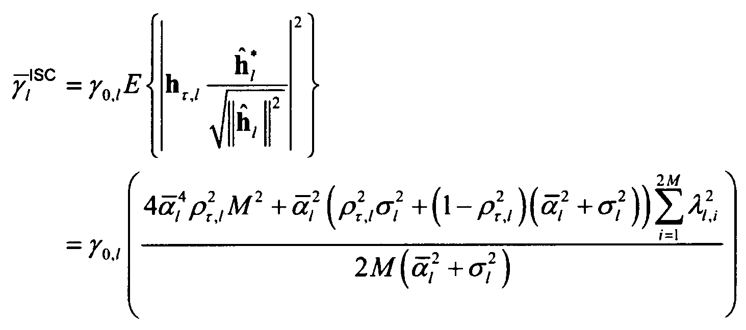
수학식 8
[규칙 제26조에 의한 보정 09.08.2011]
여기서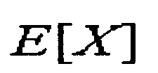 는 랜덤 변수 X의 기대값이며
 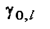 은 사용자 단말
  의 평균 SINR 값을 나타낸다.
여기서
[규칙 제26조에 의한 보정 09.08.2011]
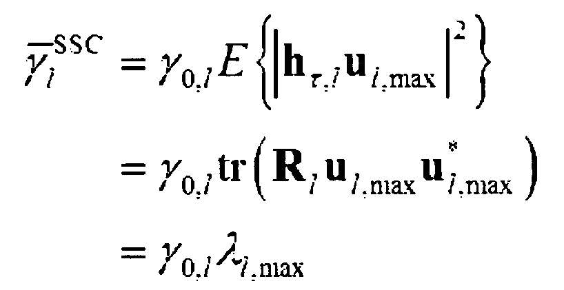
반면 사용자 단말 이 SSC 모드로 동작할 때 최대로 얻을 수 있는 SINR의 기대 값
 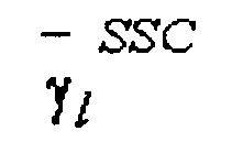 은 하기 <수학식 9>와 같다.
반면 사용자 단말
[규칙 제26조에 의한 보정 09.08.2011]
수학식 9 
수학식 9
여기서  는 송신 안테나 상관 행렬
  을 EVD 할 경우 나타나는 고유치값들 중 최대 고유치
  에 일치하는 고유 벡터를 나타내며 tr(A)는 행렬 A의 대각합 연산자(trace operator)를 나타낸다.
따라서, 상기 전송모드 결정기(201)는 다중의 사용자들이 ISC 모드 또는 SSC 모드로 동작할 때 얻을 수 있는 최대 SINR의 기대 값을 기준으로 <수학식 10>과 같이 각 사용자의 전송모드를 결정한다.
수학식 10 
즉, 상기 전송모드 결정기(201)는  과
과  를 비교하여 사용자 단말
  의 전송모드을 결정한다.
한편, 기지국은 사용자들의 속도, 사운딩 오차 및 송신안테나 공간 상관도를 고려하여 동종 모드 뿐만 아니라, 이종 모드 사용자들을 동시에 서비스할 수 있는 다중의 송신 빔을 결정한다. 다중 사용자를 동시에 서비스할 경우, 각 사용자가 얻을 수 있는 빔포밍 이득은 최대화하면서도 다중 빔으로 인해 유발될 수 있는 빔 간 간섭은 최소화되도록 다중 송신 빔을 결정하는 것이 중요하다. 따라서 본 발명은 사용자 단말 의 송신 빔
  을 통해 사용자 단말
  이 얻을 수 있는 빔포밍 이득은 최대화하면서도
  이 유발하는 다중 사용자 간섭량은 최소화되도록
  을 결정한다. 각 사용자들의 전송모드와 관계없이 L명의 사용자를 동시에 서비스하고, 이 중
  는 SSC 모드 사용자의 수,
  는 ISC 모드 사용자의 수,
  을 동시에 서비스되는 명의 다른 사용자들에게 유발하는 총 간섭량이라 가정하자. 서술의 편의를 위해 사용자 1부터
  는 ISC 모드 사용자, 사용자
  부터 L은 SSC 모드 사용자라고 가정할 때,
  은 하기 <수학식 11>과 같이 나타낼 수 있다.
수학식 11 
이때 ISC 사용자  의 송신 빔
  은
은  로 인한 순시 빔포밍 이득
  과 상기 <수학식 11>의 및 채널 잡음 값을 고려하여 하기 <수학식 12>와 같이 구할 수 있다.
수학식 12 
여기서  는 잡음 전력 밀도(noise power spectral densoty),
  은 2M×2M 단위행렬(Identity matrix)을 나타내며
  는 행렬 A의 최대 고유값에 대응하는 고유벡터를 나타낸다. 반면 SSC 사용자
  의 송신 빔
  은
은  로 인한 평균 빔포밍 이득
  과 하기 <수학식 11>의 을 고려하여 하기 <수학식 13>과 같이 구할 수 있다.
수학식 13 
즉, 상기 가중치 결정기(202)는 상기 전송모드 결정기(201)에 의해 결정된 사용자 단말의 전송모드를 기반으로, 셀 경계에 있는 모든 단말에 대해 상기 <수학식 12> 및 상기 <수학식 13>을 이용하여 다중의 송신 빔을 결정한다. 그리고, 상기 가중치 결정기(202)는 하기 <수학식 16>의 사용자 조합  에 대한 다중의 송신 빔을 하기 <수학식 12> 및 하기 <수학식 13>과 같이 결정하여, 그 결과를 상기 RF 전처리(207)로 제공한다.
본 발명은 각 사용자가 얻을 수 있는 빔포밍 이득과 다중 사용자 간섭량을 고려하여 상기 <수학식 12> 또는 상기 <수학식 13>과 같이 빔포밍 가중치를 결정하며, 특히 SSC 사용자의 경우 평균 채널 정보  을 활용하여 빔포밍 가중치를 결정하므로 사용자 속도 및 사운딩 오차로 인한 채널 불일치 문제에 상당히 강인하다.
상기 RF 전처리기(207)는 상기 가중치 결정기(202)로부터 최적 스케줄링 사용자 조합( )에 일치하는 다중 송신빔을 통해 데이터 신호를 전송한다.
상기 스케줄러(203)는 전송모드와 가중치가 결정된 사용자 단말들에 대해, 사용자 단말을 스케줄링하여 그 결과를 상기 시스템 용량 계산기(204)로 제공한다.
즉, 임의의 스케줄링 시간에 명의 사용자들 중 명의 사용자를 선택할 수 있는 조합의 수는 이며, 여기서
 이고
이고  을 나타낸다. 따라서 각 사용자들의 전송 모드와 관계없이 K명의 사용자들 중 시스템 채널 용량을 최대화하는
  명의 사용자 수와 사용자 조합을 선택하는 경우의 수는 총
  개이며, 이러한 사용자의 조합을 원소로 가지는 집합이다.
상기 시스템 용량 계산기(204)에서는 이를 바탕으로 상기 다중 송신 빔을 적용할 경우에 스케줄링 사용자 조합( )과 스케줄링 사용자 수(L)에 따른 시스템 채널 용량을 <수학식 14>과 같이 계산하고 이를 상기 시스템 용량 비교기(204)에 전달한다.
수학식 14 
여기서  은
은  내
내  번째 ISC 모드 사용자의 인덱스(index)를 나타내며,
  는
는  내 k번째 SSC 모드 사용자의 인덱스를 나타낸다.
L명의 사용자를 동시에 서비스할 때, ISC 모드 사용자  의 SINR 값은 하기 <수학식 15>와 같이 나타낼 수 있다.
수학식 15 
여기서 tr(A)는 행렬 A의 대각합 연산자(trace operator)를 나타낸다. 반면 L명의 사용자를 동시에 서비스할 때, SSC 모드 사용자  이 얻을 수 있는 SINR의 기대 값은 <수학식 16>와 같이 나타낼 수 있다.
수학식 16 
여기서  은 벡터
은 벡터  와
와  간의 각도 차이를 나타낸다. 본 발명은 이 같은 분석 결과를 바탕으로 다중 섹터 협력 빔포밍을 수행할 최적의 사용자 수와 사용자 조합을 결정한다. 기지국에서는 <수학식 14>와 <수학식 15>를 이용해 K명의 사용자 중 시스템 채널 용량을 최대화하는 사용자 수 L과 사용자 조합을 선택한다.
상기 시스템 용량 비교기(205)는 스케줄링 사용자 조합과 스케줄링 사용자 수에 따른 시스템 채널 용량을 비교하여 그 결과를 상기 사용자 조합 결정기(206)로 제공한다.
상기 사용자 조합 결정기(206)는 이를 이용해 <수학식 17>과 같이 시스템 채널 용량을 최대화하는 스케줄링 사용자 조합( )과 스케줄링 사용자 수를 결정한다. 여기서, 시스템 용량을 최대화하는 사용자 조합
  은 하기 <수학식 17>과 같이 표현될 수 있다.
수학식 17 
상술한 바와 같이, 본 발명은 상기 <수학식 14>과 상기 <수학식 17>을 통해 시스템 채널 용량을 최대화하는 사용자 수 및 사용자 조합  을 결정하고 속도 및 송신 안테나 공간 상관도가 상이한 사용자들을 동시에 지원할 수 있는 다중의 송신 빔을 통해 신호를 전송함으로써 속도 및 송신 안테나 공간 상관도가 상이한 사용자들을 지원함과 동시에 전체 시스템 용량의 성능을 높일 수 있다.
도 3은 본 발명의 실시 예에 따른 다중안테나 시스템에서 다중 섹터 협력 전송을 위한 기지국 동작 흐름도를 도시하고 있다.
상기 도 3을 참조하면, 기지국은 300단계에서 단말로부터 사운딩 신호를 수신하고, 302단계에서 사운딩 오차, 전송시간 지연, 송신안테나 공간 상관도를 결정한다.
이후, 상기 기지국은 304단계에서 빔포밍 모드에 따른 신호대잡음비를 결정한다. 즉, 상기 기지국은 사용자 단말  이 ISC 모드로 동작할 때 최대로 얻을 수 있는 SINR의 기대 값
  과 사용자 단말
  이 SSC 모드로 동작할 때 최대로 얻을 수 있는 SINR의 기대 값
  을 결정한다(<수학식 8>, <수학식 9> 참조).
이후, 상기 기지국은 306단계에서 빔포밍 모드에 따른 신호대잡음비를 기반으로, 사용자별 빔포밍 모드를 결정한다. 예를 들어,  이
이  보다 크면 사용자 단말
  을 ISC 모드로 결정하고,
  이
이  보다 작으면 사용자 단말
  을 SSC 모드로 결정한다.
이후, 상기 기지국은 308단계에서 빔포밍 모드가 결정된 사용자 단말들에 대해, 다중 사용자를 동시에 서비스할 경우, 각 사용자가 얻을 수 있는 빔포밍 이득은 최대화하면서도 다중 빔으로 인해 유발될 수 있는 빔 간 간섭은 최소화되도록 가중치를 결정한다.
이후, 상기 기지국은 310단계에서 L명의 사용자를 동시에 서비스할 때, ISC 모드 사용자  의 SINR 값, L명의 사용자를 동시에 서비스할 때, SSC 모드 사용자
  의 SINR 값을 기반으로, 시스템 채널 용량을 최대화하는 사용자 수 및 사용자 조합
  을 결정한다(상기 <수학식 14>과 상기 <수학식 17> 참조).
이후, 상기 기지국은 312단계에서 최적 스케줄링 사용자 조합( )에 일치하는 다중 송신빔을 통해 데이터 신호를 전송한다.
도 4는 본 발명의 실시 예에 따른 다중안테나 시스템에서 다중 섹터 협력 전송을 위한 단말 동작 흐름도를 도시하고 있다.
상기 도 4를 참조하면, 단말은 400단계에서 사운딩 신호를 서빙 기지국(혹은 서빙 섹터 및 인접 섹터들)으로 전송하고, 402단계에서 사운딩 오차, 전송 시간 지연, 송신안테나 공간 상관도를 고려한 빔포밍 모드의 하향링크 데이터를 수신한다.
이후, 상기 단말은 404단계에서 상기 하향링크 데이터를 디코딩한다.
도 5는 본 발명의 실시 예에 따른 송신 안테나 공간상관도 크기에 따른 전송 모드 별 성능을 나타내는 그래프이다.
상기 도 5를 참조하면, 모드 별 성능 분석 결과에 따른 각 전송 모드들의 교차 지점과 모드 별 실험 결과에 따른 각 전송 모드들의 교차 지점이 거의 일치하는 것을 확인할 수 있다. 분석 결과 및 실제 실험 결과 모두 송신 안테나의 공간 상관도의 크기가 약 0.3 이상일 경우, 평균 채널 섹터 협력 모드로 전송하는 것이 순시 채널 섹터 협력 모드로 전송할 때보다 성능이 우수한 것을 알 수 있다.
도 6은 본 발명의 실시 예에 따른 사용자 속도에 따른 전송 모드 별 성능을 나타내는 그래프이다.
상기 도 6을 참조하면, 상기 도 3과 마찬가지로 모드 별 성능 분석 결과에 따른 각 전송 모드들의 교차 지점과 모드 별 실험 결과에 따른 각 전송 모드들의 교차 지점이 거의 일치하는 것을 확인할 수 있다. 분석 결과 및 실제 실험 결과 모두 사용자의 속도가 약 35 km/h 이상일 경우, 평균 채널 섹터 협력 모드로 전송하는 것이 순시 채널 섹터 협력 모드로 전송할 때보다 성능이 우수한 것을 알 수 있다.
도 7을 본 발명의 실시 예에 따른 사용자 수 K에 따른 제안 기법의 성능을 나타내는 그래프이다.
상기 도 7을 참조하면, 본 발명의 성능이 순시 채널 정보만을 활용하는 MMSE 기반 섹터 협력 빔포밍 기법에 비해 우수함을 알 수 있다. 이는 본 발명이 각 사용자들의 전송모드 및 궤환 채널 정보를 바탕으로 ISC 및 SSC 모드 사용자들을 동시에 지원할 수 있는 다중 섹터 협력 송신 빔을 형성하고, 이를 통해 ISC 및 SSC 사용자의 구분없이 다중 섹터 협력 빔포밍을 수행할 최적의 사용자 수와 사용자 조합을 결정함으로써 전체 시스템 용량을 향상시킬 수 있기 때문이다. 그러나 MMSE 기반 섹터 협력 빔포밍 기법은 순시 채널 정보를 기반으로 하기 때문에 사용자의 속도 및 사운딩 오차로 인한 채널 불일치 문제에 상당히 취약하며, 채널 불일치 문제로 인한 성능 저하를 고려하지 않고 다중 사용자 스케줄링을 수행할 경우 시스템 용량이 최대화되는 최적 사용자 수 및 사용자 조합을 선택할 수 없기 때문에 다중 섹터 협력 전송 성능이 상당히 저하된다.
한편 본 발명의 상세한 설명에서는 구체적인 실시 예에 관해 설명하였으나, 본 발명의 범위에서 벗어나지 않는 한도 내에서 여러 가지 변형이 가능함은 물론이다. 그러므로 본 발명의 범위는 설명된 실시 예에 국한되어 정해져서는 아니 되며 후술하는 특허청구의 범위뿐만 아니라 이 특허청구의 범위와 균등한 것들에 의해 정해져야 한다.
Claims (15)
- 다중안테나 시스템에서 다중 섹터 협력 전송을 위한 송신 빔포밍 방법에 있어서,채널 환경에 따라 섹터 경계 사용자들의 전송모드를 결정하는 과정과,상기 사용자의 전송모드를 기반으로, 다중 사용자들을 지원할 수 있는 다중 섹터 협력 송신 빔을 결정하는 과정과,상기 결정된 다중 섹터 협력 송신 빔을 고려하여, 다중 섹터 협력 빔포밍을 위한 사용자 조합을 결정하는 과정과,상기 결정된 사용자 조합으로, 섹터 협력 송신 빔포밍을 수행하는 과정을 포함하는 것을 특징으로 하는 방법.
- 제 1항에 있어서,상기 채널 환경에 따라 섹터 경계 사용자들의 전송모드를 결정하는 과정은,상기 사용자가 제1 전송모드로 동작할 때의 제1 최대 신호대간섭잡음비(Signal-to-Interference plus Noise Ratio: SINR)를 결정하고, 상기 사용자가 제2 전송모드로 동작할 때의 제2 최대 SINR를 결정하는 과정과,상기 제1 최대 SINR과 상기 제2 최대 SINR를 비교하여 전송모드를 결정하는 과정을 포함하며,상기 제1 최대 SINR이 상기 제2 최대 SINR보다 크면, 상기 제1 전송모드를 선택하고, 상기 제1 최대 SINR이 상기 제2 최대 SINR보다 작으면, 상기 제2 전송모드를 선택하는 것을 특징으로 하는 방법.
- 제 2항에 있어서,제1 전송모드는 순시 채널 섹터 협력(Instantaneous channel Sector Cooperation: ISC) 모드이고, 제2 전송모드는 평균 채널 섹터 협력(Statistic channel Sector Cooperation: 이하 SSC) 모드인 것을 특징으로 하는 방법.
- 제 2항에 있어서,상기 제1 최대 SINR과 상기 제2 최대 SINR은 사운딩 오차, 전송 시간 지연 및 송신 안테나 공간 상관도 중 적어도 하나 이상이 고려되어 결정되는 것을 특징으로 하는 방법.
- [규칙 제26조에 의한 보정 09.08.2011]
제 2항에 있어서, 상기 제1 최대 SINR과 상기 제2 최대 SINR 은 하기 수학식으로 추정되는 것을 특징으로 하는 방법.
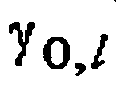
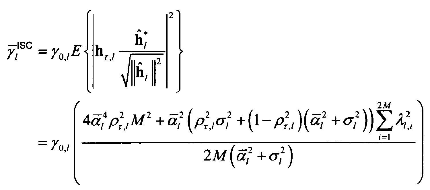 여기서, M은 섹터당 송신안테나 개수이고,
 는 랜덤 변수 X의 기대 값이며,
 은 사용자 단말
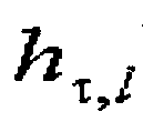
 의 평균 SINR 값을 나타내고,
 는 기지국과 사용자 단말
 사이의 채널추정벡터이고,
 는 행렬 A의 복소 전치 행렬(Hermitian matrix)이고,
 는 사운딩 오차
 , 전송 시간 지연 및 송신 안테나 공간 상관도
 가 고려된 사용자 단말
 의 지연 채널 벡터이고,
 은 섹터 협력을 수행하는 인접한 두 섹터와 사용자 사이 채널 경로 감쇠 값들의 평균 값이고, 상기
 는 섹터
는 섹터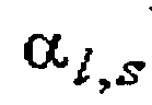 와 사용자 단말
 사이의 채널 경로감쇠(path loss)이고, M은 송신 안테나 수,
 은 사용자 단말
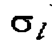 의 사운딩 채널추정 평균자승오차(Mean Squared Error: 이하 MSE),
 은 전송 지연 시간 로 인한 사용자 단말
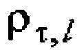 의 채널 벡터
 와 지연 채널 벡터
 간 시간 상관 계수이고,
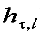 는 송신 안테나 상관 행렬
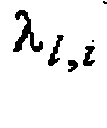 을 고유치 분해(Eigen-Value Decomposition: 이하 EVD) 했을 때 나타나는 고유치 값이다. 여기서
 는 송신 안테나 상관 행렬
 을 EVD 할 경우 나타나는 고유치값들 중 최대 고유치
 에 일치하는 고유 벡터를 나타내며 tr(A)는 행렬 A의 대각합 연산자(trace operator)를 나타냄.
- 제 5항에 있어서,상기는 k차 베셀 함수(Bessel function)를 이용하여 하기 수학식으로 정의되는 것을 특징으로 하는 방법.

 여기서는 전송 반송파 주파수(carrier frequency),
 은 사용자 속도를 나타내며
 는 빛의 속도( 3×108= m/s)임.
- 제 1항에 있어서,상기 사용자의 전송모드를 기반으로, 다중 사용자들을 지원할 수 있는 다중 섹터 협력 송신 빔을 결정하는 과정은,상기 다중 사용자가 얻을 수 있는 빔포밍 이득은 최대화하면서도 다중 빔으로 인해 유발될 수 있는 빔 간 간섭은 최소화되도록 제1 전송모드 및 제2 전송모드 사용자의 송신 빔을 결정하는 것을 특징으로 하는 방법.
- 제 7항에 있어서,상기 제1 전송모드 및 상기 제2 전송모드 사용자의 송신 빔은 하기 수학식으로 결정하는 것을 특징으로 하는 방법.

 여기서 No는 잡음 전력 밀도(noise power spectral densoty), L은 동시에 서비스되는 사용자 수, NISC는 L명의 사용자 중 동시에 서비스되는 제1 전송모드 사용자, I2M은 단위행렬(Identity matrix)을 나타내며,는 행렬 A의 최대 고유값에 대응하는 고유벡터,
 과 송신 안테나 채널 상관 행렬임.
- 제 8항에 있어서,상기은 하기 수학식으로 정의되는 것을 특징으로 하는 방법.

 이때,는 행렬 A의 복소 전치 행렬(Hermitian matrix)을 나타내고,
 는 의 기대 값임.
- 제 1항에 있어서,상기 결정된 다중 섹터 협력 송신 빔을 고려하여, 다중 섹터 협력 빔포밍을 위한 사용자 조합을 결정하는 과정은,상기 다중 섹터 협력 송신 빔포밍을 수행할 모든 스케줄링 사용자 조합과 스케줄링 사용자 수에 따른 시스템 채널 용량을 계산하는 과정과,상기 계산된 시스템 채널 용량을 비교하는 과정과,상기 비교 결과로부터, 상기 시스템 채널 용량을 최대화하는 최적 스케줄링 사용자 조합과 스케줄링 사용자 수를 결정하는 과정을 포함하는 것을 특징으로 하는 방법.
- 제 10항에 있어서,상기 시스템 채널 용량을 계산 과정은,가 K명의 사용자들 중 선택 가능한 모든 스케줄링 사용자 수와 사용자 조합을 나타내는 집합에서,
 을 집합 G의 n번째 원소라 할 때,
 에 따른 시스템 채널 용량은 하기 수학식으로 결정되는 것을 특징으로 하는 방법.
 여기서은
여기서은 내
내 번째 ISC 모드 사용자의 인덱스(index)를 나타내며,
 는
는 내 k번째 SSC 모드 사용자의 인덱스를 나타내고,
 는 L명의 사용자를 동시에 서비스할 때, 제1 전송모드 사용자
 의 SINR 값이고,
 는 L명의 사용자를 동시에 서비스할 때, 제2 전송모드 사용자
 이 얻을 수 있는 SINR임.

 여기서, tr(A)는 행렬 A의 대각합 연산자(trace operator)를 나타내고,은 벡터
 와
와 간의 각도 차이를 나타냄.
- 제 10항에 있어서,상기 시스템 채널 용량을 최대화하는 최적 스케줄링 사용자 조합과 스케줄링 사용자 수를 결정하는 과정은,다중 섹터 협력 전송 시스템 채널 용량을 최대화하는 사용자 수과 사용자 조합(
 )을 하기 수학식과 같이 결정하는 것을 특징으로 하는 방법.

- 다중안테나 시스템에서 다중 섹터 협력 전송을 위한 송신 빔포밍 장치에 있어서,채널 환경에 따라 섹터 경계 사용자들의 전송모드를 결정하는 전송모드 결정기와,상기 사용자의 전송모드를 기반으로, 다중 사용자들을 지원할 수 있는 다중 섹터 협력 송신 빔을 결정하는 가중치 결정기와,상기 결정된 다중 섹터 협력 송신 빔을 고려하여, 다중 섹터 협력 빔포밍을 위한 사용자 조합을 결정하는 사용자 조합 결정기와,상기 결정된 사용자 조합으로, 섹터 협력 송신 빔포밍을 수행하는 RF 전처리기를 포함하는 것을 특징으로 하는 장치.
- 제 13항에 있어서,상기 전송모드 결정기는,상기 사용자가 제1 전송모드로 동작할 때의 제1 최대 신호대간섭잡음비(Signal-to-Interference plus Noise Ratio: SINR)를 결정하고, 상기 사용자가 제2 전송모드로 동작할 때의 제2 최대 SINR를 결정하고,상기 제1 최대 SINR과 상기 제2 최대 SINR를 비교하여 전송모드를 결정하며,제1 전송모드는 순시 채널 섹터 협력(Instantaneous channel Sector Cooperation: ISC) 모드이고, 제2 전송모드는 평균 채널 섹터 협력(Statistic channel Sector Cooperation: 이하 SSC) 모드이고,상기 제1 최대 SINR과 상기 제2 최대 SINR은 사운딩 오차, 전송 시간 지연 및 송신 안테나 공간 상관도 중 적어도 하나 이상이 고려되어 결정되는 것을 특징으로 하는 장치.
- 제 13항에 있어서,상기 사용자 조합 결정기는,상기 다중 섹터 협력 송신 빔포밍을 수행할 모든 스케줄링 사용자 조합과 스케줄링 사용자 수에 따른 시스템 채널 용량을 계산하는 계산기와,상기 계산된 시스템 채널 용량을 비교하는 비교기와,상기 비교 결과로부터, 상기 시스템 채널 용량을 최대화하는 최적 스케줄링 사용자 조합과 스케줄링 사용자 수를 결정하는 스케줄러를 포함하는 것을 특징으로 하는 장치.
Priority Applications (1)
| Application Number | Priority Date | Filing Date | Title |
|---|---|---|---|
| US13/813,138 US8929244B2 (en) | 2010-07-29 | 2011-07-29 | Method and device for send beamforming and multiple user scheduling for multiple sector cooperative transmission in a multiple antenna system |
Applications Claiming Priority (2)
| Application Number | Priority Date | Filing Date | Title |
|---|---|---|---|
| KR1020100073236A KR101761821B1 (ko) | 2010-07-29 | 2010-07-29 | 다중안테나 시스템에서 다중 섹터 협력 전송을 위한 송신 빔포밍과 다중 사용자 스케줄링 방법 및 장치 |
| KR10-2010-0073236 | 2010-07-29 |
Publications (2)
| Publication Number | Publication Date |
|---|---|
| WO2012015279A2 true WO2012015279A2 (ko) | 2012-02-02 |
| WO2012015279A3 WO2012015279A3 (ko) | 2012-04-19 |
Family
ID=45530636
Family Applications (1)
| Application Number | Title | Priority Date | Filing Date |
|---|---|---|---|
| PCT/KR2011/005629 Ceased WO2012015279A2 (ko) | 2010-07-29 | 2011-07-29 | 다중안테나 시스템에서 다중 섹터 협력 전송을 위한 송신 빔포밍과 다중 사용자 스케줄링 방법 및 장치 |
Country Status (3)
| Country | Link |
|---|---|
| US (1) | US8929244B2 (ko) |
| KR (1) | KR101761821B1 (ko) |
| WO (1) | WO2012015279A2 (ko) |
Families Citing this family (8)
| Publication number | Priority date | Publication date | Assignee | Title |
|---|---|---|---|---|
| GB2517218B (en) | 2013-08-16 | 2017-10-04 | Analog Devices Global | Communication unit and method of antenna array calibration |
| GB2517217B (en) * | 2013-08-16 | 2018-03-21 | Analog Devices Global | Communication unit, integrated circuit and method for generating a plurality of sectored beams |
| KR102077109B1 (ko) * | 2014-02-05 | 2020-02-13 | 에스케이텔레콤 주식회사 | 기지국장치 및 기지국장치의 동작 방법 |
| CN105471790B (zh) * | 2014-08-04 | 2020-05-15 | 北京三星通信技术研究有限公司 | 适用于分布式天线系统的协作传输方法、基站及终端 |
| KR101616636B1 (ko) | 2014-10-16 | 2016-04-28 | 영남대학교 산학협력단 | 듀얼 모드 빔포밍 방법 및 장치 |
| US9787373B1 (en) * | 2016-06-29 | 2017-10-10 | Facebook, Inc. | Hybrid node |
| EP4738960A2 (en) * | 2018-04-10 | 2026-05-06 | Fraunhofer-Gesellschaft zur Förderung der angewandten Forschung e.V. | Communication devices, communication coordinating devices, and communication methods |
| KR102193882B1 (ko) * | 2018-12-18 | 2020-12-23 | 중앙대학교 산학협력단 | 무선 전력 충전정보 전송 방법 및 그 방법을 수행하는 공유기 |
Family Cites Families (14)
| Publication number | Priority date | Publication date | Assignee | Title |
|---|---|---|---|---|
| AU2001226986A1 (en) * | 2000-01-18 | 2001-07-31 | Nortel Networks Limited | Multi-beam antenna system for high speed data |
| US6751206B1 (en) * | 2000-06-29 | 2004-06-15 | Qualcomm Incorporated | Method and apparatus for beam switching in a wireless communication system |
| US8670390B2 (en) * | 2000-11-22 | 2014-03-11 | Genghiscomm Holdings, LLC | Cooperative beam-forming in wireless networks |
| US7136655B2 (en) * | 2002-11-21 | 2006-11-14 | Bandspeed, Inc. | Method and apparatus for coverage and throughput enhancement in a wireless communication system |
| US7239879B2 (en) * | 2003-11-26 | 2007-07-03 | Lucent Technologies Inc. | Opportunistic beamforming and scheduling of users in a communication system |
| CN101185200B (zh) * | 2005-11-14 | 2011-07-20 | 桥扬科技有限公司 | 用于蜂窝通信和广播的多天线系统 |
| US7746827B2 (en) * | 2007-03-30 | 2010-06-29 | Intel Corporation | Methods and arrangements for selection of a wireless transmission method based upon signal to noise ratios |
| EP2232637B1 (en) * | 2007-12-19 | 2017-05-03 | Telecom Italia S.p.A. | Method and system for switched beam antenna communications |
| US8406171B2 (en) | 2008-08-01 | 2013-03-26 | Texas Instruments Incorporated | Network MIMO reporting, control signaling and transmission |
| CN101651880B (zh) * | 2008-08-11 | 2013-12-25 | 株式会社Ntt都科摩 | 多小区协作发送方法 |
| US8315657B2 (en) | 2008-09-22 | 2012-11-20 | Futurewei Technologies, Inc. | System and method for enabling coordinated beam switching and scheduling |
| US8923125B2 (en) * | 2008-10-24 | 2014-12-30 | Qualcomm Incorporated | Wireless network resource adaptation |
| JP5450638B2 (ja) * | 2008-10-30 | 2014-03-26 | アルカテル−ルーセント | マルチセクタ協調通信における協調タイプの切り替え技術 |
| US20100177726A1 (en) | 2009-01-12 | 2010-07-15 | Kim Olszewski | Method and system for synchronization and cell identification within communication systems |
-
2010
- 2010-07-29 KR KR1020100073236A patent/KR101761821B1/ko not_active Expired - Fee Related
-
2011
- 2011-07-29 US US13/813,138 patent/US8929244B2/en active Active
- 2011-07-29 WO PCT/KR2011/005629 patent/WO2012015279A2/ko not_active Ceased
Also Published As
| Publication number | Publication date |
|---|---|
| WO2012015279A3 (ko) | 2012-04-19 |
| US8929244B2 (en) | 2015-01-06 |
| US20130128764A1 (en) | 2013-05-23 |
| KR101761821B1 (ko) | 2017-07-27 |
| KR20120011952A (ko) | 2012-02-09 |
Similar Documents
| Publication | Publication Date | Title |
|---|---|---|
| WO2012015279A2 (ko) | 다중안테나 시스템에서 다중 섹터 협력 전송을 위한 송신 빔포밍과 다중 사용자 스케줄링 방법 및 장치 | |
| Wang et al. | Uplink performance of cell-free massive MIMO over spatially correlated Rician fading channels | |
| WO2022035278A1 (en) | Method and apparatus for measurement and reporting for multi-beam operations | |
| WO2020067740A1 (en) | Method and apparatus for channel state information estimation | |
| KR100559070B1 (ko) | 적응형 안테나 어레이 및 그 제어 방법 | |
| WO2018174630A1 (en) | A method and device for transmitting data | |
| WO2015020464A1 (en) | Method and apparatus for transmitting and receiving feedback information in mobile communication system based on 2 dimensional massive mimo | |
| WO2015178711A1 (en) | Channel state information feedback method and apparatus for 2-dimensional massive mimo communication system | |
| WO2012021008A2 (en) | Method and apparatus for transmitting and receiving reference signal in wireless communication system | |
| WO2014204267A1 (en) | Method and device for energy efficient signal transmission in massive multi-antenna wireless communication system | |
| WO2013032294A2 (en) | Multiple antenna transmission with per-antenna power constraints | |
| WO2021141432A1 (en) | Method and apparatus of parameter tracking for csi estimation | |
| WO2010044522A2 (en) | Apparatus and method for transmission of dynamic feedback channel information in a mimo system | |
| WO2014109538A1 (ko) | 무선 통신 시스템에서 셀 간 간섭 제거 방법 및 장치 | |
| WO2024039135A1 (en) | Method and apparatus for transmission mode adaptation in wireless communication system | |
| WO2012074306A2 (ko) | 주파수 도약 확산 시스템의 간섭 신호 회피 장치 및 그 방법 | |
| WO2021256882A1 (en) | Method and apparatus for performing uplink power control and uplink channel transmission | |
| WO2023177240A1 (en) | Method and apparatus for an srs procedure | |
| WO2023075513A1 (en) | Method and apparatus for interference management | |
| EP4490853A1 (en) | Systems and methods for basis-based compression of doppler coefficients for csi feedback | |
| WO2010074523A2 (ko) | 빔포밍을 위한 가중치 행렬 결정 방법 및 장치 | |
| WO2025263851A1 (en) | Node and terminal in wireless communication system and method performed by the same | |
| WO2022124778A1 (en) | Method and apparatus for transmission of uplink control information in wireless communication system | |
| WO2014061995A1 (ko) | 이동통신 시스템에서 사용자 단말 선택 방법 및 장치 | |
| WO2023249177A1 (ko) | Mu-miso 시스템을 위한 것으로서 채널 오류에 강인한 wmmse 빔포밍 매트릭스 설계 방법 및 장치 |
Legal Events
| Date | Code | Title | Description |
|---|---|---|---|
| 121 | Ep: the epo has been informed by wipo that ep was designated in this application |
Ref document number: 11812808 Country of ref document: EP Kind code of ref document: A2 |
|
| NENP | Non-entry into the national phase |
Ref country code: DE |
|
| WWE | Wipo information: entry into national phase |
Ref document number: 13813138 Country of ref document: US |
|
| 122 | Ep: pct application non-entry in european phase |
Ref document number: 11812808 Country of ref document: EP Kind code of ref document: A2 |