WO2012008015A1 - 溶解性物質濃縮システムおよび溶解性物質濃縮システムの運用方法 - Google Patents
溶解性物質濃縮システムおよび溶解性物質濃縮システムの運用方法 Download PDFInfo
- Publication number
- WO2012008015A1 WO2012008015A1 PCT/JP2010/061805 JP2010061805W WO2012008015A1 WO 2012008015 A1 WO2012008015 A1 WO 2012008015A1 JP 2010061805 W JP2010061805 W JP 2010061805W WO 2012008015 A1 WO2012008015 A1 WO 2012008015A1
- Authority
- WO
- WIPO (PCT)
- Prior art keywords
- steam
- heat recovery
- exhaust heat
- recovery boiler
- soluble substance
- Prior art date
- Legal status (The legal status is an assumption and is not a legal conclusion. Google has not performed a legal analysis and makes no representation as to the accuracy of the status listed.)
- Ceased
Links
Images

Classifications
-
- C—CHEMISTRY; METALLURGY
- C02—TREATMENT OF WATER, WASTE WATER, SEWAGE, OR SLUDGE
- C02F—TREATMENT OF WATER, WASTE WATER, SEWAGE, OR SLUDGE
- C02F1/00—Treatment of water, waste water, or sewage
- C02F1/02—Treatment of water, waste water, or sewage by heating
- C02F1/04—Treatment of water, waste water, or sewage by heating by distillation or evaporation
- C02F1/16—Treatment of water, waste water, or sewage by heating by distillation or evaporation using waste heat from other processes
-
- B—PERFORMING OPERATIONS; TRANSPORTING
- B01—PHYSICAL OR CHEMICAL PROCESSES OR APPARATUS IN GENERAL
- B01D—SEPARATION
- B01D1/00—Evaporating
- B01D1/0011—Heating features
- B01D1/0058—Use of waste energy from other processes or sources, e.g. combustion gas
-
- C—CHEMISTRY; METALLURGY
- C02—TREATMENT OF WATER, WASTE WATER, SEWAGE, OR SLUDGE
- C02F—TREATMENT OF WATER, WASTE WATER, SEWAGE, OR SLUDGE
- C02F1/00—Treatment of water, waste water, or sewage
- C02F1/02—Treatment of water, waste water, or sewage by heating
- C02F1/04—Treatment of water, waste water, or sewage by heating by distillation or evaporation
- C02F1/048—Purification of waste water by evaporation
-
- C—CHEMISTRY; METALLURGY
- C02—TREATMENT OF WATER, WASTE WATER, SEWAGE, OR SLUDGE
- C02F—TREATMENT OF WATER, WASTE WATER, SEWAGE, OR SLUDGE
- C02F1/00—Treatment of water, waste water, or sewage
- C02F1/44—Treatment of water, waste water, or sewage by dialysis, osmosis or reverse osmosis
- C02F1/441—Treatment of water, waste water, or sewage by dialysis, osmosis or reverse osmosis by reverse osmosis
-
- C—CHEMISTRY; METALLURGY
- C02—TREATMENT OF WATER, WASTE WATER, SEWAGE, OR SLUDGE
- C02F—TREATMENT OF WATER, WASTE WATER, SEWAGE, OR SLUDGE
- C02F2103/00—Nature of the water, waste water, sewage or sludge to be treated
- C02F2103/08—Seawater, e.g. for desalination
-
- C—CHEMISTRY; METALLURGY
- C02—TREATMENT OF WATER, WASTE WATER, SEWAGE, OR SLUDGE
- C02F—TREATMENT OF WATER, WASTE WATER, SEWAGE, OR SLUDGE
- C02F2103/00—Nature of the water, waste water, sewage or sludge to be treated
- C02F2103/10—Nature of the water, waste water, sewage or sludge to be treated from quarries or from mining activities
-
- Y—GENERAL TAGGING OF NEW TECHNOLOGICAL DEVELOPMENTS; GENERAL TAGGING OF CROSS-SECTIONAL TECHNOLOGIES SPANNING OVER SEVERAL SECTIONS OF THE IPC; TECHNICAL SUBJECTS COVERED BY FORMER USPC CROSS-REFERENCE ART COLLECTIONS [XRACs] AND DIGESTS
- Y02—TECHNOLOGIES OR APPLICATIONS FOR MITIGATION OR ADAPTATION AGAINST CLIMATE CHANGE
- Y02A—TECHNOLOGIES FOR ADAPTATION TO CLIMATE CHANGE
- Y02A20/00—Water conservation; Efficient water supply; Efficient water use
- Y02A20/124—Water desalination
-
- Y—GENERAL TAGGING OF NEW TECHNOLOGICAL DEVELOPMENTS; GENERAL TAGGING OF CROSS-SECTIONAL TECHNOLOGIES SPANNING OVER SEVERAL SECTIONS OF THE IPC; TECHNICAL SUBJECTS COVERED BY FORMER USPC CROSS-REFERENCE ART COLLECTIONS [XRACs] AND DIGESTS
- Y02—TECHNOLOGIES OR APPLICATIONS FOR MITIGATION OR ADAPTATION AGAINST CLIMATE CHANGE
- Y02P—CLIMATE CHANGE MITIGATION TECHNOLOGIES IN THE PRODUCTION OR PROCESSING OF GOODS
- Y02P70/00—Climate change mitigation technologies in the production process for final industrial or consumer products
- Y02P70/10—Greenhouse gas [GHG] capture, material saving, heat recovery or other energy efficient measures, e.g. motor control, characterised by manufacturing processes, e.g. for rolling metal or metal working
Definitions
- the present invention relates to a system for concentrating soluble substances by evaporation, such as desalination of brackish water and seawater, and concentration of accompanying water generated when coal bed methane gas is obtained.
- the present invention relates to a system including an evaporative concentration facility using steam generated by utilizing exhaust heat.
- Coal bed methane gas is obtained by pumping the accompanying water contained in the coal bed with a screw pump installed in the well and separating the dissolved methane gas in the accompanying water. At this time, it is necessary to treat the accompanying water after the methane gas separation.
- accompanying water contains salts (sodium salt, calcium salt, silica, etc.), so there was a problem with irrigation water, use for greening, and draining into untreated rivers.
- the accompanying water is separated into concentrated water and fresh water, and the reduced concentrated water is sent to the reservoir. There is a way to dispose.
- the accompanying water is first separated into concentrated water and fresh water using a reverse osmosis membrane type concentrator, and the concentrated water is further separated into highly concentrated water and fresh water using an evaporative concentrator, thereby further reducing the volume of the accompanying water to be discarded.
- the reverse osmosis membrane type concentrator has a problem that the operating cost increases when the concentration of a soluble substance such as salts increases.
- the application of the evaporation method is advantageous in terms of cost.
- the evaporation method requires steam, it is desirable to install it together with the power generation equipment and use the exhaust heat of the power generation equipment.
- the vapor generated by making effective use of the exhaust heat from the power generation equipment is supplied to the evaporative concentration equipment.
- Kiyoshi Ishida Basic knowledge of IWPP for workers of oil upstream companies, Japan Petroleum Natural Gas and Metals Mineral Resources Organization (JOGMEC), Web page URL: http://oilgas-info.jogmec.go.jp/pdf/ 2/2110 / 200809_009a.pdf
- an imbalance may occur between the supply amount of steam generated by effectively using the exhaust heat of the power generation equipment and the steam demand of the evaporative concentration equipment.
- the electric power produced by the power generation equipment is used for power sales or other equipment.
- the power demand can be fluctuated from the second or minute order to the day or month order.
- the power generation facilities are operated with less waste, such as partial load operation, the heat energy of the exhaust heat varies from the second or minute order to the day or month order.
- the power generation efficiency also depends on the atmospheric temperature of the intake air, the heat energy of exhaust heat also varies depending on the atmospheric temperature. As a result, the supply amount of steam generated by effectively using the exhaust heat of the power generation equipment also varies.
- the power generation equipment since the power generation equipment has many moving parts such as rotating motion, it is necessary to periodically stop and perform maintenance. During the period when the power generation facility is stopped, exhaust heat cannot be obtained and steam is not supplied.
- the steam demand of the evaporative concentration equipment varies depending on the temporal fluctuation of the accompanying water intake.
- the steam demand of the evaporative concentrator varies depending on the temporal fluctuation of freshwater demand.
- the present invention provides a gas turbine power generator, an exhaust heat recovery boiler that generates steam using hot gas having exhaust heat from the gas turbine power generator, and the exhaust heat recovery boiler.
- a soluble substance concentration system comprising an evaporation type concentrating device for concentrating raw water containing a soluble substance using the steam supplied from as a heat source, steam supply assistance for further assisting the supply of steam to the evaporation type concentrating device Means.
- the gas turbine power generator outputs electric power and exhausts the gas turbine power generator exhaust gas.
- the gas turbine power generator exhaust gas is supplied to the exhaust heat recovery boiler as a hot gas.
- the exhaust heat recovery boiler generates steam, and the generated steam is given to the evaporative concentrator.
- the evaporative concentrator concentrates raw water using this steam as a heat source.
- the steam supply auxiliary means operates to assist the supply of steam to the evaporative concentrator. Thereby, the processing capacity of the evaporative concentration apparatus can be maintained.
- the steam supply auxiliary means has an auxiliary burner for supplying hot gas to the exhaust heat recovery boiler.
- the steam supply auxiliary means includes a second boiler that is provided separately from the exhaust heat recovery boiler and supplies steam to the evaporative concentrator.
- the steam supply auxiliary means generates a steam by a diesel generator capable of rapid start-up and a hot gas having exhaust heat from the diesel generator, and the evaporative concentration And a waste heat recovery boiler for a diesel generator for supplying steam to the apparatus.
- the present invention is an operation method of a soluble substance concentration system including a gas turbine power generation device, an exhaust heat recovery boiler, an evaporation type concentration device, and a steam supply auxiliary device.
- the evaporative concentrator In the evaporative concentrator, a concentration step of concentrating raw water containing a soluble substance with the steam generated in the steam generation step, a determination step of determining a shortage of steam supply in the concentration step, and the determination step,
- the steam supply auxiliary device includes an auxiliary supply step of supplementarily supplying steam to the evaporative concentrator.
- a method for operating a soluble substance concentration system comprising a gas turbine power generator, an exhaust heat recovery boiler, an evaporative concentrator, and a steam supply auxiliary device, A gas turbine power generator operates, the exhaust heat recovery boiler generates steam by a hot gas having exhaust heat from the gas turbine power generation apparatus, and the evaporative concentrator is supplied from the exhaust heat recovery boiler.
- a normal step of concentrating the raw water containing the soluble substance by the steam a determination step of determining an operation state of the gas turbine power generation device in the normal step, and determining that the gas turbine power generation device is inoperative in the determination step
- the vapor supply auxiliary device supplies the vapor to the evaporative concentrator
- the evaporative concentrator includes the auxiliary supply step.
- a soluble substance concentration system including a gas turbine power generation device and an evaporative concentration device
- the steam supply assisting means assists the supply of steam to the evaporative concentrator, so that the processing capacity of the evaporative concentrator can be maintained, and the accompanying water treatment, seawater desalination treatment, seawater desalination concentrated water is maintained. It is possible to concentrate soluble substances such as evaporation to dryness.
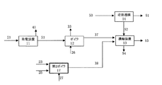
- FIG. 1 is a block diagram of a soluble substance concentration system according to a first embodiment.
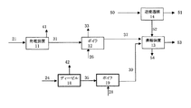
- FIG. It is a block diagram of the soluble substance concentration system which concerns on 2nd Embodiment. It is a block diagram of the soluble substance concentration system which concerns on 3rd Embodiment.
- FIG. 1 is a block diagram of the soluble substance concentration system according to the first embodiment.
- the soluble substance concentration system includes, as a basic configuration, a gas turbine power generation device 11, an exhaust heat recovery boiler 12 that generates steam using hot gas having exhaust heat from the gas turbine power generation device 11, and the exhaust heat recovery boiler 12. And an evaporative concentrating device 13 for concentrating raw water containing a soluble substance using the steam supplied from as a heat source, and an auxiliary burner 16 as a characteristic configuration.
- the auxiliary burner 16 is provided between the gas turbine power generator 11 and the exhaust heat recovery boiler 12.
- the gas turbine power generator 11 is provided with a fuel 21 mainly composed of hydrocarbons.
- the gas turbine power generator 11 burns the fuel 21 and drives the generator to output electric power 41 and discharge the gas turbine power generator exhaust gas 31.
- the gas turbine power generator exhaust gas 31 has thermal energy and also has oxygen necessary for combustion.
- the auxiliary burner 16 does not operate during normal operation.
- the gas turbine power generator exhaust gas 31 passes through the auxiliary burner 16 and is given to the exhaust heat recovery boiler 12 as a hot gas 31.
- Water 26 is further given to the exhaust heat recovery boiler 12.
- the exhaust heat recovery boiler 12 generates steam 37 by the heat energy of the hot gas 31 and the water 26.
- the hot gas 31 is discarded as exhaust heat recovery boiler exhaust gas 33 after giving thermal energy to the steam 37.
- the generated steam 37 is given to the evaporative concentrator 13.
- raw water 50 (associated water, seawater, seawater desalinated concentrated water, etc.) is separated into fresh water 51 and concentrated water 52 by the reverse osmosis membrane concentrator 14.
- the fresh water 51 is discharged into a river or reused as irrigation water.
- the concentrated water 52 is supplied to the evaporative concentration device 13.
- the concentrated water 52 concentrated by the reverse osmosis membrane type concentrator 14 is supplied to the evaporative concentrator 13, but the raw water 50 may be directly supplied to the evaporative concentrator 13.
- the evaporative concentrator 13 concentrates the concentrated water 52 (or raw water 50) using the supplied steam 37 as a heat source.
- the concentrated water 52 (or raw water 50) is separated into fresh water 53 and highly concentrated water 54.
- Fresh water 53 is discharged into rivers or reused as irrigation water.
- the highly concentrated water 54 is discharged to a storage facility or completely evaporated to dryness and crystallized.
- the processing capacity of the evaporative concentrator 13 decreases. Therefore, the supply amount and demand amount of the steam 37 are always detected. If it is determined that the steam supply amount is insufficient, the auxiliary burner 16 operates.
- the auxiliary burner 16 uses the gas turbine power generator exhaust gas 31 as combustion air, burns the additional fuel 22 and repels it, and outputs a hot gas 32.
- the hot gas 32 is given to the exhaust heat recovery boiler 12.
- the heat energy of the hot gas 32 is larger than the heat energy of the hot gas 31 before the operation of the auxiliary burner 16 by the amount burned by the auxiliary burner 16, and as a result, the steam from the exhaust heat recovery boiler 12. Supply will increase.
- the evaporative concentration device 13 cannot be processed. Therefore, the operation status of the gas turbine power generator 11 is always detected. When it is determined that the gas turbine power generator 11 is not operating, the auxiliary burner 16 is operated.
- the auxiliary burner 16 burns the additional fuel 22 to catch up, and outputs a hot gas 32.
- the hot gas 32 is given to the exhaust heat recovery boiler 12.
- the exhaust heat recovery boiler 12 supplies the vapor 37 to the evaporative concentrator 13 so as to satisfy the vapor demand of the evaporative concentrator 13.
- FIG. 2 is a block diagram of the soluble substance concentration system according to the second embodiment.
- the soluble substance concentration system includes, as a basic configuration, a gas turbine power generation device 11, an exhaust heat recovery boiler 12 that generates steam using hot gas having exhaust heat from the gas turbine power generation device 11, and the exhaust heat recovery boiler 12. And an evaporation type concentrating device 13 for concentrating raw water containing a soluble substance using the steam supplied from as a heat source, and a second boiler 17 as a characteristic configuration.
- the second boiler 17 is provided separately from the exhaust heat recovery boiler 12.
- the gas turbine power generator 11 is provided with a fuel 21 mainly composed of hydrocarbons.
- the gas turbine power generator 11 burns the fuel 21 and drives the generator to output electric power 41 and discharge the gas turbine power generator exhaust gas 31.
- the gas turbine power generator exhaust gas 31 has thermal energy and also has oxygen necessary for combustion.
- the gas turbine power generator exhaust gas 31 is given to the exhaust heat recovery boiler 12 as a hot gas 31.
- Water 26 is further given to the exhaust heat recovery boiler 12.
- the exhaust heat recovery boiler 12 generates steam 37 by the heat energy of the hot gas 31 and the water 26.
- the hot gas 31 is discarded as exhaust heat recovery boiler exhaust gas 33 after giving thermal energy to the steam 37.
- the generated steam 37 is given to the evaporative concentrator 12.
- raw water 50 (associated water, seawater, seawater desalinated concentrated water, etc.) is separated into fresh water 51 and concentrated water 52 by the reverse osmosis membrane concentrator 14.
- Fresh water 52 is discharged into rivers or reused as irrigation water.
- the concentrated water 52 is supplied to the evaporative concentration device 13.
- the concentrated water 52 concentrated by the reverse osmosis membrane type concentrator 14 is supplied to the evaporative concentrator 13, but the raw water 50 may be directly supplied to the evaporative concentrator 13.
- the evaporative concentrator 13 concentrates the concentrated water 52 (or raw water 50) using the supplied steam 37 as a heat source.
- the concentrated water 52 (or raw water 50) is separated into fresh water 53 and highly concentrated water 54.
- Fresh water 53 is discharged into rivers or reused as irrigation water.
- the highly concentrated water 54 is discharged to a storage facility or completely evaporated to dryness and crystallized.
- the processing capacity of the evaporative concentrator 13 decreases. Therefore, the supply amount and demand amount of the steam 37 are always detected. If it is determined that the steam supply amount is insufficient, the second boiler 17 operates.
- the second boiler 17 is given water 27, fuel 23, and air 25.
- the second boiler 17 generates steam 38 by the heat energy obtained by burning the fuel 23 and the water 27.
- the fuel 23 and the air 25 are discarded as boiler exhaust gas 34 after giving thermal energy to the steam 38.
- the generated vapor 38 is given to the evaporative concentrator 24.
- the steam 37 from the exhaust heat recovery boiler 12 and the steam 38 from the second boiler 17 are supplied to the evaporative concentrator 13, and the steam supply amount increases by the amount of the steam 37.
- the second boiler 17 is given water 27, fuel 23, and air 25.
- the second boiler 17 generates steam 38 by the heat energy obtained by burning the fuel 23 and the water 27.
- the generated vapor 38 is given to the evaporative concentrator 13.
- the second boiler 17 supplies the vapor 38 to the evaporative concentrator 13 so as to satisfy the vapor demand of the evaporative concentrator 13.
- FIG. 3 is a block diagram of the soluble substance concentration system according to the third embodiment.
- the soluble substance concentration system includes, as a basic configuration, a gas turbine power generation device 11, an exhaust heat recovery boiler 12 that generates steam using hot gas having exhaust heat from the gas turbine power generation device 11, and the exhaust heat recovery boiler 12. And an evaporation type concentrating device 13 for concentrating raw water containing a soluble substance using the steam supplied from as a heat source. Further, as a characteristic configuration, a diesel generator 18 and an exhaust heat recovery boiler 19 for a diesel generator are provided. Prepare.
- the diesel generator 18 and the exhaust heat recovery boiler 19 for the diesel generator are provided separately from the exhaust heat recovery boiler 12.
- the gas turbine power generator 11 is provided with a fuel 21 mainly composed of hydrocarbons.
- the gas turbine power generator 11 burns the fuel 21 and drives the generator to output electric power 41 and discharge the gas turbine power generator exhaust gas 31.
- the gas turbine power generator exhaust gas 31 has thermal energy and also has oxygen necessary for combustion.
- the gas turbine power generator exhaust gas 31 and the hot gas 31 are given to the exhaust heat recovery boiler 12.
- Water 26 is further given to the exhaust heat recovery boiler 12.
- the exhaust heat recovery boiler 12 generates steam 37 by the heat energy of the hot gas 31 and the water 26.
- the hot gas 31 is discarded as exhaust heat recovery boiler exhaust gas 33 after giving thermal energy to the steam 37.
- the generated steam 37 is given to the evaporative concentrator 11.
- raw water 50 (associated water, seawater, seawater desalinated concentrated water, etc.) is separated into fresh water 51 and concentrated water 52 by the reverse osmosis membrane concentrator 14.
- the fresh water 51 is discharged into a river or reused as irrigation water.
- the concentrated water 52 is supplied to the evaporative concentration device 13.
- the concentrated water 52 concentrated by the reverse osmosis membrane type concentrator 14 is supplied to the evaporative concentrator 13, but the raw water 50 may be directly supplied to the evaporative concentrator 13.
- the evaporative concentrator 13 concentrates the concentrated water 52 (or raw water 50) using the supplied steam 37 as a heat source.
- the concentrated water 52 (or raw water 50) is separated into fresh water 53 and highly concentrated water 54.
- Fresh water 53 is discharged into rivers or reused as irrigation water.
- the highly concentrated water 54 is discharged to a storage facility or completely evaporated to dryness and crystallized.
- the processing capacity of the evaporative concentrator 13 decreases. Therefore, the supply amount and demand amount of the steam 37 are always detected. If it is determined that the steam supply amount is insufficient, the diesel generator 18 and the diesel generator exhaust heat recovery boiler 19 operate.
- Fuel 24 is given to the diesel generator 18.
- the diesel generator 18 burns the fuel 24 and drives the generator to output electric power 42 and discharge the diesel generator exhaust gas 35.
- the diesel generator 18 can be started quickly and can respond quickly.
- the diesel power generator exhaust gas 35 has thermal energy and also has oxygen necessary for combustion.
- the gas turbine power generator exhaust gas 35 is provided as a hot gas 35 to the exhaust heat recovery boiler 19 for a diesel generator.
- water 28 is given to the exhaust heat recovery boiler 19 for the diesel generator.
- the diesel generator exhaust heat recovery boiler 19 generates steam 39 by the thermal energy of the hot gas 35 and the water 28.
- the hot gas 35 gives heat energy to the steam 39 and is then discarded as exhaust heat recovery boiler exhaust gas 36 for a diesel generator.
- the generated steam 39 is given to the evaporative concentrator 13.
- the steam 37 from the exhaust heat recovery boiler 12 and the steam 39 from the diesel generator exhaust heat recovery boiler 19 are supplied to the evaporative concentrator 11, and the steam supply amount increases by the amount of the steam 39.
- the processing capacity of the evaporative concentrator 13 can be maintained by the operation of the diesel generator 18 and the exhaust heat recovery boiler 19 for the diesel generator.
- the diesel generator exhaust heat recovery boiler 19 is supplied with water 28 and hot gas 35 from the diesel generator 18.
- the diesel generator exhaust heat recovery boiler 19 generates steam 39 by the thermal energy of the hot gas 35 and the water 28.
- the generated steam 39 is given to the evaporative concentrator 13.
- the exhaust heat recovery boiler 19 for the diesel generator supplies the steam 39 to the evaporative concentrator 13 so as to satisfy the steam demand of the evaporative concentrator 13.
- the processing capacity of the evaporative concentrator 13 can be maintained by the operation of the diesel generator 18 and the exhaust heat recovery boiler 19 for the diesel generator.
Landscapes
- Engineering & Computer Science (AREA)
- Environmental & Geological Engineering (AREA)
- Water Supply & Treatment (AREA)
- Chemical & Material Sciences (AREA)
- Life Sciences & Earth Sciences (AREA)
- Hydrology & Water Resources (AREA)
- Organic Chemistry (AREA)
- Chemical Kinetics & Catalysis (AREA)
- Heat Treatment Of Water, Waste Water Or Sewage (AREA)
- Separation Using Semi-Permeable Membranes (AREA)
Abstract
電力需要が低下して蒸気供給が不足する場合または発電設備が停止して蒸気供給が停止する場合においても、蒸発式濃縮装置の処理能力を維持する。 通常時、ガスタービン発電装置11は、電力41を出力するとともに、ガスタービン発電装置排ガス31を排出する。ガスタービン発電装置排ガス31は補助バーナ40を通過し、熱気体31として排熱回収ボイラ12に与えられる。排熱回収ボイラ12は、蒸気37を発生させ、発生した蒸気37は蒸発式濃縮装置11に与えられる。 蒸気供給量が不足していると判断されると、補助バーナ16が動作する。補助バーナ16は、ガスタービン発電装置排ガス31を燃焼空気として用い、追加燃料22を燃焼させて追い焚きをして熱気体32を出力する。熱気体32は排熱回収ボイラ12に与えられる。その結果、排熱回収ボイラ12からの蒸気供給量は増加する。
Description
本発明は、かん水や海水の淡水化処理や、炭層メタンガスを得る際に発生する随伴水の濃縮処理など、溶解性物質を蒸発法によって濃縮するシステムに関し、特に、発電設備とこの発電設備からの排熱を利用して発生する蒸気を用いる蒸発式濃縮設備とを備えたシステムに関する。
近年、新たな天然ガス源として炭層メタンガスが注目されている。炭層メタンガスは炭層に含まれる随伴水を井戸に設置したスクリューポンプで汲み上げ、随伴水中に溶解しているメタンガスを分離して得られる。この際に、メタンガス分離後の随伴水の処理が必要となる。通常、随伴水には塩類(ナトリウム塩、カルシウム塩、シリカなど)が含まれているため、灌漑用水や緑化への使用や未処理状態での河川への排水には問題があった。
そこで、MSF(多段フラッシュ法)やMED(多重効用蒸発器)などの蒸発法による蒸発式濃縮設備を用いて、随伴水を濃縮水と淡水に分離し、減容化された濃縮水をため池へ廃棄する方法がある。また、随伴水をまず逆浸透膜式濃縮装置で濃縮水と淡水に分離し、その濃縮水をさらに蒸発式濃縮設備によって高濃縮水と淡水に分離することで、廃棄する随伴水をさらに減容化する方法がある。逆浸透膜式濃縮装置は、塩類など溶解性物質の濃度が高くなると運転コストが増大するという問題がある。そのため、塩類など溶解性物質が含まれている随伴水を高濃度まで濃縮化する場合には、蒸発法の適用がコスト的に有利である。ただし、蒸発法では蒸気が必要となるため、発電設備と共に設置して発電設備の排熱を利用することが望ましい。蒸発式濃縮設備には発電設備の排熱を有効利用して発生した蒸気が供給される。
また、世界的に淡水の水資源不足が問題となりつつある。この対応策としてかん水や海水の淡水化処理が注目されている。淡水化処理とは、かん水や海水に含まれる塩類(例えば塩化ナトリウム)、すなわち溶解性物質を濃縮し、その一方で淡水を得るものである。この淡水化処理でも、電力と淡水の供給事業(IWPP)においては発電設備の排熱が有効利用できる点から、非特許文献1で示すように蒸発法が有利となる場合がある。
海水淡水化処理の場合、塩類が濃縮された濃縮排水の水環境に及ぼす影響が蒸発法、逆浸透膜法のいずれでも問題になりつつある。濃縮排水を完全に蒸発乾固し溶解性物質を結晶化することで、水環境に及ぼす影響は低減することが可能となる。ここで、蒸発乾固するためには熱エネルギーが必要であり、その熱エネルギーを供給する手段として発電設備の排熱を利用することが有用である。蒸発式濃縮設備には発電設備の排熱を有効利用して発生した蒸気が供給される。
以上のように、発電設備と蒸発式濃縮設備を同時に備えた溶解性物質濃縮システムが今後増加すると見込まれる。
石田聖、石油上流企業従事者のためのIWPP基礎知識、(独)石油天然ガス・金属鉱物資源機構(JOGMEC)、Webページ URL:http://oilgas-info.jogmec.go.jp/pdf/2/2110/200809_009a.pdf
しかし、下記のように、発電設備の排熱を有効利用して発生する蒸気の供給量と、蒸発式濃縮設備の蒸気需要量の間にアンバランスが発生する可能性がある。
発電設備で造られた電力は売電あるいは他の設備の動力として用いられるのが一般的である。その場合、電力需要は秒や分オーダーから日、月オーダーで変動することが考えられる。発電設備は部分負荷運転をするなど無駄を省く運転を実施するため、排熱の熱エネルギーも秒や分オーダーから日、月オーダーで変動することになる。また、発電効率は吸気の大気温度にも依存するため、排熱の熱エネルギーも大気温度に依存して変動することになる。その結果、発電設備の排熱を有効利用して発生する蒸気の供給量も変動する。
また、発電設備は回転運動等の可動部分が多いため、定期的に停止してメンテナンスをする必要がある。発電設備が停止している期間には排熱を得られず、蒸気が供給されなくなる。
一方、随伴水処理の場合、蒸発式濃縮設備の蒸気需要量は随伴水取水量の時間的変動に依存して変動する。海水淡水化処理や海水淡水化濃縮水の蒸発乾固の場合、蒸発式濃縮設備の蒸気需要量は淡水需要量の時間的変動に依存して変動する。
このように、従来の発電設備と蒸発式濃縮設備とを備えた溶解性物質濃縮システムにおいては、蒸気需給のアンバランスに係る課題があった。特に、蒸気供給が不足する場合、蒸発式濃縮設備の処理能力が低下する。さらに、発電設備が停止し蒸気供給がなくなると、蒸発式濃縮設備は処理不能となる。
本発明の目的は、発電設備と蒸発式濃縮設備とを備えた溶解性物質濃縮システムにおいて、電力需要が低下して蒸気供給が不足する場合または発電設備が停止して蒸気供給がない場合においても、蒸発式濃縮設備の処理能力を維持できる溶解性物質濃縮システムおよびその運用方法を提供することにある。
(1)上記目的を達成するために、本発明は、ガスタービン発電装置と、このガスタービン発電装置からの排熱を有する熱気体により蒸気を発生させる排熱回収ボイラと、この排熱回収ボイラから供給された蒸気を熱源として溶解性物質を含む原水を濃縮する蒸発式濃縮装置とを備えた溶解性物質濃縮システムにおいて、更に、前記蒸発式濃縮装置への蒸気の供給を補助する蒸気供給補助手段を備える。
本発明においては、ガスタービン発電装置は、電力を出力するとともに、ガスタービン発電装置排ガスを排出する。ガスタービン発電装置排ガスは熱気体として排熱回収ボイラに与えられる。排熱回収ボイラは、蒸気を発生させ、発生した蒸気は蒸発式濃縮装置に与えられる。蒸発式濃縮装置は、この蒸気を熱源として原水を濃縮する。
通常時、排熱回収ボイラからの蒸気供給量と蒸発式濃縮装置の蒸気需要量との間でバランスが取れている。
蒸気供給不足時または蒸気供給停止時には、蒸気供給補助手段が動作し、蒸発式濃縮装置への蒸気の供給を補助する。これにより、蒸発式濃縮装置の処理能力を維持することができる。
(2)上記(1)において、好ましくは、前記蒸気供給補助手段は、前記排熱回収ボイラに熱気体を供給する補助バーナを有する。
(3)上記(1)において、好ましくは、前記蒸気供給補助手段は、前記排熱回収ボイラと別途設けられ、前記蒸発式濃縮装置へ蒸気を供給する第2ボイラを有する。
(4)上記(1)において、好ましくは、前記蒸気供給補助手段は、急速起動可能なディーゼル発電機と、このディーゼル発電機からの排熱を有する熱気体により蒸気を発生させ、前記蒸発式濃縮装置へ蒸気を供給するディーゼル発電機用排熱回収ボイラとを有する。
(5)上記目的を達成するために、本発明は、ガスタービン発電装置と、排熱回収ボイラと、蒸発式濃縮装置と、蒸気供給補助装置とを備えた溶解性物質濃縮システムの運用方法であって、前記ガスタービン発電装置が動作する発電装置動作ステップと、前記排熱回収ボイラが、前記発電装置動作ステップで発生する排熱を有する熱気体により、蒸気を発生する蒸気発生ステップと、前記蒸発式濃縮装置が、前記蒸気発生ステップで生じた蒸気により、溶解性物質を含む原水を濃縮する濃縮ステップと、前記濃縮ステップにおける蒸気供給量の不足を判断する判断ステップと、前記判断ステップにおいて、蒸気供給量が不足と判断された場合、前記蒸気供給補助装置が、前記蒸発式濃縮装置に蒸気を補助的に供給する補助供給ステップとを有する。
これにより、電力需要低下等により蒸気供給が不足する場合でも、蒸気供給補助装置が動作し、蒸発式濃縮装置の処理能力を維持することができる。
(5)上記目的を達成するために、ガスタービン発電装置と、排熱回収ボイラと、蒸発式濃縮装置と、蒸気供給補助装置とを備えた溶解性物質濃縮システムの運用方法であって、前記ガスタービン発電装置が動作し、前記排熱回収ボイラが、このガスタービン発電装置からの排熱を有する熱気体により、蒸気を発生し、前記蒸発式濃縮装置が、この排熱回収ボイラから供給された蒸気により、溶解性物質を含む原水を濃縮する通常ステップと、前記通常ステップにおける前記ガスタービン発電装置の動作状況を判断する判断ステップと、前記判断ステップで前記ガスタービン発電装置が不動作と判断された場合、前記蒸気供給補助装置が、前記蒸発式濃縮装置に蒸気を供給する補助供給ステップと、前記蒸発式濃縮装置が、前記補助供給ステップによる蒸気により、溶解性物質を含む原水を濃縮する濃縮ステップとを有する。
これにより、ガスタービン発電装置停止などにより蒸気供給が停止する場合でも、蒸気供給補助装置が動作し、蒸発式濃縮装置の処理能力を維持することができる。
本発明によれば、ガスタービン発電装置と蒸発式濃縮装置とを備えた溶解性物質濃縮システムにおいて、電力需要が低下して蒸気供給が不足する場合またはガスタービン発電設備が停止し蒸気供給がない場合においても、蒸気供給補助手段が蒸発式濃縮装置への蒸気の供給を補助することにより、蒸発式濃縮装置の処理能力を維持でき、随伴水処理、海水淡水化処理、海水淡水化濃縮水の蒸発乾固など溶解性物質の濃縮処理が可能となる。
<第1実施形態>
以下、本発明の第1実施形態を図面を参照しつつ説明する。
以下、本発明の第1実施形態を図面を参照しつつ説明する。
図1は、第1実施形態に係る溶解性物質濃縮システムのブロック線図である。溶解性物質濃縮システムは、基本構成として、ガスタービン発電装置11と、このガスタービン発電装置11からの排熱を有する熱気体により蒸気を発生させる排熱回収ボイラ12と、この排熱回収ボイラ12から供給された蒸気を熱源として溶解性物質を含む原水を濃縮する蒸発式濃縮装置13とを備え、更に、特徴的構成として補助バーナ16を備える。
補助バーナ16は、ガスタービン発電装置11と排熱回収ボイラ12との間に設けられている。
通常時(蒸気の需給バランスが取れているとき)の溶解性物質濃縮システムの動作を説明する。
ガスタービン発電装置11には、炭化水素を主成分とする燃料21が与えられる。ガスタービン発電装置11は、この燃料21を燃焼させて発電機を駆動することで電力41を出力するとともに、ガスタービン発電装置排ガス31を排出する。ガスタービン発電装置排ガス31は熱エネルギーを有していると同時に、燃焼に必要な酸素も残有している。
通常時には補助バーナ16は動作しない。ガスタービン発電装置排ガス31は補助バーナ16を通過し、熱気体31として排熱回収ボイラ12に与えられる。
排熱回収ボイラ12には、更に水26が与えられる。排熱回収ボイラ12は、熱気体31の熱エネルギーと水26により蒸気37を発生させる。熱気体31は蒸気37に熱エネルギーを与えた後、排熱回収ボイラ排ガス33として廃棄される。発生した蒸気37は蒸発式濃縮装置13に与えられる。
一方、原水50(随伴水、海水、海水淡水化濃縮水など)は、逆浸透膜式濃縮装置14により淡水51と濃縮水52に分離される。淡水51は河川に放流されたり、灌漑用水として再利用される。濃縮水52は、蒸発式濃縮装置13に供給される。なお、本実施形態では、逆浸透膜式濃縮装置14により濃縮された濃縮水52が蒸発式濃縮装置13に供給されたが、原水50が蒸発式濃縮装置13に直接供給されてもよい。
蒸発式濃縮装置13は、供給された蒸気37を熱源として濃縮水52(または原水50)を濃縮する。濃縮水52(または原水50)は、淡水53と高濃縮水54に分離される。淡水53は河川に放流されたり、灌漑用水として再利用される。高濃縮水54は、貯留設備に排出されるか、完全に蒸発乾固し結晶化される。
蒸気供給不足時の溶解性物質濃縮システムの動作を説明する。
電力需要低下等により蒸気37の供給が不足すると、蒸発式濃縮装置13の処理能力が低下する。そのため、蒸気37の供給量と需要量は常時検出されている。蒸気供給量が不足していると判断されると、補助バーナ16が動作する。
補助バーナ16は、ガスタービン発電装置排ガス31を燃焼空気として用い、追加燃料22を燃焼させて追い焚きをして熱気体32を出力する。熱気体32は排熱回収ボイラ12に与えられる。
このときの熱気体32の熱エネルギーは、補助バーナ16動作前の熱気体31の熱エネルギーに比べて、補助バーナ16で追い焚きされた分だけ大きく、その結果、排熱回収ボイラ12からの蒸気供給量は増加する。
これにより、蒸気供給不足時であっても、補助バーナ16の動作により、蒸発式濃縮装置13の処理能力を維持できる。
蒸気供給停止時の溶解性物質濃縮システムの動作を説明する。
ガスタービン発電装置11停止などにより蒸気37の供給が停止すると、蒸発式濃縮装置13は処理不能となる。そのため、ガスタービン発電装置11の動作状況は常時検出されている。ガスタービン発電装置11が動作していないと判断されると、補助バーナ16が動作する。
補助バーナ16は、追加燃料22を燃焼させて追い焚きをして熱気体32を出力する。熱気体32は排熱回収ボイラ12に与えられる。
このときの熱気体32は充分な熱エネルギーを有し、その結果、排熱回収ボイラ12は蒸発式濃縮装置13の蒸気需要を満たすように蒸気37を蒸発式濃縮装置13に供給する。
これにより、蒸気供給停止時であっても、補助バーナ16の動作により、蒸発式濃縮装置の処理能力を維持できる。
蒸気供給不足時また蒸気供給停止時であっても、蒸発式濃縮装置13の処理能力を維持することにより、随伴水処理、海水淡水化処理、海水淡水化濃縮水の蒸発乾固など溶解性物質の濃縮処理が可能となる。
<第2実施形態>
本発明の第2実施形態を図面を参照しつつ説明する。
本発明の第2実施形態を図面を参照しつつ説明する。
図2は、第2実施形態に係る溶解性物質濃縮システムのブロック線図である。溶解性物質濃縮システムは、基本構成として、ガスタービン発電装置11と、このガスタービン発電装置11からの排熱を有する熱気体により蒸気を発生させる排熱回収ボイラ12と、この排熱回収ボイラ12から供給された蒸気を熱源として溶解性物質を含む原水を濃縮する蒸発式濃縮装置13とを備え、更に、特徴的構成として第2ボイラ17を備える。
第2ボイラ17は、排熱回収ボイラ12とは別途併設されている。
通常時(蒸気の需給バランスが取れているとき)の溶解性物質濃縮システムの動作を説明する。
ガスタービン発電装置11には、炭化水素を主成分とする燃料21与えられる。ガスタービン発電装置11は、この燃料21を燃焼させて発電機を駆動することで電力41を出力するとともに、ガスタービン発電装置排ガス31を排出する。ガスタービン発電装置排ガス31は熱エネルギーを有していると同時に、燃焼に必要な酸素も残有している。ガスタービン発電装置排ガス31は、熱気体31として排熱回収ボイラ12に与えられる。
排熱回収ボイラ12には、更に水26が与えられる。排熱回収ボイラ12は、熱気体31の熱エネルギーと水26により蒸気37を発生させる。熱気体31は蒸気37に熱エネルギーを与えた後、排熱回収ボイラ排ガス33として廃棄される。発生した蒸気37は蒸発式濃縮装置12に与えられる。
一方、原水50(随伴水、海水、海水淡水化濃縮水など)は、逆浸透膜式濃縮装置14により淡水51と濃縮水52に分離される。淡水52は河川に放流されたり、灌漑用水として再利用される。濃縮水52は、蒸発式濃縮装置13に供給される。なお、本実施形態では、逆浸透膜式濃縮装置14により濃縮された濃縮水52が蒸発式濃縮装置13に供給されたが、原水50が蒸発式濃縮装置13に直接供給されてもよい。
蒸発式濃縮装置13は、供給された蒸気37を熱源として濃縮水52(または原水50)を濃縮する。濃縮水52(または原水50)は、淡水53と高濃縮水54に分離される。淡水53は河川に放流されたり、灌漑用水として再利用される。高濃縮水54は、貯留設備に排出されるか、完全に蒸発乾固し結晶化される。
蒸気供給不足時の溶解性物質濃縮システムの動作を説明する。
電力需要低下等により蒸気37の供給が不足すると、蒸発式濃縮装置13の処理能力が低下する。そのため、蒸気37の供給量と需要量は常時検出されている。蒸気供給量が不足していると判断されると、第2ボイラ17が動作する。
第2ボイラ17には、水27と燃料23と空気25が与えられる。第2ボイラ17は、燃料23を燃焼させた熱エネルギーと水27により蒸気38を発生させる。燃料23と空気25は蒸気38に熱エネルギーを与えた後、ボイラ排ガス34として廃棄される。発生した蒸気38は、蒸発式濃縮装置24に与えられる。
すなわち、蒸発式濃縮装置13には、排熱回収ボイラ12からの蒸気37と第2ボイラ17からの蒸気38が供給され、蒸気37の分だけ、蒸気供給量は増加する。
これにより、蒸気供給不足時であっても、第2ボイラ17の動作により、蒸発式濃縮装置13の処理能力を維持できる。
蒸気供給停止時の溶解性物質濃縮システムの動作を説明する。
ガスタービン発電装置11停止などにより蒸気37の供給が停止すると、蒸発式濃縮装置13は処理不能となる。そのため、ガスタービン発電装置11の動作状況は常時検出されている。ガスタービン発電装置11が動作していないと判断されると、排熱回収ボイラ12は停止し、第2ボイラ17が動作する。
第2ボイラ17には、水27と燃料23と空気25が与えられる。第2ボイラ17は、燃料23を燃焼させた熱エネルギーと水27により蒸気38を発生させる。発生した蒸気38は、蒸発式濃縮装置13に与えられる。
すなわち、第2ボイラ17は蒸発式濃縮装置13の蒸気需要を満たすように蒸気38を蒸発式濃縮装置13に供給する。
これにより、蒸気供給停止時であっても、第2ボイラ17の動作により、蒸発式濃縮装置13の処理能力を維持できる。
蒸気供給不足時また蒸気供給停止時であっても、蒸発式濃縮装置13の処理能力を維持することにより、随伴水処理、海水淡水化処理、海水淡水化濃縮水の蒸発乾固など溶解性物質の濃縮処理が可能となる。
<第3実施形態>
本発明の第3実施形態を図面を参照しつつ説明する。
本発明の第3実施形態を図面を参照しつつ説明する。
図3は、第3実施形態に係る溶解性物質濃縮システムのブロック線図である。溶解性物質濃縮システムは、基本構成として、ガスタービン発電装置11と、このガスタービン発電装置11からの排熱を有する熱気体により蒸気を発生させる排熱回収ボイラ12と、この排熱回収ボイラ12から供給された蒸気を熱源として溶解性物質を含む原水を濃縮する蒸発式濃縮装置13とを備え、更に、特徴的構成として、ディーゼル発電機18と、ディーゼル発電機用排熱回収ボイラ19とを備える。
ディーゼル発電機18およびディーゼル発電機用排熱回収ボイラ19は、排熱回収ボイラ12とは別途併設されている。
通常時(蒸気の需給バランスが取れているとき)の溶解性物質濃縮システムの動作を説明する。
ガスタービン発電装置11には、炭化水素を主成分とする燃料21が与えられる。ガスタービン発電装置11は、この燃料21を燃焼させて発電機を駆動することで電力41を出力するとともに、ガスタービン発電装置排ガス31を排出する。ガスタービン発電装置排ガス31は熱エネルギーを有していると同時に、燃焼に必要な酸素も残有している。ガスタービン発電装置排ガス31、熱気体31として排熱回収ボイラ12に与えられる。
排熱回収ボイラ12には、更に水26が与えられる。排熱回収ボイラ12は、熱気体31の熱エネルギーと水26により蒸気37を発生させる。熱気体31は蒸気37に熱エネルギーを与えた後、排熱回収ボイラ排ガス33として廃棄される。発生した蒸気37は蒸発式濃縮装置11に与えられる。
一方、原水50(随伴水、海水、海水淡水化濃縮水など)は、逆浸透膜式濃縮装置14により淡水51と濃縮水52に分離される。淡水51は河川に放流されたり、灌漑用水として再利用される。濃縮水52は、蒸発式濃縮装置13に供給される。なお、本実施形態では、逆浸透膜式濃縮装置14により濃縮された濃縮水52が蒸発式濃縮装置13に供給されたが、原水50が蒸発式濃縮装置13に直接供給されてもよい。
蒸発式濃縮装置13は、供給された蒸気37を熱源として濃縮水52(または原水50)を濃縮する。濃縮水52(または原水50)は、淡水53と高濃縮水54に分離される。淡水53は河川に放流されたり、灌漑用水として再利用される。高濃縮水54は、貯留設備に排出されるか、完全に蒸発乾固し結晶化される。
蒸気供給不足時の溶解性物質濃縮システムの動作を説明する。
電力需要低下等により蒸気37の供給が不足すると、蒸発式濃縮装置13の処理能力が低下する。そのため、蒸気37の供給量と需要量は常時検出されている。蒸気供給量が不足していると判断されると、ディーゼル発電機18およびディーゼル発電機用排熱回収ボイラ19が動作する。
ディーゼル発電機18には、燃料24が与えられる。ディーゼル発電機18は、この燃料24を燃焼させて発電機を駆動することで電力42を出力するとともに、ディーゼル発電装置排ガス35を排出する。ディーゼル発電機18は急速起動が可能であり、迅速な対応が可能である。ディーゼル発電装置排ガス35は熱エネルギーを有していると同時に、燃焼に必要な酸素も残有している。ガスタービン発電装置排ガス35は、熱気体35としてディーゼル発電機用排熱回収ボイラ19に与えられる。
ディーゼル発電機用排熱回収ボイラ19には、更に水28が与えられる。ディーゼル発電機用排熱回収ボイラ19は、熱気体35の熱エネルギーと水28により蒸気39を発生させる。熱気体35は蒸気39に熱エネルギーを与えた後、ディーゼル発電機用排熱回収ボイラ排ガス36として廃棄される。発生した蒸気39は蒸発式濃縮装置13に与えられる。
すなわち、蒸発式濃縮装置11には、排熱回収ボイラ12からの蒸気37とディーゼル発電機用排熱回収ボイラ19からの蒸気39が供給され、蒸気39の分だけ、蒸気供給量は増加する。
これにより、蒸気供給不足時であっても、ディーゼル発電機18およびディーゼル発電機用排熱回収ボイラ19の動作により、蒸発式濃縮装置13の処理能力を維持できる。
蒸気供給停止時の溶解性物質濃縮システムの動作を説明する。
ガスタービン発電装置11停止などにより蒸気37の供給が停止すると、蒸発式濃縮装置13は処理不能となる。そのため、ガスタービン発電装置11の動作状況は常時検出されている。ガスタービン発電装置11が動作していないと判断されると、排熱回収ボイラ12は停止し、ディーゼル発電機18およびディーゼル発電機用排熱回収ボイラ19が動作する。
ディーゼル発電機用排熱回収ボイラ19には、水28とディーゼル発電機18からの熱気体35が与えられる。ディーゼル発電機用排熱回収ボイラ19は、熱気体35の熱エネルギーと水28により蒸気39を発生させる。発生した蒸気39は、蒸発式濃縮装置13に与えられる。
すなわち、ディーゼル発電機用排熱回収ボイラ19は蒸発式濃縮装置13の蒸気需要を満たすように蒸気39を蒸発式濃縮装置13に供給する。
これにより、蒸気供給停止時であっても、ディーゼル発電機18およびディーゼル発電機用排熱回収ボイラ19の動作により、蒸発式濃縮装置13の処理能力を維持できる。
蒸気供給不足時また蒸気供給停止時であっても、蒸発式濃縮装置13の処理能力を維持することにより、随伴水処理、海水淡水化処理、海水淡水化濃縮水の蒸発乾固など溶解性物質の濃縮処理が可能となる。
11 ガスタービン発電装置
12 排熱回収ボイラ
13 蒸発式濃縮装置
14 逆浸透膜式濃縮装置
16 補助バーナ
17 第2ボイラ17
18 ディーゼル発電機
19 ディーゼル発電機用排熱回収ボイラ
21~24 燃料
25 空気
26~28 水
31~36 排ガス(熱気体)
37~39 蒸気
41~42 電力
50 原水
51,53 淡水
52 濃縮水
54 高濃縮水
12 排熱回収ボイラ
13 蒸発式濃縮装置
14 逆浸透膜式濃縮装置
16 補助バーナ
17 第2ボイラ17
18 ディーゼル発電機
19 ディーゼル発電機用排熱回収ボイラ
21~24 燃料
25 空気
26~28 水
31~36 排ガス(熱気体)
37~39 蒸気
41~42 電力
50 原水
51,53 淡水
52 濃縮水
54 高濃縮水
Claims (6)
- ガスタービン発電装置(11)と、このガスタービン発電装置からの排熱を有する熱気体(31)により蒸気を発生させる排熱回収ボイラ(12)と、この排熱回収ボイラから供給された蒸気(37)を熱源として溶解性物質を含む原水(50,52)を濃縮する蒸発式濃縮装置(13)とを備えた溶解性物質濃縮システムにおいて、
更に、前記蒸発式濃縮装置への蒸気の供給を補助する蒸気供給補助手段(16,17,18,19)を備えることを特徴とする溶解性物質濃縮システム。 - 請求項1記載の溶解性物質濃縮システムにおいて、
前記蒸気供給補助手段は、前記排熱回収ボイラ(12)に熱気体(32)を供給する補助バーナ(16)を有することを特徴とする溶解性物質濃縮システム。 - 請求項1記載の溶解性物質濃縮システムにおいて、
前記蒸気供給補助手段は、前記排熱回収ボイラ(12)と別途設けられ、前記蒸発式濃縮装置(13)へ蒸気(38)を供給する第2ボイラ(17)を有することを特徴とする溶解性物質濃縮システム。 - 請求項1記載の溶解性物質濃縮システムにおいて、
前記蒸気供給補助手段は、急速起動可能なディーゼル発電機(18)と、このディーゼル発電機からの排熱を有する熱気体(35)により蒸気を発生させ、前記蒸発式濃縮装置(13)へこの蒸気(39)を供給するディーゼル発電機用排熱回収ボイラ(19)とを有することを特徴とする溶解性物質濃縮システム。 - ガスタービン発電装置(11)と、排熱回収ボイラ(12)と、蒸発式濃縮装置(13)と、蒸気供給補助装置(16,17,18,19)とを備えた溶解性物質濃縮システムの運用方法であって、
前記ガスタービン発電装置(11)が動作する発電装置動作ステップと、
前記排熱回収ボイラ(12)が、前記発電装置動作ステップで発生する排熱を有する熱気体(31)により、蒸気を発生する蒸気発生ステップと、
前記蒸発式濃縮装置(13)が、前記蒸気発生ステップで生じた蒸気(37)により、溶解性物質を含む原水(50,52)を濃縮する濃縮ステップと、
前記濃縮ステップにおける蒸気供給量の不足を判断する判断ステップと、
前記判断ステップにおいて、蒸気供給量が不足と判断された場合、前記蒸気供給補助装置(16,17,18,19)が、前記蒸発式濃縮装置に蒸気を補助的に供給する補助供給ステップと
を有する溶解性物質濃縮システムの運用方法。 - ガスタービン発電装置(11)と、排熱回収ボイラ(12)と、蒸発式濃縮装置(13)と、蒸気供給補助装置(16,17,18,19)とを備えた溶解性物質濃縮システムの運用方法であって、
前記ガスタービン発電装置(11)が動作し、前記排熱回収ボイラ(12)が、このガスタービン発電装置からの排熱を有する熱気体(31)により、蒸気を発生し、前記蒸発式濃縮装置(13)が、この排熱回収ボイラから供給された蒸気(37)により、溶解性物質を含む原水(50,52)を濃縮する通常ステップと、
前記通常ステップにおける前記ガスタービン発電装置(11)の動作状況を判断する判断ステップと、
前記判断ステップで前記ガスタービン発電装置が不動作と判断された場合、前記蒸気供給補助装置(16,17,18,19)が、前記蒸発式濃縮装置に蒸気を供給する補助供給ステップと、
前記蒸発式濃縮装置(13)が、前記補助供給ステップによる蒸気により、溶解性物質を含む原水を濃縮する濃縮ステップと
を有する溶解性物質濃縮システムの運用方法。
Priority Applications (2)
| Application Number | Priority Date | Filing Date | Title |
|---|---|---|---|
| PCT/JP2010/061805 WO2012008015A1 (ja) | 2010-07-12 | 2010-07-12 | 溶解性物質濃縮システムおよび溶解性物質濃縮システムの運用方法 |
| JP2012524358A JP5495405B2 (ja) | 2010-07-12 | 2010-07-12 | 溶解性物質濃縮システムおよび溶解性物質濃縮システムの運用方法 |
Applications Claiming Priority (1)
| Application Number | Priority Date | Filing Date | Title |
|---|---|---|---|
| PCT/JP2010/061805 WO2012008015A1 (ja) | 2010-07-12 | 2010-07-12 | 溶解性物質濃縮システムおよび溶解性物質濃縮システムの運用方法 |
Publications (1)
| Publication Number | Publication Date |
|---|---|
| WO2012008015A1 true WO2012008015A1 (ja) | 2012-01-19 |
Family
ID=45469040
Family Applications (1)
| Application Number | Title | Priority Date | Filing Date |
|---|---|---|---|
| PCT/JP2010/061805 Ceased WO2012008015A1 (ja) | 2010-07-12 | 2010-07-12 | 溶解性物質濃縮システムおよび溶解性物質濃縮システムの運用方法 |
Country Status (2)
| Country | Link |
|---|---|
| JP (1) | JP5495405B2 (ja) |
| WO (1) | WO2012008015A1 (ja) |
Cited By (5)
| Publication number | Priority date | Publication date | Assignee | Title |
|---|---|---|---|---|
| JP2013071057A (ja) * | 2011-09-28 | 2013-04-22 | Toshiba Corp | 水処理装置 |
| JP2013193017A (ja) * | 2012-03-19 | 2013-09-30 | Toshiba Corp | 海水淡水化装置 |
| CN104632307B (zh) * | 2014-12-12 | 2016-01-20 | 芜湖新兴铸管有限责任公司 | 一种钢铁厂低压蒸汽回收系统的应用方法 |
| US20160236947A1 (en) * | 2013-10-10 | 2016-08-18 | I.D.E. Technologies Ltd. | Pumping apparatus |
| WO2022071153A1 (ja) * | 2020-09-30 | 2022-04-07 | 日東電工株式会社 | 含油排水の処理方法 |
Citations (4)
| Publication number | Priority date | Publication date | Assignee | Title |
|---|---|---|---|---|
| JP2006046087A (ja) * | 2004-07-30 | 2006-02-16 | Toshiba Corp | 造水コンバインドサイクル発電プラントおよびその運転方法 |
| JP2006070889A (ja) * | 2004-08-02 | 2006-03-16 | Jgc Corp | 発電淡水化方法および装置 |
| JP2006152888A (ja) * | 2004-11-26 | 2006-06-15 | Toshiba Corp | 造水発電プラントの制御装置 |
| JP2007198201A (ja) * | 2006-01-25 | 2007-08-09 | Hitachi Ltd | ガスタービンプラントシステム及びガスタービンプラントシステムの改造方法 |
-
2010
- 2010-07-12 WO PCT/JP2010/061805 patent/WO2012008015A1/ja not_active Ceased
- 2010-07-12 JP JP2012524358A patent/JP5495405B2/ja not_active Expired - Fee Related
Patent Citations (4)
| Publication number | Priority date | Publication date | Assignee | Title |
|---|---|---|---|---|
| JP2006046087A (ja) * | 2004-07-30 | 2006-02-16 | Toshiba Corp | 造水コンバインドサイクル発電プラントおよびその運転方法 |
| JP2006070889A (ja) * | 2004-08-02 | 2006-03-16 | Jgc Corp | 発電淡水化方法および装置 |
| JP2006152888A (ja) * | 2004-11-26 | 2006-06-15 | Toshiba Corp | 造水発電プラントの制御装置 |
| JP2007198201A (ja) * | 2006-01-25 | 2007-08-09 | Hitachi Ltd | ガスタービンプラントシステム及びガスタービンプラントシステムの改造方法 |
Cited By (6)
| Publication number | Priority date | Publication date | Assignee | Title |
|---|---|---|---|---|
| JP2013071057A (ja) * | 2011-09-28 | 2013-04-22 | Toshiba Corp | 水処理装置 |
| JP2013193017A (ja) * | 2012-03-19 | 2013-09-30 | Toshiba Corp | 海水淡水化装置 |
| US20160236947A1 (en) * | 2013-10-10 | 2016-08-18 | I.D.E. Technologies Ltd. | Pumping apparatus |
| CN104632307B (zh) * | 2014-12-12 | 2016-01-20 | 芜湖新兴铸管有限责任公司 | 一种钢铁厂低压蒸汽回收系统的应用方法 |
| WO2022071153A1 (ja) * | 2020-09-30 | 2022-04-07 | 日東電工株式会社 | 含油排水の処理方法 |
| JP2022057396A (ja) * | 2020-09-30 | 2022-04-11 | 日東電工株式会社 | 含油排水の処理方法 |
Also Published As
| Publication number | Publication date |
|---|---|
| JPWO2012008015A1 (ja) | 2013-09-05 |
| JP5495405B2 (ja) | 2014-05-21 |
Similar Documents
| Publication | Publication Date | Title |
|---|---|---|
| US7037430B2 (en) | System and method for desalination of brackish water from an underground water supply | |
| US8545681B2 (en) | Waste heat driven desalination process | |
| Noroozian et al. | Energy, exergy and economic analyses of a novel system to recover waste heat and water in steam power plants | |
| Salcedo et al. | Multi-objective optimization of solar Rankine cycles coupled with reverse osmosis desalination considering economic and life cycle environmental concerns | |
| JP5495405B2 (ja) | 溶解性物質濃縮システムおよび溶解性物質濃縮システムの運用方法 | |
| CN103370279B (zh) | 海水淡化系统 | |
| JP6298464B2 (ja) | 原油および天然ガス処理施設において生成された水の処理プロセス | |
| EP1746680A1 (en) | Combination of a desalination plant and a salinity gradient power reverse electrodialysis plant and use thereof | |
| EA022856B1 (ru) | Осмотические сетевые накопители в масштабе электроэнергетических предприятий | |
| Coppitters et al. | Techno-economic feasibility study of a solar-powered distributed cogeneration system producing power and distillate water: Sensitivity and exergy analysis | |
| JP2008272669A (ja) | 排水処理方法 | |
| CN207760179U (zh) | 燃气蒸汽联合循环联合热膜耦合海水淡化系统 | |
| Jiang et al. | Proof-of-concept study of an integrated solar desalination system | |
| Tarnacki et al. | Comparison of environmental impact and energy efficiency of desalination processes by LCA | |
| CN207813673U (zh) | 一种热电厂黑启动电源供应和余热回收利用联合系统 | |
| US11078092B2 (en) | Water treatment plant | |
| KR20180026941A (ko) | 삼투압 발전을 이용한 해수 담수화 플랜트 | |
| JP5142817B2 (ja) | 汽力発電設備における復水系統の運転方法 | |
| Dzaky et al. | Aquadest Production with Compression System: Influence Cyclone Separator Pressure and Percentage of Water Discharged on Specific Energy Consumption | |
| KR100733696B1 (ko) | 해수담수화장치 | |
| Shahzad et al. | An improved cost apportionment for desalination combined with power plant: An exergetic analyses | |
| JP6002611B2 (ja) | 蒸気プラントシステム | |
| Tătaru et al. | The Importance of Using Membranes in Seawater Desalination as a Result of Excessive Exploitation of Water Sources | |
| CN119866239A (zh) | 用于处理来自具有联合发电的油田井的废水的系统和方法 | |
| WO2014113793A1 (en) | Systems and methods for treating produced water |
Legal Events
| Date | Code | Title | Description |
|---|---|---|---|
| 121 | Ep: the epo has been informed by wipo that ep was designated in this application |
Ref document number: 10854699 Country of ref document: EP Kind code of ref document: A1 |
|
| WWE | Wipo information: entry into national phase |
Ref document number: 2012524358 Country of ref document: JP |
|
| NENP | Non-entry into the national phase |
Ref country code: DE |
|
| 122 | Ep: pct application non-entry in european phase |
Ref document number: 10854699 Country of ref document: EP Kind code of ref document: A1 |