WO2012005100A1 - Air bag device - Google Patents
Air bag device Download PDFInfo
- Publication number
- WO2012005100A1 WO2012005100A1 PCT/JP2011/063907 JP2011063907W WO2012005100A1 WO 2012005100 A1 WO2012005100 A1 WO 2012005100A1 JP 2011063907 W JP2011063907 W JP 2011063907W WO 2012005100 A1 WO2012005100 A1 WO 2012005100A1
- Authority
- WO
- WIPO (PCT)
- Prior art keywords
- airbag
- curtain airbag
- adhesive tape
- folded
- mark
- Prior art date
Links
Images


Classifications
-
- B—PERFORMING OPERATIONS; TRANSPORTING
- B60—VEHICLES IN GENERAL
- B60R—VEHICLES, VEHICLE FITTINGS, OR VEHICLE PARTS, NOT OTHERWISE PROVIDED FOR
- B60R21/00—Arrangements or fittings on vehicles for protecting or preventing injuries to occupants or pedestrians in case of accidents or other traffic risks
- B60R21/02—Occupant safety arrangements or fittings, e.g. crash pads
- B60R21/16—Inflatable occupant restraints or confinements designed to inflate upon impact or impending impact, e.g. air bags
- B60R21/23—Inflatable members
- B60R21/237—Inflatable members characterised by the way they are folded
-
- B—PERFORMING OPERATIONS; TRANSPORTING
- B60—VEHICLES IN GENERAL
- B60R—VEHICLES, VEHICLE FITTINGS, OR VEHICLE PARTS, NOT OTHERWISE PROVIDED FOR
- B60R21/00—Arrangements or fittings on vehicles for protecting or preventing injuries to occupants or pedestrians in case of accidents or other traffic risks
- B60R21/02—Occupant safety arrangements or fittings, e.g. crash pads
- B60R21/16—Inflatable occupant restraints or confinements designed to inflate upon impact or impending impact, e.g. air bags
- B60R21/20—Arrangements for storing inflatable members in their non-use or deflated condition; Arrangement or mounting of air bag modules or components
- B60R21/201—Packaging straps or envelopes for inflatable members
-
- B—PERFORMING OPERATIONS; TRANSPORTING
- B60—VEHICLES IN GENERAL
- B60R—VEHICLES, VEHICLE FITTINGS, OR VEHICLE PARTS, NOT OTHERWISE PROVIDED FOR
- B60R21/00—Arrangements or fittings on vehicles for protecting or preventing injuries to occupants or pedestrians in case of accidents or other traffic risks
- B60R21/02—Occupant safety arrangements or fittings, e.g. crash pads
- B60R21/16—Inflatable occupant restraints or confinements designed to inflate upon impact or impending impact, e.g. air bags
- B60R21/20—Arrangements for storing inflatable members in their non-use or deflated condition; Arrangement or mounting of air bag modules or components
- B60R21/213—Arrangements for storing inflatable members in their non-use or deflated condition; Arrangement or mounting of air bag modules or components in vehicle roof frames or pillars
Definitions
- the present invention relates to an airbag that is inflated by gas of an inflator that operates in the event of a vehicle emergency, and more particularly to a technique for suppressing twisting of the airbag when the airbag is attached to a vehicle.
- Patent Document 1 Conventionally, as an airbag of a side airbag device, there is one disclosed in Patent Document 1.
- Patent Document 1 discloses a configuration in which twist identifying means is disposed around a folded airbag.
- twist identifying means a configuration is disclosed in which a folding prevention tape material is marked with a pen or the like.
- Patent Document 1 requires a separate work for marking the tape material for preventing the collapse, resulting in complicated work.
- an object of the present invention is to make it possible to attach a mark for twist identification with as simple an operation as possible.
- an airbag apparatus includes an inflator capable of supplying gas, an airbag that is folded into a long shape and that can be inflated and deployed by gas supply from the inflator, and a part thereof Is provided with a long holding body wound around the airbag so as to extend outward from the outer periphery of the airbag.
- the second aspect is the airbag device according to the first aspect, wherein the elongated holding body is an adhesive tape wound around the airbag.
- a 3rd aspect is an airbag apparatus which concerns on a 2nd aspect, Comprising: Adhesive layers of the said adhesive tape are joined, A part of the said elongate holding body is outside from the outer periphery of the said airbag. It is extended towards.
- a fourth aspect is the airbag apparatus according to the third aspect, wherein the adhesive layers at both ends of the adhesive tape are joined together so that a part of the elongated holding body is outside the airbag. It extends outward from the surroundings.
- a fifth aspect is the airbag device according to any one of the first to fourth aspects, wherein the airbag is folded into a long shape in a state where the airbag is finally folded in two, The elongate holding body extends outwardly at a joint where the airbag is finally folded in half.
- a mark for twist identification can be attached with a simple operation.
- the elongated holding body is an adhesive tape wound around the airbag, it is possible to impart a twist identifying mark while winding the airbag relatively easily. In addition, it is difficult to slip after winding.
- a mark for twist identification can be attached with a simple operation.
- a mark for twist identification can be attached with a simple operation. Further, when the airbag is inflated, the joint portion between the adhesive layers at the end of the adhesive tape can be separated relatively easily.
- the airbag when the elongate holding body is wound around the airbag with a part extending outward from the outer periphery of the airbag, the airbag is folded at the seam of the folded shape. Since both side edges can be brought together, it is easy to maintain the folded form of the airbag.
- the curtain airbag is first aligned when the curtain airbag is inflated and deployed. Since it expand
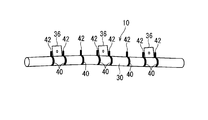
- FIG. 1 is a schematic diagram showing the overall configuration of the curtain airbag device 10.
- the curtain airbag device 10 is provided in a side part of the vehicle interior and is configured to be deployable along a side surface of the vehicle interior in the event of a vehicle emergency, and includes an inflator 22 and a curtain airbag 30. .
- the inflator 22 is formed in a rod shape and supplies high-temperature and high-pressure gas into the curtain airbag 30 according to a detection signal at the time of a vehicle collision.
- the curtain airbag 30 is formed in a bag shape that can be inflated and deployed in a flat shape between the side window 16 of the vehicle and the head of an occupant in the vehicle by sewing a base fabric or the like.
- An opening penetrating the inside and outside of the curtain airbag 30 is formed at one end of the curtain airbag 30 (here, the vehicle rear portion with the curtain airbag 30 attached to the vehicle).
- One end of the inflator 22 on the gas supply side is inserted into the curtain airbag 30 through the opening of the curtain airbag 30.
- the curtain airbag 30 is folded in a long shape in a normal state.
- the curtain airbag 30 is folded by, for example, roll folding, bellows folding, or a combination of these.
- the curtain airbag 30 is provided with an attachment piece 36 for attaching the curtain airbag device 10 to the vehicle.
- the attachment piece 36 is formed, for example, by partially extending a base fabric constituting the curtain airbag 30 outward.
- the attachment piece 36 is attached and fixed to the vehicle via an attachment bracket B (see FIGS. 5 and 6) formed by appropriately punching and pressing a metal plate or the like. That is, the attachment piece 36 is attached to the attachment bracket B via an attachment structure such as a sandwiching structure between the screw head or nut and the attachment bracket B. Then, the mounting bracket B is attached to the vehicle via a fixing structure such as a hooking structure or a screwing structure, so that the curtain airbag 30 folded in a long shape has a roof above the side window 16. Attached along the side rail 12.
- the curtain airbag 30 is covered with a vehicle interior panel or the like so that it cannot be seen from the vehicle interior.
- the gas supplied from the inflator 22 is introduced into the curtain airbag 30.
- the curtain airbag 30 inflated thereby opens the space between the interior panel and the roof side rail 12 and expands toward the vehicle interior, and is flat between the vehicle side window 16 and the head of the vehicle occupant. Inflated and deployed in a bag shape (see curtain airbag 30 shown by a two-dot chain line in FIG. 1).
- the curtain airbag device 10 includes an adhesive tape 40 as a long holding body wound around a curtain airbag 30 folded in a long shape.
- FIG. 2 is an explanatory view showing a state in which the adhesive tape 40 is wound around the curtain airbag device 10.
- the adhesive tape 40 is obtained by forming an adhesive layer 40a on one main surface of a flexible belt-like sheet member.
- acetate fiber or the like can be used, and as the adhesive layer 40a, an adhesive (including an adhesive) that can be bonded to the counterpart member by applying pressure can be used.
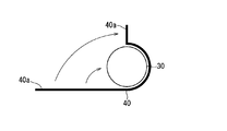
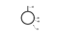
- the adhesive tape 40 is wound around, for example, a curtain airbag 30 folded in a long shape as follows. That is, as shown in FIG. 3, the adhesive tape 40 is wound around the curtain airbag 30 such that the surface of the adhesive tape 40 on the side of the adhesive layer 40 a is in contact with the surface of the curtain airbag 30. At this time, one end of the adhesive tape 40 is extended outward (upward in FIG. 3) from a predetermined position (upper position in FIG. 3) around the outer periphery of the curtain airbag 30. The extension position of one end of the adhesive tape 40 may be positioned with reference to the mounting piece 36 or the folded shape of the curtain airbag 30 as will be described later. And as shown in FIG.
- the adhesive layer 40a of the other end part of the adhesive tape 40 wound around the curtain airbag 30 and the adhesive layer 40a of the one end part of the adhesive tape 40 are abutted and joined. Thereby, both ends which are a part of adhesive tape 40 are extended outward from the predetermined position (here upper position) of the outer periphery of curtain airbag 30 folded in a long shape.
- the outwardly extending portion 42 protrudes radially outward in the cross-sectional shape of the curtain airbag 30 folded in a long shape, and constitutes a twist identifying mark 42.
- the adhesive layer 40a at one end of the adhesive tape 40 and the adhesive layer at the other end need not completely overlap, and the end adhesive layer 40a may be exposed to the outside.
- the adhesive tape 40 When the adhesive tape 40 is wound around the curtain airbag 30, the adhesive tape 40 may be cut into a predetermined length in advance, or the adhesive tape 40 is wound around a winding core.
- the winding operation may be performed in a state where the winding operation is performed, and after the winding operation, the portion of the adhesive tape 40 that has been wound may be separated from the portion wound around the core.
- the belt-like sheet member that is the base material of the adhesive tape 40 preferably has a configuration that can be easily cut in the width direction from the viewpoint of workability.
- the belt-like sheet member is constituted by a cloth-like sheet such as acetate fiber
- the strength of the warp yarn along the longitudinal direction of the belt-like sheet member is smaller than the strength of the weft yarn along the width direction of the belt-like sheet member. It is preferable to do.
- the adhesive tape 40 is attached to a plurality of locations in the longitudinal direction of the curtain airbag 30 folded in a long shape.
- the position where the adhesive tape 40 is provided on the folded curtain airbag 30 preferably includes the side position of the mounting piece 36 (that is, the side position of the mounting portion on the vehicle).
- the curtain airbag 30 can be maintained in a compact and well-folded form at the side position of the attachment piece 36.
- the curtain airbag 30 is less likely to interfere with the attachment piece 36 and its peripheral portion, and the curtain airbag device 10 is smoothly attached to the vehicle. Because it can.
- the adhesive tape 40 is provided in at least one place between the adjacent mounting pieces 36, and the mark 42 is provided on the adhesive tape 40. This is because the presence or absence of twist of the curtain airbag 30 can be confirmed between the adjacent mounting pieces 36.
- all of the adhesive tape 40 wound around the curtain airbag 30 has the mark 42. It is preferable that the extending position of the mark 42 with respect to the outer periphery of the folded curtain airbag 30 is uniform in all the adhesive tapes 40. For example, all the marks 42 may be aligned so as to extend above the folded curtain airbag 30.
- the adhesive tape 40 is provided at both side positions of each attachment piece 36 and at least one position between the adjacent attachment pieces 36, and the marks 42 are provided on all the adhesive tapes 40. Is preferred.
- a preferable aspect of the extending position of the mark 42 will be described in relation to the folded form of the curtain airbag 30.
- the curtain airbag 30 is folded into a flat roll shape, it is finally folded in two from the flat shape and folded into a long shape as shown in FIG. And
- the curtain airbag 30 folded into a flat roll shape in the horizontal direction is folded in two so that the center line in the width direction of the upper surface thereof is a valley line, and both side edges are abutted upward. ing.
- the seam 38 is formed in the upper part of the curtain airbag 30 folded in a long shape.
- 5 and 6 are explanatory views of a cross-sectional portion of the curtain airbag 30 where the attachment piece 36 is provided.
- the curtain airbag 30 may be folded in a bellows shape.
- the curtain airbag 30 is bonded at a seam 38 in the final folded state.
- the mark 42 by the tape 40 extends outward. More specifically, the adhesive layers 40a at both ends of the adhesive tape 40 are abutted and joined at the outer position of the joint 38, and the mark 42 resulting from the joint extends on the outward extension of the joint 38. Like that. Thereby, when forming the mark 42, the both-sides edge part of the curtain airbag 30 can be brought together so that the joint line 38 may be plugged, and it is easy to maintain the folding form of the curtain airbag 30 more reliably.
- the curtain airbag device 10 configured in this way is attached to a vehicle, it can be confirmed that the curtain airbag 30 is not twisted using the mark 42 as a clue. That is, when the curtain airbag 30 is not twisted, as shown in FIGS. 1 and 2, the marks 42 of all the adhesive tapes 40 face in the same direction (here, the upward direction). On the other hand, when the curtain airbag 30 is twisted, as shown in FIG. 8, the marks 42 of some of the adhesive tapes 40 face in different directions from the marks 42 of the other adhesive tapes 40. End up. In FIG. 8, the third mark 42 from the right is directed downward, and the front and rear marks thereof are directed obliquely upward. For this reason, the presence or absence of twist of the curtain airbag 30 can be easily confirmed during and after the installation of the curtain airbag device 10.
- a twist identifying mark 42 is formed by extending a part of the adhesive tape 40 outward from the outer periphery of the folded curtain airbag 30. Therefore, the mark 42 can be attached by a simple operation while suppressing an increase in cost. That is, the mark 42 can be easily attached by a partial device when the adhesive tape 40 is wound around the curtain airbag 30.
- the adhesive tape 40 is used as a long holding body that keeps the curtain airbag 30 in a folded form, the mark 42 can be easily formed while the adhesive tape 40 is easily wrapped around the curtain airbag 30. Can do.
- the adhesive tape 40 is wound around the curtain airbag 30, the adhesive tape 40 is not easily displaced from the curtain airbag 30, and the position of the mark 42 is also difficult to be displaced. For this reason, the presence or absence of twist can be confirmed more reliably.
- the mark 42 can be easily formed by bonding the adhesive layers 40a of the adhesive tape 40 together.
- the marks 42 are formed by bonding the adhesive layers 40a at both ends of the adhesive tape 40, the adhesive tape 40 is wound around the curtain airbag 30 and the ends are bonded together. If the operation of maintaining the form is performed, the mark 42 can be formed, and the mark 42 can be easily formed.
- the structure which joined the adhesive layers 40a of the both ends of the adhesive tape 40 compared with the structure which wound the edge part of the adhesive tape 40 around the own back surface (adhesive layer is an inner surface) of the adhesive tape, and processed.
- Adhesive strength is high and it is difficult to peel off. For this reason, the folded form of the curtain airbag 30 can be held more reliably.
- the part which joined the adhesive layers 40a of the both ends of the adhesive tape 40 is easy to be parted easily by the force which spreads to the radial direction outer side of the wound adhesive tape. For this reason, when the curtain airbag 30 is inflated and deployed, both end portions of the adhesive tape 40 can be easily separated.
- a mark 42 formed by extending a part of the adhesive tape 40 outward from the outer periphery of the curtain airbag 30 is located outside the seam 38 in the final two-folded form of the curtain airbag 30. Is formed. For this reason, when the mark 42 is formed, both side edges of the curtain airbag 30 can be brought together at the joint 38. For example, in the above-described embodiment, when the adhesive layers 40 a at both ends of the adhesive tape 40 are abutted and joined together, both side edges of the curtain airbag 30 can be brought together at the joint 38. For this reason, it is easy to keep the folded curtain airbag 30 in a more compact and constant form.
- the curtain airbag 30 when the curtain airbag 30 is inflated and deployed, the curtain airbag 30 is first inflated so as to open the joint 38, so that the joint portions of the adhesive layers 40a at both ends of the adhesive tape 40 are easily separated, The winding state by the adhesive tape 40 is easily released.
- the curtain airbag device 10 that is provided in a side part of the vehicle interior and that is deployed along the side of the vehicle interior in the event of an emergency of the vehicle has been described. It may be. That is, the airbag device is folded in a long shape in a normal state, and any airbag device that expands in a flat shape from the folded shape may be used.
- the mark 42 may be omitted at the end of the curtain airbag 30 or the like.
- the marks 42 are provided on all the adhesive tapes 40.
- all the marks 42 are aligned in the outer periphery of the curtain airbag 30, but this is not essential.
- the position of the mark 42 at the side position of the attachment piece 36 may be different from the position of the mark 42 between the attachment pieces 36.
- the example in which the mark 42 is formed by the adhesive tape 40 is not limited to the above example.
- the middle part in the longitudinal direction of the adhesive tape 40 wound around the curtain airbag 30 is pinched outward, and the adhesive layer 40a at the pinched portion is joined together to form the mark 142 May be.
- the end of the adhesive tape 40 may be wound around the other outer periphery of the adhesive tape 40.
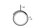
- one end of the adhesive tape 40 wound around the curtain airbag 30 is pinched outward, and the adhesive layer 40a at the pinched portion is joined to mark 242 May be formed. That is, in the above embodiment, the mark 42 is formed by both ends of the adhesive tape 40, but in the present modification, the mark 242 is formed by one end of the adhesive tape 40. In this case, a portion other than the portion where the mark 242 is formed in one end portion of the adhesive tape 40 may be wound around the other outer periphery of the adhesive tape 40.
- the end of the adhesive tape 40 that is to be wound around the curtain airbag 30 is protruded to the outside in the width direction of the adhesive tape 40 to be wound, and the protruding end is twisted for identifying the twist. It is good also as a mark.
- the long holding body wound around the curtain airbag 30 does not necessarily need to be the adhesive tape 40.
- a string or a thread may be used as the long holding body, and the knot may be twisted and used as a mark for identification.
Abstract
Marks for detecting torsion are rendered applicable as easily as possible. Disclosed is an air bag device which is equipped with an inflator capable of supplying a gas and an air bag that has been folded into a long form and can be expanded and unfolded by gas supply from the inflator. The air bag has continuous-form holders, e.g., adhesive tapes, that have been wound therearound. The continuous-form holders partly project outward from the periphery of the air bag to configure marks for detecting torsion.
Description
この発明は、車両緊急時に作動するインフレータのガスによって膨張するエアバッグに関し、特にエアバッグを車両に取りつける際にエアバッグのねじれを抑制する技術に関する。
The present invention relates to an airbag that is inflated by gas of an inflator that operates in the event of a vehicle emergency, and more particularly to a technique for suppressing twisting of the airbag when the airbag is attached to a vehicle.
従来、サイドエアバッグ装置のエアバッグとして、特許文献1に開示のものがある。
Conventionally, as an airbag of a side airbag device, there is one disclosed in Patent Document 1.
特許文献1には、折畳まれたエアバッグの周囲にねじれ識別手段を配設した構成が開示されている。ねじれ識別手段としては、折り崩れ防止のテープ材に、ペン等によって印を付する構成が開示されている。
Patent Document 1 discloses a configuration in which twist identifying means is disposed around a folded airbag. As the twist identifying means, a configuration is disclosed in which a folding prevention tape material is marked with a pen or the like.
しかしながら、特許文献1に開示の技術では、折り崩れ防止のテープ材に、印を付する作業が別途必要となり、作業の煩雑化を招く。
However, the technique disclosed in Patent Document 1 requires a separate work for marking the tape material for preventing the collapse, resulting in complicated work.
そこで、この発明は、ねじれ識別用のマークを、なるべく簡易な作業で付することができるようにすることを目的とする。
Therefore, an object of the present invention is to make it possible to attach a mark for twist identification with as simple an operation as possible.
上記課題を解決するため、第1の態様に係るエアバッグ装置は、ガスを供給可能なインフレータと、長尺状に折畳まれ、前記インフレータからのガス供給によって膨張展開可能なエアバッグと、一部分が前記エアバッグの外周囲から外方に延出するように、前記エアバッグに巻付けられた長尺状保持体とを備える。
In order to solve the above-described problem, an airbag apparatus according to a first aspect includes an inflator capable of supplying gas, an airbag that is folded into a long shape and that can be inflated and deployed by gas supply from the inflator, and a part thereof Is provided with a long holding body wound around the airbag so as to extend outward from the outer periphery of the airbag.
第2の態様は、第1の態様に係るエアバッグ装置であって、前記長尺状保持体は、前記エアバッグに巻付けられた接着テープとされている。
The second aspect is the airbag device according to the first aspect, wherein the elongated holding body is an adhesive tape wound around the airbag.
第3の態様は、第2の態様に係るエアバッグ装置であって、前記接着テープの接着層同士が接合されることにより、前記長尺状保持体の一部分が前記エアバッグの外周囲から外方に延出されている。
A 3rd aspect is an airbag apparatus which concerns on a 2nd aspect, Comprising: Adhesive layers of the said adhesive tape are joined, A part of the said elongate holding body is outside from the outer periphery of the said airbag. It is extended towards.
第4の態様は、第3の態様に係るエアバッグ装置であって、前記接着テープの両端部の接着層同士が接合されることにより、前記長尺状保持体の一部分が前記エアバッグの外周囲から外方に延出されている。
A fourth aspect is the airbag apparatus according to the third aspect, wherein the adhesive layers at both ends of the adhesive tape are joined together so that a part of the elongated holding body is outside the airbag. It extends outward from the surroundings.
第5の態様は、第1~第4のいずれか1つの態様に係るエアバッグ装置であって、前記エアバッグは、最終的に2つ折りされた状態で長尺状に折畳まれており、前記長尺状保持体は、前記エアバッグが最終的に二つ折りされた形態の合せ目で、外方に延出している。
A fifth aspect is the airbag device according to any one of the first to fourth aspects, wherein the airbag is folded into a long shape in a state where the airbag is finally folded in two, The elongate holding body extends outwardly at a joint where the airbag is finally folded in half.
第1の態様によると、長尺状保持体の一部分をエアバッグの外周囲から外方に延出させることにより、ねじれ識別用のマークを、簡易な作業で付することができる。
According to the first aspect, by extending a part of the long holding body outward from the outer periphery of the airbag, a mark for twist identification can be attached with a simple operation.
第2の態様によると、前記長尺状保持体は、前記エアバッグに巻付けられた接着テープであるため、比較的簡易にエアバッグに巻付けつつねじれ識別用のマークを付与することができると共に、巻付後にずれ難い。
According to the second aspect, since the elongated holding body is an adhesive tape wound around the airbag, it is possible to impart a twist identifying mark while winding the airbag relatively easily. In addition, it is difficult to slip after winding.
第3の態様によると、前記接着テープの接着層同士を接合させることにより、ねじれ識別用のマークを、簡易な作業で付することができる。
According to the third aspect, by joining the adhesive layers of the adhesive tape, a mark for twist identification can be attached with a simple operation.
第4の態様によると、前記接着テープの両端部の接着層同士を接合させることにより、ねじれ識別用のマークを、簡易な作業で付することができる。また、エアバッグの膨張時には、前記接着テープの端部の接着層同士の接合部分を比較的容易に分離させることができる。
According to the fourth aspect, by joining the adhesive layers at both ends of the adhesive tape, a mark for twist identification can be attached with a simple operation. Further, when the airbag is inflated, the joint portion between the adhesive layers at the end of the adhesive tape can be separated relatively easily.
第5の態様によると、一部分を前記エアバッグの外周囲から外方に延出させつつ、長尺状保持体をエアバッグに巻付ける際に、二つ折りされた形態の合せ目においてエアバッグの両側縁部を寄せ合わせることができるため、エアバッグの折畳み形態を保ち易い。特に、長尺状保持体として接着テープを用い、前記合せ目で前記接着テープの両端部の接着層同士を接合させた場合に、カーテンエアバッグの膨張展開時には、カーテンエアバッグは、まず、合せ目を開くように膨張するため、接着テープの両端部の接着層同士の接合部分が容易に分離し、接着テープによる巻付状態が容易に解除される。
According to the fifth aspect, when the elongate holding body is wound around the airbag with a part extending outward from the outer periphery of the airbag, the airbag is folded at the seam of the folded shape. Since both side edges can be brought together, it is easy to maintain the folded form of the airbag. In particular, when an adhesive tape is used as a long holding body and the adhesive layers at both ends of the adhesive tape are joined to each other at the joint, the curtain airbag is first aligned when the curtain airbag is inflated and deployed. Since it expand | swells so that eyes may open, the junction part of the adhesive layers of the both ends of an adhesive tape will isolate | separate easily, and the winding state by an adhesive tape will be cancelled | released easily.
実施形態に係るカーテンエアバッグ装置について説明する。図1はカーテンエアバッグ装置10の全体構成を示す概略図である。
The curtain airbag device according to the embodiment will be described. FIG. 1 is a schematic diagram showing the overall configuration of the curtain airbag device 10.
このカーテンエアバッグ装置10は、車室内側方部位に設けられ、車両の緊急時に車室内側面に沿って展開動作可能に構成されるものであり、インフレータ22とカーテンエアバッグ30とを備えている。
The curtain airbag device 10 is provided in a side part of the vehicle interior and is configured to be deployable along a side surface of the vehicle interior in the event of a vehicle emergency, and includes an inflator 22 and a curtain airbag 30. .
インフレータ22は、棒状に形成されており、車両の衝突時の検知信号に応じて、上記カーテンエアバッグ30内に高温高圧ガスを供給するようになっている。
The inflator 22 is formed in a rod shape and supplies high-temperature and high-pressure gas into the curtain airbag 30 according to a detection signal at the time of a vehicle collision.
カーテンエアバッグ30は、基布を縫製等することで、車両のサイドウインドウ16と車両内の乗員の頭部との間で扁平形状に膨張展開可能な袋状に形成されている。このカーテンエアバッグ30の一端部(ここでは、カーテンエアバッグ30を車両に取付けた状態で車両後方部分)には、カーテンエアバッグ30の内外を貫通する開口が形成されている。インフレータ22のうちガスを供給する側の一端部は、カーテンエアバッグ30の前記開口を通ってカーテンエアバッグ30内に挿入されている。
The curtain airbag 30 is formed in a bag shape that can be inflated and deployed in a flat shape between the side window 16 of the vehicle and the head of an occupant in the vehicle by sewing a base fabric or the like. An opening penetrating the inside and outside of the curtain airbag 30 is formed at one end of the curtain airbag 30 (here, the vehicle rear portion with the curtain airbag 30 attached to the vehicle). One end of the inflator 22 on the gas supply side is inserted into the curtain airbag 30 through the opening of the curtain airbag 30.
このカーテンエアバッグ30は、通常状態では、長尺状に折畳まれている。カーテンエアバッグ30の折畳みは、例えば、ロール状の折畳み、蛇腹状の折畳み、或はこれらの組合わせによる折畳み等によりなされる。
The curtain airbag 30 is folded in a long shape in a normal state. The curtain airbag 30 is folded by, for example, roll folding, bellows folding, or a combination of these.
このカーテンエアバッグ30には、本カーテンエアバッグ装置10を車両に取付けるための取付片36が設けられている。取付片36は、例えば、カーテンエアバッグ30を構成する基布を部分的に外方に延出させることにより形成されている。この取付片36は、金属板等を適宜打抜きプレス加工等することにより形成された取付ブラケットB(図5及び図6参照)等を介して車両に取付固定される。すなわち、取付片36は、ネジ頭又はナットと取付ブラケットBとの挟込み構造等の取付構造を介して取付ブラケットBに取付けられている。そして、取付ブラケットBが、車両に対して引っかけ構造、ねじ止構造等の固定構造を介して取付けられることで、長尺状に折畳まれたカーテンエアバッグ30が、サイドウインドウ16上方にあるルーフサイドレール12に沿って取付けられる。この取付状態では、カーテンエアバッグ30は、車室内装パネル等によって覆われており、車室内から見えないようになっている。そして、車両の側面衝突時等の車両緊急時には、インフレータ22から供給されるガスがカーテンエアバッグ30内に導入される。これにより膨張したカーテンエアバッグ30は、内装パネルとルーフサイドレール12との間を割開いて車室内に向けて展開し、車両のサイドウインドウ16と車両の乗員の頭部との間で扁平な袋状に膨張展開するようになっている(図1において2点鎖線で示すカーテンエアバッグ30参照)。
The curtain airbag 30 is provided with an attachment piece 36 for attaching the curtain airbag device 10 to the vehicle. The attachment piece 36 is formed, for example, by partially extending a base fabric constituting the curtain airbag 30 outward. The attachment piece 36 is attached and fixed to the vehicle via an attachment bracket B (see FIGS. 5 and 6) formed by appropriately punching and pressing a metal plate or the like. That is, the attachment piece 36 is attached to the attachment bracket B via an attachment structure such as a sandwiching structure between the screw head or nut and the attachment bracket B. Then, the mounting bracket B is attached to the vehicle via a fixing structure such as a hooking structure or a screwing structure, so that the curtain airbag 30 folded in a long shape has a roof above the side window 16. Attached along the side rail 12. In this attached state, the curtain airbag 30 is covered with a vehicle interior panel or the like so that it cannot be seen from the vehicle interior. In the event of a vehicle emergency such as a vehicle side collision, the gas supplied from the inflator 22 is introduced into the curtain airbag 30. The curtain airbag 30 inflated thereby opens the space between the interior panel and the roof side rail 12 and expands toward the vehicle interior, and is flat between the vehicle side window 16 and the head of the vehicle occupant. Inflated and deployed in a bag shape (see curtain airbag 30 shown by a two-dot chain line in FIG. 1).
また、このカーテンエアバッグ装置10は、長尺状に折畳まれたカーテンエアバッグ30に巻付けられた長尺状保持体としての接着テープ40を備えている。図2はカーテンエアバッグ装置10に接着テープ40が巻付けられた状態を示す説明図である。
Also, the curtain airbag device 10 includes an adhesive tape 40 as a long holding body wound around a curtain airbag 30 folded in a long shape. FIG. 2 is an explanatory view showing a state in which the adhesive tape 40 is wound around the curtain airbag device 10.
接着テープ40は、柔軟な帯状シート部材の一主面に接着層40aを形成したものである。帯状シート部材としては、アセテート繊維等を用いることができ、接着層40aとしては、圧を加えることにより相手側の部材に接合可能な接着剤(粘着剤を含む)を用いることができる。
The adhesive tape 40 is obtained by forming an adhesive layer 40a on one main surface of a flexible belt-like sheet member. As the belt-like sheet member, acetate fiber or the like can be used, and as the adhesive layer 40a, an adhesive (including an adhesive) that can be bonded to the counterpart member by applying pressure can be used.
この接着テープ40は、例えば、次のようにして長尺状に折畳まれたカーテンエアバッグ30に巻付けられている。すなわち、図3に示すように、接着テープ40の接着層40a側の面をカーテンエアバッグ30の表面に接触させるようにして、接着テープ40をカーテンエアバッグ30に巻付ける。この際、接着テープ40の一端部がカーテンエアバッグ30の外周囲の所定位置(図3では上方位置)から外方(図3では上方)に延出するようにする。接着テープ40の一端部の延出位置は、取付片36或は後述するようにカーテンエアバッグ30の折畳み形状を基準にして位置決めするとよい。そして、図4に示すように、カーテンエアバッグ30に巻付けられた接着テープ40の他端部の接着層40aと接着テープ40の一端部の接着層40aとを突合わせて接合させる。これにより、接着テープ40の一部分である両端部が、長尺状に折畳まれたカーテンエアバッグ30の外周囲の所定位置(ここでは上方位置)から外方に延出する。この外方延出部分42は、長尺状に折畳まれたカーテンエアバッグ30の断面形状において径方向外側に突出しており、ねじれ識別用のマーク42を構成する。接着テープ40の一端部の接着層40aと他端部の接着層とは完全に重なっている必要はなく、端部の接着層40aが外部に露出していてもよい。
The adhesive tape 40 is wound around, for example, a curtain airbag 30 folded in a long shape as follows. That is, as shown in FIG. 3, the adhesive tape 40 is wound around the curtain airbag 30 such that the surface of the adhesive tape 40 on the side of the adhesive layer 40 a is in contact with the surface of the curtain airbag 30. At this time, one end of the adhesive tape 40 is extended outward (upward in FIG. 3) from a predetermined position (upper position in FIG. 3) around the outer periphery of the curtain airbag 30. The extension position of one end of the adhesive tape 40 may be positioned with reference to the mounting piece 36 or the folded shape of the curtain airbag 30 as will be described later. And as shown in FIG. 4, the adhesive layer 40a of the other end part of the adhesive tape 40 wound around the curtain airbag 30 and the adhesive layer 40a of the one end part of the adhesive tape 40 are abutted and joined. Thereby, both ends which are a part of adhesive tape 40 are extended outward from the predetermined position (here upper position) of the outer periphery of curtain airbag 30 folded in a long shape. The outwardly extending portion 42 protrudes radially outward in the cross-sectional shape of the curtain airbag 30 folded in a long shape, and constitutes a twist identifying mark 42. The adhesive layer 40a at one end of the adhesive tape 40 and the adhesive layer at the other end need not completely overlap, and the end adhesive layer 40a may be exposed to the outside.
なお、接着テープ40をカーテンエアバッグ30に巻付ける際、接着テープ40を予め必要な所定長に切断しておいてもよいし、或は、接着テープ40が巻回収容用の巻心に巻かれた状態で上記巻付作業を行い、巻付作業終了後に、接着テープ40のうち巻付け作業された部分を、巻心に巻かれた部分から切離すようにしてもよい。
When the adhesive tape 40 is wound around the curtain airbag 30, the adhesive tape 40 may be cut into a predetermined length in advance, or the adhesive tape 40 is wound around a winding core. The winding operation may be performed in a state where the winding operation is performed, and after the winding operation, the portion of the adhesive tape 40 that has been wound may be separated from the portion wound around the core.
また、接着テープ40の基材となる帯状シート部材については、作業性の観点からその幅方向に容易に切断可能な構成であることが好ましい。そのためには、帯状シート部材をアセテート繊維等の布状のシートによって構成する場合、帯状シート部材の長手方向に沿った縦糸の強度を、帯状シート部材の幅方向に沿った横糸の強度よりも小さくすることが好ましい。
Further, the belt-like sheet member that is the base material of the adhesive tape 40 preferably has a configuration that can be easily cut in the width direction from the viewpoint of workability. For that purpose, when the belt-like sheet member is constituted by a cloth-like sheet such as acetate fiber, the strength of the warp yarn along the longitudinal direction of the belt-like sheet member is smaller than the strength of the weft yarn along the width direction of the belt-like sheet member. It is preferable to do.
接着テープ40は、長尺状に折畳まれたカーテンエアバッグ30の長手方向において複数箇所に取付けられている。
The adhesive tape 40 is attached to a plurality of locations in the longitudinal direction of the curtain airbag 30 folded in a long shape.
折畳まれたカーテンエアバッグ30に対して接着テープ40を設ける位置は、上記取付片36の側方位置(つまり、車両への取付部位側方位置)を含むことが好ましい。取付片36の側方位置で、接着テープ40をカーテンエアバッグ30に巻付けると、取付片36の側方位置においてカーテンエアバッグ30をコンパクトにまとまりよく折畳んだ形態に維持することができる。これにより、取付片36を介してカーテンエアバッグ装置10を車両に取付ける際に、カーテンエアバッグ30が取付片36及びその周辺部位に干渉し難くなり、カーテンエアバッグ装置10を円滑に車両に取付けることができるからである。
The position where the adhesive tape 40 is provided on the folded curtain airbag 30 preferably includes the side position of the mounting piece 36 (that is, the side position of the mounting portion on the vehicle). When the adhesive tape 40 is wound around the curtain airbag 30 at the side position of the attachment piece 36, the curtain airbag 30 can be maintained in a compact and well-folded form at the side position of the attachment piece 36. As a result, when the curtain airbag device 10 is attached to the vehicle via the attachment piece 36, the curtain airbag 30 is less likely to interfere with the attachment piece 36 and its peripheral portion, and the curtain airbag device 10 is smoothly attached to the vehicle. Because it can.
また、接着テープ40が隣合う取付片36の間の少なくとも1箇所に設けられ、その接着テープ40にマーク42が設けられていることが好ましい。これにより、隣合う取付片36間でカーテンエアバッグ30のねじれの有無を確認できるからである。
Further, it is preferable that the adhesive tape 40 is provided in at least one place between the adjacent mounting pieces 36, and the mark 42 is provided on the adhesive tape 40. This is because the presence or absence of twist of the curtain airbag 30 can be confirmed between the adjacent mounting pieces 36.
また、カーテンエアバッグ30のねじれの有無を確認するためには、カーテンエアバッグ30に巻付けられた接着テープ40の全てがマーク42を有していることが好ましい。折畳まれたカーテンエアバッグ30の外周囲に対するマーク42の延出位置は、全ての接着テープ40において揃っていることが好ましい。例えば、全てのマーク42が折畳まれたカーテンエアバッグ30の上方に延出するように揃えられているとよい。
Further, in order to confirm whether the curtain airbag 30 is twisted or not, it is preferable that all of the adhesive tape 40 wound around the curtain airbag 30 has the mark 42. It is preferable that the extending position of the mark 42 with respect to the outer periphery of the folded curtain airbag 30 is uniform in all the adhesive tapes 40. For example, all the marks 42 may be aligned so as to extend above the folded curtain airbag 30.
つまり、一般的な構成としては、各取付片36の両側方位置と、隣合う取付片36間の少なくとも1箇所の位置とに接着テープ40を設け、全ての接着テープ40にマーク42を設けることが好ましい。
That is, as a general configuration, the adhesive tape 40 is provided at both side positions of each attachment piece 36 and at least one position between the adjacent attachment pieces 36, and the marks 42 are provided on all the adhesive tapes 40. Is preferred.
マーク42の延出位置の好ましい態様について、カーテンエアバッグ30の折畳み形態との関係で説明する。
A preferable aspect of the extending position of the mark 42 will be described in relation to the folded form of the curtain airbag 30.
すなわち、図5に示すように、カーテンエアバッグ30が扁平なロール状に折畳まれた後、図6に示すように、最終的に扁平形態から二つ折りされて長尺状に折畳まれるとする。ここでは、水平方向に扁平なロール状に折畳まれたカーテンエアバッグ30が、その上面の幅方向中央線を谷線とするように二つ折りされており、その両側縁部が上方で突合わされている。これにより、長尺状に折畳まれたカーテンエアバッグ30において、上部に合せ目38が形成されている。なお、図5及び図6は、カーテンエアバッグ30のうち取付片36が設けられた断面部分での説明図である。最終的な二つ折り形態の前には、カーテンエアバッグ30は蛇腹状に折畳まれていてもよい。
That is, as shown in FIG. 5, after the curtain airbag 30 is folded into a flat roll shape, it is finally folded in two from the flat shape and folded into a long shape as shown in FIG. And Here, the curtain airbag 30 folded into a flat roll shape in the horizontal direction is folded in two so that the center line in the width direction of the upper surface thereof is a valley line, and both side edges are abutted upward. ing. Thereby, the seam 38 is formed in the upper part of the curtain airbag 30 folded in a long shape. 5 and 6 are explanatory views of a cross-sectional portion of the curtain airbag 30 where the attachment piece 36 is provided. Prior to the final bi-fold configuration, the curtain airbag 30 may be folded in a bellows shape.
このように折畳まれたカーテンエアバッグ30に対して接着テープ40を巻付けるにあたっては、図7に示すように、カーテンエアバッグ30が最終的に二つ折りされた形態の合せ目38において、接着テープ40によるマーク42が外方に延出するようにすることが好ましい。より具体的には、接着テープ40の両端部の接着層40a同士を合せ目38の外方位置で突合わせて接合し、その接合によるマーク42が合せ目38の外方延長上に延出するようにする。これにより、マーク42を形成する際に、合せ目38を塞ぐようにカーテンエアバッグ30の両側縁部を寄せ合わせることができ、カーテンエアバッグ30の折畳み形態をより確実に維持し易い。
When the adhesive tape 40 is wound around the curtain airbag 30 folded in this way, as shown in FIG. 7, the curtain airbag 30 is bonded at a seam 38 in the final folded state. It is preferable that the mark 42 by the tape 40 extends outward. More specifically, the adhesive layers 40a at both ends of the adhesive tape 40 are abutted and joined at the outer position of the joint 38, and the mark 42 resulting from the joint extends on the outward extension of the joint 38. Like that. Thereby, when forming the mark 42, the both-sides edge part of the curtain airbag 30 can be brought together so that the joint line 38 may be plugged, and it is easy to maintain the folding form of the curtain airbag 30 more reliably.
このように構成されたカーテンエアバッグ装置10を車両に取付けるにあたっては、マーク42を手がかりとして、カーテンエアバッグ30がねじれていないことを確認することができる。すなわち、カーテンエアバッグ30がねじれていない場合には、図1及び図2に示すように、全ての接着テープ40のマーク42が同じ方向(ここでは上方向)を向く。これに対して、カーテンエアバッグ30がねじれてしまった場合には、図8に示すように、一部の接着テープ40のマーク42が、他の接着テープ40のマーク42とは異なる方向を向いてしまう。図8では右から3つめのマーク42が下を向き、その前後のマークが斜め上方を向いている。このため、カーテンエアバッグ装置10の取付作業中、取付作業後において、カーテンエアバッグ30のねじれの有無を容易に確認することができる。
When the curtain airbag device 10 configured in this way is attached to a vehicle, it can be confirmed that the curtain airbag 30 is not twisted using the mark 42 as a clue. That is, when the curtain airbag 30 is not twisted, as shown in FIGS. 1 and 2, the marks 42 of all the adhesive tapes 40 face in the same direction (here, the upward direction). On the other hand, when the curtain airbag 30 is twisted, as shown in FIG. 8, the marks 42 of some of the adhesive tapes 40 face in different directions from the marks 42 of the other adhesive tapes 40. End up. In FIG. 8, the third mark 42 from the right is directed downward, and the front and rear marks thereof are directed obliquely upward. For this reason, the presence or absence of twist of the curtain airbag 30 can be easily confirmed during and after the installation of the curtain airbag device 10.
以上のように構成されたカーテンエアバッグ装置10によると、接着テープ40の一部分を折畳まれたカーテンエアバッグ30の外周囲から外方に延出させることにより、ねじれ識別用のマーク42を形成しているため、当該マーク42を、コスト増を抑制しつつ簡易な作業で付することができる。すなわち、接着テープ40をカーテンエアバッグ30に巻付ける際の部分的な工夫によって、マーク42を容易に付することができる。
According to the curtain airbag device 10 configured as described above, a twist identifying mark 42 is formed by extending a part of the adhesive tape 40 outward from the outer periphery of the folded curtain airbag 30. Therefore, the mark 42 can be attached by a simple operation while suppressing an increase in cost. That is, the mark 42 can be easily attached by a partial device when the adhesive tape 40 is wound around the curtain airbag 30.
また、カーテンエアバッグ30を折畳み形態に保つ長尺状保持体として接着テープ40を用いているため、当該接着テープ40をカーテンエアバッグ30に容易に巻付けつつ、マーク42を容易に形成することができる。しかも、接着テープ40をカーテンエアバッグ30に巻付けた状態では、接着テープ40がカーテンエアバッグ30から位置ずれし難く、マーク42の位置も位置ずれし難い。このため、ねじれの有無をより確実に確認することができる。
Moreover, since the adhesive tape 40 is used as a long holding body that keeps the curtain airbag 30 in a folded form, the mark 42 can be easily formed while the adhesive tape 40 is easily wrapped around the curtain airbag 30. Can do. In addition, when the adhesive tape 40 is wound around the curtain airbag 30, the adhesive tape 40 is not easily displaced from the curtain airbag 30, and the position of the mark 42 is also difficult to be displaced. For this reason, the presence or absence of twist can be confirmed more reliably.
また、接着テープ40の接着層40a同士を接合させることにより、マーク42を容易に形成することができる。
Further, the mark 42 can be easily formed by bonding the adhesive layers 40a of the adhesive tape 40 together.
しかも、接着テープ40の両端部の接着層40a同士を接合させることにより、マーク42を形成しているため、接着テープ40をカーテンエアバッグ30に巻付けてその両端部同士を接合して巻付け形態を保つ作業を行えば、マーク42を形成することができ、マーク42を容易に形成することができる。
In addition, since the marks 42 are formed by bonding the adhesive layers 40a at both ends of the adhesive tape 40, the adhesive tape 40 is wound around the curtain airbag 30 and the ends are bonded together. If the operation of maintaining the form is performed, the mark 42 can be formed, and the mark 42 can be easily formed.
また、接着テープ40の両端部の接着層40a同士を接合させた構成は、接着テープ40の端部を接着テープの自背面(接着層が内側の面)に巻付けて処理した構成と比べて、接着力が大きく、剥がれにくい。このため、カーテンエアバッグ30の折畳み形態をより確実に保持することができる。しかも、接着テープ40の両端部の接着層40a同士を接合させた部分は、巻付けられた接着テープの径方向外側に広がる力によって容易に分断し易い。このため、カーテンエアバッグ30の膨張展開時には、接着テープ40の両端部を容易に分離させることができる。
Moreover, the structure which joined the adhesive layers 40a of the both ends of the adhesive tape 40 compared with the structure which wound the edge part of the adhesive tape 40 around the own back surface (adhesive layer is an inner surface) of the adhesive tape, and processed. Adhesive strength is high and it is difficult to peel off. For this reason, the folded form of the curtain airbag 30 can be held more reliably. And the part which joined the adhesive layers 40a of the both ends of the adhesive tape 40 is easy to be parted easily by the force which spreads to the radial direction outer side of the wound adhesive tape. For this reason, when the curtain airbag 30 is inflated and deployed, both end portions of the adhesive tape 40 can be easily separated.
また、接着テープ40の一部分をカーテンエアバッグ30の外周囲から外方に延出させて形成したマーク42が、カーテンエアバッグ30の最終的2つ折畳み形態における合せ目38の外方に位置して形成されている。このため、マーク42を形成する際に、合せ目38においてカーテンエアバッグ30の両側縁部を寄せ合わせるようにすることができる。例えば、上記実施形態では、接着テープ40の両端部の接着層40a同士を突合わせて接合する際に、合せ目38においてカーテンエアバッグ30の両側縁部を寄せ合わせるようにすることができる。このため、折畳まれたカーテンエアバッグ30をよりコンパクトな一定形態に保ち易い。
Further, a mark 42 formed by extending a part of the adhesive tape 40 outward from the outer periphery of the curtain airbag 30 is located outside the seam 38 in the final two-folded form of the curtain airbag 30. Is formed. For this reason, when the mark 42 is formed, both side edges of the curtain airbag 30 can be brought together at the joint 38. For example, in the above-described embodiment, when the adhesive layers 40 a at both ends of the adhesive tape 40 are abutted and joined together, both side edges of the curtain airbag 30 can be brought together at the joint 38. For this reason, it is easy to keep the folded curtain airbag 30 in a more compact and constant form.
また、カーテンエアバッグ30の膨張展開時には、カーテンエアバッグ30は、まず、合せ目38を開くように膨張するため、接着テープ40の両端部の接着層40a同士の接合部分が容易に分離し、接着テープ40による巻付状態が容易に解除される。
Further, when the curtain airbag 30 is inflated and deployed, the curtain airbag 30 is first inflated so as to open the joint 38, so that the joint portions of the adhesive layers 40a at both ends of the adhesive tape 40 are easily separated, The winding state by the adhesive tape 40 is easily released.
<変形例>
以上のようにこのエアバッグ装置は詳細に説明されたが、上記した説明は、すべての局面において、例示であって、この発明がそれに限定されるものではない。例示されていない無数の変形例が、この発明の範囲から外れることなく想定され得るものと解される。 <Modification>
Although the airbag device has been described in detail as described above, the above description is an exemplification in all aspects, and the present invention is not limited thereto. It is understood that countless variations that are not illustrated can be envisaged without departing from the scope of the present invention.
例えば、上記実施形態では、車室内側方部位に設けられ、車両の緊急時に車室内側面に沿って展開動作するカーテンエアバッグ装置10について説明したが、リアウインドウに沿って展開するエアバッグ装置等であってもよい。すなわち、エアバッグ装置は、通常状態では長尺状に折畳まれており、その折畳み形態から扁平状に展開するものであればよい。
For example, in the above-described embodiment, the curtain airbag device 10 that is provided in a side part of the vehicle interior and that is deployed along the side of the vehicle interior in the event of an emergency of the vehicle has been described. It may be. That is, the airbag device is folded in a long shape in a normal state, and any airbag device that expands in a flat shape from the folded shape may be used.
また、上記実施形態では、複数の接着テープ40の全てにマーク42が設けられた例で説明したが、必ずしもその必要はない。例えば、カーテンエアバッグ30の端部等ではマーク42が省略されていてもよい。もっとも、ねじれの有無を容易に識別するためには、全ての接着テープ40にマーク42が設けられていることが好ましい。また、カーテンエアバッグ30の外周囲において、全てのマーク42の位置が揃っていることが好ましいが、これは必須ではない。例えば、取付片36の側方位置におけるマーク42の位置と、取付片36の間におけるマーク42の位置とが異なっていてもよい。
In the above embodiment, the example in which the marks 42 are provided on all of the plurality of adhesive tapes 40 has been described, but this is not necessarily required. For example, the mark 42 may be omitted at the end of the curtain airbag 30 or the like. However, in order to easily identify the presence or absence of twist, it is preferable that the marks 42 are provided on all the adhesive tapes 40. In addition, it is preferable that all the marks 42 are aligned in the outer periphery of the curtain airbag 30, but this is not essential. For example, the position of the mark 42 at the side position of the attachment piece 36 may be different from the position of the mark 42 between the attachment pieces 36.
また、接着テープ40によってマーク42を形成する例は上記例に限られない。
Further, the example in which the mark 42 is formed by the adhesive tape 40 is not limited to the above example.
例えば、図9に示すように、カーテンエアバッグ30に巻付けられた接着テープ40の長手方向中間部を外方につまみ出すと共に、そのつまみだし部分の接着層40a同士を接合させてマーク142を形成してもよい。この場合、接着テープ40の端部については、接着テープ40の他の外周に巻付けておくとよい。
For example, as shown in FIG. 9, the middle part in the longitudinal direction of the adhesive tape 40 wound around the curtain airbag 30 is pinched outward, and the adhesive layer 40a at the pinched portion is joined together to form the mark 142 May be. In this case, the end of the adhesive tape 40 may be wound around the other outer periphery of the adhesive tape 40.
また、例えば、図10に示すように、カーテンエアバッグ30に巻付けられた接着テープ40の一方の端部を外方につまみ出すと共に、そのつまみだし部分の接着層40a同士を接合させてマーク242を形成してもよい。つまり、上記実施形態では、接着テープ40の両端部によってマーク42を形成しているが、本変形例では、接着テープ40の一方の端部によってマーク242を形成している。この場合、接着テープ40の一方の端部のうちマーク242の形成部分以外の部分については、接着テープ40の他の外周に巻付けておくとよい。
Further, for example, as shown in FIG. 10, one end of the adhesive tape 40 wound around the curtain airbag 30 is pinched outward, and the adhesive layer 40a at the pinched portion is joined to mark 242 May be formed. That is, in the above embodiment, the mark 42 is formed by both ends of the adhesive tape 40, but in the present modification, the mark 242 is formed by one end of the adhesive tape 40. In this case, a portion other than the portion where the mark 242 is formed in one end portion of the adhesive tape 40 may be wound around the other outer periphery of the adhesive tape 40.
その他、接着テープ40のうちカーテンエアバッグ30に巻付ける際の巻はじめとなる端部を、巻付けられる接着テープ40の幅方向外側にはみ出させておき、そのはみ出した端部をねじれ識別用のマークとしてもよい。
In addition, the end of the adhesive tape 40 that is to be wound around the curtain airbag 30 is protruded to the outside in the width direction of the adhesive tape 40 to be wound, and the protruding end is twisted for identifying the twist. It is good also as a mark.
また、カーテンエアバッグ30に巻付けられる長尺状保持体は、必ずしも接着テープ40である必要はない。長尺状保持体として紐又は糸等を用い、その結び目をねじれ識別用のマークとしてもよい。
Further, the long holding body wound around the curtain airbag 30 does not necessarily need to be the adhesive tape 40. A string or a thread may be used as the long holding body, and the knot may be twisted and used as a mark for identification.
10 カーテンエアバッグ装置
22 インフレータ
30 カーテンエアバッグ
38 合せ目
40 接着テープ
40a 接着層
42、142、242 マーク DESCRIPTION OFSYMBOLS 10 Curtain airbag apparatus 22 Inflator 30 Curtain airbag 38 Seam 40 Adhesive tape 40a Adhesive layer 42, 142, 242 Mark
22 インフレータ
30 カーテンエアバッグ
38 合せ目
40 接着テープ
40a 接着層
42、142、242 マーク DESCRIPTION OF
Claims (5)
- ガスを供給可能なインフレータと、
長尺状に折畳まれ、前記インフレータからのガス供給によって膨張展開可能なエアバッグと、
一部分が前記エアバッグの外周囲から外方に延出するように、前記エアバッグに巻付けられた長尺状保持体と、
を備えるエアバッグ装置。 An inflator capable of supplying gas;
An airbag that is folded into a long shape and is inflatable and deployable by gas supply from the inflator;
An elongate holder wound around the airbag such that a portion extends outward from the outer periphery of the airbag;
An airbag device comprising: - 請求項1記載のエアバッグ装置であって、
前記長尺状保持体は、前記エアバッグに巻付けられた接着テープである、エアバッグ装置。 The airbag device according to claim 1,
The said long holding body is an airbag apparatus which is the adhesive tape wound around the said airbag. - 請求項2記載のエアバッグ装置であって、
前記接着テープの接着層同士が接合されることにより、前記長尺状保持体の一部分が前記エアバッグの外周囲から外方に延出されている、エアバッグ装置。 The airbag device according to claim 2,
An airbag device in which a part of the elongated holding body extends outward from the outer periphery of the airbag by bonding the adhesive layers of the adhesive tape to each other. - 請求項3記載のエアバッグ装置であって、
前記接着テープの両端部の接着層同士が接合されることにより、前記長尺状保持体の一部分が前記エアバッグの外周囲から外方に延出されている、エアバッグ装置。 The airbag device according to claim 3,
An airbag device in which a part of the elongated holding body is extended outward from the outer periphery of the airbag by bonding the adhesive layers at both ends of the adhesive tape. - 請求項1~4のいずれか1つに記載のエアバッグ装置であって、
前記エアバッグは、最終的に2つ折りされた状態で長尺状に折畳まれており、
前記長尺状保持体は、前記エアバッグが最終的に二つ折りされた形態の合せ目で、外方に延出している、エアバッグ装置。 The airbag device according to any one of claims 1 to 4,
The airbag is folded into a long shape in a state where it is finally folded in two,
The elongate holding body is an airbag device that extends outward at a seam where the airbag is finally folded in half.
Priority Applications (2)
| Application Number | Priority Date | Filing Date | Title |
|---|---|---|---|
| US13/805,575 US20130087999A1 (en) | 2010-07-05 | 2011-06-17 | Air bag device |
| EP11803436.2A EP2591953A1 (en) | 2010-07-05 | 2011-06-17 | Air bag device |
Applications Claiming Priority (2)
| Application Number | Priority Date | Filing Date | Title |
|---|---|---|---|
| JP2010152791A JP2012011968A (en) | 2010-07-05 | 2010-07-05 | Airbag device |
| JP2010-152791 | 2010-07-05 |
Publications (1)
| Publication Number | Publication Date |
|---|---|
| WO2012005100A1 true WO2012005100A1 (en) | 2012-01-12 |
Family
ID=45441086
Family Applications (1)
| Application Number | Title | Priority Date | Filing Date |
|---|---|---|---|
| PCT/JP2011/063907 WO2012005100A1 (en) | 2010-07-05 | 2011-06-17 | Air bag device |
Country Status (4)
| Country | Link |
|---|---|
| US (1) | US20130087999A1 (en) |
| EP (1) | EP2591953A1 (en) |
| JP (1) | JP2012011968A (en) |
| WO (1) | WO2012005100A1 (en) |
Cited By (1)
| Publication number | Priority date | Publication date | Assignee | Title |
|---|---|---|---|---|
| US8475686B2 (en) | 2008-12-03 | 2013-07-02 | Novaled Ag | Bridged pyridoquinazoline or phenanthroline compounds and organic semiconducting material comprising that compound |
Families Citing this family (10)
| Publication number | Priority date | Publication date | Assignee | Title |
|---|---|---|---|---|
| JP5314919B2 (en) * | 2008-04-23 | 2013-10-16 | 芦森工業株式会社 | Airbag device |
| KR101207394B1 (en) * | 2010-11-02 | 2012-12-04 | 아우토리브 디벨롭먼트 아베 | Anti-twist apparatus for vehicle's curtain air-bag |
| JP5783818B2 (en) * | 2011-06-23 | 2015-09-24 | 芦森工業株式会社 | Airbag device |
| JP5848091B2 (en) * | 2011-10-26 | 2016-01-27 | 芦森工業株式会社 | Side airbag device |
| JP6107685B2 (en) * | 2014-01-28 | 2017-04-05 | 豊田合成株式会社 | Head protection airbag device |
| WO2016167087A1 (en) * | 2015-04-13 | 2016-10-20 | オートリブ ディベロップメント エービー | Curtain airbag |
| KR102083142B1 (en) * | 2016-09-05 | 2020-03-02 | 현대모비스 주식회사 | Curtain airbag apparatus |
| JP6836186B2 (en) * | 2017-08-24 | 2021-02-24 | 豊田合成株式会社 | Folded body of head protection airbag |
| DE102018009358A1 (en) * | 2018-11-29 | 2020-06-04 | Dalphi Metal Espana, S.A. | AIRAG MODULE AND METHOD FOR ITS PRODUCTION |
| DE102022121621A1 (en) | 2022-08-26 | 2024-02-29 | Volkswagen Aktiengesellschaft | Method for heating a catalytic converter in the exhaust system of a spark-ignited internal combustion engine |
Citations (5)
| Publication number | Priority date | Publication date | Assignee | Title |
|---|---|---|---|---|
| JPH11321532A (en) | 1998-05-12 | 1999-11-24 | Toyoda Gosei Co Ltd | Air bag for side air bag device |
| JP2004098707A (en) * | 2002-09-04 | 2004-04-02 | Honda Motor Co Ltd | Occupant protective device |
| JP2004224255A (en) * | 2003-01-24 | 2004-08-12 | Toyota Motor Corp | Airbag device |
| JP2006168398A (en) * | 2004-12-13 | 2006-06-29 | Tkj Kk | Air bag device |
| JP2009051446A (en) * | 2007-08-29 | 2009-03-12 | Autoliv Development Ab | Curtain airbag device |
Family Cites Families (10)
| Publication number | Priority date | Publication date | Assignee | Title |
|---|---|---|---|---|
| JP3925226B2 (en) * | 2002-02-12 | 2007-06-06 | タカタ株式会社 | Curtain airbag and curtain airbag device |
| US20040000775A1 (en) * | 2002-07-01 | 2004-01-01 | David Henderson | Inflatable curtain positioning tabs |
| US7083188B2 (en) * | 2003-11-13 | 2006-08-01 | Autoliv Asp, Inc. | Tearable retention apparatus and method for an airbag cushion |
| US7357408B2 (en) * | 2005-02-28 | 2008-04-15 | Autoliv Asp, Inc. | Inflatable curtain cushion tab shock absorption |
| US7748734B2 (en) * | 2005-10-14 | 2010-07-06 | Tk Holdings Inc. | Twist resistant head side airbag |
| US7641220B2 (en) * | 2007-03-05 | 2010-01-05 | Autoliv Asp, Inc. | Airbag fold bracket |
| US7823914B2 (en) * | 2007-05-14 | 2010-11-02 | Autoliv Asp, Inc. | Airbag mounting assembly and method of manufacture |
| US20090102166A1 (en) * | 2007-10-23 | 2009-04-23 | Tk Holdings Inc. | Airbag module |
| JP5131133B2 (en) * | 2008-10-03 | 2013-01-30 | 豊田合成株式会社 | Head protection airbag |
| WO2012154851A2 (en) * | 2011-05-10 | 2012-11-15 | Tk Holdings Inc. | Side-impact airbag module |
-
2010
- 2010-07-05 JP JP2010152791A patent/JP2012011968A/en active Pending
-
2011
- 2011-06-17 US US13/805,575 patent/US20130087999A1/en not_active Abandoned
- 2011-06-17 WO PCT/JP2011/063907 patent/WO2012005100A1/en active Application Filing
- 2011-06-17 EP EP11803436.2A patent/EP2591953A1/en not_active Withdrawn
Patent Citations (5)
| Publication number | Priority date | Publication date | Assignee | Title |
|---|---|---|---|---|
| JPH11321532A (en) | 1998-05-12 | 1999-11-24 | Toyoda Gosei Co Ltd | Air bag for side air bag device |
| JP2004098707A (en) * | 2002-09-04 | 2004-04-02 | Honda Motor Co Ltd | Occupant protective device |
| JP2004224255A (en) * | 2003-01-24 | 2004-08-12 | Toyota Motor Corp | Airbag device |
| JP2006168398A (en) * | 2004-12-13 | 2006-06-29 | Tkj Kk | Air bag device |
| JP2009051446A (en) * | 2007-08-29 | 2009-03-12 | Autoliv Development Ab | Curtain airbag device |
Cited By (1)
| Publication number | Priority date | Publication date | Assignee | Title |
|---|---|---|---|---|
| US8475686B2 (en) | 2008-12-03 | 2013-07-02 | Novaled Ag | Bridged pyridoquinazoline or phenanthroline compounds and organic semiconducting material comprising that compound |
Also Published As
| Publication number | Publication date |
|---|---|
| US20130087999A1 (en) | 2013-04-11 |
| JP2012011968A (en) | 2012-01-19 |
| EP2591953A1 (en) | 2013-05-15 |
Similar Documents
| Publication | Publication Date | Title |
|---|---|---|
| WO2012005100A1 (en) | Air bag device | |
| US7954842B2 (en) | Airbag restraint device for occupants of a vehicle | |
| EP3284637B1 (en) | Curtain airbag | |
| US9108589B2 (en) | Protective flap for airbags | |
| JP5483404B2 (en) | Airbag device | |
| US7516978B2 (en) | Anti-telescoping inflatable curtain | |
| JP2005519797A5 (en) | ||
| JP4981915B2 (en) | Airbag with flexible fixed connector | |
| KR20180067354A (en) | Roof airbag apparatus | |
| US8002310B2 (en) | Method and apparatus for placing an inflatable curtain in a stored condition | |
| JP2009143379A (en) | Side airbag device | |
| WO2016170892A1 (en) | Curtain airbag device | |
| JP4820475B2 (en) | Air bag folding method, air bag device assembling method, and air bag | |
| JP2000079864A (en) | Occupant crash protection curtain, and its installing structure and its installing method | |
| JP6116947B2 (en) | Airbag device | |
| JP2009051446A (en) | Curtain airbag device | |
| US8864167B2 (en) | Gas bag arrangement for a vehicle occupant restraint system and method for manufacturing such gas bag arrangement | |
| JP5804528B2 (en) | Curtain airbag device | |
| JP6294622B2 (en) | Curtain airbag device mounting structure | |
| JP5480179B2 (en) | Curtain airbag device | |
| JP4403028B2 (en) | Device for mounting the head protection airbag to the vehicle body | |
| WO2016002483A1 (en) | Air belt device | |
| JP5992855B2 (en) | Curtain airbag device and mounting structure thereof | |
| JP5214192B2 (en) | VEHICLE AIRBAG AND FOLDING METHOD THEREOF | |
| JP6353907B2 (en) | How to package an airbag |
Legal Events
| Date | Code | Title | Description |
|---|---|---|---|
| 121 | Ep: the epo has been informed by wipo that ep was designated in this application |
Ref document number: 11803436 Country of ref document: EP Kind code of ref document: A1 |
|
| WWE | Wipo information: entry into national phase |
Ref document number: 2011803436 Country of ref document: EP |
|
| WWE | Wipo information: entry into national phase |
Ref document number: 13805575 Country of ref document: US |
|
| NENP | Non-entry into the national phase |
Ref country code: DE |