WO2012001861A1 - Impeller, and electric blower and electric cleaner provided with impeller - Google Patents
Impeller, and electric blower and electric cleaner provided with impeller Download PDFInfo
- Publication number
- WO2012001861A1 WO2012001861A1 PCT/JP2011/002643 JP2011002643W WO2012001861A1 WO 2012001861 A1 WO2012001861 A1 WO 2012001861A1 JP 2011002643 W JP2011002643 W JP 2011002643W WO 2012001861 A1 WO2012001861 A1 WO 2012001861A1
- Authority
- WO
- WIPO (PCT)
- Prior art keywords
- inducer
- impeller
- shroud
- front shroud
- blade
- Prior art date
Links
Images


Classifications
-
- F—MECHANICAL ENGINEERING; LIGHTING; HEATING; WEAPONS; BLASTING
- F04—POSITIVE - DISPLACEMENT MACHINES FOR LIQUIDS; PUMPS FOR LIQUIDS OR ELASTIC FLUIDS
- F04D—NON-POSITIVE-DISPLACEMENT PUMPS
- F04D29/00—Details, component parts, or accessories
- F04D29/26—Rotors specially for elastic fluids
- F04D29/28—Rotors specially for elastic fluids for centrifugal or helico-centrifugal pumps for radial-flow or helico-centrifugal pumps
- F04D29/284—Rotors specially for elastic fluids for centrifugal or helico-centrifugal pumps for radial-flow or helico-centrifugal pumps for compressors
- F04D29/285—Rotors specially for elastic fluids for centrifugal or helico-centrifugal pumps for radial-flow or helico-centrifugal pumps for compressors the compressor wheel comprising a pair of rotatable bladed hub portions axially aligned and clamped together
-
- F—MECHANICAL ENGINEERING; LIGHTING; HEATING; WEAPONS; BLASTING
- F04—POSITIVE - DISPLACEMENT MACHINES FOR LIQUIDS; PUMPS FOR LIQUIDS OR ELASTIC FLUIDS
- F04D—NON-POSITIVE-DISPLACEMENT PUMPS
- F04D29/00—Details, component parts, or accessories
- F04D29/26—Rotors specially for elastic fluids
- F04D29/28—Rotors specially for elastic fluids for centrifugal or helico-centrifugal pumps for radial-flow or helico-centrifugal pumps
- F04D29/281—Rotors specially for elastic fluids for centrifugal or helico-centrifugal pumps for radial-flow or helico-centrifugal pumps for fans or blowers
- F04D29/282—Rotors specially for elastic fluids for centrifugal or helico-centrifugal pumps for radial-flow or helico-centrifugal pumps for fans or blowers the leading edge of each vane being substantially parallel to the rotation axis
Definitions
- the present invention relates to an impeller, and an electric blower and a vacuum cleaner provided with the impeller.
- FIG. 11 is a perspective view with a part cut away for explaining the configuration of such a conventional impeller.
- the impeller 321 includes a rear shroud 322, a front shroud 323, a sheet metal blade 324, and a resin inducer 325.
- the rear shroud 322 is made of sheet metal.
- the front shroud 323 is disposed at a distance from the rear shroud 322, and an air inlet 323a is provided at the center.
- the plurality of sheet metal blades 324 are sandwiched between the rear shroud 322 and the front shroud 323.
- the resin inducer 325 is provided corresponding to the air inlet 323a.
- the resin inducer 325 includes a conical hub 325b and a blade portion 325a formed on the hub 325b.
- the shape of the blade portion 325a has a three-dimensional curved surface.
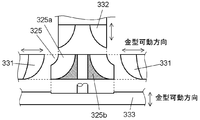
- FIG. 12A is a plan view showing a mold operation at the time of molding a resin inducer 325 of a conventional impeller 321, and FIG. 12B is a side view thereof.
- the resin inducer 325 is created by resin molding using a side slide mold 331 that slides radially in the outer circumferential direction of the blade portion 325a.
- the molding die is composed of the same number of side slide dies 331 as the number of blades of the blade portion 325a, and the upper slide die 332 and the lower slide die 333.
- the number of blade portions 325a and sheet metal blades 324 of the resin inducer 325 be six. It is said that. However, depending on the air volume and the number of rotations, the air blowing efficiency may be improved when the number of blade portions 325a and sheet metal blades 324 is more than six.
- high-frequency sound which is a kind of noise generated by the electric blower
- the number of blades of the impeller 321 exceeds six and the end surface on the front shroud 323 side of a certain blade portion 325a is adjacent to Molding is difficult when the end surface of the blade portion 325a on the sheet metal blade 324 side overlaps each other when viewed from the top or side surface.
- the present invention provides an impeller of an electric blower that can easily increase the number of blades of an inducer and increase the air blowing efficiency and is low in noise, and an electric blower and a vacuum cleaner provided with the impeller.
- An impeller according to the present invention is sandwiched between a front shroud having a first opening in the center, a rear shroud spaced from the front shroud, a front shroud and a rear shroud, and the center of the rear shroud.
- a plurality of blades extending from the outer periphery toward the outer periphery, and an inducer provided at the center of the rear shroud.
- the inducer includes an upper inducer provided on the front shroud side and a lower inducer provided on the rear shroud side.
- the impeller of the present invention it is possible to easily increase the number of blades of the inducer, improve the air blowing efficiency, and realize low noise.
- FIG. 1 is a partial cross-sectional view illustrating a configuration of an electric blower including an impeller according to a first embodiment of the present invention.
- FIG. 2 is a perspective view with a part cut away showing the configuration of the impeller in the first embodiment of the present invention.
- FIG. 3 is an exploded perspective view showing the configuration of the impeller in the first embodiment of the present invention.
- FIG. 4 is a cross-sectional view showing the configuration of the impeller in the first embodiment of the present invention.
- FIG. 5A is a plan view showing a mold configuration of a lower inducer of the impeller according to the first embodiment of the present invention.
- FIG. 5B is a side view showing a mold configuration of the lower inducer of the impeller according to the first embodiment of the present invention.
- FIG. 5A is a plan view showing a mold configuration of a lower inducer of the impeller according to the first embodiment of the present invention.
- FIG. 5B is a side view showing a mold configuration of the lower inducer of
- FIG. 6A is a plan view of an upper inducer of the impeller according to the first embodiment of the present invention.
- FIG. 6B is a side view showing a mold configuration of the upper inducer of the impeller according to the first embodiment of the present invention.
- FIG. 7 is a cross-sectional view showing the configuration of the impeller in the second embodiment of the present invention.
- FIG. 8 is a cross-sectional view showing the configuration of the impeller in the third embodiment of the present invention.
- FIG. 9 is a cross-sectional view showing the configuration of the impeller in the fourth embodiment of the present invention.
- FIG. 10: is a figure which shows the outline
- FIG. 10 is a figure which shows the outline
- FIG. 11 is a perspective view with a part cut away for explaining the configuration of a conventional impeller.
- FIG. 12A is a plan view showing a mold operation during resin-made inducer molding of a conventional impeller.
- FIG. 12B is a side view showing a mold operation during resin-induced inducer molding of a conventional impeller.
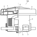
- FIG. 1 is a partial cross-sectional view illustrating a configuration of an electric blower 100 including an impeller 1 according to a first embodiment of the present invention.
- FIG. 2 is a perspective view in which a part of the configuration of the impeller 1 according to the first embodiment of the present invention is cut away.
- FIG. 3 is an exploded perspective view showing the configuration of the impeller 1 according to the first embodiment of the present invention.
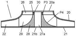
- FIG. 4 is a cross-sectional view showing the configuration of the impeller 1 according to the first embodiment of the present invention.
- the electric blower 100 includes an impeller 1, an air guide 2, a fan case 3, an electric motor 4, and an anti-load side bracket 6.
- the impeller 1 generates an air flow (suction air).
- the air guide 2 is disposed to face the outer periphery of the impeller 1 and rectifies the airflow discharged from the impeller 1.
- the fan case 3 contains the impeller 1 and the air guide 2.
- the electric motor 4 rotationally drives the impeller 1.
- the anti-load side bracket 6 is provided on the outer periphery of the electric motor 4, and the fan case 3 is attached in an airtight manner.
- the impeller 1 is pivotally supported on the shaft 5 of the electric motor 4.
- the anti-load side bracket 6 is provided with an exhaust opening 7 for exhausting air sucked by the impeller 1.
- the impeller 1 includes a front shroud 20, a rear shroud 21, a plurality of blades 22, and an inducer 23.
- the front shroud 20 is provided with an air inlet 20a which is a first opening at the center.
- the rear shroud 21 is disposed at a distance from the front shroud 20.
- the plurality of blades 22 are sandwiched by the front shroud 20 and the rear shroud 21 and extend from the center of the rear shroud 21 toward the outer periphery of the rear shroud 21.
- the inducer 23 is provided at the center of the rear shroud 21. The inducer 23 is sandwiched between the front shroud 20 and the rear shroud 21.
- a plurality of fitting protrusions 22a and 22b are provided on the surface of the blade 22 that contacts the front shroud 20 and the rear shroud 21, respectively. Further, the front shroud 20 and the rear shroud 21 are provided with a plurality of fitting holes 20b and 21a that are fitted to the fitting protrusions 22a and 22b, respectively.
- the blade 22 is attached to the front shroud 20 and the rear shroud 21 by inserting the fitting protrusions 22a and 22b into the fitting holes 20b and 21a, respectively, and caulking.
- the inducer 23 is a surface parallel to the rear surface shroud 21, that is, a surface perpendicular to the shaft 5 of the electric motor 4, and is provided on the upper shroud 20 side and the rear surface shroud 21 side. It is divided into a lower inducer 27. As a result, when the inducer 23 is sandwiched between the front shroud 20 and the rear shroud 21, a force vector applied to the inducer 23 is evenly applied to the split surface between the upper inducer 24 and the lower inducer 27. For this reason, the inducer 23 can be more reliably held by the front shroud 20 and the rear shroud 21.
- the inducer 23 has an end face P1 on the front shroud 20 side of a blade part of an inducer 23 and an end face P2 on the blade 22 side of a blade part of an adjacent inducer 23 when viewed from the upper surface or side surface.
- the shapes overlap each other. That is, it is difficult to mold by the conventional inducer molding method.
- the upper inducer 24 includes a ring portion 25 having a second opening 25 a in the center, and a plurality of pieces extending from the ring portion 25 toward the outer peripheral side of the inducer 23.
- the first blade portion 26 is configured.
- the lower inducer 27 includes a base portion 28, a plurality of second blade portions 29, and a shaft portion 30.
- the base portion 28 is attached to the rear shroud 21 and has a conical shape.
- the plurality of second blade portions 29 extend from the center portion of the base portion 28 toward the outer peripheral side of the base portion 28.
- the shaft portion 30 extends from the center portion of the base portion 28 toward the upper inducer 24 and is fitted to the ring portion 25.
- a third opening 27 a and a fourth opening 21 b that are fitted to the shaft 5 of the electric motor 4 are provided at the center of the lower inducer 27 and the center of the rear shroud 21, respectively. ing.
- the impeller 1 is rotationally driven by the electric motor 4 when the shaft 5 of the electric motor 4 is inserted into and supported by the third opening 27a and the fourth opening 21b.
- a convex portion 30a is formed at the end of the shaft portion 30 of the lower inducer 27 on the base portion 28 side. Further, a concave portion 25b that fits with the convex portion 30a is formed at an end portion of the ring portion 25 of the upper inducer 24 on the lower inducer 27 side. The upper inducer 24 is positioned and attached to the lower inducer 27 by the convex portion 30a and the concave portion 25b.
- the upper inducer 24 and the lower inducer 27 constitute an inducer 23.
- the ring portion 25 of the upper inducer 24 is fitted to the shaft portion 30 of the lower inducer 27 and positioned and attached to the lower inducer 27.
- the upper inducer 24 and the lower inducer 27 can be more reliably held with a simple configuration.
- first blade portion 26 of the upper inducer 24 and the second blade portion 29 of the lower inducer 27 constitute a blade portion of the inducer 23.
- the ring portion 25 of the upper inducer 24 and the shaft portion 30 of the lower inducer 27 are the ring portion 25 of the upper inducer 24 in a state where the upper inducer 24 is attached to the lower inducer 27.
- the outer peripheral surface P3 and the front shroud 20 side surface P4 of the base portion 28 of the lower inducer 27 are formed to be the same surface.
- the number of first blade portions 26 of the upper inducer 24, the number of second blade portions 29 of the lower inducer 27, and the number of blades 22 are determined based on the air volume and impeller of the electric blower 100. From the viewpoint of the number of rotations of 1, the number is nine.
- the front shroud 20, the rear shroud 21, and the blade 22 are made of metal, and the inducer 23 is made of resin.
- FIG. 5A is a plan view showing a mold configuration of the lower inducer 27 of the impeller 1 according to the first embodiment of the present invention.
- FIG. 5B is a side view showing the mold configuration.
- FIG. 6A is a plan view of the upper inducer 24 of the impeller 1 according to the first embodiment of the present invention.
- FIG. 6B is a side view showing a mold configuration of the upper inducer 24 of the impeller 1 according to the first embodiment of the present invention.
- the mold of the lower inducer 27 is configured at a 40-degree angular interval, a slide mold 31 arranged in nine directions, and a core 32 that molds the lower inducer 27 from above. And a cavity 33 for molding the lower inducer 27 from below.
- an end surface P1 on the front shroud 20 side of a blade portion of an inducer 23 and an end surface P2 on the blade 22 side of a blade portion of an adjacent inducer 23 overlap each other when viewed from the top or side.
- it is divided into two parts, an upper inducer 24 and a lower inducer 27, and has a shape that can be molded by the above-described mold structure.
- the mold of the upper inducer 24 includes a core 42 that molds the upper inducer 24 from above and a cavity 43 that molds the upper inducer 24 from below. Yes.
- the inducer 23 can be molded by dividing it into two parts, an upper inducer 24 and a lower inducer 27. By combining these two parts when the impeller 1 is assembled, a multi-blade shape can be realized. For this reason, the inducer 23 can be easily multi-bladed, the air blowing efficiency of the electric blower 100 can be improved, and noise reduction can be realized.
- the inducer 23 is sandwiched between the front shroud 20 and the rear shroud 21, the inducer 23 can be reliably held with a simple configuration. Further, as described above, it is possible to easily realize the multi-blade of the inducer 23. Therefore, by using the impeller 1 of the present embodiment, it is possible to improve the air blowing efficiency of the electric blower 100 and to reduce noise.
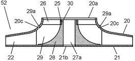
- FIG. 7 is a cross-sectional view showing the configuration of the impeller 51 in the second embodiment of the present invention.
- the front shroud 20 has a front shroud 20 of the first blade portion 26 and the second blade portion 29 at a position where it abuts with the first blade portion 26 and the second blade portion 29.
- a groove 34 having substantially the same shape and the same width as the abutting end surface is provided over the entire circumference.
- the inducer 23 can be more securely held on the front shroud 20 with a simple configuration. Further, warp deformation of the first blade portion 26 and the second blade portion 29 caused by internal stress or the like generated when the inducer 23 is molded can be corrected by the groove portion 34 of the front shroud 20.
- the impeller 51 of the present embodiment it is possible to easily realize the multi-blade of the inducer 23. Therefore, the air blowing efficiency of the electric blower 100 can be improved and noise reduction can be realized.
- FIG. 8 is a cross-sectional view showing the configuration of the impeller 52 in the third embodiment of the present invention.
- symbol is attached
- the second blade 29 is provided with a protrusion 29 a extending from the end surface of the second blade 29 that contacts the front shroud 20 toward the front shroud 20.
- a hole 20c that fits with the protrusion 29a is provided at a position facing the protrusion 29a of the front shroud 20.
- the inducer 23 is fixed to the front shroud 20 by inserting and welding the projections 29a of the second blade portion 29 into the holes 20c of the front shroud 20.
- the inducer 23 can be more reliably held on the front shroud 20 with a simple configuration, it is possible to easily realize a multi-blade of the inducer 23. Thereby, also by using the impeller 52 of the present embodiment, it is possible to improve the blowing efficiency of the electric blower 100 and to reduce the noise.
- the protruding portion 29 a may be provided on the first blade portion 26, or may be provided on both the first blade portion 26 and the second blade portion 29.
- the inducer 23 can be held on the front shroud 20 more reliably with a simple configuration, so that the increase in the number of the blades of the inducer 23 can be easily realized. Therefore, the air blowing efficiency of the electric blower 100 can be improved and noise reduction can be realized.
- FIG. 9 is a cross-sectional view showing the configuration of the impeller 53 according to the fourth embodiment of the present invention.
- FIG. 9 shows a cross-sectional configuration near the center of the impeller 53.
- a claw portion 30 b that engages with an end surface of the ring portion 25 of the upper inducer 24 on the front shroud 20 side is provided at the end portion of the shaft portion 30 of the lower inducer 27 on the front shroud 20 side. It has been.
- the upper inducer 24 can be more securely held in the axial direction with respect to the lower inducer 27, it is possible to easily realize the multi-blade of the inducer 23.
- the impeller 53 of the present embodiment it is possible to improve the blowing efficiency of the electric blower 100 and to reduce noise.
- FIG. 10 is a diagram showing an outline of the electric vacuum cleaner 200 according to the fifth embodiment of the present invention. Also in the present embodiment, the same or corresponding components as those described in the first to fourth embodiments are denoted by the same reference numerals, and the description thereof is omitted.
- the electric vacuum cleaner 200 includes a cleaner body 201, a suction tool 202 that sucks dust on the surface to be cleaned, a hose 203 having one end connected to the cleaner body 201, and a hose 203 at one end.
- the other end of the extension pipe 204 is connected to the suction tool 202.
- a hand operation unit 205 is provided at the end of the hose 203 on the extension tube 204 side.
- the vacuum cleaner main body 201 includes any one of the impellers 1, 51, 52, and 53 described in the first to fourth embodiments, and the electric blower 100 that generates suction air.
- the dust collector 206 is disposed upstream of the electric blower 100 and collects dust.
- the electric blower 100 When the user holds the hand operating unit 205 and starts the operation of the electric vacuum cleaner 200, the electric blower 100 generates suction air and generates suction power. When the user moves the suction tool 202 on the surface to be cleaned in this state, dust on the surface to be cleaned is sucked together with air from the suction tool 202.
- the air after the dust is separated is sucked by the electric blower 100, passes through the electric blower 100, passes through the cleaner main body 201, and is discharged to the outside of the cleaner main body 201.
- the vacuum cleaner 200 incorporates the electric blower 100 having the impellers 1, 51, 52, and 53 described in the first to fourth embodiments described above.
- a vacuum cleaner with high performance and low noise can be realized. Therefore, the user can clean comfortably by using the electric vacuum cleaner 200 in the present embodiment.
- the impeller of the present invention is not limited to the configuration of the impellers 1, 51, 52, and 53 described in the above embodiments.
- the number of first blade portions 26, the number of second blade portions 29, and the number of blades 22 are nine.
- the impeller of the present invention is not limited to this configuration.
- the number of first blade portions 26, the number of second blade portions 29, and the number of blades 22 can be suitably determined from the viewpoint of the air volume of the electric blower and the rotational speed of the impeller.
- the blades of the inducer can be easily multi-bladed, and the blowing efficiency can be improved. Therefore, the suction performance of the electric blower can be improved and noise reduction can be realized.
- the suction power of the vacuum cleaner can be improved, and a low-noise vacuum cleaner can be realized. Therefore, the present invention is useful as household electrical appliances, industrial equipment, and the like that use an electric blower.
Abstract
Disclosed is an impeller (1) provided with a front shroud (20) having a first opening (20a) on the center, a rear shroud (21) spaced from the front shroud (20), a plurality of blades (22) which are sandwiched by the front shroud (20) and the rear shroud (21) and which extend from the center toward the outer periphery of the rear shroud (21), and an inducer (23) provided on the center of the rear shroud (21). The inducer (23) is comprised of an upper inducer (24) provided on the front shroud (20) side, and a lower inducer (27) provided on the rear shroud (21) side.
Description
本発明は、インペラ、ならびに、それを備えた電動送風機および電気掃除機に関する。
The present invention relates to an impeller, and an electric blower and a vacuum cleaner provided with the impeller.
従来、電気掃除機に使用される電動送風機のインペラにおいて、電動送風機の送風性能(吸込み性能)を向上させる検討がされてきた。例えば、前面シュラウド、後面シュラウド、ブレードおよびインデューサを備え、インデューサの羽根部およびブレードが、複数枚設けられた構成が提案されている(例えば、特許文献1を参照)。
Conventionally, in an impeller of an electric blower used for a vacuum cleaner, studies have been made to improve the blowing performance (suction performance) of the electric blower. For example, a configuration in which a front shroud, a rear shroud, a blade, and an inducer are provided and a plurality of blades and blades of the inducer are provided has been proposed (see, for example, Patent Document 1).
図11は、このような従来のインペラの構成について説明するための一部を切り欠いた斜視図である。図11に示すように、インペラ321は、後面シュラウド322と、前面シュラウド323と、板金製ブレード324と、樹脂製インデューサ325とを備えている。後面シュラウド322は板金製である。前面シュラウド323は、後面シュラウド322と間隔を置いて配置されており、中央に吸気口323aが設けられている。複数枚の板金製ブレード324は、後面シュラウド322および前面シュラウド323で挟持されている。樹脂製インデューサ325は、吸気口323aに対応して設けられている。
FIG. 11 is a perspective view with a part cut away for explaining the configuration of such a conventional impeller. As shown in FIG. 11, the impeller 321 includes a rear shroud 322, a front shroud 323, a sheet metal blade 324, and a resin inducer 325. The rear shroud 322 is made of sheet metal. The front shroud 323 is disposed at a distance from the rear shroud 322, and an air inlet 323a is provided at the center. The plurality of sheet metal blades 324 are sandwiched between the rear shroud 322 and the front shroud 323. The resin inducer 325 is provided corresponding to the air inlet 323a.
樹脂製インデューサ325は、円錐状のハブ325bと、ハブ325b上に形成される羽根部325aとから構成されている。吸気口323aから板金製ブレード324側へ流れる空気を整流するため、羽根部325aの形状は三次元曲面を有する形状となっている。
The resin inducer 325 includes a conical hub 325b and a blade portion 325a formed on the hub 325b. In order to rectify the air flowing from the intake port 323a to the sheet metal blade 324 side, the shape of the blade portion 325a has a three-dimensional curved surface.
図12Aは、従来のインペラ321の樹脂製インデューサ325成型時の金型動作を示す平面図であり、図12Bは、その側面図である。
FIG. 12A is a plan view showing a mold operation at the time of molding a resin inducer 325 of a conventional impeller 321, and FIG. 12B is a side view thereof.
図12Aおよび図12Bに示すように、樹脂製インデューサ325は、羽根部325aの外周方向へ放射状にスライドする側方スライド金型331を用いた、樹脂成型加工によって作成される。成型金型は、羽根部325aの羽根の数と同数の側方スライド金型331、ならびに、上方スライド金型332および下方スライド金型333から構成されている。
12A and 12B, the resin inducer 325 is created by resin molding using a side slide mold 331 that slides radially in the outer circumferential direction of the blade portion 325a. The molding die is composed of the same number of side slide dies 331 as the number of blades of the blade portion 325a, and the upper slide die 332 and the lower slide die 333.
このような従来の電動送風機のインペラ321において、送風効率(吸込み性能)を向上させるには、樹脂製インデューサ325の羽根部325aおよび板金製ブレード324の枚数を6枚とすることが最適であるとされている。しかしながら、風量および回転数によっては、羽根部325aおよび板金製ブレード324の枚数が6枚を超える多翼である方が、送風効率が向上する場合がある。
In such an impeller 321 of a conventional electric blower, in order to improve the blowing efficiency (suction performance), it is optimal that the number of blade portions 325a and sheet metal blades 324 of the resin inducer 325 be six. It is said that. However, depending on the air volume and the number of rotations, the air blowing efficiency may be improved when the number of blade portions 325a and sheet metal blades 324 is more than six.
また、一般的に、電動送風機が発する騒音の一種である高周波音は、インペラ321の羽根の枚数(羽根部325aおよび板金製ブレード324の枚数)と、回転数との積の整数倍の周波数で顕著に発生することが知られている。このため、羽根の枚数が少ない場合には、電動送風機が発する高周波音の周波数が、使用者に聞こえやすい周波数帯域となり、耳障りな音として聞こえ、不快感を与える場合がある。
In general, high-frequency sound, which is a kind of noise generated by the electric blower, has a frequency that is an integral multiple of the product of the number of blades of the impeller 321 (the number of blade portions 325a and sheet metal blades 324) and the number of rotations. It is known to occur significantly. For this reason, when the number of blades is small, the frequency of the high-frequency sound generated by the electric blower becomes a frequency band that can be easily heard by the user, and may be heard as an irritating sound, which may cause discomfort.
この高周波音を低減する方法として、インペラ321の羽根の枚数を増やすことにより、高周波音の周波数を使用者に聞こえやすい周波数帯域から遠ざけることで、耳障りで不快な音を低減する方法が考えられている。
As a method of reducing the high frequency sound, there is a method of reducing the frequency of the high frequency sound away from the frequency band where the user can easily hear by increasing the number of blades of the impeller 321, thereby reducing harsh and unpleasant sound. Yes.
しかしながら、上述した従来の電動送風機のインペラ321の樹脂性インデューサ325の成型方法では、インペラ321の羽根の枚数が6枚を超え、かつ、ある羽根部325aの前面シュラウド323側の端面と、隣接する羽根部325aの板金製ブレード324側の端面とが、上面または側面から見た場合に互いに重なり合う場合には、成型が困難である。
However, in the molding method of the resinous inducer 325 of the impeller 321 of the conventional electric blower described above, the number of blades of the impeller 321 exceeds six and the end surface on the front shroud 323 side of a certain blade portion 325a is adjacent to Molding is difficult when the end surface of the blade portion 325a on the sheet metal blade 324 side overlaps each other when viewed from the top or side surface.
本発明は、インデューサの羽根を簡単に多翼化でき、送風効率を向上させるとともに、低騒音な電動送風機のインペラ、ならびに、それを備えた電動送風機および電気掃除機を提供するものである。
The present invention provides an impeller of an electric blower that can easily increase the number of blades of an inducer and increase the air blowing efficiency and is low in noise, and an electric blower and a vacuum cleaner provided with the impeller.
本発明のインペラは、中央部に第1の開口部を有する前面シュラウドと、前面シュラウドと間隔をおいて配置される後面シュラウドと、前面シュラウドおよび後面シュラウドによって挟持されており、後面シュラウドの中央部から外周に向かって伸びる複数枚のブレードと、後面シュラウドの中央部に設けられるインデューサとを備えている。インデューサは、前面シュラウド側に設けられた上部インデューサと、後面シュラウド側に設けられた下部インデューサとからなる。
An impeller according to the present invention is sandwiched between a front shroud having a first opening in the center, a rear shroud spaced from the front shroud, a front shroud and a rear shroud, and the center of the rear shroud. A plurality of blades extending from the outer periphery toward the outer periphery, and an inducer provided at the center of the rear shroud. The inducer includes an upper inducer provided on the front shroud side and a lower inducer provided on the rear shroud side.
本発明のインペラによれば、インデューサを簡単に多翼化することができ、送風効率を向上させることができるとともに、低騒音化を実現することができる。
According to the impeller of the present invention, it is possible to easily increase the number of blades of the inducer, improve the air blowing efficiency, and realize low noise.
以下、図面を参照しながら本発明の実施の形態について説明する。
Hereinafter, embodiments of the present invention will be described with reference to the drawings.
(第1の実施の形態)
本発明の第1の実施の形態におけるインペラ1およびそれを備えた電動送風機100について説明する。 (First embodiment)
Theimpeller 1 and the electric blower 100 including the impeller 1 according to the first embodiment of the present invention will be described.
本発明の第1の実施の形態におけるインペラ1およびそれを備えた電動送風機100について説明する。 (First embodiment)
The
図1は、本発明の第1の実施の形態におけるインペラ1を備えた電動送風機100の構成を示す一部断面図である。図2は、本発明の第1の実施の形態におけるインペラ1の構成を示す一部を切り欠いた斜視図である。図3は、本発明の第1の実施の形態におけるインペラ1の構成を示す分解斜視図である。また、図4は、本発明の第1の実施の形態におけるインペラ1の構成を示す断面図である。
FIG. 1 is a partial cross-sectional view illustrating a configuration of an electric blower 100 including an impeller 1 according to a first embodiment of the present invention. FIG. 2 is a perspective view in which a part of the configuration of the impeller 1 according to the first embodiment of the present invention is cut away. FIG. 3 is an exploded perspective view showing the configuration of the impeller 1 according to the first embodiment of the present invention. FIG. 4 is a cross-sectional view showing the configuration of the impeller 1 according to the first embodiment of the present invention.
図1に示すように、電動送風機100は、インペラ1、エアガイド2、ファンケース3、電動機4および反負荷側ブラケット6を備えている。
As shown in FIG. 1, the electric blower 100 includes an impeller 1, an air guide 2, a fan case 3, an electric motor 4, and an anti-load side bracket 6.
インペラ1は、気流(吸引風)を発生させる。エアガイド2は、インペラ1の外周に対向して配置されており、インペラ1から放出された気流を整流する。ファンケース3は、インペラ1およびエアガイド2を内包している。電動機4は、インペラ1を回転駆動する。反負荷側ブラケット6は、電動機4の外周に設けられ、ファンケース3が気密に取付けられている。
The impeller 1 generates an air flow (suction air). The air guide 2 is disposed to face the outer periphery of the impeller 1 and rectifies the airflow discharged from the impeller 1. The fan case 3 contains the impeller 1 and the air guide 2. The electric motor 4 rotationally drives the impeller 1. The anti-load side bracket 6 is provided on the outer periphery of the electric motor 4, and the fan case 3 is attached in an airtight manner.
また、インペラ1は、電動機4の軸5に軸支されている。反負荷側ブラケット6には、インペラ1により吸引された空気を排気する排気開口部7が設けられている。
The impeller 1 is pivotally supported on the shaft 5 of the electric motor 4. The anti-load side bracket 6 is provided with an exhaust opening 7 for exhausting air sucked by the impeller 1.
図2~図4に示すように、インペラ1は、前面シュラウド20、後面シュラウド21、複数枚のブレード22およびインデューサ23を備えている。
2 to 4, the impeller 1 includes a front shroud 20, a rear shroud 21, a plurality of blades 22, and an inducer 23.
前面シュラウド20は、中央部に第1の開口部である吸気口20aが設けられている。後面シュラウド21は、前面シュラウド20と間隔を置いて配置されている。複数枚のブレード22は、前面シュラウド20および後面シュラウド21によって挟持され、後面シュラウド21の中央部から後面シュラウド21の外周に向かって伸びている。インデューサ23は、後面シュラウド21の中央部に設けられている。インデューサ23は、前面シュラウド20および後面シュラウド21により挟持されている。
The front shroud 20 is provided with an air inlet 20a which is a first opening at the center. The rear shroud 21 is disposed at a distance from the front shroud 20. The plurality of blades 22 are sandwiched by the front shroud 20 and the rear shroud 21 and extend from the center of the rear shroud 21 toward the outer periphery of the rear shroud 21. The inducer 23 is provided at the center of the rear shroud 21. The inducer 23 is sandwiched between the front shroud 20 and the rear shroud 21.
ブレード22の前面シュラウド20および後面シュラウド21に当接する面には、それぞれ複数の嵌合突起部22a、22bが設けられている。また、前面シュラウド20および後面シュラウド21には、嵌合突起部22a、22bそれぞれと嵌合する、複数の嵌合孔部20b、21aが設けられている。ブレード22は、嵌合突起部22a、22bを嵌合孔部20b、21aそれぞれに挿入し、加締め加工することにより、前面シュラウド20および後面シュラウド21に取付けられる。
A plurality of fitting protrusions 22a and 22b are provided on the surface of the blade 22 that contacts the front shroud 20 and the rear shroud 21, respectively. Further, the front shroud 20 and the rear shroud 21 are provided with a plurality of fitting holes 20b and 21a that are fitted to the fitting protrusions 22a and 22b, respectively. The blade 22 is attached to the front shroud 20 and the rear shroud 21 by inserting the fitting protrusions 22a and 22b into the fitting holes 20b and 21a, respectively, and caulking.
インデューサ23は、後面シュラウド21に平行な面、すなわち、電動機4の軸5に対して垂直な面で、前面シュラウド20側に設けられた上部インデューサ24と、後面シュラウド21側に設けられた下部インデューサ27とに分割されている。これにより、インデューサ23が、前面シュラウド20および後面シュラウド21によって挟持される際、インデューサ23にかかる力のベクトルが、上部インデューサ24と下部インデューサ27との分割面に均等に加わる。このため、前面シュラウド20および後面シュラウド21によって、インデューサ23をより確実に保持することができる。
The inducer 23 is a surface parallel to the rear surface shroud 21, that is, a surface perpendicular to the shaft 5 of the electric motor 4, and is provided on the upper shroud 20 side and the rear surface shroud 21 side. It is divided into a lower inducer 27. As a result, when the inducer 23 is sandwiched between the front shroud 20 and the rear shroud 21, a force vector applied to the inducer 23 is evenly applied to the split surface between the upper inducer 24 and the lower inducer 27. For this reason, the inducer 23 can be more reliably held by the front shroud 20 and the rear shroud 21.
また、インデューサ23は、あるインデューサ23の羽根部の前面シュラウド20側の端面P1と、隣接するインデューサ23の羽根部のブレード22側の端面P2が、上面または側面から見た場合に、互いに重なり合う形状となっている。つまり、従来のインデューサの成型方法では成型が困難な形状となっている。
The inducer 23 has an end face P1 on the front shroud 20 side of a blade part of an inducer 23 and an end face P2 on the blade 22 side of a blade part of an adjacent inducer 23 when viewed from the upper surface or side surface. The shapes overlap each other. That is, it is difficult to mold by the conventional inducer molding method.
図3および図4に示すように、上部インデューサ24は、中央部に第2の開口部25aを有するリング部25と、リング部25からインデューサ23の外周側に向かって伸びる、複数枚の第1の羽根部26とから構成されている。また、下部インデューサ27は、土台部28と、複数枚の第2の羽根部29と、軸部30とから構成されている。土台部28は、後面シュラウド21に取付けられ、円錐状である。複数枚の第2の羽根部29は、土台部28の中央部から土台部28の外周側に向かって伸びている。軸部30は、土台部28の中央部から上部インデューサ24側に向かって伸びるとともに、リング部25と嵌合している。
As shown in FIGS. 3 and 4, the upper inducer 24 includes a ring portion 25 having a second opening 25 a in the center, and a plurality of pieces extending from the ring portion 25 toward the outer peripheral side of the inducer 23. The first blade portion 26 is configured. The lower inducer 27 includes a base portion 28, a plurality of second blade portions 29, and a shaft portion 30. The base portion 28 is attached to the rear shroud 21 and has a conical shape. The plurality of second blade portions 29 extend from the center portion of the base portion 28 toward the outer peripheral side of the base portion 28. The shaft portion 30 extends from the center portion of the base portion 28 toward the upper inducer 24 and is fitted to the ring portion 25.
図4に示すように、下部インデューサ27の中心部および後面シュラウド21の中心部には、それぞれ電動機4の軸5と嵌合する第3の開口部27aおよび第4の開口部21bが設けられている。インペラ1は、電動機4の軸5が、第3の開口部27aおよび第4の開口部21bに挿入され、軸支されることで、電動機4によって回転駆動される。
As shown in FIG. 4, a third opening 27 a and a fourth opening 21 b that are fitted to the shaft 5 of the electric motor 4 are provided at the center of the lower inducer 27 and the center of the rear shroud 21, respectively. ing. The impeller 1 is rotationally driven by the electric motor 4 when the shaft 5 of the electric motor 4 is inserted into and supported by the third opening 27a and the fourth opening 21b.
図3に示すように、下部インデューサ27の軸部30の土台部28側の端部には、凸部30aが形成されている。また、上部インデューサ24のリング部25の下部インデューサ27側の端部には、凸部30aと嵌合する凹部25bが形成されている。上部インデューサ24は、凸部30aおよび凹部25bにより下部インデューサ27に対して位置決めされ、取付けられる。
As shown in FIG. 3, a convex portion 30a is formed at the end of the shaft portion 30 of the lower inducer 27 on the base portion 28 side. Further, a concave portion 25b that fits with the convex portion 30a is formed at an end portion of the ring portion 25 of the upper inducer 24 on the lower inducer 27 side. The upper inducer 24 is positioned and attached to the lower inducer 27 by the convex portion 30a and the concave portion 25b.
上部インデューサ24および下部インデューサ27は、インデューサ23を構成している。上部インデューサ24のリング部25が、下部インデューサ27の軸部30に嵌合して、下部インデューサ27に対して位置決めされ、取付けられる。これにより、上部インデューサ24と下部インデューサ27とを簡単な構成で、より確実に保持させることができる。
The upper inducer 24 and the lower inducer 27 constitute an inducer 23. The ring portion 25 of the upper inducer 24 is fitted to the shaft portion 30 of the lower inducer 27 and positioned and attached to the lower inducer 27. Thereby, the upper inducer 24 and the lower inducer 27 can be more reliably held with a simple configuration.
また、上部インデューサ24の第1の羽根部26と下部インデューサ27の第2の羽根部29とにより、インデューサ23の羽根部が構成されている。
Further, the first blade portion 26 of the upper inducer 24 and the second blade portion 29 of the lower inducer 27 constitute a blade portion of the inducer 23.
図4に示すように、上部インデューサ24のリング部25および下部インデューサ27の軸部30は、上部インデューサ24が下部インデューサ27に取付けられた状態において、上部インデューサ24のリング部25の外周側の面P3と下部インデューサ27の土台部28の前面シュラウド20側の面P4とが同一面となるように形成されている。
As shown in FIG. 4, the ring portion 25 of the upper inducer 24 and the shaft portion 30 of the lower inducer 27 are the ring portion 25 of the upper inducer 24 in a state where the upper inducer 24 is attached to the lower inducer 27. The outer peripheral surface P3 and the front shroud 20 side surface P4 of the base portion 28 of the lower inducer 27 are formed to be the same surface.
本実施の形態においては、上部インデューサ24の第1の羽根部26の枚数、下部インデューサ27の第2の羽根部29の枚数、および、ブレード22の枚数を、電動送風機100の風量およびインペラ1の回転数の観点から、9枚としている。
In the present embodiment, the number of first blade portions 26 of the upper inducer 24, the number of second blade portions 29 of the lower inducer 27, and the number of blades 22 are determined based on the air volume and impeller of the electric blower 100. From the viewpoint of the number of rotations of 1, the number is nine.
また、本実施の形態においては、前面シュラウド20、後面シュラウド21およびブレード22は金属で形成されており、インデューサ23は樹脂で形成されている。
In the present embodiment, the front shroud 20, the rear shroud 21, and the blade 22 are made of metal, and the inducer 23 is made of resin.
以上のように構成されたインデューサ23の成型方法について説明する。
A method of forming the inducer 23 configured as described above will be described.
図5Aは、本発明の第1の実施の形態におけるインペラ1の下部インデューサ27の金型構成を示す平面図である。図5Bは、その金型構成を示す側面図である。図6Aは、本発明の第1の実施の形態におけるインペラ1の上部インデューサ24の平面図である。また、図6Bは、本発明の第1の実施の形態におけるインペラ1の上部インデューサ24の金型構成を示す側面図である。
FIG. 5A is a plan view showing a mold configuration of the lower inducer 27 of the impeller 1 according to the first embodiment of the present invention. FIG. 5B is a side view showing the mold configuration. FIG. 6A is a plan view of the upper inducer 24 of the impeller 1 according to the first embodiment of the present invention. FIG. 6B is a side view showing a mold configuration of the upper inducer 24 of the impeller 1 according to the first embodiment of the present invention.
図5Aおよび図5Bに示すように、下部インデューサ27の金型は、40度角間隔で構成され、9方向に配置されたスライド金型31と、下部インデューサ27を上方から成型するコア32と、下部インデューサ27を下方から成型するキャビティ33とから構成されている。
As shown in FIGS. 5A and 5B, the mold of the lower inducer 27 is configured at a 40-degree angular interval, a slide mold 31 arranged in nine directions, and a core 32 that molds the lower inducer 27 from above. And a cavity 33 for molding the lower inducer 27 from below.
インデューサ23は、あるインデューサ23の羽根部の前面シュラウド20側の端面P1と、隣接するインデューサ23の羽根部のブレード22側の端面P2が、上面または側面から見て互いに重なり合っている。しかし、上部インデューサ24と下部インデューサ27との2部品に分割して、上述した金型構造により、成型可能な形状となっている。
In the inducer 23, an end surface P1 on the front shroud 20 side of a blade portion of an inducer 23 and an end surface P2 on the blade 22 side of a blade portion of an adjacent inducer 23 overlap each other when viewed from the top or side. However, it is divided into two parts, an upper inducer 24 and a lower inducer 27, and has a shape that can be molded by the above-described mold structure.
また、図6Aおよび図6Bに示すように、上部インデューサ24の金型は、上部インデューサ24を上方から成型するコア42と、上部インデューサ24を下方から成型するキャビティ43とから構成されている。
As shown in FIGS. 6A and 6B, the mold of the upper inducer 24 includes a core 42 that molds the upper inducer 24 from above and a cavity 43 that molds the upper inducer 24 from below. Yes.
上述したように、インデューサ23は、従来の構成および成型方法では多翼化させることが困難である。しかしながら、本実施の形態に示すように、インデューサ23を上部インデューサ24と下部インデューサ27との2部品に分割することによって、それぞれが成型可能となる。インペラ1の組立て時に、これら2部品を組み合わせることで、多翼化形状を実現することが可能となる。このため、インデューサ23を簡単に多翼化することができ、電動送風機100の送風効率を向上させることができるとともに、低騒音化を実現することができる。
As described above, it is difficult to increase the number of blades of the inducer 23 by the conventional configuration and molding method. However, as shown in the present embodiment, the inducer 23 can be molded by dividing it into two parts, an upper inducer 24 and a lower inducer 27. By combining these two parts when the impeller 1 is assembled, a multi-blade shape can be realized. For this reason, the inducer 23 can be easily multi-bladed, the air blowing efficiency of the electric blower 100 can be improved, and noise reduction can be realized.
また、インデューサ23は、前面シュラウド20と後面シュラウド21とで挟持されているため、インデューサ23を簡単な構成で確実に保持することができる。また、上述のように、インデューサ23の多翼化を容易に実現することができる。よって、本実施の形態のインペラ1を用いることにより、電動送風機100の送風効率を向上させることができるとともに、低騒音化を実現することができる。
Moreover, since the inducer 23 is sandwiched between the front shroud 20 and the rear shroud 21, the inducer 23 can be reliably held with a simple configuration. Further, as described above, it is possible to easily realize the multi-blade of the inducer 23. Therefore, by using the impeller 1 of the present embodiment, it is possible to improve the air blowing efficiency of the electric blower 100 and to reduce noise.
(第2の実施の形態)
次に、本発明の第2の実施の形態におけるインペラ51について説明する。 (Second Embodiment)
Next, theimpeller 51 in the second embodiment of the present invention will be described.
次に、本発明の第2の実施の形態におけるインペラ51について説明する。 (Second Embodiment)
Next, the
図7は、本発明の第2の実施の形態におけるインペラ51の構成を示す断面図である。
FIG. 7 is a cross-sectional view showing the configuration of the impeller 51 in the second embodiment of the present invention.
なお、上述した第1の実施の形態のインペラ1の構成部品と同一または相当する構成部品については、同一の符号を付して、その説明を省略する。
In addition, about the component which is the same as that of the impeller 1 of 1st Embodiment mentioned above, or equivalent, attaches the same code | symbol and the description is abbreviate | omitted.
図7に示すように、前面シュラウド20の、第1の羽根部26および第2の羽根部29と当接する位置には、第1の羽根部26および第2の羽根部29の前面シュラウド20と当接する端面と、ほぼ同一形状かつ同一幅の溝部34が全周に亘って設けられている。
As shown in FIG. 7, the front shroud 20 has a front shroud 20 of the first blade portion 26 and the second blade portion 29 at a position where it abuts with the first blade portion 26 and the second blade portion 29. A groove 34 having substantially the same shape and the same width as the abutting end surface is provided over the entire circumference.
これにより、インデューサ23を簡単な構成で、より確実に前面シュラウド20に保持させることができる。また、インデューサ23の成型時に生じる内部応力等により発生する、第1の羽根部26および第2の羽根部29の反り変形を、前面シュラウド20の溝部34により矯正することができる。
Thereby, the inducer 23 can be more securely held on the front shroud 20 with a simple configuration. Further, warp deformation of the first blade portion 26 and the second blade portion 29 caused by internal stress or the like generated when the inducer 23 is molded can be corrected by the groove portion 34 of the front shroud 20.
本実施の形態のインペラ51を用いることによっても、インデューサ23の多翼化を容易に実現することができる。よって、電動送風機100の送風効率を向上させることができるとともに、低騒音化を実現することができる。
Also by using the impeller 51 of the present embodiment, it is possible to easily realize the multi-blade of the inducer 23. Therefore, the air blowing efficiency of the electric blower 100 can be improved and noise reduction can be realized.
(第3の実施の形態)
次に、本発明の第3の実施の形態におけるインペラ52について説明する。 (Third embodiment)
Next, animpeller 52 according to a third embodiment of the present invention will be described.
次に、本発明の第3の実施の形態におけるインペラ52について説明する。 (Third embodiment)
Next, an
図8は、本発明の第3の実施の形態におけるインペラ52の構成を示す断面図である。なお、上述した第1の実施の形態および第2の実施の形態のインペラ1、51と同一のまたは相当する構成部品については同一の符号を付し、その説明を省略する。
FIG. 8 is a cross-sectional view showing the configuration of the impeller 52 in the third embodiment of the present invention. In addition, the same code | symbol is attached | subjected about the component which is the same as that of the impellers 1 and 51 of 1st Embodiment mentioned above, and 2nd Embodiment, and equivalent, and the description is abbreviate | omitted.
図8に示すように、第2の羽根部29には、第2の羽根部29の前面シュラウド20と当接する端面から前面シュラウド20側に向かって伸びる突起部29aが設けられている。また、前面シュラウド20の突起部29aと相対する位置には、突起部29aと嵌合する孔部20cが設けられている。インデューサ23は、第2の羽根部29の突起部29aが前面シュラウド20の孔部20cに挿入され、溶着されることで前面シュラウド20に固定されている。
As shown in FIG. 8, the second blade 29 is provided with a protrusion 29 a extending from the end surface of the second blade 29 that contacts the front shroud 20 toward the front shroud 20. In addition, a hole 20c that fits with the protrusion 29a is provided at a position facing the protrusion 29a of the front shroud 20. The inducer 23 is fixed to the front shroud 20 by inserting and welding the projections 29a of the second blade portion 29 into the holes 20c of the front shroud 20.
これにより、インデューサ23を簡単な構成で、より確実に前面シュラウド20に保持させることができるため、インデューサ23の多翼化を容易に実現することができる。これにより、本実施の形態のインペラ52を用いることによっても、電動送風機100の送風効率を向上させることができるとともに、低騒音化を実現することができる。
Thereby, since the inducer 23 can be more reliably held on the front shroud 20 with a simple configuration, it is possible to easily realize a multi-blade of the inducer 23. Thereby, also by using the impeller 52 of the present embodiment, it is possible to improve the blowing efficiency of the electric blower 100 and to reduce the noise.
なお、本実施の形態においては、突起部29aが第2の羽根部29に設けられている構成について説明したが、本発明は、この構成に限定されるものではない。例えば、突起部29aは第1の羽根部26に設けられていてもよく、また、第1の羽根部26および第2の羽根部29の両方に設けられていてもよい。これらの構成においても、インデューサ23を簡単な構成で、より確実に前面シュラウド20に保持させることができるため、インデューサ23の多翼化を容易に実現することができる。よって、電動送風機100の送風効率を向上させることができるとともに、低騒音化を実現することができる。
In addition, in this Embodiment, although the structure in which the projection part 29a was provided in the 2nd blade | wing part 29 was demonstrated, this invention is not limited to this structure. For example, the protruding portion 29 a may be provided on the first blade portion 26, or may be provided on both the first blade portion 26 and the second blade portion 29. Even in these configurations, the inducer 23 can be held on the front shroud 20 more reliably with a simple configuration, so that the increase in the number of the blades of the inducer 23 can be easily realized. Therefore, the air blowing efficiency of the electric blower 100 can be improved and noise reduction can be realized.
(第4の実施の形態)
次に、本発明の第4の実施の形態におけるインペラ53について説明する。 (Fourth embodiment)
Next, animpeller 53 according to a fourth embodiment of the present invention will be described.
次に、本発明の第4の実施の形態におけるインペラ53について説明する。 (Fourth embodiment)
Next, an
図9は、本発明の第4の実施の形態におけるインペラ53の構成を示す断面図である。なお、図9においては、インペラ53の中央付近の断面構成を示している。
FIG. 9 is a cross-sectional view showing the configuration of the impeller 53 according to the fourth embodiment of the present invention. FIG. 9 shows a cross-sectional configuration near the center of the impeller 53.
本実施の形態においても、上述した第1の実施の形態~第3の実施の形態に示したインペラ1、51、52と同一または相当する構成部品については、同一の符号を付して、その説明を省略する。
Also in this embodiment, components that are the same as or equivalent to the impellers 1, 51, and 52 shown in the first to third embodiments are denoted by the same reference numerals, and Description is omitted.
図9に示すように、下部インデューサ27の軸部30の前面シュラウド20側の端部には、上部インデューサ24のリング部25の前面シュラウド20側の端面と係合する爪部30bが設けられている。
As shown in FIG. 9, a claw portion 30 b that engages with an end surface of the ring portion 25 of the upper inducer 24 on the front shroud 20 side is provided at the end portion of the shaft portion 30 of the lower inducer 27 on the front shroud 20 side. It has been.
これにより、上部インデューサ24を下部インデューサ27に対して、軸方向に、より確実に保持させることができるため、インデューサ23の多翼化を容易に実現することができる。これにより、本実施の形態のインペラ53を用いることによっても、電動送風機100の送風効率を向上させることができるとともに、低騒音化を実現することができる。
Thereby, since the upper inducer 24 can be more securely held in the axial direction with respect to the lower inducer 27, it is possible to easily realize the multi-blade of the inducer 23. Thereby, also by using the impeller 53 of the present embodiment, it is possible to improve the blowing efficiency of the electric blower 100 and to reduce noise.
(第5の実施の形態)
次に、本発明の第5の実施の形態における電気掃除機200について説明する。 (Fifth embodiment)
Next, thevacuum cleaner 200 in the 5th Embodiment of this invention is demonstrated.
次に、本発明の第5の実施の形態における電気掃除機200について説明する。 (Fifth embodiment)
Next, the
図10は、本発明の第5の実施の形態における電気掃除機200の概要を示す図である。本実施の形態においても、第1の実施の形態~第4の実施の形態で説明した構成部品と同一または相当する構成部品については、同一符号を付し、その説明を省略する。
FIG. 10 is a diagram showing an outline of the electric vacuum cleaner 200 according to the fifth embodiment of the present invention. Also in the present embodiment, the same or corresponding components as those described in the first to fourth embodiments are denoted by the same reference numerals, and the description thereof is omitted.
図10に示すように、電気掃除機200は、掃除機本体201と、被清掃面の塵埃を吸引する吸込具202と、一端が掃除機本体201に接続されるホース203と、一端がホース203に接続され、他端が吸込具202に接続される延長管204とから構成されている。ホース203の延長管204側の端部には、手元操作部205が設けられている。
As shown in FIG. 10, the electric vacuum cleaner 200 includes a cleaner body 201, a suction tool 202 that sucks dust on the surface to be cleaned, a hose 203 having one end connected to the cleaner body 201, and a hose 203 at one end. The other end of the extension pipe 204 is connected to the suction tool 202. A hand operation unit 205 is provided at the end of the hose 203 on the extension tube 204 side.
掃除機本体201は、上述した第1の実施の形態~第4の実施の形態において説明したインペラ1、51、52、53のうちのいずれかを有し、吸引風を発生する電動送風機100と、電動送風機100の上流側に配置され、塵埃を捕集する集塵部206とから構成されている。
The vacuum cleaner main body 201 includes any one of the impellers 1, 51, 52, and 53 described in the first to fourth embodiments, and the electric blower 100 that generates suction air. The dust collector 206 is disposed upstream of the electric blower 100 and collects dust.
以上のように構成された電気掃除機200について、その動作および作用を説明する。
The operation and action of the vacuum cleaner 200 configured as described above will be described.
使用者が、手元操作部205を保持し、電気掃除機200の運転を開始すると、電動送風機100によって吸引風が発生し、吸引力が発生する。この状態で、使用者が被清掃面上で吸込具202を動かすと、吸込具202から被清掃面上の塵埃が空気とともに吸引される。
When the user holds the hand operating unit 205 and starts the operation of the electric vacuum cleaner 200, the electric blower 100 generates suction air and generates suction power. When the user moves the suction tool 202 on the surface to be cleaned in this state, dust on the surface to be cleaned is sucked together with air from the suction tool 202.
吸引された塵埃および空気は、延長管204およびホース203を介して集塵部206へと流れ込み、集塵部206で塵埃と空気とが分離され、塵埃のみが集塵部206で捕集される。塵埃が分離された後の空気は、電動送風機100で吸引され、電動送風機100内部を通過し、その後、掃除機本体201内部を通過して、掃除機本体201の外部へと排出される。
The sucked dust and air flow into the dust collecting unit 206 through the extension pipe 204 and the hose 203, dust and air are separated by the dust collecting unit 206, and only dust is collected by the dust collecting unit 206. . The air after the dust is separated is sucked by the electric blower 100, passes through the electric blower 100, passes through the cleaner main body 201, and is discharged to the outside of the cleaner main body 201.
本実施の形態における電気掃除機200は、上述した第1の実施の形態~第4の実施の形態に記載のインペラ1、51、52、53を有する電動送風機100を内蔵しているため、吸込み性能が高く、低騒音な電気掃除機を実現することができる。よって、本実施の形態における電気掃除機200を用いることにより、使用者は快適に掃除を行うことができる。
The vacuum cleaner 200 according to the present embodiment incorporates the electric blower 100 having the impellers 1, 51, 52, and 53 described in the first to fourth embodiments described above. A vacuum cleaner with high performance and low noise can be realized. Therefore, the user can clean comfortably by using the electric vacuum cleaner 200 in the present embodiment.
なお、本発明のインペラは、上述した、各実施の形態で説明したインペラ1、51、52、53の構成に限定されるものではない。
The impeller of the present invention is not limited to the configuration of the impellers 1, 51, 52, and 53 described in the above embodiments.
例えば、本発明の第1の実施の形態~第4の実施の形態においては、第1の羽根部26の枚数、第2の羽根部29の枚数、および、ブレード22の枚数が9枚であるとして説明した。しかしながら、本発明のインペラはこの構成に限定されるものではない。第1の羽根部26の枚数、第2の羽根部29の枚数、および、ブレード22の枚数は、電動送風機の風量およびインペラの回転数の観点から好適に定めることができる。
For example, in the first to fourth embodiments of the present invention, the number of first blade portions 26, the number of second blade portions 29, and the number of blades 22 are nine. As explained. However, the impeller of the present invention is not limited to this configuration. The number of first blade portions 26, the number of second blade portions 29, and the number of blades 22 can be suitably determined from the viewpoint of the air volume of the electric blower and the rotational speed of the impeller.
以上述べたように、本発明のインペラ、ならびに、それを備えた電動送風機および電気掃除機によれば、インデューサの羽根を簡単に多翼化でき、送風効率を向上させることができる。よって、電動送風機の吸込み性能を向上させることができるとともに、低騒音化を実現することができる。
As described above, according to the impeller of the present invention, and the electric blower and vacuum cleaner provided with the impeller, the blades of the inducer can be easily multi-bladed, and the blowing efficiency can be improved. Therefore, the suction performance of the electric blower can be improved and noise reduction can be realized.
さらに、電気掃除機の吸込仕事率を向上させることが可能となるとともに、低騒音な電気掃除機を実現することが可能となる。したがって、本発明は、電動送風機を用いる家庭用電化機器、産業機器等として有用である。
Furthermore, the suction power of the vacuum cleaner can be improved, and a low-noise vacuum cleaner can be realized. Therefore, the present invention is useful as household electrical appliances, industrial equipment, and the like that use an electric blower.
1,51,52,53 インペラ
2 エアガイド
3 ファンケース
4 電動機
5 軸
6 反負荷側ブラケット
7 排気開口部
20 前面シュラウド
20a 吸気口(第1の開口部)
20b,21a 嵌合孔部
20c 孔部
21 後面シュラウド
21b 第4の開口部
22 ブレード
22a,22b 嵌合突起部
23 インデューサ
24 上部インデューサ
25 リング部
25a 第2の開口部
25b 凹部
26 第1の羽根部
27 下部インデューサ
27a 第3の開口部
28 土台部
29 第2の羽根部
29a 突起部
30 軸部
30a 凸部
30b 爪部
31 スライド金型
32,42 コア
33,43 キャビティ
34 溝部
100 電動送風機
200 電気掃除機
201 掃除機本体
202 吸込具
203 ホース
204 延長管
205 手元操作部
206 集塵部 1, 51, 52, 53Impeller 2 Air guide 3 Fan case 4 Electric motor 5 Shaft 6 Anti-load side bracket 7 Exhaust opening 20 Front shroud 20a Inlet (first opening)
20b, 21afitting hole 20c hole 21 rear surface shroud 21b fourth opening 22 blade 22a, 22b fitting projection 23 inducer 24 upper inducer 25 ring 25a second opening 25b recess 26 first Blade part 27 Lower inducer 27a Third opening 28 Base part 29 Second blade part 29a Projection part 30 Shaft part 30a Projection part 30b Claw part 31 Slide mold 32, 42 Core 33, 43 Cavity 34 Groove part 100 Electric blower DESCRIPTION OF SYMBOLS 200 Vacuum cleaner 201 Vacuum cleaner main body 202 Suction tool 203 Hose 204 Extension pipe 205 Hand operation part 206 Dust collection part
2 エアガイド
3 ファンケース
4 電動機
5 軸
6 反負荷側ブラケット
7 排気開口部
20 前面シュラウド
20a 吸気口(第1の開口部)
20b,21a 嵌合孔部
20c 孔部
21 後面シュラウド
21b 第4の開口部
22 ブレード
22a,22b 嵌合突起部
23 インデューサ
24 上部インデューサ
25 リング部
25a 第2の開口部
25b 凹部
26 第1の羽根部
27 下部インデューサ
27a 第3の開口部
28 土台部
29 第2の羽根部
29a 突起部
30 軸部
30a 凸部
30b 爪部
31 スライド金型
32,42 コア
33,43 キャビティ
34 溝部
100 電動送風機
200 電気掃除機
201 掃除機本体
202 吸込具
203 ホース
204 延長管
205 手元操作部
206 集塵部 1, 51, 52, 53
20b, 21a
Claims (9)
- 中央部に第1の開口部を有する前面シュラウドと、
前記前面シュラウドと間隔をおいて配置される後面シュラウドと、
前記前面シュラウドおよび前記後面シュラウドによって挟持されており、前記後面シュラウドの中央部から外周に向かって伸びる複数枚のブレードと、
前記後面シュラウドの中央部に設けられるインデューサと
を備え、
前記インデューサは、前記前面シュラウド側に設けられた上部インデューサと、前記後面シュラウド側に設けられた下部インデューサとからなる
インペラ。 A front shroud having a first opening in the center;
A rear shroud spaced from the front shroud;
A plurality of blades sandwiched between the front shroud and the rear shroud and extending from the center of the rear shroud toward the outer periphery;
An inducer provided at the center of the rear shroud,
The inducer is an impeller comprising an upper inducer provided on the front shroud side and a lower inducer provided on the rear shroud side. - 前記インデューサは、前記前面シュラウドと前記後面シュラウドとで挟持されている
請求項1に記載のインペラ。 The impeller according to claim 1, wherein the inducer is sandwiched between the front shroud and the rear shroud. - 前記インデューサは、前記後面シュラウドに平行な面で、前記上部インデューサと前記下部インデューサとに分割されている
請求項1に記載のインペラ。 The impeller according to claim 1, wherein the inducer is divided into the upper inducer and the lower inducer on a plane parallel to the rear shroud. - 前記上部インデューサは、
中央部に第2の開口部を有するリング部と、
前記リング部から前記インデューサの外周側に向かって伸びる、複数枚の第1の羽根部と
から構成され、
前記下部インデューサは、
前記後面シュラウドに取付けられる土台部と、
前記土台部の中央部から前記土台部の外周側に向かって伸びる複数枚の第2の羽根部と、
前記土台部の中央部から前記上部インデューサ側に向かって伸びるとともに、前記リング部と嵌合する軸部と
から構成される請求項1に記載のインペラ。 The upper inducer is
A ring portion having a second opening in the center;
A plurality of first blade portions extending from the ring portion toward the outer peripheral side of the inducer,
The lower inducer is
A base attached to the rear shroud;
A plurality of second blade portions extending from the center portion of the base portion toward the outer peripheral side of the base portion;
2. The impeller according to claim 1, wherein the impeller includes a shaft portion that extends from a center portion of the base portion toward the upper inducer and is fitted to the ring portion. - 前記前面シュラウドの、前記第1の羽根部および前記第2の羽根部と当接する位置に、前記前面シュラウドの全周に亘って溝部が設けられている
請求項4に記載のインペラ。 The impeller according to claim 4, wherein a groove portion is provided over the entire circumference of the front shroud at a position where the front shroud contacts the first blade portion and the second blade portion. - 前記第1の羽根部および前記第2の羽根部のうちの少なくとも一方に、前記第1の羽根部および前記第2の羽根部から前記前面シュラウド側に向かって伸びる突起部が設けられ、
前記前面シュラウドには、前記突起部と嵌合する孔部が設けられ、
前記インデューサは、前記突起部が前記孔部に挿入され、前記突起部が溶着されることで前記前面シュラウドに固定される
請求項4に記載のインペラ。 At least one of the first blade portion and the second blade portion is provided with a protrusion extending from the first blade portion and the second blade portion toward the front shroud side,
The front shroud is provided with a hole for fitting with the protrusion,
The impeller according to claim 4, wherein the inducer is fixed to the front shroud by inserting the protrusion into the hole and welding the protrusion. - 前記下部インデューサの前記軸部に、前記上部インデューサの前記リング部と嵌合する爪部が設けられている
請求項4に記載のインペラ。 The impeller according to claim 4, wherein a claw portion that is fitted to the ring portion of the upper inducer is provided on the shaft portion of the lower inducer. - 電動機と、
請求項1から請求項7までのいずれか1項に記載のインペラと、
を備える電動送風機。 An electric motor,
The impeller according to any one of claims 1 to 7,
An electric blower. - 請求項8に記載の電動送風機を内蔵する掃除機本体と、
被清掃面の塵埃を吸引する吸込具と
を備える電気掃除機。 A vacuum cleaner body containing the electric blower according to claim 8;
A vacuum cleaner comprising a suction tool for sucking dust on a surface to be cleaned.
Priority Applications (2)
| Application Number | Priority Date | Filing Date | Title |
|---|---|---|---|
| EP11791190.9A EP2441962B1 (en) | 2010-06-29 | 2011-05-12 | Impeller, and electric blower and electric cleaner provided with impeller |
| CN2011800039010A CN102510954A (en) | 2010-06-29 | 2011-05-12 | Impeller, and electric blower and electric cleaner provided with impeller |
Applications Claiming Priority (2)
| Application Number | Priority Date | Filing Date | Title |
|---|---|---|---|
| JP2010-147074 | 2010-06-29 | ||
| JP2010147074A JP2012012937A (en) | 2010-06-29 | 2010-06-29 | Impeller, and electric blower and electric cleaner provided with impeller |
Publications (1)
| Publication Number | Publication Date |
|---|---|
| WO2012001861A1 true WO2012001861A1 (en) | 2012-01-05 |
Family
ID=45401611
Family Applications (1)
| Application Number | Title | Priority Date | Filing Date |
|---|---|---|---|
| PCT/JP2011/002643 WO2012001861A1 (en) | 2010-06-29 | 2011-05-12 | Impeller, and electric blower and electric cleaner provided with impeller |
Country Status (5)
| Country | Link |
|---|---|
| EP (1) | EP2441962B1 (en) |
| JP (1) | JP2012012937A (en) |
| CN (1) | CN102510954A (en) |
| TW (1) | TW201200091A (en) |
| WO (1) | WO2012001861A1 (en) |
Families Citing this family (10)
| Publication number | Priority date | Publication date | Assignee | Title |
|---|---|---|---|---|
| KR20130110440A (en) * | 2012-03-29 | 2013-10-10 | 삼성전기주식회사 | Impeller and vacuum cleaner motor assembly having the same |
| JP6091072B2 (en) * | 2012-04-02 | 2017-03-08 | 本田技研工業株式会社 | Rotating body and impeller |
| JP6203867B2 (en) * | 2013-12-27 | 2017-09-27 | 本田技研工業株式会社 | Impeller |
| JP7145588B2 (en) * | 2017-06-14 | 2022-10-03 | 日立グローバルライフソリューションズ株式会社 | Electric blower and vacuum cleaner equipped with the same |
| CN107664139A (en) * | 2017-09-28 | 2018-02-06 | 镇江三联泵业机械成套设备有限公司 | The impeller of blade easy to disassemble |
| CN109586426A (en) * | 2017-09-29 | 2019-04-05 | 广东朗科智能电气有限公司 | Motor of dust collector and its motor stator |
| CN109578299A (en) * | 2017-09-29 | 2019-04-05 | 广东朗科智能电气有限公司 | Motor of dust collector and its blower fan structure and wind wheel |
| CN109586492A (en) * | 2017-09-29 | 2019-04-05 | 广东朗科智能电气有限公司 | Motor of dust collector |
| TWI696440B (en) * | 2018-01-29 | 2020-06-21 | 王勝豊 | Cleaning device |
| SI25978A (en) * | 2020-03-05 | 2021-09-30 | HYLA, Proizvodnja, razvoj in trgovina d.o.o | Separator for a vacuum cleaner |
Citations (7)
| Publication number | Priority date | Publication date | Assignee | Title |
|---|---|---|---|---|
| JPH0178287U (en) * | 1987-11-13 | 1989-05-25 | ||
| JPH09177694A (en) * | 1995-12-25 | 1997-07-11 | Matsushita Electric Ind Co Ltd | Electric blower |
| JP2000034993A (en) * | 1998-07-17 | 2000-02-02 | Matsushita Electric Ind Co Ltd | Electric blower and vacuum cleaner using the same |
| JP2000045993A (en) | 1998-07-31 | 2000-02-15 | Matsushita Electric Ind Co Ltd | Electrodynamic fan |
| JP2004308647A (en) * | 2003-03-24 | 2004-11-04 | Hitachi Industries Co Ltd | Method for manufacturing impeller, and impeller |
| JP2006105121A (en) * | 2004-10-07 | 2006-04-20 | Jianzhun Electric Mach Ind Co Ltd | Impeller assembling structure |
| JP2007244563A (en) * | 2006-03-15 | 2007-09-27 | Matsushita Electric Ind Co Ltd | Electric air blower and vacuum cleaner using the same |
Family Cites Families (5)
| Publication number | Priority date | Publication date | Assignee | Title |
|---|---|---|---|---|
| JPH03138493A (en) * | 1989-10-20 | 1991-06-12 | Matsushita Electric Ind Co Ltd | Motor-driven blower |
| DE4109646A1 (en) * | 1991-03-23 | 1992-09-24 | Bosch Gmbh Robert | IMPELLER FOR A RADIAL FAN |
| JP3617103B2 (en) * | 1995-03-08 | 2005-02-02 | 松下電器産業株式会社 | Electric blower |
| JPH0998918A (en) * | 1995-10-03 | 1997-04-15 | Hitachi Ltd | Vacuum cleaner |
| GB0613796D0 (en) * | 2006-07-12 | 2006-08-23 | Johnson Electric Sa | Blower |
-
2010
- 2010-06-29 JP JP2010147074A patent/JP2012012937A/en active Pending
-
2011
- 2011-05-12 CN CN2011800039010A patent/CN102510954A/en active Pending
- 2011-05-12 WO PCT/JP2011/002643 patent/WO2012001861A1/en active Application Filing
- 2011-05-12 EP EP11791190.9A patent/EP2441962B1/en not_active Not-in-force
- 2011-05-13 TW TW100116830A patent/TW201200091A/en unknown
Patent Citations (7)
| Publication number | Priority date | Publication date | Assignee | Title |
|---|---|---|---|---|
| JPH0178287U (en) * | 1987-11-13 | 1989-05-25 | ||
| JPH09177694A (en) * | 1995-12-25 | 1997-07-11 | Matsushita Electric Ind Co Ltd | Electric blower |
| JP2000034993A (en) * | 1998-07-17 | 2000-02-02 | Matsushita Electric Ind Co Ltd | Electric blower and vacuum cleaner using the same |
| JP2000045993A (en) | 1998-07-31 | 2000-02-15 | Matsushita Electric Ind Co Ltd | Electrodynamic fan |
| JP2004308647A (en) * | 2003-03-24 | 2004-11-04 | Hitachi Industries Co Ltd | Method for manufacturing impeller, and impeller |
| JP2006105121A (en) * | 2004-10-07 | 2006-04-20 | Jianzhun Electric Mach Ind Co Ltd | Impeller assembling structure |
| JP2007244563A (en) * | 2006-03-15 | 2007-09-27 | Matsushita Electric Ind Co Ltd | Electric air blower and vacuum cleaner using the same |
Non-Patent Citations (1)
| Title |
|---|
| See also references of EP2441962A4 * |
Also Published As
| Publication number | Publication date |
|---|---|
| TW201200091A (en) | 2012-01-01 |
| EP2441962A4 (en) | 2013-01-02 |
| CN102510954A (en) | 2012-06-20 |
| EP2441962B1 (en) | 2014-11-12 |
| JP2012012937A (en) | 2012-01-19 |
| EP2441962A1 (en) | 2012-04-18 |
Similar Documents
| Publication | Publication Date | Title |
|---|---|---|
| WO2012001861A1 (en) | Impeller, and electric blower and electric cleaner provided with impeller | |
| US9131814B2 (en) | Electric blower and electric cleaner using same | |
| JP5796165B2 (en) | Impeller, electric blower using the impeller, and electric vacuum cleaner using the electric blower | |
| US20120186036A1 (en) | Diffuser for a vacuum cleaner motor-fan assembly | |
| JP4512619B2 (en) | Electric blower and vacuum cleaner equipped with the same | |
| JP2007192034A (en) | Electric blower and vacuum cleaner using it | |
| JP4556884B2 (en) | Electric blower | |
| JP4942795B2 (en) | Electric vacuum cleaner | |
| JP2007146746A (en) | Electric blower and electric vacuum cleaner using same | |
| JP4703272B2 (en) | Electric blower and vacuum cleaner | |
| JP2011157867A (en) | Electric blower and electric vacuum cleaner using the same | |
| JP5342385B2 (en) | Fan, electric blower equipped with the fan, and electric vacuum cleaner using the electric blower | |
| JP5316201B2 (en) | Electric blower and electric vacuum cleaner using the same | |
| JP2011202560A (en) | Electric blower and electric vacuum cleaner using the same | |
| JP3796974B2 (en) | Electric blower | |
| JP5163384B2 (en) | Electric blower and electric vacuum cleaner using the same | |
| JPH11107990A (en) | Motor driven blower | |
| JP3724211B2 (en) | Electric blower | |
| TWI802391B (en) | grinding machine | |
| CN206641819U (en) | The low Low noise cleaner motor that shakes of D types | |
| WO2008053784A1 (en) | Outdoor unit for air conditioner | |
| JP5272862B2 (en) | Electric blower and electric vacuum cleaner using the same | |
| JP2011202569A (en) | Fan, electric blower provided with the fan, and electric vacuum cleaner using the electric blower | |
| JP2001317489A (en) | Motor-driven air blower and vacuum cleaner using it | |
| JP2011236837A (en) | Electric fan, and electric vacuum cleaner with the same |
Legal Events
| Date | Code | Title | Description |
|---|---|---|---|
| WWE | Wipo information: entry into national phase |
Ref document number: 201180003901.0 Country of ref document: CN |
|
| WWE | Wipo information: entry into national phase |
Ref document number: 2011791190 Country of ref document: EP |
|
| 121 | Ep: the epo has been informed by wipo that ep was designated in this application |
Ref document number: 11791190 Country of ref document: EP Kind code of ref document: A1 |
|
| NENP | Non-entry into the national phase |
Ref country code: DE |