WO2011136112A1 - Mop dust absorption tool - Google Patents
Mop dust absorption tool Download PDFInfo
- Publication number
- WO2011136112A1 WO2011136112A1 PCT/JP2011/059766 JP2011059766W WO2011136112A1 WO 2011136112 A1 WO2011136112 A1 WO 2011136112A1 JP 2011059766 W JP2011059766 W JP 2011059766W WO 2011136112 A1 WO2011136112 A1 WO 2011136112A1
- Authority
- WO
- WIPO (PCT)
- Prior art keywords
- mop
- dust
- cleaning
- vacuum cleaner
- cylindrical
- Prior art date
Links
Images

Classifications
-
- A—HUMAN NECESSITIES
- A47—FURNITURE; DOMESTIC ARTICLES OR APPLIANCES; COFFEE MILLS; SPICE MILLS; SUCTION CLEANERS IN GENERAL
- A47L—DOMESTIC WASHING OR CLEANING; SUCTION CLEANERS IN GENERAL
- A47L13/00—Implements for cleaning floors, carpets, furniture, walls, or wall coverings
- A47L13/10—Scrubbing; Scouring; Cleaning; Polishing
- A47L13/40—Cleaning implements actuated by electrostatic attraction; Devices for cleaning same; Magnetic cleaning implements
-
- A—HUMAN NECESSITIES
- A47—FURNITURE; DOMESTIC ARTICLES OR APPLIANCES; COFFEE MILLS; SPICE MILLS; SUCTION CLEANERS IN GENERAL
- A47L—DOMESTIC WASHING OR CLEANING; SUCTION CLEANERS IN GENERAL
- A47L7/00—Suction cleaners adapted for additional purposes; Tables with suction openings for cleaning purposes; Containers for cleaning articles by suction; Suction cleaners adapted to cleaning of brushes; Suction cleaners adapted to taking-up liquids
- A47L7/0057—Suction cleaners adapted for cleaning of brushes
-
- A—HUMAN NECESSITIES
- A47—FURNITURE; DOMESTIC ARTICLES OR APPLIANCES; COFFEE MILLS; SPICE MILLS; SUCTION CLEANERS IN GENERAL
- A47L—DOMESTIC WASHING OR CLEANING; SUCTION CLEANERS IN GENERAL
- A47L13/00—Implements for cleaning floors, carpets, furniture, walls, or wall coverings
- A47L13/10—Scrubbing; Scouring; Cleaning; Polishing
- A47L13/38—Other dusting implements
-
- A—HUMAN NECESSITIES
- A47—FURNITURE; DOMESTIC ARTICLES OR APPLIANCES; COFFEE MILLS; SPICE MILLS; SUCTION CLEANERS IN GENERAL
- A47L—DOMESTIC WASHING OR CLEANING; SUCTION CLEANERS IN GENERAL
- A47L9/00—Details or accessories of suction cleaners, e.g. mechanical means for controlling the suction or for effecting pulsating action; Storing devices specially adapted to suction cleaners or parts thereof; Carrying-vehicles specially adapted for suction cleaners
- A47L9/02—Nozzles
-
- A—HUMAN NECESSITIES
- A47—FURNITURE; DOMESTIC ARTICLES OR APPLIANCES; COFFEE MILLS; SPICE MILLS; SUCTION CLEANERS IN GENERAL
- A47L—DOMESTIC WASHING OR CLEANING; SUCTION CLEANERS IN GENERAL
- A47L9/00—Details or accessories of suction cleaners, e.g. mechanical means for controlling the suction or for effecting pulsating action; Storing devices specially adapted to suction cleaners or parts thereof; Carrying-vehicles specially adapted for suction cleaners
- A47L9/24—Hoses or pipes; Hose or pipe couplings
- A47L9/248—Parts, details or accessories of hoses or pipes
Definitions
- the present invention relates to a suction tool that can remove dust attached to a mop for cleaning a flat surface, a complicated uneven surface, or a surface of a soft material, and can be attached to and detached from a hose portion of a vacuum cleaner. is there.
- Mops using ultrafine fibers of resin are used as cleaning tools for places with complicated uneven surfaces, places where vacuum cleaner suction parts do not enter, and places where dust is adsorbed to the surface to be cleaned .
- Cleaning with a mop causes a significant amount of dust to adhere to the microfibers of the mop.If cleaning is continued in this state, the dust that has adhered will scatter from the mop. There is also a concern that the cleaning surface may be damaged because hard objects such as metal and metal pieces are attached. In order to prevent dust from scattering from the mop and scratching the cleaning surface, it is necessary to suck it with a device having a suction function, such as a vacuum cleaner, whenever dust, sand, metal pieces, etc. adhere to the mop. .
- the cleaning part of the mop can be stored in the main body of the vacuum cleaner, and in the stored state, the dust attached to the cleaning part is collected in the dust bag by the suction force of the vacuum cleaner.
- a vacuum cleaner has been devised that can also clean the floor. This vacuum cleaner can be used for normal floor cleaning, non-floor tables, shelves, A A wide range of cleaning such as V board and TV can be performed simultaneously. In the state where the cleaning member is housed in the cleaner body, the dust attached to the cleaning member is collected in the dust bag by the suction force of the electric blower, so the cleaning member can always be cleaned and is in a clean state. Can keep.
- a mop that can be used to clean places with complicated uneven surfaces that cannot be used with vacuum cleaners, places where the vacuum cleaner suction part does not enter, and places where dust is adsorbed to the surface to be cleaned.
- the dust and dust suction tool attached to the ultrafine fiber of the mop cleaning part so that the object to be cleaned is not damaged by sand, metal pieces etc. attached to the mop cleaning part
- the suction part for inserting the mop and sucking the dust is provided in the main body of the vacuum cleaner, there is a problem that the main body of the vacuum cleaner is enlarged and the reduction in size and weight required for the vacuum cleaner is impaired.
- the present invention has a connecting part that can be easily connected and attached in the middle of a suction hose for floor cleaning connected to the vacuum cleaner main body without affecting the size and weight reduction of the main body of the vacuum cleaner,
- a mop dust suction tool characterized in that an air intake dedicated to mop cleaning can be secured.
- the present invention is characterized by having a cylindrical cleaning portion to prevent dust adhering to the mop from being scattered when reciprocating the portion where the mop dust adheres to the mop cleaning dedicated intake port and sucking the dust. Provide a mop dust suction tool.
- the mop dust suction tool 3 of the present invention can be connected and connected to the middle of the hose 2 of the vacuum cleaner main body 1. Therefore, it is possible to perform cleaning with a mop while removing the suction tool for cleaning the floor surface while cleaning the floor surface, and suction that can suck dust and dust adhering to the cleaning part of the mop on the spot Mouth is secured. Therefore, the workability of cleaning can be dramatically improved, and dust attached to the cleaning part of the mop and dust can be prevented from being scattered, and the surface to be cleaned by sand and metal pieces attached to the cleaning part of the mop can be prevented. Damage can be prevented.
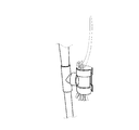
- FIG. 1 shows a mop dust suction tool 3 attached to a hose 2 of a vacuum cleaner body 1.
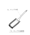
- FIG. 2 is a diagram of a mop.
- FIG. 3 shows the mop inserted into the dust suction tool 3 of the mop.
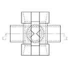
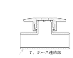
- FIG. 4 is a top view of the mop dust suction tool 3.
- the cylindrical cleaning part 6 and the hose connection part 7 are in parallel.
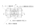
- FIG. 5 is a top view of the mop dust suction tool 3.
- the cylindrical cleaning part 6 is rotated by 90 ° with respect to the hose connecting part 7.
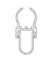
- 6 is a cross-sectional view taken along the line AA in FIG.
- FIG. 1 shows a mop dust suction tool 3 attached to a hose 2 of a vacuum cleaner body 1.
- FIG. 2 is a diagram of a mop.
- FIG. 3 shows the
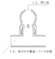
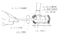
- FIG. 10 shows that the mop handle 4 is inserted into the cylindrical cleaning portion 6 from the opening 13 in the dust suction tool 3 of the mop, and the cylindrical cleaning portion 6 is rotated by 90 ° with respect to the hose connecting portion 7.
- FIG. 1 is an embodiment of the present invention, in which a mop dust suction tool 3 is attached to a hose 2 of a vacuum cleaner 1. *
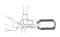
- FIG. 3 is an implementation example of the present invention, and by inserting a mop into the cylindrical cleaning part 6 of the mop dust suction tool 3 attached to the vacuum cleaner main body 1 in the suction operation state, You can carry a mop while cleaning the floor surface with an electric vacuum cleaner, and hold the mop at any time to clean the uneven surfaces such as the desk top surface, furniture, furniture, decorations, leaves of houseplants, etc. I was able to do it.
- FIG. 4 is a top view of the mop dust suction tool 3.
- the angle between the suction port 8 of the cylindrical cleaning part and the suction port 9 of the hose connecting part Is in a state where it cannot be sucked because it is 90 ° apart.
- FIG. 5 is a top view of the mop dust suction tool 3.
- the suction port 8 of the cylindrical cleaning part and the suction port of the hose connection part 9 is in a state where it can communicate with the vacuum cleaner main body 1 because it is in a state where it communicates.
- the suction port 8 of the cylindrical cleaning unit and the suction port 9 of the hose connection unit are changed by changing the angle of the cylindrical cleaning unit 6 of the mop dust suction tool 3 with respect to the hose connection unit 7 from 0 ° to 90 °.
- the amount of overlap can be changed, and the suction force can be adjusted.
- FIG. 9 shows that a portion having a complicated uneven surface is cleaned, and a dust or a mop handle to which dust is attached is inserted into the opening 13 provided in the dust suction tool 3 of the mop. It is the figure which rotated 90 degrees with respect to the hose connection part 7.
- FIG. 9 shows that a portion having a complicated uneven surface is cleaned, and a dust or a mop handle to which dust is attached is inserted into the opening 13 provided in the dust suction tool 3 of the mop. It is the figure which rotated 90 degrees with respect to the hose connection part 7.
- FIG. 10 is a plan view of a cylindrical cleaning unit in which a portion having a complicated uneven surface is cleaned, and a mop handle 4 to which dust or dust adheres is inserted into an opening 13 provided in a mop dust suction tool 3.
- 6 is rotated by 90 ° with respect to the hose connecting part 7, the suction port 8 of the cylindrical cleaning part and the suction port 9 of the hose connecting part are communicated, and the mop cleaning part 5 is connected to the cylindrical cleaning part 6
- the present invention enables not only cleaning in the home but also more reliable dust removal in a clean room of a precision product manufacturing factory. Further, by providing a slow power function to the suction port of the cylindrical cleaning unit and temporarily removing static electricity, dust attached to the mop cleaning unit can be removed more quickly. Further, by providing a groove on the inner side of the cylindrical cleaning unit 3 toward the suction port 8 of the cylindrical cleaning unit, the suction port becomes wider and the time for removing dust adhering to the mop cleaning unit is increased. Can be shortened, and static electricity is generated by friction with the fibers of the cleaning part of the mop.
Landscapes
- Engineering & Computer Science (AREA)
- Mechanical Engineering (AREA)
- Nozzles For Electric Vacuum Cleaners (AREA)
- Cleaning Implements For Floors, Carpets, Furniture, Walls, And The Like (AREA)
- Electric Vacuum Cleaner (AREA)
Abstract
Description
V ボード・T V 等広範囲の掃除が同時に可能となる。また、清掃部材を掃除機本体に収納した状態では、電動送風機の吸引力で清掃部材に付着した塵埃を集塵袋内に集塵するため、常に清掃部材をクリーニングすることができ、清潔な状態を保つことができる。 As a method of sucking mop dust, the cleaning part of the mop can be stored in the main body of the vacuum cleaner, and in the stored state, the dust attached to the cleaning part is collected in the dust bag by the suction force of the vacuum cleaner. A vacuum cleaner has been devised that can also clean the floor. This vacuum cleaner can be used for normal floor cleaning, non-floor tables, shelves, A
A wide range of cleaning such as V board and TV can be performed simultaneously. In the state where the cleaning member is housed in the cleaner body, the dust attached to the cleaning member is collected in the dust bag by the suction force of the electric blower, so the cleaning member can always be cleaned and is in a clean state. Can keep.
特開2000-312661
特開2003-153830
JP2006-340826 JP-A-9-173264
JP 2000-312661 A
JP 2003-153830 A
JP2006-340826
電気掃除機本体
2、
ホース
3、
モップの埃の吸引具
4、
モップの柄
5、
モップの清掃部
6、
筒状の清掃部
7、
ホース連結部
8、
筒状の清掃部の吸引口
9、
ホース連結部の吸引口
10、
吸引口が連通している状態
11、
矢印A
12、
矢印B
13、
開口部 1,
Vacuum cleaner body 2,
Hose 3,
Mop dust suction tool 4,
Mop handle 5,
Mop cleaning part 6,
Cylindrical cleaning section 7,
The suction port 9 of the cylindrical cleaning section,
Suction port 10 of the hose connection part,
State 11 where suction port is communicating,
Arrow A
12,
Arrow B
13,
Aperture
Claims (3)
- 本発明は、電気掃除機の本体に接続され床掃除の吸引部を先端に装着されたホースの途中に容易に取り付けることができる連結部を有し、モップの埃、塵の清掃のための吸気口を有することを特徴とするモップの埃の吸引具。 The present invention has a connecting part that is connected to the main body of a vacuum cleaner and can be easily attached in the middle of a hose attached to the end of a suction part for floor cleaning. A mop dust suction tool characterized by having a mouth.
- 本発明は、モップの清掃部を挿入し、モップ清掃部を挿入方向に往復移動可能な筒状のモップ清掃部を有することを特徴とする請求項1記載のモップの埃の吸引具。 2. The mop dust suction device according to claim 1, further comprising a cylindrical mop cleaning portion that is capable of inserting a mop cleaning portion and reciprocatingly moving the mop cleaning portion in the insertion direction.
- 本発明は、モップの埃の吸引具が有する筒状の清掃部の側面に、モップの柄を挿入するための開口部を有することを特徴とする請求項1記載のモップの埃の吸引具。 2. The mop dust suction tool according to claim 1, wherein the mop dust suction tool has an opening for inserting a mop handle on a side surface of a cylindrical cleaning portion of the mop dust suction tool.
Priority Applications (3)
| Application Number | Priority Date | Filing Date | Title |
|---|---|---|---|
| KR1020127030904A KR20130121681A (en) | 2010-04-26 | 2011-04-20 | Mop dust absorption tool |
| US13/643,520 US8689392B2 (en) | 2010-04-26 | 2011-04-20 | Mop dust suction device |
| CN201180031761.8A CN102970912B (en) | 2010-04-26 | 2011-04-20 | The attraction utensil of the dust of rag and electric dust collector |
Applications Claiming Priority (2)
| Application Number | Priority Date | Filing Date | Title |
|---|---|---|---|
| JP2010101551A JP5025031B2 (en) | 2010-04-26 | 2010-04-26 | Mop dust suction tool |
| JP2010-101551 | 2010-04-26 |
Publications (1)
| Publication Number | Publication Date |
|---|---|
| WO2011136112A1 true WO2011136112A1 (en) | 2011-11-03 |
Family
ID=44861418
Family Applications (1)
| Application Number | Title | Priority Date | Filing Date |
|---|---|---|---|
| PCT/JP2011/059766 WO2011136112A1 (en) | 2010-04-26 | 2011-04-20 | Mop dust absorption tool |
Country Status (5)
| Country | Link |
|---|---|
| US (1) | US8689392B2 (en) |
| JP (1) | JP5025031B2 (en) |
| KR (1) | KR20130121681A (en) |
| CN (1) | CN102970912B (en) |
| WO (1) | WO2011136112A1 (en) |
Cited By (1)
| Publication number | Priority date | Publication date | Assignee | Title |
|---|---|---|---|---|
| JP2020028811A (en) * | 2017-07-31 | 2020-02-27 | アイリスオーヤマ株式会社 | Cleaner support device and vacuum cleaner unit |
Families Citing this family (4)
| Publication number | Priority date | Publication date | Assignee | Title |
|---|---|---|---|---|
| US9863545B2 (en) | 2012-07-11 | 2018-01-09 | Keiichi Kawamura | Hose coupling device, mop suction device, electric vacuum cleaner, and ball valve |
| JP5616544B1 (en) * | 2013-09-18 | 2014-10-29 | 優子 青木 | Dust dust suction tool |
| BR112017013735A2 (en) | 2014-12-23 | 2018-03-13 | 3M Innovative Properties Co | convective system hose connection |
| IT201700048386A1 (en) * | 2017-05-04 | 2018-11-04 | Sauro Mandrioli | DEVICE FOR DUST REMOVAL |
Citations (3)
| Publication number | Priority date | Publication date | Assignee | Title |
|---|---|---|---|---|
| JP2003515373A (en) * | 1999-12-03 | 2003-05-07 | アクティエボラゲット エレクトロラックス | Equipment for vacuum cleaners |
| JP2004242731A (en) * | 2003-02-12 | 2004-09-02 | Tadashi Hirakata | Dedusting aid for vacuum cleaner |
| WO2009038291A1 (en) * | 2007-09-19 | 2009-03-26 | Suk-Dong Jung | Device for removing dust by vacuum cleaner |
Family Cites Families (10)
| Publication number | Priority date | Publication date | Assignee | Title |
|---|---|---|---|---|
| CN2050116U (en) * | 1989-03-20 | 1989-12-27 | 张纪民 | Gas-flow rotary regulator |
| JPH09173264A (en) | 1995-12-22 | 1997-07-08 | Takeshi Hoshino | Dust remover for mop |
| JP2000312661A (en) | 1999-04-30 | 2000-11-14 | First Kogyo Kk | Vacuum cleaner |
| US7024723B2 (en) * | 2001-06-15 | 2006-04-11 | Headwaters R&D, Inc. | Duster cleaning member for a vacuum cleaner |
| JP2003153830A (en) | 2001-11-20 | 2003-05-27 | Duskin Co Ltd | Stationary dust collector for floor |
| CN2629300Y (en) * | 2003-04-09 | 2004-07-28 | 优比(中国)有限公司 | Negative and positive integrated connection box |
| US20060096055A1 (en) * | 2004-11-09 | 2006-05-11 | Electrolux Home Care Products, Ltd. | Dusting device for a central vacuum system |
| JP2006340826A (en) | 2005-06-08 | 2006-12-21 | Matsushita Electric Ind Co Ltd | Vacuum cleaner |
| JP4305445B2 (en) * | 2005-12-05 | 2009-07-29 | トヨタ自動車株式会社 | Internal combustion engine |
| CN100420860C (en) * | 2006-08-15 | 2008-09-24 | 陈建忠 | Progressive regulating expansion block self locking expansion pipe |
-
2010
- 2010-04-26 JP JP2010101551A patent/JP5025031B2/en not_active Expired - Fee Related
-
2011
- 2011-04-20 WO PCT/JP2011/059766 patent/WO2011136112A1/en active Application Filing
- 2011-04-20 KR KR1020127030904A patent/KR20130121681A/en not_active Application Discontinuation
- 2011-04-20 US US13/643,520 patent/US8689392B2/en not_active Expired - Fee Related
- 2011-04-20 CN CN201180031761.8A patent/CN102970912B/en not_active Expired - Fee Related
Patent Citations (3)
| Publication number | Priority date | Publication date | Assignee | Title |
|---|---|---|---|---|
| JP2003515373A (en) * | 1999-12-03 | 2003-05-07 | アクティエボラゲット エレクトロラックス | Equipment for vacuum cleaners |
| JP2004242731A (en) * | 2003-02-12 | 2004-09-02 | Tadashi Hirakata | Dedusting aid for vacuum cleaner |
| WO2009038291A1 (en) * | 2007-09-19 | 2009-03-26 | Suk-Dong Jung | Device for removing dust by vacuum cleaner |
Cited By (1)
| Publication number | Priority date | Publication date | Assignee | Title |
|---|---|---|---|---|
| JP2020028811A (en) * | 2017-07-31 | 2020-02-27 | アイリスオーヤマ株式会社 | Cleaner support device and vacuum cleaner unit |
Also Published As
| Publication number | Publication date |
|---|---|
| KR20130121681A (en) | 2013-11-06 |
| JP5025031B2 (en) | 2012-09-12 |
| CN102970912B (en) | 2016-08-03 |
| CN102970912A (en) | 2013-03-13 |
| US8689392B2 (en) | 2014-04-08 |
| JP2011229629A (en) | 2011-11-17 |
| US20130036572A1 (en) | 2013-02-14 |
Similar Documents
| Publication | Publication Date | Title |
|---|---|---|
| US8918947B2 (en) | Crevice tool for vacuum cleaners | |
| WO2011136112A1 (en) | Mop dust absorption tool | |
| EP1949840A3 (en) | Double sided suction nozzle for use in vacuum cleaner | |
| US11445876B2 (en) | Cleaner | |
| US11937762B2 (en) | Vacuum tools | |
| JP2010213886A (en) | Vacuum cleaner | |
| US11759074B2 (en) | Suction accessory device for vacuuming and cleaning hard-to-reach and/or delicate places and objects | |
| WO2007084543A3 (en) | Stair cleaning vacuum cleaner | |
| KR200485335Y1 (en) | Electrical vacuum cleaner with damp cloth | |
| JP3202109U (en) | Inlet head and auxiliary tool for screen door cleaning | |
| US11266282B2 (en) | Suction tool and electric vacuum cleaner | |
| US20130306107A1 (en) | Vacuum Attachment System | |
| KR20200119400A (en) | Robot cleaner with detachable suction | |
| US10238257B2 (en) | Vacuum attachment including a pressurized air source | |
| KR200436848Y1 (en) | a cleaning-unit for vacuum cleaner | |
| TWM429453U (en) | Suction cleaner structure with replaceable suction installation | |
| RU2328205C1 (en) | Nozzle to vacuum cleaner | |
| CN104259116A (en) | Sweeping tool with dust collecting component | |
| JP2011224076A (en) | Flexibly applicable suction tool for vacuum cleaner | |
| US20120023697A1 (en) | Vacuum attachment assembly | |
| JP2013094211A (en) | Suction implement for vacuum cleaner and the vacuum cleaner using the same | |
| RU61107U1 (en) | Vacuum cleaner nozzle | |
| KR101254851B1 (en) | Adapter for connecting cleaner body and suction head | |
| KR200475908Y1 (en) | Suction device of vacuum cleaner | |
| JP2013034817A (en) | Duster cleaning device |
Legal Events
| Date | Code | Title | Description |
|---|---|---|---|
| WWE | Wipo information: entry into national phase |
Ref document number: 201180031761.8 Country of ref document: CN |
|
| 121 | Ep: the epo has been informed by wipo that ep was designated in this application |
Ref document number: 11774895 Country of ref document: EP Kind code of ref document: A1 |
|
| WWE | Wipo information: entry into national phase |
Ref document number: 13643520 Country of ref document: US |
|
| NENP | Non-entry into the national phase |
Ref country code: DE |
|
| ENP | Entry into the national phase |
Ref document number: 20127030904 Country of ref document: KR Kind code of ref document: A |
|
| 122 | Ep: pct application non-entry in european phase |
Ref document number: 11774895 Country of ref document: EP Kind code of ref document: A1 |