WO2011132313A1 - 映像処理装置、映像処理方法及び映像処理プログラム - Google Patents
映像処理装置、映像処理方法及び映像処理プログラム Download PDFInfo
- Publication number
- WO2011132313A1 WO2011132313A1 PCT/JP2010/057259 JP2010057259W WO2011132313A1 WO 2011132313 A1 WO2011132313 A1 WO 2011132313A1 JP 2010057259 W JP2010057259 W JP 2010057259W WO 2011132313 A1 WO2011132313 A1 WO 2011132313A1
- Authority
- WO
- WIPO (PCT)
- Prior art keywords
- line
- sight
- video
- image
- mirror
- Prior art date
- Legal status (The legal status is an assumption and is not a legal conclusion. Google has not performed a legal analysis and makes no representation as to the accuracy of the status listed.)
- Ceased
Links
Images



















Classifications
-
- B—PERFORMING OPERATIONS; TRANSPORTING
- B60—VEHICLES IN GENERAL
- B60R—VEHICLES, VEHICLE FITTINGS, OR VEHICLE PARTS, NOT OTHERWISE PROVIDED FOR
- B60R11/00—Arrangements for holding or mounting articles, not otherwise provided for
- B60R11/04—Mounting of cameras operative during drive; Arrangement of controls thereof relative to the vehicle
-
- G—PHYSICS
- G06—COMPUTING OR CALCULATING; COUNTING
- G06T—IMAGE DATA PROCESSING OR GENERATION, IN GENERAL
- G06T19/00—Manipulating three-dimensional [3D] models or images for computer graphics
- G06T19/006—Mixed reality
Definitions
- the present invention relates to a video processing apparatus, a video processing method, and a video processing program for generating a video for educating a vehicle driver.
- an accident video is acquired by a drive recorder mounted on a vehicle, and the accident video is reproduced to be used for traffic safety education.
- the drive recorder detects an impact in a collision accident or dangerous driving such as sudden braking and sudden steering operation, the drive recorder records a front image of the host vehicle and a traveling state of the host vehicle.
- the driver can confirm only the front video of the vehicle regarding the situation where dangerous driving occurs.
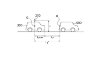
- FIG. 43 is an example of the driving situation
- FIG. 44 is an image of the driving of FIG. 43 acquired by the drive recorder.
- the host vehicle 300 is traveling on the lane 600.
- the other vehicle 500 travels on a lane 601 adjacent to the lane 600 and is located at an obliquely right rear side of the host vehicle 300.
- the own vehicle 300 and the other vehicle 500 may collide.
- an image recorded by the drive recorder of the host vehicle 300 is shown in FIG. 44, and a front image of the host vehicle 300 is displayed in FIG.
- the front video in FIG. 44 is presented to the viewer in the traffic safety education, the viewer cannot learn that dangerous driving has occurred in the situation as shown in FIG. This is because dangerous driving occurs at the right rear of the host vehicle 300 and is not recorded in the drive recorder.
- an object is to provide a video processing device, a video processing method, and a video processing program for generating a video for educating a vehicle driver.
- An observation image generation means for generating an observation image on the front side and the right side and / or the left side of the host vehicle, which is observable by a driver of the host vehicle, based on a peripheral image of the host vehicle;
- a line-of-sight locus generating means for generating a line-of-sight locus of the driver for the observation image;
- Display video generation means for generating a display video by superimposing the line-of-sight locus on the observation video;
- a video processing apparatus is provided.
- (A) is explanatory drawing (1) which shows an example of the calculation method of the gaze origin P and a gaze vector
- (b) is explanatory drawing which shows pitch angle (theta) (beta)
- (c) is explanatory drawing which shows position angle (theta) (alpha).
- Explanatory drawing which shows the relationship between the three-dimensional projection surface on which a periphery image
- Explanatory drawing which shows the relationship between the vehicle window image
- the flowchart which shows an example of the flow of the process which the driving
- the schematic diagram which shows a mode that a driver
- Explanatory drawing which shows the relationship between the vehicle window image
- the perspective view which shows the relationship between the own vehicle and another vehicle.
- An example of the block diagram which shows the function structure of each apparatus concerning 2nd Embodiment.
- the schematic diagram which shows the three-dimensional projection surface on which a periphery image
- Explanatory drawing which shows an example of the extraction method of a target object.
- (A) is explanatory drawing (1) which shows an example of the calculation method of angle (DELTA) (theta) which a sight line vector and an object vector form
- (b) is an example of the calculation method of angle (DELTA) (theta) which an sight line vector and an object vector form. It is explanatory drawing (2) which shows this.
- (A) is explanatory drawing (1) which shows an example of the calculation method of angle (DELTA) (theta) which a mirror gaze vector and an object vector form
- (b) is a calculation method of angle (DELTA) (theta) which a mirror gaze vector and an object vector form.
- the flowchart which shows an example of the flow of the whole process which the driving
- the flowchart which shows an example of the flow of the recognition determination process concerning 2nd Embodiment.
- FIG. 10 is a flowchart showing an example of a flow of mirror processing of line-of-sight data according to the second embodiment.
- the flowchart which shows an example of the flow of the target object extraction process concerning 2nd Embodiment.
- the flowchart which shows an example of the flow of the recognition presence determination process concerning 2nd Embodiment.
- An example of relative information DB Explanatory drawing which shows an example of the calculation method of the relative distance L.
- FIG. An example of a recognition result DB.
- surface which shows the relationship between TTC and risk.
- An example of driving. 43 is an operation image acquired by the drive recorder.
- the driving image processing apparatus 100 generates an observation image that is estimated to be observed by the driver of the host vehicle 300 based on the surrounding information of the host vehicle 300.
- the surrounding information of the own vehicle 300 includes at least an image around the own vehicle, for example, an image of an object such as another vehicle around the own vehicle 300 and a road.
- the observation image is an image that can be observed by the driver in front, right side, and / or left side of the host vehicle 300, and is viewed through a vehicle window image and / or a mirror that the driver observes through the window of the host vehicle 300.
- the observation video may include a video that the driver can observe behind the host vehicle 300.
- the driving image processing apparatus 100 generates a display image by further superimposing the driver's line-of-sight locus on the observation image.
- the line-of-sight locus is a locus of a point of interest that is presumed that the driver is most focused on the observation video.
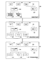
- FIG. 1 is an example of a connection relationship among a driving image processing device, an information acquisition device, and a driving education terminal according to the first embodiment.
- FIG. 2 is an example of a block diagram illustrating a hardware configuration of the driving video processing device, the information acquisition device, and the driving education terminal.
- the driving image processing apparatus 100 generates an observation image of the driver of the host vehicle 300 based on the peripheral information, and generates a display image by superimposing the observation image and the driver's line-of-sight locus.
- the information acquisition device 200 acquires various information such as the surrounding information of the host vehicle 300 and the line-of-sight data of the driver of the host vehicle 300.
- the driving education terminal 250 is a terminal for a viewer such as a driver who is a subject of safe driving education to view a display image generated by the driving image processing apparatus 100.
- the driving image processing device 100, the information acquisition device 200, and the driving education terminal 250 are connected so that various types of information can be transmitted and received.
- Examples of connection methods include interfaces such as SCSI (Small Computer System Interface) and USB (Universal Serial Bus), and networks such as the Internet.
- the driving image processing device 100 includes, for example, a CPU (Central Processing Unit) 101, a ROM (Read Only Memory) 102, a RAM (Random Access Memory) 103, and an input / output A device I / F 104 and a communication I / F (InterFace) 108 are included. These are connected to each other via a bus 109.
- a CPU Central Processing Unit
- ROM Read Only Memory
- RAM Random Access Memory
- I / F 104 and a communication I / F (InterFace) 108 are included. These are connected to each other via a bus 109.
- the input / output device I / F 104 is connected to input / output devices such as the display 105, the mouse 106, and the keyboard 107.
- the ROM 102 stores various control programs related to various controls described later performed by the driving image processing apparatus 100.
- the RAM 103 temporarily stores various information such as various control programs in the ROM 102, peripheral information acquired from the information acquisition device 200, and line-of-sight data.
- the RAM 103 temporarily stores information such as various flags in accordance with the execution of various control programs.
- the CPU 101 develops various control programs stored in the ROM 102 in the RAM 103 and performs various controls described later.
- the communication I / F 108 performs communication such as transmission / reception of commands or data between the information acquisition device 200 and the driving education terminal 250 based on the control of the CPU 101.
- the bus 109 includes, for example, a PCI (Peripheral Component Interconnect) bus, an ISA (Industrial Standard Architecture) bus, and the like, and connects the above components to each other.
- PCI Peripheral Component Interconnect
- ISA Industry Standard Architecture
- the information acquisition device 200 includes, for example, a CPU 201, a ROM 202, a RAM 203, an input / output device I / F 204, and a communication I / F 207. These are connected to each other via a bus 208.
- (A) Input / output device I / F The input / output device I / F 204 is connected to the peripheral information acquisition device 205, the line-of-sight detection device 206, and the like. Information detected by the peripheral information acquisition device 205 and the line-of-sight detection device 206 is output to the RAM 203, the CPU 201, the communication I / F 207, and the like via the input / output device I / F 204.
- the peripheral information acquisition device 205 acquires peripheral information around the host vehicle 300.
- the surrounding information may include one or a plurality of objects existing around the host vehicle 300.
- the object is an obstacle existing around the host vehicle 300, and specifically, is an obstacle that the driver should recognize when driving the host vehicle 300.
- the objects include vehicles such as cars, bicycles, and motorcycles, people, animals, and other objects that can interfere with traveling.
- the peripheral information acquisition device 205 acquires a peripheral video as peripheral information.
- the peripheral information acquisition device 205 includes an imaging device such as a CCD (Charge-Coupled Device) camera or a CMOS (Complementary Metal-Oxide Semiconductor) camera, and acquires peripheral video around the host vehicle 300.
- CCD Charge-Coupled Device
- CMOS Complementary Metal-Oxide Semiconductor
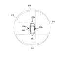
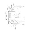
- FIG. 3 is an explanatory diagram showing the mounting position and photographing range of the peripheral information acquisition device.
- the peripheral information acquisition device 205 includes four cameras, for example, a front camera 205a, a right camera 205b, a left camera 205c, and a rear camera 205d.
- the front camera 205 a is attached to the center of the front bumper of the vehicle 300 and photographs the front of the vehicle 300.
- the rear camera 205d is attached to the center of the rear bumper of the vehicle 300 and photographs the rear of the vehicle 300.
- the right camera 205 b is attached to the center of the right side surface of the vehicle 300 and photographs the right side of the vehicle 300.
- the left camera 205 c is attached to the center of the left side surface of the vehicle 300 and photographs the left side of the vehicle 300.
- Each of the cameras 205a to 205d is, for example, a camera using an ultra-wide angle lens having a field angle of 180 degrees. Therefore, as shown in FIG. 3, the front camera 205 a captures the front area 210 of the vehicle 300, the right camera 205 b captures the right area 211 of the vehicle 300, and the left camera 205 c captures the left area of the vehicle 300.
- the rear camera 205 d captures the rear region 213 of the vehicle 300.
- the shooting areas of the respective cameras 205a to 205d are configured to overlap with areas shot by adjacent cameras.
- the camera characteristics such as the mounting position and mounting angle of each camera 205a to 205d, and other camera lens distortion correction values and focal length can be adapted to a spatial coordinate system with the center point O of the vehicle 300 as the origin. Correction, so-called calibration is performed. By executing this calibration, the images captured by the cameras 205a to 205d can be incorporated into a spatial coordinate system having the center point O of the vehicle 300 as the origin.
- the spatial coordinate system is represented by X, Y, and Z coordinates.
- Y is the forward direction of the vehicle
- X is the direction crossing the forward direction
- Z is the height direction.
- Each camera 205a to 205d is preferably attached to the center of the front, right side, left side, and rear side of the vehicle 300, as shown. However, it suffices if the shooting area of each camera 205a to 205d partially overlaps the shooting area of the adjacent camera, and the mounting position of each camera 205a to 205d is not particularly limited.
- the right camera 205 b and the left camera 205 c can be attached to the left and right door mirrors of the vehicle 300.
- the number of cameras is not limited to four as long as the shooting areas of each camera partially overlap and it is possible to capture a 360 ° range around the vehicle 300.
- each of the cameras 205a to 205d shoots 30 frames per second, for example.
- Video data captured by the peripheral information acquisition device 205 including the cameras 205a to 205d is stored in the RAM 203 via the input / output device I / F 204.
- the driving image processing apparatus 100 can generate the observation image based on the surrounding image of the entire periphery of the vehicle 300 by shooting the images with the cameras 205a to 205d.
- the peripheral information acquisition device 205 does not always acquire the peripheral information while driving, but records the peripheral information only when a dangerous driving is detected, for example, when a follow-up driving to the preceding vehicle is detected. You may make it do.
- the line-of-sight detection device 206 detects line-of-sight information such as the driver's face, eyeball, and iris.
- the line-of-sight detection device 206 includes an imaging device such as a CCD camera, a CMOS camera, or an infrared camera that can acquire driver's line-of-sight information.
- an imaging device such as a CCD camera, a CMOS camera, or an infrared camera that can acquire driver's line-of-sight information.
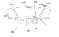
- the line-of-sight detection device 206 is provided, for example, on the dashboard 301 of the vehicle 300 as shown in FIGS. At this time, the line-of-sight detection device 206 can detect, for example, the driver's face and eyes from the front and can capture the face and eyes without being blocked by the handle 302. It is mounted on the board 301 at a predetermined angle. However, as long as the driver's face and eyes can be detected, the attachment position and the attachment angle are not limited.
- the characteristics of the line-of-sight detection device such as the mounting position and the mounting angle of the line-of-sight detection device 206 are corrected, so-called calibration, so as to be compatible with the spatial coordinate system with the center point O of the vehicle 300 as the origin.
- the line-of-sight detection device 206 captures, for example, 30 video frames per second, and the captured video data is stored in the RAM 203 via the input / output device I / F 204.
- the line of sight 150 It is possible to detect the line of sight 150 based on images of the driver's face, eyeball, iris, etc. detected by the line-of-sight detection device 206. When the driver's line of sight 150 is detected, the direction of the line of sight 150 indicates which direction the driver is viewing.
- the vehicle has windows such as a front window 306F, a right window 306R, a left window 306L, and a rear window (not shown), and each window is supported by a pillar.
- the pillar includes a front pillar 307F positioned above the front window 306F, a right pillar 307R and a left pillar 307L positioned on the right and left sides of the front window 306F, and a rear pillar 307B (not shown) on the rear side of the vehicle body. ) Etc. are included.
- the direction of the detected line of sight 150 is forward, it can be assumed that the driver has visually recognized the periphery of the host vehicle 300 through the front window 306F, for example. Further, if the direction of the line of sight 150 is toward the mirror 303, it can be assumed that the rear side and the rear side of the vehicle 300 are visually recognized via the mirror 303.
- the mirror 303 provided in the vehicle 300 includes door mirrors 303 ⁇ / b> L and 303 ⁇ / b> R provided near the left and right doors of the vehicle 300, a rearview mirror 303 ⁇ / b> B provided inside the vehicle 300, and a hood of the vehicle 300. And a fender mirror.
- FIG. 6 is an explanatory diagram illustrating an example of a region that can be confirmed by a mirror.
- the driver of the vehicle 300 can visually recognize the left mirror region 304L through the left door mirror 303L. Further, the driver can visually recognize the right mirror region 304R through the right door mirror 303R. Further, the driver can visually recognize the rearview mirror region 304B through the rearview mirror 303B.
- the ROM 202 stores various control programs executed by the information acquisition device 200.
- the RAM 203 temporarily stores various control programs, various flags, various information received from the peripheral information acquisition device 205 and the line-of-sight detection device 206 in the ROM 202.
- the communication I / F 207 transmits / receives data such as peripheral information and various commands to / from the driving video processing apparatus 100 based on the control of the CPU 201.
- the CPU 201 develops various control programs stored in the ROM 202 in the RAM 203 and performs various controls. For example, the CPU 201 controls the peripheral information acquisition device 205 and the line-of-sight detection device 206 by executing various control programs, and starts acquisition of various information such as peripheral video.
- the driving education terminal 250 is a terminal used by a user who receives safe driving education.
- the terminal can view the display video generated by the driving video processing apparatus 100.
- the driving education terminal 250 includes, for example, a CPU 251, a ROM 252, a RAM 253, an input / output device I / F 254, and a communication I / F 258. These are connected to each other via a bus 259.
- (A) Input / output device I / F The input / output device I / F 254 is connected to input / output devices such as a display 255, a mouse 256, and a keyboard 257. Further, the input / output device I / F 254 receives an instruction to display the display video from the user via the mouse 256 and the keyboard 257. A speaker or the like for outputting sound may be connected to the input / output device I / F 254.
- FIG. 7 is an example of a display of a terminal for driving education.
- the display 255 includes a display device including a front display 255F, a right display 255R, and a left display 255L, for example.
- the front display 255F is disposed in front of the viewer so as to face the viewer as shown in FIG.
- the right display 255R and the left display 255L are arranged on the right and left sides of the front display 255F, respectively. Further, the right display 255R and the left display 255L are disposed so as to have a predetermined angle with respect to the front display 255F so as to surround the central viewer.
- the display 255 is not limited to the configuration of FIG. 7 and may include an additional right display 255R ′ and a left display 255L ′ so as to surround the viewer. Further, the display 255 may be configured by a combination of flat display devices as shown in FIG. 7, or may be formed so as to surround the viewer with one display device that can be bent or bent. Further, the display 255 is not necessarily formed so as to surround the viewer, and may be composed of one flat display device. However, the display 255 is configured to surround the viewer with a predetermined angle as shown in FIG. 7, so that the viewer can view the display video as if he / she is driving. it can.
- the screen display area of the front display 255F includes a front car window video area 261F and a rearview mirror video area 262B.
- the forward vehicle window image displayed in the forward vehicle window image area 261F includes a vehicle window image that the driver of the host vehicle 300 observes through the forward window 306F in FIG.
- the front vehicle window image may include vehicle body structures such as the front pillar 307F and the dashboard 301 of the host vehicle 300.
- the front car window image is mainly composed of the front car window image, but may include a part of the right car window image and the left car window image observed by the driver through the right window 306R and the left window 306L.
- the rearview mirror video area 262B includes a rearview video that the driver observes through the rearview mirror 303B of FIG.
- the rearview mirror video is a video corresponding to the rearview mirror area 304B of FIG.
- various correspondence table DB130 memorize
- the display area of the screen of the right display 255R includes a right vehicle window video area 261R and a right mirror video area 262R.
- the right vehicle window image displayed in the right vehicle window image region 261R includes a vehicle window image that the driver of the host vehicle 300 observes through the right window 306R in FIG.
- the right vehicle window image may include a vehicle body structure such as the right pillar 307R of the host vehicle 300.
- the right vehicle window image is mainly composed of the right vehicle window image, but a part of the front vehicle window image may be included.
- the right mirror image area 262R includes a right mirror image that the driver observes through the right door mirror 303R in FIG.
- the right mirror image is an image corresponding to the right mirror region 304R of FIG.
- various correspondence table DB130 has memorize
- the screen display area of the left display 255L includes a left car window video area 261L and a left mirror video area 262L.
- the left vehicle window image displayed in the left vehicle window image area 261L includes a vehicle window image that the driver of the host vehicle 300 observes through the left window 306L in FIG.
- the left vehicle window image may include a vehicle body structure such as the left pillar 307L of the host vehicle 300.
- the left side window image is mainly composed of the left side window image, but a part of the front window image may be included.
- the left-side mirror image area 262L includes a left-side mirror image that the driver observes through the left-side door mirror 303L in FIG.
- the left mirror image is an image corresponding to the left mirror region 304L of FIG.
- various correspondence table DB130 has memorize
- the CPU 251 develops various control programs stored in the ROM 252 in the RAM 253, acquires display image data from the driving image processing apparatus 100, and outputs the display image data to the display 255 or the like.
- the other configuration is substantially the same as that of the driving image processing apparatus 100, and thus the description thereof is omitted.
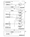
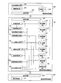
- FIG. 8 is an example of a block diagram showing a functional configuration of each device according to the first embodiment.
- the connection lines of the functional units shown in FIG. 8 show an example of the data flow, and do not describe all the data flows.
- (3-1) Information Acquisition Device When the hardware configurations of the information acquisition device 200 cooperate with each other to execute a program, the information acquisition device 200 functions as each functional unit described later.
- the functional units of the information acquisition apparatus 200 include, for example, a peripheral information acquisition unit 220, a line-of-sight detection unit 221, a transmission / reception unit 222, an acquisition data DB 223, and the like.
- the peripheral information acquisition unit 220 is a peripheral image captured by the peripheral information acquisition device 205 including the front camera 205a, the right camera 205b, the left camera 205c, and the rear camera 205d shown in FIG. A video is acquired and stored in the acquisition data DB 223.
- the line-of-sight detection unit 221 is a line-of-sight vector indicating the direction of the line-of-sight origin P and the direction of the line of sight 150 based on the driver's face, eyeball, iris, and other images detected by the line-of-sight detection device 206. 150a is calculated.
- FIG. 9 is an explanatory diagram showing an example of a method for calculating the line-of-sight origin P and the line-of-sight vector.
- the line-of-sight detection unit 221 calculates facial feature points based on images such as a face, eyeballs, and irises, and compares the feature points with driver feature values stored in advance.
- the line-of-sight detection unit 221 extracts the orientation of the face based on the comparison result and the image of the face, eyeball, iris, etc., and the center between the left eyeball 152L and the right eyeball 152R shown in FIG. The position is detected as the line-of-sight origin P.
- the line-of-sight detection unit 221 calculates the center position of the iris 153a, that is, the center position of the pupil 153b. Furthermore, the line-of-sight detection unit 221 calculates the line-of-sight vector 150a based on the line-of-sight origin P and the center position of the pupil 153b. Since the driver can change the head forward / backward / left / right and up / down, the position of the line-of-sight origin P with respect to the center point O of the spatial coordinate system is changed according to the position and orientation of the head.
- the line-of-sight vector 150a includes a pitch angle ⁇ that is an angle between the line-of-sight vector 150a and the XY plane, and an azimuth angle that is an angle between the line-of-sight vector 150a and the YZ plane. ⁇ .
- the line-of-sight vector 150 a can be defined by coordinates in a spatial coordinate system with an arbitrary center point O of the vehicle 300 as the origin.
- the line-of-sight detection unit 221 stores the line-of-sight origin P and the line-of-sight vector 150a in the acquisition data DB 223.
- the transmission / reception unit 224 of the information acquisition device 200 transmits / receives various commands and various data in the acquisition data DB 225 to / from the transmission / reception unit 120 of the driving video processing device 100.
- the acquisition data DB 223 stores peripheral information, line-of-sight data detected by the line-of-sight detection unit 226, and the like.
- the functional units of the driving video processing device 100 include, for example, a transmission / reception unit 120, a car window video generation unit 121, a mirror video generation unit 122, a line-of-sight locus generation unit 123, a display video generation unit 124, and the like. Further, the driving image processing apparatus 100 includes a peripheral information DB 125, a vehicle window image DB 126, a mirror image DB 127, a vehicle body structure DB 128, a line-of-sight data DB 129, various correspondence tables DB 130, and the like for storing various information.
- the transmission / reception unit 120 of the driving video processing device 100 transmits / receives various data, various commands, and the like to / from the transmission / reception unit 222 of the information acquisition device 200.
- the peripheral information DB 125 acquires and stores a peripheral video around the host vehicle from the information acquisition device 200 as peripheral information around the host vehicle.
- the peripheral video includes video captured by the peripheral information acquisition device 205 including the front camera 205a, the right camera 205b, the left camera 205c, and the rear camera 205d.
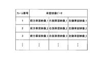
- FIG. 10 is an example of the peripheral information DB.
- the peripheral information DB 125 stores a frame number and video data of each camera 205 for each frame.
- the video data includes a front video shot by the front camera 205a, a right video shot by the right camera 205b, a left video shot by the left camera 205c, and a rear video shot by the rear camera 205d.
- the line-of-sight data DB 129 acquires the line-of-sight origin P and the line-of-sight vector 150a of the driver of the host vehicle from the information acquisition device 200 and stores them.
- FIG. 11 shows an example of the line-of-sight data DB.
- the line-of-sight data DB 129 acquires and stores the frame number, the line-of-sight origin P, and the line-of-sight vector 150a from the information acquisition apparatus 200 for each frame.
- the line-of-sight vector 150a is defined by the pitch angle ⁇ and the azimuth angle ⁇ .
- the line-of-sight origin P may be defined by coordinates in a spatial coordinate system with an arbitrary center point O of the vehicle 300 as the origin.
- the line-of-sight data DB 129 further stores the line-of-sight locus calculated by the line-of-sight locus generation unit 123 described later for each frame.
- the line-of-sight locus is a locus of a point of interest that is presumed that the driver is most focused on the observation video, and is defined by coordinates on the display area of the displays 255F, 255R, and 255L.
- the vehicle body structure DB 128 stores vehicle body structures such as the front pillar 307F, the dashboard 301, the right pillar 307R, and the left pillar 307L for each vehicle type.
- the vehicle body structure DB 128 stores, for example, video data of each pixel constituting the vehicle body structure in association with each coordinate of the display area of each display 255F, 255R, and 255L.
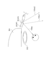
- FIG. 12 is an explanatory diagram showing the relationship between the three-dimensional projection surface onto which the peripheral image is projected, the car window image, and the mirror image.
- FIG. 13 is an explanatory diagram illustrating a relationship between a vehicle window image and a mirror image on a three-dimensional projection plane and a display area of each display.
- the peripheral image projected on the three-dimensional projection plane 400 as shown in FIG. 12 is generated by processing and synthesizing the video data captured by each camera 205.
- the three-dimensional projection plane 400 is assumed to be a bowl-shaped projection plane centered on the host vehicle 300. Note that the correspondence between the coordinates of the pixels of the cameras 205a to 205d and the coordinates of the three-dimensional projection plane 400 is defined in advance.
- the image data of each pixel of each of the cameras 205a to 205d is coordinate-converted to the 3D projection plane 400 based on the association, so that a peripheral image projected on the 3D projection plane 400 can be generated.
- the three-dimensional projection plane 400 includes a front vehicle window image 400F, a right vehicle window image 400R, and a left vehicle window image 400L on the front side of the host vehicle 300.
- the front window image 400F is a vehicle window image that the driver of the host vehicle 300 observes through the front window 306F in FIG.
- the right vehicle window image 400R and the left vehicle window image 400L are vehicle window images that the driver observes through the right window 306R and the left window 306L. It is assumed that which region on the three-dimensional projection plane 400 corresponds to the front vehicle window image 400F, the right vehicle window image 400R, and the left vehicle window image 400L is determined in advance.
- the three-dimensional projection plane 400 includes a right-side mirror image 400MR that the driver observes through the right-side door mirror 303R and a left-side mirror image 400ML that is observed through the left-side door mirror 303L on the diagonally rear side of the host vehicle 300. ,including.
- the three-dimensional projection plane 400 includes a rearview mirror image 400MB that the driver observes via the rearview mirror 303B on the rear side of the host vehicle 300. Similarly to the above, it is assumed that which region of the image on the three-dimensional projection plane 400 corresponds to the right mirror image 400MR, the left mirror image 400ML, and the rearview mirror image 400MB.
- the vehicle window images 400F, 400R, and 400L and the mirror images 400MB, 400MR, and 400ML are associated with the display areas of the respective displays 255F, 255R, and 255L.
- the front window image 400F is associated with the front window image area 261F.
- the coordinates of each pixel of the front car window image 400F on the three-dimensional projection plane 400 and the coordinates of the front car window image area 261F on the front display 255F are associated with each other. That is, as shown in FIG. 13, the coordinate Pa of the front window image 400F is associated with the coordinate Pa 'of the front window image area 261F.
- the coordinates of each pixel of the image and the coordinates of the front window image area 261F on the front display 255F are associated with each other. Yes.
- This association is defined in advance based on a predetermined viewpoint of the driver who is driving the vehicle. Therefore, it is possible to generate the video based on the viewpoint to the driver by generating the video by coordinate conversion based on the association.
- the video data acquired by each of the cameras 205a to 205d is composed of a plurality of pixels, and the plurality of pixels are configured as vehicle window images 400F, 400R, and 400L and mirror images 400MR, 400ML, and 400MB. Each pixel to be included is included.
- the various associations described above are stored in the various correspondence table DB 130.
- the right vehicle window image 400R is associated with the right vehicle window image region 261R
- the left vehicle window image 400L is associated with the left vehicle window image region 261L.
- the coordinate Pb of the left window image 400L is associated with the coordinate Pb 'of the left window image region 261L.
- the right mirror image 400MR is associated with the right mirror image region 262R
- the left mirror image 400ML is associated with the left mirror image region 262L.
- the coordinates Pe of the right mirror image 400MR are associated with the coordinates Pe ′ of the right mirror image area 262R
- the coordinate Pd of the left mirror image 400ML is associated with the coordinate Pd ′ of the left mirror image area 262L.
- the rearview mirror image 400MB is associated with the rearview mirror image area 262B.
- the coordinates Pc of the rearview video 400MB are associated with the coordinates Pc 'of the rearview video area 262B.
- the vehicle window image generation unit 121 includes vehicle window images 400F, 400R, and 400L shown in FIGS. 12 and 13 and vehicle window images on the display 255. Based on the association with the areas 261F, 261R, and 261L, the vehicle window images 400F, 400R, and 400L are generated. Further, the vehicle window image generation unit 121 refers to the vehicle body structure DB 128 and reads the vehicle body structure of the corresponding vehicle type. The vehicle window image generation unit 121 generates the vehicle window images 400F, 400R, and 400L by further incorporating the vehicle body structure.
- the car window video generation unit 121 reads out peripheral information including video data acquired by the cameras 205a to 205d from the peripheral information DB 125 of FIG.
- the vehicle window image generation unit 121 reads out the correspondence between the coordinates of each pixel constituting each vehicle window image and the coordinates of each vehicle window image area on the display 255 from the various correspondence table DB 130.
- the car window image generation unit 121 reads the association between the coordinates of each pixel of the front car window image 400F and the coordinates of the front car window image area 261F of the front display 255F from the various correspondence table DB 130.
- the vehicle window image generation unit 121 performs coordinate conversion of the image data of each pixel constituting each vehicle window image in the peripheral information onto each vehicle window image area on the display 255 based on the association. For example, the vehicle window image generation unit 121 performs coordinate conversion on the image data of each pixel of the front window image 400F on the front window image region 261F based on the association.
- the vehicle window image generation unit 121 refers to the vehicle body structure in the vehicle body structure DB 128 based on the vehicle type of the vehicle from which the peripheral information has been acquired. For example, the vehicle window image generation unit 121 reads the association between the image data of each pixel constituting the vehicle body structure and each coordinate on the display area of each display 255F, 255R, and 255L. Further, the vehicle window image generation unit 121 incorporates the image data of each pixel constituting the vehicle body structure into each coordinate of the display area of each display 255 based on the association, so that the front vehicle window image 400F and the right vehicle window image 400R. And the left vehicle window image 400L is generated. That is, vehicle window images 400F, 400R, and 400L in which the image observed through the window and the vehicle body structure are combined are generated.
- the mirror image generation unit 122 corresponds to each mirror image 400MR, 400ML, and 400MB shown in FIGS. 12 and 13 and each mirror image area 262R, 262L, and 262B on the display 255. A mirror image is generated based on the attachment. Furthermore, the mirror image generation unit 122 further generates the mirror images 400MB, 400MR, and 400MB by further incorporating the vehicle body structure read from the vehicle body structure DB 128.
- the mirror video generation unit 122 reads the peripheral information from the peripheral information DB 125. In addition, the mirror video generation unit 122 reads the correspondence between the coordinates of each pixel constituting each mirror video in the peripheral information and each coordinate of each mirror video area on the display 255 from the various correspondence table DB 130.
- the mirror image generation unit 122 performs coordinate conversion of the image data of each pixel constituting each mirror image in the peripheral information onto each mirror image amount area on the display 255 based on the association.
- the mirror image generation unit 122 generates a right mirror image 400MR, a left mirror image 400ML, and a rearview mirror image 400MB incorporating the vehicle body structure based on the vehicle body structure of the vehicle body structure DB 128. That is, mirror images 400MR, 400ML, and 400MB in which the image observed through the mirror 303 and the vehicle body structure are combined are generated.
- the process of incorporating the vehicle body structure into the car window image and mirror image is not necessarily required.
- the region where the driver's line of sight is shielded by a pillar or the like can be reproduced by incorporating the vehicle body structure into the vehicle window image and the mirror image. That is, it is possible to generate more accurately an image that is estimated to be actually viewed by the driver. Therefore, the viewer views the vehicle window image in which the vehicle body structure is incorporated with the driving education terminal 250, so that what area is dead by the vehicle body structure such as a pillar, It is possible to grasp whether or not dangerous driving has occurred. Thereby, safe driving education can be performed effectively.
- FIG. 14 is an example of a car window video DB.
- the vehicle window image DB 126 stores the vehicle window image generated by the vehicle window image generation unit 121.
- the vehicle window image DB 126 stores a frame number, a front vehicle window image 400F, a right vehicle window image 400R, and a left vehicle window image 400L for each frame.
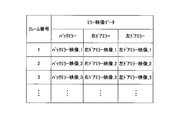
- FIG. 15 is an example of a mirror video DB.
- the mirror video DB 127 stores the mirror video generated by the mirror video generation unit 122.
- the mirror image DB 127 stores a frame number, a rearview mirror image 400MB, a right mirror image 400MR, and a left mirror image 400ML for each frame.
- Gaze Trajectory Generation Unit 123 displays the display areas of the front display 255F, the right display 255R, and the left display 255L based on the gaze origin P and the gaze vector 150a of the gaze data DB 129 in FIG. The driver's line-of-sight trajectory is calculated.
- the line-of-sight trajectory is derived as follows. As shown in FIG. 12, the line-of-sight vector 150a starting from the line-of-sight origin P intersects the three-dimensional projection plane 400 at a point VP. This point VP is converted into a line-of-sight locus which is a point on the display area of the display 255.
- the correspondence between the line-of-sight origin P and the line-of-sight vector and the line-of-sight locus that is the coordinates on the display area of the display 255 is stored in advance in the various correspondence table DB 130.
- the line-of-sight locus generation unit 123 reads the line-of-sight origin P and the line-of-sight vector 150a of the line-of-sight data DB 129, and calculates the line-of-sight locus based on the read line-of-sight origin P and line-of-sight vector 150a and the association.
- the line-of-sight locus generation unit 123 stores the calculated line-of-sight locus in the line-of-sight data DB 129 as shown in FIG.
- the display video generation unit 124 reads the vehicle window video of the vehicle window video DB 126 and the mirror video of the mirror video DB 127 for the frame for which the display video is to be generated. Further, the display video generation unit 124 reads the line-of-sight locus of the corresponding frame from the line-of-sight data DB 129. Further, the display video generation unit 124 reads out the positional relationship between each vehicle window video area and each mirror video area from the various correspondence table DB 130. For example, the display video generation unit 124 reads the positional relationship between the front vehicle window video area 261F and the rearview mirror video area 262B from the various correspondence table DB 130.
- the display image generation unit 124 generates a composite image by combining the vehicle window image and the mirror image of the corresponding frame based on the positional relationship between each vehicle window image region and each mirror image region.
- the display video generation unit 124 generates a display video by superimposing the line-of-sight locus of the corresponding frame on the composite video.
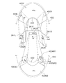
- FIG. 16 is an example of a display image.
- FIG. 16 shows an example of a display image displayed in the front car window image area 261F and the rearview mirror image area 262B of the front display 255F.
- the display image includes a front vehicle window image, a rearview mirror image, and a line-of-sight locus 283.
- the front car window image is displayed in the front car window image area 261F, and includes a car window image 280 through the front window 306F, a vehicle body image 281 of the front pillar 307F, and a vehicle body image 282 of the dashboard 301.
- the rearview mirror image is displayed in the rearview mirror image area 262B, and the line-of-sight locus 283 is displayed in the front vehicle window image area 261F and the rearview mirror image area 262B.
- the right display 255R displays the right vehicle window image, the right mirror image, and the line-of-sight locus
- the left display 255L displays the left vehicle window image, the left-side mirror image, and the line-of-sight locus.
- the display image includes not only the front vehicle window image of the own vehicle but also the right and left vehicle window images of the own vehicle. Accordingly, the viewer can grasp what kind of situation the driver is actually observing while viewing the displayed video on the display 255 of the driving education terminal 250. For example, the viewer can learn not only dangerous driving that occurs in front of the vehicle but also dangerous driving that occurs on the right and left sides. In this way, the viewer can learn about various situations where dangerous driving occurs by watching dangerous driving that occurs in various directions with respect to the driver. Can be performed effectively.
- the display image includes not only the vehicle window image but also the mirror image that the driver observes through the mirror. Therefore, the viewer of the display image can also grasp the rear and rear side conditions confirmed by the driver through the mirror.
- the viewer of the display image recognizes what object the driver has recognized other than the driver's own vehicle while traveling. You can see if you did not.
- the cause of dangerous driving can be analyzed, for example, because dangerous driving has occurred because the vehicle behind the vehicle has not been recognized, and can be used for safe driving education.
- the peripheral information acquired by each of the cameras 205a to 205d is converted into a display image based on the driver's viewpoint.
- the display image is an image based on the viewpoint of the driver, the viewer can view as if he / she is driving the vehicle.
- the viewer can view as if he / she encountered dangerous driving. Therefore, it is possible to provide effective safe driving education such as making a strong impression on the viewer about the situation in which dangerous driving has occurred and making it useful during actual driving.
- the various correspondence tables DB 130 stores all data used by the driving image processing apparatus 100 for calculation and determination.
- One example will be described below.
- the various correspondence table DB 130 stores the positional relationship between the front vehicle window video area 261F and the rearview mirror video area 262B. Similarly, the various correspondence table DB 130 stores the positional relationship between the right vehicle window image area 261R and the right mirror image area 262R. Further, the various correspondence tables DB 130 stores the positional relationship between the left car window image area 261L and the left mirror image area 262L.
- the various correspondence table DB 130 associates the coordinates of each pixel constituting each vehicle window video and each mirror video, and each coordinate of each video area on the display 255, among the video data acquired by each camera 205a to 205d. Is remembered.
- the various correspondence tables DB 130 may store associations between the coordinates of the pixels of the cameras 205 a to 205 d and the coordinates of the three-dimensional projection plane 400.
- the various correspondence table DB 130 stores associations between the coordinates on the three-dimensional projection surface 400 of the video data constituting each vehicle window video and each mirror video and the coordinates of each video area on the display 255. May be.
- the various correspondence table DB 130 stores the correspondence between the line-of-sight origin P and the line-of-sight vector, and the line-of-sight locus that is the coordinates on the display area of the display 255.
- these associations in the various correspondence table DB 130 are performed in consideration of distortion correction that is performed when, for example, video captured by the camera is converted into video on the display 255.
- the various correspondence table DB 130 may store the above-described various correspondences by, for example, mathematical formulas. For example, the positional relationship between the front car window image area 261F and the rearview mirror image area 262B is defined and stored by a mathematical expression.
- Driving Education Terminal Functional units of the driving education terminal 250 in FIG. 8 include, for example, a transmission / reception unit 270 and a display control unit 271.
- the driving education terminal 250 receives a display instruction for a desired display image from the viewer via the mouse 256 and the keyboard 257.
- the transmission / reception unit 270 outputs a display video display instruction to the display video generation unit 124 of the driving video processing device 100.
- the transmission / reception unit 270 receives a desired display video from the display video generation unit 124, and the display control unit 271 displays the display video on the display 255.
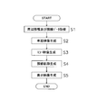
- FIG. 17 is a flowchart showing an example of a flow of processing executed by the driving image processing apparatus according to the first embodiment. This process is executed for each frame, for example.
- Step S1 The driving image processing apparatus 100 acquires peripheral information and line-of-sight data from the information acquisition apparatus 200 and stores them in the peripheral information DB 125 and line-of-sight data DB 129.
- Step S2 The vehicle window image generation unit 121 reads out the peripheral information from the peripheral information DB 125.
- the vehicle window image generation unit 121 uses the vehicle window images 400F, 400R, and 400L from the surrounding information based on the association between the vehicle window images 400F, 400R, and 400L and the vehicle window image regions 261F, 261R, and 261L on the display 255. Is generated. Further, the vehicle window image generation unit 121 refers to the vehicle body structure DB 128 and reads the vehicle body structure of the corresponding vehicle type.
- the vehicle window image generation unit 121 generates each vehicle window image 400F, 400R, 400L by further incorporating the vehicle body structure, and stores it in the vehicle window image DB 126.
- Step S3 The mirror video generation unit 122 reads the peripheral information from the peripheral information DB 125.
- the mirror video generation unit 122 generates a mirror video from the peripheral information based on the correspondence between the mirror videos 400MR, 400ML, and 400MB and the mirror video areas 262R, 262L, and 262B on the display 255. Further, the mirror video generation unit 122 generates each mirror video 400MB, 400MR, and 400MB by further incorporating the vehicle body structure read from the vehicle body structure DB 128 and stores it in the mirror video DB 127.
- Step S4 The line-of-sight locus generation unit 123 calculates the line-of-sight locus of the driver on the display area of the front display 255F, the right display 255R, and the left display 255L based on the line-of-sight origin P and the line-of-sight vector 150a of the line-of-sight data DB 129. .
- Step S5 The display image generation unit 124 combines the vehicle window image of the vehicle window image DB 126 and the mirror image of the mirror image DB 127 based on the positional relationship between each vehicle window image region and each mirror image region, and further superimposes the line-of-sight locus. Display image.
- FIG. 18 is a schematic diagram showing how the driver's line of sight changes according to the angle of the mirror.
- FIG. 18 shows an example in which the angle of the right door mirror 303R is changed as an example.
- the door mirror 303R1 is in an initial setting state, and the mirror angle at this time is 0 °.
- the line-of-sight vector 150a to the driver's door mirror 303R1 becomes the mirror line-of-sight vector 155a1 by the door mirror 303R1.
- the angle of the door mirror 303R2 is changed in the plus (+) direction by ⁇ MR ° from the initial setting state.
- the line-of-sight vector 150a to the driver's door mirror 303R2 becomes a mirror line-of-sight vector 155a2 by the door mirror 303R2.
- the mirror line-of-sight vector is changed from the mirror line-of-sight vector 155a1 to the mirror line-of-sight vector 155a2 by changing the mirror angle.
- FIG. 19 is an explanatory diagram showing the relationship between the vehicle window image and mirror image on the three-dimensional projection plane and the display area of each display.
- the mirror image on the three-dimensional projection surface 400 visible in the direction of the mirror line-of-sight vector 155a1 is the right-side mirror image 400MR1 in FIG.
- the mirror image on the three-dimensional projection surface 400 visible in the direction of the mirror line-of-sight vector 155a2 is the right-side mirror image 400MR2 in FIG. Therefore, the driving image processing apparatus 100 varies the correspondence between the coordinates of each pixel of each mirror image on the three-dimensional projection plane 400 and the coordinates of each mirror image area 262 according to the mirror angle.
- the coordinate Pe1 of the right mirror image 400MR1 is associated with the coordinate Pe1 'of the right mirror image region 262R.
- the coordinate Pe2 of the right mirror image 400MR2 is associated with the coordinate Pe2 'of the right mirror image region 262R.
- the visually recognizable image varies depending on the change in the mirror angle.
- the information acquisition device 200 detects a change in the mirror angle of the mirror 303 and outputs the change to the driving image processing device 100.
- the mirror video generation unit 122 changes the correspondence between the mirror video 400MR, 400ML, and 400MB and the mirror video areas 262R, 262L, and 262B on the display 255 according to the mirror angle.
- the various correspondence table DB 130 updates the association.
- the mirror video generation unit 122 generates the mirror video 400MR, 400ML, and 400MB, based on the updated association, the mirror video generation unit 122 converts the video data of each pixel constituting each mirror video to each mirror video on the display 255. Transform coordinates to the territory.
- both the vehicle window image and the mirror image are included in the display image.
- the display image may be generated by synthesizing either the vehicle window image or the mirror image and the line-of-sight locus.
- the driving image processing apparatus 100 of the second embodiment Similar to the driving image processing apparatus 100 of the first embodiment, the driving image processing apparatus 100 of the second embodiment generates a display image including a vehicle window image, a mirror image, and a line-of-sight locus.
- the driving image processing apparatus 100 according to the second embodiment reflects a recognition result as to whether or not the driver of the host vehicle recognizes an object included in the display image on the display image.
- a configuration different from that of the first embodiment will be described. First, an overview of the process will be described. Note that a modification of the first embodiment is also applicable to the second embodiment.
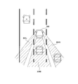
- the driving image processing apparatus 100 determines whether or not the driver of the host vehicle 300 has recognized an object that is a target of dangerous driving based on the line of sight 150 acquired by the line-of-sight detection device 206. To do. The outline of the processing by the driving image processing apparatus 100 will be described with reference to FIG.
- FIG. 20 is a perspective view showing the relationship between the host vehicle and another vehicle.
- the other vehicle 500 is traveling on the lane 601 adjacent to the left with respect to the lane 600 on which the host vehicle 300 travels.
- the driving image processing apparatus 100 can determine that the driver of the host vehicle 300 recognizes the other vehicle 500. Specifically, for example, the driving image processing apparatus 100 sets a line-of-sight space 151 centered on the line of sight 150 of the driver of the host vehicle 300, and at least one area of the other vehicle 500 that is the object in the line-of-sight space 151. It is determined whether or not it is recognized based on whether or not is included.
- the driving image processing apparatus 100 makes a determination based on an angle ⁇ formed by the line-of-sight vector 150a and the object vector 160a from the host vehicle 300 to the other vehicle 500.
- the line-of-sight space 151 is a space formed by a set of line-of-sight space lines 151a whose starting point is the line-of-sight origin P and whose angle ⁇ a formed with the line-of-sight vector 150a is equal to or smaller than a predetermined threshold ⁇ th.
- FIG. 21 is an example of a block diagram illustrating a functional configuration of each device according to the second embodiment.
- the video processing unit 131, the object extraction unit 132, the relative information calculation unit 133, the line-of-sight determination unit 134, the recognition determination unit 135, the relative information DB 136, and the recognition of the driving video processing device 100 A result DB 137 is provided.
- Each functional configuration will be described below. Other configurations are the same as those of the first embodiment.
- FIG. 22 is a schematic diagram showing a three-dimensional projection surface onto which a peripheral video is projected.
- the video processing unit 131 acquires a correspondence relationship between each pixel of each of the cameras 205a to 205d and each coordinate of the three-dimensional projection plane 400 from various correspondence table DBs 130.
- the video processing unit 131 projects the video data of each of the cameras 205a to 205d on the three-dimensional projection plane 400 based on the correspondence relationship of the coordinates, and generates a peripheral video.
- the object extraction unit 132 extracts one or more objects existing around the host vehicle 300 from the peripheral video generated by the video processing unit 131.
- FIG. 23 is an explanatory diagram showing an example of an object extraction method.
- the host vehicle 300 is traveling on the lane 600, and the other vehicle 500 that is the object is traveling on the lane 601 adjacent to the left.
- the object extraction unit 132 extracts edges based on, for example, the luminance contrast ratio in the surrounding video, and detects the lane display lines 602a to 602d.
- the object extraction unit 132 detects the vanishing point D from the intersection of the lane display lines 602a to 602d, and determines the search range of the object based on the vanishing point D.
- the search range can be determined as a range surrounded by the vanishing point D and the lane display lines 602a to 602d or a predetermined range including the range.
- the object extraction unit 132 extracts object candidates around the host vehicle 300 within the search range.
- An object candidate is a candidate that can be an object.
- the target object extraction unit 132 compares the target object candidate with the pattern data storing various characteristics of the target object stored in advance to determine whether or not the target object candidate is the target object. decide. For example, the object extraction unit 132 determines the object candidate as the object when the object candidate matches the pattern data of the vehicle. In the example of FIG. 23, the object extraction unit 132 extracts another vehicle 500 as the object. On the other hand, the object extraction unit 132 determines that the object candidate is not an object when the object candidate does not match the pattern data of the object.
- the object extraction unit 132 assigns an object number to each object in order to identify each extracted object, and acquires the relative position Q of the object with respect to the host vehicle 300.
- Examples of the relative position Q include coordinates of a portion of the target object that is closest to the host vehicle 300.
- the object extraction unit 132 acquires the right corner point Q of the other vehicle 500 as a relative position.
- the object extraction unit 132 acquires the left corner point of the other vehicle 500 as a relative position.
- the relative position Q is defined by a spatial coordinate system having an arbitrary center point O of the vehicle 300 as an origin.
- the object extraction unit 132 only needs to be able to grasp the position of the object, and the relative position of the object is not limited to the relative position Q described above.
- the object extraction unit 132 stores the object number and the relative position Q in the relative information DB 136.
- the relative information DB 136 stores the object number and the relative position Q acquired from the object extracting unit 132 for each frame and each object.
- the relative information DB 136 stores an object vector calculated by a relative information calculation unit 133 described later for each frame and each object.
- FIG. 24 is an example of the relative information DB.
- the relative information DB 136 stores, for example, a frame number, an object number, a relative position Q, and an object vector.
- the number of target objects increases or decreases.
- the line-of-sight data DB 129 acquires the line-of-sight origin P and the line-of-sight vector 150a of the driver of the host vehicle from the information acquisition device 200 and stores them.
- the line-of-sight data DB 129 stores the presence / absence of visual recognition of the mirror 303, the mirror line-of-sight origin R, and the mirror line-of-sight vector 155a, which are determined by the line-of-sight determination unit 134 described later. Further, the line-of-sight data DB 129 also stores the line-of-sight locus generated by the line-of-sight locus generation unit 123.
- the mirror line-of-sight origin R refers to the coordinates of the intersection of the line-of-sight vector 150a and the mirror surface area of the mirror 303. Further, the line of sight 150 from the driver is reflected by the mirror 303 to become a mirror line of sight 155.
- the mirror line-of-sight vector 155a is a vector indicating the direction of the mirror line-of-sight 155.
- the mirror line-of-sight origin R and the mirror line-of-sight vector 155a are defined by a spatial coordinate system centered on an arbitrary center point O of the host vehicle 300.
- FIG. 25 is an example of a line-of-sight data DB.
- the line-of-sight data DB 129 stores a frame number, a line-of-sight origin P, a line-of-sight vector 150a, mirror viewing Yes / NO, a mirror line-of-sight origin R, a mirror line-of-sight vector 155a, and a line-of-sight locus for each frame.
- (XD_1, YD_1, ZD_1) is stored as the visual line locus.
- the line-of-sight data DB 129 indicates that the line-of-sight origin P (Xv1, Yv1, Zv1), the line-of-sight vector Visual_6, “YES” indicating that the mirror 303 is visually recognized, and the mirror line-of-sight origin R (Xm1) , Ym1, Zm1), and the mirror line-of-sight vector Vmirror_6.
- (XD_6, YD_6, ZD_6) is stored as the line-of-sight locus.
- the relative information calculation unit 133 calculates an object vector.
- the object vector is a vector indicating the direction from the line-of-sight origin P or the mirror line-of-sight origin R to the object.
- the relative information calculation unit 133 acquires the line-of-sight origin P or the mirror line-of-sight origin R from the line-of-sight data DB 129. Specifically, the relative information calculation unit 133 acquires the line-of-sight origin P if the result of mirror viewing is “NO” in the line-of-sight data DB 129, and determines the mirror line-of-sight origin R if the result of mirror viewing is “YES”. get. In addition, the relative information calculation unit 133 acquires the relative position Q of the target object for which the target object vector is calculated from the relative information DB 136. Next, the relative information calculation unit 133 calculates an object vector 160a indicating a direction 160 from the line-of-sight origin P or the mirror line-of-sight origin R to the object.
- the object vector 160a is calculated as follows.
- the object vector 160a is calculated as follows.
- the relative position Q of the object is (X_26, Y_26, Z_26).
- the relative information calculation unit 133 calculates the object vector Vobject_26 based on the mirror line-of-sight origin R and the relative position Q.
- the object vector 160a may be defined by coordinates in the spatial coordinate system, or may be defined by an angle formed by the object vector 160a, the XY plane, and the YZ plane.
- the relative information calculation unit 133 stores the above calculation result in the relative information DB 136.
- the line-of-sight determination unit 134 includes a line-of-sight vector 150a or a mirror line-of-sight vector 155a, and an object vector 160a so that the presence or absence of recognition of the object by the driver of the host vehicle can be determined. Calculate the formed angle.
- the line-of-sight determination unit 134 determines whether or not the line-of-sight vector 150a is on the mirror 303 based on the line-of-sight origin P and the line-of-sight vector 150a of the line-of-sight data DB 129.
- the line-of-sight determination unit 134 acquires and grasps the areas of the mirror surfaces such as the left and right door mirrors 303L and 303R and the rearview mirror 303B provided in the host vehicle 300 from the information acquisition device 200, for example.
- the region of the mirror surface is a region of the reflecting surface that reflects incident light, and is defined by a set of coordinates based on a spatial coordinate system, for example.
- the line-of-sight determination unit 134 determines whether or not the line-of-sight vector 150a is on the mirror 303 based on whether or not the line-of-sight vector 150a extending from the line-of-sight origin P intersects the region of the mirror surface.
- the line-of-sight determination unit 134 sets the intersection point as the mirror line-of-sight origin R. Further, the line-of-sight determination unit 134 obtains the mirror line-of-sight vector 155a by reflecting the line-of-sight vector 150a from the mirror line-of-sight origin R with the mirror 303. The line-of-sight determination unit 134 stores the presence / absence of visibility of the mirror 303, the mirror line-of-sight origin R, and the mirror line-of-sight vector 155a in the line-of-sight data DB 129 as shown in FIG. When the position is changed by finely adjusting each mirror 303 or the like, the line-of-sight determination unit 134 acquires the mirror surface area after the change from the information acquisition apparatus 200, for example.
- the line-of-sight determination unit 134 calculates an angle formed by the line-of-sight vector 150a or the mirror line-of-sight vector 155a and the object vector 160a. The calculation method will be described below with reference to FIGS.
- FIG. 26 is an explanatory diagram showing an example of a method for calculating the angle ⁇ formed by the line-of-sight vector and the object vector.
- the host vehicle 300 is traveling on the lane 600, and the other vehicle 500 that is the object is traveling on the lane 601 adjacent to the left of the lane 600, and is located on the left front side with respect to the host vehicle 300.
- the line-of-sight determination unit 134 reads the line-of-sight origin P and the line-of-sight vector 150a when referring to the line-of-sight data DB 129 and determining that the mirror view is NO in the determination target frame.
- the line-of-sight determination unit 134 reads the object vector 160a for the determination target frame and the determination target object with reference to the relative information DB 136. Next, the line-of-sight determination unit 134 calculates an angle ⁇ formed by the driver's line-of-sight vector 150a starting from the line-of-sight origin P and the object vector 160a starting from the line-of-sight origin P. Here, the line-of-sight determination unit 134 calculates an angle ⁇ H formed by the line-of-sight vector 150a and the object vector 160a in the XY plane, as shown in FIG. Furthermore, the line-of-sight determination unit 134 calculates an angle ⁇ V formed by the line-of-sight vector 150a and the object vector 160a in the YZ plane, as shown in FIG.
- FIG. 27 is an explanatory diagram showing an example of a method for calculating the angle ⁇ formed by the mirror line-of-sight vector and the object vector.
- the own vehicle 300 is traveling on the lane 600, and the other vehicle 500 that is the object is traveling on the lane 603 adjacent to the right of the lane 600, and is located on the right rear side with respect to the own vehicle 300.
- the line-of-sight determination unit 134 reads the mirror line-of-sight origin R and the mirror line-of-sight vector 155a when referring to the line-of-sight data DB 129 and determining that mirror viewing is YES in the determination target frame. For example, it is assumed that the driver is viewing the right door mirror 303R of the host vehicle 300.
- the line-of-sight vector 150a starting from the line-of-sight origin P is reflected by the mirror 303R and becomes the mirror line-of-sight vector 155a starting from the mirror line-of-sight origin R.
- the line-of-sight determination unit 134 reads the object vector 160a for the determination target frame and the determination target object with reference to the relative information DB 136.
- the line-of-sight determination unit 134 calculates an angle ⁇ formed by the mirror line-of-sight vector 155a starting from the mirror line-of-sight origin R and the object vector 160a starting from the mirror line-of-sight origin R. In other words, the line-of-sight determination unit 134, as shown in FIGS.
- FIG. 6A and 6B shows the angle ⁇ H formed by the mirror line-of-sight vector 155a and the object vector 160a in the XY plane, and the mirror line-of-sight in the YZ plane.
- An angle ⁇ V formed by the vector 155a and the object vector 160a is calculated.
- the line-of-sight determination unit 134 stores the formed angles ⁇ H and ⁇ V in the recognition result DB 137 as determination results.
- FIG. 28 is an example of a recognition result DB.
- the recognition result DB 137 stores, for example, the frame number, the object number, the angle formed by the line of sight and the object, and the presence / absence of recognition determined by the recognition determination unit 135 for each object for each frame.
- the recognition determination unit 135 determines that the driver does not recognize the object, “NO” is stored.
- the recognition determination unit 135 determines whether or not the driver of the host vehicle 300 recognizes the object. For example, the recognition determination unit 135 determines the presence / absence of recognition based on the positional relationship between the line-of-sight space 151 illustrated in FIG. 20 and the other vehicle 500 that is the target. For example, the recognition determination unit 135 determines whether or not the object is located at the center of the line-of-sight space 151. If the object is located at the center of the line-of-sight space, the line of sight 150 and the object intersect. It is determined that the object is recognized.
- the recognition determination unit 135 determines what percentage of the target object occupies the line-of-sight space 151, and whether or not the target object is recognized according to the degree to which the target object area occupies the line-of-sight space 151. May be determined. The determination method will be described in more detail.
- the recognition determination unit 135 reads the angles ⁇ H and ⁇ V formed for the object of the determination target frame from the recognition result DB.
- the recognition determination unit 135 compares predetermined threshold values ⁇ Hth and ⁇ Vth for determining whether or not the object is recognized with the formed angles ⁇ H and ⁇ V, and the driver recognizes the object. Judge whether or not.
- the threshold ⁇ th includes a predetermined threshold ⁇ Hth for determining an angle ⁇ H formed in the XY plane and a predetermined threshold ⁇ Vth for determining an angle ⁇ V formed in the YZ plane. Therefore, the recognition determination unit 135 determines whether or not the formed angle ⁇ H is equal to or smaller than the predetermined threshold ⁇ Hth, and further determines whether or not the formed angle ⁇ V is equal to or smaller than the predetermined threshold ⁇ Vth.
- the driver of the host vehicle 300 visually recognizes the object. It is determined that the object is recognized.
- the recognition determining unit 135 It is determined that it was not recognized.
- the recognition determination unit 135 determines the presence / absence of recognition based on both of the angles ⁇ H and ⁇ V formed. However, for example, the presence / absence of recognition based on the angle formed by one of the angles ⁇ H and ⁇ V. Can also be determined.
- the recognition determination unit 135 stores the determination result in the recognition result DB 137 of FIG.
- the display video generation unit 124 reads out the vehicle window video in the vehicle window video DB 126 and the mirror video in the mirror video DB 127 for the display video generation target frame. Further, the display video generation unit 124 reads the line-of-sight locus of the corresponding frame from the line-of-sight data DB 129. Further, the display video generation unit 124 reads out the positional relationship between each vehicle window video area and each mirror video area from the various correspondence table DB 130.
- the display image generation unit 124 combines the vehicle window image and the mirror image of the corresponding frame based on the positional relationship between each vehicle window image region and each mirror image region, and further generates a display image by superimposing the line-of-sight locus.
- the display image generation unit 124 reads the relative position Q of each object existing in the corresponding frame from the relative information DB 136 and reads the presence / absence of recognition of each object in the corresponding frame from the recognition result DB 137.
- the display video generation unit 124 reflects the presence / absence of recognition based on the relative position Q of each object in the display video on the display video obtained by combining the vehicle window video, the mirror video, and the line-of-sight locus.
- the relative position Q is defined by a spatial coordinate system having an arbitrary center point O of the vehicle 300 as an origin. Therefore, the display video generation unit 124 converts the relative position Q into the coordinates of the display area on the display 255.
- the correspondence table DB 130 stores associations between the coordinates in the spatial coordinate system and the coordinates of the display area on the display 255.
- the display video generation unit 124 performs video processing according to the presence or absence of recognition of each object based on the coordinates of the display area of each object. For example, if the target object is not recognized, the display video generation unit 124 displays “x” in a frame surrounding the target object, and if the target object is recognized, performs a process of simply surrounding the target object with the frame. Alternatively, “recognition” or “no recognition” may be displayed.
- FIG. 29 is an example of a display image.
- a frame and “x” are displayed on the other vehicle as the object.
- the display image includes a front vehicle window image, a rearview mirror image, and a line-of-sight locus 283.
- the front car window image is displayed in the front car window image area 261F, and includes a car window image 280 through the front window 306F, a vehicle body image 281 of the front pillar 307F, and a vehicle body image 282 of the dashboard 301.
- the rearview mirror image is displayed in the rearview mirror image area 262B, and the line-of-sight locus 283 is displayed in the front vehicle window image area 261F and the rearview mirror image area 262B.
- two other vehicles 500a and 500b traveling in front of the host vehicle 300 are displayed as objects.
- a frame surrounding the other vehicle 500a is displayed on the other vehicle 500a, and “x” is displayed in the frame on the other vehicle 500b.
- a line-of-sight locus 283 is hung on a part of the other vehicle 500a, and the driver of the host vehicle 300 may recognize the other vehicle 500a.
- the line-of-sight locus 283 is not applied to the other vehicle 500b, the driver may not recognize the other vehicle 500b.
- the right display 255R displays the right vehicle window image, right mirror image, line-of-sight locus, and presence / absence of recognition
- the left display 255L displays the left vehicle window image, left mirror image, line-of-sight locus, and presence / absence of recognition.
- the viewer of the display image can immediately determine whether or not the driver has recognized the object. . Also, based on the presence or absence of recognition, the cause of dangerous driving can be analyzed and used for safe driving education.
- the driving image processing apparatus 100 determines whether or not the object is recognized based on the positional relationship between the actual line-of-sight direction of the driver of the host vehicle 300 and the objects around the host vehicle 300. Therefore, the accuracy of determination can be improved.
- FIG. 30 is a flowchart showing an example of the flow of overall processing executed by the driving video processing apparatus according to the second embodiment. This entire process is executed for each frame, for example.
- Step S11 The driving image processing apparatus 100 acquires peripheral information and line-of-sight data from the information acquisition apparatus 200, and stores them in the peripheral information DB 125 and the line-of-sight data DB 129.
- Step S12 The driving image processing apparatus 100 performs a recognition determination process described later.
- Steps S13 to S15 The driving image processing apparatus 100 generates a vehicle window image, a mirror image, and a line-of-sight trajectory, respectively, similarly to steps S2 to SS4 of FIG. 17 of the first embodiment.
- Step S16 The display image generation unit 124 combines the vehicle window image of the vehicle window image DB 126 and the mirror image of the mirror image DB 127 based on the positional relationship between each vehicle window image region and each mirror image region, and further superimposes the line-of-sight locus. To do.
- the display video generation unit 124 determines whether or not the recognition result DB 137 recognizes the object on the display image obtained by combining the vehicle window image, the mirror image, and the line-of-sight locus based on the relative position Q of each object in the relative information DB 136. reflect.
- FIG. 31 is a flowchart illustrating an example of the flow of recognition determination processing according to the second embodiment. First, the entire recognition determination process will be described, and then each process of the recognition determination process will be described.
- Step S20 The driving image processing apparatus 100 performs a mirror process on the line-of-sight data depending on whether or not the driver is viewing the mirror.
- Step S21 The driving image processing apparatus 100 performs an object extraction process for extracting one or a plurality of objects existing around the host vehicle 300.
- Step S22 The driving image processing apparatus 100 performs recognition presence / absence determination processing for determining whether or not the driver recognizes the object.
- FIG. 32 is a flowchart showing an example of the flow of gaze data mirror processing according to the second embodiment.
- Step S20a The line-of-sight determination unit 134 determines whether the line-of-sight vector 150a is on the mirror 303 based on the line-of-sight origin P and the line-of-sight vector 150a. If the line-of-sight vector 150a is on the mirror 303, the process proceeds to step S20b, and if not, the process ends.
- Steps S20b and S20c The line-of-sight determination unit 134 sets the mirror line-of-sight origin R (S20b) and calculates the mirror line-of-sight vector 155a (S20c).
- FIG. 33 is a flowchart showing an example of the flow of object extraction processing according to the second embodiment.
- Step S21a The video processing unit 131 projects the video data of each of the cameras 205a to 205d on the three-dimensional projection plane 400 for the current frame to generate a peripheral video.
- Steps S21b and S21c The object extraction unit 132 extracts edges in the peripheral video generated by the video processing unit 131 (S21b), and detects the lane display lines 602a to 602d (S21c).
- Steps S21d, S21e Next, the object extraction unit 132 detects the vanishing point D from the intersection of the lane display lines 602a to 602d (S21d), and determines the search range of the object based on the vanishing point D (S21e). ).
- Step S21f The object extraction unit 132 extracts object candidates from the search range.
- Steps S21g, S21h The object extraction unit 132 performs pattern matching on the object candidates (S21g), and extracts the objects (S21h).
- Step S21i When the object is extracted, the process proceeds to step S21j, and when the object is not extracted, the process ends.
- Step S21j The object extraction unit 132 confirms the identity with the object one frame before and assigns an object number. For example, the identity is confirmed as follows.
- the object extraction unit 132 compares peripheral images of the previous frame and the current frame, and determines that objects having high similarity are the same object between frames.
- the object extraction unit 132 predicts the position in the current frame based on the speed, distance, traveling direction, and the like for the object detected one frame before.
- the object extraction unit 132 determines that the object existing at the predicted position in the current frame is the same as the object one frame before.
- Step S21k The object extraction unit 132 acquires the relative position Q of each object with respect to the host vehicle 300, and stores it in the relative information DB 136. Further, the relative information calculation unit 133 calculates an object vector 160a indicating the direction 160 from the line-of-sight origin P or the mirror line-of-sight origin R to the object, and stores it in the relative information DB 136.
- FIG. 34 is a flowchart showing an example of the flow of recognition presence / absence determination processing according to the second embodiment.
- Step S22a The line-of-sight determination unit 134 refers to the line-of-sight data DB 129 and determines whether or not the mirror 303 is visually recognized based on whether or not the line-of-sight vector is on the mirror 303 in the current frame. If the mirror 303 is visually recognized, the process proceeds to step S22d. If not, the process proceeds to step S22b.
- Step S22b The line-of-sight determination unit 134 reads the line-of-sight origin P and the line-of-sight vector 150a from the line-of-sight data DB 129 when the mirror 303 is not visually recognized.
- Step S22c The line-of-sight determination unit 134 selects an object to be determined, and reads the object vector 160a from the relative information DB 136. Next, the line-of-sight determination unit 134 calculates angles ⁇ H and ⁇ V formed by the line-of-sight vector 150a starting from the line-of-sight origin P and the object vector 160a starting from the line-of-sight origin P, and stores them in the recognition result DB 137. .
- Step S22d The line-of-sight determination unit 134 reads the mirror line-of-sight origin R and the mirror line-of-sight vector 155a from the line-of-sight data DB 129 when viewing the mirror 303.
- Step S22e The line-of-sight determination unit 134 selects an object to be determined, and reads the object vector 160a from the relative information DB 136. Next, the line-of-sight determination unit 134 calculates angles ⁇ H and ⁇ V formed by the mirror line-of-sight vector 155a starting from the line-of-sight origin R and the object vector 160a starting from the mirror line-of-sight origin R, and the recognition result DB 137 Store.
- Step S22f The recognition determination unit 135 determines whether or not the formed angles ⁇ H and ⁇ V are equal to or less than the threshold values ⁇ Hth and ⁇ Vth.
- Step S22g When the formed angle ⁇ H is equal to or smaller than the predetermined threshold ⁇ Hth and the formed angle ⁇ V is equal to or smaller than the predetermined threshold ⁇ Vth, the driver of the host vehicle 300 visually recognizes the object, Judge that it was recognized.
- Step S22h On the other hand, the recognition determination unit 135 determines that the driver has not recognized the object when the formed angle ⁇ H is larger than the predetermined threshold ⁇ Hth or when the formed angle ⁇ V is larger than the predetermined threshold ⁇ Vth. To do.
- Steps S22i, 22j The recognition determination unit 135 ends the process if the above determination is completed for all the objects in the current frame (S22i). Otherwise, the next object is selected (S22j), and the process returns to step S22a.
- the driving image processing apparatus 100 generates a display image that reflects the degree of object recognition and / or the risk of collision.
- the recognition degree of an object is an index indicating how much the driver recognizes the object. Note that it is unclear whether the driver knows the information related to the object as described above simply by visually recognizing the object, and therefore, visual recognition and recognition are distinguished here.
- the risk level is an index indicating the degree of risk of collision between the host vehicle 300 and the target object.
- the relative information DB 136 stores the object number and the relative position Q acquired from the object extracting unit 132 for each frame and each object.
- the relative information DB 136 stores the relative distance L, the relative speed V, the TTC (Time To Collision), the target object vector 160a, and the like calculated by the relative information calculation unit 133 for each frame and each target object.
- FIG. 35 is an example of a relative information DB.
- the relative information DB 136 stores, for example, a frame number, an object number, a relative position Q, a relative distance L, a relative speed V, a TTC, and an object vector 160a.
- the relative distance L includes a relative distance Lx in the X direction and a relative distance Ly in the Y direction.
- the relative speed V includes a relative speed Vx in the X direction and a relative speed Vy in the Y direction.
- the TTC is an expected time required until the target object and the host vehicle 300 collide with each other, and includes an X-direction TTCx and a Y-direction TTCy.
- the relative information calculation unit 133 calculates relative information such as a relative distance L, a relative speed V, a TTC, and an object vector 160a between the host vehicle 300 and one or more objects. To do. A method for calculating the relative distance L, the relative speed V, and the TTC will be described again with reference to FIG.
- the relative distance Lx ′ and the relative distance Ly ′ in the Y direction are distances including half of the vehicle width of the host vehicle 300 and half of the vehicle length. Therefore, the relative information calculation unit 133 calculates the relative distance Lx by subtracting Lxcar, which is half of the vehicle width in the X direction, of the host vehicle 300 from the relative distance Lx ′. Similarly, the relative information calculation unit 133 calculates the relative distance Ly by subtracting Lycar, which is half the vehicle length of the host vehicle 300 in the Y direction, from the relative distance Ly ′.
- FIG. 36 is an explanatory diagram showing an example of a method for calculating the relative distance L. It is assumed that the camera 205 that captures a peripheral image of the host vehicle 300 is provided on the vehicle body above the center point O of the host vehicle 300. The height of the camera 205 from the ground is H, the focal length of the lens of the camera 205 is f, and the coordinates of the vanishing point D are (XD, YD, ZD).
- the relative information calculation unit 133 calculates the relative distance Lx ′ and the relative distance based on the following equations (1) and (2).
- the distance Ly ′ is calculated.
- Relative distance Ly ′ f ⁇ H /
- Relative distance Lx ′ Ly ′ ⁇ f /
- the relative information calculation unit 133 calculates the relative distance Lx and the relative distance Ly in the same manner as described above based on the relative distance Lx ′ and the relative distance Ly ′, and Lxcar and Lycar, and stores them in the relative information DB 136. Thereby, it is possible to calculate the relative distance Lx and the relative distance Ly in the current frame of interest.
- the relative information calculation unit 133 calculates the relative distance of the target object in the previous frame immediately before the current frame. Obtain Ly and relative distance Lx. That is, the relative information calculation unit 133 calculates the difference in the relative distance L between the previous frame and the current frame for the same object number. Next, the relative information calculation unit 133 calculates the relative velocity Vy in the Y direction based on the difference in the relative distance Ly between the current frame and the previous frame and the time between frames. Similarly, the relative information calculation unit 133 calculates the relative velocity Vx in the X direction based on the difference in the relative distance Lx between the current frame and the previous frame and the time between frames.
- the relative information calculation unit 133 calculates the TTC required until the target object and the host vehicle 300 collide based on the relative distance L and the relative speed V. For example, assuming that the object and the host vehicle 300 move at a constant speed, the TTC can be calculated based on the following equation (3).
- TTC relative distance / relative speed (3)
- the relative information calculation unit 133 acquires the relative distances Lx and Ly and the relative velocities Vx and Vy from the relative information DB 136.
- the relative information calculation unit 133 calculates the TTCx in the X direction and the TTCy in the Y direction based on the equation (3).
- the relative information calculation unit 133 calculates the TTC based on the equation (3) on the assumption that the object and the host vehicle 300 move at a constant speed, but calculates the TTC further considering the relative acceleration and the like. You may do it.
- the line-of-sight determination unit 134 calculates the mirror line-of-sight origin R and the mirror line-of-sight vector 155a as in the second embodiment. In addition, the line-of-sight determination unit 134 calculates angles ⁇ V and ⁇ H formed by the line-of-sight vector 150a or the mirror line-of-sight vector 155a and the object vector 160a.
- the line-of-sight determination unit 134 of the present modification determines whether or not the object is visually recognized based on the formed angles ⁇ V and ⁇ H.
- the method for determining the presence / absence of visual recognition is the same as the method in which the recognition determination unit 135 determines whether the object is recognized in the second embodiment. Note that the recognition determination unit 135 determines the risk of collision and / or the recognition of the object.
- the line-of-sight determination unit 134 visually recognizes the other vehicle 500 that is the target object. It is determined that it was. On the other hand, the line-of-sight determination unit 134 determines that the driver has not visually recognized the other vehicle 500 when the formed angle ⁇ H is larger than the predetermined threshold ⁇ Hth or when the formed angle ⁇ V is larger than the predetermined threshold ⁇ Vth.
- the presence / absence of visual recognition is determined based on both ⁇ H and ⁇ V. For example, the presence / absence of visual recognition can also be determined based on one of ⁇ H.
- the line-of-sight determination unit 134 stores the formed angles ⁇ H and ⁇ V and the presence / absence of visual recognition in the recognition result DB 137 as determination results.
- FIG. 37 and 38 are examples of the recognition result DB.
- FIG. 38 is an example of the viewing time and non-viewing time stored in the recognition result DB.
- the recognition result DB 137 in FIG. 37 stores, for each frame and each object, the TTCx and TTCy calculated by the relative information calculation unit 133, the angles ⁇ H and ⁇ V formed by the line-of-sight determination unit 134, and the presence or absence of visual recognition. .
- recognition result DB137 memorize
- the recognition result DB 137 of FIG. 38 stores the calculation results of the viewing time and the non-viewing time.
- the line-of-sight determination unit 134 of the present modification may further calculate the viewing time and the non-viewing time of each object in order to be used for determination of the degree of recognition described later.
- the line-of-sight determination unit 134 refers to the recognition result DB 137 of FIG. 37 and calculates the viewing time and non-viewing time for the same object.
- the presence or absence of visual recognition in each frame is indicated by YES and NO for each object number.
- the line-of-sight determination unit 134 calculates the visual recognition time by adding the frame time ⁇ tf by the number of continuous frames when the target object is visually recognized in the continuous frames. Similarly, the line-of-sight determination unit 134 calculates the non-visual time by adding the frame time ⁇ tf by the number of frames that are not visually recognized. Note that a frame time of one frame is ⁇ tf.
- the recognition determination unit 135 calculates a collision risk level and / or a recognition level of an object.
- the recognition determination unit 135 calculates the risk of collision between the target object and the host vehicle 300 based on the relative information in the relative information DB 136. For example, the recognition determination unit 135 calculates the risk level as follows.
- the recognition determination unit 135 calculates the risk level based on the TTC in the relative information DB 136.
- FIG. 39 is an example of a correspondence table showing the relationship between TTC and risk level.
- TTC is classified into 10 levels according to the degree of risk. For example, when the TTCx is 30 seconds, the recognition determination unit 135 determines that the risk in the X direction is “3”, and when the TTCy is 6 seconds, the risk determination in the Y direction is calculated as “9”. Furthermore, the recognition determination unit 135 may use the respective risk levels of TTCx and TTCy as the risk level of the target object. For example, the higher risk level in the X direction and the Y direction may be used as the risk level of the target object. You may set the risk level in the frame.
- the recognition determination part 135 calculates the recognition degree with respect to the target object of the driver of the own vehicle 300, and stores it in recognition result DB137.
- the recognition determination unit 135 can calculate the degree of recognition by, for example, the following methods (i) to (vi).
- the calculation method is an example and is not limited to the following.
- the recognition determination unit 135 determines the degree of recognition based on the positional relationship between the gaze space 151 illustrated in FIG. 20 and the other vehicle 500 that is the target. For example, the recognition determination unit 135 determines whether or not the object is located at the center of the line-of-sight space 151. If the object is located at the center of the line-of-sight space, the line of sight 150 and the object intersect. It is determined that the recognition degree of the object is high. In addition, the recognition determination unit 135 determines what percentage of the object occupies the gaze space 151, and if the object region occupies the gaze space 151, the recognition degree of the object is high. judge.
- the various correspondence tables DB 130 holds in advance the relationship between the position of the object relative to the line-of-sight space 151 and the degree of recognition, the ratio of the object included in the line-of-sight space 151, the degree of recognition, and the like. Shall.
- the recognition determination unit 135 determines the degree of recognition according to the magnitude of the angle ⁇ formed by the line-of-sight vector 150a or the mirror line-of-sight vector 155a and the object vector 160a.
- FIG. 40 is an example of a correspondence table showing the relationship between the formed angles ⁇ H and ⁇ V and the degree of recognition. Six levels of recognition of 0 to 5 are associated with predetermined ranges of ⁇ H and ⁇ V.
- the recognition determination unit 135 acquires ⁇ H and ⁇ V from the recognition result DB 137 of FIG. 37, and determines the degree of recognition with reference to the correspondence table shown in FIG.
- the recognition determination unit 135 determines the recognition level to be the highest level “5”. At this time, the driver's line of sight 150 is directly directed to the object, and it is considered that the driver is surely recognizing the object. Further, when the degree of recognition based on ⁇ H is different from the degree of recognition based on ⁇ V, the recognition determination unit 135 determines the recognition degree based on the lower level. For example, when the degree of recognition based on ⁇ H of 5 ° is 5 and the degree of recognition based on ⁇ V of 1 ° is 3, the degree of recognition may be determined as “3”.
- the recognition determination unit 135 determines the recognition level to be “0” at the lowest level.
- the recognition determination unit 135 determines the degree of recognition according to the length of the viewing time.
- the various correspondence tables DB 130 stores a correspondence table between the length of the visual recognition time and the degree of recognition, and in the correspondence table, for example, the degree of recognition is set higher as the visual recognition time becomes longer.
- the recognition determination unit 135 reads the viewing time from the recognition result DB 137 of FIG. 38 and determines the recognition level based on the correspondence table.
- the recognition determination unit 135 determines the degree of recognition based on the length of the non-viewing time.
- the various correspondence tables DB 130 stores a correspondence table between the length of the non-viewing time and the degree of recognition, and the degree of recognition is set lower in the correspondence table, for example, as the non-viewing time becomes longer.
- the recognition determination unit 135 reads the non-viewing time from the recognition result DB 137 and determines the degree of recognition based on the correspondence table.
- the recognition determination unit 135 may determine the degree of recognition according to both the viewing time and the non-viewing time. For example, even if the recognition determination unit 135 determines the recognition degree to be high once based on the long viewing time, if the non-viewing time after the viewing time ends is long, the recognition determination unit 135 sets the recognition degree according to the non-viewing time. Judge low.
- the recognition determination unit 135 may determine the degree of recognition for each object based on whether or not the non-viewing time is less than TTC, which is a predicted time until the host vehicle and each object collide. .
- the recognition determination unit 135 decreases the degree of recognition of the object when the non-viewing time is TTC or more. On the other hand, when the non-viewing time is shorter than TTC, the recognition determination unit 135 increases the degree of recognition of the object.
- the recognition determination unit 135 may determine the degree of recognition based on the moving speed when the line of sight 150 moves in the plurality of line-of-sight spaces 151. For example, the recognition determining unit 135 increases the degree of recognition when the moving speed is equal to or higher than a predetermined value Va, and decreases the degree of recognition when the moving speed is lower than the predetermined value Va.
- the recognition determination unit 135 may determine the degree of recognition for each object based on the visual frequency that each of the visual recognition times of the plurality of objects occupies within the predetermined time Ta. Moreover, the recognition determination part 135 may determine the recognition degree with respect to each target object based on the visual recognition interval with respect to each of a plurality of target objects.
- FIG. 41 is an explanatory diagram illustrating a method for determining the degree of recognition based on the viewing frequency or the viewing interval. It is assumed that the object A, the object B, and the object C are extracted as the objects, and the driver of the host vehicle 300 is visually recognizing the objects A to C. In FIG. 36, the visual recognition times ta, tb, and tc of the objects A to C are shown on the time axis t.
- the recognition determination unit 135 counts the frequency of visual recognition of each of the objects A to C within a predetermined time Tall. For example, the recognition determination unit 135 determines the degree of recognition to be higher as the frequency of visual recognition of each object is higher.
- the recognition determining unit 135 calculates the visual recognition intervals ⁇ T1, ⁇ T2, and ⁇ T3 of the objects A to C, and determines the recognition degree based on the visual recognition intervals ⁇ T1 to ⁇ T3. For example, the recognition determining unit 135 determines the degree of recognition based on whether or not the visual recognition intervals ⁇ T1 to ⁇ T3 are appropriate time intervals in which the objects A to C can be visually recognized.
- the visual recognition interval is calculated by, for example, the time between the intermediate points of the visual recognition times.
- the recognition determination unit 135 can determine whether or not the driver can recognize a plurality of objects.
- the recognition determination unit 135 determines the driver's degree of recognition based on a ratio between the number of objects around the host vehicle 300 and the number of objects determined to be visually recognized among the objects around the host vehicle 300. You may judge. The degree of recognition of a plurality of objects existing around the host vehicle 300 can be determined as a whole.
- the display image generation unit 124 synthesizes the vehicle window image, the mirror image, and the line-of-sight locus as in the second embodiment. Further, the display video generation unit 124 reads the relative position Q of each object existing in the corresponding frame from the relative information DB 136, and reads the degree of recognition and / or the degree of risk for each object of the corresponding frame from the recognition result DB 137. The display image generation unit 124 reflects the degree of recognition and / or risk based on the relative position Q of each object in the display image obtained by combining the vehicle window image, the mirror image, and the line-of-sight locus.
- the display video generation unit 124 converts the relative position Q into coordinates on the display area of the display 255, and performs video processing according to the degree of recognition and / or risk of each target based on the coordinates of each target. Apply. For example, the display video generation unit 124 highlights the target object as the degree of recognition is lower and / or the risk level is higher, or performs additional highlighting on the target object. Moreover, you may incorporate the numerical value of a recognition degree and / or a risk degree into an image
- the display video generation unit 124 may generate a display video by differentiating the display of an object that exists in the blind spot of the host vehicle 300 and an object that exists in a place other than the blind spot of the host vehicle 300.
- the blind spot is an area in which it is difficult for the driver to check the situation around the host vehicle 300.
- the blind spot is reflected on the mirror 303 or the like, which is an area that is difficult to see due to being blocked by the body of the host vehicle 300. There is no diagonally backward area or the like. Therefore, the driver cannot recognize the object or delays recognition when the object exists in the blind spot. Therefore, the display video generation unit 124 changes the display of the object depending on whether the object exists in the blind spot. Thereby, it can be used for analysis of a driving
- the relative information calculation unit 133 further determines whether or not an object around the host vehicle exists in the blind spot of the host vehicle 300.
- the relative information calculation part 133 shall hold
- the blind spot region can be defined by, for example, a set of coordinates in a spatial coordinate system.
- the relative information calculation unit 133 acquires the relative position Q from the relative information DB 136 for the determination target frame and the target object, and compares it with the blind spot area to determine whether the target object exists in the blind spot.
- the display video generation unit 124 displays differently the target object existing in the blind spot and the target object other than the blind spot in the display video. For example, the display video generation unit 124 highlights the target object that exists in the blind spot, or performs additional highlighting on the target object. Thereby, for example, the viewer of the display image can immediately determine whether the target object exists in the blind spot and the driver should pay attention.
- both the display result of the presence / absence of recognition of the object and the display result of whether or not the object exists in the blind spot are reflected in the display image, the viewer comprehensively displays these display results. It is possible to immediately determine whether or not the driver has recognized the blind spot object. Such a determination result is useful for analyzing the cause of the dangerous driving.
- the driving video processing apparatus 100 extracts one or a plurality of objects existing around the host vehicle 300 from the peripheral video generated by the video processing unit 131.
- the driving image processing apparatus 100 may detect an object using an obstacle detection sensor attached to the host vehicle 300, for example.
- the obstacle detection sensor is embedded in, for example, a front bumper, a rear bumper, or the like of the host vehicle 300 and detects a distance from the obstacle, and can be configured by an optical sensor, an ultrasonic sensor, or the like.
- the object extraction unit 132 of the driving image processing apparatus 100 detects an object around the host vehicle 300 based on the sensor signals detected by these obstacle detection sensors, and determines the relative position Q of the object with respect to the host vehicle 300. get.
- the relative information calculation unit 133 calculates the relative distance L, the relative speed V, the object vector 160a, and the like based on the sensor signal.
- the driving image processing apparatus 100 may detect the object based on communication between the host vehicle 300 and the object. Examples of the communication include inter-vehicle communication, which is communication between vehicles.
- the object extraction unit 132 of the driving image processing apparatus 100 detects an object around the host vehicle 300 based on the communication, and acquires a relative position Q of the object with respect to the host vehicle 300 and the like. Further, the relative information calculation unit 133 calculates a relative distance L, a relative speed V, an object vector 160a, and the like based on the communication.
- the driving image processing apparatus 100 according to the first embodiment acquires peripheral information and line-of-sight data around the host vehicle from the external information acquisition apparatus 200.
- the driving image processing apparatus 100 according to the third embodiment acquires these pieces of information by itself.
- FIG. 42 is an example of a block diagram illustrating a hardware configuration of the driving video processing device according to the third embodiment.
- the driving image processing apparatus 100 includes, for example, a CPU 101, a ROM 102, a RAM 103, an input / output device I / F 104, and a communication I / F 108. These are connected to each other via a bus 109.
- the input / output device I / F 104 is connected to input / output devices such as the display 105, the mouse 106, the keyboard 107, the peripheral information acquisition device 205, and the line-of-sight detection device 206.
- a computer program that causes a computer to execute the above-described method and a computer-readable recording medium that records the program are included in the scope of the present invention.
- the computer-readable recording medium for example, a flexible disk, a hard disk, a CD-ROM (Compact Disc-Read Only Memory), an MO (Magneto Optical disk), a DVD, a DVD-ROM, a DVD-RAM (DVD-RAM). Random Access Memory), BD (Blue-ray Disc), USB memory, semiconductor memory, and the like.
- the computer program is not limited to the one recorded on the recording medium, and may be transmitted via an electric communication line, a wireless or wired communication line, a network represented by the Internet, or the like.
- Driving image processing device 121 Car window image generation unit 122: Mirror image generation unit 123: Gaze locus generation unit 124: Display video generation unit 125: Peripheral information DB 126: Car window video DB 127: Mirror video DB 128: Body structure DB 129: Gaze data DB 130: Various correspondence table DB 131: Video processing unit 132: Object extraction unit 133: Relative information calculation unit 134: Gaze determination unit 135: Recognition determination unit 136: Relative information DB 137: Recognition result DB 150a: Gaze vector 151: Gaze space 155a: mirror line-of-sight vector 160a: object vector 200: Information acquisition device 205: Peripheral information acquisition device 206: Line-of-sight detection equipment 250: Terminal for driving education 255: Display 261F: Front car window image area 261R: Right car window image area 261L: Left car window image area 262R: Right mirror image area 262L: Left mirror image area 262B: Rearview mirror image area 255:
Landscapes
- Engineering & Computer Science (AREA)
- Computer Graphics (AREA)
- Computer Hardware Design (AREA)
- General Engineering & Computer Science (AREA)
- Software Systems (AREA)
- Physics & Mathematics (AREA)
- General Physics & Mathematics (AREA)
- Theoretical Computer Science (AREA)
- Mechanical Engineering (AREA)
- Traffic Control Systems (AREA)
Abstract
車両の運転者を教育するための映像を生成する映像処理装置、映像処理方法及び映像処理プログラムを提供することを目的とする。自車両の運転者が観察可能な、前記自車両に対して前方と右側及び/又は左側とにおける観察映像を、前記自車両の周辺映像に基づいて生成する車窓映像生成部121及びミラー映像生成部122と、前記観察映像に対する、前記運転者の視線軌跡を生成する視線軌跡生成部123と、前記観察映像に前記視線軌跡を重畳し、表示映像を生成する表示映像生成部124と、を含む、映像処理装置を提供する。これにより、車両の運転者を教育するための映像を生成する映像処理装置を得ることができる。
Description
本発明は、車両の運転者を教育するための映像を生成する映像処理装置、映像処理方法及び映像処理プログラムに関する。
車社会において安全を促進させて事故数を減少させることが大きな課題となっており、様々な対策がなされている。例えば、対策の1つとして、どのような場合に事故が生じやすいのかを映像を用いて運転者に学習させる方法がある。具体的には、例えば、特許文献1に記載のシステムのように、車両に搭載したドライブレコーダにより事故映像を取得し、その事故映像を再生して交通安全教育に役立てる。例えば、ドライブレコーダは、衝突事故における衝撃、あるいは、急ブレーキ及び急なハンドル操作などの危険運転を検出すると、自車両の前方映像及び自車両の走行状態を記録する。
しかし、上記のようなドライブレコーダが取得した映像を交通安全教育に用いる場合、運転者は、危険運転が生じた状況について、自車両の前方映像しか確認することができない。
図43は運転の様子の一例であり、図44はドライブレコーダが取得した図43の運転の映像である。図43では、自車両300が車線600上を走行している。他車両500は、車線600に隣接する車線601上を走行しており、自車両300の右斜め後ろに位置している。例えば、自車両300の運転者が他車両500に気がつかずに車線601に車線変更すると、自車両300と他車両500とが衝突してしまう可能性がある。このとき、自車両300のドライブレコーダが記録した映像が図44であり、図44には、自車両300の前方映像が表示されている。しかし、交通安全教育において図44の前方映像が視聴者に提示されても、視聴者は、図43のような状況で危険運転が生じたことを学習することはできない。なぜなら、危険運転は自車両300の右後方で生じており、ドライブレコーダには記録されていないからである。
ここで、運転者の危険運転に対する認知不足が原因である車両事故が、車両事故全体の70%以上であるとの分析もなされている。よって、あらゆる危険運転がどのような場合に生じているのかを、運転者に学習させるのが交通安全教育には効果的である。
そこで、車両の運転者を教育するための映像を生成する映像処理装置、映像処理方法及び映像処理プログラムを提供することを目的とする。
自車両の運転者が観察可能な、前記自車両に対して前方と右側及び/又は左側とにおける観察映像を、前記自車両の周辺映像に基づいて生成する観察映像生成手段と、
前記観察映像に対する、前記運転者の視線軌跡を生成する視線軌跡生成手段と、
前記観察映像に前記視線軌跡を重畳し、表示映像を生成する表示映像生成手段と、
を含む、映像処理装置を提供する。
前記観察映像に対する、前記運転者の視線軌跡を生成する視線軌跡生成手段と、
前記観察映像に前記視線軌跡を重畳し、表示映像を生成する表示映像生成手段と、
を含む、映像処理装置を提供する。
また、上記映像処理装置が実行する映像処理方法及び映像処理プログラムを提供する。
車両の運転者を教育するための映像を生成する映像処理装置、映像処理方法及び映像処理プログラムを提供することができる。
<第1実施形態例>
第1実施形態例の運転映像処理装置100は、自車両300の運転者が観察したと推測される観察映像を、自車両300の周辺情報に基づいて生成する。なお、自車両300の周辺情報には、少なくとも自車両周辺の映像が含まれ、例えば自車両300周辺の他車両などの対象物及び道路などの映像が含まれる。観察映像は、自車両300の前方と右側及び/又は左側とにおいて運転者が観察可能な映像であり、運転者が自車両300の窓を介して観察する車窓映像及び/又はミラーを介して観察するミラー映像が含まれる。また、観察映像には、自車両300の後方において運転者が観察可能な映像が含まれていても良い。
第1実施形態例の運転映像処理装置100は、自車両300の運転者が観察したと推測される観察映像を、自車両300の周辺情報に基づいて生成する。なお、自車両300の周辺情報には、少なくとも自車両周辺の映像が含まれ、例えば自車両300周辺の他車両などの対象物及び道路などの映像が含まれる。観察映像は、自車両300の前方と右側及び/又は左側とにおいて運転者が観察可能な映像であり、運転者が自車両300の窓を介して観察する車窓映像及び/又はミラーを介して観察するミラー映像が含まれる。また、観察映像には、自車両300の後方において運転者が観察可能な映像が含まれていても良い。
ここで、運転映像処理装置100は、観察映像にさらに運転者の視線軌跡を重畳して表示映像を生成する。視線軌跡は、運転者が観察映像において最も着目していると推測される着目点の軌跡である。
下記に、まず第1実施形態例の運転映像処理装置100と、各種情報を取得する情報取得装置200と、運転教育用端末250と、の関係及びそれぞれのハードウェア構成について説明する。
(1)運転映像処理装置、情報取得装置及び運転教育用端末の関係
図1は、第1実施形態例に係る、運転映像処理装置、情報取得装置及び運転教育用端末の接続関係の一例である。図2は、運転映像処理装置、情報取得装置及び運転教育用端末のハードウェア構成を示すブロック図の一例である。
図1は、第1実施形態例に係る、運転映像処理装置、情報取得装置及び運転教育用端末の接続関係の一例である。図2は、運転映像処理装置、情報取得装置及び運転教育用端末のハードウェア構成を示すブロック図の一例である。
運転映像処理装置100は、上述の通り、自車両300の運転者の観察映像を周辺情報に基づいて生成し、観察映像と運転者の視線軌跡とを重畳して表示映像を生成する。情報取得装置200は、自車両300の周辺情報及び自車両300の運転者の視線データをなどの各種情報を取得する。運転教育用端末250は、安全運転教育の対象者である運転者などの視聴者が、運転映像処理装置100が生成した表示映像を視聴するための端末である。
運転映像処理装置100、情報取得装置200及び運転教育用端末250は、各種情報を送受信可能なように接続されておいる。接続方法として、例えば、SCSI(Small Computer System Interface)、USB(Universal Serial Bus)などのインターフェースなど、また、インターネットなどのネットワークなどが挙げられる。
(2)ハードウェア構成
(2-1)運転映像処理装置
運転映像処理装置100は、例えば、CPU(Central Processing Unit)101、ROM(Read Only Memory)102、RAM(Random Access Memory)103、入出力機器I/F104、通信I/F(InterFace)108を有している。これらは、バス109を介して互いに接続されている。
(2-1)運転映像処理装置
運転映像処理装置100は、例えば、CPU(Central Processing Unit)101、ROM(Read Only Memory)102、RAM(Random Access Memory)103、入出力機器I/F104、通信I/F(InterFace)108を有している。これらは、バス109を介して互いに接続されている。
入出力機器I/F104は、ディスプレイ105、マウス106及びキーボード107などの入出力機器と接続されている。
ROM102は、運転映像処理装置100が行う後述の各種制御に関わる各種制御プログラムを記憶している。
RAM103は、ROM102内の各種制御プログラム、情報取得装置200から取得した周辺情報及び視線データなどの各種情報を一時的に記憶する。また、RAM103は、各種制御プログラムの実行に応じて各種フラグなどの情報を一時的に記憶する。
CPU101は、ROM102に記憶された各種制御プログラムをRAM103に展開し、後述の各種制御を行う。
通信I/F108は、CPU101の制御に基づいて、例えば情報取得装置200及び運転教育用端末250との間でコマンド又はデータの送受信などの通信を行う。
バス109は、例えばPCI(Peripheral Component Interconnect)バスやISA(Industrial Standard Architecture)バス等からなり、上記構成を互いに接続する。
(2-2)情報取得装置
情報取得装置200は、例えば、CPU201、ROM202、RAM203、入出力機器I/F204、通信I/F207を有している。これらは、バス208を介して互いに接続されている。
情報取得装置200は、例えば、CPU201、ROM202、RAM203、入出力機器I/F204、通信I/F207を有している。これらは、バス208を介して互いに接続されている。
(a)入出力機器I/F
入出力機器I/F204は、周辺情報取得機器205及び視線検出機器206などと接続されている。周辺情報取得機器205及び視線検出機器206により検出された情報は、入出力機器I/F204を介してRAM203、CPU201及び通信I/F207などに出力される。
入出力機器I/F204は、周辺情報取得機器205及び視線検出機器206などと接続されている。周辺情報取得機器205及び視線検出機器206により検出された情報は、入出力機器I/F204を介してRAM203、CPU201及び通信I/F207などに出力される。
(b)周辺情報取得機器
周辺情報取得機器205は、自車両300周辺の周辺情報を取得する。周辺情報は、自車両300周辺に存在する一又は複数の対象物を含んでいても良い。対象物とは、自車両300周辺に存在する障害物であり、詳細には、運転者が自車両300を運転する際に認知すべき障害物である。対象物には、車、自転車、バイクなどの車両、人、動物、その他の走行の障害となり得る物体などが含まれる。
周辺情報取得機器205は、自車両300周辺の周辺情報を取得する。周辺情報は、自車両300周辺に存在する一又は複数の対象物を含んでいても良い。対象物とは、自車両300周辺に存在する障害物であり、詳細には、運転者が自車両300を運転する際に認知すべき障害物である。対象物には、車、自転車、バイクなどの車両、人、動物、その他の走行の障害となり得る物体などが含まれる。
本実施形態例では、周辺情報取得機器205は、周辺情報として周辺映像を取得するものとする。例えば、周辺情報取得機器205は、CCD(Charge Coupled Device)カメラ、CMOS(Complementary Metal Oxide Semiconductor)カメラなどの撮像装置からなり、自車両300周辺の周辺映像を取得する。
図3は、周辺情報取得機器の取付位置と撮影範囲を示す説明図である。周辺情報取得機器205は、例えば図3に示すように、例えば前方カメラ205a、右側カメラ205b、左側カメラ205c及び後方カメラ205dの4つのカメラから構成される。前方カメラ205aは、車両300の前部バンパの中央に取り付けられて、車両300の前方を撮影する。後方カメラ205dは、車両300の後部バンパの中央に取り付けられて、車両300の後方を撮影する。右側カメラ205bは、車両300の右側面の中央に取り付けられて、車両300の右側方を撮影する。左側カメラ205cは、車両300の左側面の中央に取り付けられて、車両300の左側方を撮影する。
各カメラ205a~205dは、例えばそれぞれが180度の画角を有する超広角レンズを用いたカメラである。このことから、図3に示すように、前方カメラ205aは車両300の前方領域210を撮影し、右側カメラ205bは車両300の右側方領域211を撮影し、左側カメラ205cは車両300の左側方領域212を撮影し、後方カメラ205dは、車両300の後方領域213を撮影する。各カメラ205a~205dの撮影領域は、それぞれ隣接するカメラが撮影する領域と重複するように構成される。
なお、各カメラ205a~205dの取付位置、取付角度、その他カメラのレンズの歪み補正値及び焦点距離などのカメラの特性は、車両300の中心点Oを原点とする空間座標系に適合可能なように補正、いわゆるキャリブレーションされる。このキャリブレーションの実行により、各カメラ205a~205dで撮影された映像は、車両300の中心点Oを原点とする空間座標系に組み込み可能となる。なお、空間座標系はX、Y、Z座標で表すものとし、例えば中心点Oは、自車両300の中心である、自車両300の車幅の半分及び車長の半分の位置により定義され、(X、Y、Z)=(0、0、0)で表される。Yは車両の前進方向、Xは前進方向と交差する方向、Zは高さ方向である。
各カメラ205a~205dは、図示したように、車両300の前面、右側面、左側面、後面のそれぞれ中央に取り付けることが好ましい。しかし、各カメラ205a~205dの撮影領域が、隣接するカメラの撮影領域と部分的に重複する位置であればよく、各カメラ205a~205dの取付位置は特に限定されるものではない。例えば、右側カメラ205b、左側カメラ205cは、車両300の左右のドアミラーに取り付けることも可能である。また、各カメラの撮影領域が一部重複し、かつ車両300の周囲360度の範囲を撮影することが可能であればよく、カメラの数は4つに限定されるものではない。
また、各カメラ205a~205dは、例えば、1秒当たり30枚のフレームを撮影する。カメラ205a~205dからなる周辺情報取得機器205によって撮影された映像データは、入出力機器I/F204を介してRAM203に記憶される。
上記のように各カメラ205a~205dにより映像を撮影することで、運転映像処理装置100は、車両300の全周囲の周辺映像に基づいて観察映像を生成することができる。
周辺情報取得機器205は、周辺情報を運転中に常に取得するのではなく、危険運転が検出された場合、例えば前方車両への追従走行が検出された場合など特定の場合にのみ周辺情報を記録するようにしても良い。
(c)視線検出機器
視線検出機器206は、運転者の顔、眼球、虹彩などの視線情報を検出する。
視線検出機器206は、運転者の顔、眼球、虹彩などの視線情報を検出する。
図4及び図5は、視線検出機器の取付位置を示す説明図である。視線検出機器206は、運転者の視線情報を取得可能な例えばCCDカメラ、CMOSカメラ、赤外線カメラなどの撮像装置からなる。
視線検出機器206は、図4、図5に示すように、例えば車両300のダッシュボード301上に設けられる。このとき、視線検出機器206は、運転者の顔及び目等を前方から検出可能なように、またハンドル302により遮られずに顔及び目等を撮影可能なように、例えばハンドル302近傍のダッシュボード301上に所定の角度で取り付けられる。ただし、運転者の顔及び目等を検出可能であれは、取付位置及び取付角度等は限定されない。
なお、視線検出機器206の取付位置、取付角度などの視線検出機器の特性は、車両300の中心点Oを原点とする空間座標系に適合可能なように補正、いわゆるキャリブレーションされる。
また、視線検出機器206は、例えば1秒当たり30枚の映像フレームを撮影し、撮影された映像データは、入出力機器I/F204を介してRAM203に記憶される。
視線検出機器206が検出した運転者の顔、眼球、虹彩などの映像に基づいて視線150を検出することが可能である。運転者の視線150が検出されると、視線150の方向により運転者がどの方向を視認していたのかが分かる。
ここで、図4、図5に示すように、車両は、前方窓306F、右側窓306R、左側窓306L、後方窓(図示せず)などの窓を有しており、各窓はピラーにより支持されている。ピラーには、例えば、前方の窓306Fの上方に位置する前側ピラー307F、前方の窓306Fの右側及び左側に位置する右側ピラー307R及び左側ピラー307L、車体後側の後側ピラー307B(図示せず)等が含まれる。検出された視線150の方向が前方であれば、例えば運転者は前方窓306Fを介して自車両300の周辺を視認していたと推測できる。また、視線150の方向がミラー303に向かっていれば、ミラー303を介して車両300の後方及び後側方などを視認していたと推測できる。
なお、車両300に設けられるミラー303には、図5に示すように車両300の左右のドア付近に設けられるドアミラー303L、303R、車両300内部に設けられるバックミラー303B、車両300のボンネット上に設けられるフェンダーミラー等が挙げられる。図6は、ミラーにより確認可能な領域の一例を示す説明図である。車両300の運転者は、左のドアミラー303Lを介して左ミラー領域304Lを視認可能である。また、運転者は、右のドアミラー303Rを介して右ミラー領域304Rを視認可能である。また、運転者は、バックミラー303Bを介してバックミラー領域304Bを視認可能である。
(d)ROM、RAM、通信I/F
ROM202は、情報取得装置200が行う各種制御プログラムを記憶している。
ROM202は、情報取得装置200が行う各種制御プログラムを記憶している。
RAM203は、ROM202内の各種制御プログラム、各種フラグ、周辺情報取得機器205及び視線検出機器206から受信した各種情報を一時的に記憶する。
通信I/F207は、CPU201の制御に基づいて運転映像処理装置100との間で、周辺情報及び各種コマンドなどのデータの送受信を行う。
(e)CPU
CPU201は、ROM202に記憶された各種制御プログラムをRAM203に展開し、各種制御を行う。例えば、CPU201は、各種制御プログラムの実行により周辺情報取得機器205及び視線検出機器206などを制御し、周辺映像などの各種情報の取得を開始させる。
CPU201は、ROM202に記憶された各種制御プログラムをRAM203に展開し、各種制御を行う。例えば、CPU201は、各種制御プログラムの実行により周辺情報取得機器205及び視線検出機器206などを制御し、周辺映像などの各種情報の取得を開始させる。
(2-3)運転教育用端末
運転教育用端末250は、安全運転教育を受けるユーザが使用する端末であり、この端末では、運転映像処理装置100が生成した表示映像を視聴可能である。
運転教育用端末250は、安全運転教育を受けるユーザが使用する端末であり、この端末では、運転映像処理装置100が生成した表示映像を視聴可能である。
運転教育用端末250は、例えば、CPU251、ROM252、RAM253、入出力機器I/F254、通信I/F258を有している。これらは、バス259を介して互いに接続されている。
(a)入出力機器I/F
入出力機器I/F254は、ディスプレイ255、マウス256及びキーボード257などの入出力機器と接続されている。また、入出力機器I/F254は、マウス256及びキーボード257を介してユーザから前記表示映像の表示指示を受け付ける。入出力機器I/F254には、音声を出力するためのスピーカ等が接続されていても良い。
入出力機器I/F254は、ディスプレイ255、マウス256及びキーボード257などの入出力機器と接続されている。また、入出力機器I/F254は、マウス256及びキーボード257を介してユーザから前記表示映像の表示指示を受け付ける。入出力機器I/F254には、音声を出力するためのスピーカ等が接続されていても良い。
(b)ディスプレイ
以下に、ディスプレイ255の構成について説明する。
以下に、ディスプレイ255の構成について説明する。
図7は運転教育用端末のディスプレイの一例である。ディスプレイ255は、例えば、前方ディスプレイ255F、右側ディスプレイ255R及び左側ディスプレイ255Lを含む表示装置から構成されている。前方ディスプレイ255Fは、図7に示すように視聴者に対向するように視聴者の前方に配置されている。右側ディスプレイ255R及び左側ディスプレイ255Lは、前方ディスプレイ255Fに対してそれぞれ向かって右側及び左側に配置されている。また、右側ディスプレイ255R及び左側ディスプレイ255Lは、中央の視聴者を取り囲むように、前方ディスプレイ255Fに対して所定の角度を有するように配置されている。
ディスプレイ255は、図7の構成に限定されず、さらに視聴者を取り囲むように、追加の右側ディスプレイ255R’及び左側ディスプレイ255L’を含んでも良い。また、ディスプレイ255は、図7に示すように平面表示装置の組み合わせにより構成されても良いし、あるいは、湾曲又は屈曲可能な1の表示装置により視聴者を取り囲むように形成されても良い。また、ディスプレイ255は、必ずしも視聴者を取り囲むように形成される必要はなく、1つの平面表示装置から構成されていても良い。ただし、図7のように所定の角度を有して視聴者を取り囲むようにディスプレイ255が構成されることで、視聴者はあたかも自身が運転しているような感覚で表示映像を視聴することができる。
以下に、図7の前方ディスプレイ255F、右側ディスプレイ255R及び左側ディスプレイ255Lの各表示領域と、各表示領域に表示される映像と、について説明する。
(b-1)表示領域及びその映像
(b-1-1)前方ディスプレイ
前方ディスプレイ255Fの画面の表示領域は、前方車窓映像領域261Fと、バックミラー映像領域262Bと、を含む。前方車窓映像領域261Fに表示される前方車窓映像には、自車両300の運転者が図5の前方窓306Fを介して観察する車窓映像が含まれる。また、前方車窓映像には、自車両300の前側ピラー307F及びダッシュボード301などの車体構造が含まれても良い。なお、前方車窓映像は、主に前方車窓映像から構成されるが、右側窓306R及び左側窓306Lを介して運転者が観察する右側車窓映像及び左側車窓映像の一部が含まれても良い。
(b-1-1)前方ディスプレイ
前方ディスプレイ255Fの画面の表示領域は、前方車窓映像領域261Fと、バックミラー映像領域262Bと、を含む。前方車窓映像領域261Fに表示される前方車窓映像には、自車両300の運転者が図5の前方窓306Fを介して観察する車窓映像が含まれる。また、前方車窓映像には、自車両300の前側ピラー307F及びダッシュボード301などの車体構造が含まれても良い。なお、前方車窓映像は、主に前方車窓映像から構成されるが、右側窓306R及び左側窓306Lを介して運転者が観察する右側車窓映像及び左側車窓映像の一部が含まれても良い。
バックミラー映像領域262Bには、運転者が図5のバックミラー303Bを介して観察するバックミラー映像が含まれる。バックミラー映像は、図6のバックミラー領域304Bに相当する映像である。
なお、前方車窓映像領域261Fとバックミラー映像領域262Bとの位置関係は、各種対応表DB130が記憶している。
(b-1-2)右側ディスプレイ
右側ディスプレイ255Rの画面の表示領域は、右側車窓映像領域261Rと、右側ミラー映像領域262Rと、を含む。右側車窓映像領域261Rに表示される右側車窓映像には、自車両300の運転者が図5の右側窓306Rを介して観察する車窓映像が含まれる。また、右側車窓映像には、自車両300の右側ピラー307Rなどの車体構造が含まれても良い。なお、右側車窓映像は、主に右側車窓映像から構成されるが、前方車窓映像の一部が含まれても良い。
右側ディスプレイ255Rの画面の表示領域は、右側車窓映像領域261Rと、右側ミラー映像領域262Rと、を含む。右側車窓映像領域261Rに表示される右側車窓映像には、自車両300の運転者が図5の右側窓306Rを介して観察する車窓映像が含まれる。また、右側車窓映像には、自車両300の右側ピラー307Rなどの車体構造が含まれても良い。なお、右側車窓映像は、主に右側車窓映像から構成されるが、前方車窓映像の一部が含まれても良い。
右側ミラー映像領域262Rには、運転者が図5の右側のドアミラー303Rを介して観察する右側ミラー映像が含まれる。右側ミラー映像は、図6の右側ミラー領域304Rに相当する映像である。
なお、右側車窓映像領域261Rと右側ミラー映像領域262Rとの位置関係は、各種対応表DB130が記憶している。
(b-1-3)左側ディスプレイ
左側ディスプレイ255Lの画面の表示領域は、左側車窓映像領域261Lと、左側ミラー映像領域262Lと、を含む。左側車窓映像領域261Lに表示される左側車窓映像には、自車両300の運転者が図5の左側窓306Lを介して観察する車窓映像が含まれる。また、左側車窓映像には、自車両300の左側ピラー307Lなどの車体構造が含まれても良い。なお、左側車窓映像は、主に左側車窓映像から構成されるが、前方車窓映像の一部が含まれても良い。
左側ディスプレイ255Lの画面の表示領域は、左側車窓映像領域261Lと、左側ミラー映像領域262Lと、を含む。左側車窓映像領域261Lに表示される左側車窓映像には、自車両300の運転者が図5の左側窓306Lを介して観察する車窓映像が含まれる。また、左側車窓映像には、自車両300の左側ピラー307Lなどの車体構造が含まれても良い。なお、左側車窓映像は、主に左側車窓映像から構成されるが、前方車窓映像の一部が含まれても良い。
左側ミラー映像領域262Lには、運転者が図5の左側のドアミラー303Lを介して観察する左側ミラー映像が含まれる。左側ミラー映像は、図6の左側ミラー領域304Lに相当する映像である。
なお、左側車窓映像領域261Lと左側ミラー映像領域262Lとの位置関係は、各種対応表DB130が記憶している。
(c)その他
CPU251は、ROM252に記憶された各種制御プログラムをRAM253に展開し、運転映像処理装置100から表示映像のデータを取得してディスプレイ255等に出力する。その他の構成は、運転映像処理装置100と概ね同様であるので、説明を省略する。
CPU251は、ROM252に記憶された各種制御プログラムをRAM253に展開し、運転映像処理装置100から表示映像のデータを取得してディスプレイ255等に出力する。その他の構成は、運転映像処理装置100と概ね同様であるので、説明を省略する。
(3)機能構成
次に運転映像処理装置100、情報取得装置200及び運転教育用端末250の機能構成について説明する。
次に運転映像処理装置100、情報取得装置200及び運転教育用端末250の機能構成について説明する。
図8は、第1実施形態例にかかる各装置の機能構成を示すブロック図の一例である。なお、図8に示す各機能部の接続線は、データの流れの一例を示したものであり、全てのデータの流れを記載したものではない。
まず情報取得装置200の機能構成について説明する。
(3-1)情報取得装置
情報取得装置200の各ハードウェア構成が相互に連携してプログラムを実行することにより、情報取得装置200は、後述の各機能部として機能する。
情報取得装置200の各ハードウェア構成が相互に連携してプログラムを実行することにより、情報取得装置200は、後述の各機能部として機能する。
情報取得装置200の機能部には、例えば、周辺情報取得部220、視線検出部221、送受信部222及び取得データDB223などが含まれる。
(3-1-1)周辺情報取得部
周辺情報取得部220は、前述の図3に示す前方カメラ205a、右側カメラ205b、左側カメラ205c及び後方カメラ205dからなる周辺情報取得機器205が撮影した周辺映像を取得し、取得データDB223に格納する。
周辺情報取得部220は、前述の図3に示す前方カメラ205a、右側カメラ205b、左側カメラ205c及び後方カメラ205dからなる周辺情報取得機器205が撮影した周辺映像を取得し、取得データDB223に格納する。
(3-1-2)視線検出部
視線検出部221は、視線検出機器206が検出した運転者の顔、眼球、虹彩などの映像に基づいて、視線原点P及び視線150の方向を示す視線ベクトル150aを算出する。
視線検出部221は、視線検出機器206が検出した運転者の顔、眼球、虹彩などの映像に基づいて、視線原点P及び視線150の方向を示す視線ベクトル150aを算出する。
図9は視線原点P及び視線ベクトルの算出方法の一例を示す説明図である。例えば、視線検出部221は、顔、眼球、虹彩などの映像に基づいて顔の特徴点を算出し、予め記憶している運転者の顔の特徴量と比較する。次に、視線検出部221は、比較結果及び顔、眼球、虹彩の映像などに基づいて顔の向きを抽出するとともに、同図(a)に示す左の眼球152Lと右の眼球152Rとの中心位置を視線原点Pとして検出する。さらに、視線検出部221は、虹彩153aの中心位置、つまり瞳孔153bの中心位置を算出する。最後に、視線検出部221は、視線原点P及び瞳孔153bの中心位置に基づいて視線ベクトル150aを算出する。なお、運転者は頭を前後左右及び上下などに変更し得るため、空間座標系の中心点Oに対する視線原点Pの位置は頭の位置及び向き等に応じて変更される。
視線ベクトル150aは、同図(b)及び(c)に示すように、視線ベクトル150aとXY平面との成す角であるピッチ角θβと、視線ベクトル150aとYZ平面との成す角である方位角θαと、により定義され得る。その他、視線ベクトル150aは、車両300の任意の中心点Oを原点とする空間座標系内の座標により定義され得る。
視線検出部221は、視線原点P及び視線ベクトル150aを取得データDB223に格納する。
(3-1-3)送受信部
情報取得装置200の送受信部224は、運転映像処理装置100の送受信部120との間で、各種コマンド及び取得データDB225内の各種データ等を送受信する。
情報取得装置200の送受信部224は、運転映像処理装置100の送受信部120との間で、各種コマンド及び取得データDB225内の各種データ等を送受信する。
(3-1-4)取得データDB
取得データDB223は、周辺情報及び視線検出部226が検出した視線データなどを記憶する。
取得データDB223は、周辺情報及び視線検出部226が検出した視線データなどを記憶する。
(3-2)運転映像処理装置
運転映像処理装置100の各ハードウェア構成が相互に連携してプログラムを実行することにより、運転映像処理装置100は後述の各機能部として機能する。
運転映像処理装置100の各ハードウェア構成が相互に連携してプログラムを実行することにより、運転映像処理装置100は後述の各機能部として機能する。
運転映像処理装置100の機能部には、例えば、送受信部120、車窓映像生成部121、ミラー映像生成部122、視線軌跡生成部123、表示映像生成部124などが含まれる。さらに、運転映像処理装置100は、各種情報を記憶するために、周辺情報DB125、車窓映像DB126、ミラー映像DB127、車体構造DB128、視線データDB129及び各種対応表DB130などを含む。
(3-2-1)送受信部
運転映像処理装置100の送受信部120は、情報取得装置200の送受信部222との間で、各種データ及び各種コマンド等を送受信する。
運転映像処理装置100の送受信部120は、情報取得装置200の送受信部222との間で、各種データ及び各種コマンド等を送受信する。
(3-2-2)周辺情報DB
周辺情報DB125は、自車両周辺の周辺情報として、自車両周辺の周辺映像を情報取得装置200から取得して記憶する。周辺映像には、前方カメラ205a、右側カメラ205b、左側カメラ205c及び後方カメラ205dからなる周辺情報取得機器205が撮影した映像が含まれる。
周辺情報DB125は、自車両周辺の周辺情報として、自車両周辺の周辺映像を情報取得装置200から取得して記憶する。周辺映像には、前方カメラ205a、右側カメラ205b、左側カメラ205c及び後方カメラ205dからなる周辺情報取得機器205が撮影した映像が含まれる。
図10は、周辺情報DBの一例である。周辺情報DB125は、例えば、各フレームごとに、フレーム番号及び各カメラ205での映像データを記憶する。映像データには、前方カメラ205aが撮影した前方映像、右側カメラ205bが撮影した右側映像、左側カメラ205cが撮影した左側映像及び後方カメラ205dが撮影した後方映像が含まれる。
(3-2-3)視線データDB
視線データDB129は、自車両の運転者の視線原点P及び視線ベクトル150aを情報取得装置200から取得し記憶する。
視線データDB129は、自車両の運転者の視線原点P及び視線ベクトル150aを情報取得装置200から取得し記憶する。
図11は、視線データDBの一例である。視線データDB129は、各フレームごとに、フレーム番号、視線原点P及び視線ベクトル150aを情報取得装置200から取得し記憶している。視線ベクトル150aは、ピッチ角θβ及び方位角θαにより定義されている。なお、視線原点Pは、車両300の任意の中心点Oを原点とする空間座標系内の座標により定義されても良い。
視線データDB129は、さらに、後述の視線軌跡生成部123が算出した視線軌跡を各フレームごとに記憶している。視線軌跡は、運転者が観察映像において最も着目していると推測される着目点の軌跡であり、ディスプレイ255F、255R及び255Lの表示領域上の座標により定義されている。
(3-2-4)車体構造DB
車体構造DB128は、例えば車種毎に、前側ピラー307F、ダッシュボード301、右側ピラー307R及び左側ピラー307Lなどの車体構造を記憶している。車体構造DB128は、例えば、車体構造を構成する各画素の映像データを、各ディスプレイ255F、255R及び255Lの表示領域の各座標に対応付けて記憶している。
車体構造DB128は、例えば車種毎に、前側ピラー307F、ダッシュボード301、右側ピラー307R及び左側ピラー307Lなどの車体構造を記憶している。車体構造DB128は、例えば、車体構造を構成する各画素の映像データを、各ディスプレイ255F、255R及び255Lの表示領域の各座標に対応付けて記憶している。
(3-2-5)車窓映像生成部、ミラー映像生成部
(a)三次元投影面上の周辺映像とディスプレイの各表示領域との関係
まず、三次元投影面400に投影された周辺映像と、各前方ディスプレイ255F、右側ディスプレイ255R及び左側ディスプレイ255Lの各表示領域と、の関係について説明する。
(a)三次元投影面上の周辺映像とディスプレイの各表示領域との関係
まず、三次元投影面400に投影された周辺映像と、各前方ディスプレイ255F、右側ディスプレイ255R及び左側ディスプレイ255Lの各表示領域と、の関係について説明する。
図12は、周辺映像が投影される三次元投影面と、車窓映像及びミラー映像と、の関係を示す説明図である。図13は、三次元投影面上の車窓映像及びミラー映像と、各ディスプレイの表示領域と、の関係を示す説明図である。
各カメラ205が撮影した映像データを処理して合成することで、図12に示すような三次元投影面400に投影された周辺映像が生成される。三次元投影面400としては、一例として、自車両300を中心にしたお椀形状の投影面を想定している。なお、各カメラ205a~205dの各画素の座標と、三次元投影面400の各座標と、の対応付けは予め定義されている。各カメラ205a~205dの各画素の映像データが、前記対応付けに基づいて三次元投影面400に座標変換されることで、三次元投影面400に投影された周辺映像を生成可能である。
図12に示すように、三次元投影面400は、自車両300の前方側において、前方車窓映像400Fと、右側車窓映像400Rと、左側車窓映像400Lと、を含む。前方車窓映像400Fは、自車両300の運転者が図5の前方窓306Fを介して観察する車窓映像である。右側車窓映像400R及び左側車窓映像400Lは、運転者が右側窓306R及び左側窓306Lを介して観察する車窓映像である。三次元投影面400上のどの領域の映像が、前方車窓映像400F、右側車窓映像400R及び左側車窓映像400Lに対応するかは、予め定められているものとする、
また、三次元投影面400は、自車両300の斜め後方側において、運転者が右側のドアミラー303Rを介して観察する右側ミラー映像400MRと、左側のドアミラー303Lを介して観察する左側ミラー映像400MLと、を含む。また、三次元投影面400は、自車両300の後方側において、運転者がバックミラー303Bを介して観察するバックミラー映像400MBを含む。前述と同様に、三次元投影面400上のどの領域の映像が、右側ミラー映像400MR、左側ミラー映像400ML及びバックミラー映像400MBに対応するかは、予め定められているものとする。
また、三次元投影面400は、自車両300の斜め後方側において、運転者が右側のドアミラー303Rを介して観察する右側ミラー映像400MRと、左側のドアミラー303Lを介して観察する左側ミラー映像400MLと、を含む。また、三次元投影面400は、自車両300の後方側において、運転者がバックミラー303Bを介して観察するバックミラー映像400MBを含む。前述と同様に、三次元投影面400上のどの領域の映像が、右側ミラー映像400MR、左側ミラー映像400ML及びバックミラー映像400MBに対応するかは、予め定められているものとする。
次に、図13に示すように、上記車窓映像400F、400R、400L及びミラー映像400MB、400MR、400MLと、各ディスプレイ255F、255R、255Lの表示領域と、が対応づけられている。
例えば、前方車窓映像400Fは前方車窓映像領域261Fに対応づけられている。具体的には、三次元投影面400上の前方車窓映像400Fの各画素の座標と、前方ディスプレイ255F上の前方車窓映像領域261Fの各座標と、が対応付けられている。つまり、図13に示すように前方車窓映像400Fの座標Paは前方車窓映像領域261Fの座標Pa’に対応付けられている。言い換えれば、各カメラ205a~205dが取得した映像データのうち前方車窓映像400Fについて、その映像の各画素の座標と、前方ディスプレイ255F上の前方車窓映像領域261Fの各座標と、が対応付けられている。この対応付けは、車両を運転している運転者の所定の視点に基づいて予め定義されている。よって、前記対応付けに基づいた座標変換により映像を生成することで、運転者に視点に基づいて映像を生成可能である。なお、各カメラ205a~205dが取得した映像データは複数の画素で構成されており、これらの複数の画素には、車窓映像400F、400R及び400Lと、ミラー映像400MR、400ML及び400MBと、を構成する各画素が含まれる。また、前述の各種対応付けは、各種対応表DB130に格納されている。
同様に、右側車窓映像400Rは右側車窓映像領域261Rに対応づけられ、左側車窓映像400Lは左側車窓映像領域261Lに対応づけられている。例えば、左側車窓映像400Lの座標Pbは左側車窓映像領域261Lの座標Pb’に対応付けられている。
また、右側ミラー映像400MRは右側ミラー映像領域262Rに対応づけられ、左側ミラー映像400MLは左側ミラー映像領域262Lに対応づけられている。例えば、右側ミラー映像400MRの座標Peは右側ミラー映像領域262Rの座標Pe’に対応付けられている。また、例えば、左側ミラー映像400MLの座標Pdは左側ミラー映像領域262Lの座標Pd’に対応付けられている。
また、バックミラー映像400MBはバックミラー映像領域262Bに対応づけられている。例えば、バックミラー映像400MBの座標Pcはバックミラー映像領域262Bの座標Pc’に対応付けられている。
(b)車窓映像及びミラー映像の生成
(b-1)車窓映像の生成
車窓映像生成部121は、図12及び図13に示す各車窓映像400F、400R、400Lと、ディスプレイ255上の各車窓映像領域261F、261R及び261Lと、の対応付けに基づいて、各車窓映像400F、400R、400Lを生成する。さらに、車窓映像生成部121は、車体構造DB128を参照し、該当する車種の車体構造を読み出す。車窓映像生成部121は、車体構造をさらに組み込むことで各車窓映像400F、400R、400Lを生成する。
(b-1)車窓映像の生成
車窓映像生成部121は、図12及び図13に示す各車窓映像400F、400R、400Lと、ディスプレイ255上の各車窓映像領域261F、261R及び261Lと、の対応付けに基づいて、各車窓映像400F、400R、400Lを生成する。さらに、車窓映像生成部121は、車体構造DB128を参照し、該当する車種の車体構造を読み出す。車窓映像生成部121は、車体構造をさらに組み込むことで各車窓映像400F、400R、400Lを生成する。
具体的には、車窓映像生成部121は、図10の周辺情報DB125から、各カメラ205a~205dが取得した映像データからなる周辺情報を読み出す。また、車窓映像生成部121は、前記周辺情報のうち各車窓映像を構成する各画素の座標と、ディスプレイ255上の各車窓映像領域の各座標と、の対応付けを各種対応表DB130から読み出す。例えば、車窓映像生成部121は、前方車窓映像400Fの各画素の座標と、前方ディスプレイ255Fの前方車窓映像領域261Fの各座標と、の対応付けを各種対応表DB130から読み出す。
次に、車窓映像生成部121は、前記周辺情報のうち各車窓映像を構成する各画素の映像データを、前記対応付けに基づいてディスプレイ255上の各車窓映像領域上に座標変換する。例えば、車窓映像生成部121は、前方車窓映像400Fの各画素の映像データを、前記対応付けに基づいて前方車窓映像領域261F上に座標変換する。
さらに、車窓映像生成部121は、前記周辺情報の取得が行われた車両の車種に基づいて、車体構造DB128の車体構造を参照する。例えば、車窓映像生成部121は、車体構造を構成する各画素の映像データと、各ディスプレイ255F、255R及び255Lの表示領域上の各座標との対応付けを読み出す。また、車窓映像生成部121は、車体構造を構成する各画素の映像データを、前記対応付けに基づいて各ディスプレイ255の表示領域の各座標に組み込むことで、前方車窓映像400F、右側車窓映像400R及び左側車窓映像400Lを生成する。つまり、窓を介して観察される映像と車体構造とが合成された車窓映像400F、400R、400Lが生成される。
(b-2)ミラー映像の生成
ミラー映像生成部122は、図12及び図13に示す各ミラー映像400MR、400ML及び400MBと、ディスプレイ255上の各ミラー映像領域262R、262L及び262Bと、の対応付けに基づいてミラー映像を生成する。さらに、ミラー映像生成部122は、車体構造DB128から読み出した車体構造をさらに組み込むことで各ミラー映像400MB、400MR、400MBを生成する。
ミラー映像生成部122は、図12及び図13に示す各ミラー映像400MR、400ML及び400MBと、ディスプレイ255上の各ミラー映像領域262R、262L及び262Bと、の対応付けに基づいてミラー映像を生成する。さらに、ミラー映像生成部122は、車体構造DB128から読み出した車体構造をさらに組み込むことで各ミラー映像400MB、400MR、400MBを生成する。
具体的には、ミラー映像生成部122は、周辺情報DB125から周辺情報を読み出す。また、ミラー映像生成部122は、前記周辺情報のうち各ミラー映像を構成する各画素の座標と、ディスプレイ255上の各ミラー映像領域の各座標と、の対応付けを各種対応表DB130から読み出す。
次に、ミラー映像生成部122は、前記周辺情報のうち各ミラー映像を構成する各画素の映像データを、前記対応付けに基づいてディスプレイ255上の各ミラー映像量領域上に座標変換する。
さらに、ミラー映像生成部122は、車体構造DB128の車体構造に基づいて、車体構造を組み込んだ右側ミラー映像400MR、左側ミラー映像400ML及びバックミラー映像400MBを生成する。つまり、ミラー303を介して観察される映像と車体構造とが合成されたミラー映像400MR、400ML、400MBが生成される。
なお、車体構造を車窓映像及びミラー映像に組み込む処理は必ずしも必要ではない。ただし、車体構造を車窓映像及びミラー映像に組み込むことで、ピラーなどにより運転者の視線が遮蔽されている領域を再現することができる。つまり、実際に運転者が視認していると推測される映像をより正確に生成することができる。よって、視聴者は、車体構造が組み込まれた車窓映像を運転教育用端末250で視聴することで、ピラーなどの車体構造によりどのような領域が死界となっているのか、死界によりどのような危険運転が生じたのかなどを把握することができる。これにより、安全運転教育を効果的に行うことができる。
(3-2-6)車窓映像DB、ミラー映像DB
図14は、車窓映像DBの一例である。車窓映像DB126は、車窓映像生成部121が生成した車窓映像を記憶する。車窓映像DB126は、例えば、各フレームごとに、フレーム番号と、前方車窓映像400F、右側車窓映像400R及び左側車窓映像400Lと、を記憶する。
図14は、車窓映像DBの一例である。車窓映像DB126は、車窓映像生成部121が生成した車窓映像を記憶する。車窓映像DB126は、例えば、各フレームごとに、フレーム番号と、前方車窓映像400F、右側車窓映像400R及び左側車窓映像400Lと、を記憶する。
図15は、ミラー映像DBの一例である。ミラー映像DB127は、ミラー映像生成部122が生成したミラー映像を記憶する。ミラー映像DB127は、例えば、各フレームごとに、フレーム番号と、バックミラー映像400MB、右側ミラー映像400MR及び左側ミラー映像400MLと、を記憶する。
(3-2-7)視線軌跡生成部
視線軌跡生成部123は、図11の視線データDB129の視線原点P及び視線ベクトル150aに基づいて、前方ディスプレイ255F、右側ディスプレイ255R及び左側ディスプレイ255Lの表示領域上での運転者の視線軌跡を算出する。
視線軌跡生成部123は、図11の視線データDB129の視線原点P及び視線ベクトル150aに基づいて、前方ディスプレイ255F、右側ディスプレイ255R及び左側ディスプレイ255Lの表示領域上での運転者の視線軌跡を算出する。
概念的には、次のように視線軌跡が導出される。前述の図12に示すように、視線原点Pを起点とする視線ベクトル150aは三次元投影面400と点VPで交差する。この点VPが、ディスプレイ255の表示領域上の点である視線軌跡に変換される。
実際には、例えば、視線原点P及び視線ベクトルと、ディスプレイ255の表示領域上の座標である視線軌跡と、の対応付けが予め各種対応表DB130に格納されている。視線軌跡生成部123は、視線データDB129の視線原点P及び視線ベクトル150aを読み出し、読み出した視線原点P及び視線ベクトル150aと前記対応付けとに基づいて視線軌跡を算出する。視線軌跡生成部123は、算出した視線軌跡を図11に示すように視線データDB129に格納する。
(3-2-8)表示映像生成部
表示映像生成部124は、表示映像の生成対象のフレームについて、車窓映像DB126の車窓映像及びミラー映像DB127のミラー映像を読み出す。また、表示映像生成部124は、視線データDB129から該当フレームの視線軌跡を読み出す。さらに、表示映像生成部124は、各車窓映像領域と各ミラー映像領域との位置関係を各種対応表DB130から読み出す。例えば、表示映像生成部124は、前方車窓映像領域261Fとバックミラー映像領域262Bとの位置関係を各種対応表DB130から読み出す。
表示映像生成部124は、表示映像の生成対象のフレームについて、車窓映像DB126の車窓映像及びミラー映像DB127のミラー映像を読み出す。また、表示映像生成部124は、視線データDB129から該当フレームの視線軌跡を読み出す。さらに、表示映像生成部124は、各車窓映像領域と各ミラー映像領域との位置関係を各種対応表DB130から読み出す。例えば、表示映像生成部124は、前方車窓映像領域261Fとバックミラー映像領域262Bとの位置関係を各種対応表DB130から読み出す。
表示映像生成部124は、各車窓映像領域と各ミラー映像領域との位置関係に基づいて、該当フレームの車窓映像とミラー映像とを合成し合成映像を生成する。また、表示映像生成部124は、前記合成映像に該当フレームの視線軌跡を重畳して表示映像を生成する。
図16は表示映像の一例である。図16には、前方ディスプレイ255Fの前方車窓映像領域261F及びバックミラー映像領域262Bに表示される表示映像の一例が示されている。
表示映像は、前方車窓映像、バックミラー映像及び視線軌跡283を含む。前方車窓映像は、前方車窓映像領域261Fに表示されており、前方窓306Fを介した車窓映像280と、前側ピラー307Fの車体映像281と、ダッシュボード301の車体映像282と、を含む。バックミラー映像はバックミラー映像領域262Bに表示され、視線軌跡283は前方車窓映像領域261F及びバックミラー映像領域262Bに表示されている。
同様に、右側ディスプレイ255Rには右側車窓映像、右側ミラー映像及び視線軌跡が表示され、及び左側ディスプレイ255Lには左側車窓映像、左側ミラー映像及び視線軌跡が表示される。
上述のように表示映像には、自車両の前方車窓映像だけでなく、自車両の右側及び左側の車窓映像も含まれる。よって、視聴者は、表示映像を運転教育用端末250のディスプレイ255で視聴することで、運転者が実際にどのような状況を観察しながら運転を行っているかを把握することができる。例えば、視聴者は、車両前方で生じた危険運転だけでなく、右側及び左側において生じた危険運転なども学習することができる。このように視聴者が、運転者に対して様々な方向で生じた危険運転を視聴することで、種々の危険運転がどのような状況で発生しているかを学習することができ、安全運転教育を効果的に行うことができる。
また、上述のように表示映像には、車窓映像だけでなく、運転者がミラーを介して観察するミラー映像が含まれる。よって、表示映像の視聴者は、運転者がミラーを介して確認した後方及び後側方の状況も把握することができる。
また、表示映像には運転者の視線軌跡も重畳されるため、表示映像の視聴者は、車両の走行中に運転者が自車両以外のどのような対象物を認知していたのか、あるいは認知していなかったのかを把握することができる。これにより、例えば自車両に対して後方車両を認知していなかったため危険運転が生じたなど、危険運転の原因を解析し、安全運転教育に役立てることができる。
さらに、各カメラ205a~205dが取得した周辺情報は、運転者の視点に基づいた表示映像に変換される。このように表示映像は、運転者の視点に基づいた映像であるため、視聴者は自身が車両を運転しているような感覚で視聴を行うことができる。特に、視聴者が危険運転時の表示映像を視聴する場合には、視聴者はあたかも危険運転に遭遇しているような感覚で視聴を行うことができる。そのため、どのような状況で危険運転が生じたかを視聴者に強く印象付けて、実際の運転時に役立たせることができるなど、効果的な安全運転教育を行うことができる。
(3-2-9)各種対応表DB
各種対応表DB130は、運転映像処理装置100が演算及び判定に用いるあらゆるデータを記憶している。その一例を以下に説明する。
各種対応表DB130は、運転映像処理装置100が演算及び判定に用いるあらゆるデータを記憶している。その一例を以下に説明する。
例えば、各種対応表DB130は、前方車窓映像領域261Fとバックミラー映像領域262Bとの位置関係を記憶している。同様に、各種対応表DB130は、右側車窓映像領域261Rと右側ミラー映像領域262Rとの位置関係を記憶している。また、各種対応表DB130は、左側車窓映像領域261Lと左側ミラー映像領域262Lとの位置関係を記憶している。
各種対応表DB130は、各カメラ205a~205dが取得した映像データのうち、各車窓映像及び各ミラー映像を構成する各画素の座標と、ディスプレイ255上の各映像領域の各座標と、の対応付けを記憶している。その他、各種対応表DB130は、各カメラ205a~205dの各画素の座標と三次元投影面400の各座標との対応付けを記憶していても良い。また、各種対応表DB130は、各車窓映像及び各ミラー映像を構成する映像データの三次元投影面400上の各座標と、ディスプレイ255上の各映像領域の各座標と、の対応付けを記憶していても良い。
また、各種対応表DB130は、視線原点P及び視線ベクトルと、ディスプレイ255の表示領域上の座標である視線軌跡と、の対応付けを記憶している。
また、各種対応表DB130のこれらの対応付けは、例えばカメラで撮影した映像をディスプレイ255上の映像に変換する際に行う歪み補正も考慮して行われているものとする。
また、各種対応表DB130は、前述の各種対応付けを、例えば数式により記憶していても良い。例えば、前方車窓映像領域261Fとバックミラー映像領域262Bとの位置関係は、数式により規定されて格納されている。
(3-3)運転教育用端末
図8の運転教育用端末250の機能部には、例えば送受信部270及び表示制御部271が含まれる。運転教育用端末250は、マウス256及びキーボード257を介して、視聴者から所望の表示映像の表示指示を受け付ける。送受信部270は、表示映像の表示指示を運転映像処理装置100の表示映像生成部124に出力する。また、送受信部270は、表示映像生成部124から所望の表示映像を受信し、表示制御部271は前記表示映像をディスプレイ255に表示する。
図8の運転教育用端末250の機能部には、例えば送受信部270及び表示制御部271が含まれる。運転教育用端末250は、マウス256及びキーボード257を介して、視聴者から所望の表示映像の表示指示を受け付ける。送受信部270は、表示映像の表示指示を運転映像処理装置100の表示映像生成部124に出力する。また、送受信部270は、表示映像生成部124から所望の表示映像を受信し、表示制御部271は前記表示映像をディスプレイ255に表示する。
(4)処理の流れ
以下に、第1実施形態例にかかる運転映像処理装置100が実行する処理の流れを説明する。
以下に、第1実施形態例にかかる運転映像処理装置100が実行する処理の流れを説明する。
図17は、第1実施形態例にかかる運転映像処理装置が実行する処理の流れの一例を示すフローチャートである。この処理は例えば各フレームごとに実行される。
ステップS1:運転映像処理装置100は、周辺情報及び視線データを情報取得装置200から取得し、周辺情報DB125及び視線データDB129に格納する。
ステップS2:車窓映像生成部121は、周辺情報DB125から周辺情報を読み出す。車窓映像生成部121は、各車窓映像400F、400R、400Lと、ディスプレイ255上の各車窓映像領域261F、261R及び261Lと、の対応付けに基づいて、周辺情報から各車窓映像400F、400R、400Lを生成する。さらに、車窓映像生成部121は、車体構造DB128を参照し、該当する車種の車体構造を読み出す。車窓映像生成部121は、車体構造をさらに組み込むことで各車窓映像400F、400R、400Lを生成し、車窓映像DB126に格納する。
ステップS3:ミラー映像生成部122は、周辺情報DB125から周辺情報を読み出す。ミラー映像生成部122は、各ミラー映像400MR、400ML及び400MBと、ディスプレイ255上の各ミラー映像領域262R、262L及び262Bと、の対応付けに基づいて、周辺情報からミラー映像を生成する。さらに、ミラー映像生成部122は、車体構造DB128から読み出した車体構造をさらに組み込むことで各ミラー映像400MB、400MR、400MBを生成、ミラー映像DB127に格納する。
ステップS4:視線軌跡生成部123は、視線データDB129の視線原点P及び視線ベクトル150aに基づいて、前方ディスプレイ255F、右側ディスプレイ255R及び左側ディスプレイ255Lの表示領域上での運転者の視線軌跡を算出する。
ステップS5:表示映像生成部124は、各車窓映像領域と各ミラー映像領域との位置関係に基づいて、車窓映像DB126の車窓映像とミラー映像DB127のミラー映像とを合成し、さらに視線軌跡を重畳して表示映像を生成する。
(5)変形例
(5-1)変形例1
上記第1実施形態例では、ミラー303の角度などは固定である。またミラー303を介して運転者が観察するミラー映像の、三次元投影面400上の領域も固定されている。しかし、ミラー303の角度に応じて、ミラー映像の三次元投影面400上の領域も変更されても良い。
(5-1)変形例1
上記第1実施形態例では、ミラー303の角度などは固定である。またミラー303を介して運転者が観察するミラー映像の、三次元投影面400上の領域も固定されている。しかし、ミラー303の角度に応じて、ミラー映像の三次元投影面400上の領域も変更されても良い。
図18はミラーの角度に応じて運転者の視線方向が変わる様子を示す模式図である。図18には、一例として右のドアミラー303Rの角度が変更される例が示されている。ドアミラー303R1は初期設定の状態にあり、このときのミラー角度を0°とする。運転者のドアミラー303R1への視線ベクトル150aは、ドアミラー303R1によりミラー視線ベクトル155a1となる。一方、ドアミラー303R2は、初期設定の状態からθMR°分だけ角度がプラス(+)方向に変更されている。運転者のドアミラー303R2への視線ベクトル150aは、ドアミラー303R2によりミラー視線ベクトル155a2となる。つまり、ミラー角度の変更により、ミラー視線ベクトルは、ミラー視線ベクトル155a1からミラー視線ベクトル155a2に変更されている。
図19は、三次元投影面上の車窓映像及びミラー映像と、各ディスプレイの表示領域と、の関係を示す説明図である。右のドアミラー303R1において、ミラー視線ベクトル155a1の方向に視認可能な三次元投影面400上のミラー映像は、図19の右側ミラー映像400MR1である。一方、右のドアミラー303R2において、ミラー視線ベクトル155a2の方向に視認可能な三次元投影面400上のミラー映像は、図19の右側ミラー映像400MR2である。そのため、運転映像処理装置100は、ミラー角度に応じて、三次元投影面400上の各ミラー映像の各画素の座標と、各ミラー映像領域262の座標と、の対応付けを異ならせる。このとき、右側ミラー映像400MR1の座標Pe1は右側ミラー映像領域262Rの座標Pe1’に対応付けられている。一方、右側ミラー映像400MR2の座標Pe2は右側ミラー映像領域262Rの座標Pe2’に対応付けられている。このように、ミラー角度の変更により視認可能な映像も異なる。
例えば、情報取得装置200はミラー303のミラー角度の変更を検出し、運転映像処理装置100に出力する。ミラー角度が変更されると、ミラー映像生成部122は、ミラー映像400MR、400ML及び400MBと、ディスプレイ255上の各ミラー映像領域262R、262L及び262Bと、の対応付けを、ミラー角度に応じて変更する。各種対応表DB130は前記対応付けを更新する。ミラー映像生成部122は、ミラー映像400MR、400ML及び400MBを生成する際には、更新後の対応付けに基づいて、各ミラー映像を構成する各画素の映像データを、ディスプレイ255上の各ミラー映像領上に座標変換する。
(5-2)変形例2
上記実施形態例では、表示映像に車窓映像及びミラー映像がともに含まれる。しかし、表示映像は、車窓映像及びミラー映像のいずれかと、視線軌跡と、の合成により生成されても良い。
上記実施形態例では、表示映像に車窓映像及びミラー映像がともに含まれる。しかし、表示映像は、車窓映像及びミラー映像のいずれかと、視線軌跡と、の合成により生成されても良い。
(5-3)変形例3
上記実施形態例では、各種対応付けDB130内の対応付けに基づいて各種の座標変換等を行っている。しかし、座標変換等はこのような対応付けに基づいた演算に限定されず、例えば変換関数などを用いて行われても良い。
上記実施形態例では、各種対応付けDB130内の対応付けに基づいて各種の座標変換等を行っている。しかし、座標変換等はこのような対応付けに基づいた演算に限定されず、例えば変換関数などを用いて行われても良い。
<第2実施形態例>
第2実施形態例の運転映像処理装置100は、第1実施形態例の運転映像処理装置100と同様に、車窓映像、ミラー映像及び視線軌跡を含む表示映像を生成する。第2実施形態例の運転映像処理装置100は、前記表示映像に含まれる対象物を自車両の運転者が認知しているか否かの認知結果を、前記表示映像に反映する。以下では、上記第1実施形態例と異なる構成について説明する。まず、処理の概要について説明する。なお、第1実施形態例の変形例もまた第2実施形態例に適用可能である。
第2実施形態例の運転映像処理装置100は、第1実施形態例の運転映像処理装置100と同様に、車窓映像、ミラー映像及び視線軌跡を含む表示映像を生成する。第2実施形態例の運転映像処理装置100は、前記表示映像に含まれる対象物を自車両の運転者が認知しているか否かの認知結果を、前記表示映像に反映する。以下では、上記第1実施形態例と異なる構成について説明する。まず、処理の概要について説明する。なお、第1実施形態例の変形例もまた第2実施形態例に適用可能である。
(1)処理の概要
運転映像処理装置100は、視線検出機器206が取得した視線150に基づいて、自車両300の運転者が危険運転の対象である対象物を認知していたか否かを判断する。図20を用いて運転映像処理装置100による処理の概要を説明する。
運転映像処理装置100は、視線検出機器206が取得した視線150に基づいて、自車両300の運転者が危険運転の対象である対象物を認知していたか否かを判断する。図20を用いて運転映像処理装置100による処理の概要を説明する。
図20は、自車両と他車両との関係を示す斜視図である。他車両500は、自車両300が走行する車線600に対して、左に隣接する車線601上を走行している。また、自車両300の運転者の視線ベクトル150aが他車両500に向かっているため、運転映像処理装置100は自車両300の運転者が他車両500を認知していると判定することができる。具体的には、例えば、運転映像処理装置100は、自車両300の運転者の視線150を中心とした視線空間151を設定し、視線空間151内に対象物である他車両500の少なくとも一領域が含まれるか否かに基づいて認知しているか否かを判定する。より具体的には後述するが、運転映像処理装置100は、視線ベクトル150aと、自車両300から他車両500への対象物ベクトル160aと、の成す角Δθに基づいて判定する。ここで、視線空間151とは、視線原点Pを始点とし、視線ベクトル150aとの成す角θaが所定の閾値θth以下である視線空間線151aの集合が構成する空間を言う。
(2)機能構成
図21は、第2実施形態例にかかる各装置の機能構成を示すブロック図の一例である。第1実施形態例の機能構成に加えて、運転映像処理装置100の映像処理部131、対象物抽出部132、相対情報算出部133、視線判定部134、認知判定部135、相対情報DB136及び認知結果DB137が設けられている。以下に各機能構成について説明する。その他の構成は第1実施形態例と同様である。
図21は、第2実施形態例にかかる各装置の機能構成を示すブロック図の一例である。第1実施形態例の機能構成に加えて、運転映像処理装置100の映像処理部131、対象物抽出部132、相対情報算出部133、視線判定部134、認知判定部135、相対情報DB136及び認知結果DB137が設けられている。以下に各機能構成について説明する。その他の構成は第1実施形態例と同様である。
(2-1)映像処理部
映像処理部131は、各カメラ205が撮影した映像データを周辺情報DB125から取得し、合成することで図22に示すような三次元投影面400に投影された周辺映像を生成する。図22は、周辺映像が投影される三次元投影面を示す模式図である。
映像処理部131は、各カメラ205が撮影した映像データを周辺情報DB125から取得し、合成することで図22に示すような三次元投影面400に投影された周辺映像を生成する。図22は、周辺映像が投影される三次元投影面を示す模式図である。
具体的には、まず、映像処理部131は、各カメラ205a~205dの各画素と、三次元投影面400の各座標と、の対応関係を、各種対応表DB130から取得する。次に、映像処理部131は、前記座標の対応関係に基づいて、各カメラ205a~205dの映像データを三次元投影面400に投影し、周辺映像を生成する。
(2-2)対象物抽出部
対象物抽出部132は、映像処理部131が生成した周辺映像から、自車両300周辺に存在する一又は複数の対象物を抽出する。
対象物抽出部132は、映像処理部131が生成した周辺映像から、自車両300周辺に存在する一又は複数の対象物を抽出する。
図23は、対象物の抽出方法の一例を示す説明図である。図23では、車線600上を自車両300が走行しており、左に隣接する車線601上を対象物である他車両500が走行している。まず、対象物抽出部132は、例えば周辺映像における輝度のコントラスト比に基づいてエッジを抽出し、車線表示ライン602a~602dを検出する。次に、対象物抽出部132は、車線表示ライン602a~602dの交点から消失点Dを検出し、消失点Dに基づいて対象物の検索範囲を確定する。例えば、検索範囲は、消失点Dと車線表示ライン602a~602dとにより囲まれる範囲、又は前記範囲を含む所定範囲と確定することができる。
対象物抽出部132は、検索範囲内において自車両300周辺の対象物候補を抽出する。対象物候補とは、対象物となり得る候補を言う。次に、対象物抽出部132は、対象物候補と、予め格納されている対象物の各種特徴を記憶したパターンデータと、を比較することで、対象物候補を対象物とするか否かを決定する。例えば、対象物抽出部132は、対象物候補が車両のパターンデータと一致する場合には、対象物候補を対象物と決定する。図23の例では、対象物抽出部132は、対象物として他車両500を抽出している。一方、対象物抽出部132は、対象物候補が対象物のパターンデータと一致しない場合、対象物候補を対象物ではないと決定する。
また、対象物抽出部132は、抽出した各対象物を識別するために、各対象物に対象物番号を付与し、自車両300に対する対象物の相対位置Qを取得する。相対位置Qとしては、例えば、対象物のうち、自車両300に最も近接する部分の座標が挙げられる。図23のように他車両500が自車両300に対して左前方を走行している場合は、対象物抽出部132は、相対位置として他車両500の右隅点Qを取得する。一方、他車両500が自車両300に対して右後方を走行している場合は、対象物抽出部132は、相対位置として他車両500の左隅点を取得する。
ここで、相対位置Qは、車両300の任意の中心点Oを原点とする空間座標系により定義される。なお、対象物抽出部132は、対象物の位置を把握できれば良く、対象物の相対位置は前述の相対位置Qに限定されない。
対象物抽出部132は、対象物番号及び相対位置Qを相対情報DB136に格納する。
(2-3)相対情報DB
相対情報DB136は、対象物抽出部132から取得した対象物番号及び相対位置Qを、各フレーム及び各対象物ごとに記憶する。また、相対情報DB136は、後述の相対情報算出部133が算出した対象物ベクトルをフレーム及び各対象物ごとに記憶する。
相対情報DB136は、対象物抽出部132から取得した対象物番号及び相対位置Qを、各フレーム及び各対象物ごとに記憶する。また、相対情報DB136は、後述の相対情報算出部133が算出した対象物ベクトルをフレーム及び各対象物ごとに記憶する。
図24は、相対情報DBの一例である。相対情報DB136は、例えば、フレーム番号、対象物番号、相対位置Q及び対象物ベクトルを記憶している。
対象物は自車両300に近づいたり、離れたりするため、対象物数は増加又は減少する。例えば、図24のフレーム番号=1のフレームでの対象物数は“N”であり、フレーム番号=2のフレームでの対象物数は“M”であり異なる。また、対象物番号が“1”、“2”の対象物は、フレーム番号=1、2のフレームで存在しているが、別のフレームでは存在していない場合もある。
(2-4)視線データDB
視線データDB129は、自車両の運転者の視線原点P及び視線ベクトル150aを情報取得装置200から取得し記憶する。また、視線データDB129は、後述の視線判定部134が判定した、ミラー303の視認の有無、ミラー視線原点R及びミラー視線ベクトル155aを記憶する。さらに、視線データDB129は、視線軌跡生成部123が生成した視線軌跡なども記憶する。
視線データDB129は、自車両の運転者の視線原点P及び視線ベクトル150aを情報取得装置200から取得し記憶する。また、視線データDB129は、後述の視線判定部134が判定した、ミラー303の視認の有無、ミラー視線原点R及びミラー視線ベクトル155aを記憶する。さらに、視線データDB129は、視線軌跡生成部123が生成した視線軌跡なども記憶する。
なお、ミラー視線原点Rとは、視線ベクトル150aとミラー303のミラー面の領域との交点の座標を言うものとする。また、運転者からの視線150はミラー303により反射され、ミラー視線155となる。ミラー視線ベクトル155aとは、ミラー視線155の方向を示すベクトルである。なお、ミラー視線原点R及びミラー視線ベクトル155aは、自車両300の任意の中心点Oを中心とする空間座標系により定義される。
図25は、視線データDBの一例である。視線データDB129は、各フレームごとに、フレーム番号、視線原点P、視線ベクトル150a、ミラー視認のYes/NO、ミラー視線原点R、ミラー視線ベクトル155a及び視線軌跡を記憶する。例えば、視線データDB129は、フレーム番号=1のレコードにおいて、視線原点P(Xv0、Yv0、Zv0)、視線ベクトルVisual_1、ミラー305を視認していないことを示す“NO”を記憶している。また、視線軌跡としては、(XD_1、YD_1、ZD_1)が記憶されている。また、視線データDB129は、フレーム番号=6のレコードにおいて、視線原点P(Xv1、Yv1、Zv1)、視線ベクトルVisual_6、ミラー303を視認していることを示す“YES”、ミラー視線原点R(Xm1、Ym1、Zm1)、ミラー視線ベクトルVmirror_6を記憶している。また、視線軌跡としては、(XD_6、YD_6、ZD_6)が記憶されている。
(2-5)相対情報算出部
相対情報算出部133は対象物ベクトルを算出する。対象物ベクトルは、視線原点P又はミラー視線原点Rから対象物への方向を示すベクトルである。
相対情報算出部133は対象物ベクトルを算出する。対象物ベクトルは、視線原点P又はミラー視線原点Rから対象物への方向を示すベクトルである。
相対情報算出部133は、視線データDB129から視線原点P又はミラー視線原点Rを取得する。具体的には、相対情報算出部133は、視線データDB129においてミラー視認の結果が“NO”であれば視線原点Pを取得し、ミラー視認の結果が“YES”であればミラー視線原点Rを取得する。また、相対情報算出部133は、相対情報DB136から、対象物ベクトルの算出対象である対象物の相対位置Qを取得する。次に、相対情報算出部133は、視線原点P又はミラー視線原点Rから対象物への方向160を示す対象物ベクトル160aを算出する。
フレーム番号=1及び対象物番号=2の対象物について、対象物ベクトル160aは次のように算出される。相対情報算出部133は、視線データDB129において、フレーム番号=1のミラー視認の結果が“NO”であるので視線原点P(Xv0、Yv0、Zv0)を取得する。また、相対情報算出部133は、相対情報DB136から相対位置Q(X_21、Y_21、Z_21)を取得する。次に、相対情報算出部133は、視線原点Pと相対位置Qとに基づいて対象物ベクトルVobject_21を算出する。
また、フレーム番号=6及び対象物番号=2の対象物について、対象物ベクトル160aは次のように算出される。相対情報算出部133は、視線データDB129において、フレーム番号=6のミラー視認の結果が“YES”であるのでミラー視線原点R(Xm1、Ym1、Zm1)を取得する。ここで、対象物の相対位置Qが(X_26、Y_26、Z_26)であるとする。相対情報算出部133は、ミラー視線原点Rと相対位置Qとに基づいて対象物ベクトルVobject_26を算出する。
なお、対象物ベクトル160aは、空間座標系内の座標により定義されても良いし、対象物ベクトル160aとXY平面及びYZ平面との成す角によって定義されても良い。
相対情報算出部133は、上記の算出結果を相対情報DB136に格納する。
(2-6)視線判定部
視線判定部134は、自車両の運転者による対象物の認知の有無を判定可能なように、視線ベクトル150a又はミラー視線ベクトル155aと、対象物ベクトル160aと、の成す角を算出する。
視線判定部134は、自車両の運転者による対象物の認知の有無を判定可能なように、視線ベクトル150a又はミラー視線ベクトル155aと、対象物ベクトル160aと、の成す角を算出する。
まず、ミラー視線ベクトルの算出方法について説明する。
視線判定部134は、視線データDB129の視線原点P及び視線ベクトル150aに基づいて、視線ベクトル150aがミラー303上にあるか否かを判定する。ここで、視線判定部134は、自車両300に設けられた左右のドアミラー303L、303R及びバックミラー303Bなどの各ミラー面の領域を例えば情報取得装置200から取得して把握しているものとする。ミラー面の領域とは、入射光を反射する反射面の領域であり、例えば空間座標系を基準とした座標の集合により定義される。視線判定部134は、視線原点Pから延在する視線ベクトル150aと、ミラー面の領域と、が交差するか否かに基づいて、視線ベクトル150aがミラー303上にあるか否かを判定する。
視線判定部134は、視線ベクトル150aとミラー面の領域とが交差する場合には、その交点をミラー視線原点Rに設定する。さらに、視線判定部134は、視線ベクトル150aをミラー視線原点Rを起点としてミラー303により反射させてミラー視線ベクトル155aを求める。視線判定部134は、これらのミラー303の視認の有無、ミラー視線原点R及びミラー視線ベクトル155aを、前述の図25に示すように視線データDB129に格納する。なお、各ミラー303が微調整されるなどして位置が変更された場合には、視線判定部134は、変更後のミラー面の領域を例えば情報取得装置200から取得するものとする。
次に、視線判定部134は、視線ベクトル150a又はミラー視線ベクトル155aと、対象物ベクトル160aと、の成す角を算出する。算出方法について以下に図26、図27を用いて説明する。
図26は視線ベクトルと対象物ベクトルとの成す角Δθの算出方法の一例を示す説明図である。自車両300は車線600上を走行しており、対象物である他車両500は、車線600の左に隣接する車線601上を走行しており、自車両300に対して左前方に位置している。視線判定部134は、視線データDB129を参照し、判定対象のフレームにおいてミラー視認がNOであると判断すると、視線原点P及び視線ベクトル150aを読み出す。また、視線判定部134は、相対情報DB136を参照し、判定対象のフレーム及び判定対象の対象物について、対象物ベクトル160aを読み出す。次に、視線判定部134は、視線原点Pを起点とする運転者の視線ベクトル150aと、視線原点Pを起点とする対象物ベクトル160aと、の成す角Δθを算出する。ここでは、視線判定部134は、同図(a)に示すように、XY平面内での視線ベクトル150aと対象物ベクトル160aとの成す角ΔθHを算出する。さらに、視線判定部134は、同図(b)に示すように、YZ平面内での視線ベクトル150aと対象物ベクトル160aとの成す角ΔθVを算出する。
図27はミラー視線ベクトルと対象物ベクトルとの成す角Δθの算出方法の一例を示す説明図である。自車両300は車線600上を走行しており、対象物である他車両500は、車線600の右に隣接する車線603上を走行しており、自車両300に対して右後方に位置している。視線判定部134は、視線データDB129を参照し、判定対象のフレームにおいてミラー視認がYESであると判断すると、ミラー視線原点R及びミラー視線ベクトル155aを読み出す。例えば、運転者は、自車両300の右のドアミラー303Rを視認しているものとする。よって、図27に示すように、視線原点Pを起点とする視線ベクトル150aは、ミラー303Rにより反射され、ミラー視線原点Rを起点とするミラー視線ベクトル155aとなっている。また、視線判定部134は、相対情報DB136を参照し、判定対象のフレーム及び判定対象の対象物について、対象物ベクトル160aを読み出す。視線判定部134は、ミラー視線原点Rを起点とするミラー視線ベクトル155aと、ミラー視線原点Rを起点とする対象物ベクトル160aと、の成す角Δθを算出する。つまり、視線判定部134は、同図(a)、(b)に示すように、XY平面内でのミラー視線ベクトル155aと対象物ベクトル160aとの成す角ΔθH、及びYZ平面内でのミラー視線ベクトル155aと対象物ベクトル160aとの成す角ΔθVを算出する。
視線判定部134は、判定結果として、成す角ΔθH及びΔθVを認知結果DB137に格納する。
(2-7)認知結果DB
図28は、認知結果DBの一例である。認知結果DB137は、例えば、フレームごとの各対象物について、フレーム番号、対象物番号、視線と対象物との成す角及び認知判定部135が判定した認知の有無を記憶している。
図28は、認知結果DBの一例である。認知結果DB137は、例えば、フレームごとの各対象物について、フレーム番号、対象物番号、視線と対象物との成す角及び認知判定部135が判定した認知の有無を記憶している。
例えば、フレーム番号=1及び対象物番号=2では、ΔθH=5°及びΔθV=3°であり、認知の有無は、認知していることを示す“YES”である。なお、認知判定部135が、運転者が対象物を認知していないと判定した場合は“NO”が格納される。
(2-8)認知判定部
認知判定部135は、自車両300の運転者が対象物を認知しているか否かを判定する。例えば、認知判定部135は、前述の図20に示す視線空間151と対象物である他車両500との位置関係に基づいて認知の有無を判定する。例えば、認知判定部135は、対象物が視線空間151の中央部に位置しているか否かを判断し、対象物が視線空間の中央部に位置していれば視線150と対象物とが交差しており、対象物を認知していると判定する。また、認知判定部135は、対象物のうち何%が視線空間151を占有しているかを判断し、対象物領域が視線空間151を占有している程度に応じて、その対象物認知の有無を判定しても良い。判定方法をさらに詳細に説明する。
認知判定部135は、自車両300の運転者が対象物を認知しているか否かを判定する。例えば、認知判定部135は、前述の図20に示す視線空間151と対象物である他車両500との位置関係に基づいて認知の有無を判定する。例えば、認知判定部135は、対象物が視線空間151の中央部に位置しているか否かを判断し、対象物が視線空間の中央部に位置していれば視線150と対象物とが交差しており、対象物を認知していると判定する。また、認知判定部135は、対象物のうち何%が視線空間151を占有しているかを判断し、対象物領域が視線空間151を占有している程度に応じて、その対象物認知の有無を判定しても良い。判定方法をさらに詳細に説明する。
まず、認知判定部135は、認知結果DBから判定対象のフレームの対象物について、成す角ΔθH及びΔθVを読み出す。
次に、認知判定部135は、対象物を認知しているか否かを判定するための所定の閾値θHth及びθVthと、成す角ΔθH及びΔθVと、を比較し、運転者が対象物を認知しているか否かを判断する。なお、閾値θthには、XY面内での成す角ΔθHを判定するための所定の閾値θHthと、YZ面内での成す角ΔθVを判定するための所定の閾値θVthと、がある。よって、認知判定部135は、成す角ΔθHが所定の閾値θHth以下か否かを判定し、さらに成す角ΔθVが所定の閾値θVth以下か否かを判定する。認知判定部135は、成す角ΔθHが所定の閾値θHth以下であり、かつ、成す角ΔθVが所定の閾値θVth以下である場合は、自車両300の運転者が対象物を視認していることから、対象物を認知していたと判定する。一方、認知判定部135は、成す角ΔθHが所定の閾値θHthより大きいか、あるいは、成す角ΔθVが所定の閾値θVthより大きい場合は、運転者が対象物を視認していないことから、対象物を認知していなかったと判定する。
なお、上記では、認知判定部135は、成す角ΔθH及びΔθVの両方に基づいて認知の有無を判定しているが、例えば成す角ΔθH及びΔθVのいずれか一方の成す角に基づいて認知の有無を判定することもできる。
認知判定部135は、図28の認知結果DB137に判定結果を格納する。
(2-9)表示映像生成部
表示映像生成部124は、表示映像の生成対象のフレームについて、車窓映像DB126の車窓映像及びミラー映像DB127のミラー映像を読み出す。また、表示映像生成部124は、視線データDB129から該当フレームの視線軌跡を読み出す。さらに、表示映像生成部124は、各車窓映像領域と各ミラー映像領域との位置関係を各種対応表DB130から読み出す。
表示映像生成部124は、表示映像の生成対象のフレームについて、車窓映像DB126の車窓映像及びミラー映像DB127のミラー映像を読み出す。また、表示映像生成部124は、視線データDB129から該当フレームの視線軌跡を読み出す。さらに、表示映像生成部124は、各車窓映像領域と各ミラー映像領域との位置関係を各種対応表DB130から読み出す。
表示映像生成部124は、各車窓映像領域と各ミラー映像領域との位置関係に基づいて、該当フレームの車窓映像とミラー映像とを合成し、さらに視線軌跡を重畳して表示映像を生成する。
さらに、表示映像生成部124は、相対情報DB136から該当フレームに存在する各対象物の相対位置Qを読み出し、認知結果DB137から該当フレームの各対象物に対する認知の有無を読み出す。表示映像生成部124は、車窓映像、ミラー映像及び視線軌跡を合成した表示映像に、その表示映像内の各対象物の相対位置Qに基づいて認知の有無を反映する。ここで、相対位置Qは、車両300の任意の中心点Oを原点とする空間座標系により定義されている。よって、表示映像生成部124は、相対位置Qをディスプレイ255上の表示領域の座標に変換する。なお、空間座標系内の各座標と、ディスプレイ255上の表示領域の座標と、の対応付けは各種対応表DB130が記憶している。
次に、表示映像生成部124は、各対象物の表示領域の座標に基づいて、各対象物の認知の有無に応じた映像処理を施す。例えば、表示映像生成部124は、対象物を認知していなければ対象物を囲む枠内に“×”を表示し、対象物を認知していれば対象物を単に枠で囲む処理を施す。あるいは、“認知有り”又は“認知無し”との表示を施しても良い。
図29は表示映像の一例である。図29には、前述の図16の表示映像に加えて、対象物である他車両に枠及び“×”が表示されている。
具体的に図29を参照すると、表示映像は、前方車窓映像、バックミラー映像及び視線軌跡283を含む。前方車窓映像は前方車窓映像領域261Fに表示されており、前方窓306Fを介した車窓映像280と、前側ピラー307Fの車体映像281と、ダッシュボード301の車体映像282と、を含む。バックミラー映像はバックミラー映像領域262Bに表示され、視線軌跡283は前方車窓映像領域261F及びバックミラー映像領域262Bに表示されている。
ここで、図29には、対象物として、自車両300の前方を走行する2台の他車両500a、500bが表示されている。他車両500aには、他車両500aを囲む枠が表示され、他車両500bには枠内に“×”が表示されている。なお、他車両500aの一部に視線軌跡283が掛かっており、自車両300の運転者は他車両500aを認知している可能性がある。一方、他車両500bには視線軌跡283は掛かっていないため、運転者は他車両500bを認知していない可能性がある。
同様に、右側ディスプレイ255Rには右側車窓映像、右側ミラー映像、視線軌跡及び認知の有無が表示され、及び左側ディスプレイ255Lには左側車窓映像、左側ミラー映像、視線軌跡及び認知の有無が表示される。
上述のように表示映像には、対象物を認知していたか否かが反映されるため、表示映像の視聴者は運転者が対象物を認知していたか否かを即座に判断することができる。また、認知の有無に基づいて、危険運転が生じた原因などを解析し、安全運転教育に役立てることができる。
また、上記本実施形態例に係る運転映像処理装置100は、自車両300の運転者の実際の視線方向と、自車両300周辺の対象物と、の位置関係によって対象物に対する認知の有無を判定するため、判定の精度を向上することができる。
(3)処理の流れ
以下に、第2実施形態例にかかる運転映像処理装置100が実行する処理の流れを説明する。まず全体の処理の流れを説明し、次に全体処理を構成する各処理の流れについて説明する。
以下に、第2実施形態例にかかる運転映像処理装置100が実行する処理の流れを説明する。まず全体の処理の流れを説明し、次に全体処理を構成する各処理の流れについて説明する。
(3-1)全体処理
図30は、第2実施形態例にかかる運転映像処理装置が実行する全体処理の流れの一例を示すフローチャートである。この全体処理は例えば各フレームごとに実行される。
図30は、第2実施形態例にかかる運転映像処理装置が実行する全体処理の流れの一例を示すフローチャートである。この全体処理は例えば各フレームごとに実行される。
ステップS11:運転映像処理装置100は、周辺情報及び視線データを情報取得装置200から取得し、周辺情報DB125及び視線データDB129に格納する。
ステップS12:運転映像処理装置100は後述の認知判定処理を行う。
ステップS13~S15:運転映像処理装置100は、第1実施形態例の図17のステップS2~SS4と同様に、車窓映像、ミラー映像及び視線軌跡をそれぞれ生成する。
ステップS16:表示映像生成部124は、各車窓映像領域と各ミラー映像領域との位置関係に基づいて、車窓映像DB126の車窓映像とミラー映像DB127のミラー映像とを合成し、さらに視線軌跡を重畳する。また、表示映像生成部124は、相対情報DB136の各対象物の相対位置Qに基づいて、車窓映像、ミラー映像及び視線軌跡を合成した表示映像に、認知結果DB137の対象物の認知の有無を反映する。
以下に、認知判定処理について説明する。
(3-2)認知判定処理
図31は、第2実施形態例にかかる認知判定処理の流れの一例を示すフローチャートである。まず、認知判定処理の全体を説明し、次に認知判定処理の各処理について説明する。
図31は、第2実施形態例にかかる認知判定処理の流れの一例を示すフローチャートである。まず、認知判定処理の全体を説明し、次に認知判定処理の各処理について説明する。
ステップS20:運転映像処理装置100は、運転者がミラーを視認しているか否かに応じて、視線データのミラー処理を行う。
ステップS21:運転映像処理装置100は、自車両300周辺に存在する一又は複数の対象物を抽出する対象物抽出処理を行う。
ステップS22:運転映像処理装置100は、運転者が対象物を認知しているか否かを判定する認知有無判定処理を行う。
(3-2-1)視線データのミラー処理
図32は、第2実施形態例にかかる視線データのミラー処理の流れの一例を示すフローチャートである。
図32は、第2実施形態例にかかる視線データのミラー処理の流れの一例を示すフローチャートである。
ステップS20a:視線判定部134は、視線原点P及び視線ベクトル150aに基づいて、視線ベクトル150aがミラー303上にあるか否かを判定する。視線ベクトル150aがミラー303上にある場合にはステップS20bに進み、そうでない場合は終了する。
ステップS20b、S20c:視線判定部134は、ミラー視線原点Rを設定するとともに(S20b)、ミラー視線ベクトル155aを算出する(S20c)。
(3-2-2)対象物抽出処理
図33は、第2実施形態例にかかる対象物抽出処理の流れの一例を示すフローチャートである。
図33は、第2実施形態例にかかる対象物抽出処理の流れの一例を示すフローチャートである。
ステップS21a:映像処理部131は、現フレームについて、各カメラ205a~205dの映像データを三次元投影面400に投影し、周辺映像を生成する。
ステップS21b、S21c:対象物抽出部132は、映像処理部131が生成した周辺映像においてエッジを抽出し(S21b)、車線表示ライン602a~602dを検出する(S21c)。
ステップS21d、S21e:次に、対象物抽出部132は、車線表示ライン602a~602dの交点から消失点Dを検出し(S21d)、消失点Dに基づいて対象物の検索範囲を確定する(S21e)。
ステップS21f:対象物抽出部132は、検索範囲内から対象物候補を抽出する。
ステップS21g、S21h:対象物抽出部132は、対象物候補についてパターンマッチングを行い(S21g)、対象物を抽出する(S21h)。
ステップS21i:対象物が抽出された場合はステップS21jに進み、対象物が抽出されなかった場合は終了する。
ステップS21j:対象物抽出部132は、1フレーム前の対象物との同一性を確認し、対象物番号を付与する。同一性は例えば次のようにして確認する。対象物抽出部132は、1フレーム前と現フレームとの周辺映像を比較して、類似性の高い対象物はフレーム間で同一の対象物であると判断する。また、対象物抽出部132は、1フレーム前に検出された対象物について、速度、距離及び進行方向などに基づいて現フレームでの位置を予測する。対象物抽出部132は、現フレームにおいて前記予測された位置に存在する対象物は、1フレーム前の対象物と同一であると判断する。
ステップS21k:対象物抽出部132は、自車両300に対する各対象物のそれぞれの相対位置Qを取得し、相対情報DB136に格納する。また、相対情報算出部133は、視線原点P又はミラー視線原点Rから対象物への方向160を示す対象物ベクトル160aを算出し、相対情報DB136に格納する。
(3-2-3)認知有無判定処理
図34は、第2実施形態例にかかる認知有無判定処理の流れの一例を示すフローチャートである。
図34は、第2実施形態例にかかる認知有無判定処理の流れの一例を示すフローチャートである。
ステップS22a:視線判定部134は、視線データDB129を参照し、現フレームにおいて、視線ベクトルがミラー303上にあるか否かに基づいてミラー303の視認の有無を判断する。ミラー303を視認している場合はステップS22dに進み、そうで無い場合はステップS22bに進む。
ステップS22b:視線判定部134は、ミラー303を視認していない場合は、視線データDB129から視線原点P及び視線ベクトル150aを読み出す。
ステップS22c:視線判定部134は、判定対象の対象物を選択し、相対情報DB136から対象物ベクトル160aを読み出す。次に、視線判定部134は、視線原点Pを起点とする視線ベクトル150aと、視線原点Pを起点とする対象物ベクトル160aと、の成す角ΔθH及びΔθVを算出し、認知結果DB137に格納する。
ステップS22d:視線判定部134は、ミラー303を視認している場合は、視線データDB129からミラー視線原点R及びミラー視線ベクトル155aを読み出す。
ステップS22e:視線判定部134は、判定対象の対象物を選択し、相対情報DB136から対象物ベクトル160aを読み出す。次に、視線判定部134は、視線原点Rを起点とするミラー視線ベクトル155aと、ミラー視線原点Rを起点とする対象物ベクトル160aと、の成す角ΔθH及びΔθVを算出し、認知結果DB137に格納する。
ステップS22f:認知判定部135は、成す角ΔθH及びΔθVが、閾値θHth及びθVth以下か否かを判定する。
ステップS22g:認知判定部135は、成す角ΔθHが所定の閾値θHth以下であり、かつ、成す角ΔθVが所定の閾値θVth以下である場合は、自車両300の運転者が対象物を視認し、認知していたと判定する。
ステップS22h:一方、認知判定部135は、成す角ΔθHが所定の閾値θHthより大きいか、あるいは、成す角ΔθVが所定の閾値θVthより大きい場合は、運転者が対象物を認知していなかったと判定する。
ステップS22i、22j:認知判定部135は、現フレームの全ての対象物について上記判定が終了していれば(S22i)、処理を終了する。そうでない場合は、次の対象物を選択して(S22j)、ステップS22aに戻る。
(4)変形例
以下に本実施形態例の変形例を説明する。
以下に本実施形態例の変形例を説明する。
(4-1)変形例1
本変形例では、運転映像処理装置100は、対象物の認知度及び/又は衝突の危険度などを反映した表示映像を生成する。対象物の認知度とは、運転者が対象物をどの程度認知しているかを示す指標である。なお、対象物を単に視認しているだけでは、前述のような対象物に関する情報を運転者が把握しているかどうかは不明であるため、ここでは視認と認知とを区別している。また、危険度とは、自車両300と対象物との衝突の危険性の程度を示す指標である。以下に、上記第2実施形態例と異なる点及び追加された点を主に説明する。
本変形例では、運転映像処理装置100は、対象物の認知度及び/又は衝突の危険度などを反映した表示映像を生成する。対象物の認知度とは、運転者が対象物をどの程度認知しているかを示す指標である。なお、対象物を単に視認しているだけでは、前述のような対象物に関する情報を運転者が把握しているかどうかは不明であるため、ここでは視認と認知とを区別している。また、危険度とは、自車両300と対象物との衝突の危険性の程度を示す指標である。以下に、上記第2実施形態例と異なる点及び追加された点を主に説明する。
本変形例の機能構成について、再び図21の機能構成を示すブロック図を用いて説明する。
(4-1-1)相対情報DB
相対情報DB136は、対象物抽出部132から取得した対象物番号及び相対位置Qを、各フレーム及び各対象物ごとに記憶する。また、相対情報DB136は、相対情報算出部133が算出した相対距離L、相対速度V、TTC(Time To Collision)及び対象物ベクトル160aなどを、各フレーム及び各対象物ごとに記憶する。
相対情報DB136は、対象物抽出部132から取得した対象物番号及び相対位置Qを、各フレーム及び各対象物ごとに記憶する。また、相対情報DB136は、相対情報算出部133が算出した相対距離L、相対速度V、TTC(Time To Collision)及び対象物ベクトル160aなどを、各フレーム及び各対象物ごとに記憶する。
図35は、相対情報DBの一例である。相対情報DB136は、例えば、フレーム番号、対象物番号、相対位置Q、相対距離L、相対速度V、TTC及び対象物ベクトル160aを記憶している。相対距離Lとしては、X方向の相対距離Lx及びY方向の相対距離Lyがある。相対速度Vとしては、X方向の相対速度Vx及びY方向の相対速度Vyがある。ここで、TTCとは、対象物と自車両300とが衝突するまでに要する予想時間であり、X方向のTTCx及びY方向のTTCyがある。
(4-1-2)相対情報算出部
相対情報算出部133は、自車両300と一又は複数の対象物との相対距離L、相対速度V、TTC及び対象物ベクトル160aなどの相対情報を算出する。相対距離L、相対速度V及びTTCの算出方法を再び図23を用いて説明する。
相対情報算出部133は、自車両300と一又は複数の対象物との相対距離L、相対速度V、TTC及び対象物ベクトル160aなどの相対情報を算出する。相対距離L、相対速度V及びTTCの算出方法を再び図23を用いて説明する。
(a)相対距離Lの算出方法
まず、相対情報算出部133は、相対情報DB136から対象物の相対位置Qを読み出す。また、相対情報算出部133は、自車両300の中心点Oと対象物の相対位置Qとの距離に基づいて、X方向の相対距離Lx’及びY方向の相対距離Ly’を算出する。図35の相対情報DB136を参照すると、フレーム番号=1及び対象物番号=2の場合、相対位置Qは(X_21、Y_21、Z_21)である。中心点Oの座標は(0、0、0)であるので、X方向の相対距離Lx’はLx’=X_21と算出される。同様に、Y方向の相対距離Ly’はLy’=Y_21と算出される。ここで、相対距離Lx’及びY方向の相対距離Ly’は、自車両300の車幅の半分及び車長の半分を含む距離である。よって、相対情報算出部133は、自車両300のX方向の車幅の半分であるLxcarを、相対距離Lx’から減算することで、相対距離Lxを算出する。同様に、相対情報算出部133は、自車両300のY方向の車長の半分であるLycarを、相対距離Ly’から減算することで、相対距離Lyを算出する。
まず、相対情報算出部133は、相対情報DB136から対象物の相対位置Qを読み出す。また、相対情報算出部133は、自車両300の中心点Oと対象物の相対位置Qとの距離に基づいて、X方向の相対距離Lx’及びY方向の相対距離Ly’を算出する。図35の相対情報DB136を参照すると、フレーム番号=1及び対象物番号=2の場合、相対位置Qは(X_21、Y_21、Z_21)である。中心点Oの座標は(0、0、0)であるので、X方向の相対距離Lx’はLx’=X_21と算出される。同様に、Y方向の相対距離Ly’はLy’=Y_21と算出される。ここで、相対距離Lx’及びY方向の相対距離Ly’は、自車両300の車幅の半分及び車長の半分を含む距離である。よって、相対情報算出部133は、自車両300のX方向の車幅の半分であるLxcarを、相対距離Lx’から減算することで、相対距離Lxを算出する。同様に、相対情報算出部133は、自車両300のY方向の車長の半分であるLycarを、相対距離Ly’から減算することで、相対距離Lyを算出する。
より具体的な相対距離Lの算出方法として、カメラ205の設置高さ及び焦点距離等を考慮した相対距離の算出方法の一例を次に説明する。図36は、相対距離Lの算出方法の一例を示す説明図である。自車両300の周辺映像を撮影するカメラ205は、自車両300の中心点Oの上部の車体上に設けられているものとする。また、カメラ205の地面からの高さはHであり、カメラ205のレンズの焦点距離はfであり、消失点Dの座標は(XD、YD、ZD)であるとする。ここで、対象物である他車両500の相対位置Qを(XQ、YQ、ZQ)とすると、相対情報算出部133は、次式(1)、(2)に基づいて相対距離Lx’及び相対距離Ly’を算出する。
相対距離Ly’=f×H/│YQ-YD│ ・・・(1)
相対距離Lx’=Ly’×f/│XQ-XD│ ・・・(2)
相対情報算出部133は、相対距離Lx’及び相対距離Ly’と、Lxcar及びLycarと、に基づいて、前述と同様に相対距離Lx及び相対距離Lyを算出し、相対情報DB136に格納する。これにより、現在着目している現フレームにおける、相対距離Lx及び相対距離Lyを算出することができる。
相対距離Lx’=Ly’×f/│XQ-XD│ ・・・(2)
相対情報算出部133は、相対距離Lx’及び相対距離Ly’と、Lxcar及びLycarと、に基づいて、前述と同様に相対距離Lx及び相対距離Lyを算出し、相対情報DB136に格納する。これにより、現在着目している現フレームにおける、相対距離Lx及び相対距離Lyを算出することができる。
(b)相対速度Vの算出方法
次に、相対情報算出部133は、相対速度Vを算出するために、現フレームに対して1つ前の前フレームにおいて、着目している対象物の相対距離Ly及び相対距離Lxを取得する。つまり、相対情報算出部133は、同一の対象物番号について、前フレームと現フレームとの相対距離Lの差を算出する。次に、相対情報算出部133は、現フレームと前フレームとの相対距離Lyの差分と、フレーム間の時間と、に基づいてY方向の相対速度Vyを算出する。同様に、相対情報算出部133は、現フレームと前フレームとの相対距離Lxの差分と、フレーム間の時間と、に基づいてX方向の相対速度Vxを算出する。
次に、相対情報算出部133は、相対速度Vを算出するために、現フレームに対して1つ前の前フレームにおいて、着目している対象物の相対距離Ly及び相対距離Lxを取得する。つまり、相対情報算出部133は、同一の対象物番号について、前フレームと現フレームとの相対距離Lの差を算出する。次に、相対情報算出部133は、現フレームと前フレームとの相対距離Lyの差分と、フレーム間の時間と、に基づいてY方向の相対速度Vyを算出する。同様に、相対情報算出部133は、現フレームと前フレームとの相対距離Lxの差分と、フレーム間の時間と、に基づいてX方向の相対速度Vxを算出する。
(c)TTCの算出方法
さらに、相対情報算出部133は、対象物と自車両300とが衝突するまでに要するTTCを、相対距離L及び相対速度Vに基づいて算出する。例えば、対象物及び自車両300が等速運動すると仮定すると、TTCは次式(3)に基づいて算出できる。
さらに、相対情報算出部133は、対象物と自車両300とが衝突するまでに要するTTCを、相対距離L及び相対速度Vに基づいて算出する。例えば、対象物及び自車両300が等速運動すると仮定すると、TTCは次式(3)に基づいて算出できる。
TTC=相対距離/相対速度 ・・・(3)
X方向及びY方向のそれぞれについてTTCを算出するため、まず、相対情報算出部133は、相対情報DB136から相対距離Lx、Ly及び相対速度Vx、Vyを取得する。相対情報算出部133は、前記式(3)に基づいてX方向のTTCx及びY方向のTTCyを算出する。
X方向及びY方向のそれぞれについてTTCを算出するため、まず、相対情報算出部133は、相対情報DB136から相対距離Lx、Ly及び相対速度Vx、Vyを取得する。相対情報算出部133は、前記式(3)に基づいてX方向のTTCx及びY方向のTTCyを算出する。
なお、相対情報算出部133は、対象物及び自車両300が等速運動すると仮定して前記式(3)に基づいてTTCを算出しているが、相対加速度などをさらに考慮してTTCを算出しても良い。
(4-1-3)視線判定部、認知結果DB
視線判定部134は、上記第2実施形態例と同様にミラー視線原点R、ミラー視線ベクトル155aを算出する。また、視線判定部134は、視線ベクトル150a又はミラー視線ベクトル155aと、対象物ベクトル160aと、の成す角ΔθV及びΔθHを算出する。
視線判定部134は、上記第2実施形態例と同様にミラー視線原点R、ミラー視線ベクトル155aを算出する。また、視線判定部134は、視線ベクトル150a又はミラー視線ベクトル155aと、対象物ベクトル160aと、の成す角ΔθV及びΔθHを算出する。
さらに、本変形例の視線判定部134は、成す角ΔθV及びΔθHに基づいて対象物の視認の有無を判定する。この視認の有無の判定方法は、上記第2実施形態例において認知判定部135が対象物の認知の有無を判定した方法と同様である。なお、認知判定部135は、衝突の危険度及び/又は対象物の認知度などを判定する。
視線判定部134は、成す角ΔθHが所定の閾値θHth以下であり、かつ、成す角ΔθVが所定の閾値θVth以下である場合は、自車両300の運転者が対象物である他車両500を視認していたと判定する。一方、視線判定部134は、成す角ΔθHが所定の閾値θHthより大きいか、あるいは、成す角ΔθVが所定の閾値θVthより大きい場合は、運転者が他車両500を視認していなかったと判定する。なお、前記では、ΔθH及びΔθVの両方に基づいて視認の有無を判定しているが、例えばいずれか一方のΔθHに基づいて視認の有無を判定することもできる。
視線判定部134は、判定結果として、成す角ΔθH、ΔθV及び視認の有無の有無を認知結果DB137に格納する。
図37、図38は認知結果DBの一例である。特に、図38は、認知結果DBが記憶する視認時間及び非視認時間の一例である。図37の認知結果DB137は、相対情報算出部133が算出したTTCx、TTCy、視線判定部134が算出した成す角ΔθH、ΔθV及び視認の有無を、各フレーム及び各対象物ごとに記憶している。さらに、認知結果DB137は、後述の認知判定部135による危険度及び認知度などの判定結果を記憶する。
図38の認知結果DB137は、視認時間及び非視認時間の算出結果を記憶する。ここで、本変形例の視線判定部134は、後述の認知度の判定に用いるために、さらに、各対象物の視認時間及び非視認時間を算出しても良い。視線判定部134は、図37の認知結果DB137を参照し、同一の対象物に対する視認時間及び非視認時間を算出する。
図38を参照すると、認知結果DB137は、各対象物番号について、各フレームでの視認の有無がYES、NOにより示されている。視線判定部134は、連続するフレームにおいて着目している対象物が視認されている場合は、連続するフレーム数分だけフレーム時間Δtfを加算して視認時間を算出する。視線判定部134は、非視認時間についても同様に、視認されていないフレーム数分だけフレーム時間Δtfを加算して非視認時間を算出する。なお、1フレームのフレーム時間をΔtfとしている。
例えば図38において対象物番号=1の対象物は、例えばフレーム番号2~7の6フレームでは連続して視認されているため、視線判定部134はフレーム番号7の時点で視認時間を6Δtfと算出する。また、視線判定部134は、フレーム12~15までの4フレームでは対象物は視認されていないため、視線判定部134はフレーム番号15の時点で非視認時間を4Δtfと算出する。なお、視線判定部134は、視認及び非視認が入れ替わると、視認時間及び非視認時間をリセットする。
(4-1-4)認知判定部
認知判定部135は、衝突の危険度及び/又は対象物の認知度など算出する。
認知判定部135は、衝突の危険度及び/又は対象物の認知度など算出する。
(a)衝突の危険度
認知判定部135は、相対情報DB136内の相対情報などに基づいて、対象物と自車両300との衝突の危険度を算出する。例えば、認知判定部135は、次のようにして危険度を算出する。
認知判定部135は、相対情報DB136内の相対情報などに基づいて、対象物と自車両300との衝突の危険度を算出する。例えば、認知判定部135は、次のようにして危険度を算出する。
認知判定部135は、相対情報DB136内のTTCに基づいて危険度を算出する。
図39は、TTCと危険度との関係を示す対応表の一例である。図39では、例えばTTCは危険度に応じて10段階に分類されている。認知判定部135は、例えばTTCxが30秒である場合にはX方向の危険度を“3”と判定し、TTCyが6秒であるとするとY方向の危険度を“9”と算出する。さらに、認知判定部135は、TTCx及びTTCyのそれぞれの危険度を対象物の危険度としても良いが、一例としてX方向及びY方向の危険度のうち高い方の危険度を、対象物の現フレームでの危険度に設定しても良い。
(b)対象物の認知度
認知判定部135は、自車両300の運転者の対象物に対する認知度を算出し、認知結果DB137に格納する。
認知判定部135は、自車両300の運転者の対象物に対する認知度を算出し、認知結果DB137に格納する。
認知度の算出方法には種々考えられるが、認知判定部135は例えば以下の方法(i)~(vi)により認知度を算出することができる。ただし算出方法は一例であり、以下に限定されない。
(i)
例えば、認知判定部135は、図20に示す視線空間151と対象物である他車両500との位置関係に基づいて認知度を判定する。例えば、認知判定部135は、対象物が視線空間151の中央部に位置しているか否かを判断し、対象物が視線空間の中央部に位置していれば視線150と対象物とが交差しており、対象物の認知度が高いと判定する。また、認知判定部135は、対象物のうち何%が視線空間151を占有しているかを判断し、対象物領域が視線空間151を占有していれば、その対象物の認知度が高いと判定する。なお、各種対応表DB130は、視線空間151に対する対象物の位置と、認知度と、の関係、視線空間151に含まれる対象物の割合と、認知度と、の関係などを予め保持しているものとする。
例えば、認知判定部135は、図20に示す視線空間151と対象物である他車両500との位置関係に基づいて認知度を判定する。例えば、認知判定部135は、対象物が視線空間151の中央部に位置しているか否かを判断し、対象物が視線空間の中央部に位置していれば視線150と対象物とが交差しており、対象物の認知度が高いと判定する。また、認知判定部135は、対象物のうち何%が視線空間151を占有しているかを判断し、対象物領域が視線空間151を占有していれば、その対象物の認知度が高いと判定する。なお、各種対応表DB130は、視線空間151に対する対象物の位置と、認知度と、の関係、視線空間151に含まれる対象物の割合と、認知度と、の関係などを予め保持しているものとする。
(ii)
例えば、認知判定部135は、視線ベクトル150a又はミラー視線ベクトル155aと、対象物ベクトル160aと、の成す角Δθの大きさに応じて、認知度を判定する。図40は、成す角ΔθH及びΔθVと認知度との関係を示す対応表の一例である。ΔθH及びΔθVの所定範囲に対して0~5の6段階の認知度が対応付けられている。認知判定部135は、図37の認知結果DB137からΔθH及びΔθVを取得し、図40に示す対応表を参照して認知度を判定する。
例えば、認知判定部135は、視線ベクトル150a又はミラー視線ベクトル155aと、対象物ベクトル160aと、の成す角Δθの大きさに応じて、認知度を判定する。図40は、成す角ΔθH及びΔθVと認知度との関係を示す対応表の一例である。ΔθH及びΔθVの所定範囲に対して0~5の6段階の認知度が対応付けられている。認知判定部135は、図37の認知結果DB137からΔθH及びΔθVを取得し、図40に示す対応表を参照して認知度を判定する。
例えば、認知判定部135は、ΔθHが0°でΔθVが1°である場合は、認知度を最も高いレベルの“5”と判定する。このとき、運転者の視線150は対象物に直接向けられており、運転者は確実に対象物を認知していると考えられる。また、認知判定部135は、ΔθHに基づく認知度とΔθVに基づく認知度とが異なる場合は、低い方のレベルに基づいて認知度を判断する。例えば、ΔθHが5°に基づく認知度が5で、ΔθVが1°に基づく認知度が3である場合は、認知度は“3”と判定しても良い。一方、認知判定部135は、成す角ΔθHが所定の閾値θHthより大きいか、あるいは、成す角ΔθVが所定の閾値θVthより大きい場合は、認知度を最も低いレベルの“0”と判定する。
(iii)
視認時間が短く対象物を一瞬しか視認していない場合、運転者は対象物を認知できていない。そこで、認知判定部135は視認時間の長さに応じて認知度を判定する。ここで、各種対応表DB130は視認時間の長さと認知度との対応表を記憶しており、前記対応表では例えば視認時間が長くなるほど認知度が高く設定されているものとする。認知判定部135は、図38の認知結果DB137から視認時間を読み出し、前記対応表に基づいて認知度を判定する。
視認時間が短く対象物を一瞬しか視認していない場合、運転者は対象物を認知できていない。そこで、認知判定部135は視認時間の長さに応じて認知度を判定する。ここで、各種対応表DB130は視認時間の長さと認知度との対応表を記憶しており、前記対応表では例えば視認時間が長くなるほど認知度が高く設定されているものとする。認知判定部135は、図38の認知結果DB137から視認時間を読み出し、前記対応表に基づいて認知度を判定する。
(iv)
対象物についての非視認時間が長い場合、運転者は対象物を認知できていない。そこで、認知判定部135は、非視認時間の長さに基づいて認知度を判定する。ここで、各種対応表DB130は非視認時間の長さと認知度との対応表を記憶しており、前記対応表では例えば非視認時間が長くなるほど認知度が低く設定されているものとする。認知判定部135は、認知結果DB137から非視認時間を読み出し、前記対応表に基づいて認知度を判定する。
対象物についての非視認時間が長い場合、運転者は対象物を認知できていない。そこで、認知判定部135は、非視認時間の長さに基づいて認知度を判定する。ここで、各種対応表DB130は非視認時間の長さと認知度との対応表を記憶しており、前記対応表では例えば非視認時間が長くなるほど認知度が低く設定されているものとする。認知判定部135は、認知結果DB137から非視認時間を読み出し、前記対応表に基づいて認知度を判定する。
また、認知判定部135は、視認時間及び非視認時間の両方に応じて認知度を判定しても良い。例えば、認知判定部135は、視認時間が長いことに基づいて一旦認知度を高く判定しても、視認時間が終了した後の非視認時間が長い場合には非視認時間に応じて認知度を低く判定する。
また、認知判定部135は、非視認時間が、自車両と各対象物とが衝突するまでの予測時間であるTTC未満か否かに基づいて、各対象物に対する認知度を判定しても良い。
対象物に対する非視認時間がTTC以上であると、自車両と対象物とが衝突する可能性がある。よって、認知判定部135は、非視認時間がTTC以上である場合、対象物に対する認知度を小さくする。一方、認知判定部135は、非視認時間がTTCよりも小さい場合、対象物に対する認知度を大きくする。
また、認知判定部135は、視線150が複数の視線空間151を移動する際の移動速度に基づいて認知度を判定しても良い。例えば、認知判定部135は、移動速度が所定値Va以上の場合は認知度を高くし、移動速度が所定値Va未満の場合は認知度を低くする。
(v)
認知判定部135は、複数の対象物の各視認時間が所定時間Ta内において占める視認頻度に基づいて、各対象物に対する認知度を判定しても良い。また、認知判定部135は、複数の対象物それぞれに対する視認間隔に基づいて、各対象物に対する認知度を判定しても良い。
認知判定部135は、複数の対象物の各視認時間が所定時間Ta内において占める視認頻度に基づいて、各対象物に対する認知度を判定しても良い。また、認知判定部135は、複数の対象物それぞれに対する視認間隔に基づいて、各対象物に対する認知度を判定しても良い。
図41は、視認頻度又は視認間隔に基づいて認知度を判定する方法を説明する説明図である。対象物として対象物A、対象物B及び対象物Cが抽出されており、自車両300の運転者は対象物A~Cを交互に視認しているものとする。図36では、時間軸t上に、各対象物A~Cの視認時間ta、tb、tcがそれぞれ示されている。認知判定部135は、所定時間Tall内において各対象物A~Cが視認されている視認頻度を計数する。認知判定部135は、例えば各対象物に対する視認頻度が高いほど、認知度を高く判定する。
また、認知判定部135は、各対象物A~Cの視認間隔ΔT1、ΔT2、ΔT3を算出し、視認間隔ΔT1~ΔT3に基づいて認知度を判定する。例えば、認知判定部135は、視認間隔ΔT1~ΔT3が、各対象物A~Cを視認可能な適切な時間間隔であるか否かに基づいて認知度を判定する。視認間隔は、例えば各視認時間の中間点のあいだの時間により算出される。
以上により、認知判定部135は、運転者が複数の対象物を認知できているかどうかを判定することができる。
(vi)
認知判定部135は、自車両300周辺の対象物数と、自車両300周辺の対象物のうち視認されていると判定された対象物数と、の比に基づいて、運転者の認知度を判定しても良い。自車両300周辺に存在する複数の対象物に対する認知度を全体として判定することができる。
認知判定部135は、自車両300周辺の対象物数と、自車両300周辺の対象物のうち視認されていると判定された対象物数と、の比に基づいて、運転者の認知度を判定しても良い。自車両300周辺に存在する複数の対象物に対する認知度を全体として判定することができる。
(4-1-5)表示映像生成部
表示映像生成部124は、上記第2実施形態例と同様に、車窓映像、ミラー映像、視線軌跡を合成する。さらに、表示映像生成部124は、相対情報DB136から該当フレームに存在する各対象物の相対位置Qを読み出し、認知結果DB137から該当フレームの各対象物に対する認知度及び/又は危険度を読み出す。表示映像生成部124は、車窓映像、ミラー映像及び視線軌跡を合成した表示映像に、各対象物の相対位置Qに基づいて認知度及び/又は危険度を反映する。
表示映像生成部124は、上記第2実施形態例と同様に、車窓映像、ミラー映像、視線軌跡を合成する。さらに、表示映像生成部124は、相対情報DB136から該当フレームに存在する各対象物の相対位置Qを読み出し、認知結果DB137から該当フレームの各対象物に対する認知度及び/又は危険度を読み出す。表示映像生成部124は、車窓映像、ミラー映像及び視線軌跡を合成した表示映像に、各対象物の相対位置Qに基づいて認知度及び/又は危険度を反映する。
つまり、表示映像生成部124は、相対位置Qをディスプレイ255の表示領域上の座標に変換し、各対象物の座標に基づいて各対象物の認知度及び/又は危険度に応じた映像処理を施す。例えば、表示映像生成部124は、認知度が低いほど、及び/又は、危険度が高いほど、対象物そのものを強調表示したり、あるいは、対象物に追加の強調表示を施すなどする。また、認知度及び/又は危険度の数値を映像に組み込んでも良い。これにより、表示映像の視聴者は、各対象物の認知度及び/又は危険度が高いのかあるいは低いのかを即座に判断することができる。また、認知度及び/又は危険度の高さに基づいて危険運転が生じた原因などを解析し、安全運転教育に役立てることができる。
また、認知度及び危険度の両方が表示映像に反映される場合には、視聴者は、認知度の判定結果と、危険度が高く視認すべき対象物であるか否かの表示結果と、を総合的に判断することができる。よって、危険度が高く視認すべき対象物を運転者が認知していたか否かも即座に判断することができる。このような判断結果は、危険運転が生じた原因などを解析するのに役立ち、効果的な安全運転教育を行うことができる。
(4-2)変形例2
表示映像生成部124は、自車両300の死角に存在する対象物と、自車両300の死角以外に存在する対象物と、の表示を異ならせて表示映像を生成しても良い。ここで、死角とは、運転者が、自車両300の周辺の状況を確認するのが困難な領域を言い、例えば、自車両300の車体に遮られて視認困難な領域、ミラー303等に映らない斜め後方の領域などである。よって、運転者は、死角に対象物が存在する場合には、対象物を認知することができなかったり、認知するのが遅れてしまったりする。そこで、表示映像生成部124は、対象物が死角に存在するか否か応じて対象物の表示を異ならせる。これにより、運転者が注意を払うべき対象物であるなどの運転映像の解析に役立てることができる。
表示映像生成部124は、自車両300の死角に存在する対象物と、自車両300の死角以外に存在する対象物と、の表示を異ならせて表示映像を生成しても良い。ここで、死角とは、運転者が、自車両300の周辺の状況を確認するのが困難な領域を言い、例えば、自車両300の車体に遮られて視認困難な領域、ミラー303等に映らない斜め後方の領域などである。よって、運転者は、死角に対象物が存在する場合には、対象物を認知することができなかったり、認知するのが遅れてしまったりする。そこで、表示映像生成部124は、対象物が死角に存在するか否か応じて対象物の表示を異ならせる。これにより、運転者が注意を払うべき対象物であるなどの運転映像の解析に役立てることができる。
まず、相対情報算出部133は、自車両周辺の対象物が、自車両300の死角に存在するか否かをさらに判定する。なお、相対情報算出部133は、自車両300の周辺のうちどの範囲が死角であるかについての情報を予め保持しているものとする。死角の領域は、例えば空間座標系の座標の集合などにより定義され得る。相対情報算出部133は、判定対象のフレーム及び対象物について、相対情報DB136から相対位置Qを取得し、前記死角の領域と比較することで対象物が死角に存在するか否かを判定する。
表示映像生成部124は、表示映像において、死角に存在する対象物と、死角以外に存在する対象物と、の表示を異ならせる。例えば、表示映像生成部124は、死角に存在する対象物そのものを強調表示したり、あるいは、対象物に追加の強調表示を施すなどする。これにより、例えば、表示映像の視聴者は、対象物が死角に存在し、運転者が注意をはらうべきであるか否かを即座に判断することができる。
対象物の認知の有無の表示結果と、死角に存在する対象物であるか否かの表示結果と、がともに表示映像に反映される場合には、視聴者は、これらの表示結果を総合的に判断することで、死角の対象物を運転者が認知していたか否かも即座に判断することができる。このような判断結果は、危険運転が生じた原因などを解析するのに役立つ。
(4-3)変形例3
上記実施形態例では、運転映像処理装置100は、映像処理部131が生成した周辺映像から、自車両300周辺に存在する一又は複数の対象物を抽出する。しかし、運転映像処理装置100は、例えば自車両300に取り付けた障害物検出センサにより対象物を検出しても良い。障害物検出センサは、例えば自車両300の前部バンパ、後部バンパなどに埋め込まれて、障害物との距離を検出するものであって、光学センサ、超音波センサなどで構成することができる。運転映像処理装置100の対象物抽出部132は、これらの障害物検出センサが検出したセンサ信号に基づいて自車両300周辺の対象物を検出し、対象物の自車両300に対する相対位置Q等を取得する。また、相対情報算出部133は、センサ信号に基づいて、相対距離L、相対速度V及び対象物ベクトル160aなどを算出する。
上記実施形態例では、運転映像処理装置100は、映像処理部131が生成した周辺映像から、自車両300周辺に存在する一又は複数の対象物を抽出する。しかし、運転映像処理装置100は、例えば自車両300に取り付けた障害物検出センサにより対象物を検出しても良い。障害物検出センサは、例えば自車両300の前部バンパ、後部バンパなどに埋め込まれて、障害物との距離を検出するものであって、光学センサ、超音波センサなどで構成することができる。運転映像処理装置100の対象物抽出部132は、これらの障害物検出センサが検出したセンサ信号に基づいて自車両300周辺の対象物を検出し、対象物の自車両300に対する相対位置Q等を取得する。また、相対情報算出部133は、センサ信号に基づいて、相対距離L、相対速度V及び対象物ベクトル160aなどを算出する。
また、運転映像処理装置100は、自車両300と対象物との間の通信に基づいて、対象物を検出しても良い。前記通信には、例えば車両間の通信である車車間通信が挙げられる。運転映像処理装置100の対象物抽出部132は、前記通信に基づいて自車両300周辺の対象物を検出し、対象物の自車両300に対する相対位置Q等を取得する。また、相対情報算出部133は、前記通信に基づいて、相対距離L、相対速度V及び対象物ベクトル160aなどを算出する。
その他、2眼レンズのステレオカメラを用いて、対象物の検出及び相対距離L及び相対速度Vなどの算出を行うこともできる。
<第3実施形態例>
第1実施形態例の運転映像処理装置100は、自車両周辺の周辺情報及び視線データを外部の情報取得装置200から取得する。一方、第3実施形態例の運転映像処理装置100は、これらの情報を自ら取得する。以下に、第1実施形態例と異なる点について説明する。
第1実施形態例の運転映像処理装置100は、自車両周辺の周辺情報及び視線データを外部の情報取得装置200から取得する。一方、第3実施形態例の運転映像処理装置100は、これらの情報を自ら取得する。以下に、第1実施形態例と異なる点について説明する。
第3実施形態例の運転映像処理装置100の構成について以下に説明する。図42は、第3実施形態例に係る、運転映像処理装置のハードウェア構成を示すブロック図の一例である。
運転映像処理装置100は、例えば、CPU101、ROM102、RAM103、入出力機器I/F104、通信I/F108を有している。これらは、バス109を介して互いに接続されている。
入出力機器I/F104は、ディスプレイ105、マウス106、キーボード107、周辺情報取得機器205及び視線検出機器206などの入出力機器と接続されている。
その他の構成は第1実施形態例と同様である。また、第2実施形態例においても、第3実施形態例を適用可能である。
<その他の実施形態例>
また、前述の方法をコンピュータに実行させるコンピュータプログラム及びそのプログラムを記録したコンピュータ読み取り可能な記録媒体は、本発明の範囲に含まれる。ここで、コンピュータ読み取り可能な記録媒体としては、例えば、フレキシブルディスク、ハードディスク、CD-ROM(Compact Disc-Read Only Memory)、MO(Magneto Optical disk)、DVD、DVD-ROM、DVD-RAM(DVD-Random Access Memory)、BD(Blue-ray Disc)、USBメモリ、半導体メモリなどを挙げることができる。前記コンピュータプログラムは、前記記録媒体に記録されたものに限られず、電気通信回線、無線又は有線通信回線、インターネットを代表とするネットワーク等を経由して伝送されるものであってもよい。
また、前述の方法をコンピュータに実行させるコンピュータプログラム及びそのプログラムを記録したコンピュータ読み取り可能な記録媒体は、本発明の範囲に含まれる。ここで、コンピュータ読み取り可能な記録媒体としては、例えば、フレキシブルディスク、ハードディスク、CD-ROM(Compact Disc-Read Only Memory)、MO(Magneto Optical disk)、DVD、DVD-ROM、DVD-RAM(DVD-Random Access Memory)、BD(Blue-ray Disc)、USBメモリ、半導体メモリなどを挙げることができる。前記コンピュータプログラムは、前記記録媒体に記録されたものに限られず、電気通信回線、無線又は有線通信回線、インターネットを代表とするネットワーク等を経由して伝送されるものであってもよい。
100:運転映像処理装置
121:車窓映像生成部
122:ミラー映像生成部
123:視線軌跡生成部
124:表示映像生成部
125:周辺情報DB
126:車窓映像DB
127:ミラー映像DB
128:車体構造DB
129:視線データDB
130:各種対応表DB
131:映像処理部
132:対象物抽出部
133:相対情報算出部
134:視線判定部
135:認知判定部
136:相対情報DB
137:認知結果DB
150a:視線ベクトル
151:視線空間
155a:ミラー視線ベクトル
160a:対象物ベクトル
200:情報取得装置
205:周辺情報取得機器
206:視線検出機器
250:運転教育用端末
255:ディスプレイ
261F:前方車窓映像領域
261R:右側車窓映像領域
261L:左側車窓映像領域
262R:右側ミラー映像領域
262L:左側ミラー映像領域
262B:バックミラー映像領域
280:車窓映像
281、282:車体映像
400:三次元投影面
400MR:右側ミラー映像
400ML:左側ミラー映像
400MB:バックミラー映像
400F:前方車窓映像
400R:右側車窓映像
400L:左側車窓映像
121:車窓映像生成部
122:ミラー映像生成部
123:視線軌跡生成部
124:表示映像生成部
125:周辺情報DB
126:車窓映像DB
127:ミラー映像DB
128:車体構造DB
129:視線データDB
130:各種対応表DB
131:映像処理部
132:対象物抽出部
133:相対情報算出部
134:視線判定部
135:認知判定部
136:相対情報DB
137:認知結果DB
150a:視線ベクトル
151:視線空間
155a:ミラー視線ベクトル
160a:対象物ベクトル
200:情報取得装置
205:周辺情報取得機器
206:視線検出機器
250:運転教育用端末
255:ディスプレイ
261F:前方車窓映像領域
261R:右側車窓映像領域
261L:左側車窓映像領域
262R:右側ミラー映像領域
262L:左側ミラー映像領域
262B:バックミラー映像領域
280:車窓映像
281、282:車体映像
400:三次元投影面
400MR:右側ミラー映像
400ML:左側ミラー映像
400MB:バックミラー映像
400F:前方車窓映像
400R:右側車窓映像
400L:左側車窓映像
Claims (11)
- 自車両の前方側方後方を含む周囲を撮影する撮像部で撮影された周辺映像と、前記自車両の運転者の視線情報とを取得する取得ステップと、
前記周辺映像に基づいて前方および側方の観察映像を生成する観察映像生成ステップと、
前記観察映像に対する、前記運転者の視線軌跡を生成する視線軌跡生成ステップと、
前記観察映像に前記視線軌跡を重畳し、表示映像を生成する表示映像生成ステップと、
を含む、映像処理方法。 - 前記観察映像生成ステップは、
前記運転者が、前記自車両の前方の窓と、側方の窓と、を介して観察した車窓映像を、前記自車両の周辺映像に基づいて生成する車窓映像生成ステップを有する、請求項1に記載の映像処理方法。 - 前記観察映像生成ステップは、
前記運転者が、前記自車両に備えられたミラーを介して観察したミラー映像を、前記自車両の周辺映像に基づいて生成するミラー映像生成ステップをさらに有する、請求項2に記載の映像処理方法。 - 前記観察映像において、前記自車両周辺に存在する一又は複数の対象物を抽出する対象物抽出ステップと、
前記自車両の運転者の視線を中心とする視線空間に、前記対象物の少なくとも一領域が含まれるか否かに基づいて、前記運転者が前記対象物を認知しているか否かを判定する認知判定ステップと、をさらに含み、
前記表示映像生成ステップでは、前記観察映像及び前記視線軌跡に加えて、前記観察映像に含まれる各対象物に対して前記判定結果をさらに反映した表示映像を生成する、請求項1~3のいずれかに記載の映像処理方法。 - 前記認知判定ステップでは、各対象物に対する運転者の認知度を判定し、
前記表示映像生成ステップでは、前記認知度に応じて各対象物の表示を異ならせる、請求項4に記載の映像処理方法。 - 前記自車両と前記自車両の周辺に存在する各対象物とが衝突するまでの衝突予想時間であるTTC(Time to collision)を算出する相対情報算出ステップをさらに含み、
前記表示映像生成ステップでは、前記表示映像において、前記TTCが所定値以下の対象物と、前記TTCが前記所定値より大きい対象物と、の表示を異ならせる、請求項4に記載の映像処理方法。 - 前記自車両の周辺に存在する各対象物が、前記自車両の死角に存在するか否かを判定する相対情報算出ステップをさらに含み、
前記表示映像生成ステップでは、前記自車両の死角に存在する対象物と、前記自車両の死角以外に存在する対象物と、の表示を異ならせる、請求項4に記載の映像処理方法。 - 自車両周辺に存在する一又は複数の対象物を含む周辺情報を取得する周辺情報取得ステップと、
前記自車両の運転者の視線を検出する視線検出ステップと、をさらに含み、
前記観察映像生成ステップでは、前記周辺情報取得ステップで取得した周辺情報に基づいて前記観察映像を生成し、
前記視線軌跡生成ステップでは、前記視線検出ステップが検出した前記視線に基づいて前記視線軌跡を生成する、請求項1~7のいずれかに記載の映像処理方法。 - 前記対象物抽出ステップでは、前記周辺情報取得ステップが取得した周辺情報から、前記一又は複数の対象物を抽出する、請求項8に記載の映像処理方法。
- 自車両の前方側方後方を含む周囲を撮影する撮像部で撮影された周辺映像と、前記自車両の運転者の視線情報とを取得し、
自車両の運転者が観察可能な、前記自車両に対して前方と右側及び/又は左側とにおける観察映像を、前記自車両の周辺映像に基づいて生成し、
前記観察映像に対する、前記運転者の視線軌跡を生成し、
前記観察映像に前記視線軌跡を重畳し、表示映像を生成する、
処理をコンピュータに実行させる映像処理プログラム。 - 自車両の前方側方後方を含む周囲を撮影する撮像部で撮影された周辺映像と、前記自車両の運転者の視線情報とを取得する取得部と、
前記周辺映像に基づいて前方および側方の観察映像を生成する観察映像生成手段と、
前記観察映像に対する、前記運転者の視線軌跡を生成する視線軌跡生成手段と、
前記観察映像に前記視線軌跡を重畳し、表示映像を生成する表示映像生成手段と、
を含む、映像処理装置。
Priority Applications (1)
| Application Number | Priority Date | Filing Date | Title |
|---|---|---|---|
| PCT/JP2010/057259 WO2011132313A1 (ja) | 2010-04-23 | 2010-04-23 | 映像処理装置、映像処理方法及び映像処理プログラム |
Applications Claiming Priority (1)
| Application Number | Priority Date | Filing Date | Title |
|---|---|---|---|
| PCT/JP2010/057259 WO2011132313A1 (ja) | 2010-04-23 | 2010-04-23 | 映像処理装置、映像処理方法及び映像処理プログラム |
Publications (1)
| Publication Number | Publication Date |
|---|---|
| WO2011132313A1 true WO2011132313A1 (ja) | 2011-10-27 |
Family
ID=44833865
Family Applications (1)
| Application Number | Title | Priority Date | Filing Date |
|---|---|---|---|
| PCT/JP2010/057259 Ceased WO2011132313A1 (ja) | 2010-04-23 | 2010-04-23 | 映像処理装置、映像処理方法及び映像処理プログラム |
Country Status (1)
| Country | Link |
|---|---|
| WO (1) | WO2011132313A1 (ja) |
Cited By (1)
| Publication number | Priority date | Publication date | Assignee | Title |
|---|---|---|---|---|
| WO2025100037A1 (ja) * | 2023-11-08 | 2025-05-15 | トヨタ自動車株式会社 | 車両管理システム及び電気自動車 |
Citations (4)
| Publication number | Priority date | Publication date | Assignee | Title |
|---|---|---|---|---|
| JP2007334760A (ja) * | 2006-06-16 | 2007-12-27 | Auto Network Gijutsu Kenkyusho:Kk | ドライブレコーダ |
| JP2008059178A (ja) * | 2006-08-30 | 2008-03-13 | Nippon Soken Inc | 運転支援装置およびプログラム |
| JP2008135856A (ja) * | 2006-11-27 | 2008-06-12 | Toyota Motor Corp | 物体認識装置 |
| JP2009123182A (ja) * | 2007-10-23 | 2009-06-04 | Denso Corp | 安全確認判定装置および運転教示支援システム |
-
2010
- 2010-04-23 WO PCT/JP2010/057259 patent/WO2011132313A1/ja not_active Ceased
Patent Citations (4)
| Publication number | Priority date | Publication date | Assignee | Title |
|---|---|---|---|---|
| JP2007334760A (ja) * | 2006-06-16 | 2007-12-27 | Auto Network Gijutsu Kenkyusho:Kk | ドライブレコーダ |
| JP2008059178A (ja) * | 2006-08-30 | 2008-03-13 | Nippon Soken Inc | 運転支援装置およびプログラム |
| JP2008135856A (ja) * | 2006-11-27 | 2008-06-12 | Toyota Motor Corp | 物体認識装置 |
| JP2009123182A (ja) * | 2007-10-23 | 2009-06-04 | Denso Corp | 安全確認判定装置および運転教示支援システム |
Cited By (1)
| Publication number | Priority date | Publication date | Assignee | Title |
|---|---|---|---|---|
| WO2025100037A1 (ja) * | 2023-11-08 | 2025-05-15 | トヨタ自動車株式会社 | 車両管理システム及び電気自動車 |
Similar Documents
| Publication | Publication Date | Title |
|---|---|---|
| JP5387763B2 (ja) | 映像処理装置、映像処理方法及び映像処理プログラム | |
| CN110641366B (zh) | 行车时的障碍物追踪方法、系统、电子设备和存储介质 | |
| US20120307059A1 (en) | Diagnosis apparatus and diagnosis method | |
| US8130270B2 (en) | Vehicle-mounted image capturing apparatus | |
| KR101544524B1 (ko) | 차량용 증강현실 디스플레이 시스템 및 차량용 증강현실 디스플레이 방법 | |
| JP2011227571A (ja) | 情報処理方法、情報処理プログラム及び情報処理装置 | |
| CN109941277A (zh) | 显示汽车a柱盲区图像的方法、装置和车辆 | |
| US20090143967A1 (en) | Motor Vehicle Having a Wheel-View Camera and Method for Controlling a Wheel-View Camera System | |
| US20130300872A1 (en) | Apparatus and method for displaying a blind spot | |
| KR20190047027A (ko) | 차량의 차량 주변 리어뷰 미러 조망을 제공하는 방법 | |
| EP3772719B1 (en) | Image processing apparatus, image processing method, and image processing program | |
| JP2018537329A (ja) | 車両の車両周辺部における覆い隠された領域を割り出すための方法と装置 | |
| CN108765490A (zh) | 全景图的视野调整方法及装置、存储介质、电子设备 | |
| JP2009049943A (ja) | 距離画像によるトップビュー表示装置 | |
| JP2009093332A (ja) | 車両周辺画像処理装置及び車両周辺状況提示方法 | |
| CN105539290A (zh) | 一种用于显示车辆3d全景影像的系统及方法 | |
| CN112298040A (zh) | 一种基于透明a柱的辅助驾驶方法 | |
| CN111086451B (zh) | 一种平视显示系统、显示方法和汽车 | |
| US20130285804A1 (en) | System and method for monitoring a vehicle | |
| TW202033394A (zh) | 車用擴增實境眼鏡輔助裝置 | |
| CN105730335A (zh) | 360度环景行车记录器及其记录方法 | |
| JP6160594B2 (ja) | 危険運転記録方法、危険運転記録プログラム及び危険運転記録装置 | |
| KR102164702B1 (ko) | 자동 주차 장치 및 자동 주차 방법 | |
| CN116068765A (zh) | 视野盲区显示方法、装置、设备、车辆及存储介质 | |
| JP5305750B2 (ja) | 車両周辺表示装置およびその表示方法 |
Legal Events
| Date | Code | Title | Description |
|---|---|---|---|
| 121 | Ep: the epo has been informed by wipo that ep was designated in this application |
Ref document number: 10850254 Country of ref document: EP Kind code of ref document: A1 |
|
| NENP | Non-entry into the national phase |
Ref country code: DE |
|
| 122 | Ep: pct application non-entry in european phase |
Ref document number: 10850254 Country of ref document: EP Kind code of ref document: A1 |
|
| NENP | Non-entry into the national phase |
Ref country code: JP |