WO2011132277A1 - Controller for internal combustion engine - Google Patents
Controller for internal combustion engine Download PDFInfo
- Publication number
- WO2011132277A1 WO2011132277A1 PCT/JP2010/057077 JP2010057077W WO2011132277A1 WO 2011132277 A1 WO2011132277 A1 WO 2011132277A1 JP 2010057077 W JP2010057077 W JP 2010057077W WO 2011132277 A1 WO2011132277 A1 WO 2011132277A1
- Authority
- WO
- WIPO (PCT)
- Prior art keywords
- model
- submodel
- value
- internal combustion
- combustion engine
- Prior art date
Links
Images


Classifications
-
- F—MECHANICAL ENGINEERING; LIGHTING; HEATING; WEAPONS; BLASTING
- F02—COMBUSTION ENGINES; HOT-GAS OR COMBUSTION-PRODUCT ENGINE PLANTS
- F02D—CONTROLLING COMBUSTION ENGINES
- F02D41/00—Electrical control of supply of combustible mixture or its constituents
- F02D41/24—Electrical control of supply of combustible mixture or its constituents characterised by the use of digital means
- F02D41/26—Electrical control of supply of combustible mixture or its constituents characterised by the use of digital means using computer, e.g. microprocessor
- F02D41/263—Electrical control of supply of combustible mixture or its constituents characterised by the use of digital means using computer, e.g. microprocessor the program execution being modifiable by physical parameters
-
- F—MECHANICAL ENGINEERING; LIGHTING; HEATING; WEAPONS; BLASTING
- F02—COMBUSTION ENGINES; HOT-GAS OR COMBUSTION-PRODUCT ENGINE PLANTS
- F02D—CONTROLLING COMBUSTION ENGINES
- F02D41/00—Electrical control of supply of combustible mixture or its constituents
- F02D41/02—Circuit arrangements for generating control signals
- F02D41/14—Introducing closed-loop corrections
- F02D41/1401—Introducing closed-loop corrections characterised by the control or regulation method
- F02D2041/1413—Controller structures or design
- F02D2041/1418—Several control loops, either as alternatives or simultaneous
- F02D2041/1419—Several control loops, either as alternatives or simultaneous the control loops being cascaded, i.e. being placed in series or nested
-
- F—MECHANICAL ENGINEERING; LIGHTING; HEATING; WEAPONS; BLASTING
- F02—COMBUSTION ENGINES; HOT-GAS OR COMBUSTION-PRODUCT ENGINE PLANTS
- F02D—CONTROLLING COMBUSTION ENGINES
- F02D41/00—Electrical control of supply of combustible mixture or its constituents
- F02D41/02—Circuit arrangements for generating control signals
- F02D41/14—Introducing closed-loop corrections
- F02D41/1401—Introducing closed-loop corrections characterised by the control or regulation method
- F02D2041/1413—Controller structures or design
- F02D2041/1423—Identification of model or controller parameters
-
- F—MECHANICAL ENGINEERING; LIGHTING; HEATING; WEAPONS; BLASTING
- F02—COMBUSTION ENGINES; HOT-GAS OR COMBUSTION-PRODUCT ENGINE PLANTS
- F02D—CONTROLLING COMBUSTION ENGINES
- F02D41/00—Electrical control of supply of combustible mixture or its constituents
- F02D41/02—Circuit arrangements for generating control signals
- F02D41/14—Introducing closed-loop corrections
- F02D41/1401—Introducing closed-loop corrections characterised by the control or regulation method
- F02D2041/1433—Introducing closed-loop corrections characterised by the control or regulation method using a model or simulation of the system
-
- F—MECHANICAL ENGINEERING; LIGHTING; HEATING; WEAPONS; BLASTING
- F02—COMBUSTION ENGINES; HOT-GAS OR COMBUSTION-PRODUCT ENGINE PLANTS
- F02D—CONTROLLING COMBUSTION ENGINES
- F02D41/00—Electrical control of supply of combustible mixture or its constituents
- F02D41/24—Electrical control of supply of combustible mixture or its constituents characterised by the use of digital means
- F02D41/26—Electrical control of supply of combustible mixture or its constituents characterised by the use of digital means using computer, e.g. microprocessor
Definitions
- the present invention relates to a control device that controls the operation of an internal combustion engine by operating one or a plurality of actuators, and more particularly to a control device that uses a model in a process of calculating an actuator operation amount from an engine state quantity.
- Automotive internal combustion engines (hereinafter referred to as engines) are required to have various performances such as drivability, exhaust gas performance, and fuel consumption rate.
- the control device controls the engine by operating various actuators to satisfy these requirements.
- various models in which the functions and characteristics of the engine are modeled are used.
- the model here includes various models such as a physical model, a statistical model, and a composite model thereof.
- an air model in which a response characteristic of an intake air amount to a throttle operation is modeled can be given.
- Various maps and map groups such as an ignition timing map for determining the ignition timing can be given as an example of the model.
- An object of the present invention is to make it possible to determine the amount of operation of the actuator with higher accuracy by making full use of the calculation capability of the control device.
- the present invention provides the following control device for an internal combustion engine.
- the control device has a calculation element that calculates an operation amount of the actuator using an engine state quantity measured by a sensor, and the calculation element is a calculation process thereof.
- the model in The model is composed of a plurality of submodels having a hierarchical order. Each submodel may be a physical model, a statistical model, or a composite model thereof. Of the two consecutive submodels in the order, the parameters calculated in the upper submodel and the parameters calculated in the lower submodel are in a relationship between the target and the means.
- the highest-level submodel is a submodel that calculates a parameter in which requirements regarding the performance of the internal combustion engine are quantified, and is configured to calculate the value of the parameter using the engine state quantity.
- each sub-model other than the highest one uses the value of the parameter calculated by the higher-order model as the target value when the direct upper sub-model is used.
- the parameter value is calculated only from the engine state quantity.
- the calculation element calculates the amount of actuator operation using the parameter value calculated in the lowest submodel, and changes the number of upper submodels used in combination with the lowest submodel according to the operating state of the internal combustion engine. be able to.
- the balance between the accuracy of the model and the calculation load can be arbitrarily adjusted according to the number of upper submodels used in combination with the lowest submodel. For example, by using only the lowest submodel as a model, the calculation load of the control device can be minimized.
- the accuracy of the model can be further increased by increasing the upper submodels to be combined according to the order. Then, when the upper submodels of all the layers including the highest submodel are combined with the lowest submodel, the accuracy of the model becomes the highest, and the actuator operation amount can be determined with the highest accuracy.
- the control device described above by selecting the combination as described above in accordance with the operation state of the internal combustion engine, for example, the engine speed, it is possible to make the best use of the computing power of the control device.
- the calculation element can store a load index value, which is an index of the calculation load, for each sub model and for each operation state of the internal combustion engine. Then, within the range where the integrated value of the load index value does not exceed the reference value, the hierarchy of the upper submodel used in combination with the lowest submodel can be raised higher. According to this, it becomes possible to always utilize the calculation capability of the control device to the limit.
- the calculation element can perform feedback control in which a calculation load is measured in real time and reflected in a combination of submodels.
- a plurality of models having different structures may be included in the calculation element in order to calculate different actuator operation amounts.
- a priority order is assigned between a plurality of models.
- the calculation element is to raise the hierarchy of the upper submodel used in combination with the lowest submodel in order from the model with the highest priority within the range where the integrated value of the load index value does not exceed the reference value. Can do. According to this, since the calculation capability of the control device is preferentially assigned to the calculation of a model having a high priority, the calculation capability of the control device can be effectively used.
- the priority order among the plurality of models can be made variable according to the operating conditions of the internal combustion engine.
- the calculation capability of the control device is assigned to the calculation of the model with the highest priority in the present situation, so that the calculation capability of the control device can be used more effectively.
- the control device includes a calculation element that calculates an operation amount of the actuator using an engine state quantity measured by a sensor, and the calculation element is A model is used in the calculation process.
- the computing element has a model group composed of a plurality of models of different scales for computing the same actuator operation amount. Multiple models are ordered in order of scale, and the larger model of the two models that are consecutive in the order is combined with the lower-level submodel corresponding to the smaller-scale model and the lower-level submodel.
- the upper sub-model is made up of.
- the lower submodel is constructed so as to calculate the parameter value for achieving the target value from the engine state quantity, using the parameter value calculated by the upper submodel as the target value.
- the calculation element selects a model to be used for calculating the actuator operation amount from the model group according to the operating state of the internal combustion engine. Then, the actuator operation amount is calculated using the parameter value calculated by the selected model.
- the balance between the accuracy of the model and the calculation load can be arbitrarily adjusted according to the scale of the model to be selected.
- the calculation load of the control device can be minimized by selecting the smallest scale model.
- the sub-model that is, the smallest model
- the accuracy of the entire model increases.
- the accuracy of the model as a whole can be further increased.
- the accuracy of the entire model is the highest, and the actuator operation amount can be determined with the highest accuracy.
- the calculation capability of the control device can be maximized by selecting the model as described above in accordance with the operating state of the internal combustion engine, for example, the engine speed.
- the calculation element can store a load index value, which is an index of the calculation load, for each model and for each operation state of the internal combustion engine.
- a model that maximizes the load index value within a range not exceeding the reference value can be selected from the model group. According to this, it becomes possible to always utilize the calculation capability of the control device to the limit.
- a plurality of model groups may be included in the calculation element in order to calculate different actuator operation amounts.
- priorities are assigned between the plurality of model groups.
- the calculation element can increase the scale of the model used for calculating the actuator operation amount in order from the model group with the highest priority within the range where the load index value does not exceed the reference value. According to this, since the calculation capability of the control device is preferentially assigned to the calculation of the model group having a high priority, the calculation capability of the control device can be effectively used.
- the priority order among a plurality of model groups can be made variable according to the operating conditions of the internal combustion engine. By doing so, the calculation capability of the control device is assigned to the calculation of the model group having the highest priority at present, so that the calculation capability of the control device can be used more effectively.
- Embodiment 1 FIG. Embodiment 1 of the present invention will be described with reference to the drawings.
- the control device is applied to an internal combustion engine (hereinafter referred to as an engine) for automobiles.
- an engine There are no limitations on the types of engines that can be used. Spark-ignition engines, compression ignition engines, 4-stroke engines, 2-stroke engines, reciprocating engines, rotary engines, single-cylinder engines, multi-cylinder engines, etc. Can be applied to.
- the present control device can control the operation of the engine by operating one or more actuators (for example, a throttle, an ignition device, a fuel injection valve, etc.) provided in such an engine.
- This control device has a function of calculating the operation amount of each actuator based on the engine state quantity obtained from various sensors attached to the engine.
- the engine state quantity includes, for example, engine speed, intake air quantity, air-fuel ratio, intake pipe pressure, in-cylinder pressure, exhaust temperature, water temperature, oil temperature, and the like.
- the calculation element of this control apparatus uses a model in the calculation process of the actuator operation amount.
- the model here is a model of the function and characteristics of the engine, and includes various models such as a physical model, a statistical model, and a composite model thereof.
- the partial model which modeled not only the whole model which modeled the whole engine but the one part function of the engine is also contained.
- the forward model in which the functions and characteristics of the engine are modeled in the forward direction in the causal relationship but also the inverse model is included in the model here.
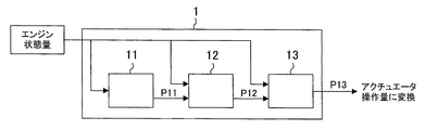
- FIG. 1 is a block diagram showing a model structure of the present embodiment.
- the model 1 used in the present embodiment has a structure in which a plurality of submodels 11, 12, and 13 are hierarchically connected.
- the sub model 11 is at the top of the hierarchical order, and the sub model 13 is at the bottom.
- a parameter (parameter P13 shown in FIG. 1) calculated by the lowest submodel 13 is a parameter finally output from the model 1.
- the present control device uses this parameter P13 for calculating the actuator operation amount.
- the model 1 is input with various engine state quantities acquired by the sensor.
- the input engine state quantity is used for calculation of parameters in each sub model.
- Each submodel itself models the function and characteristics of the engine, and the parameters calculated in each submodel are parameters related to the engine control amount.
- the calculated parameters are different for each submodel. Specifically, the parameters calculated in the upper submodel and the parameters calculated in the lower submodel of the two consecutive submodels in the order are in a relationship between the target and the means.
- the parameter P11 calculated by the uppermost submodel 11 is the target of the parameter P12 calculated by the lower submodel 12.
- the means for achieving the parameter P11 is the parameter P12.
- the value of the parameter P13 for achieving the target value is calculated from various engine state quantities using the value of the parameter P13 as the target value.
- the value of the parameter P12 for achieving the target value is calculated from various engine state quantities with the value of the parameter P12 as the target value.
- the value of the parameter P11 is calculated only from the engine state quantity.
- the parameter P11 calculated by the uppermost submodel 11 is a final target, and the requirements regarding engine performance such as drivability, exhaust gas performance, and fuel consumption rate are reflected in the value of the parameter P11. That is, the parameter P11 calculated by the highest submodel 11 is a numerical value of the engine performance requirement.
- the parameter values can be calculated even when the direct upper submodel is not used. That is, the lower submodels 12 and 13 are constructed so that the values of the respective parameters can be calculated only from the engine state quantity, similarly to the uppermost submodel 11. For example, in the sub model 13, when the sub model 12 is used, an optimal solution for achieving the parameter P 12 as a target value is calculated as the value of the parameter P 13. On the other hand, when the submodel 12 is not used, one preferred solution predicted from the engine state quantity is calculated as the value of the parameter P13.
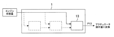
- the model 1 used in the present control device has a variable model structure. That is, as shown in FIG. 1, not only calculations using all submodels but also calculations using only some submodels as shown in FIG. 2 or FIG. 3 are possible.
- the value of the parameter P11 is calculated from the engine state quantity in the uppermost submodel 11.
- the value of the parameter P12 is calculated from the engine state quantity with the value of the parameter P11 as a target value.
- the value of the parameter P13 is calculated from the engine state quantity with the value of the parameter P12 as a target value.
- the submodel 12 and the submodel 13 are used in the model 1.
- the value of the parameter P12 is calculated from the engine state quantity in the submodel 12.
- the value of the parameter P13 is calculated from the engine state quantity using the value of the parameter P12 as a target value.
- the balance between the accuracy of the model 1 and the calculation load can be arbitrarily adjusted according to the number of upper submodels used in combination with the lowest submodel 13. Can do.
- the present control device selects such a combination according to the engine operating status, for example, the engine speed. This is because when the calculation using the model 1 is performed at every constant crank angle, the load applied to the calculation increases as the engine speed increases.
- the model structure shown in FIG. 1 is adopted in the low rotation region
- the model structure shown in FIG. 2 is adopted in the middle rotation region
- the model structure shown in FIG. 3 is adopted in the high rotation region.
- model of the present embodiment has three layers, but a model having a larger number of layers can also be used. A model with higher accuracy can be constructed by increasing the number of hierarchies. Conversely, a model with only the upper and lower two layers is also allowed.
- one submodel is set in one layer, but a plurality of submodels can be set in one layer.
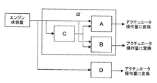
- FIG. 4 is a diagram showing an application example when the model structure shown in FIG. 1 is a basic structure.
- two models are operated in parallel.
- One model is a hierarchical model ⁇ composed of an upper submodel C and lower submodels A and B.
- Another model is a model D having no hierarchical structure. The parameters calculated in the sub-models A and B at the lowest level of the model ⁇ and the parameters calculated in the model D are converted into different actuator operation amounts.
- the most preferable combination is a combination that does not exceed the calculation capability of the control device and can use the calculation capability to the limit.
- the combination varies depending on the engine operating conditions, particularly the engine speed.
- the present control device sets a load index value serving as an index of calculation load for each model (submodel) and for each engine speed, and stores the setting in a memory.
- the hierarchy of the upper submodel used in combination with the lowest submodel is raised to a higher level within a range where the integrated value of the load index value does not exceed the reference value. .
- the load index value at each engine speed is set as follows. Number of revolutions (rpm) Load index value Sub model A [1000 2000 3000] [10 20 30] Sub model B [1000 2000 3000] [10 20 30] Sub model C [1000 2000 3000] [40 40 50] Model D [1000 2000 3000] [30 35 40]
- the reference value (allowable maximum value) of the integrated value of the load index value is 100.
- the submodels A and B can be used in combination with the submodel C. That is, the calculation by the submodels A, B, and C can be performed in parallel with the calculation by the model D.
- the engine speed is 2000 rpm or 3000 rpm
- there is no allowance for computing capacity so in model ⁇ , submodel C cannot be combined with submodels A and B. Therefore, in parallel with the calculation by the model D, the calculation by the sub models A and B is performed in the model ⁇ .
- the model structure used for the calculation based on the load index value it is possible to always utilize the calculation capability of the control device to the limit.
- FIG. 5 is a diagram showing another application example when the model structure shown in FIG. 1 is used as a basic structure.
- the first model is a hierarchical model ⁇ composed of an upper submodel C and lower submodels A and B.
- the second model is a model D having no hierarchical structure.
- the third model is a hierarchical model ⁇ composed of an upper submodel G and lower submodels E and F.
- the parameters calculated in the lowest submodels A and B of the model ⁇ , the parameters calculated in the model D, and the parameters calculated in the lowest submodels E and F of the model ⁇ are different from each other. Converted to actuator operation amount.
- various combinations of models can be selected within a range in which the integrated value of the load index value does not exceed the reference value.
- a priority order may be given between models having a hierarchical structure, and a higher-order submodel may be combined with a lower-order submodel preferentially from a model with a higher priority order. For example, if the priority order of the model ⁇ is 1st and the priority order of the model ⁇ is 2nd, the upper submodel C is first combined with the lowest submodels A and B in the model ⁇ .
- the upper submodel G is combined with the lowest submodels E and F in the model ⁇ . According to this, since the calculation capability of the control device is preferentially assigned to the calculation of a model having a high priority, the calculation capability of the control device can be effectively used.
- the priority order between models having a hierarchical structure can be made variable according to the operating state of the engine. For example, it is possible to increase the priority of the model ⁇ in a situation where the exhaust gas performance is prioritized, and to increase the priority of the model ⁇ in a situation where the fuel efficiency is prioritized. By doing so, the calculation capability of the control device is assigned to the calculation of the model with the highest priority in the present situation, so that the calculation capability of the control device can be used more effectively.
- FIG. 6 is a diagram showing a model structure of the present embodiment.
- the control element of the present control device has a model group including a plurality of models 2, 4, and 6 having different scales.
- Various engine state quantities acquired by the sensors are input to the models 2, 4, and 6.
- the input engine state quantity is used to calculate parameters in the models 2, 4, and 6.
- the parameters calculated in each model are the same, and any parameter is used for calculating the same actuator operation amount.
- the difference in the scale of each model 2, 4 and 6 represents the difference in accuracy.
- the largest model 2 has the highest accuracy.
- the calculation load of the control device is the largest.
- the model 6 of the minimum scale has the lowest calculation load on the control device, although the accuracy is reduced.
- the model of the present embodiment is configured such that a large scale model includes a small scale model. Specifically, the larger model of two consecutive models in the hierarchy is composed of a lower submodel corresponding to the smaller model and an upper submodel combined with the lower submodel. .
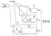
- FIG. 7 is an expanded view of the model structure shown in FIG.
- the maximum scale model 2 has a configuration in which a lower submodel 22 and an upper submodel 21 corresponding to the medium scale model 4 are combined.
- the engine state quantity input to the model 2 is used for parameter calculation in each sub model.
- the parameter P21 calculated by the upper submodel 21 and the parameter P2 calculated by the lower submodel 22 have a relationship between the target and the means.
- the upper submodel 21 is constructed so as to calculate the value of the parameter P21 from the engine state quantity. Requirements relating to engine performance such as drivability, exhaust gas performance, and fuel consumption rate are reflected in the value of this parameter P21.
- the parameter P21 calculated by the upper submodel 21 is a numerical value of the engine performance requirement.
- the lower submodel 22 is constructed so as to calculate the value of the parameter P2 for achieving the target value from the engine state quantity using the value of the parameter P21 calculated by the upper submodel 21 as the target value.
- the medium-scale model 4 has a configuration in which a lower submodel 42 and an upper submodel 41 corresponding to the smallest model 6 are combined.
- the engine state quantity input to the model 4 is used for parameter calculation in each sub model.
- the parameter P41 calculated by the upper submodel 41 and the parameter P4 calculated by the lower submodel 42 have a relationship between the target and the means.
- the upper submodel 41 is constructed so as to calculate the value of the parameter P41 from the engine state quantity.
- the lower submodel 42 is constructed so as to calculate the value of the parameter P4 for achieving the target value from the engine state quantity using the value of the parameter P41 calculated by the upper submodel 41 as the target value.
- the minimum scale model 6 is constructed so as to calculate the value of the parameter P6 only from the engine state quantity.
- the parameters P2, P4, and P6 calculated by the models 2, 4, and 6 are the same parameters that are used for calculating the same actuator operation amount. However, the values do not necessarily match.
- the parameter P2 calculated by the model 2 is determined with the parameter P21 obtained by quantifying the requirements relating to engine performance as the target, and therefore has the highest accuracy in terms of achieving the requirements relating to engine performance.
- the calculation load of the control device increases.
- the parameter P4 calculated by the model 4 is determined with the parameter P41 as a target.
- the parameter P41 is not an optimal solution for achieving the parameter P21, but is one suitable predicted from the engine state quantity. It is a solution.
- the parameter P4 is less accurate than the parameter P2 in terms of achieving the requirements regarding engine performance, but the calculation load of the control device is reduced. Since the parameter P6 calculated by the model 6 is one preferable solution predicted from only the engine state quantity, the parameter P6 is lower than the other parameters P2 and P4 in terms of the accuracy of achievement of the requirements related to engine performance. . However, the calculation load on the control device can be minimized.
- the balance between the accuracy of the model and the calculation load can be arbitrarily adjusted according to the scale of the model selected from the model group.
- the present control device performs such model selection in accordance with the operating state of the engine, for example, the engine speed. This is because when the calculation using the model is performed at every constant crank angle, the load applied to the calculation increases as the engine speed increases.
- the model 2 is selected in the low rotation range
- the model 4 is selected in the middle rotation range
- the model 6 is selected in the high rotation range.
- model group of this Embodiment contains three models, it can also contain many models from which a scale differs. A model with higher accuracy can be constructed by increasing the scale of the model. Conversely, a model group composed of two models having different scales is also allowed. Moreover, although the model group of this Embodiment differs in scale in all the models, it is also possible to include a plurality of models of the same scale.
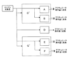
- FIG. 8 is a diagram showing an application example when the model structure shown in FIGS. 6 and 7 is a basic structure.
- a model group including models A, B, and C ′ is used.
- Model A and model B are models of the same scale, and calculate parameters used for calculating different actuator operation amounts.
- the model C ′ is a model having a larger scale including the model A and the model B, and the above-described parameters can be calculated with higher accuracy than the models A and B.
- one of the calculations based on the models A and B and the calculation based on the model C ′ is selected.
- the model D is a model independent of the model group, and the calculation is performed in parallel with the model selected from the model group.
- the model selection method will be examined using the model structure shown in FIG. 8 as an example.
- the most preferable combination is a combination that does not exceed the calculation capability of the control device and can use the calculation capability to the limit.
- the combination varies depending on the engine operating conditions, particularly the engine speed.
- the present control device sets a load index value, which is an index of the calculation load, for each model and for each engine speed, and stores the setting in a memory.
- the scale of the model to be selected is increased within a range where the integrated value of the load index value does not exceed the reference value.
- the load index value at each engine speed is set as follows. Speed (rpm) Load index value Model A [1000 2000 3000] [10 20 30] Model B [1000 2000 3000] [10 20 30] Model C '[1000 2000 3000] [60 80 100] Model D [1000 2000 3000] [30 35 40]
- the reference value (allowable maximum value) of the integrated value of the load index value is 100.
- the model C ′ can be selected from the model group. That is, the calculation by the model C ′ can be performed in parallel with the calculation by the model D.
- the model C ′ cannot be selected from the model group.
- the models A and B are selected from the model group, and the calculations by the models A and B are performed in parallel with the calculation by the model D.
- the selection of the model to be used for calculation is determined based on the load index value, so that the calculation capability of the control device can always be utilized to the limit.
- FIG. 9 is a diagram showing another application example when the model structure shown in FIGS. 6 and 7 is used as a basic structure.
- two model groups are prepared.
- the model G ′ is a larger model including the models E and F, and can calculate parameters with higher accuracy than the models E and F.
- priorities are given in advance between two model groups, and the models used for calculating the actuator operation amount in order from the model group with the highest priority within a range where the load index value does not exceed the reference value. Enlarging the scale of is done. By doing so, the calculation capability of the control device is preferentially assigned to the calculation of the model group having a high priority, so that the calculation capability of the control device can be effectively utilized.
- the priority order between the model groups can be made variable according to the operating state of the engine. For example, in a situation where exhaust gas performance is prioritized, priority is given to the model group consisting of models A, B, and C ′, and in a situation where fuel efficiency is prioritized, priority is given to the model group consisting of models E, F, and G ′. It is also possible to increase the ranking. By doing so, the calculation capability of the control device is assigned to the calculation of the model group having the highest priority at present, so that the calculation capability of the control device can be used more effectively.
- FIG. 10 is a diagram showing a modification of the model structure shown in FIG.
- calculation using the model C ′ and the model B is possible. That is, one parameter is calculated by a small model B among two parameters for calculating the amount of actuator operation handled by the model group including models A, B, and C ′, while the other parameter is a large scale.
- the model C ′ is used for calculation.
- one parameter may be calculated with the model C ′, and the other parameter may be calculated with the small model A.
- the calculation capability of the control device can be more effectively utilized by calculating with the large-scale model C ′ with priority given to parameters that require higher accuracy.
Abstract
Description
本発明の実施の形態1について図を参照して説明する。
回転数(rpm) 負荷指標値
サブモデルA [1000 2000 3000] [10 20 30]
サブモデルB [1000 2000 3000] [10 20 30]
サブモデルC [1000 2000 3000] [40 40 50]
モデルD [1000 2000 3000] [30 35 40] For example, it is assumed that the load index value at each engine speed is set as follows.
Number of revolutions (rpm) Load index value Sub model A [1000 2000 3000] [10 20 30]
Sub model B [1000 2000 3000] [10 20 30]
Sub model C [1000 2000 3000] [40 40 50]
Model D [1000 2000 3000] [30 35 40]
次に、本発明の実施の形態2について図を参照して説明する。
Next, a second embodiment of the present invention will be described with reference to the drawings.
回転数(rpm) 負荷指標値
モデルA [1000 2000 3000] [10 20 30]
モデルB [1000 2000 3000] [10 20 30]
モデルC′ [1000 2000 3000] [60 80 100]
モデルD [1000 2000 3000] [30 35 40] For example, it is assumed that the load index value at each engine speed is set as follows.
Speed (rpm) Load index value Model A [1000 2000 3000] [10 20 30]
Model B [1000 2000 3000] [10 20 30]
Model C '[1000 2000 3000] [60 80 100]
Model D [1000 2000 3000] [30 35 40]
以上、本発明の実施の形態について説明したが、本発明は上述の実施の形態に限定されるものではなく、本発明の趣旨を逸脱しない範囲で種々変形して実施することができる。 Others.
Although the embodiments of the present invention have been described above, the present invention is not limited to the above-described embodiments, and various modifications can be made without departing from the spirit of the present invention.
11 サブモデル(最上位)
12 サブモデル(中間)
13 サブモデル(最下位)
2 モデル(大規模)
4 モデル(中規模)
6 モデル(小規模)
21,41 上位サブモデル
22,42 下位サブモデル 1 Model 11 Sub model (top)
12 Submodel (intermediate)
13 Submodel (lowest)
2 models (large scale)
4 models (medium scale)
6 models (small scale)
21, 41
Claims (8)
- 1又は複数のアクチュエータを操作して内燃機関の運転を制御する制御装置において、
前記内燃機関の状態を示す複数種の状態量(以下、エンジン状態量)を取得するための複数種のセンサと、
前記エンジン状態量からアクチュエータ操作量を演算する演算要素であって、その演算過程においてモデルを使用する演算要素と、を備え、
前記モデルは、階層的序列を有する複数のサブモデルからなり、
序列において連続する2つのサブモデルのうち上位のサブモデルで計算されるパラメータと、下位のサブモデルで計算されるパラメータとは目標と手段との関係にあり、
最上位サブモデルは、前記内燃機関の性能に関する要求が数値化されたパラメータを計算するサブモデルであって、前記エンジン状態量を用いてパラメータの値を計算するように構築され、
最上位以外の各サブモデルは、直接の上位のサブモデルが使用されている場合には、当該上位モデルで算出されたパラメータの値を目標値として前記エンジン状態量から当該目標値を達成するためのパラメータの値を算出し、直接の上位のサブモデルが使用されていない場合には、前記エンジン状態量のみからパラメータの値を算出するように構築され、
前記演算要素は、最下位サブモデルで算出されたパラメータの値を用いて前記アクチュエータ操作量を演算し、前記内燃機関の運転状況に応じて前記最下位サブモデルと組み合わせて使用する上位サブモデルの個数を変更することを特徴とする内燃機関の制御装置。 In a control device that controls operation of an internal combustion engine by operating one or more actuators,
A plurality of types of sensors for acquiring a plurality of types of state quantities (hereinafter referred to as engine state quantities) indicating the state of the internal combustion engine;
A calculation element for calculating an actuator operation amount from the engine state quantity, the calculation element using a model in the calculation process,
The model is composed of a plurality of submodels having a hierarchical order,
The parameters calculated in the upper submodel and the parameters calculated in the lower submodel of the two consecutive submodels in the order are in a relationship between the target and the means.
The highest-level submodel is a submodel that calculates a parameter in which requirements regarding the performance of the internal combustion engine are quantified, and is constructed so as to calculate a value of the parameter using the engine state quantity,
In order to achieve the target value from the engine state quantity with the value of the parameter calculated by the higher-order model as the target value when each of the sub-models other than the highest is used as a direct higher-order submodel If the direct upper sub-model is not used, it is constructed to calculate the parameter value only from the engine state quantity,
The calculation element calculates the actuator operation amount using the parameter value calculated in the lowest submodel, and the upper submodel used in combination with the lowest submodel according to the operating state of the internal combustion engine. A control device for an internal combustion engine, wherein the number is changed. - 前記演算要素は、演算負荷の指標となる数値(以下、負荷指標値)をサブモデルごとに、且つ、前記内燃機関の運転状況ごとに記憶していて、負荷指標値の積算値が基準値を超えない範囲内で、前記最下位サブモデルと組み合わせて使用する上位サブモデルの階層をより上位に上げていくことを特徴とする請求項1記載の内燃機関の制御装置。 The calculation element stores a numerical value (hereinafter referred to as a load index value) serving as an index of calculation load for each sub model and for each operating state of the internal combustion engine, and the integrated value of the load index value is a reference value. 2. The control device for an internal combustion engine according to claim 1, wherein a hierarchy of the upper submodel used in combination with the lowest submodel is raised to a higher level within a range not exceeding.
- 前記演算要素は、異なるアクチュエータ操作量をそれぞれ演算するために構造の異なる複数のモデルを有し、
前記複数のモデル間には優先順位が付けられていて、
前記演算要素は、負荷指標値の積算値が基準値を超えない範囲内で、優先順位の高いモデルから順に、最下位サブモデルと組み合わせて使用する上位サブモデルの階層をより上位に上げていくことを特徴とする請求項2記載の内燃機関の制御装置。 The calculation element has a plurality of models with different structures in order to calculate different actuator operation amounts,
Priorities are assigned between the plurality of models,
The calculation element raises the hierarchy of the upper submodel used in combination with the lowest submodel in order from the model with the highest priority within the range where the integrated value of the load index value does not exceed the reference value. The internal combustion engine control apparatus according to claim 2. - 前記演算要素は、前記内燃機関の運転状況に応じて、前記複数のモデル間の優先順位を変更することを特徴とする請求項3記載の内燃機関の制御装置。 The control device for an internal combustion engine according to claim 3, wherein the calculation element changes a priority order among the plurality of models in accordance with an operation state of the internal combustion engine.
- 1又は複数のアクチュエータを操作して内燃機関の運転を制御する制御装置において、
前記内燃機関の状態を示す複数種の状態量(以下、エンジン状態量)を取得するための複数種のセンサと、
前記エンジン状態量からアクチュエータ操作量を演算する演算要素であって、その演算過程においてモデルを使用する演算要素と、を備え、
前記演算要素は、同一のアクチュエータ操作量の演算のために規模の異なる複数のモデルからなるモデル群を有し、
前記複数のモデルの間には規模順に序列が付けられ、
序列において連続する2つのモデルのうち規模の大きい方のモデルは、規模の小さい方のモデルに相当する下位サブモデルと、前記下位サブモデルに結合された上位サブモデルとからなり、前記下位サブモデルは、前記上位サブモデルで算出されたパラメータの値を目標値として前記エンジン状態量から当該目標値を達成するためのパラメータの値を算出するように構築され、
前記演算要素は、前記アクチュエータ操作量の演算に使用するモデルを前記モデル群の中から前記内燃機関の運転状況に応じて選択し、選択したモデルで算出されたパラメータの値を用いて前記アクチュエータ操作量を演算することを特徴とする内燃機関の制御装置。 In a control device that controls operation of an internal combustion engine by operating one or more actuators,
A plurality of types of sensors for acquiring a plurality of types of state quantities (hereinafter referred to as engine state quantities) indicating the state of the internal combustion engine;
A calculation element for calculating an actuator operation amount from the engine state quantity, the calculation element using a model in the calculation process,
The calculation element has a model group consisting of a plurality of models of different scales for calculating the same actuator operation amount,
The multiple models are ranked in order of size,
Of the two models that are consecutive in the order, the larger model includes a lower submodel corresponding to the smaller model and an upper submodel coupled to the lower submodel, and the lower submodel. Is constructed so as to calculate the value of the parameter for achieving the target value from the engine state quantity with the value of the parameter calculated in the upper submodel as a target value,
The calculation element selects a model to be used for calculation of the actuator operation amount from the model group according to an operation state of the internal combustion engine, and uses the parameter value calculated by the selected model to operate the actuator A control device for an internal combustion engine, characterized by calculating an amount. - 前記演算要素は、演算負荷の指標となる数値(以下、負荷指標値)をモデルごとに、且つ、前記内燃機関の運転状況ごとに記憶していて、負荷指標値が基準値を超えない範囲内で最大となるモデルを前記モデル群の中から選択することを特徴とする請求項5記載の内燃機関の制御装置。 The calculation element stores a numerical value (hereinafter referred to as a load index value) serving as an index of calculation load for each model and for each operating state of the internal combustion engine, and the load index value is within a range not exceeding a reference value. 6. The control apparatus for an internal combustion engine according to claim 5, wherein a model having the maximum value is selected from the model group.
- 前記演算要素は、異なるアクチュエータ操作量をそれぞれ演算するために複数のモデル群を有し、
前記複数のモデル群間には優先順位が付けられていて、
前記演算要素は、負荷指標値が基準値を超えない範囲内で、優先順位の高いモデル群から順に、前記アクチュエータ操作量の演算に使用するモデルの規模を大きくしていくことを特徴とする請求項6記載の内燃機関の制御装置。 The calculation element has a plurality of model groups for calculating different actuator operation amounts, respectively.
Priorities are assigned between the plurality of model groups,
The calculation element increases the scale of a model used for calculating the actuator operation amount in order from a model group having a higher priority within a range in which a load index value does not exceed a reference value. Item 7. A control device for an internal combustion engine according to Item 6. - 前記演算要素は、前記内燃機関の運転状況に応じて、前記複数のモデル群間の優先順位を変更することを特徴とする請求項7記載の内燃機関の制御装置。 The control device for an internal combustion engine according to claim 7, wherein the calculation element changes a priority order among the plurality of model groups in accordance with an operation state of the internal combustion engine.
Priority Applications (5)
| Application Number | Priority Date | Filing Date | Title |
|---|---|---|---|
| EP10849181.2A EP2562401B1 (en) | 2010-04-21 | 2010-04-21 | Controller for internal combustion engine |
| JP2011542392A JP5168419B2 (en) | 2010-04-21 | 2010-04-21 | Control device for internal combustion engine |
| PCT/JP2010/057077 WO2011132277A1 (en) | 2010-04-21 | 2010-04-21 | Controller for internal combustion engine |
| US13/257,871 US8478507B2 (en) | 2010-04-21 | 2010-04-21 | Control device for internal combustion engine |
| CN201080041815.4A CN102985673B (en) | 2010-04-21 | 2010-04-21 | Controller for internal combustion engine |
Applications Claiming Priority (1)
| Application Number | Priority Date | Filing Date | Title |
|---|---|---|---|
| PCT/JP2010/057077 WO2011132277A1 (en) | 2010-04-21 | 2010-04-21 | Controller for internal combustion engine |
Publications (1)
| Publication Number | Publication Date |
|---|---|
| WO2011132277A1 true WO2011132277A1 (en) | 2011-10-27 |
Family
ID=44833835
Family Applications (1)
| Application Number | Title | Priority Date | Filing Date |
|---|---|---|---|
| PCT/JP2010/057077 WO2011132277A1 (en) | 2010-04-21 | 2010-04-21 | Controller for internal combustion engine |
Country Status (5)
| Country | Link |
|---|---|
| US (1) | US8478507B2 (en) |
| EP (1) | EP2562401B1 (en) |
| JP (1) | JP5168419B2 (en) |
| CN (1) | CN102985673B (en) |
| WO (1) | WO2011132277A1 (en) |
Families Citing this family (21)
| Publication number | Priority date | Publication date | Assignee | Title |
|---|---|---|---|---|
| WO2011142038A1 (en) * | 2010-05-10 | 2011-11-17 | トヨタ自動車株式会社 | Control device of internal combustion engine |
| JP5932128B2 (en) * | 2013-02-21 | 2016-06-08 | トヨタ自動車株式会社 | Control device design method and control device |
| WO2017065754A1 (en) | 2015-10-14 | 2017-04-20 | Cummins Inc. | Reference value engine control systems and methods |
| WO2017065756A1 (en) | 2015-10-14 | 2017-04-20 | Cummins Inc. | Hierarchical engine control systems and methods |
| WO2017065753A1 (en) | 2015-10-14 | 2017-04-20 | Cummins Inc. | Reference value engine control systems and methods |
| EP3362663A4 (en) | 2015-10-14 | 2019-06-26 | Cummins, Inc. | Reference value engine control systems and methods |
| US11437032B2 (en) | 2017-09-29 | 2022-09-06 | Shanghai Cambricon Information Technology Co., Ltd | Image processing apparatus and method |
| US11630666B2 (en) | 2018-02-13 | 2023-04-18 | Shanghai Cambricon Information Technology Co., Ltd | Computing device and method |
| US11397579B2 (en) | 2018-02-13 | 2022-07-26 | Shanghai Cambricon Information Technology Co., Ltd | Computing device and method |
| EP3651078B1 (en) | 2018-02-13 | 2021-10-27 | Shanghai Cambricon Information Technology Co., Ltd | Computation device and method |
| CN116991225A (en) * | 2018-02-14 | 2023-11-03 | 上海寒武纪信息科技有限公司 | Control device, method and equipment of processor |
| EP3624020A4 (en) | 2018-05-18 | 2021-05-05 | Shanghai Cambricon Information Technology Co., Ltd | Computing method and related product |
| KR102470893B1 (en) | 2018-06-27 | 2022-11-25 | 상하이 캠브리콘 인포메이션 테크놀로지 컴퍼니 리미티드 | Debug method by breakpoint of on-chip code, chip debug system by on-chip processor and breakpoint |
| KR102519467B1 (en) | 2018-08-28 | 2023-04-06 | 캠브리콘 테크놀로지스 코퍼레이션 리미티드 | Data pre-processing method, device, computer equipment and storage medium |
| WO2020062392A1 (en) | 2018-09-28 | 2020-04-02 | 上海寒武纪信息科技有限公司 | Signal processing device, signal processing method and related product |
| CN111383637A (en) | 2018-12-28 | 2020-07-07 | 上海寒武纪信息科技有限公司 | Signal processing device, signal processing method and related product |
| CN111832737B (en) | 2019-04-18 | 2024-01-09 | 中科寒武纪科技股份有限公司 | Data processing method and related product |
| US11847554B2 (en) | 2019-04-18 | 2023-12-19 | Cambricon Technologies Corporation Limited | Data processing method and related products |
| US11676028B2 (en) | 2019-06-12 | 2023-06-13 | Shanghai Cambricon Information Technology Co., Ltd | Neural network quantization parameter determination method and related products |
| CN112085185B (en) | 2019-06-12 | 2024-04-02 | 上海寒武纪信息科技有限公司 | Quantization parameter adjustment method and device and related product |
| JP7097420B2 (en) * | 2020-10-29 | 2022-07-07 | 株式会社ジャパンエンジンコーポレーション | Main engine control system |
Citations (5)
| Publication number | Priority date | Publication date | Assignee | Title |
|---|---|---|---|---|
| JP2007293707A (en) * | 2006-04-26 | 2007-11-08 | Toyota Motor Corp | System model formation support apparatus and method |
| JP2008133767A (en) * | 2006-11-28 | 2008-06-12 | Toyota Motor Corp | Model simplification method in model base development |
| JP2008144680A (en) * | 2006-12-11 | 2008-06-26 | Toyota Motor Corp | Air quantity estimation device for internal combustion engine |
| JP2009047102A (en) | 2007-08-21 | 2009-03-05 | Toyota Motor Corp | Control device for vehicle driving unit |
| JP2009299509A (en) * | 2008-06-10 | 2009-12-24 | Honda Motor Co Ltd | Fuel supply control device |
Family Cites Families (15)
| Publication number | Priority date | Publication date | Assignee | Title |
|---|---|---|---|---|
| US4974563A (en) * | 1988-05-23 | 1990-12-04 | Toyota Jidosha Kabushiki Kaisha | Apparatus for estimating intake air amount |
| JP2539540B2 (en) * | 1990-09-19 | 1996-10-02 | 株式会社日立製作所 | Process control equipment |
| US5794171A (en) * | 1996-02-29 | 1998-08-11 | Ford Global Technologies, Inc. | Process for deriving predictive model of crankshaft rotation of a combustion engine |
| US6278986B1 (en) * | 1996-06-27 | 2001-08-21 | Yahama Hatsudoki Kabushiki Kaisha | Integrated controlling system |
| US6021369A (en) * | 1996-06-27 | 2000-02-01 | Yamaha Hatsudoki Kabushiki Kaisha | Integrated controlling system |
| DE19744230B4 (en) * | 1997-10-07 | 2007-10-25 | Robert Bosch Gmbh | Control units for a system and method for operating a control unit |
| US6415272B1 (en) * | 1998-10-22 | 2002-07-02 | Yamaha Hatsudoki Kabushiki Kaisha | System for intelligent control based on soft computing |
| US6336070B1 (en) * | 2000-03-01 | 2002-01-01 | Ford Global Technologies, Inc. | Apparatus and method for engine crankshaft torque ripple control in a hybrid electric vehicle |
| JP4205030B2 (en) | 2003-10-06 | 2009-01-07 | 本田技研工業株式会社 | Air-fuel ratio control device for internal combustion engine |
| ITTO20030999A1 (en) * | 2003-12-12 | 2005-06-13 | Fiat Ricerche | METHOD OF ACTIVATION OF THE REGENERATION OF A PARTICULATE FILTER ACCORDING TO AN ESTIMATE OF THE QUANTITY OF THE PARTICULATE ACCUMULATED IN THE FILTER OF THE PARTICULATE. |
| JP4155198B2 (en) | 2004-01-19 | 2008-09-24 | トヨタ自動車株式会社 | Abnormality detection device for vehicle control system |
| DE102005058081B9 (en) * | 2005-12-06 | 2009-01-29 | Airbus Deutschland Gmbh | Method for the reconstruction of gusts and structural loads in aircraft, in particular commercial aircraft |
| JP4209435B2 (en) * | 2006-10-19 | 2009-01-14 | 本田技研工業株式会社 | Control device |
| JP4321656B2 (en) * | 2007-04-27 | 2009-08-26 | トヨタ自動車株式会社 | Vehicle control device |
| JP5006947B2 (en) * | 2010-01-14 | 2012-08-22 | 本田技研工業株式会社 | Plant control equipment |
-
2010
- 2010-04-21 US US13/257,871 patent/US8478507B2/en not_active Expired - Fee Related
- 2010-04-21 JP JP2011542392A patent/JP5168419B2/en not_active Expired - Fee Related
- 2010-04-21 CN CN201080041815.4A patent/CN102985673B/en not_active Expired - Fee Related
- 2010-04-21 WO PCT/JP2010/057077 patent/WO2011132277A1/en active Application Filing
- 2010-04-21 EP EP10849181.2A patent/EP2562401B1/en not_active Not-in-force
Patent Citations (5)
| Publication number | Priority date | Publication date | Assignee | Title |
|---|---|---|---|---|
| JP2007293707A (en) * | 2006-04-26 | 2007-11-08 | Toyota Motor Corp | System model formation support apparatus and method |
| JP2008133767A (en) * | 2006-11-28 | 2008-06-12 | Toyota Motor Corp | Model simplification method in model base development |
| JP2008144680A (en) * | 2006-12-11 | 2008-06-26 | Toyota Motor Corp | Air quantity estimation device for internal combustion engine |
| JP2009047102A (en) | 2007-08-21 | 2009-03-05 | Toyota Motor Corp | Control device for vehicle driving unit |
| JP2009299509A (en) * | 2008-06-10 | 2009-12-24 | Honda Motor Co Ltd | Fuel supply control device |
Non-Patent Citations (1)
| Title |
|---|
| See also references of EP2562401A4 |
Also Published As
| Publication number | Publication date |
|---|---|
| US20130054110A1 (en) | 2013-02-28 |
| US8478507B2 (en) | 2013-07-02 |
| JP5168419B2 (en) | 2013-03-21 |
| CN102985673B (en) | 2015-06-17 |
| EP2562401B1 (en) | 2016-12-28 |
| EP2562401A4 (en) | 2013-09-11 |
| JPWO2011132277A1 (en) | 2013-07-18 |
| CN102985673A (en) | 2013-03-20 |
| EP2562401A1 (en) | 2013-02-27 |
Similar Documents
| Publication | Publication Date | Title |
|---|---|---|
| JP5168419B2 (en) | Control device for internal combustion engine | |
| US7177758B2 (en) | Method for optimizing characteristics map | |
| US6092017A (en) | Parameter estimation apparatus | |
| US6363907B1 (en) | Air induction control system for variable displacement internal combustion engine | |
| KR101125489B1 (en) | Controller for internal-combustion engine | |
| US20100211287A1 (en) | Internal combustion engine control device | |
| US7853394B2 (en) | Internal combustion engine feedback control with variably set gain | |
| JP2019135393A (en) | Control device for internal combustion engine and device for outputting output value | |
| CN101435369A (en) | Switching control of RPM-torque | |
| EP0950805A2 (en) | Fuel injection control unit for an engine | |
| JP2004183616A (en) | Controller | |
| JP2004150424A (en) | Controlling device of internal combustion engine | |
| JP5615872B2 (en) | Control device for internal combustion engine | |
| CN110005537B (en) | Control device for internal combustion engine | |
| El Hadef et al. | Neural model for real-time engine volumetric efficiency estimation | |
| JP4180608B2 (en) | Internal combustion engine control device | |
| JP2010190196A (en) | Control device for vehicle driving unit | |
| JP5344049B2 (en) | Control device for internal combustion engine | |
| JP2005105822A (en) | Combustion state estimating device of internal combustion engine | |
| KR102270683B1 (en) | Engine ignition timing efficiency determination method | |
| JP4702085B2 (en) | Combustion state estimation device for internal combustion engine | |
| JPH11294230A (en) | Fuel injection control device for engine | |
| Katrašnik et al. | Tailored cylinder models for system level engine modelling | |
| JP2019127100A (en) | On-vehicle software juxtaposing method and on-vehicle software juxtaposing system | |
| BRPI0306681B1 (en) | fuel injection controller |
Legal Events
| Date | Code | Title | Description |
|---|---|---|---|
| WWE | Wipo information: entry into national phase |
Ref document number: 201080041815.4 Country of ref document: CN |
|
| WWE | Wipo information: entry into national phase |
Ref document number: 13257871 Country of ref document: US |
|
| WWE | Wipo information: entry into national phase |
Ref document number: 2011542392 Country of ref document: JP |
|
| REEP | Request for entry into the european phase |
Ref document number: 2010849181 Country of ref document: EP |
|
| WWE | Wipo information: entry into national phase |
Ref document number: 2010849181 Country of ref document: EP |
|
| 121 | Ep: the epo has been informed by wipo that ep was designated in this application |
Ref document number: 10849181 Country of ref document: EP Kind code of ref document: A1 |
|
| NENP | Non-entry into the national phase |
Ref country code: DE |