WO2011129672A2 - 영상 부호화/복호화 장치 및 방법 - Google Patents
영상 부호화/복호화 장치 및 방법 Download PDFInfo
- Publication number
- WO2011129672A2 WO2011129672A2 PCT/KR2011/002762 KR2011002762W WO2011129672A2 WO 2011129672 A2 WO2011129672 A2 WO 2011129672A2 KR 2011002762 W KR2011002762 W KR 2011002762W WO 2011129672 A2 WO2011129672 A2 WO 2011129672A2
- Authority
- WO
- WIPO (PCT)
- Prior art keywords
- block
- subblock
- prediction
- encoding
- encoded
- Prior art date
- Legal status (The legal status is an assumption and is not a legal conclusion. Google has not performed a legal analysis and makes no representation as to the accuracy of the status listed.)
- Ceased
Links
Images









Classifications
-
- H—ELECTRICITY
- H04—ELECTRIC COMMUNICATION TECHNIQUE
- H04N—PICTORIAL COMMUNICATION, e.g. TELEVISION
- H04N19/00—Methods or arrangements for coding, decoding, compressing or decompressing digital video signals
- H04N19/60—Methods or arrangements for coding, decoding, compressing or decompressing digital video signals using transform coding
- H04N19/61—Methods or arrangements for coding, decoding, compressing or decompressing digital video signals using transform coding in combination with predictive coding
Definitions
- the present invention relates to an image encoding / decoding apparatus and method. More specifically, by dividing the expanded macroblock into subblocks of various sizes and shapes, and encoding the image using different prediction units and transformation units according to the size and shape of the divided subblocks to improve image compression efficiency. A method and apparatus are disclosed. The present invention also relates to an apparatus and method for improving the reconstruction efficiency of an image by receiving a bitstream from such an image encoding apparatus and correspondingly decoding the image.
- Standardized techniques for compressing video data currently include H.261, H.263, H.264, MPEG-2, and MPEG-4.
- each image is encoded by dividing each image into fixed-size macroblocks consisting of a rectangular region of pixels of size 16x16 of luminance and pixels of size 8x8 of chrominance.
- Luma and chrominance components of each macroblock are predicted spatially and temporally, and the predicted residuals are transform and quantization, entropy coding, etc. Compressed through the process of.
- the encoding apparatus can intra-prediction encode by dividing each macroblock into smaller blocks of 16x16, 8x8, and 4x4 sizes, and 4 kinds of 16x16 pixel blocks. Intra prediction encoding is performed using one of prediction modes, and one of nine prediction modes for 8x8 pixel blocks and 4x4 pixel blocks.
- each macroblock may be divided into 16x16 size, 16x8 size, 8x16 size, 8x8 size, 8x4 size, 4x8 size, and 4x4 pixel blocks to be inter prediction encoded. Transform is applied in units of 8x8 size or 4x4 pixel block, and scalar quantization is used as quantization of transform coefficients.
- 16x16 macroblocks are generally suitable for small QCIF and CIF sized images, and are not suitable for macroblocks for high resolution image compression such as 4Kx2K video.
- the conventional video compression technique encodes an image using a fixed size macroblock (although H.264 / AVC divides and encodes a macroblock into smaller block units, the macroblock size is fixed). In the case of encoding a high resolution image, there is a problem that efficient encoding is difficult.
- the present invention extends a macroblock to various sizes, divides the expanded macroblock into subblocks of various sizes and shapes, and different prediction units and transform units according to the size of the divided subblocks.
- the main purpose is to improve the compression efficiency and the reconstruction efficiency by encoding and decoding an image using the image.
- an image encoding / decoding apparatus generates a prediction subblock by predicting a subblock in which a macroblock is divided, and subtracts the residual subblock and the prediction subblock.
- Generate a quantized transform coefficient by transforming and quantizing a residual subblock using a transform selected according to the size of the subblock, generating encoded image data by encoding the quantized transform coefficient, and segmenting the subblock
- An image encoder for selectively calculating and determining an encoding cost when determining an encoding mode for at least one of a block type, a prediction mode, a transform type, and a motion vector for the block; And restoring the partition type information, the motion information, the transform type information, and the quantized transform coefficients by decoding the encoded data having the encoding cost selectively determined, and inverting the quantized transform coefficients by using the transform identified by the recovered transform type information.
- An image encoding apparatus for achieving the above object includes a predictor for predicting a subblock in which a macroblock is divided to generate a predicted subblock; A subtractor for subtracting the subblock and the predictive subblock to generate a residual subblock; A transform and quantizer for transforming and quantizing the remaining subblocks using a transform selected according to the size of the subblock to produce quantized transform coefficients; And an encoder that encodes the quantized transform coefficients to generate encoded image data, wherein the encoding cost is determined when determining an encoding mode for at least one of a block type, a prediction mode, a transform type, and a motion vector for the divided subblock. It is characterized by selectively calculating and determining.
- the encoding cost may be selected and calculated differently depending on whether the size of the subblock is greater than or equal to the size of the set pixel block.
- the coding cost may be calculated according to the following equation.
- RDcost SATD (or SAD) + ⁇ Bit [block type, prediction info, CBP]
- RDcost is a coding cost by a bit rate-distortion optimization technique
- SAD is a sum of absolute values and differences between an original image and a predicted image
- SATD converts residual blocks to absolute values.
- the sum is a sum of the two values
- ⁇ is a constant determined by a quantization parameter
- Bit represents the number of bits required to encode a block to be encoded.
- the coding cost may be calculated according to the following equation.
- RDcost Distortion + ⁇ Bit [block type, prediction info, CBP, coeficient]
- RDcost is an encoding cost by a bit rate-distortion optimization technique
- ⁇ is a constant determined by a quantization parameter
- Bit represents the number of bits necessary for encoding an encoding target block.
- the coding cost may be differently selected depending on whether or not it is used as a reference picture.
- An image decoding apparatus for achieving the above object includes: a decoder configured to decode coded data for which a coding cost is selectively determined and to reconstruct partition type information, motion information, transform type information, and quantized transform coefficients; An inverse quantizer and an inverse transformer for restoring the remaining subblocks by inverse quantization and inverse transformation of the quantized transform coefficients using a transform identified by the transformed type information to be recovered; A predictor for predicting a subblock identified according to the reconstructed partition type information by using the reconstructed motion information to generate a predicted subblock; And an adder for reconstructing the subblock by adding a prediction subblock and the residual subblock.
- an image encoding / decoding method generates a prediction subblock by predicting a subblock in which a macroblock is divided, and subtracts the residual subblock and the prediction subblock.
- a method of encoding an image including: generating a prediction subblock by predicting a subblock in which a macroblock is divided; Generating a residual subblock by subtracting the subblock and the prediction subblock; Transforming and quantizing a residual subblock using a transform selected according to the size of the subblock to generate quantized transform coefficients; And generating encoded image data by encoding the quantized transform coefficients, wherein the encoding cost is determined when determining an encoding mode for at least one of a block type, a prediction mode, a transform type, and a motion vector for the divided subblock. It is characterized by selectively calculating and determining.
- the encoding cost may be selected and calculated differently depending on whether the size of the subblock is greater than or equal to the size of the set pixel block.
- the coding cost may be calculated according to the following equation.
- RDcost SATD (or SAD) + ⁇ Bit [block type, prediction info, CBP]
- RDcost is a coding cost by a bit rate-distortion optimization technique
- SAD is a sum of absolute values and differences between an original image and a predicted image
- SATD converts residual blocks to absolute values.
- the sum is a sum of the two values
- ⁇ is a constant determined by a quantization parameter
- Bit represents the number of bits required to encode a block to be encoded.
- the coding cost may be calculated according to the following equation.
- RDcost Distortion + ⁇ Bit [block type, prediction info, CBP, coeficient]
- RDcost is an encoding cost by a bit rate-distortion optimization technique
- ⁇ is a constant determined by a quantization parameter
- Bit represents the number of bits necessary for encoding an encoding target block.
- the coding cost may be differently selected depending on whether or not it is used as a reference picture.
- An image encoding method for achieving the above object, the method comprising: restoring the partition type information, motion information, transform type information and quantized transform coefficients by decoding the encoded data having the encoding cost selectively determined; Inversely quantizing and inversely transforming the quantized transform coefficients using a transform identified by the transformed type information to be recovered to recover the remaining subblocks; Generating a predicted subblock by predicting a subblock identified according to the reconstructed partition type information using the reconstructed motion information; And reconstructing the subblock by adding the prediction subblock and the residual subblock.
- compression efficiency is achieved by dividing an extended macroblock into subblocks of various sizes and shapes, and encoding and decoding an image using different prediction units and transformation units according to the sizes of the divided subblocks. And the recovery efficiency can be improved.
- FIG. 1 is a block diagram schematically illustrating a video encoding apparatus according to an embodiment of the present invention.
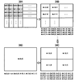
- FIG. 2 is a diagram illustrating encoding and decoding when an input image is padded according to an embodiment of the present invention.
- FIG. 2 illustrates an input image and positions of an extended macroblock to be currently encoded.
- FIG. 3 is an enlarged view of an extended macroblock that is currently encoded in FIG. 2.
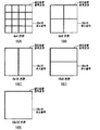
- FIG. 4 is a diagram illustrating an example of a process of dividing a macroblock into subblocks of various sizes for intra prediction encoding and inter prediction encoding according to an embodiment of the present invention.
- FIG. 5 is a diagram illustrating an example of a process of dividing a macroblock into subblocks of various sizes for intra prediction encoding and inter prediction encoding according to another embodiment of the present invention.
- FIG. 6 is an exemplary diagram for describing a method of encoding an intra picture and related data to be transmitted through encoded data, according to an embodiment of the present invention.
- FIG. 7 is an exemplary diagram illustrating nine prediction directions and prediction mode numbers according to intra prediction modes of luminance components according to an embodiment of the present invention.
- FIG. 8 is an exemplary diagram illustrating four prediction directions and prediction mode numbers according to intra prediction modes of luminance components according to an embodiment of the present invention.
- FIG. 9 is an exemplary diagram illustrating three prediction directions and prediction mode numbers according to intra prediction modes of luminance components according to an embodiment of the present invention.
- FIG. 10 is an exemplary diagram illustrating prediction directions and prediction mode numbers according to four intra prediction modes of a color difference component according to an embodiment of the present invention.
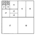
- 11 is an exemplary diagram illustrating various subblock types for an extended macroblock of 64x64 pixels according to an embodiment of the present invention.
- FIG. 12 is an exemplary diagram for describing an encoding method of an inter picture and related data to be transmitted through encoded data according to an embodiment of the present invention.
- FIG. 13 is an exemplary view for explaining a process of determining a predicted motion vector according to an embodiment of the present invention.
- FIG. 14 is an exemplary diagram for describing a process of determining a predicted motion vector of an 8x16 pixel block and a 16x8 pixel block according to an embodiment of the present invention.
- FIG. 15 is an exemplary diagram illustrating types of usable transforms and units in which transform types are encoded according to subblock sizes according to an embodiment of the present invention.
- 16 is an exemplary diagram illustrating a block boundary to perform deblocking filtering according to an embodiment of the present invention.
- 17 is an exemplary diagram illustrating syntax of an intra picture according to an embodiment of the present invention.
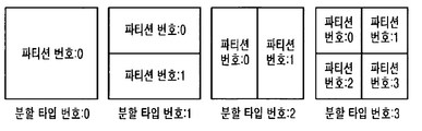
- 18 is an exemplary view showing a number for each division type according to an embodiment of the present invention.
- FIG. 19 is a diagram illustrating a split type number coding sequence in the case of dividing an expanded macroblock into subblocks of various sizes according to an embodiment of the present invention.
- 20 is an exemplary diagram sequentially illustrating a process of dividing a macroblock into divided layers according to an embodiment of the present invention.
- 21 is an exemplary diagram for describing a process of sequentially encoding a split type number for each layer of a macroblock.
- 22 is an exemplary diagram illustrating a coding order of an intra prediction mode according to an embodiment of the present invention.
- FIG. 23 is an exemplary diagram for explaining an example of a process of encoding an intra prediction mode of a macroblock according to an embodiment of the present invention.
- 24 is an exemplary diagram for describing a process of encoding a CBPX_flag and a CBP for an intra macroblock according to an embodiment of the present invention.
- 25 is an exemplary view showing the structure of a CBP according to an embodiment of the present invention.
- FIG. 26 is an exemplary diagram illustrating an example of a sequence of encoding a CBPX flag and a CBP according to an embodiment of the present invention.
- FIG. 27 is an exemplary diagram illustrating another example of a sequence of encoding a CBPX flag and a CBP for an intra macroblock according to an embodiment of the present invention.
- FIG. 28 is an exemplary diagram illustrating a coding order of quantized transform coefficients for each partition type according to an embodiment of the present invention.
- 29 is an exemplary diagram illustrating a syntax structure of encoded data according to an embodiment of the present invention.
- FIG. 30 is a diagram illustrating an example of syntax used in a P-picture (or P-slice) according to an embodiment of the present invention.
- FIG. 31 is a diagram illustrating an example of syntax used in a B-picture (or B-slice) according to an embodiment of the present invention.
- 32 is an exemplary diagram for describing an encoding process of a SKIPX flag according to an embodiment of the present invention.
- 33 and 34 are exemplary diagrams for describing a CBPX_flag, a transform type, and a CBP encoding process for an inter macroblock according to an embodiment of the present invention.
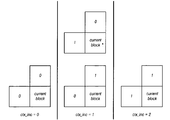
- 35 is a diagram illustrating an example of ctx_inc for encoding / decoding skipX_flag according to an embodiment of the present invention.
- 36 illustrates an example of ctx_inc for encoding / decoding interX_flag according to an embodiment of the present invention.
- 38 and 39 are diagrams for describing a process of encoding split type information using a tree structure according to an embodiment of the present invention.
- FIG. 40 is a diagram illustrating an example of encoding of a partition type according to an embodiment of the present invention.
- 41 is a diagram illustrating another example of split type encoding according to an embodiment of the present invention.
- FIG. 43 is a diagram illustrating an example of ctx_inc for encoding / decoding a transform type when two types of transforms are available according to an embodiment of the present invention.
- FIG. 44 is a diagram illustrating an example of ctx_inc for encoding / decoding a transform type when there are three types of transforms available according to an embodiment of the present invention.
- FIG. 45 is a diagram illustrating another example of ctx_inc for encoding / decoding a transform type when there are three types of transforms available according to an embodiment of the present invention.
- 46 is a block diagram schematically illustrating an image decoding apparatus according to an embodiment of the present invention.
- 48 is a diagram illustrating types of transforms according to an intra prediction mode.
- FIG. 49 is a diagram illustrating types of transforms according to types of horizontal and vertical transforms according to an intra prediction mode of a current block.
- 50 is an exemplary diagram for describing a process of determining a predicted motion vector according to a second embodiment of the present invention.
- 51 is a diagram illustrating an allocation code at the time of encoding the representative motion vector of each block group.
- 52 is a diagram illustrating a current block, neighboring blocks, and the same block.
- 53 is a diagram illustrating an allocation code at the time of encoding motion information of each block.
- 54 is a diagram illustrating a shape of a subblock according to a layer of a block.
- 55 is a diagram illustrating syntax of a macroblock, a subblock, and a predictive subblock of an intra picture according to an embodiment of the present invention.
- 56 is an exemplary diagram illustrating a syntax structure of encoded data for an inter picture according to an embodiment of the present invention.
- 57 is a diagram illustrating an example of a process of encoding transform information and a CBP flag in a macroblock.
- a video encoding apparatus (Video Encoding Apparatus) and a video decoding apparatus (Video Decoding Apparatus) are a personal computer (PC), a notebook computer, a personal digital assistant (PDA).
- a portable multimedia player (PMP: Portable Multimedia Player), a PlayStation Portable (PSP: PlayStation Portable), a wireless communication terminal (Wireless Communication Terminal), a smart phone (smart phone), etc.
- the present invention refers to various devices including a communication device such as a communication modem, a memory for storing various programs and data for encoding or decoding an image, a microprocessor for executing and operating a program, and the like.
- an image encoded in a bitstream by an image encoding apparatus may be connected to a wired / wireless communication network such as the Internet, a local area wireless communication network, a wireless LAN network, a WiBro network, a wireless communication network, a wired telephone network, or the like by using a cable or a general serial bus in real time or in real time.
- the device may be transmitted to an image decoding apparatus through a communication interface such as a universal serial bus (USB), and decoded by the image decoding apparatus to be restored and reproduced as an image.
- a communication interface such as a universal serial bus (USB)
- FIG. 1 is a block diagram schematically illustrating a video encoding apparatus according to an embodiment of the present invention.
- the image encoding apparatus 100 includes a predictor 110, a subtractor 120, a transformer and a quantizer 130, an encoder 140, an inverse quantizer and an inverse transformer 150, and an adder ( 160, a filter 170, and a picture buffer 180.
- the predictor 110 may include an intra predictor 112 and an inter predictor 114, and the inter predictor 114 may further include a motion estimator 116 and a motion compensator 118.
- the input image is input to the image encoding apparatus 100 of FIG. 1 in a frame unit or a field unit, or divided into macroblocks having N ⁇ N pixels (where N is an integer of 16 or more) to be input to the image encoding apparatus 100.
- N is an integer of 16 or more
- encoding may be performed by dividing the macroblock into N macroblocks consisting of integers larger than 16 to improve image compression efficiency.
- a macroblock consisting of integers with N greater than 16 is referred to as an extended macroblock (EMB).
- EMB extended macroblock
- the expanded macroblock may be formed of a square pixel block having a size of 64 ⁇ 64, 32 ⁇ 32, or the like. Note that the macroblock described below is a concept including an extended macroblock and a macroblock of a general 16 ⁇ 16 pixel block.
- N is padded to be a multiple of 16 pixels for the input image when the input image is not a multiple of 16 pixels. Can be performed.
- FIG. 2 is a diagram illustrating image encoding and decoding when an input image is padded according to an embodiment of the present invention.
- FIG. 3 is an enlarged view of an extended macroblock that is an object to be encoded in FIG. . If the location of the input macro padded with multiples of 16 pixels and the extended macroblock to be encoded currently is as shown in FIG. 2, the encoding of the current extended macroblock is a pixel belonging to the padded input image to be a multiple of 16 pixels. It is preferable to use only values. That is, in FIG. 3, the padded region in the current extended macroblock is preferably not used for encoding. It is also preferable to use only pixel values belonging to the input image padded so that the data encoded in the bitstream is a multiple of 16 pixels.
- the macroblock When the input image is an image of 4: 2: 0 format, the macroblock includes a luminance block having N ⁇ N pixels and a color difference block having two pixels.
- the improvement of the compression efficiency of the high resolution image by such an extended macroblock is achieved by the specific embodiment described below.
- the extended macroblock according to an embodiment of the present invention may be internally divided into smaller subblocks as shown in FIG. 4 to perform intra prediction encoding or inter prediction encoding.
- the expanded macroblock may be divided into smaller pixel block units to perform encoding, and each pixel block is divided into smaller subblocks. Encoding can be performed.
- a rectangular shape such as 32 ⁇ 64, 64 ⁇ 32, 16 ⁇ 32, or 32 ⁇ 16, as shown in FIG. It is also possible to omit the division into the pixel blocks, and to divide the expanded macroblock into square pixel blocks and to perform encoding in units of 16 ⁇ 16 pixel blocks.
- the macroblock layer 0 of FIG. 4 includes a 64 ⁇ 64 pixel block, a 64 ⁇ 32 pixel block, a 32 ⁇ 64 pixel block, 32 as a subblock.
- the 32 x 32 pixel block belongs to the macroblock layer 1, and the 32 x 32 pixel block, the 32 x 16 pixel block, the 16 x 32 pixel block, and the 16 x 16 pixel block may belong to the macroblock layer 1.
- subblocks having a rectangular shape such as 64 ⁇ 32 pixel blocks, 32 ⁇ 64 pixel blocks, 32 ⁇ 16 pixel blocks, and 16 ⁇ 32 pixel blocks are divided into subblocks larger than 16 ⁇ 16 pixel blocks. Can be omitted.
- 64x64 pixel blocks and 32x32 pixel blocks, which are subblocks belong to macroblock layer 0
- 32x32 and 16x16 pixel blocks, which are subblocks belong to macroblock layer 1.
- the subblocks of the macroblock layer K + 1 may be used only when the largest subblock of the subblocks of the macroblock layer K (where 0 ⁇ K ⁇ log 2 (N / 4)) is divided into four blocks. have. That is, as shown in FIG.
- the subblocks of macroblock layer 1 may be used only when the 64 ⁇ 64 subblocks of macroblock layer 0 are divided into four subblocks, and the 32 ⁇ 32 subblocks of macroblock layer 1 may be used.
- the subblocks of macroblock layer 2 may be used only when a block is divided into four 16 ⁇ 16 subblocks.
- the image encoding apparatus 100 calculates encoding efficiency for each subblock when the macroblock is divided into subblocks and encoded, and converts the subblock when the highest encoding efficiency is the final intra prediction block or the inter prediction block.
- Decide The coding efficiency may be measured based on a rate-distortion optimization (RDO) technique as shown in Equation (1).
- RDO rate-distortion optimization
- Distortion represents an error value between the encoding target block and the reconstruction block
- ⁇ is a constant determined by a quantization parameter
- Bit represents the number of bits necessary for encoding the encoding target block.
- the encoding cost may be selectively calculated and determined.
- the encoding cost may be selected and calculated differently depending on whether the size of the subblock is equal to or larger than the size of the set pixel block (eg, 16 ⁇ 16 pixel block).
- the mode of a block can be divided into the process of determining the optimal prediction mode (intra prediction mode, motion data) of each block for all types of possible blocks, and then determining the block type, and usually in determining the prediction mode (intra prediction mode).
- SAD Sum of Absolute Difference
- SATD Sum of Absolute Transformed Difference
- Equation 2 SAD refers to the difference between the original image and the predicted image, plus all the absolute values, and SATD adds the absolute value to the residual block after the transformation is performed.
- Equation 3 Distortion of Equation 3 may be represented by Equation 4.
- Equation (2) is less than the equation (3), but since the distortion is almost the same in the case of a motionless or uncomplicated region, it is difficult to determine the optimal mode using the equation (2).
- Equation 3 can calculate more accurate coding efficiency than Equation 2, but has a disadvantage in that a large amount of calculation is required. Therefore, in the embodiment of the present invention, it is preferable to select and use Equation 2 or Equation 3 according to the importance of data (whether or not used as a reference picture) or the mode to be encoded. For example, Equation 3 may be used when determining an intra prediction mode and when determining a motion vector / reference picture of a block.
- the prediction directions (L0 prediction, L1 prediction, bidirectional prediction) and the motion vector / reference picture determination process of a pixel block of 16 ⁇ 16 or larger size of a B picture are performed according to each prediction direction.
- 3 is used, and the prediction direction may be determined using Equation 2.
- Equation 3 may be used to determine the block type.
- the encoding cost may be determined according to Equation 3
- the encoding cost may be determined according to Equation 2.
- the encoding modes that 16 ⁇ 16 pixel blocks can have are 16 ⁇ 16 SKIP mode, 16 ⁇ 16 Direct mode, and L0 prediction mode.
- 16 ⁇ 16 blocks for example, there may be motion information and residual data
- 16 ⁇ 16 blocks for example, there may be motion information and residual data
- 16 ⁇ 16 blocks for example, there may be motion information and residual data
- L1 prediction mode L0 and L1 16 ⁇ 16 blocks (eg, there may be motion information and residual data) that use all of the prediction modes
- 16 ⁇ 16 intra blocks It is preferable to use a precise encoding cost for encoding modes of 16 ⁇ 16 or more pixelblocks.
- the block type has a size of 16 ⁇ 16 or more, it is mainly because it is a flat area such as a background, and thus it is difficult to determine an optimal mode with an approximated equation. Therefore, when using blocks of 16 ⁇ 16 or more, the coding cost is selectively used according to the block size and mode when determining the mode within the macroblock. In addition, the parameters used in the equation for calculating the encoding cost may be considered differently from the parameters used for mode determination between small blocks and the parameters used for mode determination between large blocks.
- the minimum block size is determined according to the maximum layer value MaxLayer, which is the maximum usable layer value. For example, in the case of a macroblock of N ⁇ N pixels, the size of the minimum block is determined as N / (2 MaxLayer ).
- the image encoding apparatus 100 classifies a picture type in picture units constituting a video and predictively encodes the picture type according to the picture type.
- the types of macroblocks in the intra picture are all intra macroblocks, and each macroblock is intra prediction encoded.
- the macroblock type of the macroblocks in the interpicture may be an inter macroblock or an intra macroblock, and may be intra prediction encoded or inter prediction encoded according to the macroblock type.
- the information about the picture type may be inserted as it is or encoded and inserted into a picture header or a sequence header of encoded data.
- the picture type of the picture may be determined.
- FIG. 6 is an exemplary diagram for describing a method of encoding an intra picture and related data to be transmitted through encoded data, according to an embodiment of the present invention.
- the intra predictor 112 of the predictor 110 generates a reference block by using neighboring pixels of a block to be currently encoded (hereinafter referred to as a 'current block') and compares the reference block with the current block to determine an intra prediction mode.
- the neighboring pixel refers to pixels in a block around the current block, and includes a neighboring pixel adjacent to the current block in blocks adjacent to the current block.
- intra prediction When intra prediction is performed by dividing an extended macroblock into 4 ⁇ 4 pixel units for a luminance component, an example of nine prediction directions and prediction mode numbers according to intra prediction modes of the luminance component is illustrated. Referring to 7, the most suitable prediction direction among nine prediction directions (prediction directions according to prediction mode 0 to prediction mode 8) is selected one for each current block in units of 4x4 pixels, and the current prediction direction is selected using the selected prediction direction. Intra-prediction coding a block.
- the mean value of prediction mode 2 means that the average value of four adjacent pixels of the left block of the current block and eight adjacent pixels of the four adjacent pixels of the upper block of the current block is calculated to predict all 4 ⁇ 4 pixels of the current block. Way.
- the left block and the upper block are located outside the picture, respectively.
- the use of the prediction direction is limited because the block outside the picture boundary cannot be referenced.
- the prediction direction of the prediction mode 0, the prediction mode 3, the prediction mode 4, the prediction mode 5, the prediction mode 6, and the prediction mode 7 referring to the pixels of the upper block cannot be used in the block located at the top of the picture.
- prediction of the current block is performed by referring to only pixels that do not deviate from the boundary of the picture. If the left block and the upper block that are adjacent to the current block are not available, the DC value uses 128.
- the prediction direction of the selected current block is compared with the prediction direction of the block having the smaller prediction mode number among the left block and the upper block of the current block, and when the two prediction directions are the same, the prediction direction of the current block estimated from the neighboring block and the selected current
- a prediction mode flag (for example, represented by 1 bit) indicating whether the prediction directions of the blocks are the same is encoded to indicate that the prediction direction is the same as the estimated direction.
- the prediction mode flag is encoded to indicate that the prediction direction of the selected current block is different from the estimated direction of the estimated current block.
- Prediction mode information for indicating which prediction mode among the eight prediction modes minus the prediction mode corresponding to the prediction direction of the current block estimated in the nine prediction modes is the prediction direction of the selected current block (for example, Can be represented by 3 bits).
- intra prediction in 8x8 pixel units for a luminance component is performed as in intra prediction in 4x4 pixel units.
- a method of calculating prediction pixels using nine prediction directions as shown in FIG. 7 is also used for intra prediction coding in units of 4 ⁇ 4 pixels except for differences in block sizes (4 ⁇ 4 pixels and 8 ⁇ 8 pixels). Same as the case.
- a prediction direction having the best coding efficiency is selected from four prediction directions as shown in FIG. A total of 32 adjacent pixels of 16 adjacent pixels in the 16 ⁇ 16 pixel block located above the current block of size 16 ⁇ 16 according to the selected prediction direction and 16 adjacent pixels in the 16 ⁇ 16 pixel block located to the left of the current block. 16x16 pixel blocks are predictively encoded.
- interpolation between adjacent pixels in an upper block of the current block and adjacent pixels in a left block of the current block is predicted by interpolation.
- the mean value prediction corresponding to the prediction mode 2 the mean value predicts the average value of 16 adjacent pixels in the upper block of the current block and 16 adjacent pixels in the left block as 16 ⁇ 16 pixels of the current block.
- the average value of 16 adjacent pixels in the left block of the current block is used as a prediction value.
- the top of the current block is used.
- the average value of 16 adjacent pixels in the block is used as a prediction value.
- prediction mode information e.g., represented by 2 bits.
- the intra prediction mode of the luminance component is shown in FIG. It can be represented by the prediction direction of the branch and the prediction mode number.
- the subblock size is m ⁇ n.
- the m ⁇ n pixel block is intra predictively encoded from m neighboring pixels in the upper block of the current block and n neighboring pixels in the left block according to the prediction direction having the best coding efficiency selected from the same three prediction directions.
- the current block is predictively encoded using the average value of m neighboring pixels in the upper block of the current block and n neighboring pixels in the left block.
- the average value of n neighboring pixels of the left block of the current block is used as the prediction value of the current block
- the upper block An average value of m neighboring pixels in the frame is used as a prediction value of the current block. If the left block and the upper block of the current block are not available, 128 is used as a prediction value of the current block.
- the prediction direction of the current block estimated from the neighboring blocks of the current block and the selected current Information about a prediction direction that is the same as the prediction direction of the current block in which a prediction mode flag (for example, one bit may be indicated) indicating whether or not the prediction directions of the blocks are the same is encoded.
- a prediction mode flag for example, one bit may be indicated
- Mode number 2 DC mode
- the intra prediction for the extended macroblock may be 16 ⁇ 16 or less pixel block units, that is, 4 ⁇ 4 pixel blocks, 8 ⁇ 8 pixel blocks, 16 ⁇ 16 pixel blocks, or m ⁇ n (where m ⁇ n, m and n are preferably smaller than 16 pixels).
- Intra prediction of the chrominance component may be performed in units of (N / 2) ⁇ (N / 2) pixel blocks. As shown in FIG. 10, four prediction directions may be used: average prediction, horizontal prediction, vertical prediction, and plane prediction. Preferably, intra prediction of the chrominance component is performed in units of 8x8 pixel blocks.
- planar prediction corresponding to prediction mode 3 and prediction mode 0 correspond to each other.
- the prediction value calculation method for predicting the average value is also the same as the intra prediction encoding method in units of 16 ⁇ 16 pixels of luminance components except for the difference in block size (16 ⁇ 16 pixels and 8 ⁇ 8 pixels).
- the prediction mode of the color difference signal may be selected independently of the prediction mode of the luminance signal. There are two types of color difference signals, U and V, but the prediction method is the same.
- the prediction mode of the chrominance signal is one each of U and V.
- the prediction mode of each chrominance signal is represented by using two bits instead of the predictive coding.
- the intra predictor 112 predicts the current block in nine prediction directions for 4 ⁇ 4 pixel units in the same manner as described above with reference to FIGS. 7 to 10, thereby predicting encoding encoding rate-distortion optimization.
- Intra prediction mode which is determined in the same way, in prediction mode, which is predicted by nine prediction directions for 8x8 pixel units, and in intra prediction mode, which is determined in the same manner as rate-distortion optimization, in 16x16 pixel units.
- the rate-distortion optimization equation used at this time is preferably in accordance with the above equation (3). In this way, if the intra prediction mode is determined, the size of the subblock is also determined accordingly.
- the intra predictor 112 predicts the current block to generate a predicted block, and the subtractor 120 subtracts the current block and the predictive block to residual blocks.
- Block The transformer and quantizer 130 transform and quantize the residual block to generate quantized transform coefficients, and the encoder 140 entropy encodes the quantized transform coefficients to generate encoded data.
- the converter and quantizer 130 performs 4x4 transform on the remaining blocks of the current block in which intra prediction in units of 4x4, 4x8, and 8x4 pixels of the luminance component is selected, and 8x8, 8x.
- An 8 ⁇ 8 transform may be performed on the residual block of the current block in which intra prediction of 16 ⁇ 16 ⁇ 8 pixel units is selected.
- the converter and quantizer 130 may perform 16 ⁇ 16 transform on the residual block of the current block in which intra prediction of 16 ⁇ 16 pixels or more is selected. In this case, since the unit of intra prediction and the size of the subblock are the same, the type of transform may be determined according to the block size of the subblock.
- a residual block having 16 ⁇ 16 pixels to which each 16 ⁇ 16 transform is performed (hereinafter, referred to as a “16 ⁇ 16 pixel residual block”) is again a residual block having 16 4 ⁇ 4 pixels (hereinafter referred to as “4 ⁇ 4 pixels”).
- the 4x4 transform may be performed on each 4x4 pixel residual block.
- only 16 DC components of a transform block (hereinafter, referred to as a 4x4 pixel transform block) having 4x4 pixels generated by 4x4 transforming each 4x4 pixel residual block are collected 4x4.
- a transform block (hereinafter referred to as a 'DC component block') having a transform coefficient is configured, and the 4 ⁇ 4 transform is performed once more for the DC component block.
- a transform different from the transform when the residual block is transformed may be used to transform the DC component block. That is, a 4 ⁇ 4 Discrete Cosine Transform (DCT) is performed on the 4 ⁇ 4 pixel residual block, and a 4 ⁇ 4 Hadamard transform may be used on the DC component block.
- DCT Discrete Cosine Transform
- a 16 ⁇ 32 pixel residual block for the current block for which intra prediction is selected in units of 16 ⁇ 32 pixels is divided into two 16 ⁇ 16 pixel residual blocks and 4 ⁇ 4 for each 16 ⁇ 16 pixel residual block divided.
- 4x4 conversion is performed pixel by pixel. Thereafter, DC components of the 4x4 transform blocks in the 16x16 pixel residual block are collected to form a DC component block, and 4x4 transform is performed once more on the DC component block
- the encoding mode is determined only for the actual image region (16 ⁇ 16 pixel block), and the division type, the intra prediction mode, the CBP, and the transform coefficient of the corresponding region are encoded.
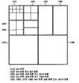
- FIG. 11 is an exemplary diagram illustrating a block type of a sub block for an extended macroblock of 64 ⁇ 64 pixels according to an embodiment of the present invention.
- the extended macroblock is a 64x64 pixel block and the optimal block type after intra prediction is determined as shown in FIG. 11, 4x4 transform is performed for blocks 0-7 and blocks 8-block are performed. 8x8 transform is performed for 12, and 4x4 transform is performed in 4x4 pixel units within a 16x16 pixel block for blocks 13 to 18, and each 4x4 transform is performed in each 16x16 pixel block. The conversion is again performed on the DC component block in which the DC components of the blocks are assembled.
- 4 ⁇ 4 transform is performed as in the case of intra prediction of 16 ⁇ 16 pixels or more, and then 4 ⁇ 4 transform is performed once more for the DC component block.
- the residual block of the macroblock of the chrominance component is divided into a residual block having 8x8 pixels (hereinafter referred to as an '8x8 pixel residual block') and four 4x4 pixels remaining in each 8x8 pixel residual block.
- 4 ⁇ 4 transform is performed on the block.
- DC components of four 4x4 transform blocks in an 8x8 pixel residual block gather to form a DC component block having a 2x2 transform coefficient, and 2x2 transform is performed on the DC component block.
- the types of 4x4 transforms for the 8x8 pixel residual block and 2x2 transforms for the DC component block may be different.
- the efficiency is high depending on the size of the sub-block used for intra prediction in units of 16 ⁇ 16 pixel blocks.
- the encoder 140 it is preferable that the encoder 140 generates transform type data by generating and encoding a transform type for identifying the type of the transform selected for each block. Transform type data is included in the encoded data. However, different transforms cannot be used within a 16x16 pixel block.
- a 16 ⁇ 16 pixel block is divided into 8 ⁇ 8 pixel blocks, and one or more 8 ⁇ 8 pixel blocks among four 8 ⁇ 8 pixel blocks are divided into subblocks smaller than 8 ⁇ 8 pixels.
- only 4x4 transform may be used for the 16x16 pixel block, and in this case, the transform type is not encoded.
- 4 ⁇ 4 transform and 8 ⁇ 8 transform are performed on the 16 ⁇ 16 pixel block, so that a transform having a low encoding cost is selected.
- a transformation type (for example, may be represented by 1 bit) indicating a type of may be encoded.
- a subblock of 16 ⁇ 16 pixels or more 4 ⁇ 4 transform, 8 ⁇ 8 transform, and 16 ⁇ 16 transform are performed so that the transform having the smallest encoding cost is selected, and a transform type (for example, 1) Bit or 2 bits) may be encoded.
- a transform type for example, 1) Bit or 2 bits
- FIG. 12 is an exemplary diagram for describing an encoding method of an inter picture and related data to be transmitted through encoded data according to an embodiment of the present invention.
- all block types of FIG. 4 may be used for motion estimation, and within an extended macroblock, it may be selected whether it is intra mode or inter mode in units of 16 ⁇ 16 pixel blocks. That is, both intra mode and inter mode may be used in an extended macroblock of a P-picture or a P-slice.
- L0 prediction (List 0 Prediction, mainly used for forward prediction) is used as forward prediction
- L1 prediction (List 1 Prediction, mainly used for backward prediction) is used as backward prediction.
- the extended macroblock is a 32 ⁇ 32 pixel block
- whether to perform encoding in units of 32 ⁇ 32 pixel blocks or encoding in units of 16 ⁇ 16 pixel blocks may be indicated through an extended macroblock flag (extended_mb_flga).
- extended macroblock flag is 1, the encoding is performed in units of 32 ⁇ 32 pixel blocks, and when the extended macroblock flag is 0, encoding is performed in units of 16 ⁇ 16 pixel blocks. can do.
- the extended macroblock flag is 0, the extended macroblock may be divided into four 16 ⁇ 16 pixel blocks to determine whether it is an intra mode or an inter mode for each 16 ⁇ 16 pixel block.
- each 16x16 pixelblock unit may be divided into smaller subblocks to perform encoding.
- the motion estimator 116 of the inter predictor 114 of the predictor 110 finds a block most similar to the current block that is the current encoding target in the current picture, that is, a reference block within the reference picture, for the current block.
- a motion vector (MV) indicating a relative position of the reference block is output. This process is called motion estimation, and motion estimation generates a motion vector by comparing subblocks in a macroblock with one or more reference pictures in the picture buffer 180.
- the 8x8 pixel block may use different reference pictures, but the subblocks in the 8x8 pixel block use the same reference picture.
- the motion vector is encoded by the encoder 140 and included in the encoded data.
- the encoder 140 uses a median of motion vectors of neighboring blocks of the current block as a predicted motion vector (PMV). Only the differential motion vector (DMV), which is a difference vector between the predicted motion vector and the motion vector of the current block, is encoded to generate motion information data.
- the encoder 140 may further encode not only a differential motion vector but also a reference picture index. That is, the motion information may include a differential motion vector and a reference picture index, and the encoder 140 may encode the motion information to generate motion information data and include the motion information data in the encoded data.
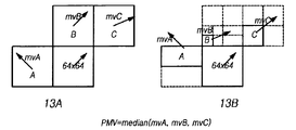
- FIG. 13 is an exemplary view for explaining a process of determining a predicted motion vector according to an embodiment of the present invention.
- 13A illustrates the motion vector of the neighboring block used to determine the motion vector and the predictive motion vector of the current block when both the current block and the neighboring block are 64 ⁇ 64 pixel blocks.
- the median of the motion vectors of the neighboring block may be determined as the predicted motion vector as in the conventional method.
- 13B illustrates the motion vector of the neighboring block used to determine the motion vector and the predictive motion vector of the current block when the sizes of the current block and the neighboring block are different. If the size of the current block and the neighboring block is different, it is necessary to select which neighboring block to determine the prediction motion vector.
- the motion vector mvA of the block A located on the upper right side is used for prediction
- the motion vector mvB of the lowermost left block B is used for prediction when the neighboring blocks at the top are divided into several
- the motion vector mvC of C is used for prediction.
- the prediction motion vector may not be determined using the block B and the block C.
- the motion vector of the block is used to determine a predicted motion vector.
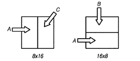
- FIG. 14 is an exemplary diagram for describing a process of determining a predicted motion vector of an 8x16 pixel block and a 16x8 pixel block according to an embodiment of the present invention.
- the median value is not used. That is, when the current block is an 8x16 pixel block, block A is used as the neighboring block on the left side and block C is used to determine the predictive motion vector as the neighboring block on the right side. If the current block is a 16x8 pixel block, the upper neighboring block uses block B and the lower neighboring block uses block A to determine the predicted motion vector.
- the SKIP mode is used for macroblocks that are 16 ⁇ 16 or more pixel blocks.
- the macroblock which is a 16 ⁇ 16 pixel block or more
- motion estimation and compensation are performed using the predicted motion vector.
- the predictive motion vector is determined as 0.
- the predicted motion vector of the current block is (0). , 10).
- the extended macroblock is shown in FIG.
- the predicted motion vector is obtained using the left block and the upper block of the actual image block (16x16 pixel block), and the motion prediction and compensation for the actual image block are performed using the predicted motion vector.
- the optimal encoding mode of the extended macroblock that is the current encoding target is the SKIP mode, skip32_flag is decoded and the next extended macroblock is encoded.
- the subtractor 120 subtracts the current block and the reference block indicated by the motion vector of the current block estimated by the motion estimator 116 to generate a residual block
- the transformer and quantizer 130 subtracts the subtractor.
- the residual block generated by 120 is transformed and quantized, and the encoder 140 generates encoded data by entropy encoding the quantized transform coefficients.
- the transformer and quantizer 130 performs one or more transforms and quantizations according to the size of the current block, selects the most efficient transform type, and generates transform and quantized transform coefficients according to the selected transform type. do.
- the encoder 140 generates transform type data by generating and encoding a transform type for identifying a type of a transform selected for each block. Transform type data is included in the encoded data. However, different transforms cannot be used within a 16x16 pixel block.
- a 16x16 pixel subblock is divided into 8x8 pixel blocks, and one or more 8x8 pixel subblocks of four 8x8 pixel subblocks are less than 8x8 pixels.
- only 4 ⁇ 4 transforms may be used for the remaining blocks of the 16 ⁇ 16 pixel subblocks, in which case the transform type is not encoded.
- 4 ⁇ 4 transform and 8 ⁇ 8 transform are performed on the remaining blocks of the 16 ⁇ 16 pixel subblock, so that a transform having a low encoding cost is selected.
- the transform type (for example, represented by 1 bit) indicating the type of the selected transform is encoded.
- the 4 ⁇ 4 transform, 8 ⁇ 8 transform, and 8 ⁇ 16 transform are performed on the remaining blocks of the 16 ⁇ 16 pixel subblock, thereby encoding costs.
- the 16 ⁇ 16 pixel subblock is divided into two 16 ⁇ 8 pixel subblocks
- 4 ⁇ 4 transform and 8 ⁇ 8 transform are performed on the remaining blocks of the 16 ⁇ 16 pixel subblock.
- a 16x8 transform is performed to select the type of transform having the smallest encoding cost, and to encode a transform type (for example, represented by 1 bit or 2 bits) indicating the type of the selected transform.
- a subblock of 16 ⁇ 16 pixels or more 4 ⁇ 4 transform, 8 ⁇ 8 transform, and 16 ⁇ 16 transform are performed so that the transform having the smallest encoding cost is selected, and a transform type (for example, 1) Bit or 2 bits) is encoded.
- a transform type for example, 1) Bit or 2 bits
- encoding bits used for transform type encoding may be configured as shown in Table 1 below.
- the transform Encoding bits used for type encoding may be configured as shown in Table 2.
- FIG. 15 is an exemplary diagram illustrating types of usable transforms and units in which transform types are encoded according to subblock sizes according to an embodiment of the present invention.
- an extended macroblock is 64 ⁇ 64 pixels and an extended macroblock is divided into subblocks of various sizes.
- the first 16x16 pixel block 1510 of the macroblock is divided into 4x4 pixel subblocks smaller than the 8x8 pixel block, the only available transform is a 4x4 transform, in which case the transform type is It is not encoded.
- the second 16 ⁇ 16 pixel block 1520 is divided into four 8 ⁇ 8 pixel subblocks, one of the 4 ⁇ 4 transforms or the 8 ⁇ 8 transform has a smaller encoding cost, and a transform type indicating the type of the selected transform is selected. Is encoded.
- the third 16 ⁇ 16 pixel block 1530 is divided into two 8 ⁇ 16 pixel subblocks, one of the 4 ⁇ 4 transform, the 8 ⁇ 8 transform, or the 8 ⁇ 16 transform has the smallest encoding cost.
- a transform type representing is encoded. Since the fourth 16 ⁇ 16 pixel block 1540 is divided into two 16 ⁇ 8 pixel subblocks, one of the 4 ⁇ 4 transform, the 8 ⁇ 8 transform, or the 16 ⁇ 8 transform having the lowest coding cost is selected.
- a transform type representing is encoded.
- the fifth 16 ⁇ 32 pixel block (1550), the sixth 16 ⁇ 32 pixel block (1560), the seventh 32 ⁇ 32 pixel block (1570), and the eighth 32 ⁇ 32 pixel block (1580) are all 16 ⁇ 16 pixel blocks.
- the 8x8 transform, or the 16x16 transform Since it is larger than the 4x4 transform, the 8x8 transform, or the 16x16 transform, one having a smaller encoding cost is selected, and a transform type indicating the type of the selected transform is encoded.
- the conversion type may be selected in units of 16x16 pixel blocks.
- a plurality of transform types are encoded for a 16x16 pixel block in which an encoded block pattern in a pixel block larger than a 16x16 pixel block such as a 32x32 pixel block is not zero.
- the residual block transformed and quantized by the transformer and quantizer 130 is inversely quantized and inversely transformed by the inverse quantizer and inverse transformer 150 to restore the residual block, and the adder 160
- the current block is reconstructed by adding the reconstructed residual block and the predicted block predicted by the predictor 110.
- the filter 170 performs filtering using a deblocking filter, etc., on the pictures created by accumulating the current blocks restored by the adder 160, and the filtered pictures are stored in the picture buffer 180 to refer to the next picture. It is used as a picture.
- 16 is an exemplary diagram illustrating a block boundary to perform deblocking filtering according to an embodiment of the present invention.
- 16A to 16E represent block boundaries for performing deblocking filtering on 16 ⁇ 16 pixel blocks using 4 ⁇ 4 transform, 8 ⁇ 8 transform, 8 ⁇ 16 transform, 16 ⁇ 8 transform, and 16 ⁇ 16 transform.
- a 16x16 pixel block using the 4x4 transform shown in 16A is subjected to deblocking filtering at the left and top block boundaries of each 4x4 pixel block, and 16x16 using the 8x8 transform shown in 16B.
- Pixel blocks have deblocking filtering on the left and top block boundaries of each 8x8 block, and 16x16 pixel blocks with the 8x16 transform shown in 16C are used on the left and top of each 8x16 pixel block.
- Deblocking filtering is performed at the block boundary, and the 16x16 pixel block using the 16x8 transform shown in 16D is deblocked filtering is performed at the left and top block boundaries of each 16x8 pixel block.
- deblocking filtering is performed on the left and upper block boundaries of the 16 ⁇ 16 pixel block.
- 17 is an exemplary diagram illustrating syntax of an intra picture according to an embodiment of the present invention.
- the encoded data of the intra picture is divided into a partition type, an intra prediction mode, and a CBPX_flag / CBP coded block pattern X-flag / Coded. Fields such as a block pattern and a transform coefficient.
- the encoder 140 of the image encoding apparatus 100 encodes the segmentation type information, the intra prediction mode, the CBPX_flag / CBP, the transform coefficient, and the like, and assigns them to each field to generate encoded data.
- the syntax of the encoded data for the intra picture shown in FIG. 17 is merely exemplary, and the syntax of the encoded data for the intra picture is not necessarily configured as shown in FIG. 17. That is, it should be appreciated that some or all of the syntax of the encoded data for the intra picture may be changed differently from that shown in FIG. 17, and some syntax may be omitted.
- the encoding of the CBPX_flag is performed.
- Omission and increase / decrease information ⁇ pq for the quantization parameter may be encoded.
- the increase / decrease information on the quantization parameter may be encoded in an extended macroblock unit, and the CBP information may be encoded in a 16 ⁇ 16 pixel block unit.
- split type data which is data in which split type information of a macroblock indicating a macroblock is divided into subblocks, is allocated to a split type field.
- the partition type information may be generated using the partition type number shown by way of example in FIG. 18.
- the division type number 2 is assigned to a (N / 2 k ) ⁇ (N / 2 k ) pixel block. If (N / 2 k ) ⁇ (N / 2 k ) pixel blocks of macroblock layer K are divided into four (N / 2 k + 1 ) ⁇ (N / 2 k + 1 ), The division type number 3 is assigned to a (N / 2k ) ⁇ (N / 2k ) pixel block.
- numbers such as 0, 1, 2, 3, and the like indicated in the divided subblocks in the (N / 2 k ) ⁇ (N / 2 k ) pixel blocks of each macroblock layer K are partitions for identifying each subblock. Part number.
- each partition type is assigned in the order of the smallest to the largest order.
- the partition type number of FIG. 18 is merely an example and may be allocated from the larger number to the smaller number in order of occurrence.
- the partition type number may be allocated according to the occurrence probability of each partition type, or the partition type number may be adaptively changed.
- each divided block may be divided into smaller blocks. For example, if a 32x32 pixel block is divided into four 16x16 pixel blocks by partition type number 3, each 16x16 pixel block is divided into smaller subblocks using the partition type-specific number in FIG.
- a division type number of the upper pixel block that is, a division type number different from the division type number of the 32 ⁇ 32 pixel block may be used.
- subblocks larger than 16 ⁇ 16 pixel blocks for example, 64 ⁇ 32 pixel blocks, 32 ⁇ 64 pixel blocks, and 16 ⁇ 32 pixels
- Coding of a partition type number for a block, a 32x16 pixel block, etc. may be omitted.
- FIG. 19 is a diagram illustrating a split type number coding sequence in the case of dividing an expanded macroblock into subblocks of various sizes according to an embodiment of the present invention.
- the extended macroblock is a 64 ⁇ 64 pixel block and the maximum number of partitioned layers is four.
- the partition type information of the macroblock may be sequentially encoded according to the partition type number encoding order in order to encode the partition type information of the macroblock. .
- a process of dividing the macroblocks shown in FIG. 19 for each of the divided layers may be shown as shown in FIG. 20.
- a 64 ⁇ 64 pixel subblock is divided into four 32 ⁇ 32 pixel subblocks, and in layer 1 (L1), L1-P0 (macroblock layer 1).
- Subblocks of partition number 0) and subblocks of L1-P3 are further divided into four 16 ⁇ 16 pixel subblocks, and L1-P1 (partition number 1 of macroblock layer 1).
- the subblock of and subblocks of L1-P2 are divided into 16x32 pixel subblocks and 32x16 pixel subblocks, respectively. Since the subblocks of L1-P1 and L1-P2 are divided into two subblocks, and are no longer divided, the partition number for each layer is not represented.
- layer 2 the subblock of L2-P0 (partition number 0 of macroblock layer 2) is further divided into four 8 ⁇ 8 pixel subblocks and L2-P3 (partition number 3 of macroblock layer 2) It is divided into two 16x8 pixel subblocks.
- the subblocks of L3-P0 (partition number 0 of macroblock layer 3) and the subblocks of L3-P1 (partition number 1 of macroblock layer 3) are each 4 4 ⁇ . It is divided into 4 pixel subblocks.
- the L1-P1 block and the L1-P2 blocks are divided into L1 instead of being divided into 16 ⁇ 32 pixel subblocks and 32 ⁇ 16 pixel subblocks, respectively.
- encoding may be performed in units of four 16 ⁇ 16 pixel blocks.
- 21 is an exemplary diagram for describing a process of sequentially encoding a split type number for each layer of a macroblock.
- the partition type information of the macroblock shown in FIG. 19 may be encoded as shown in FIG. 21.
- numerals written in ' ⁇ ' indicate an order of encoding division type numbers of respective subblocks. If the split type number for each layer for the extended macroblock is sequentially encoded according to the split type number encoding order, the split type number for each layer may be sequentially encoded in the order shown in FIG. 21.
- division type number 3 is encoded. Since the first 32x32 pixel subblocks L1-P0 of the four 32x32 pixel subblocks in the 64x64 pixel subblock are also divided into four 16x16 pixel subblocks, the partition type number 3 is encoded. The first 16 ⁇ 16 pixel subblocks L2-P0 of the four 16 ⁇ 16 pixel subblocks in the first 32 ⁇ 32 pixel subblocks L1-P0 of Layer 1 are also divided into four 8 ⁇ 8 pixel subblocks.
- the four 8x8 pixel blocks L3-P0, L3-P1, L3-P2, and L3-P3 in the corresponding 16x16 pixel subblocks L2-P0 are no longer small subblocks. Since it is not divided by, the partition type numbers ⁇ 3, 3, 0, 0 ⁇ are encoded respectively. Since subblocks of the layer 3 cannot be divided into smaller subblocks, the partition type numbers of the subblocks belonging to the layer 3 are not encoded.
- the division type of the second 16 ⁇ 16 pixel subblock L2-P1 and the third 16 ⁇ 16 pixel subblock L2-P2 of the macroblock layer 2 is encoded.
- the number is encoded, but since the partition is no longer divided into small blocks, the partition type number 0 is encoded.
- the fourth 16x16 pixel subblock L2-P3 is divided into 16x8 pixel subblocks, but since the partition type number is not 3, only the partition type number 1 is encoded.
- the partition type numbers of the four subblocks in the layer 2 are all encoded, the partition type numbers of the second 32 ⁇ 32 pixel subblocks L1 to P1 of the layer 1 are encoded, and the second 32 ⁇ 32 pixel subblock of the layer 1 is encoded.
- (L1-P1) is divided into 16x32 pixel subblocks, and since each divided subblock is no longer divided into small subblocks, the partition type number 2 is encoded.
- the third 32 ⁇ 32 pixel subblock L1-P2 of macroblock layer 1 the fourth 32 ⁇ 32 pixel subblock L1-P3 of macroblock layer 1, and the four 16 ⁇ 16 subordinates thereof.
- the division type numbers of the pixel subblocks L2-P0, L2-P1, L2-P2, and L2-P3 are sequentially encoded, ⁇ 1, 3, 0, 0, 0, 0 ⁇ is encoded.
- the partition type number ⁇ 3, 3, 3, 3, 3, 0, 0, 0, 0, 0, 1, 2, 1, 3, 0, 0, 0, 0 ⁇ is encoded.
- the split type number may be encoded into a binary bit string using lossless compression coding such as binary arithmetic coding or Huffman coding.
- each partition type number may use a different binary value according to the layer number of the partition type number to be currently encoded. If the layer number is log 2 (N / 16) or less, Table 3 may be used. If the layer number is larger than log 2 (N / 16), table 4 may be encoded. For example, since the partition type number 3 of the subblocks L1 to P0 of FIG. 11 may be represented by the binary number '01', referring to Table 3, the partition type number 3 may be arithmetic encoded by the binary numbers '0' and '1', respectively. Can be encoded.
- the partition type number 0 of the subblock L3-P2 belonging to the subblock L2-P0 may be represented by the binary number '1' referring to Table 4, the partition type number 3 is arithmetic encoded by the binary number '1'. Can be encoded.
- an intra prediction mode is data in which information about an intra prediction mode is encoded in an intra prediction mode field. The data is allocated.
- 22 is an exemplary diagram illustrating a coding order of an intra prediction mode according to an embodiment of the present invention.
- FIG. 22 illustrates a case in which the expanded macroblock is a 64x64 pixel block and the number of maximum division layers is 4 as shown in FIG.
- the intra prediction mode for each subblock of the extended macroblock is sequentially encoded according to the encoding order of the intra prediction mode shown in FIG. 22 to generate intra prediction mode data. can do.
- the number indicated in each subblock indicates the encoding order of the intra prediction mode for encoding the intra prediction mode.
- encoding is performed on a 64 ⁇ 64 pixel extended macroblock in units of 16 ⁇ 16 pixel blocks, a 32 ⁇ 32 pixel block corresponding to the 15th and 16th blocks, or the 17th and 18th blocks
- encoding may be performed by dividing each of four 16x16 pixel blocks into units like the 19th to 22nd blocks.
- a prediction mode flag indicating whether the prediction direction of the current block estimated from the neighboring block and the prediction direction of the selected current block is the same is encoded. If the prediction mode flag is not the same as the prediction direction of the current block estimated from the neighboring block and the prediction direction of the current block estimated from the neighboring block indicates that the prediction direction of the current block and the prediction direction of the current block estimated from the neighboring block are not the same.
- the intra-prediction mode data is produced.
- intra prediction is performed by dividing the expanded macroblock into subblocks other than 4 ⁇ 4 pixel blocks, 8 ⁇ 8 pixel blocks, or 16 ⁇ 16 pixel blocks
- prediction is performed using the left block and the upper block of the current block.
- the prediction mode number of one current block is 3 or more
- the prediction direction of the current block may use prediction mode number 2 (DC mode) of FIG. 9.
- intra prediction mode data is generated.
- intra prediction mode data is generated by encoding the number of the prediction mode of the block as the intra prediction mode. In this way, the intra prediction mode data for each subblock of the macroblock generated by encoding in the order shown in FIG. 22 is allocated to the intra prediction mode field shown in FIG.
- FIG. 23 is an exemplary diagram for explaining an example of a process of encoding an intra prediction mode of a macroblock according to an embodiment of the present invention.
- the current macroblock to be encoded is a 64 ⁇ 64 pixel block, and is divided into subblocks of various sizes and shapes as shown.
- the neighboring block on the left side of the current macroblock is intra predicted in units of 64 ⁇ 64 pixels.
- the prediction mode number of the left neighboring block is 0 (vertical mode)
- the upper neighboring block of the current macroblock is intra predicted in units of 64 ⁇ 64 pixels
- the prediction mode number of the left neighboring block is 1 (horizontal mode). Illustrated illustratively.
- the number displayed in each subblock in the current extended macroblock indicates a prediction mode number of each subblock.
- the prediction mode number of the first 4x4 pixel subblock of the current extended macroblock is 2 (DC mode), and the prediction mode number of the corresponding subblock estimated using the neighboring block on the left and the upper one is 0. . That is, since 0 of the prediction mode number 0 of the left neighboring block and the prediction mode number 1 of the upper neighboring block is smaller, the prediction mode number of the first 4x4 pixel subblock is estimated to be zero. Since the prediction mode of the first 4x4 pixel subblock is different from the prediction mode of the corresponding subblock estimated from the neighboring block, the prediction direction of the corresponding subblock and the prediction direction of the corresponding subblock estimated from the neighboring block are not the same.
- a prediction mode flag indicating and a prediction mode number 2 which is a prediction mode number of the corresponding subblock are encoded as an intra prediction mode of the corresponding subblock.
- the prediction mode number of the second 4x4 pixel subblock is 1 and the prediction mode number of the corresponding subblock estimated from the neighboring block is 1, so that the prediction direction of the corresponding subblock and the prediction direction of the corresponding subblock estimated from the neighboring block are the same. Therefore, only the prediction mode flag indicating that the prediction directions are the same is encoded as the intra prediction mode of the corresponding subblock.
- the intra prediction mode of the next subblock is encoded according to the encoding order of the intra prediction mode shown in FIG. 22.
- the prediction mode number of the third 4x4 pixel subblock is 0, and the corresponding subblock estimated from the neighboring block. Since the prediction mode number of 0 is 0, the prediction direction of the corresponding subblock and the prediction direction of the corresponding subblock estimated from the neighboring block are the same, so that only the prediction mode flag indicating the same prediction direction is encoded as the intra prediction mode of the corresponding subblock. do.
- the eleventh 16x16 pixel subblock the prediction flag is not encoded, and prediction mode number 1 of the subblock is encoded as the intra prediction mode of the subblock.
- the 15th and 16th blocks are divided into 16x32 pixel blocks and encoded in an intra prediction mode
- the 17th and 18th blocks are divided into 32x16 pixel blocks and encoded in an intra prediction mode. Shown. However, when intra prediction coding is performed on an extended macroblock in units of 16 ⁇ 16 pixel blocks, the 15th and 16th blocks, or the 17th and 18th blocks for subblocks larger than 16 ⁇ 16 pixel blocks are performed. The pixel block division of a rectangle as described above is omitted.
- 23B exemplarily shows intra prediction mode data included in an intra prediction mode field when encoding an intra prediction mode of a current macroblock as shown in 23A.
- the prediction mode flag and the prediction mode number are encoded for the first 4x4 subblock, and only the prediction mode flag is encoded for the second, third, and fourth 4x4 subblocks.
- the intra prediction mode data is assigned to the intra prediction mode field.
- intra prediction coding is performed by dividing the extended macroblock into rectangular sub-blocks (for example, 16 ⁇ 32, 32 ⁇ 16, etc.) larger than 16 ⁇ 16 pixel blocks.
- the coded block pattern flag (CBPX_flag: Coded Block Pattern X_flag, hereinafter referred to as 'CBPX flag') and CBP (CBP: Coded Block Pattern, hereinafter referred to as 'CBP') are encoded by considering the size of the subblock.
- CBPX_flag / CBP field can be assigned.
- the CBP data allocated to the CBPX_flag and the CBP field indicates whether a non-zero quantized transform coefficient is included in a subblock of the macroblock.
- intra prediction encoding is performed by dividing the expanded macroblock into units of 16 ⁇ 16 pixel blocks as shown in FIG. 5, encoding of the block pattern flag is omitted and encoding ⁇ pq for the quantization parameter is encoded. can do.
- the increase / decrease information on the quantization parameter may be encoded in an extended macroblock unit, and the CBP data may be encoded in a 16 ⁇ 16 pixel block unit.
- 24 is an exemplary diagram for describing a process of encoding a CBPX_flag and a CBP for an intra macroblock according to an embodiment of the present invention.
- the encoder 140 of the image encoding apparatus 100 determines whether the size of the subblock of the extended macroblock is one of 64 ⁇ 64, 64 ⁇ 32, and 32 ⁇ 64 (S2410), and the size of the subblock is 64. If it is not one of x64, 64x32, and 32x64, it is determined whether the size of the subblock is one of 32x32, 32x16, and 16x32.
- step S2410 when intra prediction is performed by dividing the extended macroblock into units of 16 ⁇ 16 pixels, in step S2410, is the size of the subblock 64 ⁇ 64 pixel blocks, that is, whether intra prediction coding is performed in units of the extended macroblock?
- operation S2420 when the size of the sub block is not a 64 ⁇ 64 pixel block, it may be determined whether the size of the sub block is a 32 ⁇ 32 pixel block. As a result of the determination in step S2420, if the size of the subblock is one of 32x32, 32x16, and 16x32 or 32x32 pixel block, it is determined whether there is a non-zero transform coefficient in the subblock (S2430).
- a CBP32 flag (for example, may be represented by 1 bit such as '1') indicating that a non-zero coefficient to be encoded is encoded in the corresponding subblock (S2440).
- the CBP is encoded in units of 16 ⁇ 16 pixels (S2450).
- the CBP32 flag indicating that there is no nonzero transform coefficient in the subblock (for example, , Which may be represented by 1 bit, such as '0' (S2460).
- the CBP64 flag is a flag indicating the presence or absence of a coefficient to be encoded that is not zero in a 64x64 pixel block.
- the CBP32 flag is a flag indicating the presence or absence of a non-zero coefficient to be encoded in a 32x32 pixel block.
- Such a CBPX flag indicates whether the luminance component blocks have a non-zero transformation coefficient since the transform type does not need to be transmitted when the residual block of the luminance component does not have a nonzero transformation coefficient. Used to.
- CBP is encoded in units of 16x16 pixel blocks, and indicates whether there is a non-zero transform coefficient for each 8x8 pixel block in the 16x16 pixel block using 1 bit per 8x8 pixel block. For example, 1 bit indicates whether there are non-zero transform coefficients in two 2x2 color difference component DC blocks, and 1 bit indicates whether there are non-zero transform coefficients in two 8x8 color difference component AC blocks. It is shown.
- step S2420 if the size of the subblock is not one of 32x32, 32x16, and 16x32 or is not a 32x32 pixel block, the process proceeds to step S2450 to encode the CBP.
- the size of the sub block when the size of the sub block is not a 32 ⁇ 32, 32 ⁇ 16 or 16 ⁇ 32 pixel block, it may be determined whether the size of the sub block is a 16 ⁇ 16, 16 ⁇ 8 or 8 ⁇ 16 pixel block. If the subblock is a 16 ⁇ 16, 16 ⁇ 8, or 8 ⁇ 16 pixel block, and there are coefficients to be encoded other than zero in the corresponding subblock, the CBP16 flag (for example, '1' may be represented by 1 bit). Otherwise, the CBP may be encoded in units of 16 ⁇ 16 pixel blocks without using the CBP flag.
- step S2410 if the size of the subblock is one of 64 ⁇ 64, 64 ⁇ 32, and 32 ⁇ 64 or is a 64 ⁇ 64 pixel block, it is determined whether there is a non-zero transform coefficient in the subblock (S2470). If there is a non-zero transform coefficient in the subblock, a CBP64 flag indicating that there is a non-zero transform coefficient (for example, may be represented by 1 bit such as '1') is encoded (S2480). If there are no non-zero coefficients to encode, a CBP64 flag indicating that there are no non-zero coefficients to be encoded (for example, may be represented by 1 bit as '0') is encoded (S2490).
- the CBP64 flag is a flag indicating whether a non-zero quantized transform coefficient exists in a 64 ⁇ 64 pixel block.
- the CBP64 flag and the CBP32 flag may be omitted, and the increase / decrease information on the quantization parameter may be omitted.
- ⁇ pq can be encoded. In this case, it is preferable to encode the increase / decrease information for the quantization parameter in an extended macroblock unit.
- the conversion type is encoded when the CBP flag is not zero.
- the CBP is encoded, and when the CBP is not 0, the transform type applied in units of 16 ⁇ 16 pixel blocks is encoded.
- the CBP is encoded according to the transform type. If 16 ⁇ 16 transform is used, only the CBP 2 bits of the chrominance component are encoded. If 8 ⁇ 16 or 16 ⁇ 8 transform is used, two 8 ⁇ 16 or 16 ⁇ 8 pixel blocks within the 16 ⁇ 16 pixel block Encodes 2 bits of CBP indicating whether a transform coefficient is nonzero. However, in exceptional cases, when the CBP bit of the first divided block of the two divided blocks is 0, the CBP bits of the second divided block may not be encoded.
- 25 is an exemplary view showing the structure of a CBP according to an embodiment of the present invention.
- FIG. 25 exemplarily illustrates a structure of a CBP when an input image has a 4: 2: 0 format. If there is no non-zero transform coefficient in the first 8x8 pixel block (Y0) of the luminance component, the least significant bit (LSB) of the CBP is zero, and zero in the second 8x8 pixel block (Y1). If there is a non-quantized transform coefficient, the second least significant bit of the CBP is one.
- the CBPs for the third 8x8 pixel block Y2 and the fourth 8x8 pixel block Y3 are allocated, and two 2x2 chrominance component DC blocks U (DC) and V (DC Since there is a nonzero quantized transform coefficient within)), the bit for chrominance DC is 1 and the nonzero quantized transform in two 8x8 chrominance component AC blocks (U-AC and V-AC) Since there is no coefficient, the bit for chrominance AC is zero.
- FIG. 26 is an exemplary diagram illustrating an example of a sequence of encoding a CBPX flag and a CBP according to an embodiment of the present invention.
- FIG. 26 exemplarily illustrates a coding sequence of a CBP64 flag, a CBP32 flag, and a CBP when an extended macroblock is a 64 ⁇ 64 pixel block and a size of a subblock currently being encoded is 64 ⁇ 64, 64 ⁇ 32, or 32 ⁇ 64.
- the dashed-dotted arrow indicates the order of progression when the CBPX flag is 0
- the dashed arrow indicates the order of progression when the CBPX flag is 1
- the solid arrow indicates the order of progressing without any condition. .
- the CBP64 flag is coded 0, and if the at least one quantized transform coefficient is not 0, the CBP64 flag is coded 1. If the CBP64 flag is 0, since there are no more CBPs to encode, the CBPX flag and CBP of the next macroblock are encoded. If the CBP64 flag is 1, the CBP32 flag of each 32x32 pixel subblock in the 64x64 pixel block is encoded. If the CBP32 flag is 1, the CBP of four 16x16 pixel blocks in the 32x32 pixel subblock is Is encoded.
- FIG. 27 is an exemplary diagram illustrating another example of a sequence of encoding a CBPX flag and a CBP for an intra macroblock according to an embodiment of the present invention.
- the encoding order of the CBP32 flag and CBP is exemplarily illustrated.
- the dashed-dotted arrow indicates the order of progression when the CBPX flag is 0
- the dashed arrow indicates the order of progression when the CBPX flag is 1
- the solid arrow indicates the order of progressing without any condition. .
- the encoder 140 of the image encoding apparatus 100 may only encode blocks having non-zero quantized transform coefficients after encoding a CBPX (X: integer greater than or equal to 32) flag and CBP.
- the encoded quantized transform coefficients are encoded to generate encoded image data. If the size of the block to be encoded is larger than the size of the transform, the quantized transform coefficients of the block are encoded in a raster scan order in the block.
- FIG. 28 is an exemplary diagram illustrating a coding order of quantized transform coefficients for each partition type according to an embodiment of the present invention.
- FIG. 28 exemplarily illustrates a procedure of encoding quantized transform coefficients when the encoding target block is a 32 ⁇ 32 pixel block.
- 16 ⁇ 16 transform for blocks larger than 16 ⁇ 16 pixels (4 ⁇ 4 transforms of 16 4 ⁇ 4 blocks within 16 ⁇ 16 blocks, and 4 ⁇ 4 transforms for 16 DC coefficients.
- the conversion is performed, and 16x16 conversion is performed for convenience of description), so that four 16x16 conversions are performed in the case of a 32x32 pixel block.
- two 16x16 transforms are performed for each 32x16 pixel block.
- two 16x16 transforms are performed for each 16x32 pixel block.
- 16x16 conversion is performed for each 16x16 pixel block.
- 29 is an exemplary diagram illustrating a syntax structure of encoded data for an inter picture according to an embodiment of the present invention.
- FIG. 29 exemplarily illustrates a syntax structure of encoded data generated by encoding according to an embodiment of the present invention when the input image is an inter picture.
- the encoded data for the inter picture according to an embodiment of the present invention includes one or more fields of a SKIP_N flag, a macroblock type, and a partition type, and is intra prediction when the extended macroblock is an intra macroblock. It further includes one or more fields of Mode, CBPX Flag / CBP, and Transform Coefficient, and if the extended macroblock is an inter macroblock, SKIPX flag, differential motion vector / reference picture index, CBPX flag, transform type, CBP, and transform It may be configured to further include one or more fields of the coefficients.
- the syntax of the encoded data for the inter picture shown in FIG. 29 is merely exemplary, and the syntax of the encoded data for the inter picture is not necessarily configured as shown in FIG. 29. That is, it should be appreciated that some or all of the syntax of the encoded data for the inter picture may be changed differently from those shown in FIG. 29, and some syntax may be omitted.
- the encoder 140 of the image encoding apparatus 100 encodes a SKIPN flag indicating whether a macroblock currently being encoded is a SKIP macroblock.
- N represents the size of the macroblock.
- the SKIP64 flag indicating whether the 64 ⁇ 64 pixel macroblock is a SKIP macroblock is encoded.
- the macroblock is a 32 ⁇ 32 pixel block, the 32 ⁇ 32 pixel macroblock is SKIP.
- the SKIP32 flag indicating whether or not it is a macroblock is encoded
- the SKIP16 flag indicating whether or not the 16x16 pixel macroblock is a SKIP macroblock is encoded.
- the macroblock is a SKIP macroblock, since the current macroblock has no data to be encoded, the next macroblock is encoded. If the macroblock is not a SKIP macroblock, a macroblock type flag indicating whether the macroblock is an intra macroblock or an inter macroblock is transmitted. For example, when the input image to be encoded is a P picture, the available macroblock types are I-macroblocks and P-macroblocks, and when the input image to be encoded is the B picture, the macroblock type is usable. Are I- and B-macroblocks.
- all block types of FIG. 4 may be used for motion estimation, and may be selected to be intra mode or inter mode in units of 16 ⁇ 16 pixel blocks within an extended macroblock. That is, both intra mode and inter mode may be used in an extended macroblock of a P-picture or a P-slice.
- an extended macroblock flag (extended_mb_flag).
- extended macroblock flag 1
- the encoding is performed in units of 32 ⁇ 32 pixel blocks
- the extended macroblock flag is 0, encoding is performed in units of 16 ⁇ 16 pixel blocks. can do.
- the extended macroblock flag is 0, the extended macroblock may be divided into four 16 ⁇ 16 pixel blocks to determine whether it is an intra mode or an inter mode for each 16 ⁇ 16 pixel block.
- each 16x16 pixelblock unit may be divided into smaller subblocks to perform encoding.
- FIG. 30 is a diagram illustrating an example of syntax used in a P-picture (or P-slice) according to an embodiment of the present invention.
- the expanded macroblock is assumed to be a 32x32 pixel block.
- skipX_flag and interX_flag may have different context tables according to X values.
- skip32_flag and skip16_flag may have different context tables. Detailed description thereof will be described later.
- the skipX_flag is a flag indicating whether or not the current block to be encoded is in the SKIP mode. As shown in Table 5, the skipX_flag may indicate whether or not the SKIP mode is in one bit. For example, when the encoding bit of skipX_flag is 1, this may indicate that the current block is in the SKIP mode.
- X means a number greater than or equal to 16 within the range of the extended macroblock.
- interX_flag is a flag indicating whether the current block to be encoded is intra mode or inter mode, and as shown in Table 6, whether the divided pixel blocks in the macroblock extended to 1 or 2 bits are intra mode or inter mode. It may indicate whether the mode.
- interX_flag when interX_flag is '00', this means that all the divided subblocks in the extended macroblock are in intra mode.
- the 32x32 pixel block which is an extended macroblock, is divided into four 16x16 pixel blocks, and each 16x16 pixel block is encoded by the above-described intra prediction coding method. Therefore, when all subblocks in the extended macroblock are intra modes, the block type of the divided subblock, the intra prediction mode of the luminance component and the chrominance component, the CBP, the quantization parameter, the transform coefficient, and the like may be encoded.
- extended_mb_flag 0
- the block type and MVD / ref_idx are encoded only for the 16 ⁇ 16 pixel block, not the SKIP mode, for each 16 ⁇ 16 pixel block.
- skip16_flag can be encoded using Table 5.
- each syntax may have a different context table.
- each of the 16 ⁇ 16 pixel blocks is mostly an inter mode or all intra modes in each 16 ⁇ 16 pixel block.
- the case where an intra mode sub block and an inter mode sub block exist simultaneously in a 16x16 pixel block can be ignored. Therefore, after encoding the division type of each 16x16 pixel block, the subblocks in the 16x16 pixel block in which inter16_flag is 0, that is, the intra mode, encode the luminance component and the chrominance component in the intra prediction mode.
- skip16_flag is encoded by using Table 5 for 16 ⁇ 16 pixel blocks having inter16_flag of 1, that is, inter mode.
- the reason of encoding skip16_flag after encoding the partition type is that the intra mode and the inter mode are present in the extended macroblock at the same time, which means that the texture exists in the inter mode.
- the mode is likely to be divided into small blocks, and therefore it is preferable to transmit the split type first and to encode skip16_flag only for pixel blocks whose size of the block is 16x16.
- the encoding order is not limited to this, and skip16_flag may be encoded first, and then the partition type may be encoded.
- CBPX_flag Subsequent encoding of CBPX_flag, transform type, CBP / quantization parameter, transform coefficient, etc. is the same as described above, and thus description thereof is omitted. However, in case of intra picture / slice or intra EMB, CBPX_flag may not be encoded.
- the extended macroblock is a 64x64 pixel block
- the subblock having a size of 16x16 or more after the partition type information of the current block to be encoded is encoded, similarly to the case where the extended macroblock is a 32x32 pixel block.
- SkipX_flag is coded only for these fields.
- X represents the size of a subblock such as 16 or 32. For example, if the macroblock is a 64x64 pixel block and is not in SKIP mode and the subblock size of the extended macroblock is one of 64x32, 32x64, and 32x32, then skip32_flag is set for each subblock. Is encoded.
- the size of the subblock of the extended macroblock that is 64x64 pixels is 64x32 or 32x64, two skip32_flag are encoded. If the size of the subblock is smaller than 32 ⁇ 32, skip32_flag is not encoded. When the size of the subblock is one of 32 ⁇ 16, 16 ⁇ 32, and 16 ⁇ 16, skip16_flag of each subblock is encoded.
- FIG. 31 is a diagram illustrating an example of syntax used in a B-picture (or B-slice) according to an embodiment of the present invention.
- a B-picture In a B-picture, up to two arbitrary reference pictures can be selected.
- the two sheets are called L0 prediction and L1 prediction, respectively, and each reference picture plays a different role.
- L0 prediction is used for forward prediction
- L1 prediction is used for backward prediction.
- the B-picture can use a picture before the current picture to be encoded and a picture after the picture to be encoded as a reference picture, and can use the two reference pictures at the same time (bidirectional prediction) to perform motion estimation and compensation.
- the block type used for the motion estimation all block types of FIG. 2 may be used, and whether the intra mode or the inter mode is selected in units of 16 ⁇ 16 pixel blocks in the macroblock extended in the same manner as the P-picture method.
- two pictures are not limited to the picture before the current picture and the picture after the picture, and any two pictures can be used as the reference picture regardless of before and after.
- the motion picture / compensation (bidirectional prediction) may be performed using the reference picture.
- Coding modes that can be used in a B-picture according to an embodiment of the present invention include intra mode, SKIP mode, direct mode, L0 prediction, L1 prediction, and bidirectional.
- the intra mode performs encoding using the same method as the above-described intra encoding method, and may select an intra mode in units of extended macroblocks or an intra mode in units of 16 ⁇ 16 pixel blocks within an extended macroblock.
- the SKIP mode transmits only a flag indicating that the current block to be encoded is a SKIP mode.
- the SKIP mode may be used for blocks of 16 ⁇ 16 pixels or more, such as 16 ⁇ 16 pixel blocks, 32 ⁇ 32 pixel blocks, etc., and motion compensation is performed using the predicted B_pred_dir, the predicted motion vector MVD, the predicted ref_idx, and the like.
- the reference block obtained through the motion compensation becomes a reconstructed block.
- B_pred_dir is a prediction direction of the B-picture, and means both directions of L0 and L1.
- the direct mode encodes only the flag indicating the direct mode and data related to transform coefficient encoding (for example, CBPX_flag / CBP, quantization parameter, transform type, transform coefficient, etc.). That is, the direct mode is an encoding mode in which motion information is omitted, and a direct mode can be used for blocks of 8x8 pixel blocks or more, such as 8x8, 16x16, 32x32, and the like. In this case, motion estimation and compensation perform motion estimation and compensation in units of (N / 2) ⁇ (N / 2) pixel blocks. For example, in the 8x8 direct mode, motion estimation and compensation are performed in units of 4x4 pixel blocks.
- transform coefficient encoding for example, CBPX_flag / CBP, quantization parameter, transform type, transform coefficient, etc.
- L0 prediction means one direction prediction using only L0 motion information
- L1 prediction means one direction prediction using only L1 motion information.
- Bidirectional prediction means prediction using two motion information of L0 and L1 using a mean value of two pictures as a reference picture.
- Motion estimation methods for B-pictures include motion estimation / compensation in direct prediction mode, motion estimation / compensation in SKIP mode, motion estimation / compensation in one-way prediction (L0 prediction or L1 prediction), and motion estimation in bidirectional prediction. / Compensation method.
- the motion estimation / compensation method of the direct prediction mode is described.
- the direct mode the motion estimation / compensation method of the temporal direct prediction mode using the motion information correlation in the time direction, and the spatial direction (horizontal and vertical two-dimensional space)
- the temporal direct prediction mode or the spatial direct prediction mode is used by selecting one slice unit rather than a macroblock unit or a block unit.
- a reference picture having the smallest reference number of L1 prediction is important and is called an anchor picture.
- the nearest reference picture in the reverse direction of the target picture becomes an anchor picture, and a block at the same spatial location as the target block in the anchor picture is called an anchor block.
- the motion information of the anchor block is examined and the L0 motion vector of the anchor block is mvCol (MV of the Co-located block). If there is no L0 motion vector of the anchor block and it has an L1 motion vector, the motion vector of L1 is used as mvCol.
- the L0 reference picture in temporal direct prediction mode is a picture referred to by mvCol
- the L1 reference picture in temporal direct prediction mode is an anchor picture.
- the motion vector mvL0 of L0 and the motion vector mvL1 of L1 are obtained from the motion vector mvCol.
- the sizes of mvL0 and mvL1 are proportional to the intervals of the reference picture, the target picture, and the anchor picture, and are thus obtained by proportional allocation. That is, mvL0 can be obtained by using Equation 5 using the interval tb between the reference picture and the target picture and the interval td between the reference picture and the anchor picture.
- the anchor picture which is the reference picture of the smallest reference number in the L1 prediction and the anchor block at the same spatial location as the anchor picture are used to obtain the motion vector.
- the motion vector of the target block is predicted from the motion vector encoded in the target picture.
- the motion block information can be obtained by introducing a part of the concept of temporal direct prediction mode, i) the motion vector size of the anchor block is ⁇ 1 pixel or less both horizontally and vertically, and ii) the reference number of the anchor block reference picture 0, iii) L0 motion vector mvL0 and L1 motion vector mvL1 are set to 0 when the reference picture with the minimum reference number at L0 satisfies the condition that both are short-term reference pictures, and the picture having the smallest reference number in L0 prediction is L0.
- the picture having the smallest reference number in the prediction picture and L1 is referred to as the L1 prediction picture.
- the motion vectors mvL0 and mvL1 of the target block, and the L0 picture and the L1 picture, which are reference pictures are obtained from the encoded motion vectors in the target picture.
- the median value of the horizontal and vertical components is calculated using the L0 prediction motion vectors mvA, mvB, and mvC located at the left, top, and left upper corners, and the value is mvL0.
- the median values of the horizontal and vertical components are calculated using the L1 prediction motion vectors mvA, mvB, and mvC of the left, top, and right upper corners, and the values are mvL1. If the neighboring block is a unidirectional prediction or an intra coded L0 prediction, or there is no motion vector of the L1 prediction, it is replaced with a zero vector.
- the minimum reference number values of the motion vectors mvA, mvB, and mvC of the left, upper, and upper right corners are calculated, and the reference number of the N ⁇ N block is calculated.
- the process of obtaining this reference number is also performed independently of the L0 prediction and the L1 prediction.
- the neighboring block is unidirectional prediction or when there is no motion vector of L0 or L1 prediction that is intra prediction coded, the block is excluded when obtaining a reference number.
- the process of obtaining the mvL0, mvL1, L0 reference picture and the L1 reference picture is performed in units of N ⁇ N pixel blocks when performing the direct prediction mode of the N ⁇ N pixel block. Whether to use motion vectors mvL0 and mvL1 or 0 vectors is determined in units of blocks.
- the SKIP mode performs motion prediction and compensation using the predicted motion vector, it is the same as the SKIP mode of the P-picture, but the motion vector used for the SKIP mode in the B-picture and the predicted motion vector of the Direct mode of the reference picture, Same as the reference picture. That is, the motion estimation / compensation method of the SKIP mode is the same as the motion estimation / compensation method of the aforementioned direct prediction mode.
- the difference between the direct mode and the SKIP mode is that the SKIP mode has no motion information and no conversion coefficient, and the direct mode has no motion information only.
- the motion estimation / compensation method of one direction prediction (L0 prediction or L1 prediction) is the same as the motion estimation and compensation method of the P-picture except that the reference picture is one of L0 and L1, the description thereof is omitted.
- L0 reference pictures and mvL0 are obtained using the above-described motion estimation / compensation method of the P-picture for pixel blocks having a size of 8x8 or more in a B-picture having motion information, and L0 prediction is performed. And mvL1 are obtained to perform L1 prediction. Also, the reference block indicated by mvL0 in the L0 reference picture obtained through the L0 prediction process and the average block of the reference block indicated by mvL1 in the L1 reference picture obtained through the L1 prediction process are used as reference blocks for mvL0 and mvL1. Bidirectional prediction can be performed.
- L1 prediction is performed on the motion information of L0 prediction to select the optimal mvL1 and L1 reference pictures for the mvL0 / L0 reference picture, and the reference block indicated by mvL1 in the selected L1 reference picture and the L0 prediction are obtained.
- Bidirectional prediction may be performed using an average block of the reference block indicated by mvL0 in the L0 reference picture as a reference block.
- an optimal mvL0 and L0 reference picture is selected for the mvL1 / L1 reference picture, and the reference block indicated by mvL0 in the selected L0 reference picture and L1 prediction are obtained.
- Bidirectional prediction may be performed using an average block of the reference block indicated by mvL1 in the L1 reference picture as a reference block.
- one bidirectional prediction mode having the best encoding efficiency is selected by comparing the encoding efficiency of the bidirectional prediction mode with respect to pixel blocks having a size of 8x8 or more in the B-picture having the motion information. For a pixel block having a size of 16 ⁇ 16 or more, the motion information of the above-described bidirectional prediction modes is found, and when the optimal coding mode is determined, transform, quantization, and entropy transform coefficient coding are performed to determine actual coding bits required for the mode. It is desirable to determine the bidirectional prediction mode using the prediction error.
- each pixel block of 8x8 or more may use a different reference picture, but subblocks in the 8x8 pixelblock use the same reference picture.
- the subtractor 120 generates a residual block by subtracting a current block and a reference block indicated by the motion vector of the current block estimated by the motion estimator 116, and the generated residual block is a transformer and a quantizer ( After being transformed and quantized by 130, the quantized transform coefficients are entropy coded by the encoder 140 to generate encoded data.
- the conversion method for the B-picture is the same as the above-described conversion method for the P-picture, a detailed description thereof will be omitted.
- FIG. 31 shows data to be transmitted through a bitstream of a B-picture (or B-slice) assuming that the expanded macroblock is a 32x32 pixel block.
- the transmission syntax of the B-picture (or B-slice) is similar to the transmission syntax of the P-picture (or B-slice) described with reference to FIG. 30, and only a part added to the syntax of the P-picture is described here.
- the directX_flag is a flag indicating whether the extended macroblock, the 16x16 pixel block or more, and the 8x8 pixel block are in the direct mode among the interblocks not in the SKIP mode.
- motion information is not encoded, and information related to transform coefficients is encoded.
- data of motion information for example, B_pdir, MVD, ref_idx, etc.
- B_pdir is information indicating the prediction direction (L0 prediction, L1 prediction, bidirectional prediction) of the current block.
- the B_pdir is encoded only for inter blocks, not in SKIP or direct mode, and has three modes as shown in Table 9 below.
- both the motion information (mvL0, ref_idx_L0) for the L0 prediction and the motion information (mvL1, ref_idx_L1) for the L1 prediction are encoded, and only the motion information (mvL0, ref_idx_L0) for the L0 prediction is encoded in the L0 prediction. do.
- only motion information mvL1 and ref_idx_L1 for L1 prediction is encoded.
- 32 is an exemplary diagram for describing an encoding process of a SKIPX flag according to an embodiment of the present invention.
- a macroblock is a 64 ⁇ 64 pixel block
- a division type of a macroblock divided into subblocks of various sizes and shapes and an encoding order of each subblock are illustrated.
- the SKIP16 flag is encoded for the 11th 16x16 pixel subblock
- the SKIP16 flag of the 12th 16x16 pixel subblock is encoded
- the 15th 16x32 pixel subblock as shown in FIG.
- the SKIP16 flag of is encoded
- the SKIP16 flag of the 16th 16x32 pixel subblock is encoded
- the SKIP32 flag of the 17th 32x32 pixel subblock is encoded
- the SKIP32 flag of the 18th 32x32 pixel subblock is ordered. Is encoded as is.
- DMV differential motion vector
- 33 and 34 are exemplary diagrams for describing a CBPX_flag, a transform type, and a CBP encoding process for an inter macroblock according to an embodiment of the present invention.
- 33 and 34 illustrate a process of encoding a CBPX_flag, a transform type, and a CBP when the macroblock is a 64 ⁇ 64 pixel block.
- the encoder 140 of the image encoding apparatus 100 determines whether the size of the subblock of the expanded macroblock is one of 64 ⁇ 64, 64 ⁇ 32, and 32 ⁇ 64 (S3302), and the size of the subblock is 64. If the size of the subblock is not one of 32x32, 32x16, and 16x32, it is determined whether the size of the subblock is one of 32x32 and 32x64 (S3304).
- step S3304 if the size of the subblock is one of 32 ⁇ 32, 32 ⁇ 16, and 16 ⁇ 32, it is determined whether there is a non-zero quantized transform coefficient in the corresponding subblock (S3306), and 0 If there are non-quantized transform coefficients, a CBP32 flag (for example, may be represented by 1 bit, such as '1') indicating that there is a non-zero quantized transform coefficient in the corresponding subblock (S3308).
- a CBP32 flag for example, may be represented by 1 bit, such as '1'
- step S3308 After encoding the CBP32 flag in step S3308, it is determined whether there are any non-zero quantized transform coefficients in the 16 ⁇ 16 pixel block in the subblock (S3310), and if there are non-zero quantized transform coefficients, 16 ⁇ 16
- the CBP16 flag indicating that there is a non-zero quantized transform coefficient in the pixel block is encoded (S3312).
- the transform type is encoded only for blocks having a non-zero quantized transform coefficient (S3316). In this case, if the size of the subblock is 16 ⁇ 16 or more, the transform type is encoded for each subblock. If the size of the subblock is smaller than 16 ⁇ 16, one transform flag is encoded for each 16 ⁇ 16. This is because the conversion is selected in units of 16 ⁇ 16 pixels. For example, if a 64x64 pixel macroblock is split into two 64x32 pixel subblocks, and the CBP64 flag is nonzero, two CBP32 flags within each 64x32 pixel subblock are 64x32 pixels that are not zero. Encode the transform type for the subblock.
- the transformation type of each subblock is encoded using Table 3.
- the conversion type is encoded in units of 16 ⁇ 16 pixel blocks using Table 4.
- the CBP16 flag is not zero and the 16x16 pixel block is divided into four 8x8 pixel blocks, and 4x4 transform is selected, 0 is encoded as the transform type, and if 8x8 transform is selected, 1 is transformed. It encodes as a type, otherwise the transform type is not encoded.
- the CBP is encoded according to the transform type. To this end, it is determined whether the transform type is a 16x16 transform (S3318). In the case of a 16x16 transform, only CBP 2 bits of a chroma component are encoded (S3320). It is determined whether the conversion type is an 8 ⁇ 16 transform or a 16 ⁇ 8 transform (S3322). In the case of an 8 ⁇ 16 transform or a 16 ⁇ 8 transform, CBP 2 bits of a luminance component and CBP 2 of a chrominance component are determined.
- the bit is encoded (S3324), and not 8x16 or 16x8, it is determined whether the transform type is 8x8 or 4x4 (S3326), and 8x8 or 4x4.
- CBP 4 bits of the luminance component and CBP 2 bits of the chrominance component are encoded (S3328).
- steps S3320, S3324, and S3328 an example of encoding the CBP of the luminance component and the CBP of the chrominance component when the input video is in the 4: 2: 0 format has been described. Therefore, when the format of the input video is changed, the luminance component is changed accordingly.
- the method of encoding the CBP and the CBP of the chrominance component may vary.
- the CBP32 flag indicating that there is no non-zero quantized transform coefficient in the subblock is encoded (S3330). Since there are no nonzero quantized transform coefficients in the subblock, the transform type and the CBP are not encoded.
- step S3302 it is determined whether there is a non-zero quantized transform coefficient in the subblock (S3330), If there is a non-zero quantized transform coefficient, the CBP64 flag indicating that there is a non-zero quantized transform coefficient in the corresponding subblock is encoded (S3334), and the flow proceeds to step S3306, where there is no non-zero quantized transform coefficient. In this case, the CBP64 flag indicating that there is no non-quantized transform coefficient in the corresponding subblock is encoded (S3336). Since there are no nonzero quantized transform coefficients in the subblock, the transform type and the CBP are not encoded.
- the encoder 140 of the image encoding apparatus 100 quantizes only blocks having a non-zero quantized transform coefficient.
- the encoded transform coefficients are encoded to generate encoded image data, and are assigned to the transform coefficient field.
- the encoding method of the quantized transform coefficients is the same as the encoding method of the quantized transform coefficients for the intra macroblock described above.
- CABAC Context-based Adaptive Variable Length Code
- CABAC coding includes a binary arithmetic coding unit and a context calculating unit.
- the binary arithmetic encoder is a binarizer that converts binary signals (signals of 0 and 1), and the context computation unit maintains a plurality of probability of generating binary signals to be encoded (context table) and binary according to the current encoding target and surroundings. The probability of occurrence of the signal is changed and transmitted to the binary arithmetic encoder.
- the context table is initialized at the start of slice encoding / decoding and updated in the slice.
- Each syntax has a different table (probability) according to ctxIdx (context number), and ctxIdx is obtained by equation (7).
- ctx_offset is determined by picture type and syntax type.
- interX_flag may use the same table.
- the context table can be used differently for each ctx_inc.
- interX_flag as shown in FIG. 36, the case where ctx_inc is 0 to 5 represents an example of a prediction type of the context table for the extended macroblock that is a 32x32 pixel block, and when ctx_inc is 7 to 9
- An example of a prediction type of a context table for a 16 ⁇ 16 pixelblock is shown, and a context table may be used differently according to each ctx_inc.
- ctx_inc for encoding / decoding of directX_flag is as shown in FIG. 37.
- the encoding bit of directX_flag may be represented by 1 bit, and the upper block and the left block of the target block to be encoded are not in the direct mode, the both are in the direct mode, and the upper block or the left block.
- the context table can be determined differently according to the case where only one block is in direct mode. Also, in the case of ctx_inc for encoding / decoding of extended_flag, similarly to FIG.
- extended_mb_flag may be set to binary bit 1).
- the context table may be used differently depending on whether the encoding is performed by being divided into 16 ⁇ 16 pixel blocks (in this case, extended_mb_flag may be set to binary bit 1).
- extended_mb_flag may be set to binary bit 1).
- interX_flag a different context table may be used according to a value of X, a picture type, whether it is used as a reference picture, and data of neighboring blocks.
- 38 and 39 are exemplary diagrams for describing a process of encoding split type information according to an embodiment of the present invention.
- FIG. 38 illustrates a partition type value for each 16 ⁇ 16 pixel block in an extended macroblock to be encoded in order to encode partition type information using a tree structure.
- Mx (a, b) represents a partition type value of a 16x16 pixel block corresponding to the position of (a, b) in the extended macroblock to be encoded. That is, Mx (0,0) is the division type of the first 16x16 pixel block in the raster scan direction in the position of (0,0) in the extended macroblock to be encoded, that is, in the extended macroblock to be encoded. Mx (0,1) represents the position of (0,1) in the extended macroblock to be encoded, that is, the partition type value of the second 16x16 pixel block in the raster scan direction in the block to be encoded. Indicates.
- Mx-1 is an upper node of Mx, and the largest value may be selected by selecting a value of the upper node.
- a method of selecting an upper node value may be encoded and used adaptively.
- 38B groups the division type values for the 16 ⁇ 16 pixelblocks shown in 38A into an area unit including 2 ⁇ 2 division type values, and the minimum value of the division type values in each group is the division type for the grouped area.
- the result assigned to the value is shown. That is, the division type values of the pixel blocks including the 16 ⁇ 16 pixel blocks (0,0), (0,1), (1,0), and (1,1) shown in 38A are set in units of 2 ⁇ 2 areas.
- the division type values of the pixel blocks including the 16x16 pixelblocks (0,2), (0,3), (1,2), and (1,3) are grouped into 2x2 area units.
- the minimum value of the division type values M X (0,2), M X (0,3), M X (1,2), and M X (1,3) of each 16x16 pixel block included in the grouped area It was selected and assigned to the partition type value of the partition type value M X-1 (0,1) for the grouped areas. In the same manner, the same process is performed on the remaining 16 ⁇ 16 pixel blocks.
- the process of allocating the partition type values of the 16x16 pixel blocks shown in 38A to the partition type values of the grouped areas shown in 38B is performed by M X-2 , M X-3 . Repeatedly performing up to M 1 layer can assign the segmentation type value of the grouped region like 36C, and repeating up to M 0 layer again grouped to have the segmentation type value of one grouped region like 38D. can do.
- the division type values of adjacent 16 ⁇ 16 pixel blocks are grouped into 2 ⁇ 2 area units, but the present invention is not limited thereto, and various sizes such as 4 ⁇ 2 and 2 ⁇ 4 may be used.
- a division type value may be assigned by grouping division type values of adjacent 16 ⁇ 16 pixel blocks in an area unit or by grouping division type values of non-adjacent 16 ⁇ 16 pixel blocks in a predetermined area unit.
- the allocation of the partition type value of the 16 ⁇ 16 pixel blocks of the block to be encoded as the partition type value of the grouped region may be represented as a tree structure as illustrated in FIG. 39.
- the split type value for the layered region for each layer is a node value
- the node values of the tree structure illustrated in FIG. 39 may be encoded by encoding a difference value with a node value of an upper node. have.
- a method of encoding a difference value between node values and a node value of an upper node encodes binary bit 0 by the difference value and encodes binary bit 1 at the end. If the difference between the node value of the node to be currently encoded and the node value of the higher node is 0, binary bit 1 is encoded.
- binary bits of 0 and 1 for example, an arithmetic coding method may be used, and a different context may be used for each layer.
- a node value (hereinafter, referred to as a 'top node value') of a top node has a difference value between 0 and 0 as described above. It can be encoded using binary bits.
- the highest node value uses a binary bit of 0 and 1 as a difference value from the largest partition type number. Can be encoded.
- the partition type numbers when the partition type numbers are assigned in the order of high frequency of occurrence, the highest node value uses a binary bit of 0 and 1 as a difference value from the smallest partition type number. Can be encoded.
- the remaining node values except for the highest node may be encoded using binary bits 0 and 1 between a node value of a node to be encoded and a node value of an upper node of the corresponding node. That is, each node value may be encoded by encoding the number of binary bits 0 as much as the difference value, and finally encoding the binary bit 1. If the difference between the node value of the node to be encoded and the node value of the higher node is 0, binary bit 1 is encoded. In addition, on the contrary, each node value may be encoded by encoding as many binary bits 1 as the difference value and encoding binary bit 0 at the end, and when the difference value is 0, the binary bit 0 may be encoded. .
- the node values of the lower nodes of the upper node are not encoded. For example, if the node value of node M 1 (0,0) is 3, M 2 (0,0), M 2 (0,1), and M 2 which are subordinate nodes of node M 1 (0,0) The node values of the (1,0) and M 2 (1,1) nodes are not encoded.
- M 1 (0,0) is the minimum of M 2 (0,0), M 2 (0,1), M 2 (1,0), and M 2 (1,1), so M 2 (0,0) ), M 2 (0,1), M 2 (1,0), and M 2 (1,1) all have a value of 3 or more.
- M 2 (0,0), M 2 (0,1), M 2 (1,0), and M 2 (1,1) are different from 3. There is no need to encode because it cannot have a value.
- the node value of the last node is not encoded when the node values of the nodes except the last node are all larger than the node value of the upper node.
- the remaining node values except for the top node may be encoded by encoding the difference between the node value of the node to be encoded and the node value of the upper node of the corresponding node using binary bits 0 and 1 as described above.
- it may be encoded by encoding a difference value between the node value of each node and the partition type value having the highest frequency of occurrence of the partition type.
- the split type value having the highest frequency may or may not use a fixed value. If it is not a fixed value, it may be encoded and transmitted to the decoder or not. If not, the mode with the highest frequency of occurrence may be used by accumulating the statistics of the encoded blocks before the current block.
- partition type information when the partition type values of the grouped regions of the 38B are determined by grouping the partition type values of the subblocks shown in 38A, a partition type number having a high frequency in order of occurrence. If is assigned, the maximum value among the values of the grouped area may be used as the split type value of the grouped area.
- the split type is obtained using the above-described method.
- Encode / decode In this case, the value of the lowest node is a partition type value of the 16 ⁇ 16 pixel block in the extended macroblock, and the maximum value of the values of the lower nodes may be used as the representative value of the upper node. For example, as shown in FIG. 18
- an extended macroblock of a 32 ⁇ 32 pixel block belongs to a 16-padded image and is divided into 16 ⁇ 16 pixel blocks, the representative value of the most significant node is 0, so
- the encoding encodes a binary bit '000' representing 3, which is the difference between the maximum value 3 and the representative value 0 of the partition type.
- an extended macroblock of a 32x32 pixel block belongs to an image padded with 16, and three 16x16 pixel blocks are divided into 8x8 or less pixel blocks and encoded.
- the encoding of the intra prediction mode is a 1-bit flag indicating whether the intra prediction mode of the 4 ⁇ 4 and 8 ⁇ 8 pixel blocks of the luminance component is the same as the prediction intra mode predicted using the neighboring blocks.
- 3 bits are used to indicate which one of the eight prediction modes except the predicted prediction direction among the nine prediction modes.
- the 16x16 pixel block is represented by using two bits of which of the four prediction modes.
- the intra prediction mode of the remaining m ⁇ n pixel blocks except for the 4 ⁇ 4 pixel block, the 8 ⁇ 8 pixel block, and the 16 ⁇ 16 pixel block is encoded by a 1-bit flag indicating whether the intra prediction mode is the same as the prediction intra mode predicted using the neighboring block.
- 1 bit is used to indicate which one of the two prediction modes is obtained by subtracting the predicted prediction direction among the three prediction modes.
- the 16x16 pixel block of the chrominance component indicates which of four prediction modes is used using two bits.
- ctx_inc is a value determined according to surrounding conditions when encoding target syntax, and the encoding bits of B_pdir indicating bidirectional prediction are as described in Table 9.
- the target syntax may be determined as illustrated in FIG. 42 according to the surrounding situation.
- the L0 prediction (0) may be used in the prediction direction of the unavailable block. It is preferable to use a different context table for each ctx_inc as illustrated in FIG. 43.
- Ctx_inc for encoding / decoding of CBPX_flag may determine a context table similarly to the case of FIG. 37. For example, if CBPX_flag is not encoded when an intra picture or an extended macroblock is an intra mode, and a case where 0 inter mode is 1 when the upper block or the left block of the current block to be encoded is intra mode is 1, The target syntax can determine and use the context table according to the surrounding situation.
- 43 is a diagram illustrating an example of ctx_inc for encoding / decoding of a transform type. 43 shows an example in which there are two types of transforms that can be used. As described in Table 1, when a 16x16 pixel block is divided into four 8x8 pixel subblocks, the selectable transform types are 4x4 transforms and 8x8 transforms, so the target syntax is the current block. If the top block and the left block of are both 4x4 transforms, both are 8x8 transforms, or if one block is a 4x4 transform and the other block is an 8x8 transform, It can be decided differently.
- FIG. 44 and 45 are diagrams illustrating another example of ctx_inc for encoding / decoding a transform type when three types of transforms are available, respectively.
- FIG. 44 is a diagram illustrating selecting a context table used for first bit encoding.
- 45 illustrates an example of ctx_inc.
- FIG. 45 illustrates an example of ctx_inc for selecting a context table used for second bit encoding.
- the 16 ⁇ 8 pixel block performs the transform with the lowest coding cost among the 4 ⁇ 4 transform, the 8 ⁇ 8 transform, and the 16 ⁇ 8 transform, and the blocks larger than the 16 ⁇ 16 pixel block perform the 4 ⁇ 4 transform, 8 ⁇ 8 transform, and 16 ⁇
- the encoding cost is small during the 16 conversions, as shown in FIG. 44, in the first bit encoding, whether the upper block and the left block of the current block are 4 ⁇ 4 transformed blocks, or any one of the left block and the upper block, Depends on whether only blocks are 4x4 transformed blocks or not all 4x4 transformed blocks It may be different from the ctx_inc for coding / decoding type.
- ctx_inc for encoding / decoding of a transform type is different depending on whether at least one of the upper and left blocks of the current block is an 8 ⁇ 8 transformed block. Can be.
- 46 is a block diagram schematically illustrating an image decoding apparatus according to an embodiment of the present invention.
- An image decoding apparatus 4400 may include a decoder 4410, an inverse quantizer and an inverse transformer 4420, a predictor 4430, an adder 4440, a filter 4450, and a picture buffer. 4440.
- the decoder 4410 decodes the encoded data encoded by the image encoding apparatus 100 using various encoding or decoding techniques such as entropy decoding.
- the decoder 4410 has different data to decode depending on the type of picture to be decoded.
- the information about the picture type may be extracted from the picture header or the sequence header of the encoded data, or may be extracted and decoded and restored. In this case, when the extended macroblock to be decoded currently spans the image boundary as shown in FIG.
- Text data and prediction modes can be obtained by performing entropy decoding, and intra prediction, motion compensation, and inverse transform / inverse quantization are performed to decode a part belonging to an actual image.
- the type and order of data to be decoded in the image encoded data by the decoder 4610 are as illustrated in FIG. 17. That is, the decoder 4410 restores partition type information by decoding the partition type data extracted from the input bitstream, partitions the macroblock using the partition type identified by the recovered partition type information, and intra prediction. By decoding the mode data, the intra prediction mode is restored by the number of subblocks divided in the macroblock, and the CBP data allocated to the CBPX flag / CBP in the same or similar order as shown in FIG. 24 according to the size of each subblock. Decrypt to restore the CBPX flag or CBP.
- the decoder 4610 restores the transform coefficients by decoding transform coefficient data only for subblocks having non-zero transform coefficients indicated by CBP.
- the image encoding apparatus 100 performs intra prediction encoding on the extended macroblock in units of 16 ⁇ 16 pixel blocks
- decoding of the CBPX flag may be omitted, and in this case, encoded in the extended macroblock unit Decoding on the quantization parameter may be performed.
- the syntax of the video encoded data shown in FIG. 17 is merely an example, and the syntax structure of the video encoded data according to an embodiment of the present invention is not limited to the structure shown in FIG. 17.
- the coding order of the CBPX flag or CBP shown in FIG. 24 is merely an example, and the order of reconstruction of the CBPX flag or CBP according to an embodiment of the present invention is not limited to the order shown in FIG. 24.
- the decoder 4610 reconstructs the intra prediction mode depends on the size of the subblock. That is, when the size of the subblock is not 16 ⁇ 16, such as 4 ⁇ 4 or 8 ⁇ 8, the decoder 4610 reconstructs the prediction mode flag by decoding one bit of intra prediction mode data extracted from the bitstream. If the reconstructed prediction mode flag indicates that the prediction direction according to the intra prediction mode of the corresponding subblock is the same as the prediction direction according to the intra prediction mode of the corresponding subblock estimated from the neighboring block, the corresponding subblock estimated from the neighboring block.
- Intra prediction mode of the current block is restored as the intra prediction mode of the current block, the intra prediction mode of the next subblock is decoded, and if it is not the same, the intra prediction mode is recovered by decoding the next three bits of the intra prediction mode data. Reconstruct as an intra prediction mode.
- the decoder 4610 reconstructs the intra prediction mode of the current block by decoding two bits of the intra prediction mode data extracted from the bitstream. The intra prediction mode reconstructed as described above is input to the intra predictor 4452 of the predictor 4630.
- an extended macroblock that is a 32 ⁇ 32 pixel block is an intra mode
- the partition type of the corresponding block may be entropy decoded.
- a block belonging to a padded image in an extended macroblock that is a 32x32 pixel block corresponds to only the first 16x16 pixel block, and thus entropys the partition type of the first 16x16 pixel block.
- Decrypt If the 16 ⁇ 16 pixel block is divided into two 16 ⁇ 8 pixel blocks, entropy decoding two intra prediction modes and decoding one CBP and 16 ⁇ 16 transform coefficients for the 16 ⁇ 16 pixel block do.
- the 16 ⁇ 16 pixel block is decoded using the subblock type, the intra prediction mode, and the transform coefficient obtained through entropy decoding.
- the type and order of data to be decoded in the image encoded data by the decoder 4610 are as shown in FIG. 29. That is, the decoder 4610 decodes SKIPN flag data extracted from the bitstream and restores the SKIPN flag indicating whether the macroblock to be decoded is the SKIP macroblock.
- the decoder 4610 decodes the macroblock type flag data and the partition type data extracted from the bitstream to decode the macroblock type flag and the partition type information.
- the extended macroblock is a 32 ⁇ 32 pixel block
- decoding the skip32_flag and when the extended macroblock to be currently decoded is a SKIP mode.
- a predictive motion vector may be obtained and motion compensation may be performed.
- the block belonging to the padded image in the extended macroblock which is a 32 ⁇ 32 pixel block, corresponds to only the first 16 ⁇ 16 pixel block, and the extended macroblock to decode skip32_flag and currently decodes is in SKIP mode.
- the predictive motion vector may be obtained using the neighboring blocks at the left and the top of the first 16 ⁇ 16 pixel block, and motion compensation may be performed.
- the decoder 4610 When the macroblock type identified by the macroblock type flag to be recovered is an intra macroblock, the same as described above.
- the macroblock type is an inter macroblock, the decoder 4610 has a size of 16 ⁇ 16 subblocks. This means that only the subblocks above are decoded SKIPX flag data to restore the SKIPX flag and subblocks other than the SKIP block identified by the restored SKIPX flag or subblocks having a size smaller than 16 ⁇ 16 (not SKIP).
- MVD / ref_idx data is decoded to restore a motion vector and a reference picture index which are motion information.
- the decoder 4610 decodes blocks other than SKIP in the same or similar order as shown in FIGS.
- the reconstructed motion information is input to an inter predictor 4452 (which can be implemented as a motion compensator), and the reconstructed CBPX flag, CBP, transform type, quantized transform coefficient, etc. is a target macroblock or a target macroblock to be decoded.
- the inverse quantizer and inverse transformer 4620 inverse quantize and inverse transform the quantized transform coefficients transmitted from the decoder 4610 to restore the residual block.
- the inverse quantizer and the inverse transformer 4620 may inverse quantize and inverse transform the quantized transform coefficients using the CBPX flag, the CBP, and the transform type transmitted from the decoder 4610.
- the predictor 4630 generates a predictive block by predicting a target macroblock or subblock thereof to be decoded.
- the intra predictor 4452 generates the predictive block of the target macroblock or its subblocks by intra prediction of the target macroblock or subblock thereof to be decoded using the intra prediction mode reconstructed by the decoder 4610.
- the inter predictor 4474 generates a prediction block of the target macroblock or its subblocks by inter-prediction of the target macroblock or its subblocks to be decoded using the motion information reconstructed by the decoder 4610.
- the adder 4640 reconstructs the target macroblock to be decoded by adding the prediction block generated by the predictor 4630 and the remaining blocks reconstructed by the inverse quantizer and inverse transformer 4620.
- the target macroblock reconstructed by the adder 4640 is deblocked filtered by the filter 4650, accumulated in picture units, and output as a reconstructed image, and is stored in the picture buffer 4660 to be later inter predicted 4452. It can be used to predict motion compensation in.
- the operations of the intra predictor 4452, the inter predictor 4462, the inverse quantizer, and the inverse transformer 4620 may be performed by using the intra predictor 112, the inter predictor 114, the inter predictor 114 of the image encoding apparatus 100 described above with reference to FIG. 1. Since the operation method of the inverse quantizer and the inverse transformer 150 is the same or similar, detailed description thereof will be omitted.
- the video decoding apparatus 4600 may be configured as follows according to whether the extended macroblock is an inter macroblock or an intra macroblock.
- the decoder 4610 decodes the encoded data to restore partition type information, an intra prediction mode, and a quantized transform coefficient, and the inverse quantizer and inverse transformer 4620 may be used.
- the quantized transform coefficients are inversely quantized and inversely transformed using a transform selected according to the size of the subblock identified according to the reconstructed partition type information, and the predictor 4630 reconstructs the remaining subblocks according to the reconstructed partition type information.
- a predicted subblock is generated by predicting the identified subblock using the reconstructed intra prediction mode, and the adder 4640 adds the predicted subblock and the remaining subblock to reconstruct the subblock.
- the decoder 4610 decodes the encoded data to restore partition type information, motion information, transform type information, and quantized transform coefficients, and inverse quantizer and inverse transformer 4620.
- the predictor 4630 reconstructs the subblock identified according to the recovered partition type information.
- the predicted subblock is generated by using the predicted motion information, and the adder 4640 reconstructs the subblock by adding the predicted subblock and the remaining subblock.
- the image decoding apparatus 4600 decodes the encoded data to divide partition type information, an intra prediction mode, and a quantized transform coefficient. Restore the remaining subblocks by inverse quantization and inverse transformation of the quantized transform coefficients using a transform selected according to the size of the subblock identified according to the partition type information to be restored, and identify the partition according to the partition type information to be recovered.
- a predicted subblock is generated by predicting the subblock using the reconstructed intra prediction mode, and the subblock is reconstructed by adding the predicted subblock and the remaining subblock.
- the transform selected according to the size of the subblock uses 4 ⁇ 4 transform if the size of the subblock is one of 4 ⁇ 4, 4 ⁇ 8, and 8 ⁇ 4, and the size of the subblock is 8 ⁇ 8, 8 ⁇ . If one of 16 and 16 ⁇ 8, 8 ⁇ 8 transform is used, and if the size of the subblock is 16 ⁇ 16 or more, 16 ⁇ 16 transform can be used.
- the image decoding apparatus 3000 decodes the encoded data to thereby split type information, motion information, and transform type information. And reconstructing the quantized transform coefficients, inversely quantizing and inversely transforming the quantized transform coefficients by using the transform identified by the transformed type information to be recovered, and restoring the remaining subblocks, and the subblocks identified according to the recovered partition type information.
- the prediction subblocks are generated by partitioning the subblocks and predicting the subblocks using the reconstructed motion information, and reconstructing the subblocks by adding the prediction subblocks and the remaining subblocks.
- the transform identified by the transform type information may be one of 4 ⁇ 4 transform, 8 ⁇ 8 transform, 8 ⁇ 16 transform, 16 ⁇ 8 transform, and 16 ⁇ 16 transform.
- the image decoding apparatus 4600 may filter the reconstructed subblock, and may perform deblocking filtering on the left and upper boundaries of the block according to the selected transform in the reconstructed subblock.
- the image decoding apparatus 4600 may further reconstruct the SKIP_N flag indicating whether the macroblock is a SKIP macroblock by decoding the SKIP_N flag data extracted from the encoded data.
- the video decoding apparatus 4600 may perform a decoding process only on the macroblock identified as not the SKIP macroblock by the reconstructed SKIP_N flag.
- the image decoding apparatus 4600 may further reconstruct the macroblock type flag indicating whether the macroblock is an intra macroblock or an inter macroblock by decoding the macroblock type flag data extracted from the encoded data.
- the image decoding apparatus 4600 determines whether the macroblock to be decoded is an intra macroblock or an inter macroblock based on the reconstructed macroblock type flag, and accordingly, whether to perform intra prediction decoding or inter prediction decoding. Can be determined.
- the split type information may be identified by the split type number for each split layer, and the image decoding apparatus 4600 may decode CBP data extracted from the encoded data and according to the size of the subblock. You can restore additional CBPX flags and CBP.
- the CBPX flag may be a flag indicating whether there is a non-zero quantized transform coefficient in the X ⁇ X pixel block
- the CBP may be a flag indicating whether there is a non-zero quantized transform coefficient in the 16 ⁇ 16 pixel block.
- the input image is input to the image encoding apparatus 100 of FIG. 1 in units of frames or fields, or is divided into macroblocks having N ⁇ N pixels (where N is an integer of 16 or more). It may be input to the encoding apparatus 100.
- the macroblocks described below can be divided into square subblocks.
- each macroblock and subblocks may be divided into prediction subblocks for intra prediction or inter prediction.
- M ⁇ M, (M / 2) ⁇ (M / 2), M ⁇ (M / 2), (M / 2) ⁇ M, 1 ⁇ M, M ⁇ 1, ( However, it may be divided into sub-blocks of variable size such as M N).
- the transform type may be determined according to the transform subblock, which may be obtained by dividing the macroblock and the subblock in a similar manner as in the prediction subblock.
- the image may be compressed after padding in any manner so as to be a multiple of N with respect to the input image.
- the padding method may be performed by the image encoding apparatus and the image decoding apparatus according to the size of the image.
- encoding is performed as a macroblock or a subblock having S ⁇ T pixels (S ⁇ N and / or T ⁇ N) instead of N ⁇ N at an image boundary or slice boundary. can do.
- the size of the macroblock and the size of the prediction subblock may be different.
- the size of the intra prediction macroblock is 32 ⁇ 32
- the size of the prediction subblock is 32 ⁇ 32, 16 ⁇ 16, 16 ⁇ 4, 4 ⁇ 16, 8 ⁇ 8, 8 ⁇ 2, 2 ⁇ 8, It can be encoded and decoded into variable sizes such as 4x4, 4x1, and 1x4.
- the image encoding apparatus encodes the size information of the prediction subblock and the intra prediction mode of each of the divided prediction subblocks
- the image decoding apparatus encodes the size information of the prediction subblock and the intra prediction mode of each of the divided prediction subblocks. You must decrypt it.
- the size of the prediction subblock is 32 ⁇ 32, 32 ⁇ 16, 16 ⁇ 32, 16 ⁇ 16, 16 ⁇ 8, 8 ⁇ 8, 8 ⁇ 4, 4 ⁇ 8.
- the size of the prediction subblock is 32 ⁇ 32, 32 ⁇ 16, 16 ⁇ 32, 16 ⁇ 16, 16 ⁇ 8, 8 ⁇ 8, 8 ⁇ 4, 4 ⁇ 8.
- the macroblock may be divided into subblocks and then divided again into prediction subblocks within the subblock. For example, after dividing a 64 ⁇ 64 macroblock into four 32 ⁇ 32 subblocks, 32 ⁇ 32, 16 ⁇ 16, 16 ⁇ 4, 4 ⁇ 16, 8 ⁇ 8, 8 ⁇ 2, 2 ⁇ 8, It can be encoded and decoded in any predicted subblock size such as 4x4, 4x1, 1x4, and the like.
- the square prediction subblock division may be omitted and encoding may be performed.
- the macroblock layer 0 includes 64 ⁇ 64 prediction subblocks, 64 ⁇ 32 prediction subblocks, and 32 ⁇ 64 prediction subblocks as prediction subblocks.
- the macroblock layer 1 may belong to a 32 ⁇ 32 prediction subblock, a 32 ⁇ 16 prediction subblock, and a 16 ⁇ 32 prediction subblock as subblocks.
- the macroblock layer 2 may belong to a 16 ⁇ 16 prediction subblock, a 16 ⁇ 8 prediction subblock, and an 8 ⁇ 16 prediction subblock as subblocks.
- the macroblock layer 3 may belong to an 8x8 prediction subblock, an 8x4 prediction subblock, a 4x8 prediction subblock, and a 4x4 prediction subblock as subblocks.
- the video encoding apparatus 100 calculates encoding efficiency for each subblock when the macroblock is divided into subblocks and encoded, and the final intrablocking subblock or the inter prediction subblock is calculated for the subblock in the case of the highest encoding efficiency. Decide on a block.
- the coding efficiency may be measured based on a rate-distortion optimization (RDO) technique as shown in Equation (1).
- Equation 8 Distortion of Equation 8 may be represented by Equation 4 above.
- Equation 8 may calculate more accurate coding efficiency than Equation 2 described above, but has a disadvantage in that a large amount of calculation is performed. Therefore, in the embodiment of the present invention, it is preferable to select and use Equation 2 or Equation 8 according to the importance of data (whether or not used as a reference picture) or the mode to be encoded.
- an encoding method and encoded data generated through the encoding method according to the second embodiment of the present invention will be described according to a picture type.
- An encoding method according to the present embodiment will be described with reference to the image encoding apparatus 100 of FIG. 1. However, it will be clearly understood from the description below that some of the components of the image encoding apparatus 100 of FIG. 1 perform operations different from those of the first embodiment.
- the intra predictor 112 of the predictor 110 generates a reference block by using neighboring pixels of a block to be currently encoded (hereinafter referred to as a 'current block') and compares the reference block with the current block to determine an intra prediction mode.
- the neighboring pixels refer to pixels adjacent to the current block, and broadly refer to pixels in a block around the current block.
- the concept includes a pixel calculated using adjacent pixels.
- the intra predictor 112 selects an intra prediction mode for each of the currently divided intra prediction subblocks, and intra-predictively encodes the current block using the selected prediction direction.
- the number of prediction modes used for intra prediction may vary depending on the size of the prediction subblock and may vary depending on the presence or absence of neighboring pixels. In the present embodiment, nine prediction modes are used for 4x4 and 8x8 prediction subblocks, and four prediction modes are used for 16x16 prediction subblocks.
- the prediction direction of the selected current block is compared with the prediction direction of the block having the smaller prediction mode number among the left block and the upper block of the current block, and the small prediction mode number is used as the prediction mode.
- Predictive mode flags e.g., may be represented by 1 bit
- two modes are used as the prediction mode: the left block and the upper block mode. If any one of the two modes is the same as the prediction mode of the current block, the prediction mode flag is encoded as the prediction mode.
- the prediction mode index indicating whether the prediction mode is the same as the prediction mode of the upper block is encoded.
- Prediction mode information that is, prediction mode index may be encoded.
- a prediction mode number which is information on which prediction mode is the prediction mode of the current block, except for the prediction mode number using the smaller prediction mode number among the two prediction modes, may be encoded.
- Intra prediction of a chrominance component may include an average prediction independent of the prediction mode of the luminance component, a horizontal prediction, a vertical prediction, or a mode that follows the intra prediction mode of the luminance component using the luminance component, and a prediction mode using the pixel characteristics of the luminance component. Prediction modes can be used. Preferably, the intra prediction of the chrominance component may be performed in units of (N / 2) ⁇ (N / 2) pixel blocks, that is, half the size of the macroblock size N ⁇ N of the luminance component. There are two types of color difference signals, U and V, but the prediction method is the same.
- the prediction mode of the chrominance signal may also be encoded by predicting the prediction mode using the prediction modes of the upper and left blocks in the same manner as the luminance component.
- the prediction mode may be encoded into a table determined according to the probability of the prediction mode without predicting the prediction mode.
- the intra predictor 112 predicts the current block to generate a predictive subblock, and the subtractor 120 subtracts the current block and the predictive subblock to residual blocks.
- Create The transformer and quantizer 130 transform and quantize the residual block to generate quantized transform coefficients, and the encoder 140 entropy encodes the quantized transform coefficients to generate encoded data.
- 48 is a diagram illustrating types of transforms according to an intra prediction mode.
- the transform type in the transformer and quantizer 130 may select a transform type according to the intra prediction mode of the current block. For example, referring to FIG. 48, DCT may be performed when the current block is vertical prediction, and DST may be performed when horizontal prediction.
- FIG. 49 is a diagram illustrating types of transforms according to types of horizontal and vertical transforms according to an intra prediction mode of a current block.
- the type of horizontal transform and vertical transform may be selected according to the intra prediction mode of the current block. For example, referring to FIG. 49, when the current block is vertical prediction, the horizontal transform may perform DST and the vertical transform may perform DCT.
- the chrominance component may also be selected according to the intra prediction mode of the chrominance component independently of the luminance component, or may also follow the transformation type of the luminance component.
- all blocks may be encoded through motion estimation.
- motion estimation may not be performed depending on the block type and the position of the block.
- the first block does not perform motion estimation, but blocks that are already encoded, that is, adjacent blocks or colocated (closest).
- the motion information (prediction direction, motion vector, reference picture, etc.) of the block may be used as it is in the reference picture.
- a candidate of motion information of adjacent blocks is determined, and information of which candidates are used is encoded.
- L0 prediction and L1 prediction up to two arbitrary reference pictures can be selected for each block, which are called L0 prediction and L1 prediction, respectively, and these two reference pictures play different roles.
- L0 prediction (List 0 Prediction, mainly used for forward prediction) is used as forward prediction
- L1 prediction (List 1 Prediction, mainly used for backward prediction) is used as backward prediction. It is also possible to encode the same as the description of the above-described P picture.
- the motion vector is encoded by the encoder 140 and included in the encoded data.
- the encoder 140 uses the motion vectors of the neighboring blocks of the current block and the motion vectors of the colocated block (the same position block) to predict the motion vector (PMV).
- the motion information data is generated by encoding a differential motion vector (DMV), which is a difference vector between the predicted motion vector and the motion vector of the current block, and the predicted motion vector information.
- DMV differential motion vector
- the encoder 140 may further encode not only a differential motion vector but also a reference picture index. That is, the motion information may include differential motion vectors, reference picture indexes, and predictive motion vector information.
- the encoder 140 may encode motion information to generate motion information data and include motion information data in the encoded data. .
- 50 is an exemplary diagram for describing a process of determining a predicted motion vector according to a second embodiment of the present invention.
- FIG. 50 illustrates neighboring blocks and colocated blocks used to determine a predicted motion vector of the current block when the current block is encoded into 64 ⁇ 64 prediction subblocks.
- T is a sequence of pictures including the current block, and T-1 represents a picture coded before the current picture.
- the neighboring blocks are divided into group A, group B, and group C to determine a representative motion vector for each group to determine a predicted motion vector of the current block among three representative motion vectors.
- the representative motion vector can be determined by any method. For example, in the case of group A, a motion vector of a block in which the prediction direction and the reference picture of the current block are the same as A0 to Aj may be determined as the representative motion vector. If the prediction direction of the current block and the reference picture do not have the same motion vector, (0,0) may be determined as the representative motion vector.
- a method of setting a representative motion vector for each group may be different. For example, in the case of group C, a representative motion vector is not found from C0, and a motion vector in which the prediction direction and the reference picture of the current block are the same as the representative motion vector is clockwise or counterclockwise from the top left in the center of the colocated block. You can decide.
- a motion vector of a specific position may be set as a representative motion vector for each group.
- the position of B0 may be set as the representative motion vector
- the group A may set the position of Aj as the representative motion vector
- the group C may set the position of Ck as the representative motion vector.
- any method of setting the representative motion vector is performed by the encoder and the decoder according to the present embodiment in the same manner.
- 51 is a diagram illustrating an allocation code at the time of encoding the representative motion vector of each block group.
- the importance of each representative motion vector is determined by any method, and the number of the representative motion vector selected as the predicted motion vector of the current block is encoded.
- the representative motion vector of the group A is set to (0,0) because the motion vector having the same prediction direction and the reference picture does not exist, and the representative motion vector of the group B is the same as the prediction direction of the current motion vector.
- the representative motion vector of the group C fixes the position of Ck as the representative motion vector
- the importance of each representative motion vector is as follows.
- Only one identical motion vector of each representative motion vector is left.
- the representative motion vectors of the groups B and C are the same, the representative motion vector information selected as the prediction motion vector of the current block among the representative motion vectors of the groups B and A is encoded.
- the video encoding apparatus and the video decoding apparatus operate in the same manner.
- the motion information of the current block may use the motion information of the neighboring block or the colocated block or the zero vector (prediction thereof).
- This is called a motion information candidate group).
- the zero vector means basic motion information with a motion vector of (0, 0), a prediction direction of list 0, and a reference picture index of 0.
- the prediction motion information candidate group may be the same as or different from the prediction motion vector candidate group. For example, referring to FIG.
- the motion information of the current block may be selected from the same position blocks C and zero vectors as the neighboring blocks A, B, and D.
- the prediction direction may be fixed to one of list 1 or bidirectional prediction as well as list 0, and the reference picture may be fixed to the picture closest to the current picture.
- the predicted motion information candidate group selected from the predicted motion information candidate group is encoded with reference to FIG. 53. If all of the motion information is the same, only one of the predicted motion information candidate groups may be removed.
- the batch mode may or may not be used depending on the size and position of the current block.
- the first block may use motion information of neighboring blocks, and the second block may determine motion information through motion estimation.
- motion information when cost is minimized is finally selected through Equation 1.
- the batch mode flag indicating whether the peripheral motion information is used or the motion estimation is used is encoded.
- the prediction motion information index is encoded without encoding the batch mode flag.
- the second block encodes a batch mode flag whether the batch mode is used or not, and encodes motion information (prediction direction, differential motion vector, reference picture index, etc.).
- motion information prediction direction, differential motion vector, reference picture index, etc.
- the lower right block may determine the motion information only through motion estimation without using the batch mode.
- the image encoding apparatus and the image decoding apparatus operate in the same manner.
- the SKIP mode is used for the macroblock and the subblock.
- motion information is arbitrarily designated to perform motion estimation and compensation.
- the prediction direction and the reference picture are fixed to bidirectional prediction and the first reference picture of each prediction direction, and the motion vector performs motion estimation and compensation with the prediction motion vector.
- the prediction motion vector encodes prediction motion vector information for each prediction direction with reference to FIGS. 50 and 51.
- motion information of the current SKIP block may be encoded by using prediction motion information with reference to FIGS. 52 and 53.
- the prediction direction and the reference picture of the prediction motion information may be used, or may be fixed to the arbitrary prediction direction and the arbitrary reference picture.
- the encoder 140 generates transform type data by generating and encoding a transform subblock partition flag for identifying a type of a transform selected for each block.
- Transform type data is included in the encoded data.
- the usable transform type may be encoded in a header, and the transform type may be determined according to a macroblock or a subblock independently of the size of the prediction subblock, and may be determined according to a prediction mode (inter prediction, intra prediction) of the prediction subblock. It may be.
- the currently available transform types are 32 ⁇ 32, 16 ⁇ 16, 8 ⁇ 8. Is the transformation.
- the current macroblock size is 64 ⁇ 64, is divided into 16 ⁇ 16 subblocks, and the size of the inter prediction subblock is 4 ⁇ 4, the currently available transform types are 16 ⁇ 16, 8 ⁇ 8, and 4 ⁇ . 4 conversion.
- the transform subblock partition flag is encoded in macroblock units or subblock units. This is possible for intra prediction encoding as well as inter prediction encoding.
- 55 is a diagram illustrating syntax of a macroblock, a subblock, and a predictive subblock of an intra picture according to an embodiment of the present invention.
- the Delta QP is information for informing the image decoding apparatus of the QP applied in units of macroblocks or subblocks currently encoded.
- Delta QP represents a difference between a QP applied to a macroblock or subblock unit currently encoded and a QP encoded in a header (slice header, picture header, sequence header, etc.).
- the image decoding apparatus may obtain a QP applied in units of macroblocks or subblocks currently encoded by adding the encoded QP and the Delta QP to the header (slice header, picture header, sequence header, etc.).
- Delta QP can encode the presence or absence in the header. That is, when the header information indicates that the Delta QP is used, the Delta QP value is encoded in the macroblock or the subblock.
- Coded data of an intra picture includes a partition type, an intra prediction mode, a transform type, a coded block pattern X-flag / coded block pattern, and a transform coefficient. Field).
- the encoder 140 of the image encoding apparatus 100 encodes the partition type information, the intra prediction mode, the transform information, the CBPX_flag / CBP, the transform coefficient, and the like, and assigns them to each field to generate encoded data.
- the syntax of the encoded data for the intra picture shown in FIG. 55 is merely exemplary, and the syntax of the encoded data for the intra picture is not necessarily configured as shown in FIG. 55. That is, it should be appreciated that some or all of the syntax of the encoded data for the intra picture may be changed differently than illustrated in FIG. 55, and some syntax may be omitted.
- a segmentation flag indicating whether a macroblock is divided into subblocks and each macroblock indicating information in which a macroblock is divided into subblocks may be allocated.
- the partition type information of the macroblock may be encoded by sequentially encoding the partition type for each partition layer according to the partition type encoding order.
- a process of dividing the macroblocks shown in FIG. 19 for each of the divided layers may be shown as shown in FIG. 20.
- a 64 ⁇ 64 pixel subblock is divided into four 32 ⁇ 32 pixel subblocks, and a division flag is encoded by 1, and in layer 1 (L1), L1- Subblocks of P0 (partition number 0 of macroblock layer 1) and subblocks of L1-P3 (partition number 3 of macroblock layer 1) are further divided into four 16 ⁇ 16 pixel subblocks, and L1-P0 and L1-
- the division flag of P3 is coded as 1, and the subblocks of L1-P1 (partition number 1 of macroblock layer 1) and the subblocks of L1-P2 (partition number 2 of layer 1) are each 16x32 pixel prediction subblocks.
- the division flag is encoded as 0.
- layer 2 the subblock of L2-P0 (partition number 0 of macroblock layer 2) is further divided into four 8x8 pixel subblocks, and the division flag is coded as 1.
- L2-P3 Partition number 3 of macroblock layer 2) is encoded into two 16x8 pixel prediction subblocks.
- the subblocks of L3-P0 (partition number 0 of macroblock layer 3) and the subblocks of L3-P1 (partition number 1 of macroblock layer 3) are each 4 4 ⁇ . Prediction is performed using a four-pixel prediction subblock, and the division flag is encoded by zero.
- each subblock is encoded with reference to FIG. 55 in the encoding order for each subblock of the macroblock.
- a prediction mode flag indicating whether a prediction mode identical to the prediction mode of the current block is present among the prediction modes estimated from the neighboring blocks are encoded.
- the value of the prediction mode flag is 1, and information indicating which of the estimated prediction modes is the prediction mode of the current block is encoded.
- the prediction modes of a block whose prediction mode flag is the current encoding target are not the same as the prediction mode of the current block estimated from the neighboring block, the prediction mode of the current block and the prediction mode of the current block estimated from the neighboring block are not the same.
- a prediction mode number indicating a prediction mode flag indicating whether the prediction mode is one of the remaining prediction modes except the prediction mode of the current block estimated from the neighboring block among various intra prediction directions according to the size of the corresponding subblock is intra of the current block. It is encoded as a prediction mode to generate intra prediction mode data.
- a coded block pattern flag (CBP_flag: hereinafter referred to as a "CBP flag") that considers a transform type may be encoded and assigned to a CBP flag.
- CBP flag a coded block pattern flag that considers a transform type
- the CBP data allocated to the CBP flag and the CBP field indicates whether the transform block includes non-zero quantized transform coefficients according to the transform subblock size.
- 56 is an exemplary diagram illustrating a syntax structure of encoded data for an inter picture according to an embodiment of the present invention.
- the block type indicates whether the corresponding macroblock or subblock is an inter block or an intra block.
- the encoded data for the inter picture includes one or more fields of a split flag, a SKIP flag, a Delta QP, and a block type, and the macroblock or subblock is an intra macroblock.
- the predicted motion information flag if the macroblock or subblock is an inter macroblock, the predicted motion information flag, the predicted motion information, the motion information (prediction direction, One or more fields of a prediction motion vector, a differential motion vector, a reference picture index), a transform information / CBP flag, and a transform coefficient.
- syntax of the encoded data for the inter picture shown in FIG. 56 is merely exemplary, and the syntax of the encoded data for the inter picture is not necessarily configured as shown in FIG. 56. That is, it should be appreciated that some or all of the syntax of the encoded data for the inter picture may be changed differently from those shown in FIG. 56, and some syntax may be omitted.
- the encoder 140 of the image encoding apparatus 100 encodes a SKIP flag indicating whether a macroblock or subblock that is currently encoding is a SKIP block. For example, if the macroblock is a 64x64 pixel block, a SKIP flag indicating whether the 64x64 pixel macroblock is a SKIP block is encoded, and if the macroblock is a 32x32 pixel block divided into subblocks, 32x32 pixels. The SKIP flag indicating whether the subblock is a SKIP block is encoded. If the macroblock or subblock is a SKIP block, since the current macroblock or subblock has no data to be encoded, the next macroblock or subblock is encoded.
- a macroblock type flag indicating whether the macroblock or subblock is an intra macroblock or an inter macroblock is transmitted.
- the available macroblock types are I-macroblocks and P-macroblocks
- the macroblock type is usable. Are I- and B-macroblocks. Since the division type field and the fields such as the intra prediction mode for the intra picture, the transform information / CBP flag, and the transform coefficient have been described above with reference to FIG. 55, the following description will describe SKIP flag, prediction motion information flag, prediction motion information, Fields such as motion information (prediction direction, predicted motion vector, differential motion vector, reference picture index), transform coefficients, and the like will be described.
- all block types of FIG. 54 may be used for motion estimation, and may be selected as an intra mode or an inter mode on a macroblock or subblock basis. That is, both intra mode and inter mode may be used in a macroblock of a P-picture or a P-slice.
- the object to be encoded is a 32 ⁇ 32 pixel block
- whether to perform encoding in units of 32 ⁇ 32 pixel blocks or encoding in units of 16 ⁇ 16 pixel blocks may be indicated through a split flag. For example, when the division flag is 1, it means that 32 ⁇ 32 macroblocks are divided into 16 ⁇ 16 subblocks to perform encoding.
- the macroblock flag When the macroblock flag is 0, encoding is performed in units of 32 ⁇ 32 macroblocks. It may mean.
- the division flag When the division flag is 1, the macroblock may be divided into four 16 ⁇ 16 pixel blocks to determine whether it is an intra mode or an inter mode in each 16 ⁇ 16 pixel block unit.
- each 16 ⁇ 16 pixelblock unit may be divided into smaller subblocks to perform encoding.
- Coding modes that can be used in a B-picture according to an embodiment of the present invention include intra mode, SKIP mode, L0 prediction, L1 prediction and bidirectional, batch mode, and the like.
- the intra mode is encoded using the same method as the above-described intra encoding method, and may select an intra mode in macroblock units or an intra mode in subblock units.
- the SKIP mode transmits a flag indicating that a current block to be encoded is a SKIP mode and a predicted motion vector flag.
- the SKIP mode may be used for the macroblock or the subblock, and the reference block obtained through the motion compensation using the predicted B_pred_dir, the predicted motion vector MVD, the predicted ref_idx, and the like is a reconstructed block.
- B_pred_dir is a prediction direction of the B-picture, and means both directions of L0 and L1.
- L0 prediction means one direction prediction using only L0 motion information
- L1 prediction means one direction prediction using only L1 motion information
- Bidirectional prediction means prediction using two motion information of L0 and L1 using a mean value of two pictures as a reference picture.
- Motion estimation methods for B-pictures include motion estimation / compensation in direct prediction mode, motion estimation / compensation in SKIP mode, motion estimation / compensation in one-way prediction (L0 prediction or L1 prediction), and motion estimation in bidirectional prediction. / Compensation method.
- L0 prediction, L1 prediction, and bidirectional prediction blocks may use different reference images.
- motion estimation is not performed, and motion information (a prediction direction, a motion vector, a reference picture, etc.) of neighboring blocks or blocks already encoded is used as motion information of the current block.
- motion information a prediction direction, a motion vector, a reference picture, etc.
- the encoding process of the SKIP flag of the B-picture is similar to the encoding process of the SKIP flag of the P-picture, a detailed description thereof will be omitted.
- the SKIP flag, the L0 prediction motion vector flag, and the L1 prediction motion vector flag are encoded.
- DMVs differential motion vectors
- Vector motion information including a reference picture index, a prediction direction, and a predicted motion vector are encoded.
- the transform type is determined according to the transform subblock of the macroblock or subblock.
- the transform subblock indicates the size of the transform subblock within the macroblock or subblock. For example, when the size of the current subblock is 32x32 and the transform type is 32x32, 16x16, 8x8, and 4x4, the transform type is encoded and decoded through the transform subblock division flag. can do. In this case, when the partition type of the current subblock is 16 ⁇ 16, when the subblock partition flag is encoded as 1, a transform subblock having a size of 16 ⁇ 16 is represented.
- 57 shows an example of a process of encoding transform information and a CBP flag in a macroblock.
- the non-zero quantization transform coefficients are present in the luminance signal in the transform transform subblock (S5705), and the presence or absence of nonzero quantization transform coefficients in the luminance component of the current transform subblock.
- the CBP flag of the color difference component may be coded by dividing it into Cb and Cr.
- variable length encoding method is the same as the detailed description of the first embodiment, and thus will be omitted.
- neighboring blocks of a target block to be encoded are divided into sub-block units in macroblocks.
- the context table may be used differently depending on whether encoding is performed (in this case, the division flag may be set to binary bit 1). In this way, a different context table may be used according to the picture type, whether the reference picture is used, and data of neighboring blocks.
- a decoding method and apparatus according to the present embodiment will be described with reference to the image decoding apparatus 4600 of FIG. 46.
- some of the components of the image decoding apparatus of FIG. 46 perform operations different from those of the corresponding components of the decoding apparatus according to the first embodiment, as described below and according to the second embodiment of the present invention. It will be clearly understood from the operation of the encoding method and apparatus.
- decoding of a quantization parameter encoded in a macroblock or subblock unit may be performed.
- syntax of the image coded data shown in FIG. 55 is merely exemplary, and the syntax structure of the image coded data according to an embodiment of the present invention is not limited to the structure shown in FIG. 55.
- the decoder 4610 reconstructs the intra prediction mode by decoding one bit of intra prediction mode data extracted from the bitstream for each prediction subblock, reconstructing the prediction mode flag, and reconstructing the prediction mode flag by the corresponding prediction mode flag.
- the intra prediction mode of the corresponding prediction sub block estimated from the neighboring block is currently selected.
- the intra prediction mode which is reconstructed as the intra prediction mode of the block, the intra prediction mode of the next prediction sub-block, and decoded by decoding the next 3 bits of the intra prediction mode data when it is not identical, is regarded as the intra prediction mode of the current block.
- Restore The intra prediction mode reconstructed as described above is input to the intra predictor 4452 of the predictor 4630.
- the type and order of data to be decoded in the image encoded data by the decoder 4610 are as shown in FIG. 56. That is, the decoder 4610 decodes the split flag data extracted from the bitstream to restore whether the macroblock to be decoded is divided into subblocks. The QP of the macroblock or subblock to be decoded is restored by decoding the Delta QP. The SKIP flag data is then decoded to restore the SKIP flag indicating whether the macroblock or subblock to be decoded is the SKIP block.
- the decoder 4610 decodes the block type data and the prediction motion information flag extracted from the bitstream, and the block to be currently decoded is an inter block, and the batch Restore whether or not in mode. If the current block is in the batch mode, the prediction motion information is decoded and restored. If the current block is not in the batch mode, the motion information is decoded and restored. Then, the CBP according to the transform information and the transform information is decoded and restored.
- the decoder 4610 may apply SKIP flag data only for blocks. Reconstructs the SKIP flag by decoding and decodes the MVD / ref_idx data for the prediction subblocks (meaning not SKIP) that are not SKIP blocks identified by the SKIP flag to be decoded to decode the motion vector and the reference picture index. Restore Alternatively, in the batch mode, the predicted motion information is restored.
- the reconstructed motion information is input to an inter predictor 4452 (which can be implemented as a motion compensator), and the reconstructed CBP flag, transform type, and quantized transform coefficients are used as subblocks of the target macroblock or the target macroblock to be decoded. Input to inverse quantizer and inverse transformer 4620 to recover the remaining blocks of lock.
- the image decoding apparatus 4600 may be configured as follows according to whether the macroblock is an inter macroblock or an intra macroblock.
- the decoder 4610 decodes the coded data to restore partition type information, intra prediction mode, transform information, CBP flag, and quantized transform coefficients, and inverse quantizer and
- the inverse transformer 4620 restores the remaining subblocks by inverse quantization and inverse transformation of the quantized transform coefficients using a transform selected according to the size of the subblock identified according to the reconstructed partition type information, and the predictor 4630 restores the subblock.
- the predicted subblock is generated by predicting the subblock identified according to the partition type information to be recovered using the reconstructed intra prediction mode, and the adder 4640 adds the predicted subblock and the remaining subblock to reconstruct the subblock.
- an embodiment of the present invention is applied to an image compression field for encoding and decoding a video, and divides a macroblock into subblocks of various sizes and shapes, and may be configured with different prediction units according to the size of the divided subblock.
- the present invention is very useful for generating an effect of improving compression efficiency.
Landscapes
- Engineering & Computer Science (AREA)
- Multimedia (AREA)
- Signal Processing (AREA)
- Compression Or Coding Systems Of Tv Signals (AREA)
Abstract
Description


Claims (18)
- 영상 부호화/복호화 장치에 있어서,매크로블록이 분할된 서브블록을 예측하여 예측 서브블록을 생성하고, 상기 서브블록과 상기 예측 서브블록을 감산하여 잔여 서브블록을 생성하며, 상기 잔여 서브블록을 상기 서브블록의 크기에 따라 선택되는 변환을 이용하여 변환하고 양자화하여 양자화된 변환 계수를 생성하고, 상기 양자화된 변환 계수를 부호화하여 부호화된 영상 데이터를 생성하며, 분할된 상기 서브블록에 대한 블록타입, 예측 모드, 변환 타입, 움직임 벡터 중 적어도 하나에 대한 부호화 모드를 결정할 경우, 부호화 비용을 선택적으로 계산하여 결정하는 영상 부호화기; 및부호화 데이터를 복호화하여 분할타입 정보, 움직임 정보, 변환타입 정보 및 양자화된 변환 계수를 복원하며, 상기 복원되는 변환타입 정보에 의해 식별되는 변환을 이용하여 상기 양자화된 변환 계수를 역양자화 및 역변환하여 잔여 서브블록을 복원하고, 상기 복원되는 분할타입 정보에 따라 식별되는 서브블록을 상기 복원되는 움직임 정보를 이용하여 예측하여 예측 서브블록을 생성하며, 상기 예측 서브블록과 상기 잔여 서브블록을 가산하여 상기 서브블록을 복원하는 영상 복호화기를 포함하는 것을 특징으로 하는 영상 부호화/복호화 장치.
- 영상을 부호화하는 장치에 있어서,매크로블록이 분할된 서브블록을 예측하여 예측 서브블록을 생성하는 예측기;상기 서브블록과 상기 예측 서브블록을 감산하여 잔여 서브블록을 생성하는 감산기;상기 잔여 서브블록을 상기 서브블록의 크기에 따라 선택되는 변환을 이용하여 변환하고 양자화하여 양자화된 변환 계수를 생성하는 변환 및 양자화기; 및상기 양자화된 변환 계수를 부호화하여 부호화된 영상 데이터를 생성하는 부호화기를 포함하며,분할된 상기 서브블록에 대한 블록타입, 예측 모드, 변환 타입, 움직임 벡터 중 적어도 하나에 대한 부호화 모드를 결정할 경우, 부호화 비용을 선택적으로 계산하여 결정하는 것을 특징으로 하는 영상 부호화 장치.
- 제 2항에 있어서,상기 서브블록의 크기가 설정된 화소블록의 크기 이상인지의 여부에 따라 부호화 비용을 다르게 선택하여 계산하는 것을 특징으로 하는 영상 부호화 장치.
- 제 2항에 있어서,상기 서브블록의 크기가 설정된 화소블록의 크기 이하인 경우, 다음의 식에 따라 부호화 비용을 계산하는 것을 특징으로 하는 영상 부호화 장치:RDcost=SATD(or SAD)+λ·Bit[block type,prediction info,CBP]여기서, RDcost는 비트율-왜곡 최적화 기법에 의한 부호화 비용이며, SAD는 원 영상과 예측영상 간의 차분치에 절대값을 취하여 모두 더한 값이고, SATD는 잔여블록을 변환 수행한 후 그 값에 절대값을 취하여 모두 더한 값이며, λ는 양자화 파라미터에 의해 결정되는 상수이며, Bit는 부호화 대상 블록을 부호화하는데 필요한 비트수를 나타냄.
- 제 2항에 있어서,상기 서브블록의 크기가 설정된 화소블록의 크기 이상인 경우, 다음의 식에 따라 부호화 비용을 계산하는 것을 특징으로 하는 영상 부호화 장치:RDcost=Distortion+λ·Bit[block type,prediction info,CBP,coeficient]여기서, RDcost는 비트율-왜곡 최적화 기법에 의한 부호화 비용이며, λ는 양자화 파라미터에 의해 결정되는 상수이고, Bit는 부호화 대상 블록을 부호화하는데 필요한 비트수를 나타냄.
- 제 2항에 있어서,참조픽처로 사용되는지의 여부에 따라 부호화 비용을 다르게 선택하는 것을 특징으로 하는 영상 부호화 장치.
- 제 2항에 있어서,상기 영상 부호화 장치는,각 서브 블록에 대한 부호화 효율을 계산하는 경우 다음의 식에 따라 부호화 비용을 계산하고, 블록 타입을 결정하는 것을 특징으로 하는 영상 부호화 장치:RDcost=Distortion+λㆍBit[block type, prediction info, tranform info, CBP,coeficient]여기서 Distortion은 부호화 대상 블록과 복원 블록 사이의 에러(error) 값을 나타내고, λ는 양자화 파라미터에 의해 결정되는 상수이며, Bit는 부호화 대상 블록을 부호화하는데 필요한 비트수를 나타냄.
- 제 2항에 있어서,상기 영상 부호화 장치는,주변 블록의 움직임 정보, 동일 위치 블록(colocated block)의 움직임 정보 및 제로 벡터를 예측 움직임 정보 후보군으로 포함하는 일괄모드를 사용하여 현재 블록의 움직임 정보를 부호화하는 것을 특징으로 하는 영상 부호화 장치.
- 영상을 복호화하는 장치에 있어서,부호화 데이터를 복호화하여 분할타입 정보, 움직임 정보, 변환타입 정보 및 양자화된 변환 계수를 복원하는 복호화기;상기 복원되는 변환타입 정보에 의해 식별되는 변환을 이용하여 상기 양자화된 변환 계수를 역양자화 및 역변환하여 잔여 서브블록을 복원하는 역양자화기 및 역변환기;상기 복원되는 분할타입 정보에 따라 식별되는 서브블록을 상기 복원되는 움직임 정보를 이용하여 예측하여 예측 서브블록을 생성하는 예측기; 및상기 예측 서브블록과 상기 잔여 서브블록을 가산하여 상기 서브블록을 복원하는 가산기를 포함하는 것을 특징으로 하는 영상 복호화 장치.
- 제 9항에 있어서,상기 영상 복호화 장치는,부호화 데이터로부터 예측 움직임정보 플래그를 복호하여 현재 복호화하고자 하는 블록이 일괄 모드인지 여부를 복원하고, 현재 블록이 일괄 모드인 경우에 예측 움직임정보를 복원하고 일괄 모드가 아닌 경우 움직임 정보를 복원하는 것을 특징으로 하는 영상 복호화 장치.
- 제 10항에 있어서,상기 일괄 모드는,주변 블록의 움직임 정보, 동일 위치 블록(colocated block)의 움직임 정보 및 제로 벡터를 예측 움직임 정보 후보군으로 포함하여 현재 블록의 움직임 정보를 복원하는 것을 특징으로 하는 영상 복호화 장치.
- 영상 부호화/복호화 방법에 있어서,매크로블록이 분할된 서브블록을 예측하여 예측 서브블록을 생성하고, 상기 서브블록과 상기 예측 서브블록을 감산하여 잔여 서브블록을 생성하며, 상기 잔여 서브블록을 상기 서브블록의 크기에 따라 선택되는 변환을 이용하여 변환하고 양자화하여 양자화된 변환 계수를 생성하고, 상기 양자화된 변환 계수를 부호화하여 부호화된 영상 데이터를 생성하며, 분할된 상기 서브블록에 대한 블록타입, 예측 모드, 변환 타입, 움직임 벡터 중 적어도 하나에 대한 부호화 모드를 결정할 경우, 부호화 비용을 선택적으로 계산하여 결정하는 영상 부호화 단계; 및부호화 데이터를 복호화하여 분할타입 정보, 움직임 정보, 변환타입 정보 및 양자화된 변환 계수를 복원하며, 상기 복원되는 변환타입 정보에 의해 식별되는 변환을 이용하여 상기 양자화된 변환 계수를 역양자화 및 역변환하여 잔여 서브블록을 복원하고, 상기 복원되는 분할타입 정보에 따라 식별되는 서브블록을 상기 복원되는 움직임 정보를 이용하여 예측하여 예측 서브블록을 생성하며, 상기 예측 서브블록과 상기 잔여 서브블록을 가산하여 상기 서브블록을 복원하는 영상 복호화 단계를 포함하는 것을 특징으로 하는 영상 부호화/복호화 방법.
- 영상을 부호화하는 방법에 있어서,매크로블록이 분할된 서브블록을 예측하여 예측 서브블록을 생성하는 단계;상기 서브블록과 상기 예측 서브블록을 감산하여 잔여 서브블록을 생성하는 단계;상기 잔여 서브블록을 상기 서브블록의 크기에 따라 선택되는 변환을 이용하여 변환하고 양자화하여 양자화된 변환 계수를 생성하는 단계; 및상기 양자화된 변환 계수를 부호화하여 부호화된 영상 데이터를 생성하는 단계를 포함하며,분할된 상기 서브블록에 대한 블록타입, 예측 모드, 변환 타입, 움직임 벡터 중 적어도 하나에 대한 부호화 모드를 결정할 경우, 부호화 비용을 선택적으로 계산하여 결정하는 것을 특징으로 하는 영상 부호화 방법.
- 제 13항에 있어서,상기 서브블록의 크기가 설정된 화소블록의 크기 이상인지의 여부에 따라 부호화 비용을 다르게 선택하여 계산하는 것을 특징으로 하는 영상 부호화 방법.
- 제 13항에 있어서,상기 서브블록의 크기가 설정된 화소블록의 크기 이하인 경우, 다음의 식에 따라 부호화 비용을 계산하는 것을 특징으로 하는 영상 부호화 방법:RDcost=SATD(or SAD)+λ·Bit[block type,prediction info,CBP]여기서, RDcost는 비트율-왜곡 최적화 기법에 의한 부호화 비용이며, SAD는 원 영상과 예측영상 간의 차분치에 절대값을 취하여 모두 더한 값이고, SATD는 잔여블록을 변환 수행한 후 그 값에 절대값을 취하여 모두 더한 값이며, λ는 양자화 파라미터에 의해 결정되는 상수이며, Bit는 부호화 대상 블록을 부호화하는데 필요한 비트수를 나타냄.
- 제 13항에 있어서,상기 서브블록의 크기가 설정된 화소블록의 크기 이상인 경우, 다음의 식에 따라 부호화 비용을 계산하는 것을 특징으로 하는 영상 부호화 방법:RDcost=Distortion+λ·Bit[block type,prediction info,CBP,coeficient]여기서, RDcost는 비트율-왜곡 최적화 기법에 의한 부호화 비용이며, λ는 양자화 파라미터에 의해 결정되는 상수이고, Bit는 부호화 대상 블록을 부호화하는데 필요한 비트수를 나타냄.
- 제 13항에 있어서,참조픽처로 사용되는지의 여부에 따라 부호화 비용을 다르게 선택하는 것을 특징으로 하는 영상 부호화 방법.
- 영상을 복호화하는 방법에 있어서,부호화 데이터를 복호화하여 분할타입 정보, 움직임 정보, 변환타입 정보 및 양자화된 변환 계수를 복원하는 단계;상기 복원되는 변환타입 정보에 의해 식별되는 변환을 이용하여 상기 양자화된 변환 계수를 역양자화 및 역변환하여 잔여 서브블록을 복원하는 단계;상기 복원되는 분할타입 정보에 따라 식별되는 서브블록을 상기 복원되는 움직임 정보를 이용하여 예측하여 예측 서브블록을 생성하는 단계; 및상기 예측 서브블록과 상기 잔여 서브블록을 가산하여 상기 서브블록을 복원하는 단계를 포함하는 것을 특징으로 하는 영상 복호화 방법.
Priority Applications (4)
| Application Number | Priority Date | Filing Date | Title |
|---|---|---|---|
| US13/641,682 US9686555B2 (en) | 2010-04-16 | 2011-04-18 | Video encoding/decoding apparatus and method using motion information candidate group for batch mode |
| CN201180029878.2A CN102948149B (zh) | 2010-04-16 | 2011-04-18 | 视频编码/解码设备和方法 |
| US14/743,092 US9912955B2 (en) | 2010-04-16 | 2015-06-18 | Video encoding/decoding method using motion information candidate group for batch mode |
| US15/851,000 US9955167B1 (en) | 2010-04-16 | 2017-12-21 | Video encoding/decoding method using motion information candidate group for batch mode |
Applications Claiming Priority (4)
| Application Number | Priority Date | Filing Date | Title |
|---|---|---|---|
| KR20100035310 | 2010-04-16 | ||
| KR10-2010-0035310 | 2010-04-16 | ||
| KR10-2011-0035426 | 2011-04-16 | ||
| KR1020110035426A KR101791078B1 (ko) | 2010-04-16 | 2011-04-16 | 영상 부호화/복호화 장치 및 방법 |
Related Child Applications (2)
| Application Number | Title | Priority Date | Filing Date |
|---|---|---|---|
| US13/641,682 A-371-Of-International US9686555B2 (en) | 2010-04-16 | 2011-04-18 | Video encoding/decoding apparatus and method using motion information candidate group for batch mode |
| US14/743,092 Continuation US9912955B2 (en) | 2010-04-16 | 2015-06-18 | Video encoding/decoding method using motion information candidate group for batch mode |
Publications (2)
| Publication Number | Publication Date |
|---|---|
| WO2011129672A2 true WO2011129672A2 (ko) | 2011-10-20 |
| WO2011129672A3 WO2011129672A3 (ko) | 2012-03-01 |
Family
ID=44799215
Family Applications (1)
| Application Number | Title | Priority Date | Filing Date |
|---|---|---|---|
| PCT/KR2011/002762 Ceased WO2011129672A2 (ko) | 2010-04-16 | 2011-04-18 | 영상 부호화/복호화 장치 및 방법 |
Country Status (1)
| Country | Link |
|---|---|
| WO (1) | WO2011129672A2 (ko) |
Cited By (13)
| Publication number | Priority date | Publication date | Assignee | Title |
|---|---|---|---|---|
| WO2013102380A1 (en) * | 2012-01-03 | 2013-07-11 | Mediatek Inc. | Method and apparatus for block-based significance map and significance group flag context selection |
| KR20160104706A (ko) * | 2013-12-30 | 2016-09-05 | 구글 인코포레이티드 | 재귀적 블록 파티셔닝 |
| CN111034199A (zh) * | 2017-06-30 | 2020-04-17 | 诺基亚通信公司 | 实时视频 |
| WO2020163837A1 (en) * | 2019-02-08 | 2020-08-13 | Beijing Dajia Internet Information Technology Co., Ltd. | Methods and devices for selectively applying bi-directional optical flow and decoder-side motion vector refinement for video coding |
| WO2020171444A1 (ko) * | 2019-02-24 | 2020-08-27 | 엘지전자 주식회사 | Dmvr 기반의 인터 예측 방법 및 장치 |
| CN112637592A (zh) * | 2020-12-11 | 2021-04-09 | 百果园技术(新加坡)有限公司 | 一种视频预测编码的方法及装置 |
| CN113574877A (zh) * | 2019-03-12 | 2021-10-29 | 现代自动车株式会社 | 用于有效地对残差块编码的方法和装置 |
| CN114363636A (zh) * | 2016-07-05 | 2022-04-15 | 株式会社Kt | 用于处理视频信号的方法和装置 |
| CN115052156A (zh) * | 2012-07-02 | 2022-09-13 | 韩国电子通信研究院 | 视频编码/解码方法和非暂时性计算机可读记录介质 |
| CN115314715A (zh) * | 2022-08-10 | 2022-11-08 | 安徽理工大学 | 一种基于差分编码与块压缩的可逆信息隐藏方法 |
| CN117176948A (zh) * | 2016-10-04 | 2023-12-05 | 有限公司B1影像技术研究所 | 图像编码/解码方法、记录介质和传输比特流的方法 |
| GB2701645A (en) * | 2024-10-22 | 2026-05-06 | Canon Kk | Image and video coding and decoding |
| GB2703599A (en) * | 2025-01-06 | 2026-08-05 | Canon Kk | Image and video coding and decoding |
Family Cites Families (2)
| Publication number | Priority date | Publication date | Assignee | Title |
|---|---|---|---|---|
| KR20090129926A (ko) * | 2008-06-13 | 2009-12-17 | 삼성전자주식회사 | 영상 부호화 방법 및 그 장치, 영상 복호화 방법 및 그 장치 |
| KR101359496B1 (ko) * | 2008-08-06 | 2014-02-11 | 에스케이 텔레콤주식회사 | 부호화 모드 결정 방법 및 장치와 그를 이용한 영상 부호화장치 |
-
2011
- 2011-04-18 WO PCT/KR2011/002762 patent/WO2011129672A2/ko not_active Ceased
Cited By (32)
| Publication number | Priority date | Publication date | Assignee | Title |
|---|---|---|---|---|
| CN104025600A (zh) * | 2012-01-03 | 2014-09-03 | 联发科技股份有限公司 | 基于块的重要性图及重要性图群组旗标上下文选择的方法及装置 |
| CN104025600B (zh) * | 2012-01-03 | 2018-05-11 | 寰发股份有限公司 | 基于块的重要性图及重要性图群组旗标上下文选择的方法及装置 |
| US10298956B2 (en) | 2012-01-03 | 2019-05-21 | Hfi Innovation Inc. | Method and apparatus for block-based significance map and significance group flag context selection |
| WO2013102380A1 (en) * | 2012-01-03 | 2013-07-11 | Mediatek Inc. | Method and apparatus for block-based significance map and significance group flag context selection |
| US12273538B2 (en) | 2012-07-02 | 2025-04-08 | Electronics And Telecommunications Research Institute | Method and apparatus for coding/decoding image |
| CN115052156A (zh) * | 2012-07-02 | 2022-09-13 | 韩国电子通信研究院 | 视频编码/解码方法和非暂时性计算机可读记录介质 |
| KR20160104706A (ko) * | 2013-12-30 | 2016-09-05 | 구글 인코포레이티드 | 재귀적 블록 파티셔닝 |
| CN114363636A (zh) * | 2016-07-05 | 2022-04-15 | 株式会社Kt | 用于处理视频信号的方法和装置 |
| CN114363636B (zh) * | 2016-07-05 | 2024-06-04 | 株式会社Kt | 用于处理视频信号的方法和装置 |
| CN117176948A (zh) * | 2016-10-04 | 2023-12-05 | 有限公司B1影像技术研究所 | 图像编码/解码方法、记录介质和传输比特流的方法 |
| CN111034199A (zh) * | 2017-06-30 | 2020-04-17 | 诺基亚通信公司 | 实时视频 |
| US12407815B2 (en) | 2019-02-08 | 2025-09-02 | Beijing Dajia Internet Information Technology Co., Ltd. | Methods and devices for selectively applying bi-directional optical flow and decoder-side motion vector refinement for video coding |
| CN114286101A (zh) * | 2019-02-08 | 2022-04-05 | 北京达佳互联信息技术有限公司 | 一种视频编解码方法及设备 |
| CN113965746A (zh) * | 2019-02-08 | 2022-01-21 | 北京达佳互联信息技术有限公司 | 选择性地应用双向光流和解码器侧运动矢量细化来进行视频编解码的方法和设备 |
| US12155818B2 (en) | 2019-02-08 | 2024-11-26 | Beijing Dajia Internet Information Technology Co., Ltd. | Methods and devices for selectively applying bi-directional optical flow and decoder-side motion vector refinement for video coding |
| US12108030B2 (en) | 2019-02-08 | 2024-10-01 | Beijing Dajia Internet Information Technology Co., Ltd. | Methods and devices for selectively applying bi-directional optical flow and decoder-side motion vector refinement for video coding |
| US12684112B2 (en) | 2019-02-08 | 2026-07-14 | Beijing Dajia Internet Information Technology Co., Ltd. | Methods and devices for selectively applying bi-directional optical flow and decoder-side motion vector refinement for video coding |
| WO2020163837A1 (en) * | 2019-02-08 | 2020-08-13 | Beijing Dajia Internet Information Technology Co., Ltd. | Methods and devices for selectively applying bi-directional optical flow and decoder-side motion vector refinement for video coding |
| US11627323B2 (en) | 2019-02-24 | 2023-04-11 | Lg Electronics Inc. | DMVR-based inter-prediction method and device |
| CN113574891A (zh) * | 2019-02-24 | 2021-10-29 | Lg 电子株式会社 | 基于dmvr的帧间预测方法和设备 |
| US12003735B2 (en) | 2019-02-24 | 2024-06-04 | Lg Electronics Inc. | DMVR-based inter-prediction method and device |
| CN113574891B (zh) * | 2019-02-24 | 2024-03-22 | Lg 电子株式会社 | 基于dmvr的帧间预测方法和设备 |
| WO2020171444A1 (ko) * | 2019-02-24 | 2020-08-27 | 엘지전자 주식회사 | Dmvr 기반의 인터 예측 방법 및 장치 |
| CN113574877A (zh) * | 2019-03-12 | 2021-10-29 | 现代自动车株式会社 | 用于有效地对残差块编码的方法和装置 |
| CN112637592B (zh) * | 2020-12-11 | 2024-07-05 | 百果园技术(新加坡)有限公司 | 一种视频预测编码的方法及装置 |
| CN112637592A (zh) * | 2020-12-11 | 2021-04-09 | 百果园技术(新加坡)有限公司 | 一种视频预测编码的方法及装置 |
| US12581057B2 (en) | 2020-12-11 | 2026-03-17 | Bigo Technology Pte. Ltd. | Video predictive coding method and apparatus |
| CN115314715A (zh) * | 2022-08-10 | 2022-11-08 | 安徽理工大学 | 一种基于差分编码与块压缩的可逆信息隐藏方法 |
| CN115314715B (zh) * | 2022-08-10 | 2024-05-03 | 安徽理工大学 | 一种基于差分编码与块压缩的可逆信息隐藏方法 |
| GB2701645A (en) * | 2024-10-22 | 2026-05-06 | Canon Kk | Image and video coding and decoding |
| GB2702053A (en) * | 2024-10-22 | 2026-05-27 | Canon Kk | Image and video coding and decoding |
| GB2703599A (en) * | 2025-01-06 | 2026-08-05 | Canon Kk | Image and video coding and decoding |
Also Published As
| Publication number | Publication date |
|---|---|
| WO2011129672A3 (ko) | 2012-03-01 |
Similar Documents
| Publication | Publication Date | Title |
|---|---|---|
| WO2019182385A1 (ko) | 영상 부호화/복호화 방법, 장치 및 비트스트림을 저장한 기록 매체 | |
| WO2019083334A1 (ko) | 비대칭 서브 블록 기반 영상 부호화/복호화 방법 및 장치 | |
| WO2020076143A1 (ko) | 다중 가정 예측을 사용하는 비디오 신호 처리 방법 및 장치 | |
| WO2019172705A1 (ko) | 샘플 필터링을 이용한 영상 부호화/복호화 방법 및 장치 | |
| WO2018030773A1 (ko) | 영상 부호화/복호화 방법 및 장치 | |
| WO2018097692A2 (ko) | 영상 부호화/복호화 방법, 장치 및 비트스트림을 저장한 기록 매체 | |
| WO2018066867A1 (ko) | 영상 부호화/복호화 방법, 장치 및 비트스트림을 저장한 기록 매체 | |
| WO2020076116A1 (ko) | 영상 부호화/복호화 방법 및 장치 | |
| WO2018097693A2 (ko) | 영상 부호화/복호화 방법, 장치 및 비트스트림을 저장한 기록 매체 | |
| WO2017204532A1 (ko) | 영상 부호화/복호화 방법 및 이를 위한 기록 매체 | |
| WO2021107532A1 (ko) | 영상 부호화/복호화 방법, 장치 및 비트스트림을 저장한 기록 매체 | |
| WO2018016823A1 (ko) | 영상 부호화/복호화 방법, 장치 및 비트스트림을 저장한 기록 매체 | |
| WO2020096428A1 (ko) | 영상 신호 부호화/복호화 방법 및 이를 위한 장치 | |
| WO2020096427A1 (ko) | 영상 신호 부호화/복호화 방법 및 이를 위한 장치 | |
| WO2011040794A2 (ko) | 가변 크기의 매크로블록을 이용한 영상 부호화/복호화 방법 및 장치 | |
| WO2018030599A1 (ko) | 인트라 예측 모드 기반 영상 처리 방법 및 이를 위한 장치 | |
| WO2020171681A1 (ko) | 인트라 예측 기반 비디오 신호 처리 방법 및 장치 | |
| WO2017018664A1 (ko) | 인트라 예측 모드 기반 영상 처리 방법 및 이를 위한 장치 | |
| WO2020005035A1 (ko) | 처리율 향상을 위한 영상 부호화/복호화 방법, 장치 및 비트스트림을 저장한 기록 매체 | |
| WO2011040795A2 (ko) | 분할 레이어를 이용한 영상 부호화/복호화 방법 및 장치 | |
| WO2020004978A1 (ko) | 비디오 신호 처리 방법 및 장치 | |
| WO2018101700A1 (ko) | 영상 부호화/복호화 방법, 장치 및 비트스트림을 저장한 기록 매체 | |
| WO2020032531A1 (ko) | 영상 부호화/복호화 방법, 장치 및 비트스트림을 저장한 기록 매체 | |
| WO2020130714A1 (ko) | 영상 신호 부호화/복호화 방법 및 이를 위한 장치 | |
| WO2015133838A1 (ko) | 폴리곤 유닛 기반 영상 인코딩/디코딩 방법 및 이를 위한 장치 |
Legal Events
| Date | Code | Title | Description |
|---|---|---|---|
| WWE | Wipo information: entry into national phase |
Ref document number: 201180029878.2 Country of ref document: CN |
|
| 121 | Ep: the epo has been informed by wipo that ep was designated in this application |
Ref document number: 11769138 Country of ref document: EP Kind code of ref document: A2 |
|
| NENP | Non-entry into the national phase |
Ref country code: DE |
|
| WWE | Wipo information: entry into national phase |
Ref document number: 13641682 Country of ref document: US |
|
| 32PN | Ep: public notification in the ep bulletin as address of the adressee cannot be established |
Free format text: NOTING OF LOSS OF RIGHTS PURSUANT TO RULE 112(1) EPC (EPO FORM 1205A DATED 04/02/2013) |
|
| 122 | Ep: pct application non-entry in european phase |
Ref document number: 11769138 Country of ref document: EP Kind code of ref document: A2 |