WO2011129146A1 - 照明装置、表示装置、及びテレビ受信装置 - Google Patents
照明装置、表示装置、及びテレビ受信装置 Download PDFInfo
- Publication number
- WO2011129146A1 WO2011129146A1 PCT/JP2011/053233 JP2011053233W WO2011129146A1 WO 2011129146 A1 WO2011129146 A1 WO 2011129146A1 JP 2011053233 W JP2011053233 W JP 2011053233W WO 2011129146 A1 WO2011129146 A1 WO 2011129146A1
- Authority
- WO
- WIPO (PCT)
- Prior art keywords
- light source
- main body
- chassis
- attachment
- reference line
- Prior art date
- Legal status (The legal status is an assumption and is not a legal conclusion. Google has not performed a legal analysis and makes no representation as to the accuracy of the status listed.)
- Ceased
Links
Images










Classifications
-
- G—PHYSICS
- G02—OPTICS
- G02F—OPTICAL DEVICES OR ARRANGEMENTS FOR THE CONTROL OF LIGHT BY MODIFICATION OF THE OPTICAL PROPERTIES OF THE MEDIA OF THE ELEMENTS INVOLVED THEREIN; NON-LINEAR OPTICS; FREQUENCY-CHANGING OF LIGHT; OPTICAL LOGIC ELEMENTS; OPTICAL ANALOGUE/DIGITAL CONVERTERS
- G02F1/00—Devices or arrangements for the control of the intensity, colour, phase, polarisation or direction of light arriving from an independent light source, e.g. switching, gating or modulating; Non-linear optics
- G02F1/01—Devices or arrangements for the control of the intensity, colour, phase, polarisation or direction of light arriving from an independent light source, e.g. switching, gating or modulating; Non-linear optics for the control of the intensity, phase, polarisation or colour
- G02F1/13—Devices or arrangements for the control of the intensity, colour, phase, polarisation or direction of light arriving from an independent light source, e.g. switching, gating or modulating; Non-linear optics for the control of the intensity, phase, polarisation or colour based on liquid crystals, e.g. single liquid crystal display cells
- G02F1/133—Constructional arrangements; Operation of liquid crystal cells; Circuit arrangements
- G02F1/1333—Constructional arrangements; Manufacturing methods
- G02F1/1335—Structural association of cells with optical devices, e.g. polarisers or reflectors
- G02F1/1336—Illuminating devices
- G02F1/133602—Direct backlight
- G02F1/133604—Direct backlight with lamps
-
- H—ELECTRICITY
- H04—ELECTRIC COMMUNICATION TECHNIQUE
- H04N—PICTORIAL COMMUNICATION, e.g. TELEVISION
- H04N5/00—Details of television systems
- H04N5/64—Constructional details of receivers, e.g. cabinets or dust covers
-
- G—PHYSICS
- G02—OPTICS
- G02F—OPTICAL DEVICES OR ARRANGEMENTS FOR THE CONTROL OF LIGHT BY MODIFICATION OF THE OPTICAL PROPERTIES OF THE MEDIA OF THE ELEMENTS INVOLVED THEREIN; NON-LINEAR OPTICS; FREQUENCY-CHANGING OF LIGHT; OPTICAL LOGIC ELEMENTS; OPTICAL ANALOGUE/DIGITAL CONVERTERS
- G02F1/00—Devices or arrangements for the control of the intensity, colour, phase, polarisation or direction of light arriving from an independent light source, e.g. switching, gating or modulating; Non-linear optics
- G02F1/01—Devices or arrangements for the control of the intensity, colour, phase, polarisation or direction of light arriving from an independent light source, e.g. switching, gating or modulating; Non-linear optics for the control of the intensity, phase, polarisation or colour
- G02F1/13—Devices or arrangements for the control of the intensity, colour, phase, polarisation or direction of light arriving from an independent light source, e.g. switching, gating or modulating; Non-linear optics for the control of the intensity, phase, polarisation or colour based on liquid crystals, e.g. single liquid crystal display cells
- G02F1/133—Constructional arrangements; Operation of liquid crystal cells; Circuit arrangements
- G02F1/1333—Constructional arrangements; Manufacturing methods
- G02F1/1335—Structural association of cells with optical devices, e.g. polarisers or reflectors
- G02F1/1336—Illuminating devices
- G02F1/133602—Direct backlight
- G02F1/133608—Direct backlight including particular frames or supporting means
Definitions
- the present invention relates to a lighting device, a display device, and a television receiver.
- a liquid crystal panel used in a liquid crystal display device such as a liquid crystal television does not emit light, and thus requires a separate backlight device as an illumination device.
- This backlight device is installed on the back side of the liquid crystal panel (opposite to the display surface).
- the backlight device is made of metal or resin and the surface on the liquid crystal panel side is open.
- a large number of fluorescent tubes for example, cold cathode tubes
- optical members forfusion sheets
- the outer peripheral edge of the optical member is supported from the back side by a receiving surface formed on the chassis, while the central portion of the screen is supported from the back side by a support pin formed on the lamp clip.
- a frame for supporting the liquid crystal panel from the back side is placed on the front side of the outer peripheral edge of the optical member.
- the liquid crystal display device having such a configuration for example, one described in Patent Document 1 below is known.
- the outer peripheral edge portion of the optical member is sandwiched between the receiving surface of the chassis and the frame.
- the optical member is heated. Since the outer peripheral edge portion cannot be displaced when expanded or thermally contracted, there is a possibility that bending or warping is concentrated on the screen center side portion of the optical member. Then, there is a possibility that luminance unevenness occurs in the light emitted from the backlight device.
- the present invention has been completed based on the above situation, and an object thereof is to prevent the occurrence of uneven brightness.
- An illumination device includes a chassis provided with an opening for mounting, a linear light source accommodated in the chassis, an optical member disposed on a light emitting side of the linear light source, and an attachment to the chassis.
- a main body part, a light source gripping part provided in the main body part and capable of gripping the linear light source, a support part arranged at an eccentric position in the main body part and capable of supporting the optical member, and the main body A mounting portion that protrudes from the portion toward the chassis and is inserted into the mounting hole and is capable of sandwiching a hole edge of the mounting hole between the mounting portion and the mounting portion.
- a plurality of light source holders that are slid along the axial direction of the linear light source in a state where a portion is inserted into the mounting hole, and the plurality of light source holders are the light sources in the chassis.
- the distance from the reference line to the support part is relatively smaller than the distance from the reference line that divides the installation area of the holding tool to the center of the main body, and the sliding direction at the time of attachment is the reference. They are arranged so as to be opposite to each other in the adjacent areas across the line.
- the linear light source accommodated in the chassis is gripped by the light source gripping portion of the light source holder, while the optical member disposed on the light emitting side of the linear light source supports the light source holder. Supported by the part.
- the plurality of light source holders attached to the chassis are such that the distance from the reference line that divides the installation area of the light source holders in the chassis to the support part arranged at an eccentric position in the main body part is from the reference line to the main body part. Therefore, the distribution density of each support portion in the plane of the optical member tends to be higher toward the reference line side.
- this reference line at a position where the occurrence of bending or warping in the optical member is a concern, the optical member can be favorably supported by each support portion, and the occurrence of bending or warping can be prevented. Thereby, luminance unevenness hardly occurs in the light emitted from the illumination device.
- the sliding direction when the light source holder is attached to and detached from the chassis is along the axial direction of the linear light source, for example, the amount of slide of the light source holder is excessive or insufficient at the time of attachment. Even in this case, it is possible to avoid a change in the positional relationship between the light source gripping portion and the linear light source in the direction intersecting the axial direction of the linear light source. Therefore, when the linear light source is gripped by the light source gripping portion, an excessive force is prevented from acting on the linear light source, and the linear light source can be stably held.
- the support part is arranged eccentrically on the main body part. It becomes possible to attach the same component as the light source holder to each of the adjacent regions across the reference line. Thereby, the number of types of light source holders can be reduced, and the cost can be reduced.
- the work of attaching the work to each area in the chassis with the reference line as a boundary is assigned to different workers, and the work instruction contents to each worker are assigned. Since it can be made common, workability can be improved.
- the following configuration is preferable as an embodiment of the present invention.
- the reference line passes through the center of the optical member.
- the support portion of the light source holder is arranged so that the distribution density in the plane of the optical member becomes higher toward the reference line side, the optical member is most likely to be bent or warped structurally.
- the central portion can be appropriately supported by each support portion.
- the optical member has a longitudinal shape, and the reference line is along a long side direction of the optical member.
- the support portion in the light source holder is arranged so that the distribution density in the plane of the optical member becomes higher toward the reference line side, a portion along the long side direction in the optical member is appropriately set by each support portion. Can be supported.
- the support portion is disposed closer to the reference line than the light source grip portion in the main body portion. In this way, since the optical member can be supported by the light source gripping part and the support part positioned closer to the reference line than the linear light source gripped by the light source gripping part, deformation such as bending and warping of the optical member is more preferable. Can be prevented.
- the support portion is disposed at an end portion of the main body portion near the reference line.
- the light source holders disposed in the adjacent regions across the reference line in the chassis include ones that have substantially the same distance from the reference line to the support portion. If it does in this way, an optical member can be supported more appropriately by each support part.
- the mounting hole includes a large-diameter portion having a relatively large diameter size, a small-diameter portion having a relatively small diameter size, and a communication portion that connects the large-diameter portion and the small-diameter portion,
- the hole edge of the small diameter portion can be clamped between the attachment portion and the main body portion. In this way, when the light source holder is slid after the attachment portion is inserted into the large-diameter portion in the attachment hole, the attachment portion enters the small-diameter portion through the communication portion, and between the attachment portion and the main body portion. The hole edge of a small diameter part is clamped. Thereby, the light source holder can be stably held in the attached state with respect to the chassis.
- the mounting holes are arranged so that the arrangement order of the large-diameter portion and the small-diameter portion is reversed in a region adjacent to the reference line. If it does in this way, when attaching a light source holder to a chassis, a slide direction can be reversed in an area
- the main body protrudes in a direction opposite to a sliding direction when the light source holder is attached, and at least a part of the main body is large when viewed in plan when the attachment enters the small diameter portion.
- a protrusion that overlaps the diameter is provided.
- the protruding part is a form that partially protrudes from the main body part, the surface area of the light source holder can be reduced compared to the case where the main body part is wide over the entire length, and it is suitable for preventing uneven brightness, This is suitable for reducing material costs.
- the protruding portion is formed wider than the large diameter portion. If it does in this way, it will become possible to cover a large diameter part over the whole area by a projection part.
- At least three of the attachment portions and the attachment holes are provided in parallel and intermittently in a direction substantially orthogonal to the axial direction of the linear light source, and at least two intervals between adjacent ones are provided. Each is arranged so as to be street and asymmetric. In this way, when the light source holder is to be attached to the chassis in a state different from the predetermined state, at least three of them are intermittently juxtaposed in a direction substantially perpendicular to the axial direction of the linear light source. Since the mounting portions and the mounting holes respectively arranged so as to be asymmetric are not aligned with each other, the mounting between the adjacent ones and the adjacent ones is at least two, and the mounting is restricted. It can be seen that the light source holder was different from the predetermined state. In that case, the worker sets the light source holder in a predetermined state and then performs the mounting work again.
- At least three of the attachment portions and the attachment holes are arranged at substantially the same position in the axial direction of the linear light source. In this way, the light source holder can be kept small in the axial direction of the linear light source.
- the two attachment portions arranged on both end sides of the main body portion are arranged at positions where the distances from the center of the main body portion are substantially equal. Since the light source holder is held in the mounting state with respect to the chassis by holding the hole edge of the mounting hole between the main body portion and the mounting portion, the two mounting portions arranged on both ends of the main body portion are provided. By setting it as the above arrangement
- the mounting portion includes a portion arranged so as to overlap with the support portion in a plan view. In this way, when inserting the attachment portion into the corresponding attachment hole, the support portion arranged at a position overlapping with the attachment portion can be operated, so that workability related to the insertion can be improved. .
- the mounting portion includes a portion arranged to be concentric with the support portion. In this way, when inserting the attachment portion into the corresponding attachment hole, the support portion arranged at a position concentric with the attachment portion can be operated, so that workability related to insertion can be improved. it can.
- the mounting portion includes a portion arranged so as to overlap the light source grip portion in a plan view. If it does in this way, the position of a light source holding part can be grasped
- the light source gripping part and the support part are adjacent to each other and spaced from each other. Are arranged to be narrower than the interval between the linear light sources adjacent to each other. If it does in this way, a support part can be arranged between adjacent linear light sources.
- the light source holder can be kept small in the parallel direction of the linear light sources as compared with the case where the interval between the light source gripping portion and the support portion is wider than the interval between the adjacent linear light sources. .
- the support portion is adjacent to the light source gripping portion and the distance between the light source gripping portions is adjacent to the light source. It arrange
- the light source holder can be kept small in the parallel direction of the light source gripping portions, compared to the case where the interval between the light source gripping portions and the support portions is wider than the interval between the adjacent light source gripping portions. .
- the plurality of light source gripping portions are arranged at substantially the same position in the axial direction of the linear light source. In this way, since the gripping position of each light source gripper with respect to the linear light source is substantially the same in the axial direction, the linear light source can be stably held.
- the light source gripping part and the support part are arranged at substantially the same position in the axial direction of the linear light source. In this way, the light source holder can be kept small in the axial direction of the linear light source.
- those arranged on both ends of the main body are arranged at positions where the distances from the center of the main body are substantially equal. If it does in this way, the function of the light source holding part or support part arranged at the both ends in the main part can be exhibited appropriately.
- a plurality of the linear light sources are arranged in parallel at substantially equal intervals while their axial directions are parallel. In this way, luminance unevenness is less likely to occur in the emitted light from the lighting device.
- the plurality of light source holders are distributed in a zigzag manner in the chassis. If it does in this way, it will become difficult to visually recognize the light source holder distribute
- the linear light source is a cold cathode tube. By doing so, it is possible to extend the life and to easily perform light control.
- a display device of the present invention includes the above-described illumination device and a display panel that performs display using light from the illumination device.
- a liquid crystal panel can be exemplified as the display panel.
- Such a display device can be applied as a liquid crystal display device to various uses such as a display of a television or a personal computer, and is particularly suitable for a large screen.
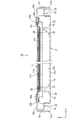
- FIG. 1 is an exploded perspective view showing a schematic configuration of a television receiver according to Embodiment 1 of the present invention.
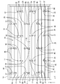
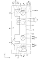
- Top view of the lamp clip Bottom view of lamp clip A plan view showing a state in which each lamp clip is attached to the chassis.
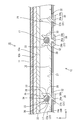
- Chassis top view Plan view with enlarged mounting holes in the chassis Sectional drawing which shows the attachment state of the lamp clip in a liquid crystal display device
- the top view which shows the state which match
- the top view which shows the state slid to attach the lamp clip made into the 1st state
- the top view which shows the state which each mounting part in the lamp clip made into the 2nd state became inconsistent with each corresponding mounting hole Xiv-xiv sectional view of FIG.
- the top view of the lamp clip which concerns on other embodiment (1) of this invention.
- the television receiver TV includes a liquid crystal display device 10, front and back cabinets Ca and Cb that are accommodated so as to sandwich the liquid crystal display device 10, a power source P, a tuner T, And a stand S.
- the liquid crystal display device (display device) 10 has a horizontally long rectangular shape (longitudinal shape) as a whole and is accommodated in a vertically placed state.
- the liquid crystal display device 10 includes a liquid crystal panel 11 that is a display panel and a backlight device (illumination device) 12 that is an external light source, which are integrated by a frame-like bezel 13 or the like.
- each drawing shows an X axis, a Y axis, and a Z axis, and each axis direction is drawn to be a direction shown in each drawing.
- the upper side shown in FIGS. 3 and 4 in the Z-axis direction is the front side, and the opposite lower side is the back side.
- the liquid crystal panel 11 and the backlight device 12 constituting the liquid crystal display device 10 will be described sequentially (see FIGS. 2 to 4).
- the liquid crystal panel (display panel) 11 is configured such that a pair of glass substrates are bonded together with a predetermined gap therebetween, and liquid crystal is sealed between the glass substrates.
- One glass substrate is provided with a switching element (for example, TFT) connected to a source wiring and a gate wiring orthogonal to each other, a pixel electrode connected to the switching element, an alignment film, and the like.
- the substrate is provided with a color filter and counter electrodes in which colored portions such as R (red), G (green), and B (blue) are arranged in a predetermined arrangement, and an alignment film.
- polarizing plates 11a and 11b are disposed outside both substrates (see FIGS. 3 and 4).
- the backlight device 12 is arranged so as to cover a substantially box-shaped chassis 14 opened on the light emitting side (front side, liquid crystal panel 11 side) and an opening 14 b of the chassis 14.
- a frame 16 held between the two a cold cathode tube (linear light source) 17, a lamp clip 18 for attaching the cold cathode tube 17 to the chassis 14, and electrical connection relay at each end of the cold cathode tube 17 are relayed.
- a relay connector 19 is provided, and a holder 20 that collectively covers the end of the cold cathode tube 17 group and the relay connector 19 group.
- the diffusion plate 15 a side is a light emission side from the cold cathode tube 17. 2 to 4, the illustration of the lamp clip 18 is omitted.
- the chassis 14 is made of metal and has a long bottom plate 14a and a folded outer edge portion 21 rising from each side thereof and folded back in a substantially U shape (folded outer edge portion 21a in the short side direction and folded outer edge portion in the long side direction). 21b) is formed into a shallow substantially box shape.
- the bottom plate 14a of the chassis 14 has a plurality of attachment holes 22 for attaching the relay connector 19 to both ends in the long side direction. Further, as shown in FIG. 3, a fixing hole 14c is formed in the upper surface of the folded outer edge portion 21b of the chassis 14, and the bezel 13, the frame 16, the chassis 14 and the like are integrated with, for example, screws. Is possible.
- a reflection sheet 23 is disposed on the inner surface side of the bottom plate 14a of the chassis 14 (the surface side facing the cold cathode tube 17).
- the reflection sheet 23 is made of synthetic resin, and the surface thereof is white with excellent reflectivity.
- the reflection sheet 23 is laid so as to cover almost the entire region along the inner side of the plate surface of the bottom plate 14 a of the chassis 14. As shown in FIG. 3, the long side edge portion of the reflection sheet 23 rises so as to cover the folded outer edge portion 21b of the chassis 14 and is sandwiched between the chassis 14 and the diffusion plate 15a. With this reflection sheet 23, the light emitted from the cold cathode tube 17 can be reflected toward the diffusion plate 15a.
- the cold cathode tube 17 is a kind of linear light source (tubular light source), and as shown in FIGS. 2 and 3, the chassis is in a posture in which the axial direction coincides with the long side direction (X-axis direction) of the chassis 14. 14 in a state in which a plurality of pieces are substantially parallel to each other and spaced apart from each other by a predetermined interval, that is, intermittently in the short side direction (Y-axis direction) of the chassis 14. It is arranged in parallel along.
- the interval between adjacent cold cathode tubes 17, that is, the arrangement pitch, is approximately equal.
- the cold cathode tube 17 is slightly lifted from the bottom plate 14 a (reflective sheet 23) of the chassis 14, and each end thereof is fitted into the relay connector 19 so as to cover the relay connector 19. A holder 20 is attached. In FIG. 4, the cold cathode tube 17 is not shown.
- the holder 20 is made of a white synthetic resin, covers an end portion of the cold cathode tube 17 and has a substantially elongated box shape extending along the short side direction of the chassis 14. As shown in FIG. 4, the holder 20 has a stepped surface on which the diffusion plate 15 a or the liquid crystal panel 11 can be placed in a stepwise manner, and is flush with the folded outer edge portion 21 a in the short side direction of the chassis 14. They are arranged so as to overlap each other, and form the side wall of the backlight device 12 together with the folded outer edge portion 21a.
- An insertion pin 24 protrudes from a surface of the holder 20 facing the folded outer edge portion 21a of the chassis 14, and the insertion pin 24 is inserted into an insertion hole 25 formed on the upper surface of the folded outer edge portion 21a of the chassis 14.
- the holder 20 is attached to the chassis 14.
- the stepped surface of the holder 20 is composed of three surfaces parallel to the surface of the bottom plate 14a of the chassis 14, and the short side edge of the diffusion plate 15a is placed on the first surface 20a at the lowest position. Furthermore, an inclined cover 26 that extends toward the inner surface of the bottom plate 14a of the chassis 14 extends from the first surface 20a. The short side edge portion of the liquid crystal panel 11 is placed on the second surface 20 b of the stepped surface of the holder 20. The third surface 20 c at the highest position among the stepped surfaces of the holder 20 is arranged at a position overlapping the folded outer edge portion 21 a of the chassis 14 and is in contact with the bezel 13.
- the diffusion plate 15a is formed by dispersing and mixing light scattering particles in a synthetic resin plate-like member, and has a function of diffusing substantially linear light emitted from the cold cathode tube 17 serving as a linear light source.
- the short side edge portion of the diffusion plate 15a is placed on the first surface 20a of the holder 20, and is not subjected to vertical restraining force.
- the long side edge portion of the diffusion plate 15a is fixed by being sandwiched between the chassis 14 (reflection sheet 23) and the frame 16, as shown in FIG.
- the optical sheet 15b disposed on the diffusion plate 15a is a laminate of a diffusion sheet, a lens sheet, and a reflective polarizing plate in order from the diffusion plate 15a side.
- the optical sheet 15b is emitted from the cold cathode tube 17 and passes through the diffusion plate 15a. It has a function of converting the light that has passed through into planar light.
- the liquid crystal panel 11 is installed on the upper surface side of the optical sheet 15 b, and the optical sheet 15 b is sandwiched between the diffusion plate 15 a and the liquid crystal panel 11. Note that the diffusion plate 15a and the optical sheet 15b, which are optical members, are both arranged in a longitudinal shape and the long side direction and the short side direction thereof coincide with the bottom plate 14a of the chassis 14 (FIG. 2).
- the lamp clip 18 is made of a synthetic resin (for example, made of polycarbonate) and has a white surface with excellent light reflectivity.
- the chassis 14 reflective sheet 23
- a substantially plate shape along the bottom plate 14a is formed, and a vertically long (longitudinal) main body portion 27 (mounting plate) is provided as viewed in a plane.
- the length direction (long side direction) of the main body 27 is substantially parallel to the Y-axis direction, that is, the short side direction of the chassis 14, and the width direction (short side) of the main body 27.
- the portion 27 is attached in a posture in which the width direction of the portion 27 is substantially parallel to the axial direction of the cold cathode tube 17.
- the lamp clips 18 are installed at a plurality of dispersed positions in the chassis 14, and the arrangement thereof will be described in detail below.
- Three lamp clips 18 on the bottom plate 14a of the chassis 14 are zigzag, three in the X axis direction (long side direction of the chassis 14) and six in the Y axis direction (short side direction of the chassis 14). They are arranged in a staggered pattern or staggered pattern.
- the three lamp clips 18 with respect to the X-axis direction are arranged linearly in parallel with a predetermined interval along the X-axis direction, so that the cold-cathode tubes 17 are separated at three positions in the axial direction. Can be gripped.
- the intervals between the three lamp clips 18 arranged in parallel in the X-axis direction are substantially equal.
- the three lamp clips 18 arranged in parallel in the X-axis direction form one row, and the lamp clips 18 included in each row adjacent in the Y-axis direction are arranged so as to be displaced from each other in the X-axis direction.
- Adjacent rows of lamp clips 18 are respectively arranged at approximately intermediate positions between the lamp clips 18 of a predetermined row.
- the lamp clip 18 is intermittently disposed in both directions of the X-axis direction and the Y-axis direction, so that the reflectance of the surface of the lamp clip 18 is different from the reflectance of the reflection sheet 23. Even if it is low, specifically, it is difficult for the lamp clip 18 to be visually recognized as a dark part, which is suitable for suppressing luminance unevenness.
- mounting holes 31 for inserting the mounting portions 30 described below at the respective mounting positions of the respective lamp clips 18 are provided on the inner surfaces of the chassis 14 and the bottom plates 14 a and 23 a of the reflection sheet 23.
- Three insertion holes 32 are formed penetrating in the thickness direction. The mounting portions 30, the mounting holes 31, and the insertion holes 32 will be described in detail later.
- two lamp gripping portions 28 are arranged adjacent to each other at positions separated from each other in the length direction (Y-axis direction) of the body portion 27.
- the tube 17 is gripped.
- the interval between two adjacent lamp gripping portions 28 substantially matches the arrangement pitch between the cold cathode tubes 17 arranged in the chassis 14.
- the two lamp gripping portions 28 are respectively arranged at a position closer to the center in the Y-axis direction and a position closer to one end (downward in FIG. 5) in the main body portion 27, both of which are center points BC of the main body portion 27. Is arranged at a position shifted in the Y-axis direction, that is, at an eccentric position.
- the lamp grip 28 near the center is relatively close to the center point BC of the main body 27, and the lamp grip 28 near the one end is relatively far from the center BC.
- the two lamp gripping portions 28 are arranged at substantially the same position in the X-axis direction, and the position is set to a substantially central position in the width direction (short side direction, X-axis direction) in the main body portion 27.
- one support pin 29 is arranged near the other end in the Y-axis direction in the main body 27, that is, near the end opposite to the lamp gripping portion 28 near one end (upward in FIG. 5). It is arranged at a position shifted from the center point BC of the portion 27 in the Y-axis direction, that is, an eccentric position.
- the support pin 29 is disposed at a position where the distance from the central point BC of the main body 27 to the lamp grip 28 near the one end is substantially equal to the distance from the central point BC. That is, it can be said that the support pins 29 and the lamp gripping portions 28 arranged near both ends of the main body portion 27 are arranged at positions that are point-symmetric with respect to the center point BC of the main body portion 27.
- the distance in the Y-axis direction between the support pin 29 and the lamp grip 28 near the center is narrower than the distance between adjacent lamp grips 28 (between the cold cathode tubes 17), specifically about half. It is considered a weak size.
- the arrangement of the support pins 29 in the X-axis direction is almost the same as that of the lamp grip portion 28. Accordingly, the two lamp gripping portions 28 and the support pins 29 are linearly arranged in parallel along the Y-axis direction with a predetermined interval therebetween.
- the lamp gripping portion 28 has an intermediate portion between both ends of the cold cathode tube 17 where the electrodes are installed, that is, a light emitting portion, from the back side to a height position slightly lifted from the reflection sheet 23. Can be supported.
- the lamp gripping portion 28 has an end-like annular shape that opens to the front as a whole, and includes a pair of arm portions 33 that face each other.
- An opening 34 that allows passage of the cold-cathode tube 17 that is attached and detached along the Z-axis direction (the thickness direction of the bottom plates 14 a and 23 a of the chassis 14 and the reflection sheet 23) is provided between the distal ends of both arm portions 33. It is secured.
- Both arm portions 33 have a cantilever shape that rises from a position separated in the length direction (Y-axis direction) on the front side surface of the main body portion 27, and has a shape curved in a substantially arc shape.
- the curvatures of both the arm portions 33 substantially coincide with the curvature of the outer peripheral surface of the cold cathode tube 17 to be attached, and the gap formed between the cold cathode tube 17 in the attached state has a substantially constant width in the circumferential direction.
- Both arm portions 33 have a symmetrical shape centering on a symmetrical axis along the Z-axis direction that passes through the center position in the Y-axis direction of the lamp gripping portion 28.
- Both arm portions 33 can be elastically deformed along the width direction with the rising base end portion from the body portion 27 as a fulcrum. Further, the width of the arm portion 33 is smaller than that of the main body portion 27.
- Holding projections 35 for holding the cold cathode tubes 17 are provided on the inner surfaces of the tip portions of both arm portions 33 (opposing circumferential surfaces facing the cold cathode tubes 17). Opened portion 34 is secured.
- the opening in the opening 34 is set to be slightly narrower than the outer diameter of the cold cathode tube 17. Therefore, when the cold cathode tube 17 is attached / detached through the opening 34, both arm portions 33 are elastically expanded and deformed by being pushed by the cold cathode tube 17.
- the holding projection 35 protrudes inwardly from the inner surface of the distal end portion of the arm portion 33 (toward the central axis side in the cold cathode tube 17), and the cold cathode tube 17 extends from the front side (light emitting side).
- the position is such that it is covered, that is, on the cold-cathode tube 17 on the side in the removal direction.
- the cold-cathode tube 17 has a first support point at the center located immediately below the center of the cold-cathode tube 17 on the bottom surface of the lamp gripping portion 28, a second support point at the inner ends of both holding projections 35, and A small gap extending in the circumferential direction between the outer peripheral surface of the cold cathode tube 17 and the inner peripheral surface of the lamp gripping portion 28 between the support points. (Clearance) is made available.
- the guide portions 36 for guiding the mounting operation of the cold cathode tubes 17 are provided on the outer surfaces of the distal ends of both arm portions 33, respectively. Both guide portions 36 are formed in a tapered shape that rises obliquely outward from the arm portion 33. Both guide portions 36 have a gradient that is spaced from the projecting base end to the projecting tip, and the inner surface that faces the cold cathode tube 17 is also an inclined surface having the same gradient. Therefore, the distance between the inner surfaces which are the opposing surfaces of the guide portions 36 is gradually narrower toward the lower side of the drawing, that is, toward the mounting direction side of the cold cathode tube 17, and conversely on the removal direction side of the cold cathode tube 17. It gradually gets wider as you go. Thereby, the mounting operation of the cold cathode tube 17 can be smoothly guided by the inner surfaces of the both guide portions 36. Further, the inner surface of the guide portion 36 is smoothly connected to the inner surface of the holding projection 35 as it is.
- the support pin 29 supports the center portion of the screen from the back side of the diffusion plate 15 a than the outer peripheral edge portion supported by the holder 20, so that the diffusion plate 15 a is on the cold cathode tube 17 side. It is possible to regulate bending and warping.
- the support pin 29 is formed in a tapered shape in which the cross-sectional shape cut along the horizontal direction is circular (FIG. 5), and the diameter gradually decreases from the root side to the tip side. That is, the support pin 29 is formed in a substantially conical shape. An R surface is formed and rounded at the tip of the support pin 29 that can come into contact with the diffusion plate 15a.
- the protrusion height of the support pin 29 from the main body 27 is set higher than that of the lamp gripping portion 28, and the support pin 29 is a portion protruding to the highest position in the lamp clip 18. Therefore, when performing the work of attaching / detaching the lamp clip 18 to / from the chassis 14, the operator can grasp the support pin 29 and perform the work, and the support pin 29 serves as an operation part at the time of attachment / detachment. Can also work.
- the lamp clip 18 is attached to the chassis 14 on the back surface (the surface facing the chassis 14 and the reflection sheet 23, the surface opposite to the diffusion plate 15 a and the cold cathode tube 17) of the main body 27.
- a total of three attachment portions 30 for holding are provided.
- each attachment portion 30 includes a base portion 30 a that protrudes from the back surface of the main body portion 27 toward the back side (chassis 14 side) along the Z-axis direction, and a tip portion of the base portion 30 a.
- the projection 30b protrudes in the X and Y axis directions (directions along the main body 27).
- the base 30a has a circular cross-sectional shape and a substantially constant diameter over its entire length, and is formed in a columnar shape.
- the protrusion 30b is formed in a flange shape (a bowl shape) that spreads radially from the distal end portion of the base portion 30a.
- the protrusion 30b is formed in a circular plate shape when seen in a plan view and has a diameter larger than that of the base 30a.
- the protrusion 30b is arranged concentrically with the base 30a.
- the mounting holes 31 provided in the chassis 14 are arranged at a large diameter portion 31a having a relatively large diameter and at a position spaced apart from the large diameter portion 31a by a predetermined distance.
- the small-diameter portion 31b having a relatively small diameter and the communicating portion 31c that communicates the large-diameter portion 31a and the small-diameter portion 31b.
- Both the large-diameter portion 31a and the small-diameter portion 31b are formed in a circular shape when viewed in plan.
- the communication part 31c that connects the large diameter part 31a and the small diameter part 31b has a straight shape with a constant width when seen in a plane.
- the large-diameter portion 31a is formed so that the diameter dimension thereof is larger than the diameter dimension of the protrusion 30b in the attachment portion 30, so that the protrusion 30b, that is, the attachment portion 30 can be inserted into the large-diameter portion 31a. It has become.
- the small-diameter portion 31b is formed so that its diameter dimension is larger than the diameter dimension of the base portion 30a in the mounting portion 30, but smaller than the diameter dimension of the protrusion 30b, and the protrusion 30b cannot be inserted. Is done.
- the large-diameter portion 31a and the small-diameter portion 31b are arranged side by side along the X-axis direction (the length direction of the cold cathode tube 17, the short side direction of the main body portion 27).
- the large-diameter portion 31a and the small-diameter portion 31b are arranged so that the line connecting the centers 31aC and 31bC is substantially parallel to the X-axis direction.
- the distance between the center 31aC of the large-diameter portion 31a and the center 31bC of the small-diameter portion 31b is substantially equal to the slide distance when the lamp clip 18 is attached.
- the small-diameter portion 31b is disposed at a position away from the large-diameter portion 31a by a predetermined distance forward (left side shown in FIG. 9, sliding direction when attached).
- the communication portion 31c is formed so as to be smaller than the diameter of the small diameter portion 31b, although the width of the communication portion 31c is larger than the diameter of the base portion 30a in the mounting portion 30. It is possible to move between the large-diameter portion 31a and the small-diameter portion 31b.
- the central position in the width direction of the communication portion 31c is arranged on a line connecting the center 31aC of the large diameter portion 31a and the center 31bC of the small diameter portion 31b.
- each insertion hole 32 formed in the reflection sheet 23 is arranged at a position overlapping with each mounting hole 31 when seen in a plane when the reflection sheet 23 is laid in the chassis 14. ing.
- Each insertion hole 32 has a rectangular shape that is horizontally long when viewed in a plane, the short side dimension is larger than the diameter dimension of the large diameter part 31a, and the long side dimension is each of the large diameter part 31a and the small diameter part 31b. It is still larger than the dimension obtained by adding the length dimension of the communication part 31c. That is, each insertion hole 32 is a size larger than each attachment hole 31.
- each mounting hole 31 and each insertion hole 32 is set to be equal to or larger than the assumed maximum value of the amount of misalignment that can occur between the reflection sheet 23 and the chassis 14 when assembled. ing. Thereby, each attachment hole 31 is reliably arranged inside each insertion hole 32, and the situation where each attachment hole 31 is covered with the reflective sheet 23 is avoided.
- Each attachment portion 30 and each attachment hole 31 are arranged in a positional relationship that can restrict the lamp clip 18 from being attached to the chassis 14 in a state different from a predetermined state. That is, when the lamp clip 18 is attached to the chassis 14, the main body portion 27 is aligned with the bottom plate 14 a of the chassis 14 and the long side direction of the main body portion 27 is aligned with the short side direction of the chassis 14. There are two states in which the main body 27 is rotated 180 degrees around a predetermined point. And, when the attachment portion 30 and the attachment hole 31 are attached in the first state (one state, the state shown in FIG.
- the lamp clip 18 is aligned with each other,
- the predetermined attachment part 30 is arranged so as to be inconsistent with the attachment hole 31 corresponding thereto.
- the three attachment portions 30 are intermittently juxtaposed along the Y-axis direction in the main body portion 27, and at a position closer to the center and closer to both ends in the Y-axis direction. Each of them is arranged, and both are arranged at a position shifted from the center point BC of the main body 27 in the Y-axis direction, that is, at an eccentric position.
- the two attachment portions 30 near both ends are arranged at both end portions in the length direction (long side direction) of the main body portion 27, and the positions at which the distances from the center point BC of the main body portion 27 are substantially equal. In other words, they are arranged at symmetrical positions.
- the mounting portion 30 near the center is located at a different distance from the mounting portions 30 near both ends, that is, relatively far from the mounting portion 30 near one end (the lower side shown in FIGS. 5 and 6), and the other end. It is arranged at a position that is relatively close to the mounting portion 30 on the side (upper side shown in FIGS. 5 and 6).
- the three attachment portions 30 are arranged at substantially the same position in the X-axis direction, and the position is substantially the center position in the width direction (short side direction, X-axis direction) in the main body portion 27. Then, the attachment portion 30 near the center and the attachment portion 30 near one end are arranged at positions that overlap with the two lamp gripping portions 28 arranged on the front side as seen in a plane.
- the attachment part 30 near the other end is arranged at a position that overlaps with and concentrics with the support pin 29 arranged on the front side in a plan view.
- the three mounting holes 31 are intermittently juxtaposed along the Y-axis direction in the bottom plate 14 a of the chassis 14, and the two mounting holes 31 near the both ends and the mounting near the center. The intervals between the holes 31 are different from each other.
- the mounting hole 31 near the center is disposed so as to be relatively close to the mounting hole 31 near the other end (upper side shown in FIG. 9).
- the three attachment portions 30 are arranged in the main body portion 27 so that two adjacent spaces in the Y-axis direction are two-way and asymmetric.
- the three attachment holes 31 are arranged in the bottom plate 14 a of the chassis 14 so that two adjacent spaces in the Y-axis direction are two-way and asymmetric. Accordingly, when the lamp clip 18 is in the first state and in the second state, the positions of the mounting portion 30 and the mounting hole 31 near the center are changed in the Y-axis direction. In the state 2, the mounting portion 30 and the mounting hole 31 near the center are not aligned with each other, and the insertion is restricted.
- the width dimension (dimension in the X-axis direction) in the main body 27 is the maximum outer diameter dimension (the large diameter part 31a and the small diameter part 31b) in each mounting hole 31, as shown in FIGS.
- the dimension obtained by adding each diameter dimension and the length dimension of the communication portion 31c) is smaller. For this reason, when the lamp clip 18 is attached, it is impossible to cover the entire area of each attachment hole 31 with the main body 27. Therefore, in this embodiment, a total of three projecting portions 37 that partially project from the main body portion 27 are provided in order to cover each attachment hole 31.
- the projecting portion 37 is disposed at a position corresponding to each of the three attachment portions 30 in the Y-axis direction at the rear end portion of the main body portion 27 and is opposite to the rear side from the main body portion 27, that is, the sliding direction at the time of attachment. It has a plate-like shape that protrudes from the top.
- the protrusion 37 has a protrusion dimension (dimension in the X-axis direction) from the main body 27 that is at least larger than the difference between the width of the main body 27 and the maximum outer diameter of each mounting hole 31. .
- the projecting dimension of the projecting part 37 from the main body part 27 is approximately the same as or larger than the sliding amount accompanying the attachment / detachment of the lamp clip 18.
- the projecting portion 37 has a width dimension (dimension in the Y-axis direction) larger than the diameter dimension of the large-diameter portion 31a in each mounting hole 31 and is equal to each other. Thereby, in the state which attached the lamp clip 18, each attachment hole 31 is obstruct
- FIG. The projecting dimensions of the projecting portions 37 from the main body portion 27 are substantially equal.
- each lamp clip 18 is arranged with respect to the chassis 14 as follows. That is, as shown in FIG. 7, the bottom plate 14 a in the chassis 14, that is, the attachment region of the lamp clip 18, is arranged along the long side direction (X-axis direction) and through the center with the reference line L passing through the center.
- the distance from the reference line L to each support pin 29 is relatively smaller than the distance from the reference line L to the center point BC of each main body 27.
- the first region A1 and the second region A2 that are adjacent to each other with the reference line L interposed therebetween are arranged so that the sliding directions at the time of attachment are reversed.
- the reference line L is assumed to pass along the center of the long side direction (X-axis direction) of the diffusion plate 15a and the optical sheet 15b, which are optical members.
- the lamp clip 18 arranged in the first area A1 has a main body 27 with a support pin 29 on the lower side, and the lamp arranged in the second area A2.
- the clips 18 are respectively attached to the bottom plate 14a of the chassis 14 so that the main body portion 27 has the support pins 29 on the upper side in the figure. That is, each of the lamp clips 18 has the other end of the main body 27 provided with the support pin 29 close to the reference line L and the one end provided with the lamp gripping portion 28 on the side opposite to the reference line L side.
- each support pin 29 eccentrically arranged in the Y-axis direction in each main body 27 are arranged near the reference line L. . Therefore, the support position of each support pin 29 with respect to the diffusion plate 15a is closer to the center side in the short side direction (Y-axis direction) of the diffusion plate 15a than when the support pins are arranged at the center of the main body 27. In other words, the distribution density of the support pins 29 becomes higher toward the center in the short side direction of the diffusion plate 15a.
- the structure tends to bend or warp more toward the cold cathode tube 17 side toward the center of the screen due to its structure. Since many are distributed, bending and curvature can be controlled well.
- the lamp clip 18 having the support pin 29 eccentrically arranged is arranged so that the support pin 29 is close to the reference line L1, whereby the deflection and warpage of the diffusion plate 15a can be well regulated. An effect is obtained.
- each lamp clip 18 (each lamp clip 18 made into the 1st state) attached to 1st area
- region A1 has each protrusion part 37 located in the left side shown in FIG.7 and FIG.12 with respect to the main-body part 27.
- each lamp clip 18 (each lamp clip 18 in the first state) attached to the second region A2 has each protrusion 37 on the right side shown in FIG. positioned.
- the lamp clip 18 attached to the first area A1 and the lamp clip 18 attached to the second area A2 have the same mounting structure, although the mounting posture with respect to the chassis 14 is inverted 180 degrees.
- the lamp clip 18 used in the backlight device 12 has only one type.
- the lamp clip 18 as a common part can be used, and the support pins 29 in the respective areas A1 and A2 can be used. Can be arranged at a position biased toward the reference line L.
- the kind of the lamp clip 18 is one kind, the manufacturing cost of the lamp clip 18 and the part management cost can be reduced, and the manufacturing cost of the backlight device 12 can be effectively reduced. it can.
- the support pin 29 in each lamp clip 18 is closest to the reference line L in comparison with the two lamp gripping portions 28, and conversely, the lamp gripping portion 28 on one end side is supported by the lamp gripping portion 28 on the center side and the support pin 29. In comparison with the pin 29, it is arranged farthest from the reference line L.
- the lamp clips 18 disposed in the respective regions A1 and A2 adjacent to each other with the reference line L interposed therebetween include those having a substantially equal distance from the reference line L to the support pin 29. Specifically, among the rows of the lamp clips 18 that are arranged in parallel in the X-axis direction in the chassis 14, each lamp clip 18 that forms the row closest to the reference line L in the first region A1 and the second region A2. The distances in the Y-axis direction from the reference line L are substantially equal to each lamp clip 18 that forms a row closest to the reference line L in FIG.
- each lamp clip 18 that forms the second closest row from the reference line L and each lamp clip 18 that forms the farthest row from the reference line L are also in the same positional relationship as described above and overlap. Description is omitted. Accordingly, there are six rows of lamp clips 18 arranged in parallel in the X-axis direction along the Y-axis direction, whereas there are three types of distances from the lamp clips 18 included in each row to the reference line L. That is, it is half the total number of rows. Furthermore, the lamp clips 18 arranged in the areas A1 and A2 are arranged so as to be substantially point-symmetric with respect to the center point SC of the bottom plate 14a of the chassis 14.
- the arrangement of the mounting holes 31 for mounting the lamp clips 18 arranged as described above will be described in detail.
- three mounting holes 31 are arranged in one set for each scheduled mounting position of each lamp clip 18, and the three mounting holes 31 constituting this one set are the reference holes.
- the distance in the Y-axis direction between the line closest to the line L and the line closest to the second is relatively narrow, and the line Y closest to the line L and the line farthest from the reference line L
- the arrangement is such that the spacing in the axial direction is relatively wide.
- the above-described arrangement of the three attachment holes 31 forming one set is the same in the first region A1 and the second region A2 across the reference line L.
- the mounting portions 30 are aligned with the mounting holes 31 and are allowed to be mounted. Further, the mounting holes 31 arranged in the regions A1 and A2 are arranged so as to be substantially point-symmetric with respect to the center point SC of the bottom plate 14a of the chassis 14.
- each attachment hole 31 arranged in the first region A1 has a large-diameter portion 31a, a communication portion 31c, and a small-diameter portion 31b lined up toward the right side shown in FIGS.
- Each attachment hole 31 arranged in A2 has a large-diameter portion 31a, a communication portion 31c, and a small-diameter portion 31b arranged in the left direction shown in FIGS.
- each lamp clip 18 attached to the first area A1 has a sliding direction when attached to the chassis 14 is the direction of the arrow X1 shown in FIG. 11 (the right side shown in FIG. 11), whereas the second area A2
- Each of the lamp clips 18 attached to the chassis 14 has a sliding direction when attached to the chassis 14 in the direction of the arrow X2 shown in FIG. 11 (left side shown in FIG. 11), that is, the direction opposite to the direction of the arrow X1.
- the sliding direction when the lamp clip 18 is removed from the chassis 14 is also reversed in each of the areas A1 and A2.
- This embodiment has the structure as described above, and its operation will be described next.
- the liquid crystal panel 11 and the backlight device 12 are separately manufactured and assembled to each other using the bezel 13 or the like, whereby the liquid crystal display device 10 shown in FIGS. 3 and 4 is manufactured.
- the assembly work of the backlight device 12, particularly the work of attaching the lamp clip 18 to the chassis 14 will be described in detail.
- the corresponding attachment holes 31 face each other in the respective insertion holes 32, so that the lamp clips 18 are subsequently attached to the chassis 14.
- this attachment work is divided between the worker in charge of attaching the chassis 14 to the first area A1 and the worker in charge of attachment to the second area A2. Is preferred. That is, the workers in charge of the areas A1 and A2 are arranged at positions where the chassis 14 is sandwiched in the Y-axis direction, and each worker is told that “the lamp clip 18 has the support pin 29 on the back side.
- the work efficiency can be improved.
- the liquid crystal display device 10 is large, the short side dimension of the chassis 14 is large. Therefore, compared to a case where one lamp is attached to one worker from one side in the short side direction. The working efficiency can be remarkably increased, which is preferable. The same effect as described above can be obtained when the lamp clip 18 is removed from the chassis 14.
- each attachment portion 30 is attached to the chassis 14.
- the lamp clip 18 is inserted into each mounting hole 31 at the planned position.
- the lamp clip 18 is centered on the center point BC of the main body 27 from the first state in which the projections 37 face rearward. It can be in any state of the second state in which the projections 37 are rotated 180 degrees and the protrusions 37 face forward.
- each attachment part 30 and each attachment hole 31 are arranged so that attachment of the lamp clip 18 is permitted only in the first state. First, the case where the lamp clip 18 is in the first state will be described.
- each mounting portion 30 is aligned with each mounting hole 31. Accordingly, when the lamp clip 18 is pushed into the chassis 14 in this state, the protrusions 30b of the attachment portions 30 are inserted into the large diameter portions 31a of the attachment holes 31, respectively, as shown in FIG. At this time, each attachment portion 30 is concentric with the large diameter portion 31 a of each attachment hole 31. In this operation, the support pin 29 operated by the operator and the mounting portion 30 on the other end side of the main body portion 27 are superimposed on each other in a plan view and are concentrically arranged. . At this time, each attachment hole 31 is covered with the main body portion 27 with respect to the large diameter portion 31a, while being exposed with respect to the small diameter portion 31b.
- the lamp clip 18 is slid forward along the X-axis direction.
- the lamp clip 18 attached to the first region A1 is directed in the direction (right side) of the arrow X1 shown in FIG. 11, and the lamp clip 18 attached to the second region A2 is shown by the arrow X2 shown in FIG. Slide in the direction of (left side).
- the base portion 30a enters the small diameter portion 31b from the large diameter portion 31a through the communication portion 31c, and the projection 30b is arranged opposite to the back side with respect to the hole edge of the mounting hole 31 in the chassis 14. .
- the attachment portion 30 When the lamp clip 18 is moved to the normal position, as shown in FIG. 12, the attachment portion 30 is arranged concentrically with the small diameter portion 31b. At this time, as shown in FIG. 10, the hole edge of the attachment hole 31 (particularly the hole edge of the small diameter part 31 b and the communication part 31 c) is sandwiched between the protrusion 30 b of the attachment part 30 and the main body part 27. Thereby, the lamp clip 18 is held in an attached state with respect to the chassis 14 and the reflection sheet 23. In this attached state, as shown in FIG. 12, the attachment holes 31 and the insertion holes 32 are closed over the entire area by the main body 27 and the protrusions 37 of the lamp clip 18 and are opened in the chassis 14 (opening). To prevent exposure). Further, in the mounted state, since the hole edge of the mounting hole 31 is held by the flange-shaped protrusion 30b in the mounting portion 30, a sufficient holding area can be secured and a high holding force can be obtained.
- FIG. 13 shows a case where the lamp clip 18 is in the second state in the second region A2.
- the attachment portion 30 on the center side interferes with the bottom plate 14 a of the chassis 14, so that the lamp clip 18 in the second state is restricted from being attached to the chassis 14. The In that case, the operator changes the lamp clip 18 to the first state and then performs the mounting operation again.
- the attachment of the lamp clip 18 in a second state where the attachment hole 31 is not blocked is restricted, and the attachment hole 31 is blocked in the first state. Since only the lamp clip 18 is allowed to be mounted, all the mounting holes 31 can be reliably closed by the lamp clip 18, thereby reliably preventing a dark portion or light leakage from occurring in the liquid crystal panel 11. Can do.
- each lamp clip 18 When each lamp clip 18 is attached to the chassis 14 in the first state as described above, an operation of attaching each cold cathode tube 17 to each lamp gripping portion 28 while accommodating it in the chassis 14 is performed.
- the slide direction of the lamp clip 18 is the same as the X-axis direction, that is, the axial direction of the cold cathode tube 17. Therefore, the position of each lamp gripper 28 in the Y-axis direction is prevented from changing.
- the liquid crystal panel 11 is further mounted from the front side, and then the bezel 13 is assembled, as shown in FIGS.
- the liquid crystal display device 10 is assembled.
- the diffusion plate 15a and each optical sheet 15b which are optical members, are assembled to the chassis 14, the diffusion plate 15a disposed on the back side is supported from the back side by the support pins 29 of the lamp clips 18, as shown in FIG.
- the positional relationship between the diffusion plate 15a and the cold cathode tube 17 in the Z-axis direction is kept constant.
- the diffusion plate 15a and the optical sheet 15b may undergo thermal expansion or thermal contraction when the temperature environment in the backlight device 12 changes as the cold cathode tube 17 is turned on or off. Deflection and warpage associated with heat shrinkage tend to occur intensively on the center side.
- each lamp clip 18 has a distance from the reference line L to the support pin 29 rather than a distance from the reference line L to the center point BC in the main body 27 as shown in FIG.
- the distribution density of the support pins 29 in the plane of the diffuser plate 15a is increased toward the reference line L, that is, the center side in the short side direction (Y-axis direction).
- the central portion of the diffuser plate 15a that is likely to be bent or warped can be favorably supported by the support pins 29.
- unevenness in luminance is less likely to occur in the emitted light of the backlight device 12 emitted through the diffusion plate 15a and the optical sheet 15b.
- the backlight device 12 of the present embodiment includes the chassis 14 provided with the mounting holes 31 opened, the cold cathode tube 17 that is a linear light source housed in the chassis 14, and the cold cathode tube 17.
- a diffuser plate 15a which is an optical member disposed on the light emitting side, a main body portion 27 attached to the chassis 14, a lamp grip portion 28 provided on the main body portion 27 and capable of gripping the cold cathode tube 17, and a main body portion 27 is disposed at an eccentric position and can support the diffusion plate 15 a, and protrudes from the main body 27 toward the chassis 14 and is inserted into the mounting hole 31 and between the main body 27 and the mounting hole 31.
- a plurality of lamp clips 18 that slide along the reference line L, and the plurality of lamp clips 18 are more than the distance from the reference line L that divides the installation area of the lamp clip 18 in the chassis 14 to the center of the main body 27.
- the distance from L to the support pin 29 is relatively small, and the sliding direction at the time of attachment is arranged to be opposite to each other in the adjacent areas A1 and A2 across the reference line L.
- the cold cathode tube 17 housed in the chassis 14 is gripped by the lamp gripping portion 28 of the lamp clip 18, while the diffusion plate 15a disposed on the light emitting side of the cold cathode tube 17 is: It is supported by the support pins 29 of the lamp clip 18.
- the plurality of lamp clips 18 attached to the chassis 14 have a distance from the reference line L that divides the installation area of the lamp clips 18 in the chassis 14 to the support pins 29 arranged at eccentric positions in the main body 27. Since it is arranged so as to be relatively smaller than the distance from the reference line L to the center of the main body 27, the distribution density of the support pins 29 in the plane of the diffusion plate 15a tends to increase toward the reference line L side. Become.
- the diffusion plate 15a can be favorably supported by the support pins 29 to prevent the occurrence of bending or warping. It can. Thereby, luminance unevenness hardly occurs in the light emitted from the backlight device 12.
- the slide direction when the lamp clip 18 is attached to and detached from the chassis 14 is along the axial direction of the cold cathode tube 17, for example, the amount of slide of the lamp clip 18 is excessive or insufficient at the time of attachment. Even if there is, a change in the positional relationship between the lamp gripping portion 28 and the cold cathode tube 17 in the direction crossing the axial direction of the cold cathode tube 17 can be avoided. Therefore, when the cold cathode tube 17 is gripped by the lamp gripping portion 28, an excessive force is prevented from acting on the cold cathode tube 17, and the cold cathode tube 17 can be stably held.
- the support pins 29 are attached to the main body 27. It is possible to attach the same parts as the lamp clip 18 having a configuration in which the two are decentered to the adjacent regions A1 and A2 with the reference line L in between. Thereby, the number of types of the lamp clips 18 can be reduced, and the cost can be reduced.
- the work of attaching the areas A ⁇ b> 1 and A ⁇ b> 2 in the chassis 14 with the reference line L as a boundary is assigned to different workers. Since it is possible to share the work instruction content to the work, it is possible to improve workability.
- the reference line L passes through the center of the diffusion plate 15a.
- the support pins 29 in the lamp clip 18 are arranged so that the distribution density in the plane of the diffusion plate 15a becomes higher toward the reference line L side.
- the central portion where there is a concern about this can be appropriately supported by the support pins 29.
- the diffusion plate 15a has a longitudinal shape, and the reference line L is along the long side direction of the diffusion plate 15a.
- the support pins 29 in the lamp clip 18 are arranged so that the distribution density in the plane of the diffusion plate 15a becomes higher toward the reference line L side.
- the support pins 29 can be appropriately supported.
- the support pin 29 is arranged closer to the reference line L than the lamp gripping portion 28 in the main body portion 27. In this way, the diffusion plate 15a can be supported by the lamp gripping portion 28 and the support pin 29 positioned closer to the reference line L than the cold cathode tube 17 gripped by the lamp gripping portion 28, so that the diffusion plate 15a is bent or warped. Etc. can be prevented more suitably.
- the support pin 29 is disposed on the end portion of the main body portion 27 near the reference line L. In this way, since the diffusion plate 15a can be supported by the support pin 29 arranged closest to the reference line L in the lamp clip 18, it is possible to more suitably prevent deformation such as bending and warping of the diffusion plate 15a. it can.
- the lamp clips 18 disposed in the regions A1 and A2 adjacent to each other with the reference line L in the chassis 14 include those in which the distance from the reference line L to the support pin 29 is substantially equal. In this way, the diffusion plate 15a can be more appropriately supported by the support pins 29.
- the mounting hole 31 includes a large-diameter portion 31a having a relatively large diameter, a small-diameter portion 31b having a relatively small diameter, and a communication portion 31c that connects the large-diameter portion 31a and the small-diameter portion 31b.
- the hole edge of the small diameter portion 31b can be clamped between the mounting portion 30 and the main body portion 27. In this way, when the attachment portion 30 is inserted into the large diameter portion 31a in the attachment hole 31 and then the lamp clip 18 is slid, the attachment portion 30 enters the small diameter portion 31b through the communication portion 31c and is attached.
- the hole edge of the small diameter portion 31 b is sandwiched between the portion 30 and the main body portion 27. Thereby, the lamp clip 18 can be stably held in the attached state with respect to the chassis 14.
- the mounting holes 31 are arranged so that the arrangement order of the large diameter portion 31a and the small diameter portion 31b is reversed in the regions A1 and A2 adjacent to each other with the reference line L interposed therebetween. In this way, when attaching the lamp clip 18 to the chassis 14, the sliding direction can be reversed in the adjacent areas A ⁇ b> 1 and A ⁇ b> 2 across the reference line L.
- the main body 27 protrudes in the direction opposite to the sliding direction when the lamp clip 18 is attached, and at least a part of the main body 27 is a large-diameter portion when viewed in plan when the attachment portion 30 enters the small-diameter portion 31b.
- a protruding portion 37 that overlaps 31a is provided. In this way, when the lamp clip 18 is slid after the attachment portion 30 is inserted into the large diameter portion 31 a, the attachment portion 30 enters the small diameter portion 31 b and enters the small diameter portion 31 b between the main body portion 27 and the main body portion 27. And at least a part of the protruding portion 37 overlaps with the large-diameter portion 31a in a plan view.
- the protrusion part 37 is a form which protrudes partially from the main-body part 27, compared with the case where the main-body part 27 is made wide over the full length, the surface area of the lamp clip 18 can be made small and it is suitable for brightness nonuniformity prevention. It is also suitable for reducing material costs.
- the protruding portion 37 is formed wider than the large diameter portion 31a. If it does in this way, it will become possible to cover the large diameter part 31a over the whole area by the protrusion part 37.
- At least three attachment portions 30 and three attachment holes 31 are provided in parallel and intermittently in the direction substantially orthogonal to the axial direction of the cold-cathode tube 17, and at least two intervals between adjacent ones are provided. And are arranged so as to be asymmetric. In this way, when the lamp clips 18 are to be attached to the chassis 14 in a state different from the predetermined state, at least three of them are intermittently arranged in parallel in the direction substantially perpendicular to the axial direction of the cold cathode tubes 17. Since the mounting portions 30 and the mounting holes 31 that are respectively provided so as to be asymmetrical with each other are provided with at least two intervals between the adjacent ones and the mounting holes 31 are not aligned with each other. The operator can see that the lamp clip 18 was different from the predetermined state. In this case, the worker sets the lamp clip 18 in a predetermined state and then performs the mounting work again.
- the at least three mounting portions 30 and the mounting holes 31 are arranged at substantially the same position in the axial direction of the cold cathode tube 17. In this way, the lamp clip 18 can be kept small in the axial direction of the cold cathode tube 17.
- the two attachment portions 30 arranged on both ends of the main body portion 27 are arranged at positions where the distances from the center point BC in the main body portion 27 are substantially equal. Since the lamp clip 18 is held in the attached state with respect to the chassis 14 by sandwiching the hole edge of the attachment hole 31 between the main body part 27 and the attachment part 30, the lamp clip 18 is arranged on both ends of the main body part 27. By arranging the two attachment portions 30 as described above, the lamp clip 18 can be stably held with respect to the chassis 14.
- the mounting portion 30 includes a portion arranged so as to overlap the support pin 29 in a plan view. In this way, when inserting the attachment portion 30 into the corresponding attachment hole 31, the support pin 29 arranged at a position overlapping with the attachment portion 30 can be operated, so that the workability related to the insertion is improved. Can be made.
- the mounting portion 30 includes a portion arranged so as to be concentric with the support pin 29. In this way, when inserting the attachment portion 30 into the corresponding attachment hole 31, the support pin 29 disposed at a position concentric with the attachment portion 30 can be operated. Can be improved.
- the mounting portion 30 includes a portion arranged so as to overlap the lamp grip portion 28 in a plan view. In this way, the position of the lamp gripping portion 28 can be easily grasped by visually observing the mounting portion 30. On the contrary, the position of the attachment portion 30 can be easily grasped by visually observing the lamp grip portion 28.
- a plurality of the cold cathode tubes 17 are arranged intermittently in parallel with their axial directions parallel to each other, whereas the lamp gripping portion 28 and the support pin 29 are adjacent to each other and spaced from each other. They are arranged so as to be narrower than the interval between adjacent cold cathode tubes 17. In this way, the support pins 29 can be arranged between the adjacent cold cathode tubes 17. Further, if the distance between the lamp gripping portion 28 and the support pin 29 is made wider than the distance between adjacent cold cathode tubes 17, the lamp clip 18 can be made smaller in the parallel direction of the cold cathode tubes 17. Can keep.
- the support pin 29 is adjacent to the lamp gripping portion 28 and the distance between the lamp gripping portions 28 is adjacent to the lamp gripping portion. It arrange
- the plurality of lamp gripping portions 28 are arranged at substantially the same position in the axial direction of the cold cathode tube 17. In this way, the holding positions of the lamp holding portions 28 with respect to the cold cathode tubes 17 are substantially the same in the axial direction, so that the cold cathode tubes 17 can be stably held.
- the lamp gripping portion 28 and the support pin 29 are arranged at substantially the same position in the axial direction of the cold cathode tube 17. In this way, the lamp clip 18 can be kept small in the axial direction of the cold cathode tube 17.
- those disposed on both ends of the main body portion 27 are disposed at positions where the distance from the center of the main body portion 27 is substantially equal. In this way, the function of the lamp gripping portion 28 or the support pin 29 arranged on both ends in the main body portion 27 can be appropriately exhibited.
- a plurality of cold cathode tubes 17 are arranged in parallel at substantially equal intervals while their axial directions are parallel to each other. In this way, luminance unevenness is less likely to occur in the emitted light from the backlight device 12.
- the plurality of lamp clips 18 are arranged in a zigzag manner in the chassis 14. This makes it difficult for the lamp clip 18 disposed in the chassis 14 to be visually recognized as a dark part, and is suitable for preventing luminance unevenness.
- the linear light source is composed of a cold cathode tube 17. By doing so, it is possible to extend the life and to easily perform light control.
- the present invention is not limited to the embodiments described with reference to the above description and drawings.
- the following embodiments are also included in the technical scope of the present invention.
- the arrangement of the lamp gripping portion and the support pins can be changed as appropriate. Specifically, for example, as shown in FIG. 15, two lamp gripping portions 28 ′ are arranged at both ends of the main body portion 27 ′, whereas a support pin 29 ′ is arranged at the center side.
- the present invention also includes a configuration in which the support pin 29 'is arranged at a position eccentric in the Y-axis direction in the main body 27', that is, at a position shifted from the center point BC 'toward one lamp gripping portion 28'. Even in this case, it is preferable that the mounting portions 30 'are arranged at positions where they overlap with the lamp gripping portions 28' and the support pins 29 'in plan view.
- the sliding direction when the lamp clip 18 arranged in the first area A1 is attached is on the right side shown in FIG. 7, and the sliding direction when the lamp clip 18 arranged in the second area A2 is attached.
- the left side shown in FIG. 7 it is of course possible to set the left and right directions in reverse directions. In that case, it is necessary to reverse the order of arrangement of the large-diameter portion and the small-diameter portion with respect to the mounting holes arranged in each region, as shown in FIG.
- the reference line L overlaps with the main body portion 27 of the nearest lamp clip 18, but the lamp clip 18 with the nearest reference line is illustrated. Of course, it is possible to arrange them so as not to overlap with each other.
- the reference line is set along the long side direction (X-axis direction) in the chassis and the diffusion plate and passes through the center position in the short side direction.
- the position of the line can be changed.
- the reference line may be set to pass through a position (an eccentric position) that is offset from the center position in the short side direction of the chassis and the diffusion plate.
- the direction of the reference line can be changed.
- the axial direction of the cold-cathode tube and the short-side direction of the chassis and the diffusion plate may be aligned, and the reference line may be set along the short-side direction of the chassis and the diffusion plate.
- the number of types of distance from the lamp clip included in each row to the reference line is smaller than the number of rows of the lamp clips arranged in parallel in the X-axis direction.
- the lamp clips arranged in the respective regions are arranged so as to be substantially point-symmetric with respect to the center point of the bottom plate of the chassis. Of course, it is also possible to arrange them asymmetrically.
- the attachment portion and the attachment hole are linearly arranged along the Y-axis direction.
- the attachment portion and the attachment hole are at two or more different positions in the X-axis direction. What was arranged is also included in the present invention.
- the large-diameter portion and the small-diameter portion constituting each mounting hole are arranged apart from each other in the axial direction (X-axis direction) of the cold cathode tube, that is, the large-diameter portion and the small-diameter portion.
- the distance between the center and the diameter of the large-diameter portion and the diameter of the small-diameter portion are larger than the sum of the diameters of the large-diameter portion and the small-diameter portion.
- the positional relationship can be changed as appropriate.
- the present invention includes a case where the distance between the centers of the large diameter portion and the small diameter portion is substantially the same as or smaller than the sum of the diameter dimensions of the large diameter portion and the small diameter portion. It is. Among these, when the said distance becomes small, a large diameter part and a small diameter part will overlap partially seeing on a plane.
- the attachment portion and the lamp gripping portion are arranged so as to overlap each other when viewed in a plane. included.
- the mounting portion and the support pin are concentrically arranged so as to overlap in plan view.
- the center of the mounting portion and the center of the support pin are misaligned.
- they can be arranged so as to overlap each other when seen in a plane.
- the cold cathode tube is used as the linear light source.
- other types of linear light sources such as a hot cathode tube may be used.
- the liquid crystal panel and the chassis are illustrated in a vertically placed state in which the short side direction coincides with the vertical direction.
- the liquid crystal panel and the chassis have the long side direction as the vertical direction. What is set to the vertically placed state matched is also included in the present invention.
- the TFT is used as the switching element of the liquid crystal display device.
- the present invention can also be applied to a liquid crystal display device using a switching element other than TFT (for example, a thin film diode (TFD)), and color display.
- a switching element other than TFT for example, a thin film diode (TFD)
- color display for example, a liquid crystal display device
- the present invention can be applied to a liquid crystal display device that displays black and white.
- liquid crystal display device using the liquid crystal panel as the display panel is illustrated, but the present invention can be applied to a display device using another type of display panel.
- the television receiver provided with the tuner is exemplified.
- the present invention can also be applied to a display device that does not include the tuner.
- the diffusing plate is exemplified as the optical member directly supported by the support pin.
- other types of optical members such as a diffusion sheet
- the diffusion sheet, the lens sheet, and the reflective polarizing plate, which are optical sheets are illustrated as the optical members indirectly supported by the support pins
- other types of optical sheets such as lenticular lens sheets
- the number of optical sheets used can be changed as appropriate.
- SYMBOLS 10 Liquid crystal display device (display device), 11 ... Liquid crystal panel (display panel), 12 ... Backlight device (illumination device), 14 ... Chassis, 15a ... Diffusing plate (optical member), 15b ... Optical sheet (optical member) , 17 ... Cold cathode tube (linear light source), 18 ... Lamp clip (light source holder), 27 ... Main body part, 28 ... Lamp grip part (light source grip part), 29 ... Support pin (support part), 30 ... Installation Part (attachment part), 31 ... attachment hole (attachment hole), 31a ... large diameter part, 31b ... small diameter part, 31c ... communication part, 37 ... projection part, A1 ... first area (area), A2 ... second area (Area), BC ... center point (center), L ... reference line, TV ... TV receiver
Landscapes
- Physics & Mathematics (AREA)
- Nonlinear Science (AREA)
- Mathematical Physics (AREA)
- Chemical & Material Sciences (AREA)
- Crystallography & Structural Chemistry (AREA)
- General Physics & Mathematics (AREA)
- Optics & Photonics (AREA)
- Engineering & Computer Science (AREA)
- Multimedia (AREA)
- Signal Processing (AREA)
- Planar Illumination Modules (AREA)
Abstract
本発明に係るバックライト装置12は、取付孔31が設けられるシャーシ14と、冷陰極管17と、拡散板15aと、シャーシ14に取り付けられる本体部27と、冷陰極管17を把持可能なランプ把持部28と、本体部27における偏心した位置に配されるとともに拡散板15aを支持可能な支持ピン29と、取付孔31内に挿入されるとともに本体部27との間で取付孔31の孔縁を挟持可能な取付部30とを備えるものであって、シャーシ14に対する着脱に際して冷陰極管17の軸線方向に沿ってスライドされる複数のランプクリップ18とを備え、複数のランプクリップ18は、基準線Lから本体部27における中心までの距離よりも、基準線Lから支持ピン29までの距離の方が相対的に小さくなり、且つ取り付け時のスライド方向が基準線Lを挟んで隣り合う領域A1,A2で互いに逆になるよう配されている。
Description
本発明は、照明装置、表示装置、及びテレビ受信装置に関する。
例えば、液晶テレビなどの液晶表示装置に用いる液晶パネルは、自発光しないため、別途に照明装置としてバックライト装置を必要としている。このバックライト装置は、液晶パネルの裏側(表示面とは反対側)に設置されるようになっており、金属製や樹脂製で液晶パネル側の面が開口したシャーシと、ランプとしてシャーシ内に収容される多数本の蛍光管(例えば冷陰極管)と、シャーシの開口部分に配されて冷陰極管が発する光を効率的に液晶パネル側へ放出させるための多数枚の光学部材(拡散シート等)と、細長い管状をなす冷陰極管の中間部分を支持するためのランプクリップとを備える。
光学部材は、その外周縁部がシャーシに形成された受け面によって裏側から支持されるのに対し、画面中央側部分がランプクリップに形成された支持ピンによって裏側から支持される。一方、光学部材における外周縁部の表側には、液晶パネルを裏側から支持するためのフレームが被せられた状態で配される。このような構成の液晶表示装置の一例として例えば下記特許文献1に記載されたものが知られている。
(発明が解決しようとする課題)
ところで、上記した液晶表示装置においては、光学部材の外周縁部がシャーシの受け面とフレームとの間に挟まれることになるが、その外周縁部を挟圧状態に拘束すると、光学部材が熱膨張または熱収縮したときに外周縁部が変位不能となるため、光学部材の画面中央側部分に撓みや反りが集中的に発生するおそれがある。すると、バックライト装置からの出射光に輝度ムラが生じる可能性があった。
ところで、上記した液晶表示装置においては、光学部材の外周縁部がシャーシの受け面とフレームとの間に挟まれることになるが、その外周縁部を挟圧状態に拘束すると、光学部材が熱膨張または熱収縮したときに外周縁部が変位不能となるため、光学部材の画面中央側部分に撓みや反りが集中的に発生するおそれがある。すると、バックライト装置からの出射光に輝度ムラが生じる可能性があった。
本発明は上記のような事情に基づいて完成されたものであって、輝度ムラの発生を防ぐことを目的とする。
(課題を解決するための手段)
本発明の照明装置は、取付孔が開口して設けられるシャーシと、前記シャーシ内に収容される線状光源と、前記線状光源の光出射側に配される光学部材と、前記シャーシに取り付けられる本体部と、前記本体部に設けられるとともに前記線状光源を把持可能な光源把持部と、前記本体部における偏心した位置に配されるとともに前記光学部材を支持可能な支持部と、前記本体部から前記シャーシ側へ突出し前記取付孔内に挿入されるとともに前記本体部との間で前記取付孔の孔縁を挟持可能な取付部とを備えるものであって、前記シャーシに対する着脱に際して前記取付部を前記取付孔内に挿入した状態で前記線状光源の軸線方向に沿ってスライドされる複数の光源保持具とを備え、複数の前記光源保持具は、前記シャーシにおける前記光源保持具の設置領域を区分する基準線から前記本体部における中心までの距離よりも、前記基準線から前記支持部までの距離の方が相対的に小さくなり、且つ取り付け時のスライド方向が前記基準線を挟んで隣り合う領域で互いに逆になるよう配されている。
本発明の照明装置は、取付孔が開口して設けられるシャーシと、前記シャーシ内に収容される線状光源と、前記線状光源の光出射側に配される光学部材と、前記シャーシに取り付けられる本体部と、前記本体部に設けられるとともに前記線状光源を把持可能な光源把持部と、前記本体部における偏心した位置に配されるとともに前記光学部材を支持可能な支持部と、前記本体部から前記シャーシ側へ突出し前記取付孔内に挿入されるとともに前記本体部との間で前記取付孔の孔縁を挟持可能な取付部とを備えるものであって、前記シャーシに対する着脱に際して前記取付部を前記取付孔内に挿入した状態で前記線状光源の軸線方向に沿ってスライドされる複数の光源保持具とを備え、複数の前記光源保持具は、前記シャーシにおける前記光源保持具の設置領域を区分する基準線から前記本体部における中心までの距離よりも、前記基準線から前記支持部までの距離の方が相対的に小さくなり、且つ取り付け時のスライド方向が前記基準線を挟んで隣り合う領域で互いに逆になるよう配されている。
このようにすれば、シャーシ内に収容される線状光源は、光源保持具の光源把持部によって把持される一方、線状光源の光出射側に配される光学部材は、光源保持具の支持部によって支持される。ここで、シャーシに取り付けられる複数の光源保持具は、シャーシにおける光源保持具の設置領域を区分する基準線から本体部において偏心した位置に配された支持部までの距離が、基準線から本体部における中心までの距離よりも相対的に小さくなるよう配されているから、光学部材の面内における各支持部の分布密度が基準線側ほど高くなる傾向となる。そして、この基準線を光学部材における撓みや反りの発生が懸念される位置に設定することで、光学部材を各支持部によって良好に支持して撓みや反りの発生を防ぐことができる。これにより、当該照明装置からの出射光に輝度ムラが生じ難いものとされる。
しかも、本発明では、光源保持具をシャーシに着脱する際のスライド方向が線状光源の軸線方向に沿うものとされているから、例えば取り付け時において光源保持具のスライド量に過不足があった場合でも、線状光源の軸線方向と交差する方向について光源把持部と線状光源との位置関係に変化が生じることが避けられる。従って、光源把持部に線状光源を把持させたときに、線状光源に無理な力が作用することが防がれ、もって線状光源を安定的に保持することができる。その上で、複数の光源保持具は、シャーシに対する取り付け時のスライド方向が基準線を挟んで隣り合う領域で互いに逆になるよう配されるから、本体部に支持部を偏心して配した構成の光源保持具として同一部品を、基準線を挟んで隣り合う領域にそれぞれ取り付けることが可能となる。これにより、光源保持具の品種数を削減でき、低コスト化などを図ることができる。それ以外にも、例えば光源保持具をシャーシに取り付ける作業を行うにあたり、基準線を境にしてシャーシ内の各領域に対する取付作業を異なる作業者に分担させるとともに、各作業者への作業指示内容を共通化させることが可能とされるので、作業性の向上を図ることができる。
本発明の実施態様として、次の構成が好ましい。
(1)前記基準線は、前記光学部材における中央を通るものとされる。このようにすれば、光源保持具における支持部は、光学部材の面内における分布密度が基準線側ほど高くなるよう配されるから、光学部材において構造上最も撓みや反りの発生が懸念される中央側の部分を各支持部によって適切に支持することができる。
(1)前記基準線は、前記光学部材における中央を通るものとされる。このようにすれば、光源保持具における支持部は、光学部材の面内における分布密度が基準線側ほど高くなるよう配されるから、光学部材において構造上最も撓みや反りの発生が懸念される中央側の部分を各支持部によって適切に支持することができる。
(2)前記光学部材は、長手状をなしており、前記基準線は、前記光学部材における長辺方向に沿うものとされる。このようにすれば、光源保持具における支持部は、光学部材の面内における分布密度が基準線側ほど高くなるよう配されるから、光学部材における長辺方向に沿う部分を各支持部によって適切に支持することができる。
(3)前記支持部は、前記本体部のうち前記光源把持部よりも前記基準線寄りに配されている。このようにすれば、光源把持部及びそれに把持される線状光源よりも基準線寄りに位置する支持部によって光学部材を支持することができるから、光学部材の撓みや反りなどの変形をより好適に防ぐことができる。
(4)前記支持部は、前記本体部のうち前記基準線寄りの端部に配されている。このようにすれば、光源保持具において最も基準線寄りに配した支持部によって光学部材を支持することができるから、光学部材の撓みや反りなどの変形を一層好適に防ぐことができる。
(5)前記シャーシにおける前記基準線を挟んで隣り合う領域にそれぞれ配された前記光源保持具には、前記基準線から前記支持部までの距離がほぼ等しくなるものが含まれている。このようにすれば、各支持部によって光学部材を一層適切に支持することができる。
(6)前記取付孔は、相対的に径寸法が大きな大径部と、相対的に径寸法が小さな小径部と、前記大径部と前記小径部とを連ねる連通部とから構成され、前記取付部と前記本体部との間で前記小径部の孔縁が挟持可能とされる。このようにすれば、取付部を取付孔における大径部内に挿入してから、光源保持具をスライドさせると、取付部が連通部を通して小径部内に進入するとともに取付部と本体部との間で小径部の孔縁が挟持される。これにより、光源保持具をシャーシに対して取付状態に安定的に保持させることができる。
(7)前記取付孔は、前記基準線を挟んで隣り合う領域で前記大径部と前記小径部との並び順が逆になるよう配されている。このようにすれば、シャーシに光源保持具を取り付ける際に基準線を挟んで隣り合う領域でスライド方向を逆にすることができる。
(8)前記本体部には、前記光源保持具における取り付け時のスライド方向とは逆向きに突出するとともに、前記取付部が前記小径部内に進入したときに平面に視て少なくとも一部が前記大径部と重畳する突出部が設けられている。このようにすれば、取付部を大径部内に挿入してから光源保持具をスライドさせると、取付部が小径部内に進入して本体部との間で小径部の孔縁を挟持するとともに、突出部における少なくとも一部が大径部と平面に視て重畳する。このように突出部により大径部を覆うことで、大径部の露出を防ぐことができる。また、突出部は、本体部から部分的に突出する形態であるから、仮に本体部を全長にわたって幅広とした場合と比べると、光源保持具の表面積を小さくできて輝度ムラ防止に好適となり、また材料費の低減に好適となる。
(9)前記突出部は、前記大径部よりも幅広に形成されている。このようにすれば、突出部により大径部を全域にわたって覆うことが可能とされる。
(10)前記取付部及び前記取付孔は、少なくとも3つずつ、前記線状光源の軸線方向と略直交する方向について間欠的に並列してそれぞれ設けられるとともに、隣り合うもの同士の間隔が少なくとも2通りとなり、且つ非対称となるようそれぞれ配されている。このようにすれば、光源保持具を所定の状態とは異なる状態でシャーシに取り付けようとした場合には、少なくとも3つずつ線状光源の軸線方向と略直交する方向について間欠的に並列してそれぞれ設けられるとともに隣り合うもの同士の間隔が少なくとも2通りとなり、且つ非対称となるようそれぞれ配された取付部と取付孔とが全て整合することがなく、取り付けが規制されるので、作業者には光源保持具が所定の状態とは異なるものであったことが分かる。その場合、作業者は、光源保持具を所定の状態としてから、改めて取付作業を行うようにする。
(11)少なくとも3つずつの前記取付部及び前記取付孔は、前記線状光源の軸線方向についてほぼ同じ位置に配されている。このようにすれば、線状光源の軸線方向について光源保持具を小型に保つことができる。
(12)少なくとも3つの前記取付部のうち、前記本体部における両端側に配された2つの前記取付部は、前記本体部における中心からの距離がほぼ等しくなる位置に配されている。光源保持具は、取付孔の孔縁を本体部と取付部との間で挟持することでシャーシに対して取付状態に保持されるので、本体部における両端側に配された2つの取付部を上記のような配置とすることで、シャーシに対して光源保持具を安定的に保持することができる。
(13)前記取付部には、前記支持部と平面に視て重畳するよう配されるものが含まれている。このようにすれば、取付部を対応する取付孔に挿入する際に、取付部と重畳する位置に配された支持部を操作することができるので、挿入に係る作業性を向上させることができる。
(14)前記取付部には、前記支持部と同心となるよう配されるものが含まれている。このようにすれば、取付部を対応する取付孔に挿入する際に、取付部と同心となる位置に配された支持部を操作することができるので、挿入に係る作業性を向上させることができる。
(15)前記取付部には、前記光源把持部と平面に視て重畳するよう配されるものが含まれている。このようにすれば、取付部を目視することで、光源把持部の位置を容易に把握することができる。逆に、光源把持部を目視することで、取付部の位置を容易に把握することができる。
(16)前記線状光源は、複数が互いの軸線方向を並行させつつ間欠的に並列して配されているのに対し、前記光源把持部及び前記支持部は、互いに隣り合うとともに互いの間隔が隣り合う前記線状光源間の間隔よりも狭くなるよう配されている。このようにすれば、隣り合う線状光源の間に支持部を配することができる。また、仮に光源把持部と支持部との間の間隔を、隣り合う線状光源間の間隔よりも広くした場合に比べると、線状光源の並列方向について光源保持具を小型に保つことができる。
(17)前記光源把持部は、複数が互いに隣り合うよう配されているのに対し、前記支持部は、前記光源把持部と隣り合うとともにその光源把持部との間の間隔が隣り合う前記光源把持部間の間隔よりも狭くなるよう配されている。このようにすれば、隣り合う光源把持部に把持される線状光源の間に支持部を配することができる。また、仮に光源把持部と支持部との間の間隔を、隣り合う光源把持部間の間隔よりも広くした場合に比べると、光源把持部の並列方向について光源保持具を小型に保つことができる。
(18)複数の前記光源把持部は、前記線状光源の軸線方向について互いにほぼ同じ位置に配される。このようにすれば、線状光源に対する各光源把持部の把持位置が軸線方向についてほぼ同じ位置となるので、線状光源を安定的に保持することができる。
(19)前記光源把持部及び前記支持部は、前記線状光源の軸線方向についてほぼ同じ位置に配されている。このようにすれば、線状光源の軸線方向について光源保持具を小型に保つことができる。
(20)前記光源把持部及び前記支持部のうち、前記本体部における両端側に配されたものは、前記本体部における中心からの距離がほぼ等しくなる位置に配されている。このようにすれば、本体部において両端側に配された光源把持部または支持部の機能を適切に発揮させることができる。
(21)前記線状光源は、複数が互いの軸線方向を並行させつつほぼ等間隔に並列して配されている。このようにすれば、当該照明装置における出射光に輝度ムラがより生じ難いものとなる。
(22)複数の前記光源保持具は、前記シャーシ内にジグザグ状に分散して配されている。このようにすれば、シャーシ内に配された光源保持具が暗部として視認され難くなり、輝度ムラの防止に好適となる。
(23)前記線状光源は、冷陰極管からなる。このようにすれば、長寿命化などを図ることができ、また調光を容易に行うことが可能となる。
次に、上記課題を解決するために、本発明の表示装置は、上記記載の照明装置と、前記照明装置からの光を利用して表示を行う表示パネルとを備える。
このような表示装置によると、表示パネルに対して光を供給する照明装置に、輝度ムラが生じ難くなっているから、表示品質の優れた表示を実現することが可能となる。
前記表示パネルとしては液晶パネルを例示することができる。このような表示装置は液晶表示装置として、種々の用途、例えばテレビやパソコンのディスプレイ等に適用でき、特に大型画面用として好適である。
(発明の効果)
本発明によれば、輝度ムラの発生を防ぐことができる。
本発明によれば、輝度ムラの発生を防ぐことができる。
<実施形態1>
本発明の実施形態1を図1から図14によって説明する。
本実施形態に係るテレビ受信装置TVは、図1に示すように、液晶表示装置10と、当該液晶表示装置10を挟むようにして収容する表裏両キャビネットCa,Cbと、電源Pと、チューナーTと、スタンドSとを備えて構成される。液晶表示装置(表示装置)10は、全体として横長の方形(長手状)を成し、縦置き状態で収容されている。この液晶表示装置10は、図2に示すように、表示パネルである液晶パネル11と、外部光源であるバックライト装置(照明装置)12とを備え、これらが枠状のベゼル13などにより一体的に保持されるようになっている。なお、各図面の一部にはX軸、Y軸及びZ軸を示しており、各軸方向が各図面で示した方向となるように描かれている。また、以下では、Z軸方向について図3及び図4に示す上側を表側とし、逆の下側を裏側とする。
本発明の実施形態1を図1から図14によって説明する。
本実施形態に係るテレビ受信装置TVは、図1に示すように、液晶表示装置10と、当該液晶表示装置10を挟むようにして収容する表裏両キャビネットCa,Cbと、電源Pと、チューナーTと、スタンドSとを備えて構成される。液晶表示装置(表示装置)10は、全体として横長の方形(長手状)を成し、縦置き状態で収容されている。この液晶表示装置10は、図2に示すように、表示パネルである液晶パネル11と、外部光源であるバックライト装置(照明装置)12とを備え、これらが枠状のベゼル13などにより一体的に保持されるようになっている。なお、各図面の一部にはX軸、Y軸及びZ軸を示しており、各軸方向が各図面で示した方向となるように描かれている。また、以下では、Z軸方向について図3及び図4に示す上側を表側とし、逆の下側を裏側とする。
次に、液晶表示装置10を構成する液晶パネル11及びバックライト装置12について順次に説明する(図2から図4参照)。液晶パネル(表示パネル)11は、一対のガラス基板が所定のギャップを隔てた状態で貼り合わせられるとともに、両ガラス基板間に液晶が封入された構成とされる。一方のガラス基板には、互いに直交するソース配線とゲート配線とに接続されたスイッチング素子(例えばTFT)と、そのスイッチング素子に接続された画素電極、さらには配向膜等が設けられ、他方のガラス基板には、R(赤色),G(緑色),B(青色)等の各着色部が所定配列で配置されたカラーフィルタや対向電極、さらには配向膜等が設けられている。なお、両基板の外側には偏光板11a,11bが配されている(図3及び図4参照)。
バックライト装置12は、図2に示すように、光出射側(表側、液晶パネル11側)に開口した略箱型をなすシャーシ14と、シャーシ14の開口部14bを覆うようにして配される拡散板15aと、拡散板15aと液晶パネル11との間に配される複数の光学シート15bと、シャーシ14の長辺に沿って配され拡散板15aの長辺縁部をシャーシ14との間で挟んで保持するフレーム16とを備える。さらに、シャーシ14内には、冷陰極管(線状光源)17と、冷陰極管17をシャーシ14に取り付けるためのランプクリップ18と、冷陰極管17の各端部において電気的接続の中継を担う中継コネクタ19と、冷陰極管17群の端部及び中継コネクタ19群を一括して覆うホルダ20とを備える。なお、当該バックライト装置12においては、冷陰極管17よりも拡散板15a側が光出射側となっている。なお、図2から図4においてはランプクリップ18の図示を省略している。
シャーシ14は、金属製とされ、長手状の底板14aと、その各辺から立ち上がり略U字状に折り返された折返し外縁部21(短辺方向の折返し外縁部21a及び長辺方向の折返し外縁部21b)とからなる浅い略箱型に板金成形されている。シャーシ14の底板14aには、その長辺方向の両端部に、中継コネクタ19を取り付けるための取付孔22が複数穿設されている。さらに、シャーシ14の折返し外縁部21bの上面には、図3に示すように、固定孔14cが穿設されており、例えばネジ等によりベゼル13、フレーム16、及びシャーシ14等を一体化することが可能とされている。
シャーシ14の底板14aの内面側(冷陰極管17と対向する面側)には反射シート23が配設されている。反射シート23は、合成樹脂製とされ、その表面が反射性に優れた白色とされており、シャーシ14の底板14aの板面の内側に沿ってそのほぼ全域を覆うように敷かれている。当該反射シート23の長辺縁部は、図3に示すように、シャーシ14の折返し外縁部21bを覆うように立ち上がり、シャーシ14と拡散板15aとに挟まれた状態とされている。この反射シート23により、冷陰極管17から出射された光を拡散板15a側に反射させることが可能となっている。
冷陰極管17は、線状光源(管状光源)の一種であり、図2及び図3に示すように、その軸線方向をシャーシ14の長辺方向(X軸方向)と一致させた姿勢でシャーシ14内に収容されており、複数本が互いの軸線方向を略平行にし、且つ互いの間に所定の間隔を空けた状態で、つまり間欠的にシャーシ14の短辺方向(Y軸方向)に沿って並列して配されている。隣り合う冷陰極管17間の間隔、つまり配列ピッチは、ほぼ等しいものとされる。なお、冷陰極管17は、シャーシ14の底板14a(反射シート23)から僅かに浮いた状態とされており、その各端部が中継コネクタ19に嵌め込まれ、これら中継コネクタ19を被覆するようにホルダ20が取り付けられている。なお、図4では冷陰極管17の図示を省略している。
ホルダ20は、白色を呈する合成樹脂製とされ、冷陰極管17の端部を覆い、シャーシ14の短辺方向に沿って延びる細長い略箱型をなしている。当該ホルダ20は、図4に示すように、その表面側に拡散板15aないし液晶パネル11を段違いに載置可能な階段状面を有するとともに、シャーシ14の短辺方向の折返し外縁部21aと一部重畳した状態で配されており、折返し外縁部21aとともに当該バックライト装置12の側壁を形成している。ホルダ20のうちシャーシ14の折返し外縁部21aと対向する面からは挿入ピン24が突出しており、当該挿入ピン24がシャーシ14の折返し外縁部21aの上面に形成された挿入孔25に挿入されることで、当該ホルダ20はシャーシ14に取り付けられるものとされている。
ホルダ20の階段状面はシャーシ14の底板14aの板面と平行な3面からなり、最も低い位置にある第1面20aには拡散板15aの短辺縁部が載置されている。さらに、第1面20aからは、シャーシ14の底板14aの内面に向けて傾斜する傾斜カバー26が延出している。ホルダ20の階段状面の第2面20bには、液晶パネル11の短辺縁部が載置されている。ホルダ20の階段状面のうち最も高い位置にある第3面20cは、シャーシ14の折返し外縁部21aと重畳する位置に配され、ベゼル13と接触するものとされている。
拡散板15aは、合成樹脂製の板状部材に光散乱粒子が分散配合されてなり、線状光源たる冷陰極管17から出射される略線状の光を拡散する機能を有する。拡散板15aの短辺縁部は上記したようにホルダ20の第1面20a上に載置されており、上下方向の拘束力を受けないものとされている。一方、拡散板15aの長辺縁部は、図3に示すように、シャーシ14(反射シート23)とフレーム16とに挟まれることで固定されている。
拡散板15a上に配される光学シート15bは、拡散板15a側から順に、拡散シート、レンズシート、反射型偏光板が積層されたものであり、冷陰極管17から出射され、拡散板15aを通過した光を面状の光とする機能を有する。当該光学シート15bの上面側には液晶パネル11が設置され、当該光学シート15bは拡散板15aと液晶パネル11とにより挟持されている。なお、光学部材である拡散板15a及び光学シート15bは、共に長手状をなすとともにその長辺方向及び短辺方向をシャーシ14の底板14aと一致させた状態で配される(図2)。
ここで、ランプクリップ18に関して詳細に説明する。ランプクリップ18は、合成樹脂製(例えばポリカーボネート製)で、表面が光の反射性に優れた白色を呈するものとされており、図5または図6に示すように、シャーシ14(反射シート23)の底板14aに沿った略板状をなし平面に視て縦長の方形状(長手状)の本体部27(取付板)を備える。ランプクリップ18は、シャーシ14に対して、本体部27の長さ方向(長辺方向)がY軸方向、つまりシャーシ14の短辺方向とほぼ平行となり、且つ本体部27の幅方向(短辺方向)がX軸方向、つまりシャーシ14の長辺方向とほぼ平行となる姿勢(向き、状態)で取り付けられる。言い換えると、ランプクリップ18は、シャーシ14に対して、本体部27の長さ方向が冷陰極管17の軸線方向(X軸方向)と直交する方向(Y軸方向)とほぼ平行となり、且つ本体部27の幅方向が冷陰極管17の軸線方向とほぼ平行な姿勢で取り付けられる。
このランプクリップ18は、図7に示すように、シャーシ14内において複数分散した位置に設置されており、その配置について以下に詳しく説明する。ランプクリップ18は、シャーシ14の底板14aにおいて、X軸方向(シャーシ14の長辺方向)に3個ずつ、Y軸方向(シャーシ14の短辺方向)に6個ずつ、合計18個がジグザグ状(千鳥状、互い違い状)に配置されている。X軸方向に関して3個のランプクリップ18は、X軸方向に沿って所定の間隔を空けつつ直線的に並列して配されており、それにより冷陰極管17を軸線方向について離間した3位置にて把持できるようになっている。X軸方向に並列した3個のランプクリップ18間の間隔は、ほぼ等しいものとされる。X軸方向に並列した3個のランプクリップ18は、1つの行をなしており、Y軸方向について隣り合う各行に含まれるランプクリップ18が互いにX軸方向について位置ずれする配置とされている。所定の行をなす各ランプクリップ18間のほぼ中間位置に、隣り合う行をなすランプクリップ18がそれぞれ配される。このような配置により、ランプクリップ18は、X軸方向及びY軸方向の双方向について間欠的に配されるので、仮にランプクリップ18における表面の反射率が反射シート23の同反射率とは異なるもの、具体的には低いものであっても、ランプクリップ18が暗部として視認され難くなり、もって輝度ムラの抑制に好適となる。
また、シャーシ14及び反射シート23の底板14a,23aの内面には、図8に示すように、各ランプクリップ18の各取付予定位置に次述する取付部30を挿入させるための取付孔31及び挿通孔32が3つずつ、それぞれ厚み方向に貫通して形成されている。これら各取付部30、各取付孔31及び各挿通孔32に関しては後に詳しく説明する。
続いて、ランプクリップ18の詳しい構造について説明する。ランプクリップ18を構成する本体部27における表側の面(拡散板15a及び冷陰極管17との対向面、シャーシ14側とは反対側の面)には、図5及び図10に示すように、冷陰極管17を所定高さ位置に支持するための2つのランプ把持部28と、拡散板15aを冷陰極管17よりも高い位置(光出射側に離間した位置)に支持するための1つの支持ピン29とがそれぞれ設けられている。
ランプ把持部28及び支持ピン29の配置に関して詳しく説明する。ランプ把持部28は、図5に示すように、体部27の長さ方向(Y軸方向)について離間した位置に、互いに隣り合う形で2つ並んで配置されており、それぞれが異なる冷陰極管17を把持するものとされる。隣り合う2つのランプ把持部28間の間隔は、シャーシ14内に並ぶ冷陰極管17間の配列ピッチとほぼ一致している。2つのランプ把持部28は、本体部27においてY軸方向について中央寄りの位置と、一端寄り(図5では下寄り)の位置とにそれぞれ配されており、いずれも本体部27の中心点BCからはY軸方向にずれた位置、つまり偏心した位置に配されている。中央寄りのランプ把持部28は、本体部27の中心点BCに相対的に近く、一端寄りのランプ把持部28は、同中心点BCから相対的に遠くなる配置とされる。2つのランプ把持部28は、X軸方向についてほぼ同じ位置に配されており、その位置は、本体部27における幅方向(短辺方向、X軸方向)のほぼ中央位置とされる。一方、1つの支持ピン29は、本体部27においてY軸方向について他端寄り、つまり一端寄りのランプ把持部28とは反対側の端寄り(図5では上寄り)に配されており、本体部27の中心点BCからはY軸方向にずれた位置、つまり偏心した位置に配されている。支持ピン29は、本体部27の中心点BCまでの距離が、同中心点BCから一端寄りのランプ把持部28までの距離とほぼ等しくなる位置に配されている。つまり、本体部27の両端寄りに配された支持ピン29及びランプ把持部28は、本体部27の中心点BCに関して点対称となる位置に配されていると言える。支持ピン29と中央寄りのランプ把持部28とのY軸方向についての間隔は、隣り合うランプ把持部28間(冷陰極管17間)の間隔よりも狭くなっており、具体的には約半分弱の大きさとされている。支持ピン29におけるX軸方向についての配置は、ランプ把持部28とほぼ同じとされる。従って、2つのランプ把持部28及び支持ピン29は、所定の間隔を空けつつY軸方向に沿って直線的に並列して配されていることになる。
ランプ把持部28の構造について詳しく説明する。ランプ把持部28は、図10に示すように、冷陰極管17のうち電極が設置された両端部間の中間部分、つまり発光部分を、反射シート23から僅かに浮いた高さ位置に裏側から支持することができる。ランプ把持部28は、全体として表側へ開口した有端環状をなし、互いに対向する一対のアーム部33を備える。両アーム部33の先端部間には、Z軸方向(シャーシ14及び反射シート23の底板14a,23aの厚さ方向)に沿って着脱される冷陰極管17の通過を許容する開口部34が確保されている。両アーム部33は、本体部27における表側の面において長さ方向(Y軸方向)について離間した位置からそれぞれ立ち上がる片持ち状をなしており、略円弧状に湾曲した形状となっている。この両アーム部33における曲率は、取り付けられる冷陰極管17の外周面の曲率と概ね一致しており、取付状態において冷陰極管17との間に生じる隙間が周方向についてほぼ一定幅となる。両アーム部33は、ランプ把持部28におけるY軸方向の中央位置を通る、Z軸方向に沿った対称軸を中心とした対称形状となっている。両アーム部33は、本体部27からの立ち上がり基端部を支点として幅方向に沿って弾性変形可能とされる。またアーム部33は、その幅寸法が本体部27の幅寸法よりも小さくなっている。
両アーム部33の先端部の内面(冷陰極管17との対向周面)には、冷陰極管17を保持するための保持突起35がそれぞれ設けられており、それら両保持突起35間に上記した開口部34が確保されている。この開口部34における間口は、冷陰極管17の外径寸法よりも少し狭くなる設定とされる。従って、開口部34を通して冷陰極管17を着脱する際には、両アーム部33は冷陰極管17によって押されることで弾性的に拡開変形されるようになっている。保持突起35は、アーム部33の先端部の内面から内向きに(冷陰極管17における中心軸線側に向かって)張り出す形態とされるとともに、冷陰極管17を表側(光出射側)から覆うような位置、つまり冷陰極管17に対してその抜け方向側に位置している。取付状態では、冷陰極管17は、ランプ把持部28における底面のうち冷陰極管17の中心の直下に位置する中央の第1支持点と、両保持突起35の内端の第2支持点及び第3支持点とによって三点支持されるようになっており、各支持点間においては冷陰極管17の外周面とランプ把持部28の内周面との間に周方向に延びる僅かな隙間(クリアランス)が空けられるようになっている。
両アーム部33の先端部における外面には、冷陰極管17の取り付け動作をガイドするためのガイド部36がそれぞれ設けられている。両ガイド部36は、アーム部33から斜め外向きに立ち上がった先細り状に形成されている。両ガイド部36は、突出基端から突出先端にかけて互いに離間するような勾配を有しており、冷陰極管17と対向する内面も同様の勾配の傾斜面となっている。従って、両ガイド部36における対向面である内面間の間隔は、同図下側、つまり冷陰極管17の取付方向側に行くに連れて次第に狭く、逆に冷陰極管17の取り外し方向側に行くに連れて次第に広くなっている。これにより、両ガイド部36の内面によって冷陰極管17の取り付け動作を円滑に案内することができるようになっている。また、ガイド部36の内面は、そのまま保持突起35の内面へとなだらかに繋げられている。
続いて、支持ピン29の構造について詳細に説明する。支持ピン29は、図10に示すように、拡散板15aのうちホルダ20などによって支持された外周縁部よりも画面中央側部分を裏側から支持することで、拡散板15aが冷陰極管17側へ撓んだり反ったりするのを規制することができる。支持ピン29は、水平方向に沿って切断した断面形状が円形とされ(図5)、根元側から先端側に行くに連れて次第に径寸法が小さくなる、先細り状に形成されている。つまり、支持ピン29は、略円錐状に形成されている。支持ピン29のうち拡散板15aに当接し得る先端部には、R面が形成され、丸められている。本体部27からの支持ピン29の突出高さは、ランプ把持部28よりも高く設定されており、支持ピン29は、ランプクリップ18において最も高い位置に突出する部位となっている。従って、ランプクリップ18をシャーシ14に対して着脱する作業を行う際には、作業者は支持ピン29を掴んで作業を行うことが可能となっており、支持ピン29は着脱時の操作部としても機能し得る。
次に、シャーシ14に対するランプクリップ18の取付構造(保持構造)について詳しく説明する。本体部27における裏側の面(シャーシ14及び反射シート23との対向面、拡散板15a及び冷陰極管17側とは反対側の面)には、ランプクリップ18をシャーシ14に対して取付状態に保持するための取付部30が合計3つ設けられている。このランプクリップ18は、シャーシ14に対する取り付けに際して、各取付部30をシャーシ14の取付孔31内に挿入した状態で、X軸方向、つまり冷陰極管17の軸線方向に沿ってスライドされると、取付部30と本体部27との間で取付孔31の孔縁挟持し、もってシャーシ14に対する保持が図られるものとされる。なお、以下では、ランプクリップ18の取り付けに伴うスライド方向(図11に示す各矢線が示す方向)を前方、逆にランプクリップ18の取り外しに伴うスライド方向(図11に示す各矢線が示す方向とは反対方向)を後方として説明する。
各取付部30は、本体部27における長辺方向に離間した位置に配されている。各取付部30は、図5,図6及び図10に示すように、本体部27の裏面からZ軸方向に沿って裏側(シャーシ14側)へ突出する基部30aと、基部30aの先端部からX,Y軸方向(本体部27に沿う向き)へ突出する突部30bとから構成されている。基部30aは、断面形状が円形状をなすとともに径寸法が全長にわたってほぼ一定とされ、要するに円柱状に形成されている。突部30bは、基部30aの先端部から放射状に広がるフランジ状(鍔状)に形成されている。突部30bは、平面に見て円形の板状をなすとともにその径寸法が基部30aよりも大きくなるよう形成されている。突部30bは、基部30aに対して同心状に配されている。
一方、シャーシ14に設けられた各取付孔31は、図9に示すように、径寸法が相対的に大きな大径部31aと、大径部31aに対して所定の間隔を空けた位置に配されるとともに径寸法が相対的に小さな小径部31bと、大径部31aと小径部31bとを連通させる連通部31cとから構成されている。大径部31a及び小径部31bは、共に平面に見て円形状に形成されている。大径部31aと小径部31bとを繋ぐ連通部31cは、平面に見て一定幅で真っ直ぐな形状をなしている。大径部31aは、その径寸法が取付部30における突部30bの径寸法よりも大きくなるよう形成されており、これにより大径部31aに対する突部30b、つまり取付部30の挿入が可能となっている。これに対し、小径部31bは、その径寸法が取付部30における基部30aの径寸法よりは大きいものの、突部30bの径寸法よりは小さくなるよう形成されており、突部30bが挿入不能とされる。
大径部31aと小径部31bは、X軸方向(冷陰極管17の長さ方向、本体部27の短辺方向)に沿って並んで配されている。言い換えると、大径部31aと小径部31bは、その中心31aCと中心31bCを結んだ線がX軸方向とほぼ平行になるよう配されている。上記した大径部31aの中心31aCと、小径部31bの中心31bCとの距離は、ランプクリップ18を取り付ける際のスライド距離とほぼ等しくなっている。小径部31bは、大径部31aに対して前方(図9に示す左側、取り付け時のスライド方向)に所定距離離れた位置に配されている。また、連通部31cは、その幅寸法が取付部30における基部30aの径寸法よりは大きいものの、小径部31bの径寸法よりは小さくなるよう形成されており、これにより基部30aが連通部31cを通って大径部31aと小径部31bとの間を移動可能とされる。なお、連通部31cにおける幅方向の中央位置は、大径部31aの中心31aCと小径部31bの中心31bCとを結ぶ線上に配される。
反射シート23に形成された各挿通孔32は、図8及び図9に示すように、反射シート23をシャーシ14内に敷設したとき、各取付孔31と平面に視て重畳する位置に配置されている。各挿通孔32は、平面に視て横長な方形状をなしており、その短辺寸法が大径部31aの径寸法より大きく、長辺寸法が大径部31a及び小径部31bの各径寸法と連通部31cの長さ寸法とを足し合わせた寸法よりなお大きくなっている。つまり、各挿通孔32は、各取付孔31よりも一回り大きな大きさとされる。なお、各取付孔31と各挿通孔32との大きさの差は、反射シート23をシャーシ14に組み付ける際に両者間に生じ得る位置ずれ量の想定最大値と同じかそれよりも大きく設定されている。これにより、各挿通孔32の内側に各取付孔31が確実に配され、反射シート23によって各取付孔31が覆われる事態が回避されるようになっている。
ここで、1つのランプクリップ18に関する3つずつの取付部30及び取付孔31の配置について詳しく説明する。各取付部30及び各取付孔31は、ランプクリップ18がシャーシ14に対して所定の状態とは異なる状態で取り付けられるのを規制可能な位置関係に配されている。すなわち、ランプクリップ18は、シャーシ14に対して取り付けられる際に、本体部27をシャーシ14の底板14aに沿わせ且つ本体部27の長辺方向をシャーシ14の短辺方向に揃えた(一致させた)状態とされるのであるが、その状態には所定の点を中心に本体部27を180度回転させた2通りの状態が存在する。そして、取付部30及び取付孔31は、ランプクリップ18が上記2通りの状態のうち第1の状態(一方の状態、図11に示す状態)で取り付けられた場合には、互いに整合するものの、第2の状態(他方の状態、図13に示す状態)で取り付けられようとした場合には、所定の取付部30がそれに対応する取付孔31と不整合となるように配されている。以下、具体的構成について詳しく説明する。
3つの取付部30は、図5及び図6に示すように、本体部27においてY軸方向に沿って間欠的に並列するとともに、Y軸方向について中央寄りの位置と、両端寄りの位置とにそれぞれ配されており、いずれも本体部27の中心点BCからはY軸方向にずれた位置、つまり偏心した位置に配されている。このうち、両端寄りの2つの取付部30は、本体部27における長さ方向(長辺方向)の両端部に配されており、本体部27の中心点BCからの距離がほぼ等しくなる位置、つまり対称となる位置にそれぞれ配されている。中央寄りの取付部30は、両端寄りの各取付部30との間の間隔が異なる位置、つまり一端寄り(図5及び図6に示す下側)の取付部30から相対的に遠く、他端寄り(図5及び図6に示す上側)の取付部30に相対的に近くなる位置に配されている。3つの取付部30は、X軸方向についてほぼ同じ位置に配されており、その位置は、本体部27における幅方向(短辺方向、X軸方向)のほぼ中央位置とされる。そして、中央寄りの取付部30及び一端寄りの取付部30は、表側に配された2つのランプ把持部28とそれぞれ平面に視て重畳する位置に配されている。これに対し、他端寄りの取付部30は、表側に配された支持ピン29と平面に視て重畳し且つ同心となる位置に配されている。一方、3つの取付孔31は、図9に示すように、シャーシ14の底板14aにおいてY軸方向に沿って間欠的に並列しており、両端寄りの2つの取付孔31と、中央寄りの取付孔31との間の間隔がそれぞれ異なるものとされる。詳しくは、中央寄りの取付孔31は、他端寄り(図9に示す上側)の取付孔31に相対的に近くなるよう配されている。
このように、3つの取付部30は、本体部27において、Y軸方向について隣り合うもの同士の間隔が2通りで且つ非対称となるよう配されている。同様に3つの取付孔31は、図9に示すように、シャーシ14の底板14aにおいて、Y軸方向について隣り合うもの同士の間隔が2通りで且つ非対称となるよう配されている。従って、ランプクリップ18が第1の状態とされた場合と、第2の状態とされた場合とでは、中央寄りの取付部30及び取付孔31のY軸方向について位置が変更されるため、第2の状態では、中央寄りの取付部30及び取付孔31が互いに整合することがなく、もって挿入が規制されるようになっている。
ところで、本体部27における幅寸法(X軸方向についての寸法)は、図5,図6及び図9に示すように、各取付孔31における最大外径寸法(大径部31a及び小径部31bの各径寸法と連通部31cの長さ寸法とを足し合わせた寸法)よりも小さいものとされる。このため、ランプクリップ18を取り付けた状態では、本体部27によって各取付孔31の全域を覆うことが不可能とされる。そこで、本実施形態では、各取付孔31を覆うため、本体部27に部分的に突出する突出部37を合計3つ設けるようにしている。突出部37は、本体部27の後端部においてY軸方向について3つの各取付部30に対応した位置にそれぞれ配されるとともに本体部27から後側、つまり取り付け時のスライド方向とは逆向きに突出する板片状をなしている。突出部37は、本体部27からの突出寸法(X軸方向についての寸法)が、少なくとも本体部27における幅寸法と、各取付孔31における最大外径寸法との差よりも大きなものとされる。突出部37における本体部27からの突出寸法は、ランプクリップ18における着脱に伴うスライド量とほぼ同じか、それよりも大きな寸法とされる。突出部37は、その幅寸法(Y軸方向についての寸法)が各取付孔31における大径部31aの径寸法よりも大きく、且つ互いに等しいものとされる。これにより、ランプクリップ18を取り付けた状態において、各取付孔31は、本体部27及び各突出部37により全域にわたって閉塞されるようになっている。各突出部37における本体部27からの突出寸法は、ほぼ等しいものとされる。
さて、本実施形態では、シャーシ14に対する各ランプクリップ18の配置を次のようにしているところに特徴を有する。すなわち、図7に示すように、シャーシ14における底板14a、つまりランプクリップ18の取付領域を、その長辺方向(X軸方向)に沿い且つ中央を通る基準線Lによって第1領域A1と第2領域A2とに区分したとき、各ランプクリップ18は、基準線Lから各本体部27の中心点BCまでの距離よりも、基準線Lから各支持ピン29までの距離の方が相対的に小さくなり、且つ基準線Lを挟んで隣り合う第1領域A1と第2領域A2とで取り付け時のスライド方向が逆になるようそれぞれ配されている。なお、本実施形態では、基準線Lよりも図7及び図8に示す上側の領域を第1領域A1とし、同図下側の領域を第2領域A2としている。また、基準線Lは、光学部材である拡散板15a及び光学シート15bの長辺方向(X軸方向)に沿い且つ中央を通るものとされる。
詳しくは、第1領域A1に配されるランプクリップ18は、図7及び図12に示すように、本体部27を支持ピン29が同図下側になり、第2領域A2に配されるランプクリップ18は、本体部27を支持ピン29が同図上側になるよう、それぞれシャーシ14の底板14aに取り付けられている。すなわち、各ランプクリップ18は、いずれも本体部27のうち支持ピン29が設けられた他端を基準線L寄りに、ランプ把持部28が設けられた一端を基準線L側とは反対側に配した姿勢(向き、状態)で底板14aに取り付けられており、それにより各本体部27においてY軸方向について偏心配置された各支持ピン29の全てが基準線L寄りに配されることになる。従って、拡散板15aに対する各支持ピン29の支持位置は、仮に各支持ピンを本体部27の中心に配した場合に比べると、拡散板15aの短辺方向(Y軸方向)の中央側寄りになり、言い換えると支持ピン29の分布密度が拡散板15aの短辺方向の中央側ほど高くなる。ここで、例えば、拡散板15aに熱膨張または熱収縮が生じたとき、構造上画面中央側ほど冷陰極管17側に撓んだり反り易くなる傾向にあるが、その画面中央側に支持ピン29を多く分布させているので、撓みや反りを良好に規制することができる。ところで、冷陰極管17を支持するためには、ランプクリップ18の最適な(より少ない)数・配置がある。その最適な所定の配置をした場合に、支持ピン29を偏心配置したランプクリップ18を、支持ピン29が基準線L1に寄る配置にすることで、拡散板15aの撓みや反りを良好に規制できる効果が得られる。
そして、第1領域A1に取り付けられた各ランプクリップ18(第1の状態とされた各ランプクリップ18)は、各突出部37が本体部27に対して図7及び図12に示す左側に位置しているのに対し、第2領域A2に取り付けられる各ランプクリップ18(第1の状態とされた各ランプクリップ18)は、各突出部37が本体部27に対して同図に示す右側に位置している。このように、第1領域A1に取り付けられるランプクリップ18と、第2領域A2に取り付けられるランプクリップ18とでは、シャーシ14に対する取付姿勢が180度反転したものとされているものの、いずれも同一構造を有する共通部品とされており、当該バックライト装置12に用いられるランプクリップ18の品種が1種類となっている。つまり、基準線Lを挟んで隣り合う各領域A1,A2に応じて取付姿勢を異ならせることで、共通部品のランプクリップ18を使用することができるとともに、各領域A1,A2において各支持ピン29を基準線L寄りに偏った位置に配することができるのである。このようにランプクリップ18の品種が1種類となっているので、ランプクリップ18の製造コスト及び部品管理コストを削減することができ、もってバックライト装置12の製造コストを効果的に低減させることができる。また、各ランプクリップ18における支持ピン29は、2つのランプ把持部28との比較において基準線Lに最も近くなり、逆に一端側のランプ把持部28は、中央側のランプ把持部28及び支持ピン29との比較において基準線Lから最も遠くなる配置とされる。
基準線Lを挟んで隣り合う各領域A1,A2にそれぞれ配されたランプクリップ18には、基準線Lから支持ピン29までの距離がほぼ等しいものが含まれている。詳しくは、シャーシ14内においてX軸方向に沿って3つずつ並列するランプクリップ18の各行のうち、第1領域A1において最も基準線Lに近い行をなす各ランプクリップ18と、第2領域A2において最も基準線Lに近い行をなす各ランプクリップ18とでは、基準線LからのY軸方向についての距離がほぼ等しいものとされる。各領域A1,A2において、基準線Lから2番目に近い行をなす各ランプクリップ18、及び基準線Lから最も遠い行をなす各ランプクリップ18に関しても上記と同様の位置関係にあり、重複する説明は省略する。従って、X軸方向に3つずつ並列するランプクリップ18の行は、Y軸方向に沿って6つ存在するのに対し、各行に含まれるランプクリップ18から基準線Lまでの距離は、3種類、つまり行の総数の半分となっている。さらに言うと、各領域A1,A2に配される各ランプクリップ18は、シャーシ14の底板14aの中心点SCに関してほぼ点対称となる配置となっている。
上記した配置とされる各ランプクリップ18を取り付けるための各取付孔31の配置について詳しく説明する。取付孔31は、図8及び図12に示すように、各ランプクリップ18の取付予定位置毎に3つが1組で配されているが、この1つの組をなす3つの取付孔31は、基準線Lに最も近いものと、2番目に近いものとの間のY軸方向についての間隔が相対的に狭くなり、且つ基準線Lに2番目に近いものと、最も遠いものとの間のY軸方向についての間隔が相対的に広くなるような配置とされている。1つの組をなす3つの取付孔31の上記した配置は、基準線Lを挟んだ第1領域A1と第2領域A2とで同一となっている。従って、各領域A1にランプクリップ18を取り付ける際には、3つの取付部30のうちY軸方向についての間隔が相対的に狭い2つの取付部30が基準線L側に来る姿勢、つまり支持ピン29が基準線L側に来る姿勢とされた場合にのみ、各取付部30が各取付孔31に整合して取り付けが許容されるようになっている。また、各領域A1,A2に配される各取付孔31は、シャーシ14の底板14aの中心点SCに関してほぼ点対称となる配置となっている。
そして、各取付孔31は、基準線Lを挟んだ各領域A1,A2で大径部31aと小径部31bとの並び順が逆になるよう配されている。詳しくは、第1領域A1に配された各取付孔31は、大径部31aと連通部31cと小径部31bとが図8及び図11に示す右側に向かって並ぶのに対し、第2領域A2に配された各取付孔31は、大径部31aと連通部31cと小径部31bとが図8及び図11に示す左側に向かって並ぶものとされる。これに対し、各ランプクリップ18のシャーシ14に対する取り付け時のスライド方向(移動方向)は、大径部31aから小径部31bへ向かう方向と一致している。従って、第1領域A1に取り付けられる各ランプクリップ18は、シャーシ14に対する取り付け時のスライド方向が図11に示す矢線X1の方向(図11に示す右側)であるのに対し、第2領域A2に取り付けられる各ランプクリップ18は、シャーシ14に対する取り付け時のスライド方向が図11に示す矢線X2の方向(図11に示す左側)、つまり矢線X1の方向とは逆の方向とされる。なお、ランプクリップ18をシャーシ14から取り外す際のスライド方向についても、各領域A1,A2で逆になっている。
本実施形態は以上のような構造であり、続いてその作用を説明する。液晶パネル11及びバックライト装置12をそれぞれ別途に製造し、それらをベゼル13などを用いて互いに組み付けることで、図3及び図4に示す液晶表示装置10が製造される。続いて、バックライト装置12の組み付け作業、特にランプクリップ18をシャーシ14に取り付ける作業について詳しく説明する。
シャーシ14の内側に反射シート23を敷設すると、各挿通孔32内に対応する各取付孔31が臨むよう位置合わせされるので、続いて各ランプクリップ18をシャーシ14に取り付ける作業を行う。この取付作業は、図7及び図8に示すように、シャーシ14における第1領域A1への取り付けを担当する作業者と、第2領域A2への取り付けを担当する作業者とに作業を分担させるのが好ましい。すなわち、各領域A1,A2を担当する作業者を、シャーシ14をY軸方向に挟んだ位置にそれぞれ配置するとともに、各作業者には、「ランプクリップ18は、支持ピン29が奥側に来る姿勢(向き、状態)とする」や「ランプクリップ18の取り付け時のスライド方向は左側とする」といった共通の指示を与えばよいので、各作業者が作業方法を勘違いするなどの問題が生じ難く、もって作業効率の向上を図ることができる。特に、液晶表示装置10が大型の場合には、シャーシ14の短辺寸法が大きくなるため、仮に1人の作業者に短辺方向の片側から全てのランプクリップ18を取り付けさせた場合に比べると、作業効率を著しく高いものとすることができて好適である。なお、ランプクリップ18をシャーシ14から取り外す場合にも上記と同様の効果を得ることができる。
ランプクリップ18を取り付ける際には、作業者は、支持ピン29を掴んで本体部27の長辺方向をシャーシ14の短辺方向に一致させた姿勢としつつ、各取付部30をシャーシ14の取付予定位置における各取付孔31内に挿入するのであるが、このときランプクリップ18は各突出部37が後方を向いた第1の状態と、第1の状態から本体部27の中心点BCを中心に180度回転していて各突出部37が前方を向いた第2の状態とのいずれかの状態となり得る。これに対して本実施形態では、各取付部30及び各取付孔31が第1の状態でのみランプクリップ18の取り付けを許容するよう配されている。先にランプクリップ18が第1の状態だった場合について説明する。
ランプクリップ18が第1の状態であれば、各取付部30が各取付孔31に対して整合する。従って、この状態でランプクリップ18をシャーシ14に押し込むと、図11に示すように、各取付部30の突部30bが各取付孔31の大径部31a内にそれぞれ挿入される。このとき、各取付部30は、各取付孔31の大径部31aと同心状をなしている。この作業に際しては、作業者によって操作される支持ピン29と、本体部27における他端側の取付部30とが平面に視て重畳し且つ同心状に配されているので、作業性に極めて優れる。また、このとき、各取付孔31は、大径部31aについては本体部27により覆われるのに対し、小径部31bについては露出した状態とされる。
そして、取付部30の突部30bが挿通孔32及び取付孔31を通り抜けてシャーシ14の裏側に突き出したところで、ランプクリップ18をX軸方向に沿って前方へスライドさせる。このとき、第1領域A1に取り付けるランプクリップ18については、図11に示す矢線X1の方向(右側)に向けて、第2領域A2に取り付けるランプクリップ18については、図11に示す矢線X2の方向(左側)に向けてそれぞれスライドさせる。すると、基部30aが大径部31aから連通部31cを通って小径部31b内に進入するとともに、突部30bがシャーシ14のうち取付孔31の孔縁に対して裏側に対向して配される。そして、ランプクリップ18が正規位置まで移動されると、図12に示すように、取付部30が小径部31bと同心状に配される。このとき、図10に示すように、取付部30の突部30bと本体部27との間で取付孔31の孔縁(特に小径部31b及び連通部31cの孔縁)が挟持される。これにより、ランプクリップ18がシャーシ14及び反射シート23に対して取付状態に保持される。この取付状態では、図12に示すように、各取付孔31及び挿通孔32は、ランプクリップ18における本体部27及び各突出部37によって全域にわたって閉塞され、シャーシ14内に開放状態となる(開口する、露出する)のが防がれている。また、取付状態では、取付部30におけるフランジ状の突部30bによって取付孔31の孔縁が挟持されているので、挟持面積を十分に確保できて高い保持力が得られる。
一方、ランプクリップ18が上記した第1の状態とは前後逆向きとなる第2の状態だった場合について説明する。なお、図13では、第2領域A2においてランプクリップ18を第2の状態とした場合を示している。第2の状態としたランプクリップ18の各取付部30を各取付孔31に対してY軸方向について位置合わせしたとき、図13に示すように、両端の2つの取付部30については対応する2つの取付孔31に対して整合し得るものの、中央側の取付部30については、中央側の取付孔31とはY軸方向について位置ずれしており、不整合となる。このため、図13及び図14に示すように、中央側の取付部30がシャーシ14の底板14aに干渉することで、第2の状態としたランプクリップ18がシャーシ14に取り付けられるのが規制される。その場合、作業者は、ランプクリップ18を第1の状態としてから、改めて取付作業を行うようにする。
ところで、仮に第2の状態としたランプクリップ18の取り付けが許容されると次の問題が生じるおそれがあり、図13を参照しつつ以下に説明する。すなわち、仮に第2の状態としたランプクリップ18における各取付部30が各取付孔31に挿入されて前方へスライドされると、各取付孔31の大径部31aが本体部27及び各突出部37により覆われなくなってシャーシ14内に露出するおそれがある。この状態のまま液晶表示装置10が組み付けられ、冷陰極管17を点灯させつつ液晶パネル11に画像を表示させると、露出した取付孔31の大径部31aが暗部として視認されたり、また露出した取付孔31の大径部31aを通してシャーシ14の裏側へ光漏れが生じるといった問題が生じる可能性がある。その点、本実施形態によれば、取付孔31が閉塞されることがない第2の状態でランプクリップ18が誤って取り付けられるのが規制され、取付孔31が閉塞される第1の状態でのみランプクリップ18の取り付けが許容されるから、全ての取付孔31をランプクリップ18によって確実に閉塞することができ、もって液晶パネル11に暗部が生じたり、光漏れが生じるのを確実に防ぐことができる。
上記のようにして各ランプクリップ18を第1の状態でシャーシ14に対して取り付けたら、各冷陰極管17をシャーシ14内に収容しつつ各ランプ把持部28に取り付ける作業を行う。ここで、シャーシ14に対してランプクリップ18を取り付ける際のスライド量に過不足が生じた場合であっても、ランプクリップ18のスライド方向がX軸方向、つまり冷陰極管17の軸線方向と一致しているので、各ランプ把持部28のY軸方向について位置が変化することが避けられている。仮に、ランプクリップが正規の取付位置からY軸方向に位置ずれした場合、そのランプ把持部に冷陰極管17を取り付けると、冷陰極管17に無理な力が作用して場合によってはガラス管に破損が生じる可能性がある。その点、本実施形態では、正規の取付位置から位置ずれしたランプクリップ18のランプ把持部28に対して冷陰極管17を取り付けようとした場合でも、冷陰極管17に無理な力が作用することが防がれ、もって冷陰極管17を安定的に保持することができるようになっている。全ての冷陰極管17を取り付けたら、ホルダ20を取り付ける。そして、拡散板15a及び各光学シート15bを積層設置し、バックライト装置12を組み付けたら、その表側からさらに液晶パネル11を載置した後、ベゼル13を組み付けることで、図3及び図4に示す液晶表示装置10が組み付けられる。
ところで、シャーシ14に光学部材である拡散板15a及び各光学シート15bを組み付けると、図10に示すように、裏側に配される拡散板15aが各ランプクリップ18の支持ピン29によって裏側から支持されることで、拡散板15aと冷陰極管17とのZ軸方向についての位置関係が一定に維持されるようになっている。ここで、拡散板15a及び光学シート15bは、冷陰極管17の点灯または消灯に伴ってバックライト装置12内の温度環境が変化したときに熱膨張または熱収縮が生じる場合があり、熱膨張または熱収縮に伴う撓みや反りは中央側に集中的に生じ易くなっている。ところが、本実施形態に係る各ランプクリップ18は、図7に示すように、基準線Lから本体部27における中心点BCまでの距離よりも、基準線Lから支持ピン29までの距離の方が相対的に小さくなるよう配されており、拡散板15aの面内における各支持ピン29の分布密度が基準線L、つまり短辺方向(Y軸方向)の中央側ほど高くなるものとされているから、拡散板15aにおける撓みや反りが生じ易い中央側の部分を各支持ピン29によって良好に支持することができる。これにより、支持ピン29によって直接支持される拡散板15aと、拡散板15aを介して間接的に支持される光学シート15bとに熱膨張または熱収縮に伴う撓みや反りが生じるのが好適に防がれ、もって拡散板15a及び光学シート15bを介して出射されるバックライト装置12の出射光に輝度ムラが生じ難くなっている。
以上説明したように本実施形態のバックライト装置12は、取付孔31が開口して設けられるシャーシ14と、シャーシ14内に収容される線状光源である冷陰極管17と、冷陰極管17の光出射側に配される光学部材である拡散板15aと、シャーシ14に取り付けられる本体部27と、本体部27に設けられるとともに冷陰極管17を把持可能なランプ把持部28と、本体部27における偏心した位置に配されるとともに拡散板15aを支持可能な支持ピン29と、本体部27からシャーシ14側へ突出し取付孔31内に挿入されるとともに本体部27との間で取付孔31の孔縁を挟持可能な取付部30とを備えるものであって、シャーシ14に対する着脱に際して取付部30を取付孔31内に挿入した状態で冷陰極管17の軸線方向に沿ってスライドされる複数のランプクリップ18とを備え、複数のランプクリップ18は、シャーシ14におけるランプクリップ18の設置領域を区分する基準線Lから本体部27における中心までの距離よりも、基準線Lから支持ピン29までの距離の方が相対的に小さくなり、且つ取り付け時のスライド方向が基準線Lを挟んで隣り合う領域A1,A2で互いに逆になるよう配されている。
このようにすれば、シャーシ14内に収容される冷陰極管17は、ランプクリップ18のランプ把持部28によって把持される一方、冷陰極管17の光出射側に配される拡散板15aは、ランプクリップ18の支持ピン29によって支持される。ここで、シャーシ14に取り付けられる複数のランプクリップ18は、シャーシ14におけるランプクリップ18の設置領域を区分する基準線Lから本体部27において偏心した位置に配された支持ピン29までの距離が、基準線Lから本体部27における中心までの距離よりも相対的に小さくなるよう配されているから、拡散板15aの面内における各支持ピン29の分布密度が基準線L側ほど高くなる傾向となる。そして、この基準線Lを拡散板15aにおける撓みや反りの発生が懸念される位置に設定することで、拡散板15aを各支持ピン29によって良好に支持して撓みや反りの発生を防ぐことができる。これにより、当該バックライト装置12からの出射光に輝度ムラが生じ難いものとされる。
しかも、本実施形態では、ランプクリップ18をシャーシ14に着脱する際のスライド方向が冷陰極管17の軸線方向に沿うものとされているから、例えば取り付け時においてランプクリップ18のスライド量に過不足があった場合でも、冷陰極管17の軸線方向と交差する方向についてランプ把持部28と冷陰極管17との位置関係に変化が生じることが避けられる。従って、ランプ把持部28に冷陰極管17を把持させたときに、冷陰極管17に無理な力が作用することが防がれ、もって冷陰極管17を安定的に保持することができる。その上で、複数のランプクリップ18は、シャーシ14に対する取り付け時のスライド方向が基準線Lを挟んで隣り合う領域A1,A2で互いに逆になるよう配されるから、本体部27に支持ピン29を偏心して配した構成のランプクリップ18として同一部品を、基準線Lを挟んで隣り合う領域A1,A2にそれぞれ取り付けることが可能となる。これにより、ランプクリップ18の品種数を削減でき、低コスト化などを図ることができる。それ以外にも、例えばランプクリップ18をシャーシ14に取り付ける作業を行うにあたり、基準線Lを境にしてシャーシ14内の各領域A1,A2に対する取付作業を異なる作業者に分担させるとともに、各作業者への作業指示内容を共通化させることが可能とされるので、作業性の向上を図ることができる。
また、基準線Lは、拡散板15aにおける中央を通るものとされる。このようにすれば、ランプクリップ18における支持ピン29は、拡散板15aの面内における分布密度が基準線L側ほど高くなるよう配されるから、拡散板15aにおいて構造上最も撓みや反りの発生が懸念される中央側の部分を各支持ピン29によって適切に支持することができる。
また、拡散板15aは、長手状をなしており、基準線Lは、拡散板15aにおける長辺方向に沿うものとされる。このようにすれば、ランプクリップ18における支持ピン29は、拡散板15aの面内における分布密度が基準線L側ほど高くなるよう配されるから、拡散板15aにおける長辺方向に沿う部分を各支持ピン29によって適切に支持することができる。
また、支持ピン29は、本体部27のうちランプ把持部28よりも基準線L寄りに配されている。このようにすれば、ランプ把持部28及びそれに把持される冷陰極管17よりも基準線L寄りに位置する支持ピン29によって拡散板15aを支持することができるから、拡散板15aの撓みや反りなどの変形をより好適に防ぐことができる。
また、支持ピン29は、本体部27のうち基準線L寄りの端部に配されている。このようにすれば、ランプクリップ18において最も基準線L寄りに配した支持ピン29によって拡散板15aを支持することができるから、拡散板15aの撓みや反りなどの変形を一層好適に防ぐことができる。
また、シャーシ14における基準線Lを挟んで隣り合う領域A1,A2にそれぞれ配されたランプクリップ18には、基準線Lから支持ピン29までの距離がほぼ等しくなるものが含まれている。このようにすれば、各支持ピン29によって拡散板15aを一層適切に支持することができる。
また、取付孔31は、相対的に径寸法が大きな大径部31aと、相対的に径寸法が小さな小径部31bと、大径部31aと小径部31bとを連ねる連通部31cとから構成され、取付部30と本体部27との間で小径部31bの孔縁が挟持可能とされる。このようにすれば、取付部30を取付孔31における大径部31a内に挿入してから、ランプクリップ18をスライドさせると、取付部30が連通部31cを通して小径部31b内に進入するとともに取付部30と本体部27との間で小径部31bの孔縁が挟持される。これにより、ランプクリップ18をシャーシ14に対して取付状態に安定的に保持させることができる。
また、取付孔31は、基準線Lを挟んで隣り合う領域A1,A2で大径部31aと小径部31bとの並び順が逆になるよう配されている。このようにすれば、シャーシ14にランプクリップ18を取り付ける際に基準線Lを挟んで隣り合う領域A1,A2でスライド方向を逆にすることができる。
また、本体部27には、ランプクリップ18における取り付け時のスライド方向とは逆向きに突出するとともに、取付部30が小径部31b内に進入したときに平面に視て少なくとも一部が大径部31aと重畳する突出部37が設けられている。このようにすれば、取付部30を大径部31a内に挿入してからランプクリップ18をスライドさせると、取付部30が小径部31b内に進入して本体部27との間で小径部31bの孔縁を挟持するとともに、突出部37における少なくとも一部が大径部31aと平面に視て重畳する。このように突出部37により大径部31aを覆うことで、大径部31aの露出を防ぐことができる。また、突出部37は、本体部27から部分的に突出する形態であるから、仮に本体部27を全長にわたって幅広とした場合と比べると、ランプクリップ18の表面積を小さくできて輝度ムラ防止に好適となり、また材料費の低減に好適となる。
また、突出部37は、大径部31aよりも幅広に形成されている。このようにすれば、突出部37により大径部31aを全域にわたって覆うことが可能とされる。
また、取付部30及び取付孔31は、少なくとも3つずつ、冷陰極管17の軸線方向と略直交する方向について間欠的に並列してそれぞれ設けられるとともに、隣り合うもの同士の間隔が少なくとも2通りとなり、且つ非対称となるようそれぞれ配されている。このようにすれば、ランプクリップ18を所定の状態とは異なる状態でシャーシ14に取り付けようとした場合には、少なくとも3つずつ冷陰極管17の軸線方向と略直交する方向について間欠的に並列してそれぞれ設けられるとともに隣り合うもの同士の間隔が少なくとも2通りとなり、且つ非対称となるようそれぞれ配された取付部30と取付孔31とが全て整合することがなく、取り付けが規制されるので、作業者にはランプクリップ18が所定の状態とは異なるものであったことが分かる。その場合、作業者は、ランプクリップ18を所定の状態としてから、改めて取付作業を行うようにする。
また、少なくとも3つずつの取付部30及び取付孔31は、冷陰極管17の軸線方向についてほぼ同じ位置に配されている。このようにすれば、冷陰極管17の軸線方向についてランプクリップ18を小型に保つことができる。
また、少なくとも3つの取付部30のうち、本体部27における両端側に配された2つの取付部30は、本体部27における中心点BCからの距離がほぼ等しくなる位置に配されている。ランプクリップ18は、取付孔31の孔縁を本体部27と取付部30との間で挟持することでシャーシ14に対して取付状態に保持されるので、本体部27における両端側に配された2つの取付部30を上記のような配置とすることで、シャーシ14に対してランプクリップ18を安定的に保持することができる。
また、取付部30には、支持ピン29と平面に視て重畳するよう配されるものが含まれている。このようにすれば、取付部30を対応する取付孔31に挿入する際に、取付部30と重畳する位置に配された支持ピン29を操作することができるので、挿入に係る作業性を向上させることができる。
また、取付部30には、支持ピン29と同心となるよう配されるものが含まれている。このようにすれば、取付部30を対応する取付孔31に挿入する際に、取付部30と同心となる位置に配された支持ピン29を操作することができるので、挿入に係る作業性を向上させることができる。
また、取付部30には、ランプ把持部28と平面に視て重畳するよう配されるものが含まれている。このようにすれば、取付部30を目視することで、ランプ把持部28の位置を容易に把握することができる。逆に、ランプ把持部28を目視することで、取付部30の位置を容易に把握することができる。
また、冷陰極管17は、複数が互いの軸線方向を並行させつつ間欠的に並列して配されているのに対し、ランプ把持部28及び支持ピン29は、互いに隣り合うとともに互いの間隔が隣り合う冷陰極管17間の間隔よりも狭くなるよう配されている。このようにすれば、隣り合う冷陰極管17の間に支持ピン29を配することができる。また、仮にランプ把持部28と支持ピン29との間の間隔を、隣り合う冷陰極管17間の間隔よりも広くした場合に比べると、冷陰極管17の並列方向についてランプクリップ18を小型に保つことができる。
また、ランプ把持部28は、複数が互いに隣り合うよう配されているのに対し、支持ピン29は、ランプ把持部28と隣り合うとともにそのランプ把持部28との間の間隔が隣り合うランプ把持部28間の間隔よりも狭くなるよう配されている。このようにすれば、隣り合うランプ把持部28に把持される冷陰極管17の間に支持ピン29を配することができる。また、仮にランプ把持部28と支持ピン29との間の間隔を、隣り合うランプ把持部28間の間隔よりも広くした場合に比べると、ランプ把持部28の並列方向についてランプクリップ18を小型に保つことができる。
また、複数のランプ把持部28は、冷陰極管17の軸線方向について互いにほぼ同じ位置に配される。このようにすれば、冷陰極管17に対する各ランプ把持部28の把持位置が軸線方向についてほぼ同じ位置となるので、冷陰極管17を安定的に保持することができる。
また、ランプ把持部28及び支持ピン29は、冷陰極管17の軸線方向についてほぼ同じ位置に配されている。このようにすれば、冷陰極管17の軸線方向についてランプクリップ18を小型に保つことができる。
また、ランプ把持部28及び支持ピン29のうち、本体部27における両端側に配されたものは、本体部27における中心からの距離がほぼ等しくなる位置に配されている。このようにすれば、本体部27において両端側に配されたランプ把持部28または支持ピン29の機能を適切に発揮させることができる。
また、冷陰極管17は、複数が互いの軸線方向を並行させつつほぼ等間隔に並列して配されている。このようにすれば、当該バックライト装置12における出射光に輝度ムラがより生じ難いものとなる。
また、複数のランプクリップ18は、シャーシ14内にジグザグ状に分散して配されている。このようにすれば、シャーシ14内に配されたランプクリップ18が暗部として視認され難くなり、輝度ムラの防止に好適となる。
また、線状光源は、冷陰極管17からなる。このようにすれば、長寿命化などを図ることができ、また調光を容易に行うことが可能となる。
<他の実施形態>
本発明は上記記述及び図面によって説明した実施形態に限定されるものではなく、例えば次のような実施形態も本発明の技術的範囲に含まれる。
(1)上記した実施形態以外にも、ランプ把持部及び支持ピンの配置は適宜に変更可能である。具体的には、例えば、図15に示すように、2つのランプ把持部28′を本体部27′の両端側に配するのに対し、支持ピン29′を中央側に配するようにし、さらに支持ピン29′を本体部27′においてY軸方向について偏心した位置、つまり中心点BC′から片方のランプ把持部28′寄りにずれた位置に配するようにしたものも本発明に含まれる。この場合でも、各取付部30′については各ランプ把持部28′及び支持ピン29′と平面視重畳する位置に配するのが好ましい。
本発明は上記記述及び図面によって説明した実施形態に限定されるものではなく、例えば次のような実施形態も本発明の技術的範囲に含まれる。
(1)上記した実施形態以外にも、ランプ把持部及び支持ピンの配置は適宜に変更可能である。具体的には、例えば、図15に示すように、2つのランプ把持部28′を本体部27′の両端側に配するのに対し、支持ピン29′を中央側に配するようにし、さらに支持ピン29′を本体部27′においてY軸方向について偏心した位置、つまり中心点BC′から片方のランプ把持部28′寄りにずれた位置に配するようにしたものも本発明に含まれる。この場合でも、各取付部30′については各ランプ把持部28′及び支持ピン29′と平面視重畳する位置に配するのが好ましい。
(2)上記した実施形態では、第1領域A1に配するランプクリップ18の取り付け時のスライド方向が図7に示す右側で、第2領域A2に配するランプクリップ18の取り付け時のスライド方向が図7に示す左側となる場合を示したが、それぞれ左右逆向きに設定することも勿論可能である。その場合、各領域に配した取付孔について大径部と小径部との並び順を図8に示すものとはそれぞれ逆にする必要がある。
(3)上記した実施形態では、図7及び図12に示すように、基準線Lが直近のランプクリップ18の本体部27に対して重なる場合を図示したが、基準線が直近のランプクリップ18とは重なり合わないような配置とすることも勿論可能である。
(4)上記した実施形態では、基準線がシャーシ及び拡散板における長辺方向(X軸方向)に沿い且つ短辺方向の中央位置を通る設定としたものを示したが、それ以外にも基準線の位置については変更可能である。例えば、基準線がシャーシ及び拡散板における短辺方向の中央位置からオフセットした位置(偏心した位置)を通る設定とすることも可能である。
(5)上記した(4)以外にも、基準線の向きについても変更可能である。例えば、冷陰極管の軸線方向とシャーシ及び拡散板の短辺方向とが一致する配置とするとともに、基準線をシャーシ及び拡散板における短辺方向に沿う設定とすることも可能である。
(6)上記した実施形態では、X軸方向に3つずつ並列するランプクリップの行の数よりも、各行に含まれるランプクリップから基準線までの距離の種類の数が少なくなるものを示したが、両数の比率を半分以外に変更することも可能である。また、両数を同一にすることも可能である。
(7)上記した実施形態では、各領域に配される各ランプクリップがシャーシの底板の中心点に関してほぼ点対称となるよう配置されるものを示したが、各ランプクリップを底板の中心点に関して非対称となるよう配置することも勿論可能である。
(8)上記した実施形態では、取付部及び取付孔がY軸方向に沿って直線的に並列配置されるものを示したが、取付部及び取付孔がX軸方向について異なる2以上の位置に配される構成としたものも本発明に含まれる。
(9)上記した実施形態では、取付部及び取付孔が3つずつ設けられたものを例示したが、取付部及び取付孔が4つ以上ずつ設けられるものにも本発明は適用可能である。その場合、Y軸方向について隣り合うもの同士の間隔を3種類以上とすることも可能である。
(10)上記した実施形態では、取付部及び取付孔が非対称となる配置とされた場合を示したが、取付部及び取付孔が対称となる配置とされたものも本発明に含まれる。
(11)上記した実施形態では、取付部及び取付孔におけるY軸方向に隣り合うもの同士の間隔が2通りとされる場合を示したが、取付部及び取付孔をそれぞれ等間隔に配し、Y軸方向に隣り合うもの同士の間隔を1種類とすることも可能である。
(12)上記した実施形態では、各取付孔を構成する大径部と小径部とが冷陰極管の軸線方向(X軸方向)について離間して配されるもの、つまり大径部と小径部との中心間の距離が大径部の径寸法と小径部の径寸法とを足し合わせた大きさよりも大きくなる場合を示したが、冷陰極管の軸線方向についての大径部と小径部との位置関係は適宜に変更可能である。例えば、大径部と小径部との中心間の距離が、大径部の径寸法と小径部の径寸法とを足し合わせた大きさとほぼ同じとなるものや、小さくなるものも本発明に含まれる。このうち上記距離が小さくなる場合には、大径部と小径部とが平面に視て部分的に重畳することになる。
(13)上記した実施形態では、取付部とランプ把持部とが平面に視て重畳する配置とされたものを示したが、両者が平面に視て重畳しない配置とされるものも本発明に含まれる。
(14)上記した実施形態では、取付部と支持ピンとが同心状で且つ平面に視て重畳する配置とされた場合を示したが、例えば、取付部の中心と支持ピンの中心とが位置ずれするものの、平面に視て互いに重畳する配置とすることも可能である。それ以外にも、取付部と支持ピンとが平面に視て重畳しない配置とすることも可能である。
(15)上記した実施形態では、取付部の数と、ランプ把持部の数と支持ピンの数とを足し合わせた数とが一致する場合を示したが、取付部の数と、ランプ把持部の数と支持ピンの数とを足し合わせた数とが一致しない設定とすることも可能である。その場合、取付部の数が、ランプ把持部の数と支持ピンの数とを足し合わせた数よりも相対的に多くなる設定や、逆に少なくなる設定とすることが可能である。
(16)上記した実施形態では、ランプクリップにランプ把持部を2つ設けた場合を示したが、ランプ把持部を1つまたは3つ以上とすることも可能である。同様に支持ピンの設置数について2つ以上とすることも可能である。
(17)上記した実施形態以外にも、シャーシに対するランプクリップの設置数及び配置は適宜に変更可能である。同様にシャーシに対する冷陰極管の設置数は適宜に変更可能である。
(18)上記した実施形態では、ガラス管が途中で屈曲することがない直管型の冷陰極管を用いた場合を示したが、ガラス管が途中で屈曲するU字型またはW字型の冷陰極管を用いたものも本発明に含まれる。その場合、1つのランプクリップが有する複数のランプ把持部が同一の冷陰極管を把持する構成とすることも可能である。
(19)上記した実施形態では、線状光源として冷陰極管を用いた場合を示したが、熱陰極管など他の種類の線状光源を用いることも可能である。
(20)上記した実施形態では、液晶パネル及びシャーシがその短辺方向を鉛直方向と一致させた縦置き状態とされるものを例示したが、液晶パネル及びシャーシがその長辺方向を鉛直方向と一致させた縦置き状態とされるものも本発明に含まれる。
(21)上記した実施形態では、液晶表示装置のスイッチング素子としてTFTを用いたが、TFT以外のスイッチング素子(例えば薄膜ダイオード(TFD))を用いた液晶表示装置にも適用可能であり、カラー表示する液晶表示装置以外にも、白黒表示する液晶表示装置にも適用可能である。
(22)上記した実施形態では、表示パネルとして液晶パネルを用いた液晶表示装置を例示したが、他の種類の表示パネルを用いた表示装置にも本発明は適用可能である。
(23)上記した実施形態では、チューナーを備えたテレビ受信装置を例示したが、チューナーを備えない表示装置にも本発明は適用可能である。
(24)上記した実施形態では、支持ピンによって直接的に支持される光学部材として拡散板を例示したが、他の種類の光学部材(拡散シートなど)を支持ピンによって直接的に支持するようにしたものも本発明に含まれる。また、支持ピンによって間接的に支持される光学部材として光学シートである拡散シート、レンズシート、反射型偏光板を例示したが、他の種類の光学シート(レンチキュラーレンズシートなど)を支持ピンによって間接的に支持するようにしたものも本発明に含まれる。また、光学シートの使用枚数についても適宜に変更可能である。
10…液晶表示装置(表示装置)、11…液晶パネル(表示パネル)、12…バックライト装置(照明装置)、14…シャーシ、15a…拡散板(光学部材)、15b…光学シート(光学部材)、17…冷陰極管(線状光源)、18…ランプクリップ(光源保持具)、27…本体部、28…ランプ把持部(光源把持部)、29…支持ピン(支持部)、30…取付部(取付部)、31…取付孔(取付孔)、31a…大径部、31b…小径部、31c…連通部、37…突出部、A1…第1領域(領域)、A2…第2領域(領域)、BC…中心点(中心)、L…基準線、TV…テレビ受信装置
Claims (27)
- 取付孔が開口して設けられるシャーシと、
前記シャーシ内に収容される線状光源と、
前記線状光源の光出射側に配される光学部材と、
前記シャーシに取り付けられる本体部と、前記本体部に設けられるとともに前記線状光源を把持可能な光源把持部と、前記本体部における偏心した位置に配されるとともに前記光学部材を支持可能な支持部と、前記本体部から前記シャーシ側へ突出し前記取付孔内に挿入されるとともに前記本体部との間で前記取付孔の孔縁を挟持可能な取付部とを備えるものであって、前記シャーシに対する着脱に際して前記取付部を前記取付孔内に挿入した状態で前記線状光源の軸線方向に沿ってスライドされる複数の光源保持具とを備え、
複数の前記光源保持具は、前記シャーシにおける前記光源保持具の設置領域を区分する基準線から前記本体部における中心までの距離よりも、前記基準線から前記支持部までの距離の方が相対的に小さくなり、且つ取り付け時のスライド方向が前記基準線を挟んで隣り合う領域で互いに逆になるよう配されている照明装置。 - 前記基準線は、前記光学部材における中央を通るものとされる請求項1記載の照明装置。
- 前記光学部材は、長手状をなしており、
前記基準線は、前記光学部材における長辺方向に沿うものとされる請求項1または請求項2記載の照明装置。 - 前記支持部は、前記本体部のうち前記光源把持部よりも前記基準線寄りに配されている請求項1から請求項3のいずれか1項に記載の照明装置。
- 前記支持部は、前記本体部のうち前記基準線寄りの端部に配されている請求項4記載の照明装置。
- 前記シャーシにおける前記基準線を挟んで隣り合う領域にそれぞれ配された前記光源保持具には、前記基準線から前記支持部までの距離がほぼ等しくなるものが含まれている請求項1から請求項5のいずれか1項に記載の照明装置。
- 前記取付孔は、相対的に径寸法が大きな大径部と、相対的に径寸法が小さな小径部と、前記大径部と前記小径部とを連ねる連通部とから構成され、前記取付部と前記本体部との間で前記小径部の孔縁が挟持可能とされる請求項1から請求項6のいずれか1項に記載の照明装置。
- 前記取付孔は、前記基準線を挟んで隣り合う領域で前記大径部と前記小径部との並び順が逆になるよう配されている請求項7記載の照明装置。
- 前記本体部には、前記光源保持具における取り付け時のスライド方向とは逆向きに突出するとともに、前記取付部が前記小径部内に進入したときに平面に視て少なくとも一部が前記大径部と重畳する突出部が設けられている請求項7または請求項8記載の照明装置。
- 前記突出部は、前記大径部よりも幅広に形成されている請求項9記載の照明装置。
- 前記取付部及び前記取付孔は、少なくとも3つずつ、前記線状光源の軸線方向と略直交する方向について間欠的に並列してそれぞれ設けられるとともに、隣り合うもの同士の間隔が少なくとも2通りとなり、且つ非対称となるようそれぞれ配されている請求項1から請求項10のいずれか1項に記載の照明装置。
- 少なくとも3つずつの前記取付部及び前記取付孔は、前記線状光源の軸線方向についてほぼ同じ位置に配されている請求項11記載の照明装置。
- 少なくとも3つの前記取付部のうち、前記本体部における両端側に配された2つの前記取付部は、前記本体部における中心からの距離がほぼ等しくなる位置に配されている請求項11または請求項12記載の照明装置。
- 前記取付部には、前記支持部と平面に視て重畳するよう配されるものが含まれている請求項1から請求項13のいずれか1項に記載の照明装置。
- 前記取付部には、前記支持部と同心となるよう配されるものが含まれている請求項1から請求項14のいずれか1項に記載の照明装置。
- 前記取付部には、前記光源把持部と平面に視て重畳するよう配されるものが含まれている請求項1から請求項15のいずれか1項に記載の照明装置。
- 前記線状光源は、複数が互いの軸線方向を並行させつつ間欠的に並列して配されているのに対し、前記光源把持部及び前記支持部は、互いに隣り合うとともに互いの間隔が隣り合う前記線状光源間の間隔よりも狭くなるよう配されている請求項1から請求項16のいずれか1項に記載の照明装置。
- 前記光源把持部は、複数が互いに隣り合うよう配されているのに対し、前記支持部は、前記光源把持部と隣り合うとともにその光源把持部との間の間隔が隣り合う前記光源把持部間の間隔よりも狭くなるよう配されている請求項1から請求項17のいずれか1項に記載の照明装置。
- 複数の前記光源把持部は、前記線状光源の軸線方向について互いにほぼ同じ位置に配される請求項18記載の照明装置。
- 前記光源把持部及び前記支持部は、前記線状光源の軸線方向についてほぼ同じ位置に配されている請求項1から請求項19のいずれか1項に記載の照明装置。
- 前記光源把持部及び前記支持部のうち、前記本体部における両端側に配されたものは、前記本体部における中心からの距離がほぼ等しくなる位置に配されている請求項1から請求項20のいずれか1項に記載の照明装置。
- 前記線状光源は、複数が互いの軸線方向を並行させつつほぼ等間隔に並列して配されている請求項1から請求項21のいずれか1項に記載の照明装置。
- 複数の前記光源保持具は、前記シャーシ内にジグザグ状に分散して配されている請求項1から請求項22のいずれか1項に記載の照明装置。
- 前記線状光源は、冷陰極管からなる請求項1から請求項23のいずれか1項に記載の照明装置。
- 請求項1から請求項24のいずれか1項に記載の照明装置と、前記照明装置からの光を利用して表示を行う表示パネルとを備える表示装置。
- 前記表示パネルは、一対の基板間に液晶を封入してなる液晶パネルとされる請求項25記載の表示装置。
- 請求項25または請求項26に記載された表示装置を備えるテレビ受信装置。
Priority Applications (1)
| Application Number | Priority Date | Filing Date | Title |
|---|---|---|---|
| US13/640,567 US20130027910A1 (en) | 2010-04-14 | 2011-02-16 | Lighting device, display device and television receiver |
Applications Claiming Priority (2)
| Application Number | Priority Date | Filing Date | Title |
|---|---|---|---|
| JP2010-093310 | 2010-04-14 | ||
| JP2010093310 | 2010-04-14 |
Publications (1)
| Publication Number | Publication Date |
|---|---|
| WO2011129146A1 true WO2011129146A1 (ja) | 2011-10-20 |
Family
ID=44798525
Family Applications (1)
| Application Number | Title | Priority Date | Filing Date |
|---|---|---|---|
| PCT/JP2011/053233 Ceased WO2011129146A1 (ja) | 2010-04-14 | 2011-02-16 | 照明装置、表示装置、及びテレビ受信装置 |
Country Status (2)
| Country | Link |
|---|---|
| US (1) | US20130027910A1 (ja) |
| WO (1) | WO2011129146A1 (ja) |
Citations (4)
| Publication number | Priority date | Publication date | Assignee | Title |
|---|---|---|---|---|
| JP2007180006A (ja) * | 2005-09-06 | 2007-07-12 | Sharp Corp | バックライト装置、及び液晶表示装置 |
| WO2009093394A1 (ja) * | 2008-01-22 | 2009-07-30 | Sharp Kabushiki Kaisha | ランプ保持具、照明装置、表示装置及びテレビ受信装置 |
| WO2009154018A1 (ja) * | 2008-06-17 | 2009-12-23 | シャープ株式会社 | 光源保持具、照明装置、表示装置及びテレビ受信装置 |
| JP2010047389A (ja) * | 2008-08-25 | 2010-03-04 | Fuji Xerox Co Ltd | 薄膜部材捌き装置 |
Family Cites Families (6)
| Publication number | Priority date | Publication date | Assignee | Title |
|---|---|---|---|---|
| TWI290255B (en) * | 2004-07-09 | 2007-11-21 | Au Optronics Corp | Lamp holder |
| CN100549509C (zh) * | 2004-11-30 | 2009-10-14 | 夏普株式会社 | 灯保持件、背光装置、显示装置、和液晶显示装置 |
| KR20070039698A (ko) * | 2005-10-10 | 2007-04-13 | 삼성전자주식회사 | 백라이트 어셈블리 및 이를 갖는 표시장치 |
| KR101254808B1 (ko) * | 2006-06-15 | 2013-04-15 | 엘지디스플레이 주식회사 | 백라이트 유닛 및 이를 구비한 액정표시장치 |
| CN101377580B (zh) * | 2007-08-31 | 2010-08-25 | 群康科技(深圳)有限公司 | 背光模组与液晶显示装置 |
| BRPI0907579A2 (pt) * | 2008-02-18 | 2015-07-21 | Sharp Kk | Montagem de chassi, dispositivo de iluminação, dispositivo de exibição e aparelho receptor de televisão |
-
2011
- 2011-02-16 US US13/640,567 patent/US20130027910A1/en not_active Abandoned
- 2011-02-16 WO PCT/JP2011/053233 patent/WO2011129146A1/ja not_active Ceased
Patent Citations (4)
| Publication number | Priority date | Publication date | Assignee | Title |
|---|---|---|---|---|
| JP2007180006A (ja) * | 2005-09-06 | 2007-07-12 | Sharp Corp | バックライト装置、及び液晶表示装置 |
| WO2009093394A1 (ja) * | 2008-01-22 | 2009-07-30 | Sharp Kabushiki Kaisha | ランプ保持具、照明装置、表示装置及びテレビ受信装置 |
| WO2009154018A1 (ja) * | 2008-06-17 | 2009-12-23 | シャープ株式会社 | 光源保持具、照明装置、表示装置及びテレビ受信装置 |
| JP2010047389A (ja) * | 2008-08-25 | 2010-03-04 | Fuji Xerox Co Ltd | 薄膜部材捌き装置 |
Also Published As
| Publication number | Publication date |
|---|---|
| US20130027910A1 (en) | 2013-01-31 |
Similar Documents
| Publication | Publication Date | Title |
|---|---|---|
| EP2434200A1 (en) | Illumination device, display device and television reception device | |
| US8827482B2 (en) | Lighting device, display device and television receiver | |
| EP2431795B1 (en) | Display device and television receiver | |
| US20090225506A1 (en) | Display unit and multi-display device having the same | |
| WO2010146913A1 (ja) | 照明装置、表示装置、及びテレビ受信装置 | |
| WO2010089929A1 (ja) | 照明装置、表示装置及びテレビ受信装置 | |
| US20120086885A1 (en) | Lighting device, display device and television receiver | |
| JP5194033B2 (ja) | 照明装置、表示装置及びテレビ受信装置 | |
| US20110001891A1 (en) | Illuminating device, display device, and television receiver | |
| US8262276B2 (en) | Chassis assembly, illumination device, display device, and television receiver apparatus | |
| CN102227588A (zh) | 照明装置、显示装置和电视接收装置 | |
| WO2009154018A1 (ja) | 光源保持具、照明装置、表示装置及びテレビ受信装置 | |
| JP2009211843A (ja) | 照明装置、表示装置及びテレビ受信装置 | |
| JP2013118055A (ja) | 照明装置、表示装置、及びテレビ受信装置 | |
| JP2008293711A (ja) | 表示装置用照明装置、表示装置、及びテレビ受信装置 | |
| US8228460B2 (en) | Backlight assembly, liquid crystal display having the same and method of manufacturing the liquid crystal display | |
| WO2011129145A1 (ja) | 照明装置、表示装置、及びテレビ受信装置 | |
| CN101960212A (zh) | 灯保持件、照明装置、显示装置和电视接收装置 | |
| WO2011129146A1 (ja) | 照明装置、表示装置、及びテレビ受信装置 | |
| WO2009107431A1 (ja) | 照明装置、表示装置、及びテレビ受信装置 | |
| WO2009093394A1 (ja) | ランプ保持具、照明装置、表示装置及びテレビ受信装置 | |
| CN101809357B (zh) | 显示装置用照明装置、显示装置、电视接收装置 | |
| EP4375740B1 (en) | Backlight unit and liquid crystal display device | |
| WO2009093390A1 (ja) | ランプ保持具、被取付部材、照明装置、表示装置及びテレビ受信装置 | |
| WO2011013455A1 (ja) | 照明装置、表示装置、及びテレビ受信装置 |
Legal Events
| Date | Code | Title | Description |
|---|---|---|---|
| 121 | Ep: the epo has been informed by wipo that ep was designated in this application |
Ref document number: 11768667 Country of ref document: EP Kind code of ref document: A1 |
|
| WWE | Wipo information: entry into national phase |
Ref document number: 13640567 Country of ref document: US |
|
| NENP | Non-entry into the national phase |
Ref country code: DE |
|
| 122 | Ep: pct application non-entry in european phase |
Ref document number: 11768667 Country of ref document: EP Kind code of ref document: A1 |
|
| NENP | Non-entry into the national phase |
Ref country code: JP |