WO2011126692A2 - Integrated process to co-produce trans-1-chloro-3,3,3-trifluoropropene and trans-1,3,3,3-tetrafluoropropene - Google Patents

Integrated process to co-produce trans-1-chloro-3,3,3-trifluoropropene and trans-1,3,3,3-tetrafluoropropene Download PDF

Info

Publication number
WO2011126692A2
WO2011126692A2 PCT/US2011/028798 US2011028798W WO2011126692A2 WO 2011126692 A2 WO2011126692 A2 WO 2011126692A2 US 2011028798 W US2011028798 W US 2011028798W WO 2011126692 A2 WO2011126692 A2 WO 2011126692A2
Authority
WO
WIPO (PCT)
Prior art keywords
catalyst
trans
chloro
reactor
tetrafluoropropene
Prior art date
Application number
PCT/US2011/028798
Other languages
French (fr)
Other versions
WO2011126692A3 (en
Inventor
Daniel C. Merkel
Robert Johnson
Hsueh Sung Tung
Haiyou Wang
Konstantin A. Pokrovski
Original Assignee
Honeywell International Inc.
Priority date (The priority date is an assumption and is not a legal conclusion. Google has not performed a legal analysis and makes no representation as to the accuracy of the date listed.)
Filing date
Publication date
Application filed by Honeywell International Inc. filed Critical Honeywell International Inc.
Priority to EP11766356.7A priority Critical patent/EP2556042B1/en
Priority to PL11766356T priority patent/PL2556042T3/en
Priority to ES11766356T priority patent/ES2728464T3/en
Priority to JP2013503759A priority patent/JP5792280B2/en
Priority to MX2012011450A priority patent/MX2012011450A/en
Priority to CN201180027570.4A priority patent/CN102918010B/en
Publication of WO2011126692A2 publication Critical patent/WO2011126692A2/en
Publication of WO2011126692A3 publication Critical patent/WO2011126692A3/en

Links

Classifications

    • CCHEMISTRY; METALLURGY
    • C07ORGANIC CHEMISTRY
    • C07CACYCLIC OR CARBOCYCLIC COMPOUNDS
    • C07C17/00Preparation of halogenated hydrocarbons
    • C07C17/23Preparation of halogenated hydrocarbons by dehalogenation
    • CCHEMISTRY; METALLURGY
    • C07ORGANIC CHEMISTRY
    • C07CACYCLIC OR CARBOCYCLIC COMPOUNDS
    • C07C17/00Preparation of halogenated hydrocarbons
    • C07C17/093Preparation of halogenated hydrocarbons by replacement by halogens
    • C07C17/20Preparation of halogenated hydrocarbons by replacement by halogens of halogen atoms by other halogen atoms
    • C07C17/202Preparation of halogenated hydrocarbons by replacement by halogens of halogen atoms by other halogen atoms two or more compounds being involved in the reaction
    • C07C17/206Preparation of halogenated hydrocarbons by replacement by halogens of halogen atoms by other halogen atoms two or more compounds being involved in the reaction the other compound being HX
    • CCHEMISTRY; METALLURGY
    • C07ORGANIC CHEMISTRY
    • C07CACYCLIC OR CARBOCYCLIC COMPOUNDS
    • C07C17/00Preparation of halogenated hydrocarbons
    • C07C17/25Preparation of halogenated hydrocarbons by splitting-off hydrogen halides from halogenated hydrocarbons
    • YGENERAL TAGGING OF NEW TECHNOLOGICAL DEVELOPMENTS; GENERAL TAGGING OF CROSS-SECTIONAL TECHNOLOGIES SPANNING OVER SEVERAL SECTIONS OF THE IPC; TECHNICAL SUBJECTS COVERED BY FORMER USPC CROSS-REFERENCE ART COLLECTIONS [XRACs] AND DIGESTS
    • Y02TECHNOLOGIES OR APPLICATIONS FOR MITIGATION OR ADAPTATION AGAINST CLIMATE CHANGE
    • Y02PCLIMATE CHANGE MITIGATION TECHNOLOGIES IN THE PRODUCTION OR PROCESSING OF GOODS
    • Y02P20/00Technologies relating to chemical industry
    • Y02P20/10Process efficiency
    • YGENERAL TAGGING OF NEW TECHNOLOGICAL DEVELOPMENTS; GENERAL TAGGING OF CROSS-SECTIONAL TECHNOLOGIES SPANNING OVER SEVERAL SECTIONS OF THE IPC; TECHNICAL SUBJECTS COVERED BY FORMER USPC CROSS-REFERENCE ART COLLECTIONS [XRACs] AND DIGESTS
    • Y02TECHNOLOGIES OR APPLICATIONS FOR MITIGATION OR ADAPTATION AGAINST CLIMATE CHANGE
    • Y02PCLIMATE CHANGE MITIGATION TECHNOLOGIES IN THE PRODUCTION OR PROCESSING OF GOODS
    • Y02P20/00Technologies relating to chemical industry
    • Y02P20/50Improvements relating to the production of bulk chemicals
    • Y02P20/582Recycling of unreacted starting or intermediate materials

Definitions

  • HFC-245fa As a foam-blowing agent is a liquid, trans- 1- chloro-3,3,3-trifluoropropene, also known as HCFO-1233zd(E).
  • This material also has potential use as a solvent, heat transfer composition, fire extinguishing/suppression composition, blowing agent, and compatabilizing agent. See, for example U.S. Patent No. 6,844,475.
  • a second candidate for application as a single component foam-blowing agent is the gas, trans-1,3,3,3-tetrafluoropropene, also known as HFO-1234ze(E). See, for example, U.S. Patent Nos. 7,230,146 and 7,485,760.
  • the compounds of the present invention are part of a continued search for the next generation of low global warming potential materials. Such materials must have low environmental impact, as measured by low global warmthing potential and no substantial ozone depletion potential.
  • the preferred compounds of the present invention are environmentally acceptable and do not to contribute significantly the depletion of the earth's stratospheric ozone layer.
  • the compounds and compositions of the present invention have no substantial ozone depletion potential (ODP), preferably an ODP of not greater than about 0.5 and even more preferably an ODP of not greater than about 0.25, most preferably an ODP of not greater than about 0.1 ; a global warming potential (GWP) of not greater than about 150, and even more preferably, a GWP of not greater than about 50.
  • ODP ozone depletion potential
  • GWP global warming potential
  • ODP is defined in the "Scientific Assessment of Ozone Depletion, 2002," a report of the World Meteorological association, incorporated here by reference.
  • GWP is defined relative to that of carbon dioxide and over a 100 year time horizon, and defined in the same reference as for the ODP mentioned above.
  • one embodiment of the present invention is a process for the formation of trans- l-chloro-3,3,3-trifluoropropene and trans-l,3,3,3-tetrafluoropropene comprising the steps of:
  • step (b) dehydrohalogenating the 3-chloro- 1 ,1,1 ,3-tetrafluoropropane formed in step (a) to produce predominantly trans- 1,3,3,3-tetrafluoropropene, predominately 1- chloro-3,3,3-trifluoropropene or a combination of both compounds (depending on the market need for the different compounds).
  • the dehydrochlorination step takes place in the liquid phase by contact with a caustic solution. In other embodiments the dehydrochlorination step occurs in the vapor phase using a dehydrochlorination catalyst. In either case, the dehydrochlorination step further produces hydrogen chloride, which in the later case may be removed and purified.
  • the fluorination reactions take place in a liquid phase reactor with excess hydrogen fluoride.
  • the reactions are run using a relatively weak fluorination catalyst selected from the group consisting of TiCl 4 , SnCl 4 , TaCl 5 , SbCl 3 , AlCl 3 , SbCl 5 , and mixtures thereof.
  • the catalyst is partially fluorinated. In other embodiments, the catalyst is totally fluorinated.
  • the fluorination reactions are run under relatively non-corrosive conditions whereby a metal or alloy reactor can be used.
  • the process of the present invention provides operational flexibility for producing different amounts of the desired compounds, simply by adjusting one or more of the following; operating conditions; concentrations of reactants; and catalyst employed in the first liquid phase reactor. Examples of these process controls are provided below.
  • ratio of the products can be adjusted to suit market conditions simply by varying the process conditions or selection of catalyst.
  • Another embodiment of the present invention is an integrated manufacturing process comprising combined liquid phase fluorination reaction and purification operations for the production of trans- l-chloro-3,3,3-trifluoropropene and 3-chloro- 1,1,1,3-tetrafluoro-propane comprising the steps of:
  • step (b) separating the compounds produced in step (a).
  • this process further comprises the step of
  • This step further produces hydrogen chloride which may be isolated and purified.
  • the dehydrochlorination step occurs in the liquid phase by contact with a caustic solution.
  • the dehydrochlorination step occurs in the vapor phase using a dehydrochlorination catalyst.
  • this process further comprises the step of dehydrofluorinating at least a portion of the 3-chloro-l,l,1,3-tetrafluoropropane to l-chloro-3,3,3-trifluoropropene depending on product need. This step further produces hydrogen fluoride, which may be isolated and recycled back to the fluorination reactor.
  • Figure 1 shows a preferred arrangement of the processing apparatus used for the co-production of 1233zd(E) and 1234ze(E) according to the integrated process of this invention.
  • trans- l-chloro-3,3,3-trifluoropropene (HCFO-1233zd(E)) and 3-chloro- 1,1,1 ,3-tetrafluoropropane (HCFC-244fa) can be co-produced in the same liquid phase reactor using one hydrochloro-carbon feed.
  • the reaction is run using a relatively weak fluorination catalyst and at conditions that are relatively non corrosive so that a metal or alloy reactor can be used.
  • trans- 1,3, 3,3- tetrafluoropropene from HCFC-244fa precursor instead of HFC-245fa. They are both produced from the same hydrochlorocarbon, but 245fa has an extra fluoride ion (F) that was added to the original hydrochlorocarbon feed stock only to be removed as HF to produce trans-1,3,3,3-tetrafluoropropene.
  • the fluoride ion (F-) comes from HF and using HFC-245fa to produce trans-1,3,3,3-tetrafluoropropene wastes 1 mole of HF per mole of trans- 1 ,3,3,3-tetrafluoropropene produced.
  • trans- 1 ,3,3,3- tetrafluoropropene is produced from HCFC-244fa by removing the last remaining chloride ion (CI ) (in the form of HCl) from the original hydrochlorocarbon feed stock.
  • CI chloride ion
  • the process of the present invention also has an advantage in that it allows for great flexibility in producing different amounts of each compound, simply by adjusting the operating conditions or concentrations of reactants and/or catalyst in the first liquid phase reactor.
  • the integrated manufacturing process of the present invention is different from known processes because it also includes the ability to recycle unreacted starting materials to maximize raw material utilization and product yields. It also provides the ability to isolate by-products, principally HCl, that may also be sold for commercial value.
  • the chemistry involves:
  • step (1) the 3-chloro- 1,1, 1,3- tetrafluoropropane produced in step (1) can be subsequently dehydrohalogenated to produce the desired second product trans- 1,3,3,3- tetrafluoropropene and the desired first product trans-1-chloro-3,3,3- trifluoropropene.
  • the manufacturing process consists of the following seven major unit operations. The relative positions of these operations are shown in Figure 1.
  • Liquid phase fluorination catalyst preparation titanium tetrachloride
  • the reaction uses a liquid phase catalyst of proper strength to achieve the desired reaction preferentially.
  • a catalyst comprised of titanium tetrachloride (liquid under ambient conditions) which has been partially or totally fluorinated by the action of anhydrous HF, achieves the desired degree of conversion without forming undesired volatile byproducts.
  • the catalyst fluorination is conducted by adding titanium tetrachloride to the agitated, temperature-controlled reactor vessel, and adding HF by a gradual flow. A moderate amount of HCl will be generated in the operation.
  • the reaction conditions include a temperature in the range of from 10° to 50° C and a pressure in the range of from about 0 to 100 psig.
  • Additional fluorination catalysts that can be used include (all may be partially or totally fluorinated by the action of anhydrous HF) SnCl 4 , TaCl 5 , SbCl 3 , AlCl 3 , SbCl 5 , either alone or in combination. Reaction and Stripping Column
  • AHF anhydrous hydrogen fluoride
  • the reactor is constructed from materials which are resistant to the corrosive effects of the HF and catalyst, such as Hastelloy-C, Inconel, Monel, Incoloy, or fluoropolymer-lined steel vessels.
  • Such liquid-phase fluorination reactors are well known in the art.
  • the reaction can be initiated immediately.
  • the flow of HF for the catalyst preparation need not be discontinued.
  • An additional amount of HF is added to the reactor to fill the reactor to from about 20% to 90% of its volume while the reactor is heated to a temperature of from about 85° to 95° C and agitated.
  • hydrochlorocarbon(s) (1,1,1,3,3-pentachloropropane (HCC-240fa), 1,1,3,3-tetrafluoropropene, or 1,1,1,3-tetrafluoropropene, alone or in combination
  • HCC-240fa hydrochlorocarbon(s)
  • 1,1,3,3-tetrafluoropropene 1,1,1,3-tetrafluoropropene, alone or in combination
  • the reaction runs under HF rich conditions to produce the reaction co-products, 1233zd(E) and 244fa.
  • the HC1 formed continuously during the reaction is removed from the reactor due to its volatile nature, and flows through the attached distillation column without condensing.
  • the material can then be purified and collected for sale (or further purification) by using a low-temperature HC1 distillation column.
  • High purity HC1 is isolated and can be absorbed in de-ionized water as concentrated HC1 for sale.
  • the overhead stream from the reactor stripper column (2) that contains crude product mixture of 1233zd(E) and about 30 wt% HF is fed to a sulfuric extractor or a phase separator for removal of HF from this mixture.
  • HF is either dissolved in the sulfuric acid or phase separated from the organic mixture.
  • HF is desorbed from the sulfuric acid/HF mixture by stripping distillation and recycled back to the reactor.
  • the organic mixture either from the overhead of the sulfuric acid extractor may require treatment (scrubbing or adsorption) to remove traces of HF before it is fed to the next unit operation (5). Purification of final product 1233zd(E)
  • Purification of final product 1233zd(E) consists of two continuously operating distillation columns. The first column is used to remove light ends from the 1233zd(E) and the second column is used to remove the heavier components, primarily 244fa, which is reacted further in (6). It should be recognized that at some point a purge of heavy byproducts from this stream will also be required.
  • the bottoms stream from the second column in (5) is fed to a catalyzed vapor phase reactor where the HCFC-244fa is dehydrochlorinated to produce the desired HFO- 1234ze(E) product and HC1.
  • HFC-245fa from (7) will also react to form the desired product by dehydrofluorination.
  • the reactor effluent is recycled back to the HC1 recovery column (3).
  • HFO-1234ze(E) Purification of final product HFO-1234ze(E) consists of a continuously operating distillation column. The feed stream is actually the light ends from the first distillation column in (5). The HFO-1234ze(E) is recovered as the distillate and the heavier components, primarily HFC-245fa, HFO-1234ze(Z), and HCFO-1233zd(E) exit the bottom and are co-fed into reactor (6). It should be recognized that at some point a purge of lights byproducts from the top of the column may also be required.
  • Liquid phase reactor Rl is first charged with fluorination catalyst alone or in combination from the group comprising TiCl 4 , SnCl 4 , TaCl 5 , SbCl 3 , AlCl 3 , or SbCl 5 , alone or in combination.
  • TiCl 4 is the most preferred catalyst.
  • HF is first added in an amount to totally fluorinate the metal chloride catalyst; e.g., when using TiCl 4 a greater than 4: 1 mole ratio of HF to catalyst is added.
  • the catalyst preparation is done while the reactor is at a temperature of from about 10° to 50° C and at a pressure of from about 0 to 160 psig.
  • HC1 is generated during catalyst preparation and can be vented out of the top of the catalyst stripper column CS-1 to control the reactor pressure at or below the intended operating pressure of the reactor.
  • the reactor is constructed from materials which are resistant to the corrosive effects of the HF and catalyst, such as Hastelloy-C, Inconel, Monel, Incoloy, or fluoropolymer-lined steel vessels.
  • Such liquid-phase fluorination reactors are well known in the art.
  • the reactor contents are then heated to about 85° C with agitation at which point the HCC-240fa, 1,1,3,3-tetrafluoropropene , or 1,1,1,3-tetrafluoropropene , alone or in combination, feed is started and the fluorination reaction between the hydrochloro- carbon(s) and HF is initiated.
  • a continuous stream of HCC-240fa, 1,1,3,3-tetrachloropropene, or 1,1,1,3-tetrafluoropropene, alone or in combination is fed directly into reactor R- 1 and not through heater HX- 1.
  • hydrochlorocarbon(s) is fed to reactor R-l via HX- 1.
  • a catalyst stripper column CS-1 is connected to the reactor, R-l, and serves the purpose of knocking down and returning entrained catalyst, some HF, partially fiuorinated intermediates, and some unreacted hydrochlorocarbon feed stock back to the reactor for further reaction. By adjusting the operating conditions or concentrations of reactants and/or catalyst in the liquid phase fluorination the reaction can be made to produce different amounts of each desired co-product.
  • the stream exiting the top of catalyst stripper CS-1 consisting of unreacted HCC- 240fa, partially fluorinated intermediates and by-products, overfluorinated by-products, HF, HCFO-1233zd(E+Z), HCFC-244fa, and HC1, then enters recycle column D-l where a stream consisting of mainly unreacted hydrochlorocarbon feed stock, partially fluorinated intermediates, and the majority of the HF exits the bottom of the recycle column and is recycled back to the liquid phase fluorination reactor R-l via vaporizer HX-l.
  • a stream consisting of mainly HCFO-1233zd(E), HCFC-244fa, HF, and HC1 exits the top of the recycle column Dl and enters HC1 column D-2.
  • a stream consisting of mainly HC1 by-product exits the top of the HC1 column and is fed to an HC1 recovery system.
  • the recovered HC1 by-product can be sold for profit.
  • the HC1 column bottoms consisting mainly of HF, HCFO-1233zd(E), and HCFC-244fa are then fed into an HF recovery system.
  • the HF recovery system starts with the crude HCFO-1233zd/HCFC- 244fa/HF stream being vaporized in heat exchanger HX-2 and fed into HF absorption column A-l .
  • a liquid stream of from 50 to 80% H 2 SO 4 contacts the gaseous 1233zd/HF stream and absorbs the majority of the HF.
  • the stream exiting the bottom of A-l consists of HF/ H 2 SO 4 /H 2 O and is fed to heat exchanger HX-3 where it is heated to a temperature sufficient to flash the majority of the HF along with small amounts of H 2 O and H 2 SO 4 .
  • This stream is fed to HF recovery distillation column D-3.
  • the liquid remaining after the HF is flashed off in HX- 3 consisting mainly of H 2 SO 4 and H 2 O (with from 0 to 2% HF) is cooled in HX-4 and recycled back to HF absorption column A-l.
  • the HF recovery column, D-3, bottoms stream consisting of mainly H 2 SO 4 and H 2 O are recycled back to heat exchanger HX-3.
  • Anhydrous HF is recovered from the top of the HF recovery column, D-3, and is recycled back to the reactor R- 1 via vaporizer are HX- 1.
  • the stream exiting the top of HF absorption column A-l consisting of mainly HCFO-1233zd(E) and HCFC-244fa (trace HF) is sent forward to a polishing system A-2 where the gaseous stream contacts a water or a caustic solution to remove trace HF and is subsequently dried with a desiccant Acid free crude product exiting absorber A-2 is sent to the first of three purification columns, D-4.
  • a stream exiting the top of the column D-4 consists mainly of HFO-1234ze(E) and reaction bi-products that have boiling points lower than that of HCFO-1233zd(E) is fed toHFO- 1234ze(E) product recovery distillation column D-6.
  • Product grade HFO- 1234ze(E) exits the top of distillation column D-6 to product storage.
  • the HFO- 1234ze(E) product column bottoms consist mainly of HFC-245fa, HFO-1234ze(Z), and HCFO-1233zd(E). This bottoms stream after combination with the bottoms stream from 1233zd(E) product recovery column D-5 is fed to vaporizer HX-5 and then to vapor phase dehydrochlorination reactor R-2.
  • the HFC-245fa impurity will to some extent dehydrofluorinate in R-2 to produce the desired HFO-1234ze(E) product.
  • the stream exiting the bottom of column D-4 consisting mainly of HCFO- 1233zd(E+Z), 244fa and heavier bi-products is fed to HCFO-1233zd(E) product recovery distillation column D-5.
  • Product grade HCFO-1233zd(E) exits the top of distillation column D-5 to product storage.
  • the HCFO- 1233zd(E) product column bottoms consist mainly of HCFC-244fa, HCFO-1233zd(Z) and reaction bi-products with boiling points higher than that of HCFO- 1233zd(E).
  • This bottoms stream after combination with the bottoms stream from HFO-1234ze(E) product recovery column D-6 is fed to vaporizer HX-5 and then to vapor phase dehydrochlorination reactor R-2.
  • the HCFO-1233zd(Z) impurity will to some extent isomerize in R-2 to produce the desired HCFO-1233zd(E) product.
  • the vapor phase dehydrochlorination catalysts employed in R-2 may be metal halides, halogenated metal oxides, neutral (or zero oxidation state) metal or metal alloy, or activated carbon in bulk or supported form.
  • metal halides or metal oxides catalysts are preferably mono-, bi-valent metal halides, oxides and their mixtures/combinations.
  • dehydrochlorination catalyst may be used in R-2 that would partially produce 1233zd(E) product via dehydrofluorination of 244fa.
  • These also include metal halides and halogenated metal oxides preferably tri-valent metal halides, oxides and their mixtures/combinations.
  • Component metals include, but are not limited to, Cr 3+ , Al 3+ , Fe 3+ , Mg 2+ , Ca 2+ , Ni 2+ , Zn 2+ , Pd 2+ , Li + , Na + , K + , and Cs + .
  • Component halogens include, but are not limited to, F “ , CI " , Br “ , and I- .
  • Examples of useful mono- or bi-valent metal halides include, but are not limited to, LiF, NaF, KF, CsF, MgF 2 , CaF 2 , LiCL NaCl, KC1, and CsCl.
  • Examples of useful tri-valent metal halides and metal oxides include Al 2 O 3 , AlCl 3 , AlF 3 , Fe 2 O 3 , Fe 3 O 4 , FeCl 3 , FeF 3 , Cr 2 O 3 , CrF 3 , CrO x F 3-2x .
  • the metal oxides and/or fluorides and/or chlorides can be fully or partially chlorinated and/or fluorinated before or during the reaction.
  • Halogenation treatments can include any of those known in the prior art, particularly those that employ HF, F 2 , HC1, Cl 2 , HBr, Br 2 , HI, and I 2 as the halogenation source.
  • useful metals include, but are not limited to, Pd, Pt, Rh, Fe, Co, Ni, Cu, Mo, Cr, Mn, and combinations of the foregoing as alloys or mixtures.
  • the catalyst may be supported or unsupported.
  • Useful examples of metal alloys include, but are not limited to, SS 316, Nickel, Monel 400, Incoloy 825, Inconel 625, Inconel 600.
  • Preferred catalysts include activated carbon, stainless steel (e.g., SS 316), austenitic nickel-based alloys (e.g., Inconel 625), nickel, fluorinated 10% CsCl/MgO, and 10% CsCl/MgF 2 .
  • the reaction temperature is preferably from about 300° to 550° C and the reaction pressure is preferably from about 0 to 150 psig.
  • the reactor effluent from R-2 is recycled back to HC1 recovery distillation column, D-2 where the HC1 is recovered.
  • the combined streams exiting the bottom of distillation columns D-5 and D-6 can be fed into a liquid phase stirred reactor along with a caustic solution to dehydrohalogenate HCFC-244fa and HFC-245fa and produce both desired products 1234ze(E) and 1233zd(E) as some of the 244 fa will dehydrochlorinate and some will dehydrofluorinate.
  • This example illustrates the continuous reaction where HCC240fa is continuously fed into a charge of Titanium halide catalyst and HF.
  • a clean, empty 10-gallon jacketed, agitated reactor of Hastelloy C construction was prepared.
  • This reactor is connected to a 2 inch diameter vertical, PTFE-lined pipe containing packing material (stripper), which is in turn connected to an overhead heat exchanger.
  • the heat exchanger is supplied with -40° C brine circulation on the shell side.
  • Vapors exiting this stripper are processed through a scrubber, in which temperature- controlled dilute potassium hydroxide aqueous solution is circulated. Vapors exiting this stripper are collected in a weighed, chilled (-40° C) cylinder, followed by a smaller cylinder in series chilled in a dry ice bath.
  • This example illustrates the semi-batch reaction where HCC240fa is continuously fed into a charge of Titanium halide catalyst and HF.
  • Example 1 The same reactor as in Example 1 was used. The reactor was charged with 2600 grams of fresh TiCl 4 catalyst.
  • the process (reaction of HCC-240 + HF in the presence of TiCl 4 catalyst) was changed from a completely batch process to a semi-continuous process with the hopes of reducing the residence time of the G240 in the reactor and thereby reducing the formation of the over fluorinated species, 244fa.
  • the reactor was initially charged with 50 pounds of HF followed by 13 pounds of G240 and the reactor temperature was slowly increased and reaction was observed at a temperature in the range of from about 80° to 85° C. The reaction was allowed to proceed for a couple of hours with the lighter components continuously being taken overhead of the catalyst stripper column to the scrubber and product collection in dry ice cold traps (DITs).
  • DITs dry ice cold traps
  • the HCC-240 feed was then started continuously and added into the vapor space of the reactor.
  • the overhead take-off system was modified so that a constant amount of material was taken off the catstripper and the G240 feed rate was adjusted to match that rate.
  • the reactor was shutdown to add more HF and started up again as before.
  • the selectivity of the reaction for producing 1233zd was surprisingly low at 40 to 50%.
  • the major by-product was the over fluorinated species 244fa (50 - 55%). Perhaps the mole ratio of catalyst to G240 was too high and adversely affected the selectivity.
  • This Example is 244fa dehydrohalogenation over metal chloride catalysts.
  • Example 3 a series of mono-, bi-, and tri-valent metal chlorides were used as dehydrohalogenation catalysts, in which 20 ml of catalyst was used. 244fa was passed over each catalyst at a rate of 12 g/h at a temperature of 350°C.
  • the mono-valent metal chloride catalysts are more selective to form 1234ze(E+Z) than bi-valent metal chloride ones.
  • a 244fa conversion higher than 90% was achieved over the following catalysts: 10.0 wt% LiCl/C, 10.0 wt% KCl/C, and 10.0 wt% MgCl 2 /C.
  • the tri-valent iron chloride catalyst exhibited a 1234ze(E+Z) selectivity of about 9% and a 1233zd(E+Z) selectivity of about 61%, which suggests that this catalyst is more active for 244fa dehydrofluorination than its dehydrochlorination.
  • This Example is 244fa dehydrohalogenation over alkaline metal chloride-doped MgF 2 catalysts.
  • Example 4 a series of alkaline metal chloride-doped MgF 2 catalysts are used as dehydrohalogenation catalysts, in which 20 ml of catalyst is used. 244fa is passed over each catalyst at a rate of 12 g/h at a temperature of 350° C.
  • This example illustrates the recovery of anhydrous HF from a mixture of HF, HCFO-1233zd, and HCFC244fa according to certain preferred embodiments of the present invention.
  • a mixture consisting of about 30 wt.% HCFO-1233zd(E), 40 wt.% HCFC-244fa, and about 30 wt.% HF was vaporized and fed to the bottom of a packed column at a feed rate of about 2.9 pounds per hour for about 4 hours.
  • a stream of about 80 wt.% sulfuric acid (80/20 H 2 SO 4 /H 2 O) with about 2% HF dissolved therein was fed continuously to the top of the same packed column at a feed rate of about 5.6 pounds per hour during the same time frame.
  • a gaseous stream exiting the top of the column comprises HCFO- 1233zd(E) and HCFC244fa with less than 1.0 wt.% HF therein.
  • the concentration of HF in the sulfuric acid in the column bottoms increases from 2.0 wt.% to about 15 wt.%.
  • the column bottoms containing sulfuric acid and about 15 wt.% HF was collected and charged into a 2 gallon Teflon® lined vessel.
  • the mixture was heated to about 140° C to vaporize and flash off HF product, which was collected.
  • the collected HF product contained about 6000 ppm water and 500 ppm sulfur.
  • the sulfuric acid contained about 500 ppm of TOC (total organic carbon).
  • the HF collected from flash distillation was distilled in a distillation column and anhydrous HF is recovered.
  • the recovered anhydrous HF contained less than 50 ppm of sulfur impurities and less than 100 ppm water
  • Example 2 92 pounds of acid free 1233zd/244fa crude material produced in Example 2 was charged to a batch distillation column.
  • the crude material contained about 94 GC area% and 6 GC area% impurities.
  • the distillation column consisted of a 10 gallon reboiler, 2 inch ID by 10 feet propack column and a shell and tube condenser. The column had about 30 theoretical plates.
  • the distillation column was equipped with temperature, pressure, and differential pressure transmitters. About 7 pounds of a lights cut was recovered which consisted of mainly 1234ze(Z+E), trifluoropropyne, 245fa, and 1233zd(E). 82 pounds of 99.8+ GC area% 1233zd(E) were collected.
  • the reboiler residue amounting to about 3 pounds was mainly 244fa, 1233zd(Z), 1233zd dimmer, and 1233zd(E).
  • the recovery of 99.8+ GC area% pure 1233zd(E) was 94.8%.
  • a representative l233zd(E).244fa liquid phase reactor effluent mixture as determined in Example 2 was charged into a batch distillation column.
  • the distillation column consisted of a 10 gallon reboiler, 2 inch inner diameter by 10 feet (long) propack column, and a shell and tube condenser with -40° C coolant flow capability. The column had about 30 theoretical plates.
  • the distillation column was equipped with temperature, pressure, and differential pressure transmitters.
  • the distillation column feed mixture was about 30 wt% HF, 37 wt% HC1 and 33% 1233zd(E)/244fa crude.
  • the distillation was run at a pressure of about 100 psig and a differential pressure (delta P) of 15 - 20 inches of water. Both the distillate and reboiler are sampled periodically and analyzed for organic, HF, and HC1 using gas and ion chromatography.
  • This example illustrates the continuous distillation of the crude mixture consisting essentially of HFO-1234ze(E), HFO-1234ze(Z), and HFC-245fa.
  • the distillation column consisted of a 10 gallon reboiler, 2 inch inner diameter by 10 foot (long) propack column, and a shell and tube condenser. The column had about 30 theoretical plates.
  • the distillation column was equipped with reboiler level indicator; temperature, pressure, and differential pressure transmitters. The distillation was run at pressure of about 50 psig and differential pressure of about 17 inches of H 2 O in the continuous mode.
  • the feed consisting essentially of HFO-1234ze(E), HFO-1234ze(Z), HFC-245fa, and small amount of impurities (see Table 3) was continuously feed via the inlet port at the bottom of the distillation column at the rate of about 1.75 lb/hr.
  • the distillation was run continuously for about 1000 hours.
  • Example 9 fluorinated Cr 2 O 3 was used as a dehydrohalogenation catalyst, with 20 ml of catalyst charged into a 3 ⁇ 4 -inch diameter monel reactor. 244fa feed was passed through the catalyst at a rate of 12 grams/hour at a temperature of 350° C.
  • the fluorinated Cr 2 O 3 catalyst provided a 1233zd selectivity of about 75% and a 1234ze selectivity of about 21%, indicating 1234ze and 1233zd can be co-produced from 244fa dehydrohalogenation over this catalyst. All 244fa was converted during the reaction.
  • Example 10 aluminum fluoride was used as dehydrohalogenation catalyst. 20 ml of catalyst was charged into a 3 / «-inch diameter monel reactor. 244fa feed was passed through each catalyst at a rate of 12 grams/hour at a temperature of 350° C.
  • the AlF3 catalyst provided a 1233zd selectivity of about 77% and a 1234ze selectivity of about 22%, indicating 1234ze and 1233zd can be co- produced from 244fa dehydrohalogenation over this catalyst. All 244fa was converted during the reaction.
  • a sample of the organic liquid phase showed 24.4 GC area % HFO- 1234ze(E), 12.9 GC area % HCFO-1233zd(E) isomer, 44.2 GC area % HCFC-244fa, and 8.1 GC area % HCFO-1223xd.

Abstract

The disclosed integrated manufacturing process includes a combined liquid phase reaction and purification operation which directly produces trans-1-chloro-3,3,3-trifluoropropene and 3-chloro-1,1,1,3-tetrafluoropropane which is a precursor to the manufacture of trans-1,3,3,3-tetrafluoropropene. The mixture of co-products is easily separated by conventional distillation and 3-chloro-1,1,1,3-tetrafluoropropane is then dehydrochlorinated to produce trans-1,3,3,3-tetrafluoropropene by contacting in the liquid phase with a caustic solution or in the vapor phase using a dehydrochlorination catalyst.

Description

INTEGRATED PROCESS TO CO-PRODUCE TRANS- 1-CHLORO-3,3,3- TRIFLUOROPROPENE AND TRANS-l,3,3,3-TETRAFLUOROPROPENE
FIELD OF THE INVENTION
A fully integrated process for co-manufacturing the compounds trans- 1-chloro- 3,3,3-trifluoropropene and trans-l,3,3,3-tetrafluoropropene is described.
BACKGROUND OF THE INVENTION
The use of chlorofluorocarbons or hydrochlorofluorocarbons as foam-blowing agents has been banned due to concerns that their release damages the ozone layer. More recently, foam-blowing (i.e., the addition of a volatile material to a polymeric mixture to cause a bubbled matrix which imparts insulation or cushioning value) has been accomplished through use of HFC-245fa; however, concern has been raised about the global warming potential (GWP) of this material.
One candidate to replace HFC-245fa as a foam-blowing agent is a liquid, trans- 1- chloro-3,3,3-trifluoropropene, also known as HCFO-1233zd(E). This material also has potential use as a solvent, heat transfer composition, fire extinguishing/suppression composition, blowing agent, and compatabilizing agent. See, for example U.S. Patent No. 6,844,475.
A second candidate for application as a single component foam-blowing agent is the gas, trans-1,3,3,3-tetrafluoropropene, also known as HFO-1234ze(E). See, for example, U.S. Patent Nos. 7,230,146 and 7,485,760.
These two compounds represent the next generation of foam blowing agents. Several patents have been issued directed to processes for the production of these individual compounds, but the current invention discloses an integrated manufacturing process which economically co-produces both compounds starting from a single chlorinated hydrocarbon feed stock, namely 1,1,1,3,3-pentachloropropane (HCC-240fa).
The compounds of the present invention are part of a continued search for the next generation of low global warming potential materials. Such materials must have low environmental impact, as measured by low global wanning potential and no substantial ozone depletion potential.
The preferred compounds of the present invention are environmentally acceptable and do not to contribute significantly the depletion of the earth's stratospheric ozone layer. The compounds and compositions of the present invention have no substantial ozone depletion potential (ODP), preferably an ODP of not greater than about 0.5 and even more preferably an ODP of not greater than about 0.25, most preferably an ODP of not greater than about 0.1 ; a global warming potential (GWP) of not greater than about 150, and even more preferably, a GWP of not greater than about 50.
As used herein, ODP is defined in the "Scientific Assessment of Ozone Depletion, 2002," a report of the World Meteorological association, incorporated here by reference.
As used herein, GWP is defined relative to that of carbon dioxide and over a 100 year time horizon, and defined in the same reference as for the ODP mentioned above.
SUMMARY OF THE INVENTION
It has been a recognized problem in the art to find economical processes for the formation of (E)-1-chloro-3,3,3-trifluoropropene (HCFO-1233zd(E)) and trans-1,3,3,3- tetrafluoropropene (HFO- 1234ze(E)). It has now been found that these two compounds can be continuously and economically co-produced via an integrated manufacturing process which starts with a single chlorinated hydrocarbon, 1,1,1,3,3-pentachloropropane (HCC-240fa).
Thus, one embodiment of the present invention is a process for the formation of trans- l-chloro-3,3,3-trifluoropropene and trans-l,3,3,3-tetrafluoropropene comprising the steps of:
(a) reacting 1,1,1,3,3-pentachloropropane (HCC-240fa), 1,1,3,3- tetrafluoropropene, or 1,1,1,3-tetrafluoropropene, alone or in combination, with hydrogen fluoride in the presence of a fluorination catalyst to co-produce trans- 1-chloro- 3,3,3-trifluoropropene and 3-chloro-l,l,1,3-tetrafluoropropane; and
(b) dehydrohalogenating the 3-chloro- 1 ,1,1 ,3-tetrafluoropropane formed in step (a) to produce predominantly trans- 1,3,3,3-tetrafluoropropene, predominately 1- chloro-3,3,3-trifluoropropene or a combination of both compounds (depending on the market need for the different compounds).
In certain embodiments the dehydrochlorination step takes place in the liquid phase by contact with a caustic solution. In other embodiments the dehydrochlorination step occurs in the vapor phase using a dehydrochlorination catalyst. In either case, the dehydrochlorination step further produces hydrogen chloride, which in the later case may be removed and purified.
Preferably, the fluorination reactions take place in a liquid phase reactor with excess hydrogen fluoride. In preferred embodiments the reactions are run using a relatively weak fluorination catalyst selected from the group consisting of TiCl4, SnCl4, TaCl5, SbCl3, AlCl3, SbCl5, and mixtures thereof. In certain embodiments the catalyst is partially fluorinated. In other embodiments, the catalyst is totally fluorinated.
Advantageously, the fluorination reactions are run under relatively non-corrosive conditions whereby a metal or alloy reactor can be used. In addition, the process of the present invention provides operational flexibility for producing different amounts of the desired compounds, simply by adjusting one or more of the following; operating conditions; concentrations of reactants; and catalyst employed in the first liquid phase reactor. Examples of these process controls are provided below.
Also advantageous, two products are produced from one capital investment which makes the cost less expensive. In addition, the ratio of the products can be adjusted to suit market conditions simply by varying the process conditions or selection of catalyst.
Another embodiment of the present invention is an integrated manufacturing process comprising combined liquid phase fluorination reaction and purification operations for the production of trans- l-chloro-3,3,3-trifluoropropene and 3-chloro- 1,1,1,3-tetrafluoro-propane comprising the steps of:
(a) reacting 1,1,1,3,3-pentachloropropane (HCC-240fa), 1,1,3,3- tetrafluoropropene, or 1,1,1,3-tetrafluoropropene, alone or in combination, with anhydrous HF in excess in a liquid-phase catalyzed reactor, thereby producing trans- 1- chloro-3,3,3-trifiuoropropene and 3-chloro-l,l,1,3-tetrafluoropropane; and
(b) separating the compounds produced in step (a).
In certain embodiments, this process further comprises the step of
dehydrochlorinating the 3-chloro-l,l,l,3-tetrafluoropropane to produce trans- 1,3,3,3- tetrafluoropropene. This step further produces hydrogen chloride which may be isolated and purified. In certain embodiments the dehydrochlorination step occurs in the liquid phase by contact with a caustic solution. In other embodiments the dehydrochlorination step occurs in the vapor phase using a dehydrochlorination catalyst. Optionally, this process further comprises the step of dehydrofluorinating at least a portion of the 3-chloro-l,l,1,3-tetrafluoropropane to l-chloro-3,3,3-trifluoropropene depending on product need. This step further produces hydrogen fluoride, which may be isolated and recycled back to the fluorination reactor.
BRIEF DESCRIPTION OF THE DRAWING
Figure 1 shows a preferred arrangement of the processing apparatus used for the co-production of 1233zd(E) and 1234ze(E) according to the integrated process of this invention.
DETAILED DESCRIPTION OF THE INVENTION
As described above, trans- l-chloro-3,3,3-trifluoropropene (HCFO-1233zd(E)) and 3-chloro- 1,1,1 ,3-tetrafluoropropane (HCFC-244fa) can be co-produced in the same liquid phase reactor using one hydrochloro-carbon feed. The reaction is run using a relatively weak fluorination catalyst and at conditions that are relatively non corrosive so that a metal or alloy reactor can be used. This provides a processing advantage over the known process to produce trans-1,3,3,3-tetrafluoropropene from a different precursor, 1,1,1,3,3-pentafluoropropane HFC-(245fa), which requires a fluoropolymer lined (e.g., Teflon®) reactor because the reagents are so corrosive. The known process also requires a larger quantity and a stronger fluorination catalyst.
There is an additional economical advantage to producing trans- 1,3, 3,3- tetrafluoropropene from HCFC-244fa precursor instead of HFC-245fa. They are both produced from the same hydrochlorocarbon, but 245fa has an extra fluoride ion (F) that was added to the original hydrochlorocarbon feed stock only to be removed as HF to produce trans-1,3,3,3-tetrafluoropropene. The fluoride ion (F-) comes from HF and using HFC-245fa to produce trans-1,3,3,3-tetrafluoropropene wastes 1 mole of HF per mole of trans- 1 ,3,3,3-tetrafluoropropene produced. On the other hand, trans- 1 ,3,3,3- tetrafluoropropene is produced from HCFC-244fa by removing the last remaining chloride ion (CI ) (in the form of HCl) from the original hydrochlorocarbon feed stock. Thus, there is no waste, since the HCl can be recovered if desired.
The process of the present invention also has an advantage in that it allows for great flexibility in producing different amounts of each compound, simply by adjusting the operating conditions or concentrations of reactants and/or catalyst in the first liquid phase reactor.
The integrated manufacturing process of the present invention is different from known processes because it also includes the ability to recycle unreacted starting materials to maximize raw material utilization and product yields. It also provides the ability to isolate by-products, principally HCl, that may also be sold for commercial value.
Process Steps:
Overall the co-production process has two steps. The chemistry involves:
( 1 ) The reaction of 1 , 1 , 1 ,3,3-pentachloropropane (HCC-240fa), 1 , 1 ,3,3- tetrafluoropropene, or 1,1,1,3-tetrafluoropropene, alone or in combination, with anhydrous HF in excess in a liquid-phase catalyzed reactor, which co-produces primarily trans-1-chloro-3,3,3-trifluoropropene and 3-chloro- 1,1,1,3-tetrafluoropropane (plus byproduct HCl); and
(2) The 3-chloro- 1,1,1 ,3-tetrafluoropropane produced in step ( 1 ) is
subsequently dehydrochlorinated to produce the desired second product trans- 1,3,3,3-tetrafluoropropene. Optionally, the 3-chloro- 1,1, 1,3- tetrafluoropropane produced in step (1) can be subsequently dehydrohalogenated to produce the desired second product trans- 1,3,3,3- tetrafluoropropene and the desired first product trans-1-chloro-3,3,3- trifluoropropene.
Step 1
Desired reactions:
CCl3CH2CHCl2 + 3HF → CF3CH=CHCl + 4HCl
240fa 1233zd(E)
CCl3CHC=HCl + 3HF → CF3CH=CHCl + 3HCl
HCO- 1230 isomer 1233zd(E)
CCl2CH=CCl2 + 3HF → CF3CH=CHCl + 3HCl
HCO- 1230 isomer 1233zd(E)
CF3CH=CHCl + HF → CF3CH2CHFC1
(E or Z)1233zd 244fa
Step 2
Desired reaction(s):
CF3CH2CHFC1 → CF3CH=CHF + HCl
244fa l234ze(E)
Optionally:
CF3CH2CHFC1 → CF3CH=CHF + CF3CH=CHCl + HF
244fa 1234ze(E) 1233zd(E)
Process Description
The manufacturing process consists of the following seven major unit operations. The relative positions of these operations are shown in Figure 1.
(1) Liquid phase fluorination catalyst preparation (titanium tetrachloride);
(2) Fluorination reaction (continuous or semi-batch mode) using HF with simultaneous removal of byproduct HCl and the co-products 1233zd(E) and 244fa;
(3) Separation and purification of byproduct HCl;
(4) Separation of excess HF back to (2);
(5) Purification of final product, 1233zd(E);
(6) Dehydrochlorination of 244fa to 1234ze(E) (with byproduct HCl can be recovered in (3); and
(7) Purification of final product, 1233zd(E).
Liquid Phase Fluorination Catalyst preparation
The reaction uses a liquid phase catalyst of proper strength to achieve the desired reaction preferentially. The present applicants have found that a catalyst comprised of titanium tetrachloride (liquid under ambient conditions) which has been partially or totally fluorinated by the action of anhydrous HF, achieves the desired degree of conversion without forming undesired volatile byproducts.
The catalyst fluorination is conducted by adding titanium tetrachloride to the agitated, temperature-controlled reactor vessel, and adding HF by a gradual flow. A moderate amount of HCl will be generated in the operation. The reaction conditions include a temperature in the range of from 10° to 50° C and a pressure in the range of from about 0 to 100 psig.
Additional fluorination catalysts that can be used include (all may be partially or totally fluorinated by the action of anhydrous HF) SnCl4, TaCl5, SbCl3 , AlCl3, SbCl5, either alone or in combination. Reaction and Stripping Column
One key to the process of the present invention is the equipment arrangement, which is illustrated in Figure 1. An agitated, temperature-controlled reactor for the contact of both feed materials with the liquid catalyst and an integrated distillation column (operating in stripping mode) which permits the product to leave (along with byproduct HC1, traces of light organics [principally 1234ze(E+Z)], and sufficient anhydrous hydrogen fluoride (AHF) to form the azeotropes), while retaining the bulk of the HF, plus under-fluorinated and dimerized organics, plus the catalyst is key.
Preferably the reactor is constructed from materials which are resistant to the corrosive effects of the HF and catalyst, such as Hastelloy-C, Inconel, Monel, Incoloy, or fluoropolymer-lined steel vessels. Such liquid-phase fluorination reactors are well known in the art.
Once the catalyst has been prepared, the reaction can be initiated immediately. The flow of HF for the catalyst preparation need not be discontinued. An additional amount of HF is added to the reactor to fill the reactor to from about 20% to 90% of its volume while the reactor is heated to a temperature of from about 85° to 95° C and agitated.
Next, the addition of the hydrochlorocarbon(s) (1,1,1,3,3-pentachloropropane (HCC-240fa), 1,1,3,3-tetrafluoropropene, or 1,1,1,3-tetrafluoropropene, alone or in combination) can be started immediately to cause continuous reaction while maintaining the flow of HF at an amount sufficient to produce the desired products plus an excess amount to account for losses due to azeotrope compositions of 1233zd(E)/HF and 244fa/HF that exit the top of the integrated distillation column. The reaction runs under HF rich conditions to produce the reaction co-products, 1233zd(E) and 244fa. Proper temperature control of the coolant (as discussed below) and sufficient reflux action are necessary for the stripping column to be effective. General operating conditions which we have found to work well for the reaction and stripping are: Operating pressure of from about 80 to 140 psig maintained by a control valve on the exiting flow from the stripper column; reactor temperature of from about 85° to 115° C, primarily supplied by steam flow into the reactor jacket; application of -40 to 30° C brine cooling to the heat exchanger on top of the stripper column to induce reflux; temperature in the center portion of the stripper column should range from about 10° to 40° C below that in the reactor; additional heat input by superheating the HF vapor feed with high-pressure steam to from about 120° to 150° C; feed rate of HF to maintain reactor and stripper conditions.
Removal of HCl
The HC1 formed continuously during the reaction is removed from the reactor due to its volatile nature, and flows through the attached distillation column without condensing. The material can then be purified and collected for sale (or further purification) by using a low-temperature HC1 distillation column. High purity HC1 is isolated and can be absorbed in de-ionized water as concentrated HC1 for sale.
Separation and Recycle of excess HF back to (2)
The overhead stream from the reactor stripper column (2) that contains crude product mixture of 1233zd(E) and about 30 wt% HF is fed to a sulfuric extractor or a phase separator for removal of HF from this mixture. HF is either dissolved in the sulfuric acid or phase separated from the organic mixture. HF is desorbed from the sulfuric acid/HF mixture by stripping distillation and recycled back to the reactor. The organic mixture either from the overhead of the sulfuric acid extractor may require treatment (scrubbing or adsorption) to remove traces of HF before it is fed to the next unit operation (5). Purification of final product 1233zd(E)
Purification of final product 1233zd(E) consists of two continuously operating distillation columns. The first column is used to remove light ends from the 1233zd(E) and the second column is used to remove the heavier components, primarily 244fa, which is reacted further in (6). It should be recognized that at some point a purge of heavy byproducts from this stream will also be required.
Dehydrochlorination of HCFC-244fa to HFO-1234ze(E)
The bottoms stream from the second column in (5) is fed to a catalyzed vapor phase reactor where the HCFC-244fa is dehydrochlorinated to produce the desired HFO- 1234ze(E) product and HC1. HFC-245fa from (7) will also react to form the desired product by dehydrofluorination. The reactor effluent is recycled back to the HC1 recovery column (3).
Purification of final product HFO-1234ze(E)
Purification of final product HFO-1234ze(E) consists of a continuously operating distillation column. The feed stream is actually the light ends from the first distillation column in (5). The HFO-1234ze(E) is recovered as the distillate and the heavier components, primarily HFC-245fa, HFO-1234ze(Z), and HCFO-1233zd(E) exit the bottom and are co-fed into reactor (6). It should be recognized that at some point a purge of lights byproducts from the top of the column may also be required.
Processing System - See Figure 1
Liquid phase reactor Rl is first charged with fluorination catalyst alone or in combination from the group comprising TiCl4, SnCl4, TaCl5, SbCl3, AlCl3, or SbCl5, alone or in combination. TiCl4 is the most preferred catalyst. HF is first added in an amount to totally fluorinate the metal chloride catalyst; e.g., when using TiCl4 a greater than 4: 1 mole ratio of HF to catalyst is added. The catalyst preparation is done while the reactor is at a temperature of from about 10° to 50° C and at a pressure of from about 0 to 160 psig. HC1 is generated during catalyst preparation and can be vented out of the top of the catalyst stripper column CS-1 to control the reactor pressure at or below the intended operating pressure of the reactor.
Preferably the reactor is constructed from materials which are resistant to the corrosive effects of the HF and catalyst, such as Hastelloy-C, Inconel, Monel, Incoloy, or fluoropolymer-lined steel vessels. Such liquid-phase fluorination reactors are well known in the art.
Then additional HF is continuously added into R-l via vaporizer, HX-1, until good agitation is achieved; this feed can be left on.
The reactor contents are then heated to about 85° C with agitation at which point the HCC-240fa, 1,1,3,3-tetrafluoropropene , or 1,1,1,3-tetrafluoropropene , alone or in combination, feed is started and the fluorination reaction between the hydrochloro- carbon(s) and HF is initiated. A continuous stream of HCC-240fa, 1,1,3,3-tetrachloropropene, or 1,1,1,3-tetrafluoropropene, alone or in combination is fed directly into reactor R- 1 and not through heater HX- 1. Optionally, hydrochlorocarbon(s) is fed to reactor R-l via HX- 1.
The operating pressure of from 60 to 160 psig, preferably from 80 to 140 psig, is maintained by a control valve on the exiting flow from the catalyst stripper column CS-1 and the reactor temperature is kept in the range of from about 80° to 150° C, preferably 85° to 115° C, primarily supplied by steam flow into the reactor jacket. A catalyst stripper column CS-1 is connected to the reactor, R-l, and serves the purpose of knocking down and returning entrained catalyst, some HF, partially fiuorinated intermediates, and some unreacted hydrochlorocarbon feed stock back to the reactor for further reaction. By adjusting the operating conditions or concentrations of reactants and/or catalyst in the liquid phase fluorination the reaction can be made to produce different amounts of each desired co-product.
The stream exiting the top of catalyst stripper CS-1 consisting of unreacted HCC- 240fa, partially fluorinated intermediates and by-products, overfluorinated by-products, HF, HCFO-1233zd(E+Z), HCFC-244fa, and HC1, then enters recycle column D-l where a stream consisting of mainly unreacted hydrochlorocarbon feed stock, partially fluorinated intermediates, and the majority of the HF exits the bottom of the recycle column and is recycled back to the liquid phase fluorination reactor R-l via vaporizer HX-l.
A stream consisting of mainly HCFO-1233zd(E), HCFC-244fa, HF, and HC1 exits the top of the recycle column Dl and enters HC1 column D-2. A stream consisting of mainly HC1 by-product exits the top of the HC1 column and is fed to an HC1 recovery system. The recovered HC1 by-product can be sold for profit. The HC1 column bottoms consisting mainly of HF, HCFO-1233zd(E), and HCFC-244fa are then fed into an HF recovery system. The HF recovery system starts with the crude HCFO-1233zd/HCFC- 244fa/HF stream being vaporized in heat exchanger HX-2 and fed into HF absorption column A-l . Here a liquid stream of from 50 to 80% H2SO4 contacts the gaseous 1233zd/HF stream and absorbs the majority of the HF.
The stream exiting the bottom of A-l consists of HF/ H2SO4/H2O and is fed to heat exchanger HX-3 where it is heated to a temperature sufficient to flash the majority of the HF along with small amounts of H2O and H2SO4. This stream is fed to HF recovery distillation column D-3. The liquid remaining after the HF is flashed off in HX- 3 consisting mainly of H2SO4 and H2O (with from 0 to 2% HF) is cooled in HX-4 and recycled back to HF absorption column A-l. The HF recovery column, D-3, bottoms stream consisting of mainly H2SO4 and H2O are recycled back to heat exchanger HX-3. Anhydrous HF is recovered from the top of the HF recovery column, D-3, and is recycled back to the reactor R- 1 via vaporizer are HX- 1. The stream exiting the top of HF absorption column A-l consisting of mainly HCFO-1233zd(E) and HCFC-244fa (trace HF) is sent forward to a polishing system A-2 where the gaseous stream contacts a water or a caustic solution to remove trace HF and is subsequently dried with a desiccant Acid free crude product exiting absorber A-2 is sent to the first of three purification columns, D-4.
A stream exiting the top of the column D-4 consists mainly of HFO-1234ze(E) and reaction bi-products that have boiling points lower than that of HCFO-1233zd(E) is fed toHFO- 1234ze(E) product recovery distillation column D-6. Product grade HFO- 1234ze(E) exits the top of distillation column D-6 to product storage. The HFO- 1234ze(E) product column bottoms consist mainly of HFC-245fa, HFO-1234ze(Z), and HCFO-1233zd(E). This bottoms stream after combination with the bottoms stream from 1233zd(E) product recovery column D-5 is fed to vaporizer HX-5 and then to vapor phase dehydrochlorination reactor R-2. The HFC-245fa impurity will to some extent dehydrofluorinate in R-2 to produce the desired HFO-1234ze(E) product.
The stream exiting the bottom of column D-4 consisting mainly of HCFO- 1233zd(E+Z), 244fa and heavier bi-products is fed to HCFO-1233zd(E) product recovery distillation column D-5. Product grade HCFO-1233zd(E) exits the top of distillation column D-5 to product storage. The HCFO- 1233zd(E) product column bottoms consist mainly of HCFC-244fa, HCFO-1233zd(Z) and reaction bi-products with boiling points higher than that of HCFO- 1233zd(E). This bottoms stream after combination with the bottoms stream from HFO-1234ze(E) product recovery column D-6 is fed to vaporizer HX-5 and then to vapor phase dehydrochlorination reactor R-2. The HCFO-1233zd(Z) impurity will to some extent isomerize in R-2 to produce the desired HCFO-1233zd(E) product.
The vapor phase dehydrochlorination catalysts employed in R-2 may be metal halides, halogenated metal oxides, neutral (or zero oxidation state) metal or metal alloy, or activated carbon in bulk or supported form. When metal halides or metal oxides catalysts are used, they are preferably mono-, bi-valent metal halides, oxides and their mixtures/combinations.
Optionally, depending on the desired product mix a less selective
dehydrochlorination catalyst may be used in R-2 that would partially produce 1233zd(E) product via dehydrofluorination of 244fa. These also include metal halides and halogenated metal oxides preferably tri-valent metal halides, oxides and their mixtures/combinations.
Component metals include, but are not limited to, Cr3+, Al3+, Fe3+, Mg2+, Ca2+, Ni2+, Zn2+, Pd2+, Li+, Na+, K+, and Cs+. Component halogens include, but are not limited to, F", CI", Br", and I- . Examples of useful mono- or bi-valent metal halides include, but are not limited to, LiF, NaF, KF, CsF, MgF2, CaF2, LiCL NaCl, KC1, and CsCl.
Examples of useful tri-valent metal halides and metal oxides include Al2O3, AlCl3, AlF3, Fe2O3, Fe3O4, FeCl3, FeF3, Cr2O3, CrF3, CrOxF3-2x. The metal oxides and/or fluorides and/or chlorides can be fully or partially chlorinated and/or fluorinated before or during the reaction. Halogenation treatments can include any of those known in the prior art, particularly those that employ HF, F2, HC1, Cl2, HBr, Br2, HI, and I2 as the halogenation source.
When neutral, i.e., zero valent, metals, metal alloys and their mixtures are used, useful metals include, but are not limited to, Pd, Pt, Rh, Fe, Co, Ni, Cu, Mo, Cr, Mn, and combinations of the foregoing as alloys or mixtures. The catalyst may be supported or unsupported. Useful examples of metal alloys include, but are not limited to, SS 316, Nickel, Monel 400, Incoloy 825, Inconel 625, Inconel 600.
Preferred catalysts include activated carbon, stainless steel (e.g., SS 316), austenitic nickel-based alloys (e.g., Inconel 625), nickel, fluorinated 10% CsCl/MgO, and 10% CsCl/MgF2. The reaction temperature is preferably from about 300° to 550° C and the reaction pressure is preferably from about 0 to 150 psig.
The reactor effluent from R-2 is recycled back to HC1 recovery distillation column, D-2 where the HC1 is recovered.
Optionally, the combined streams exiting the bottom of distillation columns D-5 and D-6 can be fed into a liquid phase stirred reactor along with a caustic solution to dehydrohalogenate HCFC-244fa and HFC-245fa and produce both desired products 1234ze(E) and 1233zd(E) as some of the 244 fa will dehydrochlorinate and some will dehydrofluorinate.
Example 1
This example illustrates the continuous reaction where HCC240fa is continuously fed into a charge of Titanium halide catalyst and HF.
A clean, empty 10-gallon jacketed, agitated reactor of Hastelloy C construction was prepared. This reactor is connected to a 2 inch diameter vertical, PTFE-lined pipe containing packing material (stripper), which is in turn connected to an overhead heat exchanger. The heat exchanger is supplied with -40° C brine circulation on the shell side. Vapors exiting this stripper are processed through a scrubber, in which temperature- controlled dilute potassium hydroxide aqueous solution is circulated. Vapors exiting this stripper are collected in a weighed, chilled (-40° C) cylinder, followed by a smaller cylinder in series chilled in a dry ice bath.
Initially about 1200 grams of TiCL» was added as a catalyst, followed immediately by 28 pounds of HF. The reactor contents were heated to about 85°C while agitated and was at a pressure of 120 psig after formation of HC1 after catalyst fluorination. The HF feed to the reactor was continued at a rate of 1.0 pound/hr after being vaporized through a steam heated exchanger. Then a continuous feed of HCC-240fa was started at 1.0 pound/hr. The reactor was kept at a temperature in the range of from about 85° to 87° C and at a pressure of 120 psig. Samples of the organic portion of the reactor effluent exiting the top of the catalyst stripper column were analyzed using a GC. Results showed about a 55 GC area% of HCFC244fa and about 42 GC area% HCFO-1233zd(E). The reactor ran continuously for 56 hours at these conditions with very consistent results.
Example 2
This example illustrates the semi-batch reaction where HCC240fa is continuously fed into a charge of Titanium halide catalyst and HF.
The same reactor as in Example 1 was used. The reactor was charged with 2600 grams of fresh TiCl4 catalyst.
The process (reaction of HCC-240 + HF in the presence of TiCl4 catalyst) was changed from a completely batch process to a semi-continuous process with the hopes of reducing the residence time of the G240 in the reactor and thereby reducing the formation of the over fluorinated species, 244fa. The reactor was initially charged with 50 pounds of HF followed by 13 pounds of G240 and the reactor temperature was slowly increased and reaction was observed at a temperature in the range of from about 80° to 85° C. The reaction was allowed to proceed for a couple of hours with the lighter components continuously being taken overhead of the catalyst stripper column to the scrubber and product collection in dry ice cold traps (DITs).
The HCC-240 feed was then started continuously and added into the vapor space of the reactor. The overhead take-off system was modified so that a constant amount of material was taken off the catstripper and the G240 feed rate was adjusted to match that rate. Several times during the production run the reactor was shutdown to add more HF and started up again as before. The selectivity of the reaction for producing 1233zd was surprisingly low at 40 to 50%. The major by-product was the over fluorinated species 244fa (50 - 55%). Perhaps the mole ratio of catalyst to G240 was too high and adversely affected the selectivity.
Example 3
This Example is 244fa dehydrohalogenation over metal chloride catalysts.
In Example 3, a series of mono-, bi-, and tri-valent metal chlorides were used as dehydrohalogenation catalysts, in which 20 ml of catalyst was used. 244fa was passed over each catalyst at a rate of 12 g/h at a temperature of 350°C.
As shown in Table 1, all the mono- and bi-valent metal chloride catalysts provided a 1234ze(E+Z) selectivity higher than 80% and a 1233zd(E+Z) selectivity lower than 20%, indicating these catalysts are more active for 244fa dehydrochlorination than its dehydrofluorination.
In comparison, the mono-valent metal chloride catalysts are more selective to form 1234ze(E+Z) than bi-valent metal chloride ones. A 244fa conversion higher than 90% was achieved over the following catalysts: 10.0 wt% LiCl/C, 10.0 wt% KCl/C, and 10.0 wt% MgCl2/C. On the other hand, the tri-valent iron chloride catalyst exhibited a 1234ze(E+Z) selectivity of about 9% and a 1233zd(E+Z) selectivity of about 61%, which suggests that this catalyst is more active for 244fa dehydrofluorination than its dehydrochlorination.
REMAINDER OF PAGE INTENTIONALLY BLANK
Figure imgf000021_0001
Example 4
This Example is 244fa dehydrohalogenation over alkaline metal chloride-doped MgF2 catalysts.
In Example 4, a series of alkaline metal chloride-doped MgF2 catalysts are used as dehydrohalogenation catalysts, in which 20 ml of catalyst is used. 244fa is passed over each catalyst at a rate of 12 g/h at a temperature of 350° C.
As shown in Table 2, all the alkaline metal chloride-doped MgF2 catalysts provide a 1234ze(E+Z) selectivity higher than 90% and a 1233zd(E+Z) selectivity lower than 5%, indicating these catalysts are much more active for 244fa dehydrochlorination than for its dehydrofluorination.
REMAINDER OF PAGE INTENTIONALLY BLANK
Figure imgf000022_0001
This example illustrates the recovery of anhydrous HF from a mixture of HF, HCFO-1233zd, and HCFC244fa according to certain preferred embodiments of the present invention.
A mixture consisting of about 30 wt.% HCFO-1233zd(E), 40 wt.% HCFC-244fa, and about 30 wt.% HF was vaporized and fed to the bottom of a packed column at a feed rate of about 2.9 pounds per hour for about 4 hours. A stream of about 80 wt.% sulfuric acid (80/20 H2SO4/H2O) with about 2% HF dissolved therein was fed continuously to the top of the same packed column at a feed rate of about 5.6 pounds per hour during the same time frame. A gaseous stream exiting the top of the column comprises HCFO- 1233zd(E) and HCFC244fa with less than 1.0 wt.% HF therein. The concentration of HF in the sulfuric acid in the column bottoms increases from 2.0 wt.% to about 15 wt.%.
The column bottoms containing sulfuric acid and about 15 wt.% HF was collected and charged into a 2 gallon Teflon® lined vessel. The mixture was heated to about 140° C to vaporize and flash off HF product, which was collected. The collected HF product contained about 6000 ppm water and 500 ppm sulfur. The sulfuric acid contained about 500 ppm of TOC (total organic carbon). The HF collected from flash distillation was distilled in a distillation column and anhydrous HF is recovered. The recovered anhydrous HF contained less than 50 ppm of sulfur impurities and less than 100 ppm water
Example 6
This example demonstrates the purification of the acid free 1233zd(E) crude product via distillation column D-5 in Figure 1.
92 pounds of acid free 1233zd/244fa crude material produced in Example 2 was charged to a batch distillation column. The crude material contained about 94 GC area% and 6 GC area% impurities. The distillation column consisted of a 10 gallon reboiler, 2 inch ID by 10 feet propack column and a shell and tube condenser. The column had about 30 theoretical plates. The distillation column was equipped with temperature, pressure, and differential pressure transmitters. About 7 pounds of a lights cut was recovered which consisted of mainly 1234ze(Z+E), trifluoropropyne, 245fa, and 1233zd(E). 82 pounds of 99.8+ GC area% 1233zd(E) were collected. The reboiler residue amounting to about 3 pounds was mainly 244fa, 1233zd(Z), 1233zd dimmer, and 1233zd(E). The recovery of 99.8+ GC area% pure 1233zd(E) was 94.8%.
Example 7
This example demonstrates the use of the recycle column Dl in Figure 1.
A representative l233zd(E).244fa liquid phase reactor effluent mixture as determined in Example 2 was charged into a batch distillation column. The distillation column consisted of a 10 gallon reboiler, 2 inch inner diameter by 10 feet (long) propack column, and a shell and tube condenser with -40° C coolant flow capability. The column had about 30 theoretical plates. The distillation column was equipped with temperature, pressure, and differential pressure transmitters. The distillation column feed mixture was about 30 wt% HF, 37 wt% HC1 and 33% 1233zd(E)/244fa crude. The distillation was run at a pressure of about 100 psig and a differential pressure (delta P) of 15 - 20 inches of water. Both the distillate and reboiler are sampled periodically and analyzed for organic, HF, and HC1 using gas and ion chromatography.
Initially, HC1, organic, and HF were observed in both samples. As more material was removed as distillate the concentration of the reboiler changes. First, the concentration of HC1 decreased until it was undetectable. The distillation was allowed to proceed until the concentration of organic in the reboiler sample decreases to only trace amounts as analyzed using gas chromatography. At the conclusion of the distillation the material remaining in the reboiler was essentially pure HF. The recovered HF (reboiler bottoms) was then used to demonstrate recycle of recovered HF back to the liquid phase fluorination reactor and works satisfactorily.
Example 8
This example illustrates the continuous distillation of the crude mixture consisting essentially of HFO-1234ze(E), HFO-1234ze(Z), and HFC-245fa.
The distillation column consisted of a 10 gallon reboiler, 2 inch inner diameter by 10 foot (long) propack column, and a shell and tube condenser. The column had about 30 theoretical plates. The distillation column was equipped with reboiler level indicator; temperature, pressure, and differential pressure transmitters. The distillation was run at pressure of about 50 psig and differential pressure of about 17 inches of H2O in the continuous mode.
The feed consisting essentially of HFO-1234ze(E), HFO-1234ze(Z), HFC-245fa, and small amount of impurities (see Table 3) was continuously feed via the inlet port at the bottom of the distillation column at the rate of about 1.75 lb/hr. The distillate consisting essentially of HFO-1234ze(E) and light impurity (see Table 3) was collected from the top of the condenser at the rate of about 1.02 Ib/hr. The stream consisting essentially of HFC-245fa and HFO-1234ze(Z) (see Table 3) was continuously taken out from the bottom of reboiler at the rate of about 0.73 lb/hr in order to maintain the level of material in the reboiler at about 40%. The distillation was run continuously for about 1000 hours.
REMAINDER OF PAGE INTENTIONALLY BLANK
Figure imgf000026_0001
Examples 9 and 10
These Examples provide 244fa dehydrohalogenation to 1234ze(E+Z) and 1233zd(E+Z).
In Example 9, fluorinated Cr2O3 was used as a dehydrohalogenation catalyst, with 20 ml of catalyst charged into a ¾ -inch diameter monel reactor. 244fa feed was passed through the catalyst at a rate of 12 grams/hour at a temperature of 350° C.
As shown in Table 4, the fluorinated Cr2O3 catalyst provided a 1233zd selectivity of about 75% and a 1234ze selectivity of about 21%, indicating 1234ze and 1233zd can be co-produced from 244fa dehydrohalogenation over this catalyst. All 244fa was converted during the reaction.
Figure imgf000027_0001
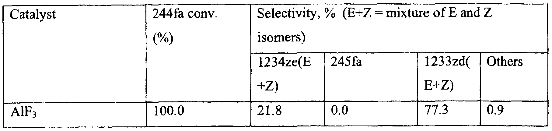
In Example 10, aluminum fluoride was used as dehydrohalogenation catalyst. 20 ml of catalyst was charged into a 3/«-inch diameter monel reactor. 244fa feed was passed through each catalyst at a rate of 12 grams/hour at a temperature of 350° C.
As shown in Table 5, the AlF3 catalyst provided a 1233zd selectivity of about 77% and a 1234ze selectivity of about 22%, indicating 1234ze and 1233zd can be co- produced from 244fa dehydrohalogenation over this catalyst. All 244fa was converted during the reaction.
Table 5
244fa dehydrohalogenation over a metal halide catalyst at 350° C
Figure imgf000028_0001
Example 11
This Example demonstrates the dehydrohalogenation of HCFC244fa is a caustic solution to produce both 1234ze(E) and 1233zd(E).
539.5 grams of 9.3 wt % KOH solution and 135.4 grams of 90.0 GC area % pure 3-chloro-l,l,l,3-tetrafluoropropane (HCFC-244fa) were added to a 1.0 liter stainless steel cylinder. The other major component was HCFO-1223xd which amounted to 9.2 GC area %. The cylinder was heated to 75° to 80° C and shaken for five (5) hours. A sample of the vapor space showed the presence of 75.6 area % HFO-1234ze trans isomer, 12.9 area % HFO-1234ze cis isomer, 8.5 GC area % HCFC-244fa, and 0.8 GC area % HCFO-1223xd. A sample of the organic liquid phase showed 24.4 GC area % HFO- 1234ze(E), 12.9 GC area % HCFO-1233zd(E) isomer, 44.2 GC area % HCFC-244fa, and 8.1 GC area % HCFO-1223xd.
560.0 grams of aqueous solution was collected after the experiment which amounts to a weight gain of 20.5 grams in the aqueous layer. Assuming this weight gain was HC1 that was produced during the dehydrochlorination of 244fa it was calculated that about a 60% conversion of HCFC-244fa to HFO-1234ze occurred during the reaction.
It should be understood that the foregoing description and examples are only illustrative of the present invention. Various alternatives and modifications can be devised by those skilled in the art without departing from the invention. Accordingly, the present invention is intended to embrace all such alternatives, modifications and variances that fall within the scope of the appended claims.

Claims

WHAT IS CLAIMED IS:
1. A process for the formation of trans- 1 -chloro-3,3,3-trifluoropropene and trans- 1,3,3,3-tetrafluoropropene comprising the steps of:
(a) reacting 1,1,1 ,3,3-pentachloropropane with hydrogen fluoride in the presence of a fluorination catalyst to co-produce trans-l-chloro-3,3,3-trifluoropropene and l-chloro-l,3,3,3-tetrafluoropropane; and
(b) dehydrochlorinating the l-chloro-1,3,3,3-tetrafluoropropane formed in step (a) to produce trans-l,3,3,3-tetrafluoropropene.
2. The process of claim 1, wherein the dehydrochlorination step takes place in the liquid phase by contact with a caustic solution.
3. The process of claim 1, wherein the dehydrochlorination step occurs in the vapor phase using a dehydrochlorination catalyst.
4. The process of claim 1, wherein the dehydrochlorination step further produces hydrogen chloride.
5. The process of claim 1 , wherein the reactions take place in a liquid phase reactor with excess hydrogen fluoride.
6. The process of claim 5, wherein the reactions are run using a relatively weak fluorination catalyst selected from the group consisting of TiCl4, SnCl4, TaCl5, SbCl3, AlCl3, SbCl5 , and mixtures thereof.
7. The process of claim of claim 6, wherein the catalyst is partially fluorinated.
8. The process of claim of claim 6, wherein the catalyst is totally fluorinated.
9. The process of claim 5, wherein the reactions are run under non-corrosive conditions whereby a metal or alloy reactor can be used.
10. The process of claim 5, wherein the process allows for flexibility in producing different amounts of each compound, simply by adjusting one or more of the following; operating conditions; concentrations of reactants; and catalyst employed in the liquid phase reactor.
PCT/US2011/028798 2010-04-05 2011-03-17 Integrated process to co-produce trans-1-chloro-3,3,3-trifluoropropene and trans-1,3,3,3-tetrafluoropropene WO2011126692A2 (en)

Priority Applications (6)

Application Number Priority Date Filing Date Title
EP11766356.7A EP2556042B1 (en) 2010-04-05 2011-03-17 Integrated process to co-produce trans-1-chloro-3,3,3-trifluoropropene and trans-1,3,3,3-tetrafluoropropene
PL11766356T PL2556042T3 (en) 2010-04-05 2011-03-17 Integrated process to co-produce trans-1-chloro-3,3,3-trifluoropropene and trans-1,3,3,3-tetrafluoropropene
ES11766356T ES2728464T3 (en) 2010-04-05 2011-03-17 Integrated process to co-produce trans-1-chloro-3,3,3-trifluoropropene and trans-1,3,3,3-tetrafluoropropene
JP2013503759A JP5792280B2 (en) 2010-04-05 2011-03-17 Integrated process for co-production of trans-1-chloro-3,3,3-trifluoropropene and trans-1,3,3,3-tetrafluoropropene
MX2012011450A MX2012011450A (en) 2010-04-05 2011-03-17 Integrated process to co-produce trans-1-chloro-3,3,3-trifluoropr opene and trans-1,3,3,3-tetrafluoropropene.
CN201180027570.4A CN102918010B (en) 2010-04-05 2011-03-17 Integrated process to co-produce trans-1-chloro-3,3,3-trifluoropropene and trans-1,3,3,3-tetrafluoropropene

Applications Claiming Priority (2)

Application Number Priority Date Filing Date Title
US12/754,070 US8426656B2 (en) 2010-04-05 2010-04-05 Integrated process to co-produce trans-1-chloro-3,3,3-trifluoropropene and trans-1,3,3,3-tetrafluoropropene
US12/754,070 2010-04-05

Publications (2)

Publication Number Publication Date
WO2011126692A2 true WO2011126692A2 (en) 2011-10-13
WO2011126692A3 WO2011126692A3 (en) 2012-01-05

Family

ID=44710404

Family Applications (1)

Application Number Title Priority Date Filing Date
PCT/US2011/028798 WO2011126692A2 (en) 2010-04-05 2011-03-17 Integrated process to co-produce trans-1-chloro-3,3,3-trifluoropropene and trans-1,3,3,3-tetrafluoropropene

Country Status (9)

Country Link
US (1) US8426656B2 (en)
EP (1) EP2556042B1 (en)
JP (1) JP5792280B2 (en)
CN (1) CN102918010B (en)
ES (1) ES2728464T3 (en)
MX (1) MX2012011450A (en)
PL (1) PL2556042T3 (en)
PT (1) PT2556042T (en)
WO (1) WO2011126692A2 (en)

Cited By (9)

* Cited by examiner, † Cited by third party
Publication number Priority date Publication date Assignee Title
WO2013115048A1 (en) * 2012-02-02 2013-08-08 セントラル硝子株式会社 Method for purifying (e)-1-chloro-3,3,3-trifluoropropene
WO2014010530A1 (en) * 2012-07-11 2014-01-16 セントラル硝子株式会社 Method for separating 1-chloro-3,3,3-trifluoropropene and hydrogen fluoride, and method for producing 1-chloro-3,3,3-trifluoropropene by using same
JP2015507009A (en) * 2012-02-14 2015-03-05 ハネウェル・インターナショナル・インコーポレーテッド Method for producing tetrafluoropropene
JP2015509096A (en) * 2012-01-25 2015-03-26 ダイキン工業株式会社 Method for producing fluorine-containing olefin
JP2015511946A (en) * 2012-02-15 2015-04-23 ハネウェル・インターナショナル・インコーポレーテッド Production method of HCFC-1233zd
EP2665695A4 (en) * 2011-01-19 2015-07-01 Honeywell Int Inc Integrated process to co-produce trans-1-chloro-3,3,3-trifluoropropene, trans-1,3,3,3-tetrafluoropropene, and 1,1,1,3,3-pentafluoropropane
EP2661420B1 (en) 2011-01-07 2015-07-15 Honeywell International Inc. Low temperature production of 2-chloro-3,3,3-trifluoropropene
EP2702018B1 (en) 2011-04-25 2015-09-30 Honeywell International Inc. INTEGRATED PROCESS TO CO-PRODUCE 1,1,1,3,3-PENTAFLUOROPROPANE, TRANS-1-CHLORO-3,3,3-TRIFLUOROPROPENE and TRANS-1,3,3,3-TETRAFLUOROPROPENE
EP2970062B1 (en) 2013-03-14 2019-10-09 Honeywell International Inc. Process to supress the formation of 3,3,3-trifluoropropyne in fluorocarbon manufacture

Families Citing this family (23)

* Cited by examiner, † Cited by third party
Publication number Priority date Publication date Assignee Title
US9045386B2 (en) 2010-02-18 2015-06-02 Honeywell International Inc. Integrated process and methods of producing (E)-1-chloro-3,3,3-trifluoropropene
US8044015B2 (en) * 2010-03-12 2011-10-25 Honeywell International Inc. 3-chloro 1,1,1,6,6,6-hexafluoro-2,4-hexadiene and solvent compositions containing the same
US8704017B2 (en) * 2010-09-03 2014-04-22 Honeywell International Inc. Continuous low-temperature process to produce trans-1-chloro-3,3,3-trifluoropropene
US8889924B2 (en) 2012-02-14 2014-11-18 Honeywell International Inc. Process for the production of 1,3,3,3-tetrafluoropropene
US9938212B2 (en) * 2012-03-28 2018-04-10 Honeywell International Inc. Integrated process to coproduce trans-1-chloro-3,3,3-trifluoropropene, trans-1,3,3,3-tetrafluoropropene, and 1,1,1,3,3-pentafluoropropane
US8664456B2 (en) * 2012-03-28 2014-03-04 Honeywell International Inc. Integrated process for the co-production of trans-1-chloro-3,3,3-trifluoropropene, trans-1,3,3,3-tetrafluoropropene, and 1,1,1,3,3-pentafluoropropane
US9000239B2 (en) 2012-05-15 2015-04-07 Honeywell International Inc. Methods for producing 1-chloro-3,3,3-trifluoropropene from 2-chloro-3,3,3-trifluoropropene
CA2935008C (en) 2014-01-13 2023-04-18 Arkema France Method for producing e-1-chloro-3,3,3-trifluoropropene from 1,1,3,3-tetrachloropropene
US9255045B2 (en) 2014-01-13 2016-02-09 Arkema France E-1-chloro-3,3,3-trifluoropropene production process from 1,1,3,3-tetrachloropropene
CN103861579B (en) * 2014-03-19 2016-01-13 西安近代化学研究所 A kind of trifluoro-ethylene catalyst for preparing
CN110845295A (en) 2014-08-14 2020-02-28 科慕埃弗西有限公司 Process for the preparation of E-1, 3,3, 3-tetrafluoropropene (HFC-1234ze) by dehydrofluorination
FR3036398B1 (en) 2015-05-22 2019-05-03 Arkema France COMPOSITIONS BASED ON 1,1,3,3-TETRACHLOROPROPENE
CN105152850B (en) * 2015-07-20 2017-02-01 淄博联创聚氨酯有限公司 Method for synthesizing cis/trans-1- chlorine-3,3,3-trifluoropropene
CN106349005B (en) 2016-08-25 2018-08-28 浙江衢州巨新氟化工有限公司 A kind of method of coproduction trifluoropropyl alkenes product and tetrafluoropropene class product
CN106866354B (en) * 2017-01-18 2019-06-21 浙江工业大学 A kind of preparation method of 1,1- difluoroethylene
CN107522592B (en) 2017-09-07 2020-06-02 浙江衢化氟化学有限公司 Method for coproducing various halogenated olefins and fluorinated alkanes
CN109596723B (en) * 2017-09-30 2022-04-19 浙江省化工研究院有限公司 Method for measuring impurities in cis-1, 3,3, 3-tetrafluoropropene by gas chromatography
CN107721809B (en) * 2017-10-19 2020-06-19 浙江衢化氟化学有限公司 Co-production method of 2,3,3, 3-tetrafluoropropene and trans-1, 3,3, 3-tetrafluoropropene
US10118879B1 (en) * 2017-10-26 2018-11-06 Honeywell International Inc. Process for catalytic conversion of mixtures of HCFO-1233zd(Z) and HCFC-244fa into HCFO-1233zd(E)
FR3081158B1 (en) 2018-05-16 2020-07-31 Arkema France PROCESS FOR THE PRODUCTION OF 1-CHLORO-3,3,3-TRIFLUOROPROPENE.
FR3083232B1 (en) 2018-06-27 2021-11-12 Arkema France 1-CHLORO-3,3,3-TRIFLUOROPROPENE PRODUCTION PROCESS
FR3086287B1 (en) 2018-09-26 2020-09-18 Arkema France STABILIZATION OF 1-CHLORO-3,3,3-TRIFLUOROPROPENE
CN113527041A (en) * 2020-04-22 2021-10-22 中化近代环保化工(西安)有限公司 Process for preparing cis-HFO-1234 ze from mixture containing HCFC-244fa

Citations (2)

* Cited by examiner, † Cited by third party
Publication number Priority date Publication date Assignee Title
US7230146B2 (en) 2003-10-27 2007-06-12 Honeywell International Inc. Process for producing fluoropropenes
US7485760B2 (en) 2006-08-24 2009-02-03 Honeywell International Inc. Integrated HFC trans-1234ze manufacture process

Family Cites Families (17)

* Cited by examiner, † Cited by third party
Publication number Priority date Publication date Assignee Title
EP0729932A1 (en) * 1995-03-03 1996-09-04 Central Glass Company, Limited Method of producing halopropane
US6235951B1 (en) 1996-01-17 2001-05-22 Central Glass Company, Limited Method for producing 1,1,1,3,3-pentafluoropropane
FR2748473B1 (en) * 1996-05-13 1998-07-24 Atochem Elf Sa SYNTHESIS OF 1-CHLORO-3,3,3 TRIFLUOROPROPENE AND ITS FLUORINATION IN 1,1,1,3,3 PENTAFLUOROPROPANE
US5710352A (en) 1996-09-19 1998-01-20 Alliedsignal Inc. Vapor phase process for making 1,1,1,3,3-pentafluoropropane and 1-chloro-3,3,3-trifluoropropene
US6023004A (en) * 1996-11-12 2000-02-08 Alliedsignal, Inc. Liquid phase catalytic fluorination of hydrochlorocarbon and hydrochlorofluorocarbon
EP0939071B1 (en) 1998-02-26 2003-07-30 Central Glass Company, Limited Method for producing fluorinated propane
BE1011765A3 (en) * 1998-02-26 2000-01-11 Solvay HYDROCARBONS hydrofluorination process.
US8530708B2 (en) * 2003-07-25 2013-09-10 Honeywell International Inc. Processes for selective dehydrohalogenation of halogenated alkanes
US7592494B2 (en) * 2003-07-25 2009-09-22 Honeywell International Inc. Process for the manufacture of 1,3,3,3-tetrafluoropropene
US6844475B1 (en) 2003-08-08 2005-01-18 Honeywell International Business Machines Low temperature production of 1-chloro-3,3,3-trifluoropropene (HCFC-1233zd)
US8058486B2 (en) 2004-04-29 2011-11-15 Honeywell International Inc. Integrated process to produce 2,3,3,3-tetrafluoropropene
US7678949B2 (en) 2005-08-05 2010-03-16 E.I. Du Pont De Nemours And Company Process for the preparation of 1,3,3,3-tetrafluoropropene and/or 2,3,3,3-tetrafluoropropene
US8324436B2 (en) 2006-01-03 2012-12-04 Honeywell International Inc. Gas phase synthesis of 2,3,3,3-tetrafluoro-1-propene from 2-chloro-3,3,3-trifluoro-1-propene
US9040759B2 (en) * 2007-07-06 2015-05-26 Honeywell International Inc. Preparation of fluorinated olefins via catalytic dehydrohalogenation of halogenated hydrocarbons
US7829747B2 (en) * 2008-04-24 2010-11-09 Honeywell International Inc. Process for dehydrofluorination of 3-chloro-1,1,1,3-tetrafluoropropane to 1-chloro-3,3,3-trifluoropropene
CN102164881B (en) 2008-09-25 2015-05-27 中央硝子株式会社 Process for producing 1,3,3,3-tetrafluoropropene
US8648221B2 (en) * 2011-01-19 2014-02-11 Honeywell International Inc. Integrated process to co-produce trans-1-chloro-3,3,3-trifluoropropene, trans-1,3,3,3-tetrafluoropropene, and 1,1,1,3,3-pentafluoropropane

Patent Citations (3)

* Cited by examiner, † Cited by third party
Publication number Priority date Publication date Assignee Title
US7230146B2 (en) 2003-10-27 2007-06-12 Honeywell International Inc. Process for producing fluoropropenes
US20070238908A1 (en) 2003-10-27 2007-10-11 Honeywell International Inc. Process for producing fluoropropenes
US7485760B2 (en) 2006-08-24 2009-02-03 Honeywell International Inc. Integrated HFC trans-1234ze manufacture process

Non-Patent Citations (2)

* Cited by examiner, † Cited by third party
Title
"Scientific Assessment of Ozone Depletion", 2002, WORLD METEOROLOGICAL ASSOCIATION
See also references of EP2556042A4

Cited By (15)

* Cited by examiner, † Cited by third party
Publication number Priority date Publication date Assignee Title
EP2661420B1 (en) 2011-01-07 2015-07-15 Honeywell International Inc. Low temperature production of 2-chloro-3,3,3-trifluoropropene
CN107892642A (en) * 2011-01-19 2018-04-10 霍尼韦尔国际公司 The integrated approach of the trans trifluoro propene of 1 chlorine 3,3,3 of Joint Production, tetrafluoropropene and pentafluoropropane
EP2665695A4 (en) * 2011-01-19 2015-07-01 Honeywell Int Inc Integrated process to co-produce trans-1-chloro-3,3,3-trifluoropropene, trans-1,3,3,3-tetrafluoropropene, and 1,1,1,3,3-pentafluoropropane
EP2702018B1 (en) 2011-04-25 2015-09-30 Honeywell International Inc. INTEGRATED PROCESS TO CO-PRODUCE 1,1,1,3,3-PENTAFLUOROPROPANE, TRANS-1-CHLORO-3,3,3-TRIFLUOROPROPENE and TRANS-1,3,3,3-TETRAFLUOROPROPENE
JP2015509096A (en) * 2012-01-25 2015-03-26 ダイキン工業株式会社 Method for producing fluorine-containing olefin
CN104093687A (en) * 2012-02-02 2014-10-08 中央硝子株式会社 Method for purifying (E)-1-chloro-3,3,3-trifluoropropene
WO2013115048A1 (en) * 2012-02-02 2013-08-08 セントラル硝子株式会社 Method for purifying (e)-1-chloro-3,3,3-trifluoropropene
US9321708B2 (en) 2012-02-02 2016-04-26 Central Glass Company, Limited Method for purifying (E)-1-chloro-3,3,3-trifluoropropene
JP2015507009A (en) * 2012-02-14 2015-03-05 ハネウェル・インターナショナル・インコーポレーテッド Method for producing tetrafluoropropene
JP2015511946A (en) * 2012-02-15 2015-04-23 ハネウェル・インターナショナル・インコーポレーテッド Production method of HCFC-1233zd
CN104520260A (en) * 2012-07-11 2015-04-15 中央硝子株式会社 Method for separating 1-chloro-3,3,3-trifluoropropene and hydrogen fluoride, and method for producing 1-chloro-3,3,3-trifluoropropene by using same
JP2014051485A (en) * 2012-07-11 2014-03-20 Central Glass Co Ltd Separation method of 1-chloro-3,3,3-trifluoropropene and hydrogen fluoride, and production method of 1-chloro-3,3,3-trifluoropropene using the same
US9221732B2 (en) 2012-07-11 2015-12-29 Central Glass Company, Limited Method for separating 1-chloro-3,3,3-trifluoropropene and hydrogen fluoride, and method for producing 1-chloro-3,3,3-trifluoropropene by using same
WO2014010530A1 (en) * 2012-07-11 2014-01-16 セントラル硝子株式会社 Method for separating 1-chloro-3,3,3-trifluoropropene and hydrogen fluoride, and method for producing 1-chloro-3,3,3-trifluoropropene by using same
EP2970062B1 (en) 2013-03-14 2019-10-09 Honeywell International Inc. Process to supress the formation of 3,3,3-trifluoropropyne in fluorocarbon manufacture

Also Published As

Publication number Publication date
CN102918010B (en) 2015-02-25
JP2013523812A (en) 2013-06-17
ES2728464T3 (en) 2019-10-24
US20110245549A1 (en) 2011-10-06
JP5792280B2 (en) 2015-10-07
US8426656B2 (en) 2013-04-23
EP2556042A4 (en) 2014-02-19
PL2556042T3 (en) 2019-08-30
MX2012011450A (en) 2013-01-25
EP2556042A2 (en) 2013-02-13
EP2556042B1 (en) 2019-03-13
PT2556042T (en) 2019-06-11
CN102918010A (en) 2013-02-06
WO2011126692A3 (en) 2012-01-05

Similar Documents

Publication Publication Date Title
US8426656B2 (en) Integrated process to co-produce trans-1-chloro-3,3,3-trifluoropropene and trans-1,3,3,3-tetrafluoropropene
US8648221B2 (en) Integrated process to co-produce trans-1-chloro-3,3,3-trifluoropropene, trans-1,3,3,3-tetrafluoropropene, and 1,1,1,3,3-pentafluoropropane
US8436217B2 (en) Integrated process to co-produce 1,1,1,3,3-pentafluoropropane, trans-1-chloro-3,3,3-trifluoropropene and trans-1,3,3,3-tetrafluoropropene
US10155706B2 (en) Process for producing 2,3,3,3-tetrafluoropropene
US8664456B2 (en) Integrated process for the co-production of trans-1-chloro-3,3,3-trifluoropropene, trans-1,3,3,3-tetrafluoropropene, and 1,1,1,3,3-pentafluoropropane
JP5974003B2 (en) For co-production of trans-1-chloro-3,3,3-trifluoropropene, trans-1,3,3,3-tetrafluoropropene, and 1,1,1,3,3-pentafluoropropane Integration method
US9938212B2 (en) Integrated process to coproduce trans-1-chloro-3,3,3-trifluoropropene, trans-1,3,3,3-tetrafluoropropene, and 1,1,1,3,3-pentafluoropropane
WO2009018561A2 (en) Method for producing fluorinated organic compounds

Legal Events

Date Code Title Description
WWE Wipo information: entry into national phase

Ref document number: 201180027570.4

Country of ref document: CN

121 Ep: the epo has been informed by wipo that ep was designated in this application

Ref document number: 11766356

Country of ref document: EP

Kind code of ref document: A2

WWE Wipo information: entry into national phase

Ref document number: 2011766356

Country of ref document: EP

WWE Wipo information: entry into national phase

Ref document number: MX/A/2012/011450

Country of ref document: MX

WWE Wipo information: entry into national phase

Ref document number: 2013503759

Country of ref document: JP

NENP Non-entry into the national phase

Ref country code: DE

WWE Wipo information: entry into national phase

Ref document number: 9169/DELNP/2012

Country of ref document: IN