WO2011125996A1 - 基地局装置、移動端末装置および通信制御方法 - Google Patents
基地局装置、移動端末装置および通信制御方法 Download PDFInfo
- Publication number
- WO2011125996A1 WO2011125996A1 PCT/JP2011/058573 JP2011058573W WO2011125996A1 WO 2011125996 A1 WO2011125996 A1 WO 2011125996A1 JP 2011058573 W JP2011058573 W JP 2011058573W WO 2011125996 A1 WO2011125996 A1 WO 2011125996A1
- Authority
- WO
- WIPO (PCT)
- Prior art keywords
- mobile terminal
- base station
- terminal apparatus
- fundamental frequency
- communication system
- Prior art date
- Legal status (The legal status is an assumption and is not a legal conclusion. Google has not performed a legal analysis and makes no representation as to the accuracy of the status listed.)
- Ceased
Links
Images





Classifications
-
- H—ELECTRICITY
- H04—ELECTRIC COMMUNICATION TECHNIQUE
- H04L—TRANSMISSION OF DIGITAL INFORMATION, e.g. TELEGRAPHIC COMMUNICATION
- H04L1/00—Arrangements for detecting or preventing errors in the information received
- H04L1/12—Arrangements for detecting or preventing errors in the information received by using return channel
- H04L1/16—Arrangements for detecting or preventing errors in the information received by using return channel in which the return channel carries supervisory signals, e.g. repetition request signals
- H04L1/18—Automatic repetition systems, e.g. Van Duuren systems
- H04L1/1829—Arrangements specially adapted for the receiver end
- H04L1/1854—Scheduling and prioritising arrangements
-
- H—ELECTRICITY
- H04—ELECTRIC COMMUNICATION TECHNIQUE
- H04L—TRANSMISSION OF DIGITAL INFORMATION, e.g. TELEGRAPHIC COMMUNICATION
- H04L1/00—Arrangements for detecting or preventing errors in the information received
- H04L1/12—Arrangements for detecting or preventing errors in the information received by using return channel
- H04L1/16—Arrangements for detecting or preventing errors in the information received by using return channel in which the return channel carries supervisory signals, e.g. repetition request signals
- H04L1/18—Automatic repetition systems, e.g. Van Duuren systems
- H04L1/1829—Arrangements specially adapted for the receiver end
- H04L1/1861—Physical mapping arrangements
-
- H—ELECTRICITY
- H04—ELECTRIC COMMUNICATION TECHNIQUE
- H04L—TRANSMISSION OF DIGITAL INFORMATION, e.g. TELEGRAPHIC COMMUNICATION
- H04L5/00—Arrangements affording multiple use of the transmission path
- H04L5/0001—Arrangements for dividing the transmission path
- H04L5/0003—Two-dimensional division
- H04L5/0005—Time-frequency
- H04L5/0007—Time-frequency the frequencies being orthogonal, e.g. OFDM(A) or DMT
- H04L5/001—Time-frequency the frequencies being orthogonal, e.g. OFDM(A) or DMT the frequencies being arranged in component carriers
-
- H—ELECTRICITY
- H04—ELECTRIC COMMUNICATION TECHNIQUE
- H04L—TRANSMISSION OF DIGITAL INFORMATION, e.g. TELEGRAPHIC COMMUNICATION
- H04L5/00—Arrangements affording multiple use of the transmission path
- H04L5/0001—Arrangements for dividing the transmission path
- H04L5/0014—Three-dimensional division
- H04L5/0016—Time-frequency-code
-
- H—ELECTRICITY
- H04—ELECTRIC COMMUNICATION TECHNIQUE
- H04L—TRANSMISSION OF DIGITAL INFORMATION, e.g. TELEGRAPHIC COMMUNICATION
- H04L5/00—Arrangements affording multiple use of the transmission path
- H04L5/003—Arrangements for allocating sub-channels of the transmission path
- H04L5/0048—Allocation of pilot signals, i.e. of signals known to the receiver
- H04L5/0051—Allocation of pilot signals, i.e. of signals known to the receiver of dedicated pilots, i.e. pilots destined for a single user or terminal
-
- H—ELECTRICITY
- H04—ELECTRIC COMMUNICATION TECHNIQUE
- H04L—TRANSMISSION OF DIGITAL INFORMATION, e.g. TELEGRAPHIC COMMUNICATION
- H04L5/00—Arrangements affording multiple use of the transmission path
- H04L5/003—Arrangements for allocating sub-channels of the transmission path
- H04L5/0053—Allocation of signalling, i.e. of overhead other than pilot signals
- H04L5/0055—Physical resource allocation for ACK/NACK
-
- H—ELECTRICITY
- H04—ELECTRIC COMMUNICATION TECHNIQUE
- H04W—WIRELESS COMMUNICATION NETWORKS
- H04W72/00—Local resource management
-
- H—ELECTRICITY
- H04—ELECTRIC COMMUNICATION TECHNIQUE
- H04W—WIRELESS COMMUNICATION NETWORKS
- H04W72/00—Local resource management
- H04W72/12—Wireless traffic scheduling
-
- H—ELECTRICITY
- H04—ELECTRIC COMMUNICATION TECHNIQUE
- H04W—WIRELESS COMMUNICATION NETWORKS
- H04W88/00—Devices specially adapted for wireless communication networks, e.g. terminals, base stations or access point devices
- H04W88/08—Access point devices
- H04W88/10—Access point devices adapted for operation in multiple networks, e.g. multi-mode access points
Definitions
- the present invention relates to a base station apparatus, a mobile terminal apparatus, and a communication control method in a next generation mobile communication system.
- UMTS Universal Mobile Telecommunications System
- WSDPA High Speed Downlink Packet Access
- HSUPA High Speed Uplink Packet Access
- CDMA Wideband Code Division Multiple Access
- LTE Long Term Evolution
- OFDMA Orthogonal Frequency Division Multiple Access
- SC-FDMA Single Carrier Frequency Multiple Access
- the third generation system can achieve a maximum transmission rate of about 2 Mbps on the downlink using generally a fixed bandwidth of 5 MHz.
- a maximum transmission rate of about 300 Mbps on the downlink and about 75 Mbps on the uplink can be realized using a variable band of 1.4 MHz to 20 MHz.
- LTE-A LTE Advanced
- the present invention has been made in view of such points, and an object of the present invention is to provide a base station apparatus, a mobile terminal apparatus, and a communication control method corresponding to each mobile communication system when a plurality of mobile communication systems coexist.
- the first communication system having a system band composed of a plurality of fundamental frequency blocks overlaps with the second communication system having a system band composed of a single fundamental frequency block.
- a response signal generating unit that generates a response signal for retransmission with respect to an uplink received signal received by the plurality of basic frequency blocks, and the plurality of basic frequency blocks And an allocation unit that allocates the response signal by adding an offset to the allocation resource of the response signal, and the offset amount is set to 0 for a basic frequency block used in the second communication system
- the basic frequency block is set to be larger in the order of circulation between the plurality of basic frequency blocks. .
- the offset amount for the basic frequency block used in the second communication system is set to 0, and the offset amount is set to be larger in the order of circulation between the plurality of basic frequency blocks starting from this basic frequency block. ing. Therefore, collision of response signal allocation resources can be avoided at the time of SPS (Semi-Persistent Scheduling) transmission using cross carrier scheduling by using different offset amounts set for each of a plurality of basic frequency blocks. Further, in the basic frequency block used in the second communication system, even when the second communication system does not support offset, the offset amount with respect to the first communication system is 0. It is possible to avoid a collision of response signal allocation resources due to an offset being added only to.
- SPS Semi-Persistent Scheduling
- FIG. 1 is a diagram for explaining a frequency usage state when mobile communication is performed in the downlink.
- the example shown in FIG. 1 is relatively different from the LTE-A system, which is a first communication system having a relatively wide first system band composed of a plurality of basic frequency blocks (hereinafter, component carriers: CC).
- component carriers CC
- This is a frequency usage state when an LTE system, which is a second communication system having a second system band that is narrow (here, configured by one component carrier) coexists.
- LTE-A system for example, wireless communication is performed with a variable system bandwidth of 100 MHz or less, and in the LTE system, wireless communication is performed with a variable system bandwidth of 20 MHz or less.
- the system band of the LTE-A system is at least one basic frequency block having the system band of the LTE system as a unit. In this way, widening a band by combining a plurality of basic frequency blocks is called carrier aggregation.
- Mobile terminal apparatus having a system band of 20 MHz (base band).
- the base station apparatus performs HARQ (Hybrid Automatic Repeat reQuest) ACK or NACK for uplink transmission (PUSCH: Physical Uplink Shared Channel) with PHICH (Physical Hybrid-ARQ Indicator CHannel).
- HARQ Hybrid Automatic Repeat reQuest
- NACK uplink transmission
- PUSCH Physical Uplink Shared Channel
- PHICH Physical Hybrid-ARQ Indicator CHannel
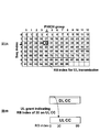
- the PHICH resource is, for example, as shown in FIG. It is specified by index.
- the PHICH group is divided for each predetermined frequency band. Seq. The index indicates an orthogonal code number used in the same frequency band (same PHICH group).
- PHICH is FDM (Frequency Division Multiplexing) multiplexed between a plurality of PHICH groups, and CDM (Code Division Multiplexing) multiplexed within the same PHICH group.
- PHICH resources are allocated according to the uplink transmission resource block number (RB index) indicated by the UL grant as shown in FIG. 2B. Since it is a single carrier (SC-FDMA) in the uplink, the head resource block number Ilow of the resource block that is continuous in the UL grant is indicated.
- the PHICH resource is allocated with the PHICH group “4” and Seq.index “2”.
- the illustrated DL CC indicates the downlink of the component carrier
- the UL CC indicates the uplink of the component carrier.
- CS Cyclic Shift
- DM RS Demodulation Reference Signal
- the PHICH resource of the other mobile terminal apparatus is assigned as the CS value “1” in the PHICH group “5” and Seq.index “3”.
- PHICH resources are allocated based on the head resource block number I low for uplink transmission and the CS value.
- cross-carrier scheduling is a method of transmitting a downlink control channel using a carrier different from that having less influence of interference, for example, instead of a component carrier that has received strong interference. For example, as illustrated in FIG. 4A, when the downlink of the component carrier CC # 1 receives strong interference, the UL grant is notified through the downlink control channel of the component carrier CC # 0.
- the SPS is a method in which a permanent resource is set from the base station apparatus to the mobile terminal apparatus, and the activation of the persistent resource is controlled in the base station apparatus to perform semi-persistent scheduling. In this case, a method of avoiding a PHICH resource collision by adding an offset to the PHICH resource for each component carrier can be considered.
- a PHICH resource to which an offset is added for each component carrier is obtained by Expression (1).
- n cc represents a CC number (CC index) set for each component carrier
- k represents a coefficient.
- n cc k obtained by multiplying the CC number n cc and the coefficient k indicates the offset amount set for each component carrier.
- the offset amount (n cc k) is varied between component carriers by the CC number (n cc ) allocated to each component carrier.
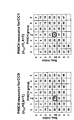
- the PHICH resource for I low “30” of component carrier CC # 1 is offset by one group in the PHICH group direction with respect to the PHICH resource for I low “30” of component carrier CC # 0. Collision is avoided. For this reason, even when the same I low is instructed to a plurality of component carriers during SPS transmission using cross carrier scheduling, collision of PHICH resources can be avoided.
- PHICH resources may collide.
- CC numbers n cc
- I low “29” is instructed to the uplink of the component carriers CC # 0 and CC # 1 by the UL grant (Rel. 10 UL grant).
- I low “30” is instructed to the uplink of the component carrier CC # 1 by the UL grant (Rel. 8 UL grant).
- an offset is added only to the PHICH resource for I low “29” of the LTE-A system.
- an offset (n cc k) for one group is added to the PHICH group direction of the LTE-A in the PHICH group direction. Therefore, as shown in FIG. 6B, the same PHICH resource (PHICH group “2”, Seq.index “4”) is assigned to I low “30” of the LTE system and I low “29” of the LTE-A system.
- the present inventors have come up with the present invention in order to solve this problem. That is, the gist of the present invention is that PHICH resources collide during SPS transmission using cross-carrier scheduling when multiple communication systems coexist, and PHICH resource collisions are devised by devising how to add offsets. Is to avoid.
- the offset amount for a component carrier commonly used in the LTE system and the LTE-A system is set to 0, and the offset amount is set to be large in the order of circulation between the plurality of component carriers starting from this component carrier. Yes.
- an offset is not added only to the PHICH resource of the LTE-A system in the component carrier used in the LTE system. Therefore, when a plurality of communication systems coexist, a collision of PHICH resources with an uplink signal of each component carrier is avoided during SPS transmission using cross carrier scheduling.
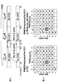
- FIG. 7 is an explanatory diagram showing an example of a PHICH resource allocation method in a radio communication system in which an LTE-A system as a first communication system and an LTE system as a second communication system are mixed.
- the wireless communication system has a system band composed of component carriers CC # 0 to CC # 2.
- communication is performed by the component carrier CC # 1, and I low is instructed to the uplink of the component carrier CC # 1 by the UL grant (Rel.8 UL grant).
- the UL grant (Rel.8 UL grant).
- communication is performed on the component carriers CC # 0 to CC # 2, and the downlink of the component carrier CC # 0 receives strong interference.
- I low is indicated for the uplinks of the component carriers CC # 0 and CC # 1 by the UL grant (Rel.10 UL grant) of the component carrier CC # 1 by cross carrier scheduling. ing.
- CC numbers are assigned to the component carriers CC # 0 to CC # 2, respectively.
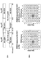
- the offset amount (n cc k) is 0 from Equation (1), and no offset is added to the PHICH resource in both the LTE system and the LTE-A system.
- the collision of the PHICH resource of the LTE system and the LTE-A system is avoided.
- the component carrier CC # 1 of the uplink, I low "29" is indicated in the LTE-A system
- I low "30” is indicated in the LTE system. Therefore, as shown in FIG. 7B, the same PHICH resource is not allocated to the I low “30” of the LTE system and the I low “29” of the LTE-A system, and collision of PHICH resources is avoided.
- the base station apparatus is configured to calculate the PHICH resource using Equation (1), but is not limited to this configuration. As long as the base station apparatus can calculate the PHICH resource for each component carrier, the calculation method is not limited.
- the base station apparatus has a configuration in which a different offset amount is set for each component carrier by assigning a CC number for each component carrier.
- the configuration is not limited to this configuration.
- the wireless communication system may have any configuration as long as the offset amount set to the component carrier used in the LTE system is 0 and a different offset amount is set for each component carrier.
- the cyclic direction for setting the offset amount has been described as the order of the component carriers CC # 1, CC # 2, CC # 0, it may be in the reverse direction.
- PHICH resource identification information allocation resource identification information
- FIG. 8 is an explanatory diagram of a first notification method of PHICH resource specifying information for the mobile terminal device.
- the cross-carrier scheduling uses a downlink control channel of an anchor carrier that is less affected by interference, instead of a component carrier that has received strong interference from another cell.
- a 3-bit bit field (CIF: Carrier Indicator Field) for setting a carrier identifier (CI: Carrier Indicator) is added to downlink control information (PDCCH: Physical Downlink Control CHannel).
- the carrier identifier is information for causing the mobile terminal device to identify the transmission carrier.
- the CIF is associated with the CC number, and the offset amount added to the PHICH resource is notified from the base station apparatus to the mobile terminal apparatus by this CIF.
- a CC number with an offset amount of 0 is associated with the CIF of the component carrier CC # 1 used in the LTE system.
- CC numbers corresponding to relative shift amounts (intervals) from the component carrier CC # 1 in the cyclic direction are associated with the CIFs of the other component carriers CC # 0 and CC # 2.
- component carriers CC # 0, CC # 1, and CC # 2 are indicated by CIF “010”, CIF “000”, and CIF “001”, respectively.
- the CIF may be fixedly assigned to each component carrier, or may be dynamically assigned as long as it can be identified by the mobile terminal apparatus.
- the CIF and the CC number are associated with each other.
- the mobile terminal device may be configured to be able to identify the PHICH resource from the CIF, and the CIF and the offset amount (for example, n cc k) may be associated with each other.
- FIG. 9 is an explanatory diagram of a second notification method of PHICH resource specifying information for the mobile terminal device.
- a permanent resource is set from the base station device to the mobile terminal device, and the base station device controls activation of the permanent resource to perform semi-persistent scheduling.
- the persistent resource is transmitted to the mobile terminal device by SPS-Config notified by RRC (Radio Resource Control) signaling from the base station device. Is set.
- activation of the allocated persistent resource is controlled by the SPS-CRNTI notified from the base station apparatus. For example, after 4 subframes (4 msec) from the timing at which the SPS-CRNTI is received, the mobile terminal apparatus transmits uplink data using a PUSCH resource with a constant period (20 msec) indicated by the PDCCH.
- PHICH resources include PHICH group and Seq. “index” is notified.
- CC number the relative shift amount (interval) in the cyclic direction is notified to the component carrier used in the LTE system.
- the offset amount for example, n cc k in Expression (1) is notified. Therefore, the mobile terminal apparatus can identify the PHICH resource by receiving the PHICH resource, the CC number, the offset amount, and the like by higher layer signaling from the base station apparatus.
- FIG. 10 is a diagram for explaining the configuration of the radio communication system 1 including the mobile terminal apparatus 10 and the base station apparatus 20 according to the present embodiment.
- the radio communication system 1 illustrated in FIG. 10 is a system including, for example, an LTE system or SUPER 3G.
- the wireless communication system 1 may be called IMT-Advanced or 4G.
- the wireless communication system 1 includes a base station device 20 and a plurality of mobile terminal devices 10 (10 1 , 10 2 , 10 3 ,... 10 n , n communicating with the base station device 20. Is an integer of n> 0).
- the base station apparatus 20 is connected to the higher station apparatus 30, and the higher station apparatus 30 is connected to the core network 40.
- the mobile terminal apparatus 10 can communicate with the base station apparatus 20 in the cell 50.
- the upper station apparatus 30 includes, for example, an access gateway apparatus, a radio network controller (RNC), a mobility management entity (MME), and the like, but is not limited thereto.
- RNC radio network controller
- MME mobility management entity
- Each mobile terminal device (10 1 , 10 2 , 10 3 ,... 10 n ) includes an LTE terminal and an LTE-A terminal.
- the mobile terminal device 10 will be described unless otherwise specified. Proceed. For convenience of explanation, it is assumed that the mobile terminal device 10 is in radio communication with the base station device 20, but more generally, user equipment (UE: User Equipment) including both the mobile terminal device and the fixed terminal device. It's okay.
- UE User Equipment
- OFDMA orthogonal frequency division multiple access
- SC-FDMA single carrier-frequency division multiple access
- OFDMA is a multi-carrier transmission scheme that performs communication by dividing a frequency band into a plurality of narrow frequency bands (subcarriers) and mapping data to each subcarrier.
- SC-FDMA is a single carrier transmission method that reduces interference between terminals by dividing a system band into bands each consisting of one or continuous resource blocks for each terminal, and a plurality of terminals using different bands. .
- the uplink communication channel includes a PUSCH shared and used by each mobile terminal apparatus 10 and a PUCCH (Physical Uplink Control Channel) that is an uplink control channel. User data is transmitted by this PUSCH. Further, intra-subframe frequency hopping is applied to the PUCCH, and downlink radio quality information (CQI: Channel Quality Indicator), ACK / NACK, and the like are transmitted.
- PUCCH Physical Uplink Control Channel
- CQI Channel Quality Indicator
- the base station apparatus 20 includes a transmission / reception antenna 201, an amplifier unit 202, a transmission / reception unit 203, a baseband signal processing unit 204, a call processing unit 205, and a transmission path interface 206.
- User data transmitted from the base station apparatus 20 to the mobile terminal apparatus 10 via the downlink is input from the higher station apparatus 30 to the baseband signal processing unit 204 via the transmission path interface 206.
- the baseband signal processing unit 204 performs PDCP layer processing, user data division / combination, RLC layer transmission processing such as RLC (Radio Link Control) retransmission control transmission processing, MAC (Medium Access Control) retransmission control, for example, HARQ (Hybrid Automatic Repeat reQuest) transmission processing, scheduling, transmission format selection, channel encoding, Inverse Fast Fourier Transform (IFFT) processing, and precoding processing are performed. Also, transmission processing such as channel coding and inverse fast Fourier transform is performed on the signal of the physical downlink control channel that is the downlink control channel.
- RLC layer transmission processing such as RLC (Radio Link Control) retransmission control transmission processing, MAC (Medium Access Control) retransmission control, for example, HARQ (Hybrid Automatic Repeat reQuest) transmission processing, scheduling, transmission format selection, channel encoding, Inverse Fast Fourier Transform (IFFT) processing, and precoding processing are performed.
- transmission processing such as channel coding and inverse fast Fourier transform is
- the baseband signal processing unit 204 notifies the mobile terminal device 10 connected to the same cell 50 of the control information for each mobile terminal device 10 to perform wireless communication with the base station device 20 through the broadcast channel.
- the broadcast information for communication in the cell 50 includes, for example, identification information of a route sequence for generating a system bandwidth in the uplink or downlink and a random access preamble signal in PRACH (Physical Random Access CHannel) ( Root Sequence Index) etc. are included.
- the transmission / reception unit 203 frequency-converts the baseband signal output from the baseband signal processing unit 204 into a radio frequency band.
- the amplifier unit 202 amplifies the transmission signal subjected to frequency conversion and outputs the amplified transmission signal to the transmission / reception antenna 201.
- a radio frequency signal received by the transmission / reception antenna 201 is amplified by the amplifier unit 202 and is frequency-converted by the transmission / reception unit 203 to be baseband.
- the signal is converted into a signal and input to the baseband signal processing unit 204.
- the baseband signal processing unit 204 performs FFT processing, IDFT processing, error correction decoding, MAC retransmission control reception processing, RLC layer, PDCP layer reception processing on user data included in the baseband signal received in the uplink I do.
- the decoded signal is transferred to the higher station apparatus 30 via the transmission path interface 206.
- the call processing unit 205 performs call processing such as communication channel setting and release, state management of the base station device 20, and wireless resource management.
- the mobile terminal device 10 includes a transmission / reception antenna 101, an amplifier unit 102, a transmission / reception unit 103, a baseband signal processing unit 104, and an application unit 105.
- a radio frequency signal received by the transmission / reception antenna 101 is amplified by the amplifier unit 102, frequency-converted by the transmission / reception unit 103, and converted into a baseband signal.
- the baseband signal is subjected to FFT processing, error correction decoding, retransmission control reception processing, and the like by the baseband signal processing unit 104.
- downlink user data is transferred to the application unit 105.
- the application unit 105 performs processing related to layers higher than the physical layer and the MAC layer. Also, the broadcast information in the downlink data is also transferred to the application unit 105.
- uplink user data is input from the application unit 105 to the baseband signal processing unit 104.
- the baseband signal processing unit 104 performs transmission processing for retransmission control (HARQ (Hybrid ARQ)), channel coding, DFT processing, and IFFT processing.
- HARQ Hybrid ARQ
- the transmission / reception unit 103 converts the baseband signal output from the baseband signal processing unit 104 into a radio frequency band. Thereafter, the signal is amplified by the amplifier unit 102 and transmitted from the transmission / reception antenna 101.
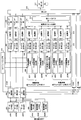
- FIG. 13 is a functional block diagram of the baseband signal processing unit 204 and some upper layers included in the base station apparatus 20 according to the present embodiment. Mainly, functional blocks of the transmission processing unit of the baseband signal processing unit 204 Is shown. FIG. 13 illustrates a base station configuration that can support the maximum number of M (CC # 1 to CC # M) component carriers. Transmission data for the mobile terminal apparatus 10 under the control of the base station apparatus 20 is transferred from the upper station apparatus 30 to the base station apparatus 20.
- M maximum number of M
- the control information generation unit 300 generates higher control information for higher layer signaling (for example, RRC signaling) for each user.
- the upper control information can include a command for requesting the carrier number of the anchor carrier, addition / reduction of component carriers, and CIF “ON” and “OFF”.
- SPS-Config can be included in the upper control information.
- the SPS-config can include at least one of a PHICH resource, a CC number, and an offset amount in addition to the period of the permanent resource allocated to the mobile terminal device.
- the data generation unit 301 outputs the transmission data transferred from the higher station apparatus 30 as user data for each user.
- the component carrier selection unit 302 selects a component carrier used for wireless communication with the mobile terminal device 10 for each user.
- the scheduling unit 310 controls the allocation of component carriers to the subordinate mobile terminal devices 10 according to the communication quality of the entire system band. Scheduling section 310 controls resource allocation in component carriers CC # 1 to CC # M. Scheduling is performed by distinguishing between LTE terminal users and LTE-A terminal users.
- the scheduling unit 310 receives transmission data and a retransmission instruction from the higher station apparatus 30 and receives a channel estimation value and a CQI of a resource block from a receiving unit that measures an uplink signal.
- the scheduling unit 310 performs scheduling of the up / down control information and the up / down shared channel signal while referring to the retransmission instruction, the channel estimation value, and the CQI input from the higher station apparatus 30.
- the propagation path in mobile communication varies depending on the frequency due to frequency selective fading. Therefore, when transmitting user data to the mobile terminal apparatus 10, resource blocks with good communication quality are assigned to each mobile terminal apparatus 10 for each subframe (referred to as adaptive frequency scheduling).
- adaptive frequency scheduling a mobile terminal apparatus 10 with good channel quality is selected and assigned to each resource block. Therefore, the scheduling unit 310 allocates resource blocks using the CQI for each resource block fed back from each mobile terminal apparatus 10. Also, an MCS (coding rate, modulation scheme) that satisfies a predetermined block error rate with the allocated resource block is determined. Parameters satisfying the MCS (coding rate, modulation scheme) determined by the scheduling unit 310 are set in the channel coding units 303, 308, 312 and the modulation units 304, 309, 313.
- the baseband signal processing unit 204 includes a channel encoding unit 303, a modulation unit 304, and a mapping unit 305 corresponding to the maximum user multiplexing number N in one component carrier.
- the channel coding unit 303 channel-codes a shared data channel (PDSCH) configured by user data (including some higher control signals) output from the data generation unit 301 for each user.
- the modulation unit 304 modulates channel-coded user data for each user.
- the mapping unit 305 maps the modulated user data to radio resources.
- the baseband signal processing unit 204 includes a downlink control information generation unit 306 that generates downlink shared data channel control information that is user-specific downlink control information, and a downlink common control channel control that is user-specific downlink control information. And a downlink common channel control information generating unit 307 that generates information.
- the baseband signal processing unit 204 includes a channel encoding unit 308 and a modulation unit 309 corresponding to the maximum user multiplexing number N in one component carrier.
- the channel coding unit 308 channel-codes the control information generated by the downlink control information generation unit 306 and the downlink common channel control information generation unit 307 for each user.
- Modulation section 309 modulates channel-coded downlink control information.
- the baseband signal processing unit 204 generates uplink shared data channel control information (UL grant or the like) that is control information for controlling the uplink shared data channel (PUSCH) for each user. And a channel encoding unit 312 for channel-coding the generated uplink shared data channel control information for each user, and a modulation unit 313 for modulating the channel-encoded uplink shared data channel control information for each user.
- uplink shared data channel control information UL grant or the like
- PUSCH uplink shared data channel
- the control information modulated for each user by the modulation units 309 and 313 is multiplexed by the control channel multiplexing unit 314 and further interleaved by the interleaving unit 315.
- the control signal output from the interleaving unit 315 and the user data output from the mapping unit 305 are input to the IFFT unit 316 as downlink channel signals.
- the IFFT unit 316 converts the downlink channel signal from a frequency domain signal to a time-series signal by performing inverse fast Fourier transform.
- the cyclic prefix insertion unit 317 inserts a cyclic prefix into the time-series signal of the downlink channel signal.
- the cyclic prefix functions as a guard interval for absorbing a difference in multipath propagation delay.
- the transmission data to which the cyclic prefix is added is sent to the transmission / reception unit 203.
- FIG. 14 is a functional block diagram of the baseband signal processing unit 104 included in the mobile terminal apparatus 10, and shows functional blocks of an LTE-A terminal that supports LTE-A. First, the downlink configuration of the mobile terminal apparatus 10 will be described.
- the baseband signal processing unit 104 includes a control information demodulation unit 405 that demodulates control information, a data demodulation unit 406 that demodulates downlink shared data, and a channel estimation unit 407.
- the control information demodulator 405 includes a common control channel control information demodulator 405a that demodulates downlink common control channel control information from the multiplex control information, and an uplink shared data channel that demodulates uplink shared data channel control information from the multiplex control information. And a downlink shared data channel control information demodulator 405c that demodulates downlink shared data channel control information from the multiplexed control information.
- the data demodulator 406 includes a downlink shared data demodulator 406a that demodulates user data and higher control signals, and a downlink common channel data demodulator 406b that demodulates downlink common channel data.
- the uplink shared data channel control information demodulator 405b is used for uplink shared data channel that is user-specific uplink control information by blind decoding processing, demodulation processing, channel decoding processing, etc. of the user-specific search space of multiplex control information (PDCCH). retrieve control information. As the uplink shared data channel control information, for example, the head resource block number I low for uplink transmission is extracted.
- the uplink shared data channel control information is used to control the uplink shared data channel (PUSCH), and is input to the downlink shared data channel control information demodulator 405c and the downlink common channel data demodulator 406b.
- the downlink shared data channel control information demodulator 405c is used for the downlink shared data channel that is a downlink control signal unique to the user by blind decoding processing, demodulation processing, channel decoding processing, etc. of the user-specific search space of the multiplex control information (PDCCH) retrieve control information. Further, the downlink shared data channel control information is used for controlling the downlink shared data channel (PDSCH), and is input to the downlink shared data demodulation unit 406. Also, the downlink shared data channel control information demodulator 405c performs a blind decoding process on the user-specific search space based on the information related to the PDCCH and PDSCH included in the upper control information demodulated by the downlink shared data demodulator 406a. Do.
- the downlink shared data channel control information demodulation section 405c may specify the PHICH resource by the CIF notified from the base station apparatus 20.
- the downlink shared data channel control information demodulator 405c obtains an offset amount based on the CC number (n cc ) associated with the CIF, specifies the PHICH resource corresponding to I low, and transmits the HARQ ACK. / NACK is taken out.
- the downlink shared data channel control information demodulation section 405c may specify the PHICH resource by higher order signaling from the base station apparatus 20.
- the downlink shared data demodulation section 406a demodulates the RRC signaling notifying the SPS-Config as the upper control information, and determines the contents of the SPS-Config in the upper layer.
- the downlink shared data channel control information demodulator 405c identifies the PHICH resource corresponding to I low by feeding back at least one of the PHICH resource, CC number, and offset amount included in the SPS-Config from the upper layer. Then, ACK / NACK for HARQ is taken out.
- the downlink shared data demodulator 406a acquires user data and higher control information based on the downlink shared data channel control information input from the downlink shared data channel control information demodulator 405c. Upper control information (including mode information) is output to channel estimation section 407.
- the downlink common channel data demodulation unit 406b demodulates the downlink common channel data based on the uplink shared data channel control information input from the uplink shared data channel control information demodulation unit 405b.
- the channel estimation unit 407 performs channel estimation using the common reference signal.
- the estimated channel fluctuation is output to the common control channel control information demodulator 405a, the uplink shared data channel control information demodulator 405b, the downlink shared data channel control information demodulator 405c, and the downlink shared data demodulator 406a.
- These demodulating sections demodulate the downlink signal using the estimated channel fluctuation and demodulation reference signal.
- the baseband signal processing unit 104 includes a data generation unit 411, a channel encoding unit 412, a modulation unit 413, a DFT unit 414, a mapping unit 415, an IFFT unit 416, and a CP insertion unit 417 as functional blocks of a transmission processing system.
- the data generation unit 411 generates transmission data from the bit data input from the application unit 105.
- the channel coding unit 412 performs channel coding processing such as error correction on the transmission data, and the modulation unit 413 modulates the channel-coded transmission data with QPSK or the like.
- the DFT unit 414 performs discrete Fourier transform on the modulated transmission data.
- Mapping section 415 maps each frequency component of the data symbol after DFT to a subcarrier position designated by the base station apparatus. That is, each frequency component of the data symbol is input to the subcarrier position of IFFT section 416 having a bandwidth corresponding to the system band, and 0 is set to the other frequency components.
- the IFFT unit 416 performs inverse fast Fourier transform on input data corresponding to the system band to convert it into time series data, and the CP insertion unit 417 inserts a cyclic prefix into the time series data at data delimiters.
- the offset amount with respect to the component carrier used in the LTE system is set to 0, and this component carrier is used as a starting point to circulate between a plurality of component carriers.
- the offset amount is set larger in order. Therefore, by using different offset amounts set for each of a plurality of component carriers, it is possible to avoid collision of allocation resources of response signals for retransmission during SPS transmission using cross carrier scheduling. Further, in the component carrier used in the LTE system, even when the LTE system does not support offset, since the offset amount of the LTE-A system is 0, retransmission due to the addition of the offset only to the LTE-A system. The collision of the allocation resources of response signals for use can be avoided.
- the PHICH resource is allocated in the scheduling unit of the base station apparatus.
- the present invention is not limited to this configuration.
- the PHICH resource may be allocated in any part of the base station apparatus as long as it can be allocated by adding an offset for each component carrier.
- the configuration is such that the PHICH resource specifying information is acquired in the downlink shared data channel control information demodulating unit and the upper layer of the mobile terminal device, but is not limited to this configuration. If the mobile terminal apparatus can identify the PHICH resource from the PHICH resource identification information, the mobile terminal apparatus may acquire the PHICH resource identification information other than the downlink shared data channel control information demodulation unit and the upper layer.
- the PHICH resource specifying information is CIF, PHICH resource, CC number, offset amount, etc., but is not limited to this configuration.
- the PHICH resource specifying information may be any information as long as the PHICH resource can be specified.
- the present invention is not limited to the above embodiment, and can be implemented with various modifications.
- the allocation of component carriers, the number of processing units, the processing procedure, the number of component carriers, and the number of sets of component carriers in the above description can be changed as appropriate. is there. Other modifications can be made without departing from the scope of the present invention.
Landscapes
- Engineering & Computer Science (AREA)
- Signal Processing (AREA)
- Computer Networks & Wireless Communication (AREA)
- Mobile Radio Communication Systems (AREA)
Abstract
Description

下りリンクの通信チャネルは、各移動端末装置10で共有されるPDSCH(Physical Downlink Control CHannel)と、下りL1/L2制御チャネル(PDCCH、PCFICH(Physical Control Format Indicator CHannel)、PHICH)とを有する。このPDSCHにより、ユーザデータ及び上位制御情報が伝送される。上位制御情報は、キャリアアグリゲーション数の追加/削減、CIF構成(CIFの“ON”“OFF”)、SPS-Configを移動端末装置10に対して通知するRRCシグナリングを含む。
Claims (7)
- 複数の基本周波数ブロックで構成されるシステム帯域をもつ第1の通信システムと、単一の基本周波数ブロックで構成されるシステム帯域をもつ第2の通信システムとが重複して配置された無線通信システムにおける基地局装置であり、
前記複数の基本周波数ブロックで受信した上りリンクの受信信号に対する再送用に応答信号を生成する応答信号生成部と、
前記複数の基本周波数ブロック毎に、前記応答信号の割当リソースにオフセットを加えて、前記応答信号を割り当てる割当部とを備え、
オフセット量は、前記第2の通信システムで使用される基本周波数ブロックに対して0に設定され、当該基本周波数ブロックを起点として前記複数の基本周波数ブロック間で巡回した順に大きく設定されることを特徴とする基地局装置。 - 前記複数の基本周波数ブロックの下り制御情報を単一の基本周波数ブロックで移動端末装置に通知する際に、前記下り制御情報に対応する基本周波数ブロックを前記移動端末装置に識別させるために前記下り制御情報に識別用のビットフィールドを付加し、当該識別用のビットフィールドに前記オフセット量を関連付けて前記移動端末装置に通知することを特徴とする請求項1に記載の基地局装置。
- 前記移動端末装置に対して永続的リソースの起動を制御して半永続的スケジューリングを行う際に、前記移動端末装置に通知されるシグナリングに、前記応答信号の割当リソースアドレス、前記オフセット量、前記基本周波数ブロックの前記起点となる基本周波数ブロックからのシフト量のいずれかを含めることを特徴とする請求項1に記載の基地局装置。
- 複数の基本周波数ブロックで構成されるシステム帯域をもつ第1の通信システムと、単一の基本周波数ブロックで構成されるシステム帯域をもつ第2の通信システムとが重複して配置された無線通信システムにおける移動端末装置であり、
前記複数の基本周波数ブロック毎に設定されるオフセット量であって、前記第2の通信システムで使用される基本周波数ブロックに対して0に設定され、当該基本周波数ブロックを起点として前記複数の基本周波数ブロック間で巡回した順に大きく設定されるオフセット量により、前記複数の基本周波数ブロックで受信した上りリンクの受信信号に対する再送用の応答信号の割当リソースにオフセットを加える基地局装置から、前記応答信号の割当リソースを特定するための割当リソース特定情報を取得する割当リソース特定情報取得部と、
前記割当リソース特定情報に基づいて前記応答信号を受信する応答信号受信部とを備えたことを特徴とする移動端末装置。 - 前記割当リソース特定情報は、前記基地局装置から前記複数の基本周波数ブロックの下り制御情報を単一の基本周波数ブロックで通知される際に、前記下り制御情報に対応する基本周波数ブロックを識別するために前記下り制御情報に付加された識別用のビットフィールドであって、前記オフセット量に関連付けられたビットフィールドであることを特徴とする請求項4に記載の移動端末装置。
- 前記割当リソース特定情報は、前記基地局装置により永続的リソースの起動が制御されて半永続的スケジューリングが行われる際に、前記基地局装置から通知されるシグナリングに含まれる前記応答信号の割当リソースアドレス、前記オフセット量、前記基本周波数ブロックの前記起点となる基本周波数ブロックからのシフト量のいずれかであることを特徴とする請求項4に記載の移動端末装置。
- 複数の基本周波数ブロックで構成されるシステム帯域をもつ第1の通信システムと、単一の基本周波数ブロックで構成されるシステム帯域をもつ第2の通信システムとが重複して配置された無線通信システムの基地局装置における通信制御方法であり、
前記複数の基本周波数ブロックで受信した上りリンクの受信信号に対する再送用に応答信号を生成するステップと、
前記複数の基本周波数ブロック毎に設定されるオフセット量であって、前記第2の通信システムで使用される基本周波数ブロックに対して0に設定され、当該基本周波数ブロックを起点として前記複数の基本周波数ブロック間で巡回した順に大きく設定されるオフセット量により、前記応答信号の割当リソースにオフセットを加えて割り当てるステップとを有することを特徴とする通信制御方法。
Priority Applications (1)
| Application Number | Priority Date | Filing Date | Title |
|---|---|---|---|
| US13/640,068 US20130064200A1 (en) | 2010-04-09 | 2011-04-05 | Base station apparatus, mobile terminal apparatus and communication control method |
Applications Claiming Priority (2)
| Application Number | Priority Date | Filing Date | Title |
|---|---|---|---|
| JP2010090676A JP5137992B2 (ja) | 2010-04-09 | 2010-04-09 | 基地局装置、移動端末装置および通信制御方法 |
| JP2010-090676 | 2010-04-09 |
Publications (1)
| Publication Number | Publication Date |
|---|---|
| WO2011125996A1 true WO2011125996A1 (ja) | 2011-10-13 |
Family
ID=44762932
Family Applications (1)
| Application Number | Title | Priority Date | Filing Date |
|---|---|---|---|
| PCT/JP2011/058573 Ceased WO2011125996A1 (ja) | 2010-04-09 | 2011-04-05 | 基地局装置、移動端末装置および通信制御方法 |
Country Status (3)
| Country | Link |
|---|---|
| US (1) | US20130064200A1 (ja) |
| JP (1) | JP5137992B2 (ja) |
| WO (1) | WO2011125996A1 (ja) |
Cited By (3)
| Publication number | Priority date | Publication date | Assignee | Title |
|---|---|---|---|---|
| JP2015506633A (ja) * | 2012-04-18 | 2015-03-02 | エルジー エレクトロニクス インコーポレイティド | 無線通信システムにおいて制御情報を送信する方法及び装置 |
| US9148262B2 (en) | 2012-04-18 | 2015-09-29 | Lg Electronics Inc. | Method and apparatus for transmitting control information in wireless communication system |
| JP2016540456A (ja) * | 2013-10-07 | 2016-12-22 | クゥアルコム・インコーポレイテッドQualcomm Incorporated | Lte tddにおけるttiバンドリングおよび半永続的スケジューリング動作 |
Families Citing this family (4)
| Publication number | Priority date | Publication date | Assignee | Title |
|---|---|---|---|---|
| KR101468346B1 (ko) * | 2010-09-28 | 2014-12-22 | 후지쯔 가부시끼가이샤 | 교차-반송파 스케줄링에서 스케줄링된 컴포넌트 반송파를 결정하기 위한 방법, 사용자 장비, 기지국 및 시스템 |
| KR101907528B1 (ko) * | 2011-02-18 | 2018-10-12 | 삼성전자 주식회사 | 이동 통신 시스템 및 그 이동 통신 시스템에서 채널 송수신 방법 |
| EP3311516B1 (en) | 2015-06-18 | 2021-01-20 | Apple Inc. | Uplink resource collision reduction in fd-mimo |
| KR102544448B1 (ko) | 2019-07-12 | 2023-06-20 | 엘지전자 주식회사 | 무선 통신 시스템에서 신호를 송수신하는 방법 및 장치 |
Citations (1)
| Publication number | Priority date | Publication date | Assignee | Title |
|---|---|---|---|---|
| JP2010045549A (ja) * | 2008-08-11 | 2010-02-25 | Ntt Docomo Inc | 移動通信システム、送信装置、受信装置及び方法 |
Family Cites Families (3)
| Publication number | Priority date | Publication date | Assignee | Title |
|---|---|---|---|---|
| CA2786472C (en) * | 2010-01-08 | 2016-12-20 | Interdigital Patent Holdings, Inc. | Method and apparatus for channel resource mapping in carrier aggregation |
| US8824387B2 (en) * | 2010-03-19 | 2014-09-02 | Qualcomm Incorporated | Resource mapping for multicarrier operation |
| WO2011126435A1 (en) * | 2010-04-06 | 2011-10-13 | Telefonaktiebolaget L M Ericsson (Publ) | Resource organization in an apparatus and method for carrier aggregation |
-
2010
- 2010-04-09 JP JP2010090676A patent/JP5137992B2/ja not_active Expired - Fee Related
-
2011
- 2011-04-05 US US13/640,068 patent/US20130064200A1/en not_active Abandoned
- 2011-04-05 WO PCT/JP2011/058573 patent/WO2011125996A1/ja not_active Ceased
Patent Citations (1)
| Publication number | Priority date | Publication date | Assignee | Title |
|---|---|---|---|---|
| JP2010045549A (ja) * | 2008-08-11 | 2010-02-25 | Ntt Docomo Inc | 移動通信システム、送信装置、受信装置及び方法 |
Non-Patent Citations (2)
| Title |
|---|
| HUAWEI: "Issues on Cross-Carrier PDCCH Indication for Carrier Aggregation", RL-093047, 3GPP, 28 August 2009 (2009-08-28) * |
| LG ELECTRONICS: "PDCCH structure for multiple carrier aggregation in LTE-Advanced", RL-092237, 3GPP, 8 May 2009 (2009-05-08) * |
Cited By (4)
| Publication number | Priority date | Publication date | Assignee | Title |
|---|---|---|---|---|
| JP2015506633A (ja) * | 2012-04-18 | 2015-03-02 | エルジー エレクトロニクス インコーポレイティド | 無線通信システムにおいて制御情報を送信する方法及び装置 |
| US9148262B2 (en) | 2012-04-18 | 2015-09-29 | Lg Electronics Inc. | Method and apparatus for transmitting control information in wireless communication system |
| US9736858B2 (en) | 2012-04-18 | 2017-08-15 | Lg Electronics Inc. | Method and apparatus for transmitting control information in wireless communication system |
| JP2016540456A (ja) * | 2013-10-07 | 2016-12-22 | クゥアルコム・インコーポレイテッドQualcomm Incorporated | Lte tddにおけるttiバンドリングおよび半永続的スケジューリング動作 |
Also Published As
| Publication number | Publication date |
|---|---|
| US20130064200A1 (en) | 2013-03-14 |
| JP5137992B2 (ja) | 2013-02-06 |
| JP2011223333A (ja) | 2011-11-04 |
Similar Documents
| Publication | Publication Date | Title |
|---|---|---|
| JP5097793B2 (ja) | 基地局装置、移動端末装置および通信制御方法 | |
| JP5097279B2 (ja) | 無線基地局装置、無線通信方法及び無線通信システム | |
| JP5285117B2 (ja) | ユーザ端末、無線基地局装置、無線通信システム及び無線通信方法 | |
| JP5587824B2 (ja) | 無線基地局装置、移動端末装置、無線通信システムおよび無線通信方法 | |
| JP5511708B2 (ja) | 移動端末装置、基地局装置及び通信制御方法 | |
| JP5979968B2 (ja) | ユーザ端末、無線通信方法及び無線通信システム | |
| JP5801694B2 (ja) | 無線通信システム、無線基地局装置、ユーザ端末及び無線通信方法 | |
| JP5612770B2 (ja) | 無線通信システム、無線通信方法、無線基地局装置及びユーザ端末 | |
| AU2011215189A1 (en) | Reference signal transmission method, mobile station apparatus and base station apparatus | |
| JP5809532B2 (ja) | 無線通信システム、無線基地局装置、ユーザ端末及び無線通信方法 | |
| WO2013141214A1 (ja) | 無線通信システム、無線基地局装置、ユーザ端末及び無線リソース割当て方法 | |
| JP5298086B2 (ja) | 基地局装置、移動端末装置および通信制御方法 | |
| JP5137992B2 (ja) | 基地局装置、移動端末装置および通信制御方法 | |
| JP5606337B2 (ja) | 無線基地局装置、ユーザ端末及び上りリンク制御信号のシグナリング方法 | |
| JP2014112944A (ja) | 無線基地局装置、移動端末装置、無線通信システムおよび無線通信方法 | |
| US9077532B2 (en) | User terminal and base station apparatus | |
| JP5280573B2 (ja) | 無線通信システム、通信制御方法、基地局装置及び移動端末装置 |
Legal Events
| Date | Code | Title | Description |
|---|---|---|---|
| 121 | Ep: the epo has been informed by wipo that ep was designated in this application |
Ref document number: 11765896 Country of ref document: EP Kind code of ref document: A1 |
|
| NENP | Non-entry into the national phase |
Ref country code: DE |
|
| WWE | Wipo information: entry into national phase |
Ref document number: 8730/CHENP/2012 Country of ref document: IN |
|
| WWE | Wipo information: entry into national phase |
Ref document number: 13640068 Country of ref document: US |
|
| 122 | Ep: pct application non-entry in european phase |
Ref document number: 11765896 Country of ref document: EP Kind code of ref document: A1 |