WO2011125868A1 - Image processing device and method - Google Patents
Image processing device and method Download PDFInfo
- Publication number
- WO2011125868A1 WO2011125868A1 PCT/JP2011/058277 JP2011058277W WO2011125868A1 WO 2011125868 A1 WO2011125868 A1 WO 2011125868A1 JP 2011058277 W JP2011058277 W JP 2011058277W WO 2011125868 A1 WO2011125868 A1 WO 2011125868A1
- Authority
- WO
- WIPO (PCT)
- Prior art keywords
- image
- unit
- sampling
- prediction
- intra prediction
- Prior art date
Links
Images


Classifications
-
- H—ELECTRICITY
- H04—ELECTRIC COMMUNICATION TECHNIQUE
- H04N—PICTORIAL COMMUNICATION, e.g. TELEVISION
- H04N19/00—Methods or arrangements for coding, decoding, compressing or decompressing digital video signals
- H04N19/50—Methods or arrangements for coding, decoding, compressing or decompressing digital video signals using predictive coding
- H04N19/593—Methods or arrangements for coding, decoding, compressing or decompressing digital video signals using predictive coding involving spatial prediction techniques
-
- H—ELECTRICITY
- H04—ELECTRIC COMMUNICATION TECHNIQUE
- H04N—PICTORIAL COMMUNICATION, e.g. TELEVISION
- H04N19/00—Methods or arrangements for coding, decoding, compressing or decompressing digital video signals
- H04N19/42—Methods or arrangements for coding, decoding, compressing or decompressing digital video signals characterised by implementation details or hardware specially adapted for video compression or decompression, e.g. dedicated software implementation
- H04N19/423—Methods or arrangements for coding, decoding, compressing or decompressing digital video signals characterised by implementation details or hardware specially adapted for video compression or decompression, e.g. dedicated software implementation characterised by memory arrangements
- H04N19/426—Methods or arrangements for coding, decoding, compressing or decompressing digital video signals characterised by implementation details or hardware specially adapted for video compression or decompression, e.g. dedicated software implementation characterised by memory arrangements using memory downsizing methods
-
- H—ELECTRICITY
- H04—ELECTRIC COMMUNICATION TECHNIQUE
- H04N—PICTORIAL COMMUNICATION, e.g. TELEVISION
- H04N19/00—Methods or arrangements for coding, decoding, compressing or decompressing digital video signals
- H04N19/10—Methods or arrangements for coding, decoding, compressing or decompressing digital video signals using adaptive coding
- H04N19/102—Methods or arrangements for coding, decoding, compressing or decompressing digital video signals using adaptive coding characterised by the element, parameter or selection affected or controlled by the adaptive coding
- H04N19/132—Sampling, masking or truncation of coding units, e.g. adaptive resampling, frame skipping, frame interpolation or high-frequency transform coefficient masking
-
- H—ELECTRICITY
- H04—ELECTRIC COMMUNICATION TECHNIQUE
- H04N—PICTORIAL COMMUNICATION, e.g. TELEVISION
- H04N19/00—Methods or arrangements for coding, decoding, compressing or decompressing digital video signals
- H04N19/42—Methods or arrangements for coding, decoding, compressing or decompressing digital video signals characterised by implementation details or hardware specially adapted for video compression or decompression, e.g. dedicated software implementation
-
- H—ELECTRICITY
- H04—ELECTRIC COMMUNICATION TECHNIQUE
- H04N—PICTORIAL COMMUNICATION, e.g. TELEVISION
- H04N19/00—Methods or arrangements for coding, decoding, compressing or decompressing digital video signals
- H04N19/44—Decoders specially adapted therefor, e.g. video decoders which are asymmetric with respect to the encoder
-
- H—ELECTRICITY
- H04—ELECTRIC COMMUNICATION TECHNIQUE
- H04N—PICTORIAL COMMUNICATION, e.g. TELEVISION
- H04N19/00—Methods or arrangements for coding, decoding, compressing or decompressing digital video signals
- H04N19/50—Methods or arrangements for coding, decoding, compressing or decompressing digital video signals using predictive coding
- H04N19/59—Methods or arrangements for coding, decoding, compressing or decompressing digital video signals using predictive coding involving spatial sub-sampling or interpolation, e.g. alteration of picture size or resolution
Definitions
- the present disclosure relates to an image processing apparatus and method, and more particularly, to an image processing apparatus and method that can reduce the amount of memory required for intra prediction.
- ITU-T International Telecommunication Union Telecommunication Standardization Sector
- MPEG4 Moving Picture Experts Group 4
- AVC Advanced Video Coding
- the prediction pixel value and the residual component in each intra prediction mode are added, and one pixel column at the right end and one pixel row at the bottom end of the decoded block are used as intra-prediction for the next block as a reconstructed pixel value. Saved.
- the reconstructed pixel value is stored in a different area from the decoded pixel value that is the pixel data for which the decoding process has been completed after the deblocking filter is applied.
- Non-Patent Document 1 a proposal has been made to extend the number of pixels in the horizontal and vertical directions of a macroblock (for example, see Non-Patent Document 1).
- this proposal for example, in addition to the 16 ⁇ 16 pixel macroblock size defined by MPEG1, MPEG2, ITU-T H.264, MPEG4-AVC, etc., for example, 32 ⁇ 32 pixels or 64 ⁇ 64 pixels, for example. It has also been proposed to use macroblocks consisting of pixels. In recent years, the size of an image to be encoded or decoded has been increasing year by year.
- the color difference standard 4 2: 0, 8 bits, 6 kilobytes for progressive images with a horizontal size of 4096 pixels, and 12 kilobytes for interlaced images when considering macroblock adaptive frame / field decoding processing Or a line buffer is required.
- the number of pixels in the horizontal direction is 7680, 11.5 kilobytes and 23 kilobytes are required, respectively.
- This disclosure has been made in view of such a situation, and an object thereof is to realize in-screen prediction with a smaller amount of memory.
- One aspect of the present disclosure provides a sampling unit that performs sampling to thin out pixel values used as adjacent pixels in intra prediction according to a horizontal size of an image to be encoded or a vertical size of a region obtained by dividing the image And interpolating using the pixel values sampled by the sampling unit, reconstructing the adjacent pixels, and using the adjacent pixels reconstructed by the reconstruction unit in the screen
- An image processing apparatus comprising: a prediction image generation unit that performs prediction and generates a prediction image; and an encoding unit that encodes the image using the prediction image generated by the prediction image generation unit.
- a determination unit that determines whether to perform sampling to thin out pixel values used as adjacent pixels in the intra prediction, and the sampling unit, when the determination unit determines to perform the sampling, Sampling can be performed.
- the determination unit can determine whether to perform the sampling according to the content of the image or the picture type when the image is encoded.
- a sampling method determining unit that determines the sampling method according to a horizontal size of the image or a vertical size of the region when the determining unit determines to perform the sampling; Can perform the sampling by the method determined by the sampling method determination unit.
- the sampling method determination unit can determine the sampling method according to the contents of the image.
- the sampling method determining unit can determine the sampling method according to the picture type used when the image is encoded.
- the sampling method determination unit determines the interpolation processing method, and the reconstruction unit performs the interpolation processing by the interpolation processing method determined by the sampling method determination unit to reconstruct the adjacent pixels. be able to.
- the sampling unit can sample a part of the lowermost pixel row and a part of the rightmost pixel column for the image divided for each region.
- the sampling unit can sample a part of the lowermost pixel row for the image divided for each region.
- the image processing apparatus further includes a feature amount extraction unit that extracts the feature amount of the image, and the determination unit extracts the size of the image in the horizontal direction or the vertical direction of the region extracted as the feature amount of the image by the feature amount extraction unit. It is possible to determine whether to perform the sampling according to the size of.
- the encoding unit includes encoded data obtained by encoding difference information between the prediction image generated by the prediction image generation unit and an image for each region, and whether the sampling is performed by the sampling unit. Can be transmitted.
- the encoding unit can transmit encoded data obtained by encoding the difference information and information indicating the sampling method performed by the sampling unit.
- One aspect of the present disclosure is also an image processing method of the image processing device, in which the sampling unit is configured according to a horizontal size of an image to be encoded or a vertical size of a region in which the image is divided into a matrix. , Sampling is performed to thin out pixel values used as adjacent pixels in intra prediction, and the reconstruction unit performs interpolation processing using the sampled pixel values to reconstruct the adjacent pixels, and the predicted image generation unit In the image processing method, the intra prediction is performed using the reconstructed adjacent pixels to generate a predicted image, and the encoding unit encodes the image using the generated predicted image. .
- Another aspect of the present disclosure includes a decoding unit that decodes encoded data in which an image is encoded, and a horizontal size of an image obtained by decoding the encoded data by the decoding unit or the image is divided In accordance with the vertical size of the region, a sampling unit that performs sampling to thin out pixel values used as adjacent pixels in intra prediction, and performs interpolation using the pixel values sampled by the sampling unit, It is an image processing apparatus provided with the reconstruction part which reconfigure
- a determination unit that determines whether or not to perform sampling to thin out pixel values used as adjacent pixels in the intra prediction, and when the determination unit determines to perform the sampling, the horizontal size of the image or the A sampling method determining unit that determines the sampling method according to a vertical size of a region, and when the sampling unit determines to perform the sampling by the determining unit, the sampling method determining unit The sampling can be performed in a determined manner.
- the sampling unit can sample a part of the lowermost pixel row and a part of the rightmost pixel column for the image divided for each region.
- the sampling unit can sample a part of the lowermost pixel row for the image divided for each region.
- the decoding unit obtains transmitted encoded data obtained by encoding difference information between the predicted image and the image for each region, and information indicating whether the sampling is performed by the sampling unit can do.
- the decoding unit can obtain transmitted encoded data obtained by encoding the difference information and information indicating the sampling method performed by the sampling unit.
- Another aspect of the present disclosure is also an image processing method of an image processing device, in which a decoding unit decodes encoded data obtained by encoding an image, and a sampling unit decodes the encoded data. According to the horizontal size of the obtained image or the vertical size of the region into which the image is divided, sampling is performed to thin out pixel values used as adjacent pixels in the intra prediction, and the reconstruction unit performs sampling of the sampled pixels In this image processing method, interpolation processing is performed using values, the adjacent pixels are reconstructed, and a predicted image generation unit performs prediction within the screen using the reconstructed adjacent pixels to generate a predicted image. .
- pixel values used as adjacent pixels in intra prediction are thinned out according to a horizontal size of an image to be encoded or a vertical size of a region where an image is divided into a matrix.
- encoded data obtained by encoding an image is decoded, and the horizontal size of an image obtained by decoding the encoded data or the vertical size of an area obtained by dividing the image is determined.
- Sampling is performed to thin out pixel values used as adjacent pixels in intra prediction
- interpolation processing is performed using the sampled pixel values
- adjacent pixels are reconstructed, and reconstructed adjacent pixels are used.
- In-screen prediction is performed, and a predicted image is generated.
- the present disclosure it is possible to perform encoding of image data or decoding of encoded image data.
- the amount of memory required for intra prediction can be reduced.
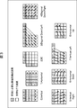
- FIG. 26 is a block diagram illustrating a main configuration example of a personal computer. It is a block diagram which shows the main structural examples of a television receiver. It is a block diagram which shows the main structural examples of a mobile telephone. It is a block diagram which shows the main structural examples of a hard disk recorder. It is a block diagram which shows the main structural examples of a camera.
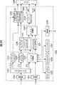
- FIG. 1 shows a configuration of an embodiment of an image encoding apparatus as an image processing apparatus.
- the image encoding device 100 shown in FIG. It is an encoding device that encodes an image using H.264 and MPEG (Moving Picture Experts Group) 4 Part 10 (AVC (Advanced Video Coding)) (hereinafter referred to as H.264 / AVC) format.
- H.264 / AVC Advanced Video Coding
- the image coding apparatus 100 samples (thinned out) and stores adjacent pixels used in intra prediction (intra-screen prediction) by a predetermined method. Then, the image coding apparatus 100 interpolates the sampled adjacent pixels according to a predetermined method, and then uses it for intra prediction.
- the image encoding device 100 includes an A / D (Analog / Digital) conversion unit 101, a screen rearrangement buffer 102, a calculation unit 103, an orthogonal transformation unit 104, a quantization unit 105, and a lossless encoding unit 106. And a storage buffer 107.
- the image coding apparatus 100 includes an inverse quantization unit 108, an inverse orthogonal transform unit 109, and a calculation unit 110.
- the image encoding device 100 includes a deblock filter 111 and a frame memory 112.
- the image encoding device 100 includes an intra prediction unit 114, a motion prediction compensation unit 115, and a selection unit 116.
- the image encoding device 100 includes a rate control unit 117.
- the image encoding device 100 includes a feature amount extraction unit 121, a sampling execution determination unit 122, and a sampling method determination unit 123.
- the A / D conversion unit 101 performs A / D conversion on the input image data, outputs it to the screen rearrangement buffer 102, and stores it.
- the screen rearrangement buffer 102 rearranges the stored frame images in the display order in the order of frames for encoding according to the GOP (Group of Picture) structure.
- the screen rearrangement buffer 102 supplies the image with the rearranged frame order to the arithmetic unit 103, the intra prediction unit 114, and the motion prediction compensation unit 115.
- the calculation unit 103 subtracts the predicted image supplied from the selection unit 116 from the image read from the screen rearrangement buffer 102 and outputs the difference information to the orthogonal transformation unit 104. For example, in the case of an image on which intra coding is performed, the calculation unit 103 adds the predicted image supplied from the intra prediction unit 114 to the image read from the screen rearrangement buffer 102. For example, in the case of an image on which inter coding is performed, the calculation unit 103 adds the predicted image supplied from the motion prediction / compensation unit 115 to the image read from the screen rearrangement buffer 102.
- the orthogonal transform unit 104 performs orthogonal transform such as discrete cosine transform and Karhunen-Loeve transform on the difference information from the operation unit 103 and supplies the transform coefficient to the quantization unit 105.
- the quantization unit 105 quantizes the transform coefficient output from the orthogonal transform unit 104.
- the quantization unit 105 supplies the quantized transform coefficient to the lossless encoding unit 106.
- the lossless encoding unit 106 performs lossless encoding such as variable length encoding and arithmetic encoding on the quantized transform coefficient.
- the lossless encoding unit 106 acquires information indicating intra prediction from the intra prediction unit 114 and acquires information indicating inter prediction mode from the motion prediction compensation unit 115.
- information indicating intra prediction is hereinafter also referred to as intra prediction mode information.
- information indicating an information mode indicating inter prediction is hereinafter also referred to as inter prediction mode information.
- the lossless encoding unit 106 encodes the quantized transform coefficient, and uses a filter coefficient, intra prediction mode information, inter prediction mode information, a quantization parameter, and the like as part of the header information of the encoded data. (Multiplex).
- the lossless encoding unit 106 supplies the encoded data obtained by encoding to the accumulation buffer 107 for accumulation.
- the lossless encoding unit 106 performs lossless encoding processing such as variable length encoding or arithmetic encoding.
- variable length coding examples include H.264.
- CAVLC Context-Adaptive Variable Length Coding
- arithmetic coding examples include CABAC (Context-Adaptive Binary Arithmetic Coding).
- the accumulation buffer 107 temporarily holds the encoded data supplied from the lossless encoding unit 106, and at a predetermined timing, the H.264 buffer stores the encoded data. As an encoded image encoded by the H.264 / AVC format, for example, it is output to a recording device or a transmission path (not shown) in the subsequent stage.
- the transform coefficient quantized by the quantization unit 105 is also supplied to the inverse quantization unit 108.
- the inverse quantization unit 108 inversely quantizes the quantized transform coefficient by a method corresponding to the quantization by the quantization unit 105, and supplies the obtained transform coefficient to the inverse orthogonal transform unit 109.
- the inverse orthogonal transform unit 109 performs inverse orthogonal transform on the supplied transform coefficient by a method corresponding to the orthogonal transform processing by the orthogonal transform unit 104.
- the output subjected to inverse orthogonal transform is supplied to the calculation unit 110.
- the calculation unit 110 adds the prediction image supplied from the selection unit 116 to the inverse orthogonal transformation result supplied from the inverse orthogonal transformation unit 109, that is, the restored difference information, and generates a locally decoded image (decoding Image). For example, when the difference information corresponds to an image on which intra coding is performed, the calculation unit 110 adds the predicted image supplied from the intra prediction unit 114 to the difference information. For example, when the difference information corresponds to an image on which inter coding is performed, the arithmetic unit 110 adds the predicted image supplied from the motion prediction / compensation unit 115 to the difference information.
- the addition result is supplied to the deblocking filter 111 or the intra prediction unit 114.
- the deblock filter 111 removes block distortion of the decoded image by appropriately performing deblock filter processing, and improves image quality by appropriately performing loop filter processing using, for example, a Wiener filter.
- the deblocking filter 111 classifies each pixel and performs an appropriate filter process for each class.
- the deblocking filter 111 supplies the filter processing result to the frame memory 112.
- the frame memory 112 outputs the stored reference image to the motion prediction / compensation unit 115 at a predetermined timing.
- the intra prediction unit 114 performs intra prediction (intra-screen prediction) that generates a predicted image using pixel values in the screen.
- the intra prediction unit 114 performs intra prediction in a plurality of modes (intra prediction modes).
- This intra prediction mode includes a mode for generating a prediction image based on a local decoded image supplied from the calculation unit 110.
- this locally decoded image is an image that has not been subjected to deblocking filter processing.
- the pixel values before the deblocking filter processing of the local decoded image are reconstructed pixels. This is called a value. That is, the reconstructed pixel value is supplied to the intra prediction unit 114.
- a part of the reconstructed pixel value is used as an adjacent pixel value when the intra prediction unit 114 performs prediction processing of another macroblock. More specifically, among the reconstructed pixel values supplied to the intra prediction unit 114 in units of macroblocks, the pixel values of the lowermost pixel row and the rightmost pixel column are used as adjacent pixel values.
- the intra prediction unit 114 holds the pixel values of the bottom pixel row and the rightmost pixel column among the reconstructed pixel values in units of macroblocks supplied from the calculation unit 110.
- the intra prediction unit 114 stores part of the reconstructed pixel values in this way for macroblocks of one row or more (one macroblock line or more).
- the intra prediction unit 114 performs an intra prediction process for the subsequent macroblock while using the stored reconstructed pixel value as an adjacent pixel value.
- a pixel value that is subjected to deblocking filter processing in the deblocking filter 111 on the reconstructed pixel value and stored in the frame memory 112 is referred to as a decoded pixel value.
- This decoded pixel value is supplied to the motion prediction / compensation unit 115 as a reference image.
- the intra prediction unit 114 generates predicted images in all intra prediction modes, evaluates each predicted image, and selects an optimal mode. When the optimal intra prediction mode is selected, the intra prediction unit 114 supplies the prediction image generated in the optimal mode to the calculation unit 103 and the calculation unit 110 via the selection unit 116.
- the intra prediction unit 114 appropriately supplies the intra prediction mode information indicating the adopted intra prediction mode to the lossless encoding unit 106.
- the motion prediction / compensation unit 115 uses the input image supplied from the screen rearrangement buffer 102 and the reference image (decoded pixel value) supplied from the frame memory 112 for the image on which inter coding is performed, as a motion vector. Is calculated. The motion prediction / compensation unit 115 performs motion compensation processing according to the calculated motion vector, and generates a prediction image (inter prediction image information).
- the motion prediction / compensation unit 115 performs inter prediction processing in all candidate inter prediction modes, and generates a prediction image.
- the motion prediction / compensation unit 115 supplies the generated prediction image to the calculation unit 103 and the calculation unit 110 via the selection unit 116.
- the motion prediction / compensation unit 115 supplies inter prediction mode information indicating the adopted inter prediction mode and motion vector information indicating the calculated motion vector to the lossless encoding unit 106.
- the selection unit 116 supplies the output of the intra prediction unit 114 to the calculation unit 103 in the case of an image to be subjected to intra coding, and supplies the output of the motion prediction compensation unit 115 to the calculation unit 103 in the case of an image to be subjected to inter coding. To do.
- the rate control unit 117 controls the quantization operation rate of the quantization unit 105 based on the compressed image stored in the storage buffer 107 so that overflow or underflow does not occur.
- the feature amount extraction unit 121 extracts the feature amount of the image data output from the A / D conversion unit 101. For example, the feature quantity extraction unit 121 identifies at least one of the horizontal size of the image and the vertical size of the macroblock by referring to the header information of the image data or analyzing the actual data.
- the feature content of the image extracted by the feature amount extraction unit 121 is arbitrary.
- the feature amount extraction unit 121 may analyze the content of an image (for example, a texture pattern or complexity) and generate information indicating the content.
- the feature amount extraction unit 121 may specify the picture type (I picture, P picture, or B picture) of the image and the scanning method.
- the feature quantity extraction unit 121 may extract parameters other than these as feature quantities, or may extract a plurality of types of feature quantities.
- the feature amount extraction unit 121 supplies the extracted feature amount (information indicating the feature of the image) to the sampling execution determination unit 122.
- the sampling execution determining unit 122 determines whether or not the intra prediction unit 114 stores (after thinning) the reconstructed pixel value used as the adjacent pixel value according to the supplied image characteristics. Then, control information for controlling whether to sample the reconstructed pixel value is generated. The sampling execution determining unit 122 supplies the generated control information to the sampling method determining unit 123 together with the image feature amount (information indicating the image feature).
- the sampling method determination unit 123 determines whether or not to perform sampling based on the control information, and when sampling is performed, determines the sampling method (sampling method) and generates control information specifying the sampling method. To do.
- the sampling method determination unit 123 supplies the generated various control information and the like to the intra prediction unit 114 together with the image feature amount (information indicating the image feature).
- the intra prediction unit 114 performs sampling of the reconstructed pixel value according to the control information supplied from the sampling method determination unit 123.
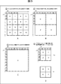
- [Macro block] H In the case of the luminance component, the block division of the coefficient data in the macro block in H.264 / AVC is divided into a block division (4 ⁇ 4 block) in units of 4 ⁇ 4 pixels as shown in FIG. As shown, two types of block division (8 ⁇ 8 blocks) in units of 8 ⁇ 8 pixels are defined. Each square shown in FIG. 2 indicates a block (4 ⁇ 4 block or 8 ⁇ 8 block), and the numbers in the block indicate the order of block scanning in the macroblock. For color difference components, only block division in units of 4 ⁇ 4 pixels is defined.
- FIG. 3 is a diagram for explaining a prediction mode for intra 4 ⁇ 4 prediction, which is intra prediction in units of 4 ⁇ 4 blocks.
- the adjacent reconstructed pixel values of 13 pixels on the left, upper left, upper, and upper right may be used for intra prediction.
- FIG. 4 is a diagram for explaining a prediction mode of intra 8 ⁇ 8 prediction that is intra prediction in units of 8 ⁇ 8 blocks.
- 25 adjacent reconstructed pixels on the left, upper left, upper, and upper right may be used for intra prediction.
- FIG. 5 shows a prediction mode of intra 16 ⁇ 16 prediction, which is intra prediction in units of macroblocks, and adjacent reconstructed pixels used for prediction.
- the 16 ⁇ 16 block macroblock
- the left, upper left, and upper 33 adjacent reconstructed pixels may be used for intra prediction.
- FIG. 6 shows adjacent reconstructed pixels used for intra prediction of color difference components in the case of the color difference format 4: 2: 0.
- pixels indicated by white squares are pixels that perform prediction of processing target macroblocks.
- an image indicated by a gray square is an adjacent pixel (reconstructed pixel) necessary for performing the intra prediction. That is, the intra prediction unit 114 needs to store the pixel values shown in gray in FIGS.
- the data amount of reconstructed pixel values that the intra prediction unit 114 must store may increase.
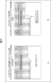
- the processing order of macroblocks other than the macroblock adaptive frame / field encoding process is the raster scan order shown in FIG.
- the processing order of the black block in the macroblock adaptive frame / field encoding process is the order shown in FIG.
- the amount of data of reconstructed pixel values that the intra prediction unit 114 must store may increase depending on the scan method (macroblock processing order).
- the magnitude of the influence of sampling on the decoded image may vary depending on the content of the image (for example, the presence or absence of edges and the complexity of the texture) and the picture type.
- the sampling execution determination unit 122 determines whether to cause the intra prediction unit 114 to sample the reconstructed pixel value to be stored, according to the image characteristics.
- the sampling execution determination unit 122 reconstructs pixels in order to suppress an increase in the amount of data stored in the intra prediction unit 114. It is determined that value sampling is to be executed, and control information indicating that is generated. On the other hand, when the horizontal size of the image is equal to or smaller than the predetermined threshold, the sampling execution determination unit 122 determines that the sampling of the reconstructed pixel value is not performed in order to suppress unnecessary image quality degradation. Control information to be instructed is generated.
- the sampling execution determination unit 122 stores the data stored in the intra prediction unit 114 In order to suppress the increase in the amount, it is determined to perform the sampling of the reconstructed pixel value, and control information indicating that is generated.
- a predetermined threshold for example, in the case of an extended macroblock
- the sampling execution determining unit 122 reconstructs in order to suppress unnecessary image quality degradation. It decides not to execute sampling of pixel values, and generates control information instructing to that effect.
- the sampling execution determination unit 122 performs sampling of the reconstructed pixel value in order to suppress an increase in the amount of data stored in the intra prediction unit 114. And control information for instructing that is generated.
- the sampling execution determination unit 122 determines that the sampling of the reconstructed pixel value is not performed in order to suppress unnecessary image quality degradation. Control information to be instructed is generated.
- the sampling execution determination unit 122 sets the amount of data stored in the intra prediction unit 114. In order to suppress the increase, it is determined that sampling of the reconstructed pixel value is executed, and control information indicating that is generated. Conversely, if the image contains a lot of edge components, the texture is complex, or the texture changes frequently, the sampling execution determination unit 122 suppresses unnecessary image quality degradation based on a predetermined standard. Therefore, it is determined not to perform sampling of the reconstructed pixel value, and control information indicating that is generated.
- the sampling execution determining unit 122 reduces the amount of data stored in the intra prediction unit 114. Then, it is determined that sampling of the reconstructed pixel value is executed, and control information for instructing that is generated. Conversely, when the picture type is an I picture, the sampling execution determination unit 122 determines that the sampling of the reconstructed pixel value is not executed because the visual influence of the sampling on the decoded image is relatively large. Control information for instructing is generated.
- sampling execution determining unit 122 may determine whether or not to execute sampling according to other criteria.
- the sampling method determination unit 123 determines how much the reconstructed pixel value to be stored is sampled by the intra prediction unit 114 according to the feature of the image.
- the sampling method determination unit 123 sets the number of pixels to be sampled so that the increase in the amount of data stored in the intra prediction unit 114 is more suppressed as the horizontal size (horizontal size) of the image to be encoded is larger. It is determined to reduce (increase the number of pixels to be thinned out), and control information indicating that is generated.
- the sampling method determination unit 123 performs sampling so as to suppress the increase in the amount of data stored in the intra prediction unit 114 more strongly as the vertical size of the macroblock (vertical macroblock size) increases. Decrease the number of pixels to be reduced (increase the number of pixels to be thinned out), and generate control information indicating that.
- the sampling method determination unit 123 reduces the number of pixels to be sampled so as to suppress the increase in the data amount stored in the intra prediction unit 114 more strongly ( Control information for instructing to that effect is generated. Conversely, when the macroblock processing order is the raster scan order, the sampling method determination unit 123 increases the number of pixels to be sampled (reduces the number of pixels to be thinned out) so as to suppress unnecessary image quality degradation. And control information for instructing that is generated.
- the sampling method determination unit 123 stores the amount of data stored in the intra prediction unit 114 as the number of edge components included in the image increases, the texture becomes more complex, or the frequency of texture change increases. In order to more strongly suppress the increase in the number of pixels, it is determined to reduce the number of pixels to be sampled (increase the number of pixels to be thinned out), and control information indicating that is generated.
- the sampling method determination unit 123 reduces the number of pixels to be sampled (increases the number of pixels to be thinned out) because the visual influence of sampling on the decoded image is relatively small. Control information for instructing to that effect is generated.
- the sampling method determining unit 123 has a relatively large visual influence on the decoded image, so the number of pixels to be sampled is set so as to suppress unnecessary image quality degradation as much as possible. It is determined to increase (decrease the number of pixels to be thinned out), and control information indicating that is generated.
- sampling method determination unit 123 may determine the degree of sampling in accordance with other criteria.
- sampling method determination unit 123 determines not only the sampling method (thinning degree) but also the interpolation method (method) of the sampled reconstructed pixel value (adjacent pixel value) and specifies the interpolation method. And the control information is supplied to the intra prediction unit 114.
- the intra prediction unit 114 interpolates the thinned pixel values before using the sampled reconstructed pixel values.
- This interpolation method is arbitrary.
- the sampling method determination unit 123 determines an interpolation method according to, for example, the content of the image and the processing capability of the apparatus.
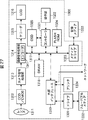
- FIG. 8 is a block diagram illustrating a main configuration example of the intra prediction unit 114 of FIG.
- the intra prediction unit 114 includes a sampling unit 151, a reconstructed pixel storage unit 152, an adjacent pixel reconstruction unit 153, and a predicted image generation unit 154.
- the intra prediction unit 114 further includes a cost function calculation unit 155 and a mode determination unit 156.
- the sampling unit 151 acquires control information indicating whether or not to perform the sampling supplied from the sampling method determining unit 123 and control information indicating the sampling method, and is supplied from the arithmetic unit 110 according to the control information. Among the reconstructed pixel values, sampling (decimation) is performed on pixel values used for processing of the subsequent macroblock as adjacent pixels. The sampling unit 151 reconstructs the reconstructed pixel value sampled based on the control information (reconstructed pixel value thinned out by the sampling unit 151) or the reconstructed pixel value not sampled based on the control information. The data is supplied to the storage unit 152.
- the reconstructed pixel storage unit 152 stores the reconstructed pixel value supplied from the sampling unit 151.
- the adjacent pixel reconstruction unit 153 reads out the pixel value of the adjacent pixel of the processing target macroblock from the reconstruction pixel storage unit 152.
- the adjacent pixel reconstruction unit 153 reads the pixel value using the interpolation method specified by the control information supplied from the sampling method determination unit 123. Interpolation processing is performed on the obtained pixel values, and the thinned pixel values are restored.
- the adjacent pixel reconstruction unit 153 supplies the adjacent pixel value interpolated as necessary in this manner to the predicted image generation unit 154.
- the prediction image generation unit 154 generates a prediction image of the processing target macroblock using the supplied adjacent pixel value, and supplies the prediction image to the cost function calculation unit 155.
- the predicted image generation unit 154 generates predicted images in all intra prediction modes.
- the adjacent pixel reconstruction unit 153 reads out the reconstructed pixel from the reconstruction pixel storage unit 152 as necessary, and supplies it to the predicted image generation unit 154 as an adjacent pixel value.
- the cost function calculation unit 155 calculates a cost function value for each intra prediction mode of 4 ⁇ 4 pixels, 8 ⁇ 8 pixels, and 16 ⁇ 16 pixels with respect to the prediction image generated by the prediction image generation unit 154.
- the cost function value is based on either the High Complexity mode or the Low Complexity mode.
- These modes are H.264. It is defined by JM (Joint Model) which is reference software in the H.264 / AVC format.
- the cost function calculation unit 155 supplies the cost function value calculated as described above to the mode determination unit 156.
- the mode determination unit 156 selects the optimal intra prediction mode based on the supplied cost function value. That is, the mode with the minimum cost function value is selected as the optimum intra prediction mode from among the intra prediction modes.
- the mode determination unit 156 supplies the prediction image of the prediction mode selected as the optimal intra prediction mode to the calculation unit 103 and the calculation unit 110 via the selection unit 116 as necessary. In addition, the mode determination unit 156 supplies the prediction mode information to the lossless encoding unit 106 as necessary.
- the pixels used as adjacent pixels for generating a predicted image for the subsequent macroblock are the bottom pixel row of the macroblock and the rightmost pixel. This is a pixel column.
- a first example of the sampling method is a method of thinning out the lowermost pixel row and the rightmost pixel column of these macroblocks at a rate of one pixel per two pixels (sampling every other pixel).
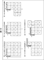
- FIG. 9 shows an example in which the reconstructed pixel sampled by the method of the first example is used as an adjacent pixel.
- White squares shown in FIG. 9 indicate blocks that divide the macroblock. That is, each square represents a block, and the outer frame of the square group represents a macro block to be processed. The numbers inside each square indicate the processing order (block number) within the macroblock.
- a gray square indicates an example of an adjacent pixel used for prediction of a block of block number 0 to be processed first. This adjacent pixel is sampled by the method of the first example described above.
- FIG. 9A shows an example in which the processing target macroblock (luminance component) is intra-predicted in the intra 4 ⁇ 4 prediction mode.
- FIG. 9B shows an example in the case of intra prediction of the processing target macroblock (luminance component) in the intra 8 ⁇ 8 prediction mode.
- C in FIG. 9 illustrates an example in the case of performing intra prediction on the processing target macroblock (luminance component) in the intra 16 ⁇ 16 prediction mode.
- FIG. 9D illustrates an example in the case of intra prediction of a processing target macroblock (color difference component Cb).
- Equation (1) corresponds to A in FIG. 9
- Equation (2) corresponds to B in FIG. 9
- Equation (3) corresponds to C in FIG. 9
- Equation (4) corresponds to D in FIG. Corresponding to
- the adjacent pixel reconstruction unit 153 has a position represented by any one of the equations (1) to (4) according to the intra prediction mode.
- the reconstructed pixel is read from the reconstructed pixel storage unit 152 as an adjacent pixel.
- the adjacent pixel reconstruction unit 153 performs an interpolation process on the read adjacent pixels by, for example, a method as shown in the following expressions (5) to (8).
- any interpolation method other than these may be used as long as the method is determined by the sampling method determination unit 123.
- the bottom pixel row and the rightmost pixel column among the intra prediction results of each block are used as adjacent pixels in the prediction process of the subsequent block.
- the bottom pixel row is used as an adjacent pixel in the intra prediction process of the block of block number 2.
- the rightmost pixel column is used as an adjacent pixel in the intra prediction process of the block of block number 1, for example.
- the sampling unit 151 does not sample (do not thin out) these pixels. .
- a second example of the sampling method is a method in which only the bottom pixel row of these macroblocks is thinned out at a rate of one pixel per two pixels (sampled every other pixel).
- FIG. 10 shows an example in which the reconstructed pixel sampled by the method of the second example is used as an adjacent pixel and the processing target macroblock (luminance component) is intra-predicted in the intra 4 ⁇ 4 prediction mode.
- the position p (x, y) of the reconstructed pixel which is used as an adjacent pixel in the intra prediction of the first block and saved without being thinned out can be expressed as the following Expression (13). .
- adjacent pixels at positions as shown in A of FIG. 10 are used.
- the adjacent pixel arranged in the vertical direction adjacent to the left of the processing target block (block number 0) is a reconstructed pixel of the adjacent macroblock.
- the adjacent pixel reconstruction unit 153 only needs to interpolate only the upper adjacent pixel.
- adjacent pixels at positions as shown in B of FIG. 10 are used. As shown in FIG. 10B, the prediction result of the block of block number 0 is not thinned out. Therefore, the adjacent pixel reconstruction unit 153 only needs to interpolate only the upper adjacent pixel.
- the intra prediction process with the block number 2 is performed as shown in FIG.
- adjacent pixels at positions as shown in FIG. 10C are used. That is, since the bottom row of the prediction result of the block of block number 0 and the bottom pixel row of the prediction result of the block of block number 1 are used as adjacent pixels, these adjacent pixels are thinned out. I can't take it. Similarly to the case of A in FIG. 10, the adjacent pixels arranged in the vertical direction adjacent to the left of the processing target block (the block of block number 2) are not thinned out. Therefore, the adjacent pixel reconstruction unit 153 does not perform interpolation of adjacent pixels.
- FIG. 10D shows an example in the case of intra prediction with block number 4
- E in FIG. 10 shows an example in the case of intra prediction with block number 5.
- the adjacent pixel reconstruction unit 153 since the position of the adjacent pixel is the same as in the case of FIG. 10A or FIG. 10B, the adjacent pixel reconstruction unit 153 only needs to interpolate only the upper adjacent pixel.
- FIG. 11 is a diagram illustrating an example of intra prediction in the intra 8 ⁇ 8 prediction mode.
- prediction when prediction is performed on the block with block number 0, prediction is performed on the block with block number 1 as shown in FIG. As shown in FIG. 11, prediction is performed on the block of block number 2, and finally, prediction is performed on the block of block number 3 as shown in D of FIG. 11.
- the adjacent pixel reconstruction unit 153 interpolates only the upper adjacent pixel.
- the adjacent pixel reconstruction unit 153 does not perform interpolation of adjacent pixels.
- the image coding apparatus 100 reduces the capacity of the memory area or line buffer that stores the bottom line of the macroblock, while the other pixels store the same number of adjacent reconstructed pixels as the conventional method. By doing so, deterioration of image quality can be suppressed.
- a third example of the sampling method is a method of thinning out only the bottom pixel row of the macroblock at a ratio of 3 pixels to 4 pixels (sampling every 3 pixels).
- FIG. 12 shows an example in which the reconstructed pixel sampled by the method of the third example is used as an adjacent pixel.
- FIG. 12A shows an example in which the processing target macroblock (luminance component) is intra-predicted in the intra 4 ⁇ 4 prediction mode.
- B of FIG. 12 shows an example in the case of performing intra prediction on the processing target macroblock (luminance component) in the intra 8 ⁇ 8 prediction mode.
- C in FIG. 12 illustrates an example in the case of performing intra prediction on the processing target macroblock (luminance component) in the intra 16 ⁇ 16 prediction mode.
- Equation (14) corresponds to A in FIG. 12
- Equation (15) corresponds to B in FIG. 12
- Equation (16) corresponds to C in FIG.
- the adjacent pixel reconstruction unit 153 interpolates the adjacent pixels that are thinned out as shown in, for example, the following equations (18) to (25).
- the adjacent pixel reconstruction unit 153 interpolates adjacent pixels by an appropriate method only when the reconstruction pixels stored in the reconstruction pixel storage unit 152 are thinned out.
- the predicted image generation unit 154 can appropriately generate a predicted image regardless of how the reconstructed pixels are sampled.
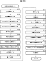
- step S101 the A / D converter 101 performs A / D conversion on the input image.
- step S102 the feature amount extraction unit 121 extracts a feature amount for the A / D converted image.
- step S103 the sampling execution determining unit 122 samples the reconstructed pixel value based on at least one of the horizontal size of the image and the macroblock size in the vertical direction extracted as the feature amount of the image. Determine whether or not.
- the sampling method determination unit 123 extracts at least one of the horizontal size of the image and the macroblock size in the vertical direction extracted as the feature amount of the image. The sampling method is determined based on the above.
- step S105 the screen rearrangement buffer 102 stores the images supplied from the A / D conversion unit 101, and rearranges them from the display order of each picture to the encoding order.
- step S106 the intra prediction unit 114 and the motion prediction / compensation unit 115 each perform image prediction processing. That is, in step S106, the intra prediction unit 114 performs an intra prediction process in the intra prediction mode. The motion prediction / compensation unit 115 performs motion prediction / compensation processing in the inter prediction mode.
- step S107 the selection unit 116 determines the optimal prediction mode based on the cost function values output from the intra prediction unit 114 and the motion prediction compensation unit 115. That is, the selection unit 116 selects either the prediction image generated by the intra prediction unit 114 or the prediction image generated by the motion prediction / compensation unit 115.
- the prediction image selection information is supplied to the intra prediction unit 114 or the motion prediction / compensation unit 115.
- the intra prediction unit 114 supplies information indicating the optimal intra prediction mode (that is, intra prediction mode information) to the lossless encoding unit 106.
- the intra prediction unit 114 supplies the lossless encoding unit 106 with information including the notification that the sampling is performed and the designation of the sampling method and the interpolation method.
- the motion prediction / compensation unit 115 When the prediction image of the optimal inter prediction mode is selected, the motion prediction / compensation unit 115 outputs information indicating the optimal inter prediction mode and, if necessary, information corresponding to the optimal inter prediction mode to the lossless encoding unit 106. To do.
- Information according to the optimal inter prediction mode includes motion vector information, flag information, reference frame information, and the like.
- step S108 the calculation unit 103 calculates a difference between the image rearranged in step S105 and the predicted image obtained by the prediction process in step S106.
- the predicted image is supplied from the motion prediction / compensation unit 115 in the case of inter prediction and from the intra prediction unit 114 in the case of intra prediction to the calculation unit 103 via the selection unit 116.
- the data amount of difference data is reduced compared to the original image data. Therefore, the data amount can be compressed as compared with the case where the image is encoded as it is.
- step S109 the orthogonal transform unit 104 orthogonally transforms the difference information supplied from the calculation unit 103. Specifically, orthogonal transformation such as discrete cosine transformation and Karhunen-Loeve transformation is performed, and transformation coefficients are output.
- step S110 the quantization unit 105 quantizes the transform coefficient.
- step S111 the lossless encoding unit 106 encodes the quantized transform coefficient output from the quantization unit 105. That is, lossless encoding such as variable length encoding or arithmetic encoding is performed on the difference image (secondary difference image in the case of inter).
- the lossless encoding unit 106 encodes information related to the prediction mode of the prediction image selected by the process in step S104, and adds the encoded information to the header information of the encoded data obtained by encoding the difference image.
- the lossless encoding unit 106 encodes the intra prediction mode information supplied from the intra prediction unit 114 or the information corresponding to the optimal inter prediction mode supplied from the motion prediction compensation unit 115, and adds the information to the header information. To do.
- the lossless encoding unit 106 receives notification from the intra prediction unit 114 that sampling is performed, designation of the sampling method or interpolation method, the information is also included in the header information of the encoded data. Append.
- step S112 the accumulation buffer 107 accumulates the encoded data output from the lossless encoding unit 106.
- the encoded data stored in the storage buffer 107 is appropriately read out and transmitted to the decoding side via the transmission path.
- step S113 the rate control unit 117 controls the quantization operation rate of the quantization unit 105 based on the compressed image stored in the storage buffer 107 so that overflow or underflow does not occur.
- step S 110 the difference information quantized by the process of step S110 is locally decoded as follows. That is, in step S ⁇ b> 114, the inverse quantization unit 108 inversely quantizes the transform coefficient quantized by the quantization unit 105 with characteristics corresponding to the characteristics of the quantization unit 105. In step S ⁇ b> 115, the inverse orthogonal transform unit 109 performs inverse orthogonal transform on the transform coefficient inversely quantized by the inverse quantization unit 108 with characteristics corresponding to the characteristics of the orthogonal transform unit 104.
- step S116 the calculation unit 110 adds the prediction image input via the selection unit 116 to the locally decoded difference information, and corresponds to the locally decoded image (corresponding to the input to the calculation unit 103). Image) is generated.
- step S117 the intra prediction unit 114 stores the reconstructed pixel generated in step S116.
- step S118 the deblock filter 111 filters the image output from the calculation unit 110. Thereby, block distortion is removed.
- step S119 the frame memory 112 stores the filtered image.
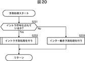
- step S131 the intra prediction unit 114 performs intra prediction on the pixels of the processing target block in all candidate intra prediction modes.
- the processing target image supplied from the screen rearrangement buffer 102 is an image to be inter-processed
- the referenced image is read from the frame memory 112 and supplied to the motion prediction / compensation unit 115.
- the motion prediction / compensation unit 115 Based on these images, in step S132, the motion prediction / compensation unit 115 performs an inter motion prediction process. That is, the motion prediction / compensation unit 115 refers to the image supplied from the frame memory 112 and performs motion prediction processing for all candidate inter prediction modes.
- step S133 the motion prediction / compensation unit 115 determines the prediction mode that gives the minimum value as the optimum inter prediction mode from the cost function values for the inter prediction mode calculated in step S132. Then, the motion prediction / compensation unit 115 supplies the difference between the image to be inter-processed and the secondary difference information generated in the optimal inter prediction mode and the cost function value of the optimal inter prediction mode to the selection unit 116.
- FIG. 15 is a flowchart for explaining an example of the flow of the intra prediction process executed in step S131 of FIG.
- the adjacent pixel reconstruction unit 153 determines an interpolation method in accordance with the designation of the sampling method determination unit 123 in step S151.
- the prediction image generation unit 154 selects a prediction mode to be executed from unprocessed prediction modes.
- the neighboring pixel reconstruction unit 153 reads neighboring pixels from the reconstruction pixel storage unit 152 according to the prediction mode selected in step S152.
- step S154 the adjacent pixel reconstruction unit 153 performs interpolation processing on the read adjacent pixels as necessary, and reconstructs the adjacent pixels used for prediction.
- step S155 the predicted image generation unit 154 generates a predicted image using the adjacent pixels reconstructed in step S154.
- step S156 the prediction image generation unit 154 determines whether or not a prediction image has been generated in all prediction modes. If it is determined that there is a prediction mode in which no prediction image has been generated, the process proceeds to step S152. Return and repeat the subsequent processing.
- the prediction image generation unit 154 generates a prediction image in all prediction modes.
- generation part 154 advances a process to step S157.
- step S157 the cost function calculation unit 155 calculates a cost function value for each prediction mode.
- step S158 the mode determination unit 156 determines an optimal mode for each intra prediction mode based on the cost function value of each mode calculated by the process in step S157.
- step S159 the mode determination unit 156 selects the optimal intra prediction mode based on the cost function value of each mode calculated by the process of step S157.
- the mode determination unit 156 supplies the prediction image generated in the mode selected as the optimal intra prediction mode to the calculation unit 103 and the calculation unit 110.
- the mode determination unit 156 also supplies the lossless encoding unit 106 with information indicating the selected prediction mode, notification that sampling is to be executed, designation of the sampling method and interpolation method, and the like.
- step S159 ends, the intra prediction unit 114 returns the process to FIG. 14 and causes the processes after step S132 to be executed.
- the sampling unit 151 samples the reconstructed pixels to be stored in the reconstructed pixel storage unit 152 based on the notification supplied from the sampling method determining unit 123 in step S171. It is determined whether or not to perform. If it is determined that sampling is to be performed, the sampling unit 151 advances the processing to step S172.
- step S172 the sampling unit 151 determines the sampling method for the reconstructed pixel based on the notification supplied from the sampling method determination unit 123.
- step S173 the sampling unit 151 samples the rightmost and lowermost pixels of the macroblock for the supplied reconstructed pixels for each macroblock.
- step S174 the reconstructed pixel storage unit 152 stores the reconstructed pixels sampled in step S173 (reconstructed pixels remaining after being thinned).
- the intra prediction unit 114 ends the reconstructed pixel storage process, returns the process to step S117 of FIG. 13, and advances the process to step S118.
- step S171 in FIG. 16 If it is determined in step S171 in FIG. 16 that sampling is not performed, the sampling unit 151 advances the processing to step S175.
- step S175 the reconstructed pixel storage unit 152 stores all the pixels at the right end and the lower end of the macroblock among the supplied reconstructed pixels for each macroblock.
- the intra prediction unit 114 ends the reconstructed pixel storage process, returns the process to step S117 of FIG. 13, and advances the process to step S118.
- the image coding apparatus 100 can realize intra-screen prediction with a smaller amount of memory by sampling the reconstructed pixels used for intra prediction. As a result, the image encoding device 100 can realize downsizing of the device, and can also reduce cost and power consumption.
- each block described above is an example, and may be a size other than those described above.
- a designation of a sampling method and an interpolation method, etc. such information is multiplexed with header information of encoded data.
- the information storage location is arbitrary.
- these pieces of information may be stored in a parameter set (for example, a sequence or a picture header) such as SEI (Suplemental / Enhancement / Information). These pieces of information may be transmitted from the image encoding device to the image decoding device separately from the encoded data (as a separate file).
- control of whether or not to perform sampling and the control of the method may be performed for each arbitrary processing unit. For example, it may be performed for each picture unit or may be performed for each sequence unit. Of course, it may be performed for each processing unit other than these.
- Second Embodiment> [Image decoding device] The encoded data encoded by the image encoding device 100 described in the first embodiment is transmitted to an image decoding device corresponding to the image encoding device 100 via a predetermined transmission path and decoded. .
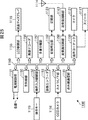
- FIG. 17 is a block diagram illustrating a main configuration example of an image decoding device.
- the image decoding apparatus 200 includes a storage buffer 201, a lossless decoding unit 202, an inverse quantization unit 203, an inverse orthogonal transform unit 204, a calculation unit 205, a deblock filter 206, a screen rearrangement buffer 207, And a D / A converter 208.
- the image decoding apparatus 200 further includes a frame memory 209, an intra prediction unit 211, a motion prediction / compensation unit 212, and a selection unit 213.
- the accumulation buffer 201 accumulates the transmitted encoded data. This encoded data is encoded by the image encoding device 100.
- the lossless decoding unit 202 decodes the encoded data read from the accumulation buffer 201 at a predetermined timing by a method corresponding to the encoding method of the lossless encoding unit 106 in FIG.
- the inverse quantization unit 203 inversely quantizes the coefficient data obtained by decoding by the lossless decoding unit 202 by a method corresponding to the quantization method of the quantization unit 105 in FIG.
- the inverse quantization unit 203 supplies the inversely quantized coefficient data to the inverse orthogonal transform unit 204.
- the inverse orthogonal transform unit 204 is a method corresponding to the orthogonal transform method of the orthogonal transform unit 104 in FIG. 1, performs inverse orthogonal transform on the coefficient data, and corresponds to the residual data before being orthogonally transformed in the image encoding device 100. Decoding residual data to be obtained is obtained.
- the decoded residual data obtained by the inverse orthogonal transform is supplied to the calculation unit 205. Further, a prediction image is supplied from the intra prediction unit 211 or the motion prediction compensation unit 212 to the calculation unit 205 via the selection unit 213.
- the calculation unit 205 adds the decoded residual data and the prediction image, and obtains decoded image data corresponding to the image data before the prediction image is subtracted by the calculation unit 103 of the image encoding device 100.
- the calculation unit 205 supplies the decoded image data to the intra prediction unit 211 and the deblock filter 206.
- the deblocking filter 206 removes the block distortion of the decoded image, supplies it to the frame memory 209, stores it, and also supplies it to the screen rearrangement buffer 207.
- the screen rearrangement buffer 207 rearranges images. That is, the order of frames rearranged for the encoding order by the screen rearrangement buffer 102 in FIG. 1 is rearranged in the original display order.
- the D / A conversion unit 208 D / A converts the image supplied from the screen rearrangement buffer 207, outputs it to a display (not shown), and displays it.
- the intra-prediction unit 211 is appropriately supplied with information indicating the intra-prediction mode obtained by decoding the header information, notification that sampling is performed, designation of the sampling method and interpolation method, and the like from the lossless decoding unit 202 as appropriate.
- the motion prediction / compensation unit 212 acquires information (prediction mode information, motion vector information, reference frame information) obtained by decoding the header information from the lossless decoding unit 202.
- information indicating the inter prediction mode is supplied, the motion prediction / compensation unit 212 acquires a reference image from the frame memory 209 based on the inter motion vector information from the lossless decoding unit 202, and the reference image and motion vector information are obtained.
- the prediction image is generated using the prediction image, and the generated prediction image is supplied to the selection unit 213.
- the selection unit 213 selects the prediction image generated by the motion prediction / compensation unit 212 or the intra prediction unit 211 and supplies the selected prediction image to the calculation unit 205.
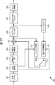
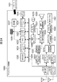
- FIG. 18 is a block diagram illustrating a main configuration example of the intra prediction unit 211 of FIG.
- the intra prediction unit 211 includes a control unit 231, a sampling unit 232, a reconstruction pixel storage unit 233, an adjacent pixel reconstruction unit 234, and a predicted image generation unit 235.
- the control unit 231 controls each unit of the sampling unit 232 to the predicted image generation unit 235. As in the case of the intra prediction unit 114 of the image coding apparatus 100, the reconfiguration pixel sampling and interpolation are executed.
- the sampling unit 232 has basically the same configuration as the sampling unit 151 and basically performs the same processing. That is, the sampling unit 232 performs sampling on the reconstructed pixels supplied from the calculation unit 205 as necessary under the control of the control unit 231, and the sampled reconstructed pixel values (the sampling unit 232 thins out and remains). Reconstructed pixel values) or reconstructed pixel values not sampled based on the control information are supplied to the reconstructed pixel storage unit 233.
- the reconstruction pixel storage unit 233 basically has the same configuration as the reconstruction pixel storage unit 152 and performs the same processing. That is, the reconstructed pixel storage unit 233 is controlled by the control unit 231 and stores the reconstructed pixel value supplied from the sampling unit 232.
- the adjacent pixel reconstruction unit 234 basically has the same configuration as the adjacent pixel reconstruction unit 153 and performs the same processing. That is, the adjacent pixel reconstruction unit 234 is controlled by the control unit 231, and reads the pixel value of the adjacent pixel of the processing target macroblock from the reconstruction pixel storage unit 233. When the read pixel value is sampled by the sampling unit 232, the adjacent pixel reconstruction unit 234 reads the pixel value by the interpolation method specified by the control information supplied via the control unit 231. Interpolation processing is performed on the obtained pixel values, and the thinned pixel values are restored. The adjacent pixel reconstruction unit 234 supplies the adjacent pixel value interpolated as necessary to the predicted image generation unit 235 in this way.
- the predicted image generation unit 235 basically has the same configuration as the predicted image generation unit 154, and performs the same processing. That is, the prediction image generation unit 235 is controlled by the control unit 231 to generate a prediction image of the processing target macroblock using the adjacent pixel value supplied from the adjacent pixel reconstruction unit 234, and the prediction image is calculated by the calculation unit. 205.
- the predicted image generation unit 235 generates predicted images in this way in all intra prediction modes.
- the adjacent pixel reconstruction unit 234 reads the reconstructed pixel from the reconstruction pixel storage unit 233 as necessary, and supplies it to the predicted image generation unit 235 as an adjacent pixel value.
- the intra prediction unit 211 of the image decoding device 200 performs the same intra prediction as the intra prediction unit 114 of the image encoding device 100, but the intra prediction unit 211 is the same as the case of the intra prediction unit 114. If necessary, sampling (decimation) is performed on the reconstructed pixels used as adjacent pixels in the intra prediction.
- the intra prediction unit 211 of the image decoding device 200 performs image coding based on information provided from the image coding device 100, such as notification that sampling is performed, designation of a sampling method and an interpolation method, and the like. Sampling and interpolation similar to those performed in the apparatus 100 are performed. Thereby, the image decoding apparatus 200 can reduce the amount of memory required for intra prediction.
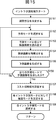
- step S201 the accumulation buffer 201 accumulates the transmitted encoded data.
- step S202 the lossless decoding unit 202 decodes the encoded data supplied from the accumulation buffer 201. That is, the I picture, P picture, and B picture encoded by the lossless encoding unit 106 in FIG. 1 are decoded.
- motion vector information reference frame information
- prediction mode information intra prediction mode or inter prediction mode
- flag information notification that sampling is executed, designation of sampling method and interpolation method, and the like are also decoded.
- the prediction mode information is intra prediction mode information
- the prediction mode information is supplied to the intra prediction unit 211.
- the prediction mode information is inter prediction mode information
- motion vector information corresponding to the prediction mode information is supplied to the motion prediction / compensation unit 212.
- information indicating that sampling is executed and information such as the designation of the sampling method and the interpolation method are supplied to the intra prediction unit 211.
- step S203 the inverse quantization unit 203 inversely quantizes the transform coefficient decoded by the lossless decoding unit 202 with characteristics corresponding to the characteristics of the quantization unit 105 in FIG.
- step S204 the inverse orthogonal transform unit 204 performs inverse orthogonal transform on the transform coefficient inversely quantized by the inverse quantization unit 203 with characteristics corresponding to the characteristics of the orthogonal transform unit 104 in FIG.
- the difference information corresponding to the input of the orthogonal transform unit 104 (output of the calculation unit 103) in FIG. 1 is decoded.
- step S205 the intra prediction unit 211 or the motion prediction / compensation unit 212 performs image prediction processing corresponding to the prediction mode information supplied from the lossless decoding unit 202, respectively.
- the intra prediction unit 211 when the intra prediction mode information is supplied from the lossless decoding unit 202, the intra prediction unit 211 performs an intra prediction process in the intra prediction mode. In addition, when the lossless decoding unit 202 receives notification that sampling is performed, designation of a sampling method or an interpolation method, the intra prediction unit 211 performs intra prediction processing (reconstructed pixel of the reconstructed pixel) using the information. In-screen prediction with sampling and interpolation processing).
- the motion prediction / compensation unit 212 When the inter prediction mode information is supplied from the lossless decoding unit 202, the motion prediction / compensation unit 212 performs a motion prediction process in the inter prediction mode.
- step S206 the selection unit 213 selects a predicted image. That is, the prediction image generated by the intra prediction unit 211 or the prediction image generated by the motion prediction compensation unit 212 is supplied to the selection unit 213. The selection unit 213 selects one of them. The selected prediction image is supplied to the calculation unit 205.
- step S207 the calculation unit 205 adds the predicted image selected by the process of step S206 to the difference information obtained by the process of step S204. As a result, the original image data is restored.
- step S208 the intra prediction unit 211 stores the reconstructed pixel that is the image data restored in step S207.
- step S209 the deblock filter 206 filters the decoded image data supplied from the calculation unit 205. Thereby, block distortion is removed.
- step S210 the frame memory 209 stores the filtered decoded image data.
- step S211 the screen rearrangement buffer 207 rearranges the frames of the decoded image data. That is, the order of frames of the decoded image data rearranged for encoding by the screen rearrangement buffer 102 (FIG. 1) of the image encoding device 100 is rearranged to the original display order.
- step S212 the D / A converter 208 D / A converts the decoded image data in which the frames are rearranged in the screen rearrangement buffer 207.
- the decoded image data is output to a display (not shown), and the image is displayed.
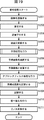
- the lossless decoding unit 202 determines whether or not intra coding is performed based on the intra prediction mode information. If it is determined that intra coding has been performed, the lossless decoding unit 202 supplies the intra prediction mode information to the intra prediction unit 211, and the process proceeds to step S232. Note that, when there is a notification that sampling is executed, a designation of a sampling method or an interpolation method, the lossless decoding unit 202 also supplies the information to the intra prediction unit 211.
- step S232 the intra prediction unit 211 performs an intra prediction process.
- the image decoding apparatus 200 returns the process to step S205 in FIG. 19 to execute the processes after step S206.
- step S231 when it is determined in step S231 that inter coding has been performed, the lossless decoding unit 202 supplies inter prediction mode information to the motion prediction / compensation unit 212, and the process proceeds to step S233.
- step S233 the motion prediction / compensation unit 212 performs inter motion prediction / compensation processing.
- the image decoding apparatus 200 returns the process to step S205 in FIG. 19 to execute the processes after step S206.
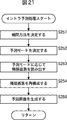
- the adjacent pixel reconstruction unit 234 determines an interpolation method according to the control of the control unit 231.
- the predicted image generation unit 235 determines the prediction mode according to the control of the control unit 231.
- the adjacent pixel reconstruction unit 234 reads out adjacent pixels according to the prediction mode determined in step S252.
- step S254 the adjacent pixel reconstruction unit 234 reconstructs adjacent pixels according to the interpolation method determined in step S251.
- the predicted image generation unit 235 generates a predicted image using the reconstructed adjacent pixels.
- control unit 231 ends the intra prediction process, returns the process to step S232 of FIG. 20, and performs the subsequent processes.
- step S208 in FIG. 19 Note that the reconstructed pixel storage process executed in step S208 in FIG. 19 is performed in the same way as in the case shown in the flowchart in FIG.
- the image decoding apparatus 200 can reduce the amount of memory necessary for intra prediction.
- Hadamard transform or the like may be used instead of the orthogonal transform or inverse orthogonal transform described above.
- size of each block demonstrated above is an example.
- information indicating whether or not sampling is performed in the image encoding device 100 and information indicating the sampling method and interpolation method performed in the image encoding device 100 are transmitted from the image encoding device 100 to the image decoding device 200. It has been described that the image decoding apparatus 200 performs the same sampling and interpolation processing as the image encoding apparatus 100 based on such information. However, the present invention is not limited to this, and the image decoding device 200 may extract image feature amounts in the same manner as the image encoding device 100, and perform sampling and interpolation processing based on the extracted feature amounts.
- the image decoding apparatus 200 may extract the feature amount of the image from the header information or the like of the encoded data, or may analyze the decoded image data and extract the feature amount.
- Micro block In the above, a macro block of 16 ⁇ 16 or less has been described, but the size of the macro block may be larger than 16 ⁇ 16.
- This technique can be applied to macroblocks of any size as shown in FIG. 22, for example.
- the present technology can be applied not only to a normal macroblock such as 16 ⁇ 16 pixels but also to an extended macroblock (extended macroblock) such as 32 ⁇ 32 pixels.
- a macro block composed of 32 ⁇ 32 pixels divided into blocks (partitions) of 32 ⁇ 32 pixels, 32 ⁇ 16 pixels, 16 ⁇ 32 pixels, and 16 ⁇ 16 pixels.
- blocks from 16 ⁇ 16 pixels divided into blocks of 16 ⁇ 16 pixels, 16 ⁇ 8 pixels, 8 ⁇ 16 pixels, and 8 ⁇ 8 pixels are sequentially shown from the left.
- an 8 ⁇ 8 pixel block divided into 8 ⁇ 8 pixel, 8 ⁇ 4 pixel, 4 ⁇ 8 pixel, and 4 ⁇ 4 pixel blocks is sequentially shown.
- the 32 ⁇ 32 pixel macroblock can be processed in the 32 ⁇ 32 pixel, 32 ⁇ 16 pixel, 16 ⁇ 32 pixel, and 16 ⁇ 16 pixel blocks shown in the upper part.
- the 16 ⁇ 16 pixel block shown on the right side of the upper row is H.264. Similar to the H.264 / AVC format, processing in blocks of 16 ⁇ 16 pixels, 16 ⁇ 8 pixels, 8 ⁇ 16 pixels, and 8 ⁇ 8 pixels shown in the middle stage is possible.
- the 8 ⁇ 8 pixel block shown on the right side of the middle row Similar to the H.264 / AVC format, processing in blocks of 8 ⁇ 8 pixels, 8 ⁇ 4 pixels, 4 ⁇ 8 pixels, and 4 ⁇ 4 pixels shown in the lower stage is possible.
- the block of 32 ⁇ 32 pixels, 32 ⁇ 16 pixels, and 16 ⁇ 32 pixels shown in the upper part of FIG. 20 is referred to as a first layer.
- the 16 ⁇ 16 pixel block shown on the right side of the upper stage and the 16 ⁇ 16 pixel, 16 ⁇ 8 pixel, and 8 ⁇ 16 pixel blocks shown in the middle stage are referred to as a second hierarchy.
- the 8 ⁇ 8 pixel block shown on the right side of the middle row and the 8 ⁇ 8 pixel, 8 ⁇ 4 pixel, 4 ⁇ 8 pixel, and 4 ⁇ 4 pixel blocks shown on the lower row are referred to as a third hierarchy.
- H. Larger blocks can be defined as a superset while maintaining compatibility with the H.264 / AVC format.
- the CPU 501 of the personal computer 500 executes various processes in accordance with a program stored in a ROM (Read Only Memory) 502 or a program loaded from a storage unit 513 into a RAM (Random Access Memory) 503.
- the RAM 503 also appropriately stores data necessary for the CPU 501 to execute various processes.
- the CPU 501, the ROM 502, and the RAM 503 are connected to each other via a bus 504.
- An input / output interface 510 is also connected to the bus 504.
- the input / output interface 510 includes an input unit 511 including a keyboard and a mouse, a display including a CRT (Cathode Ray Tube) and an LCD (Liquid Crystal Display), an output unit 512 including a speaker, and a hard disk.
- a communication unit 514 including a storage unit 513 and a modem is connected. The communication unit 514 performs communication processing via a network including the Internet.
- a drive 515 is connected to the input / output interface 510 as necessary, and a removable medium 521 such as a magnetic disk, an optical disk, a magneto-optical disk, or a semiconductor memory is appropriately mounted, and a computer program read from them is It is installed in the storage unit 513 as necessary.
- a removable medium 521 such as a magnetic disk, an optical disk, a magneto-optical disk, or a semiconductor memory is appropriately mounted, and a computer program read from them is It is installed in the storage unit 513 as necessary.
- a program constituting the software is installed from a network or a recording medium.
- the recording medium is distributed to distribute the program to the user separately from the apparatus main body, and includes a magnetic disk (including a flexible disk) on which the program is recorded, an optical disk ( It only consists of removable media 521 consisting of CD-ROM (compact disc-read only memory), DVD (including digital Versatile disc), magneto-optical disk (including MD (mini disc)), or semiconductor memory. Rather, it is composed of a ROM 502 on which a program is recorded and a hard disk included in the storage unit 513, which is distributed to the user in a state of being pre-installed in the apparatus main body.
- a magnetic disk including a flexible disk
- an optical disk It only consists of removable media 521 consisting of CD-ROM (compact disc-read only memory), DVD (including digital Versatile disc), magneto-optical disk (including MD (mini disc)), or semiconductor memory. Rather, it is composed of a ROM 502 on which a program is recorded and a hard disk included in the storage unit 513, which is distributed to
- the program executed by the computer may be a program that is processed in time series in the order described in this specification, or in parallel or at a necessary timing such as when a call is made. It may be a program for processing.
- the step of describing the program recorded on the recording medium is not limited to the processing performed in chronological order according to the described order, but may be performed in parallel or It also includes processes that are executed individually.
- system represents the entire apparatus composed of a plurality of devices (apparatuses).
- the configuration described as one device (or processing unit) may be divided and configured as a plurality of devices (or processing units).
- the configurations described above as a plurality of devices (or processing units) may be combined into a single device (or processing unit).
- a configuration other than that described above may be added to the configuration of each device (or each processing unit).
- a part of the configuration of a certain device (or processing unit) may be included in the configuration of another device (or other processing unit).
- image encoding device 100 and image decoding device 200 can be applied to any electronic device. Examples thereof will be described below.
- FIG. 24 is a block diagram illustrating a main configuration example of a television receiver using the image decoding device 200.
- a terrestrial tuner 1013 has a terrestrial tuner 1013, a video decoder 1015, a video signal processing circuit 1018, a graphic generation circuit 1019, a panel drive circuit 1020, and a display panel 1021.
- the terrestrial tuner 1013 receives a broadcast wave signal of terrestrial analog broadcast via an antenna, demodulates it, acquires a video signal, and supplies it to the video decoder 1015.
- the video decoder 1015 performs a decoding process on the video signal supplied from the terrestrial tuner 1013 and supplies the obtained digital component signal to the video signal processing circuit 1018.
- the video signal processing circuit 1018 performs predetermined processing such as noise removal on the video data supplied from the video decoder 1015 and supplies the obtained video data to the graphic generation circuit 1019.
- the graphic generation circuit 1019 generates video data of a program to be displayed on the display panel 1021, image data by processing based on an application supplied via a network, and the generated video data and image data to the panel drive circuit 1020. Supply.
- the graphic generation circuit 1019 generates video data (graphics) for displaying a screen used by the user for selecting an item and superimposing it on the video data of the program.
- a process of supplying data to the panel drive circuit 1020 is also appropriately performed.
- the panel drive circuit 1020 drives the display panel 1021 based on the data supplied from the graphic generation circuit 1019, and causes the display panel 1021 to display the video of the program and the various screens described above.
- the display panel 1021 is composed of an LCD (Liquid Crystal Display) or the like, and displays a program video or the like according to control by the panel drive circuit 1020.
- LCD Liquid Crystal Display
- the television receiver 1000 also includes an audio A / D (Analog / Digital) conversion circuit 1014, an audio signal processing circuit 1022, an echo cancellation / audio synthesis circuit 1023, an audio amplification circuit 1024, and a speaker 1025.
- an audio A / D (Analog / Digital) conversion circuit 1014 An audio signal processing circuit 1022, an echo cancellation / audio synthesis circuit 1023, an audio amplification circuit 1024, and a speaker 1025.
- the terrestrial tuner 1013 acquires not only the video signal but also the audio signal by demodulating the received broadcast wave signal.
- the terrestrial tuner 1013 supplies the acquired audio signal to the audio A / D conversion circuit 1014.
- the audio A / D conversion circuit 1014 performs A / D conversion processing on the audio signal supplied from the terrestrial tuner 1013, and supplies the obtained digital audio signal to the audio signal processing circuit 1022.
- the audio signal processing circuit 1022 performs predetermined processing such as noise removal on the audio data supplied from the audio A / D conversion circuit 1014 and supplies the obtained audio data to the echo cancellation / audio synthesis circuit 1023.
- the echo cancellation / voice synthesis circuit 1023 supplies the voice data supplied from the voice signal processing circuit 1022 to the voice amplification circuit 1024.
- the audio amplification circuit 1024 performs D / A conversion processing and amplification processing on the audio data supplied from the echo cancellation / audio synthesis circuit 1023, adjusts to a predetermined volume, and then outputs the audio from the speaker 1025.
- the television receiver 1000 also has a digital tuner 1016 and an MPEG decoder 1017.
- the digital tuner 1016 receives a broadcast wave signal of digital broadcasting (terrestrial digital broadcasting, BS (Broadcasting Satellite) / CS (Communications Satellite) digital broadcasting) via an antenna, demodulates, and MPEG-TS (Moving Picture Experts Group). -Transport Stream) and supply it to the MPEG decoder 1017.
- digital broadcasting terrestrial digital broadcasting, BS (Broadcasting Satellite) / CS (Communications Satellite) digital broadcasting
- MPEG-TS Motion Picture Experts Group
- the MPEG decoder 1017 releases the scramble applied to the MPEG-TS supplied from the digital tuner 1016 and extracts a stream including program data to be played (viewing target).
- the MPEG decoder 1017 decodes the audio packet constituting the extracted stream, supplies the obtained audio data to the audio signal processing circuit 1022, decodes the video packet constituting the stream, and converts the obtained video data into the video This is supplied to the signal processing circuit 1018.
- the MPEG decoder 1017 supplies EPG (Electronic Program Guide) data extracted from the MPEG-TS to the CPU 1032 via a path (not shown).
- EPG Electronic Program Guide
- the television receiver 1000 uses the above-described image decoding device 200 as the MPEG decoder 1017 for decoding video packets in this way.
- MPEG-TS transmitted from a broadcasting station or the like is encoded by the image encoding device 100.
- the MPEG decoder 1017 is sampled at the broadcast station (image encoding device 100) extracted from the encoded data supplied from the broadcast station (image encoding device 100). Using information such as notification of rejection and designation of sampling method and interpolation method, sampling of neighboring pixels and interpolation processing are performed as necessary, a predicted image is generated using the neighboring pixels, and the predicted image is used. Then, decoded image data is generated from the residual information. Accordingly, the MPEG decoder 1017 can reduce the amount of memory necessary for intra prediction.
- the video data supplied from the MPEG decoder 1017 is subjected to predetermined processing in the video signal processing circuit 1018 as in the case of the video data supplied from the video decoder 1015, and the generated video data in the graphic generation circuit 1019. Are appropriately superimposed and supplied to the display panel 1021 via the panel drive circuit 1020, and the image is displayed.
- the audio data supplied from the MPEG decoder 1017 is subjected to predetermined processing in the audio signal processing circuit 1022 as in the case of the audio data supplied from the audio A / D conversion circuit 1014, and an echo cancellation / audio synthesis circuit 1023.
- predetermined processing in the audio signal processing circuit 1022 as in the case of the audio data supplied from the audio A / D conversion circuit 1014, and an echo cancellation / audio synthesis circuit 1023.
- sound adjusted to a predetermined volume is output from the speaker 1025.
- the television receiver 1000 also includes a microphone 1026 and an A / D conversion circuit 1027.
- the A / D conversion circuit 1027 receives a user's voice signal captured by a microphone 1026 provided in the television receiver 1000 for voice conversation, and performs A / D conversion processing on the received voice signal.
- the obtained digital audio data is supplied to the echo cancellation / audio synthesis circuit 1023.
- the echo cancellation / audio synthesis circuit 1023 performs echo cancellation on the audio data of the user A.
- the voice data obtained by combining with other voice data is output from the speaker 1025 via the voice amplifier circuit 1024.
- the television receiver 1000 also includes an audio codec 1028, an internal bus 1029, an SDRAM (Synchronous Dynamic Random Access Memory) 1030, a flash memory 1031, a CPU 1032, a USB (Universal Serial Bus) I / F 1033, and a network I / F 1034.
- an audio codec 1028 an internal bus 1029
- an SDRAM Serial Dynamic Random Access Memory
- flash memory 1031
- CPU central processing unit
- USB Universal Serial Bus
- the A / D conversion circuit 1027 receives a user's voice signal captured by a microphone 1026 provided in the television receiver 1000 for voice conversation, and performs A / D conversion processing on the received voice signal.
- the obtained digital audio data is supplied to the audio codec 1028.
- the audio codec 1028 converts the audio data supplied from the A / D conversion circuit 1027 into data of a predetermined format for transmission via the network, and supplies the data to the network I / F 1034 via the internal bus 1029.
- the network I / F 1034 is connected to the network via a cable attached to the network terminal 1035.
- the network I / F 1034 transmits the audio data supplied from the audio codec 1028 to another device connected to the network.
- the network I / F 1034 receives, for example, audio data transmitted from another device connected via the network via the network terminal 1035, and receives the audio data via the internal bus 1029 to the audio codec 1028. Supply.
- the voice codec 1028 converts the voice data supplied from the network I / F 1034 into data of a predetermined format and supplies it to the echo cancellation / voice synthesis circuit 1023.
- the echo cancellation / speech synthesis circuit 1023 performs echo cancellation on the speech data supplied from the speech codec 1028, and synthesizes speech data obtained by combining with other speech data via the speech amplification circuit 1024. And output from the speaker 1025.
- the SDRAM 1030 stores various data necessary for the CPU 1032 to perform processing.
- the flash memory 1031 stores a program executed by the CPU 1032.
- the program stored in the flash memory 1031 is read by the CPU 1032 at a predetermined timing such as when the television receiver 1000 is activated.
- the flash memory 1031 also stores EPG data acquired via digital broadcasting, data acquired from a predetermined server via a network, and the like.
- the flash memory 1031 stores MPEG-TS including content data acquired from a predetermined server via a network under the control of the CPU 1032.
- the flash memory 1031 supplies the MPEG-TS to the MPEG decoder 1017 via the internal bus 1029, for example, under the control of the CPU 1032.
- the MPEG decoder 1017 processes the MPEG-TS as in the case of MPEG-TS supplied from the digital tuner 1016. In this way, the television receiver 1000 receives content data including video and audio via the network, decodes it using the MPEG decoder 1017, displays the video, and outputs audio. Can do.
- the television receiver 1000 also includes a light receiving unit 1037 that receives an infrared signal transmitted from the remote controller 1051.
- the light receiving unit 1037 receives infrared rays from the remote controller 1051 and outputs a control code representing the contents of the user operation obtained by demodulation to the CPU 1032.
- the CPU 1032 executes a program stored in the flash memory 1031 and controls the entire operation of the television receiver 1000 according to a control code supplied from the light receiving unit 1037.
- the CPU 1032 and each part of the television receiver 1000 are connected via a path (not shown).
- the USB I / F 1033 transmits / receives data to / from an external device of the television receiver 1000 connected via a USB cable attached to the USB terminal 1036.
- the network I / F 1034 is connected to the network via a cable attached to the network terminal 1035, and transmits / receives data other than audio data to / from various devices connected to the network.
- the television receiver 1000 can reduce the amount of memory necessary for in-screen prediction by using the image decoding device 200 as the MPEG decoder 1017. As a result, the television receiver 1000 can reduce the amount of memory necessary for in-screen prediction of broadcast wave signals received via an antenna and content data acquired via a network, and more real-time processing can be performed. It can be realized at a low cost.
- FIG. 25 is a block diagram illustrating a main configuration example of a mobile phone using the image encoding device 100 and the image decoding device 200.
- a cellular phone 1100 shown in FIG. 25 includes a main control unit 1150, a power supply circuit unit 1151, an operation input control unit 1152, an image encoder 1153, a camera I / F unit 1154, an LCD control, which are configured to control each unit in an integrated manner.
- Section 1155, image decoder 1156, demultiplexing section 1157, recording / reproducing section 1162, modulation / demodulation circuit section 1158, and audio codec 1159 are connected to each other via a bus 1160.
- the mobile phone 1100 also includes operation keys 1119, a CCD (Charge Coupled Devices) camera 1116, a liquid crystal display 1118, a storage unit 1123, a transmission / reception circuit unit 1163, an antenna 1114, a microphone (microphone) 1121, and a speaker 1117.
- a CCD Charge Coupled Devices
- the power supply circuit unit 1151 starts up the mobile phone 1100 in an operable state by supplying power from the battery pack to each unit.
- the mobile phone 1100 transmits and receives voice signals, e-mails and image data, and images in various modes such as a voice call mode and a data communication mode based on the control of the main control unit 1150 including a CPU, a ROM, a RAM, and the like. Various operations such as shooting or data recording are performed.
- the mobile phone 1100 converts the voice signal collected by the microphone (microphone) 1121 into digital voice data by the voice codec 1159, performs spectrum spread processing by the modulation / demodulation circuit unit 1158, and transmits and receives
- the unit 1163 performs digital / analog conversion processing and frequency conversion processing.
- the cellular phone 1100 transmits the transmission signal obtained by the conversion process to a base station (not shown) via the antenna 1114.
- the transmission signal (voice signal) transmitted to the base station is supplied to the mobile phone of the other party via the public telephone line network.
- the cellular phone 1100 in the voice call mode, the cellular phone 1100 amplifies the received signal received by the antenna 1114 by the transmission / reception circuit unit 1163, further performs frequency conversion processing and analog-digital conversion processing, and performs spectrum despreading processing by the modulation / demodulation circuit unit 1158. Then, the audio codec 1159 converts it into an analog audio signal. The cellular phone 1100 outputs an analog audio signal obtained by the conversion from the speaker 1117.
- the mobile phone 1100 when transmitting an e-mail in the data communication mode, receives the text data of the e-mail input by operating the operation key 1119 in the operation input control unit 1152.
- the cellular phone 1100 processes the text data in the main control unit 1150 and displays it on the liquid crystal display 1118 as an image via the LCD control unit 1155.
- the mobile phone 1100 generates e-mail data in the main control unit 1150 based on text data received by the operation input control unit 1152, user instructions, and the like.
- the cellular phone 1100 performs spread spectrum processing on the e-mail data by the modulation / demodulation circuit unit 1158 and digital / analog conversion processing and frequency conversion processing by the transmission / reception circuit unit 1163.
- the cellular phone 1100 transmits the transmission signal obtained by the conversion process to a base station (not shown) via the antenna 1114.
- the transmission signal (e-mail) transmitted to the base station is supplied to a predetermined destination via a network and a mail server.
- the mobile phone 1100 when receiving an e-mail in the data communication mode, receives and amplifies the signal transmitted from the base station by the transmission / reception circuit unit 1163 via the antenna 1114, and further performs frequency conversion processing and Analog-digital conversion processing.
- the cellular phone 1100 performs spectrum despreading processing on the received signal by the modulation / demodulation circuit unit 1158 to restore the original e-mail data.
- the cellular phone 1100 displays the restored e-mail data on the liquid crystal display 1118 via the LCD control unit 1155.
- the mobile phone 1100 can also record (store) the received e-mail data in the storage unit 1123 via the recording / playback unit 1162.
- the storage unit 1123 is an arbitrary rewritable storage medium.
- the storage unit 1123 may be, for example, a semiconductor memory such as a RAM or a built-in flash memory, a hard disk, or a removable disk such as a magnetic disk, a magneto-optical disk, an optical disk, a USB memory, or a memory card. It may be media. Of course, other than these may be used.
- the mobile phone 1100 when transmitting image data in the data communication mode, the mobile phone 1100 generates image data with the CCD camera 1116 by imaging.
- the CCD camera 1116 has an optical device such as a lens and a diaphragm and a CCD as a photoelectric conversion element, images a subject, converts the intensity of received light into an electrical signal, and generates image data of the subject image.
- the CCD camera 1116 encodes the image data with the image encoder 1153 via the camera I / F unit 1154 and converts the encoded image data into encoded image data.
- the cellular phone 1100 uses the above-described image encoding device 100 as the image encoder 1153 that performs such processing. Similar to the case of the image encoding device 100, the image encoder 1153 determines whether or not to perform sampling of adjacent pixels based on the feature amount extracted from the image data, and if so, the sampling method and the interpolation processing method. Determination is performed, and adjacent pixels are sampled and stored as necessary. When performing the intra prediction, the image encoder 1153 reads the adjacent pixels, performs interpolation processing as necessary, and reconstructs the adjacent pixels. Then, the image encoder 1153 generates a predicted image using the reconstructed adjacent pixels, and generates encoded data from the residual information using the predicted image. Therefore, the image encoder 1153 can reduce the amount of memory necessary for intra prediction.
- the cellular phone 1100 simultaneously converts the audio collected by the microphone (microphone) 1121 during imaging by the CCD camera 1116 to analog-digital conversion by the audio codec 1159 and further encodes it.
- the cellular phone 1100 multiplexes the encoded image data supplied from the image encoder 1153 and the digital audio data supplied from the audio codec 1159 in a demultiplexing unit 1157.
- the cellular phone 1100 performs spread spectrum processing on the multiplexed data obtained as a result by the modulation / demodulation circuit unit 1158 and digital / analog conversion processing and frequency conversion processing by the transmission / reception circuit unit 1163.
- the cellular phone 1100 transmits the transmission signal obtained by the conversion process to a base station (not shown) via the antenna 1114.
- a transmission signal (image data) transmitted to the base station is supplied to a communication partner via a network or the like.
- the mobile phone 1100 can also display the image data generated by the CCD camera 1116 on the liquid crystal display 1118 via the LCD control unit 1155 without using the image encoder 1153.
- the mobile phone 1100 when receiving data of a moving image file linked to a simple homepage or the like, transmits a signal transmitted from the base station to the transmission / reception circuit unit 1163 via the antenna 1114. Receive, amplify, and further perform frequency conversion processing and analog-digital conversion processing.
- the cellular phone 1100 restores the original multiplexed data by subjecting the received signal to spectrum despreading processing by the modulation / demodulation circuit unit 1158.
- the demultiplexing unit 1157 separates the multiplexed data and divides it into encoded image data and audio data.
- the cellular phone 1100 generates reproduced moving image data by decoding the encoded image data in the image decoder 1156, and displays it on the liquid crystal display 1118 via the LCD control unit 1155. Thereby, for example, the moving image data included in the moving image file linked to the simple homepage is displayed on the liquid crystal display 1118.
- the cellular phone 1100 uses the above-described image decoding device 200 as the image decoder 1156 that performs such processing. That is, the image decoder 1156, like the image decoding apparatus 200, extracts the image encoder 1153 (image encoder 1153 (image encoding apparatus 100) of another apparatus extracted from the encoded data supplied from the image encoder 1153 (image encoding apparatus 100). By using information such as notification of whether or not sampling has been performed in the image encoding device 100) and designation of the sampling method and interpolation method, sampling of adjacent pixels and interpolation processing are performed as necessary, and the adjacent pixels are used. Then, a predicted image is generated, and decoded image data is generated from the residual information using the predicted image. Therefore, the image decoder 1156 can reduce the amount of memory necessary for intra-screen prediction.
- the cellular phone 1100 simultaneously converts the digital audio data into an analog audio signal in the audio codec 1159 and outputs it from the speaker 1117. Thereby, for example, audio data included in the moving image file linked to the simple homepage is reproduced.
- the mobile phone 1100 can record (store) the data linked to the received simplified home page in the storage unit 1123 via the recording / playback unit 1162. .
- the mobile phone 1100 can analyze the two-dimensional code obtained by the CCD camera 1116 and captured by the main control unit 1150 and obtain information recorded in the two-dimensional code.
- the cellular phone 1100 can communicate with an external device by infrared rays at the infrared communication unit 1181.
- the cellular phone 1100 uses the image encoding device 100 as the image encoder 1153, thereby reducing the amount of memory necessary for intra-screen prediction when encoding and transmitting image data generated by the CCD camera 1116, for example. Real-time processing can be realized at a lower cost.
- the cellular phone 1100 uses the image decoding device 200 as the image decoder 1156, which is necessary for, for example, intra-screen prediction when decoding data (encoded data) of a moving image file linked to a simple homepage or the like.
- the amount of memory can be reduced, and real-time processing can be realized at a lower cost.
- the cellular phone 1100 uses the CCD camera 1116.
- an image sensor CMOS image sensor
- CMOS Complementary Metal Metal Oxide Semiconductor
- the mobile phone 1100 can capture an image of a subject and generate image data of the image of the subject as in the case where the CCD camera 1116 is used.
- the mobile phone 1100 has been described.
- a PDA Personal Digital Assistant
- a smartphone an UMPC (Ultra Mobile Personal Computer)
- a netbook a notebook personal computer, etc.
- the image encoding device 100 and the image decoding device 200 can be applied to any device as in the case of the mobile phone 1100.
- FIG. 26 is a block diagram illustrating a main configuration example of a hard disk recorder using the image encoding device 100 and the image decoding device 200.
- a hard disk recorder (HDD recorder) 1200 shown in FIG. 26 receives audio data and video data of a broadcast program included in a broadcast wave signal (television signal) transmitted from a satellite or a ground antenna received by a tuner.
- This is an apparatus for storing in a built-in hard disk and providing the stored data to the user at a timing according to the user's instruction.
- the hard disk recorder 1200 can extract, for example, audio data and video data from broadcast wave signals, appropriately decode them, and store them in a built-in hard disk.
- the hard disk recorder 1200 can also acquire audio data and video data from other devices via a network, for example, decode them as appropriate, and store them in a built-in hard disk.
- the hard disk recorder 1200 decodes audio data and video data recorded on the built-in hard disk, supplies them to the monitor 1260, displays the image on the screen of the monitor 1260, and displays the sound from the speaker of the monitor 1260. Can be output. Further, the hard disk recorder 1200 decodes audio data and video data extracted from a broadcast wave signal acquired via a tuner, or audio data and video data acquired from another device via a network, for example. The image can be supplied to the monitor 1260, the image can be displayed on the screen of the monitor 1260, and the sound can be output from the speaker of the monitor 1260.
- the hard disk recorder 1200 includes a receiving unit 1221, a demodulating unit 1222, a demultiplexer 1223, an audio decoder 1224, a video decoder 1225, and a recorder control unit 1226.
- the hard disk recorder 1200 further includes an EPG data memory 1227, a program memory 1228, a work memory 1229, a display converter 1230, an OSD (On-Screen Display) control unit 1231, a display control unit 1232, a recording / playback unit 1233, a D / A converter 1234, And a communication unit 1235.
- the display converter 1230 has a video encoder 1241.
- the recording / playback unit 1233 includes an encoder 1251 and a decoder 1252.
- the receiving unit 1221 receives an infrared signal from a remote controller (not shown), converts it into an electrical signal, and outputs it to the recorder control unit 1226.
- the recorder control unit 1226 is constituted by, for example, a microprocessor and executes various processes according to a program stored in the program memory 1228. At this time, the recorder control unit 1226 uses the work memory 1229 as necessary.
- the communication unit 1235 is connected to the network and performs communication processing with other devices via the network.
- the communication unit 1235 is controlled by the recorder control unit 1226, communicates with a tuner (not shown), and mainly outputs a channel selection control signal to the tuner.
- the demodulator 1222 demodulates the signal supplied from the tuner and outputs the demodulated signal to the demultiplexer 1223.
- the demultiplexer 1223 separates the data supplied from the demodulation unit 1222 into audio data, video data, and EPG data, and outputs them to the audio decoder 1224, the video decoder 1225, or the recorder control unit 1226, respectively.
- the audio decoder 1224 decodes the input audio data and outputs it to the recording / playback unit 1233.
- the video decoder 1225 decodes the input video data and outputs it to the display converter 1230.
- the recorder control unit 1226 supplies the input EPG data to the EPG data memory 1227 for storage.
- the display converter 1230 encodes the video data supplied from the video decoder 1225 or the recorder control unit 1226 into, for example, NTSC (National Television Standards Committee) video data using the video encoder 1241, and outputs the encoded video data to the recording / playback unit 1233.
- the display converter 1230 converts the screen size of the video data supplied from the video decoder 1225 or the recorder control unit 1226 into a size corresponding to the size of the monitor 1260, and converts the video data to NTSC video data by the video encoder 1241. Then, it is converted into an analog signal and output to the display control unit 1232.
- the display control unit 1232 Under the control of the recorder control unit 1226, the display control unit 1232 superimposes the OSD signal output by the OSD (On Screen Display) control unit 1231 on the video signal input from the display converter 1230, and displays it on the monitor 1260 display. Output and display.
- OSD On Screen Display
- the monitor 1260 is also supplied with the audio data output from the audio decoder 1224 after being converted into an analog signal by the D / A converter 1234.
- the monitor 1260 outputs this audio signal from a built-in speaker.
- the recording / playback unit 1233 has a hard disk as a storage medium for recording video data, audio data, and the like.
- the recording / playback unit 1233 encodes the audio data supplied from the audio decoder 1224 by the encoder 1251, for example.
- the recording / playback unit 1233 encodes the video data supplied from the video encoder 1241 of the display converter 1230 by the encoder 1251.
- the recording / playback unit 1233 combines the encoded data of the audio data and the encoded data of the video data by a multiplexer.
- the recording / playback unit 1233 amplifies the synthesized data by channel coding, and writes the data to the hard disk via the recording head.
- the recording / playback unit 1233 plays back the data recorded on the hard disk via the playback head, amplifies it, and separates it into audio data and video data by a demultiplexer.
- the recording / playback unit 1233 uses the decoder 1252 to decode the audio data and the video data.
- the recording / playback unit 1233 performs D / A conversion on the decoded audio data and outputs it to the speaker of the monitor 1260.
- the recording / playback unit 1233 performs D / A conversion on the decoded video data and outputs it to the display of the monitor 1260.
- the recorder control unit 1226 reads the latest EPG data from the EPG data memory 1227 based on the user instruction indicated by the infrared signal from the remote controller received via the receiving unit 1221, and supplies it to the OSD control unit 1231. To do.
- the OSD control unit 1231 generates image data corresponding to the input EPG data, and outputs the image data to the display control unit 1232.
- the display control unit 1232 outputs the video data input from the OSD control unit 1231 to the display of the monitor 1260 for display. As a result, an EPG (electronic program guide) is displayed on the display of the monitor 1260.
- the hard disk recorder 1200 can acquire various data such as video data, audio data, or EPG data supplied from other devices via a network such as the Internet.
- the communication unit 1235 is controlled by the recorder control unit 1226, acquires encoded data such as video data, audio data, and EPG data transmitted from another device via the network, and supplies the encoded data to the recorder control unit 1226. To do.
- the recorder control unit 1226 supplies the encoded data of the acquired video data and audio data to the recording / playback unit 1233 and stores it in the hard disk.
- the recorder control unit 1226 and the recording / playback unit 1233 may perform processing such as re-encoding as necessary.
- the recorder control unit 1226 decodes the acquired encoded data of video data and audio data, and supplies the obtained video data to the display converter 1230. Similar to the video data supplied from the video decoder 1225, the display converter 1230 processes the video data supplied from the recorder control unit 1226, supplies the processed video data to the monitor 1260 via the display control unit 1232, and displays the image. .
- the recorder control unit 1226 may supply the decoded audio data to the monitor 1260 via the D / A converter 1234 and output the sound from the speaker.
- the recorder control unit 1226 decodes the encoded data of the acquired EPG data and supplies the decoded EPG data to the EPG data memory 1227.
- the hard disk recorder 1200 as described above uses the image decoding device 200 as a decoder built in the video decoder 1225, the decoder 1252, and the recorder control unit 1226. That is, the video decoder 1225, the decoder 1252, and the decoder built in the recorder control unit 1226 are similar to the image decoding apparatus 200, and the image encoding extracted from the encoded data supplied from the image encoding apparatus 100 is performed. Using information such as notification of whether or not sampling has been performed in the apparatus 100 and designation of the sampling method and interpolation method, sampling of adjacent pixels and interpolation processing are performed as necessary, and a prediction image is obtained using the adjacent pixels. Generate decoded image data from the residual information using the predicted image. Therefore, the video decoder 1225, the decoder 1252, and the decoder built in the recorder control unit 1226 can reduce the amount of memory necessary for intra prediction.
- the hard disk recorder 1200 is necessary for, for example, intra-screen prediction when decoding video data (encoded data) received by the tuner or communication unit 1235 or video data (encoded data) reproduced by the recording / reproducing unit 1233.
- the amount of memory can be reduced, and real-time processing can be realized at a lower cost.
- the hard disk recorder 1200 uses the image encoding device 100 as the encoder 1251. Therefore, the encoder 1251 determines whether or not to sample adjacent pixels based on the feature amount extracted from the image data, as in the case of the image encoding device 100, and if so, the sampling method or interpolation processing method. The adjacent pixels are sampled and stored as necessary. When performing intra prediction, the encoder 1251 reads the adjacent pixels, performs interpolation processing as necessary, and reconstructs the adjacent pixels. Then, the encoder 1251 generates a predicted image using the reconstructed adjacent pixels, and generates encoded data from the residual information using the predicted image. Therefore, the encoder 1251 can reduce the amount of memory required for intra prediction.
- the hard disk recorder 1200 can reduce the amount of memory required for intra prediction when generating encoded data to be recorded on the hard disk, and can realize real-time processing at a lower cost.
- the hard disk recorder 1200 for recording video data and audio data on the hard disk has been described.
- any recording medium may be used.
- the image encoding device 100 and the image decoding device 200 are applied as in the case of the hard disk recorder 1200 described above. Can do.
- FIG. 27 is a block diagram illustrating a main configuration example of a camera using the image encoding device 100 and the image decoding device 200.
- the camera 1300 shown in FIG. 27 captures a subject and displays an image of the subject on the LCD 1316 or records it on the recording medium 1333 as image data.
- the lens block 1311 causes light (that is, an image of the subject) to enter the CCD / CMOS 1312.
- the CCD / CMOS 1312 is an image sensor using CCD or CMOS, converts the intensity of received light into an electrical signal, and supplies it to the camera signal processing unit 1313.
- the camera signal processing unit 1313 converts the electrical signal supplied from the CCD / CMOS 1312 into Y, Cr, and Cb color difference signals and supplies them to the image signal processing unit 1314.
- the image signal processing unit 1314 performs predetermined image processing on the image signal supplied from the camera signal processing unit 1313 or encodes the image signal with the encoder 1341 under the control of the controller 1321.
- the image signal processing unit 1314 supplies encoded data generated by encoding the image signal to the decoder 1315. Further, the image signal processing unit 1314 acquires display data generated in the on-screen display (OSD) 1320 and supplies it to the decoder 1315.
- OSD on-screen display
- the camera signal processing unit 1313 appropriately uses DRAM (Dynamic Random Access Memory) 1318 connected via the bus 1317, and if necessary, image data or a code obtained by encoding the image data.
- DRAM Dynamic Random Access Memory
- the digitized data or the like is held in the DRAM 1318.
- the decoder 1315 decodes the encoded data supplied from the image signal processing unit 1314 and supplies the obtained image data (decoded image data) to the LCD 1316. In addition, the decoder 1315 supplies the display data supplied from the image signal processing unit 1314 to the LCD 1316. The LCD 1316 appropriately synthesizes the image of the decoded image data supplied from the decoder 1315 and the image of the display data, and displays the synthesized image.
- the on-screen display 1320 outputs display data such as menu screens and icons composed of symbols, characters, or figures to the image signal processing unit 1314 via the bus 1317 under the control of the controller 1321.
- the controller 1321 executes various processes based on a signal indicating the content instructed by the user using the operation unit 1322, and also via the bus 1317, an image signal processing unit 1314, a DRAM 1318, an external interface 1319, an on-screen display. 1320, media drive 1323, and the like are controlled.
- the FLASH ROM 1324 stores programs and data necessary for the controller 1321 to execute various processes.
- the controller 1321 can encode the image data stored in the DRAM 1318 or decode the encoded data stored in the DRAM 1318 instead of the image signal processing unit 1314 and the decoder 1315.
- the controller 1321 may be configured to perform encoding / decoding processing by a method similar to the encoding / decoding method of the image signal processing unit 1314 or the decoder 1315, or the image signal processing unit 1314 or the decoder 1315 is compatible.
- the encoding / decoding process may be performed by a method that is not performed.
- the controller 1321 reads out image data from the DRAM 1318 and supplies it to the printer 1334 connected to the external interface 1319 via the bus 1317. Let it print.
- the controller 1321 reads the encoded data from the DRAM 1318 and supplies it to the recording medium 1333 mounted on the media drive 1323 via the bus 1317.
- the recording medium 1333 is an arbitrary readable / writable removable medium such as a magnetic disk, a magneto-optical disk, an optical disk, or a semiconductor memory.
- the recording medium 1333 may be of any kind as a removable medium, and may be a tape device, a disk, or a memory card.
- a non-contact IC card or the like may be used.
- media drive 1323 and the recording medium 1333 may be integrated and configured by a non-portable storage medium such as a built-in hard disk drive or SSD (Solid State Drive).
- SSD Solid State Drive
- the external interface 1319 is composed of, for example, a USB input / output terminal or the like, and is connected to the printer 1334 when printing an image.
- a drive 1331 is connected to the external interface 1319 as necessary, and a removable medium 1332 such as a magnetic disk, an optical disk, or a magneto-optical disk is appropriately mounted, and a computer program read from them is loaded as necessary. Installed in the FLASH ROM 1324.
- the external interface 1319 has a network interface connected to a predetermined network such as a LAN or the Internet.
- the controller 1321 can read the encoded data from the DRAM 1318 in accordance with an instruction from the operation unit 1322 and supply the encoded data to the other device connected via the network from the external interface 1319.
- the controller 1321 acquires encoded data and image data supplied from another device via the network via the external interface 1319, holds the data in the DRAM 1318, or supplies it to the image signal processing unit 1314. Can be.
- the camera 1300 as described above uses the image decoding device 200 as the decoder 1315. That is, as in the case of the image decoding device 200, the decoder 1315 is notified from the encoded data supplied from the image encoding device 100, whether or not sampling is performed in the image encoding device 100, and the sampling method Then, using information such as the interpolation method designation, sampling of adjacent pixels and interpolation processing are performed as necessary, a predicted image is generated using the adjacent pixels, and a decoded image is generated from the residual information using the predicted image. Generate data. Therefore, the decoder 1315 can reduce the amount of memory required for intra prediction.
- the camera 1300 decodes, for example, image data generated in the CCD / CMOS 1312, encoded data of video data read from the DRAM 1318 or the recording medium 1333, and encoded data of video data acquired via the network.
- the amount of memory required for the intra-screen prediction can be reduced, and real-time processing can be realized at a lower cost.
- the camera 1300 uses the image encoding device 100 as the encoder 1341.
- the encoder 1341 determines whether or not to perform sampling of adjacent pixels based on the feature amount extracted from the image data, and if so, determines the sampling method and interpolation processing method.
- the adjacent pixels are sampled and stored as necessary.
- the encoder 1341 reads the adjacent pixel, performs interpolation processing as necessary, and reconstructs the adjacent pixel. Then, the encoder 1341 generates a predicted image using the reconstructed adjacent pixels, and generates encoded data from the residual information using the predicted image. Therefore, the encoder 1341 can reduce the amount of memory required for intra prediction.
- the camera 1300 can reduce the amount of memory necessary for in-screen prediction when generating encoded data to be recorded in the DRAM 1318 or the recording medium 1333 or encoded data to be provided to other devices. Real-time processing can be realized at a lower cost.
- the decoding method of the image decoding device 200 may be applied to the decoding process performed by the controller 1321.
- the encoding method of the image encoding device 100 may be applied to the encoding process performed by the controller 1321.
- the image data captured by the camera 1300 may be a moving image or a still image.
- image encoding device 100 and the image decoding device 200 can also be applied to devices and systems other than the devices described above.
- this technique can also take the following structures.
- a sampling unit that performs sampling to thin out pixel values used as adjacent pixels in intra prediction according to a horizontal size of an image to be encoded or a vertical size of a region obtained by dividing the image;
- An interpolating process using the pixel values sampled by the sampling unit, and a reconstructing unit for reconstructing the adjacent pixels;
- a prediction image generation unit that performs the intra prediction using the adjacent pixels reconstructed by the reconstruction unit and generates a prediction image;
- An image processing apparatus comprising: an encoding unit that encodes the image using the prediction image generated by the prediction image generation unit.
- the image processing apparatus wherein the sampling unit performs the sampling when the determination unit determines to perform the sampling.
- the image processing device (2), wherein the determination unit determines whether to perform the sampling according to a content of the image or a picture type when the image is encoded.
- the image processing device (4), wherein the sampling method determination unit determines the sampling method according to the content of the image.
- sampling method determination unit determines the sampling method according to a picture type when the image is encoded.
- the sampling method determining unit determines the interpolation processing method, The image processing according to any one of (4) to (6), wherein the reconstruction unit reconstructs the adjacent pixels by performing the interpolation processing by the interpolation processing method determined by the sampling method determination unit. apparatus.
- the sampling unit samples a part of the lowermost pixel row and a part of the rightmost pixel column for the image divided for each region.
- the image processing apparatus according to any one of (9) The image processing device according to any one of (1) to (7), wherein the sampling unit samples a part of a lowermost pixel row for the image divided for each region. .
- the image processing apparatus further includes a feature amount extraction unit that extracts a feature amount of the image, The determination unit determines whether to perform the sampling according to a horizontal size of the image or a vertical size of the region extracted as the feature amount of the image by the feature amount extraction unit.
- the image processing device according to any one of (9) to (9).
- the encoding unit includes encoded data obtained by encoding difference information between the prediction image generated by the prediction image generation unit and an image for each region, and the sampling is performed by the sampling unit.
- the image processing apparatus according to any one of (1) to (10), wherein information indicating whether the information has been performed is transmitted.
- (13) An image processing method for an image processing apparatus According to the horizontal size of the image to be encoded or the vertical size of the area that divides the image into a matrix, the sampling unit performs sampling to thin out pixel values used as adjacent pixels in intra prediction, The reconstruction unit performs an interpolation process using the sampled pixel values, reconstructs the adjacent pixels, A predicted image generation unit performs the intra prediction using the reconstructed adjacent pixels, generates a predicted image, An image processing method in which an encoding unit encodes the image using the generated predicted image.
- a decoding unit that decodes encoded data obtained by encoding an image; Sampling that thins out pixel values used as adjacent pixels in intra prediction according to the horizontal size of an image obtained by decoding the encoded data by the decoding unit or the vertical size of an area obtained by dividing the image
- a sampling unit for performing An interpolating process using the pixel values sampled by the sampling unit, and a reconstructing unit for reconstructing the adjacent pixels
- An image processing apparatus comprising: a prediction image generation unit configured to perform prediction within the screen using the adjacent pixels reconstructed by the reconstruction unit and generate a prediction image.
- a determination unit that determines whether to perform sampling to thin out pixel values used as adjacent pixels in the intra prediction.
- a sampling method determining unit that determines the sampling method according to the horizontal size of the image or the vertical size of the region when the determination unit determines to perform the sampling;
- the image processing apparatus according to (14), wherein the sampling unit performs the sampling by the method determined by the sampling method determination unit when the determination unit determines to perform the sampling.
- the sampling unit samples a part of a lowermost pixel row and a part of a rightmost pixel column for the image divided for each region. (14) or ( The image processing apparatus according to 15).
- the decoding unit transmits encoded data obtained by encoding difference information between the predicted image and the image for each region, and information indicating whether the sampling is performed by the sampling unit.
- the image processing apparatus according to any one of (14) to (17).
- the decoding unit obtains transmitted encoded data obtained by encoding the difference information and information indicating the sampling method performed by the sampling unit. Image processing apparatus.
- An image processing method for an image processing apparatus A decoding unit decodes encoded data obtained by encoding an image, Sampling in which the sampling unit thins out pixel values used as adjacent pixels in intra prediction according to a horizontal size of an image obtained by decoding the encoded data or a vertical size of an area obtained by dividing the image And The reconstruction unit performs an interpolation process using the sampled pixel values, reconstructs the adjacent pixels, An image processing method in which a predicted image generation unit performs the intra prediction using the reconstructed adjacent pixels to generate a predicted image.
Abstract
Description
1.第1の実施の形態(画像符号化装置)
2.第2の実施の形態(画像復号装置)
3.第3の実施の形態(パーソナルコンピュータ)
4.第4の実施の形態(テレビジョン受像機)
5.第5の実施の形態(携帯電話機)
6.第6の実施の形態(ハードディスクレコーダ)
7.第7の実施の形態(カメラ) Hereinafter, modes for carrying out the present technology (hereinafter referred to as embodiments) will be described. The description will be given in the following order.
1. First Embodiment (Image Encoding Device)
2. Second embodiment (image decoding apparatus)
3. Third embodiment (personal computer)
4). Fourth embodiment (television receiver)
5. Fifth embodiment (mobile phone)
6). Sixth embodiment (hard disk recorder)
7). Seventh embodiment (camera)
[画像符号化装置]
図1は、画像処理装置としての画像符号化装置の一実施の形態の構成を表している。 <1. First Embodiment>
[Image encoding device]
FIG. 1 shows a configuration of an embodiment of an image encoding apparatus as an image processing apparatus.
H.264/AVCにおけるマクロブロック内係数データのブロック分割は、輝度成分の場合、図2のAに示されるように4×4画素単位でのブロック分割(4×4ブロック)と、図2のBに示されるように8×8画素単位でのブロック分割(8×8ブロック)の2種類が定義されている。図2に示される各四角はブロック(4×4ブロック若しくは8×8ブロック)を示し、そのブロック内の数字はマクロブロック内のブロックスキャンの順序を示している。なお、色差成分については4×4画素単位でのブロック分割のみが定義されている。 [Macro block]
H. In the case of the luminance component, the block division of the coefficient data in the macro block in H.264 / AVC is divided into a block division (4 × 4 block) in units of 4 × 4 pixels as shown in FIG. As shown, two types of block division (8 × 8 blocks) in units of 8 × 8 pixels are defined. Each square shown in FIG. 2 indicates a block (4 × 4 block or 8 × 8 block), and the numbers in the block indicate the order of block scanning in the macroblock. For color difference components, only block division in units of 4 × 4 pixels is defined.
H.264/AVCにおけるイントラ予測では、4×4ブロック単位、8×8ブロック単位、およびマクロブロック単位でのイントラ予測方式が定義されている。 [Intra prediction mode]
H. In the intra prediction in H.264 / AVC, intra prediction schemes in units of 4 × 4 blocks, 8 × 8 blocks, and macroblocks are defined.
H.264/AVCでのインターレース画像の符号化処理においてマクロブロック アダプティブ フレーム・フィールド符号化処理を行う場合、マクロブロックの復号化順序が変化するため、保存に必要な画素数が増大する。 [Macroblock coding order]
H. When the macroblock adaptive frame / field encoding process is performed in the interlaced image encoding process in H.264 / AVC, the decoding order of the macroblocks changes, and the number of pixels necessary for storage increases.
図8は、図1のイントラ予測部114の主な構成例を示すブロック図である。図8に示されるように、イントラ予測部114は、サンプリング部151、再構成画素記憶部152、隣接画素再構成部153、および予測画生成部154を有する。イントラ予測部114は、さらに、コスト関数算出部155、およびモード判定部156を有する。 [Configuration of intra prediction unit]
FIG. 8 is a block diagram illustrating a main configuration example of the
次に、サンプリング方法および補間方法の例について説明する。 [Sampling example and interpolation example]
Next, examples of the sampling method and the interpolation method will be described.
p(2n-1,-1) n=0..8, p(-1,2m-1) m=0..4 ・・・(2)
p(2n-1,-1) n=0..8, p(-1,2m-1) m=0..8 ・・・(3)
p(2n-1,-1) n=0..4, p(-1,2m-1) m=0..4 ・・・(4) p (2n-1, -1) n = 0..4, p (-1,2m-1) m = 0..2 (1)
p (2n-1, -1) n = 0..8, p (-1,2m-1) m = 0..4 (2)
p (2n-1, -1) n = 0..8, p (-1,2m-1) m = 0..8 (3)
p (2n-1, -1) n = 0..4, p (-1,2m-1) m = 0..4 (4)
p'(x,-1)={p(x-1,-1)+p(x+1,-1)}/2 ・・・(5)
それ以外の場合、
p'(x,-1)=p(x,-1) ・・・(6)
y=2n n=0,1,2.. の場合、
p'(-1,y)={p(-1,y-1)+p(-1,y+1)}/2 ・・・(7)
それ以外の場合、
p'(-1,y)=p(-1,y) ・・・(8) If x = 2n n = 0,1,2 ..
p '(x, -1) = {p (x-1, -1) + p (x + 1, -1)} / 2 (5)
Otherwise,
p '(x, -1) = p (x, -1) (6)
If y = 2n n = 0,1,2 ..
p '(-1, y) = {p (-1, y-1) + p (-1, y + 1)} / 2 (7)
Otherwise,
p '(-1, y) = p (-1, y) (8)
p'(x,-1)=p(x-1,-1) ・・・(9)
それ以外の場合、
p'(x,-1)=p(x,-1) ・・・(10)
y=2n n=0,1,2.. の場合、
p'(-1,y)={p(-1,y-1) ・・・(11)
それ以外の場合、
p'(-1,y)=p(-1,y) ・・・(12) If x = 2n n = 0,1,2 ..
p '(x, -1) = p (x-1, -1) (9)
Otherwise,
p '(x, -1) = p (x, -1) (10)
If y = 2n n = 0,1,2 ..
p '(-1, y) = {p (-1, y-1) (11)
Otherwise,
p '(-1, y) = p (-1, y) (12)
p(4n-1,-1) n=0..4, p(-1,4m-1) m=0..2 ・・・(15)
p(4n-1,-1) n=0..4, p(-1,4m-1) m=0..4 ・・・(16)
p(4n-1,-1) n=0..2, p(-1,4m-1) m=0..2 ・・・(17) p (4n-1, -1) n = 0..2, p (-1,4m-1) m = 0,1 (14)
p (4n-1, -1) n = 0..4, p (-1,4m-1) m = 0..2 (15)
p (4n-1, -1) n = 0..4, p (-1,4m-1) m = 0..4 (16)
p (4n-1, -1) n = 0..2, p (-1,4m-1) m = 0..2 (17)
p'(x,-1)={p(x-1,-1)×3+p(x+3,-1)}/4 ・・・(18)
x=4n+1 n=0,1,2.. の場合、
p'(x,-1)={p(x-2,-1)+p(x+2,-1)}/2 ・・・(19)
x=4n+2 n=0,1,2.. の場合、
p'(x,-1)={p(x-3,-1)+p(x+1,-1)×3}/2 ・・・(20)
それ以外の場合、
p'(x,-1)=p(x,-1) ・・・(21)
y=4n n=0,1,2.. の場合、
p'(-1,y)={p(-1,y-1)×3+p(-1,y+3)}/4 ・・・(22)
y=4n+1 n=0,1,2.. の場合、
p'(-1,y)={p(-1,y-2)+p(-1,-y+2)}/2 ・・・(23)
y=4n+2 n=0,1,2.. の場合、
p'(-1,y)={p(-1,y-3)+p(-1,y+1)×3}/4 ・・・(24)
それ以外の場合、
p'(-1,y)=p(-1,y) ・・・(25) If x = 4n n = 0,1,2 ..
p '(x, -1) = {p (x-1, -1) × 3 + p (x + 3, -1)} / 4 (18)
If x = 4n + 1 n = 0,1,2 ..
p '(x, -1) = {p (x-2, -1) + p (x + 2, -1)} / 2 (19)
If x = 4n + 2 n = 0,1,2 ..
p '(x, -1) = {p (x-3, -1) + p (x + 1, -1) × 3} / 2 (20)
Otherwise,
p '(x, -1) = p (x, -1) (21)
If y = 4n n = 0,1,2 ..
p '(-1, y) = {p (-1, y-1) × 3 + p (-1, y + 3)} / 4 (22)
If y = 4n + 1 n = 0,1,2 ..
p '(-1, y) = {p (-1, y-2) + p (-1, -y + 2)} / 2 (23)
If y = 4n + 2 n = 0,1,2 ..
p '(-1, y) = {p (-1, y-3) + p (-1, y + 1) × 3} / 4 (24)
Otherwise,
p '(-1, y) = p (-1, y) (25)
次に、以上のような画像符号化装置100により実行される各処理の流れについて説明する。最初に、図13のフローチャートを参照して、符号化処理の流れの例を説明する。 [Encoding process]
Next, the flow of each process executed by the
次に、図14のフローチャートを参照して、図13のステップS106において実行される予測処理の流れの例を説明する。 [Prediction processing]
Next, an example of the flow of prediction processing executed in step S106 in FIG. 13 will be described with reference to the flowchart in FIG.
図15は、図14のステップS131において実行されるイントラ予測処理の流れの例を説明するフローチャートである。 [Intra prediction processing]
FIG. 15 is a flowchart for explaining an example of the flow of the intra prediction process executed in step S131 of FIG.
次に、図16のフローチャートを参照して、図13のステップS117において実行される再構成画素記憶処理の流れの例を説明する。 [Reconstructed pixel storage processing]
Next, an example of the flow of the reconstructed pixel storage process executed in step S117 in FIG. 13 will be described with reference to the flowchart in FIG.
[画像復号装置]
第1の実施の形態において説明した画像符号化装置100により符号化された符号化データは、所定の伝送路を介して、画像符号化装置100に対応する画像復号装置に伝送され、復号される。 <2. Second Embodiment>
[Image decoding device]
The encoded data encoded by the
図18は、図17のイントラ予測部211の主な構成例を示すブロック図である。 [Intra prediction section]
FIG. 18 is a block diagram illustrating a main configuration example of the
次に、以上のような画像復号装置200により実行される各処理の流れについて説明する。最初に、図19のフローチャートを参照して、復号処理の流れの例を説明する。 [Decryption process]
Next, the flow of each process executed by the
次に図20のフローチャートを参照して、図19のステップS205において実行される予測処理の流れの例を説明する。 [Prediction processing]
Next, an example of the flow of the prediction process executed in step S205 in FIG. 19 will be described with reference to the flowchart in FIG.
次に、図21のフローチャートを参照して、図20のステップS232において実行されるイントラ予測処理の流れの例を説明する。 [Intra prediction processing]
Next, an example of the flow of the intra prediction process executed in step S232 of FIG. 20 will be described with reference to the flowchart of FIG.
以上においては、16×16以下のマクロブロックについて説明したが、マクロブロックのサイズは、16×16より大きくてもよい。 [Macro block]
In the above, a macro block of 16 × 16 or less has been described, but the size of the macro block may be larger than 16 × 16.
[パーソナルコンピュータ]
上述した一連の処理は、ハードウエアにより実行させることもできるし、ソフトウエアにより実行させることもできる。この場合、例えば、図23に示されるようなパーソナルコンピュータとして構成されるようにしてもよい。 <3. Third Embodiment>
[Personal computer]
The series of processes described above can be executed by hardware or can be executed by software. In this case, for example, it may be configured as a personal computer as shown in FIG.
[テレビジョン受像機]
図24は、画像復号装置200を用いるテレビジョン受像機の主な構成例を示すブロック図である。 <4. Fourth Embodiment>
[Television receiver]
FIG. 24 is a block diagram illustrating a main configuration example of a television receiver using the
[携帯電話機]
図25は、画像符号化装置100および画像復号装置200を用いる携帯電話機の主な構成例を示すブロック図である。 <5. Fifth embodiment>
[Mobile phone]
FIG. 25 is a block diagram illustrating a main configuration example of a mobile phone using the
[ハードディスクレコーダ]
図26は、画像符号化装置100および画像復号装置200を用いるハードディスクレコーダの主な構成例を示すブロック図である。 <6. Sixth Embodiment>
[Hard Disk Recorder]
FIG. 26 is a block diagram illustrating a main configuration example of a hard disk recorder using the
[カメラ]
図27は、画像符号化装置100および画像復号装置200を用いるカメラの主な構成例を示すブロック図である。 <7. Seventh Embodiment>
[camera]
FIG. 27 is a block diagram illustrating a main configuration example of a camera using the
(1) 符号化される画像の水平方向のサイズまたは前記画像を分割した領域の垂直方向のサイズに従って、画面内予測において隣接画素として使用される画素値を間引くサンプリングを行うサンプリング部と、
前記サンプリング部によりサンプリングされた前記画素値を用いて補間処理を行い、前記隣接画素を再構成する再構成部と、
前記再構成部により再構成された前記隣接画素を用いて前記画面内予測を行い、予測画像を生成する予測画像生成部と、
前記予測画像生成部により生成された前記予測画像を用いて、前記画像を符号化する符号化部と
を備える画像処理装置。
(2) 前記画面内予測において隣接画素として使用される画素値を間引くサンプリングを行うかを決定する決定部をさらに備え、
前記サンプリング部は、前記決定部により前記サンプリングを行うことが決定された場合に、前記サンプリングを行う
前記(1)に記載の画像処理装置。
(3) 前記決定部は、前記画像の内容または前記画像を符号化する際のピクチャタイプに従って、前記サンプリングを行うかを決定する
前記(2)に記載の画像処理装置。
(4) 前記決定部により前記サンプリングを行うことが決定された場合、前記画像の水平方向のサイズまたは前記領域の垂直方向のサイズに従って、前記サンプリングの方法を決定するサンプリング方法決定部をさらに備え、
前記サンプリング部は、前記サンプリング方法決定部により決定された方法で前記サンプリングを行う
前記(2)に記載の画像処理装置。
(5) 前記サンプリング方法決定部は、前記画像の内容に従って前記サンプリングの方法を決定する
前記(4)に記載の画像処理装置。
(6) 前記サンプリング方法決定部は、前記画像を符号化する際のピクチャタイプに従って前記サンプリングの方法を決定する
前記(4)に記載の画像処理装置。
(7) 前記サンプリング方法決定部は、前記補間処理の方法を決定し、
前記再構成部は、前記サンプリング方法決定部により決定された前記補間処理の方法で前記補間処理を行って前記隣接画素を再構成する
前記(4)乃至(6)のいずれかに記載の画像処理装置。
(8) 前記サンプリング部は、前記領域毎に分割された前記画像を対象として、一番下の画素行の一部と一番右の画素列の一部とをサンプリングする
前記(1)乃至(7)のいずれかに記載の画像処理装置。
(9) 前記サンプリング部は、前記領域毎に分割された前記画像を対象として、一番下の画素行の一部をサンプリングする
前記(1)乃至(7)のいずれかに記載の画像処理装置。
(10) 前記画像の特徴量を抽出する特徴量抽出部をさらに備え、
前記決定部は、前記特徴量抽出部により前記画像の特徴量として抽出された、前記画像の水平方向のサイズまたは前記領域の垂直方向のサイズに従って、前記サンプリングを行うかを決定する
前記(1)乃至(9)のいずれかに記載の画像処理装置。
(11) 前記符号化部は、前記予測画像生成部により生成された前記予測画像と、前記領域毎の画像との差分情報を符号化して得られる符号化データと、前記サンプリング部により前記サンプリングが行われたかを示す情報とを伝送する
前記(1)乃至(10)のいずれかに記載の画像処理装置。
(12) 前記符号化部は、前記差分情報を符号化して得られる符号化データと、前記サンプリング部により行われた前記サンプリングの方法を示す情報とを伝送する
前記(11)に記載の画像処理装置。
(13) 画像処理装置の画像処理方法であって、
サンプリング部が、符号化される画像の水平方向のサイズまたは前記画像を行列状に分割する領域の垂直方向のサイズに従って、画面内予測において隣接画素として使用される画素値を間引くサンプリングを行い、
再構成部が、サンプリングされた画素値を用いて補間処理を行い、前記隣接画素を再構成し、
予測画像生成部が、再構成された前記隣接画素を用いて前記画面内予測を行い、予測画像を生成し、
符号化部が、生成された前記予測画像を用いて、前記画像を符号化する
画像処理方法。
(14) 画像が符号化された符号化データを復号する復号部と、
前記復号部により前記符号化データが復号されて得られた画像の水平方向のサイズまたは前記画像を分割した領域の垂直方向のサイズに従って、画面内予測において隣接画素として使用される画素値を間引くサンプリングを行うサンプリング部と、
前記サンプリング部によりサンプリングされた前記画素値を用いて補間処理を行い、前記隣接画素を再構成する再構成部と、
前記再構成部により再構成された前記隣接画素を用いて前記画面内予測を行い、予測画像を生成する予測画像生成部と
を備える画像処理装置。
(15) 前記画面内予測において隣接画素として使用される画素値を間引くサンプリングを行うかを決定する決定部と、
前記決定部により前記サンプリングを行うことが決定された場合、前記画像の水平方向のサイズまたは前記領域の垂直方向のサイズに従って、前記サンプリングの方法を決定するサンプリング方法決定部と
をさらに備え、
前記サンプリング部は、前記決定部により前記サンプリングを行うことが決定された場合、前記サンプリング方法決定部により決定された方法で前記サンプリングを行う
前記(14)に記載の画像処理装置。
(16) 前記サンプリング部は、前記領域毎に分割された前記画像を対象として、一番下の画素行の一部と一番右の画素列の一部とをサンプリングする
前記(14)または(15)に記載の画像処理装置。
(17) 前記サンプリング部は、前記領域毎に分割された前記画像を対象として、一番下の画素行の一部をサンプリングする
前記(14)または(15)に記載の画像処理装置。
(18) 前記復号部は、伝送された、前記予測画像と、前記領域毎の画像との差分情報を符号化して得られる符号化データと、前記サンプリング部により前記サンプリングが行われたかを示す情報とを取得する
前記(14)乃至(17)のいずれかに記載の画像処理装置。
(19) 前記復号部は、伝送された、前記差分情報を符号化して得られる符号化データと、前記サンプリング部により行われた前記サンプリングの方法を示す情報とを取得する
前記(18)に記載の画像処理装置。
(20) 画像処理装置の画像処理方法であって、
復号部が、画像が符号化された符号化データを復号し、
サンプリング部が、前記符号化データが復号されて得られた画像の水平方向のサイズまたは前記画像を分割した領域の垂直方向のサイズに従って、画面内予測において隣接画素として使用される画素値を間引くサンプリングを行い、
再構成部が、サンプリングされた画素値を用いて補間処理を行い、前記隣接画素を再構成し、
予測画像生成部が、再構成された前記隣接画素を用いて前記画面内予測を行い、予測画像を生成する
画像処理方法。 In addition, this technique can also take the following structures.
(1) a sampling unit that performs sampling to thin out pixel values used as adjacent pixels in intra prediction according to a horizontal size of an image to be encoded or a vertical size of a region obtained by dividing the image;
An interpolating process using the pixel values sampled by the sampling unit, and a reconstructing unit for reconstructing the adjacent pixels;
A prediction image generation unit that performs the intra prediction using the adjacent pixels reconstructed by the reconstruction unit and generates a prediction image;
An image processing apparatus comprising: an encoding unit that encodes the image using the prediction image generated by the prediction image generation unit.
(2) further comprising a determination unit that determines whether to perform sampling to thin out pixel values used as adjacent pixels in the intra prediction.
The image processing apparatus according to (1), wherein the sampling unit performs the sampling when the determination unit determines to perform the sampling.
(3) The image processing device according to (2), wherein the determination unit determines whether to perform the sampling according to a content of the image or a picture type when the image is encoded.
(4) When the determination unit determines to perform the sampling, the sampling unit further includes a sampling method determination unit that determines the sampling method according to a horizontal size of the image or a vertical size of the region,
The image processing apparatus according to (2), wherein the sampling unit performs the sampling by a method determined by the sampling method determination unit.
(5) The image processing device according to (4), wherein the sampling method determination unit determines the sampling method according to the content of the image.
(6) The image processing device according to (4), wherein the sampling method determination unit determines the sampling method according to a picture type when the image is encoded.
(7) The sampling method determining unit determines the interpolation processing method,
The image processing according to any one of (4) to (6), wherein the reconstruction unit reconstructs the adjacent pixels by performing the interpolation processing by the interpolation processing method determined by the sampling method determination unit. apparatus.
(8) The sampling unit samples a part of the lowermost pixel row and a part of the rightmost pixel column for the image divided for each region. 7) The image processing apparatus according to any one of
(9) The image processing device according to any one of (1) to (7), wherein the sampling unit samples a part of a lowermost pixel row for the image divided for each region. .
(10) The image processing apparatus further includes a feature amount extraction unit that extracts a feature amount of the image,
The determination unit determines whether to perform the sampling according to a horizontal size of the image or a vertical size of the region extracted as the feature amount of the image by the feature amount extraction unit. The image processing device according to any one of (9) to (9).
(11) The encoding unit includes encoded data obtained by encoding difference information between the prediction image generated by the prediction image generation unit and an image for each region, and the sampling is performed by the sampling unit. The image processing apparatus according to any one of (1) to (10), wherein information indicating whether the information has been performed is transmitted.
(12) The image processing unit according to (11), wherein the encoding unit transmits encoded data obtained by encoding the difference information and information indicating the sampling method performed by the sampling unit. apparatus.
(13) An image processing method for an image processing apparatus,
According to the horizontal size of the image to be encoded or the vertical size of the area that divides the image into a matrix, the sampling unit performs sampling to thin out pixel values used as adjacent pixels in intra prediction,
The reconstruction unit performs an interpolation process using the sampled pixel values, reconstructs the adjacent pixels,
A predicted image generation unit performs the intra prediction using the reconstructed adjacent pixels, generates a predicted image,
An image processing method in which an encoding unit encodes the image using the generated predicted image.
(14) a decoding unit that decodes encoded data obtained by encoding an image;
Sampling that thins out pixel values used as adjacent pixels in intra prediction according to the horizontal size of an image obtained by decoding the encoded data by the decoding unit or the vertical size of an area obtained by dividing the image A sampling unit for performing
An interpolating process using the pixel values sampled by the sampling unit, and a reconstructing unit for reconstructing the adjacent pixels;
An image processing apparatus comprising: a prediction image generation unit configured to perform prediction within the screen using the adjacent pixels reconstructed by the reconstruction unit and generate a prediction image.
(15) A determination unit that determines whether to perform sampling to thin out pixel values used as adjacent pixels in the intra prediction.
A sampling method determining unit that determines the sampling method according to the horizontal size of the image or the vertical size of the region when the determination unit determines to perform the sampling;
The image processing apparatus according to (14), wherein the sampling unit performs the sampling by the method determined by the sampling method determination unit when the determination unit determines to perform the sampling.
(16) The sampling unit samples a part of a lowermost pixel row and a part of a rightmost pixel column for the image divided for each region. (14) or ( The image processing apparatus according to 15).
(17) The image processing apparatus according to (14) or (15), wherein the sampling unit samples a part of a lowermost pixel row for the image divided for each region.
(18) The decoding unit transmits encoded data obtained by encoding difference information between the predicted image and the image for each region, and information indicating whether the sampling is performed by the sampling unit The image processing apparatus according to any one of (14) to (17).
(19) The decoding unit obtains transmitted encoded data obtained by encoding the difference information and information indicating the sampling method performed by the sampling unit. Image processing apparatus.
(20) An image processing method for an image processing apparatus,
A decoding unit decodes encoded data obtained by encoding an image,
Sampling in which the sampling unit thins out pixel values used as adjacent pixels in intra prediction according to a horizontal size of an image obtained by decoding the encoded data or a vertical size of an area obtained by dividing the image And
The reconstruction unit performs an interpolation process using the sampled pixel values, reconstructs the adjacent pixels,
An image processing method in which a predicted image generation unit performs the intra prediction using the reconstructed adjacent pixels to generate a predicted image.
Claims (20)
- 符号化される画像の水平方向のサイズまたは前記画像を分割した領域の垂直方向のサイズに従って、画面内予測において隣接画素として使用される画素値を間引くサンプリングを行うサンプリング部と、
前記サンプリング部によりサンプリングされた前記画素値を用いて補間処理を行い、前記隣接画素を再構成する再構成部と、
前記再構成部により再構成された前記隣接画素を用いて前記画面内予測を行い、予測画像を生成する予測画像生成部と、
前記予測画像生成部により生成された前記予測画像を用いて、前記画像を符号化する符号化部と
を備える画像処理装置。 A sampling unit that performs sampling to thin out pixel values used as adjacent pixels in intra prediction according to a horizontal size of an image to be encoded or a vertical size of a region obtained by dividing the image;
An interpolating process using the pixel values sampled by the sampling unit, and a reconstructing unit for reconstructing the adjacent pixels;
A prediction image generation unit that performs the intra prediction using the adjacent pixels reconstructed by the reconstruction unit and generates a prediction image;
An image processing apparatus comprising: an encoding unit that encodes the image using the prediction image generated by the prediction image generation unit. - 前記画面内予測において隣接画素として使用される画素値を間引くサンプリングを行うかを決定する決定部をさらに備え、
前記サンプリング部は、前記決定部により前記サンプリングを行うことが決定された場合に、前記サンプリングを行う
請求項1に記載の画像処理装置。 A determination unit for determining whether to perform sampling to thin out pixel values used as adjacent pixels in the intra prediction;
The image processing apparatus according to claim 1, wherein the sampling unit performs the sampling when the determination unit determines to perform the sampling. - 前記決定部は、前記画像の内容または前記画像を符号化する際のピクチャタイプに従って、前記サンプリングを行うかを決定する
請求項2に記載の画像処理装置。 The image processing apparatus according to claim 2, wherein the determination unit determines whether to perform the sampling according to a content of the image or a picture type when the image is encoded. - 前記決定部により前記サンプリングを行うことが決定された場合、前記画像の水平方向のサイズまたは前記領域の垂直方向のサイズに従って、前記サンプリングの方法を決定するサンプリング方法決定部をさらに備え、
前記サンプリング部は、前記サンプリング方法決定部により決定された方法で前記サンプリングを行う
請求項2に記載の画像処理装置。 A sampling method determination unit that determines the sampling method according to a horizontal size of the image or a vertical size of the region when the determination unit determines to perform the sampling;
The image processing apparatus according to claim 2, wherein the sampling unit performs the sampling by a method determined by the sampling method determination unit. - 前記サンプリング方法決定部は、前記画像の内容に従って前記サンプリングの方法を決定する
請求項4に記載の画像処理装置。 The image processing apparatus according to claim 4, wherein the sampling method determination unit determines the sampling method according to the content of the image. - 前記サンプリング方法決定部は、前記画像を符号化する際のピクチャタイプに従って前記サンプリングの方法を決定する
請求項4に記載の画像処理装置。 The image processing apparatus according to claim 4, wherein the sampling method determination unit determines the sampling method according to a picture type when the image is encoded. - 前記サンプリング方法決定部は、前記補間処理の方法を決定し、
前記再構成部は、前記サンプリング方法決定部により決定された前記補間処理の方法で前記補間処理を行って前記隣接画素を再構成する
請求項4に記載の画像処理装置。 The sampling method determination unit determines a method of the interpolation process,
The image processing apparatus according to claim 4, wherein the reconstruction unit performs the interpolation process by the interpolation process method determined by the sampling method determination unit to reconstruct the adjacent pixels. - 前記サンプリング部は、前記領域毎に分割された前記画像を対象として、一番下の画素行の一部と一番右の画素列の一部とをサンプリングする
請求項1に記載の画像処理装置。 The image processing apparatus according to claim 1, wherein the sampling unit samples a part of a lowermost pixel row and a part of a rightmost pixel column for the image divided for each region. . - 前記サンプリング部は、前記領域毎に分割された前記画像を対象として、一番下の画素行の一部をサンプリングする
請求項1に記載の画像処理装置。 The image processing apparatus according to claim 1, wherein the sampling unit samples a part of a lowermost pixel row for the image divided for each region. - 前記画像の特徴量を抽出する特徴量抽出部をさらに備え、
前記決定部は、前記特徴量抽出部により前記画像の特徴量として抽出された、前記画像の水平方向のサイズまたは前記領域の垂直方向のサイズに従って、前記サンプリングを行うかを決定する
請求項1に記載の画像処理装置。 A feature amount extraction unit for extracting the feature amount of the image;
The determination unit determines whether to perform the sampling according to a horizontal size of the image or a vertical size of the region extracted as a feature amount of the image by the feature amount extraction unit. The image processing apparatus described. - 前記符号化部は、前記予測画像生成部により生成された前記予測画像と、前記領域毎の画像との差分情報を符号化して得られる符号化データと、前記サンプリング部により前記サンプリングが行われたかを示す情報とを伝送する
請求項1に記載の画像処理装置。 The encoding unit includes encoded data obtained by encoding difference information between the prediction image generated by the prediction image generation unit and an image for each region, and whether the sampling is performed by the sampling unit. The image processing device according to claim 1, wherein the image processing device transmits the information indicating - 前記符号化部は、前記差分情報を符号化して得られる符号化データと、前記サンプリング部により行われた前記サンプリングの方法を示す情報とを伝送する
請求項11に記載の画像処理装置。 The image processing apparatus according to claim 11, wherein the encoding unit transmits encoded data obtained by encoding the difference information and information indicating the sampling method performed by the sampling unit. - 画像処理装置の画像処理方法であって、
サンプリング部が、符号化される画像の水平方向のサイズまたは前記画像を行列状に分割する領域の垂直方向のサイズに従って、画面内予測において隣接画素として使用される画素値を間引くサンプリングを行い、
再構成部が、サンプリングされた画素値を用いて補間処理を行い、前記隣接画素を再構成し、
予測画像生成部が、再構成された前記隣接画素を用いて前記画面内予測を行い、予測画像を生成し、
符号化部が、生成された前記予測画像を用いて、前記画像を符号化する
画像処理方法。 An image processing method of an image processing apparatus,
According to the horizontal size of the image to be encoded or the vertical size of the area that divides the image into a matrix, the sampling unit performs sampling to thin out pixel values used as adjacent pixels in intra prediction,
The reconstruction unit performs an interpolation process using the sampled pixel values, reconstructs the adjacent pixels,
A predicted image generation unit performs the intra prediction using the reconstructed adjacent pixels, generates a predicted image,
An image processing method in which an encoding unit encodes the image using the generated predicted image. - 画像が符号化された符号化データを復号する復号部と、
前記復号部により前記符号化データが復号されて得られた画像の水平方向のサイズまたは前記画像を分割した領域の垂直方向のサイズに従って、画面内予測において隣接画素として使用される画素値を間引くサンプリングを行うサンプリング部と、
前記サンプリング部によりサンプリングされた前記画素値を用いて補間処理を行い、前記隣接画素を再構成する再構成部と、
前記再構成部により再構成された前記隣接画素を用いて前記画面内予測を行い、予測画像を生成する予測画像生成部と
を備える画像処理装置。 A decoding unit that decodes encoded data obtained by encoding an image;
Sampling that thins out pixel values used as adjacent pixels in intra prediction according to the horizontal size of an image obtained by decoding the encoded data by the decoding unit or the vertical size of an area obtained by dividing the image A sampling unit for performing
An interpolating process using the pixel values sampled by the sampling unit, and a reconstructing unit for reconstructing the adjacent pixels;
An image processing apparatus comprising: a prediction image generation unit configured to perform prediction within the screen using the adjacent pixels reconstructed by the reconstruction unit and generate a prediction image. - 前記画面内予測において隣接画素として使用される画素値を間引くサンプリングを行うかを決定する決定部と、
前記決定部により前記サンプリングを行うことが決定された場合、前記画像の水平方向のサイズまたは前記領域の垂直方向のサイズに従って、前記サンプリングの方法を決定するサンプリング方法決定部と
をさらに備え、
前記サンプリング部は、前記決定部により前記サンプリングを行うことが決定された場合、前記サンプリング方法決定部により決定された方法で前記サンプリングを行う
請求項14に記載の画像処理装置。 A determination unit that determines whether to perform sampling to thin out pixel values used as adjacent pixels in the intra prediction;
A sampling method determining unit that determines the sampling method according to the horizontal size of the image or the vertical size of the region when the determination unit determines to perform the sampling;
The image processing apparatus according to claim 14, wherein the sampling unit performs the sampling by a method determined by the sampling method determination unit when the determination unit determines to perform the sampling. - 前記サンプリング部は、前記領域毎に分割された前記画像を対象として、一番下の画素行の一部と一番右の画素列の一部とをサンプリングする
請求項14に記載の画像処理装置。 The image processing apparatus according to claim 14, wherein the sampling unit samples a part of a lowermost pixel row and a part of a rightmost pixel column for the image divided for each region. . - 前記サンプリング部は、前記領域毎に分割された前記画像を対象として、一番下の画素行の一部をサンプリングする
請求項14に記載の画像処理装置。 The image processing device according to claim 14, wherein the sampling unit samples a part of a lowermost pixel row for the image divided for each region. - 前記復号部は、伝送された、前記予測画像と、前記領域毎の画像との差分情報を符号化して得られる符号化データと、前記サンプリング部により前記サンプリングが行われたかを示す情報とを取得する
請求項14に記載の画像処理装置。 The decoding unit obtains transmitted encoded data obtained by encoding difference information between the predicted image and the image for each region, and information indicating whether the sampling is performed by the sampling unit The image processing apparatus according to claim 14. - 前記復号部は、伝送された、前記差分情報を符号化して得られる符号化データと、前記サンプリング部により行われた前記サンプリングの方法を示す情報とを取得する
請求項18に記載の画像処理装置。 The image processing device according to claim 18, wherein the decoding unit acquires transmitted encoded data obtained by encoding the difference information and information indicating the sampling method performed by the sampling unit. . - 画像処理装置の画像処理方法であって、
復号部が、画像が符号化された符号化データを復号し、
サンプリング部が、前記符号化データが復号されて得られた画像の水平方向のサイズまたは前記画像を分割した領域の垂直方向のサイズに従って、画面内予測において隣接画素として使用される画素値を間引くサンプリングを行い、
再構成部が、サンプリングされた画素値を用いて補間処理を行い、前記隣接画素を再構成し、
予測画像生成部が、再構成された前記隣接画素を用いて前記画面内予測を行い、予測画像を生成する
画像処理方法。 An image processing method of an image processing apparatus,
A decoding unit decodes encoded data obtained by encoding an image,
Sampling in which the sampling unit thins out pixel values used as adjacent pixels in intra prediction according to the horizontal size of an image obtained by decoding the encoded data or the vertical size of an area obtained by dividing the image And
The reconstruction unit performs an interpolation process using the sampled pixel values, reconstructs the adjacent pixels,
An image processing method in which a predicted image generation unit performs the intra prediction using the reconstructed adjacent pixels to generate a predicted image.
Priority Applications (11)
| Application Number | Priority Date | Filing Date | Title |
|---|---|---|---|
| MX2012011451A MX2012011451A (en) | 2010-04-09 | 2011-03-31 | Image processing device and method. |
| AU2011237021A AU2011237021A1 (en) | 2010-04-09 | 2011-03-31 | Image processing device and method |
| CA2793238A CA2793238A1 (en) | 2010-04-09 | 2011-03-31 | Image processing apparatus and method |
| CN2011800175763A CN102823254A (en) | 2010-04-09 | 2011-03-31 | Image processing device and method |
| US13/639,030 US9008449B2 (en) | 2010-04-09 | 2011-03-31 | Image processing apparatus and method |
| BR112012025204A BR112012025204A2 (en) | 2010-04-09 | 2011-03-31 | device and image processing method |
| EP11765768.4A EP2557793A4 (en) | 2010-04-09 | 2011-03-31 | Image processing device and method |
| KR1020127025599A KR20130037200A (en) | 2010-04-09 | 2011-03-31 | Image processing device and method |
| RU2012141996/08A RU2012141996A (en) | 2010-04-09 | 2011-03-31 | DEVICE AND METHOD FOR PROCESSING IMAGES |
| US14/471,487 US9405989B2 (en) | 2010-04-09 | 2014-08-28 | Image processing apparatus and method |
| US15/196,831 US20160381371A1 (en) | 2010-04-09 | 2016-06-29 | Image Processing Apparatus and Method |
Applications Claiming Priority (2)
| Application Number | Priority Date | Filing Date | Title |
|---|---|---|---|
| JP2010090958A JP5544996B2 (en) | 2010-04-09 | 2010-04-09 | Image processing apparatus and method |
| JP2010-090958 | 2010-04-09 |
Related Child Applications (2)
| Application Number | Title | Priority Date | Filing Date |
|---|---|---|---|
| US13/639,030 A-371-Of-International US9008449B2 (en) | 2010-04-09 | 2011-03-31 | Image processing apparatus and method |
| US14/471,487 Continuation US9405989B2 (en) | 2010-04-09 | 2014-08-28 | Image processing apparatus and method |
Publications (1)
| Publication Number | Publication Date |
|---|---|
| WO2011125868A1 true WO2011125868A1 (en) | 2011-10-13 |
Family
ID=44762806
Family Applications (1)
| Application Number | Title | Priority Date | Filing Date |
|---|---|---|---|
| PCT/JP2011/058277 WO2011125868A1 (en) | 2010-04-09 | 2011-03-31 | Image processing device and method |
Country Status (11)
| Country | Link |
|---|---|
| US (3) | US9008449B2 (en) |
| EP (1) | EP2557793A4 (en) |
| JP (1) | JP5544996B2 (en) |
| KR (1) | KR20130037200A (en) |
| CN (1) | CN102823254A (en) |
| AU (1) | AU2011237021A1 (en) |
| BR (1) | BR112012025204A2 (en) |
| CA (1) | CA2793238A1 (en) |
| MX (1) | MX2012011451A (en) |
| RU (1) | RU2012141996A (en) |
| WO (1) | WO2011125868A1 (en) |
Cited By (2)
| Publication number | Priority date | Publication date | Assignee | Title |
|---|---|---|---|---|
| WO2012165039A1 (en) * | 2011-06-03 | 2012-12-06 | ソニー株式会社 | Image processing device and image processing method |
| US10063852B2 (en) | 2011-06-03 | 2018-08-28 | Sony Corporation | Image processing device and image processing method |
Families Citing this family (22)
| Publication number | Priority date | Publication date | Assignee | Title |
|---|---|---|---|---|
| JP5544996B2 (en) * | 2010-04-09 | 2014-07-09 | ソニー株式会社 | Image processing apparatus and method |
| JP6023332B2 (en) * | 2013-07-10 | 2016-11-09 | Kddi株式会社 | Moving picture coding apparatus, moving picture decoding apparatus, moving picture system, moving picture coding method, moving picture decoding method, and program |
| US10462464B2 (en) * | 2013-11-24 | 2019-10-29 | Lg Electronics Inc. | Method and apparatus for encoding and decoding video signal using adaptive sampling |
| JP6221820B2 (en) * | 2014-02-25 | 2017-11-01 | 株式会社Jvcケンウッド | Encoding apparatus, encoding method, and encoding program |
| US9883194B2 (en) | 2015-06-15 | 2018-01-30 | Microsoft Technology Licensing, Llc | Multiple bit rate video decoding |
| US9832476B2 (en) * | 2015-06-15 | 2017-11-28 | Microsoft Technology Licensing, Llc | Multiple bit rate video decoding |
| JP2020120141A (en) * | 2017-05-26 | 2020-08-06 | シャープ株式会社 | Dynamic image encoding device, dynamic image decoding device, and filter device |
| CN107404650B (en) * | 2017-07-25 | 2020-04-07 | 哈尔滨工业大学 | Pixel-level three-way intra-frame prediction method based on self-adaptive mode selection |
| RU2669874C1 (en) * | 2017-09-15 | 2018-10-16 | Федеральное государственное унитарное предприятие "Государственный научно-исследовательский институт авиационных систем" (ФГУП "ГосНИИАС") | Methods and device for compression of images, method and device for restoration of images |
| MX2021012229A (en) | 2019-04-12 | 2021-11-03 | Beijing Bytedance Network Tech Co Ltd | Chroma coding mode determination based on matrix-based intra prediction. |
| CN117499656A (en) | 2019-04-16 | 2024-02-02 | 北京字节跳动网络技术有限公司 | Matrix derivation in intra-coding mode |
| KR20220002318A (en) | 2019-05-01 | 2022-01-06 | 베이징 바이트댄스 네트워크 테크놀로지 컴퍼니, 리미티드 | Matrix-based intra prediction using filtering |
| WO2020221372A1 (en) | 2019-05-01 | 2020-11-05 | Beijing Bytedance Network Technology Co., Ltd. | Context coding for matrix-based intra prediction |
| BR112021022868A2 (en) * | 2019-05-22 | 2022-01-04 | Beijing Bytedance Network Tech Co Ltd | Video processing method, apparatus for processing video data and computer readable non-transient storage and recording media |
| WO2020239017A1 (en) | 2019-05-31 | 2020-12-03 | Beijing Bytedance Network Technology Co., Ltd. | One-step downsampling process in matrix-based intra prediction |
| EP3963885A4 (en) | 2019-06-05 | 2022-12-14 | Beijing Bytedance Network Technology Co., Ltd. | Context determination for matrix-based intra prediction |
| CN110662071B (en) | 2019-09-27 | 2023-10-24 | 腾讯科技(深圳)有限公司 | Video decoding method and device, storage medium and electronic device |
| CN110677676B (en) * | 2019-09-27 | 2024-02-09 | 腾讯科技(深圳)有限公司 | Video encoding method and apparatus, video decoding method and apparatus, and storage medium |
| CN110572676B (en) * | 2019-09-27 | 2023-12-12 | 腾讯科技(深圳)有限公司 | Video encoding method and apparatus, video decoding method and apparatus, and storage medium |
| CN110662060B (en) * | 2019-09-27 | 2024-02-09 | 腾讯科技(深圳)有限公司 | Video encoding method and apparatus, video decoding method and apparatus, and storage medium |
| CN112616057A (en) * | 2019-10-04 | 2021-04-06 | Oppo广东移动通信有限公司 | Image prediction method, encoder, decoder, and storage medium |
| KR20220082847A (en) | 2019-10-28 | 2022-06-17 | 베이징 바이트댄스 네트워크 테크놀로지 컴퍼니, 리미티드 | Syntax signaling and parsing based on color components |
Citations (4)
| Publication number | Priority date | Publication date | Assignee | Title |
|---|---|---|---|---|
| JPH09247673A (en) * | 1996-03-04 | 1997-09-19 | Kokusai Denshin Denwa Co Ltd <Kdd> | Coded dynamic image reproducing device |
| JPH11146399A (en) * | 1997-11-05 | 1999-05-28 | Sanyo Electric Co Ltd | Image decoder |
| JP2003289544A (en) * | 2002-03-27 | 2003-10-10 | Sony Corp | Equipment and method for coding image information, equipment and method for decoding image information, and program |
| JP2007214641A (en) * | 2006-02-07 | 2007-08-23 | Seiko Epson Corp | Coder, decoder, image processing apparatus, and program for allowing computer to execute image processing method |
Family Cites Families (24)
| Publication number | Priority date | Publication date | Assignee | Title |
|---|---|---|---|---|
| JPH0832047B2 (en) * | 1989-04-28 | 1996-03-27 | 日本ビクター株式会社 | Predictive coding device |
| US5708729A (en) * | 1995-04-12 | 1998-01-13 | Eastman Kodak Company | Method and system for the reduction of memory capacity required for digital representation of an image |
| EP1035728B1 (en) * | 1997-12-05 | 2004-09-08 | Force Technology Corp. | Continuous gradation compression and expansion of image or acoustics data based on polynomial approximation |
| JP4026491B2 (en) * | 2002-12-13 | 2007-12-26 | ソニー株式会社 | Image signal processing apparatus, image signal processing method, program, and medium |
| JP4555775B2 (en) * | 2003-01-29 | 2010-10-06 | オリンパス株式会社 | Imaging device |
| US20070195887A1 (en) | 2004-09-29 | 2007-08-23 | Comer Mary L | Method and apparatus for reduced resolution update video coding and decoding |
| KR100679031B1 (en) * | 2004-12-03 | 2007-02-05 | 삼성전자주식회사 | Method for encoding/decoding video based on multi-layer, and apparatus using the method |
| JP4501675B2 (en) * | 2004-12-22 | 2010-07-14 | 日本電気株式会社 | Video compression encoding method, video compression encoding apparatus, and program |
| JP4501676B2 (en) * | 2004-12-22 | 2010-07-14 | 日本電気株式会社 | Video compression encoding method, video compression encoding apparatus, and program |
| TWI257256B (en) * | 2005-02-05 | 2006-06-21 | Via Tech Inc | Sampling method of image data |
| KR20060105352A (en) * | 2005-04-04 | 2006-10-11 | 삼성전자주식회사 | Method and apparatus for intra prediction |
| US8391368B2 (en) * | 2005-04-08 | 2013-03-05 | Sri International | Macro-block based mixed resolution video compression system |
| US8325797B2 (en) * | 2005-04-11 | 2012-12-04 | Maxim Integrated Products, Inc. | System and method of reduced-temporal-resolution update for video coding and quality control |
| US7956930B2 (en) * | 2006-01-06 | 2011-06-07 | Microsoft Corporation | Resampling and picture resizing operations for multi-resolution video coding and decoding |
| WO2007081838A1 (en) * | 2006-01-09 | 2007-07-19 | Thomson Licensing | Method and apparatus for providing reduced resolution update mode for multi-view video coding |
| US7747097B2 (en) * | 2006-06-16 | 2010-06-29 | Seiko Epson Corporation | Method for simple hardware implementation of JPEG size limiter |
| KR101379187B1 (en) * | 2008-06-23 | 2014-04-15 | 에스케이 텔레콤주식회사 | Image Encoding/Decoding Method and Apparatus Using Block Transformation |
| US8723891B2 (en) * | 2009-02-27 | 2014-05-13 | Ncomputing Inc. | System and method for efficiently processing digital video |
| JP5321275B2 (en) * | 2009-06-18 | 2013-10-23 | 船井電機株式会社 | Video display system, video output device, and video playback device |
| JP5805097B2 (en) * | 2009-10-22 | 2015-11-04 | トムソン ライセンシングThomson Licensing | Method and apparatus for DC intra prediction mode for video encoding and decoding |
| JP5544996B2 (en) * | 2010-04-09 | 2014-07-09 | ソニー株式会社 | Image processing apparatus and method |
| US9008175B2 (en) * | 2010-10-01 | 2015-04-14 | Qualcomm Incorporated | Intra smoothing filter for video coding |
| US8655065B2 (en) * | 2010-10-14 | 2014-02-18 | Chimei Innolux Corporation | Image processing device using adding module for adding error diffusion value or error diffusion seed |
| CN102710934B (en) * | 2011-01-22 | 2015-05-06 | 华为技术有限公司 | Motion predicting or compensating method |
-
2010
- 2010-04-09 JP JP2010090958A patent/JP5544996B2/en not_active Expired - Fee Related
-
2011
- 2011-03-31 CN CN2011800175763A patent/CN102823254A/en active Pending
- 2011-03-31 US US13/639,030 patent/US9008449B2/en not_active Expired - Fee Related
- 2011-03-31 WO PCT/JP2011/058277 patent/WO2011125868A1/en active Application Filing
- 2011-03-31 AU AU2011237021A patent/AU2011237021A1/en not_active Abandoned
- 2011-03-31 MX MX2012011451A patent/MX2012011451A/en not_active Application Discontinuation
- 2011-03-31 CA CA2793238A patent/CA2793238A1/en not_active Abandoned
- 2011-03-31 RU RU2012141996/08A patent/RU2012141996A/en unknown
- 2011-03-31 EP EP11765768.4A patent/EP2557793A4/en not_active Withdrawn
- 2011-03-31 BR BR112012025204A patent/BR112012025204A2/en not_active IP Right Cessation
- 2011-03-31 KR KR1020127025599A patent/KR20130037200A/en not_active Application Discontinuation
-
2014
- 2014-08-28 US US14/471,487 patent/US9405989B2/en not_active Expired - Fee Related
-
2016
- 2016-06-29 US US15/196,831 patent/US20160381371A1/en not_active Abandoned
Patent Citations (4)
| Publication number | Priority date | Publication date | Assignee | Title |
|---|---|---|---|---|
| JPH09247673A (en) * | 1996-03-04 | 1997-09-19 | Kokusai Denshin Denwa Co Ltd <Kdd> | Coded dynamic image reproducing device |
| JPH11146399A (en) * | 1997-11-05 | 1999-05-28 | Sanyo Electric Co Ltd | Image decoder |
| JP2003289544A (en) * | 2002-03-27 | 2003-10-10 | Sony Corp | Equipment and method for coding image information, equipment and method for decoding image information, and program |
| JP2007214641A (en) * | 2006-02-07 | 2007-08-23 | Seiko Epson Corp | Coder, decoder, image processing apparatus, and program for allowing computer to execute image processing method |
Non-Patent Citations (1)
| Title |
|---|
| See also references of EP2557793A4 * |
Cited By (3)
| Publication number | Priority date | Publication date | Assignee | Title |
|---|---|---|---|---|
| WO2012165039A1 (en) * | 2011-06-03 | 2012-12-06 | ソニー株式会社 | Image processing device and image processing method |
| US10063852B2 (en) | 2011-06-03 | 2018-08-28 | Sony Corporation | Image processing device and image processing method |
| US10972722B2 (en) | 2011-06-03 | 2021-04-06 | Sony Corporation | Image processing device and image processing method |
Also Published As
| Publication number | Publication date |
|---|---|
| CN102823254A (en) | 2012-12-12 |
| BR112012025204A2 (en) | 2016-06-21 |
| MX2012011451A (en) | 2012-11-23 |
| EP2557793A4 (en) | 2014-04-16 |
| US20140369411A1 (en) | 2014-12-18 |
| EP2557793A1 (en) | 2013-02-13 |
| US9405989B2 (en) | 2016-08-02 |
| CA2793238A1 (en) | 2011-10-13 |
| US20130077883A1 (en) | 2013-03-28 |
| JP2011223356A (en) | 2011-11-04 |
| RU2012141996A (en) | 2014-05-10 |
| JP5544996B2 (en) | 2014-07-09 |
| KR20130037200A (en) | 2013-04-15 |
| US20160381371A1 (en) | 2016-12-29 |
| AU2011237021A1 (en) | 2012-10-11 |
| US9008449B2 (en) | 2015-04-14 |
Similar Documents
| Publication | Publication Date | Title |
|---|---|---|
| JP5544996B2 (en) | Image processing apparatus and method | |
| TWI723849B (en) | Image decoding device, method and computer readable recording medium | |
| JP5233897B2 (en) | Image processing apparatus and method | |
| JP5464435B2 (en) | Image decoding apparatus and method | |
| JP5359657B2 (en) | Image encoding apparatus and method, recording medium, and program | |
| TWI435610B (en) | Image processing apparatus and method | |
| WO2011018965A1 (en) | Image processing device and method | |
| WO2011089972A1 (en) | Image processing device and method | |
| WO2011155377A1 (en) | Image processing apparatus and method | |
| WO2011125866A1 (en) | Image processing device and method | |
| JP5556996B2 (en) | Image processing apparatus and method | |
| WO2012063878A1 (en) | Image processing device, and image processing method | |
| WO2011152315A1 (en) | Image processing device and method | |
| WO2011096318A1 (en) | Image processing device and method | |
| WO2011096317A1 (en) | Image processing device and method | |
| WO2010101063A1 (en) | Image processing device and method | |
| WO2013051452A1 (en) | Image processing device and method | |
| WO2011125809A1 (en) | Image processing device and method | |
| JP6292460B2 (en) | Image processing apparatus and method | |
| JP6229770B2 (en) | Image processing apparatus and method, recording medium, and program | |
| JP6032296B2 (en) | Image processing apparatus and method, recording medium, and program | |
| JP5573995B2 (en) | Image decoding apparatus and method, recording medium, and program | |
| JP2012129925A (en) | Image processing device and method, and program |
Legal Events
| Date | Code | Title | Description |
|---|---|---|---|
| WWE | Wipo information: entry into national phase |
Ref document number: 201180017576.3 Country of ref document: CN |
|
| 121 | Ep: the epo has been informed by wipo that ep was designated in this application |
Ref document number: 11765768 Country of ref document: EP Kind code of ref document: A1 |
|
| ENP | Entry into the national phase |
Ref document number: 2793238 Country of ref document: CA |
|
| WWE | Wipo information: entry into national phase |
Ref document number: 2011237021 Country of ref document: AU |
|
| ENP | Entry into the national phase |
Ref document number: 20127025599 Country of ref document: KR Kind code of ref document: A |
|
| WWE | Wipo information: entry into national phase |
Ref document number: 8345/CHENP/2012 Country of ref document: IN |
|
| WWE | Wipo information: entry into national phase |
Ref document number: 2012141996 Country of ref document: RU Ref document number: MX/A/2012/011451 Country of ref document: MX Ref document number: 2011765768 Country of ref document: EP |
|
| NENP | Non-entry into the national phase |
Ref country code: DE |
|
| ENP | Entry into the national phase |
Ref document number: 2011237021 Country of ref document: AU Date of ref document: 20110331 Kind code of ref document: A |
|
| WWE | Wipo information: entry into national phase |
Ref document number: 13639030 Country of ref document: US |
|
| REG | Reference to national code |
Ref country code: BR Ref legal event code: B01A Ref document number: 112012025204 Country of ref document: BR |
|
| ENP | Entry into the national phase |
Ref document number: 112012025204 Country of ref document: BR Kind code of ref document: A2 Effective date: 20121002 |