WO2011125726A1 - 立体映像表示装置、立体映像表示システム - Google Patents
立体映像表示装置、立体映像表示システム Download PDFInfo
- Publication number
- WO2011125726A1 WO2011125726A1 PCT/JP2011/057993 JP2011057993W WO2011125726A1 WO 2011125726 A1 WO2011125726 A1 WO 2011125726A1 JP 2011057993 W JP2011057993 W JP 2011057993W WO 2011125726 A1 WO2011125726 A1 WO 2011125726A1
- Authority
- WO
- WIPO (PCT)
- Prior art keywords
- video
- eye
- image
- liquid crystal
- stereoscopic
- Prior art date
- Legal status (The legal status is an assumption and is not a legal conclusion. Google has not performed a legal analysis and makes no representation as to the accuracy of the status listed.)
- Ceased
Links
Images






Classifications
-
- G—PHYSICS
- G03—PHOTOGRAPHY; CINEMATOGRAPHY; ANALOGOUS TECHNIQUES USING WAVES OTHER THAN OPTICAL WAVES; ELECTROGRAPHY; HOLOGRAPHY
- G03B—APPARATUS OR ARRANGEMENTS FOR TAKING PHOTOGRAPHS OR FOR PROJECTING OR VIEWING THEM; APPARATUS OR ARRANGEMENTS EMPLOYING ANALOGOUS TECHNIQUES USING WAVES OTHER THAN OPTICAL WAVES; ACCESSORIES THEREFOR
- G03B35/00—Stereoscopic photography
- G03B35/16—Stereoscopic photography by sequential viewing
-
- G—PHYSICS
- G02—OPTICS
- G02B—OPTICAL ELEMENTS, SYSTEMS OR APPARATUS
- G02B30/00—Optical systems or apparatus for producing three-dimensional [3D] effects, e.g. stereoscopic images
- G02B30/20—Optical systems or apparatus for producing three-dimensional [3D] effects, e.g. stereoscopic images by providing first and second parallax images to an observer's left and right eyes
- G02B30/22—Optical systems or apparatus for producing three-dimensional [3D] effects, e.g. stereoscopic images by providing first and second parallax images to an observer's left and right eyes of the stereoscopic type
- G02B30/24—Optical systems or apparatus for producing three-dimensional [3D] effects, e.g. stereoscopic images by providing first and second parallax images to an observer's left and right eyes of the stereoscopic type involving temporal multiplexing, e.g. using sequentially activated left and right shutters
-
- H—ELECTRICITY
- H04—ELECTRIC COMMUNICATION TECHNIQUE
- H04N—PICTORIAL COMMUNICATION, e.g. TELEVISION
- H04N13/00—Stereoscopic video systems; Multi-view video systems; Details thereof
- H04N13/30—Image reproducers
- H04N13/332—Displays for viewing with the aid of special glasses or head-mounted displays [HMD]
- H04N13/341—Displays for viewing with the aid of special glasses or head-mounted displays [HMD] using temporal multiplexing
-
- H—ELECTRICITY
- H04—ELECTRIC COMMUNICATION TECHNIQUE
- H04N—PICTORIAL COMMUNICATION, e.g. TELEVISION
- H04N13/00—Stereoscopic video systems; Multi-view video systems; Details thereof
- H04N13/30—Image reproducers
- H04N13/349—Multi-view displays for displaying three or more geometrical viewpoints without viewer tracking
- H04N13/354—Multi-view displays for displaying three or more geometrical viewpoints without viewer tracking for displaying sequentially
-
- H—ELECTRICITY
- H04—ELECTRIC COMMUNICATION TECHNIQUE
- H04N—PICTORIAL COMMUNICATION, e.g. TELEVISION
- H04N13/00—Stereoscopic video systems; Multi-view video systems; Details thereof
- H04N13/30—Image reproducers
- H04N13/361—Reproducing mixed stereoscopic images; Reproducing mixed monoscopic and stereoscopic images, e.g. a stereoscopic image overlay window on a monoscopic image background
Definitions
- left-eye images and right-eye images having different display positions by a predetermined amount are alternately displayed on a liquid crystal panel, so that the left-eye and right-eye views are alternately enabled in conjunction with the left-eye image and right-eye image display.
- the present invention relates to a stereoscopic video display device that displays a stereoscopic video to a user who uses the camera.
- 3D glasses that enable the left-eye and right-eye views to be alternately activated in conjunction with the left-eye and right-eye images are displayed.
- a stereoscopic video display device capable of showing a stereoscopic video to a user to use (see, for example, Patent Document 1).
- the user observes the left-eye image only with the left eye when the left-eye image is displayed, and observes the right-eye image only with the right eye when the right-eye image is displayed.
- the displayed image can be viewed three-dimensionally.
- Patent Document 1 As a method for alternately enabling and disabling the left-eye and right-eye views using 3D glasses, as disclosed in Patent Document 1, for example, switching between transmission and shielding of light using a liquid crystal shutter, It is possible to switch between transmission and scattering. Further, the shift amount of the display positions of the left-eye video and the right-eye video on the liquid crystal panel is set in advance according to the degree of projection of the stereoscopic video.
- a stereoscopic image display apparatus that can view stereoscopic images using 3D glasses
- the left-eye image and the right-eye image are overlapped and displayed at slightly shifted positions, so that the display image is displayed for a user who does not use 3D glasses. Is very difficult to see. Therefore, when a large number of users view such a stereoscopic video display device at the same time, it is necessary to prepare 3D glasses according to the number of users, and when the number of 3D glasses is insufficient, Since a user who does not have 3D glasses is forced to view a video that is difficult to see, in reality, viewing by a large number of people is difficult.
- an object of the present invention is a stereoscopic video display apparatus that can view stereoscopic video using 3D glasses, and does not have 3D glasses.
- An object of the present invention is to provide a stereoscopic video display device and a stereoscopic video display system that allow a user to view a planar video that is easy to see.
- the present invention provides a multi-view video display means for individually displaying different videos in a plurality of directions from a liquid crystal panel, and a display position in a predetermined amount in at least one direction by the multi-view video display means.
- 3D video comprising: 3D video display means for alternately displaying different left-eye video and right-eye video; and 3D video display means for displaying a flat video in at least one direction by the multi-view video display means. Configured as a display device.
- the multi-view video display means performs so-called dual view display in which different images are displayed in two directions from the liquid crystal panel.
- the planar image is displayed in one of the two directions, and the left-eye image and the right-eye image are alternately displayed on the other.
- the present invention relates to a multi-view video display means for displaying the same or different video on the liquid crystal panel in a plurality of directions with respect to the liquid crystal panel, and a left-eye video corresponding to the video in at least one direction displayed by the multi-view video display means.
- 3D image display means for alternately displaying right-eye images at different positions on the liquid crystal panel.
- multi-view video display means and stereoscopic video display means are provided.
- the multi-view video display means is a means for displaying the same or different images on the liquid crystal panel in a plurality of directions on the liquid crystal panel, and the same or different images emitted from the liquid crystal panel in a plurality of directions are individually displayed on the liquid crystal panel. It is also a means to display.
- the stereoscopic image display means generates a left-eye image and a right-eye image for images displayed in at least one direction among a plurality of directions with respect to the liquid crystal panel, and displays these images at different positions on the liquid crystal panel.
- the stereoscopic video display means alternately displays a left-eye video and a right-eye video corresponding to a video in one direction displayed by the multi-view video display means at positions separated by a predetermined amount, and the multi-view video display The left-eye video and the right-eye video corresponding to the video in the other direction displayed by the means are alternately displayed at other positions separated by a predetermined amount.
- the distance between the left eye image and right eye image displayed in one direction is different from the distance between the left eye image and right eye image displayed in the other direction.
- the present invention also provides a multi-view video display means for individually displaying different videos in a plurality of directions from a liquid crystal panel, and a left-eye video and a right-eye video whose display positions differ by a predetermined amount in at least one direction by the multi-view video display means.
- 3D image display means for alternately displaying images
- 2D image display means for displaying 2D images in at least one direction by the multi-view image display means
- display of the left eye image and the right eye image by the 3D image display means It may be understood as a stereoscopic video display system characterized by comprising stereoscopic display glasses that alternately enable the left-eye and right-eye views in conjunction with each other.
- a user who uses stereoscopic display glasses (3D glasses) whose left-eye and right-eye views are alternately enabled in conjunction with the display of the left-eye image and the right-eye image can be displayed by the stereoscopic image display means.
- the display image can be viewed in three dimensions.
- a user who does not use the stereoscopic display glasses can view the flat image displayed in at least one direction from the liquid crystal panel by the flat image display means. Therefore, simultaneous viewing by a large number of people is possible.
- the present invention relates to a multi-view video display means for displaying the same or different video on the liquid crystal panel in a plurality of directions with respect to the liquid crystal panel, and a left-eye video corresponding to the video in at least one direction displayed by the multi-view video display means.
- 3D image display means for alternately displaying right and left eye images at different positions on the liquid crystal panel, and 3D image for alternately enabling left eye and right eye views in conjunction with display of the left and right eye images by the 3D image display means. It is characterized by comprising display glasses.
- the present invention includes multi-view video display means, stereoscopic video display means, and stereoscopic display glasses.
- the multi-view image display means is a means for displaying the same or different images on the liquid crystal panel in a plurality of directions on the liquid crystal panel, and the same or different images emitted from the liquid crystal panel in a plurality of directions are individually displayed on the liquid crystal panel. It is also a means to display.
- the stereoscopic image display means generates a left-eye image and a right-eye image for images displayed in at least one direction among a plurality of directions with respect to the liquid crystal panel, and displays these images at different positions on the liquid crystal panel.
- the stereoscopic display glasses alternately enable the left-eye and right-eye views in conjunction with each display.
- the stereoscopic video display means alternately displays a left-eye video and a right-eye video corresponding to a video in one direction displayed by the multi-view video display means at positions separated by a predetermined amount, and the multi-view video display The left-eye video and the right-eye video corresponding to the video in the other direction displayed by the means are alternately displayed at other positions separated by a predetermined amount.
- the distance between the left-eye image and right-eye image displayed in one direction is different from the distance between the left-eye image and right-eye image displayed in the other direction.
- the user using the stereoscopic display glasses stereoscopically displays the display image by viewing the left-eye image and the right-eye image displayed in at least one direction from the liquid crystal panel by the stereoscopic image display means.
- a user who does not use the stereoscopic display glasses can view the planar image displayed in at least one direction from the liquid crystal panel by the planar image display means, so that simultaneous viewing by a large number of people is possible. Is possible.
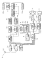
- FIG. 1 is a block diagram illustrating a schematic configuration of a television receiver X according to an embodiment of the present invention.
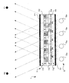
- the schematic diagram which shows schematic structure of the liquid crystal display part provided in the television receiver X which concerns on embodiment of this invention.
- the figure for demonstrating the dual view mode in the television receiver X which concerns on embodiment of this invention.
- the flowchart for demonstrating an example of the procedure of the operation mode control process performed with the television receiver X which concerns on embodiment of this invention.
- FIG. 3 is a block diagram illustrating a schematic configuration of a television receiver X according to a second embodiment.
- FIG. 3 is a block diagram illustrating a schematic configuration of a television receiver X according to a second embodiment.
- FIG. 6 is a diagram for explaining an example of a remote control according to Embodiment 2.
- FIG. 10 is a diagram for explaining an example of a display image viewed from a user in the dual view mode according to the second embodiment. The flowchart for demonstrating the other example of an operation mode control process.
- the television receiver X includes a plurality of tuners 1a and 1b, an external input unit 2, a video switching circuit 3, two video processing circuits 4a and 4b, and a stereoscopic video processing circuit 4c.
- a screen synthesis switching circuit 5 an LCD control circuit 6, a liquid crystal display unit 7, a control circuit 8, a remote control interface (I / F) circuit 9, a remote control 9a, a voice switching circuit 10, and two voice processes.
- the circuit 11a, 11b, two amplifiers 12a, 12b, a speaker 13, and an audio external output unit 14 are provided.
- the television receiver X includes components included in a general television receiver in addition to the components described here. Further, when viewing a stereoscopic video (3D video) using the television receiver X, the user uses 3D glasses (stereoscopic display glasses) 30 described later.
- the television receiver X and the 3D glasses 30 are an example of a stereoscopic video display system according to the present invention.
- the control circuit 8 is used as an MPU 8a which is an arithmetic means, a ROM 8b (EPROM) which is a storage means in which a control program executed by the MPU 8a is stored in advance, and a memory which stores setting information written by processing executed by the MPU 8a.
- EEPROM 8c and the like and comprehensively control the entire television receiver X.
- the remote control interface circuit 9 acquires the content of the user's operation input to the remote control 9a from the remote control 9a for operating the television receiver X by wireless transmission such as infrared transmission, and the control circuit 8 Is to be transmitted.
- the remote controller 9a is provided with general operation keys 9b for performing various operations such as channel selection, volume adjustment, and power ON / OFF of a television broadcast viewed on the television receiver X.
- Each of the tuners 1a and 1b broadcasts a signal (hereinafter referred to as a broadcast signal) in which video signals for a plurality of channels of various television broadcasts such as terrestrial digital broadcasting and BS / CS broadcasting and audio signals synchronized with the images are superimposed.
- a broadcast signal a signal in which video signals for a plurality of channels of various television broadcasts such as terrestrial digital broadcasting and BS / CS broadcasting and audio signals synchronized with the images are superimposed.
- the tuners 1a and 1b extract (select) a broadcast channel signal instructed from the control circuit 8 from the broadcast signal, extract a video signal and an audio signal by detecting the extracted signal, and extract the video signal and the audio signal.
- Each of the signals is transmitted to the video switching circuit 3 and the audio switching circuit 10 respectively.
- the external input unit 2 receives externally input video signals and audio signals such as composite video signals and audio signals, separate video signals and audio signals (so-called S terminal signals), and the like. It is an interface for transmitting them to the video switching circuit 3 and the audio switching circuit 10 respectively.
- the audio switching circuit 10 inputs audio signals from each of the tuners 1a and 1b and an audio signal from the external input unit 2, and two arbitrary audio signals (two sets of audio signals in the case of stereo). Signal) is transmitted to each of the two sound processing circuits 11a and 11b in accordance with an instruction from the control circuit 8.
- the control circuit 8 transmits an audio signal corresponding to the video signal transmitted from the video switching circuit 3 to the video processing circuit 4a, from the audio switching circuit 10 to the audio processing circuit 11a, and from the video switching circuit 3 to the video processing circuit.
- the video switching circuit 3 and the audio switching circuit 10 are controlled so that the audio signal corresponding to the video signal transmitted to 4b is transmitted from the audio switching circuit 10 to the audio processing circuit 11b.
- the audio processing circuits 11 a and 11 b perform various signal processing (for example, equalization processing, surround processing, etc.) on the audio signal transmitted from the audio switching circuit 10 in accordance with an instruction from the control circuit 8.
- the amplifiers 12a and 12b perform a process of amplifying or attenuating the audio signals after various signal processing by the audio processing circuits 11a and 11b according to instructions from the control circuit 8, and the processed audio signals are connected to the speaker 13 and the external audio unit.
- the data is transmitted to each of the output units 14.
- the audio external output unit 14 is a terminal (interface) to which an earphone or a headphone is connected.
- the speaker 13 that outputs audio corresponding to the video input to the video processing circuit 4a and the audio external output that outputs audio corresponding to the video input to the video processing circuit 4b.
- a single television receiver X allows a plurality of users to use two channels of programs (video and audio based on signals input through the external input unit). Can be watched at the same time.
- the video switching circuit 3 selects any two video signals from the video signals input from the tuners 1a and 1b and the video signal input from the external input unit 2 in accordance with an instruction from the control circuit 8, The two selected video signals are individually transmitted to the two video processing circuits 4a and 4b.
- Each of the video processing circuits 4 a and 4 b performs various signal processing on each video signal transmitted from the video switching circuit 3.
- a / D conversion of the video signal separation of the horizontal and vertical synchronization signals from the video signal after A / D conversion, generation of a clock signal phase-synchronized with the synchronization signal, generation from the video signal after A / D conversion Separation of luminance and color signals, predetermined image quality improvement processing, and the like are performed, and the processed video signal is output to the screen composition switching circuit 5.
- a video based on a video signal transmitted from one video processing circuit 4a is referred to as a selected first video
- a video based on a video signal transmitted from the other video processing circuit 4b is referred to as a selected second video.
- the selected first video and the selected second video may be the same video.
- the stereoscopic video processing circuit 4c is provided between the video processing circuit 4a and the screen composition switching circuit 5, and in accordance with an instruction from the control circuit 8, the selected first video output from the video processing circuit 4a.
- a stereoscopic video display signal for allowing the user to view stereoscopically is generated, and the stereoscopic video display signal is output to the screen composition switching circuit 5.
- the stereoscopic video display signal is a video signal for alternately displaying a left-eye video and a right-eye video whose display positions on a liquid crystal panel 71 described later are different by a predetermined amount.
- the stereoscopic video processing circuit 4c generates a left-eye image and a right-eye image in which the image for each frame of the selected first video is slightly shifted left and right, and the left-eye image and the right-eye image are 1
- a stereoscopic video display signal composed of the left-eye video and the right-eye video is generated.
- the image for the left eye and the image for the right eye may be alternately displayed for each frame or every plurality of frames.
- the shift amount of the display position of the left-eye video and the right-eye video on the liquid crystal panel 71 is set in advance according to the degree of projection of the stereoscopic video.
- the display operation mode when the stereoscopic video display signal for alternately displaying the left-eye video and the right-eye video is output from the stereoscopic video processing circuit 4c in this way is the stereoscopic video display mode
- the selected first video is The display operation mode when it is output as it is is called a flat image display mode.
- the screen composition switching circuit 5 includes a dual view video signal corresponding to a later-described dual view mode that individually displays different images in two directions, and a normal image signal corresponding to a later-described single display mode that displays only one image. Is selectively generated in accordance with an instruction from the control circuit 8, and the video signal is transmitted to the LCD control circuit 6.
- the normal video signal is a normal general video signal for displaying the selected first video signal inputted from the video processing circuit 4a on the liquid crystal display unit 7 using all pixels. It is a video signal.
- the dual view video signal half of all the pixels (for example, one of the two adjacent pixels) are allocated for displaying the selected first video, and the remaining pixels are the selected second video.
- the screen composition switching circuit 5 has a function of superimposing the insertion information transmitted from the control circuit 8 on the video signal to be output or an output video from the video processing circuits 4a and 4b. 8 also has a function of converting the information transmitted from 8 into a video signal and outputting it.
- the LCD control circuit 6 is provided in the liquid crystal display unit 7 by controlling the liquid crystal display unit 7 based on the video signal, the vertical synchronization signal, the horizontal synchronization signal, etc. input from the screen composition switching circuit 5. An image based on the image signal is displayed on the liquid crystal panel 71.
- the liquid crystal display unit 7 includes a liquid crystal panel 71, a backlight 72, and the like, and displays an image on the liquid crystal panel 71 based on the video signal output from the screen composition switching circuit 5. is there.
- the backlight 72 illuminates the liquid crystal panel 71 from behind by a large number of LEDs 72 a arranged in a matrix on the back side of the liquid crystal panel 71.
- a cold cathode tube (fluorescent tube) may be used instead of the LED 72a.
- the liquid crystal panel 71 is disposed between the two polarizing plates 711, the two glass substrates 712 on which a transparent electrode layer (not shown) and an alignment film (not shown) are formed, and the glass substrate 712.
- a liquid crystal layer 713, a color filter layer 714, a transparent acrylic resin layer 715, and a parallax barrier layer 716 are included.
- a light transmitting portion 716 a that transmits light from the backlight 72 and a light shielding portion 716 b that blocks light from the backlight 72 correspond to each pixel in the horizontal direction of the display screen of the liquid crystal panel 71. It is formed alternately at the position.
- the translucent part 716a is formed with transparent glass or opening.
- the light projecting unit 716a and the light shielding unit 716b of the parallax barrier layer 716 and the pixels A and B alternately arranged in the liquid crystal layer 713 are arranged in the horizontal direction of the display screen of the liquid crystal panel 71. It is provided at a position shifted by a predetermined amount.
- the amount of deviation at this time may be appropriately determined depending on the angle at which the video composed of the pixels A and the video composed of the pixels B are to be displayed.
- the liquid crystal display unit 7 configured in this way, as shown in FIGS. 2 and 3, when the liquid crystal panel 71 is viewed from the liquid crystal panel 71 at a position P1 diagonally right forward, the pixel B of the liquid crystal layer 713 is used. Only the composed left screen M1 is visible, and the right screen M2 composed of the pixels A is not visible.
- the liquid crystal display unit 7 displays one image using the left screen M1 and another image using the right screen M2, thereby individually displaying two images in different directions from the liquid crystal panel 71. Can be displayed.
- the liquid crystal display unit 7 is an example of a multi-view video display means. If the same video signal is output to each of the pixels A and B, the same image can be displayed on the left screen M1 and the right screen M2 regardless of the viewing angle.
- the screen operation mode for displaying two images individually on the left screen M1 and the right screen M2 is a dual view mode, and the screen operation mode for displaying one image on both the left screen M1 and the right screen M2 is described below. This is called single display mode.
- an operation mode control process (see FIG. 4) described later is executed by the control circuit 8 to display an image on the liquid crystal panel 71 of the liquid crystal display unit 7.
- the dual view mode and the single display mode are switched to the remote controller 9a in addition to general operation keys 9b such as a channel selection key, a volume adjustment key, a menu key, and a power key.
- a display switching key 9e for switching the display mode is provided. Then, the control circuit 8 switches the operation mode when displaying an image on the liquid crystal panel 71 of the liquid crystal display unit 7 in accordance with the operation of the screen switch key 9c, the operation switch 9d, and the display switch key 9e of the remote controller 9a.
- a configuration in which various operation modes can be switched by an operation on a menu screen displayed by an operation of the remote controller 9a may be used.
- the operation mode control processing executed by the control circuit 8 in the television receiver X will be described with reference to the flowchart of FIG. 4, S1, S2,... Indicate processing procedure (step) numbers.
- the screen operation mode is set to the single display mode
- the display operation mode is set to the planar video display mode.
- the selected first video is displayed as it is as a planar video (2D video) on the entire surface of the liquid crystal panel 71 of the liquid crystal display unit 7.
- Step S1 First, in step S1, the control circuit 8 determines whether or not the screen switching key 9c of the remote controller 9a is operated. If it is determined that the screen switching key 9c has been operated (YES side of S1), the process proceeds to step S11. On the other hand, if it is determined that the screen switching key 9c has not been operated (NO side of S1), the process proceeds to step S2.
- Step S11 When the screen switching key 9c is operated (YES side of S1), in the subsequent step S11, the control circuit 8 determines whether or not the current screen operation mode is the single display mode. Specifically, the control circuit 8 determines based on the value of the screen state flag set in the EEPROM 8c as information indicating whether the dual view mode or the single display mode is selected. If it is determined that the current screen operation mode is the single display mode (YES side of S11), the process proceeds to step S12, and it is determined that the current screen operation mode is the dual view mode. Then (NO side of S11), the process proceeds to step S111.
- Step S12 the control circuit 8 notifies the video processing circuits 4a and 4b and the screen composition switching circuit 5 of a control command for switching the screen operation mode from the single display mode to the dual view mode, and performs processing.
- each of the video processing circuits 4 a and 4 b outputs a signal corresponding to each of the selected first video and the selected second video input from the video switching circuit 3 to the screen composition switching circuit 5.
- the screen composition switching circuit 5 generates the dual view video signal based on the selected first video and the selected second video input from the video processing circuits 4 a and 4 b and transmits the dual view video signal to the LCD control circuit 6. .
- the LCD control circuit 6 outputs the video signal of the selected first video to the pixel A of the liquid crystal panel 71 of the liquid crystal display unit 7 and outputs the video signal of the selected second video to the pixel B of the liquid crystal panel 71.
- the selected first image is displayed in the diagonally right direction from the liquid crystal panel 71
- the selected second image is displayed in the diagonally left direction from the liquid crystal panel 71.
- the control circuit 8 switches the screen to be operated to the left screen or the right screen depending on whether the operation switch 9d is set to the left screen M1 or the right screen M2, and the operation signal information from the remote control 9a.
- Various processes such as channel switching operation and volume adjustment operation are executed based on the above.
- step S111 the control circuit 8 notifies the video processing circuits 4a and 4b and the screen composition switching circuit 5 of a control command for switching the screen operation mode from the dual view mode to the single display mode. Is returned to step S1. Accordingly, only the video processing circuit 4 a outputs the video signal corresponding to the selected first video input from the video switching circuit 3 toward the screen composition switching circuit 5.
- the screen composition switching circuit 5 generates the normal video signal based on the video signal of the selected first video input from the video processing circuit 4 a and transmits it to the LCD control circuit 6. Accordingly, the LCD control circuit 6 outputs the selected first video to the entire liquid crystal panel 71 by outputting the video signal of the selected first video to both the pixel A and the pixel B of the liquid crystal panel 71 of the liquid crystal display unit 7. Display.
- Step S2 When the screen switching key 9c is not operated (NO side of S1), in the subsequent step S2, the control circuit 8 determines whether or not the display switching key 9e of the remote controller 9a is operated. If it is determined that the display switching key 9e has been operated (YES side of S2), the process proceeds to step S3. On the other hand, if it is determined that the display switching key 9e has not been operated (NO side of S2), the process returns to step S1.
- Step S3 the control circuit 8 determines whether or not the current display operation mode is the planar video display mode. Specifically, the control circuit 8 makes a determination based on the value of the display state flag set in the EEPROM 8c as information indicating whether the stereoscopic video display mode or the planar video display mode. If it is determined that the current display operation mode is the stereoscopic video display mode (NO side of S3), the process proceeds to step S4, and it is determined that the current display operation mode is the flat display mode. If done (YES side of S3), the process proceeds to step S5.
- Step S4 the control circuit 8 notifies the stereoscopic video processing circuit 4c and the LCD control circuit 6 of a control command for switching the display operation mode from the stereoscopic video display mode to the planar video display mode, and performs processing.
- the stereoscopic video processing circuit 4c outputs the video signal corresponding to the selected first video input from the video processing circuit 4a to the screen composition switching circuit 5 as it is without generating the stereoscopic video display signal. Therefore, if the screen operation mode of the liquid crystal display unit 7 is the single display mode, the plane image of the selected first image is displayed on the entire liquid crystal panel 71. If the screen operation mode is the dual view mode, the left screen of the liquid crystal panel 71 is displayed. The selected first video and the selected second video are displayed as a planar video on M1 and the right screen M2, respectively.
- Step S5 On the other hand, in step S5, the control circuit 8 notifies the stereoscopic video processing circuit 4c and the LCD control circuit 6 of a control command for switching the display operation mode from the planar video display mode to the stereoscopic video display mode, The process returns to step S1.
- the stereoscopic video processing circuit 4c allows the user to stereoscopically view the selected first video based on the video signal corresponding to the selected first video input from the video switching circuit 3.
- a video display signal is generated and output to the screen composition switching circuit 5.
- the LCD control circuit 6 alternately switches the left-eye video and the right-eye video on the liquid crystal display panel 71 based on the stereoscopic video display signal input from the screen composition switching circuit 5 and displays the left-eye video.
- the right eye image switching timing is transmitted to the 3D glasses 30 as a synchronization signal.
- the switching timing (synchronization signal) is not limited to that transmitted by the LCD control circuit 6.
- the switching timing of the left-eye video and the right-eye video is input from the stereoscopic video processing circuit 4c, and a synchronization signal is transmitted to the 3D glasses 30 according to the switching timing.
- a configuration in which the 3D synchronization signal transmission circuit 31 is separately provided is also conceivable.
- transmission / reception of the synchronization signal between the LCD control circuit 6 or the 3D synchronization signal transmission circuit 31 and the 3D glasses 30 may be performed by a conventionally known communication method using infrared rays or the like. Description of the communication method is omitted.
- a configuration in which the LCD control circuit 6 or the 3D synchronization signal transmission circuit 31 and the 3D glasses 30 are connected to each other by a power supply line or a signal line is conceivable. In this case, the synchronization signal may be transmitted through the signal line. .
- control circuit 8 the stereoscopic video processing circuit 4c, and the LCD control circuit 6 for displaying the stereoscopic video in the diagonally right direction from the liquid crystal panel 71 by the liquid crystal display unit 7 are examples of the stereoscopic video display means.
- the 3D glasses 30 are linked (synchronized) with the switching timing (synchronization signal) of the left-eye image and the right-eye image, and alternately enable the left-eye shutter and the right-eye shutter.
- the right eye image is observed alternately with the left eye and the right eye. Therefore, the user who uses the 3D glasses 30 can see the selected first image displayed on the liquid crystal panel 71 in three dimensions.
- the 3D glasses 30 may be conventionally known 3D glasses, such as those having a liquid crystal layer for switching light transmission and shielding (or scattering) in the field of view corresponding to the left eye and the right eye, for example.
- the 3D glasses 30 control the voltage applied to the liquid crystal layer in accordance with the switching timing, and alternately switch between valid and invalid of the left-eye and right-eye views.
- the user wearing 3D glasses observes the left-eye image with the left eye when the left-eye image is displayed, and observes the right-eye image with the right eye when the right-eye image is displayed. It can be viewed as a stereoscopic image.
- the stereoscopic video of the selected first video is displayed on the entire liquid crystal panel 71, but if the dual view mode, The selected first image is displayed as a stereoscopic image in the diagonally right direction from the liquid crystal panel 71, and the selected second image is displayed as a planar image in the diagonally left direction from the liquid crystal panel 71.
- the control circuit 8, the stereoscopic video processing circuit 4c, and the LCD control circuit 6 when the liquid crystal display unit 7 displays a flat image in the diagonally left direction from the liquid crystal panel 71 are examples of the flat image display means.
- the LCD control circuit 6 displays the stereoscopic video display signal corresponding to the selected first video.
- the left-eye image and the right-eye image are alternately displayed on the left screen M1 of the liquid crystal panel 71.
- the right image M2 of the liquid crystal panel 71 is a plane image based on the image signal corresponding to the selected second image. Is displayed.
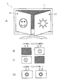
- the left eye image and the right eye image are displayed as shown in FIGS. 5B and 5C.
- the left eye shutter and the right eye shutter of the 3D glasses 30 operate in conjunction with the display, the state in which the left eye image is visible with the left eye and the state in which the right eye image is visible with the right eye are alternately repeated. Accordingly, the user wearing the 3D glasses 30 can see the selected first video in three dimensions by the liquid crystal panel 71.
- the selected second image can be viewed as a beautiful flat image.
- the user using the 3D glasses 30 alternately turns from the liquid crystal panel 71 toward the right diagonal direction based on the stereoscopic video display signal output from the stereoscopic video processing circuit 4c.
- the display image can be viewed three-dimensionally, and a user who does not use the 3D glasses 30 is based on the planar image display signal output from the image processing circuit 4b.
- a normal planar image displayed from the liquid crystal panel 71 in an obliquely leftward direction can be viewed. Therefore, a user who does not have the 3D glasses 30 is not forced to view the hard-to-view video in which the right-eye video and the left-eye video are overlapped, and the television receiver X can be watched simultaneously by a large number of people. .
- the display differs in three directions, left diagonal, front, and right diagonal. It may be configured to perform multi-view display for displaying video. In this case, only one of the three directions is used for stereoscopic video display and the other two are used for planar video display, or only one is used for planar video display and the other two are used for stereoscopic video display. It is possible to use.
- a configuration in which the parallax barrier layer 716 provided in the liquid crystal panel 71 of the liquid crystal display unit 7 includes the fixed light-transmitting portion 716a and the light-shielding portion 716b has been described.
- Another embodiment may be a liquid crystal layer in which light transmission and light shielding can be switched at positions corresponding to the part 716a and the light shielding part 716b.
- the parallax barrier in the dual view mode, the parallax barrier is enabled and light is blocked at a position corresponding to the light shielding unit 716b.
- the parallax barrier In the single display mode, the parallax barrier is disabled and light is transmitted at a position corresponding to the light shielding unit 716b. You can do it.
- the configuration in which the stereoscopic video processing circuit 4c is provided only between the video processing circuit 4a and the screen composition switching circuit 5 has been described as an example.
- a configuration in which a stereoscopic video processing circuit 4d (not shown) similar to the stereoscopic video processing circuit 4c is provided between the video processing circuit 4b and the screen composition switching circuit 5 can be considered as another embodiment.
- the control circuit 8 may execute the following steps S21 to S22 in addition to the operation mode control process (see the flowchart of FIG. 4) described in the embodiment. Conceivable.
- step S21 when it is determined that the display switching key 9e has been operated in step S2 (YES side of S2), in the subsequent step S21, the control circuit 8 determines that the current screen operation mode is It is determined whether or not the dual view mode is set. If it is determined that the current screen operation mode is the single display mode (NO side of S21), the process proceeds to step S3, and it is determined that the current screen operation mode is the dual view mode. When done (YES side of S21), the process proceeds to step S22. In step S22, the control circuit 8 operates the display switching key 9e for the left screen or the right screen depending on whether the operation switch 9d of the remote control 9a is set to the left screen or the right screen. It is specified whether it is.
- each display operation mode of the left screen M1 of the liquid crystal panel 71 of the liquid crystal display part 7 and the right screen M2 can be freely switched between the said three-dimensional video display mode and the said planar video display mode. be able to.
- Embodiment 2 The second embodiment relates to a mode in which both the selected first video and the selected second video are stereoscopic videos.
- the selected first video and the selected second video are the same stereoscopic video or different stereoscopic videos, and the selected first video and the selected second video are stereoscopic videos having different degrees of protrusion.
- the degree of projection of a stereoscopic image is referred to as depth. When the depth is large (deep), the degree of projection of the stereoscopic image is large, and when the depth is small (shallow), the degree of projection of the stereoscopic image is small.
- FIG. 7 is a block diagram illustrating a schematic configuration of the television receiver X according to the second embodiment.
- the stereoscopic video processing circuit 4 c generates a stereoscopic video display signal for allowing the user to view the selected first video stereoscopically in accordance with an instruction from the control circuit 8, and outputs the stereoscopic video display signal to the screen composition switching circuit 5.
- the stereoscopic video display signal is a video signal in which the display positions of the left-eye video and the right-eye video on the liquid crystal panel 71 differ by an amount corresponding to an instruction from the control circuit 8.
- the television receiver X according to Embodiment 2 further includes a stereoscopic video processing circuit 4d.
- the stereoscopic video processing circuit 4d is provided between the video processing circuit 4b and the screen composition switching circuit 5.
- the stereoscopic video processing circuit 4 d generates a stereoscopic video display signal for allowing the user to stereoscopically view the selected second video according to an instruction from the control circuit 8 and outputs the stereoscopic video display signal to the screen composition switching circuit 5. To do.
- the stereoscopic video processing circuit 4c generates a left-eye image and a right-eye image in which the image for each frame of the selected first video is shifted left and right by an amount instructed by the control circuit 8, respectively.
- the stereoscopic video processing circuit 4c generates a stereoscopic video display signal composed of a left-eye video and a right-eye video by alternately synthesizing the left-eye image and the right-eye image every half of one frame.
- the stereoscopic video processing circuit 4d generates a left-eye image and a right-eye image obtained by shifting the image for each frame of the selected second video left and right by the amounts instructed by the control circuit 8, respectively.
- the stereoscopic video processing circuit 4c generates a stereoscopic video display signal of a selected second video composed of a left eye video and a right eye video.
- the shift amount (predetermined amount) between the display positions of the left-eye image and the right-eye image that the control circuit 8 instructs the stereoscopic video processing circuits 4c, 4d is stored in the ROM 8b or the EEPROM 8c in advance.
- the control circuit 8 notifies the stereoscopic video processing circuits 4c and 4d and the LCD control circuit 6 of a control command for switching the display operation mode from the planar video display mode to the stereoscopic video display mode based on a signal from the remote controller 9a.
- the image composition switching circuit 5 receives the stereoscopic video signal of the selected first video or the selected second video from the stereoscopic video processing circuits 4c and 4d, respectively, and outputs the stereoscopic video signal to the LCD control circuit 6.
- the LCD control circuit 6 displays each left-eye image and right-eye image on the liquid crystal display panel 71 based on the stereoscopic video signal of the selected first video or the selected second video input from the image composition switching circuit 5.
- the stereoscopic video display system includes 3D glasses 30a and 30b.
- the 3D glasses 30a are glasses for viewing a stereoscopic image of the selected first image displayed on the left screen M1, for example.
- the 3D glasses 30b are glasses for viewing a stereoscopic image of the selected second image displayed on the right screen M2, for example.
- the LCD control circuit 6 transmits the switching timing of each left-eye video and right-eye video to the 3D glasses 30a and 30b as synchronization signals based on the stereoscopic video signal of the selected first video or the selected second video.
- the 3D glasses 30a and 30b alternately enable the left eye shutter and the right eye shutter in synchronization (synchronization) with the switching timing (synchronization signal) of the left eye video and the right eye video related to the selected first video and the selected second video, respectively.
- FIG. 8 is a diagram for explaining an example of the remote controller 9a according to the second embodiment.
- the remote controller 9a includes a 3D depth key 9f in addition to the various keys 9b, 9c, 9e and the operation changeover switch 9d.
- the 3D depth key 9f is a button for switching the degree of projection of the stereoscopic video displayed on the left screen M1 or the right screen M2.
- the display switching key 9e each time the 3D depth key 9f is pressed, the stereoscopic video displayed on the left screen M1 or the right screen M2 is displayed.
- the degree of popping is switched. That is, the depth mode is switched between the large depth mode and the small depth mode.
- the stereoscopic video is displayed on both the left screen M1 and the right screen M2 by operating the operation switching switch 9d and the display switching key 9e. Further, by operating the operation key 9b, a stereoscopic video of the same channel can be displayed on both the left screen M1 and the right screen M2, or a stereoscopic video of a different channel can be displayed. Furthermore, when stereoscopic images of the same or different programs are displayed on both the left screen M1 and the right screen M2, a stereoscopic video having different depths on the left screen M1 and the right screen M2 by operating the 3D depth key 9f. Can be displayed.
- FIG. 9 is a diagram for explaining an example of a display image viewed from the user in the dual view mode according to the second embodiment.
- the stereoscopic video display mode is selected on both the left screen M1 and the right screen M2
- the stereoscopic video is displayed in both two different directions of the liquid crystal panel 71.
- the television receiver X can display the same stereoscopic video on the left screen M1 and the right screen M2 by selecting a channel from the remote controller 9a, for example, or can display different stereoscopic video.
- FIG. 9A shows an example in which the same stereoscopic video is displayed on the left screen M1 and the right screen M2. As shown in FIGS.
- the left-eye shutter and the right-eye shutter of the 3D glasses 30a and 30b are operated in conjunction with the display of the left-eye video and the right-eye video, and are visible with the left and right eyes. Alternately change. This is the same on both the left screen M1 and the right screen M2.
- FIG. 9A shows an example in which stereoscopic images having different depths are displayed on the left screen M1 and the right screen M2 by the operation of the 3D depth key 9f.
- the shift amount of the display position of the left eye video and the right eye video on the right screen M2 is larger than the shift amount of the display position of the left eye video and the right eye video on the left screen M1.
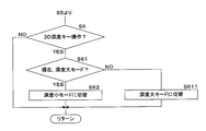
- FIG. 10 is a flowchart for explaining another example of the operation mode control process.
- the operation mode control process executed by the control circuit 8 will be described.
- the screen operation mode is set to the large depth mode.
- FIG. 10 shows processing added between step S5 and return in FIG.
- Step S6 The control circuit 8 determines whether or not the 3D depth key 9f is operated. Here, when the control circuit 8 determines that the 3D depth key 9f is not operated (NO side of S6), the process returns to step S1. When the control circuit 8 determines that the 3D depth key 9f has been operated (YES side of S6), the process proceeds to step S61.
- Step S61 The control circuit 8 determines whether or not the current screen operation mode is the large depth mode. If the control circuit 8 determines that the current screen operation mode is the large depth mode (YES side of step S61), the process proceeds to step S62. If the control circuit 8 determines that the current screen operation mode is not the large depth mode (NO side of step S61), the process proceeds to step S611.
- Step S62 The control circuit 8 notifies the stereoscopic video processing circuits 4c and 4d and the screen composition switching circuit 5 of a control command for switching the screen operation mode from the large depth mode to the small depth mode, and returns the processing to step S1.
- Step S611 The control circuit 8 notifies the stereoscopic video processing circuits 4c and 4d and the screen composition switching circuit 5 of a control command for switching the screen operation mode from the small depth mode to the large depth mode, and returns the processing to step S1.
- the same stereoscopic video or different stereoscopic videos can be displayed in two directions, left and right.
- the television receiver X can display three-dimensional images with different degrees of protrusion in two directions, the left diagonal and the right diagonal.
- a stereoscopic image is displayed as if it is a three-dimensional image due to the difference between the images seen by the left and right eyes, and therefore the burden on the user's eyes is large. For example, in the case of a child or an elderly person, it is preferable that the amount of projection of a stereoscopic image is small.
- users of a wide range of ages can simultaneously view the same television by changing the amount of 3D image pop-up between different directions on the left and right of the screen.
- a stereoscopic image can be enjoyed using the receiver X.
- the 3D images displayed for both people It will be a satisfactory image.
- the single view mode can be selected, and when viewing the television receiver X with multiple persons, the dual view mode can be selected. That is, since the screen operation mode can be switched according to the situation, the television receiver X has high operability.
- the 3D depth key 9f of the remote controller 9a can select a large depth mode and a small depth mode.
- the television receiver X may display stereoscopic images in different depth modes determined in advance in association with the left screen M1 and the right screen M2.
- the television receiver X displays a large depth mode stereoscopic image on the left screen M1 and a small depth mode stereoscopic image on the right screen M2.
- the shift amounts of the display positions of the left eye video and the right eye video corresponding to the large depth mode and the small depth mode that the control circuit 8 instructs the stereoscopic video processing circuits 4c and 4d are stored in the ROM 8b or the EEPROM 8c in advance.
- the television receiver X may continuously change the depth of the stereoscopic video to be displayed.
- a slider is provided in the remote control 9a instead of the 3D depth key 9f so that the depth can be set finely according to the position of the slider knob.
- the control circuit 8 instructs the stereoscopic video processing circuits 4c and 4d to generate a left-eye image and a right-eye image that are shifted by an amount instructed.
- you may display on the screen of the television receiver X the indicator which shows the depth of a three-dimensional image more finely.
- a button for increasing the depth and a button for decreasing the depth such as a volume control button, are provided on the remote control 9a.
- Embodiment 2 is as described above, and the others are the same as in Embodiment 1. Therefore, the same reference numerals are assigned to corresponding parts, and detailed description thereof is omitted.
- the present invention can be applied to a liquid crystal display device such as a liquid crystal television receiver or a liquid crystal display device.
- X Television receiver (an example of a stereoscopic video display device) 1a, 1b: tuner 2: external input unit 3: video switching circuit 4a: video processing circuit 4b: video processing circuit 4c: stereoscopic video processing circuit 4d: stereoscopic video processing circuit 5: screen composition switching circuit 6: LCD control circuit 7: Liquid crystal display 71: Liquid crystal panel 72: Backlight 8: Control circuit 8a: MPU 8b: ROM 8c: EEPROM 9: Remote control signal receiving circuit 9a: Remote control 9b: Operation key 9c: Screen change key 9d: Operation change switch 9e: Display change key 9f: Depth change key 10: Audio change circuit 11a, 11b: Audio processing circuit 12a, 12b: Amplifier 13: Speaker 14: Audio external output unit 20: Broadcast receiving antenna 30, 30a, 30b: 3D glasses (stereoscopic display glasses) S1, S2,... S6: Processing procedure (step) number
Landscapes
- Physics & Mathematics (AREA)
- Engineering & Computer Science (AREA)
- Multimedia (AREA)
- Signal Processing (AREA)
- General Physics & Mathematics (AREA)
- Optics & Photonics (AREA)
- Testing, Inspecting, Measuring Of Stereoscopic Televisions And Televisions (AREA)
- Control Of Indicators Other Than Cathode Ray Tubes (AREA)
- Liquid Crystal Display Device Control (AREA)
Abstract
3Dメガネを用いて立体映像を視聴することのできる立体映像表示装置であって、3Dメガネを有さないユーザに対しては見えやすい平面映像を視聴させることが可能な立体映像表示装置及び立体映像表示システムを提供すること。 液晶パネル71から右方向及び左方向に異なる映像を個別に表示するマルチビュー映像表示機能を有しており、該マルチビュー映像表示機能により液晶パネル71から右方向に向けた左画面M1に、表示位置が所定量異なる左目映像及び右目映像を交互に表示させると共に、該マルチビュー映像表示機能により液晶パネル71から左方向に向けた右画面M2に平面映像を表示させる。
Description
本発明は、表示位置が所定量異なる左目映像及び右目映像を交互に液晶パネルに表示することにより、左目映像及び右目映像の表示に連動して左目及び右目の視界が交互に有効となる3Dメガネを用いるユーザに立体映像を見せる立体映像表示装置に関するものである。
従来から、表示位置が若干ずれた左目映像及び右目映像を交互に液晶パネルに表示することにより、左目映像及び右目映像の表示に連動して左目及び右目の視界が交互に有効となる3Dメガネを用いるユーザに立体映像を見せることのできる立体映像表示装置が知られている(例えば、特許文献1参照)。
具体的に、ユーザは3Dメガネを掛けることで、左目映像が表示されているときは左目だけでその左目映像を観察し、右目映像が表示されているときは右目だけでその右目映像を観察することとなり、その表示映像を立体的に見ることができる。なお、3Dメガネにより左目及び右目の視界を交互に有効化及び無効化する手法としては、特許文献1にも開示されているように、例えば液晶シャッタにより光の透過及び遮蔽を切り替えることや光の透過及び散乱を切り替えること等が考えられる。また、液晶パネルにおける左目映像及び右目映像の表示位置のズレ量は、立体映像の飛び出しの程度などに応じて予め設定される。
具体的に、ユーザは3Dメガネを掛けることで、左目映像が表示されているときは左目だけでその左目映像を観察し、右目映像が表示されているときは右目だけでその右目映像を観察することとなり、その表示映像を立体的に見ることができる。なお、3Dメガネにより左目及び右目の視界を交互に有効化及び無効化する手法としては、特許文献1にも開示されているように、例えば液晶シャッタにより光の透過及び遮蔽を切り替えることや光の透過及び散乱を切り替えること等が考えられる。また、液晶パネルにおける左目映像及び右目映像の表示位置のズレ量は、立体映像の飛び出しの程度などに応じて予め設定される。
しかしながら、3Dメガネを用いて立体映像を視聴することのできる立体映像表示装置では、左目映像及び右目映像各々が少しずれた位置で重なって表示されるため、3Dメガネを用いないユーザにとってその表示映像は非常に見えづらいものである。
そのため、このような立体映像表示装置を多人数のユーザが同時に視聴する場合には、そのユーザの数に応じた3Dメガネを用意する必要があり、その3Dメガネの数が不足する場合には、3Dメガネを有さないユーザが見えづらい映像の視聴を強いられることとなるため、現実的には多人数による視聴が困難であった。
従って、本発明は上記事情に鑑みてなされたものであり、その目的とするところは、3Dメガネを用いて立体映像を視聴することのできる立体映像表示装置であって、3Dメガネを有さないユーザに対しては見えやすい平面映像を視聴させることが可能な立体映像表示装置及び立体映像表示システムを提供することにある。
そのため、このような立体映像表示装置を多人数のユーザが同時に視聴する場合には、そのユーザの数に応じた3Dメガネを用意する必要があり、その3Dメガネの数が不足する場合には、3Dメガネを有さないユーザが見えづらい映像の視聴を強いられることとなるため、現実的には多人数による視聴が困難であった。
従って、本発明は上記事情に鑑みてなされたものであり、その目的とするところは、3Dメガネを用いて立体映像を視聴することのできる立体映像表示装置であって、3Dメガネを有さないユーザに対しては見えやすい平面映像を視聴させることが可能な立体映像表示装置及び立体映像表示システムを提供することにある。
上記目的を達成するために本発明は、液晶パネルから複数の方向に異なる映像を個別に表示するマルチビュー映像表示手段と、前記マルチビュー映像表示手段により少なくとも一つの方向に、表示位置が所定量異なる左目映像及び右目映像を交互に表示させる立体映像表示手段と、前記マルチビュー映像表示手段により少なくとも一つの方向に平面映像を表示させる平面映像表示手段とを備えてなることを特徴とする立体映像表示装置として構成される。
ここで、前記マルチビュー映像表示手段は、前記液晶パネルから二方向に異なる映像を表示する所謂デュアルビュー表示を行うものであることが考えられる。この場合、その二方向のうち一方に前記平面映像が表示され、他方に前記左目映像及び前記右目映像が交互に表示されることとなる。
本発明は、液晶パネルに対する複数の方向夫々に同一又は異なる映像を該液晶パネルに表示するマルチビュー映像表示手段と、前記マルチビュー映像表示手段が表示する少なくとも一つの方向の映像に対応する左目映像及び右目映像を前記液晶パネルの異なる位置に交互に表示する立体映像表示手段とを備えてなることを特徴とする。
本発明では、マルチビュー映像表示手段及び立体映像表示手段を備えている。マルチビュー映像表示手段は、液晶パネルに対して複数の方向に夫々同一又は異なる映像を液晶パネルに表示する手段であり、液晶パネルから複数の方向に射出される同一又は異なる映像を個別に液晶パネルに表示する手段でもある。立体映像表示手段は、液晶パネルに対する複数の方向のうち、少なくとも一つの方向に表示される映像について、左目映像と右目映像とを生成し、これらの映像を液晶パネルの異なる位置に表示する。
本発明は、前記立体映像表示手段は、前記マルチビュー映像表示手段が表示する一の方向の映像に対応する左目映像及び右目映像を所定量離れた位置に交互に表示し、該マルチビュー映像表示手段が表示する他の方向の映像に対応する左目映像及び右目映像を他の所定量離れた位置に交互に表示するものである。
本発明では、一の方向に表示される左目映像及び右目映像の間の距離と他の方向に表示される左目映像及び右目映像の間の距離とは異なる。
また、本発明は、液晶パネルから複数の方向に異なる映像を個別に表示するマルチビュー映像表示手段と、前記マルチビュー映像表示手段により少なくとも一つの方向に、表示位置が所定量異なる左目映像及び右目映像を交互に表示させる立体映像表示手段と、前記マルチビュー映像表示手段により少なくとも一つの方向に平面映像を表示させる平面映像表示手段と、前記立体映像表示手段による前記左目映像及び前記右目映像の表示に連動して左目及び右目の視界を交互に有効化させる立体表示メガネとを備えてなることを特徴とする立体映像表示システムとして捉えてもよい。
本発明によれば、前記左目映像及び前記右目映像の表示に連動して左目及び右目の視界が交互に有効となる立体表示メガネ(3Dメガネ)を用いるユーザは、前記立体映像表示手段によって前記液晶パネルから少なくとも一方向に向けて表示される前記左目映像及び前記右目映像を見ることにより表示映像を立体的に見ることができる。また、前記立体表示メガネを用いないユーザは、前記平面映像表示手段によって前記液晶パネルから少なくとも一方向に向けて表示される前記平面映像を見ることができる。従って、多人数による同時視聴が可能となる。
本発明は、液晶パネルに対する複数の方向夫々に同一又は異なる映像を該液晶パネルに表示するマルチビュー映像表示手段と、前記マルチビュー映像表示手段が表示する少なくとも一つの方向の映像に対応する左目映像及び右目映像を前記液晶パネルの異なる位置に交互に表示する立体映像表示手段と、前記立体映像表示手段による左目映像及び右目映像の表示に連動して左目及び右目の視界を交互に有効化させる立体表示メガネとを備えてなることを特徴とする。
本発明では、マルチビュー映像表示手段、立体映像表示手段及び立体表示メガネを備えている。マルチビュー映像表示手段は、液晶パネルに対して複数の方向に夫々同一又は異なる映像を液晶パネルに表示する手段であり、液晶パネルから複数の方向に射出される同一又は異なる映像を個別に液晶パネルに表示する手段でもある。立体映像表示手段は、液晶パネルに対する複数の方向のうち、少なくとも一つの方向に表示される映像について、左目映像と右目映像とを生成し、これらの映像を液晶パネルの異なる位置に表示する。立体表示メガネは、液晶パネルに左目映像及び右目映像が交互に表示される場合、各表示に連動して左目及び右目の視界を交互に有効化する。
本発明は、前記立体映像表示手段は、前記マルチビュー映像表示手段が表示する一の方向の映像に対応する左目映像及び右目映像を所定量離れた位置に交互に表示し、該マルチビュー映像表示手段が表示する他の方向の映像に対応する左目映像及び右目映像を他の所定量離れた位置に交互に表示するものである。
本発明では、一の方向に表示される左目映像及び右目映像の間の距離と他の方向に表示される左目映像及び右目映像の間の距離とは異なる。
本発明によれば、前記立体表示メガネを用いるユーザは、前記立体映像表示手段によって前記液晶パネルから少なくとも一方向に向けて表示される前記左目映像及び前記右目映像を見ることにより表示映像を立体的に見ることができ、前記立体表示メガネを用いないユーザは、前記平面映像表示手段によって前記液晶パネルから少なくとも一方向に向けて表示される前記平面映像を見ることができるため、多人数による同時視聴が可能となる。
以下添付図面を参照しながら、本発明の実施の形態について説明し、本発明の理解に供する。尚、以下の実施の形態は、本発明を具体化した一例であって、本発明の技術的範囲を限定する性格のものではない。
実施の形態1
まず、図1に示すブロック図を用いて、本発明の実施の形態に係るテレビジョン受像機X(立体映像表示装置の一例)の概略構成について説明する。
図1に示すように、テレビジョン受像機Xは、複数のチューナ1a,1bと、外部入力部2と、映像切替回路3と、2つの映像処理回路4a,4bと、立体映像処理回路4cと、画面合成切替回路5と、LCD制御回路6と、液晶表示部7と、制御回路8と、リモコンインターフェース(I/F)回路9と、リモコン9aと、音声切替回路10と、2つの音声処理回路11a,11bと、2つのアンプ12a,12bと、スピーカ13と、音声外部出力部14とを具備して構成されている。なお、テレビジョン受像機Xは、ここで説明する構成要素以外にも、一般的なテレビジョン受像機が有する構成要素を備えている。
また、ユーザは、テレビジョン受像機Xを用いて立体映像(3D映像)を視聴する際には、後述の3Dメガネ(立体表示メガネ)30を使用する。ここに、テレビジョン受像機X及び3Dメガネ30が本発明に係る立体映像表示システムの一例である。
まず、図1に示すブロック図を用いて、本発明の実施の形態に係るテレビジョン受像機X(立体映像表示装置の一例)の概略構成について説明する。
図1に示すように、テレビジョン受像機Xは、複数のチューナ1a,1bと、外部入力部2と、映像切替回路3と、2つの映像処理回路4a,4bと、立体映像処理回路4cと、画面合成切替回路5と、LCD制御回路6と、液晶表示部7と、制御回路8と、リモコンインターフェース(I/F)回路9と、リモコン9aと、音声切替回路10と、2つの音声処理回路11a,11bと、2つのアンプ12a,12bと、スピーカ13と、音声外部出力部14とを具備して構成されている。なお、テレビジョン受像機Xは、ここで説明する構成要素以外にも、一般的なテレビジョン受像機が有する構成要素を備えている。
また、ユーザは、テレビジョン受像機Xを用いて立体映像(3D映像)を視聴する際には、後述の3Dメガネ(立体表示メガネ)30を使用する。ここに、テレビジョン受像機X及び3Dメガネ30が本発明に係る立体映像表示システムの一例である。
制御回路8は、演算手段であるMPU8a、そのMPU8aによって実行される制御プログラムが予め格納される記憶手段であるROM8b(EPROM)、MPU8aが実行する処理によって書き込まれる設定情報を記憶するメモリとして利用されるEEPROM8cなどを備え、当該テレビジョン受像機X全体を統括的に制御する。
リモコンインターフェース回路9は、当該テレビジョン受像機Xの操作用のリモコン9aから、赤外線伝送等の無線伝送によって、リモコン9aに対するユーザの操作入力の内容を取得し、その操作入力の内容を制御回路8に伝送するものである。例えば、リモコン9aには、テレビジョン受像機Xで視聴するテレビジョン放送のチャンネル選択や音量調節、電源ON/OFFなどの各種操作を行う一般的な操作キー9bが設けられている。
リモコンインターフェース回路9は、当該テレビジョン受像機Xの操作用のリモコン9aから、赤外線伝送等の無線伝送によって、リモコン9aに対するユーザの操作入力の内容を取得し、その操作入力の内容を制御回路8に伝送するものである。例えば、リモコン9aには、テレビジョン受像機Xで視聴するテレビジョン放送のチャンネル選択や音量調節、電源ON/OFFなどの各種操作を行う一般的な操作キー9bが設けられている。
チューナ1a,1b各々は、地上デジタル放送やBS・CS放送などの各種テレビジョン放送の複数チャンネル分の映像信号及びその映像と同期した音声信号が重畳された信号(以下、放送信号という)を放送受信アンテナ20により受信する。そしてチューナ1a,1bは、制御回路8から指示された放送チャンネルの信号を前記放送信号から抽出(選局)するとともに、その抽出信号の検波によって映像信号及び音声信号を取り出し、その映像信号及び音声信号の各々を映像切替回路3及び音声切替回路10各々へ伝送するものである。
また、外部入力部2は、外部からコンポジット方式の映像信号及び音声信号や、セパレート方式の映像信号及び音声信号(いわゆるS端子の信号)等の外部入力映像信号及び外部入力音声信号を入力し、それらを映像切替回路3及び音声切替回路10各々へ伝送するインターフェースである。
また、外部入力部2は、外部からコンポジット方式の映像信号及び音声信号や、セパレート方式の映像信号及び音声信号(いわゆるS端子の信号)等の外部入力映像信号及び外部入力音声信号を入力し、それらを映像切替回路3及び音声切替回路10各々へ伝送するインターフェースである。
音声切替回路10は、チューナ1a,1b各々からの音声信号及び外部入力部2からの音声信号を入力し、それらの音声信号のうちの任意の2つの音声信号(ステレオの場合は2組の音声信号)各々を、制御回路8からの指示に従って2つの音声処理回路11a,11b各々に伝送するものである。ここで、制御回路8は、映像切替回路3から映像処理回路4aへ伝送される映像信号に対応する音声信号が音声切替回路10から音声処理回路11aへ伝送され、映像切替回路3から映像処理回路4bへ伝送される映像信号に対応する音声信号が音声切替回路10から音声処理回路11bへ伝送されるよう、映像切替回路3及び音声切替回路10を制御する。
音声処理回路11a,11bは、制御回路8からの指示に従って、音声切替回路10から伝送される音声信号に対して各種信号処理(例えば、イコライズ処理やサラウンド処理等)を行うものである。
アンプ12a,12bは、音声処理回路11a,11b各々による各種信号処理後の音声信号を、制御回路8からの指示に従って増幅或いは減衰させる処理を行い、処理後の各音声信号をスピーカ13及び音声外部出力部14の各々へ伝送するものである。なお、音声外部出力部14は、イヤホンやヘッドホンが接続される端子(インターフェース)である。
このように、テレビジョン受像機Xでは、映像処理回路4aに入力される映像に対応する音声を出力するスピーカ13と、映像処理回路4bに入力される映像に対応する音声を出力する音声外部出力部14とを備えることにより、後述するデュアルビューモードにおいて、1台のテレビジョン受像機Xで複数の利用者が異なる2つのチャンネルの番組(外部入力部を通じて入力される信号に基づく映像及び音声を含む)を同時に視聴することができる。
音声処理回路11a,11bは、制御回路8からの指示に従って、音声切替回路10から伝送される音声信号に対して各種信号処理(例えば、イコライズ処理やサラウンド処理等)を行うものである。
アンプ12a,12bは、音声処理回路11a,11b各々による各種信号処理後の音声信号を、制御回路8からの指示に従って増幅或いは減衰させる処理を行い、処理後の各音声信号をスピーカ13及び音声外部出力部14の各々へ伝送するものである。なお、音声外部出力部14は、イヤホンやヘッドホンが接続される端子(インターフェース)である。
このように、テレビジョン受像機Xでは、映像処理回路4aに入力される映像に対応する音声を出力するスピーカ13と、映像処理回路4bに入力される映像に対応する音声を出力する音声外部出力部14とを備えることにより、後述するデュアルビューモードにおいて、1台のテレビジョン受像機Xで複数の利用者が異なる2つのチャンネルの番組(外部入力部を通じて入力される信号に基づく映像及び音声を含む)を同時に視聴することができる。
一方、映像切替回路3は、チューナ1a,1b各々から入力される映像信号及び外部入力部2から入力される映像信号のうち、任意の2つの映像信号を制御回路8からの指示に従って選択し、その選択した2つの映像信号を2つ映像処理回路4a,4bへ個別に伝送するものである。
映像処理回路4a,4b各々は、映像切替回路3から伝送された映像信号各々に対して各種信号処理を行うものである。例えば、映像信号のA/D変換や、A/D変換後の映像信号から水平及び垂直同期信号の分離、その同期信号に位相同期したクロック信号の生成、A/D変換後の映像信号からの輝度信号及び色信号の分離、所定の画質改善処理等を行い、処理後の映像信号を画面合成切替回路5に向けて出力する。
以下、一方の映像処理回路4aから伝送される映像信号に基づく映像を選択第1映像、他方の映像処理回路4bから伝送される映像信号に基づく映像を選択第2映像と称する。もちろん、前記選択第1映像及び前記選択第2映像は同じ映像であってもよい。
映像処理回路4a,4b各々は、映像切替回路3から伝送された映像信号各々に対して各種信号処理を行うものである。例えば、映像信号のA/D変換や、A/D変換後の映像信号から水平及び垂直同期信号の分離、その同期信号に位相同期したクロック信号の生成、A/D変換後の映像信号からの輝度信号及び色信号の分離、所定の画質改善処理等を行い、処理後の映像信号を画面合成切替回路5に向けて出力する。
以下、一方の映像処理回路4aから伝送される映像信号に基づく映像を選択第1映像、他方の映像処理回路4bから伝送される映像信号に基づく映像を選択第2映像と称する。もちろん、前記選択第1映像及び前記選択第2映像は同じ映像であってもよい。
また、立体映像処理回路4cは、映像処理回路4aと画面合成切替回路5との間に設けられており、制御回路8からの指示に従って、映像処理回路4aから出力された前記選択第1映像をユーザに立体的に視聴させるための立体映像表示信号を生成し、該立体映像表示信号を画面合成切替回路5に出力する。ここに、前記立体映像表示信号は、後述の液晶パネル71における表示位置が所定量異なる左目映像及び右目映像を交互に表示させるための映像信号である。
具体的に、立体映像処理回路4cは、前記選択第1映像の1フレームごとの画像を左右それぞれに少しずらした左目用画像及び右目用画像を生成し、その左目用画像及び右目用画像を1フレームの半分の時間ごとに交互に合成することにより、前記左目映像及び前記右目映像からなる立体映像表示信号を生成する。もちろん、左目用画像及び右目用画像を1フレーム又は複数フレームごとに交互に表示させるものであってもよい。なお、液晶パネル71における前記左目映像及び前記右目映像の表示位置のズレ量は、立体映像の飛び出しの程度などに応じて予め設定される。
以下、このように立体映像処理回路4cから前記左目映像及び前記右目映像を交互に表示するための立体映像表示信号が出力されるときの表示動作モードを立体映像表示モード、前記選択第1映像がそのまま出力されるときの表示動作モードを平面映像表示モードという。
具体的に、立体映像処理回路4cは、前記選択第1映像の1フレームごとの画像を左右それぞれに少しずらした左目用画像及び右目用画像を生成し、その左目用画像及び右目用画像を1フレームの半分の時間ごとに交互に合成することにより、前記左目映像及び前記右目映像からなる立体映像表示信号を生成する。もちろん、左目用画像及び右目用画像を1フレーム又は複数フレームごとに交互に表示させるものであってもよい。なお、液晶パネル71における前記左目映像及び前記右目映像の表示位置のズレ量は、立体映像の飛び出しの程度などに応じて予め設定される。
以下、このように立体映像処理回路4cから前記左目映像及び前記右目映像を交互に表示するための立体映像表示信号が出力されるときの表示動作モードを立体映像表示モード、前記選択第1映像がそのまま出力されるときの表示動作モードを平面映像表示モードという。
画面合成切替回路5は、二方向に異なる映像を個別に表示する後述のデュアルビューモードに対応したデュアルビュー映像信号と、一つの映像のみを表示する後述のシングル表示モードに対応したノーマル映像信号とのいずれかを、制御回路8からの指示に従って選択的に生成し、その映像信号をLCD制御回路6へ伝送するものである。
ここで、前記ノーマル映像信号は、通常の一般的な映像信号であり、映像処理回路4aから入力される前記選択第1映像の信号を全ての画素を用いて液晶表示部7に表示させるための映像信号である。
一方、前記デュアルビュー映像信号は、全画素のうちの半分の画素(例えば、隣接する2画素の一方)が前記選択第1映像の表示用に割り振られると共に、残りの画素が前記選択第2映像の表示用に割り振られて編成された映像信号である。
なお、画面合成切替回路5は、その他、制御回路8から伝送される挿入情報を、出力する映像信号にスーパーインポーズする機能や、映像処理回路4a,4bからの出力映像に代えて、制御回路8から伝送されてくる情報を映像信号に変換して出力する機能も備えている。
そして、LCD制御回路6は、画面合成切替回路5から入力された映像信号や垂直同期信号、水平同期信号などに基づいて液晶表示部7を制御することにより、該液晶表示部7に設けられた液晶パネル71に該映像信号に基づく映像を表示させる。
ここで、前記ノーマル映像信号は、通常の一般的な映像信号であり、映像処理回路4aから入力される前記選択第1映像の信号を全ての画素を用いて液晶表示部7に表示させるための映像信号である。
一方、前記デュアルビュー映像信号は、全画素のうちの半分の画素(例えば、隣接する2画素の一方)が前記選択第1映像の表示用に割り振られると共に、残りの画素が前記選択第2映像の表示用に割り振られて編成された映像信号である。
なお、画面合成切替回路5は、その他、制御回路8から伝送される挿入情報を、出力する映像信号にスーパーインポーズする機能や、映像処理回路4a,4bからの出力映像に代えて、制御回路8から伝送されてくる情報を映像信号に変換して出力する機能も備えている。
そして、LCD制御回路6は、画面合成切替回路5から入力された映像信号や垂直同期信号、水平同期信号などに基づいて液晶表示部7を制御することにより、該液晶表示部7に設けられた液晶パネル71に該映像信号に基づく映像を表示させる。
ここで、図2を用いて、液晶表示部7について説明する。
図2に示すように、液晶表示部7は、液晶パネル71及びバックライト72などを備えており、画面合成切替回路5から出力される映像信号に基づいて液晶パネル71に映像を表示するものである。
バックライト72は、液晶パネル71の背面側にマトリクス状に配置された多数のLED72aにより該液晶パネル71を背後から照明するものである。なお、LED72aに代えて冷陰極管(蛍光管)を用いてもよい。
一方、液晶パネル71は、二枚の偏光板711と、透明電極層(不図示)及び配向膜(不図示)が形成された二枚のガラス基板712と、ガラス基板712の間に配置された液晶層713、カラーフィルタ層714、透過性アクリル樹脂層715及び視差バリア層716とを有している。
図2に示すように、液晶表示部7は、液晶パネル71及びバックライト72などを備えており、画面合成切替回路5から出力される映像信号に基づいて液晶パネル71に映像を表示するものである。
バックライト72は、液晶パネル71の背面側にマトリクス状に配置された多数のLED72aにより該液晶パネル71を背後から照明するものである。なお、LED72aに代えて冷陰極管(蛍光管)を用いてもよい。
一方、液晶パネル71は、二枚の偏光板711と、透明電極層(不図示)及び配向膜(不図示)が形成された二枚のガラス基板712と、ガラス基板712の間に配置された液晶層713、カラーフィルタ層714、透過性アクリル樹脂層715及び視差バリア層716とを有している。
視差バリア層716には、バックライト72からの光を透過させる透光部716a及びバックライト72の光を遮蔽する遮光部716bが、液晶パネル71の表示画面の横方向の一画素ごとに対応する位置に交互に形成されている。なお、透光部716aは、透明ガラスや開口によって形成される。
ここで、液晶パネル71では、視差バリア層716の投光部716a及び遮光部716b各々と液晶層713に交互に配置された画素A,B各々とが、液晶パネル71の表示画面の横方向に所定量ずれた位置に設けられている。なお、このときのズレ量は、画素Aから構成される映像と画素Bから構成される映像とを表示したい角度によって適宜定めておけばよい。
このように構成された液晶表示部7では、図2及び図3に示すように、液晶パネル71から右斜め前方の位置P1で液晶パネル71を見た場合には、液晶層713の画素Bで構成される左画面M1だけが見えて、画素Aで構成される右画面M2は見えない。一方、液晶パネル71から左斜め前方の位置P2で液晶パネル71を見た場合には、液晶層713の画素Aで構成される右画面M2だけが見えて、画素Bで構成される左画面M1は見えない。したがって、液晶表示部7は、一つの映像を左画面M1を使用して表示し、他の映像を右画面M2を用いて表示することにより、液晶パネル71から異なる方向に二つの映像を個別に表示することができる。ここに、液晶表示部7がマルチビュー映像表示手段の一例である。
なお、画素A,B各々に同じ映像信号を出力すれば、左画面M1、右画面M2各々により、視野角にかかわらず同じ映像を見せることができる。
以下、二つの映像を左画面M1、右画面M2各々に個別に表示させるときの画面動作モードをデュアルビューモード、一つの映像を左画面M1、右画面M2に共に表示させるときの画面動作モードをシングル表示モードという。
ここで、液晶パネル71では、視差バリア層716の投光部716a及び遮光部716b各々と液晶層713に交互に配置された画素A,B各々とが、液晶パネル71の表示画面の横方向に所定量ずれた位置に設けられている。なお、このときのズレ量は、画素Aから構成される映像と画素Bから構成される映像とを表示したい角度によって適宜定めておけばよい。
このように構成された液晶表示部7では、図2及び図3に示すように、液晶パネル71から右斜め前方の位置P1で液晶パネル71を見た場合には、液晶層713の画素Bで構成される左画面M1だけが見えて、画素Aで構成される右画面M2は見えない。一方、液晶パネル71から左斜め前方の位置P2で液晶パネル71を見た場合には、液晶層713の画素Aで構成される右画面M2だけが見えて、画素Bで構成される左画面M1は見えない。したがって、液晶表示部7は、一つの映像を左画面M1を使用して表示し、他の映像を右画面M2を用いて表示することにより、液晶パネル71から異なる方向に二つの映像を個別に表示することができる。ここに、液晶表示部7がマルチビュー映像表示手段の一例である。
なお、画素A,B各々に同じ映像信号を出力すれば、左画面M1、右画面M2各々により、視野角にかかわらず同じ映像を見せることができる。
以下、二つの映像を左画面M1、右画面M2各々に個別に表示させるときの画面動作モードをデュアルビューモード、一つの映像を左画面M1、右画面M2に共に表示させるときの画面動作モードをシングル表示モードという。
このように構成された前記テレビジョン受像機Xでは、制御回路8によって後述の動作モード制御処理(図4参照)が実行されることにより、液晶表示部7の液晶パネル71への映像表示する際の動作モードが、前記デュアルビューモード、前記シングル表示モード、前記立体映像表示モード、前記平面映像表示モードなどに切り替えられる。
具体的に、テレビジョン受像機Xでは、リモコン9aに、チャンネル選択キーや音量調節キー、メニューキー、電源キーなどの一般的な操作キー9bの他、前記デュアルビューモード及び前記シングル表示モードを切り替える画面切替キー9cと、前記デュアルビューモードにおける操作対象を前記選択第1映像(左映像)又は前記選択第2映像(右映像)に切り替える操作切替スイッチ9dと、前記立体映像表示モード及び前記平面映像表示モードを切り替える表示切替キー9eとが設けられている。
そして、制御回路8は、リモコン9aの画面切替キー9c、操作切替スイッチ9d、表示切替キー9eの操作に応じて液晶表示部7の液晶パネル71に映像を表示するときの動作モードを切り替える。もちろん、リモコン9aの操作によって表示されるメニュー画面上の操作により各種の動作モードの切り替え操作が可能な構成であってもよい。
具体的に、テレビジョン受像機Xでは、リモコン9aに、チャンネル選択キーや音量調節キー、メニューキー、電源キーなどの一般的な操作キー9bの他、前記デュアルビューモード及び前記シングル表示モードを切り替える画面切替キー9cと、前記デュアルビューモードにおける操作対象を前記選択第1映像(左映像)又は前記選択第2映像(右映像)に切り替える操作切替スイッチ9dと、前記立体映像表示モード及び前記平面映像表示モードを切り替える表示切替キー9eとが設けられている。
そして、制御回路8は、リモコン9aの画面切替キー9c、操作切替スイッチ9d、表示切替キー9eの操作に応じて液晶表示部7の液晶パネル71に映像を表示するときの動作モードを切り替える。もちろん、リモコン9aの操作によって表示されるメニュー画面上の操作により各種の動作モードの切り替え操作が可能な構成であってもよい。
以下、図4のフローチャートに従って、テレビジョン受像機Xにおいて、制御回路8によって実行される動作モード制御処理について説明する。なお、図4中のS1,S2,…は処理手順(ステップ)番号を示している。
例えば、テレビジョン受像機Xでは、初期設定において、画面動作モードが前記シングル表示モード、表示動作モードが前記平面映像表示モードに設定される。この場合、当該動作モード制御処理の開始時、液晶表示部7の液晶パネル71の全面には、前記選択第1映像がそのまま平面映像(2D映像)として表示される。
例えば、テレビジョン受像機Xでは、初期設定において、画面動作モードが前記シングル表示モード、表示動作モードが前記平面映像表示モードに設定される。この場合、当該動作モード制御処理の開始時、液晶表示部7の液晶パネル71の全面には、前記選択第1映像がそのまま平面映像(2D映像)として表示される。
(ステップS1)
まず、ステップS1において、制御回路8は、リモコン9aの画面切替キー9cの操作の有無を判断する。ここで、画面切替キー9cが操作されたと判断されると(S1のYES側)、処理はステップS11に移行する。一方、画面切替キー9cが操作されていないと判断されると(S1のNO側)、処理はステップS2に移行する。
まず、ステップS1において、制御回路8は、リモコン9aの画面切替キー9cの操作の有無を判断する。ここで、画面切替キー9cが操作されたと判断されると(S1のYES側)、処理はステップS11に移行する。一方、画面切替キー9cが操作されていないと判断されると(S1のNO側)、処理はステップS2に移行する。
(ステップS11)
画面切替キー9cが操作されると(S1のYES側)、続くステップS11において、制御回路8は、現在の画面動作モードが前記シングル表示モードであるか否かを判断する。具体的には、制御回路8が前記デュアルビューモードと前記シングル表示モードとのいずれであるかを示す情報としてEEPROM8cに設定する画面状態フラグの値に基づいて判断する。
ここで、現在の画面動作モードが前記シングル表示モードであると判断されると(S11のYES側)、処理はステップS12に移行し、現在の画面動作モードが前記デュアルビューモードであると判断されると(S11のNO側)、処理はステップS111に移行する。
画面切替キー9cが操作されると(S1のYES側)、続くステップS11において、制御回路8は、現在の画面動作モードが前記シングル表示モードであるか否かを判断する。具体的には、制御回路8が前記デュアルビューモードと前記シングル表示モードとのいずれであるかを示す情報としてEEPROM8cに設定する画面状態フラグの値に基づいて判断する。
ここで、現在の画面動作モードが前記シングル表示モードであると判断されると(S11のYES側)、処理はステップS12に移行し、現在の画面動作モードが前記デュアルビューモードであると判断されると(S11のNO側)、処理はステップS111に移行する。
(ステップS12)
ステップS12では、制御回路8が、画面動作モードを前記シングル表示モードから前記デュアルビューモードに切り替えるための制御指令を、映像処理回路4a,4b及び画面合成切替回路5に対して通知し、処理を前記ステップS1に戻す。
これにより、映像処理回路4a,4b各々は、映像切替回路3から入力される前記選択第1映像、前記選択第2映像各々に対応する信号を画面合成切替回路5に向けて出力する。
一方、画面合成切替回路5は、映像処理回路4a,4b各々から入力される前記選択第1映像及び前記選択第2映像に基づいて前記デュアルビュー映像信号を生成し、LCD制御回路6に伝送する。これにより、LCD制御回路6は、液晶表示部7の液晶パネル71の画素Aに前記選択第1映像の映像信号を出力し、液晶パネル71の画素Bに前記選択第2映像の映像信号を出力することにより、液晶パネル71から右斜め方向に前記選択第1映像を表示し、液晶パネル71から左斜め方向に前記選択第2映像を表示させる。
その後、制御回路8は、操作切替スイッチ9dが左画面M1、右画面M2のいずれに設定されているかに応じて操作対象となる画面を左画面又は右画面に切り替え、リモコン9aからの操作信号情報に基づいてチャンネル切替操作や音量調節操作などの各種の処理を実行する。
ステップS12では、制御回路8が、画面動作モードを前記シングル表示モードから前記デュアルビューモードに切り替えるための制御指令を、映像処理回路4a,4b及び画面合成切替回路5に対して通知し、処理を前記ステップS1に戻す。
これにより、映像処理回路4a,4b各々は、映像切替回路3から入力される前記選択第1映像、前記選択第2映像各々に対応する信号を画面合成切替回路5に向けて出力する。
一方、画面合成切替回路5は、映像処理回路4a,4b各々から入力される前記選択第1映像及び前記選択第2映像に基づいて前記デュアルビュー映像信号を生成し、LCD制御回路6に伝送する。これにより、LCD制御回路6は、液晶表示部7の液晶パネル71の画素Aに前記選択第1映像の映像信号を出力し、液晶パネル71の画素Bに前記選択第2映像の映像信号を出力することにより、液晶パネル71から右斜め方向に前記選択第1映像を表示し、液晶パネル71から左斜め方向に前記選択第2映像を表示させる。
その後、制御回路8は、操作切替スイッチ9dが左画面M1、右画面M2のいずれに設定されているかに応じて操作対象となる画面を左画面又は右画面に切り替え、リモコン9aからの操作信号情報に基づいてチャンネル切替操作や音量調節操作などの各種の処理を実行する。
(ステップS111)
他方、ステップS111では、制御回路8が、画面動作モードを前記デュアルビューモードから前記シングル表示モードに切り替えるための制御指令を映像処理回路4a,4b及び画面合成切替回路5に対して通知し、処理を前記ステップS1に戻す。
これにより、映像処理回路4aだけが、映像切替回路3から入力される前記選択第1映像に対応する映像信号を画面合成切替回路5に向けて出力する。一方、画面合成切替回路5は、映像処理回路4aから入力される前記選択第1映像の映像信号に基づいて前記ノーマル映像信号を生成し、LCD制御回路6に伝送する。これにより、LCD制御回路6は、前記選択第1映像の映像信号を液晶表示部7の液晶パネル71の画素A及び画素Bに共に出力することにより、前記選択第1映像を液晶パネル71全体に表示させる。
他方、ステップS111では、制御回路8が、画面動作モードを前記デュアルビューモードから前記シングル表示モードに切り替えるための制御指令を映像処理回路4a,4b及び画面合成切替回路5に対して通知し、処理を前記ステップS1に戻す。
これにより、映像処理回路4aだけが、映像切替回路3から入力される前記選択第1映像に対応する映像信号を画面合成切替回路5に向けて出力する。一方、画面合成切替回路5は、映像処理回路4aから入力される前記選択第1映像の映像信号に基づいて前記ノーマル映像信号を生成し、LCD制御回路6に伝送する。これにより、LCD制御回路6は、前記選択第1映像の映像信号を液晶表示部7の液晶パネル71の画素A及び画素Bに共に出力することにより、前記選択第1映像を液晶パネル71全体に表示させる。
(ステップS2)
また、画面切替キー9cが操作されない場合(S1のNO側)、続くステップS2において、制御回路8は、リモコン9aの表示切替キー9eの操作の有無を判断する。
ここで、表示切替キー9eが操作されたと判断されると(S2のYES側)、処理はステップS3に移行する。一方、表示切替キー9eが操作されていないと判断されると(S2のNO側)、処理は前記ステップS1に戻される。
また、画面切替キー9cが操作されない場合(S1のNO側)、続くステップS2において、制御回路8は、リモコン9aの表示切替キー9eの操作の有無を判断する。
ここで、表示切替キー9eが操作されたと判断されると(S2のYES側)、処理はステップS3に移行する。一方、表示切替キー9eが操作されていないと判断されると(S2のNO側)、処理は前記ステップS1に戻される。
(ステップS3)
そして、ステップS3では、制御回路8が、現在の表示動作モードが前記平面映像表示モードであるか否かを判断する。具体的には、制御回路8が前記立体映像表示モードと前記平面映像表示モードとのいずれであるかを示す情報としてEEPROM8cに設定する表示状態フラグの値に基づいて判断する。
ここで、現在の表示動作モードが前記立体映像表示モードであると判断されると(S3のNO側)、処理はステップS4に移行し、現在の表示動作モードが前記平面表示モードであると判断されると(S3のYES側)、処理はステップS5に移行する。
そして、ステップS3では、制御回路8が、現在の表示動作モードが前記平面映像表示モードであるか否かを判断する。具体的には、制御回路8が前記立体映像表示モードと前記平面映像表示モードとのいずれであるかを示す情報としてEEPROM8cに設定する表示状態フラグの値に基づいて判断する。
ここで、現在の表示動作モードが前記立体映像表示モードであると判断されると(S3のNO側)、処理はステップS4に移行し、現在の表示動作モードが前記平面表示モードであると判断されると(S3のYES側)、処理はステップS5に移行する。
(ステップS4)
ステップS4において、制御回路8は、表示動作モードを前記立体映像表示モードから前記平面映像表示モードに切り替えるための制御指令を、立体映像処理回路4c及びLCD制御回路6に対して通知し、処理を前記ステップS1に戻す。
これにより、立体映像処理回路4cは、前記立体映像表示信号を生成することなく、映像処理回路4aから入力される前記選択第1映像に対応する映像信号をそのまま画面合成切替回路5に出力する。
従って、液晶表示部7の画面動作モードが前記シングル表示モードであれば、液晶パネル71全体で前記選択第1映像の平面映像が表示され、前記デュアルビューモードであれば、液晶パネル71の左画面M1、右画面M2それぞれに前記選択第1映像、前記選択第2映像が平面映像として表示されることとなる。
ステップS4において、制御回路8は、表示動作モードを前記立体映像表示モードから前記平面映像表示モードに切り替えるための制御指令を、立体映像処理回路4c及びLCD制御回路6に対して通知し、処理を前記ステップS1に戻す。
これにより、立体映像処理回路4cは、前記立体映像表示信号を生成することなく、映像処理回路4aから入力される前記選択第1映像に対応する映像信号をそのまま画面合成切替回路5に出力する。
従って、液晶表示部7の画面動作モードが前記シングル表示モードであれば、液晶パネル71全体で前記選択第1映像の平面映像が表示され、前記デュアルビューモードであれば、液晶パネル71の左画面M1、右画面M2それぞれに前記選択第1映像、前記選択第2映像が平面映像として表示されることとなる。
(ステップS5)
他方、ステップS5において、制御回路8は、表示動作モードを前記平面映像表示モードから前記立体映像表示モードに切り替えるための制御指令を、立体映像処理回路4c及びLCD制御回路6に対して通知し、処理を前記ステップS1に戻す。
これにより、立体映像処理回路4cは、映像切替回路3から入力される前記選択第1映像に対応する映像信号に基づいて、該前記選択第1映像を立体的にユーザに視聴させるための前記立体映像表示信号を生成し、画面合成切替回路5に出力する。
一方、LCD制御回路6は、画面合成切替回路5から入力される前記立体映像表示信号に基づいて、前記左目映像及び前記右目映像を交互に切り替えて液晶表示パネル71に表示すると共に、前記左目映像及び前記右目映像の切替タイミングを同期信号として3Dメガネ30に送信する。但し、前記切替タイミング(同期信号)は、LCD制御回路6が送信するものに限らない。例えば、図1に二点鎖線で示すように、立体映像処理回路4cから前記左目映像及び前記右目映像の切替タイミングが入力され、該切替タイミングに応じて3Dメガネ30に対して同期信号を送信する3D同期信号送信回路31が別途設けられる構成も考えられる。なお、このときLCD制御回路6又は3D同期信号送信回路31と3Dメガネ30との間の同期信号の送受信は、赤外線などを用いる従来周知の通信手法によって行われればよいため、ここではその回路構成や通信方法については説明を省略する。もちろん、LCD制御回路6や3D同期信号送信回路31と3Dメガネ30とが電源ラインや信号ラインで有線接続されている構成も考えられ、この場合にはその信号ラインを通じて同期信号を送信すればよい。
ここに、液晶表示部7により液晶パネル71から右斜め方向に立体映像を表示させるときの制御回路8、立体映像処理回路4c及びLCD制御回路6が立体映像表示手段の一例である。
他方、ステップS5において、制御回路8は、表示動作モードを前記平面映像表示モードから前記立体映像表示モードに切り替えるための制御指令を、立体映像処理回路4c及びLCD制御回路6に対して通知し、処理を前記ステップS1に戻す。
これにより、立体映像処理回路4cは、映像切替回路3から入力される前記選択第1映像に対応する映像信号に基づいて、該前記選択第1映像を立体的にユーザに視聴させるための前記立体映像表示信号を生成し、画面合成切替回路5に出力する。
一方、LCD制御回路6は、画面合成切替回路5から入力される前記立体映像表示信号に基づいて、前記左目映像及び前記右目映像を交互に切り替えて液晶表示パネル71に表示すると共に、前記左目映像及び前記右目映像の切替タイミングを同期信号として3Dメガネ30に送信する。但し、前記切替タイミング(同期信号)は、LCD制御回路6が送信するものに限らない。例えば、図1に二点鎖線で示すように、立体映像処理回路4cから前記左目映像及び前記右目映像の切替タイミングが入力され、該切替タイミングに応じて3Dメガネ30に対して同期信号を送信する3D同期信号送信回路31が別途設けられる構成も考えられる。なお、このときLCD制御回路6又は3D同期信号送信回路31と3Dメガネ30との間の同期信号の送受信は、赤外線などを用いる従来周知の通信手法によって行われればよいため、ここではその回路構成や通信方法については説明を省略する。もちろん、LCD制御回路6や3D同期信号送信回路31と3Dメガネ30とが電源ラインや信号ラインで有線接続されている構成も考えられ、この場合にはその信号ラインを通じて同期信号を送信すればよい。
ここに、液晶表示部7により液晶パネル71から右斜め方向に立体映像を表示させるときの制御回路8、立体映像処理回路4c及びLCD制御回路6が立体映像表示手段の一例である。
そして、3Dメガネ30は、前記左目映像及び前記右目映像の切替タイミング(同期信号)に連動(同期)して、左目シャッタ及び右目シャッタを交互に有効化させることにより、ユーザに対して左目映像及び右目映像を左目及び右目で交互に観察させる。従って、3Dメガネ30を使用するユーザは、液晶パネル71に表示される前記選択第1映像を立体的に見ることができる。
なお、3Dメガネ30は、例えば左目及び右目各々に対応する視野における光の透過及び遮蔽(又は散乱)を切り替えるための液晶層を有するものなど、従来周知の3Dメガネであってよい。この場合、3Dメガネ30は、前記切替タイミングに合わせて液晶層への印加電圧を制御し、左目及び右目の視界の有効及び無効を交互に切り替える。これにより、3Dメガネを掛けたユーザは、左目映像が表示されているときは左目で左目映像を観察し、右目映像が表示されているときは右目で右目映像を観察することで、表示映像を立体映像として見ることができる。
ここで、液晶表示部7の画面動作モードが前記シングル表示モードであれば、液晶パネル71全体で前記選択第1映像の立体映像が表示されることになるが、前記デュアルビューモードであれば、液晶パネル71から右斜め方向に前記選択第1映像が立体映像として表示され、液晶パネル71から左斜め方向には前記選択第2映像が平面映像として表示されることとなる。
ここに、液晶表示部7により液晶パネル71から左斜め方向に平面映像を表示させるときの制御回路8、立体映像処理回路4c及びLCD制御回路6が平面映像表示手段の一例である。
なお、3Dメガネ30は、例えば左目及び右目各々に対応する視野における光の透過及び遮蔽(又は散乱)を切り替えるための液晶層を有するものなど、従来周知の3Dメガネであってよい。この場合、3Dメガネ30は、前記切替タイミングに合わせて液晶層への印加電圧を制御し、左目及び右目の視界の有効及び無効を交互に切り替える。これにより、3Dメガネを掛けたユーザは、左目映像が表示されているときは左目で左目映像を観察し、右目映像が表示されているときは右目で右目映像を観察することで、表示映像を立体映像として見ることができる。
ここで、液晶表示部7の画面動作モードが前記シングル表示モードであれば、液晶パネル71全体で前記選択第1映像の立体映像が表示されることになるが、前記デュアルビューモードであれば、液晶パネル71から右斜め方向に前記選択第1映像が立体映像として表示され、液晶パネル71から左斜め方向には前記選択第2映像が平面映像として表示されることとなる。
ここに、液晶表示部7により液晶パネル71から左斜め方向に平面映像を表示させるときの制御回路8、立体映像処理回路4c及びLCD制御回路6が平面映像表示手段の一例である。
ここで、図5を参照しつつ、画面動作モードが前記デュアルビューモードである場合の表示例について説明する。
図5Aに模式的に示すように、前記デュアルビューモードにおいて、前記ステップS5により前記立体映像表示モードに切り替えられると、LCD制御回路6は、前記選択第1映像に対応する前記立体映像表示信号に基づいて、液晶パネル71の左画面M1に前記左目映像及び前記右目映像を交互に表示し、他方、液晶パネル71の右画面M2には前記選択第2映像に対応する映像信号に基づいて平面映像を表示する。
このとき、3Dメガネ30を使用するユーザが、液晶パネル71から見て右側の位置から該液晶パネル71の表示映像を見ると、図5B、図5Cに示すように、前記左目映像及び前記右目映像の表示に連動して3Dメガネ30の左目シャッタ及び右目シャッタが動作することにより、左目で左目映像が見える状態と右目で右目映像が見える状態とが交互に繰り返されることになる。これにより、3Dメガネ30を掛けたユーザは、液晶パネル71により前記選択第1映像を立体的に見ることができる。
これに対し、前記デュアルビューモードにおいて、3Dメガネ30を有さないユーザが、液晶パネル71から見て左側の位置から該液晶パネル71を見ると、図5Dに示すように、前記選択第2映像の表示位置が変化しないため、該選択第2映像を綺麗な平面映像として見ることができる。
図5Aに模式的に示すように、前記デュアルビューモードにおいて、前記ステップS5により前記立体映像表示モードに切り替えられると、LCD制御回路6は、前記選択第1映像に対応する前記立体映像表示信号に基づいて、液晶パネル71の左画面M1に前記左目映像及び前記右目映像を交互に表示し、他方、液晶パネル71の右画面M2には前記選択第2映像に対応する映像信号に基づいて平面映像を表示する。
このとき、3Dメガネ30を使用するユーザが、液晶パネル71から見て右側の位置から該液晶パネル71の表示映像を見ると、図5B、図5Cに示すように、前記左目映像及び前記右目映像の表示に連動して3Dメガネ30の左目シャッタ及び右目シャッタが動作することにより、左目で左目映像が見える状態と右目で右目映像が見える状態とが交互に繰り返されることになる。これにより、3Dメガネ30を掛けたユーザは、液晶パネル71により前記選択第1映像を立体的に見ることができる。
これに対し、前記デュアルビューモードにおいて、3Dメガネ30を有さないユーザが、液晶パネル71から見て左側の位置から該液晶パネル71を見ると、図5Dに示すように、前記選択第2映像の表示位置が変化しないため、該選択第2映像を綺麗な平面映像として見ることができる。
以上説明したように、テレビジョン受像機Xでは、3Dメガネ30を用いるユーザは、立体映像処理回路4cから出力される前記立体映像表示信号に基づいて液晶パネル71から右斜め方向に向けて交互に表示される前記左目映像及び前記右目映像を見ることにより表示映像を立体的に見ることができ、3Dメガネ30を用いないユーザは、映像処理回路4bから出力される前記平面映像表示信号に基づいて液晶パネル71から左斜め方向に向けて表示される通常の平面映像を見ることができる。そのため、3Dメガネ30を有さないユーザに前記右目映像及び前記左目映像が重なった見えづらい映像の視聴が強いられることがなく、テレビジョン受像機Xを多人数で同時に視聴することが可能となる。
なお、本実施の形態では、左斜め及び右斜めの二方向に異なる映像を表示するデュアルビュー表示を行う場合を例に挙げて説明したが、例えば左斜め、正面、右斜めの三方向に異なる映像を表示するマルチビュー表示を行う構成であってもよい。この場合、その三方向のうち一つだけを立体映像表示に用いて他の二つを平面映像表示に用いることや、一つだけを平面映像表示に用いて他の二つを立体映像表示に用いることが可能である。
また、本実施の形態では、液晶表示部7の液晶パネル71に設けられた視差バリア層716が固定の透光部716a及び遮光部716bを有する構成について説明したが、視差バリア層716が透光部716a及び遮光部716bに対応する位置について、光の透光及び遮光を切り替えることのできる液晶層であることも他の実施例として考えられる。この場合、前記デュアルビューモードでは、視差バリアを有効として遮光部716bに対応する位置で光を遮蔽し、前記シングル表示モードでは、視差バリアを無効として遮光部716bに対応する位置で光を透光させればよい。
また、本実施の形態では、液晶表示部7の液晶パネル71に設けられた視差バリア層716が固定の透光部716a及び遮光部716bを有する構成について説明したが、視差バリア層716が透光部716a及び遮光部716bに対応する位置について、光の透光及び遮光を切り替えることのできる液晶層であることも他の実施例として考えられる。この場合、前記デュアルビューモードでは、視差バリアを有効として遮光部716bに対応する位置で光を遮蔽し、前記シングル表示モードでは、視差バリアを無効として遮光部716bに対応する位置で光を透光させればよい。
ところで、前記実施の形態では、映像処理回路4aと画面合成切替回路5との間のみに立体映像処理回路4cが設けられている構成を例に挙げて説明した。
一方、映像処理回路4bと画面合成切替回路5との間にも、立体映像処理回路4cと同様の立体映像処理回路4d(不図示)が設けられる構成が他の実施例として考えられる。
これにより、前記選択第1映像のみならず前記選択第2映像についても前記立体映像表示モードと前記平面映像表示モードとの切り替えを行うことができる。
この場合、図6に示すように、制御回路8が、前記実施の形態で説明した前記動作モード制御処理(図4のフローチャート参照)に加えて下記のステップS21~S22の処理を実行することが考えられる。
一方、映像処理回路4bと画面合成切替回路5との間にも、立体映像処理回路4cと同様の立体映像処理回路4d(不図示)が設けられる構成が他の実施例として考えられる。
これにより、前記選択第1映像のみならず前記選択第2映像についても前記立体映像表示モードと前記平面映像表示モードとの切り替えを行うことができる。
この場合、図6に示すように、制御回路8が、前記実施の形態で説明した前記動作モード制御処理(図4のフローチャート参照)に加えて下記のステップS21~S22の処理を実行することが考えられる。
具体的に、図6に示すように、前記ステップS2により表示切替キー9eが操作されたと判断されると(S2のYES側)、続くステップS21において、制御回路8は、現在の画面動作モードが前記デュアルビューモードであるか否かを判断する。
ここで、現在の画面動作モードが前記シングル表示モードであると判断されると(S21のNO側)、処理は前記ステップS3に移行し、現在の画面動作モードが前記デュアルビューモードであると判断されると(S21のYES側)、処理はステップS22に移行する。
ステップS22では、制御回路8は、リモコン9aの操作切替スイッチ9dが左画面及び右画面のいずれに設定されているかにより、表示切替キー9eの操作が左画面及び右画面のいずれについて行われた操作であるかを特定する。これにより、その後、ステップS3~S5では、ここで特定された画面のみについて動作モードが制御されることとなる。
従って、当該構成によれば、液晶表示部7の液晶パネル71の左画面M1及び右画面M2のそれぞれの表示動作モードを、前記立体映像表示モードと前記平面映像表示モードとの間で自由に切り替えることができる。
ここで、現在の画面動作モードが前記シングル表示モードであると判断されると(S21のNO側)、処理は前記ステップS3に移行し、現在の画面動作モードが前記デュアルビューモードであると判断されると(S21のYES側)、処理はステップS22に移行する。
ステップS22では、制御回路8は、リモコン9aの操作切替スイッチ9dが左画面及び右画面のいずれに設定されているかにより、表示切替キー9eの操作が左画面及び右画面のいずれについて行われた操作であるかを特定する。これにより、その後、ステップS3~S5では、ここで特定された画面のみについて動作モードが制御されることとなる。
従って、当該構成によれば、液晶表示部7の液晶パネル71の左画面M1及び右画面M2のそれぞれの表示動作モードを、前記立体映像表示モードと前記平面映像表示モードとの間で自由に切り替えることができる。
実施の形態2
実施の形態2は、選択第1映像及び選択第2映像がどちらも立体映像である形態に関する。また、実施の形態2は、選択第1映像及び選択第2映像が同じ立体映像又は異なる立体映像であり、かつ選択第1映像及び選択第2映像が異なる飛び出しの程度を有する立体映像である形態に関する。以下では、立体映像の飛び出しの程度を深度と呼ぶ。深度が大きい(深い)場合、立体映像の飛び出しの程度は大きく、深度が小さい(浅い)場合、立体映像の飛び出しの程度は小さい。
実施の形態2は、選択第1映像及び選択第2映像がどちらも立体映像である形態に関する。また、実施の形態2は、選択第1映像及び選択第2映像が同じ立体映像又は異なる立体映像であり、かつ選択第1映像及び選択第2映像が異なる飛び出しの程度を有する立体映像である形態に関する。以下では、立体映像の飛び出しの程度を深度と呼ぶ。深度が大きい(深い)場合、立体映像の飛び出しの程度は大きく、深度が小さい(浅い)場合、立体映像の飛び出しの程度は小さい。
図7は、実施の形態2に係るテレビジョン受像機Xの概略構成を表すブロック図である。
立体映像処理回路4cは、制御回路8からの指示に従って、選択第1映像をユーザに立体的に視聴させるための立体映像表示信号を生成し、該立体映像表示信号を画面合成切替回路5に出力する。ここに、立体映像表示信号は、液晶パネル71における左目映像及び右目映像の表示位置が制御回路8からの指示に応じた量だけ異なる映像信号である。
立体映像処理回路4cは、制御回路8からの指示に従って、選択第1映像をユーザに立体的に視聴させるための立体映像表示信号を生成し、該立体映像表示信号を画面合成切替回路5に出力する。ここに、立体映像表示信号は、液晶パネル71における左目映像及び右目映像の表示位置が制御回路8からの指示に応じた量だけ異なる映像信号である。
実施の形態2に係るテレビジョン受像機Xは、さらに立体映像処理回路4dを含む。立体映像処理回路4dは、映像処理回路4bと画面合成切替回路5との間に設けられている。立体映像処理回路4dは、制御回路8からの指示に従って、選択第2映像をユーザに立体的に視聴させるための立体映像表示信号を生成し、該立体映像表示信号を画面合成切替回路5に出力する。
具体的に、立体映像処理回路4cは、選択第1映像の1フレームごとの画像を左右にそれぞれ制御回路8から指示された量だけずらした左目用画像及び右目用画像を生成する。立体映像処理回路4cは、その左目用画像及び右目用画像を1フレームの半分の時間ごとに交互に合成することにより、左目映像及び右目映像からなる立体映像表示信号を生成する。
同様に、立体映像処理回路4dは選択第2映像の1フレームごとの画像を左右にそれぞれ制御回路8から指示された量だけずらした左目用画像及び右目用画像を生成する。立体映像処理回路4cは、左目映像及び右目映像からなる選択第2映像の立体映像表示信号を生成する。
なお、制御回路8が立体映像処理回路4c、4dに指示する左目用画像及び右目用画像の表示位置のズレ量(所定量)は、予めROM8b又はEEPROM8cに記憶されている。このズレ量は複数であり、リモコン信号受信回路9が受信する複数の信号と関連付けて、記憶されている。
同様に、立体映像処理回路4dは選択第2映像の1フレームごとの画像を左右にそれぞれ制御回路8から指示された量だけずらした左目用画像及び右目用画像を生成する。立体映像処理回路4cは、左目映像及び右目映像からなる選択第2映像の立体映像表示信号を生成する。
なお、制御回路8が立体映像処理回路4c、4dに指示する左目用画像及び右目用画像の表示位置のズレ量(所定量)は、予めROM8b又はEEPROM8cに記憶されている。このズレ量は複数であり、リモコン信号受信回路9が受信する複数の信号と関連付けて、記憶されている。
制御回路8は、リモコン9aからの信号に基づき、表示動作モードを平面映像表示モードから立体映像表示モードに切り替えるための制御指令を、立体映像処理回路4c,4d及びLCD制御回路6に対して通知する。
画像合成切替回路5は、立体映像処理回路4c,4dからそれぞれ選択第1映像又は選択第2映像の立体映像信号を受け付け、該立体映像信号をLCD制御回路6に出力する。LCD制御回路6は、画像合成切替回路5から入力された選択第1映像又は選択第2映像の立体映像信号に基づいて、それぞれの左目映像及び右目映像を液晶表示パネル71に表示する。
画像合成切替回路5は、立体映像処理回路4c,4dからそれぞれ選択第1映像又は選択第2映像の立体映像信号を受け付け、該立体映像信号をLCD制御回路6に出力する。LCD制御回路6は、画像合成切替回路5から入力された選択第1映像又は選択第2映像の立体映像信号に基づいて、それぞれの左目映像及び右目映像を液晶表示パネル71に表示する。
実施の形態2に係る立体映像表示システムは、3Dメガネ30a,30bを含む。3Dメガネ30aは、例えば左画面M1に表示される選択第1映像の立体映像を見るためのメガネである。3Dメガネ30bは、例えば右画面M2に表示される選択第2映像の立体映像を見るためのメガネである。
LCD制御回路6は、選択第1映像又は選択第2映像の立体映像信号に基づいて、それぞれの左目映像及び右目映像の切替タイミングを同期信号として3Dメガネ30a,30bに送信する。
3Dメガネ30a,30bは、それぞれ選択第1映像、選択第2映像に係る左目映像及び右目映像の切替タイミング(同期信号)に連動(同期)して、左目シャッタ及び右目シャッタを交互に有効化させる。
LCD制御回路6は、選択第1映像又は選択第2映像の立体映像信号に基づいて、それぞれの左目映像及び右目映像の切替タイミングを同期信号として3Dメガネ30a,30bに送信する。
3Dメガネ30a,30bは、それぞれ選択第1映像、選択第2映像に係る左目映像及び右目映像の切替タイミング(同期信号)に連動(同期)して、左目シャッタ及び右目シャッタを交互に有効化させる。
図8は、実施の形態2に係るリモコン9aの一例を説明するための図である。リモコン9aは、各種キー9b、9c、9e及び操作切替スイッチ9dの他に、3D深度キー9fを含む。3D深度キー9fは、左画面M1又は右画面M2に表示される立体映像の飛び出しの程度を切り替えるためのボタンである。
表示切替キー9eにより左画面M1又は右画面M2に対して立体映像表示モードが選択されている場合、3D深度キー9fを押下するたびに、左画面M1又は右画面M2に表示される立体映像の飛び出しの程度が切り替わる。つまり、深度大モードと深度小モードとの間で深度モードが切り替わる。画面切替キー9cによりディアルビューモードが選択されている場合、操作切替スイッチ9d及び表示切替キー9eを操作することにより、左画面M1及び右画面M2の両画面に立体映像が表示される。また、操作キー9bを操作することにより、左画面M1及び右画面M2の両画面に同一チャンネルの立体映像を表示することもできるし、異なるチャンネルの立体映像を表示することもできる。さらに、左画面M1及び右画面M2の両画面に同一又は異なる番組の立体映像が表示されている場合、3D深度キー9fを操作することにより、左画面M1及び右画面M2に深度が異なる立体映像を表示することができる。
表示切替キー9eにより左画面M1又は右画面M2に対して立体映像表示モードが選択されている場合、3D深度キー9fを押下するたびに、左画面M1又は右画面M2に表示される立体映像の飛び出しの程度が切り替わる。つまり、深度大モードと深度小モードとの間で深度モードが切り替わる。画面切替キー9cによりディアルビューモードが選択されている場合、操作切替スイッチ9d及び表示切替キー9eを操作することにより、左画面M1及び右画面M2の両画面に立体映像が表示される。また、操作キー9bを操作することにより、左画面M1及び右画面M2の両画面に同一チャンネルの立体映像を表示することもできるし、異なるチャンネルの立体映像を表示することもできる。さらに、左画面M1及び右画面M2の両画面に同一又は異なる番組の立体映像が表示されている場合、3D深度キー9fを操作することにより、左画面M1及び右画面M2に深度が異なる立体映像を表示することができる。
図9は、実施の形態2に係るデュアルビューモードにおけるユーザから見た表示映像の一例を説明するための図である。
ディアルビューモードが選択され、かつ左画面M1及び右画面M2の両画面において立体映像表示モードが選択された場合、液晶パネル71の異なる二方向のどちらにも立体映像が表示される。テレビジョン受像機Xは、例えばリモコン9aからのチャンネル選択により、左画面M1及び右画面M2に同じ立体映像を表示することもできるし、異なる立体映像を表示することもできる。図9Aは、左画面M1及び右画面M2に同じ立体映像が表示される例を示している。
図9B、図9C、図9D、図9Eに示すように、左目映像及び右目映像の表示に連動して、3Dメガネ30a,30bの左目シャッタ及び右目シャッタが動作することにより左右の目で見える状態が交互に変化する。このことは、左画面M1及び右画面M2の両画面において同じである。
ディアルビューモードが選択され、かつ左画面M1及び右画面M2の両画面において立体映像表示モードが選択された場合、液晶パネル71の異なる二方向のどちらにも立体映像が表示される。テレビジョン受像機Xは、例えばリモコン9aからのチャンネル選択により、左画面M1及び右画面M2に同じ立体映像を表示することもできるし、異なる立体映像を表示することもできる。図9Aは、左画面M1及び右画面M2に同じ立体映像が表示される例を示している。
図9B、図9C、図9D、図9Eに示すように、左目映像及び右目映像の表示に連動して、3Dメガネ30a,30bの左目シャッタ及び右目シャッタが動作することにより左右の目で見える状態が交互に変化する。このことは、左画面M1及び右画面M2の両画面において同じである。
図9Aは、3D深度キー9fの操作により、左画面M1及び右画面M2に深さの異なる立体映像が表示される例を示している。例えば、右画面M2における左目映像及び右目映像の表示位置のズレ量は、左画面M1における左目映像及び右目映像の表示位置のズレ量より大きい。
図10は、動作モード制御処理の他の例を説明するためのフローチャートである。以下、制御回路8によって実行される動作モード制御処理について説明する。テレビジョン受像機Xでは、初期設定において、例えば画面動作モードは深度大モードに設定される。なお、図10は図6のステップS5からリターンまでの間に追加される処理を示している。
(ステップS6)
制御回路8は、3D深度キー9fの操作の有無を判断する。ここで、制御回路8は、3D深度キー9fが操作されていないと判断した場合(S6のNO側)、処理をステップS1に戻す。制御回路8は、3D深度キー9fが操作されたと判断した場合(S6のYES側)、処理をステップS61に移行する。
制御回路8は、3D深度キー9fの操作の有無を判断する。ここで、制御回路8は、3D深度キー9fが操作されていないと判断した場合(S6のNO側)、処理をステップS1に戻す。制御回路8は、3D深度キー9fが操作されたと判断した場合(S6のYES側)、処理をステップS61に移行する。
(ステップS61)
制御回路8は、現在の画面動作モードが深度大モードであるか否かを判断する。制御回路8は、現在の画面動作モードが深度大モードであると判断した場合(ステップS61のYES側)、処理をステップS62に移行する。制御回路8は、現在の画面動作モードが深度大モードでないと判断した場合(ステップS61のNO側)、処理をステップS611に移行する。
制御回路8は、現在の画面動作モードが深度大モードであるか否かを判断する。制御回路8は、現在の画面動作モードが深度大モードであると判断した場合(ステップS61のYES側)、処理をステップS62に移行する。制御回路8は、現在の画面動作モードが深度大モードでないと判断した場合(ステップS61のNO側)、処理をステップS611に移行する。
(ステップS62)
制御回路8は、画面動作モードを深度大モードから深度小モードに切り替えるための制御指令を立体映像処理回路4c,4d及び画面合成切替回路5に対して通知し、処理をステップS1に戻す。
制御回路8は、画面動作モードを深度大モードから深度小モードに切り替えるための制御指令を立体映像処理回路4c,4d及び画面合成切替回路5に対して通知し、処理をステップS1に戻す。
(ステップS611)
制御回路8は、画面動作モードを深度小モードから深度大モードに切り替えるための制御指令を立体映像処理回路4c,4d及び画面合成切替回路5に対して通知し、処理をステップS1に戻す。
制御回路8は、画面動作モードを深度小モードから深度大モードに切り替えるための制御指令を立体映像処理回路4c,4d及び画面合成切替回路5に対して通知し、処理をステップS1に戻す。
テレビジョン受像機Xによれば、左斜め及び右斜めの二方向に同じ立体映像又は異なる立体映像を表示することができる。また、テレビジョン受像機Xは、左斜め及び右斜めの二方向に飛び出しの程度が異なる立体映像を表示することができる。
立体映像は、左右の目に映る映像の差から立体であるかのように表示するものであるから、ユーザの目への負担が大きい。例えば、子供や老人の場合、立体映像の飛び出し量が小さいことが好ましいとされている。ユーザに子供、老人及びこれら以外の年代の人が混在している場合、画面に対して左右の異なる方向の間で立体映像の飛び出し量を変えることにより、幅広い年代のユーザが同時に同一のテレビジョン受像機Xを用いて立体映像を楽しむことができる。迫力のある立体映像を見たい人と、ほどほどの迫力で立体映像を見たい人とがそれぞれテレビジョン受像機Xの画面を異なる方向から見ることにより、どちらの人にとっても表示される立体映像は満足のいく映像となる。また、一人でテレビジョン受像機Xを見る場合は、シングルビューモードを選択し、複数人でテレビジョン受像機Xを見る場合は、デュアルビューモードを選択することができる。つまり、状況に応じて画面動作モードを切り替えることができるため、テレビジョン受像機Xは高い操作性を備えている。
立体映像は、左右の目に映る映像の差から立体であるかのように表示するものであるから、ユーザの目への負担が大きい。例えば、子供や老人の場合、立体映像の飛び出し量が小さいことが好ましいとされている。ユーザに子供、老人及びこれら以外の年代の人が混在している場合、画面に対して左右の異なる方向の間で立体映像の飛び出し量を変えることにより、幅広い年代のユーザが同時に同一のテレビジョン受像機Xを用いて立体映像を楽しむことができる。迫力のある立体映像を見たい人と、ほどほどの迫力で立体映像を見たい人とがそれぞれテレビジョン受像機Xの画面を異なる方向から見ることにより、どちらの人にとっても表示される立体映像は満足のいく映像となる。また、一人でテレビジョン受像機Xを見る場合は、シングルビューモードを選択し、複数人でテレビジョン受像機Xを見る場合は、デュアルビューモードを選択することができる。つまり、状況に応じて画面動作モードを切り替えることができるため、テレビジョン受像機Xは高い操作性を備えている。
リモコン9aの3D深度キー9fは、深度大モードと深度小モードとを選択することができる。しかし、テレビジョン受像機Xは、左画面M1及び右画面M2に関連付けて予め決められた異なる深度モードの立体映像を表示してもよい。例えば、テレビジョン受像機Xは、左画面M1に深度大モードの立体映像を、右画面M2に深度小モードの立体映像を表示する。
なお、制御回路8が立体映像処理回路4c,4dに指示する深度大モード及び深度小モードに対応する左目映像及び右目映像の表示位置のズレ量は、予めROM8b又はEEPROM8cに記憶されている。
なお、制御回路8が立体映像処理回路4c,4dに指示する深度大モード及び深度小モードに対応する左目映像及び右目映像の表示位置のズレ量は、予めROM8b又はEEPROM8cに記憶されている。
テレビジョン受像機Xは、表示する立体映像の深度を連続的に変更してもよい。そのために、リモコン9aに3D深度キー9fの代わりにスライダを設け、スライダのつまみの位置により細かく深度を設定することができるようにする。制御回路8は、当該スライダからの信号に基づいて、立体映像処理回路4c,4dに指示された量だけずらした左目用画像及び右目用画像を生成するように指令する。
あるいは、立体映像の深度をより細かく示すインジケータをテレビジョン受像機Xの画面に表示してもよい。かかる場合、音量調節ボタンのように深度を大きくするボタン及び深度を小さくするボタンをリモコン9aに設ける。
テレビジョン受像機Xに立体映像の深度をより細かく設定することができる上記機能を付けることにより、ユーザは立体映像に係る飛び出しの程度を任意の程度に調整することができる。
あるいは、立体映像の深度をより細かく示すインジケータをテレビジョン受像機Xの画面に表示してもよい。かかる場合、音量調節ボタンのように深度を大きくするボタン及び深度を小さくするボタンをリモコン9aに設ける。
テレビジョン受像機Xに立体映像の深度をより細かく設定することができる上記機能を付けることにより、ユーザは立体映像に係る飛び出しの程度を任意の程度に調整することができる。
実施の形態2は以上の如きであり、その他は実施の形態1と同様であるので、対応する部分には同一の参照番号を付してその詳細な説明を省略する。
本発明は、液晶テレビジョン受像機や液晶ディスプレイ装置などの液晶表示装置への利用が可能である。
X:テレビジョン受像機(立体映像表示装置の一例)
1a,1b:チューナ
2:外部入力部
3:映像切替回路
4a:映像処理回路
4b:映像処理回路
4c:立体映像処理回路
4d:立体映像処理回路
5:画面合成切替回路
6:LCD制御回路
7:液晶表示部
71:液晶パネル
72:バックライト
8:制御回路
8a:MPU
8b:ROM
8c:EEPROM
9:リモコン信号受信回路
9a:リモコン
9b:操作キー
9c:画面切替キー
9d:操作切替スイッチ
9e:表示切替キー
9f:深度切替キー
10:音声切替回路
11a,11b:音声処理回路
12a,12b:アンプ
13:スピーカ
14:音声外部出力部
20:放送受信アンテナ
30,30a,30b:3Dメガネ(立体表示メガネ)
S1,S2,…S6:処理手順(ステップ)番号
1a,1b:チューナ
2:外部入力部
3:映像切替回路
4a:映像処理回路
4b:映像処理回路
4c:立体映像処理回路
4d:立体映像処理回路
5:画面合成切替回路
6:LCD制御回路
7:液晶表示部
71:液晶パネル
72:バックライト
8:制御回路
8a:MPU
8b:ROM
8c:EEPROM
9:リモコン信号受信回路
9a:リモコン
9b:操作キー
9c:画面切替キー
9d:操作切替スイッチ
9e:表示切替キー
9f:深度切替キー
10:音声切替回路
11a,11b:音声処理回路
12a,12b:アンプ
13:スピーカ
14:音声外部出力部
20:放送受信アンテナ
30,30a,30b:3Dメガネ(立体表示メガネ)
S1,S2,…S6:処理手順(ステップ)番号
Claims (7)
- 液晶パネルから複数の方向に異なる映像を個別に表示するマルチビュー映像表示手段と、
前記マルチビュー映像表示手段により少なくとも一つの方向に、表示位置が所定量異なる左目映像及び右目映像を交互に表示させる立体映像表示手段と、
前記マルチビュー映像表示手段により少なくとも一つの方向に平面映像を表示させる平面映像表示手段と
を備えてなることを特徴とする立体映像表示装置。 - 前記マルチビュー映像表示手段が、前記液晶パネルから二方向に異なる映像を表示するものである請求項1に記載の立体映像表示装置。
- 液晶パネルに対する複数の方向夫々に同一又は異なる映像を該液晶パネルに表示するマルチビュー映像表示手段と、
前記マルチビュー映像表示手段が表示する少なくとも一つの方向の映像に対応する左目映像及び右目映像を前記液晶パネルの異なる位置に交互に表示する立体映像表示手段と
を備えてなることを特徴とする立体映像表示装置。 - 前記立体映像表示手段は、前記マルチビュー映像表示手段が表示する一の方向の映像に対応する左目映像及び右目映像を所定量離れた位置に交互に表示し、該マルチビュー映像表示手段が表示する他の方向の映像に対応する左目映像及び右目映像を他の所定量離れた位置に交互に表示するものである請求項3に記載の立体映像表示装置。
- 液晶パネルから複数の方向に異なる映像を個別に表示するマルチビュー映像表示手段と、
前記マルチビュー映像表示手段により少なくとも一つの方向に、表示位置が所定量異なる左目映像及び右目映像を交互に表示させる立体映像表示手段と、
前記マルチビュー映像表示手段により少なくとも一つの方向に平面映像を表示させる平面映像表示手段と
前記立体映像表示手段による前記左目映像及び前記右目映像の表示に連動して左目及び右目の視界を交互に有効化させる立体表示メガネと
を備えてなることを特徴とする立体映像表示システム。 - 液晶パネルに対する複数の方向夫々に同一又は異なる映像を該液晶パネルに表示するマルチビュー映像表示手段と、
前記マルチビュー映像表示手段が表示する少なくとも一つの方向の映像に対応する左目映像及び右目映像を前記液晶パネルの異なる位置に交互に表示する立体映像表示手段と、
前記立体映像表示手段による左目映像及び右目映像の表示に連動して左目及び右目の視界を交互に有効化させる立体表示メガネと
を備えてなることを特徴とする立体映像表示システム。 - 前記立体映像表示手段は、前記マルチビュー映像表示手段が表示する一の方向の映像に対応する左目映像及び右目映像を所定量離れた位置に交互に表示し、該マルチビュー映像表示手段が表示する他の方向の映像に対応する左目映像及び右目映像を他の所定量離れた位置に交互に表示するものである請求項6に記載の立体映像表示システム。
Applications Claiming Priority (4)
| Application Number | Priority Date | Filing Date | Title |
|---|---|---|---|
| JP2010-080083 | 2010-03-31 | ||
| JP2010080083 | 2010-03-31 | ||
| JP2011-070871 | 2011-03-28 | ||
| JP2011070871A JP2011229134A (ja) | 2010-03-31 | 2011-03-28 | 立体映像表示装置、立体映像表示システム |
Publications (1)
| Publication Number | Publication Date |
|---|---|
| WO2011125726A1 true WO2011125726A1 (ja) | 2011-10-13 |
Family
ID=44762668
Family Applications (1)
| Application Number | Title | Priority Date | Filing Date |
|---|---|---|---|
| PCT/JP2011/057993 Ceased WO2011125726A1 (ja) | 2010-03-31 | 2011-03-30 | 立体映像表示装置、立体映像表示システム |
Country Status (2)
| Country | Link |
|---|---|
| JP (1) | JP2011229134A (ja) |
| WO (1) | WO2011125726A1 (ja) |
Cited By (3)
| Publication number | Priority date | Publication date | Assignee | Title |
|---|---|---|---|---|
| GB2495969A (en) * | 2011-10-27 | 2013-05-01 | Sony Comp Entertainment Europe | Displaying dual-view three dimensional images using active shutter glasses. |
| WO2016139327A1 (de) * | 2015-03-05 | 2016-09-09 | Siemens Healthcare Gmbh | Zeigeeinrichtung für eine dreidimensionale bildwiedergabe |
| CN113014902A (zh) * | 2021-02-08 | 2021-06-22 | 中国科学院信息工程研究所 | 3d-2d同步显示方法及系统 |
Families Citing this family (1)
| Publication number | Priority date | Publication date | Assignee | Title |
|---|---|---|---|---|
| WO2012144453A1 (ja) * | 2011-04-22 | 2012-10-26 | シャープ株式会社 | 表示装置 |
Citations (5)
| Publication number | Priority date | Publication date | Assignee | Title |
|---|---|---|---|---|
| JPH0946622A (ja) * | 1995-07-25 | 1997-02-14 | Matsushita Electric Ind Co Ltd | 2画面表示装置 |
| JPH09107564A (ja) * | 1995-10-11 | 1997-04-22 | Semiconductor Energy Lab Co Ltd | 表示装置および表示方法 |
| JPH11205822A (ja) * | 1998-01-13 | 1999-07-30 | Ricoh Co Ltd | 画像表示装置 |
| JP2001108939A (ja) * | 1999-10-07 | 2001-04-20 | Hitachi Ltd | 画像表示装置およびスクリーン |
| JP2008067312A (ja) * | 2006-09-11 | 2008-03-21 | Ricoh Co Ltd | 画像表示システム |
-
2011
- 2011-03-28 JP JP2011070871A patent/JP2011229134A/ja active Pending
- 2011-03-30 WO PCT/JP2011/057993 patent/WO2011125726A1/ja not_active Ceased
Patent Citations (5)
| Publication number | Priority date | Publication date | Assignee | Title |
|---|---|---|---|---|
| JPH0946622A (ja) * | 1995-07-25 | 1997-02-14 | Matsushita Electric Ind Co Ltd | 2画面表示装置 |
| JPH09107564A (ja) * | 1995-10-11 | 1997-04-22 | Semiconductor Energy Lab Co Ltd | 表示装置および表示方法 |
| JPH11205822A (ja) * | 1998-01-13 | 1999-07-30 | Ricoh Co Ltd | 画像表示装置 |
| JP2001108939A (ja) * | 1999-10-07 | 2001-04-20 | Hitachi Ltd | 画像表示装置およびスクリーン |
| JP2008067312A (ja) * | 2006-09-11 | 2008-03-21 | Ricoh Co Ltd | 画像表示システム |
Cited By (5)
| Publication number | Priority date | Publication date | Assignee | Title |
|---|---|---|---|---|
| GB2495969A (en) * | 2011-10-27 | 2013-05-01 | Sony Comp Entertainment Europe | Displaying dual-view three dimensional images using active shutter glasses. |
| GB2495969B (en) * | 2011-10-27 | 2014-04-16 | Sony Comp Entertainment Europe | 3D display and method |
| WO2016139327A1 (de) * | 2015-03-05 | 2016-09-09 | Siemens Healthcare Gmbh | Zeigeeinrichtung für eine dreidimensionale bildwiedergabe |
| CN113014902A (zh) * | 2021-02-08 | 2021-06-22 | 中国科学院信息工程研究所 | 3d-2d同步显示方法及系统 |
| CN113014902B (zh) * | 2021-02-08 | 2022-04-01 | 中国科学院信息工程研究所 | 3d-2d同步显示方法及系统 |
Also Published As
| Publication number | Publication date |
|---|---|
| JP2011229134A (ja) | 2011-11-10 |
Similar Documents
| Publication | Publication Date | Title |
|---|---|---|
| US9414041B2 (en) | Method for changing play mode, method for changing display mode, and display apparatus and 3D image providing system using the same | |
| CN104219515B (zh) | 图像处理装置 | |
| EP2611162B1 (en) | Apparatus and method for displaying | |
| JP5185202B2 (ja) | 画像処理装置及び画像処理装置の制御方法 | |
| AU2012261695B2 (en) | Glasses apparatus, display apparatus, content providing method using the same and method for converting mode of display apparatus | |
| KR20130094310A (ko) | 멀티뷰 디스플레이 시스템 | |
| CN102209249A (zh) | 立体图像显示装置 | |
| US20140015941A1 (en) | Image display apparatus, method for displaying image and glasses apparatus | |
| JP5505637B2 (ja) | 立体表示装置および立体表示装置の表示方法 | |
| JP4960517B1 (ja) | 映像表示装置及び映像表示方法 | |
| WO2011125726A1 (ja) | 立体映像表示装置、立体映像表示システム | |
| KR101148636B1 (ko) | 다중 화면 디스플레이 시스템 | |
| JP2014207492A (ja) | 立体映像表示装置 | |
| KR20130011041A (ko) | 영상표시장치 및 그 동작방법 | |
| JP2012134725A (ja) | 画像処理装置、及び画像処理方法 | |
| KR101190292B1 (ko) | 입체 영상 디스플레이 시스템과 그의 관람 모드 제어 방법 | |
| KR20110062983A (ko) | 3d 영상의 입체감 조절 요소를 설정하는 gui를 표시하는 디스플레이 장치 및 이에 적용되는 gui 제공 방법 | |
| JP2012060349A (ja) | 立体映像表示装置 | |
| JP4845476B2 (ja) | 表示装置 | |
| JP5531279B2 (ja) | 立体映像表示システム | |
| KR101598916B1 (ko) | 사용자 인터페이스 제공 방법 및 그 방법을 채용한 디지털 방송 수신기 | |
| JP2012060348A (ja) | 立体映像表示装置 | |
| JP2011061360A (ja) | 映像表示装置及び映像表示装置の制御方法 | |
| KR20120004673A (ko) | 3차원 컨텐츠를 출력하는 디스플레이 기기의 동작 방법 및 그 방법을 채용한 디스플레이 기기 | |
| JP2008022110A (ja) | テレビジョン受像機 |
Legal Events
| Date | Code | Title | Description |
|---|---|---|---|
| 121 | Ep: the epo has been informed by wipo that ep was designated in this application |
Ref document number: 11765626 Country of ref document: EP Kind code of ref document: A1 |
|
| NENP | Non-entry into the national phase |
Ref country code: DE |
|
| 122 | Ep: pct application non-entry in european phase |
Ref document number: 11765626 Country of ref document: EP Kind code of ref document: A1 |