WO2011125718A1 - ナノ粒子体、その製造方法、およびナノ粒子体を用いた分析装置 - Google Patents
ナノ粒子体、その製造方法、およびナノ粒子体を用いた分析装置 Download PDFInfo
- Publication number
- WO2011125718A1 WO2011125718A1 PCT/JP2011/057979 JP2011057979W WO2011125718A1 WO 2011125718 A1 WO2011125718 A1 WO 2011125718A1 JP 2011057979 W JP2011057979 W JP 2011057979W WO 2011125718 A1 WO2011125718 A1 WO 2011125718A1
- Authority
- WO
- WIPO (PCT)
- Prior art keywords
- nanoparticle
- nanoparticles
- supercritical fluid
- body according
- nanoparticle body
- Prior art date
- Legal status (The legal status is an assumption and is not a legal conclusion. Google has not performed a legal analysis and makes no representation as to the accuracy of the status listed.)
- Ceased
Links
Images





Classifications
-
- B—PERFORMING OPERATIONS; TRANSPORTING
- B22—CASTING; POWDER METALLURGY
- B22F—WORKING METALLIC POWDER; MANUFACTURE OF ARTICLES FROM METALLIC POWDER; MAKING METALLIC POWDER; APPARATUS OR DEVICES SPECIALLY ADAPTED FOR METALLIC POWDER
- B22F9/00—Making metallic powder or suspensions thereof
- B22F9/02—Making metallic powder or suspensions thereof using physical processes
-
- B—PERFORMING OPERATIONS; TRANSPORTING
- B22—CASTING; POWDER METALLURGY
- B22F—WORKING METALLIC POWDER; MANUFACTURE OF ARTICLES FROM METALLIC POWDER; MAKING METALLIC POWDER; APPARATUS OR DEVICES SPECIALLY ADAPTED FOR METALLIC POWDER
- B22F1/00—Metallic powder; Treatment of metallic powder, e.g. to facilitate working or to improve properties
- B22F1/05—Metallic powder characterised by the size or surface area of the particles
- B22F1/054—Nanosized particles
-
- B—PERFORMING OPERATIONS; TRANSPORTING
- B22—CASTING; POWDER METALLURGY
- B22F—WORKING METALLIC POWDER; MANUFACTURE OF ARTICLES FROM METALLIC POWDER; MAKING METALLIC POWDER; APPARATUS OR DEVICES SPECIALLY ADAPTED FOR METALLIC POWDER
- B22F1/00—Metallic powder; Treatment of metallic powder, e.g. to facilitate working or to improve properties
- B22F1/05—Metallic powder characterised by the size or surface area of the particles
- B22F1/054—Nanosized particles
- B22F1/056—Submicron particles having a size above 100 nm up to 300 nm
-
- B—PERFORMING OPERATIONS; TRANSPORTING
- B22—CASTING; POWDER METALLURGY
- B22F—WORKING METALLIC POWDER; MANUFACTURE OF ARTICLES FROM METALLIC POWDER; MAKING METALLIC POWDER; APPARATUS OR DEVICES SPECIALLY ADAPTED FOR METALLIC POWDER
- B22F1/00—Metallic powder; Treatment of metallic powder, e.g. to facilitate working or to improve properties
- B22F1/16—Metallic particles coated with a non-metal
-
- B—PERFORMING OPERATIONS; TRANSPORTING
- B82—NANOTECHNOLOGY
- B82Y—SPECIFIC USES OR APPLICATIONS OF NANOSTRUCTURES; MEASUREMENT OR ANALYSIS OF NANOSTRUCTURES; MANUFACTURE OR TREATMENT OF NANOSTRUCTURES
- B82Y30/00—Nanotechnology for materials or surface science, e.g. nanocomposites
-
- G—PHYSICS
- G01—MEASURING; TESTING
- G01N—INVESTIGATING OR ANALYSING MATERIALS BY DETERMINING THEIR CHEMICAL OR PHYSICAL PROPERTIES
- G01N21/00—Investigating or analysing materials by the use of optical means, i.e. using sub-millimetre waves, infrared, visible or ultraviolet light
- G01N21/62—Systems in which the material investigated is excited whereby it emits light or causes a change in wavelength of the incident light
- G01N21/63—Systems in which the material investigated is excited whereby it emits light or causes a change in wavelength of the incident light optically excited
- G01N21/65—Raman scattering
- G01N21/658—Raman scattering enhancement Raman, e.g. surface plasmons
Definitions
- the present invention relates to a nanoparticle body, a manufacturing method thereof, and an analysis apparatus using the nanoparticle body.
- the main reason for the significant development of the noble metal nanoparticles field is that when the noble metal becomes nano-sized, it absorbs or scatters light rather than reflecting light, resulting in a giant electric field in the nano-domain.
- nano-sized particles made of noble metal are irradiated with laser light, a huge enhanced electric field is generated, and the light intensity of light emission in Raman spectroscopy is enhanced.
- the appearance of large enhancement is theoretically verified as compared with single silver nanoparticles (Non-patent Documents 1 and 2).
- the present invention has been made to solve such problems, and an object thereof is to provide a nanoparticle body capable of increasing the light intensity or the electric field enhancement.
- Another object of the present invention is to provide a method for producing a nanoparticle body capable of increasing the light intensity or the electric field enhancement.
- Another object of the present invention is to provide an analyzer using a nanoparticle body capable of increasing the light intensity or the electric field enhancement.
- the nanoparticle body includes the first nanoparticle and the nanoparticle aggregate.
- the nanoparticle aggregate has one end bonded to the surface of the first nanoparticle, and a plurality of second nanoparticles having a particle diameter smaller than that of the first nanoparticle are connected in a rosary shape.
- a method for producing a nanoparticle body is a method for producing a nanoparticle body according to any one of claims 1 to 8, wherein the nanoparticle body is in a supercritical fluid.
- the analyzer includes a container, a nanoparticle body, a laser light source, and an analyzer.
- the container holds the liquid, solution, sol, gel, high pressure liquid, high pressure gas and supercritical fluid to be examined.
- the nanoparticle body is held in a container.
- the laser light source irradiates the nanoparticle body in the container with laser light.
- the analyzer detects light emission or scattered light in the container in a state where the liquid is placed in the container, and analyzes the detection light contained in the liquid by analyzing the wavelength of the detected light.
- the nanoparticle body includes a substrate and nanoparticles. The nanoparticles are arranged on the substrate and are made of gold.
- the nanoparticle includes a first nanoparticle and a nanoparticle aggregate.
- the first nanoparticles are disposed on the substrate and have a first particle size.
- the nanoparticle aggregate has a hair-like shape with one end adhered to the surface of the first nanoparticle.
- the nanoparticle aggregate includes a plurality of second nanoparticles each having a second particle size smaller than the first particle size and connected in a bead shape.
- the plurality of second nanoparticles include a branch structure branched into a plurality.
- the nanoparticle body has a hair-like nanoparticle aggregate whose one end is adhered to the surface of the first nanoparticle, and the nanoparticle aggregate is the first nanoparticle. It has a structure in which second nanoparticles having a smaller diameter are connected in a bead shape.
- the first and second nanoparticles generate an enhanced electric field due to photoexcitation of the plasmon band or generation of a near field.
- the other substance existing in the vicinity of the first and second nanoparticles is excited by the laser light, and the light whose emission intensity is enhanced by the enhanced electric field generated by the first and second nanoparticles.
- the branch structure creates more proximity and emits enhanced light.
- the enhancement of light intensity can be increased by the nanoparticle body.
- FIG. 1 It is a conceptual diagram of the nanoparticle body by embodiment of this invention. It is the schematic which shows the structure of the manufacturing apparatus of the nanoparticle body by embodiment of this invention. It is process drawing which shows the manufacturing method of the nanoparticle body shown in FIG. It is a SEM (Scanning Electron Microscope) photograph of the medusa type nanoparticle shown in FIG. It is a SEM photograph of the hair-like nanoparticle aggregate
- SEM Sccanning Electron Microscope
- FIG. 1 is a conceptual diagram of a nanoparticle body according to an embodiment of the present invention.
- a nanoparticle body 10 according to an embodiment of the present invention includes a substrate 1 and a plurality of medusa-type nanoparticles 2.
- the substrate 1 is made of, for example, glass and ITO / glass.
- the plurality of medusa nanoparticles 2 are disposed on the surface of the substrate 1.
- Each of the plurality of medusa-type nanoparticles 2 includes head nanoparticles 21 and a plurality of hair-like nanoparticle aggregates 22.
- the head nanoparticle 21 is made of, for example, gold and has a particle diameter of 800 nm.
- the head nanoparticles 21 are disposed in contact with the surface of the substrate 1.
- Each of the plurality of hair-like nanoparticle aggregates 22 has a hair-like shape, and one end is bonded to the head nanoparticle 21.
- Each of the plurality of hair-like nanoparticle aggregates 22 includes a plurality of single nanoparticles 221.
- Each of the plurality of single nanoparticles 221 is made of, for example, gold and has a particle size of 30 nm.
- the plurality of single nanoparticles 221 are connected in a bead shape. In FIG. 1, the plurality of single nanoparticles 221 connected in a bead shape have a branched structure.
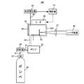
- FIG. 2 is a schematic diagram showing the configuration of the apparatus for producing the nanoparticle body 10 according to the embodiment of the present invention.
- the manufacturing apparatus 100 of the nanoparticle body 10 includes a cylinder 30, pipes 31 and 33, a pump 32, a cooler 34, a reaction vessel 35, a laser device 36, a lens 37, A heater 38, a thermocouple 39, a temperature detector 40, and a controller 41 are provided.
- the cylinder 30 is connected to a pump 32 by a pipe 31.
- the pump 32 is connected to the reaction vessel 35 by a pipe 33.
- the heater 38 is disposed in contact with the reaction vessel 35.
- One end of the thermocouple 39 is inserted into the reaction vessel 35 and the other end is connected to the temperature detector 40.
- the cylinder 30 stores gaseous carbon dioxide (CO 2 ).
- CO 2 gaseous carbon dioxide
- the piping 31 supplies CO 2 stored in the cylinder 30 to the pump 32 via the cooler 34.
- the pump 32 supplies the liquid CO 2 supplied from the cooler 34 via the pipe 31 into the reaction vessel 35 via the pipe 33.
- the pump 32 supplies a supercritical fluid composed of CO 2 via the CO 2 piping 33 so that the pressure generated in the reaction vessel 35 within the reaction vessel 35.
- the pipe 33 supplies CO 2 from the pump 32 into the reaction vessel 35.
- Cooler 34 for example, made from the ice, the CO 2 is cooled to a temperature at which CO 2 is CO 2 liquid gas output from the cylinder 30, and supplies the CO 2 in the cooled liquid to the pump 32.
- the reaction vessel 35 has a hollow cylindrical shape and is made of, for example, stainless steel.
- the reaction vessel 35 has sapphire windows 351 and 352 at both ends in the length direction.
- the reaction vessel 35 holds a molecular supercritical fluid made of CO 2 , a gold block 50, and the substrate 1.
- the laser device 36 is composed of, for example, an Nd: YAG laser, and emits laser light having a wavelength of 532 nm, which is a second harmonic of the Nd: YAG laser.
- This laser beam is composed of pulsed light having a pulse width of 10 nsec, a repetition frequency of 20 Hz, and a fluence of 0.9 J / cm 2 .
- the lens 37 condenses the laser beam emitted from the laser device 36 and irradiates the gold block 50 with the collected laser beam through the sapphire window 352. In this case, the lens 37 condenses the laser light so that the energy per pulse is changed from 19 mJ / pulse to 30 mJ / pulse.
- the gold bullion 50 has a flat plate shape.
- the heater 38 heats the reaction vessel 35 to a temperature at which CO 2 in the reaction vessel 35 becomes a molecular supercritical fluid in accordance with control from the controller 41.
- the thermocouple 39 detects an electromotive force due to the temperature of CO 2 in the reaction vessel 35 and outputs the detected electromotive force to the temperature detector 40.
- the temperature detector 40 receives an electromotive force from the thermocouple 39 and detects the temperature T of CO 2 based on the received electromotive force. Then, the temperature detector 40 outputs the detected temperature T to the controller 41.
- the controller 41 receives the temperature T from the temperature detector 40 and, based on the received temperature T, heats the reaction vessel 35 to a temperature Tc at which CO 2 in the reaction vessel 35 becomes a molecular supercritical fluid.
- the heater 38 is controlled.
- the pump 32 supplies CO 2 into the reaction vessel 35 so that the pressure in the reaction vessel 35 is in the range of 3 MPa to 9 MPa.
- the heater 38 heats the reaction container 35 so that the temperature T of CO 2 in the reaction container 35 is in the range of 36 to 40 ° C.
- the nanoparticle body 10 shown in FIG. 1 is generated. Becomes a molecular supercritical fluid.
- the gaseous CO 2 output from the cylinder 30 is cooled by the cooler 34 so as to become liquid CO 2.
- liquid CO 2 is more gaseous CO 2.
- the pressure of CO 2 in the reaction vessel 35 is easily set to a pressure of 3 MPa to 9 MPa by the pump 32 because it is easier to pressurize by the pump 32 than 2 . That is, it is for stably producing a molecular supercritical fluid composed of CO 2 .
- FIG. 3 is a process diagram showing a method for producing the nanoparticle body 10 shown in FIG. With reference to FIG. 3, when the manufacture of the nanoparticle body 10 is started, the substrate 1 and the gold block 50 are placed in the reaction vessel 35 (step S1).
- the cooler 34 cools the gaseous CO 2 to liquid CO 2 , and the pump 32 becomes the pressure at which the molecular supercritical fluid is generated in the reaction vessel 35 with the cooled liquid CO 2.
- the reaction vessel 35 is supplied (step S2). More specifically, the pump 32 supplies liquid CO 2 into the reaction vessel 35 so that the pressure in the reaction vessel 35 is in the range of 3 MPa to 9 MPa.
- thermocouple 39 detects an electromotive force due to the temperature of CO 2 in the reaction vessel 35, and outputs the detected electromotive force to the temperature detector 40.
- the temperature detector 40 detects the temperature T of CO 2 in the reaction vessel 35 based on the electromotive force received from the thermocouple 39, and outputs the detected temperature T to the controller 41.
- the controller 41 controls the heater 38 so that the temperature T received from the temperature detector 40 becomes the temperature Tc at which a molecular supercritical fluid made of CO 2 is generated. Then, the heater 38 heats the reaction vessel 35 so that the temperature T becomes the temperature Tc (step S3).
- the nano-sized gold that has jumped into the molecular supercritical fluid is deposited on the substrate 1.
- the laser device 36 stops the laser beam irradiation, and the heater 38 heats the reaction vessel 35 after 20 to 90 minutes have elapsed since the laser beam irradiation was stopped. Is stopped (step S5). Thereby, the manufacture of the nanoparticle body 10 is completed.
- the pressure of the molecular supercritical fluid is 30.3 MPa or more, only gold particles having a diameter of about 800 nm are produced, and gold particles to which the hair-like nanoparticle aggregate 22 is bonded as shown in FIG. 1 are not produced. is there.
- the pressure of the molecular supercritical fluid is about 0.1 MPa, only the hair-like nanoparticle aggregate 22 shown in FIG. 1 is produced and the head nanoparticle 21 is not produced.
- the laser device 36 condenses the laser beam by the lens 37 and irradiates the gold block 50 with the laser beam having an intensity of 19 mJ / pulse.
- the present invention is not limited to this, and the laser device 36 uses a laser beam having an intensity of about 12 mJ / pulse or more, which is a critical intensity at which laser ablation occurs in which nano-sized gold jumps from the gold block 50 into the molecular supercritical fluid. What is necessary is just to irradiate the gold block 50 through 37.
- the hair-like nanoparticle aggregate 22 having a hair-like shape is formed into the head nanoparticle 21 as shown in FIG. Medusa type nano-particles 2 having a structure adhered to the surface are manufactured.
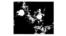
- FIG. 4 is a SEM (Scanning Electron Microscope) photograph of the medusa-type nanoparticle 2 shown in FIG.
- a white portion A having a nearly circular shape and white portions B arranged in a network around the white portion are observed.
- the white part A corresponds to the head nanoparticles 21 shown in FIG. 1, and the white part B corresponds to the hair-like nanoparticle aggregate 22 shown in FIG.
- FIG. 5 is an SEM photograph of the hair-like nanoparticle assembly 22 shown in FIG.
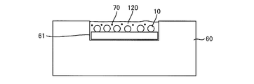
- FIG. 6 is a conceptual diagram of a sample for measuring the enhancement of the nanoparticle body 10 shown in FIG.
- a recess 61 is formed in a plate member 60 made of stainless steel, the nanoparticle body 10 is placed in the formed recess 61, and a liquid 120 to be inspected is further placed in the recess 61.
- the nanoparticle body 10 was irradiated with laser light, and the emission of the detection target 70 contained in the liquid 120 was observed.
- the recess 61 is covered with a cover glass during measurement.
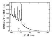
- FIG. 7 is a diagram showing the relationship between fluorescence and Raman intensity and wavelength.
- the vertical axis represents fluorescence and Raman intensity
- the horizontal axis represents wavelength.
- a straight line k1 indicates the relationship between the fluorescence and Raman intensity of the crystal violet molecule and the wavelength
- a curve k2 indicates the relationship between the fluorescence and Raman intensity of the nanoparticle body 10 and the crystal violet molecule and the wavelength.
- the fluorescence and Raman intensity were measured under the following conditions.
- the laser beam is a He—Ne laser having a wavelength of 632.8 nm.
- the intensity of the laser beam is 2.83 ⁇ W.
- the intensity of 2.83 ⁇ W corresponds to the intensity of 1/300 of the laser pointer.
- the measurement time is 1 second (2 times average).
- the solution concentration is 3.6 ⁇ 10 ⁇ 6 mol / l.
- the spike-like signal is the Raman spectrum of the crystal violet molecule
- the baseline-like signal is the fluorescence spectrum of the crystal violet molecule
- the presence of the nanoparticle body 10 containing nano-sized gold particles enhances the fluorescence and Raman intensity of the crystal violet molecule, and dramatically increases the Raman intensity of the crystal violet molecule.
- the increase in Raman intensity was determined as follows.
- the Raman intensity is calculated by subtracting the fluorescence intensity from the fluorescence and Raman intensity. Then, the calculated Raman intensity is corrected by the sample volume. This process is performed for the fluorescence and Raman intensity (straight line k1) of only the crystal violet molecule and the fluorescence and Raman intensity (curve k2) of the nanoparticle body 10 and the crystal violet molecule.
- the ratio of the Raman intensity of the crystal violet molecule thus obtained to the Raman intensity of the nanoparticle body 10 and the crystal violet molecule was taken as the Raman enhancement.
- the Raman intensity measurement target is not limited to the crystal violet molecule, but may be any of rhodamine molecules, malachite green molecules, Nile blue molecules, and adenine molecules (DNA bases).
- the Raman intensity of only malachite green molecules when measuring the Raman intensity of only malachite green molecules, repeating the measurement for 2 hours continuously is repeated 5 times.
- the measurement for 6 seconds is repeated 100 times, or the measurement for 2 minutes is repeated 6 times.
- the Raman intensity of only the crystal violet molecule when measuring the Raman intensity of only the crystal violet molecule, it is continuously measured for 10 minutes, and this is repeated 100 times.
- the Raman intensity is measured by changing the time according to the measurement object. As described above, the Raman intensity cannot be obtained unless it is measured for a long time, or sufficient Raman intensity cannot be obtained even if the measurement is performed for a long time.
- the measurement of the Raman intensity of any one of the crystal violet molecule, rhodamine molecule, malachite green molecule, Nile blue molecule and adenine molecule (DNA base) and the nanoparticle body 10 can obtain sufficient Raman intensity in 1 second. Can do.
- the nanoparticle body 10 it is possible to drastically shorten the Raman intensity measurement time and obtain an analysisable intensity.
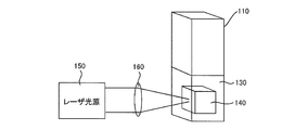
- FIG. 8 is a diagram for explaining a method for producing an aqueous solution of nanoparticles made of silicon.
- water 130 is put into a glass container 110, and silicon lump 140 is put into the water 130.
- the pressure of the container 110 is atmospheric pressure, and the temperature is room temperature.
- an organic solvent such as alcohol or hydrocarbon is put into a glass container 110, and silicon powder is put into the liquid.
- the liquid is obtained by stirring with a magnetic stirrer and removing unproduct by a centrifuge.
- the pressure of the container 110 is atmospheric pressure, and the temperature is room temperature.
- the silicon mass 140 is irradiated with a laser beam of 532 nm from the laser light source 150 through the condenser lens 160.
- silicon having a nano-sized particle size jumps out into the water 130 and is dispersed in the water 130 by laser ablation.
- silicon having a nano-sized particle size is dispersed in an organic solvent such as alcohol or hydrocarbon.
- an aqueous solution of nanoparticles made of silicon is produced by laser ablation of silicon in water at normal temperature and normal pressure.
- a dispersion solution of nanoparticles composed of silicon is also produced by laser ablation of silicon in an organic solvent such as alcohol and hydrocarbon at normal temperature and normal pressure.
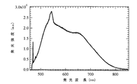
- FIG. 9 is a diagram showing the relationship between the emission intensity of photoluminescence and the emission wavelength.
- the vertical axis represents the emission intensity
- the horizontal axis represents the emission wavelength.
- the excitation wavelength of photoluminescence is 458 nm.
- the relationship between the emission intensity and the emission wavelength of the photoluminescence shown in FIG. 9 is that water 130 containing silicon nanoparticles produced by the method shown in FIG. 8 is transferred to the recess 61 instead of the liquid 120 shown in FIG. It was measured by putting it in.
- a nanoparticle made of silicon emits light in a wavelength region of about 470 nm to 830 nm and has a peak wavelength of emission at about 545 nm.
- the emission intensity of the nanoparticles is enhanced by about 600,000 times, and when the photoluminescence excitation wavelength is set to 515 nm, the emission intensity of the nanoparticles is about 3 It was enhanced 10,000 times.
- the emission of the silicon nanoparticle was remarkably increased by the huge enhanced electric field.
- the nanoparticle body 10 significantly increases the emission intensity of silicon due to its huge enhanced electric field when excited by light.
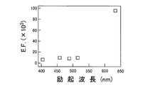
- FIG. 10 is a diagram showing the relationship between the emission enhancement of photoluminescence and the excitation wavelength.
- the vertical axis represents the emission enhancement of photoluminescence
- the horizontal axis represents the excitation wavelength.
- the emission enhancement was calculated by the following method. Sample I including silicon nanoparticle solution and nanoparticle body 10, Sample II including only silicon nanoparticle solution and substrate 1 of nanoparticle body 10, Sample III including nanoparticle body 10 and solvent, solvent and nano A sample IV including only the substrate 1 of the particle body 10 is prepared.
- photoluminescence is measured for each of these four types of samples I to IV. Assuming that the photoluminescence intensities of the samples I to IV are I PL1 to I PL4 , respectively, the light emission enhancement intensity is calculated by (I PL1 ⁇ I PL3 ) / (I PL2 ⁇ I PL4 ).
- the emission intensity of silicon nanoparticles was enhanced by nanoparticle body 10 in the excitation wavelength range of 400 nm to 650 nm. This is because when the hair-like nanoparticle aggregate 22 of the nanoparticle body 10 has a branched structure, a portion where the interval between the single nanoparticles 221 is about nano increases. Therefore, it was found that the light-emitting intensity of the photoluminescence is enhanced by the hair-like nanoparticle aggregate 22 having a branched structure.
- FIG. 11 is a conceptual diagram of another nanoparticle body according to the embodiment of the present invention.
- the nanoparticle body according to the embodiment of the present invention may be a nanoparticle body 10A shown in FIG.
- nanoparticle body 10A is obtained by adding amino group 23 to nanoparticle body 10 shown in FIG. 1, and is otherwise the same as nanoparticle body 10.
- the amino group 23 adheres to the surface of the substrate 1 and adsorbs the head nanoparticles 21 (gold particles).
- the nanoparticle body 10A may include a thiol group instead of the amino group 23.
- the thiol group adheres to the surface of the substrate 1 like the amino group 23 and adsorbs the head nanoparticles 21 (gold particles).
- the amino group 23 and the thiol group constitute a “functional group”.
- FIG. 12 is a conceptual diagram of still another nanoparticle body according to the embodiment of the present invention.
- the nanoparticle body according to the embodiment of the present invention may be a nanoparticle body 10B shown in FIG. Referring to FIG. 12, nanoparticle body 10 ⁇ / b> B is the same as nanoparticle body 10 except that substrate 1 of nanoparticle body 10 shown in FIG. 1 is deleted.
- the nanoparticle body 10B is manufactured according to the process diagram shown in FIG. 3 using the manufacturing apparatus 100 shown in FIG. In this case, in step S ⁇ b> 1, the substrate 1 is not installed in the reaction container 35, and only the gold block 50 is installed in the reaction container 35. Then, the above-described steps S2 to S5 are sequentially performed to manufacture the nanoparticle body 10B.
- the nanoparticle body according to the embodiment of the present invention may not include the substrate 1.
- FIG. 13 is a diagram showing the relationship between the Raman intensity and the Raman shift.
- the vertical axis represents the Raman intensity
- the horizontal axis represents the Raman shift.
- Curve k3 shows the relationship between Raman intensity and Raman shift of Nile Blue when the nanoparticle body 10B is used as an enhancement substrate
- curve k4 shows the Raman intensity and Raman shift of the hair-like nanoparticle aggregate 22 only.
- the curve k5 shows the relationship between the Raman intensity of only the head nanoparticles 21 and the Raman shift.
- the Raman intensity was determined by spin coating a gold nanoparticle with a Nile blue solution with a concentration of 1.02 ⁇ 10 ⁇ 6 mol / l, and reducing the laser light with an excitation wavelength of 632.8 nm with an ND filter. The measurement was performed under the conditions of 200 ⁇ m, measurement time 2 seconds ⁇ 15, diffraction grating (groove number 150), ⁇ 100 objective lens, and laser diameter 1.5 ⁇ m.
- nanoparticle body 10B, hair-like nanoparticle assembly 22 and head nanoparticle 21 have a peak in the vicinity of 595 (cm ⁇ 1 ).
- the nanoparticle body 10 ⁇ / b> B has a dramatically higher Raman intensity than the hair-like nanoparticle aggregate 22 and the head nanoparticle 21.
- FIG. 14 is a diagram showing the particle size distribution of the head nanoparticles 21 and the single nanoparticles 221.
- FIG. FIG. 14A shows the particle size distribution of the single nanoparticle 221
- FIG. 14B shows the particle size distribution of the head nanoparticle 21.
- the particle size of the single nanoparticle 221 is distributed in the range of 10 nm to 100 nm.
- the number of single nanoparticles 221 having a particle size of 30 nm is the largest, and the number of single nanoparticles 221 having a particle size larger than 30 nm or smaller than 30 nm has a particle size of 30 nm. The number is smaller than the number of single nanoparticles 221.
- the particle size of the head nanoparticles 21 is distributed in the range of 200 nm to 1200 nm.
- the head nanoparticles 21 have a large particle size distribution in the range of 300 nm to 900 nm.
- the head nanoparticles 21 have a particle size of 200 nm to 1200 nm
- the single nanoparticles 221 have a particle size of 10 nm to 100 nm.
- the ratio between the particle size of the head nanoparticles 21 and the particle size of the single nanoparticles 221 is 2 to 120.
- the length of the hair-like nanoparticle aggregate 22 is 0.01 ⁇ m to 100 ⁇ m.
- substrate 1 is preferably used, and substrate 1 is preferably as described above. And glass or glass / ITO.
- the nanoparticle bodies 10 and 10A having a structure in which the hair-like nanoparticle aggregate 22 is bonded to the head nanoparticle 21 cannot be obtained.
- FIG. 15 is a schematic view of an analyzer using the nanoparticle body 10 shown in FIG.
- analysis apparatus 300 includes nanoparticle body 310, sample stage 320, laser light source 330, beam splitter 340, reflection mirror 350, objective lens 360, filter 370, and monochromator 380. And a personal computer (PC: 390).
- PC personal computer
- the nanoparticle body 310 includes any one of the nanoparticle body 10 shown in FIG. 1, the nanoparticle body 10A shown in FIG. 10, and the nanoparticle body 10B shown in FIG.
- the nanoparticle body 310 is disposed in the recess 321 of the sample stage 320.
- the sample stage 320 has a recess 321 and holds the nanoparticle body 310.
- the beam splitter 340 transmits the laser beam from the laser light source 330 as it is to the reflection mirror 350 and guides the light received from the reflection mirror 350 to the filter 370.
- the reflection mirror 350 reflects the laser light from the beam splitter 340 toward the objective lens 360 and reflects the light from the objective lens 360 toward the beam splitter 340.
- the objective lens 360 condenses the laser beam received from the reflection mirror 350 and irradiates the nanoparticle body 310 with the collected laser beam.
- the objective lens 360 receives light emitted from the detection target and transmits the received light to the reflection mirror 350.
- the filter 370 receives light from the beam splitter 340 and passes light in a desired wavelength region out of the received light to the monochromator 380.
- the monochromator 380 separates the light received from the filter 370 into components of each wavelength, and outputs the separated components of each wavelength to the PC 390.
- PC 390 analyzes the detection target contained in the liquid to be inspected based on the component of each wavelength received from the monochromator 380.
- the liquid 400 containing the detection target is placed in the recess 321 of the sample stage 320.
- the nanoparticle body 310 is immersed in the liquid 400.
- the nanoparticle body 310 and the liquid 400 are irradiated.
- the enhancement of the emission intensity due to a single nanoparticle 221 ( gold particles), as described above, and 10 9.
- the emitted Raman scattered light reaches the beam splitter 340 via the objective lens 360 and the reflection mirror 350 and is guided to the filter 370 by the beam splitter 340.
- the filter 370 passes light in a desired wavelength region out of the Raman scattered light received from the beam splitter 340 to the monochromator 380, and the monochromator 380 separates the light received from the filter 370 into each wavelength component. Then, the separated components of each wavelength are output to the PC 390.
- the PC 390 analyzes what the detection target is based on the components of each wavelength received from the monochromator 380.
- the number of molecules of the detection target in the liquid 400 is about 10 ⁇ 20 mol.
- This 10 ⁇ 20 mol means that 1 drop of drug is dropped into a 25 m pool, the pool is stirred, 1 drop is taken from there, 1 drop is dropped into another 25 m pool, and 1 drop is taken from that pool. It is the number that is contained in the droplet.
- the laser light source 330 emits laser light having an intensity about 1/300 that of a commercially available laser pointer.
- the overall size of the analyzer 300 is about the same as a notebook personal computer.
- the analysis apparatus 300 can detect the detection target from the liquid 400 having a very low concentration using a very weak laser beam. Moreover, the analyzer 300 can be easily carried.
- the analysis apparatus 300 uses liquids, solutions, sols, gels, high pressure liquids, high pressure gases, and supercritical fluids as inspection targets.
- the inspection object is a high-pressure gas, a high-pressure liquid, and a supercritical fluid
- a high-pressure resistant container that can accommodate the high-pressure gas, high-pressure liquid, and supercritical fluid is used.
- the molecular supercritical fluid used to produce the nanoparticle bodies 10, 10A, and 10B has been described as being CO 2. However, in the embodiment of the present invention, the present invention is not limited to this, and the nanoparticle body is not limited thereto.
- the molecular supercritical fluid for producing 10, 10A, 10B may be any of CHF 3 , SF 6 , and Ar.
- the temperature for obtaining a molecular supercritical fluid is 30 to 40 ° C. (typical temperature: 32.1 ° C.) in the case of CHF 3 , and 45 to 55 ° C. (typical temperature: 52 .2 ° C. in the case of SF 6 ). 0 ° C.), and in the case of Ar, it is 20 to 30 ° C. (typical temperature: normal temperature).
- the temperature is lower than the temperature (200 ° C. to 300 ° C.) when using any of water, ethanol, and alcohol.
- a critical fluid can be obtained.
- the supercritical fluid may be other than the molecular supercritical fluid.
- FIG. 16 is a transmission electron micrograph of a nanoparticle produced using a molecular supercritical fluid composed of CHF 3 .
- the medusa-type nanoparticles include head nanoparticles and a plurality of hair-like nanoparticle aggregates.
- the hair-like nanoparticle aggregate has a structure in which a plurality of nanoparticles are connected in a bead shape.
- assembly has a particle size smaller than a head nanoparticle.
- the head nanoparticles 21 and the single nanoparticles 221 of the nanoparticle bodies 10, 10A, and 10B are made of gold.
- the head nanoparticles 21 and the single nanoparticles 221 of the particle bodies 10, 10A, 10B may be made of any of silver, copper, platinum, aluminum, and palladium, and are gold, silver, copper, platinum, aluminum, and You may consist of 2 or more types of mixtures selected from the group which consists of palladium.
- the head nanoparticles 21 and the single nanoparticles 221 of the nanoparticle bodies 10, 10A, and 10B may generally be made of a metal that exhibits surface plasmon resonance, and the shape thereof is spherical. I just need it.
- the nanoparticle bodies 10, 10A, 10B are manufactured using the manufacturing apparatus 100 shown in FIG. the conditions, temperature to obtain a molecule with supercritical fluid, consisting CO 2 is 37.1 ° C., a pressure in order to obtain a molecular supercritical fluid consisting of CO 2 is 4.29MPa, the laser beam The intensity is 760 mW, the pulse repetition frequency is 20 Hz, the energy per pulse is 38 mJ / pulse, and the laser light irradiation time is 5 minutes.
- the head nanoparticles 21 constitute “first nanoparticles”, and the single nanoparticles 221 constitute “second nanoparticles”.
- the sample stage 320 constitutes a “container”, and the monochromator 380 and the PC 390 constitute an “analyzer”.
- the present invention is applied to a nanoparticle body, a manufacturing method thereof, and an analyzer using the nanoparticle body.
Landscapes
- Chemical & Material Sciences (AREA)
- Engineering & Computer Science (AREA)
- Nanotechnology (AREA)
- Inorganic Chemistry (AREA)
- Physics & Mathematics (AREA)
- Composite Materials (AREA)
- Condensed Matter Physics & Semiconductors (AREA)
- General Physics & Mathematics (AREA)
- Materials Engineering (AREA)
- Crystallography & Structural Chemistry (AREA)
- Investigating, Analyzing Materials By Fluorescence Or Luminescence (AREA)
Abstract
【課題】光強度または電場の増強度を大きくできるナノ粒子体を提供する。 【解決手段】ナノ粒子体(10)は、基板(1)と、複数のメデューサ型ナノ粒子(2)とを備える。基板(1)は、例えば、ガラスからなる。複数のメデューサ型ナノ粒子(2)は、基板(1)の表面に配置される。複数のメデューサ型ナノ粒子(2)の各々は、頭部ナノ粒子(21)と、複数の毛髪状ナノ粒子集合体(22)とを含む。頭部ナノ粒子(21)は、例えば、金からなり、800nmの直径を有する。そして、頭部ナノ粒子(21)は、基板1上に配置される。複数の毛髪状ナノ粒子集合体(22)の各々は、毛髪状の形状を有し、一方端が頭部ナノ粒子(21)に接着している。そして、複数の毛髪状ナノ粒子集合体(22)の各々は、複数の単一ナノ粒子(221)からなる。複数の単一ナノ粒子(221)の各々は、例えば、金からなり、30nmの直径を有する。そして、複数の単一ナノ粒子(221)は、数珠状に繋がっており、枝分かれ構造を有する。
Description
この発明は、ナノ粒子体、その製造方法、およびナノ粒子体を用いた分析装置に関するものである。
近年、貴金属ナノ粒子の生成が化学、物理、工学および医薬をはじめ、非常に多くの分野で注目されている。これらの分野は、プラズモニクスと呼ばれ、新領域の学問体系を作り始めている。
このように、貴金属ナノ粒子の分野が大きく発展している主な理由は、貴金属がナノサイズになると、光を反射するのではなく、光を吸収または散乱し、その結果、ナノ領域に巨大電場を形成することによる。そして、貴金属からなるナノサイズの粒子にレーザ光を照射すると、巨大な増強電場が生成され、ラマン分光法における発光の光強度が増強される。特に、複数の銀ナノ粒子が接近してくると、単一銀ナノ粒子と比べて、大きな増強の出現が理論的に検証されている(非特許文献1,2)。
Kuiru Li, Mark I. Stockman, and David J. Bergman, "Self-Similar Chain of Metal Nanospheres as an Efficient Nanolens," PHYSICAL REVIEW LETTERS, Vol. 91, No. 22, 28 November 2003.
齋藤健一、南孝将、山村知玄、加治屋大介,"金ナノネックレスと巨大金ナノ球の創製とその生成メカニズム,"第一回分子科学討論会2007 3P037.
しかし、従来の貴金属からなるナノ粒子を用いた場合、発光や散乱光の光強度または電場の増強度が低いという問題がある。
そこで、この発明は、かかる問題を解決するためになされたものであり、その目的は、光強度または電場の増強度を大きくできるナノ粒子体を提供することである。
また、この発明の別の目的は、光強度または電場の増強度を大きくできるナノ粒子体の製造方法を提供することである。
更に、この発明の別の目的は、光強度または電場の増強度を大きくできるナノ粒子体を用いた分析装置を提供することである。
この発明の実施の形態によれば、ナノ粒子体は、第1のナノ粒子と、ナノ粒子集合体とを備える。ナノ粒子集合体は、一方端が第1のナノ粒子の表面に接着し、第1のナノ粒子よりも粒径が小さい第2のナノ粒子同士が複数個数珠状に繋がっている。
また、この発明の実施の形態によれば、ナノ粒子体の製造方法は、請求項1から請求項8のいずれかに記載のナノ粒子体を製造する製造方法であって、超臨界流体中に金属塊を保持する第1の工程と、超臨界流体の圧力を大気圧よりも高く、かつ、300気圧よりも低い圧力に設定する第2の工程と、第1および第2のナノ粒子が金属塊から超臨界流体中へ飛び出すレーザアブレーションが生じる強度を有するレーザ光を金属塊に照射する第3の工程とを備える。
更に、この発明の実施の形態によれば、分析装置は、容器と、ナノ粒子体と、レーザ光源と、分析器とを備える。容器は、検査対象の液体、溶液、ゾル、ゲル、高圧液体、高圧気体および超臨界流体を入れる。ナノ粒子体は、容器中に保持される。レーザ光源は、容器内のナノ粒子体にレーザ光を照射する。分析器は、液体が容器内に入れられた状態で容器内において発光や散乱光を検出するとともに、その検出した光の波長を分析して液体中に含まれる検出対象物を分析する。ナノ粒子体は、基板と、ナノ粒子とを含む。ナノ粒子は、基板上に配置され、金からなる。ナノ粒子は、第1のナノ粒子と、ナノ粒子集合体とを含む。第1のナノ粒子は、基板上に配置され、第1の粒径を有する。ナノ粒子集合体は、一方端が第1のナノ粒子の表面に接着した毛髪状の形状からなる。そして、ナノ粒子集合体は、各々が第1の粒径よりも小さい第2の粒径を有し、数珠状に繋がれた複数の第2のナノ粒子を含む。そして、複数の第2のナノ粒子は、複数に枝分かれしたブランチ構造を含む。
この発明の実施の形態によれば、ナノ粒子体は、一方端が第1のナノ粒子の表面に接着した毛髪状のナノ粒子集合体を有し、ナノ粒子集合体は、第1のナノ粒子よりも小さい直径を有する第2のナノ粒子が数珠状に繋がった構造からなる。その結果、レーザ光がナノ粒子集合体に照射されると、第1および第2のナノ粒子は、プラズモンバンドが光励起されたり、近接場の生成により、増強電場を発生する。そして、第1および第2のナノ粒子に近接して存在する他の物質は、レーザ光によって励起されるとともに、第1および第2のナノ粒子が発生した増強電場によって発光強度が増強された光を発する。更に、ブランチ構造がより多くの近接部分を生み、増強された光を発する。
従って、ナノ粒子体によって光強度の増強度を大きくできる。
本発明の実施の形態について図面を参照しながら詳細に説明する。なお、図中同一または相当部分には同一符号を付してその説明は繰返さない。
図1は、この発明の実施の形態によるナノ粒子体の概念図である。図1を参照して、この発明の実施の形態によるナノ粒子体10は、基板1と、複数のメデューサ型ナノ粒子2とを備える。基板1は、例えば、ガラス、およびITO/ガラスのいずれかからなる。複数のメデューサ型ナノ粒子2は、基板1の表面に配置される。
複数のメデューサ型ナノ粒子2の各々は、頭部ナノ粒子21と、複数の毛髪状ナノ粒子集合体22とを含む。頭部ナノ粒子21は、例えば、金からなり、800nmの粒径を有する。そして、頭部ナノ粒子21は、基板1の表面に接して配置される。
複数の毛髪状ナノ粒子集合体22の各々は、毛髪状の形状を有し、一方端が頭部ナノ粒子21に接着している。そして、複数の毛髪状ナノ粒子集合体22の各々は、複数の単一ナノ粒子221からなる。複数の単一ナノ粒子221の各々は、例えば、金からなり、30nmの粒径を有する。そして、複数の単一ナノ粒子221は、数珠状に繋がっている。なお、図1においては、数珠状に繋がった複数の単一ナノ粒子221は、枝分かれ構造を有する。
図2は、この発明の実施の形態によるナノ粒子体10の製造装置の構成を示す概略図である。図2を参照して、ナノ粒子体10の製造装置100は、ボンベ30と、配管31,33と、ポンプ32と、冷却器34と、反応容器35と、レーザ装置36と、レンズ37と、ヒータ38と、熱電対39と、温度検出器40と、制御器41とを備える。
ボンベ30は、配管31によってポンプ32に接続される。ポンプ32は、配管33によって反応容器35に接続される。ヒータ38は、反応容器35に接して配置される。熱電対39は、一方端側が反応容器35内に挿入され、他方端が温度検出器40に接続される。
ボンベ30は、気体の二酸化炭素(CO2)を収納する。配管31は、ボンベ30に収納されたCO2を冷却器34を介してポンプ32へ供給する。ポンプ32は、配管31を介して冷却器34から供給された液体のCO2を配管33を介して反応容器35内へ供給する。この場合、ポンプ32は、CO2からなる超臨界流体が反応容器35内で生成される圧力になるようにCO2を配管33を介して反応容器35内へ供給する。
配管33は、ポンプ32からのCO2を反応容器35内に供給する。冷却器34は、たとえば、氷からなり、ボンベ30から出力された気体のCO2が液体のCO2になる温度にCO2を冷却し、その冷却した液体のCO2をポンプ32に供給する。
反応容器35は、中空の円筒形状を有し、たとえば、ステンレスからなる。そして、反応容器35は、長さ方向の両端部にサファイア窓351,352を有する。また、反応容器35は、CO2からなる分子性超臨界流体と、金塊50と、基板1とを保持する。
レーザ装置36は、たとえば、Nd:YAGレーザからなり、Nd:YAGレーザの2倍波である532nmの波長を有するレーザ光を出射する。このレーザ光は、パルス幅が10nsecであり、繰返し周波数が20Hzであり、フルーエンスが0.9J/cm2であるパルス光からなる。
レンズ37は、レーザ装置36から出射されたレーザ光を集光し、その集光したレーザ光をサファイア窓352を介して金塊50に照射する。この場合、レンズ37は、1パルス当たりのエネルギーが19mJ/パルスから30mJ/パルスになるようにレーザ光を集光する。また、金塊50は、平板形状からなる。
ヒータ38は、制御器41からの制御に従って、反応容器35内のCO2が分子性超臨界流体になる温度に反応容器35を加熱する。熱電対39は、反応容器35内のCO2の温度に起因する起電力を検出し、その検出した起電力を温度検出器40へ出力する。
温度検出器40は、熱電対39から起電力を受け、その受けた起電力に基づいて、CO2の温度Tを検出する。そして、温度検出器40は、その検出した温度Tを制御器41へ出力する。
制御器41は、温度検出器40から温度Tを受け、その受けた温度Tに基づいて、反応容器35内のCO2が分子性超臨界流体になる温度Tcに反応容器35を加熱するようにヒータ38を制御する。
この発明の実施の形態においては、反応容器35内の圧力が3MPa~9MPaの範囲になるように、ポンプ32は、CO2を反応容器35内に供給する。また、ヒータ38は、反応容器35内のCO2の温度Tが36~40℃の範囲になるように反応容器35を加熱する。
そして、反応容器35内の圧力が3MPa~9MPaの範囲になり、反応容器35内のCO2の温度Tが36~40℃の範囲になれば、図1に示すナノ粒子体10が生成される分子性超臨界流体になる。
また、製造装置100においては、ボンベ30から出力された気体のCO2を液体のCO2になるように冷却器34によって冷却しているが、これは、液体のCO2の方が気体のCO2よりもポンプ32によって加圧し易いため、反応容器35内のCO2の圧力をポンプ32によって3MPa~9MPaの圧力に設定し易くするためである。つまり、CO2からなる分子性超臨界流体を安定して作り出すためである。
図3は、図1に示すナノ粒子体10の製造方法を示す工程図である。図3を参照して、ナノ粒子体10の製造が開始されると、基板1および金塊50が反応容器35内に設置される(ステップS1)。
そして、冷却器34は、気体のCO2を液体のCO2に冷却し、ポンプ32は、その冷却された液体のCO2を反応容器35内で分子性超臨界流体が生成される圧力になるように反応容器35へ供給する(ステップS2)。より具体的には、ポンプ32は、反応容器35内の圧力が3MPa~9MPaの範囲になるように液体のCO2を反応容器35内へ供給する。
その後、熱電対39は、反応容器35内のCO2の温度に起因する起電力を検出し、その検出した起電力を温度検出器40へ出力する。温度検出器40は、熱電対39から受けた起電力に基づいて、反応容器35内のCO2の温度Tを検出し、その検出した温度Tを制御器41へ出力する。
制御器41は、温度検出器40から受けた温度Tが、CO2からなる分子性超臨界流体が生成される温度Tcになるようにヒータ38を制御する。そして、ヒータ38は、温度Tが温度Tcになるように反応容器35を加熱する(ステップS3)。
引き続いて、レーザ装置36は、レーザアブレーションが生じる強度(=19mJ/パルス)を有するレーザ光をレンズ37を介して金塊50に照射する(ステップS4)。これによって、レーザアブレーションが起こり、ナノサイズの金が金塊50から分子性超臨界流体(=CO2)中へ飛び出す。そして、分子性超臨界流体中へ飛び出したナノサイズの金は、基板1上に堆積される。
レーザ光の照射時間が所望の時間になると、レーザ装置36は、レーザ光の照射を停止し、ヒータ38は、レーザ光の照射が停止されてから20~90分経過後、反応容器35の加熱を停止する(ステップS5)。これによって、ナノ粒子体10の製造が終了する。
なお、ステップS2においては、分子性超臨界流体の圧力は、3MPa~9MPaの範囲に設定されたが、一般的には、0.1MPaよりも高く、かつ、30.3MPa(=300気圧)よりも低い圧力であればよい。分子性超臨界流体の圧力が30.3MPa以上になると、直径が800nm程度の金粒子のみが製造され、図1に示すような毛髪状ナノ粒子集合体22が接着した金粒子が製造されないからである。一方、分子性超臨界流体の圧力が0.1MPa程度では、図1に示す毛髪状ナノ粒子集合体22のみが製造され、頭部ナノ粒子21が製造されないからである。
また、図3に示す工程においては、レーザ装置36は、レーザ光をレンズ37によって集光し、19mJ/パルスの強度を有するレーザ光を金塊50に照射すると説明したが、この発明の実施の形態においては、これに限らず、レーザ装置36は、ナノサイズの金が金塊50から分子性超臨界流体中へ飛び出すレーザアブレーションが生じる臨界強度である約12mJ/パルス以上の強度を有するレーザ光をレンズ37を介して金塊50に照射するものであればよい。
上述したように、反応容器35内の圧力を3MPa~9MPaの圧力範囲に設定することによって、図1に示すように、毛髪状の形状からなる毛髪状ナノ粒子集合体22が頭部ナノ粒子21の表面に接着した構造からなるメデューサ型ナノ粒子2が製造される。
図4は、図1に示すメデューサ型ナノ粒子2のSEM(Scanning Electron Microscope)写真である。
図4を参照して、円形に近い形状からなる白い部分Aと、その白い部分の周囲にネットワーク状に配置された白い部分Bとが観測される。
白い部分Aは、図1に示す頭部ナノ粒子21に相当し、白い部分Bは、図1に示す毛髪状ナノ粒子集合体22に相当する。
図5は、図1に示す毛髪状ナノ粒子集合体22のSEM写真である。図5を参照して、毛髪状ナノ粒子集合体22は、直径が30nm程度であるナノ粒子(=金)が数珠状に繋がった構造からなる。更に、数珠状に繋がった構造は、枝分かれ構造を有する。
図6は、図1に示すナノ粒子体10の増強度を測定するための試料の概念図である。図6を参照して、ステンレスからなる板部材60に、凹部61を形成し、その形成した凹部61中にナノ粒子体10を入れ、更に、検査対象の液体120を凹部61に入れる。
そして、ナノ粒子体10にレーザ光を照射し、液体120に含まれる検出対象物70の発光を観測した。なお、液体120の蒸発を防止するために、測定中は、凹部61は、カバーガラスによって覆われている。
図7は、蛍光およびラマン強度と波長との関係を示す図である。図7において、縦軸は、蛍光およびラマン強度を表し、横軸は、波長を表す。また、直線k1は、クリスタルバイオレット分子の蛍光およびラマン強度と波長との関係を示し、曲線k2は、ナノ粒子体10およびクリスタルバイオレット分子の蛍光およびラマン強度と波長との関係を示す。
なお、蛍光およびラマン強度の測定は、次の条件により行なわれた。レーザ光は、632.8nmの波長を有するHe-Neレーザである。また、レーザ光の強度は、2.83μWである。この2.83μWの強度は、レーザポインタの300分の1の強度に相当する。測定時間は、1秒(2回平均)である。更に、溶液濃度は、3.6×10⁻⁶mol/lである。
図7を参照して、クリスタルバイオレット分子のみの蛍光およびラマン強度は、非常に弱い(直線k1参照)。
一方、ナノ粒子体10およびクリスタルバイオレット分子の蛍光およびラマン強度は、非常に強い(曲線k2参照)。
曲線k2において、スパイク状の信号は、クリスタルバイオレット分子のラマンスペクトルであり、ベースライン状の信号は、クリスタルバイオレット分子の蛍光スペクトルである。
このように、ナノサイズの金粒子を含むナノ粒子体10が存在することにより、クリスタルバイオレット分子の蛍光およびラマン強度は、増強され、クリスタルバイオレット分子のラマン強度は、飛躍的に増強される。
ラマン強度の増強度は、次のように求められた。蛍光およびラマン強度から蛍光強度を差し引いて、ラマン強度を算出する。そして、その算出したラマン強度を試料の体積によって補正する。この処理をクリスタルバイオレット分子のみの蛍光およびラマン強度(直線k1)と、ナノ粒子体10およびクリスタルバイオレット分子の蛍光およびラマン強度(曲線k2)とについて行なう。
そして、このようにして得られたクリスタルバイオレット分子のみのラマン強度とナノ粒子体10およびクリスタルバイオレット分子のラマン強度との比をラマンの増強度とした。
その結果、109の増強度が得られた。従って、ナノ粒子体10は、クリスタルバイオレット分子のラマン強度を飛躍的に増強させることが実証された。
なお、ラマン強度の測定対象物は、クリスタルバイオレット分子に限らず、ローダミン分子、マラカイトグリーン分子、ナイルブルー分子およびアデニン分子(DNAの塩基)のいずれかであってもよい。
そして、例えば、マラカイトグリーン分子のみのラマン強度を測定する場合、連続して2時間測定することを5回繰り返し行なう。また、ナイルブルー分子のみのラマン強度を測定する場合、6秒の測定を100回繰り返し行ない、または、2分の測定を6回繰り返し行なう。更に、クリスタルバイオレット分子のみのラマン強度を測定する場合、連続して10分測定し、これを100回繰り返し行う。更に、ローダミン分子、およびアデニン分子(DNAの塩基)のみのラマン強度を測定する場合も、測定の対象物に応じて時間を変えてラマン強度を測定する。このように、長時間を掛けて測定しないと、ラマン強度を得ることができない、または長時間かけて測定しても、十分なラマン強度は得られない。
一方、クリスタルバイオレット分子、ローダミン分子、マラカイトグリーン分子、ナイルブルー分子およびアデニン分子(DNAの塩基)のいずれかと、ナノ粒子体10とのラマン強度の測定は、1秒で十分なラマン強度を得ることができる。
従って、ナノ粒子体10を用いることによって、ラマン強度の測定時間を飛躍的に短縮し、分析可能な強度を得ることができる。
図8は、シリコンからなるナノ粒子の水溶液を製造する方法を説明するための図である。図8を参照して、ガラス製の容器110に水130を入れ、その水130の中にシリコン塊140を入れる。この場合、容器110の圧力は、大気圧であり、温度は、室温である。または、ガラス製の容器110にアルコールや炭化水素などの有機溶媒を入れ、その液体中にシリコン粉末を入れる。液体は、マグネチックスターラーで攪拌し、未生成物を遠心分離器で除去して得られる。この場合、容器110の圧力は、大気圧であり、温度は、室温である。
そして、レーザ光源150から集光レンズ160を介して532nmのレーザ光をシリコン塊140に照射する。
そうすると、レーザアブレーションによって、ナノサイズの粒径を有するシリコンが水130中へ飛び出し、水130中に分散する。同様に、アルコールや炭化水素などの有機溶媒にもナノサイズの粒径を有するシリコンが分散する。
このように、シリコンからなるナノ粒子の水溶液は、常温および常圧下の水中におけるシリコンのレーザアブレーションによって製造される。同様に、シリコンからなるナノ粒子の分散溶液は、常温および常圧下におけるアルコールや炭化水素などの有機溶媒中におけるシリコンのレーザーアブレーションにおいても製造される。
図9は、フォトルミネッセンスの発光強度と発光波長との関係を示す図である。図9において、縦軸は、発光強度を表し、横軸は、発光波長を表す。そして、フォトルミネッセンスの励起波長は、458nmである。また、図9に示すフォトルミネッセンスの発光強度と発光波長との関係は、図8に示す方法によって製造されたシリコンからなるナノ粒子を含む水130を図7に示す液体120の代わりに凹部61に入れて測定されたものである。
図9を参照して、シリコンからなるナノ粒子は、約470nm~830nmの波長領域において発光し、約545nmに発光のピーク波長を有する。そして、ナノ粒子の発光強度は、ナノ粒子体10(=金粒子)によって約3万倍に増強された。
また、フォトルミネッセンスの励起波長を488nmに設定したとき、ナノ粒子の発光強度は、約60万倍に増強され、フォトルミネッセンスの励起波長を515nmに設定したとき、ナノ粒子の発光強度は、約3万倍に増強された。
このように、図1に示すナノ粒子体10(=金粒子)は、シリコンナノ粒子の発光強度を飛躍的に大きくする。
即ち、ナノ粒子体10(金ナノ構造体)にシリコンナノ粒子を接触させ、金のプラズモンバンドを光励起させると、その巨大な増強電場によってシリコンナノ粒子の発光が著しく増加した。
従って、ナノ粒子体10は、光によって励起されると、その巨大な増強電場によってシリコンの発光強度を著しく増加させることが実証された。
図10は、フォトルミネッセンスの発光増強度と励起波長との関係を示す図である。図10において、縦軸は、フォトルミネッセンスの発光増強度を表し、横軸は、励起波長を表す。
発光増強度は、次の方法により算出された。シリコンナノ粒子溶液とナノ粒子体10とを含む試料Iと、シリコンナノ粒子溶液とナノ粒子体10の基板1のみを含む試料IIと、ナノ粒子体10と溶媒を含む試料IIIと、溶媒とナノ粒子体10の基板1のみを含む試料IVとを用意する。
そして、これらの4種類の試料I~IVの各々について、フォトルミネッセンスを測定する。試料I~IVのフォトルミネッセンスの強度をそれぞれIPL1~IPL4とすると、発光増強度は、(IPL1-IPL3)/(IPL2-IPL4)によって算出される。
図10を参照して、シリコンナノ粒子の発光強度は、ナノ粒子体10によって400nm~650nmの励起波長の範囲において増強された。これは、ナノ粒子体10の毛髪状ナノ粒子集合体22が枝分かれ構造を持つことによって、単一ナノ粒子221の間隔がナノ程度である部分が増加するためである。従って、毛髪状ナノ粒子集合体22が枝分かれ構造を持つことによって、フォトルミネッセンスの発光強度が増強されることが解った。
図11は、この発明の実施の形態による他のナノ粒子体の概念図である。この発明の実施の形態によるナノ粒子体は、図10に示すナノ粒子体10Aであってもよい。
図11を参照して、ナノ粒子体10Aは、図1に示すナノ粒子体10にアミノ基23を追加したものであり、その他は、ナノ粒子体10と同じである。
アミノ基23は、基板1の表面に接着し、頭部ナノ粒子21(金粒子)を吸着する。
従って、アミノ基23を基板1の表面に接着させることによって、より多くのメデューサ型ナノ粒子2を基板1の表面に吸着させることができる。その結果、シリコン等からの発光強度を更に増強できる。
なお、ナノ粒子体10Aは、アミノ基23に代えて、チオール基を備えていてもよい。チオール基は、アミノ基23と同様に基板1の表面に接着し、頭部ナノ粒子21(金粒子)を吸着する。この発明の実施の形態においては、アミノ基23およびチオール基は、「官能基」を構成する。
図12は、この発明の実施の形態による更に他のナノ粒子体の概念図である。この発明の実施の形態によるナノ粒子体は、図12に示すナノ粒子体10Bであってもよい。図12を参照して、ナノ粒子体10Bは、図1に示すナノ粒子体10の基板1を削除したものであり、その他は、ナノ粒子体10と同じである。
ナノ粒子体10Bは、図2に示す製造装置100を用いて、図3に示す工程図に従って製造される。この場合、ステップS1において、基板1は、反応容器35内に設置されず、金塊50だけが反応容器35内に設置される。そして、上述したステップS2~ステップS5が順次実行され、ナノ粒子体10Bが製造される。
このように、この発明の実施の形態によるナノ粒子体は、基板1を備えていなくてもよい。
図13は、ラマン強度とラマンシフトとの関係を示す図である。図13において、縦軸は、ラマン強度を表し、横軸は、ラマンシフトを表す。また、曲線k3は、ナノ粒子体10Bを増強基板として用いたときのナイルブルーのラマン強度とラマンシフトとの関係を示し、曲線k4は、毛髪状ナノ粒子集合体22のみのラマン強度とラマンシフトとの関係を示し、曲線k5は、頭部ナノ粒子21のみのラマン強度とラマンシフトとの関係を示す。
なお、ラマン強度は、金ナノ粒子上に濃度1.02×10⁻⁶mol/lのナイルブルー溶液をスピンコートし、励起波長632.8nmのレーザー光をNDフィルターで減光し、ピンホール 径200μm、測定時間2秒×15、回折格子(グルーブ数150)、×100の対物レンズ、レーザー径1.5μmの条件で測定された。
図13を参照して、ナノ粒子体10B、毛髪状ナノ粒子集合体22および頭部ナノ粒子21は、595(cm-1)付近にピークを有する。そして、ナノ粒子体10Bは、毛髪状ナノ粒子集合体22および頭部ナノ粒子21に比べ、飛躍的に大きいラマン強度を有する。
従って、基板1を備えていないナノ粒子体10Bを用いてクリスタルバイオレット分子の蛍光およびラマン強度を図7において説明した条件で測定した場合、クリスタルバイオレット分子のラマン強度を飛躍的に増強させることが解った。つまり、ナノ粒子体10Bは、基板1を備えていなくても、クリスタルバイオレット分子のラマン強度を飛躍的に増強させることが解った。
図14は、頭部ナノ粒子21および単一ナノ粒子221の粒径分布を示す図である。図14の(a)は、単一ナノ粒子221の粒径分布を示し、図14の(b)は、頭部ナノ粒子21の粒径分布を示す。
図14の(a)を参照して、単一ナノ粒子221の粒径は、10nm~100nmの範囲に分布する。そして、30nmの粒径を有する単一ナノ粒子221の個数が最も多く、30nmよりも大きい粒径、または30nmよりも小さい粒径を有する単一ナノ粒子221の個数は、30nmの粒径を有する単一ナノ粒子221の個数よりも少ない。
また、図14の(b)を参照して、頭部ナノ粒子21の粒径は、200nm~1200nmの範囲に分布する。そして、頭部ナノ粒子21の粒径は、300nm~900nmの範囲に多く分布する。
その結果、頭部ナノ粒子21の粒径と、単一ナノ粒子221の粒径との比は、200nm/100nm~1200nm/10nm=2~120である。
このように、ナノ粒子体10,10A,10Bにおいて、頭部ナノ粒子21の粒径は、200nm~1200nmであり、単一ナノ粒子221の粒径は、10nm~100nmである。そして、頭部ナノ粒子21の粒径と単一ナノ粒子221の粒径との比は、2~120である。
また、毛髪状ナノ粒子集合体22の長さは、0.01μm~100μmである。
更に、毛髪状ナノ粒子集合体22が頭部ナノ粒子21に接着した構造からなるナノ粒子体10,10Aを得るには、基板1を用いることが好ましく、基板1は、好ましくは、上述したようにガラスまたはガラス/ITOからなる。基板としてカーボン板、カーボン薄膜およびカプトン膜のいずれかを用いた場合、毛髪状ナノ粒子集合体22が頭部ナノ粒子21に接着した構造からなるナノ粒子体10,10Aを得ることができない。
図15は、図1に示すナノ粒子体10を用いた分析装置の概略図である。図15を参照して、分析装置300は、ナノ粒子体310と、試料台320と、レーザ光源330と、ビームスプリッタ340と、反射ミラー350と、対物レンズ360と、フィルタ370と、モノクロメータ380と、パーソナルコンピュータ(PC:Personal Computer)390とを備える。
ナノ粒子体310は、図1に示すナノ粒子体10、図10に示すナノ粒子体10Aおよび図12に示すナノ粒子体10Bのいずれかからなる。そして、ナノ粒子体310は、試料台320の凹部321内に配置される。
試料台320は、凹部321を有し、ナノ粒子体310を保持する。レーザ光源330は、所望の波長(=検出対象物の励起に適した波長)を有するレーザ光を発振し、その発振したレーザ光をビームスプリッタ340へ出射する。
ビームスプリッタ340は、レーザ光源330からのレーザ光をそのまま反射ミラー350へ透過させるとともに、反射ミラー350から受けた光をフィルタ370へ導く。
反射ミラー350は、ビームスプリッタ340からのレーザ光を対物レンズ360の方向へ反射し、対物レンズ360からの光をビームスプリッタ340の方向へ反射する。
対物レンズ360は、反射ミラー350から受けたレーザ光を集光し、その集光したレーザ光をナノ粒子体310に照射する。また、対物レンズ360は、検出対象物が発光した光を受け、その受けた光を反射ミラー350へ透過させる。
フィルタ370は、ビームスプリッタ340から光を受け、その受けた光のうち、所望の波長領域の光をモノクロメータ380へ通過させる。
モノクロメータ380は、フィルタ370から受けた光を各波長の成分に分離し、その分離した各波長の成分をPC390へ出力する。
PC390は、モノクロメータ380から受けた各波長の成分に基づいて検査対象の液体に含まれる検出対象物を分析する。
検出対象物を分析するとき、検出対象物を含む液体400を試料台320の凹部321内に入れる。これによって、ナノ粒子体310は、液体400中に浸漬される。
そして、レーザ光源330は、所望の波長(=検出対象物の励起に適した波長)を有するレーザ光を発振し、その発振したレーザ光をビームスプリッタ340、反射ミラー350および対物レンズ360を介してナノ粒子体310および液体400に照射する。
そうすると、ナノ粒子体310中の単一ナノ粒子221(=金粒子)は、プラズモンバンドの励起や近接場光の生成により、巨大な増強電場を発生する。そして、液体400中の検出対象物は、レーザ光によって励起され、かつ、単一ナノ粒子221(=金粒子)によって増強されて、非常に強いラマン散乱光を発光する。この場合、単一ナノ粒子221(=金粒子)による発光強度の増強度は、上述したように、109である。
発光されたラマン散乱光は、対物レンズ360および反射ミラー350を介してビームスプリッタ340まで到達し、ビームスプリッタ340によってフィルタ370へ導かれる。
そして、フィルタ370は、ビームスプリッタ340から受けたラマン散乱光のうち、所望の波長領域の光をモノクロメータ380へ通過させ、モノクロメータ380は、フィルタ370から受けた光を各波長の成分に分離し、その分離した各波長の成分をPC390へ出力する。
そうすると、PC390は、モノクロメータ380から受けた各波長の成分に基づいて、検出対象物が何であるかを分析する。
分析装置300において、液体400中の検出対象物を分析する場合、液体400における検出対象物の分子数は、10-20mol程度である。この10-20molとは、25mのプールに薬品を1滴垂らし、プールを攪拌し、そこから1滴を採取し、その採取した1滴を別の25mプールに垂らし、そのプールから採取した1滴中に含まれる程度の個数である。
また、分析装置300においては、レーザ光源330は、市販のレーザポインタの300分の1程度の強度を有するレーザ光を出射する。
更に、分析装置300の全体の大きさは、ノート型のパーソナルコンピュータと同程度である。
従って、分析装置300は、非常に弱いレーザ光を用いて非常に濃度の薄い液体400から検出対象物を検出できる。また、分析装置300を容易に持ち運びできる。
なお、分析装置300は、液体、溶液、ゾル、ゲル、高圧液体、高圧気体および超臨界流体を検査対象とする。そして、検査対象が高圧気体、高圧液体および超臨界流体であるとき、高圧気体、高圧液体および超臨界流体を収容可能な耐高圧容器が用いられる。
上記においては、ナノ粒子体10,10A,10Bを製造するときの分子性超臨界流体は、CO2であると説明したが、この発明の実施の形態においては、これに限らず、ナノ粒子体10,10A,10Bを製造するときの分子性超臨界流体は、CHF3、SF6、およびArのいずれかであってもよい。
そして、分子性超臨界流体を得るための温度は、CHF3の場合、30~40℃(典型温度:32.1℃)であり、SF6の場合、45~55℃(典型温度:52.0℃)であり、Arの場合、20~30℃(典型温度:常温)である。このように、CO2、CHF3、SF6、およびArのいずれかを用いることによって、水、エタノールおよびアルコールのいずれかを用いた場合の温度(200℃~300℃)よりも低い温度で超臨界流体を得ることができる。
また、この発明の実施の形態においては、超臨界流体は、分子性超臨界流体以外であってもよい。
図16は、CHF3からなる分子性超臨界流体を用いて作製されたナノ粒子体の透過型電子顕微鏡写真である。
図16を参照して、CHF3からなる分子性超臨界流体を用いて金のレーザアブレーションによってナノ粒子体を作製した場合、上述したメデューサ型ナノ粒子が形成されている。そして、メデューサ型ナノ粒子は、頭部ナノ粒子と、複数の毛髪状ナノ粒子集合体とを含む。毛髪状ナノ粒子集合体は、複数のナノ粒子が数珠状に連結された構造からなる。そして、毛髪状ナノ粒子集合体を構成するナノ粒子は、頭部ナノ粒子よりも粒径が小さい。
従って、CHF3からなる分子性超臨界流体を用いて金のレーザアブレーションを行った場合、上述したナノ粒子体10と同じ構造のナノ粒子体が製造されること解った。
更に、上記においては、ナノ粒子体10,10A,10Bの頭部ナノ粒子21および単一ナノ粒子221は、金からなると説明したが、この発明の実施の形態においては、これに限らず、ナノ粒子体10,10A,10Bの頭部ナノ粒子21および単一ナノ粒子221は、銀、銅、白金、アルミニウムおよびパラジウムのいずれかからなっていてもよく、金、銀、銅、白金、アルミニウムおよびパラジウムからなる群から選択された2種以上の混合物からなっていてもよい。そして、ナノ粒子体10,10A,10Bの頭部ナノ粒子21および単一ナノ粒子221は、一般的には、表面プラズモン共鳴を発現する金属からなっていればよく、その形状は、球状形であればよい。
そして、ナノ粒子体10,10A,10Bの頭部ナノ粒子21および単一ナノ粒子221が銀からなる場合、図2に示す製造装置100を用いてナノ粒子体10,10A,10Bを製造するときの条件は、CO2からなる分子性超臨界流体を得るための温度が37.1℃であり、CO2からなる分子性超臨界流体を得るための圧力が4.29MPaであり、レーザ光の強度が760mWであり、パルスの繰り返し周波数が20Hzであり、1パルス当たりのエネルギーが38mJ/pulseであり、レーザ光の照射時間が5分である。また、ナノ粒子体10,10A,10Bの頭部ナノ粒子21および単一ナノ粒子221がアルミニウムからなる場合、図2に示す製造装置100を用いてナノ粒子体10,10A,10Bを製造するときの条件は、超臨界CO2(温度37.1度、圧力8.83MPa,密度ρr=1.25)である。
なお、この発明の実施の形態においては、頭部ナノ粒子21は、「第1のナノ粒子」を構成し、単一ナノ粒子221は、「第2のナノ粒子」を構成する。
また、この発明の実施の形態においては、試料台320は、「容器」を構成し、モノクロメータ380およびPC390は、「分析器」を構成する。
今回開示された実施の形態はすべての点で例示であって制限的なものではないと考えられるべきである。本発明の範囲は、上記した実施の形態の説明ではなくて特許請求の範囲によって示され、特許請求の範囲と均等の意味および範囲内でのすべての変更が含まれることが意図される。
この発明は、ナノ粒子体、その製造方法、およびナノ粒子体を用いた分析装置に適用される。
Claims (15)
- 第1のナノ粒子と、
一方端が前記第1のナノ粒子の表面に接着し、前記第1のナノ粒子よりも粒径が小さい第2のナノ粒子同士が複数個数珠状に繋がったナノ粒子集合体とを備えるナノ粒子体。 - 前記ナノ粒子集合体は、枝分かれ構造を有する、請求項1に記載のナノ粒子体。
- 前記第1および第2のナノ粒子は、表面プラズモン共鳴を発現する金属である、請求項1または請求項2に記載のナノ粒子体。
- 前記金属は、金、銀、銅、白金、アルミニウムおよびパラジウムの群から選択された1種、または2種以上の混合物である、請求項3に記載のナノ粒子体。
- 前記第1および第2のナノ粒子は、球状形である、請求項1から請求項4のいずれか1項に記載のナノ粒子体。
- 前記第1のナノ粒子の粒径と前記第2のナノ粒子の粒径との比は、2~120である、請求項1から請求項5のいずれか1項に記載のナノ粒子体。
- 前記第1のナノ粒子の粒径は、200nm~1200nmであり、
前記第2のナノ粒子の粒径は、10nm~100nmである、請求項1から請求項6のいずれか1項に記載のナノ粒子体。 - 前記ナノ粒子集合体の長さは、0.01μm~100μmである、請求項1から請求項7のいずれか1項に記載のナノ粒子体。
- 基板を更に備え、
前記第1のナノ粒子は、前記基板の表面に接触している、請求項1から請求項8のいずれか1項に記載のナノ粒子体。 - 前記基板は、ガラスまたはITOからなる、請求項9に記載のナノ粒子体。
- 前記基板および前記第1のナノ粒子に接続された官能基を更に備え、
前記官能基は、アミノ基またはチオール基からなる、請求項10に記載のナノ粒子体。 - 請求項1から請求項8のいずれかに記載のナノ粒子体を製造する製造方法であって、
超臨界流体中に金属塊を保持する第1の工程と、
前記超臨界流体の圧力を大気圧よりも高く、かつ、300気圧よりも低い圧力に設定する第2の工程と、
前記第1および第2のナノ粒子が前記金属塊から前記超臨界流体中へ飛び出すレーザアブレーションが生じる強度を有するレーザ光を前記金属塊に照射する第3の工程とを備えるナノ粒子体の製造方法。 - 前記超臨界流体は、分子性超臨界流体である、請求項12に記載のナノ粒子体の製造方法。
- 前記分子性超臨界流体は、CO2、CHF3、SF6およびArのいずれかからなる超臨界流体である、請求項13に記載のナノ粒子体の製造方法。
- 検査対象の液体を入れる容器と、
前記容器中に保持された請求項1から請求項10のいずれかに記載のナノ粒子体と、
前記容器内の前記ナノ粒子体にレーザ光を照射するレーザ光源と、
前記液体が前記容器内に入れられた状態で前記容器内において発光した光を検出するとともに、その検出した光の波長を分析して前記液体中に含まれる検出対象物を分析する分析器とを備える分析装置。
Applications Claiming Priority (2)
| Application Number | Priority Date | Filing Date | Title |
|---|---|---|---|
| JP2010082945 | 2010-03-31 | ||
| JP2010-082945 | 2010-03-31 |
Publications (1)
| Publication Number | Publication Date |
|---|---|
| WO2011125718A1 true WO2011125718A1 (ja) | 2011-10-13 |
Family
ID=44762661
Family Applications (1)
| Application Number | Title | Priority Date | Filing Date |
|---|---|---|---|
| PCT/JP2011/057979 Ceased WO2011125718A1 (ja) | 2010-03-31 | 2011-03-30 | ナノ粒子体、その製造方法、およびナノ粒子体を用いた分析装置 |
Country Status (1)
| Country | Link |
|---|---|
| WO (1) | WO2011125718A1 (ja) |
Cited By (1)
| Publication number | Priority date | Publication date | Assignee | Title |
|---|---|---|---|---|
| CN110548865A (zh) * | 2019-09-06 | 2019-12-10 | 安徽师范大学 | 一种荧光丝胶金纳米簇及其制备方法和应用 |
Citations (3)
| Publication number | Priority date | Publication date | Assignee | Title |
|---|---|---|---|---|
| JP2005187915A (ja) * | 2003-12-26 | 2005-07-14 | Kyoto Univ | 金属ナノ粒子の固定化方法及び金属ナノ粒子固定化基板 |
| JP2009073706A (ja) * | 2007-09-21 | 2009-04-09 | Chubu Electric Power Co Inc | 機能性フライアッシュ成形体及び機能性フライアッシュ |
| JP4317989B2 (ja) * | 2005-01-31 | 2009-08-19 | 独立行政法人産業技術総合研究所 | 分子センシング装置及びラマン散乱増強用チップ |
-
2011
- 2011-03-30 WO PCT/JP2011/057979 patent/WO2011125718A1/ja not_active Ceased
Patent Citations (3)
| Publication number | Priority date | Publication date | Assignee | Title |
|---|---|---|---|---|
| JP2005187915A (ja) * | 2003-12-26 | 2005-07-14 | Kyoto Univ | 金属ナノ粒子の固定化方法及び金属ナノ粒子固定化基板 |
| JP4317989B2 (ja) * | 2005-01-31 | 2009-08-19 | 独立行政法人産業技術総合研究所 | 分子センシング装置及びラマン散乱増強用チップ |
| JP2009073706A (ja) * | 2007-09-21 | 2009-04-09 | Chubu Electric Power Co Inc | 機能性フライアッシュ成形体及び機能性フライアッシュ |
Non-Patent Citations (2)
| Title |
|---|
| MIKI ARAKAWA ET AL.: "3P084 Kin Nano Necklace ni Kyuchaku shita Malachite Green no SERS Sokutei to Zokyodo Sanshutsu", ANNUAL MEETING OF JAPAN SOCIETY FOR MOLECULAR SCIENCE 2008 KOEN PROGRAM & YOSHI, 26 September 2008 (2008-09-26) * |
| SAITOW, K ET AL.: "Gold Nanospheres and Nanonecklaces Generated by Laser Ablation in Supercritical Fluid", J. PHYS. CHEM. C, vol. 112, no. 47, 31 October 2008 (2008-10-31), pages 18340 - 18349 * |
Cited By (1)
| Publication number | Priority date | Publication date | Assignee | Title |
|---|---|---|---|---|
| CN110548865A (zh) * | 2019-09-06 | 2019-12-10 | 安徽师范大学 | 一种荧光丝胶金纳米簇及其制备方法和应用 |
Similar Documents
| Publication | Publication Date | Title |
|---|---|---|
| Lin et al. | Intraband hot-electron photoluminescence from single silver nanorods | |
| Hamad et al. | Femtosecond laser-induced, nanoparticle-embedded periodic surface structures on crystalline silicon for reproducible and multi-utility SERS platforms | |
| Ma et al. | High-performance real-time SERS detection with recyclable Ag nanorods@ HfO2 substrates | |
| Baffou et al. | Super-heating and micro-bubble generation around plasmonic nanoparticles under cw illumination | |
| Zhang et al. | Plasmonic enhancement of two-photon-excited luminescence of single quantum dots by individual gold nanorods | |
| Cong et al. | Gold nanoparticle silica nanopeapods | |
| Vendamani et al. | Silicon nanostructures for molecular sensing: a review | |
| Keshavarz et al. | Label-free SERS quantum semiconductor probe for molecular-level and in vitro cellular detection: a noble-metal-free methodology | |
| Li et al. | Plasmonic bubble nucleation and growth in water: Effect of dissolved air | |
| Vianna et al. | Graphene oxide/gold nanorod nanocomposite for stable surface-enhanced Raman spectroscopy | |
| Hao et al. | Flexible surface-enhanced Raman scattering chip: a universal platform for real-time interfacial molecular analysis with femtomolar sensitivity | |
| CN105241864A (zh) | 激光诱导自组装法制备高灵敏度光纤sers探针的方法 | |
| Brooks et al. | Competition between reaction and degradation pathways in plasmon-driven photochemistry | |
| Tiwari et al. | Single molecule surface enhanced Raman scattering in a single gold nanoparticle-driven thermoplasmonic tweezer | |
| Furey et al. | Two-photon excitation spectroscopy of silicon quantum dots and ramifications for bio-imaging | |
| CA2834006A1 (en) | Three-dimensional titania nano-fibrous architecture for molecular detection by raman spectroscopy | |
| Kim et al. | Quantitative surface-enhanced Raman spectroscopy analysis through 3D superlattice arrays of Au nanoframes with attomolar detection | |
| Sivaprakasam et al. | Surface enhanced Raman spectroscopy of individual suspended aerosol particles | |
| Yeshchenko et al. | Plasmonic nanocavity metasurface based on laser-structured silver surface and silver nanoprisms for the enhancement of adenosine nucleotide photoluminescence | |
| Chen et al. | Sonochemical and mechanical stirring synthesis of liquid metal nanograss structures for low‐cost SERS substrates | |
| Zhu et al. | Advanced SERS platform for uniform and reliable molecular detection | |
| Kurassova et al. | Microfluidics-driven dripping technique for fabricating polymer microspheres doped with AgInS2/ZnS quantum dots | |
| Zheng et al. | Single-molecule-level detection of interfacial molecular structures and ultrafast dynamics | |
| Saitow et al. | Size-selected submicron gold spheres: controlled assembly onto metal, carbon, and plastic substrates | |
| WO2011125718A1 (ja) | ナノ粒子体、その製造方法、およびナノ粒子体を用いた分析装置 |
Legal Events
| Date | Code | Title | Description |
|---|---|---|---|
| 121 | Ep: the epo has been informed by wipo that ep was designated in this application |
Ref document number: 11765618 Country of ref document: EP Kind code of ref document: A1 |
|
| DPE1 | Request for preliminary examination filed after expiration of 19th month from priority date (pct application filed from 20040101) | ||
| NENP | Non-entry into the national phase |
Ref country code: DE |
|
| 122 | Ep: pct application non-entry in european phase |
Ref document number: 11765618 Country of ref document: EP Kind code of ref document: A1 |
|
| NENP | Non-entry into the national phase |
Ref country code: JP |