WO2011122618A1 - 無線通信システム及び受信装置 - Google Patents
無線通信システム及び受信装置 Download PDFInfo
- Publication number
- WO2011122618A1 WO2011122618A1 PCT/JP2011/057797 JP2011057797W WO2011122618A1 WO 2011122618 A1 WO2011122618 A1 WO 2011122618A1 JP 2011057797 W JP2011057797 W JP 2011057797W WO 2011122618 A1 WO2011122618 A1 WO 2011122618A1
- Authority
- WO
- WIPO (PCT)
- Prior art keywords
- propagation path
- signal
- unit
- reference signal
- transmission
- Prior art date
Links
Images


Classifications
-
- H—ELECTRICITY
- H04—ELECTRIC COMMUNICATION TECHNIQUE
- H04L—TRANSMISSION OF DIGITAL INFORMATION, e.g. TELEGRAPHIC COMMUNICATION
- H04L25/00—Baseband systems
- H04L25/02—Details ; arrangements for supplying electrical power along data transmission lines
- H04L25/0202—Channel estimation
- H04L25/0224—Channel estimation using sounding signals
- H04L25/0226—Channel estimation using sounding signals sounding signals per se
-
- H—ELECTRICITY
- H04—ELECTRIC COMMUNICATION TECHNIQUE
- H04L—TRANSMISSION OF DIGITAL INFORMATION, e.g. TELEGRAPHIC COMMUNICATION
- H04L25/00—Baseband systems
- H04L25/02—Details ; arrangements for supplying electrical power along data transmission lines
- H04L25/0202—Channel estimation
- H04L25/0204—Channel estimation of multiple channels
-
- H—ELECTRICITY
- H04—ELECTRIC COMMUNICATION TECHNIQUE
- H04L—TRANSMISSION OF DIGITAL INFORMATION, e.g. TELEGRAPHIC COMMUNICATION
- H04L25/00—Baseband systems
- H04L25/02—Details ; arrangements for supplying electrical power along data transmission lines
- H04L25/0202—Channel estimation
- H04L25/022—Channel estimation of frequency response
-
- H—ELECTRICITY
- H04—ELECTRIC COMMUNICATION TECHNIQUE
- H04L—TRANSMISSION OF DIGITAL INFORMATION, e.g. TELEGRAPHIC COMMUNICATION
- H04L25/00—Baseband systems
- H04L25/02—Details ; arrangements for supplying electrical power along data transmission lines
- H04L25/0202—Channel estimation
- H04L25/0224—Channel estimation using sounding signals
- H04L25/0228—Channel estimation using sounding signals with direct estimation from sounding signals
-
- H—ELECTRICITY
- H04—ELECTRIC COMMUNICATION TECHNIQUE
- H04L—TRANSMISSION OF DIGITAL INFORMATION, e.g. TELEGRAPHIC COMMUNICATION
- H04L27/00—Modulated-carrier systems
- H04L27/26—Systems using multi-frequency codes
- H04L27/2601—Multicarrier modulation systems
- H04L27/2647—Arrangements specific to the receiver only
Definitions
- the present invention relates to a wireless communication system including a plurality of transmission devices and a reception device provided with a plurality of reception antennas.
- LTE Long Term Term Evolution
- 3GPP 3rd Generation Generation Partnership Project
- SC single carrier frequency division multiple access
- uplink mobile station ⁇ base station
- -FDMA FDMA
- SC-FDMA achieves high frequency utilization efficiency by performing flexible signal spectrum arrangement according to the propagation path quality of each user.
- MU-MIMO Multi-User Multiple Input Multiple Output
- SC-FDMA achieves high frequency utilization efficiency by performing flexible signal spectrum arrangement according to the propagation path quality of each user.
- MU-MIMO Multi-User Multiple Input Multiple Output
- multiple users who access simultaneously form a virtual large-scale antenna array and spatially multiplex each user's transmission signals can improve frequency utilization efficiency. Is supported on the LTE uplink.
- the propagation path information can be estimated based on a reference signal determined in advance between the base station and each mobile station, but when performing spatial multiplexing by MU-MIMO, the reference signal transmitted by each user Is also received in a spatially multiplexed manner, the propagation path information cannot be estimated as it is.
- Non-Patent Document 1 a MU-MIMO participating user applies a cyclic shift (CS) that gives a user-specific cyclic shift in the time domain to the same reference signal sequence given in advance.
- CS cyclic shift
- LTE-A LTE-Advanced
- LTE-A LTE-Advanced
- LTE-A a single carrier-based transmission method is adopted as in LTE.
- MU-MIMO of LTE-A it is proposed to perform spatial multiplexing of only a part of signal spectrum between LTE-A users, unlike LTE, in order to further improve the frequency utilization efficiency. (FIG. 12B).
- Patent Document 2 mentions a method of frequency division multiplexing (FDM) using a reference signal having a comb-like signal spectrum, and a part of the signal spectrum between LTE-A users by using the FDM method. Even if is spatially multiplexed, the propagation path can be estimated.
- FDM frequency division multiplexing
- Non-Patent Document 2 also mentions a method of code division multiplexing (CDM) of a reference signal with an orthogonal code in the time direction.
- CDM code division multiplexing
- uplink MU-MIMO In order to further improve the frequency utilization efficiency, it is necessary to realize uplink MU-MIMO that allows partial superposition of signal spectrums of LTE users and LTE-A users as well as LTE-A users. . In order to realize such uplink MU-MIMO, it is necessary to accurately estimate propagation path information for demodulating transmission data with a small overhead.
- Non-Patent Document 1 Although the orthogonality between LTE-A users is maintained, the orthogonality between LTE users and LTE-A users is not maintained, and propagation path estimation cannot be performed. .
- Non-Patent Document 2 a plurality of reference signals must be arranged in the time direction as many as the number of users to be multiplexed, and the frequency use efficiency is lowered and the time selectivity of the propagation path is reduced.
- the number of users is severe, the number of multiple users is limited.
- the present invention aims to use an uplink MU-MIMO transmission system that allows partial spatial multiplexing of a signal spectrum without greatly changing an existing user transmission apparatus. It is to provide a wireless communication system and the like.
- the wireless communication system of the present invention is A wireless communication system including a plurality of transmission devices and a reception device including a plurality of reception antennas
- the transmitter is A reference signal generation unit that generates a signal obtained by adding a different time shift to a known signal between the transmission device and the reception device, as a reference signal;
- a reference signal multiplexing unit that multiplexes a data signal and the reference signal;
- the receiving device is: A receiving unit for receiving signals transmitted from the plurality of transmitting devices;
- a reference signal separation unit that separates a reference signal multiplexed in the signal received by the reception unit;
- a propagation path estimator that estimates propagation path information from the reference signal that is transmitted using a common frequency for part or all of the signal spectrum;
- a decoding unit that decodes the data signal based on the propagation path information estimated by the propagation path estimation unit; It is characterized by providing.
- the receiving apparatus includes a propagation path estimation unit capable of estimating a propagation path using a plurality of different propagation path estimation methods in order to estimate the propagation path information.
- the usage condition of the frequency used for transmission of each signal is associated with the plurality of propagation path estimation methods.
- the receiving device further includes an estimation method switching unit that performs control to switch an estimation method of a propagation path estimation unit according to a use state of a frequency used by the transmission device for signal transmission. It is characterized by having.
- the estimation method switching unit changes a time shift amount given to a known signal in the transmission device according to switching of the estimation method of the propagation path estimation method. To do.
- the wireless communication system of the present invention includes a first transmission device and a second transmission device as transmission devices,
- the estimation method switching unit includes a case where the frequencies used by the first transmission device and the second transmission device are all in common, and a portion of the frequencies used by the first transmission device and the second transmission device. Only in common, control is performed to switch the estimation method for estimating the propagation path information of each of the first transmission device and the second transmission device.
- an estimation method for estimating the propagation path information is as follows: In the case where only a part of the frequencies used by the first transmitter and the second transmitter is common, the CS system is used, and when the frequencies are only partially shared, the spatial filter system It is characterized by using.
- the receiving device of the present invention is a receiving device in a wireless communication system including a plurality of transmitting devices and a receiving device provided with a plurality of receiving antennas, A reception unit that receives a signal in which a data signal and a reference signal that is a signal obtained by adding a different time shift to a known signal between the transmission device and the reception device are multiplexed; A reference signal separation unit that separates a reference signal multiplexed in the signal received by the reception unit; A propagation path estimation unit for estimating propagation path information from the reference signal; A decoding unit that decodes the data signal based on the propagation path information estimated by the propagation path estimation unit; It is characterized by providing.
- the feasibility of uplink MU-MIMO in which the signal spectrum is partially spatially multiplexed is dramatically improved.
- the first embodiment is directed to SC-FDMA uplink transmission that U users simultaneously access.
- a method for estimating channel information of two users partially spatially multiplexed when MU-MIMO allows spatial multiplexing of up to two users will be described.
- the transmission bandwidths of two users that are spatially multiplexed are the same for the sake of simplicity.
- a user spatially multiplexed by MU-MIMO is described as a MU-MIMO participating user.
- the present invention can also be applied to multicarrier-based access schemes represented by orthogonal frequency division multiple access (OFDMA).
- OFDMA orthogonal frequency division multiple access
- FIG. 1 shows a functional configuration of the transmission apparatus 1 in the present embodiment.
- the number of transmission antennas of each user's transmission device is one.
- the transmission frame configuration is such that the reference signal and the data signal are time-division multiplexed as shown in FIG. 2, and the reference signal multiplexing unit 108 configures the transmission frame. It is assumed that all users have the same transmission frame configuration, and the reference signal and transmission data are separated by a time slot having a certain length of time.
- the transmission data sequence of each user is subjected to channel coding in channel coding section 102 and then data modulated to QPSK, 16QAM, etc. in data modulation section 104. Thereafter, in the DFT unit 106, Mu- point discrete Fourier transform (DFT) is applied to convert it into M u frequency components.
- DFT Mu- point discrete Fourier transform
- the reference signal generated in the reference signal sequence generation unit 122 is different from the reference signal sequence determined according to the transmission bandwidth. It is generated assuming that a user-specific phase rotation amount is given.
- the amount of phase rotation to be given is determined depending on the propagation path estimation method used in the propagation path estimation unit of the receiver 2.
- the frequency domain signal is frequency mapped by the frequency mapping unit 110 based on the control information obtained from the control information acquisition unit 120.
- the frequency mapping unit 110 0 is inserted into all frequencies other than the frequency to which the reference signal is mapped.
- the IFFT unit 112 applies inverse fast Fourier transform (IFFT) to generate a time-domain reference signal.
- IFFT inverse fast Fourier transform
- CP cyclic prefix
- RF Radio Frequency
- the first component 20 and the second component 23 include a plurality of components having the same configuration.
- the received signal in the RF band received by the m-th receiving antenna is converted into a baseband signal by the wireless receiving unit 202. Thereafter, after removing the CP by the CP removing unit 204, the FFT unit 206 applies fast Fourier transform (FFT) to convert the signal into a frequency domain signal. Thereafter, the received signal converted into the frequency domain is input to the reference signal separation unit 208, where it is separated into transmission data and a reference signal, and subjected to different signal processing.
- FFT fast Fourier transform
- the transmission data separated in the reference signal separation unit 208 is input to the channel equalization unit 220, and channel equalization represented by frequency domain equalization using a propagation path estimation value obtained from the propagation path estimation unit 212 described later. Processing is applied.
- the channel equalization unit 220 When transmission data spatially multiplexed by MU-MIMO is input to the channel equalization unit 220, the channel equalization unit 220 also performs signal separation processing.
- the equalized transmission data is input to the frequency demapping unit 222, and frequency demapping is applied based on the control information obtained from the control information generating unit 240 to obtain a received signal after equalization for each user. It is done.
- the signal after being converted into a time domain signal by inverse discrete Fourier transform (IDFT) in the IDFT unit 232, the signal is input to the data demodulating unit 234 and the channel decoding unit 236, and the transmission data of each user is demodulated.
- IDFT inverse discrete Fourier transform
- the reference signal is input to the propagation path estimation unit 212 in order to estimate propagation path information necessary for data demodulation.
- the reference signal between the MU-MIMO participating users is transmitted using a common frequency part or all of the frequency component by frequency mapping. It is received by being spatially multiplexed in the state of two patterns when multiplexed and when all frequency components are multiplexed.
- the CS scheme and the spatial filter scheme described below are used in this embodiment.
- a reference signal suitable for the propagation path estimation method is also adaptively generated.
- the propagation path estimation unit 212 has a plurality of propagation path estimation methods capable of propagation path estimation, such as the CS system and the spatial filter system described below.
- This propagation path estimation method is associated with the usage status (frequency mapping) of the frequencies used by the plurality of transmission apparatuses for transmitting each signal, and the optimal propagation path estimation method is selected according to the frequency mapping. .
- the selection of the propagation path estimation method in the propagation path estimation unit 212 is controlled by the estimation method switching unit 210 according to the frequency mapping.
- an optimum channel estimation method is selected by the estimation method switching unit 210 of the receiving apparatus 2 according to the frequency mapping applied to the MU-MIMO participating users, and is determined by the estimation method switching unit 210.
- the phase rotation amount given in the reference signal sequence generation unit 122 of the transmission apparatus 1 is also adaptively controlled, thereby improving the propagation path estimation accuracy.
- control information is sent from the estimation method switching unit 210 of the receiving apparatus 2 to the propagation path estimation unit 212 so as to use the CS method.
- the control information generating unit 240 of the receiving device 2 is set so that the phase rotation amount given by the reference signal sequence generating unit 122 of the transmission device 1 of each user is set to an optimum value for the CS method.
- control information is sent to the reference signal sequence generation unit 122 of the transmission apparatus 1.
- the optimum amount of phase rotation for the CS system is determined according to the delay time of the path received by the receiving apparatus with the longest delay among the multipaths constituting the propagation path.
- H m, u (k) represents the complex channel gain between the u-th user and the m-th receiving antenna of the base station
- N m (k) represents the noise added at the m-th receiving antenna
- Equation (1) can be expressed using a matrix as follows:
- Equation (2) can be expressed as MIMO-Space Division Multiplexing (MIMO-SDM) using two transmission antennas and two reception antennas. It can be seen that this is equivalent to the received signal.
- MIMO-SDM MIMO-Space Division Multiplexing
- the reference signal sequence generation unit 122 of the transmission apparatus 1 generates, as a reference signal sequence, a user-specific phase rotation amount for the same reference signal sequence for each user.
- the inverse matrix of P ⁇ 1 becomes extremely small, and noise estimation enhances the propagation path estimation accuracy significantly.
- propagation path estimation is performed by multiplying a spatial filter matrix W MMSE that minimizes the mean square error (MSE) between the actual propagation path H and the propagation path estimation value H ⁇ .
- W MMSE is given by:
- MMSE minimum MSE
- gamma represents the power ratio between the transmission power and the reception noise power of the reference signal
- the I m is a unit matrix of M'M.
- the control information generation unit 240 of the reception device 2 notifies each transmission device 1 of a phase rotation amount that does not reduce the determinant of the spatial filter matrix,
- the reference signal sequence generation unit 122 of each transmission apparatus 1 determines the amount of phase rotation based on the notified control information.
- the estimation method switching unit 210 of the reception apparatus 2 switches the propagation path estimation method to the CS system
- the phase suitable for the CS system Set to the amount of rotation.
- the estimation method switching unit 210 switches the propagation path estimation method to the spatial filter method
- the estimation method switching unit 210 is adaptively set so as to give a phase rotation amount suitable for the spatial filter method. In order to reduce the amount of control information used for notification, it may be fixed to one of the optimum values.
- the phase rotation amount provided by the reference signal sequence generation unit 122 of the transmitting device 1 is a phase rotation suitable for the CS method. If the amount is fixed, the value of the determinant of the spatial filter matrix used in the spatial filter method may become extremely small.
- the spatial filter method not only adjacent frequency components but also two frequency components separated within a range (coherent bandwidth) that can ignore the change in the frequency domain of the propagation path may be used.
- the spatial filter method may be applied using two frequency components that do not reduce the determinant of the filter. Further, the spatial filter method may be applied using three or more frequency components.
- the phase rotation amount provided by the reference signal sequence generating unit 122 of the transmitting device 1 is a phase rotation suitable for the spatial filter method.
- the phase rotation amount does not satisfy the condition for the CS system, and the reference signals of the users may not be orthogonal. In this case, even if all frequency components are spatially multiplexed, propagation path estimation may be performed using a spatial filter method.
- the number of spatially multiplexed users is 2.
- the configuration of the transmission apparatus 1 is substantially the same as that of the conventional SC-FDMA scheme, and uplink MU-MIMO that allows partial superposition of signal spectrum can be realized.
- the difference is that the phase rotation amount given in the reference signal sequence generation unit 122 of the transmission apparatus 1 is optimal according to the propagation path estimation method of the reception apparatus 2 that is adaptively changed by the estimation method switching section 210 of the reception apparatus 2. Therefore, it can also be applied to the LTE system, and it is also possible to perform uplink MU-MIMO such that a part of the signal spectrum is superimposed.
- MU-MIMO transmission in which users whose signal spectrums partially overlap each other can be spatially multiplexed, so that frequencies that can be allocated can be used more efficiently than conventional MU-MIMO transmission.
- the spatial multiplexing number is larger than 2
- the propagation path information of each user can be estimated, but the reference signals to be time-multiplexed do not increase in proportion to the spatial multiplexing number as in the CDM method.
- the frequency utilization efficiency is improved in proportion to the number of spatial multiplexing, so this embodiment can also contribute to a dramatic improvement in the transmission speed of the entire system.
- the first embodiment is directed to SC-FDMA uplink transmission used in LTE.
- SC-FDMA the transmission signal spectrum is assigned to continuous frequencies, but in order to more actively utilize the frequency selectivity of the channel, Clustered DFT-Spread Orthogonal Frequency Division Multiplexing (assigned by dividing the signal spectrum into remote frequencies) Clustered DFT-Spread OFDM) is adopted as one of the LTE-A uplink transmission systems. Therefore, the second embodiment is intended for a case where Clustered DFT-Spread OFDM transmission users are spatially multiplexed by MU-MIMO.
- Clustered DFT-Spread OFDM will be referred to as Clustered OFDM.
- two users (referred to as the 0th user and the first user) having one transmission antenna and assigned the same transmission bandwidth are transmitted by MU-MIMO.
- spatial multiplexing is considered, as in the first embodiment, spatial multiplexing for three or more users is also possible.
- the configuration of the transmission device 1 of the second embodiment is basically the same as the configuration of the transmission device 1 of the first embodiment (FIG. 1).
- the difference is signal processing in the frequency mapping unit 110 of the transmission apparatus.
- transmission data is mapped to continuous frequencies (FIG. 7A), whereas in Clustered OFDM targeted in the second embodiment, a plurality of signal spectra are used.
- the frequency blocks are divided, and the frequency blocks are distributed and arranged (FIG. 7B). Since transmission signal processing in the transmission apparatus 1 excluding frequency mapping is the same as that in the first embodiment, description thereof is omitted.
- the configuration of the Clustered OFDM receiver 2 is the same as that of SC-FDMA (FIG. 3).
- the received signal spectrum is superimposed as shown in FIG.
- the reference signal sequence of each user is obtained by applying a phase rotation specific to each user to the same reference signal sequence for each user in the reference signal sequence generation unit 122 of the transmission apparatus 1.
- the same portion of the reference signal sequence is spatially multiplexed, but when the respective phase rotation amounts are different (S12 in FIG. 8), they are divided.
- S14 in FIG. 8 A case where a part of the frequency block is spatially multiplexed (S14 in FIG. 8) can be considered.
- the estimation method switching unit 210 of the receiving apparatus 2 adaptively switches between two propagation path estimation methods of the CS scheme and the spatial filter scheme in accordance with the state of the spatially multiplexed frequency block.
- control information is sent from the estimation method switching unit 210 of the reception apparatus 2 to the propagation path estimation unit 212 so as to use the CS scheme.
- the propagation path is used so that the spatial filter method is used from the estimation method switching unit 210 of the receiving apparatus 2. Control information is sent to the estimation unit 212.
- the optimum value of the phase rotation amount given by the transmission apparatus 1 depends on the propagation path estimation method applied by the propagation path estimation unit 212 of the reception apparatus 2. Since the frequency of application of the channel estimation method applied by the channel estimation unit 212 of the receiving device 2 depends on the frequency mapping, a phase rotation amount suitable for the CS method is given when the frequency of application of the CS method is high, and the space When the frequency of applying the filter method is high, a phase rotation amount suitable for the spatial filter method may be given.
- the phase rotation amount optimized for either propagation path estimation method may be fixed.
- the transmitter generates a transmission signal so as to improve the accuracy of channel estimation by applying frequency mapping so that the frequency of applying the channel estimation method with the optimized amount of phase rotation is increased. You may do it.
- the frequency mapping unit performs frequency mapping so that the spatial multiplexing portion as shown in S10 of FIG. It becomes possible to make it.
- Clustered OFDM that divides one reference signal sequence to form a frequency block has been targeted, but a short reference signal sequence that matches the bandwidth of the divided frequency block is generated in the reference signal sequence generation unit, Clustered OFDM transmission assigned to each frequency block is also conceivable.
- the estimation method switching unit 210 of the receiving device 2 may switch to either the CS method or the spatial filter method. Further, the transmission apparatus 1 may optimize the phase rotation amount according to the application frequency in the propagation path estimation unit 212 of each propagation path estimation method, or may fix it to a constant value.
- Clustered OFDM is targeted. Since Clustered OFDM is an uplink transmission method adopted in LTE-A, according to this embodiment, uplink MU-MIMO that allows part of the signal spectrum of each user to be spatially multiplexed in LTE-A Can be realized, and can contribute to further improvement of the frequency utilization efficiency. Also, in Clustered OFDM, what is obtained by assigning divided frequency blocks to continuous frequency components is the SC-FDMA transmission method adopted in LTE. Therefore, according to this embodiment, signals of LTE-A users and LTE users are transmitted. Uplink MU-MIMO capable of spatially multiplexing a part of the spectrum can be realized. In this case, since the LTE user's transmission apparatus is not forced to change greatly, the backward compatibility required for LTE-A can be maintained.
- Clustered OFDM which is a single carrier-based access method adopted for uplink transmission of LTE-A. It was also shown that spatial multiplexing with LTE users adopting SC-FDMA for uplink access is possible.
- a spectrum division access method (FIG. 9) that assigns each frequency component to an arbitrary frequency is also conceivable. It can be improved.
- the third embodiment is directed to a case where two users are spatially multiplexed by MU-MIMO in uplink transmission using a spectrum division access scheme.
- the transmission device configuration for spectrum division access is basically the same as that of SC-FDMA (FIG. 3).
- the difference between SC-FDMA and spectrum division access lies in the frequency mapping unit 110 of the transmission apparatus.
- SC-FDMA transmission data is mapped to continuous frequencies, whereas in spectrum division access, each frequency component of the signal spectrum of SC-FDMA is mapped (FIG. 9).
- the frequency mapping also depends on the propagation path estimation method in the propagation path estimation unit 212 of the receiving apparatus described later. Since transmission signal processing in the transmission apparatus excluding frequency mapping is the same as in the first embodiment, description thereof is omitted.
- the receiving apparatus configuration for spectrum division access is the same as that of SC-FDMA (FIG. 3). A description will be given of a method of estimating a propagation path at a frequency at which signal spectra of spectrum division access transmission users are superimposed.
- the propagation path estimation unit 212 of the receiving apparatus uses a spatial filter method.
- the spatial filter method propagation path information cannot be estimated without a plurality of frequency components in which a reference signal is spatially multiplexed within a coherent bandwidth. Therefore, in the control information generation unit 240 of the receiving apparatus, the control information is transmitted so that frequency mapping is performed such that two or more frequency components of the transmission signal of the MU-MIMO participating user are spatially multiplexed within the coherent bandwidth. Then, the transmitter performs frequency mapping based on the control information (FIG. 10).
- the propagation path estimation accuracy of the spatial filter method depends on the determinant of the spatial filter matrix used for propagation path estimation.
- the reference signal sequence generation unit 122 of the transmission apparatus controls the phase rotation amount given to the reference signal sequence so that the determinant of the spatial filter matrix does not become small.
- the frequency component of the reference signal may be cyclically shifted in the frequency direction so that the determinant of the spatial filter matrix does not become small.
- a part of the signal spectrum between users using the spectrum division access method can be spatially multiplexed by MU-MIMO, thereby enabling more flexible frequency scheduling and further improving frequency utilization efficiency. Can contribute.
- LTE-A proposes MU-MIMO in which a part of the signal spectrum of a user of a system whose propagation path estimation method has already been established, such as LTE, and a user of a system different from that are superimposed. ing.
- LTE Long Term Evolution
- FIG. 11 two users having the same transmission bandwidth are spatially multiplexed by MU-MIMO, and a part of the signal spectrum of another user is further spatially multiplexed. Conceivable.
- the orthogonality of the reference signal is maintained by the CS method, but for users whose signal spectrum is spatially multiplexed, the spatial filter method is used.
- the CS method and the spatial filter method are not switched and used, but are applied simultaneously.
- users using the scheme of the present embodiment are zero users, and have one transmission antenna. It is assumed that the transmission bandwidth and frequency of the first user and the second user are the same.
- Phase rotation is given so that the orthogonality with the first user is maintained when the CS method is used in the unit 212.
- the reference signal sequence is given by the following equation.
- an appropriate phase rotation amount is determined according to the propagation path estimation method applied in the propagation path estimation section 212 of the receiving apparatus. Give to the series.
- the receiving apparatus configuration is also substantially the same as in the first embodiment, and the difference is signal processing in the propagation path estimation unit, so only the propagation path estimation method will be described.
- a part of the frequency component of the reference signal of the 0th user is spatially multiplexed with the reference signals of the first and second users as shown in FIG. Since a part of the reference signal is spatially multiplexed, a spatial filter method is applied to estimate the propagation path information of the 0th user.
- the propagation path can be estimated by applying the CS scheme to the 0th user as in the first embodiment.
- the received signal at the kth frequency of the mth receiving antenna is given by the following equation.
- the amount of phase rotation ⁇ given to the reference signal sequence of the second user is determined according to the delay spread of the propagation path.
- the signal processing in the propagation path estimation unit 212 in this embodiment differs depending on the magnitude of the phase rotation amount ⁇ .
- phase difference given to the frequency component of the adjacent reference signal is so small that it can be ignored.
- propagation path estimation can be performed using two adjacent frequency components, and the received signal can be expressed as in equation (2). Where R, P, H and N are And It is.
- H can be estimated by obtaining a filter of the MMSE norm using the matrix P configured by the reference signal sequence and multiplying the received signal R, so that the channel estimation of this embodiment
- the propagation path information H m, 0 (k) of the 0th user using the method can be estimated as it is.
- H ⁇ m, 1 (k) estimated using the propagation path estimation method of the present embodiment and the 0th user are not spatially multiplexed.
- the propagation path information H m, 1 (k) and H m, 2 (k) of each transmitting antenna can be estimated by applying the CS scheme again using the received signal of the reference signal.
- the phase rotation amount ⁇ is large to some extent, the phase difference given to the frequency component of the adjacent reference signal cannot be ignored.
- propagation path estimation can be performed using three adjacent reception frequency components.
- the received signal can be expressed by equation (2), but R, P, H, and N are given by the following equations.
- H can be estimated by obtaining a filter of the MMSE norm using the matrix P configured by the reference signal sequence and multiplying the received signal R, so that the propagation path estimation method of the present invention can be estimated.
- the propagation path information H m, 0 (k) of the 0th user using can be estimated as it is.
- H m, 1 (k) and H m, 2 are the same as when the phase rotation amount ⁇ is small. It is possible to estimate propagation path information of the entire transmission band by applying the CS scheme again using the received signal of the reference signal that is not spatially multiplexed with k).
- the propagation path estimation method when a user using the CS scheme and a user using the propagation path estimation according to the present embodiment coexist has been described.
- the number of users and the number of transmission antennas of each user are limited and described.
- propagation path information can be estimated.
- the channel information may be estimated by the CS method when the transmission bandwidth and frequency of each user are completely matched by frequency mapping. Further, while maintaining the orthogonality between the first user and the second user, the amount of phase rotation given to the reference signal is appropriately determined according to the propagation path estimation method applied to the zeroth user, as in the first embodiment. It may be changed.
- a part of a new user signal spectrum is spatially multiplexed by MU-MIMO with respect to the signal spectrum in which the orthogonality between users is already maintained by the CS scheme. Even in such a case, it is possible to perform propagation path estimation. For example, it is possible to apply MU-MIMO in which a part of the signal spectrum is superimposed even to a system that must maintain backward compatibility with LTE, such as LTE-A, and the frequency utilization efficiency. It can contribute to the further improvement of.
- the program that operates in the transmission device and the reception device in the present embodiment is a program that controls the CPU or the like (a program that causes a computer to function) so as to realize the functions of the present embodiment.
- Information handled by these devices is temporarily stored in the RAM at the time of processing, then stored in various ROMs and HDDs, read out by the CPU, and corrected and written as necessary.
- a recording medium for storing the program a semiconductor medium (for example, ROM, nonvolatile memory card, etc.), an optical recording medium (for example, DVD, MO, MD, CD, BD, etc.), a magnetic recording medium (for example, magnetic tape, Any of a flexible disk etc. may be sufficient.
- executing the loaded program not only the functions of the above-described embodiment are realized, but also realized by processing in cooperation with the operating system or other application programs based on the instructions of the program. Sometimes it is done.
- the program when distributing to the market, can be stored and distributed on a portable recording medium, or transferred to a server computer connected via a network such as the Internet.
- a server computer connected via a network such as the Internet.
- the storage device of the server computer is also included in the present invention.
- part or all of the transmission device and the reception device in the above-described embodiment may be realized as an LSI that is typically an integrated circuit.
- Each functional block of the transmission device and the reception device may be individually made into a processor, or a part or all of them may be integrated into a processor.
- the method of circuit integration is not limited to LSI, and may be realized by a dedicated circuit or a general-purpose processor.
- an integrated circuit based on the technology can also be used.
- DESCRIPTION OF SYMBOLS 1 Transmitter 102 Channel encoding part 104 Data modulation part 106 DFT part 108 Reference signal multiplexing part 110 Frequency mapping part 112 IFFT part 114 CP insertion part 116 Wireless transmission part 118 Radio reception part 120 Control information acquisition part 122 Reference signal sequence generation part 2 Receiving Device 20 First Configuration Unit 202 Radio Reception Unit 204 CP Removal Unit 206 FFT Unit 208 Reference Signal Separation Unit 210 Estimation Method Switching Unit 212 Channel Estimation Unit 214 Radio Transmission Unit 220 Channel Equalization Unit 222 Frequency Demapping Unit 23 2 configuration unit 232 IDFT unit 234 data demodulation unit 236 channel decoding unit 240 control information generation unit
Landscapes
- Engineering & Computer Science (AREA)
- Power Engineering (AREA)
- Computer Networks & Wireless Communication (AREA)
- Signal Processing (AREA)
- Radio Transmission System (AREA)
- Mobile Radio Communication Systems (AREA)
Abstract
複数の送信装置と、複数の受信アンテナを備えた受信装置とを含む無線通信システムであって、送信装置は、送信装置と受信装置との間で既知の信号に、異なる時間シフトを加えた信号を参照信号として生成し、データ信号と前記参照信号とを多重化して送信する。受信装置は、複数の送信装置から受信された信号に多重化されている参照信号を分離し、信号スペクトルの一部又は全体が共通の周波数を用いて送信された前記参照信号から伝搬路情報を推定する。そして、推定された伝搬路情報に基づいて、前記データ信号を復号する。これにより、既存のユーザの送信装置に大きな変更を加えることなく、信号スペクトルの部分的な空間多重を許容する上りリンクMU-MIMO伝送システムを利用した無線通信システム等を提供することとなる。
Description
本発明は、複数の送信装置と、複数の受信アンテナを備えた受信装置とを含む無線通信システム等に関する。
第3.9世代無線伝送方式として3GPP(3rd Generation Partnership Project)において標準化が進められたLTE(Long Term Evolution)では、上りリンク(移動局→基地局)伝送方式にシングルキャリア周波数分割多重アクセス(SC-FDMA)方式が採用されている。
SC-FDMAでは、各ユーザの伝搬路品質に応じて柔軟な信号スペクトル配置を行うことで、高い周波数利用効率を実現している。また、同時アクセスする複数ユーザが仮想的な大規模アンテナアレーを形成し、各ユーザの送信信号を空間多重させることで、周波数利用効率の向上が望めるMU-MIMO(Multi-User Multiple Input Multiple Output)がLTEの上りリンクでサポートされている。
ところで、上りリンク伝送において基地局が各移動局からの送信信号を復調するためには、各移動局と基地局間の伝搬路情報を高精度に推定する必要がある。伝搬路情報は、基地局と各移動局間で予め決められていた参照信号をもとに推定することが可能であるが、MU-MIMOによる空間多重を行う場合、各ユーザが送信する参照信号も空間多重されて受信されるため、そのままでは伝搬路情報を推定することは出来ない。
しかしながら、LTEでは同一の信号帯域幅を有し、かつ同じ周波数帯を用いて通信を行うユーザ同士のみMU-MIMOによる空間多重を許容している(図12(a))。この場合、非特許文献1に示されているような、MU-MIMO参加ユーザは予め与えられた同一の参照信号系列に対して、時間領域においてユーザ固有の巡回シフトを与えるサイクリックシフト(CS)方式を用いることで、参照信号のユーザ間の直交性を保つことが可能であった。しかし、同一の信号帯域幅を有し、かつ同じ周波数帯を用いて通信を行うユーザ同士のみMU-MIMOによる空間多重を許容するため、伝搬路の状態に応じて決定される周波数スケジューリングに対しても制限が生ずるため、周波数利用効率の改善には限界があった。
現在、第4世代無線伝送方式の有力候補としてLTE-A(LTE-Advanced)が提案され、その標準化活動が活発に行われている。LTE-Aの上りリンク伝送には、LTEと同様にシングルキャリアベースの伝送方式が採用されることになっている。ところで、LTE-Aの上りリンクMU-MIMOでは、周波数利用効率の更なる改善のために、LTEとは異なり、LTE-Aユーザ同士の一部の信号スペクトルのみの空間多重も行うことが提案されている(図12(b))。
この場合、CS方式を単純に適用しただけでは、参照信号の直交性は崩れてしまうため、信号スペクトルの一部が空間多重されるような上りリンクMU-MIMO伝送システムは実現できない。よって、新たな伝搬路推定方法の確立が不可欠である。
このようにLTE-Aユーザ同士が一部の信号スペクトルのみの空間多重も行う場合に、空間多重された参照信号から伝搬路を推定する方法について、これまでにも検討が行われており、非特許文献2では櫛の歯状の信号スペクトルを有する参照信号を用いて周波数分割多重(FDM)させる方法について言及されており、FDM方式を用いることで、LTE-Aユーザ同士の信号スペクトルの一部が空間多重されていても、伝搬路を推定することが可能である。
また、例えば、非特許文献2では参照信号を時間方向に直交符号により符号分割多重(CDM)させる方法についても言及されている。この方法では、時間方向にも複数の参照信号を配置することにより、信号スペクトルの一部を空間多重するLTE-Aシステムにおいても、空間多重された各ユーザの伝搬路を推定することが可能となる。
3GPP TR 25.814, "Physical layer aspects for evolved Universal Terrestrial Radio Access (UTRA)," v7.1.0, Sep. 2006.
3GPP, R1-092801, NTT DOCOMO "UL RS enhancement for LTE-Advanced,"June 2009.
周波数利用効率の更なる向上のためには、LTE-Aユーザ同士だけでなく、LTEユーザとLTE-Aユーザの信号スペクトルの部分的な重畳が許容できる上りリンクMU-MIMOを実現する必要がある。このような上りリンクMU-MIMOを実現するためには、送信データを復調するための伝搬路情報を少ないオーバヘッドで高精度に推定する必要がある。
しかし、非特許文献1に示された方法では、LTE-Aユーザ同士の直交性は保たれるものの、LTEユーザとLTE-Aユーザの直交性は保たれず、伝搬路推定を行うことができない。
また、非特許文献2に示された方法では、多重させるユーザ数だけ時間方向に複数の参照信号を配置しなければならず、周波数利用効率が低下してしまう上に、伝搬路の時間選択性が激しい場合には多重ユーザ数に限界がある。
このように、既存の送信装置(LTEユーザ)との後方互換性を保たせつつ、信号スペクトルの一部が重畳する各ユーザの伝搬路を効率良く推定するのは非常に困難であり、LTEユーザとLTE-Aユーザの信号スペクトルの一部が空間多重される上りリンクMU-MIMO伝送システムは実現されていなかった。
上述した課題に鑑み、本発明が目的とするところは、既存のユーザの送信装置に大きな変更を加えることなく、信号スペクトルの部分的な空間多重を許容する上りリンクMU-MIMO伝送システムを利用した無線通信システム等を提供することである。
上述した課題に鑑み、本発明の無線通信システムは、
複数の送信装置と、複数の受信アンテナを備えた受信装置とを含む無線通信システムであって、
前記送信装置は、
前記送信装置と前記受信装置との間で既知の信号に、異なる時間シフトを加えた信号を参照信号として生成する参照信号生成部と、
データ信号と、前記参照信号とを多重化する参照信号多重部と、
前記参照信号多重部により多重化された信号を送信する送信部と、を有し、
前記受信装置は、
前記複数の送信装置から送信された信号を受信する受信部と、
前記受信部により受信された信号に多重化されている参照信号を分離する参照信号分離部と、
信号スペクトルの一部又は全体が共通の周波数を用いて送信された前記参照信号から伝搬路情報を推定する伝搬路推定部と、
前記伝搬路推定部により推定された伝搬路情報に基づいて、前記データ信号を復号する復号部と、
を備えることを特徴とする。
また、本発明の無線通信システムにおいて、前記受信装置は前記伝搬路情報を推定するために複数の異なる伝搬路推定方法で伝搬路推定可能な伝搬路推定部を有し、前記複数の送信装置がそれぞれの信号の送信に用いる周波数の使用状況と、前記複数の伝搬路推定方法とが、関連付けられていることを特徴とする。
また、本発明の無線通信システムにおいて、前記受信装置は、前記送信装置が信号の送信に用いる周波数の使用状況に応じて、伝搬路推定部の推定方法を切り替える制御を行う推定方法切替部を更に有することを特徴とする。
また、本発明の無線通信システムにおいて、前記推定方法切替部は、前記伝搬路推定方法の推定方法の切り替えに応じて、前記送信装置において既知の信号に与える時間シフト量を変化させることを特徴とする。
また、本発明の無線通信システムには、送信装置として第一の送信装置と、第二の送信装置とが含まれており、
前記推定方法切替部は、第一の送信装置と、第二の送信装置とが用いる周波数が総て共通している場合と、第一の送信装置と第二の送信装置が用いる周波数が一部のみ共通している場合で、第一の送信装置と第二の送信装置とのそれぞれの伝搬路情報を推定するための推定方法を切り替える制御を行うことを特徴とする。
前記推定方法切替部は、第一の送信装置と、第二の送信装置とが用いる周波数が総て共通している場合と、第一の送信装置と第二の送信装置が用いる周波数が一部のみ共通している場合で、第一の送信装置と第二の送信装置とのそれぞれの伝搬路情報を推定するための推定方法を切り替える制御を行うことを特徴とする。
また、本発明の無線通信システムにおいて、前記伝搬路情報を推定するための推定方法は、
前記第一の送信装置と前記第二の送信装置が用いる周波数が一部のみ共通している場合で、CS方式を利用し、前記周波数が一部のみ共通している場合には、空間フィルタ方式を利用することを特徴とする。
前記第一の送信装置と前記第二の送信装置が用いる周波数が一部のみ共通している場合で、CS方式を利用し、前記周波数が一部のみ共通している場合には、空間フィルタ方式を利用することを特徴とする。
本発明の受信装置は、複数の送信装置と、複数の受信アンテナを備えた受信装置とを含む無線通信システムにおける受信装置であって、
データ信号と、前記送信装置と前記受信装置との間で既知の信号に異なる時間シフトを加えた信号である参照信号とが多重化された信号を受信する受信部と、
前記受信部により受信された信号に多重化されている参照信号を分離する参照信号分離部と、
前記参照信号から伝搬路情報を推定する伝搬路推定部と、
前記伝搬路推定部により推定された伝搬路情報に基づいて、前記データ信号を復号する復号部と、
を備えることを特徴とする。
データ信号と、前記送信装置と前記受信装置との間で既知の信号に異なる時間シフトを加えた信号である参照信号とが多重化された信号を受信する受信部と、
前記受信部により受信された信号に多重化されている参照信号を分離する参照信号分離部と、
前記参照信号から伝搬路情報を推定する伝搬路推定部と、
前記伝搬路推定部により推定された伝搬路情報に基づいて、前記データ信号を復号する復号部と、
を備えることを特徴とする。
本発明によれば、信号スペクトルが部分的に空間多重される上りリンクMU-MIMOの実現可能性が飛躍的に向上する。また、既存のLTEユーザの送信装置に対して大きな変更を強いることなく、周波数利用効率の大幅な向上に寄与できる。
[1.第1実施形態]
まず、本発明を適用した第1実施形態について説明する。第1実施形態では、Uユーザが同時アクセスするSC-FDMA上りリンク伝送を対象とする。MU-MIMOにより最大2ユーザまでの空間多重を許容するものとしたとき、部分的に空間多重された2ユーザの伝搬路情報を推定する方法について示す。なお、本実施形態では説明を簡単にするため、空間多重される2ユーザの伝送帯域幅は同一であるものとする。以降ではMU-MIMOにより空間多重されるユーザのことをMU-MIMO参加ユーザと記述する。なお、本発明は直交周波数分割多重アクセス(OFDMA)に代表されるマルチキャリアベースのアクセス方式に対しても適用することが可能である。
まず、本発明を適用した第1実施形態について説明する。第1実施形態では、Uユーザが同時アクセスするSC-FDMA上りリンク伝送を対象とする。MU-MIMOにより最大2ユーザまでの空間多重を許容するものとしたとき、部分的に空間多重された2ユーザの伝搬路情報を推定する方法について示す。なお、本実施形態では説明を簡単にするため、空間多重される2ユーザの伝送帯域幅は同一であるものとする。以降ではMU-MIMOにより空間多重されるユーザのことをMU-MIMO参加ユーザと記述する。なお、本発明は直交周波数分割多重アクセス(OFDMA)に代表されるマルチキャリアベースのアクセス方式に対しても適用することが可能である。
本実施形態における送信装置1の機能構成を図1に示す。なお、第1実施形態においては、各ユーザの送信装置の送信アンテナ数は1とする。また、送信フレーム構成は参照信号とデータ信号が図2に示されているように時間分割多重されているものとし、参照信号多重部108において送信フレームが構成される。なお、総てのユーザが同じ送信フレーム構成であるものとし、参照信号および送信データはある時間長のタイムスロットにより区切られているものとする。
送信装置1における送信信号処理について説明する。なお、本実施形態では、説明を簡単にするため、各ユーザはMu個の連続した周波数が伝送帯域として割り当てられているものとする。また、uはユーザ番号(u=0~(U-1))をあらわす。
各ユーザの送信データ系列はチャネル符号化部102において、チャネル符号化が行われたのち、データ変調部104において、QPSK、16QAM等にデータ変調される。その後、DFT部106において、Muポイントの離散フーリエ変換(DFT)が適用されてMu個の周波数成分に変換される。
次いで、参照信号多重部108では、送信データと伝搬路推定を行うための参照信号とを多重化する。なお、参照信号の周波数成分は参照信号系列生成部122において、制御情報取得部120より得られる制御情報をもとに生成されたものとし、{Pu(i); i=0~(Mu-1)}であるものとする。
また、後述する受信装置2の伝搬路推定部における信号処理のために、参照信号系列生成部122において生成される参照信号は、伝送帯域幅に応じて決定される参照信号系列に対して、各ユーザ固有の位相回転量が与えられたものとして生成される。ここで、与えられる位相回転量は受信装置2の伝搬路推定部において用いられる伝搬路推定方法に依存して決定される。
周波数領域の信号は制御情報取得部120より得られる制御情報をもとに周波数マッピング部110にて周波数マッピングされる。周波数マッピング部110では、参照信号がマッピングされた周波数以外の総ての周波数に0が挿入される。その後、IFFT部112において逆高速フーリエ変換(IFFT)が適用され、時間領域の参照信号が生成される。
その後、CP挿入部114においてサイクリックプレフィクス(CP)が挿入されたのち、無線送信部116においてRF(Radio Frequency)帯の信号に変換されたのち、送信アンテナより送信される。このとき、MU-MIMO参加ユーザ同士の送信信号(送信データと参照信号を含む)は、同一のタイムスロットにおいて、送信信号の一部、もしくは全ての周波数成分(信号スペクトル)が共通の周波数を用いて送信されることになる。
続いて、本実施形態における受信装置2の機能構成を図3から図5に示す。ここで、図3に記載の第1構成部20の詳細は図4に示されており、第2構成部23の詳細は図5に示されている。また、受信装置2はNr個のアンテナを有するものとし、ここでは、第mアンテナ(m=0~(Nr-1))に着目する。さらに、第1構成部20、第2構成部23は同一の構成の構成部が複数含まれている。
第m受信アンテナで受信されたRF帯の受信信号は無線受信部202においてベースバンド信号に変換される。その後、CP除去部204においてCPを取り除いたのちに、FFT部206において高速フーリエ変換(FFT)が適用されて周波数領域の信号に変換される。その後、周波数領域に変換された受信信号は参照信号分離部208に入力され、送信データと参照信号とに分離され、それぞれ異なった信号処理が施される。
はじめに、送信データに対する信号処理から説明する。参照信号分離部208において分離された送信データは、チャネル等化部220に入力され、後述する伝搬路推定部212から得られる伝搬路推定値を用いて周波数領域等化に代表されるチャネル等化処理が適用される。
MU-MIMOにより空間多重された送信データがチャネル等化部220に入力された場合、チャネル等化部220では、信号分離処理が併せて行われる。等化処理がされた送信データは周波数デマッピング部222に入力され、制御情報生成部240より得られる制御情報をもとに周波数デマッピングが適用され、各ユーザの等化後の受信信号が得られる。その後、IDFT部232において逆離散フーリエ変換(IDFT)により時間領域の信号に変換されたのち、データ復調部234及びチャンネル復号部236に入力され、各ユーザの送信データが復調される。
次いで、参照信号に対する受信信号処理を説明する。参照信号はデータ復調の際に必要となる伝搬路情報を推定するために伝搬路推定部212に入力される。このとき、MU-MIMO参加ユーザ同士の参照信号は、周波数マッピングによって、周波数成分の一部、又は全体が共通の周波数を用いて送信されているから、お互いの参照信号の周波数成分の一部が多重されている場合と、総ての周波数成分が多重されている場合の2パターンの状態で空間多重されて受信されている。このように空間多重のされ方が異なる参照信号から各ユーザの伝搬路情報を高精度に推定するために、本実施形態では、周波数マッピングの状況に応じて、CS方式と以下に示す空間フィルタ方式を切り替える方式を用い、さらに、それらの伝搬路推定方法に適した参照信号の生成をも適応的に行う。
ここで、伝搬路推定部212は、CS方式や以下に示す空間フィルタ方式といった伝搬路推定可能な複数の伝搬路推定方法を有している。そして、この伝搬路推定方法は、複数の送信装置がそれぞれの信号の送信に用いる周波数の使用状況(周波数マッピング)と関連づけられており、周波数マッピングに応じて最適な伝搬路推定方法が選択される。伝搬路推定部212における伝搬路推定方法の選択は、周波数マッピングに応じて、推定方法切替部210によって制御される。
本実施形態では、MU-MIMO参加ユーザに適用されている周波数マッピングに応じて、受信装置2の推定方法切替部210によって最適な伝搬路推定方法を選択し、また、推定方法切替部210によって決定された伝搬路推定方法に応じて、送信装置1の参照信号系列生成部122において与えられる位相回転量も適応的に制御することで、伝搬路推定精度を高める。
総ての周波数成分が多重されている場合、受信装置2の推定方法切替部210からCS方式を用いるように伝搬路推定部212に制御情報が送られる。CS方式が適用される場合、各ユーザの送信装置1の参照信号系列生成部122で与えられる位相回転量はCS方式に最適な値に設定されるように、受信装置2の制御情報生成部240から、送信装置1の参照信号系列生成部122に制御情報が送られる。CS方式に最適な位相回転量は、伝搬路を構成するマルチパスの中で、もっとも遅延して受信装置に受信されるパスの遅延時間に応じて決定される。
一方、参照信号の周波数成分の一部が多重されている場合、CS方式では伝搬路推定は行えない。そこで、参照信号が多重されて受信されている周波数成分のうち、第kおよび第(k+1)周波数成分に着目する。第m受信アンテナにおける受信信号の第kおよび第(k+1)周波数成分{Rm(k), Rm(k+1)}は次式で与えられる。

ここで、Hm,u(k)は第uユーザと基地局の第m受信アンテナ間の複素伝搬路利得、Nm(k)は第m受信アンテナで加わる雑音をそれぞれ表している。
また、{ku; u=0, 1}は第k周波数で重畳されている第uユーザの参照信号の周波数インデックスを表している(図6)。ここで、伝搬路の周波数選択性があまり強くないものとすると、Hm,u(k)≒Hm,u(k+1)と近似できる。このとき、式(1)は次式のように行列を用いて表現できる:

なお、

である。
ここで、本来推定したいものはHであるが、Pを伝搬路行列、Hを送信信号とみなすと、式(2)は2送信アンテナと2受信アンテナを用いるMIMO-Space Division Multiplexing (MIMO-SDM)の受信信号と等価となることが分かる。受信信号Rに対して、Pの逆行列P-1を乗算することで伝搬路Hに対する推定値H^が得られる。

なお、この逆行列を乗算して推定する方法を、Zero-forcing(ZF)規範の空間フィルタ行列WZF(=P-1)を乗算して伝搬路推定を行ったということとする。しかし、本実施形態では、送信装置1の参照信号系列生成部122において、各ユーザで同一の参照信号系列に対してユーザ固有の位相回転量を与えたものを、参照信号系列として生成するため、P-1の逆行列が極端に小さくなってしまい、雑音強調により、伝搬路推定精度が大幅に劣化してしまう場合がある。
本実施形態では、実際の伝搬路Hと伝搬路推定値H^の平均二乗誤差(MSE)を最小にするような空間フィルタ行列WMMSEを乗算して伝搬路推定を行う。WMMSEは次式で与えられる:

これを最小MSE(MMSE)規範の空間フィルタ行列を乗算して伝搬路推定を行ったということとする。なお、γは参照信号の送信電力と受信雑音電力との電力比を表し,Imはm´mの単位行列である。
空間フィルタ方式では、空間フィルタ行列の行列式の値が極端に小さい場合、たとえMMSE規範に基づくフィルタ行列を用いたとしても、伝搬路推定精度は大幅に低下してしまう。そこで、本実施形態では、伝搬路推定精度の低下を防ぐために、受信装置2の制御情報生成部240は空間フィルタ行列の行列式が小さくならないような位相回転量を各送信装置1に通知し、各送信装置1の参照信号系列生成部122では、通知された制御情報をもとに位相回転量を決定する。
送信装置1の参照信号系列生成部122が参照信号系列に与える位相回転量については、受信装置2の推定方法切替部210が伝搬路推定方法をCS方式に切り替えたときには、CS方式に適した位相回転量に設定される。また、推定方法切替部210が伝搬路推定方法を空間フィルタ方式に切り替えたときには空間フィルタ方式に適した位相回転量を与えるように適応的に設定される。なお、通知に用いる制御情報量を減らすために、どちらか一方の最適値に固定しても良い。
周波数マッピングの状態から、受信装置2の推定方法切替部210が空間フィルタ方式を選択している一方で、送信装置1の参照信号系列生成部122が与える位相回転量がCS方式に適した位相回転量に固定されている場合、空間フィルタ方式で用いられる空間フィルタ行列の行列式の値が極端に小さくなってしまう可能性がある。
この場合、空間フィルタ方式では、隣接する周波数成分に限らず、伝搬路の周波数領域での変化を無視できる範囲内(コヒーレント帯域幅内)の離れた2個の周波数成分を用いれば良いから、空間フィルタの行列式が小さくならないような2個の周波数成分を用いて空間フィルタ方式を適用しても良い。また、3個以上の周波数成分を用いて空間フィルタ方式を適用しても良い。
周波数マッピングの状態から、受信装置2の推定方法切替部210がCS方式を選択している一方で、送信装置1の参照信号系列生成部122が与える位相回転量が空間フィルタ方式に適した位相回転量に設定されている場合、位相回転量がCS方式に対する条件を満たさず、各ユーザの参照信号が直交しなくなる可能性があるある。この場合は、全ての周波数成分が空間多重されていたとしても、空間フィルタ方式を用いて伝搬路推定を行っても良い。
ここで、本実施形態では、空間多重ユーザ数は2としているが、受信装置2のアンテナ数によって与えられるMU-MIMOの最大空間多重数Umaxまで、ユーザ多重を行うことも可能である。
また、本実施形態では、送信装置1の構成は従来のSC-FDMA方式とほぼ同一としながら、信号スペクトルの部分的な重畳を許容する上りリンクMU-MIMOを実現できる。異なるのは、送信装置1の参照信号系列生成部122において与えられる位相回転量を、受信装置2の推定方法切替部210で適応的に変更される受信装置2の伝搬路推定方法に応じて最適化する点にあるから、LTEシステムに対しても適用することが可能であり、信号スペクトルの一部が重畳するような上りリンクMU-MIMOを行うことも可能である。
また、本実施形態により、部分的に信号スペクトルが重なるユーザ同士を空間多重するMU-MIMO伝送が可能となることから、従来のMU-MIMO伝送よりも割り当て可能な周波数を無駄なく利用できる。また、空間多重数が2よりも大きくなった場合でも、各ユーザの伝搬路情報を推定できる一方で、CDM方式のように、空間多重数に比例して、時間多重させる参照信号は増加しない。MU-MIMOでは空間多重数に比例して、周波数利用効率は向上するため、本実施形態はシステム全体の伝送速度の飛躍的な向上にも寄与できる。
[第2実施形態]
続いて、第2実施形態について説明する。第1実施形態では、LTEで採用されているSC-FDMA上りリンク伝送を対象にしている。SC-FDMAでは送信信号スペクトルを連続した周波数に割り当てているが、チャネルの周波数選択性をより積極活用するために、信号スペクトルを離れた周波数に分割して割り当てるClustered DFT-Spread Orthogonal Frequency Division Multiplexing (Clustered DFT-Spread OFDM)がLTE-A上りリンク伝送方式の一つとして、採用されている。そこで、第2実施形態では、Clustered DFT-Spread OFDM伝送ユーザ同士をMU-MIMOによって空間多重させる場合を対象とする。以降、Clustered DFT-Spread OFDMについてはClustered OFDMと呼称することとする。
続いて、第2実施形態について説明する。第1実施形態では、LTEで採用されているSC-FDMA上りリンク伝送を対象にしている。SC-FDMAでは送信信号スペクトルを連続した周波数に割り当てているが、チャネルの周波数選択性をより積極活用するために、信号スペクトルを離れた周波数に分割して割り当てるClustered DFT-Spread Orthogonal Frequency Division Multiplexing (Clustered DFT-Spread OFDM)がLTE-A上りリンク伝送方式の一つとして、採用されている。そこで、第2実施形態では、Clustered DFT-Spread OFDM伝送ユーザ同士をMU-MIMOによって空間多重させる場合を対象とする。以降、Clustered DFT-Spread OFDMについてはClustered OFDMと呼称することとする。
なお、第2実施形態では、第1実施形態と同様に、1送信アンテナを有し、同一の伝送帯域幅を割り当てられた2ユーザ(第0ユーザと第1ユーザとする)がMU-MIMOにより空間多重されることを考えるが、第1実施形態と同様に、3ユーザ以上の空間多重も可能である。
第2実施形態の送信装置1の構成は基本的に第1実施形態の送信装置1の構成(図1)と同様である。異なるのは送信装置の周波数マッピング部110における信号処理である。
第1実施形態で対象としたSC-FDMAでは、送信データを連続する周波数にマッピングするのに対して(図7(a))、第2実施形態で対象とするClustered OFDMでは、信号スペクトルを複数の周波数ブロックに分割し、各周波数ブロックを分散して配置することとなる(図7(b))。周波数マッピングを除く送信装置1における送信信号処理は第1実施形態と同様であるから、説明は省略する。
Clustered OFDMの受信装置2の構成もSC-FDMA(図3)と同様である。Clustered OFDM伝送ユーザ同士がMU-MIMOにより空間多重される場合、図8のように受信信号スペクトルが重畳される。各ユーザの参照信号系列は、送信装置1の参照信号系列生成部122において、各ユーザで同一の参照信号系列に対して、各ユーザ固有の位相回転を与えたものであるから、参照信号系列の異なる部分が空間多重される場合(図8のS10)、参照信号系列の同じ部分が空間多重されているが、それぞれ与えられている位相回転量は異なる場合(図8のS12)、分割された周波数ブロックの一部が空間多重されている場合(図8のS14)が考えられる。第2実施形態では、受信装置2の推定方法切替部210において、空間多重されている周波数ブロックの状態に応じてCS方式と空間フィルタ方式の2つの伝搬路推定方法を適応的に切り替える。
系列は同一であるが、位相回転が異なる周波数ブロックが空間多重される場合、受信装置2の推定方法切替部210からCS方式を用いるように伝搬路推定部212に制御情報が送られる。参照信号系列の異なる部分が空間多重される場合、及び、分割された周波数ブロックの一部が空間多重されている場合、受信装置2の推定方法切替部210から空間フィルタ方式を用いるように伝搬路推定部212に制御情報が送られる。
第1実施形態で示したように、送信装置1で与える位相回転量の最適な値は、受信装置2の伝搬路推定部212で適用される伝搬路推定方法に依存する。受信装置2の伝搬路推定部212で適用される伝搬路推定方式の適用頻度は周波数マッピングに依存するから、CS方式の適用頻度が高い場合にはCS方式に適した位相回転量を与え、空間フィルタ方式の適用頻度が高い場合には空間フィルタ方式に適した位相回転量を与えても良い。
また、第1実施形態で示したように、どちらかの伝搬路推定方法に最適化された位相回転量に固定しても良い。この場合、位相回転量が最適化されている伝搬路推定方法の適用頻度が多くなるように、周波数マッピングを適用することで、伝搬路推定精度を向上させるように、送信装置は送信信号を生成しても良い。例えば、位相回転量がCS方式に対して最適化されている場合、周波数マッピング部は図8のS10のような空間多重部分が多くなるように周波数マッピングを行うことで、伝搬路推定精度を向上させることが可能となる。
ここまでは一つの参照信号系列を分割して周波数ブロックを構成するClustered OFDMを対象としていたが、分割後の周波数ブロックの帯域幅に合わせた短い参照信号系列を参照信号系列生成部において生成し、各周波数ブロックに割り当てるClustered OFDM伝送も考えられる。この場合、受信装置2の推定方法切替部210は、CS方式および空間フィルタ方式のどちらに切り替えても良い。また送信装置1は、各伝搬路推定方法の伝搬路推定部212における適用頻度に応じて、位相回転量を最適化しても良いし、一定の値に固定しても良い。
第2実施形態ではClustered OFDMを対象とした。Clustered OFDMはLTE-Aに採用されている上りリンク伝送方式であるから、本実施形態により、LTE-Aにおいて各ユーザの信号スペクトルの一部が空間多重されることを許容する上りリンクMU-MIMOが実現可能となり、周波数利用効率のより一層の向上に寄与できる。また、Clustered OFDMにおいて、分割した周波数ブロックを連続する周波数成分に割り当てたものが、LTEで採用されているSC-FDMA伝送方式となるから、本実施形態により、LTE-AユーザとLTEユーザの信号スペクトルの一部を空間多重できる上りリンクMU-MIMOが実現可能となる。その場合、LTEユーザの送信装置に対して大きな変更を強いることはないから、LTE-Aに要求されている後方互換性を保つこともできる。
[第3実施形態]
第2実施形態では、LTE-Aの上りリンク伝送に採用されているシングルキャリアベースのアクセス方式であるClustered OFDMを対象とした.また,SC-FDMAを上りリンクアクセス方式に採用しているLTEユーザとの空間多重も可能であることを示した。一方で、Clustered OFDMのようにSC-FDMAの信号スペクトルを複数ブロックに分割するのではなく、各周波数成分を任意の周波数に割り当てるスペクトル分割アクセス方式(図9)も考えられ、周波数スケジューリング効果をより向上できる。第3実施形態では、スペクトル分割アクセス方式を用いる上りリンク伝送において、MU-MIMOによって2ユーザが空間多重される場合を対象とする。
第2実施形態では、LTE-Aの上りリンク伝送に採用されているシングルキャリアベースのアクセス方式であるClustered OFDMを対象とした.また,SC-FDMAを上りリンクアクセス方式に採用しているLTEユーザとの空間多重も可能であることを示した。一方で、Clustered OFDMのようにSC-FDMAの信号スペクトルを複数ブロックに分割するのではなく、各周波数成分を任意の周波数に割り当てるスペクトル分割アクセス方式(図9)も考えられ、周波数スケジューリング効果をより向上できる。第3実施形態では、スペクトル分割アクセス方式を用いる上りリンク伝送において、MU-MIMOによって2ユーザが空間多重される場合を対象とする。
スペクトル分割アクセスの送信装置構成は基本的にSC-FDMA(図3)と同様である。SC-FDMAとスペクトル分割アクセスの違いは送信装置の周波数マッピング部110にある。SC-FDMAでは、送信データを連続する周波数にマッピングするのに対して、スペクトル分割アクセスでは、SC-FDMAの信号スペクトルの各周波数成分をそれぞれマッピングする(図9)。また、周波数マッピングは後述する受信装置の伝搬路推定部212における伝搬路推定方法にも依存する。周波数マッピングを除く送信装置における送信信号処理は第1実施形態と同様であるから、説明は省略する。
スペクトル分割アクセスの受信装置構成もSC-FDMA(図3)と同様である。スペクトル分割アクセス伝送ユーザ同士の信号スペクトルが重畳された周波数における伝搬路の推定方法について説明する。
重畳される信号スペクトルが不連続であるため、CS方式を用いることはできない。そのため、受信装置の伝搬路推定部212では空間フィルタ方式を用いる。空間フィルタ方式では、コヒーレント帯域幅内で、参照信号が空間多重された複数の周波数成分がなければ伝搬路情報を推定することは出来ない。そのため、受信装置の制御情報生成部240では、MU-MIMO参加ユーザの送信信号の周波数成分の2つ以上が、コヒーレント帯域幅内で空間多重されるような周波数マッピングが行われるように制御情報が生成され、送信装置では、その制御情報をもとに周波数マッピングが行われる(図10)。
空間フィルタ方式の伝搬路推定精度は、伝搬路推定に用いられる空間フィルタ行列の行列式に依存する。伝搬路推定精度を向上させるために、第1実施形態と同様に、送信装置の参照信号系列生成部122で参照信号系列に与えられる位相回転量を空間フィルタ行列の行列式が小さくならないように制御する。また、送信装置の周波数マッピング部において、空間フィルタ行列の行列式が小さくならないように、参照信号の周波数成分を、周波数方向に巡回シフトさせても良い。
本実施形態により、スペクトル分割アクセス方式を用いるユーザ同士の信号スペクトルの一部をMU-MIMOにより空間多重させることが可能となるため、より柔軟な周波数スケジューリングが可能となり、周波数利用効率の更なる向上に寄与できる。
[第4実施形態]
続いて、第4実施形態について説明する。ここで、LTEのように既に伝搬路推定方法が確定しているシステムのユーザと、それとは異なるシステムのユーザ同士の信号スペクトルの一部が重畳するようなMU-MIMOがLTE-Aにおいて提案されている。この場合、図11のように、伝送帯域幅が同一の2ユーザがMU-MIMOで空間多重されており、そこに、別のユーザの信号スペクトルの一部がさらに空間多重されるような場合が考えられる。
続いて、第4実施形態について説明する。ここで、LTEのように既に伝搬路推定方法が確定しているシステムのユーザと、それとは異なるシステムのユーザ同士の信号スペクトルの一部が重畳するようなMU-MIMOがLTE-Aにおいて提案されている。この場合、図11のように、伝送帯域幅が同一の2ユーザがMU-MIMOで空間多重されており、そこに、別のユーザの信号スペクトルの一部がさらに空間多重されるような場合が考えられる。
伝送帯域幅が同一の2ユーザについては、CS方式により、参照信号の直交性が保たれるが、信号スペクトルの一部が空間多重されているユーザについては空間フィルタ方式を用いることになるから、受信装置の伝搬路推定部212では、CS方式と空間フィルタ方式を切り替えて使うのではなく、同時に適用することになる。
第4実施形態では、SC-FDMA上りリンク伝送を対象として、CS方式を用いる既存ユーザと、本実施形態の伝搬路推定方法用いるユーザ同士とがMU-MIMOにより空間多重される場合を対象とする。
CS方式を用いる既存ユーザを第1及び第2ユーザとし、本実施形態の方式を用いるユーザを第0ユーザとし、1送信アンテナを有するものとする。第1ユーザと第2ユーザとの伝送帯域幅および周波数は同一であるものとする。
各ユーザの送信装置構成は第1実施形態とほぼ同一であるから、詳しい説明は省略する。異なるのは、参照信号系列生成部122で生成される参照信号系列である。第2ユーザの送信装置の参照信号系列生成部122では第1ユーザと同じ参照信号系列{P1(i); i=0~(M1-1)}に対して、受信装置の伝搬路推定部212においてCS方式を用いたときに第1ユーザとの直交性が保たれるように、位相回転が与えられる。第2ユーザに与えられる位相回転量をτとした場合、参照信号系列は次式で与えられる。

一方、第0ユーザの参照信号系列生成部122では、第1実施形態と同様に、受信装置の伝搬路推定部212において適用される伝搬路推定方法に応じて、適切な位相回転量を参照信号系列に与える。
受信装置構成についても、第1実施形態とほぼ同一であり、異なるのは伝搬路推定部における信号処理であるから,伝搬路推定方法についてのみ説明する。ここでは簡単のため、図11に示すように、第0ユーザの参照信号の周波数成分の一部が第1及び第2ユーザの参照信号と空間多重されているものとする。参照信号の一部が空間多重されているため、第0ユーザの伝搬路情報を推定するためには、空間フィルタ方式を適用することになる。
なお、第0ユーザについても総ての周波数成分が空間多重されている場合、第1実施形態と同様に、第0ユーザに対してもCS方式を適用することで、伝搬路を推定できる。第m受信アンテナの第k周波数における受信信号は次式で与えられる。

第2ユーザの参照信号系列に与えられる位相回転量τは伝搬路の遅延スプレッドに応じて決定される。本実施形態における伝搬路推定部212での信号処理はこの位相回転量τの大きさにより異なってくる。
位相回転量τがある程度小さい場合、隣接する参照信号の周波数成分に与えられた位相差は無視できるほど小さいと考えることが出来る。このとき、伝搬路推定は隣接する2個の周波数成分を用いて行うことができ、受信信号を式(2)のように表現することが出来る。ただし、R、 P、 HおよびNは

であり、
である。
第1実施形態と同様に、参照信号系列によって構成させる行列Pを用いてMMSE規範のフィルタを求め受信信号Rに乗算することで、Hを推定することが出来るから、本実施形態の伝搬路推定方法を用いる第0ユーザの伝搬路情報Hm,0(k)はそのまま推定することができる。
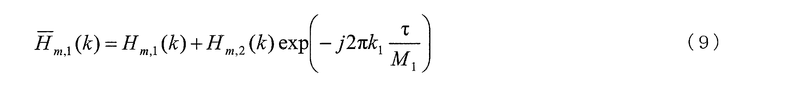
一方、CS方式を用いる既存ユーザの伝搬路情報については、本実施形態の伝搬路推定方法を用いて推定されたH ̄m,1(k)と第0ユーザとは空間多重されていない既存ユーザの参照信号の受信信号を用いて、あらためてCS方式を適用することにより、各送信アンテナの伝搬路情報Hm,1(k)およびHm,2(k)を推定することが出来る。
一方で、位相回転量τがある程度大きい場合には隣接する参照信号の周波数成分に与えられた位相差を無視することは出来ない。この場合は、隣接する3個の受信周波数成分を用いて伝搬路推定を行うことが出来る。このとき、受信信号は式(2)で表現することが可能であるが、R、 P、 HおよびNは次式で与えられる。
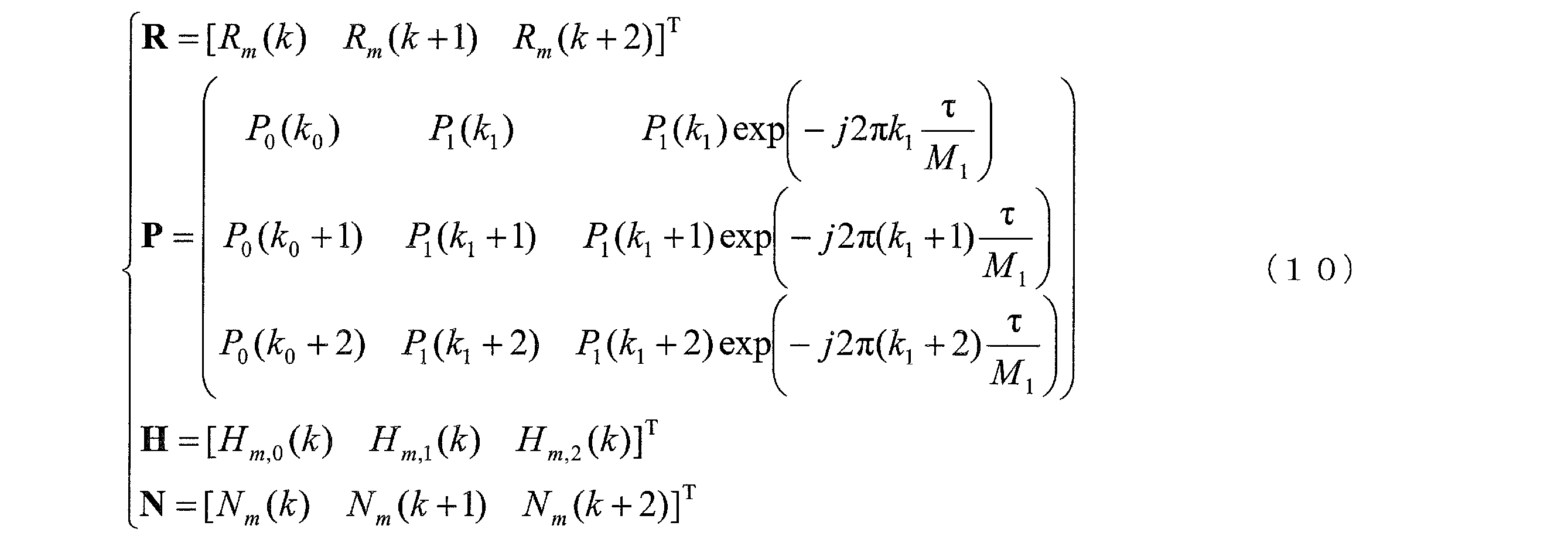
第1実施形態と同様に、参照信号系列によって構成させる行列Pを用いてMMSE規範のフィルタを求め受信信号Rに乗算することで、Hを推定することが出来るから、本発明の伝搬路推定方法を用いる第0ユーザの伝搬路情報Hm,0(k)はそのまま推定することができる。
そして、CS方式を用いる既存ユーザの伝搬路情報については、位相回転量τが小さい場合と同様に、本実施形態の伝搬路推定により推定されたHm,1(k)およびHm,2(k)と、空間多重されてない参照信号の受信信号を用いてあらためてCS方式を適用することで、伝送帯域全ての伝搬路情報を推定することが可能である。
CS方式を用いるユーザと本実施形態の伝搬路推定を用いるユーザが混在する場合の伝搬路推定方法について説明した。ここではユーザ数や各ユーザの送信アンテナ数に制限を与えて説明をしたが、ユーザ数が2より大きい場合や、伝搬路情報を推定することは可能である。
また、同一の帯域幅の2ユーザに対して、さらに別のユーザの信号スペクトルの一部が空間多重されても伝搬路情報を推定することが可能であることから、複数の送信アンテナを用いてシングルユーザMIMO伝送を行うユーザの信号スペクトルに対して、別のユーザの信号スペクトルの一部が空間多重されている場合においても伝搬路情報を推定可能であることを意味しているから、各ユーザの送信アンテナ数が複数であっても本実施形態により、信号スペクトルの一部が空間多重される上りリンクMU-MIMOを実現することが可能である。
また、第1実施形態でも述べたが、周波数マッピングにより各ユーザの伝送帯域幅や周波数が完全に一致している場合にはCS方式により伝搬路情報を推定しても良い。また、第1ユーザと第2ユーザの直交性を保ちつつ、第1の実施形態と同様に、第0ユーザに適用される伝搬路推定方法に応じて、参照信号に与える位相回転量を適切に変化させても良い。
これまで述べてきたように、本実施形態により、CS方式により既にユーザ間の直交性が保たれている信号スペクトルに対して、さらに新たなユーザの信号スペクトルの一部がMU-MIMOにより空間多重された場合でも、伝搬路推定を行うことが可能となる。例えばLTE-AのようにLTEとの後方互換性を維持しなければならないようなシステムに対しても信号スペクトルの一部が重畳するようなMU-MIMOを適用することが可能となり、周波数利用効率のより一層の向上に寄与できる。
[変形例]
以上、この発明の実施形態について図面を参照して詳述してきたが、具体的な構成はこの実施形態に限られるものではなく、この発明の要旨を逸脱しない範囲の設計等も特許請求の範囲に含まれる。
以上、この発明の実施形態について図面を参照して詳述してきたが、具体的な構成はこの実施形態に限られるものではなく、この発明の要旨を逸脱しない範囲の設計等も特許請求の範囲に含まれる。
また、本実施形態における送信装置及び受信装置で動作するプログラムは、本実施形態の機能を実現するように、CPU等を制御するプログラム(コンピュータを機能させるプログラム)である。そして、これら装置で取り扱われる情報は、その処理時に一時的にRAMに蓄積され、その後、各種ROMやHDDに格納され、必要に応じてCPUによって読み出し、修正・書き込みが行なわれる。プログラムを格納する記録媒体としては、半導体媒体(例えば、ROM、不揮発性メモリカード等)、光記録媒体(例えば、DVD、MO、MD、CD、BD等)、磁気記録媒体(例えば、磁気テープ、フレキシブルディスク等)等のいずれであってもよい。また、ロードしたプログラムを実行することにより、上述した実施形態の機能が実現されるだけでなく、そのプログラムの指示に基づき、オペレーティングシステムあるいは他のアプリケーションプログラム等と共同して処理することにより、実現される場合もある。
また市場に流通させる場合には、可搬型の記録媒体にプログラムを格納して流通させたり、インターネット等のネットワークを介して接続されたサーバコンピュータに転送したりすることができる。この場合、サーバコンピュータの記憶装置も本発明に含まれる。
また、上述した実施形態における送信装置及び受信装置の一部、または全部を典型的には集積回路であるLSIとして実現してもよい。送信装置及び受信装置の各機能ブロックは個別にプロセッサ化してもよいし、一部、または全部を集積してプロセッサ化してもよい。また、集積回路化の手法はLSIに限らず専用回路、または汎用プロセッサで実現しても良い。また、半導体技術の進歩によりLSIに代替する集積回路化の技術が出現した場合、当該技術による集積回路を用いることも可能である。
1 送信装置
102 チャネル符号化部
104 データ変調部
106 DFT部
108 参照信号多重部
110 周波数マッピング部
112 IFFT部
114 CP挿入部
116 無線送信部
118 無線受信部
120 制御情報取得部
122 参照信号系列生成部
2 受信装置
20 第1構成部
202 無線受信部
204 CP除去部
206 FFT部
208 参照信号分離部
210 推定方法切替部
212 伝搬路推定部
214 無線送信部
220 チャネル等化部
222 周波数デマッピング部
23 第2構成部
232 IDFT部
234 データ復調部
236 チャネル復号部
240 制御情報生成部
102 チャネル符号化部
104 データ変調部
106 DFT部
108 参照信号多重部
110 周波数マッピング部
112 IFFT部
114 CP挿入部
116 無線送信部
118 無線受信部
120 制御情報取得部
122 参照信号系列生成部
2 受信装置
20 第1構成部
202 無線受信部
204 CP除去部
206 FFT部
208 参照信号分離部
210 推定方法切替部
212 伝搬路推定部
214 無線送信部
220 チャネル等化部
222 周波数デマッピング部
23 第2構成部
232 IDFT部
234 データ復調部
236 チャネル復号部
240 制御情報生成部
Claims (7)
- 複数の送信装置と、複数の受信アンテナを備えた受信装置とを含む無線通信システムであって、
前記送信装置は、
前記送信装置と前記受信装置との間で既知の信号に、異なる時間シフトを加えた信号を参照信号として生成する参照信号生成部と、
データ信号と、前記参照信号とを多重化する参照信号多重部と、
前記参照信号多重部により多重化された信号を送信する送信部と、を有し、
前記受信装置は、
前記複数の送信装置から送信された信号を受信する受信部と、
前記受信部により受信された信号に多重化されている参照信号を分離する参照信号分離部と、
信号スペクトルの一部又は全体が共通の周波数を用いて送信された前記参照信号から伝搬路情報を推定する伝搬路推定部と、
前記伝搬路推定部により推定された伝搬路情報に基づいて、前記データ信号を復号する復号部と、
を備えることを特徴とする無線通信システム。 - 前記受信装置は前記伝搬路情報を推定するために複数の異なる伝搬路推定方法で伝搬路推定可能な伝搬路推定部を有し、前記複数の送信装置がそれぞれの信号の送信に用いる周波数の使用状況と、前記複数の伝搬路推定方法とが、関連付けられていることを特徴とする請求項1に記載の無線通信システム。
- 前記受信装置は、前記送信装置が信号の送信に用いる周波数の使用状況に応じて、前記伝搬路推定部の伝搬路推定方法を切り替える制御を行う推定方法切替部を更に有することを特徴とする請求項2に記載の無線通信システム。
- 前記推定方法切替部は、前記伝搬路推定方法の切り替えに応じて、前記送信装置において既知の信号に与える時間シフト量を変化させることを特徴とする請求項3に記載の無線通信システム。
- 無線通信システムには、送信装置として第一の送信装置と、第二の送信装置とが含まれており、
前記推定方法切替部は、第一の送信装置と、第二の送信装置とが用いる周波数が総て共通している場合と、第一の送信装置と第二の送信装置が用いる周波数が一部のみ共通している場合で、第一の送信装置と第二の送信装置とのそれぞれの伝搬路情報を推定するための推定方法を切り替える制御を行うことを特徴とする請求項3に記載の無線通信システム。 - 前記伝搬路情報を推定するための推定方法は、
前記第一の送信装置と前記第二の送信装置が用いる周波数が一部のみ共通している場合で、CS方式を利用し、前記周波数が一部のみ共通している場合には、空間フィルタ方式を利用することを特徴とする請求項5に記載の無線通信システム。 - 複数の送信装置と、複数の受信アンテナを備えた受信装置とを含む無線通信システムにおける受信装置であって、
データ信号と、前記送信装置と前記受信装置との間で既知の信号に異なる時間シフトを加えた信号である参照信号とが多重化された信号を受信する受信部と、
前記受信部により受信された信号に多重化されている参照信号を分離する参照信号分離部と、
前記参照信号から伝搬路情報を推定する伝搬路推定部と、
前記伝搬路推定部により推定された伝搬路情報に基づいて、前記データ信号を復号する復号部と、
を備えることを特徴とする受信装置。
Priority Applications (3)
| Application Number | Priority Date | Filing Date | Title |
|---|---|---|---|
| US13/636,054 US9225557B2 (en) | 2010-03-30 | 2011-03-29 | Radio communication system and receiving apparatus |
| CN201180015908.4A CN102823174B (zh) | 2010-03-30 | 2011-03-29 | 无线通信系统以及接收装置 |
| EP11762842.0A EP2555454A4 (en) | 2010-03-30 | 2011-03-29 | WIRELESS COMMUNICATION SYSTEM AND RECEIVER APPARATUS |
Applications Claiming Priority (2)
| Application Number | Priority Date | Filing Date | Title |
|---|---|---|---|
| JP2010078467A JP5501067B2 (ja) | 2010-03-30 | 2010-03-30 | 無線通信システム及び受信装置 |
| JP2010-078467 | 2010-03-30 |
Publications (1)
| Publication Number | Publication Date |
|---|---|
| WO2011122618A1 true WO2011122618A1 (ja) | 2011-10-06 |
Family
ID=44712313
Family Applications (1)
| Application Number | Title | Priority Date | Filing Date |
|---|---|---|---|
| PCT/JP2011/057797 WO2011122618A1 (ja) | 2010-03-30 | 2011-03-29 | 無線通信システム及び受信装置 |
Country Status (5)
| Country | Link |
|---|---|
| US (1) | US9225557B2 (ja) |
| EP (1) | EP2555454A4 (ja) |
| JP (1) | JP5501067B2 (ja) |
| CN (1) | CN102823174B (ja) |
| WO (1) | WO2011122618A1 (ja) |
Cited By (2)
| Publication number | Priority date | Publication date | Assignee | Title |
|---|---|---|---|---|
| CN104426820A (zh) * | 2013-08-22 | 2015-03-18 | 普天信息技术研究院有限公司 | 一种lte系统中信道估计的方法 |
| CN104426820B (zh) * | 2013-08-22 | 2018-06-01 | 普天信息技术研究院有限公司 | 一种lte系统中信道估计的方法 |
Families Citing this family (6)
| Publication number | Priority date | Publication date | Assignee | Title |
|---|---|---|---|---|
| JP6110650B2 (ja) * | 2012-12-12 | 2017-04-05 | 日本放送協会 | 回り込みキャンセラおよび中継装置 |
| EP3525533B1 (en) * | 2016-11-03 | 2021-01-06 | Huawei Technologies Co., Ltd. | Data transmission method, network device, and terminal device |
| CN108259150B (zh) * | 2016-12-29 | 2020-09-11 | 华为技术有限公司 | 一种信息传输方法及装置 |
| CN108632188B (zh) * | 2017-03-17 | 2021-04-20 | 华为技术有限公司 | 一种用于无线通信的方法、装置和系统 |
| KR102435428B1 (ko) | 2017-09-27 | 2022-08-24 | 삼성전자주식회사 | 무선 통신 시스템에서 패킷을 전송하기 위한 방법 및 장치 |
| US11071005B2 (en) * | 2019-06-27 | 2021-07-20 | Cisco Technology, Inc. | Congestion avoidance with adaptive QoS policy enforcement from SD-WAN controller in SD-WAN networks |
Citations (2)
| Publication number | Priority date | Publication date | Assignee | Title |
|---|---|---|---|---|
| JP2002344411A (ja) * | 2001-05-11 | 2002-11-29 | Sony Corp | Ofdm復調装置及び方法 |
| JP2009004926A (ja) * | 2007-06-19 | 2009-01-08 | Nec Corp | 移動通信システムにおけるリファレンス信号系列の割当方法および装置 |
Family Cites Families (7)
| Publication number | Priority date | Publication date | Assignee | Title |
|---|---|---|---|---|
| CN101112017B (zh) * | 2005-02-03 | 2011-06-01 | 富士通株式会社 | 无线通信系统及无线通信方法 |
| CN101189818A (zh) * | 2005-06-03 | 2008-05-28 | 松下电器产业株式会社 | 无线发送装置、无线接收装置及信号配置方法 |
| CN101467372A (zh) | 2006-06-07 | 2009-06-24 | 夏普株式会社 | 接收机和频率信息估计方法 |
| KR20080020934A (ko) * | 2006-09-01 | 2008-03-06 | 한국전자통신연구원 | 통신 시스템의 상향링크 신호 송신 방법, 송신 장치, 생성방법 및 생성 장치 |
| US8422581B2 (en) * | 2007-01-19 | 2013-04-16 | Panasonic Corporation | Multi-antenna transmission device, multi-antenna reception device, multi-antenna transmission method, multi-antenna reception method, terminal device, and base station device |
| WO2009041066A1 (ja) | 2007-09-28 | 2009-04-02 | Panasonic Corporation | 無線通信装置および系列長調整方法 |
| US20090168730A1 (en) * | 2007-10-29 | 2009-07-02 | Motorola, Inc. | Pilot Signal Allocation Method and Apparatus |
-
2010
- 2010-03-30 JP JP2010078467A patent/JP5501067B2/ja not_active Expired - Fee Related
-
2011
- 2011-03-29 WO PCT/JP2011/057797 patent/WO2011122618A1/ja active Application Filing
- 2011-03-29 US US13/636,054 patent/US9225557B2/en not_active Expired - Fee Related
- 2011-03-29 CN CN201180015908.4A patent/CN102823174B/zh not_active Expired - Fee Related
- 2011-03-29 EP EP11762842.0A patent/EP2555454A4/en not_active Withdrawn
Patent Citations (2)
| Publication number | Priority date | Publication date | Assignee | Title |
|---|---|---|---|---|
| JP2002344411A (ja) * | 2001-05-11 | 2002-11-29 | Sony Corp | Ofdm復調装置及び方法 |
| JP2009004926A (ja) * | 2007-06-19 | 2009-01-08 | Nec Corp | 移動通信システムにおけるリファレンス信号系列の割当方法および装置 |
Non-Patent Citations (4)
| Title |
|---|
| "Physical layer aspects for evolved Universal Terrestrial Radio Access (UTRA", 3GPP TR25.814, vol. 7.1.0, September 2006 (2006-09-01) |
| "UL RS enhancement for LTE-Advanced", 3GPP, R1-092801, NTT DOCOMO, June 2009 (2009-06-01) |
| NTT DOCOMO ET AL.: "UL RS Enhancement for LTE-Advanced", 3GPP TSG RAN WG1 MEETING #59 R1-094911, 9 November 2009 (2009-11-09), XP050389274 * |
| See also references of EP2555454A4 * |
Cited By (2)
| Publication number | Priority date | Publication date | Assignee | Title |
|---|---|---|---|---|
| CN104426820A (zh) * | 2013-08-22 | 2015-03-18 | 普天信息技术研究院有限公司 | 一种lte系统中信道估计的方法 |
| CN104426820B (zh) * | 2013-08-22 | 2018-06-01 | 普天信息技术研究院有限公司 | 一种lte系统中信道估计的方法 |
Also Published As
| Publication number | Publication date |
|---|---|
| EP2555454A4 (en) | 2016-06-29 |
| CN102823174B (zh) | 2015-06-03 |
| JP2011211587A (ja) | 2011-10-20 |
| EP2555454A1 (en) | 2013-02-06 |
| US9225557B2 (en) | 2015-12-29 |
| CN102823174A (zh) | 2012-12-12 |
| US20130016712A1 (en) | 2013-01-17 |
| JP5501067B2 (ja) | 2014-05-21 |
Similar Documents
| Publication | Publication Date | Title |
|---|---|---|
| US11546027B2 (en) | Base station apparatus, terminal apparatus, wireless communication system and integrated circuit | |
| US9008166B2 (en) | Filter calculating device, transmitting device, receiving device, processor, and filter calculating method | |
| US20130157667A1 (en) | Transmission device, reception device, relay device, communication system, transmission method, reception method, relay method, communication method, computer program, and semiconductor chip | |
| KR101567078B1 (ko) | 다중안테나를 이용한 데이터 전송장치 및 방법 | |
| JP5547988B2 (ja) | 通信システム、送信装置、受信装置、通信方法 | |
| US9124464B2 (en) | Methods and apparatus for channel estimation in MIMO-OFDM communication system | |
| US20150023279A1 (en) | Pre-coding device, wireless transmission device, wireless receiving device, wireless communication system, and integrated circuit | |
| JP5501067B2 (ja) | 無線通信システム及び受信装置 | |
| EP2352246B1 (en) | Multi-user mimo system, receiver apparatus and transmitter apparatus | |
| US20140369397A1 (en) | Communication device, communication method, communication program, processor, and communication system | |
| US20130343320A1 (en) | Terminal device, base station device, and wireless communication system | |
| WO2013183581A1 (ja) | 送信装置、受信装置、送信方法及び受信方法 | |
| US9071307B2 (en) | Wireless communication system, wireless communication apparatus, program and transmission method | |
| JP5704555B2 (ja) | 無線通信システム、及び受信装置 | |
| JP5538988B2 (ja) | 基地局装置、無線通信システム、基地局装置の送信方法、及び送信プログラム | |
| JP2010245641A (ja) | 無線システム、基地局装置、移動局装置、通信方法、プログラム | |
| JP2011155583A (ja) | 無線通信装置、無線通信方法、プログラム | |
| JP5441811B2 (ja) | 受信装置、基地局装置、無線通信システム、伝搬路推定方法、制御プログラムおよび集積回路 | |
| JP2010200077A (ja) | 移動通信システム、基地局装置、移動局装置および移動通信方法 | |
| WO2010084821A1 (ja) | 移動通信システム、基地局装置、移動局装置および移動通信方法 | |
| JP2011254355A (ja) | 無線通信システム、移動局装置および基地局装置 |
Legal Events
| Date | Code | Title | Description |
|---|---|---|---|
| WWE | Wipo information: entry into national phase |
Ref document number: 201180015908.4 Country of ref document: CN |
|
| 121 | Ep: the epo has been informed by wipo that ep was designated in this application |
Ref document number: 11762842 Country of ref document: EP Kind code of ref document: A1 |
|
| WWE | Wipo information: entry into national phase |
Ref document number: 2011762842 Country of ref document: EP |
|
| WWE | Wipo information: entry into national phase |
Ref document number: 13636054 Country of ref document: US |
|
| NENP | Non-entry into the national phase |
Ref country code: DE |