WO2011122574A1 - Medical device with slideable coating, and syringe - Google Patents
Medical device with slideable coating, and syringe Download PDFInfo
- Publication number
- WO2011122574A1 WO2011122574A1 PCT/JP2011/057679 JP2011057679W WO2011122574A1 WO 2011122574 A1 WO2011122574 A1 WO 2011122574A1 JP 2011057679 W JP2011057679 W JP 2011057679W WO 2011122574 A1 WO2011122574 A1 WO 2011122574A1
- Authority
- WO
- WIPO (PCT)
- Prior art keywords
- coating layer
- medical device
- syringe
- silicone
- component
- Prior art date
Links
Images


Classifications
-
- F—MECHANICAL ENGINEERING; LIGHTING; HEATING; WEAPONS; BLASTING
- F16—ENGINEERING ELEMENTS AND UNITS; GENERAL MEASURES FOR PRODUCING AND MAINTAINING EFFECTIVE FUNCTIONING OF MACHINES OR INSTALLATIONS; THERMAL INSULATION IN GENERAL
- F16J—PISTONS; CYLINDERS; SEALINGS
- F16J15/00—Sealings
- F16J15/16—Sealings between relatively-moving surfaces
- F16J15/32—Sealings between relatively-moving surfaces with elastic sealings, e.g. O-rings
- F16J15/3284—Sealings between relatively-moving surfaces with elastic sealings, e.g. O-rings characterised by their structure; Selection of materials
-
- A—HUMAN NECESSITIES
- A61—MEDICAL OR VETERINARY SCIENCE; HYGIENE
- A61L—METHODS OR APPARATUS FOR STERILISING MATERIALS OR OBJECTS IN GENERAL; DISINFECTION, STERILISATION OR DEODORISATION OF AIR; CHEMICAL ASPECTS OF BANDAGES, DRESSINGS, ABSORBENT PADS OR SURGICAL ARTICLES; MATERIALS FOR BANDAGES, DRESSINGS, ABSORBENT PADS OR SURGICAL ARTICLES
- A61L29/00—Materials for catheters, medical tubing, cannulae, or endoscopes or for coating catheters
- A61L29/08—Materials for coatings
- A61L29/085—Macromolecular materials
-
- A—HUMAN NECESSITIES
- A61—MEDICAL OR VETERINARY SCIENCE; HYGIENE
- A61M—DEVICES FOR INTRODUCING MEDIA INTO, OR ONTO, THE BODY; DEVICES FOR TRANSDUCING BODY MEDIA OR FOR TAKING MEDIA FROM THE BODY; DEVICES FOR PRODUCING OR ENDING SLEEP OR STUPOR
- A61M5/00—Devices for bringing media into the body in a subcutaneous, intra-vascular or intramuscular way; Accessories therefor, e.g. filling or cleaning devices, arm-rests
- A61M5/178—Syringes
- A61M5/31—Details
- A61M5/315—Pistons; Piston-rods; Guiding, blocking or restricting the movement of the rod or piston; Appliances on the rod for facilitating dosing ; Dosing mechanisms
- A61M5/31511—Piston or piston-rod constructions, e.g. connection of piston with piston-rod
- A61M5/31513—Piston constructions to improve sealing or sliding
-
- C—CHEMISTRY; METALLURGY
- C09—DYES; PAINTS; POLISHES; NATURAL RESINS; ADHESIVES; COMPOSITIONS NOT OTHERWISE PROVIDED FOR; APPLICATIONS OF MATERIALS NOT OTHERWISE PROVIDED FOR
- C09D—COATING COMPOSITIONS, e.g. PAINTS, VARNISHES OR LACQUERS; FILLING PASTES; CHEMICAL PAINT OR INK REMOVERS; INKS; CORRECTING FLUIDS; WOODSTAINS; PASTES OR SOLIDS FOR COLOURING OR PRINTING; USE OF MATERIALS THEREFOR
- C09D183/00—Coating compositions based on macromolecular compounds obtained by reactions forming in the main chain of the macromolecule a linkage containing silicon, with or without sulfur, nitrogen, oxygen, or carbon only; Coating compositions based on derivatives of such polymers
- C09D183/14—Coating compositions based on macromolecular compounds obtained by reactions forming in the main chain of the macromolecule a linkage containing silicon, with or without sulfur, nitrogen, oxygen, or carbon only; Coating compositions based on derivatives of such polymers in which at least two but not all the silicon atoms are connected by linkages other than oxygen atoms
-
- A—HUMAN NECESSITIES
- A61—MEDICAL OR VETERINARY SCIENCE; HYGIENE
- A61M—DEVICES FOR INTRODUCING MEDIA INTO, OR ONTO, THE BODY; DEVICES FOR TRANSDUCING BODY MEDIA OR FOR TAKING MEDIA FROM THE BODY; DEVICES FOR PRODUCING OR ENDING SLEEP OR STUPOR
- A61M2205/00—General characteristics of the apparatus
- A61M2205/02—General characteristics of the apparatus characterised by a particular materials
- A61M2205/0222—Materials for reducing friction
-
- A—HUMAN NECESSITIES
- A61—MEDICAL OR VETERINARY SCIENCE; HYGIENE
- A61M—DEVICES FOR INTRODUCING MEDIA INTO, OR ONTO, THE BODY; DEVICES FOR TRANSDUCING BODY MEDIA OR FOR TAKING MEDIA FROM THE BODY; DEVICES FOR PRODUCING OR ENDING SLEEP OR STUPOR
- A61M2205/00—General characteristics of the apparatus
- A61M2205/02—General characteristics of the apparatus characterised by a particular materials
- A61M2205/0238—General characteristics of the apparatus characterised by a particular materials the material being a coating or protective layer
-
- C—CHEMISTRY; METALLURGY
- C08—ORGANIC MACROMOLECULAR COMPOUNDS; THEIR PREPARATION OR CHEMICAL WORKING-UP; COMPOSITIONS BASED THEREON
- C08G—MACROMOLECULAR COMPOUNDS OBTAINED OTHERWISE THAN BY REACTIONS ONLY INVOLVING UNSATURATED CARBON-TO-CARBON BONDS
- C08G77/00—Macromolecular compounds obtained by reactions forming a linkage containing silicon with or without sulfur, nitrogen, oxygen or carbon in the main chain of the macromolecule
- C08G77/04—Polysiloxanes
- C08G77/12—Polysiloxanes containing silicon bound to hydrogen
-
- C—CHEMISTRY; METALLURGY
- C08—ORGANIC MACROMOLECULAR COMPOUNDS; THEIR PREPARATION OR CHEMICAL WORKING-UP; COMPOSITIONS BASED THEREON
- C08G—MACROMOLECULAR COMPOUNDS OBTAINED OTHERWISE THAN BY REACTIONS ONLY INVOLVING UNSATURATED CARBON-TO-CARBON BONDS
- C08G77/00—Macromolecular compounds obtained by reactions forming a linkage containing silicon with or without sulfur, nitrogen, oxygen or carbon in the main chain of the macromolecule
- C08G77/04—Polysiloxanes
- C08G77/20—Polysiloxanes containing silicon bound to unsaturated aliphatic groups
Definitions
- the present invention relates to a medical device having a slidable film having stable slidability, for example, a syringe gasket and a syringe provided with a gasket having stable slidability.
- the syringe is generally composed of an outer cylinder, a gasket that can slide in the syringe, and a plunger that moves the gasket.
- Many syringes improve the slidability of the gasket and provide high flow accuracy without causing any significant disturbance in the discharge of the chemical solution.For this reason, silicone oil or the like is used as a lubricant on the sliding part of the outer surface of the gasket or the inner surface of the syringe. It has been applied.
- Patent Document 1 Japanese Patent Laid-Open No. 62-32970
- Patent Document 2 Japanese Patent Laid-Open No. 2002-089717
- Patent Document 3 US Pat. No. 7,111,848, etc.
- Patent Document 4 Japanese Patent Laid-Open No. 2004-321614
- Patent Document 5 Japanese Patent Laid-Open No.
- Patent Document 7 WO2009-084646, US Publication No. 2010-0324501
- a composition containing a slidability imparting component, a flexibility imparting component and an adhesion component is devised, and the solid fine particles are obtained. Gaskets with a coating layer not included are also proposed.
- Patent Document 1 Japanese Patent Laid-Open No. 62-32470
- Patent Document 2 Japanese Patent Laid-Open No. 2002-089717
- Patent Document 3 US Pat. No. 7,111,848
- Patent Document 4 Japanese Patent Laid-Open No. 2004-321614
- Patent Document 5 Japanese Patent Laid-Open No. 2006-167110
- Patent Document 6 Japanese Patent Laid-Open No. 2008-2008
- 2007-0299402 has a liquid-tight property, and has a stable slidability without applying a lubricant to the sliding surface.
- the former there are various materials for forming the coating layer, and there are problems in manufacturing and cost.
- the latter case there is a problem that solid fine particles held in the coating layer are detached and insoluble fine particles are generated in the chemical solution.
- the gasket disclosed in Patent Document 7 (WO2009-084646, US Publication No. 2010-0324501) has been able to solve these problems.
- organotin compound as a catalyst is an essential constituent requirement. Yes.
- active studies have been conducted to regulate the use of organotin compounds depending on the region and application due to problems of toxicity and environmental impact.
- the present invention solves the above-mentioned problems, and can form a coating layer with a composition that does not require an organotin compound as a curing catalyst, and provides stable sliding properties without applying a lubricant to the sliding surface. It is intended to provide a medical device having a slidable coating film and a syringe provided with a gasket having stable slidability.
- a medical device that moves in contact with an inner surface of a medical member or an inner surface of a body cavity, the medical device comprising a slidable coating layer provided on a portion that contacts the medical member or body cavity, and the slidability
- the coating layer does not contain solid fine particles, and is made of a composition containing a silicone resin that is an addition reaction product of a silicone having a vinyl group and a silicone having a hydrogen group bonded to a silicon atom.
- Layer-owned medical device The syringe that achieves the above object is as follows.
- the medical device having a slidable coating layer that moves in contact with the inner surface of the medical member or the inner surface of the body of the present invention includes a slidable coating layer provided on a portion that contacts the medical member or the body cavity, and is slidable.
- the coating layer does not contain solid fine particles, and is made of a composition containing a silicone resin that is an addition reaction product of a silicone having a vinyl group and a silicone having a hydrogen group bonded to a silicon atom.
- the slidable coating layer of the medical device having the slidable coating layer of the present invention uses an addition reaction product of silicone having a vinyl group and silicone having a hydrogen group bonded to a silicon atom as a silicone resin.
- the organotin compound is not used as a catalyst during the curing reaction when forming the coating layer, even when the use of the organotin compound is regulated in the future, it can be stably supplied to the market. Furthermore, the slidable coating layer of the medical device having a slidable coating layer according to the present invention has good slidability at low-speed sliding compared to a coating layer containing fine particles, and a medical member (for example, There is no sticking between the outer cylinder for a syringe) and the medical device (for example, gasket) having a slidable coating layer, and a smooth initial motion is possible during use.
- a medical member for example, There is no sticking between the outer cylinder for a syringe
- the medical device for example, gasket
- FIG. 1 is a front view of a gasket which is an embodiment of the medical device having a slidable coating layer of the present invention.
- FIG. 2 is a cross-sectional view of the gasket shown in FIG.
- FIG. 3 is a plan view of the gasket shown in FIG.
- FIG. 4 is a bottom view of the gasket shown in FIG.
- FIG. 5 is a cross-sectional view of a prefilled syringe using the gasket shown in FIG.
- FIG. 6 is a cross-sectional view of a guide wire as an embodiment of the medical device having a slidable coating layer of the present invention.
- the slidable film-equipped medical device of the present invention will be described.
- the medical device 1 having a slidable coating film according to the present invention is a medical device that moves in contact with the inner surface of a medical member or the inner surface of a body cavity, and the slidable coating layer 3 provided on a portion in contact with the medical member or the body cavity.
- the slidable coating layer 3 does not contain solid fine particles, and is made of a composition containing a silicone resin that is an addition reaction product of a silicone having a vinyl group and a silicone having a hydrogen group bonded to a silicon atom. And it is preferable that the composition which forms the coating layer 3 does not contain a tin-type compound.
- the composition which forms the coating layer 3 contains a platinum group metal catalyst.
- the silicone resin of the composition forming the coating layer 3 is, as will be described later, a silicon bonded to a vinyl group of a silicone having a vinyl group and a hydrogen group of a silicone having a hydrogen group bonded to a silicon atom. And a silicone resin bonded by hydrosilylation.
- the slidable coating film-equipped medical device of the present invention will be described with reference to an example in which it is applied to a syringe gasket and a syringe.
- the gasket which is an Example of this invention is demonstrated.
- FIG. 1 is a front view of a gasket according to an embodiment of the present invention.
- FIG. 1 is a front view of a gasket according to an embodiment of the present invention.
- FIG. 2 is a cross-sectional view of the gasket shown in FIG.
- FIG. 3 is a plan view of the gasket shown in FIG.
- FIG. 4 is a bottom view of the gasket shown in FIG.
- FIG. 5 is a cross-sectional view of a prefilled syringe using the gasket shown in FIG.
- the medical device having a slidable coating film of this embodiment is a syringe gasket 1 which is stored in a liquid-tight and slidable manner inside a syringe outer cylinder 11 which is a medical member.
- a gasket 1 that is a medical device having a slidable film of the present invention is a gasket that is slidably in contact with an outer cylinder of a syringe, and includes a coating layer 3 provided on a portion that contacts the syringe.
- the coating layer 3 does not contain solid fine particles, and is formed of a composition containing a silicone resin that is an addition reaction product between a silicone having a vinyl group and a silicone having a hydrogen group bonded to a silicon atom.
- the coating layer since the coating layer is formed of the above-described composition, it has better slidability during low-speed sliding than the coating layer containing fine particles, and the syringe and gasket during storage.
- the gasket 1 of this embodiment is a syringe gasket 1 and is stored in a liquid-tight and slidable manner inside a syringe outer cylinder 11. Moreover, the gasket 1 is provided with the coating layer 3 provided in the part which contacts the outer cylinder 11, and the coating layer 3 contains the specific silicone type resin mentioned later.
- the gasket 1 includes a gasket body (in other words, a core portion) 2 and a coating layer 3 provided at least on the outer surface of the core portion 2 and in contact with the inner surface of the outer cylinder.
- the covering layer 3 may be provided on the entire outer surface of the core portion 2.
- the core portion 2 of the syringe gasket 1 has a main body portion 5 extending to substantially the same outer diameter and a tapered shape provided on the front end side of the main body portion 5 toward the front end side.
- the rear end side annular rib 7b provided on the rear end side surface of the main body 5 is provided.
- the plunger mounting portion 4 is a substantially cylindrical concave portion extending from the base end to the vicinity of the distal end portion inside the main body portion 5.
- a threaded portion 8 that can be threadedly engaged with a threaded portion formed in the portion is provided.
- the front end surface of the recess is formed substantially flat.
- the plunger mounting portion is not limited to the screwing portion, and may be an engaging portion that engages with the distal end portion of the plunger, or a combination of both.
- the attachment operation is performed by screwing, but the engagement state may be maintained by an engagement portion provided separately. Since the annular ribs 7 a and 7 b are made slightly larger than the inner diameter of the syringe outer cylinder 11, they are compressed and deformed in the outer cylinder 11. In the embodiment, two annular ribs are provided, but one or three or more ribs may be provided.
- the constituent material of the core part (gasket body) 2 is preferably an elastic material.
- the elastic material is not particularly limited.
- natural rubber isoprene rubber, butyl rubber, chloroprene rubber, nitrile-butadiene rubber, styrene-butadiene rubber, silicone rubber and other various rubber materials (particularly those vulcanized) Styrene elastomers, hydrogenated styrene elastomers, polyolefins such as polyethylene, polypropylene, polybutene, ⁇ -olefin copolymers, oils such as liquid paraffin, process oil, talc, cast, mica, etc. What mixed the powder inorganic substance is mentioned.
- polyvinyl chloride elastomers olefin elastomers, polyester elastomers, polyamide elastomers, polyurethane elastomers, and mixtures thereof can be used as constituent materials.
- a constituent material butyl rubber is particularly preferable from the viewpoint of having elastic characteristics and capable of high-pressure steam sterilization, and diene rubber and styrene elastomer from the viewpoint of enabling ⁇ -ray sterilization and electron beam sterilization. preferable.
- the coating layer 3 should just be provided in the cyclic
- the covering layer 3 may be formed on the entire outer surface of the core portion 2.
- the thickness of the coating layer 3 is preferably 1 to 30 ⁇ m, particularly 3 to 10 ⁇ m. If it is 1 ⁇ m or more, the required sliding performance is exhibited, and if it is 30 ⁇ m or less, the elasticity of the gasket is not affected.
- the coating layer 3 does not contain solid fine particles.
- the covering layer 3 is made of a resin made of a material having a lower friction coefficient than the elastic material constituting the core portion 2.
- the resin of the coating layer 3 is a silicone-based resin, and any of a solvent-based coating solution obtained by dissolving a silicone-based resin with an organic solvent and an aqueous coating solution emulsified and dispersed in water can be applied. Therefore, an aqueous coating solution that is easy to obtain suitability as a chemical solution storage container is preferable.
- the coating layer 3 is a silicone obtained by curing a silicone having a vinyl group and a silicone having a hydrogen group bonded to a silicon atom by addition reaction using platinum as a catalyst, and does not contain solid fine particles. ing. Moreover, it is preferable that it is a type of a thermosetting type silicone and a normal temperature curing type silicone, and especially thermosetting type silicone is preferable from points, such as workability
- the term “solid fine particles” as used herein refers to particles having a size that affects the roughness of the outer surface of the coating layer 3 when it is formed. Those having a particle size greater than 10%.
- the gasket 1 of the present invention has a stable slidability without applying a lubricant to the sliding surface, and maintains the sealing performance in the medicine storage space. Can do. And it is preferable that the initial sliding resistance value of the coating layer (in other words, the gasket having the coating layer) is not more than the maximum value of the dynamic sliding resistance value. In such a case, good initial sliding can be started and excessive initial movement does not occur.
- the method for forming the coating layer can be obtained by applying a coating liquid to a clean gasket surface and then curing.
- a conventionally known method such as dipping or spraying can be used.
- the coating solution spray coating
- spray coating it is preferable to perform the heat treatment on the coating target portion of the gasket at about 60 to 120 ° C. By doing so, the coating liquid is quickly fixed to the surface to be coated without water repellency.
- a curing method it may be left at room temperature, but heat curing is preferable.
- the method of heat-curing is not particularly limited as long as it is a method that does not alter or deform the gasket base material, and examples thereof include hot air drying and a drying furnace using infrared rays. Or it can also carry out by a conventionally well-known method, such as the method of using a vacuum dryer.
- the thickness of the coating layer to be formed may be about 1 to 30 ⁇ m, preferably 3 to 10 ⁇ m. In forming such a coating layer, it can be easily formed by appropriately controlling the concentration of the liquid mixture, the dipping method, or the spraying method.
- an aqueous coating liquid in which reactive silicone is easily emulsified and dispersed in water, which is easy to obtain suitability as a chemical liquid container as described above, is preferable.
- the specific silicone system of the coating layer 3 reacts so that the coating layer 3 is not peeled off from the core portion 2 or the coating layer 3 itself is not destroyed. It is characterized in that not only reactive silicone, which is a resin, but also a specific auxiliary agent for obtaining adhesion with the core part 2 and for increasing the strength of the coating layer are prescribed.
- the formulation of the aqueous coating liquid used in the present invention will be described.
- the active ingredient of the coating liquid is roughly divided into three types.
- Component 1 which is reactive silicone
- component 2 which is a reaction catalyst of component 1
- component 3 which is an auxiliary agent for preventing the coating layer 3 from being peeled off from the core portion 2 and being destroyed itself. Furthermore, an additive can be mix
- Component 1 Reactive silicone
- Component 2 Reaction catalyst and reaction inhibitor of Component 1
- Component 3 Auxiliary agent.
- Component 1 is a combination of two types (component 1a, component 1b).
- Component 1a is an emulsion of polysiloxane containing the main component of silicone of coating layer 3, and the polysiloxane is a polysiloxane having at least two vinyl groups in one molecule.
- There are two main methods for preparing this emulsion One is a method of preparing an emulsion of polydimethylsiloxane having at least two vinyl groups in one molecule by emulsion polymerization using cyclic siloxane (hereinafter referred to as “emulsion polymerization method”).
- the other is a method of preparing an emulsion by dispersing and emulsifying polysiloxane having at least two vinyl groups in one molecule in water (hereinafter referred to as “dispersion emulsification method”).
- an emulsion of polysiloxane having at least two vinyl groups in one molecule is prepared by dispersing and emulsifying cyclic siloxane, siloxane having vinyl group or silane, acid type emulsifier, and water. To do.
- Cyclic siloxanes include hexamethylcyclotrisiloxane, octamethylcyclotetrasiloxane, decamethylcyclopentasiloxane, dodecamethylcyclohexasiloxane, hexaethylcyclotrisiloxane, hexaphenylcyclotrisiloxane, octaphenylcyclotetrasiloxane, triphenyltrimethyl. Examples thereof include cyclotrisiloxane and (3,3,3-trifluoropropyl) methylcyclotrisiloxane.
- siloxane or silane having a vinyl group examples include 1,3,5-trivinyl-1,3,5-trimethylcyclotrisiloxane, 1,3,5,7-tetravinyl-1,3,5,7-tetramethyl.
- examples thereof include cyclotetrasiloxane, pentavinylpentamethylcyclopentasiloxane, vinyltrimethoxysilane, vinyltriethoxysilane, and tetrakis (vinyldimethylsiloxy) silane.
- the charging ratio (mol / mol) of the siloxane or silane having a vinyl group with respect to the cyclic siloxane is 0.01 to 0.3, more preferably 0.05 to 0.2.
- the acid type emulsifier known acid types of anionic surfactants can be used, and examples of the anionic surfactant include organic sulfonates, higher alcohol sulfates, higher alcohol ethoxylate sulfates, etc. Alkylbenzenesulfonic acid is preferred.
- a high-speed rotation type emulsifying apparatus such as a homomixer type, a comb-tooth type or an intermittent jet flow generation type can be used for rough emulsification, and a pressure homogenizer can be used for fine emulsification.
- Emulsion equipment and processing conditions are selected so that the coarse emulsion is a fine particle emulsion with an average particle size of around 1 ⁇ m, and the fine emulsion is further finely divided to provide a fine particle emulsion that does not exceed the average particle size of 500 nm. It is preferable to do this. Fine particles having an average particle size of more than several hundred nm after fine emulsification are liable to cause a creaming phenomenon due to coalescence of fine particles, and are not preferable in terms of emulsion stability.
- Emulsion polymerization is performed by heating a finely-emulsified product. Preferable heating conditions are 60 to 80 ° C. and 5 to 8 hours.
- the fine particles in the emulsion obtained by emulsion polymerization are mainly polysiloxanes having at least two vinyl groups in one molecule, the molecular weight is 60,000 to 400,000, and the vinyl group content is 0.5 to 10 wt%.
- the emulsion concentration of component 1a is preferably 30 to 60%.
- an emulsion is prepared by dispersing and emulsifying polysiloxane having at least two vinyl groups in one molecule, an emulsifier, and water.
- the polysiloxane having at least two vinyl groups in one molecule includes polydimethylsiloxane having vinyl groups at both ends, poly (diphenylsiloxane-dimethylsiloxane) having vinyl groups at both ends, and vinyl groups at both ends.
- Polyphenylmethylsiloxane poly (vinylphenylsiloxane-phenylmethylsiloxane) having vinylphenylmethyl groups at both ends, poly (trifluoropropylmethylsiloxane-dimethylsiloxane) having vinyl groups at both ends, vinyl groups at both ends
- the viscosity of the polysiloxane is 100 to 10,000 mPa ⁇ s, more preferably 500 to 5,000 mPa ⁇ s. Those having a viscosity exceeding 10,000 mPa ⁇ s are dispersed in water with a normal emulsifying device, and it is difficult to atomize to the target average particle size by emulsification.
- the molecular weight of the polysiloxane is 5,000 to 60,000, more preferably 10,000 to 50,000.
- the vinyl group content of the polysiloxane is 0.05 to 2 wt%.
- As the emulsifier a known anionic surfactant or nonionic surfactant can be used.
- Anionic surfactants include aliphatic monocarboxylates, polyoxyethylene alkyl ether carboxylates, N-acyl sarcosinates, N-acyl glutamates, dialkyl sulfosuccinates, alkane sulfonates, alpha olefin sulfonic acids Salt, linear alkylbenzenesulfonate, molecular chain alkylbenzenesulfonate, naphthalenesulfonate-formaldehyde condensate, alkylnaphthalenesulfonate, N-methyl-N-acyl taurine, alkyl sulfate, polyoxyethylene alkyl ether sulfate Salts, oil and fat sulfate esters, alkyl phosphates, polyoxyethylene alkyl ether sulfates, polyoxyethylene alkyl phenyl ether sulfates, and the like can be used.
- Nonionic surfactants include polyoxyethylene alkyl ethers, polyoxyalkylene derivatives, polyoxyethylene alkyl phenyl ethers, polyoxyethylene sorbitan fatty acid esters, fatty acid alkanolamides, glycerin fatty acid esters, sorbitan fatty acid esters, polyoxyethylene alkyls. Amines, alkyl alkanolamides and the like can be used. Of these, linear alkylbenzene sulfonic acid is preferred.
- a high-speed rotation type emulsifying apparatus such as a homomixer type, a comb-tooth type or an intermittent jet flow generation type can be used for rough emulsification, and a pressure homogenizer can be used for fine emulsification.
- Emulsion equipment and processing conditions are selected so that the coarse emulsion is a fine particle emulsion with an average particle size of around 1 ⁇ m, and the fine emulsion is further finely divided to provide a fine particle emulsion that does not exceed the average particle size of 500 nm. It is preferable to do this. Fine particles having an average particle size larger than several hundred nm after fine emulsification are liable to cause a creaming phenomenon and separation due to coalescence of the fine particles, and are not preferable in terms of emulsion stability.
- Component 1b is a polysiloxane emulsion contained in the silicone subcomponent of the coating layer 3 and reacts with the polysiloxane in the component 1a as the main component to serve as a crosslinking agent in the silicone of the coating layer 3. is there.
- the polysiloxane is a polysiloxane having hydrogen groups bonded to at least two silicon atoms in one molecule, and an emulsion is prepared by dispersing and emulsifying the polysiloxane, an emulsifier and water. The preparation method of an emulsion can be adjusted with the method similar to the dispersion emulsification method of the component 1a.
- polysiloxanes having hydrogen groups bonded to at least two silicon atoms in one molecule include polymethylhydrosiloxanes having trimethylsilyl groups at both ends, and poly (methylhydrosiloxane-dimethylsiloxane) having trimethylsilyl groups at both ends. , Polyethylhydrosiloxane having a trimethylsilyl group at both ends, poly (methylhydrosiloxane-octylmethylsiloxane) having a trimethylsilyl group at both ends, and the like. In some cases, both ends also serve as a chain extender.
- Polydimethylsiloxane having hydrogen groups bonded to silicon atoms, polyphenyl (dimethylhydro) siloxane having hydrogen groups bonded to silicon atoms at both ends, poly (methylhydro) having hydrogen groups bonded to silicon atoms at both ends (Siloxane-phenylmethylsiloxane) and the like can also be added.
- the viscosity of the component 1b polysiloxane is 2 to 1,000 mPa ⁇ s, more preferably 10 to 500 mPa ⁇ s.
- the molecular weight of the polysiloxane is 500 to 50,000, more preferably 1,000 to 20,000.
- the content of hydrogen groups bonded to silicon atoms is 100 mol% for polymethylhydrosiloxane having trimethylsilyl groups at both ends, poly (methylhydrosiloxane-dimethylsiloxane) having trimethylsilyl groups at both ends, and trimethylsilyl groups at both ends.
- the poly (methylhydrosiloxane-octylmethylsiloxane) has 3 to 50 mol%, and the polysiloxane having hydrogen groups at both ends has 0.01 to 0.5 wt%.
- the emulsion concentration of component 1b is preferably 30 to 60%.
- the blending amount of component 1b in the coating liquid is such that the amount of hydrogen groups of component 1b is 0.5 to 2.0, preferably 0.8 to 1.5, in terms of molar ratio relative to the amount of vinyl groups of component 1a.
- Component 2 one is a reaction catalyst between component 1a and component 1b, and the reaction catalyst is specifically a platinum group for promoting hydrosilylation of the vinyl group of component 1a and the hydrogen group of component 1b. It is a metal catalyst.
- platinum group metal catalyst platinum-based, palladium-based, and rhodium-based catalysts. Of these, platinum-based catalysts are preferred, and specific examples include chloroplatinic acid and alcohol-modified chloroplatinic acid. And a complex of chloroplatinic acid and ketones, a complex of platinum and olefin, and a complex of vinylsiloxane.
- the main component 1a and component 1b are polysiloxanes
- a complex of platinum and vinylsiloxane is preferable from the viewpoint of compatibility with them.
- platinum and vinylsiloxanecarbonylcyclovinylmethylsiloxane complex vinyl are used.
- examples thereof include a methyl cyclic siloxane solution, a platinum-divinyltetramethyldisiloxane complex-terminated vinylpolydimethylsiloxane solution, and a platinum-cyclovinylmethylsiloxane complex cyclic methylvinylsiloxane solution.
- the platinum concentration in these solutions is 1 to 3 wt%.
- the blending amount in the coating liquid is 1 to 1,000 ppm, preferably 5 to 500 ppm, more preferably 50 to 200 ppm, in terms of platinum with respect to the polysiloxane of component 1a.
- the form of component 2 is preferably an emulsion obtained by dispersing and emulsifying a complex of platinum and vinylsiloxane, an emulsifier, and water, and the preparation method can be the same as the dispersion emulsification method of component 1.
- As another reaction inhibitor between component 1a and component 1b specifically, hydrosilylation of the vinyl group of component 1a and the hydrogen group of component 1b during the storage period of the coating liquid during operation is moderate. It is an addition reaction inhibitor that suppresses the reaction to obtain stability.
- the blending amount in the coating solution is 0.1 to 10 wt%, more preferably 0.1 to 2 wt%, relative to the polysiloxane of
- Component 3 is an auxiliary agent for preventing the coating layer 3 from being peeled off from the core part 2 or destroying itself, and is an alkylalkoxysilane, phenylalkoxysilane, alkylphenoxysilane, aminoalkylalkoxy. Silane or glycidoxyalkylalkoxysilane is preferred.
- the alkylalkoxysilane has at least one alkyl group having 1 to 20 carbon atoms and at least one alkoxy group having 1 to 4 carbon atoms.
- the alkylphenoxysilane for example, methyltriphenoxysilane is suitable. Further, as the phenoxyalkoxysilane, phenyltrimethoxysilane, phenyltriethoxysilane, diphenyldimethoxysilane, diphenyldiethoxysilane and the like are preferable.
- the blending amount in the coating liquid is preferably 0.01 to 10 wt%, more preferably 0.1 to 5 wt% with respect to the polysiloxane of component 1a. If it is less than 0.1 wt%, it is difficult to obtain sufficient stability of the coating solution, and if it exceeds 10 wt%, the adhesion between the coating layer 3 and the core portion 2 becomes insufficient, such being undesirable.
- alkoxysilane having a ureido group (—NH—CO—NH 2 ) or an alkoxysilane having a ureylene group (—NH—CO—NH—).
- Alkoxysilanes having a ureido group (—NH—CO—NH 2 ) and alkoxysilanes having a ureylene group (—NH—CO—NH—) include ⁇ -ureidopropyltriethoxysilane and ⁇ -ureidopropyldiethoxymethylsilane.
- water-soluble is preferable from the viewpoint of dispersibility, and ⁇ -ureidopropyltriethoxysilane which is easily available from the point of commercial distribution is preferable.
- the reaction product of an alkoxysilane having an amino group and a dicarboxylic acid anhydride has a compounding ratio such that the amino group / carboxylic acid molar ratio is 0.5 to 2, preferably 0.8 to 1.2. It can be obtained by mixing an alkoxysilane having an amino group and a dicarboxylic acid anhydride and reacting in a solvent at a temperature of room temperature to 90 ° C. for several hours to several tens of hours.
- the solvent to be used include alcohols such as methanol, ethanol and isopropanol, and ketones such as acetone and methyl ethyl ketone, and it is preferably carried out under reflux of the solvent.
- alkoxysilane having an amino group examples include 3-aminopropyltriethoxysilane, 3- (2-aminoethyl) aminopropyltrimethoxysilane, 3- (2-aminoethyl) aminopropylmethyldimethoxysilane, and 3-aminopropyltrimethoxysilane.
- Methoxysilane, 3-phenylaminopropyltrimethoxysilane and the like are preferable.
- dicarboxylic acid anhydride examples include phthalic anhydride, succinic anhydride, maleic anhydride, glutaric anhydride, and the like.
- the blending amount in the coating liquid is preferably 1 to 10 wt%, more preferably 3 to 8 wt% with respect to the polysiloxane of component 1a. If it is less than 1 wt%, the adhesion between the coating layer 3 and the core part 2 will be insufficient, and if it exceeds 10 wt%, the flexibility and extensibility of the coating layer 3 will decrease and the adhesion to the core part 2 will occur. Is not preferable because it becomes insufficient.
- glycidoxyalkylalkoxysilane may be used.
- glycidoxyalkylalkoxysilane include 3-glycidoxypropyltrimethoxysilane, 3-glycidoxypropyltriethoxysilane, 3-glycidoxypropylmethyldiethoxysilane, 3-glycidoxypropylmethyldimethoxysilane, 2- (3,4-epoxycyclohexyl) ethyltrimethoxysilane and the like are preferred.
- the blending amount in the coating liquid is preferably 1 to 10 wt%, more preferably 3 to 8 wt% with respect to the polysiloxane of component 1a.
- the adhesion between the coating layer 3 and the core part 2 will be insufficient, and if it exceeds 10 wt%, the flexibility and extensibility of the coating layer 3 will decrease and the adhesion to the core part 2 will occur. Is not preferable because it becomes insufficient.
- surfactants and additives such as alcohol are used to uniformly emulsify, suspend and disperse the coating liquid at the stage of preparing the coating liquid by blending the above three active ingredients. May be.
- the surfactant is preferably an anionic (anionic) surfactant.
- Any anionic (anionic) surfactant may be used, including aliphatic monocarboxylates, polyoxyethylene alkyl ether carboxylates, N-acyl sarcosinates, N-acyl glutamates, and dialkyl sulfosuccinates.
- Acid salt alkane sulfonate, alpha olefin sulfonate, linear alkylbenzene sulfonate, molecular chain alkylbenzene sulfonate, naphthalenesulfonate-formaldehyde condensate, alkylnaphthalenesulfonate, N-methyl-N-acyl Taurine, alkyl sulfate, polyoxyethylene alkyl ether sulfate, fat and oil sulfate ester salt, alkyl phosphate, polyoxyethylene alkyl ether sulfate, polyoxyethylene alkyl phenyl ether sulfate and the like can be used.
- nonionic (nonionic) surfactant any nonionic (nonionic) surfactant may be used.
- Any nonionic (nonionic) surfactant may be used.
- Polyoxyethylene alkyl ether, polyoxyalkylene derivative, polyoxyethylene alkylphenyl ether, polyoxyethylene sorbitan fatty acid ester, fatty acid alkanolamide, glycerin fatty acid Esters, sorbitan fatty acid esters, polyoxyethylene alkylamines, alkylalkanolamides, and the like can be used.
- the syringe 10 of the present invention includes an outer cylinder 11, a gasket 1 slidably accommodated in the outer cylinder 11, and a plunger 17 attached to or attachable to the gasket 1.
- the syringe 10 includes a syringe outer cylinder 11 provided with an injection needle mounting portion 15 at the front end portion and a flange 16 facing the rear end portion, and an outer syringe portion.
- the syringe gasket 1 that can slide in an airtight and airtight manner on the inner surface 12 of the cylinder 11, the plunger 17 that can be attached to or attached to the syringe gasket 1, and the injection needle mounting portion 15 of the syringe outer cylinder 11 are sealed.
- the sealing member 18 comprises a sealing member 18 to be stopped, and a medicine storage portion 19 for storing a medicine 26 formed between the sealing member 18, the outer cylinder inner surface 12 and the syringe gasket 1.
- the injection needle attachment portion 15 may be attached with an injection needle instead of the sealing member 18.
- the sealing member may be of a type having a piercing part through which a double-ended needle can be directly inserted, or the medicine can be discharged only after the sealing member is removed. It may be a type.
- the gasket 1 includes the above-described stomach layer 3.
- the dynamic sliding resistance value at the time of low speed sliding (100 mm / min) of the gasket 1 in the outer cylinder 11 is 20 N or less.
- a low dynamic sliding resistance value can be obtained when the gasket 1 has the coating layer 3 described above.
- the dynamic sliding resistance value when the gasket 1 is slid at a low speed (100 mm / min) in the outer cylinder 11 is preferably 1N to 20N.
- the medical device is a prefilled syringe 25, and includes a syringe 10 and a drug 26 as shown in FIG.
- the outer cylinder 11 for a syringe is a cylindrical member in which an injection needle attachment portion 15 is provided at a front end portion and a flange portion 16 is provided at a rear end portion.
- the syringe outer cylinder 11 is made of a transparent or translucent material. Preferably, it is made of a material having low oxygen permeability and water vapor permeability. Further, the forming material is preferably a material having a glass transition point of 110 ° C. or higher or a melting point.
- various hard plastic materials for example, polypropylene, polyethylene, poly (4-methylpentene-1), polyolefin such as cyclic polyolefin, polyethylene terephthalate, polyethylene naphthalate, amorphous polyarate Polyester, polystyrene, polyamide, polycarbonate, polyvinyl chloride, acrylic resin, acrylonitrile-butadiene-styrene copolymer, amorphous polyetherimide, etc.
- polypropylene polyethylene
- polyolefin such as cyclic polyolefin
- polyethylene terephthalate polyethylene naphthalate
- amorphous polyarate Polyester polystyrene
- polyamide polycarbonate
- polyvinyl chloride acrylic resin
- acrylic resin acrylonitrile-butadiene-styrene copolymer
- amorphous polyetherimide etc.
- the plunger 17 includes a main body portion 20 extending in the axial direction having a cross-shaped cross section, and a plunger-side screwing provided at a distal end portion of the plunger 17 screwed with the plunger mounting portion 4.
- a plunger-side screwing provided at a distal end portion of the plunger 17 screwed with the plunger mounting portion 4.
- Part 21 a disc-shaped gasket support part provided between plunger-side threaded part 21 and main body part 20, pressing disk part 22 provided at the rear end of main body part 20, and main body part
- the disc-shaped rib provided in the middle of 20 is provided.
- the medicine 26 is accommodated in the inside of the syringe 10 of this embodiment.
- the drug 26 may be a liquid agent or a solid agent such as a powder or a freeze-drying agent.
- a drug solution such as a low-viscosity and high penetrating drug solution such as a drug solution containing a surfactant is used.
- the case where it is stored is preferable because it is a syringe that does not require silicone oil, but it can be stored properly even though it is difficult to achieve both the slidability and liquid tightness of the gasket.
- the coating layer 3 is provided on the syringe gasket 1 also on the portion that comes into contact with the stored medicine, even if the medicine liquid containing a poorly water-soluble medicine or the like has a high adsorptivity, the medicine adsorption is prevented. Since it is possible, it is preferable to use such a medicine.
- hard or semi-hard resin such as polyvinyl chloride, high density polyethylene, polypropylene, polystyrene, polyethylene terephthalate, polycarbonate, and acrylic resin.
- the syringe described above is an example of a medical tool that moves in contact with the inner surface of the medical member.
- a medical device is not limited to a syringe and may be any medical device as long as it can slide in the medical member.
- it may be a vial with a rubber stopper, an infusion bag, a blood collection tube, a reduced pressure blood collection tube, or the like.
- the medical device of the present invention is not limited to a syringe gasket, and may be any medical device such as an O-ring, a stopper, and a lid as long as it can slidably contact a medical member.
- the medical device of the present invention may be a rubber stopper for a vial, a lid for an infusion bag, or the like.
- the medical device of the present invention may be a medical device that moves in contact with the inner surface of the body cavity.
- the medical device that moves in contact with the inner surface of the body cavity include a catheter, a guide wire, and a vasodilator.
- the medical device of the present invention may be a medical device that moves in contact with the inner surface of the medical member and the inner surface of the body cavity.
- a catheter or guide that is inserted into a catheter for example, a guiding catheter
- a catheter for example, a guiding catheter
- the distal end portion is guided to a target site of the body cavity.
- wires and vasodilators There are wires and vasodilators.
- FIG. 6 is a cross-sectional view of one embodiment of the guide wire of the present invention.
- the guide wire 50 of this embodiment includes an inner core 52 and a slidable coating 53 that encapsulates the inner core 52.
- the slidable film 53 is made of silicone rubber and contains carbon nanotubes and silicone resin fine particles.
- the slidable film 3 has a roughened surface by containing fine particles.
- the inner core 52 of the guide wire 50 has a main body 52a and a tip 52b, and is integrally formed of an elastic metal.
- tip part 52b is formed so that it may become a diameter smaller than the front-end
- tip part 52b may be formed so that it may become a small diameter gradually toward a front-end
- the inner core 52 is preferably a super elastic metal, stainless steel, or the like.
- the TiNi alloy is particularly preferable.
- the outer diameter of the main body 52a of the inner core 52 is 0.10 to 1.00 mm, more preferably 0.15 to 0.40 mm, and the length is 1000 to 4000 mm, more preferably 1500 to 3000 mm.
- the buckling strength (yield stress during loading) is 30-100 kg / mm 2 (22 ° C.), more preferably 40-55 kg / mm 2
- the restoring stress (yield stress during unloading) is 20-80 kg / mm. 2 (22 ° C.), more preferably 30 to 35 kg / mm 2 .
- the outer diameter of the tip 52b of the inner core 52 is 0.03 to 0.15 mm, more preferably 0.05 to 0.10 mm, and the length is 10 to 300 mm, preferably 50 to 150 mm.
- the bending load is 0.1 to 10 g, preferably 0.3 to 6.0 g, and the restoring load is 0.1 to 10 g, preferably 0.3 to 6.0 g.
- the outer diameter of the tip of the inner core does not have to be the above-mentioned dimensions, and may be a part.
- the restoring stress of the main body and the tip does not need to have the same value, but it is preferable to devise so as to obtain appropriate physical properties at an appropriate wire diameter by changing it depending on the heat treatment conditions. That is, it is preferable to separate the heat treatment of the main body and the tip so that the restoring stress of the main body is large and the tip is flexible.
- the inner core 52 is not limited to a single line, but may be a plurality of parallel or twisted lines that exhibit the above-described function, that is, a stepwise or continuous change in physical properties.
- the high X-ray contrast unit 54 is a metal annular member having a high X-ray contrast property fixed to the tip of the inner core 52, specifically, a pipe-shaped member. Is formed. Gold, platinum, lead, silver, bismuth, tungsten and the like are preferable as the metal having high X-ray contrast properties, and gold is particularly preferable.
- the high X-ray contrast unit 54 is fixed by mechanical pressure bonding to the tip of the inner core 52 or soldering with a metal plated or vapor deposited on the tip of the inner core 52.
- the high X-ray contrast unit 54 has an outer diameter of 0.20 to 0.90 mm, preferably 0.25 to 0.40 mm, and an inner diameter of 0.04 to 0.16 mm, preferably 0.06 to 0.11 mm.
- the length is 1.00 to 10.00 mm, preferably 1.5 to 4.0 mm.
- the thin wire formed with the metal which has the above high X-ray contrast properties may be wound by the coil shape, for example.
- a wire having a wire diameter of 0.02 to 0.10 mm is preferably used.
- the length to be wound is 1.0 to 10.0 mm, preferably 1.5 to 4.0 mm from the tip of the inner core.
- the slidable coating 53 that covers the entire inner core 52 preferably has a substantially uniform outer diameter including the tip.
- the slidable coating 53 has a substantially uniform outer diameter so that a step or the like caused by the high X-ray contrast portion provided at the tip of the inner core 52 does not affect the outer surface shape of the guide wire 50.
- the same one as the slidable coating 3 described in the gasket of the above-described embodiment can be preferably used.
- the outer diameter of the slidable coating is 0.25 to 1.04 mm, preferably 0.30 to 0.64 mm, and the thickness of the inner core 52 on the main body 52a is preferably 0.25 to 1.04 mm. Is 0.30 to 0.64 mm.
- the tip of the guide wire 50 (the tip of the slidable coating 53) has a curved surface such as a hemisphere as shown in FIG. 6 in order to prevent damage to the blood vessel wall and to improve the operability of the guide wire 50. It is preferable that In the guide wire 50 of this embodiment, the entire inner core 52 is covered with the slidable coating 53, but the present invention is not limited to this.
- the slidable coating 53 may cover only a part of the inner core 52, for example, may cover only the tip of the inner core 52, or may cover only the main body of the inner core 52.
- Example 1 (Ingredient 1a) Weigh 125 g of octamethylcyclotetrasiloxane, 5 g of 1,3,5,7-tetravinyltetramethylcyclotetrasiloxane, 2.5 g of dodecylbenzenesulfonic acid and 22.5 g of water in a 300 mL tall beaker, and rotate at 6,000 rpm using a homomixer. The mixture was stirred at rpm for 10 minutes, and then 100 g of water was gradually added at a rotational speed of 2,000 rpm to effect rough emulsification.
- Example 1a Weigh 125 g of octamethylcyclotetrasiloxane, 5 g of 1,3,5,7-tetravinyltetramethylcyclotetrasiloxane, 2.5 g of dodecylbenzenesulfonic acid and 22.5 g of water in a 300 mL tall beaker, and rotate at
- fine emulsification was performed by passing twice using a pressure homogenizer under a pressure of 300 kg / cm 2 .
- the finely emulsified product was reacted at 70 ° C. for 6 hours, subsequently held at 15 ° C. for 12 hours for emulsion polymerization, and adjusted to pH 6.0 using a 10% aqueous sodium carbonate solution to complete the polymerization.
- the molecular weight of the polysiloxane obtained by polymerization was 330,000, and the vinyl group content was 4.5 wt%.
- the resulting preparation was used as component 1a.
- Component 1b Polymethylhydrogensiloxane with trimethylsilyl groups at both ends (hydrogen group content of 100 mol% bonded to silicon atom, viscosity 30 mPa ⁇ s, molecular weight 2,100) 75 g, dodecylbenzenesulfonic acid 1.5 g, water 73.5 g in a 300 mL tall beaker The sample was weighed and stirred for 10 minutes at 6,000 rpm using a homomixer to carry out rough emulsification. After degassing under reduced pressure, fine emulsification was performed by passing twice using a pressure homogenizer under a pressure of 300 kg / cm 2 . The resulting preparation was used as component 1b.
- Component 2 A polydimethylsiloxane solution (viscosity 50mPa ⁇ s, platinum content 3wt%) 75g, ethynylcyclohexanol 7.5g, dodecylbenzenesulfonic acid 1.5g, water 73.5g with a vinyl group at both ends of the platinum-divinyltetramethyldisiloxane complex The mixture was weighed into a 300 mL tall beaker and stirred for 10 minutes at a rotational speed of 6,000 rpm using a homomixer to perform rough emulsification. After degassing under reduced pressure, fine emulsification was performed by passing twice using a pressure homogenizer under a pressure of 300 kg / cm 2 .
- component 3 Methyltriethoxysilane, ⁇ -ureidopropyltriethoxysilane, and ⁇ -glycidoxypropyltrimethoxysilane were used as component 3.
- (Coating solution) 100g of component 1a, 3.4g of component 1b, 0.17g of component 2, 1g of methyltriethoxysilane of component 3, 1g of ⁇ -ureidopropyltriethoxysilane, 5g of ⁇ -glycidoxypropyltrimethoxysilane, water was mixed with 200 g to prepare a coating solution.
- Example 2 (Component 1a) The same as Example 1 except that 5 g of 1,3,5,7-tetravinyltetramethylcyclotetrasiloxane in Example 1 was changed to 10 g of 1,3,5,7-tetravinyltetramethylcyclotetrasiloxane. The resulting preparation was used as component 1a. The molecular weight of the polysiloxane obtained by polymerization was 310,000, and the vinyl group content was 5.4 wt%. (Component 1b) A preparation obtained as in Example 1 was used as component 1b. (Component 2) A preparation obtained as in Example 1 was used as component 2.
- Component 3 Phenyltriethoxysilane, ⁇ -ureidopropyltriethoxysilane, and ⁇ -glycidoxypropyltrimethoxysilane were used as component 3.
- (Coating solution) 100g of component 1a, 6.8g of component 1b, 0.34g of component 2, 1g of phenyltriethoxysilane of component 3, 5g of ⁇ -ureidopropyltriethoxysilane, 5g of ⁇ -glycidoxypropyltrimethoxysilane, water was mixed with 200 g to prepare a coating solution.
- Example 3 (Component 1a) The same as Example 1 except that 5 g of 1,3,5,7-tetravinyltetramethylcyclotetrasiloxane in Example 1 was changed to 1 g of 1,3,5,7-tetravinyltetramethylcyclotetrasiloxane. The resulting preparation was used as component 1a.
- the polysiloxane obtained by polymerization had a molecular weight of 350,000 and a vinyl group content of 3.8 wt%.
- Component 1b A preparation obtained as in Example 1 was used as component 1b.
- Component 2 A preparation obtained as in Example 1 was used as component 2.
- Component 3 Phenyltriethoxysilane, ⁇ -ureidopropyltriethoxysilane, and ⁇ -glycidoxypropyltrimethoxysilane were used as component 3.
- (Coating solution) 100g of component 1a, 0.68g of component 1b, 0.17g of component 2, 1g of phenyltriethoxysilane of component 3, 5g of ⁇ -ureidopropyltriethoxysilane, 5g of ⁇ -glycidoxypropyltrimethoxysilane, water 200 g was mixed to prepare a coating solution.
- Example 4 (Component 1a) A preparation obtained in the same manner as in Example 1 was designated as component 1a.
- the same preparation was carried out as in Example 1 except that the content was changed to a gensiloxane-dimethylsiloxane copolymer (content of hydrogen groups bonded to silicon atoms 30 mol%, viscosity 35 mPa ⁇ s, molecular weight 2,000). Used as.
- Component 2 A preparation obtained as in Example 1 was used as component 2.
- Component 3 Methyltriethoxysilane, ⁇ -ureidopropyltriethoxysilane, and ⁇ -glycidoxypropyltrimethoxysilane were used as component 3.
- (Coating solution) 100g of component 1a, 11.2g of component 1b, 0.17g of component 2, 1g of methyltriethoxysilane of component 3, 1g of ⁇ -ureidopropyltriethoxysilane, 5g of ⁇ -glycidoxypropyltrimethoxysilane, water 200 g was mixed to prepare a coating solution.
- Example 5 (Ingredient 1a) A preparation obtained as in Example 1 was used as component 1a.
- Component 1b A preparation obtained as in Example 1 was used as component 1b.
- Component 2 A preparation obtained as in Example 1 was used as component 2.
- Component 3) 140 g of ⁇ -aminopropyltriethoxysilane was added dropwise at room temperature to 62 g of maleic anhydride dissolved in 200 g of ethanol, and subsequently reacted at 80 ° C. under reflux of ethanol for 15 hours. The resulting reactants, methyltriethoxysilane and ⁇ -glycidoxypropyltrimethoxysilane were used as component 3.
- Example 6 (Component 1a) A preparation obtained as in Example 1 was used as component 1a.
- Component 1b A preparation obtained in the same way as in Example 4 was used as component 1b.
- Component 2 A preparation obtained as in Example 1 was used as component 2.
- Component 3 The reactants from component 3 of Example 5, phenyltriethoxysilane, ⁇ -glycidoxypropyltrimethoxysilane were used as component 3.
- Example 7 (Component 1a) Weigh 125 g of polydimethylsiloxane (vinyl group content 0.4 wt%, viscosity 500 mPa ⁇ s, molecular weight 17,200), 2.5 g of dodecylbenzenesulfonic acid, 122.5 g of water in a 300 mL tall beaker, The resulting mixture was stirred for 10 minutes at a rotational speed of 6,000 rpm for rough emulsification. After degassing under reduced pressure, fine emulsification was performed by passing twice using a pressure homogenizer under a pressure of 300 kg / cm 2 . The resulting preparation was used as component 1a.
- Component 1b A preparation obtained as in Example 1 was used as component 1b.
- Component 2 A preparation obtained as in Example 1 was used as component 2.
- Component 3 Methyltriethoxysilane, ⁇ -ureidopropyltriethoxysilane, and ⁇ -glycidoxypropyltrimethoxysilane were used as component 3.
- (Coating solution) 100g of component 1a, 1g of component 1b, 0.17g of component 2, 1g of methyltriethoxysilane of component 3, 5g of ⁇ -ureidopropyltriethoxysilane, 5g of ⁇ -glycidoxypropyltrimethoxysilane, 200g of water Were mixed to prepare a coating solution.
- Example 8 (Component 1a) In Example 7, polydimethylsiloxane having vinyl groups at both ends (vinyl group content 0.4 wt%, viscosity 500 mPa ⁇ s, molecular weight 17,200) and polydimethylsiloxane having both ends vinyl groups (vinyl group content 0.04) Except for changing to wt%, viscosity 10,000 mPa ⁇ s, molecular weight 62,700), the same procedure as in Example 7 was carried out, and the resulting preparation was used as component 1a. (Component 1b) A preparation obtained as in Example 1 was used as component 1b. (Component 2) A preparation obtained as in Example 1 was used as component 2.
- Component 3 The reactants from component 3 of Example 5, methyltriethoxysilane, ⁇ -glycidoxypropyltrimethoxysilane were used as component 3.
- (Coating solution) 100g of component 1a, 0.2g of component 1b, 0.34g of component 2, 1g of methyltriethoxysilane of component 3, 5g of reactant, 5g of ⁇ -glycidoxypropyltrimethoxysilane, and 200g of water mixed Thus, a coating solution was prepared.
- Comparative Example 1 (Component 1a) Weigh 125 g of octamethylcyclotetrasiloxane, 2.5 g of dodecylbenzenesulfonic acid, and 22.5 g of water in a 300 mL tall beaker, stir for 10 minutes at 6,000 rpm using a homomixer, and then 100 g of water at 2,000 rpm. Was gradually added to effect rough emulsification. After degassing under reduced pressure, fine emulsification was performed by passing twice using a pressure homogenizer under a pressure of 300 kg / cm 2 . The finely emulsified product was reacted at 70 ° C. for 6 hours, subsequently held at 15 ° C.
- component 1a The molecular weight of polysiloxane having silanol groups at both ends was 330,000.
- the resulting preparation was used as component 1a.
- component 1b In Comparative Example 1, component 1b was not used.
- Component 2 75 g of dioctyltin dilaurate, 12.5 g of polyoxyethylene styrenated phenyl ether cyethylene and 162.5 g of water were weighed in a 300 mL tall beaker and stirred for 10 minutes at a rotation speed of 6,000 rpm using a homomixer to carry out rough emulsification.
- Coating solution Mix 1g of component 1a, 1g of component 2, 1g of methyltriethoxysilane of component 3, 1g of ⁇ -ureidopropyltriethoxysilane, 5g of ⁇ -glycidoxypropyltrimethoxysilane, and 200g of water. A coating solution was prepared.
- the core part of the gasket for syringes of the shape shown in FIG. 1 and FIG. 2 was produced using butyl rubber.
- the core portion was formed by press molding a vulcanizable rubber composition in which an additive was added to butyl rubber.
- the shape of the obtained core portion is 20 mm in length, 30 mm in outer diameter at the front and rear end side annular rib portions, 10 mm in length between the front end side annular rib center and the rear end side annular rib center, and the front end side annular rib
- the outer diameter is 27 mm at the same outer diameter portion between the rear end side annular rib, the length (depth) of the concave portion for mounting the plunger having an internal thread portion is 10 mm, and the inner diameter is 18 mm at the front end side of the concave portion for mounting the plunger.
- the gasket core member produced as described above is heated at 90 ° C. for 30 minutes in a room temperature and normal pressure environment, the gasket core member is rotated (300 rpm) around its central axis, and the side surface side of the gasket rotating Further, after applying the coating liquids of Examples 1 to 8 and Comparative Example 1 by spraying, the gaskets of the present invention were produced by drying at 150 ° C. for 30 minutes. Then, in order to wash
- the average thickness of the coating layer formed on the surface of the core member was about 10 ⁇ m.
- Example 1 sliding resistance measurement test
- a syringe outer cylinder having a shape shown in FIG. 5 was produced by injection molding using polypropylene (manufactured by Nippon Polychem Co., Ltd.) as a forming material of the outer cylinder for syringe.
- the inner diameter of the cylindrical portion of the syringe outer cylinder was 29 mm, and the length was 121 mm.
- the plunger of the shape shown in FIG. 5 was produced by injection molding using polypropylene (manufactured by Nippon Polychem Co., Ltd.) as a plunger forming material.
- the syringe outer cylinder, the gaskets of Examples 1 to 8 and Comparative Example 1, and the plunger were assembled to produce a syringe.
- the sliding resistance value of each syringe was measured by an autograph (model name EZ-Test, company name Shimadzu Corporation). Specifically, the tip of the syringe and the rear end of the plunger are fixed to the measuring object fixing part of the autograph, and the initial sliding resistance value and the maximum sliding when the plunger is lowered by 60 mm at a speed of 100 mm / min.
- the dynamic resistance value (N) was measured, the results shown in Table 3 were obtained.
- the syringes using the gaskets of Examples 1 to 8 and Comparative Example 1 had the same initial sliding resistance value and maximum sliding resistance value. In addition, there is little difference between the initial sliding resistance value and the maximum sliding resistance value, and there is almost no risk of the chemical solution popping out beyond the set amount when the plunger is started to be discharged safely and accurately. it can. Good results of 10 N or less were obtained for both the initial sliding resistance value and the maximum sliding resistance value.
- the syringe outer cylinder, the gaskets of Examples 1 to 8 and Comparative Example 1, and the plunger were assembled to produce a syringe.
- 40 mL of purified water was poured into the syringe, and a sealing member was fitted on the tip of the syringe and sealed.
- autograph model name EZ-Test, Shimadzu Corporation stock
- the sliding resistance value was measured by the company). When the initial sliding resistance value and the maximum sliding resistance value (N) at a test speed of 20 to 500 mm / min were measured, the results shown in Table 2 were obtained.
- the syringes using the gaskets of Examples 1 to 8 have the same sliding resistance value as the gasket of Comparative Example 1 at a low test speed at 100 mm / min. Okay, it turns out that the slidability at a speed suitable for intravenous injection of the drug is better. Note that the number of samples in each test is 10, and the numerical values in the table are average values thereof.
- the outer cylinder for syringes of the shape shown in FIG. 5 was produced using glass (made by Shiotani Glass Co., Ltd.) as a forming material of the outer cylinder for syringes.
- the inner diameter of the cylindrical portion of the syringe outer cylinder was 23 mm, and the length was 76 mm.
- the plunger of the shape shown in FIG. 5 was produced by injection molding using polypropylene (manufactured by Nippon Polychem Co., Ltd.) as a plunger forming material.
- the syringe outer cylinder, the gaskets of Examples 1 to 8 and Comparative Example 1, and the plunger were assembled to produce a syringe.
- Example 2 Pressure test defined in the sterile syringe standard
- a syringe outer cylinder having a shape shown in FIG. 5 was produced by injection molding using polypropylene (manufactured by Nippon Polychem Co., Ltd.) as a forming material of the outer cylinder for syringe.
- the inner diameter of the cylindrical portion of the syringe outer cylinder was 29 mm, and the length was 121 mm.
- the plunger of the shape shown in FIG. 5 was produced by injection molding using polypropylene (manufactured by Nippon Polychem Co., Ltd.) as a plunger forming material.
- the syringe outer cylinder, the gaskets of Examples 1 to 8 and Comparative Example 1, and the plunger were assembled to produce a syringe.
- a sterilized plastic syringe barrel that can be used immediately as it is, and can be used for one-time use only.
- the sterilized syringe cylinder standard (December 11, 1998 from the Pharmaceutical Safety Bureau No. 1079)
- the test specified in the pressure test was performed. The results are shown in Table 1.
- the number of samples in the test was set to 5 and when all matched, it was set as “adapted”.
- a syringe outer cylinder having a shape shown in FIG. 5 was produced by injection molding using polypropylene (manufactured by Nippon Polychem Co., Ltd.) as a forming material of the outer cylinder for syringe.
- the inner diameter of the cylindrical portion of the syringe outer cylinder was 29 mm, and the length was 121 mm.
- the plunger of the shape shown in FIG. 5 was produced by injection molding using polypropylene (manufactured by Nippon Polychem Co., Ltd.) as a plunger forming material.
- Example 5 Insoluble particulate test
- a syringe outer cylinder having a shape shown in FIG. 5 was produced by injection molding using polypropylene (manufactured by Nippon Polychem Co., Ltd.) as a forming material of the outer cylinder for syringe.
- the inner diameter of the cylindrical portion of the syringe outer cylinder was 29 mm, and the length was 121 mm.
- the plunger of the shape shown in FIG. 5 was produced by injection molding using polypropylene (manufactured by Nippon Polychem Co., Ltd.) as a plunger forming material.
- Example 6 Flow rate accuracy evaluation test using a syringe pump
- a syringe pump (TE-331, manufactured by Terumo Corporation) was used to evaluate the flow rate accuracy of the syringe.
- a syringe outer cylinder having a shape shown in FIG. 5 was produced by injection molding using polypropylene (manufactured by Nippon Polychem Co., Ltd.) as a forming material of the outer cylinder for syringe.
- the inner diameter of the cylindrical portion of the syringe outer cylinder was 29 mm, and the length was 121 mm.
- the medical device having a slidable coating layer of the present invention is as follows. (1) A medical device that moves in contact with an inner surface of a medical member or an inner surface of a body cavity, the medical device including a slidable coating layer provided on a portion that contacts the medical member or the body cavity, The slidable coating layer does not contain solid fine particles, and is made of a composition containing a silicone resin that is an addition reaction product of a silicone having a vinyl group and a silicone having a hydrogen group bonded to a silicon atom. A medical device with a mobile coating layer.
- the silicone resin of the composition is hydrosilylated between the vinyl group of the silicone having the vinyl group and the silicon bonded to the hydrogen group of the silicone having a hydrogen group bonded to the silicon atom.
- the medical device having a slidable coating layer according to any one of (1) to (5), wherein the medical device is a silicone-based resin bonded together.
- the silicone according to any one of (1) to (6), wherein the silicone having a hydrogen group bonded to a silicon atom is a homopolymer or copolymer of polymethylhydrosiloxane having trimethylsilyl groups at both ends.
- a medical device with a mobile coating layer is a mobile coating layer.
- any of the above (1) to (8), wherein the silicone having a hydrogen group bonded to a silicon atom is a homopolymer or copolymer of polydimethylsiloxane having a hydrogen group bonded to a silicon atom at both ends.
- a medical device having a slidable coating layer as described in 1. The medical device having a slidable coating layer according to any one of (1) to (8), wherein the silicone having a vinyl group is siloxane or silane having a vinyl group.
- Layer-owned medical device (11) The above composition (1) to (10) containing a reaction product of an alkoxysilane having a ureido group or a ureylene group, or / and an alkoxysilane having an amino group and a carboxylic acid anhydride.
- the medical member is a syringe outer cylinder, the medical device is a syringe gasket slidably accommodated in the syringe outer cylinder, and the gasket is made of an elastic body.
- the medical device having a slidable coating layer according to any one of the above (1) to (14), comprising a slidable coating layer provided on a main body and at least a portion in contact with the outer cylinder for a syringe.
- the medical device having a slidable coating layer according to (16), wherein the medical member is a plastic syringe outer cylinder, and the medical device is a gasket for the plastic syringe outer cylinder.
- the syringe of the present invention is as follows. (18) An outer cylinder for syringe, a syringe gasket having the slidable coating layer-containing medical device of (16) or (17) and slidably accommodated in the outer cylinder, and attached to the gasket Syringe with attached or attachable plunger. (19) The syringe according to (18), wherein the syringe is filled with a chemical solution. (20) The syringe according to (18) or (19), wherein a dynamic sliding resistance value at the time of low-speed sliding of the gasket in the outer cylinder (100 mm / min) is 20 N or less. (21) The syringe according to any one of (18) to (20), wherein the outer cylinder is a plastic outer cylinder.
Abstract
The disclosed medical device with a slideable coating (1) moves in contact with the inner surface of a medical member or the inner surface of a body cavity, and is provided with a slideable coating (3) on the part that would be in contact with the medical member or the body cavity. The slideable coating (3) does not comprise microparticles and is configured from a composition that comprises a silicone resin that is a product of an addition reaction between a silicone that has a vinyl group and a silicone that has a hydrogen group bonded with a silicon atom.
Description
本発明は、安定した摺動性を有する摺動性被膜保有医療用具、例えば、シリンジ用ガスケット、および安定した摺動性を有するガスケットを備えたシリンジに関する。
The present invention relates to a medical device having a slidable film having stable slidability, for example, a syringe gasket and a syringe provided with a gasket having stable slidability.
従来から、薬剤取り違え、院内感染防止、廃棄性、病院業務の効率などの理由から薬液を予め充填したプレフィルドシリンジが使用されている。プレフィルドシリンジに使用されるシリンジに拘わらずシリンジは、一般に、外筒と、シリンジ内で摺動し得るガスケットと、このガスケットを移動操作するプランジャーとで構成されている。シリンジの多くは、ガスケットの摺動性を高め、薬液の吐出におおきな乱れが発生せずに高い流動精度を得るため、ガスケットの外面の摺動部若しくはシリンジの内面にシリコーンオイル等が潤滑剤として塗布されている。しかし、薬液によってはこのシリコーンオイル等の潤滑剤との相互作用が生じることが知られている。また、薬液を充填後長期間にわたって保管すると当該相互作用によって薬液が変質してしまうため、プレフィルド化が困難な薬剤もある。
特に薬液を充填した状態で長期間保管するプレフィルドシリンジにおいては、薬液の安定性を維持し続けられる、潤滑剤不要のものが望まれている。
そこで、上記の課題を解決するものとして、特許文献1(特開昭62-32970号公報)、特許文献2(特開2002-089717号公報)、特許文献3(米国特許7111848号公報)など、ガスケットの表面をガスケット本体材料より摩擦係数の低い材料であるフッ素系樹脂で被覆することにより、潤滑剤を不要としたプレフィルドシリンジが提案されている。
また、本出願人は、フッ素系樹脂、ケイ素系樹脂及びウレタン系樹脂により構成された被覆層を有するガスケットに関する特許文献4(特開2004-321614号公報)、摺動性付与成分と柔軟性付与成分とを含有する組成物により形成された被膜と、ガスケットに粗面表面を形成するため該被膜に保持された固体の微粒子とからなる被覆層を有するガスケットに関する特許文献5(特開2006-167110号公報)、特許文献6(特開2008-287号公報、米国公開2007-0299402)を提案している。さらには特許文献7(WO2009-084646号公報、米国公開2010-0324501)にて、摺動性付与成分、柔軟性付与成分及び密着性成分を含有する組成物を考案して、該固体の微粒子を含まない被覆層を有するガスケットも提案している。 Conventionally, prefilled syringes pre-filled with a chemical solution have been used for reasons such as drug mix-up, hospital infection prevention, disposability, and hospital work efficiency. Regardless of the syringe used for the prefilled syringe, the syringe is generally composed of an outer cylinder, a gasket that can slide in the syringe, and a plunger that moves the gasket. Many syringes improve the slidability of the gasket and provide high flow accuracy without causing any significant disturbance in the discharge of the chemical solution.For this reason, silicone oil or the like is used as a lubricant on the sliding part of the outer surface of the gasket or the inner surface of the syringe. It has been applied. However, it is known that an interaction with a lubricant such as silicone oil occurs depending on the chemical solution. Further, if the chemical solution is stored for a long time after being filled, the chemical solution is altered by the interaction, so that there are some drugs that are difficult to prefill.
In particular, in a prefilled syringe that is stored for a long time in a state of being filled with a chemical solution, a lubricant-free one that can maintain the stability of the chemical solution is desired.
In order to solve the above problems, Patent Document 1 (Japanese Patent Laid-Open No. 62-32970), Patent Document 2 (Japanese Patent Laid-Open No. 2002-089717), Patent Document 3 (US Pat. No. 7,111,848), etc. There has been proposed a prefilled syringe that does not require a lubricant by coating the surface of the gasket with a fluorine-based resin, which is a material having a lower coefficient of friction than the gasket body material.
In addition, the present applicant has disclosed Patent Document 4 (Japanese Patent Laid-Open No. 2004-321614) relating to a gasket having a coating layer made of a fluorine-based resin, a silicon-based resin, and a urethane-based resin. Patent Document 5 (Japanese Patent Laid-Open No. 2006-167110) relating to a gasket having a coating layer made of a composition containing a component and solid fine particles held on the coating to form a rough surface on the gasket Publication No. 2008-287, US Publication No. 2007-0299402). Furthermore, in Patent Document 7 (WO2009-084646, US Publication No. 2010-0324501), a composition containing a slidability imparting component, a flexibility imparting component and an adhesion component is devised, and the solid fine particles are obtained. Gaskets with a coating layer not included are also proposed.
上記特許文献1(特開昭62-32470号公報)、特許文献2(特開2002-089717号公報)、特許文献3(米国特許7111848号公報)に示されたガスケットは、使用条件によっては効果が期待できる。しかし、高い圧力をかけて薬液を吐出させたり、シリンジポンプ等を用いて薬液を極めて高い精度で長時間にわたって少量ずつ安定して吐出させる性能が求められるプレフィルドシリンジ製剤においては、シリンジに対して求められる基本性能である液密性と摺動性とがいまだトレードオフの関係にある。これらの性能を高い次元で両立させるとともに、更なる高機能を有するシリンジが必要とされている。
すなわちシリンジポンプを用いた薬液投与においては、目視では確認できない程の極低速条件下(例えば、直径約24mmのシリンジにおいて、1mL/時間で吐出させた場合の移動速度は約2mm/時間程度である)において薬液を吐出させた場合、脈動と呼ばれる不安定な吐出の状態が生じがちであり、薬液の正確な投与が妨げられるおそれがあった。
液密性と摺動性を両立するものとして提案された、特許文献4(特開2004-321614号公報)及び特許文献5(特開2006-167110号公報)、特許文献6(特開2008-287号公報、米国公開2007-0299402)に示されたガスケットは、液密性を備えかつ、摺動面に潤滑剤を付与することなく、安定した摺動性を有するものである。しかし、前者においては被覆層を形成する材料が多種にわたり製造上およびコスト上の問題がある。後者においてはさらに被覆層に保持された固体の微粒子が離脱してしまい薬液中に不溶性微粒子が発生してしまう問題があった。特許文献7(WO2009-084646号公報、米国公開2010-0324501)で示されたガスケットはこれら問題点を解決できたものではある。しかしながら、末端シラノール基を有する反応性シリコーンを触媒の有機スズ化合物を使用して縮合反応により硬化させて被覆層を形成させる製造原理であるため、触媒の有機スズ化合物が必須の構成要件となっている。近年、その毒性や環境への影響の問題により地域や用途に応じて有機スズ化合物の使用を規制する検討が活発に行われている。 The gaskets disclosed in Patent Document 1 (Japanese Patent Laid-Open No. 62-32470), Patent Document 2 (Japanese Patent Laid-Open No. 2002-089717), and Patent Document 3 (US Pat. No. 7,111,848) are effective depending on the use conditions. Can be expected. However, in prefilled syringe preparations that require high pressure to discharge chemicals or use syringe pumps to stably discharge chemicals in small amounts over a long period of time with extremely high accuracy, this is required for syringes. There is still a trade-off relationship between the liquid-tightness and the slidability, which are basic performances. There is a need for a syringe that achieves these performances at a high level and has higher functionality.
That is, in the case of drug solution administration using a syringe pump, the moving speed is about 2 mm / hour when discharged at 1 mL / hour in a syringe with a diameter of about 24 mm that cannot be confirmed visually. ), The unstable discharge state called pulsation tends to occur, and the accurate administration of the chemical solution may be hindered.
Patent Document 4 (Japanese Patent Laid-Open No. 2004-321614), Patent Document 5 (Japanese Patent Laid-Open No. 2006-167110), and Patent Document 6 (Japanese Patent Laid-Open No. 2008-2008), which have been proposed to achieve both liquid-tightness and slidability. No. 287, US Publication No. 2007-0299402) has a liquid-tight property, and has a stable slidability without applying a lubricant to the sliding surface. However, in the former, there are various materials for forming the coating layer, and there are problems in manufacturing and cost. In the latter case, there is a problem that solid fine particles held in the coating layer are detached and insoluble fine particles are generated in the chemical solution. The gasket disclosed in Patent Document 7 (WO2009-084646, US Publication No. 2010-0324501) has been able to solve these problems. However, since it is a manufacturing principle in which a reactive silicone having a terminal silanol group is cured by a condensation reaction using an organotin compound as a catalyst to form a coating layer, the organotin compound as a catalyst is an essential constituent requirement. Yes. In recent years, active studies have been conducted to regulate the use of organotin compounds depending on the region and application due to problems of toxicity and environmental impact.
本発明は、上記問題点を解決するものであり、硬化触媒の有機スズ化合物を必要としない組成物により被覆層を形成でき、摺動面に潤滑剤を付与することなく安定した摺動性を有する摺動性被膜保有医療用具および安定した摺動性を有するガスケットを備えたシリンジを提供するものである。
The present invention solves the above-mentioned problems, and can form a coating layer with a composition that does not require an organotin compound as a curing catalyst, and provides stable sliding properties without applying a lubricant to the sliding surface. It is intended to provide a medical device having a slidable coating film and a syringe provided with a gasket having stable slidability.
上記目的を達成するものは、下記のものである。
医療用部材内面もしくは体腔内面に接触して移動する医療用具であって、該医療用具は、前記医療用部材もしくは体腔と接触する部分に設けられた摺動性被覆層を備え、該摺動性被覆層は、固体微粒子を含まず、ビニル基を有するシリコーンとケイ素原子と結合した水素基を有するシリコーンとの付加反応物であるシリコーン系樹脂を含有する組成物からなるものである摺動性被覆層保有医療用具。
また、上記目的を達成するシリンジは、下記のものである。
シリンジ用外筒と、上記の摺動性被覆層保有医療用具でありかつ前記外筒内に摺動可能に収納されたシリンジ用ガスケットと、前記ガスケットに取り付けられた、あるいは取り付け可能なプランジャーとを有するシリンジ。 What achieves the above object is as follows.
A medical device that moves in contact with an inner surface of a medical member or an inner surface of a body cavity, the medical device comprising a slidable coating layer provided on a portion that contacts the medical member or body cavity, and the slidability The coating layer does not contain solid fine particles, and is made of a composition containing a silicone resin that is an addition reaction product of a silicone having a vinyl group and a silicone having a hydrogen group bonded to a silicon atom. Layer-owned medical device.
The syringe that achieves the above object is as follows.
An outer cylinder for a syringe, a gasket for a syringe that is a medical device having the above-described slidable coating layer and is slidably accommodated in the outer cylinder, and a plunger attached to or attachable to the gasket Syringe with
本発明の医療用部材内面もしくは体腔内面に接触して移動する摺動性被覆層保有医療用具は、医療用部材もしくは体腔と接触する部分に設けられた摺動性被覆層を備え、摺動性被覆層は、固体微粒子を含まず、ビニル基を有するシリコーンとケイ素原子と結合した水素基を有するシリコーンとの付加反応物であるシリコーン系樹脂を含有する組成物からなるものである。
特に、本発明の摺動性被覆層保有医療用具の摺動性被覆層は、ビニル基を有するシリコーンとケイ素原子と結合した水素基を有するシリコーンとの付加反応物をシリコーン系樹脂として用いていることから、被覆層形成時の硬化反応時に触媒として有機スズ化合物を使用しないものであるため、将来有機スズ化合物の使用が規制された場合においても、市場に安定して供給することができる。
さらに、本発明の摺動性被覆層保有医療用具の摺動性被覆層は、微粒子を含む被覆層に比べ、低速摺動時に良好な摺動性を有するとともに、保存時に医療用部材(例えば、シリンジ用外筒)と摺動性被覆層保有医療用具(例えば、ガスケット)間の貼り付きが生じることがなく、使用時に滑らかな初動が可能となる。 The medical device having a slidable coating layer that moves in contact with the inner surface of the medical member or the inner surface of the body of the present invention includes a slidable coating layer provided on a portion that contacts the medical member or the body cavity, and is slidable. The coating layer does not contain solid fine particles, and is made of a composition containing a silicone resin that is an addition reaction product of a silicone having a vinyl group and a silicone having a hydrogen group bonded to a silicon atom.
In particular, the slidable coating layer of the medical device having the slidable coating layer of the present invention uses an addition reaction product of silicone having a vinyl group and silicone having a hydrogen group bonded to a silicon atom as a silicone resin. Therefore, since the organotin compound is not used as a catalyst during the curing reaction when forming the coating layer, even when the use of the organotin compound is regulated in the future, it can be stably supplied to the market.
Furthermore, the slidable coating layer of the medical device having a slidable coating layer according to the present invention has good slidability at low-speed sliding compared to a coating layer containing fine particles, and a medical member (for example, There is no sticking between the outer cylinder for a syringe) and the medical device (for example, gasket) having a slidable coating layer, and a smooth initial motion is possible during use.
本発明の摺動性被膜保有医療用具について説明する。
本発明の摺動性被膜保有医療用具1は、医療用部材内面もしくは体腔内面に接触して移動する医療用具であり、医療用部材もしくは体腔と接触する部分に設けられた摺動性被覆層3を備える。摺動性被覆層3は、固体微粒子を含まず、ビニル基を有するシリコーンとケイ素原子と結合した水素基を有するシリコーンとの付加反応物であるシリコーン系樹脂を含有する組成物からなる。
そして、被覆層3を形成する組成物は、スズ系化合物を含有しないものであることが好ましい。また、被覆層3を形成する組成物は、白金族金属系触媒を含有するものであることが好ましい。そして、被覆層3を形成する組成物のシリコーン系樹脂は、後述するように、ビニル基を有するシリコーンのビニル基と、ケイ素原子と結合した水素基を有するシリコーンの水素基と結合しているケイ素とのヒドロシリル化により結合したシリコーン系樹脂である。
本発明の摺動性被膜保有医療用具をシリンジ用ガスケットおよびシリンジに応用した実施例を用いて説明する。
本発明の実施例であるガスケットについて説明する。
図1は、本発明の実施例であるガスケットの正面図である。図2は、図1に示すガスケットの断面図である。図3は、図1に示すガスケットの平面図である。図4は、図1に示すガスケットの底面図である。図5は、図1に示すガスケットを使用するプレフィルドシリンジの断面図である。
この実施例の摺動性被膜保有医療用具は、シリンジ用ガスケット1であり、医療用部材であるシリンジ用外筒11の内部に液密かつ摺動可能に収納されるものである。
本発明の摺動性被膜保有医療用具であるガスケット1は、シリンジの外筒内に摺動可能に接触するガスケットであって、シリンジと接触する部分に設けられた被覆層3を備えており、かつ、被覆層3は、固体微粒子を含まず、ビニル基を有するシリコーンとケイ素原子と結合した水素基を有するシリコーンとの付加反応物であるシリコーン系樹脂を含有する組成物により形成されている。
そして、この実施例のガスケットでは、被覆層は、上述した組成物により形成されているので、微粒子を含む被覆層に比べ、低速摺動時に良好な摺動性を有するとともに、保存時にシリンジとガスケットの貼り付きを起こすこともないため、使用時に滑らかな初動が可能となり、急激な注入が避けられ、一定速度での注入が可能となる。
また、血管確保の確認のために行われる事の多い吸引操作を行った場合でも、微粒子が入っている被覆層を有するガスケットでは、その微粒子の離脱の可能性が否定できないが、微粒子が無くなることにより薬液中に浮遊するリスクが皆無となるメリットを有している。
この実施例のガスケット1は、シリンジ用ガスケット1であり、シリンジ用外筒11の内部に液密かつ摺動可能に収納されるものである。また、ガスケット1は、外筒11と接触する部分に設けられた被覆層3を備えており、かつ、被覆層3は、後述する特定のシリコーン系樹脂を含有している。このガスケット1は、ガスケット本体(言い換えれば、コア部)2と、少なくともコア部2の外面であって外筒内面と接触する部分に設けられた被覆層3とを備えている。なお、コア部2の外面全体に被覆層3を設けてもよい。 The slidable film-equipped medical device of the present invention will be described.
Themedical device 1 having a slidable coating film according to the present invention is a medical device that moves in contact with the inner surface of a medical member or the inner surface of a body cavity, and the slidable coating layer 3 provided on a portion in contact with the medical member or the body cavity. Is provided. The slidable coating layer 3 does not contain solid fine particles, and is made of a composition containing a silicone resin that is an addition reaction product of a silicone having a vinyl group and a silicone having a hydrogen group bonded to a silicon atom.
And it is preferable that the composition which forms thecoating layer 3 does not contain a tin-type compound. Moreover, it is preferable that the composition which forms the coating layer 3 contains a platinum group metal catalyst. The silicone resin of the composition forming the coating layer 3 is, as will be described later, a silicon bonded to a vinyl group of a silicone having a vinyl group and a hydrogen group of a silicone having a hydrogen group bonded to a silicon atom. And a silicone resin bonded by hydrosilylation.
The slidable coating film-equipped medical device of the present invention will be described with reference to an example in which it is applied to a syringe gasket and a syringe.
The gasket which is an Example of this invention is demonstrated.
FIG. 1 is a front view of a gasket according to an embodiment of the present invention. FIG. 2 is a cross-sectional view of the gasket shown in FIG. FIG. 3 is a plan view of the gasket shown in FIG. FIG. 4 is a bottom view of the gasket shown in FIG. FIG. 5 is a cross-sectional view of a prefilled syringe using the gasket shown in FIG.
The medical device having a slidable coating film of this embodiment is asyringe gasket 1 which is stored in a liquid-tight and slidable manner inside a syringe outer cylinder 11 which is a medical member.
Agasket 1 that is a medical device having a slidable film of the present invention is a gasket that is slidably in contact with an outer cylinder of a syringe, and includes a coating layer 3 provided on a portion that contacts the syringe. The coating layer 3 does not contain solid fine particles, and is formed of a composition containing a silicone resin that is an addition reaction product between a silicone having a vinyl group and a silicone having a hydrogen group bonded to a silicon atom.
In the gasket of this example, since the coating layer is formed of the above-described composition, it has better slidability during low-speed sliding than the coating layer containing fine particles, and the syringe and gasket during storage. Since no sticking occurs, smooth initial movement is possible at the time of use, rapid injection is avoided, and injection at a constant speed is possible.
In addition, even when a suction operation that is often performed for confirming the blood vessel is performed, the possibility of detachment of the fine particles cannot be denied with the gasket having the coating layer containing the fine particles, but the fine particles are lost. This has the advantage that there is no risk of floating in the chemical solution.
Thegasket 1 of this embodiment is a syringe gasket 1 and is stored in a liquid-tight and slidable manner inside a syringe outer cylinder 11. Moreover, the gasket 1 is provided with the coating layer 3 provided in the part which contacts the outer cylinder 11, and the coating layer 3 contains the specific silicone type resin mentioned later. The gasket 1 includes a gasket body (in other words, a core portion) 2 and a coating layer 3 provided at least on the outer surface of the core portion 2 and in contact with the inner surface of the outer cylinder. The covering layer 3 may be provided on the entire outer surface of the core portion 2.
本発明の摺動性被膜保有医療用具1は、医療用部材内面もしくは体腔内面に接触して移動する医療用具であり、医療用部材もしくは体腔と接触する部分に設けられた摺動性被覆層3を備える。摺動性被覆層3は、固体微粒子を含まず、ビニル基を有するシリコーンとケイ素原子と結合した水素基を有するシリコーンとの付加反応物であるシリコーン系樹脂を含有する組成物からなる。
そして、被覆層3を形成する組成物は、スズ系化合物を含有しないものであることが好ましい。また、被覆層3を形成する組成物は、白金族金属系触媒を含有するものであることが好ましい。そして、被覆層3を形成する組成物のシリコーン系樹脂は、後述するように、ビニル基を有するシリコーンのビニル基と、ケイ素原子と結合した水素基を有するシリコーンの水素基と結合しているケイ素とのヒドロシリル化により結合したシリコーン系樹脂である。
本発明の摺動性被膜保有医療用具をシリンジ用ガスケットおよびシリンジに応用した実施例を用いて説明する。
本発明の実施例であるガスケットについて説明する。
図1は、本発明の実施例であるガスケットの正面図である。図2は、図1に示すガスケットの断面図である。図3は、図1に示すガスケットの平面図である。図4は、図1に示すガスケットの底面図である。図5は、図1に示すガスケットを使用するプレフィルドシリンジの断面図である。
この実施例の摺動性被膜保有医療用具は、シリンジ用ガスケット1であり、医療用部材であるシリンジ用外筒11の内部に液密かつ摺動可能に収納されるものである。
本発明の摺動性被膜保有医療用具であるガスケット1は、シリンジの外筒内に摺動可能に接触するガスケットであって、シリンジと接触する部分に設けられた被覆層3を備えており、かつ、被覆層3は、固体微粒子を含まず、ビニル基を有するシリコーンとケイ素原子と結合した水素基を有するシリコーンとの付加反応物であるシリコーン系樹脂を含有する組成物により形成されている。
そして、この実施例のガスケットでは、被覆層は、上述した組成物により形成されているので、微粒子を含む被覆層に比べ、低速摺動時に良好な摺動性を有するとともに、保存時にシリンジとガスケットの貼り付きを起こすこともないため、使用時に滑らかな初動が可能となり、急激な注入が避けられ、一定速度での注入が可能となる。
また、血管確保の確認のために行われる事の多い吸引操作を行った場合でも、微粒子が入っている被覆層を有するガスケットでは、その微粒子の離脱の可能性が否定できないが、微粒子が無くなることにより薬液中に浮遊するリスクが皆無となるメリットを有している。
この実施例のガスケット1は、シリンジ用ガスケット1であり、シリンジ用外筒11の内部に液密かつ摺動可能に収納されるものである。また、ガスケット1は、外筒11と接触する部分に設けられた被覆層3を備えており、かつ、被覆層3は、後述する特定のシリコーン系樹脂を含有している。このガスケット1は、ガスケット本体(言い換えれば、コア部)2と、少なくともコア部2の外面であって外筒内面と接触する部分に設けられた被覆層3とを備えている。なお、コア部2の外面全体に被覆層3を設けてもよい。 The slidable film-equipped medical device of the present invention will be described.
The
And it is preferable that the composition which forms the
The slidable coating film-equipped medical device of the present invention will be described with reference to an example in which it is applied to a syringe gasket and a syringe.
The gasket which is an Example of this invention is demonstrated.
FIG. 1 is a front view of a gasket according to an embodiment of the present invention. FIG. 2 is a cross-sectional view of the gasket shown in FIG. FIG. 3 is a plan view of the gasket shown in FIG. FIG. 4 is a bottom view of the gasket shown in FIG. FIG. 5 is a cross-sectional view of a prefilled syringe using the gasket shown in FIG.
The medical device having a slidable coating film of this embodiment is a
A
In the gasket of this example, since the coating layer is formed of the above-described composition, it has better slidability during low-speed sliding than the coating layer containing fine particles, and the syringe and gasket during storage. Since no sticking occurs, smooth initial movement is possible at the time of use, rapid injection is avoided, and injection at a constant speed is possible.
In addition, even when a suction operation that is often performed for confirming the blood vessel is performed, the possibility of detachment of the fine particles cannot be denied with the gasket having the coating layer containing the fine particles, but the fine particles are lost. This has the advantage that there is no risk of floating in the chemical solution.
The
シリンジ用ガスケット1のコア部2は、図1,図2,図5に示すように、ほぼ同一外径に延びる本体部5と、本体部5の先端側に設けられ先端側に向かってテーパー状に縮径するテーパー部6と、本体部5の基端から先端側に向かって内部に設けられたプランジャー取付部4と、本体部5の先端部側面に設けられた先端側環状リブ7aと、本体部5の後端部側面に設けられた後端側環状リブ7bを備えている。プランジャー取付部4は、図2,図4に示すように、本体部5の内部において基端から先端部付近まで延びる略円柱状の凹部となっており、凹部側面には、プランジャーの先端部に形成された螺合部と螺合可能な螺合部8が設けられている。凹部の先端面は、ほぼ平坦に形成されている。なお、プランジャー取付部は、螺合部に限定されず、プランジャーの先端部と係合する係合部であってもよいし、両者の組み合わせであってもよい。また取り付け操作は螺合によって行なわれるが係合状態は別途設けられた係合部によって維持されるものであってもよい。
環状リブ7a,7bは、シリンジ用外筒11の内径より若干大きく作製されているため、外筒11内で圧縮変形するものとなっている。また、実施例において、環状リブは、2つ設けられているが、1つあるいは3つ以上設けられていてもよい。 As shown in FIGS. 1, 2, and 5, thecore portion 2 of the syringe gasket 1 has a main body portion 5 extending to substantially the same outer diameter and a tapered shape provided on the front end side of the main body portion 5 toward the front end side. A taper portion 6 that is reduced in diameter, a plunger mounting portion 4 provided inside from the base end of the main body portion 5 toward the front end side, and a front end side annular rib 7a provided on a side surface of the front end portion of the main body portion 5. The rear end side annular rib 7b provided on the rear end side surface of the main body 5 is provided. As shown in FIGS. 2 and 4, the plunger mounting portion 4 is a substantially cylindrical concave portion extending from the base end to the vicinity of the distal end portion inside the main body portion 5. A threaded portion 8 that can be threadedly engaged with a threaded portion formed in the portion is provided. The front end surface of the recess is formed substantially flat. Note that the plunger mounting portion is not limited to the screwing portion, and may be an engaging portion that engages with the distal end portion of the plunger, or a combination of both. The attachment operation is performed by screwing, but the engagement state may be maintained by an engagement portion provided separately.
Since the annular ribs 7 a and 7 b are made slightly larger than the inner diameter of the syringe outer cylinder 11, they are compressed and deformed in the outer cylinder 11. In the embodiment, two annular ribs are provided, but one or three or more ribs may be provided.
環状リブ7a,7bは、シリンジ用外筒11の内径より若干大きく作製されているため、外筒11内で圧縮変形するものとなっている。また、実施例において、環状リブは、2つ設けられているが、1つあるいは3つ以上設けられていてもよい。 As shown in FIGS. 1, 2, and 5, the
Since the
コア部(ガスケット本体)2の構成材料としては、弾性材料であることが好ましい。弾性材料としては、特に限定されないが、例えば、天然ゴム、イソプレンゴム、ブチルゴム、クロロプレンゴム、ニトリル-ブタジエンゴム、スチレン-ブタジエンゴム、シリコーンゴム等の各種ゴム材料(特に、加硫処理したもの)や、スチレン系エラストマー、水添スチレン系エラストマー、及びこれらスチレン系エラストマーにポリエチレン、ポリプロピレン、ポリブテン、α-オレフィン共重合体等のポリオレフィンや、流動パラフィン、プロセスオイル等のオイルやタルク、キャスト、マイカなどの粉体無機物を混合したものが挙げられる。さらに、ポリ塩化ビニル系エラストマー、オレフィン系エラストマー、ポリエステル系エラストマー、ポリアミド系エラストマー、ポリウレタン系エラストマーや、それら混合物等が構成材料として使用できる。構成材料としては、特に、弾性特性を有し、高圧蒸気滅菌が可能などの観点からブチルゴムが好ましく、さらにγ線滅菌、電子線滅菌も可能となるなどの観点からジエン系ゴム、スチレン系エラストマーが好ましい。
The constituent material of the core part (gasket body) 2 is preferably an elastic material. The elastic material is not particularly limited. For example, natural rubber, isoprene rubber, butyl rubber, chloroprene rubber, nitrile-butadiene rubber, styrene-butadiene rubber, silicone rubber and other various rubber materials (particularly those vulcanized) Styrene elastomers, hydrogenated styrene elastomers, polyolefins such as polyethylene, polypropylene, polybutene, α-olefin copolymers, oils such as liquid paraffin, process oil, talc, cast, mica, etc. What mixed the powder inorganic substance is mentioned. Furthermore, polyvinyl chloride elastomers, olefin elastomers, polyester elastomers, polyamide elastomers, polyurethane elastomers, and mixtures thereof can be used as constituent materials. As a constituent material, butyl rubber is particularly preferable from the viewpoint of having elastic characteristics and capable of high-pressure steam sterilization, and diene rubber and styrene elastomer from the viewpoint of enabling γ-ray sterilization and electron beam sterilization. preferable.
被覆層3は、少なくとも環状リブ部分に設けられていればよい。具体的には、被覆層3は、先端側環状リブ7aと基端側環状リブ7b部分に設けられていればよい。なお、被覆層3は、コア部2の外面全体に形成されていてもよい。被覆層3の厚さは、1~30μm、特に、3~10μmであることが好ましい。1μm以上であれば、必要な摺動性能を発揮し、30μm以下であれば、ガスケットの弾性に影響を与えることがない。被覆層3は、固体微粒子を含まないものとなっている。
被覆層3は、コア部2を構成している前記弾性材料よりも、摩擦係数の低い材料で構成される樹脂で構成されている。被覆層3の樹脂はシリコーン系樹脂であり、シリコーン系樹脂を有機溶剤で溶解した溶剤系のコーティング液、および水に乳化、分散した水系コーティング液のいずれも適用できるが、溶剤系はガスケット材料への影響、残留溶剤の存在が懸念されるため、薬液収納容器としての適性が得られ易い水系コーティング液のものが好ましい。 Thecoating layer 3 should just be provided in the cyclic | annular rib part at least. Specifically, the coating layer 3 should just be provided in the front end side annular rib 7a and the base end side annular rib 7b part. The covering layer 3 may be formed on the entire outer surface of the core portion 2. The thickness of the coating layer 3 is preferably 1 to 30 μm, particularly 3 to 10 μm. If it is 1 μm or more, the required sliding performance is exhibited, and if it is 30 μm or less, the elasticity of the gasket is not affected. The coating layer 3 does not contain solid fine particles.
Thecovering layer 3 is made of a resin made of a material having a lower friction coefficient than the elastic material constituting the core portion 2. The resin of the coating layer 3 is a silicone-based resin, and any of a solvent-based coating solution obtained by dissolving a silicone-based resin with an organic solvent and an aqueous coating solution emulsified and dispersed in water can be applied. Therefore, an aqueous coating solution that is easy to obtain suitability as a chemical solution storage container is preferable.
被覆層3は、コア部2を構成している前記弾性材料よりも、摩擦係数の低い材料で構成される樹脂で構成されている。被覆層3の樹脂はシリコーン系樹脂であり、シリコーン系樹脂を有機溶剤で溶解した溶剤系のコーティング液、および水に乳化、分散した水系コーティング液のいずれも適用できるが、溶剤系はガスケット材料への影響、残留溶剤の存在が懸念されるため、薬液収納容器としての適性が得られ易い水系コーティング液のものが好ましい。 The
The
被覆層3は、ビニル基を有するシリコーンとケイ素原子と結合した水素基を有するシリコーンとを触媒の白金を使用して付加反応により硬化させて得られるシリコーンであり、固体微粒子を含まないものとなっている。また、熱硬化性型シリコーン、常温硬化型シリコーンのタイプであることが好ましく、特に作業性などの点より、熱硬化性型シリコーンが好ましい。
なお、本発明のガスケットに形成された被覆層3では、「固体微粒子」を含まないものとなっている。ここでいう「固体微粒子」とは、被覆層3を形成した場合にその外表面の粗度に影響を与える程度の大きさを有する粒子をいい、具体的には被覆層3の厚みに対して10%より大きい粒径を有するものをいう。
以上のように被覆層3を有することにより、本発明のガスケット1は、摺動面に潤滑剤を付与することなく安定した摺動性を有するとともに、薬剤収納空間内の密封性を維持することができる。そして、被覆層(言い換えれば、被膜層を有するガスケット)は、初期摺動抵抗値が動的摺動抵抗値の最高値以下であることが好ましい。このようなものであれば、良好な初期摺動が開始できかつ、過剰な初期移動を起こすこともない。 Thecoating layer 3 is a silicone obtained by curing a silicone having a vinyl group and a silicone having a hydrogen group bonded to a silicon atom by addition reaction using platinum as a catalyst, and does not contain solid fine particles. ing. Moreover, it is preferable that it is a type of a thermosetting type silicone and a normal temperature curing type silicone, and especially thermosetting type silicone is preferable from points, such as workability | operativity.
Note that thecoating layer 3 formed on the gasket of the present invention does not contain “solid fine particles”. The term “solid fine particles” as used herein refers to particles having a size that affects the roughness of the outer surface of the coating layer 3 when it is formed. Those having a particle size greater than 10%.
By having thecoating layer 3 as described above, the gasket 1 of the present invention has a stable slidability without applying a lubricant to the sliding surface, and maintains the sealing performance in the medicine storage space. Can do. And it is preferable that the initial sliding resistance value of the coating layer (in other words, the gasket having the coating layer) is not more than the maximum value of the dynamic sliding resistance value. In such a case, good initial sliding can be started and excessive initial movement does not occur.
なお、本発明のガスケットに形成された被覆層3では、「固体微粒子」を含まないものとなっている。ここでいう「固体微粒子」とは、被覆層3を形成した場合にその外表面の粗度に影響を与える程度の大きさを有する粒子をいい、具体的には被覆層3の厚みに対して10%より大きい粒径を有するものをいう。
以上のように被覆層3を有することにより、本発明のガスケット1は、摺動面に潤滑剤を付与することなく安定した摺動性を有するとともに、薬剤収納空間内の密封性を維持することができる。そして、被覆層(言い換えれば、被膜層を有するガスケット)は、初期摺動抵抗値が動的摺動抵抗値の最高値以下であることが好ましい。このようなものであれば、良好な初期摺動が開始できかつ、過剰な初期移動を起こすこともない。 The
Note that the
By having the
次に、被覆層3の形成方法について説明する。被膜層の形成方法は、コーティング液を清浄なガスケット表面に対して塗布させた後、硬化させることで得られる。このとき、ガスケット表面に塗布させる方法としては、浸漬法、噴霧法等、従来公知の方法で行うことができる。特に、被覆対象物を回転(具体的には、100~600rpm)させた状態にて、被覆液を噴霧塗布(スプレー塗布)することが好ましい。さらに、噴霧塗布を行う場合には、ガスケットの被覆対象部位を60~120℃程度に加熱処理した後に行うことが好ましい。このようにすることにより、被覆対象表面に対して、撥水することなく、速やかに被覆液が定着する。
硬化方法としては、常温放置でもよいが、加熱硬化が好ましい。加熱硬化させる方法としては、ガスケット基材を変質、あるいは変形させない方法であれば特に限定されるものではないが、熱風乾燥、赤外線を使用した乾燥炉などが挙げられる。あるいは減圧乾燥機を用いる方法など従来公知の方法で行うこともできる。形成される被覆層の厚さは、1~30μm程度で良く、好ましくは3~10μmである。このような被膜層を形成するにあたっては、混合液の濃度、あるいは浸漬手法、噴霧手法を適当に制御することで、容易に形成可能である。 Next, a method for forming thecoating layer 3 will be described. The method for forming the coating layer can be obtained by applying a coating liquid to a clean gasket surface and then curing. At this time, as a method of applying to the gasket surface, a conventionally known method such as dipping or spraying can be used. In particular, it is preferable to apply the coating solution (spray coating) in a state where the coating object is rotated (specifically, 100 to 600 rpm). Further, when spray coating is performed, it is preferable to perform the heat treatment on the coating target portion of the gasket at about 60 to 120 ° C. By doing so, the coating liquid is quickly fixed to the surface to be coated without water repellency.
As a curing method, it may be left at room temperature, but heat curing is preferable. The method of heat-curing is not particularly limited as long as it is a method that does not alter or deform the gasket base material, and examples thereof include hot air drying and a drying furnace using infrared rays. Or it can also carry out by a conventionally well-known method, such as the method of using a vacuum dryer. The thickness of the coating layer to be formed may be about 1 to 30 μm, preferably 3 to 10 μm. In forming such a coating layer, it can be easily formed by appropriately controlling the concentration of the liquid mixture, the dipping method, or the spraying method.
硬化方法としては、常温放置でもよいが、加熱硬化が好ましい。加熱硬化させる方法としては、ガスケット基材を変質、あるいは変形させない方法であれば特に限定されるものではないが、熱風乾燥、赤外線を使用した乾燥炉などが挙げられる。あるいは減圧乾燥機を用いる方法など従来公知の方法で行うこともできる。形成される被覆層の厚さは、1~30μm程度で良く、好ましくは3~10μmである。このような被膜層を形成するにあたっては、混合液の濃度、あるいは浸漬手法、噴霧手法を適当に制御することで、容易に形成可能である。 Next, a method for forming the
As a curing method, it may be left at room temperature, but heat curing is preferable. The method of heat-curing is not particularly limited as long as it is a method that does not alter or deform the gasket base material, and examples thereof include hot air drying and a drying furnace using infrared rays. Or it can also carry out by a conventionally well-known method, such as the method of using a vacuum dryer. The thickness of the coating layer to be formed may be about 1 to 30 μm, preferably 3 to 10 μm. In forming such a coating layer, it can be easily formed by appropriately controlling the concentration of the liquid mixture, the dipping method, or the spraying method.
コーティング液としては、上述の通り薬液収納容器としての適性が得られ易い、反応性シリコーンを水に乳化、分散した水系コーティング液のものが好ましい。但し、ガスケットを摺動させた時に、被覆層3がコア部2から剥がれてしまわないように、あるいは被覆層3自体が破壊してしまわないように、反応して被覆層3の特定のシリコーン系樹脂になる、反応性シリコーンだけでなく、コア部2との密着性を獲得するための、また被覆層の強度を高めるための特定の助剤が処方されている事が特徴である。本発明で使用する水性コーティング液の処方について説明する。コーティング液の有効成分は大きく分けて3種類の成分がある。反応性シリコーンである成分1、成分1の反応触媒である成分2、被覆層3がコア部2からの剥がれ、それ自体が破壊してしまわないための助剤である成分3である。さらに必要に応じて添加剤を配合することができる。成分1:反応性シリコーン、成分2:成分1の反応触媒及び反応抑制剤、成分3:助剤。
As the coating liquid, an aqueous coating liquid in which reactive silicone is easily emulsified and dispersed in water, which is easy to obtain suitability as a chemical liquid container as described above, is preferable. However, when the gasket is slid, the specific silicone system of the coating layer 3 reacts so that the coating layer 3 is not peeled off from the core portion 2 or the coating layer 3 itself is not destroyed. It is characterized in that not only reactive silicone, which is a resin, but also a specific auxiliary agent for obtaining adhesion with the core part 2 and for increasing the strength of the coating layer are prescribed. The formulation of the aqueous coating liquid used in the present invention will be described. The active ingredient of the coating liquid is roughly divided into three types. Component 1 which is reactive silicone, component 2 which is a reaction catalyst of component 1, and component 3 which is an auxiliary agent for preventing the coating layer 3 from being peeled off from the core portion 2 and being destroyed itself. Furthermore, an additive can be mix | blended as needed. Component 1: Reactive silicone, Component 2: Reaction catalyst and reaction inhibitor of Component 1, Component 3: Auxiliary agent.
以下に各成分を詳細に説明する。
成分1は2種類(成分1a、成分1b)の組み合わせである。成分1aは、被覆層3のシリコーンの主成分を含有するポリシロキサンのエマルジョンであり、そのポリシロキサンは一分子中に少なくとも2個のビニル基を有するポリシロキサンである。本エマルジョンの調製方法は大きく2つ挙げられる。一つは、環状シロキサンを使用した乳化重合により一分子中に少なくとも2個のビニル基を有するポリジメチルシロキサンのエマルジョンを調製する方法である(以下、「乳化重合法」と称す)。もう一つは、一分子中に少なくとも2個のビニル基を有するポリシロキサンを水へ分散、乳化させてエマルジョンを調製する方法である(以下、「分散乳化法」と称す)。 Each component will be described in detail below.
Component 1 is a combination of two types (component 1a, component 1b). Component 1a is an emulsion of polysiloxane containing the main component of silicone of coating layer 3, and the polysiloxane is a polysiloxane having at least two vinyl groups in one molecule. There are two main methods for preparing this emulsion. One is a method of preparing an emulsion of polydimethylsiloxane having at least two vinyl groups in one molecule by emulsion polymerization using cyclic siloxane (hereinafter referred to as “emulsion polymerization method”). The other is a method of preparing an emulsion by dispersing and emulsifying polysiloxane having at least two vinyl groups in one molecule in water (hereinafter referred to as “dispersion emulsification method”).
成分1は2種類(成分1a、成分1b)の組み合わせである。成分1aは、被覆層3のシリコーンの主成分を含有するポリシロキサンのエマルジョンであり、そのポリシロキサンは一分子中に少なくとも2個のビニル基を有するポリシロキサンである。本エマルジョンの調製方法は大きく2つ挙げられる。一つは、環状シロキサンを使用した乳化重合により一分子中に少なくとも2個のビニル基を有するポリジメチルシロキサンのエマルジョンを調製する方法である(以下、「乳化重合法」と称す)。もう一つは、一分子中に少なくとも2個のビニル基を有するポリシロキサンを水へ分散、乳化させてエマルジョンを調製する方法である(以下、「分散乳化法」と称す)。 Each component will be described in detail below.
乳化重合法では、環状シロキサン、ビニル基を有するシロキサンあるいはシラン、酸型乳化剤、水を分散、乳化させた後に重合を行い、一分子中に少なくとも2個のビニル基を有するポリシロキサンのエマルジョンを調製する。環状シロキサンとしては、ヘキサメチルシクロトリシロキサン、オクタメチルシクロテトラシロキサン、デカメチルシクロペンタシロキサン、ドデカメチルシクロヘキサシロキサン、ヘキサエチルシクロトリシロキサン、ヘキサフェニルシクロトリシロキサン、オクタフェニルシクロテトラシロキサン、トリフェニルトリメチルシクロトリシロキサン、(3,3,3-トリフルオロプロピル)メチルシクロトリシロキサン等が挙げられる。ビニル基を有するシロキサンあるいはシランとしては、1,3,5-トリビニル-1,3,5-トリメチルシクロトリシロキサン、1,3,5,7-テトラビニル-1,3,5,7-テトラメチルシクロテトラシロキサン、ペンタビニルペンタメチルシクロペンタシロキサン、ビニルトリメトキシシラン、ビニルトリエトキシシラン、テトラキス(ビニルジメチルシロキシ)シランなどが挙げられる。環状シロキサンに対するビニル基を有するシロキサンあるいはシランの仕込み比(mol/mol)は0.01~0.3であり、より好ましくは0.05~0.2である。酸型乳化剤は、公知のアニオン界面活性剤の酸型を使用でき、アニオン界面活性剤としては有機スルホン酸塩、高級アルコール硫酸エステル塩、高級アルコールエトキシレート硫酸エステル塩などが挙げられ、中でも直鎖アルキルベンゼンスルホン酸が好ましい。分散、乳化において用いられる乳化装置としては、粗乳化は高速回転型乳化装置、例えばホモミキサー型、櫛歯型、断続ジェット流発生型のもの、精乳化は圧力式ホモジナイザーを用いることができる。粗乳化では平均粒径1μm前後の微粒子のエマルジョンになるように、また精乳化ではさらに微粒化させて、目安として平均粒径500nmを超えない微粒子のエマルジョンになるように乳化装置、処理条件を選定するのが好ましい。精乳化後の平均粒径が数百nmより大きい微粒子は、微粒子の合一等によりクリーミング現象が起こりやすく、エマルジョンの安定性の点で好ましくない。乳化重合は、精乳化品を加熱して行う。好ましい加熱条件は60~80℃で5~8時間である。乳化重合により得られたエマルジョン中の微粒子は、主として一分子中に少なくとも2個のビニル基を有するポリシロキサンであり、その分子量は60,000~400,000、ビニル基の含有量は0.5~10wt%である。成分1aのエマルジョン濃度は30~60%が好適である。
In the emulsion polymerization method, an emulsion of polysiloxane having at least two vinyl groups in one molecule is prepared by dispersing and emulsifying cyclic siloxane, siloxane having vinyl group or silane, acid type emulsifier, and water. To do. Cyclic siloxanes include hexamethylcyclotrisiloxane, octamethylcyclotetrasiloxane, decamethylcyclopentasiloxane, dodecamethylcyclohexasiloxane, hexaethylcyclotrisiloxane, hexaphenylcyclotrisiloxane, octaphenylcyclotetrasiloxane, triphenyltrimethyl. Examples thereof include cyclotrisiloxane and (3,3,3-trifluoropropyl) methylcyclotrisiloxane. Examples of the siloxane or silane having a vinyl group include 1,3,5-trivinyl-1,3,5-trimethylcyclotrisiloxane, 1,3,5,7-tetravinyl-1,3,5,7-tetramethyl. Examples thereof include cyclotetrasiloxane, pentavinylpentamethylcyclopentasiloxane, vinyltrimethoxysilane, vinyltriethoxysilane, and tetrakis (vinyldimethylsiloxy) silane. The charging ratio (mol / mol) of the siloxane or silane having a vinyl group with respect to the cyclic siloxane is 0.01 to 0.3, more preferably 0.05 to 0.2. As the acid type emulsifier, known acid types of anionic surfactants can be used, and examples of the anionic surfactant include organic sulfonates, higher alcohol sulfates, higher alcohol ethoxylate sulfates, etc. Alkylbenzenesulfonic acid is preferred. As an emulsifying apparatus used for dispersion and emulsification, a high-speed rotation type emulsifying apparatus such as a homomixer type, a comb-tooth type or an intermittent jet flow generation type can be used for rough emulsification, and a pressure homogenizer can be used for fine emulsification. Emulsion equipment and processing conditions are selected so that the coarse emulsion is a fine particle emulsion with an average particle size of around 1 μm, and the fine emulsion is further finely divided to provide a fine particle emulsion that does not exceed the average particle size of 500 nm. It is preferable to do this. Fine particles having an average particle size of more than several hundred nm after fine emulsification are liable to cause a creaming phenomenon due to coalescence of fine particles, and are not preferable in terms of emulsion stability. Emulsion polymerization is performed by heating a finely-emulsified product. Preferable heating conditions are 60 to 80 ° C. and 5 to 8 hours. The fine particles in the emulsion obtained by emulsion polymerization are mainly polysiloxanes having at least two vinyl groups in one molecule, the molecular weight is 60,000 to 400,000, and the vinyl group content is 0.5 to 10 wt%. The emulsion concentration of component 1a is preferably 30 to 60%.
次に、分散乳化法では、一分子中に少なくとも2個のビニル基を有するポリシロキサン、乳化剤、水を分散、乳化させてエマルジョンを調製する。一分子中に少なくとも2個のビニル基を有するポリシロキサンとしては、両末端にビニル基を有するポリジメチルシロキサン、両末端にビニル基を有するポリ(ジフェニルシロキサン-ジメチルシロキサン)、両末端にビニル基を有するポリフェニルメチルシロキサン、両末端にビニルフェニルメチル基を有するポリ(ビニルフェニルシロキサン-フェニルメチルシロキサン)、両末端にビニル基を有するポリ(トリフルオロプロピルメチルシロキサン-ジメチルシロキサン)、両末端にビニル基を有するポリ(ジエチルシロキサン-ジメチルシロキサン)、両末端がトリメチルシリル基であるポリビニルメチルシロキサン、両末端がトリメチルシリル基であるポリ(ビニルメチルシロキサン-ジメチルシロキサン)、ポリビニルメトキシシロキサン、ポリビニルエトキシシロキサン、ポリ(ビニルエトキシシロキサン-プロピルエトキシシロキサン)などが挙げられる。該ポリシロキサンの粘度は100~10,000mPa・s、より好ましくは500~5,000mPa・sである。粘度が10,000mPa・sを越えるものは、通常の乳化装置で水中へ分散、乳化では目的の平均粒径までの微粒化が困難である。該ポリシロキサンの分子量は5,000~60,000、より好ましくは10,000~50,000である。該ポリシロキサンのビニル基の含有量は0.05~2wt%である。乳化剤は公知のアニオン界面活性剤、ノニオン界面活性剤を使用できる。アニオン界面活性剤としては、脂肪族モノカルボン酸塩、ポリオキシエチレンアルキルエーテルカルボン酸塩、N-アシルサルコシン酸塩、N-アシルグルタミン酸塩、ジアルキルスルホコハク酸塩、アルカンスルホン酸塩、アルファオレフィンスルホン酸塩、直鎖アルキルベンゼンスルホン酸塩、分子鎖アルキルベンゼンスルホン酸塩、ナフタレンスルホン酸塩-ホルムアルデヒド縮合物、アルキルナフタレンスルホン酸塩、N-メチル-N-アシルタウリン、アルキル硫酸塩、ポリオキシエチレンアルキルエーテル硫酸塩、油脂硫酸エステル塩、アルキルリン酸塩、ポリオキシエチレンアルキルエーテル硫酸塩、ポリオキシエチレンアルキルフェニルエーテル硫酸塩などが使用できる。また、ノニオン界面活性剤としては、ポリオキシエチレンアルキルエーテル、ポリオキシアルキレン誘導体、ポリオキシエチレンアルキルフェニルエーテル、ポリオキシエチレンソルビタン脂肪酸エステル、脂肪酸アルカノールアミド、グリセリン脂肪酸エステル、ソルビタン脂肪酸エステル、ポリオキシエチレンアルキルアミン、アルキルアルカノールアミドなどが使用できる。中でも直鎖アルキルベンゼンスルホン酸が好ましい。分散、乳化において用いられる乳化装置としては、粗乳化は高速回転型乳化装置、例えばホモミキサー型、櫛歯型、断続ジェット流発生型のもの、精乳化は圧力式ホモジナイザーを用いることができる。粗乳化では平均粒径1μm前後の微粒子のエマルジョンになるように、また精乳化ではさらに微粒化させて、目安として平均粒径500nmを超えない微粒子のエマルジョンになるように乳化装置、処理条件を選定するのが好ましい。精乳化後の平均粒径が数百nmより大きい微粒子は、微粒子の合一等によりクリーミング現象、分離が起こりやすく、エマルジョンの安定性の点で好ましくない。
Next, in the dispersion emulsification method, an emulsion is prepared by dispersing and emulsifying polysiloxane having at least two vinyl groups in one molecule, an emulsifier, and water. The polysiloxane having at least two vinyl groups in one molecule includes polydimethylsiloxane having vinyl groups at both ends, poly (diphenylsiloxane-dimethylsiloxane) having vinyl groups at both ends, and vinyl groups at both ends. Polyphenylmethylsiloxane, poly (vinylphenylsiloxane-phenylmethylsiloxane) having vinylphenylmethyl groups at both ends, poly (trifluoropropylmethylsiloxane-dimethylsiloxane) having vinyl groups at both ends, vinyl groups at both ends Poly (diethylsiloxane-dimethylsiloxane) having both ends, polyvinylmethylsiloxane having trimethylsilyl groups at both ends, poly (vinylmethylsiloxane-dimethylsiloxane) having both ends having trimethylsilyl groups, polyvinylmethoxysiloxane Xan, polyvinylethoxysiloxane, poly (vinylethoxysiloxane-propylethoxysiloxane) and the like. The viscosity of the polysiloxane is 100 to 10,000 mPa · s, more preferably 500 to 5,000 mPa · s. Those having a viscosity exceeding 10,000 mPa · s are dispersed in water with a normal emulsifying device, and it is difficult to atomize to the target average particle size by emulsification. The molecular weight of the polysiloxane is 5,000 to 60,000, more preferably 10,000 to 50,000. The vinyl group content of the polysiloxane is 0.05 to 2 wt%. As the emulsifier, a known anionic surfactant or nonionic surfactant can be used. Anionic surfactants include aliphatic monocarboxylates, polyoxyethylene alkyl ether carboxylates, N-acyl sarcosinates, N-acyl glutamates, dialkyl sulfosuccinates, alkane sulfonates, alpha olefin sulfonic acids Salt, linear alkylbenzenesulfonate, molecular chain alkylbenzenesulfonate, naphthalenesulfonate-formaldehyde condensate, alkylnaphthalenesulfonate, N-methyl-N-acyl taurine, alkyl sulfate, polyoxyethylene alkyl ether sulfate Salts, oil and fat sulfate esters, alkyl phosphates, polyoxyethylene alkyl ether sulfates, polyoxyethylene alkyl phenyl ether sulfates, and the like can be used. Nonionic surfactants include polyoxyethylene alkyl ethers, polyoxyalkylene derivatives, polyoxyethylene alkyl phenyl ethers, polyoxyethylene sorbitan fatty acid esters, fatty acid alkanolamides, glycerin fatty acid esters, sorbitan fatty acid esters, polyoxyethylene alkyls. Amines, alkyl alkanolamides and the like can be used. Of these, linear alkylbenzene sulfonic acid is preferred. As an emulsifying apparatus used for dispersion and emulsification, a high-speed rotation type emulsifying apparatus such as a homomixer type, a comb-tooth type or an intermittent jet flow generation type can be used for rough emulsification, and a pressure homogenizer can be used for fine emulsification. Emulsion equipment and processing conditions are selected so that the coarse emulsion is a fine particle emulsion with an average particle size of around 1 μm, and the fine emulsion is further finely divided to provide a fine particle emulsion that does not exceed the average particle size of 500 nm. It is preferable to do this. Fine particles having an average particle size larger than several hundred nm after fine emulsification are liable to cause a creaming phenomenon and separation due to coalescence of the fine particles, and are not preferable in terms of emulsion stability.
成分1bは、被覆層3のシリコーンの副成分が含有するポリシロキサンのエマルジョンであり、主成分である成分1a中のポリシロキサンと反応して、被覆層3のシリコーン中では架橋剤としての役割である。そのポリシロキサンは一分子中に少なくとも2個のケイ素原子に結合した水素基を有するポリシロキサンであり、該ポリシロキサン、乳化剤、水を分散、乳化させてエマルジョンを調製する。エマルジョンの調製方法は、成分1aの分散乳化法と同様な方法にて調整できる。一分子中に少なくとも2個のケイ素原子に結合した水素基を有するポリシロキサンとしては、両末端にトリメチルシリル基を有するポリメチルハイドロシロキサン、両末端にトリメチルシリル基を有するポリ(メチルハイドロシロキサン-ジメチルシロキサン)、両末端にトリメチルシリル基を有するポリエチルハイドロシロキサン、両末端にトリメチルシリル基を有するポリ(メチルハイドロシロキサン-オクチルメチルシロキサン)などが挙げられ、場合によっては連鎖増量剤としての役割も兼ねて、両末端にケイ素原子と結合した水素基を有するポリジメチルシロキサン、両末端にケイ素原子と結合した水素基を有するポリフェニル(ジメチルハイドロ)シロキサン、両末端にケイ素原子と結合した水素基を有するポリ(メチルハイドロシロキサン-フェニルメチルシロキサン)などを添加することもできる。成分1bのポリシロキサンの粘度は2~1,000mPa・s、より好ましくは10~500mPa・sである。該ポリシロキサンの分子量は500~50,000、より好ましくは1,000~20,000である。ケイ素原子に結合した水素基の含有量は、両末端にトリメチルシリル基を有するポリメチルハイドロシロキサンでは100mol%、両末端にトリメチルシリル基を有するポリ(メチルハイドロシロキサン-ジメチルシロキサン)、両末端にトリメチルシリル基を有するポリ(メチルハイドロシロキサン-オクチルメチルシロキサン)では3~50mol%、両末端に水素基を有するポリシロキサンでは0.01~0.5wt%である。成分1bのエマルジョン濃度は30~60%が好適である。成分1bのコーティング液への配合量は、成分1aのビニル基量に対して成分1bの水素基量がモル比で0.5~2.0、好ましくは0.8~1.5である。
Component 1b is a polysiloxane emulsion contained in the silicone subcomponent of the coating layer 3 and reacts with the polysiloxane in the component 1a as the main component to serve as a crosslinking agent in the silicone of the coating layer 3. is there. The polysiloxane is a polysiloxane having hydrogen groups bonded to at least two silicon atoms in one molecule, and an emulsion is prepared by dispersing and emulsifying the polysiloxane, an emulsifier and water. The preparation method of an emulsion can be adjusted with the method similar to the dispersion emulsification method of the component 1a. Examples of polysiloxanes having hydrogen groups bonded to at least two silicon atoms in one molecule include polymethylhydrosiloxanes having trimethylsilyl groups at both ends, and poly (methylhydrosiloxane-dimethylsiloxane) having trimethylsilyl groups at both ends. , Polyethylhydrosiloxane having a trimethylsilyl group at both ends, poly (methylhydrosiloxane-octylmethylsiloxane) having a trimethylsilyl group at both ends, and the like. In some cases, both ends also serve as a chain extender. Polydimethylsiloxane having hydrogen groups bonded to silicon atoms, polyphenyl (dimethylhydro) siloxane having hydrogen groups bonded to silicon atoms at both ends, poly (methylhydro) having hydrogen groups bonded to silicon atoms at both ends (Siloxane-phenylmethylsiloxane) and the like can also be added. The viscosity of the component 1b polysiloxane is 2 to 1,000 mPa · s, more preferably 10 to 500 mPa · s. The molecular weight of the polysiloxane is 500 to 50,000, more preferably 1,000 to 20,000. The content of hydrogen groups bonded to silicon atoms is 100 mol% for polymethylhydrosiloxane having trimethylsilyl groups at both ends, poly (methylhydrosiloxane-dimethylsiloxane) having trimethylsilyl groups at both ends, and trimethylsilyl groups at both ends. The poly (methylhydrosiloxane-octylmethylsiloxane) has 3 to 50 mol%, and the polysiloxane having hydrogen groups at both ends has 0.01 to 0.5 wt%. The emulsion concentration of component 1b is preferably 30 to 60%. The blending amount of component 1b in the coating liquid is such that the amount of hydrogen groups of component 1b is 0.5 to 2.0, preferably 0.8 to 1.5, in terms of molar ratio relative to the amount of vinyl groups of component 1a.
成分2は、一つは成分1aと成分1bとの反応触媒であり、反応触媒としては、具体的には成分1aのビニル基と成分1bの水素基とのヒドロシリル化を促進するための白金族金属系触媒である。白金族金属系触媒(白金族系触媒)としては、白金系、パラジウム系、ロジウム系などの触媒が挙げられるが、中でも白金系触媒が好ましく、具体的には塩化白金酸、アルコール変性塩化白金酸、塩化白金酸とケトン類との錯体、白金とオレフィンとの錯体やビニルシロキサンとの錯体が挙げられる。中でも成分1aと成分1bの主体がポリシロキサンであるため、それらとの相溶性の点で、白金とビニルシロキサンとの錯体が好ましく、具体的には白金とビニルシロキサンカルボニルシクロビニルメチルシロキサン錯体のビニルメチル環状シロキサン溶液、白金-ジビニルテトラメチルジシロキサン錯体の両末端ビニルポリジメチルシロキサン溶液、白金-シクロビニルメチルシロキサン錯体の環状メチルビニルシロキサン溶液が挙げられる。これら溶液中の白金濃度は1~3wt%のものである。コーティング液への配合量は、成分1aのポリシロキサンに対して白金量換算で1~1,000ppmであり、好ましくは5~500ppm、さらには50~200ppmの範囲とすることが最適である。また、成分2の形態は、白金とビニルシロキサンとの錯体、乳化剤、水を分散、乳化させてエマルジョンとしたものが好ましく、その調製方法は、成分1の分散乳化法と同じにしてできる。また、もう一つ、成分1aと成分1bとの反応抑制剤としては、具体的にはコーティング液の保管期間中、作業中に成分1aのビニル基と成分1bの水素基とのヒドロシリル化を適度に抑制して安定性を獲得する付加反応抑制剤である。付加反応抑制剤としては、3-メチル-1-ブチン-3-オール、3-メチル-1-ペンチン-3-オール、3,5-ジメチル-1-ヘキシン-3-オール、1-エチニルシクロヘキサノール、3-メチル-3-トリメチルシロキサン-1-ブチン、3-メチル-3-トリメチルシロキサン-1-ペンチン、3-メチル-3-トリメチルシロキサン-1-ヘキシン、1-エチニル-1-トリメチルシロキシシクロヘキサン、ビス(2,2-ジメチル-3-ブチノキシ)ジメチルシラン、1,3,5,7-テトラメチル-1,3,5,7-テトラビニルシクロテトラシロキサン、1,1,3,3-テトラメチル-1,3-ジビニルジシロキサンなどが挙げられる。コーティング液への配合量は、成分1aのポリシロキサンに対して0.1~10wt%、より好ましくは0.1~2wt%である。
Component 2, one is a reaction catalyst between component 1a and component 1b, and the reaction catalyst is specifically a platinum group for promoting hydrosilylation of the vinyl group of component 1a and the hydrogen group of component 1b. It is a metal catalyst. Examples of the platinum group metal catalyst (platinum group catalyst) include platinum-based, palladium-based, and rhodium-based catalysts. Of these, platinum-based catalysts are preferred, and specific examples include chloroplatinic acid and alcohol-modified chloroplatinic acid. And a complex of chloroplatinic acid and ketones, a complex of platinum and olefin, and a complex of vinylsiloxane. Among these, since the main component 1a and component 1b are polysiloxanes, a complex of platinum and vinylsiloxane is preferable from the viewpoint of compatibility with them. Specifically, platinum and vinylsiloxanecarbonylcyclovinylmethylsiloxane complex vinyl are used. Examples thereof include a methyl cyclic siloxane solution, a platinum-divinyltetramethyldisiloxane complex-terminated vinylpolydimethylsiloxane solution, and a platinum-cyclovinylmethylsiloxane complex cyclic methylvinylsiloxane solution. The platinum concentration in these solutions is 1 to 3 wt%. The blending amount in the coating liquid is 1 to 1,000 ppm, preferably 5 to 500 ppm, more preferably 50 to 200 ppm, in terms of platinum with respect to the polysiloxane of component 1a. The form of component 2 is preferably an emulsion obtained by dispersing and emulsifying a complex of platinum and vinylsiloxane, an emulsifier, and water, and the preparation method can be the same as the dispersion emulsification method of component 1. As another reaction inhibitor between component 1a and component 1b, specifically, hydrosilylation of the vinyl group of component 1a and the hydrogen group of component 1b during the storage period of the coating liquid during operation is moderate. It is an addition reaction inhibitor that suppresses the reaction to obtain stability. As addition reaction inhibitors, 3-methyl-1-butyn-3-ol, 3-methyl-1-pentyn-3-ol, 3,5-dimethyl-1-hexyn-3-ol, 1-ethynylcyclohexanol 3-methyl-3-trimethylsiloxane-1-butyne, 3-methyl-3-trimethylsiloxane-1-pentyne, 3-methyl-3-trimethylsiloxane-1-hexyne, 1-ethynyl-1-trimethylsiloxycyclohexane, Bis (2,2-dimethyl-3-butynoxy) dimethylsilane, 1,3,5,7-tetramethyl-1,3,5,7-tetravinylcyclotetrasiloxane, 1,1,3,3-tetramethyl 1,3-divinyldisiloxane and the like. The blending amount in the coating solution is 0.1 to 10 wt%, more preferably 0.1 to 2 wt%, relative to the polysiloxane of component 1a.
成分3は、被覆層3がコア部2から剥がれてしまわないため、あるいは、それ自体が破壊してしまわないための助剤であり、アルキルアルコキシシラン、フェニルアルコキシシラン、アルキルフェノキシシラン、アミノアルキルアルコキシシランまたはグリシドキシアルキルアルコキシシランなどが好適である。アルキルアルコキシシランとしては、炭素数が1~20の少なくとも一個のアルキル基および炭素数が1~4の少なくとも一個のアルコキシ基を有する。メチルトリメトキシシラン、メチルトリエトキシシラン、メチルトリイソブトキシシラン、メチルトリブトキシシラン、メチルsec-トリオクチルオキシシラン、イソブチルトリメトキシシラン、シクロヘキシルメチルジメトキシシラン、ジイソプロピルジメトキシシラン、プロピルトリメトキシシラン、ジイソブチルジメトキシシラン、n-オクチルメトキシシロキサン、エチルトリメトキシシラン、ジメチルジメトキシシラン、オクチルトリエトキシシラン、ヘキシルトリメトキシシラン、ヘキシルトリエトキシシラン、オクタメチルシクロテトラシロキサン、メチルトリ(アクリロイルオキシエトキシ)シラン、オクチルトリエトキシシラン、ラウリルトリエトキシシラン、ステアリルトリメトキシシラン、ステアリルトリエトキシシラン、エチルトリエトキシシラン、プロピルトリエトキシシラン、ブチルトリメトキシシラン、ブチルトリエトキシシラン、ペンチルトリメトキシシラン、ペンチルトリエトキシシラン、ヘプチルトリメトキシシラン、ヘプチルトリエトキシシラン、オクチルトリメトキシシラン、ノニルトリメトキシシラン、ノニルトリエトキシシラン、デシルトリメトキシシラン、デシルトリエトキシシラン、ウンデシルトリメトキシシラン、ウンデシルトリエトキシシラン、ドデシルトリメトキシシラン、ドデシルトリエトキシシラン、トリデシルトリメトキシシラン、トリデシルトリエトキシシラン、テトラデシルトリメトキシシラン、テトラデシルトリエトキシシラン、ペンタデシルトリメトキシシラン、ペンタデシルトリエトキシシラン、ヘキサデシルトリメトキシシラン、ヘキサデシルトリエトキシシラン、ヘプタデシルトリメトキシシラン、ヘプタデシルトリエトキシシラン、オクタデシルトリメトキシシラン、オクタデシルトリエトキシシラン、ノナデシルトリメトキシシラン、ノナデシルトリエトキシシラン、エイコシルトリメトキシシラン、エイコシルトリエトキシシランなどが好適である。アルキルフェノキシシランとしては、例えば、メチルトリフェノキシシランなどが好適である。また、フェノキシアルコキシシランとしては、フェニルトリメトキシシラン、フェニルトリエトキシシラン、ジフェニルジメトキシシラン、ジフェニルジエトキシシランなどが好適である。コーティング液への配合量は、成分1aのポリシロキサンに対して0.01~10wt%であることが好ましく、より好ましくは0.1~5wt%である。0.1wt%より少ないと十分なコーティング液の安定性が得られにくく、10wt%を越えると被覆層3とコア部2との密着性が不十分なものになってしまうため好ましくない。
Component 3 is an auxiliary agent for preventing the coating layer 3 from being peeled off from the core part 2 or destroying itself, and is an alkylalkoxysilane, phenylalkoxysilane, alkylphenoxysilane, aminoalkylalkoxy. Silane or glycidoxyalkylalkoxysilane is preferred. The alkylalkoxysilane has at least one alkyl group having 1 to 20 carbon atoms and at least one alkoxy group having 1 to 4 carbon atoms. Methyltrimethoxysilane, methyltriethoxysilane, methyltriisobutoxysilane, methyltributoxysilane, methyl sec-trioctyloxysilane, isobutyltrimethoxysilane, cyclohexylmethyldimethoxysilane, diisopropyldimethoxysilane, propyltrimethoxysilane, diisobutyldimethoxy Silane, n-octylmethoxysiloxane, ethyltrimethoxysilane, dimethyldimethoxysilane, octyltriethoxysilane, hexyltrimethoxysilane, hexyltriethoxysilane, octamethylcyclotetrasiloxane, methyltri (acryloyloxyethoxy) silane, octyltriethoxysilane , Lauryltriethoxysilane, stearyltrimethoxysilane, stearyltriethoxy Lan, ethyltriethoxysilane, propyltriethoxysilane, butyltrimethoxysilane, butyltriethoxysilane, pentyltrimethoxysilane, pentyltriethoxysilane, heptyltrimethoxysilane, heptyltriethoxysilane, octyltrimethoxysilane, nonyltrimethoxy Silane, nonyltriethoxysilane, decyltrimethoxysilane, decyltriethoxysilane, undecyltrimethoxysilane, undecyltriethoxysilane, dodecyltrimethoxysilane, dodecyltriethoxysilane, tridecyltrimethoxysilane, tridecyltriethoxysilane Tetradecyltrimethoxysilane, tetradecyltriethoxysilane, pentadecyltrimethoxysilane, pentadecyltriethoxysilane, hex Decyltrimethoxysilane, hexadecyltriethoxysilane, heptadecyltrimethoxysilane, heptadecyltriethoxysilane, octadecyltrimethoxysilane, octadecyltriethoxysilane, nonadecyltrimethoxysilane, nonadecyltriethoxysilane, eicosyltrimethoxysilane Eicosyl triethoxysilane and the like are preferable. As the alkylphenoxysilane, for example, methyltriphenoxysilane is suitable. Further, as the phenoxyalkoxysilane, phenyltrimethoxysilane, phenyltriethoxysilane, diphenyldimethoxysilane, diphenyldiethoxysilane and the like are preferable. The blending amount in the coating liquid is preferably 0.01 to 10 wt%, more preferably 0.1 to 5 wt% with respect to the polysiloxane of component 1a. If it is less than 0.1 wt%, it is difficult to obtain sufficient stability of the coating solution, and if it exceeds 10 wt%, the adhesion between the coating layer 3 and the core portion 2 becomes insufficient, such being undesirable.
別の好適なものとして、ウレイド基(-NH-CO-NH2)を有するアルコキシシラン、ウレイレン基(-NH-CO-NH-)を有するアルコキシシランが挙げられる。ウレイド基(-NH-CO-NH2)を有するアルコキシシラン、ウレイレン基(-NH-CO-NH-)を有するアルコキシシランとしては、γ-ウレイドプロピルトリエトキシシラン、γ-ウレイドプロピルジエトキシメチルシラン、メチルウレイレンプロピルジメトキシメチルシラン、3-[(2-ウレイドエチル)ウレイル]プロピルトリメトキシシラン、O=C[NHCH2CH2CH2Si(OC2H5)3]2が挙げられる。エマルジョンへの配合では水溶性であることが分散性の点で好ましく、かつ商業流通の点で入手し易いγ-ウレイドプロピルトリエトキシシランが好適である。
Another suitable example is an alkoxysilane having a ureido group (—NH—CO—NH 2 ) or an alkoxysilane having a ureylene group (—NH—CO—NH—). Alkoxysilanes having a ureido group (—NH—CO—NH 2 ) and alkoxysilanes having a ureylene group (—NH—CO—NH—) include γ-ureidopropyltriethoxysilane and γ-ureidopropyldiethoxymethylsilane. , Methylureylenepropyldimethoxymethylsilane, 3-[(2-ureidoethyl) ureyl] propyltrimethoxysilane, O═C [NHCH 2 CH 2 CH 2 Si (OC 2 H 5 ) 3 ] 2 . In the case of blending into an emulsion, water-soluble is preferable from the viewpoint of dispersibility, and γ-ureidopropyltriethoxysilane which is easily available from the point of commercial distribution is preferable.
また別の好適なものとして、アミノ基を有するアルコキシシランとジカルボン酸無水物との反応生成物は、アミノ基/カルボン酸のモル比が0.5~2、好ましくは0.8~1.2となる配合比にて、アミノ基を有するアルコキシシランとジカルボン酸無水物とを混合し、溶媒中にて室温~90℃の温度下で数時間~十数時間反応させて得ることができる。使用する溶媒は、メタノール、エタノール、イソプロパノールなどのアルコール類、アセトン、メチルエチルケトンなどのケトン類が挙げられ、溶媒の還流下で実施するのが好ましい。アミノ基を有するアルコキシシランとしては、3-アミノプロピルトリエトキシシラン、3-(2-アミノエチル)アミノプロピルトリメトキシシラン、3-(2-アミノエチル)アミノプロピルメチルジメトキシシラン、3-アミノプロピルトリメトキシシラン、3-フェニルアミノプロピルトリメトキシシランなどが好適である。また、ジカルボン酸無水物としては、フタル酸無水物、コハク酸無水物、マレイン酸無水物、グルタル酸無水物などが挙げられる。コーティング液への配合量は、成分1aのポリシロキサンに対して1~10wt%であることが好ましく、より好ましくは3~8wt%である。1wt%より少ないと被覆層3とコア部2との密着性が不十分なものとなってしまい、10wt%を越えると被覆層3の柔軟性、伸張性が低下してコア部2との密着が不十分なものとなってしまうため好ましくない。
In another preferred embodiment, the reaction product of an alkoxysilane having an amino group and a dicarboxylic acid anhydride has a compounding ratio such that the amino group / carboxylic acid molar ratio is 0.5 to 2, preferably 0.8 to 1.2. It can be obtained by mixing an alkoxysilane having an amino group and a dicarboxylic acid anhydride and reacting in a solvent at a temperature of room temperature to 90 ° C. for several hours to several tens of hours. Examples of the solvent to be used include alcohols such as methanol, ethanol and isopropanol, and ketones such as acetone and methyl ethyl ketone, and it is preferably carried out under reflux of the solvent. Examples of the alkoxysilane having an amino group include 3-aminopropyltriethoxysilane, 3- (2-aminoethyl) aminopropyltrimethoxysilane, 3- (2-aminoethyl) aminopropylmethyldimethoxysilane, and 3-aminopropyltrimethoxysilane. Methoxysilane, 3-phenylaminopropyltrimethoxysilane and the like are preferable. Examples of the dicarboxylic acid anhydride include phthalic anhydride, succinic anhydride, maleic anhydride, glutaric anhydride, and the like. The blending amount in the coating liquid is preferably 1 to 10 wt%, more preferably 3 to 8 wt% with respect to the polysiloxane of component 1a. If it is less than 1 wt%, the adhesion between the coating layer 3 and the core part 2 will be insufficient, and if it exceeds 10 wt%, the flexibility and extensibility of the coating layer 3 will decrease and the adhesion to the core part 2 will occur. Is not preferable because it becomes insufficient.
さらに別の好適なものとして、グリシドキシアルキルアルコキシシランを用いてもよい。グリシドキシアルキルアルコキシシランとしては、3-グリシドキシプロピルトリメトキシシラン、3-グリシドキシプロピルトリエトキシシラン、3-グリシドキシプロピルメチルジエトキシシラン、3-グリシドキシプロピルメチルジメトキシシラン、2-(3,4-エポキシシクロヘキシル)エチルトリメトキシシランなどが好適である。コーティング液への配合量は、成分1aのポリシロキサンに対して1~10wt%であることが好ましく、より好ましくは3~8wt%である。1wt%より少ないと被覆層3とコア部2との密着性が不十分なものとなってしまい、10wt%を越えると被覆層3の柔軟性、伸張性が低下してコア部2との密着が不十分なものとなってしまうため好ましくない。
また、上記の3種類の有効成分を配合してコーティング液を調製する段階で、コーティング液を均一に乳化、懸濁、分散させておくために、界面活性剤や、アルコール等の添加剤を用いてもよい。 As yet another suitable material, glycidoxyalkylalkoxysilane may be used. Examples of glycidoxyalkylalkoxysilane include 3-glycidoxypropyltrimethoxysilane, 3-glycidoxypropyltriethoxysilane, 3-glycidoxypropylmethyldiethoxysilane, 3-glycidoxypropylmethyldimethoxysilane, 2- (3,4-epoxycyclohexyl) ethyltrimethoxysilane and the like are preferred. The blending amount in the coating liquid is preferably 1 to 10 wt%, more preferably 3 to 8 wt% with respect to the polysiloxane of component 1a. If it is less than 1 wt%, the adhesion between thecoating layer 3 and the core part 2 will be insufficient, and if it exceeds 10 wt%, the flexibility and extensibility of the coating layer 3 will decrease and the adhesion to the core part 2 will occur. Is not preferable because it becomes insufficient.
In addition, surfactants and additives such as alcohol are used to uniformly emulsify, suspend and disperse the coating liquid at the stage of preparing the coating liquid by blending the above three active ingredients. May be.
また、上記の3種類の有効成分を配合してコーティング液を調製する段階で、コーティング液を均一に乳化、懸濁、分散させておくために、界面活性剤や、アルコール等の添加剤を用いてもよい。 As yet another suitable material, glycidoxyalkylalkoxysilane may be used. Examples of glycidoxyalkylalkoxysilane include 3-glycidoxypropyltrimethoxysilane, 3-glycidoxypropyltriethoxysilane, 3-glycidoxypropylmethyldiethoxysilane, 3-glycidoxypropylmethyldimethoxysilane, 2- (3,4-epoxycyclohexyl) ethyltrimethoxysilane and the like are preferred. The blending amount in the coating liquid is preferably 1 to 10 wt%, more preferably 3 to 8 wt% with respect to the polysiloxane of component 1a. If it is less than 1 wt%, the adhesion between the
In addition, surfactants and additives such as alcohol are used to uniformly emulsify, suspend and disperse the coating liquid at the stage of preparing the coating liquid by blending the above three active ingredients. May be.
界面活性剤としては、陰イオン(アニオン)界面活性剤であることが好ましい。陰イオン(アニオン)界面活性剤としては、どのようなものでもよいが、脂肪族モノカルボン酸塩、ポリオキシエチレンアルキルエーテルカルボン酸塩、N-アシルサルコシン酸塩、N-アシルグルタミン酸塩、ジアルキルスルホコハク酸塩、アルカンスルホン酸塩、アルファオレフィンスルホン酸塩、直鎖アルキルベンゼンスルホン酸塩、分子鎖アルキルベンゼンスルホン酸塩、ナフタレンスルホン酸塩-ホルムアルデヒド縮合物、アルキルナフタレンスルホン酸塩、N-メチル-N-アシルタウリン、アルキル硫酸塩、ポリオキシエチレンアルキルエーテル硫酸塩、油脂硫酸エステル塩、アルキルリン酸塩、ポリオキシエチレンアルキルエーテル硫酸塩、ポリオキシエチレンアルキルフェニルエーテル硫酸塩などが使用できる。
また、非イオン(ノニオン)界面活性剤を用いてもよい。非イオン(ノニオン)界面活性剤としては、どのようなものでもよいが、ポリオキシエチレンアルキルエーテル、ポリオキシアルキレン誘導体、ポリオキシエチレンアルキルフェニルエーテル、ポリオキシエチレンソルビタン脂肪酸エステル、脂肪酸アルカノールアミド、グリセリン脂肪酸エステル、ソルビタン脂肪酸エステル、ポリオキシエチレンアルキルアミン、アルキルアルカノールアミドなどが使用できる。 The surfactant is preferably an anionic (anionic) surfactant. Any anionic (anionic) surfactant may be used, including aliphatic monocarboxylates, polyoxyethylene alkyl ether carboxylates, N-acyl sarcosinates, N-acyl glutamates, and dialkyl sulfosuccinates. Acid salt, alkane sulfonate, alpha olefin sulfonate, linear alkylbenzene sulfonate, molecular chain alkylbenzene sulfonate, naphthalenesulfonate-formaldehyde condensate, alkylnaphthalenesulfonate, N-methyl-N-acyl Taurine, alkyl sulfate, polyoxyethylene alkyl ether sulfate, fat and oil sulfate ester salt, alkyl phosphate, polyoxyethylene alkyl ether sulfate, polyoxyethylene alkyl phenyl ether sulfate and the like can be used.
Moreover, you may use a nonionic (nonionic) surfactant. Any nonionic (nonionic) surfactant may be used. Polyoxyethylene alkyl ether, polyoxyalkylene derivative, polyoxyethylene alkylphenyl ether, polyoxyethylene sorbitan fatty acid ester, fatty acid alkanolamide, glycerin fatty acid Esters, sorbitan fatty acid esters, polyoxyethylene alkylamines, alkylalkanolamides, and the like can be used.
また、本発明のシリンジ10は、外筒11と、外筒11内に摺動可能に収納されたガスケット1と、ガスケット1に取り付けられた、あるいは取り付け可能なプランジャー17とを有する。
具体的には、シリンジ10は、図5に示すように、先端部に注射針取付部15が設けられ後端部にフランジ16が対向して設けられたシリンジ用外筒11と、シリンジ用外筒11の内面12を液密かつ気密に摺動可能なシリンジ用ガスケット1と、シリンジ用ガスケット1に取り付けられもしくは取り付け可能なプランジャー17と、シリンジ用外筒11の注射針取付部15を封止する封止部材18と、封止部材18と外筒内面12とシリンジ用ガスケット1との間に形成された薬剤26を収納する薬剤収納部19からなる。なお、注射針取付部15には、封止部材18ではなく、注射針が取り付けられていてもよい。また、封止部材としては、図5に示すように、両頭針を直接挿通可能な刺通部を有するタイプであっても良いし、封止部材を外すことではじめて薬剤の排出が可能になるタイプであっても良い。また、ガスケット1は、上述した被腹層3を備えている。そして、このシリンジ10では、外筒11内でのガスケット1の低速摺動時(100mm/min)における動的摺動抵抗値が20N以下であることが好ましい。このような低動的摺動抵抗値は、ガスケット1が上述した被覆層3を有することにより得ることができる。特に、外筒11内でのガスケット1の低速摺動時(100mm/min)における動的摺動抵抗値は、1N~20Nであることが好ましい。 Thesyringe 10 of the present invention includes an outer cylinder 11, a gasket 1 slidably accommodated in the outer cylinder 11, and a plunger 17 attached to or attachable to the gasket 1.
Specifically, as shown in FIG. 5, thesyringe 10 includes a syringe outer cylinder 11 provided with an injection needle mounting portion 15 at the front end portion and a flange 16 facing the rear end portion, and an outer syringe portion. The syringe gasket 1 that can slide in an airtight and airtight manner on the inner surface 12 of the cylinder 11, the plunger 17 that can be attached to or attached to the syringe gasket 1, and the injection needle mounting portion 15 of the syringe outer cylinder 11 are sealed. It comprises a sealing member 18 to be stopped, and a medicine storage portion 19 for storing a medicine 26 formed between the sealing member 18, the outer cylinder inner surface 12 and the syringe gasket 1. The injection needle attachment portion 15 may be attached with an injection needle instead of the sealing member 18. In addition, as shown in FIG. 5, the sealing member may be of a type having a piercing part through which a double-ended needle can be directly inserted, or the medicine can be discharged only after the sealing member is removed. It may be a type. Further, the gasket 1 includes the above-described stomach layer 3. And in this syringe 10, it is preferable that the dynamic sliding resistance value at the time of low speed sliding (100 mm / min) of the gasket 1 in the outer cylinder 11 is 20 N or less. Such a low dynamic sliding resistance value can be obtained when the gasket 1 has the coating layer 3 described above. In particular, the dynamic sliding resistance value when the gasket 1 is slid at a low speed (100 mm / min) in the outer cylinder 11 is preferably 1N to 20N.
具体的には、シリンジ10は、図5に示すように、先端部に注射針取付部15が設けられ後端部にフランジ16が対向して設けられたシリンジ用外筒11と、シリンジ用外筒11の内面12を液密かつ気密に摺動可能なシリンジ用ガスケット1と、シリンジ用ガスケット1に取り付けられもしくは取り付け可能なプランジャー17と、シリンジ用外筒11の注射針取付部15を封止する封止部材18と、封止部材18と外筒内面12とシリンジ用ガスケット1との間に形成された薬剤26を収納する薬剤収納部19からなる。なお、注射針取付部15には、封止部材18ではなく、注射針が取り付けられていてもよい。また、封止部材としては、図5に示すように、両頭針を直接挿通可能な刺通部を有するタイプであっても良いし、封止部材を外すことではじめて薬剤の排出が可能になるタイプであっても良い。また、ガスケット1は、上述した被腹層3を備えている。そして、このシリンジ10では、外筒11内でのガスケット1の低速摺動時(100mm/min)における動的摺動抵抗値が20N以下であることが好ましい。このような低動的摺動抵抗値は、ガスケット1が上述した被覆層3を有することにより得ることができる。特に、外筒11内でのガスケット1の低速摺動時(100mm/min)における動的摺動抵抗値は、1N~20Nであることが好ましい。 The
Specifically, as shown in FIG. 5, the
特に、この医療用具は、プレフィルドシリンジ25であり、図5に示すように、シリンジ10と薬剤26からなる。
シリンジ用外筒11は、先端部に注射針取付部15が設けられ、後端部にフランジ部16が設けられた円筒状部材である。シリンジ用外筒11は、透明もしくは半透明材料により形成されている。好ましくは、酸素透過性、水蒸気透過性の少ない材料により形成されている。また、形成材料としては、110℃以上のガラス転移点、または融点を有する材料であることが好ましい。
外筒11の形成材料としては、汎用される各種硬質プラスチック材料、例えば、ポリプロピレン、ポリエチレン、ポリ(4-メチルペンテン-1)、環状ポリオレフィン等のポリオレフィン、ポリエチレンテレフタレート、ポリエチレンナフタレート、非晶性ポリアレート等のポリエステル、ポリスチレン、ポリアミド、ポリカーボネート、ポリ塩化ビニル、アクリル樹脂、アクリロニトリル-ブタジエン-スチレン共重合体、非晶性ポリエーテルイミドなどが好ましく、特に、ポリプロピレン、ポリ(4-メチルペンテン-1)、環状ポリオレフィン、ポリエチレンナフタレート、及び非晶性ポリエーテルイミドが透明性、熱滅菌耐性の点で好ましい。これらの樹脂は外筒に限らず、薬剤を収納可能な容器に共通して使用可能なものである。さらに、ガラスを形成材料として用いてもよい。
また、図5に示すようにプランジャー17は、断面十字状の軸方向に延びる本体部20と、プランジャー取付部4と螺合するプランジャー17の先端部に設けられたプランジャー側螺合部21と、プランジャー側螺合部21と本体部20との間に設けられた円盤状のガスケット支持部と、本体部20の後端に設けられた押圧用の円盤部22と、本体部20の途中に設けられた円盤状のリブを備えている。 In particular, the medical device is aprefilled syringe 25, and includes a syringe 10 and a drug 26 as shown in FIG.
Theouter cylinder 11 for a syringe is a cylindrical member in which an injection needle attachment portion 15 is provided at a front end portion and a flange portion 16 is provided at a rear end portion. The syringe outer cylinder 11 is made of a transparent or translucent material. Preferably, it is made of a material having low oxygen permeability and water vapor permeability. Further, the forming material is preferably a material having a glass transition point of 110 ° C. or higher or a melting point.
As the forming material of theouter cylinder 11, various hard plastic materials, for example, polypropylene, polyethylene, poly (4-methylpentene-1), polyolefin such as cyclic polyolefin, polyethylene terephthalate, polyethylene naphthalate, amorphous polyarate Polyester, polystyrene, polyamide, polycarbonate, polyvinyl chloride, acrylic resin, acrylonitrile-butadiene-styrene copolymer, amorphous polyetherimide, etc. are preferable, and in particular, polypropylene, poly (4-methylpentene-1), Cyclic polyolefin, polyethylene naphthalate, and amorphous polyetherimide are preferable in terms of transparency and heat sterilization resistance. These resins are not limited to the outer cylinder and can be used in common for containers that can store medicines. Further, glass may be used as a forming material.
Further, as shown in FIG. 5, theplunger 17 includes a main body portion 20 extending in the axial direction having a cross-shaped cross section, and a plunger-side screwing provided at a distal end portion of the plunger 17 screwed with the plunger mounting portion 4. Part 21, a disc-shaped gasket support part provided between plunger-side threaded part 21 and main body part 20, pressing disk part 22 provided at the rear end of main body part 20, and main body part The disc-shaped rib provided in the middle of 20 is provided.
シリンジ用外筒11は、先端部に注射針取付部15が設けられ、後端部にフランジ部16が設けられた円筒状部材である。シリンジ用外筒11は、透明もしくは半透明材料により形成されている。好ましくは、酸素透過性、水蒸気透過性の少ない材料により形成されている。また、形成材料としては、110℃以上のガラス転移点、または融点を有する材料であることが好ましい。
外筒11の形成材料としては、汎用される各種硬質プラスチック材料、例えば、ポリプロピレン、ポリエチレン、ポリ(4-メチルペンテン-1)、環状ポリオレフィン等のポリオレフィン、ポリエチレンテレフタレート、ポリエチレンナフタレート、非晶性ポリアレート等のポリエステル、ポリスチレン、ポリアミド、ポリカーボネート、ポリ塩化ビニル、アクリル樹脂、アクリロニトリル-ブタジエン-スチレン共重合体、非晶性ポリエーテルイミドなどが好ましく、特に、ポリプロピレン、ポリ(4-メチルペンテン-1)、環状ポリオレフィン、ポリエチレンナフタレート、及び非晶性ポリエーテルイミドが透明性、熱滅菌耐性の点で好ましい。これらの樹脂は外筒に限らず、薬剤を収納可能な容器に共通して使用可能なものである。さらに、ガラスを形成材料として用いてもよい。
また、図5に示すようにプランジャー17は、断面十字状の軸方向に延びる本体部20と、プランジャー取付部4と螺合するプランジャー17の先端部に設けられたプランジャー側螺合部21と、プランジャー側螺合部21と本体部20との間に設けられた円盤状のガスケット支持部と、本体部20の後端に設けられた押圧用の円盤部22と、本体部20の途中に設けられた円盤状のリブを備えている。 In particular, the medical device is a
The
As the forming material of the
Further, as shown in FIG. 5, the
そして、この実施例のシリンジ10の内部には、薬剤26が収納されている。薬剤26としては、液剤であっても粉末剤や凍結乾燥剤などの固形剤であっても良いが、特に、界面活性剤を含む薬液等の低粘稠かつ浸透力の高い薬液などの薬液を収納した場合は、シリコーンオイルを必要としないシリンジでありながら、ガスケットの摺動性と液密性を両立することが困難な薬剤でもあるにもかかわらず好適に収納することができるので好ましい。また、収納された薬剤に接する部分にも被覆層3をシリンジ用ガスケット1に設けた場合は、難水溶性の薬剤を含有した薬液等の吸着性の高い薬液であっても薬剤吸着等を防止できるので、このような薬剤を用いることが好ましい。
そして、プランジャー17および封止部材18の構成材料としては、ポリ塩化ビニル、高密度ポリエチレン、ポリプロピレン、ポリスチレン、ポリエチレンテレフタレート、ポリカーボネート、アクリル樹脂等の硬質もしくは半硬質樹脂を用いることが好ましい。 And themedicine 26 is accommodated in the inside of the syringe 10 of this embodiment. The drug 26 may be a liquid agent or a solid agent such as a powder or a freeze-drying agent. In particular, a drug solution such as a low-viscosity and high penetrating drug solution such as a drug solution containing a surfactant is used. The case where it is stored is preferable because it is a syringe that does not require silicone oil, but it can be stored properly even though it is difficult to achieve both the slidability and liquid tightness of the gasket. In addition, when the coating layer 3 is provided on the syringe gasket 1 also on the portion that comes into contact with the stored medicine, even if the medicine liquid containing a poorly water-soluble medicine or the like has a high adsorptivity, the medicine adsorption is prevented. Since it is possible, it is preferable to use such a medicine.
And as a constituent material of theplunger 17 and the sealing member 18, it is preferable to use hard or semi-hard resin such as polyvinyl chloride, high density polyethylene, polypropylene, polystyrene, polyethylene terephthalate, polycarbonate, and acrylic resin.
そして、プランジャー17および封止部材18の構成材料としては、ポリ塩化ビニル、高密度ポリエチレン、ポリプロピレン、ポリスチレン、ポリエチレンテレフタレート、ポリカーボネート、アクリル樹脂等の硬質もしくは半硬質樹脂を用いることが好ましい。 And the
And as a constituent material of the
そして、上述したシリンジは、医療用部材内面に接触して移動する医療用具の一例である。このようなタイプの医療用具は、医療用部材内を摺動可能に接触するものであれば、シリンジに限らずいかなる医療用具であってもよい。例えば、ゴム栓付きバイアル瓶、輸液バッグ、採血管、減圧採血管等であってもよい。また、本発明の医療用具は、医療用部材に摺動可能に接触するものであれば、シリンジ用ガスケットに限らずOリング等、栓体、蓋体等、いかなる医療用具であってもよい。例えば、バイアル瓶のゴム栓、輸液バッグの蓋材等であってもよい。
また、本発明の医療用具は、体腔内面に接触して移動する医療用具であってもよい。このような体腔内面に接触して移動する医療用具としては、カテーテル、ガイドワイヤー、血管拡張用器具などがある。また、本発明の医療用具は、医療用部材内面および体腔内面に接触して移動する医療用具であってもよい。このような体腔内面に接触して移動する医療用具としては、医療用部材であるカテーテル(例えば、ガイディングカテーテル)内に挿入されるとともに、先端部が体腔の目的部位に誘導されるカテーテル、ガイドワイヤー、血管拡張用器具などがある。 The syringe described above is an example of a medical tool that moves in contact with the inner surface of the medical member. Such a medical device is not limited to a syringe and may be any medical device as long as it can slide in the medical member. For example, it may be a vial with a rubber stopper, an infusion bag, a blood collection tube, a reduced pressure blood collection tube, or the like. In addition, the medical device of the present invention is not limited to a syringe gasket, and may be any medical device such as an O-ring, a stopper, and a lid as long as it can slidably contact a medical member. For example, it may be a rubber stopper for a vial, a lid for an infusion bag, or the like.
Further, the medical device of the present invention may be a medical device that moves in contact with the inner surface of the body cavity. Examples of the medical device that moves in contact with the inner surface of the body cavity include a catheter, a guide wire, and a vasodilator. Further, the medical device of the present invention may be a medical device that moves in contact with the inner surface of the medical member and the inner surface of the body cavity. As such a medical device that moves in contact with the inner surface of a body cavity, a catheter or guide that is inserted into a catheter (for example, a guiding catheter) that is a medical member and the distal end portion is guided to a target site of the body cavity. There are wires and vasodilators.
次に、本発明の医療用具をガイドワイヤーに応用した実施例を図面を参照して説明する。
図6は、本発明のガイドワイヤーの一実施例の断面図である。
この実施例のガイドワイヤー50は、内芯52と、内芯52を被包する摺動性被膜53を備えている。そして、摺動性被膜53は、シリコーンゴムにより構成されているとともに、カーボンナノチューブおよびシリコーン系樹脂微粒子を含有している。
特に、図6に示す実施例のガイドワイヤーは、剛性の高い本体部52aと、本体部52aより細径であり剛性の低い先端部52bとが一体に形成された内芯52と、内芯52の先端に設けられた高X線造影部54と、高X線造影部54を設けた内芯52の全体を被包する摺動性被膜53を備えている。また、摺動性被膜3は、微粒子を含有することにより、粗面化した表面となっている。 Next, an embodiment in which the medical device of the present invention is applied to a guide wire will be described with reference to the drawings.
FIG. 6 is a cross-sectional view of one embodiment of the guide wire of the present invention.
Theguide wire 50 of this embodiment includes an inner core 52 and a slidable coating 53 that encapsulates the inner core 52. The slidable film 53 is made of silicone rubber and contains carbon nanotubes and silicone resin fine particles.
In particular, the guide wire of the embodiment shown in FIG. 6 includes aninner core 52 in which a rigid main body 52a and a tip 52b having a smaller diameter and lower rigidity than the main body 52a are integrally formed, and an inner core 52 And a slidable coating 53 that encapsulates the entire inner core 52 provided with the high X-ray contrast unit 54. Moreover, the slidable film 3 has a roughened surface by containing fine particles.
図6は、本発明のガイドワイヤーの一実施例の断面図である。
この実施例のガイドワイヤー50は、内芯52と、内芯52を被包する摺動性被膜53を備えている。そして、摺動性被膜53は、シリコーンゴムにより構成されているとともに、カーボンナノチューブおよびシリコーン系樹脂微粒子を含有している。
特に、図6に示す実施例のガイドワイヤーは、剛性の高い本体部52aと、本体部52aより細径であり剛性の低い先端部52bとが一体に形成された内芯52と、内芯52の先端に設けられた高X線造影部54と、高X線造影部54を設けた内芯52の全体を被包する摺動性被膜53を備えている。また、摺動性被膜3は、微粒子を含有することにより、粗面化した表面となっている。 Next, an embodiment in which the medical device of the present invention is applied to a guide wire will be described with reference to the drawings.
FIG. 6 is a cross-sectional view of one embodiment of the guide wire of the present invention.
The
In particular, the guide wire of the embodiment shown in FIG. 6 includes an
ガイドワイヤ50の内芯52は、本体部52aと先端部52bとを有しており、弾性金属により一体に形成されている。そして、先端部52bは、本体部52aの先端より細径となるように形成されている。このように細径に形成されることにより、本体より剛性が低いものとされている。また、先端部52bは、本体部52aの先端より先端に向かって徐々に細径となるように形成されていてもよい。内芯の先端部を徐々に細径とすることにより、先端に力がかかると先端部が徐々に曲がるので、操作性が向上する。
内芯52としては、超弾性金属、ステンレス鋼などが好ましい。超弾性金属としては、49~58原子%NiのTiNi合金、38.5~41.5重量%ZnのCu-Zn合金、1~10重量%XのCu-Zn-X合金(X=Be,Si,Sn,Al,Ga)、36~38原子%AlのNi-Al合金等の超弾性金属体が好適に使用される。特に好ましくは、上記のTiNi合金である。 Theinner core 52 of the guide wire 50 has a main body 52a and a tip 52b, and is integrally formed of an elastic metal. And the front-end | tip part 52b is formed so that it may become a diameter smaller than the front-end | tip of the main-body part 52a. By being formed in such a small diameter, the rigidity is lower than that of the main body. Moreover, the front-end | tip part 52b may be formed so that it may become a small diameter gradually toward a front-end | tip from the front-end | tip of the main-body part 52a. By gradually reducing the diameter of the tip of the inner core, the tip is gradually bent when a force is applied to the tip, thereby improving operability.
Theinner core 52 is preferably a super elastic metal, stainless steel, or the like. Examples of superelastic metals include a TiNi alloy of 49 to 58 atomic% Ni, a Cu—Zn alloy of 38.5 to 41.5 wt% Zn, and a Cu—Zn—X alloy of 1 to 10 wt% X (X = Be, A superelastic metal body such as a Si—Sn, Al, Ga), Ni—Al alloy of 36 to 38 atomic% Al is preferably used. The TiNi alloy is particularly preferable.
内芯52としては、超弾性金属、ステンレス鋼などが好ましい。超弾性金属としては、49~58原子%NiのTiNi合金、38.5~41.5重量%ZnのCu-Zn合金、1~10重量%XのCu-Zn-X合金(X=Be,Si,Sn,Al,Ga)、36~38原子%AlのNi-Al合金等の超弾性金属体が好適に使用される。特に好ましくは、上記のTiNi合金である。 The
The
そして、内芯52の本体部52aの外径は、0.10~1.00mm、より好ましくは0.15~0.40mmであり、長さは、1000~4000mm、より好ましくは1500~3000mm、座屈強度(負荷時の降伏応力)は、30~100Kg/mm2(22℃)、より好ましくは40~55Kg/mm2、復元応力(除荷時の降伏応力)は、20~80Kg/mm2(22℃)、より好ましくは30~35Kg/mm2である。
また、内芯52の先端部52bの外径は、0.03~0.15mm、より好ましくは、0.05~0.10mmであり、長さは10~300mm、好ましくは50~150mmであり、曲げ負荷は、0.1~10g、好ましくは0.3~6.0g、復元負荷は、0.1~10g、好ましくは0.3~6.0gである。 The outer diameter of themain body 52a of the inner core 52 is 0.10 to 1.00 mm, more preferably 0.15 to 0.40 mm, and the length is 1000 to 4000 mm, more preferably 1500 to 3000 mm. The buckling strength (yield stress during loading) is 30-100 kg / mm 2 (22 ° C.), more preferably 40-55 kg / mm 2 , and the restoring stress (yield stress during unloading) is 20-80 kg / mm. 2 (22 ° C.), more preferably 30 to 35 kg / mm 2 .
The outer diameter of thetip 52b of the inner core 52 is 0.03 to 0.15 mm, more preferably 0.05 to 0.10 mm, and the length is 10 to 300 mm, preferably 50 to 150 mm. The bending load is 0.1 to 10 g, preferably 0.3 to 6.0 g, and the restoring load is 0.1 to 10 g, preferably 0.3 to 6.0 g.
また、内芯52の先端部52bの外径は、0.03~0.15mm、より好ましくは、0.05~0.10mmであり、長さは10~300mm、好ましくは50~150mmであり、曲げ負荷は、0.1~10g、好ましくは0.3~6.0g、復元負荷は、0.1~10g、好ましくは0.3~6.0gである。 The outer diameter of the
The outer diameter of the
また、内芯の先端部の外径はすべて上述寸法である必要はなく一部分であってもよい。さらに、本体部および先端部の復元応力は同一値を有する必要はなくむしろ熱処理条件によりそれを変化させ適度な線径において適当な物性を得るよう工夫することも好ましい。すなわち、本体部の復元応力は大きく、また先端部は柔軟になるよう本体部と先端部の熱処理を分離することが好ましい。さらに、内芯52は単一線によって構成されるものに限らず、並行もしくは縒りによる複数の線で、上述機能すなわち物性の段階的もしくは連続的な変化を発揮するものとしてもよい。
Also, the outer diameter of the tip of the inner core does not have to be the above-mentioned dimensions, and may be a part. Furthermore, the restoring stress of the main body and the tip does not need to have the same value, but it is preferable to devise so as to obtain appropriate physical properties at an appropriate wire diameter by changing it depending on the heat treatment conditions. That is, it is preferable to separate the heat treatment of the main body and the tip so that the restoring stress of the main body is large and the tip is flexible. Furthermore, the inner core 52 is not limited to a single line, but may be a plurality of parallel or twisted lines that exhibit the above-described function, that is, a stepwise or continuous change in physical properties.
そして、高X線造影部54は、図6に示す実施例では、内芯52の先端に固定された高X線造影性を有する金属の環状部材であり、具体的には、パイプ状部材により形成されている。高X線造影性を有する金属としては、金、白金、鉛、銀、ビスマス、タングステンなどが好ましく、特に好ましくは、金である。
この高X線造影部54は、内芯52の先端に機械的な圧着、または、内芯52の先端にメッキあるいは蒸着された金属とハンダ付されることにより固定されている。
そして、高X線造影部54は、外径が0.20~0.90mm、好ましくは0.25~0.40mm、内径が0.04~0.16mm、好ましくは0.06~0.11mm、長さが1.00~10.00mm、好ましくは1.5~4.0mmである。
また、高X線造影部54としては、例えば、上述のような高X線造影性を有する金属により形成された細線がコイル状に巻かれたものであってもよい。この細線としては、線径が0.02~0.10mmのものが好適に使用される。また、巻き着けられる長さは、内芯の先端より1.0~10.0mm、好ましくは1.5~4.0mmである。 In the embodiment shown in FIG. 6, the highX-ray contrast unit 54 is a metal annular member having a high X-ray contrast property fixed to the tip of the inner core 52, specifically, a pipe-shaped member. Is formed. Gold, platinum, lead, silver, bismuth, tungsten and the like are preferable as the metal having high X-ray contrast properties, and gold is particularly preferable.
The highX-ray contrast unit 54 is fixed by mechanical pressure bonding to the tip of the inner core 52 or soldering with a metal plated or vapor deposited on the tip of the inner core 52.
The highX-ray contrast unit 54 has an outer diameter of 0.20 to 0.90 mm, preferably 0.25 to 0.40 mm, and an inner diameter of 0.04 to 0.16 mm, preferably 0.06 to 0.11 mm. The length is 1.00 to 10.00 mm, preferably 1.5 to 4.0 mm.
Moreover, as the highX-ray contrast part 54, the thin wire formed with the metal which has the above high X-ray contrast properties may be wound by the coil shape, for example. As this fine wire, a wire having a wire diameter of 0.02 to 0.10 mm is preferably used. Further, the length to be wound is 1.0 to 10.0 mm, preferably 1.5 to 4.0 mm from the tip of the inner core.
この高X線造影部54は、内芯52の先端に機械的な圧着、または、内芯52の先端にメッキあるいは蒸着された金属とハンダ付されることにより固定されている。
そして、高X線造影部54は、外径が0.20~0.90mm、好ましくは0.25~0.40mm、内径が0.04~0.16mm、好ましくは0.06~0.11mm、長さが1.00~10.00mm、好ましくは1.5~4.0mmである。
また、高X線造影部54としては、例えば、上述のような高X線造影性を有する金属により形成された細線がコイル状に巻かれたものであってもよい。この細線としては、線径が0.02~0.10mmのものが好適に使用される。また、巻き着けられる長さは、内芯の先端より1.0~10.0mm、好ましくは1.5~4.0mmである。 In the embodiment shown in FIG. 6, the high
The high
The high
Moreover, as the high
内芯52の全体を被覆する摺動性被膜53は、図6に示すように、先端部を含めてほぼ均一の外径を有していることが好ましい。特に、この摺動性被膜53は、内芯52の先端に設けられた高X線造影部による段差等がガイドワイヤー50の外面形状に影響しないように、ほぼ均一の外径となっている。
摺動性被膜53としては、上述した実施例のガスケットにおいて説明した摺動性被膜3と同じものが好適に使用できる。
摺動性被膜の外径は、0.25~1.04mm、好ましくは0.30~0.64mm、内芯52の本体部52a上での肉厚は、0.25~1.04mm、好ましくは0.30~0.64mmである。 As shown in FIG. 6, theslidable coating 53 that covers the entire inner core 52 preferably has a substantially uniform outer diameter including the tip. In particular, the slidable coating 53 has a substantially uniform outer diameter so that a step or the like caused by the high X-ray contrast portion provided at the tip of the inner core 52 does not affect the outer surface shape of the guide wire 50.
As theslidable coating 53, the same one as the slidable coating 3 described in the gasket of the above-described embodiment can be preferably used.
The outer diameter of the slidable coating is 0.25 to 1.04 mm, preferably 0.30 to 0.64 mm, and the thickness of theinner core 52 on the main body 52a is preferably 0.25 to 1.04 mm. Is 0.30 to 0.64 mm.
摺動性被膜53としては、上述した実施例のガスケットにおいて説明した摺動性被膜3と同じものが好適に使用できる。
摺動性被膜の外径は、0.25~1.04mm、好ましくは0.30~0.64mm、内芯52の本体部52a上での肉厚は、0.25~1.04mm、好ましくは0.30~0.64mmである。 As shown in FIG. 6, the
As the
The outer diameter of the slidable coating is 0.25 to 1.04 mm, preferably 0.30 to 0.64 mm, and the thickness of the
そして、ガイドワイヤー50の先端(摺動性被膜53の先端)は、血管壁の損傷の防止、さらに、ガイドワイヤー50の操作性向上のために、図6に示すように半球状等の曲面となっていることが好ましい。
なお、この実施例のガイドワイヤー50では、内芯52の全体が摺動性被膜53により被覆されているが、このようなものに限定されるものではない。摺動性被膜53は、内芯52の一部のみを被覆するもの、例えば、内芯52の先端部のみを被覆するもの、内芯52の本体部のみを被覆するものであってもよい。 The tip of the guide wire 50 (the tip of the slidable coating 53) has a curved surface such as a hemisphere as shown in FIG. 6 in order to prevent damage to the blood vessel wall and to improve the operability of theguide wire 50. It is preferable that
In theguide wire 50 of this embodiment, the entire inner core 52 is covered with the slidable coating 53, but the present invention is not limited to this. The slidable coating 53 may cover only a part of the inner core 52, for example, may cover only the tip of the inner core 52, or may cover only the main body of the inner core 52.
なお、この実施例のガイドワイヤー50では、内芯52の全体が摺動性被膜53により被覆されているが、このようなものに限定されるものではない。摺動性被膜53は、内芯52の一部のみを被覆するもの、例えば、内芯52の先端部のみを被覆するもの、内芯52の本体部のみを被覆するものであってもよい。 The tip of the guide wire 50 (the tip of the slidable coating 53) has a curved surface such as a hemisphere as shown in FIG. 6 in order to prevent damage to the blood vessel wall and to improve the operability of the
In the
以下、本発明の具体的な実施例について説明する。
コーティング液は、実施例1~8、比較例1の通りに調製した。
実施例1)
(成分1a)
オクタメチルシクロテトラシロキサン125g、1,3,5,7-テトラビニルテトラメチルシクロテトラシロキサン5g、ドデシルベンゼンスルホン酸2.5g、水22.5gを300mLトールビーカーに量り採り、ホモミキサーを用いて回転数6,000rpmで10分間撹拌し、続いて回転数2,000rpmにて水100gを徐々に加えて粗乳化を行った。減圧脱泡後、圧力式ホモジナイザーを用いて圧力300kg/cm2の条件で2回通して精乳化を行った。精乳化品を70℃で6時間反応させ、続いて15℃で12時間保持し乳化重合を行い、10%炭酸ナトリウム水溶液を使用してpH6.0に調整し重合を完了させた。重合にて得られたポリシロキサンの分子量は33万、ビニル基の含有量は4.5wt%であった。得られた調製品を成分1aとして使用した。
(成分1b)
両末端がトリメチルシリル基であるポリメチルハイドロジェンシロキサン(ケイ素原子に結合する水素基含有量100mol%、粘度30mPa・s、分子量2,100)75g、ドデシルベンゼンスルホン酸1.5g、水73.5gを300mLトールビーカーに量り採り、ホモミキサーを用いて回転数6,000rpmで10分間撹拌して粗乳化を行った。減圧脱泡後、圧力式ホモジナイザーを用いて圧力300kg/cm2の条件で2回通して精乳化を行った。得られた調製品を成分1bとして使用した。
(成分2)
白金-ジビニルテトラメチルジシロキサン錯体の両末端がビニル基であるポリジメチルシロキサン溶液(粘度50mPa・s、白金含量3wt%)75g、エチニルシクロヘキサノール7.5g、ドデシルベンゼンスルホン酸1.5g、水73.5gを300mLトールビーカーに量り採り、ホモミキサーを用いて回転数6,000rpmで10分間撹拌して粗乳化を行った。減圧脱泡後、圧力式ホモジナイザーを用いて圧力300kg/cm2の条件で2回通して精乳化を行った。得られた調製品を成分2として使用した。
(成分3)
メチルトリエトキシシラン、γ-ウレイドプロピルトリエトキシシラン、およびγ-グリシドキシプロピルトリメトキシシランを成分3として使用した。
(コーティング液)
成分1aを100g、成分1bを3.4g、成分2を0.17g、成分3のメチルトリエトキシシランを1g、γ-ウレイドプロピルトリエトキシシランを1g、γ-グリシドキシプロピルトリメトキシシランを5g、水を200gとを混合してコーティング液を調製した。 Hereinafter, specific examples of the present invention will be described.
The coating solutions were prepared as in Examples 1 to 8 and Comparative Example 1.
Example 1)
(Ingredient 1a)
Weigh 125 g of octamethylcyclotetrasiloxane, 5 g of 1,3,5,7-tetravinyltetramethylcyclotetrasiloxane, 2.5 g of dodecylbenzenesulfonic acid and 22.5 g of water in a 300 mL tall beaker, and rotate at 6,000 rpm using a homomixer. The mixture was stirred at rpm for 10 minutes, and then 100 g of water was gradually added at a rotational speed of 2,000 rpm to effect rough emulsification. After degassing under reduced pressure, fine emulsification was performed by passing twice using a pressure homogenizer under a pressure of 300 kg / cm 2 . The finely emulsified product was reacted at 70 ° C. for 6 hours, subsequently held at 15 ° C. for 12 hours for emulsion polymerization, and adjusted to pH 6.0 using a 10% aqueous sodium carbonate solution to complete the polymerization. The molecular weight of the polysiloxane obtained by polymerization was 330,000, and the vinyl group content was 4.5 wt%. The resulting preparation was used as component 1a.
(Component 1b)
Polymethylhydrogensiloxane with trimethylsilyl groups at both ends (hydrogen group content of 100 mol% bonded to silicon atom, viscosity 30 mPa · s, molecular weight 2,100) 75 g, dodecylbenzenesulfonic acid 1.5 g, water 73.5 g in a 300 mL tall beaker The sample was weighed and stirred for 10 minutes at 6,000 rpm using a homomixer to carry out rough emulsification. After degassing under reduced pressure, fine emulsification was performed by passing twice using a pressure homogenizer under a pressure of 300 kg / cm 2 . The resulting preparation was used as component 1b.
(Component 2)
A polydimethylsiloxane solution (viscosity 50mPa · s, platinum content 3wt%) 75g, ethynylcyclohexanol 7.5g, dodecylbenzenesulfonic acid 1.5g, water 73.5g with a vinyl group at both ends of the platinum-divinyltetramethyldisiloxane complex The mixture was weighed into a 300 mL tall beaker and stirred for 10 minutes at a rotational speed of 6,000 rpm using a homomixer to perform rough emulsification. After degassing under reduced pressure, fine emulsification was performed by passing twice using a pressure homogenizer under a pressure of 300 kg / cm 2 . The resulting preparation was used ascomponent 2.
(Component 3)
Methyltriethoxysilane, γ-ureidopropyltriethoxysilane, and γ-glycidoxypropyltrimethoxysilane were used ascomponent 3.
(Coating solution)
100g of component 1a, 3.4g of component 1b, 0.17g ofcomponent 2, 1g of methyltriethoxysilane of component 3, 1g of γ-ureidopropyltriethoxysilane, 5g of γ-glycidoxypropyltrimethoxysilane, water Was mixed with 200 g to prepare a coating solution.
コーティング液は、実施例1~8、比較例1の通りに調製した。
実施例1)
(成分1a)
オクタメチルシクロテトラシロキサン125g、1,3,5,7-テトラビニルテトラメチルシクロテトラシロキサン5g、ドデシルベンゼンスルホン酸2.5g、水22.5gを300mLトールビーカーに量り採り、ホモミキサーを用いて回転数6,000rpmで10分間撹拌し、続いて回転数2,000rpmにて水100gを徐々に加えて粗乳化を行った。減圧脱泡後、圧力式ホモジナイザーを用いて圧力300kg/cm2の条件で2回通して精乳化を行った。精乳化品を70℃で6時間反応させ、続いて15℃で12時間保持し乳化重合を行い、10%炭酸ナトリウム水溶液を使用してpH6.0に調整し重合を完了させた。重合にて得られたポリシロキサンの分子量は33万、ビニル基の含有量は4.5wt%であった。得られた調製品を成分1aとして使用した。
(成分1b)
両末端がトリメチルシリル基であるポリメチルハイドロジェンシロキサン(ケイ素原子に結合する水素基含有量100mol%、粘度30mPa・s、分子量2,100)75g、ドデシルベンゼンスルホン酸1.5g、水73.5gを300mLトールビーカーに量り採り、ホモミキサーを用いて回転数6,000rpmで10分間撹拌して粗乳化を行った。減圧脱泡後、圧力式ホモジナイザーを用いて圧力300kg/cm2の条件で2回通して精乳化を行った。得られた調製品を成分1bとして使用した。
(成分2)
白金-ジビニルテトラメチルジシロキサン錯体の両末端がビニル基であるポリジメチルシロキサン溶液(粘度50mPa・s、白金含量3wt%)75g、エチニルシクロヘキサノール7.5g、ドデシルベンゼンスルホン酸1.5g、水73.5gを300mLトールビーカーに量り採り、ホモミキサーを用いて回転数6,000rpmで10分間撹拌して粗乳化を行った。減圧脱泡後、圧力式ホモジナイザーを用いて圧力300kg/cm2の条件で2回通して精乳化を行った。得られた調製品を成分2として使用した。
(成分3)
メチルトリエトキシシラン、γ-ウレイドプロピルトリエトキシシラン、およびγ-グリシドキシプロピルトリメトキシシランを成分3として使用した。
(コーティング液)
成分1aを100g、成分1bを3.4g、成分2を0.17g、成分3のメチルトリエトキシシランを1g、γ-ウレイドプロピルトリエトキシシランを1g、γ-グリシドキシプロピルトリメトキシシランを5g、水を200gとを混合してコーティング液を調製した。 Hereinafter, specific examples of the present invention will be described.
The coating solutions were prepared as in Examples 1 to 8 and Comparative Example 1.
Example 1)
(Ingredient 1a)
Weigh 125 g of octamethylcyclotetrasiloxane, 5 g of 1,3,5,7-tetravinyltetramethylcyclotetrasiloxane, 2.5 g of dodecylbenzenesulfonic acid and 22.5 g of water in a 300 mL tall beaker, and rotate at 6,000 rpm using a homomixer. The mixture was stirred at rpm for 10 minutes, and then 100 g of water was gradually added at a rotational speed of 2,000 rpm to effect rough emulsification. After degassing under reduced pressure, fine emulsification was performed by passing twice using a pressure homogenizer under a pressure of 300 kg / cm 2 . The finely emulsified product was reacted at 70 ° C. for 6 hours, subsequently held at 15 ° C. for 12 hours for emulsion polymerization, and adjusted to pH 6.0 using a 10% aqueous sodium carbonate solution to complete the polymerization. The molecular weight of the polysiloxane obtained by polymerization was 330,000, and the vinyl group content was 4.5 wt%. The resulting preparation was used as component 1a.
(Component 1b)
Polymethylhydrogensiloxane with trimethylsilyl groups at both ends (hydrogen group content of 100 mol% bonded to silicon atom, viscosity 30 mPa · s, molecular weight 2,100) 75 g, dodecylbenzenesulfonic acid 1.5 g, water 73.5 g in a 300 mL tall beaker The sample was weighed and stirred for 10 minutes at 6,000 rpm using a homomixer to carry out rough emulsification. After degassing under reduced pressure, fine emulsification was performed by passing twice using a pressure homogenizer under a pressure of 300 kg / cm 2 . The resulting preparation was used as component 1b.
(Component 2)
A polydimethylsiloxane solution (viscosity 50mPa · s, platinum content 3wt%) 75g, ethynylcyclohexanol 7.5g, dodecylbenzenesulfonic acid 1.5g, water 73.5g with a vinyl group at both ends of the platinum-divinyltetramethyldisiloxane complex The mixture was weighed into a 300 mL tall beaker and stirred for 10 minutes at a rotational speed of 6,000 rpm using a homomixer to perform rough emulsification. After degassing under reduced pressure, fine emulsification was performed by passing twice using a pressure homogenizer under a pressure of 300 kg / cm 2 . The resulting preparation was used as
(Component 3)
Methyltriethoxysilane, γ-ureidopropyltriethoxysilane, and γ-glycidoxypropyltrimethoxysilane were used as
(Coating solution)
100g of component 1a, 3.4g of component 1b, 0.17g of
実施例2)
(成分1a)
実施例1での1,3,5,7-テトラビニルテトラメチルシクロテトラシロキサン5gを、1,3,5,7-テトラビニルテトラメチルシクロテトラシロキサン10gに変更した以外は実施例1と同じに行い、得られた調製品を成分1aとして使用した。なお、重合にて得られたポリシロキサンの分子量は31万、ビニル基の含有量は5.4wt%であった。
(成分1b)
実施例1と同じにして得られた調製品を成分1bとして使用した。
(成分2)
実施例1と同じにして得られた調製品を成分2として使用した。
(成分3)
フェニルトリエトキシシラン、γ-ウレイドプロピルトリエトキシシラン、およびγ-グリシドキシプロピルトリメトキシシランを成分3として使用した。
(コーティング液)
成分1aを100g、成分1bを6.8g、成分2を0.34g、成分3のフェニルトリエトキシシランを1g、γ-ウレイドプロピルトリエトキシシランを5g、γ-グリシドキシプロピルトリメトキシシランを5g、水を200gとを混合してコーティング液を調製した。 Example 2)
(Component 1a)
The same as Example 1 except that 5 g of 1,3,5,7-tetravinyltetramethylcyclotetrasiloxane in Example 1 was changed to 10 g of 1,3,5,7-tetravinyltetramethylcyclotetrasiloxane. The resulting preparation was used as component 1a. The molecular weight of the polysiloxane obtained by polymerization was 310,000, and the vinyl group content was 5.4 wt%.
(Component 1b)
A preparation obtained as in Example 1 was used as component 1b.
(Component 2)
A preparation obtained as in Example 1 was used ascomponent 2.
(Component 3)
Phenyltriethoxysilane, γ-ureidopropyltriethoxysilane, and γ-glycidoxypropyltrimethoxysilane were used ascomponent 3.
(Coating solution)
100g of component 1a, 6.8g of component 1b, 0.34g ofcomponent 2, 1g of phenyltriethoxysilane of component 3, 5g of γ-ureidopropyltriethoxysilane, 5g of γ-glycidoxypropyltrimethoxysilane, water Was mixed with 200 g to prepare a coating solution.
(成分1a)
実施例1での1,3,5,7-テトラビニルテトラメチルシクロテトラシロキサン5gを、1,3,5,7-テトラビニルテトラメチルシクロテトラシロキサン10gに変更した以外は実施例1と同じに行い、得られた調製品を成分1aとして使用した。なお、重合にて得られたポリシロキサンの分子量は31万、ビニル基の含有量は5.4wt%であった。
(成分1b)
実施例1と同じにして得られた調製品を成分1bとして使用した。
(成分2)
実施例1と同じにして得られた調製品を成分2として使用した。
(成分3)
フェニルトリエトキシシラン、γ-ウレイドプロピルトリエトキシシラン、およびγ-グリシドキシプロピルトリメトキシシランを成分3として使用した。
(コーティング液)
成分1aを100g、成分1bを6.8g、成分2を0.34g、成分3のフェニルトリエトキシシランを1g、γ-ウレイドプロピルトリエトキシシランを5g、γ-グリシドキシプロピルトリメトキシシランを5g、水を200gとを混合してコーティング液を調製した。 Example 2)
(Component 1a)
The same as Example 1 except that 5 g of 1,3,5,7-tetravinyltetramethylcyclotetrasiloxane in Example 1 was changed to 10 g of 1,3,5,7-tetravinyltetramethylcyclotetrasiloxane. The resulting preparation was used as component 1a. The molecular weight of the polysiloxane obtained by polymerization was 310,000, and the vinyl group content was 5.4 wt%.
(Component 1b)
A preparation obtained as in Example 1 was used as component 1b.
(Component 2)
A preparation obtained as in Example 1 was used as
(Component 3)
Phenyltriethoxysilane, γ-ureidopropyltriethoxysilane, and γ-glycidoxypropyltrimethoxysilane were used as
(Coating solution)
100g of component 1a, 6.8g of component 1b, 0.34g of
実施例3)
(成分1a)
実施例1での1,3,5,7-テトラビニルテトラメチルシクロテトラシロキサン5gを、1,3,5,7-テトラビニルテトラメチルシクロテトラシロキサン1gに変更した以外は実施例1と同じに行い、得られた調製品を成分1aとして使用した。なお、重合にて得られたポリシロキサンの分子量は35万、ビニル基の含有量は3.8wt%であった。
(成分1b)
実施例1と同じにして得られた調製品を成分1bとして使用した。
(成分2)
実施例1と同じにして得られた調製品を成分2として使用した。
(成分3)
フェニルトリエトキシシラン、γ-ウレイドプロピルトリエトキシシラン、およびγ-グリシドキシプロピルトリメトキシシランを成分3として使用した。
(コーティング液)
成分1aを100g、成分1bを0.68g、成分2を0.17g、成分3のフェニルトリエトキシシランを1g、γ-ウレイドプロピルトリエトキシシラン5g、γ-グリシドキシプロピルトリメトキシシランを5g、水を200gとを混合してコーティング液を調製した。 Example 3)
(Component 1a)
The same as Example 1 except that 5 g of 1,3,5,7-tetravinyltetramethylcyclotetrasiloxane in Example 1 was changed to 1 g of 1,3,5,7-tetravinyltetramethylcyclotetrasiloxane. The resulting preparation was used as component 1a. The polysiloxane obtained by polymerization had a molecular weight of 350,000 and a vinyl group content of 3.8 wt%.
(Component 1b)
A preparation obtained as in Example 1 was used as component 1b.
(Component 2)
A preparation obtained as in Example 1 was used ascomponent 2.
(Component 3)
Phenyltriethoxysilane, γ-ureidopropyltriethoxysilane, and γ-glycidoxypropyltrimethoxysilane were used ascomponent 3.
(Coating solution)
100g of component 1a, 0.68g of component 1b, 0.17g ofcomponent 2, 1g of phenyltriethoxysilane of component 3, 5g of γ-ureidopropyltriethoxysilane, 5g of γ-glycidoxypropyltrimethoxysilane, water 200 g was mixed to prepare a coating solution.
(成分1a)
実施例1での1,3,5,7-テトラビニルテトラメチルシクロテトラシロキサン5gを、1,3,5,7-テトラビニルテトラメチルシクロテトラシロキサン1gに変更した以外は実施例1と同じに行い、得られた調製品を成分1aとして使用した。なお、重合にて得られたポリシロキサンの分子量は35万、ビニル基の含有量は3.8wt%であった。
(成分1b)
実施例1と同じにして得られた調製品を成分1bとして使用した。
(成分2)
実施例1と同じにして得られた調製品を成分2として使用した。
(成分3)
フェニルトリエトキシシラン、γ-ウレイドプロピルトリエトキシシラン、およびγ-グリシドキシプロピルトリメトキシシランを成分3として使用した。
(コーティング液)
成分1aを100g、成分1bを0.68g、成分2を0.17g、成分3のフェニルトリエトキシシランを1g、γ-ウレイドプロピルトリエトキシシラン5g、γ-グリシドキシプロピルトリメトキシシランを5g、水を200gとを混合してコーティング液を調製した。 Example 3)
(Component 1a)
The same as Example 1 except that 5 g of 1,3,5,7-tetravinyltetramethylcyclotetrasiloxane in Example 1 was changed to 1 g of 1,3,5,7-tetravinyltetramethylcyclotetrasiloxane. The resulting preparation was used as component 1a. The polysiloxane obtained by polymerization had a molecular weight of 350,000 and a vinyl group content of 3.8 wt%.
(Component 1b)
A preparation obtained as in Example 1 was used as component 1b.
(Component 2)
A preparation obtained as in Example 1 was used as
(Component 3)
Phenyltriethoxysilane, γ-ureidopropyltriethoxysilane, and γ-glycidoxypropyltrimethoxysilane were used as
(Coating solution)
100g of component 1a, 0.68g of component 1b, 0.17g of
実施例4)
(成分1a)
実施例1と同じにして得られた調製品を成分1aとした。
(成分1b)
実施例1での両末端がトリメチルシリル基であるポリメチルハイドロジェンシロキサン(ケイ素原子に結合する水素基含有量100mol%、粘度30mPa・s、分子量2,100)を、両末端がトリメチルシリル基である、メチルハイドロジェンシロキサン-ジメチルシロキサン共重合体(ケイ素原子に結合する水素基含有量30mol%、粘度35mPa・s、分子量2,000)に変更した以外は実施例1と同じに行い、得られた調製品を成分1bとして使用した。
(成分2)
実施例1と同じにして得られた調製品を成分2として使用した。
(成分3)
メチルトリエトキシシラン、γ-ウレイドプロピルトリエトキシシラン、およびγ-グリシドキシプロピルトリメトキシシランを成分3として使用した。
(コーティング液)
成分1aを100g、成分1bを11.2g、成分2を0.17g、成分3のメチルトリエトキシシランを1g、γ-ウレイドプロピルトリエトキシシラン1g、γ-グリシドキシプロピルトリメトキシシランを5g、水を200gとを混合してコーティング液を調製した。 Example 4)
(Component 1a)
A preparation obtained in the same manner as in Example 1 was designated as component 1a.
(Component 1b)
Polymethylhydrogensiloxane having a trimethylsilyl group at both ends in Example 1 (content of hydrogen group bonded to silicon atom 100 mol%, viscosity 30 mPa · s, molecular weight 2,100), methylhydrochloride having both ends at a trimethylsilyl group The same preparation was carried out as in Example 1 except that the content was changed to a gensiloxane-dimethylsiloxane copolymer (content of hydrogen groups bonded to silicon atoms 30 mol%, viscosity 35 mPa · s, molecular weight 2,000). Used as.
(Component 2)
A preparation obtained as in Example 1 was used ascomponent 2.
(Component 3)
Methyltriethoxysilane, γ-ureidopropyltriethoxysilane, and γ-glycidoxypropyltrimethoxysilane were used ascomponent 3.
(Coating solution)
100g of component 1a, 11.2g of component 1b, 0.17g ofcomponent 2, 1g of methyltriethoxysilane of component 3, 1g of γ-ureidopropyltriethoxysilane, 5g of γ-glycidoxypropyltrimethoxysilane, water 200 g was mixed to prepare a coating solution.
(成分1a)
実施例1と同じにして得られた調製品を成分1aとした。
(成分1b)
実施例1での両末端がトリメチルシリル基であるポリメチルハイドロジェンシロキサン(ケイ素原子に結合する水素基含有量100mol%、粘度30mPa・s、分子量2,100)を、両末端がトリメチルシリル基である、メチルハイドロジェンシロキサン-ジメチルシロキサン共重合体(ケイ素原子に結合する水素基含有量30mol%、粘度35mPa・s、分子量2,000)に変更した以外は実施例1と同じに行い、得られた調製品を成分1bとして使用した。
(成分2)
実施例1と同じにして得られた調製品を成分2として使用した。
(成分3)
メチルトリエトキシシラン、γ-ウレイドプロピルトリエトキシシラン、およびγ-グリシドキシプロピルトリメトキシシランを成分3として使用した。
(コーティング液)
成分1aを100g、成分1bを11.2g、成分2を0.17g、成分3のメチルトリエトキシシランを1g、γ-ウレイドプロピルトリエトキシシラン1g、γ-グリシドキシプロピルトリメトキシシランを5g、水を200gとを混合してコーティング液を調製した。 Example 4)
(Component 1a)
A preparation obtained in the same manner as in Example 1 was designated as component 1a.
(Component 1b)
Polymethylhydrogensiloxane having a trimethylsilyl group at both ends in Example 1 (content of hydrogen group bonded to silicon atom 100 mol%, viscosity 30 mPa · s, molecular weight 2,100), methylhydrochloride having both ends at a trimethylsilyl group The same preparation was carried out as in Example 1 except that the content was changed to a gensiloxane-dimethylsiloxane copolymer (content of hydrogen groups bonded to silicon atoms 30 mol%, viscosity 35 mPa · s, molecular weight 2,000). Used as.
(Component 2)
A preparation obtained as in Example 1 was used as
(Component 3)
Methyltriethoxysilane, γ-ureidopropyltriethoxysilane, and γ-glycidoxypropyltrimethoxysilane were used as
(Coating solution)
100g of component 1a, 11.2g of component 1b, 0.17g of
実施例5)
(成分1a)
実施例1と同じにして得られた調製品を成分1aとして使用した。
(成分1b)
実施例1と同じにして得られた調製品を成分1bとして使用した。
(成分2)
実施例1と同じにして得られた調製品を成分2として使用した。
(成分3)
無水マレイン酸62gをエタノール200gに溶解させたものにγ-アミノプロピルトリエトキシシラン140gを室温で滴下し、続いて80℃でエタノール還流下にて15時間反応させた。得られた反応物、メチルトリエトキシシランおよびγ-グリシドキシプロピルトリメトキシシランを成分3として使用した。
(コーティング液)
成分1aを100g、成分1bを3.4g、成分2を0.17g、成分3のメチルトリエトキシシランを1g、反応物を5g、γ-グリシドキシプロピルトリメトキシシランを5g、水を200gとを混合してコーティング液を調製した。 Example 5)
(Ingredient 1a)
A preparation obtained as in Example 1 was used as component 1a.
(Component 1b)
A preparation obtained as in Example 1 was used as component 1b.
(Component 2)
A preparation obtained as in Example 1 was used ascomponent 2.
(Component 3)
140 g of γ-aminopropyltriethoxysilane was added dropwise at room temperature to 62 g of maleic anhydride dissolved in 200 g of ethanol, and subsequently reacted at 80 ° C. under reflux of ethanol for 15 hours. The resulting reactants, methyltriethoxysilane and γ-glycidoxypropyltrimethoxysilane were used ascomponent 3.
(Coating solution)
100g of component 1a, 3.4g of component 1b, 0.17g ofcomponent 2, 1g of methyltriethoxysilane of component 3, 5g of reactant, 5g of γ-glycidoxypropyltrimethoxysilane, and 200g of water Thus, a coating solution was prepared.
(成分1a)
実施例1と同じにして得られた調製品を成分1aとして使用した。
(成分1b)
実施例1と同じにして得られた調製品を成分1bとして使用した。
(成分2)
実施例1と同じにして得られた調製品を成分2として使用した。
(成分3)
無水マレイン酸62gをエタノール200gに溶解させたものにγ-アミノプロピルトリエトキシシラン140gを室温で滴下し、続いて80℃でエタノール還流下にて15時間反応させた。得られた反応物、メチルトリエトキシシランおよびγ-グリシドキシプロピルトリメトキシシランを成分3として使用した。
(コーティング液)
成分1aを100g、成分1bを3.4g、成分2を0.17g、成分3のメチルトリエトキシシランを1g、反応物を5g、γ-グリシドキシプロピルトリメトキシシランを5g、水を200gとを混合してコーティング液を調製した。 Example 5)
(Ingredient 1a)
A preparation obtained as in Example 1 was used as component 1a.
(Component 1b)
A preparation obtained as in Example 1 was used as component 1b.
(Component 2)
A preparation obtained as in Example 1 was used as
(Component 3)
140 g of γ-aminopropyltriethoxysilane was added dropwise at room temperature to 62 g of maleic anhydride dissolved in 200 g of ethanol, and subsequently reacted at 80 ° C. under reflux of ethanol for 15 hours. The resulting reactants, methyltriethoxysilane and γ-glycidoxypropyltrimethoxysilane were used as
(Coating solution)
100g of component 1a, 3.4g of component 1b, 0.17g of
実施例6)
(成分1a)
実施例1と同じにして得られた調製品を成分1aとして使用した。
(成分1b)
実施例4と同じにして得られた調製品を成分1bとして使用した。
(成分2)
実施例1と同じにして得られた調製品を成分2として使用した。
(成分3)
実施例5の成分3での反応物、フェニルトリエトキシシラン、γ-グリシドキシプロピルトリメトキシシランを成分3として使用した。
(コーティング液)
成分1aを100g、成分1bを11.2g、成分2を0.17g、成分3のフェニルトリエトキシシランを1g、反応物を5g、γ-グリシドキシプロピルトリメトキシシランを5g、水を200gとを混合してコーティング液を調製した。 Example 6)
(Component 1a)
A preparation obtained as in Example 1 was used as component 1a.
(Component 1b)
A preparation obtained in the same way as in Example 4 was used as component 1b.
(Component 2)
A preparation obtained as in Example 1 was used ascomponent 2.
(Component 3)
The reactants fromcomponent 3 of Example 5, phenyltriethoxysilane, γ-glycidoxypropyltrimethoxysilane were used as component 3.
(Coating solution)
100g of component 1a, 11.2g of component 1b, 0.17g ofcomponent 2, 1g of phenyltriethoxysilane of component 3, 5g of reactant, 5g of γ-glycidoxypropyltrimethoxysilane, and 200g of water mixed Thus, a coating solution was prepared.
(成分1a)
実施例1と同じにして得られた調製品を成分1aとして使用した。
(成分1b)
実施例4と同じにして得られた調製品を成分1bとして使用した。
(成分2)
実施例1と同じにして得られた調製品を成分2として使用した。
(成分3)
実施例5の成分3での反応物、フェニルトリエトキシシラン、γ-グリシドキシプロピルトリメトキシシランを成分3として使用した。
(コーティング液)
成分1aを100g、成分1bを11.2g、成分2を0.17g、成分3のフェニルトリエトキシシランを1g、反応物を5g、γ-グリシドキシプロピルトリメトキシシランを5g、水を200gとを混合してコーティング液を調製した。 Example 6)
(Component 1a)
A preparation obtained as in Example 1 was used as component 1a.
(Component 1b)
A preparation obtained in the same way as in Example 4 was used as component 1b.
(Component 2)
A preparation obtained as in Example 1 was used as
(Component 3)
The reactants from
(Coating solution)
100g of component 1a, 11.2g of component 1b, 0.17g of
実施例7)
(成分1a)
両末端がビニル基であるポリジメチルシロキサン(ビニル基含有量0.4wt%、粘度500mPa・s、分子量17,200)125g、ドデシルベンゼンスルホン酸2.5g、水122.5gを300mLトールビーカーに量り採り、ホモミキサーを用いて回転数6,000rpmで10分間撹拌して粗乳化を行った。減圧脱泡後、圧力式ホモジナイザーを用いて圧力300kg/cm2の条件で2回通して精乳化を行った。得られた調製品を成分1aとして使用した。
(成分1b)
実施例1と同じにして得られた調製品を成分1bとして使用した。
(成分2)
実施例1と同じにして得られた調製品を成分2として使用した。
(成分3)
メチルトリエトキシシラン、γ-ウレイドプロピルトリエトキシシラン、およびγ-グリシドキシプロピルトリメトキシシランを成分3として使用した。
(コーティング液)
成分1aを100g、成分1bを1g、成分2を0.17g、成分3のメチルトリエトキシシランを1g、γ-ウレイドプロピルトリエトキシシラン5g、γ-グリシドキシプロピルトリメトキシシランを5g、水を200gとを混合してコーティング液を調製した。 Example 7)
(Component 1a)
Weigh 125 g of polydimethylsiloxane (vinyl group content 0.4 wt%, viscosity 500 mPa · s, molecular weight 17,200), 2.5 g of dodecylbenzenesulfonic acid, 122.5 g of water in a 300 mL tall beaker, The resulting mixture was stirred for 10 minutes at a rotational speed of 6,000 rpm for rough emulsification. After degassing under reduced pressure, fine emulsification was performed by passing twice using a pressure homogenizer under a pressure of 300 kg / cm 2 . The resulting preparation was used as component 1a.
(Component 1b)
A preparation obtained as in Example 1 was used as component 1b.
(Component 2)
A preparation obtained as in Example 1 was used ascomponent 2.
(Component 3)
Methyltriethoxysilane, γ-ureidopropyltriethoxysilane, and γ-glycidoxypropyltrimethoxysilane were used ascomponent 3.
(Coating solution)
100g of component 1a, 1g of component 1b, 0.17g ofcomponent 2, 1g of methyltriethoxysilane of component 3, 5g of γ-ureidopropyltriethoxysilane, 5g of γ-glycidoxypropyltrimethoxysilane, 200g of water Were mixed to prepare a coating solution.
(成分1a)
両末端がビニル基であるポリジメチルシロキサン(ビニル基含有量0.4wt%、粘度500mPa・s、分子量17,200)125g、ドデシルベンゼンスルホン酸2.5g、水122.5gを300mLトールビーカーに量り採り、ホモミキサーを用いて回転数6,000rpmで10分間撹拌して粗乳化を行った。減圧脱泡後、圧力式ホモジナイザーを用いて圧力300kg/cm2の条件で2回通して精乳化を行った。得られた調製品を成分1aとして使用した。
(成分1b)
実施例1と同じにして得られた調製品を成分1bとして使用した。
(成分2)
実施例1と同じにして得られた調製品を成分2として使用した。
(成分3)
メチルトリエトキシシラン、γ-ウレイドプロピルトリエトキシシラン、およびγ-グリシドキシプロピルトリメトキシシランを成分3として使用した。
(コーティング液)
成分1aを100g、成分1bを1g、成分2を0.17g、成分3のメチルトリエトキシシランを1g、γ-ウレイドプロピルトリエトキシシラン5g、γ-グリシドキシプロピルトリメトキシシランを5g、水を200gとを混合してコーティング液を調製した。 Example 7)
(Component 1a)
Weigh 125 g of polydimethylsiloxane (vinyl group content 0.4 wt%, viscosity 500 mPa · s, molecular weight 17,200), 2.5 g of dodecylbenzenesulfonic acid, 122.5 g of water in a 300 mL tall beaker, The resulting mixture was stirred for 10 minutes at a rotational speed of 6,000 rpm for rough emulsification. After degassing under reduced pressure, fine emulsification was performed by passing twice using a pressure homogenizer under a pressure of 300 kg / cm 2 . The resulting preparation was used as component 1a.
(Component 1b)
A preparation obtained as in Example 1 was used as component 1b.
(Component 2)
A preparation obtained as in Example 1 was used as
(Component 3)
Methyltriethoxysilane, γ-ureidopropyltriethoxysilane, and γ-glycidoxypropyltrimethoxysilane were used as
(Coating solution)
100g of component 1a, 1g of component 1b, 0.17g of
実施例8)
(成分1a)
実施例7での両末端がビニル基であるポリジメチルシロキサン(ビニル基含有量0.4wt%、粘度500mPa・s、分子量17,200)を、両末端がビニル基であるポリジメチルシロキサン(ビニル基含有量0.04wt%、粘度10,000mPa・s、分子量62,700)に変更した以外は実施例7と同じに行い、得られた調製品を成分1aとして使用した。
(成分1b)
実施例1と同じにして得られた調製品を成分1bとして使用した。
(成分2)
実施例1と同じにして得られた調製品を成分2として使用した。
(成分3)
実施例5の成分3での反応物、メチルトリエトキシシラン、γ-グリシドキシプロピルトリメトキシシランを成分3として使用した。
(コーティング液)
成分1aを100g、成分1bを0.2g、成分2を0.34g、成分3のメチルトリエトキシシランを1g、反応物を5g、γ-グリシドキシプロピルトリメトキシシランを5g、水を200gとを混合してコーティング液を調製した。 Example 8)
(Component 1a)
In Example 7, polydimethylsiloxane having vinyl groups at both ends (vinyl group content 0.4 wt%, viscosity 500 mPa · s, molecular weight 17,200) and polydimethylsiloxane having both ends vinyl groups (vinyl group content 0.04) Except for changing to wt%, viscosity 10,000 mPa · s, molecular weight 62,700), the same procedure as in Example 7 was carried out, and the resulting preparation was used as component 1a.
(Component 1b)
A preparation obtained as in Example 1 was used as component 1b.
(Component 2)
A preparation obtained as in Example 1 was used ascomponent 2.
(Component 3)
The reactants fromcomponent 3 of Example 5, methyltriethoxysilane, γ-glycidoxypropyltrimethoxysilane were used as component 3.
(Coating solution)
100g of component 1a, 0.2g of component 1b, 0.34g ofcomponent 2, 1g of methyltriethoxysilane of component 3, 5g of reactant, 5g of γ-glycidoxypropyltrimethoxysilane, and 200g of water mixed Thus, a coating solution was prepared.
(成分1a)
実施例7での両末端がビニル基であるポリジメチルシロキサン(ビニル基含有量0.4wt%、粘度500mPa・s、分子量17,200)を、両末端がビニル基であるポリジメチルシロキサン(ビニル基含有量0.04wt%、粘度10,000mPa・s、分子量62,700)に変更した以外は実施例7と同じに行い、得られた調製品を成分1aとして使用した。
(成分1b)
実施例1と同じにして得られた調製品を成分1bとして使用した。
(成分2)
実施例1と同じにして得られた調製品を成分2として使用した。
(成分3)
実施例5の成分3での反応物、メチルトリエトキシシラン、γ-グリシドキシプロピルトリメトキシシランを成分3として使用した。
(コーティング液)
成分1aを100g、成分1bを0.2g、成分2を0.34g、成分3のメチルトリエトキシシランを1g、反応物を5g、γ-グリシドキシプロピルトリメトキシシランを5g、水を200gとを混合してコーティング液を調製した。 Example 8)
(Component 1a)
In Example 7, polydimethylsiloxane having vinyl groups at both ends (vinyl group content 0.4 wt%, viscosity 500 mPa · s, molecular weight 17,200) and polydimethylsiloxane having both ends vinyl groups (vinyl group content 0.04) Except for changing to wt%, viscosity 10,000 mPa · s, molecular weight 62,700), the same procedure as in Example 7 was carried out, and the resulting preparation was used as component 1a.
(Component 1b)
A preparation obtained as in Example 1 was used as component 1b.
(Component 2)
A preparation obtained as in Example 1 was used as
(Component 3)
The reactants from
(Coating solution)
100g of component 1a, 0.2g of component 1b, 0.34g of
比較例1)
(成分1a)
オクタメチルシクロテトラシロキサン125g、ドデシルベンゼンスルホン酸2.5g、水22.5gを300mLトールビーカーに量り採り、ホモミキサーを用いて回転数6,000rpmで10分間撹拌し、続いて回転数2,000rpmにて水100gを徐々に加えて粗乳化を行った。減圧脱泡後、圧力式ホモジナイザーを用いて圧力300kg/cm2の条件で2回通して精乳化を行った。精乳化品を70℃で6時間反応させ、続いて15℃で12時間保持し乳化重合を行い、10%炭酸ナトリウム水溶液を使用してpH6.0に調整し重合を完了させた。両末端がシラノール基であるポリシロキサンの分子量は33万であった。得られた調製品を成分1aとして使用した。
(成分1b)
比較例1では成分1bは使用しなかった。
(成分2)
ジオクチルスズジラウレート75g、ポリオキシエチレンスチレン化フェニルエーテルシエチレン12.5g、水162.5gを300mLトールビーカーに量り採り、ホモミキサーを用いて回転数6,000rpmで10分間撹拌して粗乳化を行った。減圧脱泡後、圧力式ホモジナイザーを用いて圧力300kg/cm2の条件で2回通して精乳化を行った。得られた調製品を成分2として使用した。なお、実施例で使用した反応抑制剤は使用しなかった。
(成分3)
メチルトリエトキシシラン、γ-ウレイドプロピルトリエトキシシラン、およびγ-グリシドキシプロピルトリメトキシシランを成分3として使用した。
(コーティング液)
成分1aを100g、成分2を1g、成分3のメチルトリエトキシシランを1g、γ-ウレイドプロピルトリエトキシシランを1g、γ-グリシドキシプロピルトリメトキシシランを5g、水を200gとを混合してコーティング液を調製した。 Comparative Example 1)
(Component 1a)
Weigh 125 g of octamethylcyclotetrasiloxane, 2.5 g of dodecylbenzenesulfonic acid, and 22.5 g of water in a 300 mL tall beaker, stir for 10 minutes at 6,000 rpm using a homomixer, and then 100 g of water at 2,000 rpm. Was gradually added to effect rough emulsification. After degassing under reduced pressure, fine emulsification was performed by passing twice using a pressure homogenizer under a pressure of 300 kg / cm 2 . The finely emulsified product was reacted at 70 ° C. for 6 hours, subsequently held at 15 ° C. for 12 hours for emulsion polymerization, and adjusted to pH 6.0 using a 10% aqueous sodium carbonate solution to complete the polymerization. The molecular weight of polysiloxane having silanol groups at both ends was 330,000. The resulting preparation was used as component 1a.
(Component 1b)
In Comparative Example 1, component 1b was not used.
(Component 2)
75 g of dioctyltin dilaurate, 12.5 g of polyoxyethylene styrenated phenyl ether cyethylene and 162.5 g of water were weighed in a 300 mL tall beaker and stirred for 10 minutes at a rotation speed of 6,000 rpm using a homomixer to carry out rough emulsification. After degassing under reduced pressure, fine emulsification was performed by passing twice using a pressure homogenizer under a pressure of 300 kg / cm 2 . The resulting preparation was used ascomponent 2. In addition, the reaction inhibitor used in the Example was not used.
(Component 3)
Methyltriethoxysilane, γ-ureidopropyltriethoxysilane, and γ-glycidoxypropyltrimethoxysilane were used ascomponent 3.
(Coating solution)
Mix 1g of component 1a, 1g ofcomponent 2, 1g of methyltriethoxysilane of component 3, 1g of γ-ureidopropyltriethoxysilane, 5g of γ-glycidoxypropyltrimethoxysilane, and 200g of water. A coating solution was prepared.
(成分1a)
オクタメチルシクロテトラシロキサン125g、ドデシルベンゼンスルホン酸2.5g、水22.5gを300mLトールビーカーに量り採り、ホモミキサーを用いて回転数6,000rpmで10分間撹拌し、続いて回転数2,000rpmにて水100gを徐々に加えて粗乳化を行った。減圧脱泡後、圧力式ホモジナイザーを用いて圧力300kg/cm2の条件で2回通して精乳化を行った。精乳化品を70℃で6時間反応させ、続いて15℃で12時間保持し乳化重合を行い、10%炭酸ナトリウム水溶液を使用してpH6.0に調整し重合を完了させた。両末端がシラノール基であるポリシロキサンの分子量は33万であった。得られた調製品を成分1aとして使用した。
(成分1b)
比較例1では成分1bは使用しなかった。
(成分2)
ジオクチルスズジラウレート75g、ポリオキシエチレンスチレン化フェニルエーテルシエチレン12.5g、水162.5gを300mLトールビーカーに量り採り、ホモミキサーを用いて回転数6,000rpmで10分間撹拌して粗乳化を行った。減圧脱泡後、圧力式ホモジナイザーを用いて圧力300kg/cm2の条件で2回通して精乳化を行った。得られた調製品を成分2として使用した。なお、実施例で使用した反応抑制剤は使用しなかった。
(成分3)
メチルトリエトキシシラン、γ-ウレイドプロピルトリエトキシシラン、およびγ-グリシドキシプロピルトリメトキシシランを成分3として使用した。
(コーティング液)
成分1aを100g、成分2を1g、成分3のメチルトリエトキシシランを1g、γ-ウレイドプロピルトリエトキシシランを1g、γ-グリシドキシプロピルトリメトキシシランを5g、水を200gとを混合してコーティング液を調製した。 Comparative Example 1)
(Component 1a)
Weigh 125 g of octamethylcyclotetrasiloxane, 2.5 g of dodecylbenzenesulfonic acid, and 22.5 g of water in a 300 mL tall beaker, stir for 10 minutes at 6,000 rpm using a homomixer, and then 100 g of water at 2,000 rpm. Was gradually added to effect rough emulsification. After degassing under reduced pressure, fine emulsification was performed by passing twice using a pressure homogenizer under a pressure of 300 kg / cm 2 . The finely emulsified product was reacted at 70 ° C. for 6 hours, subsequently held at 15 ° C. for 12 hours for emulsion polymerization, and adjusted to pH 6.0 using a 10% aqueous sodium carbonate solution to complete the polymerization. The molecular weight of polysiloxane having silanol groups at both ends was 330,000. The resulting preparation was used as component 1a.
(Component 1b)
In Comparative Example 1, component 1b was not used.
(Component 2)
75 g of dioctyltin dilaurate, 12.5 g of polyoxyethylene styrenated phenyl ether cyethylene and 162.5 g of water were weighed in a 300 mL tall beaker and stirred for 10 minutes at a rotation speed of 6,000 rpm using a homomixer to carry out rough emulsification. After degassing under reduced pressure, fine emulsification was performed by passing twice using a pressure homogenizer under a pressure of 300 kg / cm 2 . The resulting preparation was used as
(Component 3)
Methyltriethoxysilane, γ-ureidopropyltriethoxysilane, and γ-glycidoxypropyltrimethoxysilane were used as
(Coating solution)
Mix 1g of component 1a, 1g of
ブチルゴムを用いて、図1および図2に示す形状のシリンジ用ガスケットのコア部を作製した。コア部の形成は、ブチルゴムに添加剤を配合した加硫性ゴム組成物をプレス成形することにより行った。得られたコア部の形状は、長さ20mm、先端側及び後端側環状リブ部分での外径30mm、先端側環状リブ中央と後端側環状リブ中央間の長さ10mm、先端側環状リブと後端側環状リブ間の同一外径部分での外径27mm、内側に雌ねじ部を有するプランジャー取付用凹部の長さ(深さ)10mm、プランジャー取付用凹部の先端側での内径18mm、及び後端側での内径21mmであった。
そして、室温、常圧環境下において、上述のように作製したガスケットコア部材を、90℃、30分間加熱処理した後、その中心軸を中心として回転(300rpm)させるとともに、ガスケットの回転する側面側より、実施例1~8、比較例1のコーティング液をスプレー塗布した後、150℃、30分間乾燥させることによって、本発明のガスケットを作製した。その後、作製したガスケット上の余分な被覆液を洗うために、80℃以上の精製水で、洗浄を実施した。なお、コア部材の表面に形成された被覆層の平均厚さは、約10μmであった。 The core part of the gasket for syringes of the shape shown in FIG. 1 and FIG. 2 was produced using butyl rubber. The core portion was formed by press molding a vulcanizable rubber composition in which an additive was added to butyl rubber. The shape of the obtained core portion is 20 mm in length, 30 mm in outer diameter at the front and rear end side annular rib portions, 10 mm in length between the front end side annular rib center and the rear end side annular rib center, and the front end side annular rib The outer diameter is 27 mm at the same outer diameter portion between the rear end side annular rib, the length (depth) of the concave portion for mounting the plunger having an internal thread portion is 10 mm, and the inner diameter is 18 mm at the front end side of the concave portion for mounting the plunger. And an inner diameter of 21 mm on the rear end side.
Then, after the gasket core member produced as described above is heated at 90 ° C. for 30 minutes in a room temperature and normal pressure environment, the gasket core member is rotated (300 rpm) around its central axis, and the side surface side of the gasket rotating Further, after applying the coating liquids of Examples 1 to 8 and Comparative Example 1 by spraying, the gaskets of the present invention were produced by drying at 150 ° C. for 30 minutes. Then, in order to wash | clean the excess coating liquid on the produced gasket, it wash | cleaned with the purified water of 80 degreeC or more. The average thickness of the coating layer formed on the surface of the core member was about 10 μm.
(実験1:摺動抵抗測定試験)
シリンジ用外筒の形成材料として、ポリプロピレン(日本ポリケム株式会社製)を用いて、射出成形により、図5に示す形状のシリンジ用外筒を作製した。シリンジ用外筒の円筒部分の内径は、29mm、長さは、121mmであった。また、プランジャーの形成材料として、ポリプロピレン(日本ポリケム株式会社製)を用いて、射出成形により、図5に示す形状のプランジャーを作製した。
そして、上記のシリンジ用外筒、実施例1~8及び比較例1の各ガスケット、上記のプランジャーを組み立て、シリンジを作製した。
各シリンジの摺動抵抗値を、オートグラフ(機種名 EZ-Test、会社名 島津製作所)により測定した。具体的には、シリンジの先端およびプランジャーの後端をオートグラフの測定対象物固定部に固定し、プランジャーを100mm/minの速度で60mm降下させたときの初期摺動抵抗値及び最大摺動抵抗値(N)を計測したところ、表3に示すような結果となった。
表1に示すように、実施例1~8及び比較例1の各ガスケットを用いたシリンジは、初期摺動抵抗値及び最大摺動抵抗値ともに、同様なものであった。また、初期摺動抵抗値と最大摺動抵抗値との差が少なく、プランジャーを押し始めた際に薬液が設定量以上に飛び出すおそれがほとんどなく、薬液の吐出を安全かつ正確に行うことができる。初期摺動抵抗値と最大摺動抵抗値共に10N以下の良好な結果が得られた。 (Experiment 1: sliding resistance measurement test)
A syringe outer cylinder having a shape shown in FIG. 5 was produced by injection molding using polypropylene (manufactured by Nippon Polychem Co., Ltd.) as a forming material of the outer cylinder for syringe. The inner diameter of the cylindrical portion of the syringe outer cylinder was 29 mm, and the length was 121 mm. Moreover, the plunger of the shape shown in FIG. 5 was produced by injection molding using polypropylene (manufactured by Nippon Polychem Co., Ltd.) as a plunger forming material.
The syringe outer cylinder, the gaskets of Examples 1 to 8 and Comparative Example 1, and the plunger were assembled to produce a syringe.
The sliding resistance value of each syringe was measured by an autograph (model name EZ-Test, company name Shimadzu Corporation). Specifically, the tip of the syringe and the rear end of the plunger are fixed to the measuring object fixing part of the autograph, and the initial sliding resistance value and the maximum sliding when the plunger is lowered by 60 mm at a speed of 100 mm / min. When the dynamic resistance value (N) was measured, the results shown in Table 3 were obtained.
As shown in Table 1, the syringes using the gaskets of Examples 1 to 8 and Comparative Example 1 had the same initial sliding resistance value and maximum sliding resistance value. In addition, there is little difference between the initial sliding resistance value and the maximum sliding resistance value, and there is almost no risk of the chemical solution popping out beyond the set amount when the plunger is started to be discharged safely and accurately. it can. Good results of 10 N or less were obtained for both the initial sliding resistance value and the maximum sliding resistance value.

また、上記のシリンジ用外筒、実施例1~8及び比較例1の各ガスケット、上記のプランジャーを組み立て、シリンジを作製した。その後、精製水40mLを注射筒内へ注入し、注射筒の先端部に封止部材を嵌めて密封し、オートクレーブ滅菌を行った後、上記同様、オートグラフ(機種名 EZ-Test、島津製作所株式会社製)により摺動抵抗値を測定した。試験速度20~500mm/minにおける初期摺動抵抗値及び最大摺動抵抗値(N)を計測したところ、表2に示すような結果となった。
表2に示すとおり、実施例1~8のガスケットを用いたシリンジは、比較例1のガスケットと同等の、100mm/minを境にして低い試験速度では摺動抵抗値が減少していることがわかり、薬剤を静脈内注射するのに適した速度における摺動性がより良好であることがわかった。
なお、各試験におけるサンプル数は10とし、表の数値はそれらの平均値である。 Further, the syringe outer cylinder, the gaskets of Examples 1 to 8 and Comparative Example 1, and the plunger were assembled to produce a syringe. After that, 40 mL of purified water was poured into the syringe, and a sealing member was fitted on the tip of the syringe and sealed. After autoclaving, autograph (model name EZ-Test, Shimadzu Corporation stock) The sliding resistance value was measured by the company). When the initial sliding resistance value and the maximum sliding resistance value (N) at a test speed of 20 to 500 mm / min were measured, the results shown in Table 2 were obtained.
As shown in Table 2, the syringes using the gaskets of Examples 1 to 8 have the same sliding resistance value as the gasket of Comparative Example 1 at a low test speed at 100 mm / min. Okay, it turns out that the slidability at a speed suitable for intravenous injection of the drug is better.
Note that the number of samples in each test is 10, and the numerical values in the table are average values thereof.

また、シリンジ用外筒の形成材料として、ガラス(塩谷硝子株式会社製)を用いて、図5に示す形状のシリンジ用外筒を作製した。シリンジ用外筒の円筒部分の内径は、23mm、長さは、76mmであった。また、プランジャーの形成材料として、ポリプロピレン(日本ポリケム株式会社製)を用いて、射出成形により、図5に示す形状のプランジャーを作製した。
そして、上記のシリンジ用外筒、実施例1~8及び比較例1のガスケット、上記のプランジャーを組み立て、シリンジを作製した。その後、精製水20mLを外筒内へ注入し、上記同様、オートグラフ(機種名 EZ-Test、島津製作所株式会社製)により摺動抵抗値を測定した。具体的には、シリンジの先端およびプランジャーの後端をオートグラフの測定対象物固定部に固定し、プランジャーを20、50、100、500mm/minの速度で45mm降下させたときの最大摺動抵抗値(N)を計測したところ、表3に示すような結果となった。 Moreover, the outer cylinder for syringes of the shape shown in FIG. 5 was produced using glass (made by Shiotani Glass Co., Ltd.) as a forming material of the outer cylinder for syringes. The inner diameter of the cylindrical portion of the syringe outer cylinder was 23 mm, and the length was 76 mm. Moreover, the plunger of the shape shown in FIG. 5 was produced by injection molding using polypropylene (manufactured by Nippon Polychem Co., Ltd.) as a plunger forming material.
The syringe outer cylinder, the gaskets of Examples 1 to 8 and Comparative Example 1, and the plunger were assembled to produce a syringe. Thereafter, 20 mL of purified water was poured into the outer cylinder, and the sliding resistance value was measured by an autograph (model name EZ-Test, manufactured by Shimadzu Corporation) in the same manner as described above. Specifically, the tip of the syringe and the rear end of the plunger are fixed to the measuring object fixing part of the autograph, and the maximum sliding when the plunger is lowered 45 mm at a speed of 20, 50, 100, 500 mm / min. When the dynamic resistance value (N) was measured, the results shown in Table 3 were obtained.
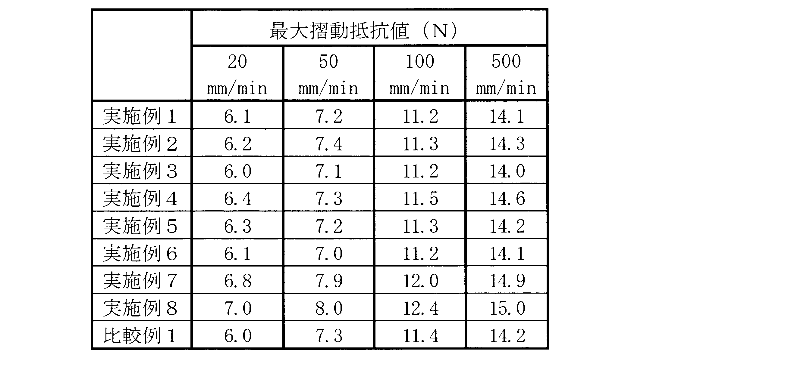
(実験2:滅菌済み注射筒基準に規定された圧力試験)
シリンジ用外筒の形成材料として、ポリプロピレン(日本ポリケム株式会社製)を用いて、射出成形により、図5に示す形状のシリンジ用外筒を作製した。シリンジ用外筒の円筒部分の内径は、29mm、長さは、121mmであった。また、プランジャーの形成材料として、ポリプロピレン(日本ポリケム株式会社製)を用いて、射出成形により、図5に示す形状のプランジャーを作製した。
そして、上記のシリンジ用外筒、実施例1~8及び比較例1の各ガスケット、上記のプランジャーを組み立て、シリンジを作製した。
滅菌済みのプラスチック製の注射筒であり、そのまま直ちに使用でき、かつ、1回限りの使用で使い捨てる滅菌済み注射筒基準(平成10年12月11日医薬発第1079号医薬安全局長通知)における圧力試験に規定されている試験を実施した。その結果を表1に示した。
なお、試験におけるサンプル数は5とし、全て適合した場合、「適合」とした。 (Experiment 2: Pressure test defined in the sterile syringe standard)
A syringe outer cylinder having a shape shown in FIG. 5 was produced by injection molding using polypropylene (manufactured by Nippon Polychem Co., Ltd.) as a forming material of the outer cylinder for syringe. The inner diameter of the cylindrical portion of the syringe outer cylinder was 29 mm, and the length was 121 mm. Moreover, the plunger of the shape shown in FIG. 5 was produced by injection molding using polypropylene (manufactured by Nippon Polychem Co., Ltd.) as a plunger forming material.
The syringe outer cylinder, the gaskets of Examples 1 to 8 and Comparative Example 1, and the plunger were assembled to produce a syringe.
A sterilized plastic syringe barrel that can be used immediately as it is, and can be used for one-time use only. The sterilized syringe cylinder standard (December 11, 1998 from the Pharmaceutical Safety Bureau No. 1079) The test specified in the pressure test was performed. The results are shown in Table 1.
In addition, the number of samples in the test was set to 5 and when all matched, it was set as “adapted”.
(実験3:高浸透性液体密封性試験)
シリンジ用外筒の形成材料として、ポリプロピレン(日本ポリケム株式会社製)を用いて、射出成形により、図5に示す形状のシリンジ用外筒を作製した。シリンジ用外筒の円筒部分の内径は、29mm、長さは、121mmであった。また、プランジャーの形成材料として、ポリプロピレン(日本ポリケム株式会社製)を用いて、射出成形により、図5に示す形状のプランジャーを作製した。
そして、上記のシリンジ用外筒、実施例1~8及び比較例1の各ガスケット、上記のプランジャーを組み立て、シリンジを作製した。
その後、プラスチック製軟包材ヒートシール部の密封性試験に用いられるエージレス(登録商標)チェッカー(三菱瓦斯化学株式会社製)を用い、密封性試験(シリンジの先端部に封止部材を嵌めて40mLを密封)を実施した。室温で一晩放置し、ガスケット摺動部からの液漏れを目視観察した結果を表1に示した。
なお、試験におけるサンプル数は5とし、全て適合した場合、「適合」とした。 (Experiment 3: High permeability liquid sealing test)
A syringe outer cylinder having a shape shown in FIG. 5 was produced by injection molding using polypropylene (manufactured by Nippon Polychem Co., Ltd.) as a forming material of the outer cylinder for syringe. The inner diameter of the cylindrical portion of the syringe outer cylinder was 29 mm, and the length was 121 mm. Moreover, the plunger of the shape shown in FIG. 5 was produced by injection molding using polypropylene (manufactured by Nippon Polychem Co., Ltd.) as a plunger forming material.
The syringe outer cylinder, the gaskets of Examples 1 to 8 and Comparative Example 1, and the plunger were assembled to produce a syringe.
Then, using AGELESS (registered trademark) checker (manufactured by Mitsubishi Gas Chemical Co., Ltd.) used for the sealing test of the plastic soft packaging material heat seal part, a sealing member was fitted into the tip of the syringe and 40 mL Was sealed). Table 1 shows the results of visually observing the liquid leakage from the gasket sliding portion after standing at room temperature overnight.
In addition, the number of samples in the test was set to 5 and when all matched, it was set as “adapted”.
(実験4:固着試験)
シリンジ用外筒の形成材料として、ポリプロピレン(日本ポリケム株式会社製)を用いて、射出成形により、図5に示す形状のシリンジ用外筒を作製した。シリンジ用外筒の円筒部分の内径は、29mm、長さは、121mmであった。また、プランジャーの形成材料として、ポリプロピレン(日本ポリケム株式会社製)を用いて、射出成形により、図5に示す形状のプランジャーを作製した。
そして、上記のシリンジ用外筒、実施例1及び7、比較例1の各ガスケット、上記のプランジャーを組み立て、シリンジを作製した。その後、40℃、60℃、80℃恒温槽内で各々1日、さらに60℃恒温槽内で10日、20日、30日各々静置した。静置後のサンプルについて、ガスケットのシリンジ用外筒への固着度を評価するために、各シリンジの初期摺動抵抗値を、オートグラフ(機種名 EZ-Test、島津製作所株式会社製)により測定した。具体的には、シリンジの先端およびプランジャーの後端をオートグラフの測定対象物固定部に固定し、プランジャーを100mm/minの速度で60mm降下させたときの初期摺動抵抗値(N)を計測したところ、表4に示すような結果となった。 (Experiment 4: Adhesion test)
A syringe outer cylinder having a shape shown in FIG. 5 was produced by injection molding using polypropylene (manufactured by Nippon Polychem Co., Ltd.) as a forming material of the outer cylinder for syringe. The inner diameter of the cylindrical portion of the syringe outer cylinder was 29 mm, and the length was 121 mm. Moreover, the plunger of the shape shown in FIG. 5 was produced by injection molding using polypropylene (manufactured by Nippon Polychem Co., Ltd.) as a plunger forming material.
Then, the syringe outer cylinder, the gaskets of Examples 1 and 7, Comparative Example 1 and the plunger were assembled to produce a syringe. Then, it stood still in a 40 degreeC, 60 degreeC, and 80 degreeC thermostat for 1 day, respectively, and also in a 60 degreeC thermostat for 10 days, 20 days, and 30 days. Measure the initial sliding resistance value of each syringe with an autograph (model name EZ-Test, manufactured by Shimadzu Corporation) to evaluate the degree of adhesion of the gasket to the outer cylinder for syringes of the sample after standing. did. Specifically, the initial sliding resistance value (N) when the tip of the syringe and the rear end of the plunger are fixed to the measurement object fixing part of the autograph and the plunger is lowered by 60 mm at a speed of 100 mm / min. Was measured and the results shown in Table 4 were obtained.

(実験5:不溶性微粒子試験)
シリンジ用外筒の形成材料として、ポリプロピレン(日本ポリケム株式会社製)を用いて、射出成形により、図5に示す形状のシリンジ用外筒を作製した。シリンジ用外筒の円筒部分の内径は、29mm、長さは、121mmであった。また、プランジャーの形成材料として、ポリプロピレン(日本ポリケム株式会社製)を用いて、射出成形により、図5に示す形状のプランジャーを作製した。 そして、上記のシリンジ用外筒、実施例1及び7、比較例1の各ガスケット、上記のプランジャーを組み立て、シリンジを作製した。
その後、蒸留水40mLを注射筒内へ注入し、注射筒の先端部に封止部材を嵌めて密封し、オートクレーブ滅菌を行い、プレフィルドシリンジを製造した後、該プレフィルドシリンジを10分間激しく振とう後の精製水中の不溶性微粒子を測定した。結果を表5に示した。 (Experiment 5: Insoluble particulate test)
A syringe outer cylinder having a shape shown in FIG. 5 was produced by injection molding using polypropylene (manufactured by Nippon Polychem Co., Ltd.) as a forming material of the outer cylinder for syringe. The inner diameter of the cylindrical portion of the syringe outer cylinder was 29 mm, and the length was 121 mm. Moreover, the plunger of the shape shown in FIG. 5 was produced by injection molding using polypropylene (manufactured by Nippon Polychem Co., Ltd.) as a plunger forming material. Then, the syringe outer cylinder, the gaskets of Examples 1 and 7, Comparative Example 1 and the plunger were assembled to produce a syringe.
Thereafter, 40 mL of distilled water is poured into the syringe barrel, a sealing member is fitted to the tip of the syringe barrel and sealed, autoclave sterilized, a prefilled syringe is manufactured, and then the prefilled syringe is shaken vigorously for 10 minutes. Insoluble fine particles in the purified water were measured. The results are shown in Table 5.
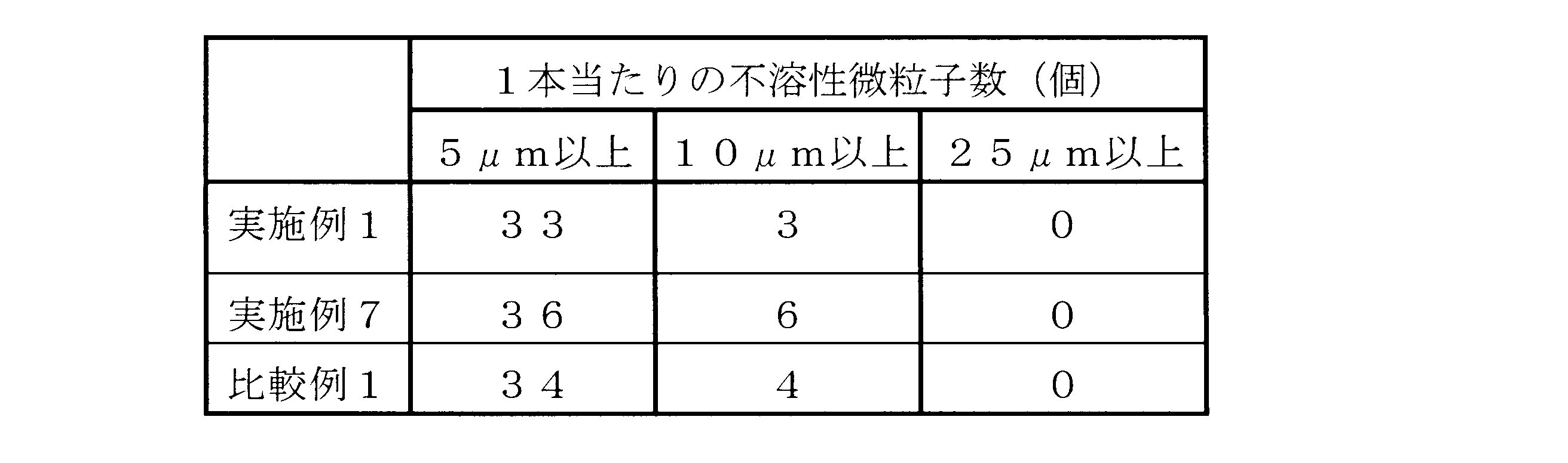
(実験6:シリンジポンプを用いた流量精度評価試験)
シリンジポンプ(TE-331、テルモ株式会社製)を用い、シリンジの流量精度評価を実施した。シリンジ用外筒の形成材料として、ポリプロピレン(日本ポリケム株式会社製)を用いて、射出成形により、図5に示す形状のシリンジ用外筒を作製した。シリンジ用外筒の円筒部分の内径は、29mm、長さは、121mmであった。また、プランジャーの形成材料として、ポリプロピレン(日本ポリケム株式会社製)を用いて、射出成形により、図5に示す形状のプランジャーを作製した。
そして、上記のシリンジ用外筒、実施例1及び7、比較例1の各ガスケット、上記のプランジャーを組み立て、シリンジを作製した。
その後、精製水40mLを注射筒内へ注入し、注射筒の先端部に封止部材を嵌めて密封し、オートクレーブ滅菌を行った後、各シリンジをシリンジポンプへセットして、5mL/hの流量で精製水を8時間吐出させ、電子天秤を用いて、その重量を30秒間隔で経時的に測定したところ、実施例1及び7、比較例1の各ガスケットは安定した吐出であることが確認された。 (Experiment 6: Flow rate accuracy evaluation test using a syringe pump)
A syringe pump (TE-331, manufactured by Terumo Corporation) was used to evaluate the flow rate accuracy of the syringe. A syringe outer cylinder having a shape shown in FIG. 5 was produced by injection molding using polypropylene (manufactured by Nippon Polychem Co., Ltd.) as a forming material of the outer cylinder for syringe. The inner diameter of the cylindrical portion of the syringe outer cylinder was 29 mm, and the length was 121 mm. Moreover, the plunger of the shape shown in FIG. 5 was produced by injection molding using polypropylene (manufactured by Nippon Polychem Co., Ltd.) as a plunger forming material.
Then, the syringe outer cylinder, the gaskets of Examples 1 and 7, Comparative Example 1 and the plunger were assembled to produce a syringe.
Thereafter, 40 mL of purified water is injected into the syringe, and a sealing member is fitted and sealed at the tip of the syringe, and after autoclaving, each syringe is set in a syringe pump and a flow rate of 5 mL / h. Purified water was discharged for 8 hours and the weight was measured over time using an electronic balance at 30 second intervals. As a result, it was confirmed that the gaskets of Examples 1 and 7 and Comparative Example 1 were stably discharged. It was done.
本発明の摺動性被覆層保有医療用具は、以下のものである。
(1) 医療用部材内面もしくは体腔内面に接触して移動する医療用具であって、該医療用具は、前記医療用部材もしくは体腔と接触する部分に設けられた摺動性被覆層を備え、該摺動性被覆層は、固体微粒子を含まず、ビニル基を有するシリコーンとケイ素原子と結合した水素基を有するシリコーンとの付加反応物であるシリコーン系樹脂を含有する組成物からなるものである摺動性被覆層保有医療用具。 The medical device having a slidable coating layer of the present invention is as follows.
(1) A medical device that moves in contact with an inner surface of a medical member or an inner surface of a body cavity, the medical device including a slidable coating layer provided on a portion that contacts the medical member or the body cavity, The slidable coating layer does not contain solid fine particles, and is made of a composition containing a silicone resin that is an addition reaction product of a silicone having a vinyl group and a silicone having a hydrogen group bonded to a silicon atom. A medical device with a mobile coating layer.
そして、本発明の実施態様は、以下のものであってもよい。
(2) 前記ビニル基を有するシリコーンは、乳化重合法で調製されたものである上記(1)に記載の摺動性被覆層保有医療用具。
(3) 前記ビニル基を有するシリコーンは、分散乳化法で調製されたものである上記(1)に記載の摺動性被覆層保有医療用具。
(4) 前記組成物は、スズ系化合物を含有しないものである上記(1)ないし(3)のいずれかに記載の摺動性被覆層保有医療用具。
(5) 前記組成物は、白金族金属系触媒を含有するものである上記(1)ないし(4)のいずれかに記載の摺動性被覆層保有医療用具。
(6) 前記組成物の前記シリコーン系樹脂は、前記ビニル基を有するシリコーンの前記ビニル基と、前記ケイ素原子と結合した水素基を有するシリコーンの前記水素基と結合しているケイ素とのヒドロシリル化により結合したシリコーン系樹脂である上記(1)ないし(5)のいずれかに記載の摺動性被覆層保有医療用具。
(7) 前記ケイ素原子と結合した水素基を有するシリコーンは、両末端にトリメチルシリル基を有するポリメチルハイドロシロキサンのホモポリマー、あるいはコポリマーである上記(1)ないし(6)のいずれかに記載の摺動性被覆層保有医療用具。
(8) 前記ケイ素原子と結合した水素基を有するシリコーンは、両末端にケイ素原子と結合した水素基を有するポリジメチルシロキサンのホモポリマー、あるいはコポリマーである上記(1)ないし(8)のいずれかに記載の摺動性被覆層保有医療用具。
(9) 前記ビニル基を有するシリコーンは、ビニル基を有するシロキサンまたはシランである上記(1)ないし(8)のいずれかに記載の摺動性被覆層保有医療用具。
(10) 前記組成物は、アルキルアルコキシシランまたはフェニルアルコキシシランを含有し、さらに、グリシドキシアルキルアルコキシシランを含有している上記(1)ないし(9)のいずれかに記載の摺動性被覆層保有医療用具。
(11) 前記組成物は、ウレイド基またはウレイレン基を有するアルコキシシラン、または/およびアミノ基を有するアルコキシシランとカルボン酸無水物との反応生成物を含有している上記(1)ないし(10)のいずれかに記載の摺動性被覆層保有医療用具。
(12) 前記シリコーン系樹脂は、熱硬化性型シリコーン系樹脂である上記(1)ないし(11)のいずれかに記載の摺動性被覆層保有医療用具。
(13) 前記被覆層は、厚さが1~30μmである上記(1)ないし(12)のいずれかに記載の摺動性被覆層保有医療用具。
(14) 前記被覆層は、初期摺動抵抗値が動的摺動抵抗値の最高値以下である上記(13)に記載の摺動性被覆層保有医療用具。
(15) 前記医療用具は、ガイドワイヤまたはカテーテルである上記(1)ないし(14)のいずれかに記載の摺動性被覆層保有医療用具。
(16) 前記医療用部材は、シリンジ用外筒であり、前記医療用具は、前記シリンジ用外筒内に摺動可能に収納されるシリンジ用ガスケットであり、該ガスケットは、弾性体からなるガスケット本体と、少なくとも前記シリンジ用外筒と接触する部分に設けられた前記摺動性被覆層を備えている上記(1)ないし(14)のいずれかに記載の摺動性被覆層保有医療用具。
(17) 前記医療用部材は、プラスチック製シリンジ外筒であり、前記医療用具は、前記プラスチック製シリンジ外筒用のガスケットである上記(16)に記載の摺動性被覆層保有医療用具。 And the following may be sufficient as the embodiment of this invention.
(2) The medical device having a slidable coating layer according to (1), wherein the silicone having a vinyl group is prepared by an emulsion polymerization method.
(3) The medical device having a slidable coating layer according to (1), wherein the silicone having a vinyl group is prepared by a dispersion emulsification method.
(4) The medical device having a slidable coating layer according to any one of (1) to (3), wherein the composition does not contain a tin-based compound.
(5) The medical device having a slidable coating layer according to any one of (1) to (4), wherein the composition contains a platinum group metal catalyst.
(6) The silicone resin of the composition is hydrosilylated between the vinyl group of the silicone having the vinyl group and the silicon bonded to the hydrogen group of the silicone having a hydrogen group bonded to the silicon atom. The medical device having a slidable coating layer according to any one of (1) to (5), wherein the medical device is a silicone-based resin bonded together.
(7) The silicone according to any one of (1) to (6), wherein the silicone having a hydrogen group bonded to a silicon atom is a homopolymer or copolymer of polymethylhydrosiloxane having trimethylsilyl groups at both ends. A medical device with a mobile coating layer.
(8) Any of the above (1) to (8), wherein the silicone having a hydrogen group bonded to a silicon atom is a homopolymer or copolymer of polydimethylsiloxane having a hydrogen group bonded to a silicon atom at both ends. A medical device having a slidable coating layer as described in 1.
(9) The medical device having a slidable coating layer according to any one of (1) to (8), wherein the silicone having a vinyl group is siloxane or silane having a vinyl group.
(10) The slidable coating according to any one of (1) to (9), wherein the composition contains alkylalkoxysilane or phenylalkoxysilane, and further contains glycidoxyalkylalkoxysilane. Layer-owned medical device.
(11) The above composition (1) to (10) containing a reaction product of an alkoxysilane having a ureido group or a ureylene group, or / and an alkoxysilane having an amino group and a carboxylic acid anhydride. A medical device having a slidable coating layer according to any one of the above.
(12) The slidable coating layer-containing medical device according to any one of (1) to (11), wherein the silicone resin is a thermosetting silicone resin.
(13) The medical device having a slidable coating layer according to any one of (1) to (12), wherein the coating layer has a thickness of 1 to 30 μm.
(14) The slidable coating layer-containing medical device according to (13), wherein the coating layer has an initial sliding resistance value that is equal to or less than a maximum value of a dynamic sliding resistance value.
(15) The medical device having a slidable coating layer according to any one of (1) to (14), wherein the medical device is a guide wire or a catheter.
(16) The medical member is a syringe outer cylinder, the medical device is a syringe gasket slidably accommodated in the syringe outer cylinder, and the gasket is made of an elastic body. The medical device having a slidable coating layer according to any one of the above (1) to (14), comprising a slidable coating layer provided on a main body and at least a portion in contact with the outer cylinder for a syringe.
(17) The medical device having a slidable coating layer according to (16), wherein the medical member is a plastic syringe outer cylinder, and the medical device is a gasket for the plastic syringe outer cylinder.
また、本発明のシリンジは、以下のものである。
(18) シリンジ用外筒と、上記(16)または(17)の摺動性被覆層保有医療用具でありかつ前記外筒内に摺動可能に収納されたシリンジ用ガスケットと、前記ガスケットに取り付けられた、あるいは取り付け可能なプランジャーとを有するシリンジ。
(19) 前記シリンジは、薬液が充填されたものである上記(18)に記載のシリンジ。
(20) 前記外筒内での前記ガスケットの低速摺動時(100mm/min)における動的摺動抵抗値が20N以下である上記(18)または(19)に記載のシリンジ。
(21) 前記外筒は、プラスチック製外筒である上記(18)ないし(20)のいずれかに記載のシリンジ。 The syringe of the present invention is as follows.
(18) An outer cylinder for syringe, a syringe gasket having the slidable coating layer-containing medical device of (16) or (17) and slidably accommodated in the outer cylinder, and attached to the gasket Syringe with attached or attachable plunger.
(19) The syringe according to (18), wherein the syringe is filled with a chemical solution.
(20) The syringe according to (18) or (19), wherein a dynamic sliding resistance value at the time of low-speed sliding of the gasket in the outer cylinder (100 mm / min) is 20 N or less.
(21) The syringe according to any one of (18) to (20), wherein the outer cylinder is a plastic outer cylinder.
Claims (21)
- 医療用部材内面もしくは体腔内面に接触して移動する医療用具であって、該医療用具は、前記医療用部材もしくは体腔と接触する部分に設けられた摺動性被覆層を備え、該摺動性被覆層は、固体微粒子を含まず、ビニル基を有するシリコーンとケイ素原子と結合した水素基を有するシリコーンとの付加反応物であるシリコーン系樹脂を含有する組成物からなるものであることを特徴とする摺動性被覆層保有医療用具。 A medical device that moves in contact with an inner surface of a medical member or an inner surface of a body cavity, the medical device comprising a slidable coating layer provided on a portion that contacts the medical member or body cavity, and the slidability The coating layer does not contain solid fine particles and is composed of a composition containing a silicone resin that is an addition reaction product of a silicone having a vinyl group and a silicone having a hydrogen group bonded to a silicon atom. A medical device possessing a slidable coating layer.
- 前記ビニル基を有するシリコーンは、乳化重合法で調製されたものである請求項1に記載の摺動性被覆層保有医療用具。 The medical device having a slidable coating layer according to claim 1, wherein the silicone having a vinyl group is prepared by an emulsion polymerization method.
- 前記ビニル基を有するシリコーンは、分散乳化法で調製されたものである請求項1に記載の摺動性被覆層保有医療用具。 The medical device having a slidable coating layer according to claim 1, wherein the silicone having a vinyl group is prepared by a dispersion emulsification method.
- 前記組成物は、スズ系化合物を含有しないものである請求項1ないし3のいずれかに記載の摺動性被覆層保有医療用具。 The slidable coating layer-containing medical device according to any one of claims 1 to 3, wherein the composition does not contain a tin-based compound.
- 前記組成物は、白金族金属系触媒を含有するものである請求項1ないし4のいずれかに記載の摺動性被覆層保有医療用具。 The medical device having a slidable coating layer according to any one of claims 1 to 4, wherein the composition contains a platinum group metal catalyst.
- 前記組成物の前記シリコーン系樹脂は、前記ビニル基を有するシリコーンの前記ビニル基と、前記ケイ素原子と結合した水素基を有するシリコーンの前記水素基と結合しているケイ素とのヒドロシリル化により結合したシリコーン系樹脂である請求項1ないし5のいずれかに記載の摺動性被覆層保有医療用具。 The silicone resin of the composition is bonded by hydrosilylation of the vinyl group of the silicone having the vinyl group and the silicon bonded to the hydrogen group of the silicone having a hydrogen group bonded to the silicon atom. The medical device having a slidable coating layer according to any one of claims 1 to 5, which is a silicone resin.
- 前記ケイ素原子と結合した水素基を有するシリコーンは、両末端にトリメチルシリル基を有するポリメチルハイドロシロキサンのホモポリマー、あるいはコポリマーである請求項1ないし6のいずれかに記載の摺動性被覆層保有医療用具。 The slidable covering layer-containing medical device according to any one of claims 1 to 6, wherein the silicone having a hydrogen group bonded to a silicon atom is a homopolymer or copolymer of polymethylhydrosiloxane having trimethylsilyl groups at both ends. Tools.
- 前記ケイ素原子と結合した水素基を有するシリコーンは、両末端にケイ素原子と結合した水素基を有するポリジメチルシロキサンのホモポリマー、あるいはコポリマーである請求項1ないし8のいずれかに記載の摺動性被覆層保有医療用具。 The slidability according to any one of claims 1 to 8, wherein the silicone having a hydrogen group bonded to a silicon atom is a polydimethylsiloxane homopolymer or copolymer having a hydrogen group bonded to a silicon atom at both ends. Medical device with coating layer.
- 前記ビニル基を有するシリコーンは、ビニル基を有するシロキサンまたはシランである請求項1ないし8のいずれかに記載の摺動性被覆層保有医療用具。 The medical device having a slidable coating layer according to any one of claims 1 to 8, wherein the silicone having a vinyl group is siloxane or silane having a vinyl group.
- 前記組成物は、アルキルアルコキシシランまたはフェニルアルコキシシランを含有し、さらに、グリシドキシアルキルアルコキシシランを含有している請求項1ないし9のいずれかに記載の摺動性被覆層保有医療用具。 The medical device having a slidable coating layer according to any one of claims 1 to 9, wherein the composition contains alkyl alkoxysilane or phenyl alkoxysilane, and further contains glycidoxyalkylalkoxysilane.
- 前記組成物は、ウレイド基またはウレイレン基を有するアルコキシシラン、または/およびアミノ基を有するアルコキシシランとカルボン酸無水物との反応生成物を含有している請求項1ないし10のいずれかに記載の摺動性被覆層保有医療用具。 11. The composition according to claim 1, wherein the composition contains a reaction product of an alkoxysilane having a ureido group or a ureylene group, or / and an alkoxysilane having an amino group and a carboxylic acid anhydride. Medical device with slidable coating layer.
- 前記シリコーン系樹脂は、熱硬化性型シリコーン系樹脂である請求項1ないし11のいずれかに記載の摺動性被覆層保有医療用具。 The medical device having a slidable coating layer according to any one of claims 1 to 11, wherein the silicone resin is a thermosetting silicone resin.
- 前記被覆層は、厚さが1~30μmである請求項1ないし12のいずれかに記載の摺動性被覆層保有医療用具。 13. The medical device having a slidable coating layer according to claim 1, wherein the coating layer has a thickness of 1 to 30 μm.
- 前記被覆層は、初期摺動抵抗値が動的摺動抵抗値の最高値以下である請求項13に記載の摺動性被覆層保有医療用具。 The medical device having a slidable coating layer according to claim 13, wherein the coating layer has an initial sliding resistance value equal to or less than a maximum value of a dynamic sliding resistance value.
- 前記医療用具は、ガイドワイヤまたはカテーテルである請求項1ないし14のいずれかに記載の摺動性被覆層保有医療用具。 The medical device having a slidable coating layer according to any one of claims 1 to 14, wherein the medical device is a guide wire or a catheter.
- 前記医療用部材は、シリンジ用外筒であり、前記医療用具は、前記シリンジ用外筒内に摺動可能に収納されるシリンジ用ガスケットであり、該ガスケットは、弾性体からなるガスケット本体と、少なくとも前記シリンジ用外筒と接触する部分に設けられた前記摺動性被覆層を備えている請求項1ないし14のいずれかに記載の摺動性被覆層保有医療用具。 The medical member is a syringe outer cylinder, the medical device is a syringe gasket slidably accommodated in the syringe outer cylinder, and the gasket includes a gasket body made of an elastic body; The medical device having a slidable coating layer according to any one of claims 1 to 14, further comprising the slidable coating layer provided at least in a portion in contact with the syringe outer cylinder.
- 前記医療用部材は、プラスチック製シリンジ外筒であり、前記医療用具は、前記プラスチック製シリンジ外筒用のガスケットである請求項16に記載の摺動性被覆層保有医療用具。 The medical device having a slidable coating layer according to claim 16, wherein the medical member is a plastic syringe outer cylinder, and the medical device is a gasket for the plastic syringe outer cylinder.
- シリンジ用外筒と、請求項16または17の摺動性被覆層保有医療用具でありかつ前記外筒内に摺動可能に収納されたシリンジ用ガスケットと、前記ガスケットに取り付けられた、あるいは取り付け可能なプランジャーとを有することを特徴とするシリンジ。 An outer cylinder for a syringe, a syringe gasket having a slidable covering layer according to claim 16 or 17 and slidably accommodated in the outer cylinder, and attached to or attachable to the gasket And a plunger.
- 前記シリンジは、薬液が充填されたものである請求項18に記載のシリンジ。 The syringe according to claim 18, wherein the syringe is filled with a chemical solution.
- 前記外筒内での前記ガスケットの低速摺動時(100mm/min)における動的摺動抵抗値が20N以下である請求項18または19に記載のシリンジ。 The syringe according to claim 18 or 19, wherein a dynamic sliding resistance value at the time of low-speed sliding (100 mm / min) of the gasket in the outer cylinder is 20 N or less.
- 前記外筒は、プラスチック製外筒である請求項18ないし20のいずれかに記載のシリンジ。 The syringe according to any one of claims 18 to 20, wherein the outer cylinder is a plastic outer cylinder.
Priority Applications (4)
| Application Number | Priority Date | Filing Date | Title |
|---|---|---|---|
| EP11762798.4A EP2554205B1 (en) | 2010-03-30 | 2011-03-28 | Medical device with slideable coating, and syringe |
| JP2012508320A JP5930959B2 (en) | 2010-03-30 | 2011-03-28 | Medical device and syringe with slidable coating layer |
| CN201180015853.7A CN102821804B (en) | 2010-03-30 | 2011-03-28 | Medical device with slideable coating, and syringe |
| US13/628,833 US8742032B2 (en) | 2010-03-30 | 2012-09-27 | Medical appliance having a slidable coating layer and syringe |
Applications Claiming Priority (2)
| Application Number | Priority Date | Filing Date | Title |
|---|---|---|---|
| JP2010076814 | 2010-03-30 | ||
| JP2010-076814 | 2010-03-30 |
Related Child Applications (1)
| Application Number | Title | Priority Date | Filing Date |
|---|---|---|---|
| US13/628,833 Continuation US8742032B2 (en) | 2010-03-30 | 2012-09-27 | Medical appliance having a slidable coating layer and syringe |
Publications (1)
| Publication Number | Publication Date |
|---|---|
| WO2011122574A1 true WO2011122574A1 (en) | 2011-10-06 |
Family
ID=44712269
Family Applications (1)
| Application Number | Title | Priority Date | Filing Date |
|---|---|---|---|
| PCT/JP2011/057679 WO2011122574A1 (en) | 2010-03-30 | 2011-03-28 | Medical device with slideable coating, and syringe |
Country Status (5)
| Country | Link |
|---|---|
| US (1) | US8742032B2 (en) |
| EP (1) | EP2554205B1 (en) |
| JP (2) | JP5930959B2 (en) |
| CN (1) | CN102821804B (en) |
| WO (1) | WO2011122574A1 (en) |
Cited By (9)
| Publication number | Priority date | Publication date | Assignee | Title |
|---|---|---|---|---|
| US20130122314A1 (en) * | 2011-11-15 | 2013-05-16 | Duan Li Ou | Rapid cure silicone lubricious coatings |
| WO2016056149A1 (en) * | 2014-10-07 | 2016-04-14 | 有限会社コーキ・エンジニアリング | Gasket using slidable medical silicone rubber, and syringe using said gasket |
| US9468726B2 (en) | 2008-01-15 | 2016-10-18 | West Pharmaceutical Services, Inc. | Syringe with co-molded hub and cannula |
| JPWO2015151671A1 (en) * | 2014-03-31 | 2017-04-13 | テルモ株式会社 | Syringe gasket and syringe equipped with the gasket |
| WO2018066378A1 (en) * | 2016-10-05 | 2018-04-12 | テルモ株式会社 | Liquid medicine administration device and control method for liquid medicine administration device |
| JPWO2017169466A1 (en) * | 2016-03-31 | 2019-02-07 | テルモ株式会社 | Liquid for medical device coating and medical device with slidable coating |
| WO2021065739A1 (en) | 2019-09-30 | 2021-04-08 | 株式会社朝日ラバー | Slidable rubber material having amino-modified interfacial modification layer, and method for producing said slidable rubber material |
| EP3858405A1 (en) * | 2012-06-01 | 2021-08-04 | Novartis AG | Syringe |
| WO2023031580A1 (en) * | 2021-09-03 | 2023-03-09 | Nicoventures Trading Limited | Reservoir for a refilling device, device and method for refilling an article of an aerosol provision system, nozzle for fluid dispensing, and refillable article for an electronic aerosol provision system |
Families Citing this family (16)
| Publication number | Priority date | Publication date | Assignee | Title |
|---|---|---|---|---|
| CN103582498B (en) | 2011-03-30 | 2015-04-22 | 泰尔茂株式会社 | Medical instrument with slidable coating layer, and syringe |
| US8883245B2 (en) * | 2013-03-13 | 2014-11-11 | Ethicon, Inc. | Method of coating surgical needles |
| JP2014223149A (en) * | 2013-05-15 | 2014-12-04 | 住友ゴム工業株式会社 | Gasket for syringe |
| JP6270265B2 (en) * | 2014-02-05 | 2018-01-31 | 住友ゴム工業株式会社 | Medical syringe, gasket applied to the syringe, and manufacturing method thereof |
| CA2979044C (en) | 2015-03-10 | 2022-10-18 | Regeneron Pharmaceuticals, Inc. | Aseptic piercing system and method |
| EP3318614B1 (en) * | 2015-07-01 | 2020-02-19 | Terumo Kabushiki Kaisha | Coating agent and medical instrument surface treated with coating agent |
| AU2016356717B2 (en) | 2015-11-18 | 2022-09-29 | Sio2 Medical Products, Inc. | Pharmaceutical package for ophthalmic formulations |
| WO2018218013A2 (en) | 2017-05-24 | 2018-11-29 | Sio2 Medical Products, Inc. | Sterilizable pharmaceutical package for ophthalmic formulations |
| EP3557596B1 (en) | 2016-12-19 | 2024-04-03 | Tanaka Kikinzoku Kogyo K.K. | Tape-like contact and method for manufacturing same |
| WO2018204779A1 (en) | 2017-05-05 | 2018-11-08 | Regeneron Pharmaceuticals, Inc. | Auto-injector |
| FR3075056A1 (en) | 2017-12-14 | 2019-06-21 | Etablissement Francais Du Sang | CRYORESISTANT INJECTION DEVICE READY FOR USE |
| DE102018122001A1 (en) * | 2018-09-10 | 2020-03-12 | Schott Ag | Packaging with sliding layer and process for pharmaceutical and cosmetic substances and preparation for its manufacture |
| JP7074642B2 (en) * | 2018-10-29 | 2022-05-24 | 信越化学工業株式会社 | Silicone emulsion composition |
| JP7241165B2 (en) * | 2019-03-26 | 2023-03-16 | テルモ株式会社 | Syringe cap, syringe assembly and prefilled syringe |
| USD950720S1 (en) * | 2020-11-20 | 2022-05-03 | Becton, Dickinson And Company | Medical stopper |
| USD1007676S1 (en) | 2021-11-16 | 2023-12-12 | Regeneron Pharmaceuticals, Inc. | Wearable autoinjector |
Citations (4)
| Publication number | Priority date | Publication date | Assignee | Title |
|---|---|---|---|---|
| JPH06183555A (en) * | 1992-12-22 | 1994-07-05 | Siegel:Kk | Shock absorber |
| JPH07138480A (en) * | 1993-11-15 | 1995-05-30 | Shin Etsu Chem Co Ltd | Coating film-forming silicone resin composition and silicone resin molded body |
| JPH11350361A (en) * | 1998-04-28 | 1999-12-21 | Dow Corning Corp | Silicone-coated knitted fabric |
| WO2009084646A1 (en) * | 2007-12-28 | 2009-07-09 | Terumo Kabushiki Kaisha | Gasket for syringe and syringe comprising the gasket |
Family Cites Families (23)
| Publication number | Priority date | Publication date | Assignee | Title |
|---|---|---|---|---|
| JPS60181162A (en) | 1984-02-28 | 1985-09-14 | Toray Silicone Co Ltd | Curable organopolysiloxane composition |
| JPS6232970A (en) | 1985-08-01 | 1987-02-12 | セイコーエプソン株式会社 | Syringe |
| US4968766A (en) * | 1989-01-12 | 1990-11-06 | Dow Corning Corporation | Fluorosilicone compounds and compositions for adhesive release liners |
| ATE157886T1 (en) * | 1990-11-17 | 1997-09-15 | Santen Pharmaceutical Co Ltd | SYRINGE CYLINDER WITH TWO CHAMBERS |
| US5352378A (en) * | 1993-05-27 | 1994-10-04 | Minnesota Mining And Manufacturing Company | Nonflammable lubricious composition |
| DE19753766A1 (en) * | 1997-12-04 | 1999-06-17 | Schott Glas | Elongated hollow plastic body and process for its production |
| US6200627B1 (en) * | 1998-03-17 | 2001-03-13 | Becton, Dickinson And Company | Low silicone glass prefillable syringe |
| US6243938B1 (en) * | 1998-03-17 | 2001-06-12 | Becton, Dickinson And Company | Low silicone plastic prefillable syringe |
| JP2002037947A (en) | 2000-07-25 | 2002-02-06 | Mitsui Chemicals Inc | Curable composition and application thereof |
| US7176269B2 (en) | 2000-07-25 | 2007-02-13 | Mitsui Chemicals, Inc. | Curable composition and its use |
| JP2002086481A (en) | 2000-09-14 | 2002-03-26 | Terumo Corp | Method for manufacturing gasket |
| US7332227B2 (en) | 2003-03-14 | 2008-02-19 | Becton, Dickinson And Company | Non-volatile lubricant system for medical devices |
| JP4481587B2 (en) | 2003-04-25 | 2010-06-16 | テルモ株式会社 | Syringe |
| CN1715325A (en) * | 2004-06-30 | 2006-01-04 | 威海威高创新有限公司 | Soft polyvinyl-chloride plastics for disposable injector piston |
| EP1640031A3 (en) * | 2004-09-28 | 2006-06-07 | Nipro Corporation | Syringe coated with lubricant containing silicone oil and silica powder |
| JP4708013B2 (en) | 2004-12-15 | 2011-06-22 | テルモ株式会社 | Syringe |
| US7943242B2 (en) * | 2006-03-30 | 2011-05-17 | Becton, Dickinson And Company | Sealing members, articles using the same and methods of reducing sticktion |
| JP2008000287A (en) | 2006-06-21 | 2008-01-10 | Terumo Corp | Sliding composition for coating medical appliance and medical appliance with sliding coat |
| JP2008144024A (en) | 2006-12-08 | 2008-06-26 | Daikin Ind Ltd | Curable polymer composition |
| KR20090091200A (en) | 2006-12-21 | 2009-08-26 | 다우 코닝 코포레이션 | Dual curing polymers and methods for their preparation and use |
| JP2008268493A (en) * | 2007-04-19 | 2008-11-06 | Bando Chem Ind Ltd | Cleaning blade for electrophotographic equipment, and its manufacturing method |
| GB0715376D0 (en) | 2007-08-07 | 2007-09-19 | Smith & Nephew | Coating |
| JP5060873B2 (en) | 2007-08-24 | 2012-10-31 | 東レ・ダウコーニング株式会社 | Silicone pressure-sensitive adhesive composition and pressure-sensitive adhesive tape or sheet |
-
2011
- 2011-03-28 EP EP11762798.4A patent/EP2554205B1/en active Active
- 2011-03-28 CN CN201180015853.7A patent/CN102821804B/en active Active
- 2011-03-28 WO PCT/JP2011/057679 patent/WO2011122574A1/en active Application Filing
- 2011-03-28 JP JP2012508320A patent/JP5930959B2/en active Active
-
2012
- 2012-09-27 US US13/628,833 patent/US8742032B2/en active Active
-
2016
- 2016-04-26 JP JP2016088074A patent/JP2016152998A/en active Pending
Patent Citations (4)
| Publication number | Priority date | Publication date | Assignee | Title |
|---|---|---|---|---|
| JPH06183555A (en) * | 1992-12-22 | 1994-07-05 | Siegel:Kk | Shock absorber |
| JPH07138480A (en) * | 1993-11-15 | 1995-05-30 | Shin Etsu Chem Co Ltd | Coating film-forming silicone resin composition and silicone resin molded body |
| JPH11350361A (en) * | 1998-04-28 | 1999-12-21 | Dow Corning Corp | Silicone-coated knitted fabric |
| WO2009084646A1 (en) * | 2007-12-28 | 2009-07-09 | Terumo Kabushiki Kaisha | Gasket for syringe and syringe comprising the gasket |
Cited By (27)
| Publication number | Priority date | Publication date | Assignee | Title |
|---|---|---|---|---|
| US9468726B2 (en) | 2008-01-15 | 2016-10-18 | West Pharmaceutical Services, Inc. | Syringe with co-molded hub and cannula |
| CN104105765B (en) * | 2011-11-15 | 2018-03-09 | 伊西康公司 | Rapid curing siloxanes lubricant coating |
| WO2013074732A1 (en) * | 2011-11-15 | 2013-05-23 | Ethicon, Inc. | Rapid cure silicone lubricious coatings |
| CN104105765A (en) * | 2011-11-15 | 2014-10-15 | 伊西康公司 | Rapid cure silicone lubricious coatings |
| AU2012340465B2 (en) * | 2011-11-15 | 2016-04-14 | Ethicon, Inc. | Rapid cure silicone lubricious coatings |
| US11833496B2 (en) | 2011-11-15 | 2023-12-05 | Ethicon, Inc. | Rapid cure silicone lubricious coatings |
| US11224869B2 (en) | 2011-11-15 | 2022-01-18 | Ethicon, Inc. | Rapid cure silicone lubricious coatings |
| US9434857B2 (en) * | 2011-11-15 | 2016-09-06 | Ethicon, Inc. | Rapid cure silicone lubricious coatings |
| US20130122314A1 (en) * | 2011-11-15 | 2013-05-16 | Duan Li Ou | Rapid cure silicone lubricious coatings |
| RU2630802C2 (en) * | 2011-11-15 | 2017-09-13 | Этикон, Инк. | Quickly confirmed silicone lubricants |
| US11110226B2 (en) | 2012-06-01 | 2021-09-07 | Novartis Ag | Syringe |
| US11179521B2 (en) | 2012-06-01 | 2021-11-23 | Novartis Ag | Syringe |
| US11185635B2 (en) | 2012-06-01 | 2021-11-30 | Novartis Ag | Syringe |
| US11147925B2 (en) | 2012-06-01 | 2021-10-19 | Novartis Ag | Syringe |
| US11103644B2 (en) | 2012-06-01 | 2021-08-31 | Novartis Ag | Syringe |
| EP3858405A1 (en) * | 2012-06-01 | 2021-08-04 | Novartis AG | Syringe |
| JPWO2015151671A1 (en) * | 2014-03-31 | 2017-04-13 | テルモ株式会社 | Syringe gasket and syringe equipped with the gasket |
| US10456527B2 (en) | 2014-10-07 | 2019-10-29 | Coki Engineering Inc. | Gasket using medical silicone rubber having slidability, and syringe using said gasket |
| JP5977462B1 (en) * | 2014-10-07 | 2016-08-24 | 有限会社コーキ・エンジニアリング | Gasket using medical silicone rubber having slidability, syringe using the gasket, and method for producing the same |
| WO2016056149A1 (en) * | 2014-10-07 | 2016-04-14 | 有限会社コーキ・エンジニアリング | Gasket using slidable medical silicone rubber, and syringe using said gasket |
| JPWO2017169466A1 (en) * | 2016-03-31 | 2019-02-07 | テルモ株式会社 | Liquid for medical device coating and medical device with slidable coating |
| WO2018066378A1 (en) * | 2016-10-05 | 2018-04-12 | テルモ株式会社 | Liquid medicine administration device and control method for liquid medicine administration device |
| JPWO2018066378A1 (en) * | 2016-10-05 | 2019-07-25 | テルモ株式会社 | Patent application title: Drug solution administration apparatus and control method of drug solution administration apparatus |
| US11524109B2 (en) | 2016-10-05 | 2022-12-13 | Terumo Kabushiki Kaisha | Drug solution administration device and method for controlling drug solution administration device |
| WO2021065739A1 (en) | 2019-09-30 | 2021-04-08 | 株式会社朝日ラバー | Slidable rubber material having amino-modified interfacial modification layer, and method for producing said slidable rubber material |
| US11472945B2 (en) | 2019-09-30 | 2022-10-18 | Asahi Rubber Inc. | Slidable rubber material having an amino-modified interfacial modification layer, and method for producing said slidable rubber material |
| WO2023031580A1 (en) * | 2021-09-03 | 2023-03-09 | Nicoventures Trading Limited | Reservoir for a refilling device, device and method for refilling an article of an aerosol provision system, nozzle for fluid dispensing, and refillable article for an electronic aerosol provision system |
Also Published As
| Publication number | Publication date |
|---|---|
| US8742032B2 (en) | 2014-06-03 |
| CN102821804A (en) | 2012-12-12 |
| EP2554205A1 (en) | 2013-02-06 |
| EP2554205B1 (en) | 2020-04-22 |
| JP5930959B2 (en) | 2016-06-08 |
| EP2554205A4 (en) | 2015-10-28 |
| JPWO2011122574A1 (en) | 2013-07-08 |
| US20130030380A1 (en) | 2013-01-31 |
| JP2016152998A (en) | 2016-08-25 |
| CN102821804B (en) | 2015-06-10 |
Similar Documents
| Publication | Publication Date | Title |
|---|---|---|
| JP5930959B2 (en) | Medical device and syringe with slidable coating layer | |
| JP6220408B2 (en) | Syringe gasket and syringe | |
| JP5791683B2 (en) | Syringe gasket and syringe provided with the same | |
| JP2008000287A (en) | Sliding composition for coating medical appliance and medical appliance with sliding coat | |
| JP2013541375A (en) | Self-lubricating drug syringe stopper | |
| JP6401245B2 (en) | Syringe gasket and syringe equipped with the gasket | |
| JP6850792B2 (en) | Syringe gasket and syringe with it | |
| WO2016152185A1 (en) | Drug-container rubber plug and drug-containing drug container using same | |
| WO2023135884A1 (en) | Gasket for syringe and syringe provided with same |
Legal Events
| Date | Code | Title | Description |
|---|---|---|---|
| WWE | Wipo information: entry into national phase |
Ref document number: 201180015853.7 Country of ref document: CN |
|
| 121 | Ep: the epo has been informed by wipo that ep was designated in this application |
Ref document number: 11762798 Country of ref document: EP Kind code of ref document: A1 |
|
| WWE | Wipo information: entry into national phase |
Ref document number: 2012508320 Country of ref document: JP |
|
| WWE | Wipo information: entry into national phase |
Ref document number: 2011762798 Country of ref document: EP |
|
| NENP | Non-entry into the national phase |
Ref country code: DE |