WO2011121761A1 - 画像処理装置、およびそれを用いた撮像装置 - Google Patents
画像処理装置、およびそれを用いた撮像装置 Download PDFInfo
- Publication number
- WO2011121761A1 WO2011121761A1 PCT/JP2010/055862 JP2010055862W WO2011121761A1 WO 2011121761 A1 WO2011121761 A1 WO 2011121761A1 JP 2010055862 W JP2010055862 W JP 2010055862W WO 2011121761 A1 WO2011121761 A1 WO 2011121761A1
- Authority
- WO
- WIPO (PCT)
- Prior art keywords
- image
- imaging
- processing
- difference
- filter
- Prior art date
Links
- 238000012545 processing Methods 0.000 title claims abstract description 120
- 238000011084 recovery Methods 0.000 claims abstract description 63
- 238000012546 transfer Methods 0.000 claims abstract description 51
- 238000001228 spectrum Methods 0.000 claims abstract description 17
- 238000003384 imaging method Methods 0.000 claims description 147
- 230000006870 function Effects 0.000 claims description 73
- 238000003672 processing method Methods 0.000 claims description 7
- 230000010365 information processing Effects 0.000 claims description 3
- 230000004075 alteration Effects 0.000 abstract description 46
- 238000000034 method Methods 0.000 description 59
- 238000012937 correction Methods 0.000 description 57
- 230000003287 optical effect Effects 0.000 description 54
- 230000008569 process Effects 0.000 description 43
- 238000003860 storage Methods 0.000 description 20
- 238000006731 degradation reaction Methods 0.000 description 8
- 238000010586 diagram Methods 0.000 description 7
- 230000015556 catabolic process Effects 0.000 description 6
- 230000014509 gene expression Effects 0.000 description 6
- 230000003321 amplification Effects 0.000 description 5
- 238000003199 nucleic acid amplification method Methods 0.000 description 5
- 230000003595 spectral effect Effects 0.000 description 5
- 230000008859 change Effects 0.000 description 4
- 238000006243 chemical reaction Methods 0.000 description 4
- 238000001514 detection method Methods 0.000 description 4
- 230000006835 compression Effects 0.000 description 3
- 238000007906 compression Methods 0.000 description 3
- 230000006866 deterioration Effects 0.000 description 3
- 230000002093 peripheral effect Effects 0.000 description 3
- 206010010071 Coma Diseases 0.000 description 2
- 230000008901 benefit Effects 0.000 description 2
- 238000004364 calculation method Methods 0.000 description 2
- 238000004040 coloring Methods 0.000 description 2
- 238000011161 development Methods 0.000 description 2
- 230000004069 differentiation Effects 0.000 description 2
- 230000000694 effects Effects 0.000 description 2
- 238000011156 evaluation Methods 0.000 description 2
- 230000010354 integration Effects 0.000 description 2
- 230000007246 mechanism Effects 0.000 description 2
- 230000035945 sensitivity Effects 0.000 description 2
- 238000002834 transmittance Methods 0.000 description 2
- 241000255969 Pieris brassicae Species 0.000 description 1
- 230000003044 adaptive effect Effects 0.000 description 1
- 238000004458 analytical method Methods 0.000 description 1
- 201000009310 astigmatism Diseases 0.000 description 1
- 238000003705 background correction Methods 0.000 description 1
- 230000015572 biosynthetic process Effects 0.000 description 1
- 238000004891 communication Methods 0.000 description 1
- 230000003247 decreasing effect Effects 0.000 description 1
- 238000013461 design Methods 0.000 description 1
- 238000004033 diameter control Methods 0.000 description 1
- 238000009826 distribution Methods 0.000 description 1
- 230000002708 enhancing effect Effects 0.000 description 1
- 238000004519 manufacturing process Methods 0.000 description 1
- 238000012986 modification Methods 0.000 description 1
- 230000004048 modification Effects 0.000 description 1
- ORQBXQOJMQIAOY-UHFFFAOYSA-N nobelium Chemical compound [No] ORQBXQOJMQIAOY-UHFFFAOYSA-N 0.000 description 1
- 230000011514 reflex Effects 0.000 description 1
- 238000005070 sampling Methods 0.000 description 1
- 239000004065 semiconductor Substances 0.000 description 1
- 230000009466 transformation Effects 0.000 description 1
- 230000000007 visual effect Effects 0.000 description 1
Images


Classifications
-
- G06T5/73—
-
- H—ELECTRICITY
- H04—ELECTRIC COMMUNICATION TECHNIQUE
- H04N—PICTORIAL COMMUNICATION, e.g. TELEVISION
- H04N25/00—Circuitry of solid-state image sensors [SSIS]; Control thereof
- H04N25/60—Noise processing, e.g. detecting, correcting, reducing or removing noise
- H04N25/61—Noise processing, e.g. detecting, correcting, reducing or removing noise the noise originating only from the lens unit, e.g. flare, shading, vignetting or "cos4"
- H04N25/611—Correction of chromatic aberration
Definitions
- the present invention relates to an image processing apparatus that performs image processing, and more particularly to an image processing apparatus that performs image restoration (restoration).
- An image obtained by an image pickup apparatus such as a digital camera has deteriorated in image quality due to blur.
- Causes of image blurring include spherical aberration, coma aberration, field curvature, astigmatism, and the like of the imaging optical system.
- These aberrations can be expressed by a point spread function (PSF, Point Spread Function).
- An optical transfer function (OTF, Optic Transfer Function) that can be obtained by Fourier transform of a point spread function (hereinafter referred to as PSF) is information in the frequency space of aberration.
- This optical transfer function (hereinafter referred to as OTF) can be expressed by a complex number, and the absolute value of the OTF, that is, the amplitude component is called MTF (Modulation Transfer Function) and the phase component is called PTF (Phase Transfer Function).
- MTF Modulation Transfer Function
- PTF Phase Transfer Function
- each point of the image of the subject acquired via the imaging optical system is coma. It becomes an asymmetrically blurred image (degraded image) like aberration. Furthermore, since the PSF is different for each color component (for example, red, blue, green, etc.) included in the image, different blur occurs for each color component, resulting in an image (degraded image) in which the color is blurred.
- MTF amplitude component
- PTF phase component
- image restoration processing processing for correcting image degradation using information on the optical transfer function of the imaging optical system (imaging system) will be referred to as image restoration processing.
- the point spread function (PSF) of the imaging system used to acquire the degraded image g (x, y), the original image f (x, y), and g (x, y) is represented by h (x , Y), the following equation holds.
- * indicates convolution (convolution integration, sum of products), and (x, y) indicates image coordinates in real space.
- Formula 1 When Formula 1 is Fourier-transformed and converted into a display format in the frequency space, it can be expressed as Formula 2.
- H (u, v) is an optical transfer function (OTF) obtained by Fourier transform of the point spread function (PSF) h (x, y).
- G (u, v) and F (u, v) are obtained by Fourier transform of g (x, y) and f (x, y), respectively.
- (U, v) indicates a frequency (coordinate) in a two-dimensional frequency space.
- Equation 2 may be divided by H (u, v).
- Equation 4 Equation 4.
- R (x, y) f (x, y)
- R (x, y) is obtained by inverse Fourier transform of 1 / H (u, v). This R (x, y) is an image restoration filter.
- this image restoration filter is based on the optical transfer function (OTF), it is possible to correct the deterioration of the amplitude component and the phase component.
- the Wiener filter is an image restoration filter that changes the degree of restoration according to the intensity ratio (SNR, SoundSby Noise Ratio) between the input signal (image signal) and the noise signal in order to reduce noise in the input image.
- SNR SoundSby Noise Ratio
- an adjustment parameter ⁇ is provided in the image restoration filter by applying the Wiener filter.
- an image restoration filter that can change the degree of restoration of an image in a range from a filter that outputs an input image as it is (a filter that does nothing) to a filter that performs maximum image restoration (inverse filter) Disclosure.
- Patent Document 2 discloses an edge enhancement process for enhancing an edge by detecting an edge portion of an image as a method for correcting phase deterioration.
- the aberration amplitude component and the phase component are corrected (to improve the sharpness). It is necessary to correct the chromatic aberration by reducing the difference in PSF between the color components.
- the above-described Wiener filter or the image restoration filter disclosed in Patent Document 1 can correct (recover) the amplitude component and the phase component of the deteriorated image.
- difference in appearance of blur for each color component difference is not taken into consideration, not only the image restoration processing is performed, but the restored image remains colored or the coloring is enlarged was there.
- a broken line (a) and a solid line (b) in FIG. 13 are MTFs of two color components before recovery.
- a broken line (c) and a solid line (d) are MTFs after recovery of the color components represented by (a) and (b), respectively.
- the difference between the MTFs (c) and (d) of the two color components after the recovery is larger than the difference between the MTFs (a) and (b) of the two color components before the recovery. It spreads. Since the MTF is improved in both (c) and (d) after recovery compared to (a) and (b), the sharpness of the image is improved. However, the difference in MTF between each color component that appears in the image as colored (chromatic aberration) increases.
- an object of the present invention is to provide an image processing apparatus capable of reducing chromatic aberration while improving the sharpness of an image.
- Image acquisition means for acquiring an input image
- Image recovery processing means for generating a recovered image by calculating the input image and an image recovery filter based on a transfer function of an imaging system used to form a subject image as the input image
- the image recovery filter recovers such that the difference in spectrum between the two color components in the recovered image is smaller than the difference in spectrum between the two color components in the input image.
- Explanatory drawing of the image processing method which is an Example of this invention Explanatory drawing of the image restoration filter used with the image processing method of this invention Explanatory drawing when matching the difference in MTF of each color component
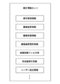
- Explanatory drawing when reducing the difference in MTF of each color component 1 is a block diagram showing a configuration of an imaging apparatus equipped with an image processing apparatus that is Embodiment 1 of the present invention.
- Explanatory diagram regarding selection and correction of image restoration filter Flowchart of image processing of embodiment 1
- the figure which shows the MTF change before and after image processing Illustration of edge enhancement filter Edge cross section with edge enhancement filter applied Schematic configuration diagram of an image processing system Explanation of correction information
- an input image is acquired.
- step S12 the imaging condition of the input image acquired in step S11 is acquired.
- step 13 an image restoration filter corresponding to the imaging condition is selected from the memory. If the imaging conditions are different from those prepared in advance in the memory, they can be appropriately corrected and used.
- an image restoration process correction process
- an image restoration process correction process
- the corrected image corrected in step S14 is output as an output image.
- the image restoration filter used in step 13 is generated based on the optical transfer function (OTF) of the imaging optical system (imaging system) and the chromatic aberration correction coefficient.
- MTF is the absolute value (amplitude component) of the transfer function of the imaging system (optical transfer function of the imaging optical system), but if the subject is a white point light source, the MTF can also be taken as the spectrum of the image.
- An image acquired by the image acquisition process (hereinafter referred to as an input image) is a digital image obtained by imaging with an imaging device via an imaging optical system, and aberrations of the imaging system including a lens and various optical filters. It is degraded by the optical transfer function (OTF).
- the imaging optical system can also use a mirror (reflection surface) having a curvature in addition to the lens.
- the input image is represented by a color space.
- the color space is represented by RGB, for example.
- RGB hue, saturation expressed by LCH
- luminance luminance
- color difference signal expressed by YCbCr
- Other color spaces include XYZ, Lab, Yuv, JCh, and color temperature.
- the present invention can be applied to values represented by these commonly used color spaces as color components.
- the input image may be a mosaic image having a signal value of one color component for each pixel, or a color interpolation process (demosaicing process) is performed on this mosaic image, and each pixel has a signal value of a plurality of color components.
- a demosaic image may be used.
- the mosaic image is also called a RAW image as an image before image processing such as color interpolation processing (demosaicing processing), gamma conversion, image compression such as JPEG, or the like.
- a color filter with a different spectral transmittance is arranged in each pixel to obtain a mosaic image having a signal value of one color component in each pixel. To do.
- an image having a plurality of color component signal values at each pixel can be acquired.
- a color filter having a different spectral transmittance is arranged for each image sensor, and a demosaic image having image signal values of different color components for each image sensor is obtained. Will get.
- each image sensor has a signal value of each color component for the corresponding pixel, each pixel has a signal value of a plurality of color components without performing color interpolation processing. Images can be acquired.
- the correction information includes information (imaging condition information) regarding imaging conditions such as the focal length (zoom position), aperture value, imaging distance (focusing distance), exposure time, ISO sensitivity, and the like of the lens.
- imaging condition information regarding imaging conditions such as the focal length (zoom position), aperture value, imaging distance (focusing distance), exposure time, ISO sensitivity, and the like of the lens.
- the input image is described as a digital image obtained by taking an image with an imaging device via an imaging optical system
- the input image may be a digital image obtained by an imaging system that does not include the imaging optical system.
- a scanner (reading device) or an X-ray imaging device that performs imaging with an imaging element in close contact with the subject surface may be an image obtained by an imaging device that does not have an imaging optical system such as a lens. Although these do not have an imaging optical system, an image generated by image sampling by the imaging device is not a little deteriorated.
- the “optical transfer function” referred to in the embodiments of the present invention is an optical transfer function in a broad sense including the system transfer function of such an imaging system that does not include such an imaging optical system.
- FIG. 2A is a schematic diagram of an image restoration filter in which convolution processing is performed on pixels of an input image in real space.
- the number of taps (cells) of the image restoration filter can be determined according to the aberration characteristics of the imaging system and the required restoration accuracy.
- the image is two-dimensional, generally the number of taps corresponding to each pixel of the image Is a two-dimensional image restoration filter.
- FIG. 2A shows an 11 ⁇ 11 tap two-dimensional image restoration filter as an example.
- the number of taps is set according to the required image quality, image processing capability, aberration characteristics, and the like.
- FIG. 2 (A) values in each tap are omitted, but one section of this image restoration filter is shown in FIG. 2 (B).
- the distribution of the values (coefficient values) of each tap of the image restoration filter plays a role of ideally returning the signal value spatially spread by the aberration to the original one point during the convolution process.
- an optical transfer function (OTF) of the imaging system is calculated or measured.
- OTF optical transfer function
- an image restoration filter is generated by performing an inverse Fourier transform on a function based on the reciprocal of the OTF. Note that the reciprocal of OTF is called an inverse filter.
- the frequency characteristic of the image acquired through the imaging system is the optical transfer function (OTF) itself. Therefore, the frequency characteristic of the restored image can be known by multiplying the frequency characteristic (OTF) of the input image (degraded image) by the frequency characteristic of the image restoration filter.
- the frequency characteristic of the recovered image in Equation 5 is the [rOTF] part.
- M (u, v) is the frequency characteristic of the image restoration filter
- H (u, v) is the frequency characteristic (OTF) of the input image (degraded image)
- [rOTF] is an image obtained by photographing a white point light source.
- the frequency characteristics after recovery That is, the image restoration filter is corrected so that the difference between the transfer function (1 / H (u, v)) of the two color components of the imaging system and the MTF (the absolute value of OTF) of the two color components is reduced. Based on the corrected transfer function and ([rOTF]).
- the difference between the absolute values of the transfer functions of the two color components when obtaining the first restored image from the subject is the absolute value of the transfer functions of the two color components of the imaging system. It is configured to be smaller than the difference.
- the image restoration filter in which the difference between the color components in the [rOTF] portion of Equation 5 is reduced has a chromatic aberration correction function.
- rOTF is a function having only a real part and is substantially equal to MTF.
- rOTF may have a value in the imaginary part within an allowable range.
- the characteristics of an optical transfer function (OTF) as rOTF are not limited to a point light source, but any subject. It can be obtained through the imaging system that it has.
- Equation 6 shows an example of a more specific image restoration filter having a chromatic aberration correction function.
- the image restoration filter M (u, v) having the function of correcting chromatic aberration shown in Expression 6 is a parameter that determines the degree of restoration because
- the PSF can be corrected to a symmetric shape, and the sharpness of the image can be improved.
- the broken line (a) and the solid line (b) indicate the MTF before recovery corresponding to the first color component and the second color component, respectively
- the broken line (c) and the solid line (d) indicate the first color component and the second color component, respectively. It represents the MTF after recovery corresponding to the color component.
- the MTF of the image before the recovery is different for each color component as shown in FIGS. 3A and 3B, but the MTF after the recovery is uniform between the color components as shown in (c) and (d). (The difference is decreasing).
- the image restoration filter used in the image processing method of the present embodiment has a difference in spectrum between the two color components in the restored image and a difference in spectrum between the two color components in the input image. Recover to be less than.
- the spectrum difference is a difference in frequency average of the spectrum.
- Equation 6 rH (u, v) common to the color components is used, but the image recovery of each color component is performed so that the difference in MTF after the recovery of each color component is smaller than the difference in MTF before the recovery.
- rH (u, v) of the filter By setting rH (u, v) of the filter, the correction amount of chromatic aberration can be controlled.
- Formula 7 shows the formula representing the method.
- Expressions 8 to 10 show examples of chromatic aberration correction coefficients.
- rH (u, v) R , rH (u, v) G , and rH (u, v) B are values used for generating an image restoration filter in which the average values of the MTFs of the respective color components are common.
- both rH (u, v) R , rH (u, v) G , and rH (u, v) B have a G component ratio of 50%, and R component and B component ratios of 25% each.
- the synthesized (summed) value is a value used for generating a common image restoration filter.
- a value obtained by combining (summing) own color component at a rate of 50% and the remaining two color components at a rate of 25% is a value used for generation by the image restoration filter for each color component.
- rH (u, v) is different for each color component in Equation 10, chromatic aberration can be reduced because it is mixed with other color components.
- FIG. 6 shows changes in MTF before and after recovery when rH (u, v) R , rH (u, v) G , and rH (u, v) B are different from each other as shown in Equation 10.
- 4 shows.
- the broken line (a) and the solid line (b) in FIG. 4 are the first color component and the MTF before the recovery of the second color component, respectively, and the broken line (c) and the solid line (d) are the first color component and the second color component, respectively. It represents the MTF after recovery. Even if they do not match like the solid line (c) and broken line (d) in FIG. 3, the MTF difference between the color components is reduced with respect to the broken line (a) and solid line (b) in FIG. Can be reduced.
- correction is performed so that the frequency average of the difference between the MTFs before the recovery of the first color component and the second color component is equal to or less than 1/2.
- the frequency average of the difference between (c) and (d) is 1 ⁇ 2 with respect to the frequency average of the difference between (a) and (b).
- the frequency range for calculating the frequency average is the range of the Nyquist frequency of the sensor.
- chromatic aberration can be reduced and a high-quality image can be obtained by recovering so as to reduce the difference in MTF between the two color components of the imaging system using the image recovery filter.
- an image restoration filter that reduces the difference between the MTF of a color component (eg, G or R) with high relative visibility and the MTF of other color components (eg, B); By doing so, visual coloring can be reduced.
- the optical transfer function can include not only the imaging system but also a factor that degrades the optical transfer function (OTF) during the imaging process.
- OTF optical transfer function
- an optical low-pass filter having birefringence suppresses a high-frequency component with respect to a frequency characteristic of an optical transfer function (OTF).
- OTF optical transfer function
- the shape and aperture ratio of the pixel aperture of the image sensor also affect the frequency characteristics.
- the image restoration filter of the present invention can be modified other than Equation 5.
- the right side of Equation 5 is composed of 1 / H (u, v) and rOTF, and the rOTF portion may be shared between the color components.
- a corrected image (recovered image) can be obtained by convolving an image recovery filter with the deteriorated image.
- convolution convolution integration, product sum
- Convolution makes the pixel coincide with the center of the image restoration filter in order to improve the signal value of that pixel. This is a process of taking the product of the image signal value and the coefficient value of the image restoration filter for each corresponding pixel of the image and the image restoration filter and replacing the sum as the signal value of the central pixel.
- the advantage of applying an image restoration filter to the input image or performing convolution processing is that the image can be restored without performing Fourier transform or inverse Fourier transform of the image in the image restoration processing.
- the load for convolution processing is smaller than the load for performing Fourier transform. Therefore, it is possible to reduce the processing burden when performing the image restoration process.
- the number of vertical and horizontal taps of the image restoration filter has already been described, the number of vertical and horizontal taps does not necessarily have to be the same, and can be arbitrarily changed as long as they are taken into consideration when performing convolution processing. .
- the image restoration process of the present invention can process the reverse process for restoring the original image before the degradation with high accuracy when the image degradation process is linear, the input image is subjected to various adaptive nonlinear processes. Is preferably not performed. That is, it is more preferable to carry out with respect to the mosaic image (RAW image).
- the image restoration processing of the present invention can be applied regardless of whether the input image is a mosaic image or a demosaic image. The reason is that if the degradation process by the color interpolation process is linear, the image restoration process can be performed by considering this degradation function in the generation of the image restoration filter. Further, when the required accuracy of recovery is low or when only images that have been subjected to various image processes can be obtained, the effect of reducing chromatic aberration can be obtained even if the image recovery process is performed on the demosaic image.
- the corrected image (recovered image) acquired by the above processing is output to a desired device. If it is an imaging device, it is output to a display unit or a recording medium. If other image processing or the like is performed on the image that has been subjected to the image restoration processing, the image may be output to a device that executes a later process.
- the image processing of the present invention has been described in order for each process. However, if several processes can be processed at the same time, they can be processed together. It is also possible to add necessary processing steps as appropriate before and after each step. Furthermore, the formulas and equal signs used in the description do not limit the specific algorithm of the image processing of the present invention to this, and can be modified as necessary within a range where the object can be achieved.
- FIG. 5 is a schematic diagram of the configuration of the imaging apparatus according to the first embodiment.
- a subject image (not shown) is formed on the image sensor 102 by the imaging optical system 101.
- the imaging element 102 converts the imaged light into an electric signal (photoelectric conversion), and the A / D converter 103 converts the electric signal into a digital signal.
- the image processing unit 104 performs image processing on the digital signal (input image) together with predetermined processing.
- the predetermined processing is processing such as electronic aberration correction such as magnification chromatic aberration correction, distortion aberration correction, and peripheral light amount correction, demosaicing, gamma conversion, and image compression.
- the imaging state information of the imaging device is obtained from the state detection unit 107.
- the state detection unit 107 may obtain imaging state information directly from the system controller 110.
- imaging state information regarding the imaging optical system 101 may be obtained from the imaging system control unit 106.
- an image restoration filter corresponding to the imaging state is selected from the storage unit 108, and image restoration processing is performed on the image input to the image processing unit 104.
- the image restoration filter selected from the storage unit 108 according to the imaging state may be used as it is, or an image restoration filter prepared in advance and corrected to an image restoration filter more suitable for the imaging state is used. You can also
- the output image processed by the image processing unit 104 is stored in the image recording medium 109 in a predetermined format.
- This output image is an image in which chromatic aberration is corrected and sharpness is improved.
- the display unit 105 may display an image that has undergone predetermined processing for display on the image after the image restoration processing, or no correction processing is performed for high-speed display, or simple correction. You may display the image which processed.
- the above-described series of control is performed by the system controller 110, and mechanical driving of the imaging system is performed by the imaging system control unit 106 according to an instruction from the system controller 110.
- the aperture of the aperture 101a is controlled as an F number shooting state setting.
- the focus lens 101b is controlled in position by an unillustrated autofocus (AF) mechanism or manual manual focus mechanism in order to adjust the focus according to the shooting distance.
- AF autofocus
- This imaging system may include an optical element such as a low-pass filter or an infrared cut filter.
- an optical transfer function such as a low-pass filter
- the recovery process can be performed with higher accuracy if the influence of this element is taken into consideration when the image recovery filter is created. It is.
- OTF optical transfer function
- the imaging optical system 101 is configured as a part of the imaging apparatus, but may be an interchangeable type as in a single-lens reflex camera. Functions such as aperture diameter control and manual focus may not be used depending on the purpose of the imaging apparatus.
- the image restoration processing of the present invention can be performed by changing it according to the image height. desirable.
- the image processing unit 104 includes at least a calculation unit and a temporary storage unit (buffer).
- the image is temporarily written (stored) and read out from the storage unit as necessary for each step of the image processing.
- the storage unit for temporarily storing is not limited to the temporary storage unit (buffer), but may be the storage unit 108, which is suitable for the data capacity and communication speed of the storage unit having a storage function. It can be appropriately selected and used.
- the storage unit 108 stores data such as a chromatic aberration correction coefficient, an image restoration filter, and correction information.
- FIG. 6 schematically illustrates imaging state information and a plurality of image restoration filters (black circles) stored in the storage unit 108 based on the imaging state information.
- the image restoration filters stored in the storage unit 108 are discretely arranged in an imaging state space with the three imaging states of the focus position (state A), aperture value (state B), and subject distance (state C) as axes. Has been.
- the coordinates of each point (black circle) in the imaging state space indicate the image restoration filter stored in the storage unit 108.
- the image restoration filter is arranged at a grid point on a line orthogonal to each imaging state, but the image restoration filter may be arranged away from the grid point.
- the types of imaging states are not limited to the focal length, the aperture value, and the subject distance, and the number thereof may not be three, and a four-dimensional or more imaging state space with four or more imaging states is configured,
- the image restoration filter may be discretely arranged therein.
- an imaging state indicated by a large white circle is an actual imaging state detected by the state detection unit 107.
- the image restoration filter can be selected and used for image restoration processing.
- One method for selecting an image restoration filter in the vicinity of a position corresponding to the actual imaging state is a distance (in the imaging state space between the actual imaging state and a plurality of imaging states in which the image restoration filter is stored ( The difference between the imaging states is calculated. This is a method of selecting the image restoration filter at the shortest distance. By this method, the image restoration filter at the position indicated by a small white circle in FIG. 6 is selected.
- this is a method of selecting an image restoration filter having the highest value of the evaluation function using the product of the distance in the imaging state space and the weighted direction as the evaluation function.
- the distance (state difference amount) in the imaging state space between the actual imaging state and the imaging state in which the image restoration filter is stored is calculated, and the shortest distance (state difference amount) Select the image restoration filter at the position with the smallest).
- the correction amount of the image restoration filter can be reduced, and an image restoration filter close to the original image restoration filter in the imaging state can be generated.
- the image restoration filter at the position indicated by a small white circle is selected.
- State difference amounts ⁇ A, ⁇ B, and ⁇ C between the imaging state corresponding to the selected image restoration filter and the actual imaging state are calculated.
- a state correction coefficient is calculated based on the state difference amount, and the selected image restoration filter is corrected using the state correction coefficient. Thereby, an image restoration filter corresponding to an actual imaging state can be generated.
- an image restoration filter suitable for the imaging state can be generated.
- the coefficient values of the corresponding taps between the two-dimensional image restoration filters may be interpolated using linear interpolation, polynomial interpolation, spline interpolation, or the like.
- optical transfer function (OTF) used for generating the image restoration filter can be obtained by calculation using an optical design tool or an optical analysis tool. Furthermore, the optical transfer function (OTF) in the actual state of the imaging optical system alone or the imaging apparatus can be measured and obtained.
- FIG. 7 shows a specific flowchart of the image restoration processing of this embodiment executed by the image processing unit 104.
- the mark ⁇ in the figure represents the step of storing pixel data such as an image at least temporarily.
- the image processing unit 104 acquires an input image in an image acquisition process. Next, imaging state information is obtained from the state detection unit 107 (step S72). Then, an image restoration filter corresponding to the imaging state is selected from the storage unit 108 (step S73), and the restoration process is performed on the input image using the image restoration filter in the image restoration processing step (correction step) (step S74). ).
- step S76 other processing necessary for image formation is performed and the recovered image is output (step S76).
- Other processing includes color interpolation processing (demosaicing processing), shading correction (peripheral light amount correction), distortion aberration correction, and the like if the correction image is a mosaic image. Further, various image processes including the other processes described here can be inserted before, after, or in the middle of the above flow as necessary.
- FIG. 8 shows changes in the MTF before and after the recovery process.
- a broken line (a) and a solid line (b) are MTFs of the first color component and the second color component before the image restoration process, respectively, and a broken line (c) and a solid line (d) are the first color component after the restoration process.
- This is the MTF of one color component and second color component.
- image restoration processing is performed on the MTFs (a) and (b) of the two color components before restoration with a degree of restoration lower than the degree of restoration shown in FIGS.
- the MTF is not improved so much (the MTF is low), and the chromatic aberration is corrected.
- the average frequency of the MTF after recovery of each color component in the image recovery process is preferably 1.5 times or less of the maximum MTF before recovery.
- the image has higher symmetry and no color than when performing edge enhancement processing on an image without correction of conventional phase and chromatic aberration. A high-quality image can be obtained.
- FIG. 9 An example of the edge enhancement filter is shown in FIG.
- a filter for performing edge enhancement can be generated by a difference between a filter that directly outputs an input image and a differential filter.
- a differential filter a Sobel filter that performs primary differentiation, a Laplacian filter that performs secondary differentiation, and the like are well known.
- the differential filter in FIG. 9 is a Laplacian filter. Since the edge enhancement filter performs processing based on the relationship between the pixel values of adjacent pixels, a filter having about 3 ⁇ 3 taps as shown in the figure is often used.
- FIG. 10 shows the edge enhancement effect when the edge enhancement filter shown in FIG. 9 is used.
- 10A, 10B, and 10C are diagrams when the luminance of the edge portion in the image is viewed in a certain cross section.
- the horizontal axis represents coordinates, and the vertical axis represents amplitude.
- (A) of FIG. 10 is a brightness
- (B) what extracted the edge part with the differential filter and reversed the code
- the edge inclination can be sharply enhanced as shown in (C).
- Edge enhancement works only on sharp edges of edges, and sharpens, so the entire image is less affected by noise amplification, and the number of filter taps is relatively small, allowing high-speed processing. There is an advantage. Therefore, it is more preferable to perform the edge enhancement process after performing the image restoration process with a low degree of restoration. When combined with edge enhancement processing in this way, the edge enhancement processing may be included in the other necessary processing in FIG. Other processing that can enhance the edge portion of the image includes sharpness processing.
- FIG. 11A shows a configuration diagram of an image processing system that is Embodiment 2 of the present invention.
- the image processing apparatus 111 includes an information processing apparatus, and is loaded with image processing software (image processing program) 112 for causing the information processing apparatus to execute the image processing method described in the first embodiment.
- image processing software image processing program
- the imaging device 113 includes a camera, a microscope, an endoscope, a scanner, and the like.
- the storage medium 114 stores an image (captured image data) generated by imaging such as a semiconductor memory, a hard disk, or a server on a network.
- the image processing device 111 acquires image data from the imaging device 113 or the storage medium 114 and outputs output image (corrected image) data obtained by performing predetermined image processing to at least one of the output device 116, the imaging device 113, and the storage medium 114. Output to one. Further, the output destination can be a storage unit built in the image processing apparatus 111, and the output image data can be stored in the storage unit. An example of the output device 116 is a printer. A display device 115 as a monitor is connected to the image processing apparatus 111, and the user can perform an image processing operation through the display device 115 and can evaluate a recovery adjustment image (output image).
- the image processing software 112 has a development function and other image processing functions as needed in addition to the image recovery processing function and the recovery degree adjustment function.
- FIG. 11B shows the configuration of another image processing system.
- the recovery adjustment image can be output directly from the imaging device 118 to the output device 119.
- the output device 119 sets an adjustment coefficient according to the feature amount of the image, and adjusts the degree of recovery. Is also possible. Furthermore, by adjusting the degree of recovery according to the degradation characteristics of the output image of the output device 119, a higher quality image can be provided.
- FIG. 12 shows an example of the correction information, and the plurality of correction information is referred to as a correction information set. Each correction information will be described below.
- the correction control information includes setting information indicating which of the imaging device 113, the image processing device 111, and the output device 116 performs the recovery process and the recovery degree adjustment process, and data to be transmitted to other devices according to the setting information Is selection information for selecting. For example, when only the restoration processing is performed by the imaging device 113 and the restoration degree is adjusted by the image processing device 111, it is not necessary to transmit the image restoration filter to the image processing device 111, but at least the photographed image and the restoration image or the restoration component information. (Difference information) needs to be transmitted.
- Imaging device information is identification information of the imaging device 113 corresponding to the product name. If the lens and the camera body are interchangeable, the identification information includes the combination.
- Imaging status information is information relating to the state of the imaging device 113 at the time of shooting. For example, the focal length (zoom position), aperture value, subject distance (focusing distance), ISO sensitivity, white balance setting, etc.
- Imaging device individual information is identification information of each imaging device with respect to the above imaging device information. Since the optical transfer function (OTF) of the imaging apparatus has individual variations due to variations in manufacturing errors, the individual imaging apparatus information is effective information for setting an optimum recovery degree adjustment parameter individually.
- the restoration degree adjustment parameter is a restoration strength adjustment coefficient ⁇ and a color composition ratio adjustment coefficient ⁇ .
- Image recovery filters The image restoration filter group is a set of image restoration filters used in image restoration processing. When a device that performs image restoration processing does not have an image restoration filter, it is necessary to transmit the image restoration filter from another device (apparatus).
- the chromatic aberration correction coefficient is a coefficient relating to the mixing ratio between the color components of H (u, v) for generating rH (u, v) for each color component.
- the chromatic aberration correction coefficient is transmitted between the devices.
- the user setting information is an adjustment parameter for adjusting the recovery degree according to the user's preference or a correction function of the adjustment parameter.
- the user can variably set the adjustment parameter, but if user setting information is used, a desired output image can always be obtained as an initial value.
- the user setting information is updated by the learning function with the sharpness most preferred from the history of the user determining the adjustment parameter.
- the imaging device provider can also provide preset values according to some sharpness patterns via a network.
- the above correction information set is preferably attached to individual image data. By attaching necessary correction information to the image data, correction processing can be performed by any device equipped with the image processing apparatus of the second embodiment. The contents of the correction information set can be selected automatically and manually as necessary.
Abstract
鮮鋭度を向上させつつ、色収差を低減した画像を得ることを課題とする。 本発明の画像処理装置は、入力画像を取得する画像取得手段と、前記入力画像と、被写体像を前記入力画像として形成するために用いた撮像系の伝達関数に基づいた画像回復フィルタを演算することにより、回復画像を生成する画像回復処理手段とを有し、前記画像回復フィルタは、被写体が白色点光源である場合、前記回復画像における2つの色成分のスペクトルの差が、前記入力画像における該2つの色成分のスペクトルの差よりも減少するように回復することを特徴とする。
Description
本発明は画像処理を行う画像処理装置に関する発明であり、特に画像回復(復元)を行う画像処理装置に関する。
デジタルカメラ等の撮像装置により得られた画像はボケによって、画質が劣化している。画像のボケが起こる要因は、撮像光学系の球面収差、コマ収差、像面湾曲および非点収差等である。これら収差は、点像分布関数(PSF、Point Spread Function)により表すことができる。点像分布関数(以下、PSF)をフーリエ変換することにより得ることができる光学伝達関数(OTF、Optic Transfer Function)は、収差の周波数空間における情報である。この光学伝達関数(以下、OTF)は複素数で表すことができ、OTFの絶対値、即ち、振幅成分はMTF(Modulation Transfer Function)、位相成分はPTF(Phase Transfer Function)と呼ばれる。
撮像光学系のOTFは画像の振幅成分(以下、MTF)と位相成分(以下、PTF)に影響(劣化)を与えるため、撮像光学系を介して取得された被写体の画像は、各点がコマ収差のように非対称にボケた画像(劣化画像)になる。さらに、画像が有する色成分(例えば、赤、青、緑など)ごとにPSFが異なるため、色成分ごとに異なるボケが発生し、色がにじんだような画像(劣化画像)になる。
これら画像のボケを補正(回復)する方法として、撮像光学系の光学伝達関数(OTF)の情報を用いて補正するものが知られている。この方法は画像回復や画像復元という言葉で呼ばれており、以降、この撮像光学系(撮像系)の光学伝達関数の情報を用いて画像の劣化を補正する処理を画像回復処理と記す。
以下に画像回復処理の概要を示す。
劣化した画像をg(x,y)、もとの画像をf(x,y)、g(x、y)を取得するために用いた撮像系の点像分布関数(PSF)をh(x,y)としたとき、以下の式が成り立つ。ただし、*はコンボリューション(畳み込み積分、積和)を示し、(x,y)は実空間における画像の座標を示す。
(式1)
g(x,y)=h(x,y)*f(x,y)
式1をフーリエ変換して周波数空間での表示形式に変換すると、式2のように表すことができる。
(式1)
g(x,y)=h(x,y)*f(x,y)
式1をフーリエ変換して周波数空間での表示形式に変換すると、式2のように表すことができる。
(式2)
G(u,v)=H(u,v)・F(u,v)
ここで、H(u,v)は点像分布関数(PSF)h(x,y)をフーリエ変換した光学伝達関数(OTF)である。G(u,v)、F(u,v)はそれぞれg(x,y)、f(x,y)をフーリエ変換したものである。(u,v)は2次元周波数空間での周波数(座標)を示す。
劣化画像から元の画像(元画像)を得るためには、式2の両辺をH(u,v)で除算すればよい。
G(u,v)=H(u,v)・F(u,v)
ここで、H(u,v)は点像分布関数(PSF)h(x,y)をフーリエ変換した光学伝達関数(OTF)である。G(u,v)、F(u,v)はそれぞれg(x,y)、f(x,y)をフーリエ変換したものである。(u,v)は2次元周波数空間での周波数(座標)を示す。
劣化画像から元の画像(元画像)を得るためには、式2の両辺をH(u,v)で除算すればよい。
(式3)
G(u,v)/H(u,v)=F(u,v)
このF(u,v)、即ちG(u,v)/H(u,v)を逆フーリエ変換して実空間に戻すことで元画像f(x,y)を回復画像として得ることができる。
式3の両辺を逆フーリエ変換すると式3は式4で表される。
G(u,v)/H(u,v)=F(u,v)
このF(u,v)、即ちG(u,v)/H(u,v)を逆フーリエ変換して実空間に戻すことで元画像f(x,y)を回復画像として得ることができる。
式3の両辺を逆フーリエ変換すると式3は式4で表される。
(式4)
g(x,y)*R(x,y)=f(x,y)
ここで、1/H(u,v)を逆フーリエ変換したものをR(x,y)表した。このR(x,y)が画像回復フィルタである。
g(x,y)*R(x,y)=f(x,y)
ここで、1/H(u,v)を逆フーリエ変換したものをR(x,y)表した。このR(x,y)が画像回復フィルタである。
この画像回復フィルタは光学伝達関数(OTF)に基づいているため、振幅成分および位相成分の劣化を補正することができる。
この画像回復フィルタとして、ノイズが増幅を制御することができるウィナーフィルタが知られている。ウィナーフィルタは入力画像のノイズを低減させるため、入力信号(画像信号)とノイズ信号の強度比(SNR、Sound by Noise Ratio)に応じて回復度合いを変える画像回復フィルタである。
また特許文献1は、上記ウィナーフィルタを応用して画像回復フィルタに調整パラメータαを設けている。パラメータαを調整することにより、入力画像をそのまま出力するフィルタ(何も作用しないフィルタ)から最大に画像回復を行うフィルタ(逆フィルタ)までの範囲で画像の回復度合いを変更可能な画像回復フィルタを開示している。
また特許文献2には、位相の劣化を補正する方法として、画像のエッジ部分を検出してエッジを強調するエッジ強調処理が開示されている。
しかしながら、撮像光学系による画像の劣化を、画像回復フィルタを用いて高精度に補正(回復)するためには、収差の振幅成分と位相成分を補正する(鮮鋭度を向上させる)と供に、色成分間でのPSFの差異を低減して色収差を補正することが必要である。
上記のウィナーフィルタまたは特許文献1に開示されている画像回復フィルタは、劣化画像の振幅成分および位相成分を補正(回復)することはできる。しかし、色成分ごとのボケの現れ方の相違(差異)を考慮していないため、画像回復処理を行ったにも限らず、回復画像に色付きが残ってしまう、あるいは色付きが拡大してしまう場合があった。
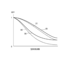
この課題について、具体的に図13を用いて説明する。図13の破線(a)、実線(b)は回復前の2つの色成分のMTFである。破線(c)、実線(d)は、それぞれ(a)、(b)で表された色成分の回復後のMTFである。ウィナーフィルタを用いて回復処理を行うと、回復前の2つの色成分のMTF(a)、(b)の差よりも回復後の2つの色成分のMTF(c)、(d)の差が広がってしまう。回復後の(c)、(d)共に(a)、(b)に比べMTFが向上しているため画像の鮮鋭度は向上している。しかし色付き(色収差)として画像に表れてしまう各色成分間のMTFの差は拡大してしまう。
そこで本発明は、画像の鮮鋭度を向上させつつ、色収差を低減することが可能な画像処理装置を提供することを課題とする。
上記課題を解決するために本発明は、
入力画像を取得する画像取得手段と、
前記入力画像と、被写体像を前記入力画像として形成するために用いた撮像系の伝達関数に基づいた画像回復フィルタを演算することにより、回復画像を生成する画像回復処理手段とを有し、
前記画像回復フィルタは、被写体が白色点光源である場合、前記回復画像における2つの色成分のスペクトルの差が、前記入力画像における該2つの色成分のスペクトルの差よりも減少するように回復することを特徴とする画像処理装置。
入力画像を取得する画像取得手段と、
前記入力画像と、被写体像を前記入力画像として形成するために用いた撮像系の伝達関数に基づいた画像回復フィルタを演算することにより、回復画像を生成する画像回復処理手段とを有し、
前記画像回復フィルタは、被写体が白色点光源である場合、前記回復画像における2つの色成分のスペクトルの差が、前記入力画像における該2つの色成分のスペクトルの差よりも減少するように回復することを特徴とする画像処理装置。
鮮鋭度を向上させつつ、色収差を低減した画像を得ることが可能となる。
まず、具体的な実施例の説明に先立って、各実施例に用いられる画像処理技術について説明する。
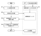
はじめに、本発明の画像処理方法について図1を用いて説明する。まずステップS11の画像取得工程において、入力画像を取得する。次にステップS12において、ステップS11で取得された入力画像の撮像条件を取得する。次にステップ13において、撮像条件に対応する画像回復フィルタをメモリから選択する。予めメモリに用意された撮像条件と異なる場合には、適宜補正して用いることもできる。次にステップS14の画像回復処理工程(補正処理工程)では、ステップS13の画像回復フィルタを用いて画像回復処理(補正処理)を実行する。そしてステップS14で補正された補正画像を出力画像として出力する。ステップ13に用いられる画像回復フィルタは撮像光学系(撮像系)の光学伝達関数(OTF)と色収差補正係数に基づいて生成される。
尚、図1の処理の前後、あるいは途中に例えば倍率色収差補正、歪曲収差補正、周辺光量補正などの電子収差補正やデモザイキング、ガンマ変換、画像圧縮などの処理を挿入しても良い。次に、図1に示した各処理についてより詳細に説明する。
尚、MTFは撮像系の伝達関数(撮像光学系の光学伝達関数)の絶対値(振幅成分)であるが、被写体が白色点光源の場合は、MTFは画像のスペクトルとして捉えることもできる。
(画像取得工程)
画像取得工程により取得される画像(以下、入力画像)は、撮像光学系を介して撮像素子で撮像することで得られたデジタル画像であり、レンズと各種の光学フィルタ類を含む撮像系の収差による光学伝達関数(OTF)により劣化している。撮像光学系はレンズの他にも曲率を有するミラー(反射面)を用いることもできる。
画像取得工程により取得される画像(以下、入力画像)は、撮像光学系を介して撮像素子で撮像することで得られたデジタル画像であり、レンズと各種の光学フィルタ類を含む撮像系の収差による光学伝達関数(OTF)により劣化している。撮像光学系はレンズの他にも曲率を有するミラー(反射面)を用いることもできる。
また、入力画像は色空間により表される。色空間の表し方には、例えばRGBがあるが、RGB以外にもLCHで表現される明度、色相、彩度や、YCbCrで表現される輝度、色差信号などがある。その他の色空間として、XYZ、Lab、Yuv、JChや色温度がある。これら一般に用いられている色空間により表される値を、色成分として本発明を適用することができる。
また、入力画像は各画素に一つの色成分の信号値を有するモザイク画像でも良いし、このモザイク画像を色補間処理(デモザイキング処理)して各画素に複数の色成分の信号値を有したデモザイク画像でも良い。モザイク画像は色補間処理(デモザイキング処理)やガンマ変換やJPEG等の画像圧縮などの画像処理を行う前の画像として、RAW画像とも呼ぶ。例えば単板の撮像素子で複数の色成分の情報を得る場合には、各画素に分光透過率の異なるカラーフィルタを配置して、各画素に一つの色成分の信号値を有するモザイク画像を取得する。このモザイク画像に色補間処理を行うことで各画素に複数の色成分の信号値を有した画像を取得することができる。また、多板、例えば3板の撮像素子を用いる場合には各撮像素子ごとに分光透過率の異なるカラーフィルタを配置して、撮像素子ごとに異なる色成分の画像信号値を有したデモザイク画像を取得することになる。この場合、各撮像素子間で、対応する画素に対してそれぞれの色成分の信号値を有しているので、特に色補間処理を行わなくとも各画素に複数の色成分の信号値を有した画像を取得することができる。
また入力画像には、入力画像を補正するための各種の補正情報を付帯することができる。該補正情報には、レンズの焦点距離(ズーム位置)、絞り値、撮影距離(合焦距離)、露光時間、ISO感度などの撮像条件に関する情報(撮像条件情報)が含まれる。撮像から画像の出力までの一連の処理を一つの撮像装置で行う場合には、入力画像に撮像条件情報や補正情報を付帯しなくとも装置内で取得することもできる。しかし、撮像装置からRAW画像を取得し、撮像装置とは別体の画像処理装置で画像回復処理や現像処理等を行う場合には、上記のように画像に撮像条件情報や補正情報を付帯することが好ましい。ただしこれに限られず、画像処理装置に予め補正情報を記憶させ、入力画像に付帯された撮像条件情報から補正情報を選択可能なシステムを構成すれば、必ずしも画像に補正情報を付帯する必要はない。
尚、入力画像は撮像光学系を介して撮像素子で撮像することで得られたデジタル画像と記述したが、入力画像は撮像光学系を含まない撮像系により得られたデジタル画像でも良い。例えば、被写体面に撮像素子を密着させて撮像を行うスキャナ(読み取り装置)やX線撮像装置はレンズのような撮像光学系を持たない撮像装置により得られた画像であってもよい。これら、撮像光学系を持たないが、撮像素子による画像サンプリングによって生成された画像は少なからず劣化する。この場合の劣化特性は、撮像光学系の光学伝達関数(狭義の光学伝達関数)によるものではないが、撮像系のシステム伝達関数によるものであり、このシステム伝達関数は光学伝達関数に相当するものと言える。このため、本発明の実施例にいう「光学伝達関数」は、このような撮像光学系を含まない撮像系のシステム伝達関数を含む広義の光学伝達関数である。
(画像回復フィルタ生成工程)
次に、画像回復フィルタの生成について図2(A)、(B)を参照しながら説明する。図2(A)は実空間において入力画像の画素に対してコンボリューション処理が行われる画像回復フィルタの模式図である。画像回復フィルタのタップ(セル)数は、撮像系の収差特性や要求される回復精度に応じて決めることができ、画像が2次元のときは、一般的に画像の各画素に対応したタップ数を有する2次元の画像回復フィルタとなる。図2(A)には、例として11×11タップの2次元画像回復フィルタを示した。また、画像回復フィルタのタップ数に関しては、一般的に多いほど回復精度が向上するので、タップ数は要求画質、画像処理能力、収差の特性等に応じて設定される。
次に、画像回復フィルタの生成について図2(A)、(B)を参照しながら説明する。図2(A)は実空間において入力画像の画素に対してコンボリューション処理が行われる画像回復フィルタの模式図である。画像回復フィルタのタップ(セル)数は、撮像系の収差特性や要求される回復精度に応じて決めることができ、画像が2次元のときは、一般的に画像の各画素に対応したタップ数を有する2次元の画像回復フィルタとなる。図2(A)には、例として11×11タップの2次元画像回復フィルタを示した。また、画像回復フィルタのタップ数に関しては、一般的に多いほど回復精度が向上するので、タップ数は要求画質、画像処理能力、収差の特性等に応じて設定される。
図2(A)では各タップ内の値を省略しているが、この画像回復フィルタの1断面を図2(B)に示す。この画像回復フィルタの各タップのもつ値(係数値)の分布が、コンボリューション処理の際に、収差によって空間的に広がった信号値を理想的には元の1点に戻す役割を果たしている。
この画像回復フィルタを生成するためには、まず、撮像系の光学伝達関数(OTF)を計算若しくは計測する。劣化画像が撮像光学系を持たない撮像系により得られた画像である場合には、光学伝達関数としてシステムの伝達関数を用いればよい。
そして上記OTF取得後、そのOTFの逆数に基づいた関数を逆フーリエ変換することにより画像回復フィルタが生成される。尚、OTFの逆数は逆フィルタと呼ばれる。
被写体として点光源を仮定した場合は、撮像系を介して取得された画像の周波数特性は光学伝達関数(OTF)そのものとなる。従って、入力画像(劣化画像)の周波数特性(OTF)に、画像回復フィルタの周波数特性を掛け合わせれば、回復画像の周波数特性を知ることができる。
よって式5における回復画像の周波数特性は[rOTF]の部分である。

ここで、M(u,v)は画像回復フィルタの周波数特性、H(u,v)は入力画像(劣化画像)の周波数特性(OTF)であり、[rOTF]は白色点光源を撮影した画像の回復後の周波数特性である。つまり、画像回復フィルタは撮像系の2つの色成分の伝達関数(1/H(u,v))と、該2つの色成分のMTF(OTFの絶対値)の差が減少するように補正した補正伝達関数と([rOTF])に基づいて生成される。
言い換えれば、本実施例の画像回復フィルタは被写体から前記第1回復画像を得る際の2つの色成分の伝達関数の絶対値の差が、撮像系の2つの色成分の伝達関数の絶対値の差よりも小さくなるように構成される。
式5の[rOTF]の部分を色成分間の差が減少するようにした画像回復フィルタは、色収差補正機能を有する。
また、回復画像の位相劣化は零であることが望ましいので、rOTFは位相成分を持たないようにすれば更によい。つまり、rOTFは実数部のみを有する関数とし、実質的にはMTFと等しくなるようにする。ただし、rOTFには許容可能な範囲で、虚数部に値を持たせてもよい。
式5に示した画像回復フィルタを用いれば、点光源に限らず、どのような被写体でも、あたかも光学伝達関数(OTF)がrOTFの特性(点光源を撮影した画像の回復後の周波数特性)を持った撮像系を介して取得することができる。
また、色成分間で共通のOTF(rH(u,v))を用いることで、あたかも色成分間にMTFの差が無い撮像系で撮影したような画像を得ることができる。
式6に、色収差補正機能を有する、より具体的な画像回復フィルタの一例を示す。

式6で示した色収差補正の機能を有する画像回復フィルタM(u,v)は、右辺の|rH(u,v)|がOTFの絶対値(MTF)であるため、回復度合いを決定するパラメータSNRの値に限らず位相成分は消滅する。PSFは対称な形状に補正することができ、さらに画像の先鋭度も向上させることができる。
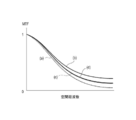
式6で示した画像回復フィルタの機能について、図3を用いて説明する。図3の破線(a)、実線(b)はそれぞれ第1色成分、第2色成分に対応する回復前のMTFを、破線(c)、実線(d)はそれぞれ第1色成分、第2色成分に対応する回復後のMTFを表している。回復前の画像のMTFは図3(a)、(b)のように色成分ごとに異なっているが、回復後のMTFは(c)、(d)のように色成分間で揃っている(差が減少している)。
言い換えれば、本実施例の画像処理方法に用いる画像回復フィルタは、被写体が白色点光源の場合、回復画像における2つの色成分のスペクトルの差が、入力画像における該2つの色成分のスペクトルの差よりも減少するように回復する。この画像回復フィルタを用いることにより画像の色収差を低減しつつ、鮮鋭度を向上させる(回復する)ことができる。ここで、スペクトルの差とはスペクトルの周波数平均の差である。
また、式6では色成分間で共通なrH(u、v)を用いたが、各色成分の回復後のMTFの差が、回復前のMTFの差よりも低減するように各色成分の画像回復フィルタのrH(u、v)を設定することで、色収差の補正量を制御することができる。式7にその方法を表した式を示す。

式7は色収差補正係数Cnm(n、m=1、2、3)を用いたrH(u、v)の補正方法であり、付帯記号R、G、Bは各色成分を示している。式8から式10に色収差補正係数の例を示す。

式8の場合、rH(u、v)R、rH(u、v)G、rH(u、v)Bは各色成分のMTFの平均値が共通の画像回復フィルタ生成に用いる値になる。
式9の場合、rH(u、v)R、rH(u、v)G、rH(u、v)BともにG成分を50%の割合で、R成分およびB成分を25%ずつの割合で合成(合算)した値が、共通の画像回復フィルタ生成に用いる値になる。
式10の場合、自分の色成分を50%の割合で、残りの2つの色成分を25%ずつの割合で合成(合算)した値が、各色成分ごとの画像回復フィルタが生成に用いる値になる。式10は各色成分ごとにrH(u、v)の値は異なっているが、他の色成分と混合させているため色収差を低減させることができる。
式10に挙げたような、rH(u、v)R、rH(u、v)G、rH(u、v)Bがそれぞれ異なっている場合の、回復前と回復後のMTFの変化を図4に示す。図4の破線(a)、実線(b)はそれぞれ第1色成分、第2色成分の回復前のMTF、破線(c)、実線(d)はそれぞれ第1色成分、第2色成分の回復後のMTFを表している。図3の実線(c)、破線(d)のように一致しなくとも、回復前の図4の破線(a)、実線(b)に対して色成分間のMTF差が低減し、色収差を低減することができる。より好ましくは、第1色成分と第2色成分の、回復前のMTFの差の周波数平均に対して、回復後のMTFの差の周波数平均が、1/2以下となるように補正する。図4の場合、(a)と(b)の差の周波数平均に対して、(c)と(d)の差の周波数平均を1/2とすることが好ましい。周波数平均を計算する周波数の範囲は、センサのナイキスト周波数の範囲とする。
つまり、画像回復フィルタを用いて撮像系の2つの色成分のMTFの差を減少させるように回復することにより、色収差を低減することができ、良質な画像を得ることができる。
その他、入力画像がRGBの色成分からなる場合、比視感度の高い色成分(例えば、GあるいはR)のMTFとその他の色成分(例えば、B)のMTFの差を減少させる画像回復フィルタとすることにより、視覚的な色付きを低減することができる。
尚、式6で示した画像回復フィルタのH(u、v)の部分が色成分ごとに異なるため、rH(u、v)が色成分間で共通であっても色成分ごとに特性の異なる画像回復フィルタとなる。
尚、光学伝達関数(OTF)は撮像系のみならず、撮像の過程で光学伝達関数(OTF)を劣化させる要因を含めることができる。例えば、複屈折を有する光学ローパスフィルタは光学伝達関数(OTF)の周波数特性に対して高周波成分を抑制するものである。また、撮像素子の画素開口の形状や開口率も周波数特性に影響している。他にも光源の分光特性や各種波長フィルタの分光特性がある。これらを含めた広義の光学伝達関数(OTF)に基づいて、画像回復フィルタを作成することが望ましい。
本発明の画像回復フィルタは式5以外の変形も可能である。式5の右辺は、1/H(u、v)と、rOTFから成っており、rOTFの部分を色成分間で共通にすればよい。
(画像回復処理工程(補正工程))
次に、生成した画像回復フィルタを用いて、補正画像を得る方法について説明する。
次に、生成した画像回復フィルタを用いて、補正画像を得る方法について説明する。
既に説明しているが、補正工程においては劣化画像に画像回復フィルタをコンボリューションすることにより、補正画像(回復画像)を得ることができる。ここでは、画像回復フィルタのタップ内に含まれる各画素に対してコンボリューション(畳み込み積分、積和)処理が行われる。コンボリューションは、ある画素の信号値を改善するために、その画素を画像回復フィルタの中心と一致させる。そして、画像と画像回復フィルタの対応画素ごとに画像の信号値と画像回復フィルタの係数値の積をとり、その総和を中心画素の信号値として置き換える処理である。
入力画像に対して画像回復フィルタを作用させたり、コンボリューション処理を行ったりすることの利点は、画像回復処理で画像のフーリエ変換や逆フーリエ変換を行うことなく画像を回復することができる。一般的にコンボリューション処理の負荷は、フーリエ変換を行う負荷に比べると小さい。したがって、画像回復処理を行うにあたって、処理負担を軽減することができる。
尚、画像回復フィルタの縦横のタップ数について既に述べたが、縦横のタップ数が必ずしも同じである必要はなく、コンボリューションの処理を行う際に考慮するようにすれば任意に変更することができる。
その他、本発明の画像回復処理は、画像の劣化過程が線形である方が劣化前の元画像に回復するための逆過程を高精度に処理できるため、入力画像は諸々の適応的な非線形処理が行われていないことが好ましい。つまり、モザイク画像(RAW画像)に対して行うことがより好ましい。しかし、入力画像がモザイク画像であってもデモザイク画像であっても本発明の画像回復処理を適用することができる。理由は、色補間処理による劣化過程が線形であれば、画像回復フィルタの生成において、この劣化関数を考慮することで画像回復処理を行うことができるからである。また、回復の要求精度が低い場合や諸々の画像処理が行われた画像しか入手できない場合には、デモザイク画像に対して画像回復処理を行っても色収差を低減するという効果を得ることができる。
(画像出力工程)
以上の処理により取得した補正画像(回復画像)を、所望のデバイスに出力する。撮像装置であれば表示部あるいは記録媒体等に出力する。画像回復処理を行った画像に対して、その他の画像処理などを行うのであれば、後の工程を実行するデバイスに画像を出力すればよい。
以上の処理により取得した補正画像(回復画像)を、所望のデバイスに出力する。撮像装置であれば表示部あるいは記録媒体等に出力する。画像回復処理を行った画像に対して、その他の画像処理などを行うのであれば、後の工程を実行するデバイスに画像を出力すればよい。
以上、本発明の画像処理について各工程に分けて順に説明してきたが、各工程のうち、いくつかの工程を同時に処理できる場合はまとめて処理することができる。また、各工程の前後に適宜必要な処理工程を追加することも可能である。さらに、説明に用いた式や等号記号は本発明の画像処理の具体的なアルゴリズムをこれに限定するものではなく、目的を達成しうる範囲で必要に応じた変形が可能である。
以下、上述した画像処理を適用した実施例について図面を用いて説明する。
図5は実施例1における撮像装置の構成概略図である。不図示の被写体像を撮像光学系101で撮像素子102に結像する。撮像素子102は、結像した光を電気信号に変換(光電変換)し、該電気信号をA/Dコンバータ103がデジタル信号に変換する。そして画像処理部104は、該デジタル信号(入力画像)に対して所定の処理と併せて画像処理を行う。ここでの所定の処理とは、例えば、倍率色収差補正、歪曲収差補正、周辺光量補正などの電子収差補正やデモザイキング、ガンマ変換、画像圧縮などの処理である。
まず、状態検知部107から撮像装置の撮像状態情報を得る。状態検知部107はシステムコントローラ110から直接、撮像状態の情報を得ても良いし、例えば撮像光学系101に関する撮像状態情報は撮像系制御部106から得ることもできる。次に撮像状態に応じた画像回復フィルタを記憶部108から選択し、画像処理部104に入力された画像に対して画像回復処理を行う。画像回復フィルタは撮像状態に応じて記憶部108から選択したものをそのまま用いても良いし、予め用意した画像回復フィルタを補正して、より撮像状態に適した画像回復フィルタに補正したものを用いることもできる。
そして、画像処理部104で処理した出力画像を画像記録媒体109に所定のフォーマットで保存する。この出力画像は色収差が補正され先鋭度が向上した画像である。また、表示部105には、画像回復処理後の画像に表示のための所定の処理を行った画像を表示しても良いし、高速表示のために補正処理を行わない、又は簡易的な補正処理を行った画像を表示しても良い。
上述した一連の制御はシステムコントローラ110で行われ、撮像系の機械的な駆動はシステムコントローラ110の指示により撮像系制御部106で行う。絞り101aは、Fナンバーの撮影状態設定として開口径が制御される。フォーカスレンズ101bは、撮影距離に応じてピント調整を行うために不図示のオートフォーカス(AF)機構や手動のマニュアルフォーカス機構によりレンズの位置が制御される。
この撮像系にはローパスフィルタや赤外線カットフィルタ等の光学素子を入れても構わない。ローパスフィルタ等の光学伝達関数(OTF)の特性に影響を与える素子を用いる場合には画像回復フィルタを作成する時点でこの素子の影響を考慮すれば、より高精度に回復処理を行うことが可能である。赤外カットフィルタにおいても、分光波長の点像分布関数(PSF)の積分値であるRGBチャンネルの各PSF、特にRチャンネルのPSFに影響するため、画像回復フィルタを作成する時点で考慮するとより好ましい。
また、撮像光学系101は撮像装置の一部として構成されているが、一眼レフカメラにあるような交換式のものであっても良い。絞りの開口径制御やマニュアルフォーカスなどの機能は撮像装置の目的に応じて用いなくても良い。
また、光学伝達関数(OTF)は1つの撮影状態においても撮像系の像高(画像の位置)に応じて変化するので、本発明の画像回復処理を像高に応じて変更して行うことが望ましい。
また、画像処理部104は少なくとも演算部と一時的記憶部(バッファー)を有する。上記の画像処理の各工程ごとに必要に応じて一時的に記憶部に対して画像の書き込み(記憶)および読み出しを行う。また、一時的に記憶するための記憶部は前記一時的記憶部(バッファー)に限定せず、記憶部108でも良く、記憶機能を有する記憶部のデータ容量や通信速度に応じて好適なものを適宜選択して用いることができる。その他、記憶部108には色収差補正係数、画像回復フィルタ、補正情報などのデータが記憶されている。
図6を用いて、画像回復フィルタの選択と補正について説明する。図6には、撮像状態情報と該撮像状態情報に基づいて記憶部108に格納された複数の画像回復フィルタ(黒丸)を模式的に示す。記憶部108に格納された画像回復フィルタは、焦点位置(状態A)、絞り値(状態B)および被写体距離(状態C)の3つの撮像状態を軸とした撮像状態空間中に離散的に配置されている。撮像状態空間中の各点(黒丸)の座標が、記憶部108に記憶されている画像回復フィルタを示す。尚、図6では、画像回復フィルタを各各撮像状態に対して直交した線上の格子点に配置しているが、画像回復フィルタを格子点から外して配置しても構わない。また、撮像状態の種類は、焦点距離、絞り値および被写体距離に限らず、その数も3つでなくてもよく、4つ以上の撮像状態による4次元以上の撮像状態空間を構成して、その中に画像回復フィルタを離散的に配置してもよい。
図6において、大きな白丸で示した撮像状態が、状態検知部107により検知された実際の撮像状態であるとする。実際の撮像状態位置に対応する位置、またはその近傍に予め格納された画像回復フィルタが存在する場合には、その画像回復フィルタを選択して画像回復処理に用いることができる。実際の撮像状態に対応する位置の近傍の画像回復フィルタを選択する際の1つの方法は、実際の撮像状態と画像回復フィルタが格納された複数の撮像状態との間の撮像状態空間で距離(撮像状態の相違量)を算出する。そして、最も距離の短い位置の画像回復フィルタを選択する方法である。この方法により、図6に小さな白丸で示した位置の画像回復フィルタが選択される。
また、他の方法として、画像回復フィルタ選択に撮像状態空間中の方向による重み付けをする方法がある。すなわち、撮像状態空間中の距離と重み付けした方向の積を評価関数として、該評価関数の値が最も高い画像回復フィルタを選択する方法である。
次に、選択された画像回復フィルタを補正することで、新たな画像回復フィルタを生成する方法について説明する。画像回復フィルタを補正するにあたり、まず実際の撮像状態と画像回復フィルタが格納された撮像状態との間の撮像状態空間での距離(状態相違量)を算出し、最も距離の短い(状態相違量が最も小さい)位置の画像回復フィルタを選択する。状態相違量が最も小さい画像回復フィルタを選択することで、画像回復フィルタの補正量も少なくすることができ、撮像状態での本来の画像回復フィルタに近い画像回復フィルタを生成することができる。
図6では、小さな白丸で示した位置の画像回復フィルタが選択される。この選択された画像回復フィルタに対応する撮像状態と、実際の撮像状態との状態相違量ΔA、ΔB、ΔCを算出する。この状態相違量に基づいて状態補正係数を算出し、該状態補正係数を用いて選択された画像回復フィルタを補正する。これにより、実際の撮像状態に対応した画像回復フィルタを生成することができる。
また、他の方法として、実際の撮像状態の近傍に位置する複数の画像回復フィルタを選択し、該複数の画像回復フィルタと実際の撮像状態との状態相違量に応じて補間処理することで、撮像状態に適した画像回復フィルタを生成することができる。ここでの補間処理は、2次元の画像回復フィルタ同士の対応タップの係数値を線形補間、多項式補間およびスプライン補間等等を用いて補間すれば良い。
また、画像回復フィルタの生成に用いる光学伝達関数(OTF)は、光学設計ツールや光学解析ツールを用いて計算により求めることができる。さらに、撮像光学系単体や撮像装置の実際の状態における光学伝達関数(OTF)を、計測して求めることもできる。
図7に画像処理部104で実行される本実施例の画像回復処理の具体的なフローチャートを示す。図中の●印は画像等の画素データを少なくとも一時的に記憶するステップを表す。
画像処理部104は画像取得工程で入力画像を取得する。次に状態検知部107から撮像状態情報を得る(ステップS72)。そして、記憶部108から撮像状態に応じた画像回復フィルタを選択し(ステップS73)、画像回復処理工程(補正工程)でこの画像回復フィルタを用いて入力画像に対して回復処理を行う(ステップS74)。
次に画像形成に必要なその他の処理を行い回復された画像を出力する(ステップS76)。ここでのその他の処理としては、前記の補正画像がモザイク画像の状態であれば、色補間処理(デモザイキング処理)、シェーディング補正(周辺光量補正)、歪曲収差補正などがある。また、ここで説明したその他の処理を含めた諸々の画像処理は、上記フローの前後や中間に必要に応じて挿入することもできる。
ここで、画像回復処理の流れとしてより好ましい例について図8を用いて説明する。図8は、回復処理を行う前と後のMTFの変化を表す。破線(a)、実線(b)はそれぞれ画像回復処理を行う前の第1色成分、第2色成分のMTFであり、破線(c)、実線(d)は回復処理を行った後の第1色成分、第2色成分のMTFである。図8に示すように、回復前の2つの色成分のMTF(a)、(b)に対して、画像回復処理を図3、図4で示した回復度合いよりも低い回復度合いで行う。これにより、(c)、(d)のように、MTFはあまり向上されない(MTFは低い)状態で、色収差が補正された状態になる。
この状態は、収差の位相成分および色収差は補正されているが、先鋭度は低い状態である。このような回復処理を行った回復画像に対してエッジ強調処理を行うことで、エッジ部のみの先鋭度を向上することができるので、画像全体に対して回復処理を行うよりも、ノイズ増幅を抑制することができる。
つまり、回復度合いが低い(MTFの回復量が小さい)回復画像に、エッジ強調処理を行うことにより、色収差を低減しつつ、ノイズの増幅を抑制した画像を得ることができる。
さらに好ましくは、ナイキスト周波数内において、画像回復処理において各色成分の回復後のMTFの周波数平均が、回復前の最大のMTFの1.5倍以下とすることが好ましい。
以上の処理により、ノイズ増幅を抑制しつつ、色収差が低減された良質な画像を得ることができる。
その他に、位相や色収差が補正された画像に対してエッジ強調処理を行うことにより、従来の位相や色収差が補正されていない画像に対してエッジ強調処理を行うよりも対称性が高く色付きの無い高画質な画像を得ることができる。
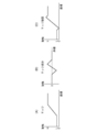
エッジ強調処理については図9を用いて説明する。エッジ強調フィルタの一例を図9に示す。エッジ強調を行うためのフィルタは、図9に示すように、入力画像をそのまま出力するフィルタと微分フィルタの差分によって生成することができる。微分フィルタは1次微分を行うソーベルフィルタや2次微分を行うラプラシアンフィルタなどがよく知られている。図9の微分フィルタはラプラシアンフィルタである。エッジ強調フィルタは隣接画素との画素値の関係により処理を行うため、図のようにタップ数が3×3程度のフィルタがよく用いられている。
図10に図9に示したエッジ強調フィルタを用いた場合のエッジ部分の強調効果を示す。図10(A)、(B)、(C)は画像中のエッジ部の輝度をある断面で見たとき図である。横軸は座標、縦軸は振幅を表している。図10の(A)は、画像中のエッジ部分の輝度断面であり、これに微分フィルタでエッジ部を抽出して符号反転したものが(B)である。元の画像(A)に(B)を足し合わせることで(C)のように、エッジの傾きを急峻に強調することができる。エッジ強調処理は特にエッジの急峻な部分にのみ作用し、先鋭化するので画像全体に対してはノイズ増幅の影響が少ないという利点やフィルタのタップ数が比較的小さいため高速な処理が可能であるという利点がある。よって、低い回復度合いの画像回復処理を行った後に、エッジ強調処理をするのがより好ましい。このようにエッジ強調処理と組み合わせる場合には、図7のその他必要な処理にエッジ強調処理を含めれば良い。画像のエッジ部が強調処理が可能なその他の処理としては、シャープネス処理等が挙げられる。
以上、各処理工程の好ましい前後関係や考慮すべき処理について説明したが、処理工程の順序に対して別の観点での制約がある場合にはこれに限るものではなく、処理上の制約条件や要求画質に応じて変更しても構わない。また、撮像装置に関する実施例を示したが、その要旨の範囲内で種々の変形及び変更が可能である。
図11(A)には、本発明の実施例2である画像処理システムの構成図を示した。画像処理装置111は、情報処理装置により構成され、実施例1にて説明した画像処理方法を該情報処理装置に実行させるための画像処理ソフトウェア(画像処理プログラム)112を搭載している。
撮像装置113は、カメラ、顕微鏡、内視鏡、スキャナ等を含む。記憶媒体114は、半導体メモリ、ハードディスク、ネットワーク上のサーバー等、撮像により生成された画像(撮影画像データ)を記憶する。
画像処理装置111は、撮像装置113または記憶媒体114から画像データを取得して、所定の画像処理を行った出力画像(補正画像)データを出力機器116、撮像装置113および記憶媒体114の少なくとも1つに出力する。また、出力先を画像処理装置111に内蔵された記憶部にし、該記憶部に出力画像データを保存しておくこともできる。出力機器116としては、プリンタ等が挙げられる。画像処理装置111には、モニタである表示機器115が接続されており、ユーザはこの表示機器115を通して画像処理作業を行うとともに、回復調整画像(出力画像)を評価することができる。画像処理ソフトウェア112は、画像回復処理機能および回復度合い調整機能の他に、必要に応じて現像機能やその他の画像処理機能を有している。
また、図11(B)には、別の画像処理システムの構成を示している。実施例1のように、撮像装置118単体で実施例1の画像処理を行う場合は、撮像装置118から直接、出力機器119に回復調整画像を出力することができる。
また、出力機器119に、実施例1の画像処理方法を実行する画像処理装置を搭載することで、出力機器119で画像の特徴量に応じて調整係数を設定し、回復度合いの調整を行うことも可能である。さらに、出力機器119の出力画像の劣化特性に応じて回復度合いを調整することで、より高画質な画像を提供することができる。
ここで、画像回復処理および回復度合いの調整を含む画像処理を行うための補正情報の内容と、その受渡しについて説明する。図12に補正情報の一例を示し、この複数の補正情報を補正情報セットと記す。各補正情報について以下に説明する。
「補正制御情報」
補正制御情報は、撮像装置113、画像処理装置111および出力機器116のどれでで回復処理および回復度合い調整処理を行うかを示す設定情報と、該設定情報に応じて他の機器に伝送するデータを選択するための選択情報である。例えば、撮像装置113で回復処理のみ行い、画像処理装置111で回復度合いの調整を行う場合、画像回復フィルタを画像処理装置111に伝送する必要は無いが、少なくとも撮影画像と回復画像あるいは回復成分情報(差分情報)を伝送する必要がある。
補正制御情報は、撮像装置113、画像処理装置111および出力機器116のどれでで回復処理および回復度合い調整処理を行うかを示す設定情報と、該設定情報に応じて他の機器に伝送するデータを選択するための選択情報である。例えば、撮像装置113で回復処理のみ行い、画像処理装置111で回復度合いの調整を行う場合、画像回復フィルタを画像処理装置111に伝送する必要は無いが、少なくとも撮影画像と回復画像あるいは回復成分情報(差分情報)を伝送する必要がある。
「撮像装置情報」
撮像装置情報は、製品名称に相当する撮像装置113の識別情報である。レンズとカメラ本体が交換可能な場合はその組み合わせを含む識別情報である。
撮像装置情報は、製品名称に相当する撮像装置113の識別情報である。レンズとカメラ本体が交換可能な場合はその組み合わせを含む識別情報である。
「撮像状態情報」
撮像状態情報は、撮影時の撮像装置113の状態に関する情報である。例えば、焦点距離(ズーム位置)、絞り値、被写体距離(合焦距離)、ISO感度、ホワイトバランス設定等等である。
撮像状態情報は、撮影時の撮像装置113の状態に関する情報である。例えば、焦点距離(ズーム位置)、絞り値、被写体距離(合焦距離)、ISO感度、ホワイトバランス設定等等である。
「撮像装置個別情報」
撮像装置個別情報は、上記の撮像装置情報に対して、個々の撮像装置の識別情報である。製造誤差のばらつきにより撮像装置の光学伝達関数(OTF)は個体ばらつきがあるため、撮像装置個別情報は個々に最適な回復度合い調整パラメータを設定するために有効な情報である。回復度合い調整パラメータとは、回復強度調整係数μや色合成比調整係数ωである。
撮像装置個別情報は、上記の撮像装置情報に対して、個々の撮像装置の識別情報である。製造誤差のばらつきにより撮像装置の光学伝達関数(OTF)は個体ばらつきがあるため、撮像装置個別情報は個々に最適な回復度合い調整パラメータを設定するために有効な情報である。回復度合い調整パラメータとは、回復強度調整係数μや色合成比調整係数ωである。
「画像回復フィルタ群」
画像回復フィルタ群は、画像回復処理で用いる画像回復フィルタのセットである。画像回復処理を行う装置が画像回復フィルタを有していない場合、別の装置(機器)から画像回復フィルタを伝送する必要がある。
画像回復フィルタ群は、画像回復処理で用いる画像回復フィルタのセットである。画像回復処理を行う装置が画像回復フィルタを有していない場合、別の装置(機器)から画像回復フィルタを伝送する必要がある。
「色収差補正係数」
色収差補正係数は、式2で説明したように、色成分ごとのrH(u,v)を生成するためのH(u,v)の色成分間の混合比に関する係数である。色収差補正係数を決定した機器(装置)と画像回復処理を行う機器(装置)が別の場合には、色収差補正係数を機器間で伝送する。
色収差補正係数は、式2で説明したように、色成分ごとのrH(u,v)を生成するためのH(u,v)の色成分間の混合比に関する係数である。色収差補正係数を決定した機器(装置)と画像回復処理を行う機器(装置)が別の場合には、色収差補正係数を機器間で伝送する。
「ユーザ設定情報」
ユーザ設定情報は、ユーザの好みに応じた回復度合いに調整するための調整パラメータまたは調整パラメータの補正関数である。ユーザは調整パラメータを可変に設定可能であるが、ユーザ設定情報を用いれば、常に初期値として好みの出力画像を得ることができる。また、ユーザ設定情報は、ユーザが調整パラメータを決定した履歴から、最も好む鮮鋭度を学習機能により更新することが好ましい。
ユーザ設定情報は、ユーザの好みに応じた回復度合いに調整するための調整パラメータまたは調整パラメータの補正関数である。ユーザは調整パラメータを可変に設定可能であるが、ユーザ設定情報を用いれば、常に初期値として好みの出力画像を得ることができる。また、ユーザ設定情報は、ユーザが調整パラメータを決定した履歴から、最も好む鮮鋭度を学習機能により更新することが好ましい。
さらに、撮像装置の提供者(メーカー)がいくつかの鮮鋭度パターンに応じたプリセット値をネットワークを介して提供することもできる。
上記の補正情報セットは、個々の画像データに付帯させることが好ましい。必要な補正情報を画像データに付帯させることで、実施例2の画像処理装置を搭載した機器であれば補正処理を行うことができる。また、補正情報セットの内容は必要に応じて、自動および手動で取捨選択可能である。
本発明は上記実施の形態に制限されるものではなく、本発明の精神及び範囲から離脱することなく、様々な変更及び変形が可能である。従って、本発明の範囲を公にするために以下の請求項を添付する。
101 撮像光学系
102 撮像素子
104 画像処理部
106 撮像系制御部
108 記憶部
110 システムコントローラ
102 撮像素子
104 画像処理部
106 撮像系制御部
108 記憶部
110 システムコントローラ
Claims (7)
- 入力画像を取得する画像取得手段と、
前記入力画像と、被写体像を前記入力画像として形成するために用いた撮像系の伝達関数に基づいた画像回復フィルタを演算することにより、回復画像を生成する画像回復処理手段とを有し、
前記画像回復フィルタは、被写体が白色点光源である場合、前記回復画像における2つの色成分のスペクトルの差が、前記入力画像における該2つの色成分のスペクトルの差よりも減少するように回復することを特徴とする画像処理装置。 - 前記画像回復処理手段は、前記入力画像の画素に対して前記画像回復フィルタを畳み込み積分することにより画像回復を行うことを特徴とする請求項1に記載の画像処理装置。
- 被写体像を入力画像として取得する撮像系と、
前記入力画像と前記撮像系の伝達関数に基づいた画像回復フィルタを演算することにより回復画像を生成する画像回復処理手段とを有し、
前記画像回復フィルタは、被写体が白色点光源である場合、前記回復画像における2つの色成分のスペクトルの差が、前記入力画像における該2つの色成分のスペクトルの差よりも減少するように回復することを特徴とする撮像装置。 - 被写体像を入力画像として取得する撮像系の伝達関数に基づいた画像回復フィルタと、該入力画像を演算することにより回復画像を生成する画像回復処理工程を情報処理装置に実行させる画像処理プログラムであって、
前記画像回復フィルタは、被写体が白色点光源である場合、前記回復画像における2つの色成分のスペクトルの差が、前記入力画像における該2つの色成分のスペクトルの差よりも減少するように回復することを特徴とする画像処理プログラム。 - 入力画像を取得する工程と、
前記入力画像と、該入力画像を取得するために用いた撮像系の伝達関数に基づいた画像回復フィルタを演算することにより、回復画像を生成する工程とを有し、
前記画像回復フィルタは、被写体が白色点光源である場合、前記回復画像における2つの色成分のスペクトルの差が、前記入力画像における該2つの色成分のスペクトルの差よりも減少するように回復することを特徴とする画像処理方法。 - 入力画像を取得する画像取得手段と、
前記入力画像と、被写体像を前記入力画像として形成するために用いた撮像系の伝達関数に基づいた画像回復フィルタを演算することにより、回復画像を生成する画像回復処理手段とを有し、
前記画像回復フィルタは、前記撮像系の2つの色成分の伝達関数の絶対値の差を減少させるように回復する画像回復フィルタであることを特徴とする画像処理装置。 - 入力画像を取得する画像取得手段と、
前記入力画像と、被写体像を前記入力画像として形成するために用いた撮像系の伝達関数に基づいた画像回復フィルタを演算することにより、回復画像を生成する画像回復処理手段とを有し、
前記画像回復フィルタは前記撮像系の伝達関数と、2つの色成分の伝達関数の絶対値の差が減少するように補正した補正伝達関数とに基づいて生成されることを特徴とする画像処理装置。
Priority Applications (5)
| Application Number | Priority Date | Filing Date | Title |
|---|---|---|---|
| PCT/JP2010/055862 WO2011121761A1 (ja) | 2010-03-31 | 2010-03-31 | 画像処理装置、およびそれを用いた撮像装置 |
| CN201180016035.9A CN102844788B (zh) | 2010-03-31 | 2011-03-10 | 图像处理装置及使用该图像处理装置的图像拾取装置 |
| JP2012508185A JP5284537B2 (ja) | 2010-03-31 | 2011-03-10 | 画像処理装置、画像処理方法、画像処理プログラム、およびそれを用いた撮像装置 |
| PCT/JP2011/055608 WO2011122283A1 (ja) | 2010-03-31 | 2011-03-10 | 画像処理装置、およびそれを用いた撮像装置 |
| US13/204,530 US8941762B2 (en) | 2010-03-31 | 2011-08-05 | Image processing apparatus and image pickup apparatus using the same |
Applications Claiming Priority (1)
| Application Number | Priority Date | Filing Date | Title |
|---|---|---|---|
| PCT/JP2010/055862 WO2011121761A1 (ja) | 2010-03-31 | 2010-03-31 | 画像処理装置、およびそれを用いた撮像装置 |
Publications (1)
| Publication Number | Publication Date |
|---|---|
| WO2011121761A1 true WO2011121761A1 (ja) | 2011-10-06 |
Family
ID=44711548
Family Applications (1)
| Application Number | Title | Priority Date | Filing Date |
|---|---|---|---|
| PCT/JP2010/055862 WO2011121761A1 (ja) | 2010-03-31 | 2010-03-31 | 画像処理装置、およびそれを用いた撮像装置 |
Country Status (1)
| Country | Link |
|---|---|
| WO (1) | WO2011121761A1 (ja) |
Cited By (1)
| Publication number | Priority date | Publication date | Assignee | Title |
|---|---|---|---|---|
| US10810714B2 (en) | 2017-08-15 | 2020-10-20 | Canon Kabushiki Kaisha | Image restoration processing utilizing settings for image correction |
Citations (3)
| Publication number | Priority date | Publication date | Assignee | Title |
|---|---|---|---|---|
| JP2007028042A (ja) * | 2005-07-14 | 2007-02-01 | Nikon Corp | 画像処理装置 |
| JP2008042874A (ja) * | 2006-07-14 | 2008-02-21 | Eastman Kodak Co | 画像処理装置、画像復元方法およびプログラム |
| JP2009010944A (ja) * | 2007-05-30 | 2009-01-15 | Fujifilm Corp | 撮像装置、撮像方法、及びプログラム |
-
2010
- 2010-03-31 WO PCT/JP2010/055862 patent/WO2011121761A1/ja active Application Filing
Patent Citations (3)
| Publication number | Priority date | Publication date | Assignee | Title |
|---|---|---|---|---|
| JP2007028042A (ja) * | 2005-07-14 | 2007-02-01 | Nikon Corp | 画像処理装置 |
| JP2008042874A (ja) * | 2006-07-14 | 2008-02-21 | Eastman Kodak Co | 画像処理装置、画像復元方法およびプログラム |
| JP2009010944A (ja) * | 2007-05-30 | 2009-01-15 | Fujifilm Corp | 撮像装置、撮像方法、及びプログラム |
Cited By (1)
| Publication number | Priority date | Publication date | Assignee | Title |
|---|---|---|---|---|
| US10810714B2 (en) | 2017-08-15 | 2020-10-20 | Canon Kabushiki Kaisha | Image restoration processing utilizing settings for image correction |
Similar Documents
| Publication | Publication Date | Title |
|---|---|---|
| JP5284537B2 (ja) | 画像処理装置、画像処理方法、画像処理プログラム、およびそれを用いた撮像装置 | |
| JP5188651B2 (ja) | 画像処理装置、およびそれを用いた撮像装置 | |
| JP5441652B2 (ja) | 画像処理方法、画像処理装置、撮像装置および画像処理プログラム | |
| JP5546229B2 (ja) | 画像処理方法、画像処理装置、撮像装置および画像処理プログラム | |
| JP6525718B2 (ja) | 画像処理装置、その制御方法、および制御プログラム | |
| JP5147994B2 (ja) | 画像処理装置およびそれを用いた撮像装置 | |
| JP5054248B2 (ja) | 画像処理装置、画像処理方法、画像処理プログラム、撮像装置 | |
| KR101536162B1 (ko) | 화상처리장치 및 방법 | |
| JP2011124692A5 (ja) | ||
| JP2011123589A5 (ja) | ||
| JP2012129932A (ja) | 画像処理方法、画像処理プログラム、画像処理装置および撮像装置 | |
| WO2011121763A1 (ja) | 画像処理装置、およびそれを用いた撮像装置 | |
| JP5479187B2 (ja) | 画像処理装置及びそれを用いた撮像装置 | |
| JP5344648B2 (ja) | 画像処理方法、画像処理装置、撮像装置および画像処理プログラム | |
| JP2012156716A (ja) | 画像処理装置、撮像装置、画像処理方法およびプログラム。 | |
| JP6415108B2 (ja) | 画像処理方法、画像処理装置、撮像装置、画像処理プログラム、および、記憶媒体 | |
| JP2012234484A (ja) | 画像処理方法、画像処理装置、撮像装置および画像処理プログラム | |
| JP5425136B2 (ja) | 画像処理方法、画像処理装置、撮像装置および画像処理プログラム | |
| WO2011121761A1 (ja) | 画像処理装置、およびそれを用いた撮像装置 | |
| JP6238673B2 (ja) | 画像処理装置、撮像装置、撮像システム、画像処理方法、画像処理プログラム、および、記憶媒体 | |
| JP2012156714A (ja) | プログラム、画像処理装置、画像処理方法および撮像装置。 | |
| JP2023119413A (ja) | 画像処理装置及び方法、撮像装置、プログラム及び記憶媒体 | |
| JP2017224906A (ja) | 画像処理方法およびそれを用いた撮像装置、画像処理装置、画像処理プログラム |
Legal Events
| Date | Code | Title | Description |
|---|---|---|---|
| 121 | Ep: the epo has been informed by wipo that ep was designated in this application |
Ref document number: 10848939 Country of ref document: EP Kind code of ref document: A1 |
|
| NENP | Non-entry into the national phase |
Ref country code: DE |
|
| 122 | Ep: pct application non-entry in european phase |
Ref document number: 10848939 Country of ref document: EP Kind code of ref document: A1 |
|
| NENP | Non-entry into the national phase |
Ref country code: JP |