WO2011118737A1 - Heat treatment method - Google Patents
Heat treatment method Download PDFInfo
- Publication number
- WO2011118737A1 WO2011118737A1 PCT/JP2011/057249 JP2011057249W WO2011118737A1 WO 2011118737 A1 WO2011118737 A1 WO 2011118737A1 JP 2011057249 W JP2011057249 W JP 2011057249W WO 2011118737 A1 WO2011118737 A1 WO 2011118737A1
- Authority
- WO
- WIPO (PCT)
- Prior art keywords
- cooling
- mist
- workpiece
- temperature
- transformation point
- Prior art date
Links
Images


Classifications
-
- C—CHEMISTRY; METALLURGY
- C21—METALLURGY OF IRON
- C21D—MODIFYING THE PHYSICAL STRUCTURE OF FERROUS METALS; GENERAL DEVICES FOR HEAT TREATMENT OF FERROUS OR NON-FERROUS METALS OR ALLOYS; MAKING METAL MALLEABLE, e.g. BY DECARBURISATION OR TEMPERING
- C21D1/00—General methods or devices for heat treatment, e.g. annealing, hardening, quenching or tempering
- C21D1/62—Quenching devices
- C21D1/667—Quenching devices for spray quenching
-
- C—CHEMISTRY; METALLURGY
- C21—METALLURGY OF IRON
- C21D—MODIFYING THE PHYSICAL STRUCTURE OF FERROUS METALS; GENERAL DEVICES FOR HEAT TREATMENT OF FERROUS OR NON-FERROUS METALS OR ALLOYS; MAKING METAL MALLEABLE, e.g. BY DECARBURISATION OR TEMPERING
- C21D1/00—General methods or devices for heat treatment, e.g. annealing, hardening, quenching or tempering
- C21D1/18—Hardening; Quenching with or without subsequent tempering
- C21D1/19—Hardening; Quenching with or without subsequent tempering by interrupted quenching
- C21D1/20—Isothermal quenching, e.g. bainitic hardening
-
- C—CHEMISTRY; METALLURGY
- C21—METALLURGY OF IRON
- C21D—MODIFYING THE PHYSICAL STRUCTURE OF FERROUS METALS; GENERAL DEVICES FOR HEAT TREATMENT OF FERROUS OR NON-FERROUS METALS OR ALLOYS; MAKING METAL MALLEABLE, e.g. BY DECARBURISATION OR TEMPERING
- C21D1/00—General methods or devices for heat treatment, e.g. annealing, hardening, quenching or tempering
- C21D1/18—Hardening; Quenching with or without subsequent tempering
- C21D1/19—Hardening; Quenching with or without subsequent tempering by interrupted quenching
- C21D1/22—Martempering
-
- C—CHEMISTRY; METALLURGY
- C21—METALLURGY OF IRON
- C21D—MODIFYING THE PHYSICAL STRUCTURE OF FERROUS METALS; GENERAL DEVICES FOR HEAT TREATMENT OF FERROUS OR NON-FERROUS METALS OR ALLOYS; MAKING METAL MALLEABLE, e.g. BY DECARBURISATION OR TEMPERING
- C21D1/00—General methods or devices for heat treatment, e.g. annealing, hardening, quenching or tempering
- C21D1/74—Methods of treatment in inert gas, controlled atmosphere, vacuum or pulverulent material
- C21D1/76—Adjusting the composition of the atmosphere
-
- C—CHEMISTRY; METALLURGY
- C21—METALLURGY OF IRON
- C21D—MODIFYING THE PHYSICAL STRUCTURE OF FERROUS METALS; GENERAL DEVICES FOR HEAT TREATMENT OF FERROUS OR NON-FERROUS METALS OR ALLOYS; MAKING METAL MALLEABLE, e.g. BY DECARBURISATION OR TEMPERING
- C21D1/00—General methods or devices for heat treatment, e.g. annealing, hardening, quenching or tempering
- C21D1/74—Methods of treatment in inert gas, controlled atmosphere, vacuum or pulverulent material
- C21D1/773—Methods of treatment in inert gas, controlled atmosphere, vacuum or pulverulent material under reduced pressure or vacuum
-
- C—CHEMISTRY; METALLURGY
- C21—METALLURGY OF IRON
- C21D—MODIFYING THE PHYSICAL STRUCTURE OF FERROUS METALS; GENERAL DEVICES FOR HEAT TREATMENT OF FERROUS OR NON-FERROUS METALS OR ALLOYS; MAKING METAL MALLEABLE, e.g. BY DECARBURISATION OR TEMPERING
- C21D9/00—Heat treatment, e.g. annealing, hardening, quenching or tempering, adapted for particular articles; Furnaces therefor
- C21D9/0056—Furnaces through which the charge is moved in a horizontal straight path
-
- C—CHEMISTRY; METALLURGY
- C21—METALLURGY OF IRON
- C21D—MODIFYING THE PHYSICAL STRUCTURE OF FERROUS METALS; GENERAL DEVICES FOR HEAT TREATMENT OF FERROUS OR NON-FERROUS METALS OR ALLOYS; MAKING METAL MALLEABLE, e.g. BY DECARBURISATION OR TEMPERING
- C21D9/00—Heat treatment, e.g. annealing, hardening, quenching or tempering, adapted for particular articles; Furnaces therefor
- C21D9/0062—Heat-treating apparatus with a cooling or quenching zone
-
- F—MECHANICAL ENGINEERING; LIGHTING; HEATING; WEAPONS; BLASTING
- F27—FURNACES; KILNS; OVENS; RETORTS
- F27B—FURNACES, KILNS, OVENS, OR RETORTS IN GENERAL; OPEN SINTERING OR LIKE APPARATUS
- F27B9/00—Furnaces through which the charge is moved mechanically, e.g. of tunnel type; Similar furnaces in which the charge moves by gravity
- F27B9/02—Furnaces through which the charge is moved mechanically, e.g. of tunnel type; Similar furnaces in which the charge moves by gravity of multiple-track type; of multiple-chamber type; Combinations of furnaces
-
- F—MECHANICAL ENGINEERING; LIGHTING; HEATING; WEAPONS; BLASTING
- F27—FURNACES; KILNS; OVENS; RETORTS
- F27B—FURNACES, KILNS, OVENS, OR RETORTS IN GENERAL; OPEN SINTERING OR LIKE APPARATUS
- F27B9/00—Furnaces through which the charge is moved mechanically, e.g. of tunnel type; Similar furnaces in which the charge moves by gravity
- F27B9/14—Furnaces through which the charge is moved mechanically, e.g. of tunnel type; Similar furnaces in which the charge moves by gravity characterised by the path of the charge during treatment; characterised by the means by which the charge is moved during treatment
- F27B9/20—Furnaces through which the charge is moved mechanically, e.g. of tunnel type; Similar furnaces in which the charge moves by gravity characterised by the path of the charge during treatment; characterised by the means by which the charge is moved during treatment the charge moving in a substantially straight path tunnel furnace
- F27B9/24—Furnaces through which the charge is moved mechanically, e.g. of tunnel type; Similar furnaces in which the charge moves by gravity characterised by the path of the charge during treatment; characterised by the means by which the charge is moved during treatment the charge moving in a substantially straight path tunnel furnace being carried by a conveyor
- F27B9/2407—Furnaces through which the charge is moved mechanically, e.g. of tunnel type; Similar furnaces in which the charge moves by gravity characterised by the path of the charge during treatment; characterised by the means by which the charge is moved during treatment the charge moving in a substantially straight path tunnel furnace being carried by a conveyor the conveyor being constituted by rollers (roller hearth furnace)
-
- F—MECHANICAL ENGINEERING; LIGHTING; HEATING; WEAPONS; BLASTING
- F27—FURNACES; KILNS; OVENS; RETORTS
- F27B—FURNACES, KILNS, OVENS, OR RETORTS IN GENERAL; OPEN SINTERING OR LIKE APPARATUS
- F27B9/00—Furnaces through which the charge is moved mechanically, e.g. of tunnel type; Similar furnaces in which the charge moves by gravity
- F27B9/14—Furnaces through which the charge is moved mechanically, e.g. of tunnel type; Similar furnaces in which the charge moves by gravity characterised by the path of the charge during treatment; characterised by the means by which the charge is moved during treatment
- F27B9/20—Furnaces through which the charge is moved mechanically, e.g. of tunnel type; Similar furnaces in which the charge moves by gravity characterised by the path of the charge during treatment; characterised by the means by which the charge is moved during treatment the charge moving in a substantially straight path tunnel furnace
- F27B9/26—Furnaces through which the charge is moved mechanically, e.g. of tunnel type; Similar furnaces in which the charge moves by gravity characterised by the path of the charge during treatment; characterised by the means by which the charge is moved during treatment the charge moving in a substantially straight path tunnel furnace on or in trucks, sleds, or containers
-
- F—MECHANICAL ENGINEERING; LIGHTING; HEATING; WEAPONS; BLASTING
- F27—FURNACES; KILNS; OVENS; RETORTS
- F27D—DETAILS OR ACCESSORIES OF FURNACES, KILNS, OVENS, OR RETORTS, IN SO FAR AS THEY ARE OF KINDS OCCURRING IN MORE THAN ONE KIND OF FURNACE
- F27D15/00—Handling or treating discharged material; Supports or receiving chambers therefor
- F27D15/02—Cooling
- F27D15/0206—Cooling with means to convey the charge
-
- F—MECHANICAL ENGINEERING; LIGHTING; HEATING; WEAPONS; BLASTING
- F27—FURNACES; KILNS; OVENS; RETORTS
- F27D—DETAILS OR ACCESSORIES OF FURNACES, KILNS, OVENS, OR RETORTS, IN SO FAR AS THEY ARE OF KINDS OCCURRING IN MORE THAN ONE KIND OF FURNACE
- F27D7/00—Forming, maintaining, or circulating atmospheres in heating chambers
- F27D7/06—Forming or maintaining special atmospheres or vacuum within heating chambers
-
- F—MECHANICAL ENGINEERING; LIGHTING; HEATING; WEAPONS; BLASTING
- F27—FURNACES; KILNS; OVENS; RETORTS
- F27D—DETAILS OR ACCESSORIES OF FURNACES, KILNS, OVENS, OR RETORTS, IN SO FAR AS THEY ARE OF KINDS OCCURRING IN MORE THAN ONE KIND OF FURNACE
- F27D9/00—Cooling of furnaces or of charges therein
-
- C—CHEMISTRY; METALLURGY
- C21—METALLURGY OF IRON
- C21D—MODIFYING THE PHYSICAL STRUCTURE OF FERROUS METALS; GENERAL DEVICES FOR HEAT TREATMENT OF FERROUS OR NON-FERROUS METALS OR ALLOYS; MAKING METAL MALLEABLE, e.g. BY DECARBURISATION OR TEMPERING
- C21D2211/00—Microstructure comprising significant phases
- C21D2211/008—Martensite
-
- C—CHEMISTRY; METALLURGY
- C21—METALLURGY OF IRON
- C21D—MODIFYING THE PHYSICAL STRUCTURE OF FERROUS METALS; GENERAL DEVICES FOR HEAT TREATMENT OF FERROUS OR NON-FERROUS METALS OR ALLOYS; MAKING METAL MALLEABLE, e.g. BY DECARBURISATION OR TEMPERING
- C21D2211/00—Microstructure comprising significant phases
- C21D2211/009—Pearlite
-
- F—MECHANICAL ENGINEERING; LIGHTING; HEATING; WEAPONS; BLASTING
- F27—FURNACES; KILNS; OVENS; RETORTS
- F27D—DETAILS OR ACCESSORIES OF FURNACES, KILNS, OVENS, OR RETORTS, IN SO FAR AS THEY ARE OF KINDS OCCURRING IN MORE THAN ONE KIND OF FURNACE
- F27D9/00—Cooling of furnaces or of charges therein
- F27D2009/0002—Cooling of furnaces
- F27D2009/0005—Cooling of furnaces the cooling medium being a gas
-
- F—MECHANICAL ENGINEERING; LIGHTING; HEATING; WEAPONS; BLASTING
- F27—FURNACES; KILNS; OVENS; RETORTS
- F27D—DETAILS OR ACCESSORIES OF FURNACES, KILNS, OVENS, OR RETORTS, IN SO FAR AS THEY ARE OF KINDS OCCURRING IN MORE THAN ONE KIND OF FURNACE
- F27D9/00—Cooling of furnaces or of charges therein
- F27D2009/007—Cooling of charges therein
- F27D2009/0072—Cooling of charges therein the cooling medium being a gas
- F27D2009/0075—Cooling of charges therein the cooling medium being a gas in direct contact with the charge
Definitions
- the present invention relates to a heat treatment method, and more particularly to a heat treatment method for quenching a workpiece by mist cooling.
- an oil cooling method or a gas cooling method is conventionally used when high speed cooling is required.
- the cooling efficiency is excellent, but fine cooling control is hardly performed and the workpiece is easily deformed.
- the cooling control is easy by controlling the gas flow rate and the object to be processed is not easily deformed, but the cooling efficiency is low.
- Patent Document 1 a liquid nozzle and a gas nozzle are arranged so as to surround an object to be processed, and a cooling liquid is supplied from the liquid nozzle by spraying (so-called mist cooling), and a cooling gas is supplied from the gas nozzle.
- mist cooling a cooling liquid is supplied from the liquid nozzle by spraying
- mist cooling a cooling gas is supplied from the gas nozzle.
- mist cooling is cooling by latent heat of vaporization
- This temperature difference can adversely affect quality. For example, even if the outer surface of the object to be processed reaches the transformation point of a predetermined structure, if the inside of the object to be processed has not yet reached the transformation point at a high temperature, the structure is not uniform inside and outside the object to be processed. There is a possibility.
- an internal stress may be generated and the workpiece may be deformed.
- the present invention has been made in view of the above circumstances, and provides a heat treatment method capable of suppressing unevenness and deformation of the structure of an object to be processed.
- an object to be processed that is maintained at a predetermined temperature is in the vicinity of a first transformation point at which the structure of the object to be processed begins to transform into a predetermined structure, and from the first transformation point.
- a first step of mist cooling by supplying a mist-like cooling medium to a high target temperature, and after the first step, the workpiece is predetermined in a state where the supply of the mist-like cooling medium is stopped.
- the expansion of the temperature difference between the inside and outside of the object to be processed can be suppressed during the mist cooling stop period in the second process, and the object to be processed
- the temperature difference is alleviated by heat conduction inside and outside.
- the mist-like shape is formed so that the object to be processed is mist-cooled with a mist density smaller than that of the first step between the first step and the second step. It is desirable to have a slow cooling process for supplying a cooling medium.
- the temperature difference is alleviated by heat conduction inside and outside the object to be treated, but the overall temperature of the object to be treated becomes higher than the target temperature due to heat conduction from the inside of the high temperature, It may reach the transformation point of the organization.
- the temperature difference between the inside and outside of the workpiece is alleviated, and the overall temperature of the workpiece is determined by heat conduction inside and outside the workpiece. Can be prevented from becoming higher than the target temperature.
- this invention has the process of measuring the temperature of the outer surface of the said to-be-processed object, and when the measured temperature of the said outer surface reaches the said target temperature, from the said 1st process to the said slow cooling process. It is desirable to migrate. In this case, slow cooling is started when the temperature of the outer surface of the workpiece reaches the target temperature while monitoring the temperature of the outer surface of the workpiece.
- this invention has the process of measuring the temperature inside the said to-be-processed object, and when the measured said internal temperature reaches the said target temperature, it transfers to the said 2nd process from the said slow cooling process. It is desirable. In this case, the slow cooling is terminated when the temperature inside the workpiece reaches the target temperature while monitoring the temperature inside the workpiece.
- the present invention it is desirable to measure the temperature inside the workpiece based on the temperature of the outer surface of the workpiece. In this case, the number of temperature measuring devices installed can be reduced.
- the second invention according to the present invention is the first transformation in the vicinity of the first transformation point where the structure of the object to be treated begins to transform into the predetermined structure.
- a first step of mist cooling by supplying a mist-like cooling medium to a target temperature higher than the point, and a mist density lower than the mist density of the first step after the first step.
- the expansion of the temperature difference inside and outside the workpiece can be suppressed during the mist cooling period in which the mist density in the second step is small,
- the temperature difference is alleviated by heat conduction inside and outside the workpiece.
- the target temperature is between the first transformation point and a second transformation point at which the tissue starts to transform to a tissue other than the predetermined tissue at a temperature higher than the first transformation point. It is desirable to be set in. Furthermore, it is desirable that the first transformation point is a martensitic transformation point and the second transformation point is a pearlite transformation point.
- FIG. 1 is an overall view of a vacuum heat treatment furnace in an embodiment of the present invention. It is front sectional drawing of the cooling chamber in embodiment of this invention.
- FIG. 3 is a cross-sectional view taken along line AA in FIG. 2. It is a graph for demonstrating the heat processing method in embodiment of this invention. It is a 1st schematic cross section for demonstrating the temperature difference inside and outside of the to-be-processed object in embodiment of this invention. It is a 2nd schematic cross section for demonstrating the temperature difference inside and outside of the to-be-processed object in embodiment of this invention. It is a 3rd schematic cross section for demonstrating the temperature difference inside and outside of the to-be-processed object in embodiment of this invention. It is a graph which shows one experimental result of mist cooling. It is a graph which shows one experimental result of mist cooling. It is a graph which shows one experimental result of mist cooling. It is a graph which shows one experimental result of mist cooling. It is a graph which shows one experimental result of mis
- vacuum heat treatment furnace a multi-chamber vacuum heat treatment furnace (hereinafter simply referred to as “vacuum heat treatment furnace”) is shown as a heat treatment apparatus for performing the heat treatment method of the present invention.
- FIG. 1 is an overall view of the vacuum heat treatment furnace of the present embodiment.
- a vacuum heat treatment furnace (heat treatment apparatus) 100 performs heat treatment on an object to be processed.
- a deaeration chamber 110, a preheating chamber 120, a carburizing chamber 130, a diffusion chamber 140, a descending greenhouse 150, and a cooling chamber 160 are sequentially arranged adjacent to each other.
- the objects to be processed are sequentially transferred to the chambers 110 to 160 in a single row.
- FIG. 2 is a front sectional view of the cooling chamber 160
- FIG. 3 is a sectional view taken along line AA in FIG.
- the cooling chamber 160 is formed in the vacuum container 1.
- a cooling unit CU including a transfer device 10, a gas cooling device 20, a mist cooling device 30 and a temperature measuring device 80 is provided.
- the conveying apparatus 10 can convey the workpiece M along the horizontal direction.
- the conveying device 10 is arranged so as to face each other with a space therebetween and extend in the conveying direction (horizontal direction).
- the conveying device 10 is rotatable on opposite surfaces of the supporting frames 11 and has a predetermined interval in the conveying direction. 2, a tray 13 on which the workpiece M is placed and conveyed on the roller 12, and a support frame 14 (not shown in FIG. 2) that is provided along the vertical direction and supports both ends of the support frame 11. )have.
- the conveyance direction of the workpiece M by the conveyance device 10 is simply referred to as a conveyance direction.
- the tray 13 is formed, for example, by arranging plate materials in a lattice shape and forming a substantially rectangular parallelepiped shape.
- the width of the tray 13 is slightly larger than the width of the workpiece M, and the tray 13 is formed to be supported by the roller 12 at the edge in the width direction of the bottom surface.
- the workpiece M include steel such as die steel (SKD material) and high-speed steel (SKH material). In this embodiment, the case where the workpiece M is die steel (SKD61) will be described below.
- the gas cooling device 20 cools the workpiece M by supplying a cooling gas into the cooling chamber 160.
- the gas cooling device 20 includes a header pipe 21, a supply pipe 22, and a gas recovery / supply system 23. As indicated by a two-dot chain line in FIG. 3, the header pipe 21 is disposed at the downstream end of the cooling chamber 160 in the transport direction, and is formed in an annular shape centering on the transport path of the workpiece M by the transport device 10. ing. Cooling gas is supplied to the header pipe 21 by a gas recovery / supply system 23.
- the supply pipe 22 has one end connected to the header pipe 21 and the other end extending in the horizontal direction toward the upstream side in the transport direction.
- a plurality of (four in this embodiment) supply pipes 22 are provided at substantially equal intervals (90 ° intervals in the present embodiment) in the circumferential direction around the conveyance path of the workpiece M by the conveyance device 10. As shown in FIG. 3, the supply pipe 22 is provided at the 3 o'clock, 6 o'clock, 9 o'clock, and 12 o'clock positions (up and down, left and right positions) of the annular header pipe 21.
- Each supply pipe 22 has a length that extends over the length of the cooling chamber 160, and the other end extends in the horizontal direction toward the upstream side of the cooling chamber 160 in the transport direction.
- a plurality of jet openings 24 that open toward the conveyance path of the object to be processed are formed at predetermined intervals over the entire length direction.
- the gas recovery / supply system 23 includes an exhaust pipe 25 connected to the vacuum vessel 1, an on-off valve 26 provided in the exhaust pipe 25, and a heat exchanger as a cooler for recooling the cooling gas recovered in the exhaust pipe 25. 27, and a fan 28 for supplying the recooled cooling gas to the header pipe 21 as a main element.
- the cooling gas for example, an inert gas such as argon, helium, or nitrogen is used.
- the gas recovery / supply system 23 closes the on-off valve 36 in the coolant recovery / supply system 33 and opens the on-off valve 26 in the gas recovery / supply system 23, thereby introducing the cooling gas introduced from the cooling chamber 160 into the exhaust pipe 25. Can be re-cooled by the heat exchanger 27, and the cooling gas can be supplied so as to circulate to the header pipe 21 by the operation of the fan 28.
- the mist cooling device 30 cools the workpiece M by supplying the cooling liquid into the cooling chamber 160 in a mist form.
- the mist cooling device 30 includes a header pipe 31 (not shown in FIG. 3), a supply pipe 32, and a coolant recovery / supply system 33.
- the header pipe 31 is disposed at the upstream end of the cooling chamber 160 in the transport direction, and is formed in an annular shape centering on the transport path of the workpiece M by the transport device 10.
- a coolant is supplied to the header pipe 31 by a coolant recovery / supply system 33.
- the supply pipe 32 has one end connected to the header pipe 31 and the other end extending in the horizontal direction toward the downstream side in the transport direction.
- a plurality of (four in this embodiment) supply pipes 32 are provided at substantially equal intervals (90 ° intervals in the present embodiment) in the circumferential direction around the conveyance path of the workpiece M by the conveying device 10. Further, as shown in FIG. 3, the supply pipe 32 is provided on the annular header pipe 21 at a position of ⁇ 45 ° from the horizontal direction.
- Each supply pipe 32 has a length that extends over the length of the cooling chamber 160, and the other end extends in the horizontal direction toward the downstream side in the transport direction of the cooling chamber 160.
- a plurality of nozzle portions 34 for injecting the cooling liquid in a mist shape toward the conveyance path of the object to be processed are formed at predetermined intervals over the entire length direction.
- the supply pipe 32 and the nozzle portion 34 are preferably arranged in a horizontal direction that avoids a vertical direction that may cause a difference in supply amount because the mist-like coolant is affected by gravity. It is preferable to supply a mist-like coolant. However, even when the coolant is supplied along the vertical direction, the supply amount may be varied in consideration of the influence of gravity. When, for example, three supply pipes 32 are arranged instead of four, the supply pipe 32 is arranged at a position of ⁇ 120 ° across the zenith part and the zenith part in order to reduce the vertical component as much as possible. It is preferable to do.
- the coolant recovery / supply system 33 includes a drain pipe 35 connected to the vacuum vessel 1, an on-off valve 36 provided in the drain pipe 35, and a coolant recovered by the drain pipe 35 is piped by driving a motor 39.
- the flow rate of the cooling liquid based on the measurement result of the sensor 40 including the pump 38 for feeding the liquid to the header pipe 31 through 37, the sensor 40 for measuring the pressure (atmospheric pressure) of the cooling chamber 160, and the inverter for controlling the driving of the motor 39.
- a control device 41 that performs control and a liquefier (liquefaction trap) 42 that liquefies the cooling liquid vaporized by receiving heat from the processed product are included as main elements.
- the cooling liquid for example, oil, salt liquid, a fluorine-based inert liquid described later, or the like can be used.
- the coolant recovery / supply system 33 recovers and supplies the coolant that has been supplied to the cooling chamber 160 in the form of a mist and then liquefied by the inner wall of the vacuum vessel 1 or the liquefier 42 and stored in the bottom of the vacuum vessel 1.
- the motor 39 is driven to operate the pump 38, thereby circulating to the header pipe 31 via the pipe 37. Can be supplied to do.
- the control device 41 controls the driving of the motor 39 to control the cooling liquid. By adjusting the supply amount, an appropriate amount of coolant can always be supplied to the header pipe 31.
- the temperature sensor 80 is provided on the outer surface of the workpiece M and measures the temperature of the workpiece M.
- the measurement result of the temperature sensor 80 is output to the control device 41.
- a thermocouple is provided as the temperature sensor 80.
- the temperature may be measured using a non-contact type sensor such as a radiation thermometer.
- the control device 41 controls the drive of the motor 39 based on the measurement result of the temperature sensor 80.
- the control device 41 stores, in a memory, a correlation between the supply amount of the mist-like coolant per hour and the internal and external temperatures of the workpiece M as a table, and the measurement result of the temperature sensor 80 ( The temperature inside the workpiece M can be measured from the temperature of the outer surface of the workpiece M).
- the correlation table is created by, for example, preliminary experiments or simulations.
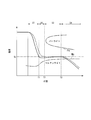
- FIG. 4 is a graph for explaining the heat treatment method of the present embodiment.
- 5A to 5C are schematic cross-sectional views for explaining the temperature difference between the inside and outside of the workpiece M of the present embodiment.
- the vertical axis represents temperature and the horizontal axis represents time.
- the solid line indicates the temperature change of the outer surface of the workpiece M, and the broken line indicates the temperature change inside the workpiece M.
- FIGS. 5A to 5C show the temperature distribution state of the workpiece M that changes sequentially with the passage of time in FIG. 5A shows the temperature distribution at time T1
- FIG. 5B shows the temperature distribution at time T2
- FIG. 5C shows the temperature distribution at time T3.
- the high temperature and low temperature are indicated by the shading of the dot pattern, and the dark dot pattern indicates the high temperature.
- an object to be processed (about 1000 ° C.) heated to an austenite structure state is in the vicinity of a transformation point Ms (first transformation point) at which transformation starts to a martensite structure.
- the mist cooling is performed by supplying a mist-like coolant to the target temperature Ta higher than the transformation point Ms (first step S1: rapid cooling step).
- the target temperature Ta is set within a range lower than the transformation point Ps (second transformation point) at which the workpiece M begins to transform into a pearlite structure and higher than the transformation point Ms at which the workpiece M begins to transform into a martensite structure. ing.
- the target temperature Ta is set between 370 ° C. and 550 ° C.
- the target temperature Ta is preferably set to a temperature in the vicinity of the transformation point Ms (a temperature that is higher than the transformation point Ms by about tens of degrees Celsius) in consideration of the process in the third step described later.
- the workpiece M is rapidly cooled by mist cooling to the target temperature Ta so as to avoid a transformation point Ps (so-called pearlite nose) that begins to transform into a pearlite structure.
- the workpiece M transported to the cooling chamber 160 is cooled by supplying and jetting a cooling liquid in a mist form from the nozzle portion 34 in the mist cooling device 30.
- the cooling liquid can be sprayed over the entire side surface (outer surface) of the workpiece M.
- the cooling liquid ejected from the nozzle portion 34 located obliquely below the workpiece M is formed by the tray 13 arranging the plate materials in a lattice shape, the gaps between the plate materials are formed. It can pass through and appropriately reaches the workpiece M and can be cooled.
- the nozzle portion 34 is provided over the entire length of the cooling chamber 160, in particular in the transport direction of the workpiece M by the injection from the nozzle portions 34 located on both ends of the supply pipe 32.
- the mist-like coolant can reach and cool the front and back surfaces of the glass. Since the mist-like coolant is supplied to all the outer surfaces of the workpiece M at a predetermined mist density, the workpiece M can be appropriately cooled by the latent heat of vaporization of the mist-like coolant.
- the coolant can be continuously supplied to exchange heat with the workpiece M. Therefore, as in the case where the workpiece M is immersed in the cooling liquid, the contact area with the cooling liquid is reduced by the bubbles generated by boiling the cooling liquid in contact with the high temperature workpiece M, and the cooling efficiency is lowered.
- the cooling process for the workpiece M can be continuously performed without causing the disadvantage that the amount of bubbles further increases to form a vapor film to form a heat insulating layer and the cooling efficiency is significantly reduced.
- the cooling gas may be supplied / injected from the outlet 24 of the gas cooling device 20 at the same time as the cooling liquid is supplied / injected in a mist form from the nozzle portion 34 of the mist cooling device 30. According to this method, the cooling liquid sprayed in a mist form in the cooling chamber 160 is diffused by the flow of the cooling gas, the atmosphere in the cooling chamber 160 can be made uniform, and cooling unevenness can be reduced. .
- mist cooling is cooling by latent heat of vaporization
- a temperature difference occurs between the inside and outside of the workpiece depending on the degree of mist contact (see FIG. 5A). For example, as shown in FIG. 4, the temperature of the outer surface of the object to be processed M decreases in a shorter time than the temperature inside the object to be processed M. The temperature difference will increase.
- the workpiece M is treated with the mist density of the first step.
- a mist-like coolant is supplied so that the mist is cooled with a smaller mist density (slow cooling step S2).
- slow cooling step S2 the mist density in the vicinity of the outer surface of the workpiece M in the cooling chamber 160 is reduced, and the workpiece M is cooled with a cooling efficiency lower than that in the first step S1.
- the temperature difference between the inside and outside of the object to be processed M is reduced by transferring heat from the high temperature inside to the low temperature outer surface by heat conduction.
- the entire temperature of the workpiece M becomes higher than the target temperature Ta due to heat conduction from the inside of the high temperature, and does not reach the transformation point (for example, the transformation point Ps) of another target that is not intended. Cooling is carried out as follows. That is, in the slow cooling step S2, cooling is performed so as to offset the overall temperature rise of the workpiece M due to heat conduction from the high temperature inside. In the slow cooling step S2, the cooling efficiency (mist density) is adjusted by the control device 41 so that the outer surface of the workpiece M does not reach the Ms transformation point due to the cooling.
- the slow cooling step S2 is performed until the temperature inside the workpiece M reaches the target temperature Ta. Thereby, it can prevent reliably that the temperature of the whole to-be-processed object M becomes higher than target temperature Ta.
- the temperature inside the workpiece M of the present embodiment uses the measurement result of the temperature sensor 80 provided on the outer surface of the workpiece M and the table data recorded in the memory of the control device 41. It is measured by referring to both. As shown in FIG. 5B, the workpiece M that has undergone such a slow cooling step S2 has a relaxed temperature distribution inside and outside compared to FIG. 5A.
- the supply of the mist-like coolant is stopped, and the workpiece M is held for a predetermined time (second step S3).
- second step S3 an increase in the temperature difference between the inside and outside of the workpiece M is suppressed during the mist cooling stop period, the temperature difference is reduced by heat conduction inside and outside the workpiece M, and the temperature of the workpiece M is substantially reduced. Make uniform.
- the mist cooling stop period of the second step S3 is performed until the temperature difference between the inside and outside of the workpiece M is within a predetermined threshold (for example, 10 ° C.).
- the mist cooling stop period of the second step S3 ends when the temperature difference between the inside and outside of the workpiece M is within a predetermined threshold while monitoring the temperature inside and outside the workpiece M.
- the mist cooling stop period of the second step S3 predicts the time during which the temperature difference between the inside and outside of the workpiece M is within a predetermined threshold from the temperature difference between the inside and outside of the workpiece M and the heat transfer coefficient, You may use the method of ending when the time passes.
- the workpiece M that has undergone the second step S3 is uniformized so that the internal and external temperatures become the target temperature Ta.
- the workpiece M is cooled to a temperature equal to or lower than the transformation point Ms (third step S4).
- the third step S4 by cooling the workpiece M in a state where the temperature difference between the inside and outside is relaxed through the first step S1, the slow cooling step S2, and the second step S3, to the transformation point Ms or less, The structure inside and outside the workpiece M is transformed into a martensite structure almost simultaneously.
- the target temperature Ta is a temperature that is higher than the transformation point Ms by about tens of degrees Celsius, the temperature difference between the inside and outside of the workpiece M caused by cooling in the third step S4 can be suppressed to a small level. Improvement can be achieved.
- the cooling in the third step S4 may be performed by restarting the supply of the mist-like coolant.
- the workpiece M may be cooled by supplying a cooling gas into the cooling chamber 160 by the gas cooling device 20, for example. That is, the workpiece M is directly cooled by supplying and injecting the cooling gas to the workpiece M from the jet outlet 24 in the gas cooling device 20.
- the workpiece M held at the quenching temperature is in the vicinity of the transformation point Ms where the structure of the workpiece M starts to transform into a martensite structure, and the transformation point Ms.
- a first step S1 for mist cooling by supplying a mist-like coolant to a higher target temperature Ta, and a state in which the supply of the mist-like coolant is stopped after the first step S1.
- a heat treatment method is performed in which a second step S3 that is held for a predetermined time and a third step S4 that cools the workpiece M to a temperature equal to or lower than the transformation point Ms after the second step S3.
- the mist cooling stop period in the second step S3 suppresses the expansion of the temperature difference inside and outside the workpiece M, and The temperature difference is alleviated by heat conduction inside and outside the processed material M.
- the structure inside and outside of the workpiece M is transformed into a martensite structure almost simultaneously by cooling the workpiece to a transformation point Ms or less in a state where the temperature difference between the inside and outside of the workpiece M is relaxed. Can do. Since the internal and external structures of the workpiece M are transformed almost simultaneously, no internal stress is generated in the workpiece M. Therefore, in this embodiment, non-uniformity and deformation of the tissue of the workpiece M can be suppressed.
- the mist cooling is performed between the first step S1 and the second step S3 so that the workpiece M is mist-cooled with a mist density smaller than the mist density of the first step S1.
- the slow cooling process S2 which supplies a liquid is implemented. Therefore, it is possible to prevent the entire temperature of the workpiece M from becoming higher than the target temperature Ta due to heat conduction from the inside of the high temperature and reaching the transformation point Ps of another structure which is not intended. That is, by slowly cooling the workpiece M before entering the second step, the temperature difference between the inside and outside of the workpiece M is relaxed, and the overall temperature rise of the workpiece M due to high-temperature internal heat conduction. Cooling is performed to offset this. By preventing the entire temperature of the object to be processed from becoming higher than the target temperature due to heat conduction inside and outside the object to be processed M, it is possible to more reliably suppress the unevenness and deformation of the structure of the object to be processed M.
- a fluorine-type inert liquid can be used, for example.
- a fluorinated inert liquid it is possible to prevent the material to be processed M from being adversely affected without affecting the constituent material of the object to be processed M.
- the fluorine-based inert liquid is nonflammable, safety can be improved.
- the fluorine-based inert liquid has a higher cooling potential because its boiling point is higher than that of water.
- problems such as oxidation and vapor film that occur when water is used can be suppressed.
- the fluorine-based inert liquid is excellent in heat transfer capability in terms of latent heat of vaporization, and can efficiently cool the workpiece M. Furthermore, since it is not necessary to wash even if the fluorine-based inert liquid adheres to the workpiece M, the productivity can be improved.
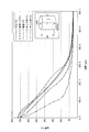
- FIG. 6 is a graph showing an experimental result of mist cooling.
- mist spray mist density
- SUS304 ⁇ 25 mm ⁇ 60 mm
- FIG. 6 shows that when the furnace pressure is 50 kPa and one nozzle is used, the mist spray amount is 8 L / min, the mist spray amount is 2 L / min, or the mist spray amount is 8 L / min ⁇
- the temperature change of the to-be-processed object in each spray condition at the time of changing with 2L / min-> 8L / min is shown.
- the cooling rate of the workpiece can be arbitrarily changed by changing the mist spray amount. In addition, the cooling rate can be suppressed by reducing the amount of mist spray on the way.
- FIG. 7 is a graph showing an experimental result of mist cooling.
- the temperature of the central part of the object to be processed changes when the cylindrical object to be processed of SUS304 ( ⁇ 25 mm ⁇ 60 mm) is subjected to mist cooling or immersion cooling.
- FIG. 7 shows a case where the pressure in the furnace is 50 kPa and the mist cooling is performed by injecting a constant mist spray amount of 27 L / min in total by 9 L / min from each nozzle using three nozzles and immersion cooling.
- the temperature change of the to-be-processed object in each cooling condition is shown.
- the mist cooling can cool the object to be processed faster than the immersion cooling in which the object to be processed is immersed in the coolant, and the cooling performance of the mist cooling is high.
- FIG. 8 is a graph showing an experimental result of mist cooling.
- a SUS304 ( ⁇ 80 mm ⁇ 80 mm) cylindrical workpiece is mist-cooled, a portion (diameter 1 / diameter) that is radially inward by a quarter of the diameter from the center and side surface of the workpiece. 4)
- FIG. 8 shows the temperature of each part in the workpiece when the pressure in the furnace is 50 kPa and three nozzles are used to inject 9 L / min from each nozzle and the total amount of mist spray is 27 L / min. It shows a change.
- FIG. 8 shows that when a certain mist is continuously sprayed and cooled, the temperature difference between the inside and outside of the object to be processed increases.
- FIG. 9 is a graph showing an experimental result of mist cooling.
- the pressure in the furnace is 50 kPa, and three nozzles are used to inject 9 L / min from each nozzle for a total of 27 L / min.
- the total amount of mist spray is 27 L / min.
- the temperature change of each part in the workpiece is shown when changing from min ⁇ 0 L / min ⁇ 27 L / min. As shown in FIG. 9, it can be seen that by temporarily stopping the spraying, the temperature difference between the inside and outside of the object to be processed is relaxed and the cooling proceeds.
- the above-described adjustment of the coolant supply amount using the motor 39 and the pump 38, the supply pressure adjustment, the supply time adjustment (frequency adjustment using a throttle valve, etc.), etc. are used. Can do.
- the temperature sensor 80 measures the temperature of the workpiece M, and the temperature inside the workpiece M is measured based on the measured temperature. You may provide the temperature sensor which measures this separately.
- the supply of the cooling liquid described in the above embodiment is normally performed under vacuum, but for example, the above-described inert gas may be added during mist cooling.
- the atmospheric pressure is high, the boiling point increases, and when the atmospheric pressure is low, the boiling point decreases. Therefore, by adjusting the amount of inert gas added and increasing the atmospheric pressure, the cooling capacity due to the latent heat of vaporization of the coolant can be increased, and conversely, by lowering the atmospheric pressure, the boiling point is lowered. The temperature difference with the liquid temperature is narrowed, and the cooling rate (cooling capacity) can be suppressed.
- the addition amount of the inert gas it becomes possible to control the cooling characteristics for the workpiece M, and it is possible to perform cooling with higher accuracy.
- mist cooling device 30 and the gas cooling device 20 are used in combination.
- the present invention is not limited to this, and only the mist cooling device 30 may be provided.
- oil, salt liquid, fluorine-based inert liquid, etc. are exemplified as the cooling liquid.
- water may be used when the influence of oxidation, vapor film, etc. is minor.
- an atmosphere in which the boiling point is 90 kPa (abs) to the boiling point is 80 ° C. for the same reason as in the case of using the fluorine-based inert liquid described above.
- the treatment is preferably performed under conditions of an adjustment pressure of about 48 kPa (abs).
- water is used as the cooling liquid, it can be safely discharged without any complicated post-treatment, either in the liquid phase or in the gas phase. It is also suitable from the viewpoint of protection.
- the supply of the mist-like coolant is stopped and held for a predetermined time in the second step S3.
- the supply of the mist-like coolant is not stopped and the first step S2 is not stopped.
- the mist cooling of the workpiece M at a mist density smaller than the mist density in the first step S1 for a predetermined time also suppresses the expansion of the temperature difference between the inside and outside of the workpiece M, and the inside and outside of the workpiece M The temperature difference can be relaxed by heat conduction.
Abstract
Description
上記油冷方式においては、冷却効率は優れているが、細かな冷却コントロールがほとんどできず被処理物が変形しやすい。一方、ガス冷却方式においては、ガスの流量制御等により冷却コントロールが容易であり、被処理物が変形しにくいが、冷却効率が低い。 In a heat treatment method in which quenching is performed by heating a metal material that is an object to be processed and then cooling, an oil cooling method or a gas cooling method is conventionally used when high speed cooling is required.
In the oil cooling system, the cooling efficiency is excellent, but fine cooling control is hardly performed and the workpiece is easily deformed. On the other hand, in the gas cooling system, the cooling control is easy by controlling the gas flow rate and the object to be processed is not easily deformed, but the cooling efficiency is low.
本発明では、第1工程で被処理物の内外に温度差が生じた場合でも、第2工程でのミスト冷却停止期間において被処理物の内外の温度差の拡大が抑えられると共に、被処理物の内外における熱伝導により温度差が緩和される。被処理物の内外の温度差が緩和された状態で、所定の組織の変態点以下まで被処理物を冷却することにより、被処理物の内外の組織をほぼ同時に所定の組織に変態させることができる。 According to a first aspect of the present invention, an object to be processed that is maintained at a predetermined temperature is in the vicinity of a first transformation point at which the structure of the object to be processed begins to transform into a predetermined structure, and from the first transformation point. A first step of mist cooling by supplying a mist-like cooling medium to a high target temperature, and after the first step, the workpiece is predetermined in a state where the supply of the mist-like cooling medium is stopped. A second step for holding time and a third step for cooling the object to be processed to a temperature not higher than the first transformation point after the second step.
In the present invention, even when a temperature difference occurs between the inside and outside of the object to be processed in the first process, the expansion of the temperature difference between the inside and outside of the object to be processed can be suppressed during the mist cooling stop period in the second process, and the object to be processed The temperature difference is alleviated by heat conduction inside and outside. With the temperature difference between the inside and outside of the object to be treated being relaxed, the inside and outside tissues of the object to be treated can be transformed into the prescribed structure almost simultaneously by cooling the object to be treated to a temperature below the transformation point of the prescribed structure. it can.
第2工程では被処理物の内外における熱伝導により温度差が緩和されるが、高温の内部からの熱伝導により被処理物の全体の温度が目標温度よりも高くなって、目的としない他の組織の変態点に達する可能性がある。本発明では、第2工程に入る前に被処理物を緩冷することによって、被処理物の内外の温度差を緩和すると共に、被処理物の内外における熱伝導により被処理物の全体の温度が目標温度より高くなることを防止できる。 Further, in the present invention, the mist-like shape is formed so that the object to be processed is mist-cooled with a mist density smaller than that of the first step between the first step and the second step. It is desirable to have a slow cooling process for supplying a cooling medium.
In the second step, the temperature difference is alleviated by heat conduction inside and outside the object to be treated, but the overall temperature of the object to be treated becomes higher than the target temperature due to heat conduction from the inside of the high temperature, It may reach the transformation point of the organization. In the present invention, by slowly cooling the workpiece before entering the second step, the temperature difference between the inside and outside of the workpiece is alleviated, and the overall temperature of the workpiece is determined by heat conduction inside and outside the workpiece. Can be prevented from becoming higher than the target temperature.
この場合には、被処理物の外表面の温度をモニタリングしつつ、被処理物の外表面の温度が目標温度に到達したときに緩冷を開始する。 Moreover, in this invention, it has the process of measuring the temperature of the outer surface of the said to-be-processed object, and when the measured temperature of the said outer surface reaches the said target temperature, from the said 1st process to the said slow cooling process. It is desirable to migrate.
In this case, slow cooling is started when the temperature of the outer surface of the workpiece reaches the target temperature while monitoring the temperature of the outer surface of the workpiece.
この場合には、被処理物の内部の温度をモニタリングしつつ、被処理物の内部の温度が目標温度に到達したときに緩冷を終了する。 Moreover, in this invention, it has the process of measuring the temperature inside the said to-be-processed object, and when the measured said internal temperature reaches the said target temperature, it transfers to the said 2nd process from the said slow cooling process. It is desirable.
In this case, the slow cooling is terminated when the temperature inside the workpiece reaches the target temperature while monitoring the temperature inside the workpiece.
この場合には、温度計測装置の設置数を削減できる。 In the present invention, it is desirable to measure the temperature inside the workpiece based on the temperature of the outer surface of the workpiece.
In this case, the number of temperature measuring devices installed can be reduced.
本発明では、第1工程で被処理物の内外に温度差が生じた場合でも、第2工程でのミスト密度が小さいミスト冷却期間において被処理物の内外の温度差の拡大が抑えられると共に、被処理物の内外における熱伝導により温度差が緩和される。被処理物の内外の温度差が緩和された状態で、所定の組織の変態点以下まで被処理物を冷却することにより、被処理物の内外の組織をほぼ同時に所定の組織に変態させることができる。 Further, the second invention according to the present invention is the first transformation in the vicinity of the first transformation point where the structure of the object to be treated begins to transform into the predetermined structure. A first step of mist cooling by supplying a mist-like cooling medium to a target temperature higher than the point, and a mist density lower than the mist density of the first step after the first step. And a second step of mist cooling for a predetermined time and a third step of cooling the object to be processed to a temperature not higher than the first transformation point after the second step.
In the present invention, even when a temperature difference occurs inside and outside the workpiece in the first step, the expansion of the temperature difference inside and outside the workpiece can be suppressed during the mist cooling period in which the mist density in the second step is small, The temperature difference is alleviated by heat conduction inside and outside the workpiece. With the temperature difference between the inside and outside of the object to be treated being relaxed, the inside and outside tissues of the object to be treated can be transformed into the prescribed structure almost simultaneously by cooling the object to be treated to a temperature below the transformation point of the prescribed structure. it can.
さらに、上記第1変態点は、マルテンサイト変態点であり、上記第2変態点は、パーライト変態点であることが望ましい。 In the present invention, the target temperature is between the first transformation point and a second transformation point at which the tissue starts to transform to a tissue other than the predetermined tissue at a temperature higher than the first transformation point. It is desirable to be set in.
Furthermore, it is desirable that the first transformation point is a martensitic transformation point and the second transformation point is a pearlite transformation point.
なお、以下の説明に用いる各図面では、各部材を認識可能な大きさとするため、各部材の縮尺を適宜変更している。
また、本実施形態では、本発明の熱処理方法を実施する熱処理装置として、多室型の真空熱処理炉(以下、単に「真空熱処理炉」と称する)を示す。 Hereinafter, embodiments of the present invention will be described with reference to FIGS. 1 to 5C.
In each drawing used for the following description, the scale of each member is appropriately changed to make each member a recognizable size.
In this embodiment, a multi-chamber vacuum heat treatment furnace (hereinafter simply referred to as “vacuum heat treatment furnace”) is shown as a heat treatment apparatus for performing the heat treatment method of the present invention.
真空熱処理炉(熱処理装置)100は、被処理物に対して熱処理を施す。真空熱処理炉100は、脱気室110、予熱室120、浸炭室130、拡散室140、降温室150、冷却室160が順次隣接して配置されている。被処理物は各室110~160に順次単列で搬送される。 FIG. 1 is an overall view of the vacuum heat treatment furnace of the present embodiment.
A vacuum heat treatment furnace (heat treatment apparatus) 100 performs heat treatment on an object to be processed. In the vacuum
図2は、冷却室160の正面断面図であり、図3は、図2におけるA-A線視断面図である。冷却室160は、真空容器1内に形成される。また、真空容器1内には、搬送装置10、ガス冷却装置20、ミスト冷却装置30、温度計測装置80からなる冷却ユニットCUが設けられている。 Since the vacuum
FIG. 2 is a front sectional view of the
なお、以下の説明においては、搬送装置10による被処理物Mの搬送方向を単に搬送方向と称する。 The conveying
In the following description, the conveyance direction of the workpiece M by the
被処理物Mとしては、ダイス鋼(SKD材)やハイス鋼(SKH材)等の鋼が例示される。本実施形態では、被処理物Mがダイス鋼(SKD61)である場合について以下説明する。 The
Examples of the workpiece M include steel such as die steel (SKD material) and high-speed steel (SKH material). In this embodiment, the case where the workpiece M is die steel (SKD61) will be described below.
冷却ガスとしては、例えばアルゴン、ヘリウム、窒素等の不活性ガスが用いられる。 The gas recovery /
As the cooling gas, for example, an inert gas such as argon, helium, or nitrogen is used.
冷却液としては、例えば油、ソルト液、後述するフッ素系不活性液体等を用いることができる。 The coolant recovery /
As the cooling liquid, for example, oil, salt liquid, a fluorine-based inert liquid described later, or the like can be used.
図4は、本実施形態の熱処理方法を説明するためのグラフである。図5A~図5Cは、本実施形態の被処理物Mの内外の温度差を説明するための模式断面図である。
図4において、縦軸は温度を、横軸は時間を示す。また、図4において、実線は被処理物Mの外表面の温度変化を、破線は被処理物Mの内部の温度変化を示す。また、図5A~図5Cは、図4の時間経過に伴って順次変化する被処理物Mの温度分布の状態を示している。図5Aは時間T1における温度分布を、図5Bは時間T2における温度分布を、図5Cは時間T3における温度分布を示す。なお、図5A~図5Cにおいては温度の高温低温をドットパターンの濃淡で示しており、濃いドットパターンが高温を示す。 Next, a procedure for cooling the heated workpiece M in the
FIG. 4 is a graph for explaining the heat treatment method of the present embodiment. 5A to 5C are schematic cross-sectional views for explaining the temperature difference between the inside and outside of the workpiece M of the present embodiment.
In FIG. 4, the vertical axis represents temperature and the horizontal axis represents time. In FIG. 4, the solid line indicates the temperature change of the outer surface of the workpiece M, and the broken line indicates the temperature change inside the workpiece M. 5A to 5C show the temperature distribution state of the workpiece M that changes sequentially with the passage of time in FIG. 5A shows the temperature distribution at time T1, FIG. 5B shows the temperature distribution at time T2, and FIG. 5C shows the temperature distribution at time T3. In FIGS. 5A to 5C, the high temperature and low temperature are indicated by the shading of the dot pattern, and the dark dot pattern indicates the high temperature.
目標温度Taは、被処理物Mがパーライト組織に変態し始める変態点Ps(第2変態点)より低く、被処理物Mがマルテンサイト組織に変態し始める変態点Msより高い範囲内において設定されている。本実施形態では、被処理物Mがダイス鋼(SKD61)であるので、目標温度Taは、370℃~550℃の間において設定されている。なお、目標温度Taは、後述する第3工程におけるプロセスを考慮して、変態点Ms近傍の温度(変態点Msより十数℃度程度高い温度)に設定することが好ましい。 In the heat treatment method of the present embodiment, first, an object to be processed (about 1000 ° C.) heated to an austenite structure state is in the vicinity of a transformation point Ms (first transformation point) at which transformation starts to a martensite structure. The mist cooling is performed by supplying a mist-like coolant to the target temperature Ta higher than the transformation point Ms (first step S1: rapid cooling step).
The target temperature Ta is set within a range lower than the transformation point Ps (second transformation point) at which the workpiece M begins to transform into a pearlite structure and higher than the transformation point Ms at which the workpiece M begins to transform into a martensite structure. ing. In this embodiment, since the workpiece M is die steel (SKD61), the target temperature Ta is set between 370 ° C. and 550 ° C. Note that the target temperature Ta is preferably set to a temperature in the vicinity of the transformation point Ms (a temperature that is higher than the transformation point Ms by about tens of degrees Celsius) in consideration of the process in the third step described later.
本実施形態では、冷却室160に搬送された被処理物Mに対して、ミスト冷却装置30におけるノズル部34から冷却液をミスト状に供給・噴射させることで冷却を行う。ノズル部34からの拡散角度が例えば図3に示すように90°に設定されることで、被処理物Mの側面(外表面)に対して全面的に冷却液を噴射させることができる。また、被処理物M(トレー13)の斜め下方に位置するノズル部34から噴出された冷却液は、トレー13が板材を格子状に配列することによって形成されていることから、板材の隙間を通過でき、適切に被処理物Mに到達して冷却することができる。また、ノズル部34が冷却室160の長さ方向全体に亘って設けられていることから、特に供給管32の両端側に位置するノズル部34からの噴射により、被処理物Mの搬送方向での前面及び背面にも、ミスト状の冷却液が到達して冷却することができる。ミスト状の冷却液が所定のミスト密度で被処理物Mの全ての外表面に供給されるため、ミスト状の冷却液の気化潜熱により適切に被処理物Mを冷却することができる。 In the first step S1, the workpiece M is rapidly cooled by mist cooling to the target temperature Ta so as to avoid a transformation point Ps (so-called pearlite nose) that begins to transform into a pearlite structure.
In the present embodiment, the workpiece M transported to the
なお、ミスト冷却装置30のノズル部34から冷却液をミスト状に供給・噴射させると同時に、ガス冷却装置20の噴出口24から冷却ガスを供給・噴射させてもよい。この方法によれば、冷却ガスの流れにより冷却室160にミスト状に噴霧された冷却液が拡散し、冷却室160の雰囲気を均一にすることができ、冷却ムラを低減させることが可能となる。 In the case of cooling using this mist-like coolant, the coolant can be continuously supplied to exchange heat with the workpiece M. Therefore, as in the case where the workpiece M is immersed in the cooling liquid, the contact area with the cooling liquid is reduced by the bubbles generated by boiling the cooling liquid in contact with the high temperature workpiece M, and the cooling efficiency is lowered. In addition, the cooling process for the workpiece M can be continuously performed without causing the disadvantage that the amount of bubbles further increases to form a vapor film to form a heat insulating layer and the cooling efficiency is significantly reduced.
The cooling gas may be supplied / injected from the
緩冷工程S2では、冷却室160内における、被処理物Mの外表面近傍のミスト密度を低下させ、第1工程S1よりも低い冷却効率で被処理物Mを冷却する。このとき、被処理物Mにおいては、熱伝導により高温の内部から低温の外表面に熱が伝わることにより被処理物Mの内外の温度差が小さくなる。 Next, in the heat treatment method of the present embodiment, when the measurement result of the
In the slow cooling step S2, the mist density in the vicinity of the outer surface of the workpiece M in the
このような緩冷工程S2を経た被処理物Mは、図5Bに示すように、図5Aと比べて内外の温度分布が緩和される。 The slow cooling step S2 is performed until the temperature inside the workpiece M reaches the target temperature Ta. Thereby, it can prevent reliably that the temperature of the whole to-be-processed object M becomes higher than target temperature Ta. In addition, the temperature inside the workpiece M of the present embodiment uses the measurement result of the
As shown in FIG. 5B, the workpiece M that has undergone such a slow cooling step S2 has a relaxed temperature distribution inside and outside compared to FIG. 5A.
第2工程S3では、ミスト冷却停止期間において被処理物Mの内外の温度差の拡大を抑えて、被処理物Mの内外における熱伝導により温度差を緩和し、被処理物Mの温度をほぼ均一にする。第2工程S3のミスト冷却停止期間は、被処理物Mの内外の温度差が所定の閾値(例えば10℃)以内になるまで実施する。本実施形態では、第2工程S3のミスト冷却停止期間は、被処理物Mの内外の温度をモニタリングしつつ、被処理物Mの内外の温度差が所定の閾値以内になった時に終了する。なお、第2工程S3のミスト冷却停止期間は、被処理物Mの内外の温度差と熱伝達率とから、被処理物Mの内外の温度差が所定の閾値以内になる時間を予測し、その時間が経過したときに終了する手法を用いてもよい。
このような第2工程S3を経た被処理物Mは、図5Cに示すように、内外の温度が目標温度Taとなるように均一化される。 Next, in the heat treatment method of the present embodiment, the supply of the mist-like coolant is stopped, and the workpiece M is held for a predetermined time (second step S3).
In the second step S3, an increase in the temperature difference between the inside and outside of the workpiece M is suppressed during the mist cooling stop period, the temperature difference is reduced by heat conduction inside and outside the workpiece M, and the temperature of the workpiece M is substantially reduced. Make uniform. The mist cooling stop period of the second step S3 is performed until the temperature difference between the inside and outside of the workpiece M is within a predetermined threshold (for example, 10 ° C.). In the present embodiment, the mist cooling stop period of the second step S3 ends when the temperature difference between the inside and outside of the workpiece M is within a predetermined threshold while monitoring the temperature inside and outside the workpiece M. The mist cooling stop period of the second step S3 predicts the time during which the temperature difference between the inside and outside of the workpiece M is within a predetermined threshold from the temperature difference between the inside and outside of the workpiece M and the heat transfer coefficient, You may use the method of ending when the time passes.
As shown in FIG. 5C, the workpiece M that has undergone the second step S3 is uniformized so that the internal and external temperatures become the target temperature Ta.
第3工程S4では、第1工程S1、緩冷工程S2、第2工程S3を経ることで内外の温度差が緩和された状態の被処理物Mを、変態点Ms以下まで冷却することにより、被処理物Mの内外の組織をほぼ同時にマルテンサイト組織に変態させる。なお、目標温度Taが、変態点Msより十数℃度程度高い温度であれば、第3工程S4における冷却によって生じる被処理物Mの内外の温度差を微小に抑えることが可能となり、品質の向上を図ることが可能となる。 In the heat treatment method of the present embodiment, finally, the workpiece M is cooled to a temperature equal to or lower than the transformation point Ms (third step S4).
In the third step S4, by cooling the workpiece M in a state where the temperature difference between the inside and outside is relaxed through the first step S1, the slow cooling step S2, and the second step S3, to the transformation point Ms or less, The structure inside and outside the workpiece M is transformed into a martensite structure almost simultaneously. In addition, if the target temperature Ta is a temperature that is higher than the transformation point Ms by about tens of degrees Celsius, the temperature difference between the inside and outside of the workpiece M caused by cooling in the third step S4 can be suppressed to a small level. Improvement can be achieved.
フッ素系不活性液体を用いた場合には、被処理物Mの構成材料を侵さず被処理物Mに悪影響を及ぼすことを防止できる。また、フッ素系不活性液体は、不燃性であるため、安全性も向上させることが可能である。また、フッ素系不活性液体は、その沸点が水よりも高いため、冷却ポテンシャルも高い。また、フッ素系不活性液体を用いた場合は、水を用いた場合に生じる酸化や蒸気膜等の問題も抑制することができる。また、フッ素系不活性液体は、蒸発潜熱の点でも熱伝達能力に優れており、被処理物Mを効率的に冷却することが可能である。さらに、被処理物Mにフッ素系不活性液体が付着しても洗浄する必要がないことから、生産性も向上させることができる。 In addition, as a cooling fluid in the said embodiment, a fluorine-type inert liquid can be used, for example.
When a fluorinated inert liquid is used, it is possible to prevent the material to be processed M from being adversely affected without affecting the constituent material of the object to be processed M. Further, since the fluorine-based inert liquid is nonflammable, safety can be improved. In addition, the fluorine-based inert liquid has a higher cooling potential because its boiling point is higher than that of water. In addition, when a fluorine-based inert liquid is used, problems such as oxidation and vapor film that occur when water is used can be suppressed. Further, the fluorine-based inert liquid is excellent in heat transfer capability in terms of latent heat of vaporization, and can efficiently cool the workpiece M. Furthermore, since it is not necessary to wash even if the fluorine-based inert liquid adheres to the workpiece M, the productivity can be improved.
以下、図6~図9に示すグラフを参照して、本発明の効果についてより明らかにする。 (Experimental example)
Hereinafter, the effects of the present invention will be clarified with reference to the graphs shown in FIGS.
図6は、炉内圧力を50kPaとして、1つのノズルを用いて、ミスト噴霧量を8L/minとした場合、ミスト噴霧量を2L/minとした場合、又は、ミスト噴霧量を8L/min→2L/min→8L/minと変化させた場合の、各噴霧条件での被処理物の温度変化を示している。
図6に示すように、ミスト噴霧量を変化させることにより被処理物の冷却速度を任意に変化させることができる。また、ミスト噴霧量を途中で少なくすることにより冷却速度を抑制できる。 FIG. 6 is a graph showing an experimental result of mist cooling. In this experiment, it was examined how the temperature at the center of the object to be processed changes when the amount of mist spray (mist density) on the cylindrical object to be processed of SUS304 (φ25 mm × 60 mm) is changed. .
FIG. 6 shows that when the furnace pressure is 50 kPa and one nozzle is used, the mist spray amount is 8 L / min, the mist spray amount is 2 L / min, or the mist spray amount is 8 L / min → The temperature change of the to-be-processed object in each spray condition at the time of changing with 2L / min-> 8L / min is shown.
As shown in FIG. 6, the cooling rate of the workpiece can be arbitrarily changed by changing the mist spray amount. In addition, the cooling rate can be suppressed by reducing the amount of mist spray on the way.
図7は、炉内圧力を50kPaとして、3つのノズルを用いて各ノズルから9L/minずつ、合計でミスト噴霧量を27L/minで一定噴射させてミスト冷却した場合と、浸漬冷却した場合の、各冷却条件での被処理物の温度変化を示している。
図7に示すように、被処理物を冷媒に浸して冷却する浸漬冷却よりも、ミスト冷却の方がより早く被処理物を冷却することができ、ミスト冷却の冷却性能が高いことが分かる。 FIG. 7 is a graph showing an experimental result of mist cooling. In this experiment, it was examined how the temperature of the central part of the object to be processed changes when the cylindrical object to be processed of SUS304 (φ25 mm × 60 mm) is subjected to mist cooling or immersion cooling.
FIG. 7 shows a case where the pressure in the furnace is 50 kPa and the mist cooling is performed by injecting a constant mist spray amount of 27 L / min in total by 9 L / min from each nozzle using three nozzles and immersion cooling. The temperature change of the to-be-processed object in each cooling condition is shown.
As shown in FIG. 7, it can be seen that the mist cooling can cool the object to be processed faster than the immersion cooling in which the object to be processed is immersed in the coolant, and the cooling performance of the mist cooling is high.
図8は、炉内圧力を50kPaとして、3つのノズルを用いて各ノズルから9L/minずつ、合計でミスト噴霧量を27L/minで一定噴射させた場合の、被処理物における各部分の温度変化を示している。
図8に示すように、一定のミストを噴霧し続けて冷却すると、被処理物の内外の温度差の拡大が進行することが分かる。 FIG. 8 is a graph showing an experimental result of mist cooling. In this experiment, when a SUS304 (φ80 mm × 80 mm) cylindrical workpiece is mist-cooled, a portion (
FIG. 8 shows the temperature of each part in the workpiece when the pressure in the furnace is 50 kPa and three nozzles are used to inject 9 L / min from each nozzle and the total amount of mist spray is 27 L / min. It shows a change.
As shown in FIG. 8, it can be seen that when a certain mist is continuously sprayed and cooled, the temperature difference between the inside and outside of the object to be processed increases.
図9は、炉内圧力を50kPaとして、3つのノズルを用いて各ノズルから9L/minずつ、合計でミスト噴霧量を27L/minで噴射させる場合であって、ミスト噴霧量の総量を27L/min→0L/min→27L/minと変化させた場合の、被処理物における各部分の温度変化を示している。
図9に示すように、噴霧を一時停止することにより、被処理物の内外の温度差が緩和されて、冷却が進行することが分かる。 FIG. 9 is a graph showing an experimental result of mist cooling. In this experiment, when the mist cooling for the cylindrical workpiece of SUS304 (φ80 mm × 80 mm) was temporarily stopped in the middle, each of the center,
FIG. 9 shows a case in which the pressure in the furnace is 50 kPa, and three nozzles are used to inject 9 L / min from each nozzle for a total of 27 L / min. The total amount of mist spray is 27 L / min. The temperature change of each part in the workpiece is shown when changing from min → 0 L / min → 27 L / min.
As shown in FIG. 9, it can be seen that by temporarily stopping the spraying, the temperature difference between the inside and outside of the object to be processed is relaxed and the cooling proceeds.
通常、雰囲気圧が高いと沸点は上がり、雰囲気圧が低いと沸点が下がる。そのため、不活性ガスの添加量を調整して、雰囲気圧を上昇させることにより、冷却液の気化潜熱による冷却能力を高めることができ、逆に雰囲気圧を下降させることにより、沸点が下がって供給液温度との温度差が狭まり冷却速度(冷却能力)を抑えることができる。
このように、不活性ガスの添加量を調整することにより、被処理物Mに対する冷却特性を制御することも可能になり、より高精度の冷却を実施することができる。 In addition, the supply of the cooling liquid described in the above embodiment is normally performed under vacuum, but for example, the above-described inert gas may be added during mist cooling.
Usually, when the atmospheric pressure is high, the boiling point increases, and when the atmospheric pressure is low, the boiling point decreases. Therefore, by adjusting the amount of inert gas added and increasing the atmospheric pressure, the cooling capacity due to the latent heat of vaporization of the coolant can be increased, and conversely, by lowering the atmospheric pressure, the boiling point is lowered. The temperature difference with the liquid temperature is narrowed, and the cooling rate (cooling capacity) can be suppressed.
Thus, by adjusting the addition amount of the inert gas, it becomes possible to control the cooling characteristics for the workpiece M, and it is possible to perform cooling with higher accuracy.
冷却液として水を用いた場合には、液相または気相のいずれであっても、煩雑な後処理を要することなく安全に排出することが可能であり、後処理に係るコスト面及び地球環境保護の観点からも好適である。 In the above embodiment, oil, salt liquid, fluorine-based inert liquid, etc. are exemplified as the cooling liquid. However, water may be used when the influence of oxidation, vapor film, etc. is minor. When water is used as the mist-like coolant, an atmosphere in which the boiling point is 90 kPa (abs) to the boiling point is 80 ° C. for the same reason as in the case of using the fluorine-based inert liquid described above. The treatment is preferably performed under conditions of an adjustment pressure of about 48 kPa (abs).
When water is used as the cooling liquid, it can be safely discharged without any complicated post-treatment, either in the liquid phase or in the gas phase. It is also suitable from the viewpoint of protection.
30…ミスト冷却装置
32…供給管
34…ノズル部
41…制御装置
80…温度センサ
100…真空熱処理炉(熱処理装置)
160…冷却室
CU…冷却ユニット
M…被処理物
S1…第1工程
S2…緩冷工程
S3…第2工程
S4…第3工程 20 ...
160 ... Cooling chamber CU ... Cooling unit M ... Object to be processed S1 ... First step S2 ... Slow cooling step S3 ... Second step S4 ... Third step
Claims (8)
- 所定温度に保持された被処理物を、該被処理物の組織が所定の組織に変態し始める第1変態点の近傍であって該第1変態点より高い目標温度まで、ミスト状の冷却媒体を供給することによってミスト冷却する第1工程と、
前記第1工程の後に、前記被処理物を、前記ミスト状の冷却媒体の供給を停止した状態で所定時間保持する第2工程と、
前記第2工程の後に、前記被処理物を、前記第1変態点以下の温度まで冷却する第3工程とを有する熱処理方法。 A mist-like cooling medium in the vicinity of the first transformation point at which the structure of the object to be treated begins to transform into the predetermined structure and to a target temperature higher than the first transformation point. A first step of cooling the mist by supplying
After the first step, the second step of holding the object to be processed for a predetermined time in a state where the supply of the mist-like cooling medium is stopped;
And a third step of cooling the workpiece to a temperature not higher than the first transformation point after the second step. - 前記第1工程と前記第2工程との間において、前記被処理物を、前記第1工程のミスト密度よりも小さいミスト密度でミスト冷却するように、前記ミスト状の冷却媒体を供給する緩冷工程を有する請求項1に記載の熱処理方法。 Slow cooling that supplies the mist-like cooling medium so that the object to be processed is mist-cooled with a mist density smaller than that of the first step between the first step and the second step. The heat processing method of Claim 1 which has a process.
- 前記被処理物の外表面の温度を計測する工程を有し、
計測した前記外表面の温度が前記目標温度に到達した時に、前記第1工程から前記緩冷工程に移行する請求項2に記載の熱処理方法。 Measuring the temperature of the outer surface of the workpiece,
The heat treatment method according to claim 2, wherein when the measured temperature of the outer surface reaches the target temperature, the first cooling process shifts to the slow cooling process. - 前記被処理物の内部の温度を計測する工程を有し、
計測した前記内部の温度が前記目標温度に到達した時に、前記緩冷工程から前記第2工程に移行する請求項2または3に記載の熱処理方法。 Measuring the temperature inside the workpiece,
The heat processing method of Claim 2 or 3 which transfers to the said 2nd process from the said slow cooling process, when the measured said internal temperature reaches | attains the said target temperature. - 前記被処理物の外表面の温度に基づいて、前記被処理物の内部の温度を計測する請求項4に記載の熱処理方法。 The heat treatment method according to claim 4, wherein the temperature inside the workpiece is measured based on the temperature of the outer surface of the workpiece.
- 所定温度に保持された被処理物を、該被処理物の組織が所定の組織に変態し始める第1変態点の近傍であって該第1変態点より高い目標温度まで、ミスト状の冷却媒体を供給することによってミスト冷却する第1工程と、
前記第1工程の後に、前記被処理物を、前記第1工程のミスト密度よりも小さいミスト密度で所定時間ミスト冷却する第2工程と、
前記第2工程の後に、前記被処理物を、前記第1変態点以下の温度まで冷却する第3工程とを有する熱処理方法。 A mist-like cooling medium in the vicinity of the first transformation point at which the structure of the object to be treated begins to transform into the predetermined structure and to a target temperature higher than the first transformation point. A first step of cooling the mist by supplying
After the first step, the second step of mist cooling the object to be processed at a mist density lower than the mist density of the first step for a predetermined time;
And a third step of cooling the workpiece to a temperature not higher than the first transformation point after the second step. - 前記目標温度は、前記第1変態点と、該第1変態点よりも高い温度で前記組織が前記所定の組織以外の組織に変態し始める第2変態点との間において設定されている請求項1~6のいずれか一項に記載の熱処理方法。 The target temperature is set between the first transformation point and a second transformation point at which the tissue starts to transform into a tissue other than the predetermined tissue at a temperature higher than the first transformation point. The heat treatment method according to any one of 1 to 6.
- 前記第1変態点は、マルテンサイト変態点であり、前記第2変態点は、パーライト変態点である請求項7に記載の熱処理方法。 The heat treatment method according to claim 7, wherein the first transformation point is a martensitic transformation point and the second transformation point is a pearlite transformation point.
Priority Applications (4)
| Application Number | Priority Date | Filing Date | Title |
|---|---|---|---|
| KR1020127026094A KR20120130336A (en) | 2010-03-25 | 2011-03-24 | Heat treatment method |
| CN201180015345.9A CN102822357B (en) | 2010-03-25 | 2011-03-24 | Heat treatment method |
| US13/636,530 US9593390B2 (en) | 2010-03-25 | 2011-03-24 | Heat treatment method |
| EP11759542.1A EP2551358B1 (en) | 2010-03-25 | 2011-03-24 | Heat treatment method |
Applications Claiming Priority (2)
| Application Number | Priority Date | Filing Date | Title |
|---|---|---|---|
| JP2010-070242 | 2010-03-25 | ||
| JP2010070242A JP5906005B2 (en) | 2010-03-25 | 2010-03-25 | Heat treatment method |
Publications (1)
| Publication Number | Publication Date |
|---|---|
| WO2011118737A1 true WO2011118737A1 (en) | 2011-09-29 |
Family
ID=44673282
Family Applications (1)
| Application Number | Title | Priority Date | Filing Date |
|---|---|---|---|
| PCT/JP2011/057249 WO2011118737A1 (en) | 2010-03-25 | 2011-03-24 | Heat treatment method |
Country Status (6)
| Country | Link |
|---|---|
| US (1) | US9593390B2 (en) |
| EP (1) | EP2551358B1 (en) |
| JP (1) | JP5906005B2 (en) |
| KR (1) | KR20120130336A (en) |
| CN (2) | CN105400932A (en) |
| WO (1) | WO2011118737A1 (en) |
Cited By (1)
| Publication number | Priority date | Publication date | Assignee | Title |
|---|---|---|---|---|
| US9617611B2 (en) | 2011-03-28 | 2017-04-11 | Ipsen, Inc. | Quenching process and apparatus for practicing said process |
Families Citing this family (11)
| Publication number | Priority date | Publication date | Assignee | Title |
|---|---|---|---|---|
| JP5342474B2 (en) * | 2010-02-25 | 2013-11-13 | 日本航空電子工業株式会社 | precision equipment |
| JP6043551B2 (en) * | 2012-09-05 | 2016-12-14 | 株式会社Ihi | Heat treatment method |
| US9458519B2 (en) * | 2012-09-28 | 2016-10-04 | Ipsen, Inc. | Process for cooling a metal workload in a multimedia quench system |
| EP2813584A1 (en) * | 2013-06-11 | 2014-12-17 | Linde Aktiengesellschaft | System and method for quenching a heated metallic object |
| WO2016080197A1 (en) | 2014-11-20 | 2016-05-26 | 株式会社Ihi | Heat treatment device and cooling device |
| CA2974514C (en) * | 2015-01-23 | 2019-09-17 | Arconic Inc. | Aluminum alloy products |
| US20180327874A1 (en) * | 2015-11-11 | 2018-11-15 | Nissan Motor Co., Ltd. | Gas quenching method |
| JP6742399B2 (en) * | 2016-03-23 | 2020-08-19 | 株式会社Ihi | Cooling device and heat treatment device |
| JP2019163490A (en) * | 2016-06-21 | 2019-09-26 | 株式会社日立製作所 | Cooling device |
| JP6536769B1 (en) * | 2017-11-24 | 2019-07-03 | Jfeスチール株式会社 | Crude oil tanker upper deck and bottom plate corrosion resistant steel, and crude oil tanker |
| CZ308471B6 (en) * | 2019-08-19 | 2020-09-02 | Západočeská Univerzita V Plzni | Method of manufacturing steel parts from AHS steel by controlled local cooling with a medium, using the formation of a multiphase structure with intermittent cooling at the required temperature |
Citations (7)
| Publication number | Priority date | Publication date | Assignee | Title |
|---|---|---|---|---|
| JPS5261119A (en) * | 1975-11-15 | 1977-05-20 | Toyo Bearing Mfg Co | Water marquenching method for high carbon steel |
| JPS5565318A (en) * | 1978-11-09 | 1980-05-16 | Mitsubishi Heavy Ind Ltd | Water hardening method |
| JPH1081913A (en) * | 1996-09-06 | 1998-03-31 | Ishikawajima Harima Heavy Ind Co Ltd | Isothermal quenching apparatus by gas cooling |
| JPH11153386A (en) | 1997-11-25 | 1999-06-08 | Ishikawajima Harima Heavy Ind Co Ltd | Multichamber multi-cooling vacuum furnace |
| JP2002194435A (en) * | 2000-12-25 | 2002-07-10 | Sanyo Special Steel Co Ltd | Method for suitably heating bearing steel in pusher furnace |
| JP2005163155A (en) * | 2003-12-05 | 2005-06-23 | Hirohisa Taniguchi | Metal heat treatment device |
| JP2008121064A (en) * | 2006-11-10 | 2008-05-29 | Daido Steel Co Ltd | Method for producing low strain quenched material |
Family Cites Families (11)
| Publication number | Priority date | Publication date | Assignee | Title |
|---|---|---|---|---|
| JPS58141323A (en) | 1982-02-12 | 1983-08-22 | Hitachi Ltd | Method and apparatus for quenching |
| US4504042A (en) * | 1982-02-16 | 1985-03-12 | Kruppert Enterprises, Inc. | Apparatus for heat treating steel |
| JPH0530146U (en) * | 1991-09-25 | 1993-04-20 | 日立金属株式会社 | High-strength spheroidal graphite cast iron manufacturing equipment |
| JP3341612B2 (en) | 1997-01-30 | 2002-11-05 | 日本鋼管株式会社 | Controlled cooling method and apparatus for hot rolled steel sheet |
| NL1006539C2 (en) | 1997-07-10 | 1999-01-12 | Skf Ind Trading & Dev | Method for performing a heat treatment on metal rings, and bearing ring thus obtained. |
| JP2000313920A (en) * | 1999-04-28 | 2000-11-14 | Sumitomo Metal Ind Ltd | Cooling apparatus of high temperature steel plate and cooling method thereof |
| US6443214B1 (en) * | 1999-12-07 | 2002-09-03 | Honda Giken Kogyo Kabushiki Kaisha | Method for heat treating mold cast product |
| CN1189577C (en) * | 2002-08-29 | 2005-02-16 | 上海交通大学 | Clean isothermal quenching or stepwise quenching process |
| CN101538643A (en) * | 2008-03-20 | 2009-09-23 | 上海市机械制造工艺研究所有限公司 | Process for quenching H13 steel by high-pressure gas stepped quick cooling |
| JP2010038531A (en) * | 2008-07-10 | 2010-02-18 | Ihi Corp | Heat treatment device |
| US20160059114A1 (en) * | 2014-08-26 | 2016-03-03 | Ryan Alanis | Light game system and method |
-
2010
- 2010-03-25 JP JP2010070242A patent/JP5906005B2/en not_active Expired - Fee Related
-
2011
- 2011-03-24 KR KR1020127026094A patent/KR20120130336A/en not_active Application Discontinuation
- 2011-03-24 CN CN201510985513.7A patent/CN105400932A/en active Pending
- 2011-03-24 US US13/636,530 patent/US9593390B2/en active Active
- 2011-03-24 EP EP11759542.1A patent/EP2551358B1/en active Active
- 2011-03-24 WO PCT/JP2011/057249 patent/WO2011118737A1/en active Application Filing
- 2011-03-24 CN CN201180015345.9A patent/CN102822357B/en not_active Expired - Fee Related
Patent Citations (7)
| Publication number | Priority date | Publication date | Assignee | Title |
|---|---|---|---|---|
| JPS5261119A (en) * | 1975-11-15 | 1977-05-20 | Toyo Bearing Mfg Co | Water marquenching method for high carbon steel |
| JPS5565318A (en) * | 1978-11-09 | 1980-05-16 | Mitsubishi Heavy Ind Ltd | Water hardening method |
| JPH1081913A (en) * | 1996-09-06 | 1998-03-31 | Ishikawajima Harima Heavy Ind Co Ltd | Isothermal quenching apparatus by gas cooling |
| JPH11153386A (en) | 1997-11-25 | 1999-06-08 | Ishikawajima Harima Heavy Ind Co Ltd | Multichamber multi-cooling vacuum furnace |
| JP2002194435A (en) * | 2000-12-25 | 2002-07-10 | Sanyo Special Steel Co Ltd | Method for suitably heating bearing steel in pusher furnace |
| JP2005163155A (en) * | 2003-12-05 | 2005-06-23 | Hirohisa Taniguchi | Metal heat treatment device |
| JP2008121064A (en) * | 2006-11-10 | 2008-05-29 | Daido Steel Co Ltd | Method for producing low strain quenched material |
Cited By (1)
| Publication number | Priority date | Publication date | Assignee | Title |
|---|---|---|---|---|
| US9617611B2 (en) | 2011-03-28 | 2017-04-11 | Ipsen, Inc. | Quenching process and apparatus for practicing said process |
Also Published As
| Publication number | Publication date |
|---|---|
| CN102822357B (en) | 2016-11-23 |
| EP2551358A1 (en) | 2013-01-30 |
| JP2011202228A (en) | 2011-10-13 |
| US20130008567A1 (en) | 2013-01-10 |
| CN105400932A (en) | 2016-03-16 |
| KR20120130336A (en) | 2012-11-30 |
| EP2551358B1 (en) | 2020-11-18 |
| CN102822357A (en) | 2012-12-12 |
| JP5906005B2 (en) | 2016-04-20 |
| US9593390B2 (en) | 2017-03-14 |
| EP2551358A4 (en) | 2015-02-18 |
Similar Documents
| Publication | Publication Date | Title |
|---|---|---|
| WO2011118737A1 (en) | Heat treatment method | |
| JP5821987B2 (en) | Heat treatment apparatus and heat treatment method | |
| WO2010005083A1 (en) | Heat treatment apparatus | |
| JP5588661B2 (en) | Mist cooling device and heat treatment device | |
| US20120028202A1 (en) | Heat treatment device and heat treatment method | |
| EP3006576B1 (en) | Device for individual quench hardening of technical equipment components | |
| JP2014051695A (en) | Heat treatment apparatus, and heat treatment method | |
| JP6742399B2 (en) | Cooling device and heat treatment device | |
| JP5811199B2 (en) | Heat treatment equipment | |
| JP5991282B2 (en) | Steel strip manufacturing method and manufacturing equipment | |
| JP2019210549A (en) | Method for cooling steel sheet, cooling system for steel sheet, and method for manufacturing steel sheet | |
| JP2010121160A (en) | Apparatus and method for cooling metallic strip | |
| JP3867073B2 (en) | Cooling apparatus and cooling method for hot rolled steel sheet | |
| WO2023105846A1 (en) | Steel strip production device, continuous annealing facility, and production method | |
| JP2014095548A (en) | Thermal treatment device and thermal treatment method | |
| KR200194293Y1 (en) | Cooling station of a cvd device | |
| KR20120060390A (en) | Apparatus for preventing yellowing of ahss |
Legal Events
| Date | Code | Title | Description |
|---|---|---|---|
| WWE | Wipo information: entry into national phase |
Ref document number: 201180015345.9 Country of ref document: CN |
|
| 121 | Ep: the epo has been informed by wipo that ep was designated in this application |
Ref document number: 11759542 Country of ref document: EP Kind code of ref document: A1 |
|
| WWE | Wipo information: entry into national phase |
Ref document number: 13636530 Country of ref document: US |
|
| NENP | Non-entry into the national phase |
Ref country code: DE |
|
| WWE | Wipo information: entry into national phase |
Ref document number: 8499/DELNP/2012 Country of ref document: IN |
|
| ENP | Entry into the national phase |
Ref document number: 20127026094 Country of ref document: KR Kind code of ref document: A |
|
| WWE | Wipo information: entry into national phase |
Ref document number: 2011759542 Country of ref document: EP |