WO2011114609A1 - Device for eliminating n2o within exhaust gas and method for eliminating n2o - Google Patents
Device for eliminating n2o within exhaust gas and method for eliminating n2o Download PDFInfo
- Publication number
- WO2011114609A1 WO2011114609A1 PCT/JP2011/000329 JP2011000329W WO2011114609A1 WO 2011114609 A1 WO2011114609 A1 WO 2011114609A1 JP 2011000329 W JP2011000329 W JP 2011000329W WO 2011114609 A1 WO2011114609 A1 WO 2011114609A1
- Authority
- WO
- WIPO (PCT)
- Prior art keywords
- catalyst
- gas
- removal
- catalyst packed
- valve
- Prior art date
Links
- 238000000034 method Methods 0.000 title claims description 27
- 239000003054 catalyst Substances 0.000 claims abstract description 154
- 238000000354 decomposition reaction Methods 0.000 claims abstract description 42
- 229910021536 Zeolite Inorganic materials 0.000 claims description 15
- 239000010457 zeolite Substances 0.000 claims description 15
- 230000008859 change Effects 0.000 claims description 6
- 230000008569 process Effects 0.000 claims description 6
- 230000006866 deterioration Effects 0.000 claims description 4
- 230000032683 aging Effects 0.000 claims description 2
- 230000037361 pathway Effects 0.000 abstract 2
- 230000015556 catabolic process Effects 0.000 abstract 1
- 238000006731 degradation reaction Methods 0.000 abstract 1
- 230000008030 elimination Effects 0.000 abstract 1
- 238000003379 elimination reaction Methods 0.000 abstract 1
- 239000007789 gas Substances 0.000 description 57
- 230000009467 reduction Effects 0.000 description 8
- 239000010801 sewage sludge Substances 0.000 description 5
- CURLTUGMZLYLDI-UHFFFAOYSA-N Carbon dioxide Chemical compound O=C=O CURLTUGMZLYLDI-UHFFFAOYSA-N 0.000 description 4
- 238000004364 calculation method Methods 0.000 description 4
- XEEYBQQBJWHFJM-UHFFFAOYSA-N Iron Chemical compound [Fe] XEEYBQQBJWHFJM-UHFFFAOYSA-N 0.000 description 3
- HNPSIPDUKPIQMN-UHFFFAOYSA-N dioxosilane;oxo(oxoalumanyloxy)alumane Chemical compound O=[Si]=O.O=[Al]O[Al]=O HNPSIPDUKPIQMN-UHFFFAOYSA-N 0.000 description 3
- QGZKDVFQNNGYKY-UHFFFAOYSA-N Ammonia Chemical compound N QGZKDVFQNNGYKY-UHFFFAOYSA-N 0.000 description 2
- GQPLMRYTRLFLPF-UHFFFAOYSA-N Nitrous Oxide Chemical compound [O-][N+]#N GQPLMRYTRLFLPF-UHFFFAOYSA-N 0.000 description 2
- 229910002092 carbon dioxide Inorganic materials 0.000 description 2
- 239000001569 carbon dioxide Substances 0.000 description 2
- 230000003197 catalytic effect Effects 0.000 description 2
- 230000000052 comparative effect Effects 0.000 description 2
- 230000007423 decrease Effects 0.000 description 2
- 238000010586 diagram Methods 0.000 description 2
- 230000000694 effects Effects 0.000 description 2
- 238000005516 engineering process Methods 0.000 description 2
- 239000005431 greenhouse gas Substances 0.000 description 2
- 229910052742 iron Inorganic materials 0.000 description 2
- 238000004519 manufacturing process Methods 0.000 description 2
- 238000010792 warming Methods 0.000 description 2
- QGZKDVFQNNGYKY-UHFFFAOYSA-O Ammonium Chemical compound [NH4+] QGZKDVFQNNGYKY-UHFFFAOYSA-O 0.000 description 1
- 230000009471 action Effects 0.000 description 1
- PNEYBMLMFCGWSK-UHFFFAOYSA-N aluminium oxide Inorganic materials [O-2].[O-2].[O-2].[Al+3].[Al+3] PNEYBMLMFCGWSK-UHFFFAOYSA-N 0.000 description 1
- 229910021529 ammonia Inorganic materials 0.000 description 1
- 239000011230 binding agent Substances 0.000 description 1
- 239000003638 chemical reducing agent Substances 0.000 description 1
- 238000007599 discharging Methods 0.000 description 1
- 238000011156 evaluation Methods 0.000 description 1
- 238000001125 extrusion Methods 0.000 description 1
- 230000005484 gravity Effects 0.000 description 1
- 230000036541 health Effects 0.000 description 1
- -1 iron ions Chemical class 0.000 description 1
- 238000000465 moulding Methods 0.000 description 1
- 239000001272 nitrous oxide Substances 0.000 description 1
- 239000008188 pellet Substances 0.000 description 1
- 239000000843 powder Substances 0.000 description 1
- 230000002035 prolonged effect Effects 0.000 description 1
Images

Classifications
-
- B—PERFORMING OPERATIONS; TRANSPORTING
- B01—PHYSICAL OR CHEMICAL PROCESSES OR APPARATUS IN GENERAL
- B01D—SEPARATION
- B01D53/00—Separation of gases or vapours; Recovering vapours of volatile solvents from gases; Chemical or biological purification of waste gases, e.g. engine exhaust gases, smoke, fumes, flue gases, aerosols
- B01D53/34—Chemical or biological purification of waste gases
- B01D53/92—Chemical or biological purification of waste gases of engine exhaust gases
- B01D53/94—Chemical or biological purification of waste gases of engine exhaust gases by catalytic processes
- B01D53/9404—Removing only nitrogen compounds
- B01D53/9409—Nitrogen oxides
- B01D53/9413—Processes characterised by a specific catalyst
- B01D53/9427—Processes characterised by a specific catalyst for removing nitrous oxide
-
- B—PERFORMING OPERATIONS; TRANSPORTING
- B01—PHYSICAL OR CHEMICAL PROCESSES OR APPARATUS IN GENERAL
- B01D—SEPARATION
- B01D53/00—Separation of gases or vapours; Recovering vapours of volatile solvents from gases; Chemical or biological purification of waste gases, e.g. engine exhaust gases, smoke, fumes, flue gases, aerosols
- B01D53/34—Chemical or biological purification of waste gases
- B01D53/74—General processes for purification of waste gases; Apparatus or devices specially adapted therefor
- B01D53/86—Catalytic processes
-
- B—PERFORMING OPERATIONS; TRANSPORTING
- B01—PHYSICAL OR CHEMICAL PROCESSES OR APPARATUS IN GENERAL
- B01D—SEPARATION
- B01D53/00—Separation of gases or vapours; Recovering vapours of volatile solvents from gases; Chemical or biological purification of waste gases, e.g. engine exhaust gases, smoke, fumes, flue gases, aerosols
- B01D53/34—Chemical or biological purification of waste gases
- B01D53/46—Removing components of defined structure
- B01D53/54—Nitrogen compounds
- B01D53/56—Nitrogen oxides
-
- B—PERFORMING OPERATIONS; TRANSPORTING
- B01—PHYSICAL OR CHEMICAL PROCESSES OR APPARATUS IN GENERAL
- B01D—SEPARATION
- B01D53/00—Separation of gases or vapours; Recovering vapours of volatile solvents from gases; Chemical or biological purification of waste gases, e.g. engine exhaust gases, smoke, fumes, flue gases, aerosols
- B01D53/34—Chemical or biological purification of waste gases
- B01D53/74—General processes for purification of waste gases; Apparatus or devices specially adapted therefor
- B01D53/86—Catalytic processes
- B01D53/8621—Removing nitrogen compounds
- B01D53/8625—Nitrogen oxides
- B01D53/8631—Processes characterised by a specific device
-
- B—PERFORMING OPERATIONS; TRANSPORTING
- B01—PHYSICAL OR CHEMICAL PROCESSES OR APPARATUS IN GENERAL
- B01J—CHEMICAL OR PHYSICAL PROCESSES, e.g. CATALYSIS OR COLLOID CHEMISTRY; THEIR RELEVANT APPARATUS
- B01J29/00—Catalysts comprising molecular sieves
- B01J29/04—Catalysts comprising molecular sieves having base-exchange properties, e.g. crystalline zeolites
- B01J29/06—Crystalline aluminosilicate zeolites; Isomorphous compounds thereof
- B01J29/064—Crystalline aluminosilicate zeolites; Isomorphous compounds thereof containing iron group metals, noble metals or copper
- B01J29/072—Iron group metals or copper
-
- B—PERFORMING OPERATIONS; TRANSPORTING
- B01—PHYSICAL OR CHEMICAL PROCESSES OR APPARATUS IN GENERAL
- B01J—CHEMICAL OR PHYSICAL PROCESSES, e.g. CATALYSIS OR COLLOID CHEMISTRY; THEIR RELEVANT APPARATUS
- B01J29/00—Catalysts comprising molecular sieves
- B01J29/04—Catalysts comprising molecular sieves having base-exchange properties, e.g. crystalline zeolites
- B01J29/06—Crystalline aluminosilicate zeolites; Isomorphous compounds thereof
- B01J29/40—Crystalline aluminosilicate zeolites; Isomorphous compounds thereof of the pentasil type, e.g. types ZSM-5, ZSM-8 or ZSM-11, as exemplified by patent documents US3702886, GB1334243 and US3709979, respectively
- B01J29/42—Crystalline aluminosilicate zeolites; Isomorphous compounds thereof of the pentasil type, e.g. types ZSM-5, ZSM-8 or ZSM-11, as exemplified by patent documents US3702886, GB1334243 and US3709979, respectively containing iron group metals, noble metals or copper
- B01J29/46—Iron group metals or copper
-
- B—PERFORMING OPERATIONS; TRANSPORTING
- B01—PHYSICAL OR CHEMICAL PROCESSES OR APPARATUS IN GENERAL
- B01J—CHEMICAL OR PHYSICAL PROCESSES, e.g. CATALYSIS OR COLLOID CHEMISTRY; THEIR RELEVANT APPARATUS
- B01J29/00—Catalysts comprising molecular sieves
- B01J29/04—Catalysts comprising molecular sieves having base-exchange properties, e.g. crystalline zeolites
- B01J29/06—Crystalline aluminosilicate zeolites; Isomorphous compounds thereof
- B01J29/70—Crystalline aluminosilicate zeolites; Isomorphous compounds thereof of types characterised by their specific structure not provided for in groups B01J29/08 - B01J29/65
- B01J29/72—Crystalline aluminosilicate zeolites; Isomorphous compounds thereof of types characterised by their specific structure not provided for in groups B01J29/08 - B01J29/65 containing iron group metals, noble metals or copper
- B01J29/76—Iron group metals or copper
- B01J29/7615—Zeolite Beta
-
- B—PERFORMING OPERATIONS; TRANSPORTING
- B01—PHYSICAL OR CHEMICAL PROCESSES OR APPARATUS IN GENERAL
- B01J—CHEMICAL OR PHYSICAL PROCESSES, e.g. CATALYSIS OR COLLOID CHEMISTRY; THEIR RELEVANT APPARATUS
- B01J35/00—Catalysts, in general, characterised by their form or physical properties
- B01J35/40—Catalysts, in general, characterised by their form or physical properties characterised by dimensions, e.g. grain size
-
- B—PERFORMING OPERATIONS; TRANSPORTING
- B01—PHYSICAL OR CHEMICAL PROCESSES OR APPARATUS IN GENERAL
- B01J—CHEMICAL OR PHYSICAL PROCESSES, e.g. CATALYSIS OR COLLOID CHEMISTRY; THEIR RELEVANT APPARATUS
- B01J35/00—Catalysts, in general, characterised by their form or physical properties
- B01J35/50—Catalysts, in general, characterised by their form or physical properties characterised by their shape or configuration
- B01J35/56—Foraminous structures having flow-through passages or channels, e.g. grids or three-dimensional monoliths
-
- B—PERFORMING OPERATIONS; TRANSPORTING
- B01—PHYSICAL OR CHEMICAL PROCESSES OR APPARATUS IN GENERAL
- B01J—CHEMICAL OR PHYSICAL PROCESSES, e.g. CATALYSIS OR COLLOID CHEMISTRY; THEIR RELEVANT APPARATUS
- B01J37/00—Processes, in general, for preparing catalysts; Processes, in general, for activation of catalysts
- B01J37/02—Impregnation, coating or precipitation
- B01J37/024—Multiple impregnation or coating
- B01J37/0246—Coatings comprising a zeolite
-
- F—MECHANICAL ENGINEERING; LIGHTING; HEATING; WEAPONS; BLASTING
- F23—COMBUSTION APPARATUS; COMBUSTION PROCESSES
- F23J—REMOVAL OR TREATMENT OF COMBUSTION PRODUCTS OR COMBUSTION RESIDUES; FLUES
- F23J15/00—Arrangements of devices for treating smoke or fumes
- F23J15/02—Arrangements of devices for treating smoke or fumes of purifiers, e.g. for removing noxious material
-
- B—PERFORMING OPERATIONS; TRANSPORTING
- B01—PHYSICAL OR CHEMICAL PROCESSES OR APPARATUS IN GENERAL
- B01D—SEPARATION
- B01D2255/00—Catalysts
- B01D2255/20—Metals or compounds thereof
- B01D2255/207—Transition metals
- B01D2255/20738—Iron
-
- B—PERFORMING OPERATIONS; TRANSPORTING
- B01—PHYSICAL OR CHEMICAL PROCESSES OR APPARATUS IN GENERAL
- B01D—SEPARATION
- B01D2255/00—Catalysts
- B01D2255/50—Zeolites
-
- B—PERFORMING OPERATIONS; TRANSPORTING
- B01—PHYSICAL OR CHEMICAL PROCESSES OR APPARATUS IN GENERAL
- B01D—SEPARATION
- B01D2255/00—Catalysts
- B01D2255/90—Physical characteristics of catalysts
- B01D2255/904—Multiple catalysts
- B01D2255/9045—Multiple catalysts in parallel
-
- B—PERFORMING OPERATIONS; TRANSPORTING
- B01—PHYSICAL OR CHEMICAL PROCESSES OR APPARATUS IN GENERAL
- B01D—SEPARATION
- B01D2257/00—Components to be removed
- B01D2257/40—Nitrogen compounds
- B01D2257/402—Dinitrogen oxide
-
- B—PERFORMING OPERATIONS; TRANSPORTING
- B01—PHYSICAL OR CHEMICAL PROCESSES OR APPARATUS IN GENERAL
- B01D—SEPARATION
- B01D2258/00—Sources of waste gases
- B01D2258/01—Engine exhaust gases
-
- B—PERFORMING OPERATIONS; TRANSPORTING
- B01—PHYSICAL OR CHEMICAL PROCESSES OR APPARATUS IN GENERAL
- B01D—SEPARATION
- B01D2258/00—Sources of waste gases
- B01D2258/02—Other waste gases
- B01D2258/0283—Flue gases
-
- B—PERFORMING OPERATIONS; TRANSPORTING
- B01—PHYSICAL OR CHEMICAL PROCESSES OR APPARATUS IN GENERAL
- B01D—SEPARATION
- B01D2258/00—Sources of waste gases
- B01D2258/02—Other waste gases
- B01D2258/0283—Flue gases
- B01D2258/0291—Flue gases from waste incineration plants
-
- B—PERFORMING OPERATIONS; TRANSPORTING
- B01—PHYSICAL OR CHEMICAL PROCESSES OR APPARATUS IN GENERAL
- B01J—CHEMICAL OR PHYSICAL PROCESSES, e.g. CATALYSIS OR COLLOID CHEMISTRY; THEIR RELEVANT APPARATUS
- B01J2229/00—Aspects of molecular sieve catalysts not covered by B01J29/00
- B01J2229/10—After treatment, characterised by the effect to be obtained
- B01J2229/18—After treatment, characterised by the effect to be obtained to introduce other elements into or onto the molecular sieve itself
- B01J2229/186—After treatment, characterised by the effect to be obtained to introduce other elements into or onto the molecular sieve itself not in framework positions
-
- F—MECHANICAL ENGINEERING; LIGHTING; HEATING; WEAPONS; BLASTING
- F23—COMBUSTION APPARATUS; COMBUSTION PROCESSES
- F23J—REMOVAL OR TREATMENT OF COMBUSTION PRODUCTS OR COMBUSTION RESIDUES; FLUES
- F23J2215/00—Preventing emissions
- F23J2215/10—Nitrogen; Compounds thereof
- F23J2215/101—Nitrous oxide (N2O)
-
- F—MECHANICAL ENGINEERING; LIGHTING; HEATING; WEAPONS; BLASTING
- F23—COMBUSTION APPARATUS; COMBUSTION PROCESSES
- F23J—REMOVAL OR TREATMENT OF COMBUSTION PRODUCTS OR COMBUSTION RESIDUES; FLUES
- F23J2219/00—Treatment devices
- F23J2219/10—Catalytic reduction devices
-
- Y—GENERAL TAGGING OF NEW TECHNOLOGICAL DEVELOPMENTS; GENERAL TAGGING OF CROSS-SECTIONAL TECHNOLOGIES SPANNING OVER SEVERAL SECTIONS OF THE IPC; TECHNICAL SUBJECTS COVERED BY FORMER USPC CROSS-REFERENCE ART COLLECTIONS [XRACs] AND DIGESTS
- Y02—TECHNOLOGIES OR APPLICATIONS FOR MITIGATION OR ADAPTATION AGAINST CLIMATE CHANGE
- Y02C—CAPTURE, STORAGE, SEQUESTRATION OR DISPOSAL OF GREENHOUSE GASES [GHG]
- Y02C20/00—Capture or disposal of greenhouse gases
- Y02C20/10—Capture or disposal of greenhouse gases of nitrous oxide (N2O)
Definitions
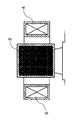
- FIG. 2 shows an explanatory diagram of the radial reactor.
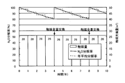
- the entire amount of the catalyst is frequently exchanged at a timing when the N 2 O decomposition rate becomes a predetermined value or less.
- N 2 O removal device of the present invention made to solve the above problems, a plurality of gas flow paths and N 2 O decomposition catalyst catalyst-packed layer filled is in each N 2 O removal apparatus arranged alternately
- the gas flow path adjacent to each other through the catalyst packed bed is composed of a gas introduction path and a gas discharge path, and each gas flow path is sequentially opened according to deterioration due to aging of the N 2 O catalyst.
- This is characterized in that a valve is provided for cumulatively increasing the number of use of.
- the catalyst packed layer is composed of a vertical layer having an opening / closing portion at an upper end and a lower end, and the vertical layer and the gas flow path are alternately arranged It is characterized by being arranged in parallel.
- the invention described in claim 3 is the N 2 O removal apparatus according to claim 1 or 2, characterized in that the N 2 O decomposition catalyst is a pellet-shaped iron-zeolite catalyst.
- N 2 O decomposition rate is a valve at the stage where falls below the target value of the N 2 O removal apparatus, catalyst loading used
- the most prolonged use catalyst packed layer By selectively stopping the valve of the gas introduction path for introducing the gas, replacing the catalyst in the catalyst packed bed with a new catalyst, and using it as a new catalyst packed bed, the N 2 O emission amount is reduced to a predetermined value. It is possible to reduce the total amount of the catalyst used to maintain the reduction target range.
- FIG. 3 is a top cross-sectional view of the N 2 O removal apparatus of the present invention. It is AA sectional drawing of FIG. It is BB sectional drawing of FIG. It is front sectional drawing of a radial reactor.
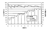
- N 2 O decomposition rate by N 2 O removal method of the present invention showing the amount of catalyst used.
- N 2 O decomposition rate according to the conventional N 2 O removal method is a diagram showing the amount of catalyst used.
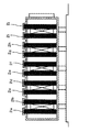
- the catalyst packed layer 2 (2a to 2j) is a vertical layer having an open / close portion at the upper end and the lower end, thereby facilitating the flow and discharge of the catalyst according to gravity. Therefore, the vertical layer is preferred from the viewpoint of improving the work of filling and exchanging the catalyst.
- Gas passage 1 has a gas inlet passage 11 for introducing the exhaust gas into N 2 O removal device, made from the gas discharge passage 12 for discharging the exhaust gas after catalytic treatment of N 2 O removal apparatus, these gas introduction passage 11 and gas discharge passages 12 are alternately arranged via the catalyst packed bed 2.
- An inlet valve 31 that controls gas introduction is provided at the inlet of the gas introduction path 11, and an outlet valve 32 that controls gas discharge is provided at the outlet of the gas discharge path 12.
- the valve 31a, the valve 32a, and the valve 32b are opened, and the remaining valves 31b to 31e and the valves 32c to 32 are closed so that the exhaust gas selectively flows through the catalyst packed layers 2a and 2b. Can do.
- the N 2 O resolution can be maintained at a predetermined level for the entire N 2 O removing apparatus.
- the deteriorated catalyst can be continuously used as the catalyst, so that the utilization rate of the N 2 O resolution is improved, and as a result, the total use amount of the catalyst is reduced. be able to.
- the results of trial calculation of the amount of catalyst necessary for carrying out the N 2 O removal treatment in the sewage sludge incinerator exhaust gas using the N 2 O removal apparatus shown in FIG. 1 are shown below.
- the N 2 O removing apparatus has 10 catalyst packed layers each filled with 4 m 3 of catalyst, and a total of 40 m 3 of catalyst is packed.
- the annual operating rate is calculated as 80% (290 days / year), and no allowance is considered for the amount of catalyst.
- the total amount of catalyst used in 10 years can be suppressed to 36 m 3 .
Landscapes
- Chemical & Material Sciences (AREA)
- Engineering & Computer Science (AREA)
- Chemical Kinetics & Catalysis (AREA)
- Materials Engineering (AREA)
- Organic Chemistry (AREA)
- Environmental & Geological Engineering (AREA)
- Analytical Chemistry (AREA)
- Oil, Petroleum & Natural Gas (AREA)
- General Chemical & Material Sciences (AREA)
- Biomedical Technology (AREA)
- Health & Medical Sciences (AREA)
- Crystallography & Structural Chemistry (AREA)
- Mechanical Engineering (AREA)
- General Engineering & Computer Science (AREA)
- Combustion & Propulsion (AREA)
- Exhaust Gas Treatment By Means Of Catalyst (AREA)
- Catalysts (AREA)
Abstract
Description
発明のN2O除去装置は、図1、図2に示すように、複数のガス流路1とN2O分解触媒が充填された触媒充填層2(2a~2j)を、各々交互に配列して有している。 Preferred embodiments of the present invention are shown below.
As shown in FIGS. 1 and 2, the N 2 O removal apparatus of the invention has a plurality of
特許文献1に記載された製法で製造した鉄-ゼオライト触媒を使用する。なお、試験に用いた鉄-ゼオライト触媒は、特許文献1に記載された製法で製造したものであり、直径2mm×長さ5mmのペレット状、ゼオライトはβ型およびMFI型のものである。 (Catalyst model)
An iron-zeolite catalyst produced by the production method described in
使用開始からt日後における、空間速度A/Hr、排ガス温度450℃、還元剤としてアンモニアをNH3/N2Oモル比が1.0~1.3となるように添加した条件下でのN2O分解率y(t,A)は下式となる。
y(t,A)= 100-100×(1- 0.9996t)2000/A
例えば、空間速度2000/Hrでは、使用開始時のN2O分解率はほぼ100%であり、使用期間4年(=1160日)ではN2O分解率は80%となる。 (Catalyst performance evaluation)
After t days from the start of use, the space velocity A / Hr, the exhaust gas temperature 450 ° C., and N under conditions in which ammonia was added as a reducing agent so that the NH 3 / N 2 O molar ratio was 1.0 to 1.3 2 O decomposition rate y (t, A) is expressed by the following equation.
y (t, A) = 100-100 × (1- 0.9996 t ) 2000 / A
For example, at a space velocity of 2000 / Hr, the N 2 O decomposition rate at the start of use is almost 100%, and the N 2 O decomposition rate is 80% in a usage period of 4 years (= 1160 days).
上記の性能を持つ触媒を用いて、10年間、N2O分解率の年平均値が80%以上となるようにN2O除去処理を行うのに必要な触媒量を試算した。対象とする排ガスは、下水汚泥焼却炉からの排出される排ガス(触媒入口温度:450℃)であって、その流速は、52,000N m3/hとした。 (Calculation conditions)
Using the catalyst having the above-described performance, the amount of catalyst necessary for performing the N 2 O removal treatment was estimated so that the annual average value of the N 2 O decomposition rate would be 80% or more for 10 years. The target exhaust gas was exhaust gas discharged from the sewage sludge incinerator (catalyst inlet temperature: 450 ° C.), and the flow rate was 52,000 N m 3 / h.
11 ガス導入路
12 ガス排出路
2(2a~2j) 触媒充填層
3 弁
31(31a~31e)入側弁
32(32a~31f)出側弁
4 排ガス供給管
5 排ガス排出管
6 触媒床 DESCRIPTION OF
Claims (6)
- 複数のガス流路とN2O分解触媒が充填された触媒充填層を、各々交互に配列したN2O除去装置であって、触媒充填層を介して隣あうガス流路が、ガス導入路と、ガス排出路からなり、各ガス流路に、N2O触媒の経時変化による劣化に従って順次開かれ、触媒充填層の使用数を累積的に増加させる弁を設けたことを特徴とするN2O除去装置。 A N 2 O removal device in which a plurality of gas flow paths and catalyst packed beds filled with N 2 O decomposition catalyst are alternately arranged, and the gas flow paths adjacent to each other through the catalyst packed beds are gas introduction paths. And a gas discharge passage, and each gas passage is provided with a valve that is sequentially opened according to deterioration due to aging of the N 2 O catalyst and cumulatively increases the number of catalyst packed beds used. 2 O removal device.
- 触媒充填層は、上端部と下端部に開閉部を有する垂直層からなり、該垂直層とガス流路を交互に並列配置したことを特徴とする請求項1記載のN2O除去装置。 2. The N 2 O removal apparatus according to claim 1, wherein the catalyst packed layer is composed of a vertical layer having an open / close portion at an upper end portion and a lower end portion, and the vertical layers and gas flow paths are alternately arranged in parallel.
- N2O分解触媒がペレット形状の鉄-ゼオライト系触媒であることを特徴とする請求項1または2記載のN2O除去装置。 3. The N 2 O removing apparatus according to claim 1, wherein the N 2 O decomposition catalyst is a pellet-shaped iron-zeolite catalyst.
- 請求項1~3の何れかに記載のN2O除去装置を用い、弁の開閉により触媒充填層の使用数を制御する排ガス中のN2O除去方法であって、N2O除去処理開始後からの経時変化に従って、触媒充填層の使用数を累積的に増加させていくことを特徴とするN2O除去方法。 A method for removing N 2 O in exhaust gas using the N 2 O removing device according to any one of claims 1 to 3, wherein the number of catalyst packed beds used is controlled by opening and closing a valve, wherein N 2 O removal treatment is started. A method of removing N 2 O, characterized by cumulatively increasing the number of catalyst packed beds used in accordance with a later change with time.
- N2O除去処理中、該N2O除去装置のN2O分解率が目標値を下まわった段階で弁を新たに開放して、使用する触媒充填層を追加し、N2O除去処理に使用する触媒の総量を順次増加させることを特徴とする請求項4記載のN2O除去方法。 During the N 2 O removal process, when the N 2 O decomposition rate of the N 2 O removal device falls below the target value, the valve is newly opened, and the catalyst packed bed to be used is added, and the N 2 O removal process is performed. 5. The method for removing N 2 O according to claim 4, wherein the total amount of the catalyst used in the step is sequentially increased.
- 全ての触媒充填層を使用後、該N2O除去装置のN2O分解率が目標値を下まわった段階で、最も長期間使用した触媒充填層へのガス導入を行うガス導入路の弁を選択的に停止して、該触媒充填層の触媒を新しい触媒と交換後、新たな触媒充填層として使用することを特徴とする請求項5記載のN2O除去方法。 After all the catalyst packed bed is used, when the N 2 O decomposition rate of the N 2 O removal device falls below the target value, the gas introduction path valve for introducing gas into the catalyst packed bed used for the longest period 6. The N 2 O removal method according to claim 5, wherein the catalyst is selectively stopped and the catalyst in the catalyst packed bed is used as a new catalyst packed bed after being replaced with a new catalyst.
Priority Applications (4)
| Application Number | Priority Date | Filing Date | Title |
|---|---|---|---|
| KR1020127026076A KR101650985B1 (en) | 2010-03-19 | 2011-01-21 | Device for eliminating within exhaust gas and method for eliminating |
| CN201180014552.2A CN102869428B (en) | 2010-03-19 | 2011-01-21 | Device for eliminating N2O within exhaust gas and method for eliminating N2O |
| EP20110755802 EP2548629B1 (en) | 2010-03-19 | 2011-01-21 | Device for eliminating n2o within exhaust gas and method for eliminating n2o |
| HK13105580.0A HK1178834A1 (en) | 2010-03-19 | 2013-05-09 | Device for eliminating n2o within exhaust gas and method for eliminating n2o n2o n2o |
Applications Claiming Priority (2)
| Application Number | Priority Date | Filing Date | Title |
|---|---|---|---|
| JP2010064687A JP5541951B2 (en) | 2010-03-19 | 2010-03-19 | N2O removing device and method for removing N2O in exhaust gas |
| JP2010-064687 | 2010-03-19 |
Publications (1)
| Publication Number | Publication Date |
|---|---|
| WO2011114609A1 true WO2011114609A1 (en) | 2011-09-22 |
Family
ID=44648725
Family Applications (1)
| Application Number | Title | Priority Date | Filing Date |
|---|---|---|---|
| PCT/JP2011/000329 WO2011114609A1 (en) | 2010-03-19 | 2011-01-21 | Device for eliminating n2o within exhaust gas and method for eliminating n2o |
Country Status (6)
| Country | Link |
|---|---|
| EP (1) | EP2548629B1 (en) |
| JP (1) | JP5541951B2 (en) |
| KR (1) | KR101650985B1 (en) |
| CN (1) | CN102869428B (en) |
| HK (1) | HK1178834A1 (en) |
| WO (1) | WO2011114609A1 (en) |
Cited By (1)
| Publication number | Priority date | Publication date | Assignee | Title |
|---|---|---|---|---|
| CN104759205A (en) * | 2015-03-18 | 2015-07-08 | 山东大学 | High-temperature air duct denitration reactor and method therewith for denitration |
Families Citing this family (2)
| Publication number | Priority date | Publication date | Assignee | Title |
|---|---|---|---|---|
| EP4277888A1 (en) | 2021-01-13 | 2023-11-22 | Basf Se | A process for decomposing nitrous oxide from a gas stream |
| CN116745021A (en) | 2021-01-13 | 2023-09-12 | 巴斯夫欧洲公司 | Method for post-treating exhaust gas streams containing nitrous oxide |
Citations (5)
| Publication number | Priority date | Publication date | Assignee | Title |
|---|---|---|---|---|
| JP2001286736A (en) | 2000-04-10 | 2001-10-16 | Natl Inst Of Advanced Industrial Science & Technology Meti | Method for treating gas containing nitrous oxide gas and treatment catalyst therefor |
| JP2002119830A (en) * | 2000-10-16 | 2002-04-23 | Babcock Hitachi Kk | Method of treating waste gas from long term continuous operation equipment |
| JP2002206417A (en) * | 2001-01-12 | 2002-07-26 | Nippon Ekosu Kk | Exhaust emission control device for engine |
| JP2004537403A (en) | 2001-08-07 | 2004-12-16 | ズード−ヘミー・インコーポレイテッド | Filling radial reactor with non-oxidative dehydrogenation catalyst |
| JP2009183827A (en) | 2008-02-05 | 2009-08-20 | Metawater Co Ltd | Removing method of n2o in exhaust gas |
Family Cites Families (3)
| Publication number | Priority date | Publication date | Assignee | Title |
|---|---|---|---|---|
| DE19751663C1 (en) * | 1997-11-21 | 1999-07-22 | Daimler Chrysler Ag | Plant purifying effluent gases from combustion processes other than internal combustion engines |
| CA2711090A1 (en) * | 2008-01-02 | 2009-07-09 | Shell Internationale Research Maatschappij B.V. | Reactor and process for the decomposition of nitrogen oxides in gases |
| US8474249B2 (en) * | 2008-09-08 | 2013-07-02 | Ford Global Technologies, Llc | Optimization of soot distribution in a diesel particulate filter |
-
2010
- 2010-03-19 JP JP2010064687A patent/JP5541951B2/en active Active
-
2011
- 2011-01-21 KR KR1020127026076A patent/KR101650985B1/en active IP Right Grant
- 2011-01-21 EP EP20110755802 patent/EP2548629B1/en active Active
- 2011-01-21 CN CN201180014552.2A patent/CN102869428B/en active Active
- 2011-01-21 WO PCT/JP2011/000329 patent/WO2011114609A1/en active Application Filing
-
2013
- 2013-05-09 HK HK13105580.0A patent/HK1178834A1/en unknown
Patent Citations (5)
| Publication number | Priority date | Publication date | Assignee | Title |
|---|---|---|---|---|
| JP2001286736A (en) | 2000-04-10 | 2001-10-16 | Natl Inst Of Advanced Industrial Science & Technology Meti | Method for treating gas containing nitrous oxide gas and treatment catalyst therefor |
| JP2002119830A (en) * | 2000-10-16 | 2002-04-23 | Babcock Hitachi Kk | Method of treating waste gas from long term continuous operation equipment |
| JP2002206417A (en) * | 2001-01-12 | 2002-07-26 | Nippon Ekosu Kk | Exhaust emission control device for engine |
| JP2004537403A (en) | 2001-08-07 | 2004-12-16 | ズード−ヘミー・インコーポレイテッド | Filling radial reactor with non-oxidative dehydrogenation catalyst |
| JP2009183827A (en) | 2008-02-05 | 2009-08-20 | Metawater Co Ltd | Removing method of n2o in exhaust gas |
Non-Patent Citations (1)
| Title |
|---|
| See also references of EP2548629A4 |
Cited By (1)
| Publication number | Priority date | Publication date | Assignee | Title |
|---|---|---|---|---|
| CN104759205A (en) * | 2015-03-18 | 2015-07-08 | 山东大学 | High-temperature air duct denitration reactor and method therewith for denitration |
Also Published As
| Publication number | Publication date |
|---|---|
| EP2548629B1 (en) | 2015-04-29 |
| JP5541951B2 (en) | 2014-07-09 |
| CN102869428B (en) | 2015-01-14 |
| KR20130038219A (en) | 2013-04-17 |
| HK1178834A1 (en) | 2013-09-19 |
| KR101650985B1 (en) | 2016-08-24 |
| CN102869428A (en) | 2013-01-09 |
| JP2011194332A (en) | 2011-10-06 |
| EP2548629A4 (en) | 2013-11-27 |
| EP2548629A1 (en) | 2013-01-23 |
Similar Documents
| Publication | Publication Date | Title |
|---|---|---|
| TWI511775B (en) | Process and apparatus for eliminating nox and n2o | |
| CN103415463B (en) | N is removed from preparation of nitric acid technique 2o and NO xmethod and the equipment of applicable the method | |
| US10099174B2 (en) | Process and system for the purification of waste gases charged with nitrogen oxides | |
| US10974196B2 (en) | Flue gas denitration system, incinerator, and flue gas denitration method | |
| EA032343B1 (en) | Device and method for lowering the conent of noand no in offgases | |
| CN105435600B (en) | A kind of purification system and purification method of polluted gas | |
| US8192708B2 (en) | Method of removing N2O from waste gas | |
| JP2011506827A5 (en) | ||
| CN106457142A (en) | Method and system for the denitrification of flue gases by means of SNCR (selective non-catalytic reduction) and downstream catalyst for ammonia decomposition | |
| WO2011114609A1 (en) | Device for eliminating n2o within exhaust gas and method for eliminating n2o | |
| KR20150020575A (en) | Process for reducing the nitrogen oxide off-gas concentration in a nitric acid plant during shut-down and/or start-up, and nitric acid plant suitable therefor | |
| CN104918684A (en) | Method and device for treating exhaust gases | |
| JP7379155B2 (en) | SCR catalytic device containing vanadium oxide and iron-containing molecular sieves | |
| US7235220B2 (en) | Exhaust gas treatment method, exhaust gas treatment system, and catalytic oxidation apparatus | |
| WO2013129086A1 (en) | Co-shift reaction device and gasification gas purification system | |
| JP2004202393A (en) | Carbon dioxide desorption method | |
| JP2010214285A (en) | Gas treatment method | |
| WO2012133764A1 (en) | Exhaust gas purification method and device | |
| JP2009149460A (en) | Surface modification method of carbonaceous material, and carbonaceous material or activated carbon fiber | |
| EP3371101B1 (en) | Method and plant design for reduction of start-up sulfur oxide emissions in sulfuric acid production | |
| KR101925106B1 (en) | Catalytic Reactor for Heat Recovery and Method of Simultaneously Reducing Nitrous Oxide and Nitrogen Oxide Using the Same | |
| CN102631840A (en) | Glass kiln denitration system | |
| JP2011169264A (en) | Exhaust emission control device |
Legal Events
| Date | Code | Title | Description |
|---|---|---|---|
| WWE | Wipo information: entry into national phase |
Ref document number: 201180014552.2 Country of ref document: CN |
|
| 121 | Ep: the epo has been informed by wipo that ep was designated in this application |
Ref document number: 11755802 Country of ref document: EP Kind code of ref document: A1 |
|
| NENP | Non-entry into the national phase |
Ref country code: DE |
|
| WWE | Wipo information: entry into national phase |
Ref document number: 2011755802 Country of ref document: EP |
|
| ENP | Entry into the national phase |
Ref document number: 20127026076 Country of ref document: KR Kind code of ref document: A |