WO2011114481A1 - ノードおよびリング情報送信方法 - Google Patents
ノードおよびリング情報送信方法 Download PDFInfo
- Publication number
- WO2011114481A1 WO2011114481A1 PCT/JP2010/054630 JP2010054630W WO2011114481A1 WO 2011114481 A1 WO2011114481 A1 WO 2011114481A1 JP 2010054630 W JP2010054630 W JP 2010054630W WO 2011114481 A1 WO2011114481 A1 WO 2011114481A1
- Authority
- WO
- WIPO (PCT)
- Prior art keywords
- ring information
- node
- ring
- list
- information
- Prior art date
- Legal status (The legal status is an assumption and is not a legal conclusion. Google has not performed a legal analysis and makes no representation as to the accuracy of the status listed.)
- Ceased
Links
Images








Classifications
-
- H—ELECTRICITY
- H04—ELECTRIC COMMUNICATION TECHNIQUE
- H04L—TRANSMISSION OF DIGITAL INFORMATION, e.g. TELEGRAPHIC COMMUNICATION
- H04L12/00—Data switching networks
- H04L12/28—Data switching networks characterised by path configuration, e.g. LAN [Local Area Networks] or WAN [Wide Area Networks]
- H04L12/42—Loop networks
- H04L12/437—Ring fault isolation or reconfiguration
-
- H—ELECTRICITY
- H04—ELECTRIC COMMUNICATION TECHNIQUE
- H04L—TRANSMISSION OF DIGITAL INFORMATION, e.g. TELEGRAPHIC COMMUNICATION
- H04L12/00—Data switching networks
- H04L12/28—Data switching networks characterised by path configuration, e.g. LAN [Local Area Networks] or WAN [Wide Area Networks]
- H04L12/40—Bus networks
- H04L12/40006—Architecture of a communication node
- H04L12/40032—Details regarding a bus interface enhancer
Definitions
- This case relates to a node forming a ring network and a ring information transmission method of the node.
- OTN Optical Transport Network
- SONET / SDH Synchronous Optical Network / Synchronous Digital Hierarchy
- Ethernet registered trademark
- the frame structure is ITU-T (International Telecommunication Union Telecommunication Standardization Sector). 709 and the overhead is similar to SONET / SDH.
- the digital layer of OTN is basically composed of three layers, and the client signal is accommodated in ODU (Optical channel data unit) via OPU (Optical channel channel Data Unit), and OTU (Optical channel channel Transport Unit) is stored. Map to wavelength via.
- ITU-T's G.I. 873.1 defines linear protection.
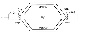
- FIG. 14 is a diagram for explaining linear protection.
- FIG. 14 shows nodes 101 and 102.
- Each of the nodes 101 and 102 has a protection switch unit 101a and 102a.
- the protection switch unit 101a is a bridge, and the protection switch unit 102a is a selector.
- a unique signal number is assigned between nodes, for example, by an operator.
- a signal number Sig1 is assigned between the nodes 101 and 102.
- a path between the active ODU and the backup ODU is established between the nodes 101 and 102, and the protection switch units 101a and 102a switch the path of the client signal at the ODU layer level when a failure occurs.
- the protection switch unit 101a of the node 101 transmits a switching request for the signal number Sig1 with an APS (Automatic Protection Switching) message of the backup ODU in order to request a route switching.
- APS Automatic Protection Switching
- the protection switch unit 102a of the node 102 receives the switching request for the signal number Sig1 through the APS message of the spare ODU, it returns a response to the protection switch unit 101a through the APS message of the spare ODU.
- the protection switch unit 101a can send the client signal to the backup ODU, and the protection switch unit 102a can receive the client signal from the backup ODU. It should be noted that if the signal numbers in linear protection are recognized by the two end nodes, failure switching is possible even if the signal numbers cannot be understood by the relay node.
- Patent Document 1 an add / drop multiplexer capable of supporting fixed-length cells such as ATM (Asynchronous Transfer Mode) cells has been proposed (for example, Patent Document 1).
- an information communication system that does not cause misconnection or traffic drop even when a communication path is set, a monitoring control device used in the information communication system, a transmission device, and a path setting method have been proposed (for example, Patent Document 2). reference).
- OTN is expected to be operated in a ring topology.
- ODU ring protection In 873.2, the study of ODU ring protection has begun.
- a redundant signal number is assigned between nodes in a ring topology, a client signal misconnect occurs when a path is switched due to a failure. there were.
- FIG. 15 is a diagram for explaining misconnection in a ring topology.
- nodes 111 to 116 are shown.
- the solid line double arrow shown in FIG. 15 indicates the working ODU, and the dotted line double arrow indicates the spare ODU. Further, it is assumed that signal numbers Sig1 to Sig6 are assigned between the nodes 111 to 116 as shown in FIG.
- the node 111 transmits, to the node 116, a switching request for the signal number Sig1 where the failure has occurred in the APS message of the spare ODU.
- the node 116 Since the signal number of the traffic to be terminated (received) is “Sig5”, the node 116 passes through the switching request for the signal number Sig1 received by the spare ODU and connects the cross-connect so as to pass through the spare ODU. To do. Similarly, the nodes 115, 114, and 113 pass through.
- the node 112 Since the signal number of the traffic to be terminated is “Sig1”, the node 112 performs switching so as to receive the signal number Sig1 from the spare ODU. When the node 112 receives the APS message for the switching request for the signal number Sig1, the node 112 transmits the response APS message via the nodes 113 to 116 in the spare ODU. As a result, the node 111 can send a client signal to the backup ODU, and the node 112 can receive the client signal from the backup ODU.
- the node 116 terminates the signal number Sig1 received from the node 111 in the spare ODU. End up. For this reason, the client signal to be transmitted from the node 111 to the node 112 in the spare ODU is terminated at the node 116 and misconnected (arrow A101 in FIG. 15). Similarly, the node 115 terminates the signal number Sig1 received from the node 112. For this reason, the client signal to be transmitted from the node 112 to the node 111 in the spare ODU is terminated at the node 115 and misconnected (arrow A102 in FIG. 15).
- This case has been made in view of such points, and an object thereof is to provide a node that can detect a duplicate setting of ring information given between nodes of a ring network.
- nodes forming a ring network are provided.
- the node includes a first receiving unit that receives ring information given between nodes from a first adjacent node, a second receiving unit that receives the ring information from a second adjacent node, and the first receiving unit.
- the ring information received by the receiving unit is added to the second adjacent node with the first self-ring information added between the node and the second adjacent node added to the ring information.
- the ring information in which second ring information given between the node and the first adjacent node is added to the ring information received by the first transmitter and the second receiver.
- a second transmission unit for transmitting to the first adjacent node.
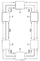
- FIG. 1 is a diagram illustrating a node according to the first embodiment.
- FIG. 1 shows a part of nodes forming a ring network.
- FIG. 1 shows nodes 1, 4, 5, a first adjacent node 2 adjacent to node 1, and a second adjacent node 3 adjacent to node 1.
- Ring information is given by the operator between nodes. For example, as shown in FIG. 1, first self-ring information is given between the node 1 and the second adjacent node 3, and between the node 1 and the first adjacent node 2, Self-ring information of 2 is given. Ring information is also given between the nodes 4 and 5. Also, ring information is given between nodes not shown. The ring information is, for example, a signal number.
- nodes forming a ring network other than the node 1 may be referred to as other nodes.
- the node 1 includes a first receiving unit 1a, a second receiving unit 1b, a first transmitting unit 1c, and a second transmitting unit 1d. Other nodes also have the same reception unit and transmission unit as node 1.
- the first receiving unit 1 a receives ring information from the first adjacent node 2.
- the second reception unit 1 b receives ring information from the second adjacent node 3.
- the first transmitter 1c is a ring in which the first self-ring information given between the node 1 and the second adjacent node 3 is added to the ring information received by the first receiver 1a. Information is transmitted to the second adjacent node 3.
- the second transmitter 1d is a ring in which the second self-ring information given between the node 1 and the first adjacent node 2 is added to the ring information received by the second receiver 1b. Information is transmitted to the first adjacent node 2.
- the other nodes forming the ring network also have the same reception unit and transmission unit as the node 1. Accordingly, the ring information is sequentially added with the own ring information at each node in the clockwise and counterclockwise directions of the ring network. This makes it possible to grasp the status (topology) of ring information given between nodes in the clockwise and counterclockwise directions of the ring network. For example, based on the clockwise and counterclockwise ring information, Duplicate settings can be detected.
- the node 1 receives the ring information from the first adjacent node 2 and the second adjacent node 3, and between the node 1 and the first adjacent node 2 and the second adjacent node 3.
- the attached first self-ring information and second self-ring information are added and transmitted. Thereby, it becomes possible to detect a duplicate setting of ring information given between nodes of the ring network.
- FIG. 2 is a diagram illustrating a ring network to which a node according to the second embodiment is applied.
- the nodes 11 to 16 shown in FIG. 2 form, for example, an OTN ring network.
- unique ring information for distinguishing between the nodes 11 to 16 is given between the nodes 11 to 16 by an operator.
- the ring information is, for example, signal numbers Sig1 to Sig6 as shown in FIG.
- the working ODU route is formed at the ODU layer level as shown by the solid double arrow in FIG. 2, and the backup ODU route is formed as shown by the dotted double arrow.
- the paths of the active ODU and the backup ODU are formed in two optical fibers between nodes, or are formed at different wavelengths in one optical fiber.
- the nodes 11 to 16 transmit and receive the ring information given to their own west side and the east side and collect the ring information given to the ring network before operating the ring network. .
- the nodes 11 to 16 transmit and receive the signal numbers Sig1 to Sig6 assigned to their own West side and East side, and collect information on the signal numbers Sig1 to Sig6 assigned to the ring network.
- the nodes 11 to 16 may transmit and receive the signal numbers Sig1 to Sig6 using the working ODU, and may transmit and receive the signal numbers Sig1 to Sig6 using the spare ODU.
- Nodes 11 to 16 determine whether duplicate ring information has been assigned on the ring network based on the collected information. When duplicate ring information is assigned to the ring network, the nodes 11 to 16 issue an alert or the like to notify the operator or the like that duplicate ring information is assigned. Thereby, it is possible to prevent misconnection of client signals after network operation.
- FIG. 3 is a diagram showing an OTN frame format.
- the digital layer of OTN is basically formed in three layers, and accommodates client signals in ODU via OPU and maps ODU to wavelengths via OTU.
- a region 21 indicated by a thick frame in FIG. 3 indicates the OPU overhead
- a region 22 indicates the ODU overhead
- a region 23 indicates the OTU overhead.
- the client signal is stored in “OPUk Payload” in FIG.
- a reserve area (RES shown in FIG. 3) is prepared by 9 bytes.
- the nodes 11 to 16 transmit and receive ring information using the reserved area. More specifically, ring information is transmitted and received using a 2-byte area 24 shown in FIG.
- the nodes 11 to 16 receive ring information from one adjacent node, add their own ring information (own ring information) to the received ring information, and transmit it to the other adjacent node.
- the nodes 11 to 16 store the ring information in the ‘Ring Info’ area of the area 24 in FIG. 3 and transmit it to the adjacent nodes.
- the ring information transmitted / received between the nodes 11 to 16 has a list structure such as (2, 3, 4, 5, 6, 1), for example.
- the numbers shown in the list structure indicate signal numbers, for example. Since the 'Ring' Info field is a 1-byte fixed-length field, the nodes 11 to 16 transmit ring information one element at a time to adjacent nodes.
- the node 11 when transmitting the above (2, 3, 4, 5, 6, 1) to the node 12, the node 11 transmits the ring information “2” in the “Ring Info” area of a certain frame, and the ring information “ 3 ”is transmitted in the“ Ring Info ”area of the next frame. Similarly, the node 11 sequentially transmits ring information “4” to “1” in different frames.
- the 'Ring Flag' area of the area 24 in Fig. 3 flags indicating the head and tail of ring information transmitted from the nodes 11 to 16 to the adjacent nodes are stored.
- the 'Ring Flag' area has an 8-bit field, and a flag indicating the head and tail of ring information is stored in 2 bits of the field.
- FIG. 4 is a diagram showing the Ring Flag area.
- FIG. 4 shows a 'Ring Flag' region of the region 24 shown in FIG.
- an H flag indicating the head of ring information and a T flag indicating the tail of ring information are stored in the first and second bits of the 'RingRFlag' area.
- the third to eighth bits of 'RingRFlag' are reserved.
- the H flag of “1” is stored in the first bit of the “Ring Flag” area.
- the T flag of “1” is stored in the second bit of the “Ring Flag” area.
- the node 11 sequentially transmits ring information having a list structure of (2, 3, 4, 5, 6, 1) to the node 12.
- the node 11 transmits “2” at the head of the ring information in the “Ring-Info” area
- the node 11 stores an H flag of “1” in the “Ring-Flag” area.
- the node 11 transmits “1” at the end of the ring information in the “Ring-Info” area
- the node 11 stores a T flag of “1” in the “Ring-Flag” area.
- the node 11 stores the H flag and the T flag of ‘0’.
- FIG. 5 is a diagram for explaining the ring information, the H flag, and the T flag.
- the H and T columns of flag shown in FIG. 5 the states of the H flag and the T flag are shown.
- the Info column ring information transmitted from the node 11 to the node 12 is shown. Assume that the node 11 transmits ring information of the ring structure (2, 3, 4, 5, 6, 1) to the node 12.
- the node 11 sets the H flag to ‘1’ when transmitting the first ring information ‘1’.
- the node 11 sets the H flag and the T flag to ‘0’ when transmitting ring information ‘3, 4, 5, 6’ on the way.
- the node 11 sets the T flag to ‘1’ when transmitting the last ring information ‘1’.
- the node 12 can appropriately receive the ring information of (2, 3, 4, 5, 6, 1) of the list structure from the node 11.
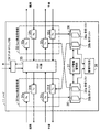
- FIG. 6 is a block diagram of the node.
- the node 11 includes a West-side transmission / reception unit 31, an East-side transmission / reception unit 32, an ODUXC unit (ODU cross-connect unit) 33, an add / drop unit 34, ring map tables 35 and 36, and a ring information management unit. 37 and an overlap determination unit 38.
- the other nodes 12 to 16 that form the ring network also have the same blocks as the node 11, and the description thereof is omitted.
- the West transmission / reception unit 31 and the East transmission / reception unit 32 perform ODU termination processing on the West side and the East side of the node 11, respectively.
- the node 16 shown in FIG. 2 is connected to the West side
- the node 12 is connected to the East side.
- the West-side transmitting / receiving unit 31 has an active Rx (receiving unit) 31a and Tx (transmitting unit) 31b, and has spare Rx 31c and Tx 31d.
- the East-side transmitting / receiving unit 32 has working Tx32a and Rx32b, and has spare Tx32c and Rx32d.
- the Rx 31a, 31c, 32b, and 32d and the Tx 31b, 31d, 32a, and 32c perform ODU termination processing of signals that are transmitted to and received from adjacent nodes.
- the Rx 31c When the Rx 31c receives the frame having the H flag indicating the head of the ring information, the Rx 31c extracts the ring information from the Ring Info area of the frame and stores it in the reception list 35a. The Rx 31c extracts the ring information from the Ring Info area of the frame until it receives the frame having the T flag indicating the tail of the ring information, and sequentially stores it in the reception list 35a.
- Rx32d When Rx32d receives the frame having the H flag indicating the head of the ring information, it extracts the ring information from the Ring Info area of the frame and stores it in the reception list 36a. The Rx 32d extracts the ring information from the Ring Info area of the frame until it receives the frame having the T flag indicating the tail of the ring information, and sequentially stores it in the reception list 36a.
- Tx 31d outputs the ring information stored in the save list 36b to the West side.
- the OTN is a synchronous network, and continues to transmit frames continuously.
- the Tx 31d sequentially transmits ring information with the overhead of the frames transmitted continuously.
- Tx32c outputs the ring information stored in the save list 35b to the West side.
- OTN is a synchronous network, and continues to transmit frames continuously, and Tx32c sequentially transmits ring information with the overhead of the frames transmitted continuously.
- the ODUXC unit 33 performs ODU cross-connect.
- the ODUXC unit 33 outputs the ODU to be dropped to the add / drop unit 34, and outputs the ODU to be added from the add / drop unit 34 to the West side transceiver unit 31 or the East side transceiver unit 32.
- the add / drop unit 34 receives a signal to be added from a low-order network node and outputs the signal to the ODUXC unit 33. Further, the add / drop unit 34 receives a signal to be dropped from the ODUXC unit 33 and outputs the signal to a low-order network node.
- the ring map tables 35 and 36 are provided on the West side and the East side, respectively.
- the ring map table 35 has a reception list 35a and a storage list 35b
- the ring map table 36 has a reception list 36a and a storage list 36b.
- the ring information management unit 37 includes self-ring information (hereinafter also referred to as East-side self-ring information) provided between the node 11 and the adjacent node 12 connected to the East side in the reception list 35a. Judge whether it is. When the reception list 35a does not include the own ring information on the East side, the ring information management unit 37 adds the own ring information on the East side to the ring information stored in the reception list 35a and stores it in the save list 35b. To do.
- self-ring information hereinafter also referred to as East-side self-ring information
- the ring information management unit 37 includes ring information (hereinafter also referred to as “West-side self-ring information”) given to the reception list 36a between the node 11 and the adjacent node 16 connected to the West side. Determine if it is included. If the reception list 36a does not include the own ring information on the West side, the ring information management unit 37 adds the own ring information on the West side to the ring information stored in the reception list 36a and stores it in the save list 36b. To do.
- ring information hereinafter also referred to as “West-side self-ring information”
- the duplication determination unit 38 compares the save list 35b with the save list 36b. If the ring information stored in the save list 35b and the save list 36b is different, the duplication determination unit 38 determines that duplicate ring information is set in the ring network, and issues an alert or the like, for example.
- FIG. 6 is a diagram for explaining transmission / reception of ring information.
- nodes 11 to 16 are shown.
- Signal numbers Sig1 to Sig6 are assigned between the nodes 11 to 16, as shown in FIG.
- the numbers in the squares shown in FIG. 7 indicate the signal numbers transmitted to the adjacent nodes.
- Each of the nodes 11 to 16 stores the signal number assigned to the adjacent node on the East side in the save list of the ring map table on the West side as an initial setting. Further, each of the nodes 11 to 16 stores the signal number assigned to the adjacent node on the West side in the saving list of the ring map table on the East side.
- the left side of each of the nodes 11 to 16 is the West side, and the right side is the East side.
- the signal number Sig5 is stored as an initial setting in the save list of the ring map table on the West side of the node 15.
- the signal number Sig4 is stored as an initial setting.
- the node 15 transmits the signal number Sig5 stored in the saving list on the West side to the node 16.
- the node 16 transmits the received signal number Sig5 to the node 11, and then transmits the signal number Sig6 which is self-ring information on the East side.
- the node 16 transmits an H flag indicating that it is the first signal number, and when transmitting the signal number Sig6, the node 16 indicates a T flag indicating that it is the last signal number.
- Send
- Node 11 receives signal numbers Sig5 and Sig6 based on the H flag and T flag from node 16.
- the node 11 transmits the received signal numbers Sig5 and Sig6 and the signal number Sig1 which is self-ring information on the East side.
- the node 11 transmits an H flag indicating that it is the first signal number, and when transmitting the signal number Sig1, it indicates a T flag indicating that it is the last signal number.
- the nodes 12 to 14 transmit signal numbers to the adjacent nodes 13 to 15.
- the node 15 transmits the signal number Sig4 to the West side in the same manner before the network operation after power-on. That is, the nodes 11 to 16 perform transmission / reception of signal numbers similar to the above even in the clockwise direction of FIG.
- the other nodes 11 to 14 and 16 also transmit the initially set signal numbers to the adjacent nodes on the East side and the West side after the power is turned on and before the network operation.
- the adjacent node adds its own signal number to the received signal number, and further transmits to the adjacent node.
- FIG. 8 is a flowchart showing node reception processing. Below, the reception process of the node 11 is demonstrated. The other nodes 12 to 16 perform similar reception processing. [Step S1] The Rx 31c receives an OTN frame from the West-side node 16.
- Step S2 The Rx 31c determines whether or not the H flag is included in the Ring Flag area of the received frame. When the H flag is included in the Ring Flag area of the received frame, the Rx 31c proceeds to step S3. If the H flag is not included in the Ring Flag area of the received frame, the Rx 31c proceeds to step S4.
- Step S3 The Rx 31c initializes the reception list 35a of the ring map table 35 on the West side. For example, Rx 31c writes “0” in the reception list 35a.
- Step S4 The Rx 31c writes the ring information included in the Ring Info area of the received frame to the reception list 35a.
- Step S5 The Rx 31c determines whether or not the T flag is included in the Ring Flag area of the received frame. When the T flag is included in the Ring Flag area of the received frame, the Rx 31c proceeds to step S6. If the T flag is not included in the Ring Flag area of the received frame, the Rx 31c proceeds to step S1.
- the Rx 31c when the T flag is included in the Ring Flag area of the received frame, the Rx 31c has received all the ring information to be received (ring information list), and thus proceeds to the next step S6. On the other hand, when the T flag is not included in the Ring Flag area of the received frame, the Rx 31c returns to step S1 because it has not received all the ring information to be received.
- Step S6 The ring information management unit 37 proceeds to a list update process described below.
- the node 11 receives ring information to be received from the adjacent node, that is, a list of ring information, by the H flag and the T flag.
- the Rx 31c on the West side has been described, but the Rx 32d on the East side similarly performs ring information reception processing.
- the spare Rx 31c has been described, but the ring information may be received by the active Rx 31a.
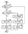
- FIG. 9 is a flowchart showing node update processing. Below, the reception process of the node 11 is demonstrated. The other nodes 12 to 16 perform the same update process. [Step S21] The ring information management unit 37 compares the list of ring information stored in the save list 35b with the list of ring information stored in the reception list 35a, and if the comparison results do not match, Proceed to step S22. If the comparison results match, the ring information management unit 37 proceeds to step S25.
- Step S22 The ring information management unit 37 determines whether or not the East-side self-ring information is included in the reception list 35a. That is, the ring information management unit 37 determines whether or not the reception list 35a includes ring information provided between adjacent nodes connected to the East side. When the reception list 35a includes the own ring information on the East side, the ring information management unit 37 proceeds to step S26. If the reception list 35a does not include the east-side self-ring information, the ring information management unit 37 proceeds to step S23.
- the ring information management unit 37 adds the own ring information on the East side to the list of ring information stored in the reception list 35a.
- the ring information management unit 37 stores a list of ring information to which the east-side own ring information is added in the save list 35b, and updates the save list 35b.
- Step S25 The node 11 proceeds to step S1 of the reception process described in FIG.
- Step S26 The ring information management unit 37 stores the ring information stored in the reception list 35a in the storage list 35b, and updates the storage list 35b.
- Step S27 The ring information management unit 37 proceeds to the duplication determination process described below.
- the node 11 determines whether or not the received ring information includes the own ring information.
- the node 11 adds the own ring information to the ring information received from the adjacent node, and stores it in the save list 35b.
- the ring information written in the save list 35b is provided with an H flag and a T flag, and is output to the adjacent node on the West side by Tx32c.
- step S21 the storage list 35b and the reception list 35a are the same when the same list of ring information is continuously received from adjacent nodes. If there is no change in the reception list 35a and the storage list 35b, the update of the new storage list 35b and the duplication determination process are unnecessary. In this case, the ring information management unit 37 returns to the reception process described with reference to FIG.
- the West-side ring map table 35 has been described, but the East-side ring map table 36 is similarly updated with the reception list 36a and the save list 36b.
- the node 11 when duplicate ring information is assigned to the ring network, the node 11 has its own ring information in the reception list 35a in step S22 before receiving all the ring information. to decide. In this case, the contents of the clockwise ring information and the counterclockwise ring information (saved list 35b, 36b) are different. Therefore, by comparing the contents of the save lists 35b and 36b, it is possible to determine whether or not the ring information of the ring network is duplicated.
- FIG. 10 is a flowchart showing node duplication determination processing. Below, the reception process of the node 11 is demonstrated. The other nodes 12 to 16 perform the same duplication determination process.
- the duplication determination unit 38 sorts the arrangement of the ring information of one of the save list 35b and the save list 36b in reverse order. For example, when the ring information of (1, 2, 3, 4, 5, 6) is stored in the save list 35b, the duplication determination unit 38 is in the order of (6, 5, 4, 3, 2, 1). Sort in reverse. This is because the save information is stored in the save lists 35b and 36b in the reverse order of the ring information clockwise and counterclockwise.
- the duplication determination unit 38 sorts the ring information in the save list 35b in reverse order.
- Step S32 The duplication determination unit 38 compares the saved list 35b and the saved list 36b in which the ring information is sorted in the reverse order. The duplication determination unit 38 proceeds to step S34 when the comparison results match, that is, when duplicate ring information is not assigned to the ring network. If the comparison results do not match, that is, if duplicate ring information is assigned to the ring network, the process proceeds to step S33.
- the duplication determination unit 38 performs alert processing. For example, the duplication determination unit 38 generates a warning sound.
- Step S34 The duplication determination unit 38 proceeds to step S1 of the reception process described in FIG.
- the ring information in the save lists 35b and 36b does not match, and the node 11 can issue an alert.
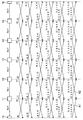
- FIG. 11 is a diagram showing transmission / reception of ring information when ring information is uniquely assigned to the ring network.
- FIG. 11 shows the nodes 11 to 16 shown in FIG. Further, it is assumed that signal numbers Sig1 to Sig6, which are ring information, are assigned between the nodes 11 to 16, as shown in FIG. In FIG. 11, in order to indicate that it is a ring network, the node 16 is divided into two for convenience, but is actually one.
- the numbers in parentheses on the right side of the dotted line shown in FIG. 11 indicate the ring information transmitted from the nodes 11 to 16 counterclockwise.
- the numbers in parentheses shown on the left side indicate ring information that the nodes 11 to 16 transmit clockwise.
- the nodes 11 to 16 add their own ring information to the ring information received from one adjacent node, and transmit the ring information to the other adjacent node.
- the nodes 11 to 16 update the storage lists 35b and 36b and proceed to duplication determination. For example, when the node 11 receives the ring information indicated by the arrows A1 and A2 in FIG. 11 and stores the ring information in the reception lists 35a and 36a, the node 11 updates the save lists 35b and 36b and proceeds to duplication determination.
- Node 11 sorts the ring information received at arrow A1, and compares it with the ring information received at arrow A2.
- the ring information indicated by the arrow A1 becomes (6, 5, 4, 3, 2, 1) by sorting and matches the ring information received by the arrow A2.
- the ring information received clockwise and counterclockwise also matches in the other nodes 12-16. As a result, no alert is generated in the nodes 11-16.
- FIG. 12 is a diagram showing transmission / reception of ring information when duplicate ring information is assigned to the ring network.
- the same reference numerals are given to the same components as those in FIG. In FIG. 12, the same signal number Sig1 as that of the nodes 11 and 12 is assigned between the nodes 15 and 16 with respect to FIG.
- the node 11 When duplicate ring information is given as shown in FIG. 12, the node 11 receives its own ring information (in this case, signal number Sig1) before receiving all the ring information, for example, as indicated by an arrow A11. The included ring information is received from the node 16.
- signal number Sig1 in this case, signal number Sig1
- the node 11 proceeds to step S26 based on the determination in step S22 described with reference to FIG. That is, the node 11 updates the storage list 35b without adding its own ring information to the received ring information, and proceeds to duplication determination. The node 11 generates an alert because the ring information in the save lists 35b and 36b does not match. Further, since the save list 35b is updated without adding own ring information, the node 11 transmits the ring information (1, 6) to the adjacent node 12 as indicated by an arrow A12. Furthermore, the node 11 continues to receive ring information including its own ring information and generates an alert until it is stopped by an operator or the like, for example.
- the nodes 11 to 16 receive the ring information from the adjacent nodes 11 to 16, add their own ring information, and transmit them to the adjacent nodes. As a result, the nodes 11 to 16 can detect the duplication setting of the ring information given between the nodes of the ring network.
- the signal number is taken as an example of ring information, but ring information can also be generated from a node ID (Identify).
- Identify a node ID
- the ring information on the east side of each of the nodes 11 to 16 is set as a node ID. More specifically, the ring information between the node 11 and the node 12 is the node ID of the node 11, and the ring information between the node 12 and the node 13 is the node ID of the node 12.
- all nodes forming the ring network independently transmit and receive ring information and detect duplication of ring information.
- one of the nodes forming the ring network is a master node, and the master node detects the duplication of ring information.
- FIG. 13 is a diagram showing transmission / reception of ring information by the master node according to the third embodiment.
- the functional blocks of the node according to the third embodiment are the same as those in FIG. 6, but only the master node transmits its own ring information to the adjacent node before the ring network is operated, and nodes other than the master node are adjacent to each other. The difference is that the own ring information is added to the ring information received from the node and transmitted.
- the third embodiment is different in that only the master node determines duplication. That is, the nodes other than the master node perform the reception process of FIG. 8 and the processes of steps S21 and S23 to S25 of FIG. 9 are different. Also, the master node performs the duplication determination process according to the second embodiment, and performs the duplication determination of the ring information depending on the presence / absence of ring information duplicated in the ring information received from the clockwise and counterclockwise directions.
- the node 11 is a master node.
- the master node is selected by an operator, for example. Further, it is assumed that signal numbers Sig1 to Sig6, which are ring information, are assigned between the nodes 11 to 16, as shown in FIG.
- the node 11 that is the master node transmits its own ring information clockwise and counterclockwise. For example, as illustrated in FIG. 13, the node 11 transmits the signal number Sig6 clockwise and transmits the signal number Sig1 counterclockwise.
- nodes 12 to 16 other than the master node When nodes 12 to 16 other than the master node receive ring information from one adjacent node, they add their own ring information and transmit the ring information to the other adjacent node. As a result, the master node receives the list of ring information that has made one round of the ring network from the clockwise and counterclockwise directions. For example, as shown in FIG. 13, the node 11 receives the ring information (6, 1, 4, 3, 2, 1) in the clockwise direction and (1, 2, 3, 4, 1, 2) in the counterclockwise direction. 6) is received.
- Node 11 determines whether there is duplicate ring information in the received ring information. In the example of FIG. 13, since “1” is duplicated in both the clockwise and counterclockwise ring information lists, the node 11 determines that the ring information is duplicated.
- the master node transmits ring information, and the other nodes add their own ring information to the received ring information and transmit it to the adjacent node.
- the master node can detect the duplication of ring information based on the list contents of the ring information circulating through the ring network.
- the master node transmits the ring information in both the clockwise and counterclockwise directions.
- the master node may transmit the ring information only in one direction.
- the node 12 receives the signal numbers Sig1 to Sig6 given between the nodes 11 to 16 from the adjacent node 11, and the signal numbers Sig1 to Sig6 received by the reception unit to the node 12 and the adjacent node 13 And a transmitter that transmits to the adjacent node 13 ring information to which the signal number Sig2 of the self-ring information given between and is added. The same applies to the other nodes 11 to 16.
Landscapes
- Engineering & Computer Science (AREA)
- Computer Networks & Wireless Communication (AREA)
- Signal Processing (AREA)
- Small-Scale Networks (AREA)
Abstract
リングネットワークのノード間に付与されたリング情報の重複設定を検出することができるようになる。 第1の受信部(1a)は、第1の隣接ノード(2)からリング情報を受信する。第2の受信部(1b)は、第2の隣接ノード(3)からリング情報を受信する。第1の送信部(1c)は、第1の受信部(1a)によって受信されたリング情報に当該ノード(1)と第2の隣接ノード(3)との間に付与された第1の自リング情報が付加されたリング情報を第2の隣接ノード(3)に送信する。第2の送信部(1d)は、第2の受信部(1b)によって受信されたリング情報に当該ノード(1)と第1の隣接ノード(2)との間に付与された第2の自リング情報が付加されたリング情報を第1の隣接ノード(2)に送信する。
Description
本件は、リングネットワークを形成するノードおよびそのノードのリング情報送信方法に関する。
OTN(Optical Transport Network)は、SONET/SDH(Synchronous Optical Network / Synchronous Digital Hierarchy)をベースにした高速伝送技術であり、SONET/SDHやイーサネット(登録商標)系のサービスを収容できるように設計されている。フレーム構造は、ITU-T(International Telecommunication Union Telecommunication Standardization Sector)においてG.709にて規定され、オーバヘッドはSONET/SDHに似た形となっている。OTNのデジタルレイヤは、基本的に3階層で形成されており、クライアント信号をOPU(Optical channel Payload Unit)経由でODU(Optical channel Data Unit)へ収容し、それをOTU(Optical channel Transport Unit)を経由して波長にマッピングする。
ネットワークでは運営上、障害に備えたプロテクション技術が必須となっている。OTNにおいても、ITU-TのG.873.1においてリニアプロテクションが規定されている。
図14は、リニアプロテクションを説明する図である。図14には、ノード101,102が示してある。ノード101,102のそれぞれは、プロテクションスイッチ部101a,102aを有している。プロテクションスイッチ部101aはブリッジ、プロテクションスイッチ部102aはセレクタとする。
ノード間には、例えば、オペレータによって、一意のシグナル番号が付与される。例えば、図14の場合、ノード101,102間には、シグナル番号Sig1が付与されている。
図14では、ノード101,102の間に、現用ODUと予備ODUの経路が張られ、プロテクションスイッチ部101a,102aは、障害が発生したとき、ODUレイヤレベルでクライアント信号の経路切り替えを行う。
例えば、現用ODUにて障害が発生した場合、ノード101のプロテクションスイッチ部101aは、経路の切り替えを要求するために、予備ODUのAPS(Automatic Protection Switching)メッセージにてシグナル番号Sig1に対する切り替え要求を送信する。ノード102のプロテクションスイッチ部102aは、予備ODUのAPSメッセージにてシグナル番号Sig1に対する切り替え要求を受信すると、その応答を予備ODUのAPSメッセージにてプロテクションスイッチ部101aに返す。
これにより、プロテクションスイッチ部101aは、クライアント信号を予備ODUに送出でき、プロテクションスイッチ部102aは、予備ODUからクライアント信号を受信することができる。なお、リニアプロテクションにおけるシグナル番号は、2つの両端ノードで認識が一致していれば、中継ノードで理解できなくても障害切り替えが可能である。
なお、従来、既存のサービス(DS1,DS3,STS-1等)に加えて、ATM(Asynchronous Transfer Mode)セル等の固定長セルに対応できるアド・ドロップ多重化装置が提案されている(例えば、特許文献1参照)。また、通信パスの設定時にもミスコネクトやトラフィックの落ちが発生しない情報通信システム、この情報通信システムで使用される監視制御装置、伝送装置およびパス設定方法が提案されている(例えば、特許文献2参照)。
OTNは、リングトポロジでの運用も想定され、ITU-TのG.873.2では、ODUリングプロテクションの検討が始まっている。リニアプロテクションと同様のAPSメッセージを使用すると、リングトポロジにおいて、ノード間に重複したシグナル番号が付与されると、障害発生による経路切り替えが行われた場合、クライアント信号のミスコネクトが生じるという問題点があった。
図15は、リングトポロジでのミスコネクトを説明する図である。図15には、ノード111~116が示してある。図15に示す実線両矢印は現用ODUを示し、点線両矢印は予備ODUを示している。また、各ノード111~116間には、図15に示すようにシグナル番号Sig1~Sig6が付与されているとする。
ここで、ノード111,112間の現用ODUおよび予備ODUに障害が発生したとする。この場合、ノード111は、ノード116に対し、予備ODUのAPSメッセージにて障害の発生したシグナル番号Sig1に対する切り替え要求を送信する。
ノード116は、自分の終端(受信)すべきトラフィックのシグナル番号は‘Sig5’であるため、予備ODUにて受信したシグナル番号Sig1に対する切り替え要求をパススルーし、予備ODUをパススルーするようクロスコネクトを接続する。ノード115,114,113も同様にパススルーする。
ノード112は、自分の終端すべきトラフィックのシグナル番号は‘Sig1’であるため、予備ODUからシグナル番号Sig1を受信するように切り替えを行う。ノード112は、シグナル番号Sig1に対する切り替え要求のAPSメッセージを受信すると、その応答APSメッセージを予備ODUにて、ノード113~116を経由して送信する。これにより、ノード111は、クライアント信号を予備ODUに送出でき、ノード112は、予備ODUからクライアント信号を受信することができる。
上記は、オペレータによってシグナル番号が一意に割り当てられた場合である。これに対し、オペレータが、例えば、ノード115,116間にシグナル番号Sig1(図15中のかっこ書き)を付与した場合、ノード116は、予備ODUにてノード111から受信したシグナル番号Sig1を終端してしまう。このため、予備ODUにてノード111からノード112に送信されるべきクライアント信号は、ノード116で終端され、ミスコネクトとなってしまう(図15の矢印A101)。同様に、ノード115は、ノード112から受信したシグナル番号Sig1を終端してしまう。このため、予備ODUにてノード112からノード111に送信されるべきクライアント信号は、ノード115で終端され、ミスコネクトとなってしまう(図15の矢印A102)。
本件はこのような点に鑑みてなされたものであり、リングネットワークのノード間に付与されるリング情報の重複設定を検出することができるようになるノードを提供することを目的とする。
上記課題を解決するために、リングネットワークを形成するノードが提供される。このノードは、第1の隣接ノードからノード間に付与されたリング情報を受信する第1の受信部と、第2の隣接ノードから前記リング情報を受信する第2の受信部と、前記第1の受信部によって受信された前記リング情報に当該ノードと前記第2の隣接ノードとの間に付与された第1の自リング情報が付加された前記リング情報を前記第2の隣接ノードに送信する第1の送信部と、前記第2の受信部によって受信された前記リング情報に当該ノードと前記第1の隣接ノードとの間に付与された第2の自リング情報が付加された前記リング情報を前記第1の隣接ノードに送信する第2の送信部と、を有する。
開示のノードおよびリング情報送信方法によれば、リングネットワークのノード間に付与されたリング情報の重複設定を検出することができるようになる。
本発明の上記および他の目的、特徴および利点は本発明の例として好ましい実施の形態を表す添付の図面と関連した以下の説明により明らかになるであろう。
本発明の上記および他の目的、特徴および利点は本発明の例として好ましい実施の形態を表す添付の図面と関連した以下の説明により明らかになるであろう。
以下、第1の実施の形態を、図面を参照して詳細に説明する。
図1は、第1の実施の形態に係るノードを示した図である。図1には、リングネットワークを形成しているノードの一部が示してある。図1には、ノード1,4,5と、ノード1に隣接する第1の隣接ノード2と、ノード1に隣接する第2の隣接ノード3とが示してある。
図1は、第1の実施の形態に係るノードを示した図である。図1には、リングネットワークを形成しているノードの一部が示してある。図1には、ノード1,4,5と、ノード1に隣接する第1の隣接ノード2と、ノード1に隣接する第2の隣接ノード3とが示してある。
ノードの間には、オペレータによってリング情報が付与されている。例えば、図1に示すように、ノード1と第2の隣接ノード3との間には、第1の自リング情報が付与され、ノード1と第1の隣接ノード2との間には、第2の自リング情報が付与されている。また、ノード4,5の間にもリング情報が付与されている。また、図示していないノード間にもリング情報が付与されている。リング情報は、例えば、シグナル番号である。以下では、ノード1以外のリングネットワークを形成しているノードを他のノードと呼ぶことがある。
ノード1は、第1の受信部1a、第2の受信部1b、第1の送信部1c、および第2の送信部1dを有している。他のノードもノード1と同様の受信部および送信部を有している。
第1の受信部1aは、第1の隣接ノード2からリング情報を受信する。
第2の受信部1bは、第2の隣接ノード3からリング情報を受信する。
第1の送信部1cは、第1の受信部1aによって受信されたリング情報に、当該ノード1と第2の隣接ノード3との間に付与された第1の自リング情報が付加されたリング情報を第2の隣接ノード3に送信する。
第2の受信部1bは、第2の隣接ノード3からリング情報を受信する。
第1の送信部1cは、第1の受信部1aによって受信されたリング情報に、当該ノード1と第2の隣接ノード3との間に付与された第1の自リング情報が付加されたリング情報を第2の隣接ノード3に送信する。
第2の送信部1dは、第2の受信部1bによって受信されたリング情報に、当該ノード1と第1の隣接ノード2との間に付与された第2の自リング情報が付加されたリング情報を第1の隣接ノード2に送信する。
上記したようにリングネットワークを形成している他のノードも、ノード1と同様の受信部および送信部を有している。従って、リング情報は、リングネットワークの右回りおよび左回りにおいて、各ノードにおける自リング情報が順次追加されていく。これにより、リングネットワークの右回りおよび左回りにおけるノード間に付与されたリング情報の状況(トポロジ)を把握することが可能となり、例えば、右回りと左回りのリング情報に基づいて、リング情報の重複設定を検出することが可能となる。
このように、ノード1は、第1の隣接ノード2および第2の隣接ノード3からリング情報を受信し、当該ノード1と、第1の隣接ノード2および第2の隣接ノード3との間に付与された第1の自リング情報および第2の自リング情報を付加して送信するようにした。これにより、リングネットワークのノード間に付与されたリング情報の重複設定を検出することができるようになる。
次に、第2の実施の形態を、図面を参照して詳細に説明する。
図2は、第2の実施の形態に係るノードを適用したリングネットワークを示した図である。図2に示すノード11~16は、例えば、OTNのリングネットワークを形成している。ノード11~16間には、例えば、オペレータによって、ノード11~16間を区別するための一意のリング情報が付与される。リング情報は、例えば、図2に示すようにシグナル番号Sig1~Sig6である。
図2は、第2の実施の形態に係るノードを適用したリングネットワークを示した図である。図2に示すノード11~16は、例えば、OTNのリングネットワークを形成している。ノード11~16間には、例えば、オペレータによって、ノード11~16間を区別するための一意のリング情報が付与される。リング情報は、例えば、図2に示すようにシグナル番号Sig1~Sig6である。
OTNのリングネットワークでは、図2の実線両矢印に示すようにODUレイヤレベルで現用ODUの経路が形成され、また、点線両矢印に示すように予備ODUの経路が形成される。現用ODUと予備ODUの経路は、例えば、ノード間の2本の光ファイバにそれぞれ形成され、または、1本の光ファイバにおいて異なる波長で形成される。
ノード11~16は、後述するように、例えば、リングネットワークの運用前に、自分のWest側およびEast側に付与されたリング情報の送受信を行って、リングネットワークに付与されたリング情報を収集する。例えば、ノード11~16は、自分のWest側およびEast側に付与されたシグナル番号Sig1~Sig6の送受信を行って、リングネットワークに付与されたシグナル番号Sig1~Sig6の情報を収集する。ノード11~16は、現用ODUを用いてシグナル番号Sig1~Sig6を送受信してもよいし、予備ODUを用いてシグナル番号Sig1~Sig6を送受信してもよい。
ノード11~16は、収集した情報に基づいてリングネットワーク上に重複したリング情報が付与されていないか判定する。ノード11~16は、リングネットワークに重複したリング情報が付与されている場合、例えば、アラート等を発して、オペレータ等に重複したリング情報が付与されていることを通知する。これにより、ネットワーク運用後のクライアント信号のミスコネクトを防止することができる。
図3は、OTNのフレームフォーマットを示した図である。OTNのデジタルレイヤは、基本的に3階層で形成されており、クライアント信号をOPU経由でODUへ収容し、ODUをOTUを経由して波長にマッピングする。図3の太枠で示す領域21はOPUのオーバヘッドを示し、領域22はODUのオーバヘッドを示し、領域23はOTUのオーバヘッドを示す。クライアント信号は、図3の‘OPUk Payload’に格納される。
OTNフレームのODUオーバヘッドでは、リザーブ領域(図3に示すRES)が9バイト用意されている。ノード11~16は、例えば、そのリザーブ領域を用いて、リング情報の送受信を行う。より具体的には、図3に示す2バイトの領域24を用いてリング情報の送受信を行う。
ノード11~16は、後述するように、一方の隣接ノードからリング情報を受信し、受信したリング情報に自分のリング情報(自リング情報)を追加して、他方の隣接ノードに送信する。ノード11~16は、図3の領域24の‘Ring Info’領域にリング情報を格納して隣接ノードに送信する。
ノード11~16間で送受信するリング情報は、例えば、(2,3,4,5,6,1)のようなリスト構造を有している。前記のリスト構造に示す数字は、例えば、シグナル番号を示している。‘Ring Info’領域は、1バイトの固定長フィールドなので、ノード11~16は、リング情報を1要素ずつ順に隣接ノードへ送信する。
例えば、ノード11は、上記の(2,3,4,5,6,1)をノード12に送信する場合、リング情報‘2’をあるフレームの‘Ring Info’領域で送信し、リング情報‘3’を次のフレームの‘Ring Info’領域で送信する。以下同様に、ノード11は、リング情報‘4’~‘1’を異なるフレームで順次送信する。
図3の領域24の‘Ring Flag’領域には、ノード11~16が隣接ノードに送信するリング情報の先頭と最後尾を示すフラグが格納される。例えば、‘Ring Flag’領域は、8ビットのフィールドを有し、そのうちの2ビットにリング情報の先頭と最後尾を示すフラグが格納される。
図4は、Ring Flag領域を示した図である。図4には、図3で示した領域24の‘Ring Flag’領域が示してある。図4に示すように‘Ring Flag’領域の1ビット目と2ビット目には、リング情報の先頭を示すHフラグとリング情報の最後尾を示すTフラグが格納される。‘Ring Flag’の3ビット目から8ビット目はリザーブである。
ノード11~16は、リング情報の先頭を送信するとき、例えば、‘Ring Flag’領域の1ビット目に‘1’のHフラグを格納する。また、ノード11~16は、リング情報の最後尾を送信するとき、例えば、‘Ring Flag’領域の2ビット目に‘1’のTフラグを格納する。途中のリング情報を送信するときには、‘0’のHフラグおよびTフラグを格納する。
例えば、ノード11は、(2,3,4,5,6,1)のリスト構造のリング情報を順にノード12に送信するとする。この場合、ノード11は、リング情報の先頭の‘2’を‘Ring Info’領域で送信するとき、‘Ring Flag’領域に‘1’のHフラグを格納する。また、ノード11は、リング情報の最後尾の‘1’を‘Ring Info’領域で送信するとき、‘Ring Flag’領域に‘1’のTフラグを格納する。途中の‘3,4,5,6’を送信するときは、ノード11は、‘0’のHフラグおよびTフラグを格納する。
図5は、リング情報、Hフラグ、およびTフラグを説明する図である。図5に示すflagのHおよびTの欄には、HフラグおよびTフラグの状態が示してある。Infoの欄には、ノード11がノード12に送信するリング情報が示してある。ノード11は、ノード12にリング構造(2,3,4,5,6,1)のリング情報をノード12に送信するとする。
図5に示すように、ノード11は、先頭のリング情報‘1’を送信するとき、Hフラグを‘1’にする。ノード11は、途中のリング情報‘3,4,5,6’を送信するとき、HフラグおよびTフラグを‘0’にする。ノード11は、最後尾のリング情報‘1’を送信するとき、Tフラグを‘1’にする。これにより、ノード12は、ノード11からリスト構造の(2,3,4,5,6,1)のリング情報を適切に受信することができる。
図6は、ノードのブロック図である。図6に示すように、ノード11は、West側送受信部31、East側送受信部32、ODUXC部(ODUクロスコネクト部)33、アッド・ドロップ部34、リングマップテーブル35,36、リング情報管理部37、および重複判定部38を有している。なお、リングネットワークを形成する他のノード12~16もノード11と同様のブロックを有しており、その説明は省略する。
West側送受信部31およびEast側送受信部32は、ノード11のWest側およびEast側のそれぞれにおいてODU終端処理を行う。West側には、例えば、図2で示したノード16が接続され、East側には、ノード12が接続されている。
West側送受信部31は、現用のRx(受信部)31aおよびTx(送信部)31bを有し、また、予備のRx31cおよびTx31dを有している。East側送受信部32は、現用のTx32aおよびRx32bを有し、また、予備のTx32cおよびRx32dを有している。Rx31a,31c,32b,32dおよびTx31b,31d,32a,32cは、隣接するノードと送受信する信号のODU終端処理を行う。
Rx31cは、リング情報の先頭を示すHフラグを有するフレームを受信すると、そのフレームのRing Info領域からリング情報を抽出し、受信リスト35aに記憶する。Rx31cは、リング情報の最後尾を示すTフラグを有するフレームを受信するまで、フレームのRing Info領域からリング情報を抽出し、順次受信リスト35aに記憶する。
Rx32dは、リング情報の先頭を示すHフラグを有するフレームを受信すると、そのフレームのRing Info領域からリング情報を抽出し、受信リスト36aに記憶する。Rx32dは、リング情報の最後尾を示すTフラグを有するフレームを受信するまで、フレームのRing Info領域からリング情報を抽出し、順次受信リスト36aに記憶する。
Tx31dは、保存リスト36bに記憶されているリング情報をWest側に出力する。OTNは同期網であり、フレームを連続して送信し続け、Tx31dは連続して送信されるそのフレームのオーバヘッドでリング情報を順次送信する。
Tx32cは、保存リスト35bに記憶されているリング情報をWest側に出力する。OTNは同期網であり、フレームを連続して送信し続け、Tx32cは連続して送信されるそのフレームのオーバヘッドでリング情報を順次送信する。
ODUXC部33は、ODUのクロスコネクトを行う。ODUXC部33は、ドロップするODUをアッド・ドロップ部34へ出力し、アッド・ドロップ部34からのアッドするODUをWest側送受信部31またはEast側送受信部32へ出力する。
アッド・ドロップ部34は、低次のネットワークノードからアッドする信号を受信し、ODUXC部33に出力する。また、アッド・ドロップ部34は、ドロップする信号をODUXC部33から受信し、低次のネットワークノードに出力する。
リングマップテーブル35,36は、それぞれWest側とEast側に設けられている。リングマップテーブル35は、受信リスト35aおよび保存リスト35bを有し、リングマップテーブル36は、受信リスト36aおよび保存リスト36bを有している。
リング情報管理部37は、受信リスト35aにノード11とEast側に接続された隣接ノード12との間に付与された自リング情報(以下ではEast側の自リング情報と呼ぶこともある)が含まれているか判断する。リング情報管理部37は、受信リスト35aにEast側の自リング情報が含まれていない場合、受信リスト35aに記憶されているリング情報にEast側の自リング情報を追加して保存リスト35bに記憶する。
また、リング情報管理部37は、受信リスト36aにノード11とWest側に接続された隣接ノード16との間に付与されたリング情報(以下ではWest側の自リング情報と呼ぶこともある)が含まれているか判断する。リング情報管理部37は、受信リスト36aにWest側の自リング情報が含まれていない場合、受信リスト36aに記憶されているリング情報にWest側の自リング情報を追加して保存リスト36bに記憶する。
重複判定部38は、受信リスト35aにEast側の自リング情報が含まれ、かつ、受信リスト36aにWest側の自リング情報が含まれている場合、保存リスト35bと保存リスト36bを比較する。重複判定部38は、保存リスト35bと保存リスト36bに記憶されているリング情報が異なる場合、リングネットワークに重複したリング情報が設定されていると判定し、例えば、アラート等を発する。
なお、図6では、予備のリングネットワークを用いてリング情報を送受信するようにしたが、現用のリングネットワークを用いてリング情報を送受信するようにしてもよい。
図7は、リング情報の送受信を説明する図である。図7には、ノード11~16が示してある。ノード11~16間には、図7に示すようにシグナル番号Sig1~Sig6が付与されている。図7に示す四角内の数字は、隣接ノードに送信するシグナル番号を示している。
図7は、リング情報の送受信を説明する図である。図7には、ノード11~16が示してある。ノード11~16間には、図7に示すようにシグナル番号Sig1~Sig6が付与されている。図7に示す四角内の数字は、隣接ノードに送信するシグナル番号を示している。
各ノード11~16は、初期設定としてWest側のリングマップテーブルの保存リストに、East側の隣接ノードとの間に付与されたシグナル番号を記憶している。また、各ノード11~16は、East側のリングマップテーブルの保存リストに、West側の隣接ノードとの間に付与されたシグナル番号を記憶している。
例えば、図7において、各ノード11~16の左側をWest側とし、右側をEast側とする。この場合、ノード15のWest側のリングマップテーブルの保存リストには、初期設定としてシグナル番号Sig5が記憶されている。ノード15のEast側のリングマップテーブルの保存リストには、初期設定としてシグナル番号Sig4が記憶されている。
以下ではノード15を基準とした、電源投入後ネットワーク運用前のEast方向(図7において左回り)におけるリング情報の送受信を説明する。
ノード15は、West側の保存リストに記憶されているシグナル番号Sig5をノード16に送信する。ノード16は、受信したシグナル番号Sig5をノード11に送信し、次いで、East側の自リング情報であるシグナル番号Sig6を送信する。ノード16は、シグナル番号Sig5を送信するとき、先頭のシグナル番号であることを示すHフラグを送信し、また、シグナル番号Sig6を送信するとき、最後尾のシグナル番号であることを示すTフラグを送信する。
ノード15は、West側の保存リストに記憶されているシグナル番号Sig5をノード16に送信する。ノード16は、受信したシグナル番号Sig5をノード11に送信し、次いで、East側の自リング情報であるシグナル番号Sig6を送信する。ノード16は、シグナル番号Sig5を送信するとき、先頭のシグナル番号であることを示すHフラグを送信し、また、シグナル番号Sig6を送信するとき、最後尾のシグナル番号であることを示すTフラグを送信する。
ノード11は、ノード16からHフラグおよびTフラグに基づきシグナル番号Sig5,Sig6を受信する。ノード11は、受信したシグナル番号Sig5,Sig6と、East側の自リング情報であるシグナル番号Sig1とを送信する。ノード11は、シグナル番号Sig5を送信するとき、先頭のシグナル番号であることを示すHフラグを送信し、また、シグナル番号Sig1を送信するとき、最後尾のシグナル番号であることを示すTフラグを送信する。以下同様にして、ノード12~14は、シグナル番号を隣接するノード13~15に送信する。
なお、ノード15は、電源投入後ネットワーク運用前に、West側にも同様にシグナル番号Sig4を送信する。すなわち、ノード11~16は、図7の右回りにおいても、上記と同様のシグナル番号の送受信を行う。
また、他のノード11~14,16もノード15と同様に、電源の投入後ネットワーク運用前に、初期設定されたシグナル番号をEast側およびWest側の隣接ノードに送信する。隣接ノードは、受信したシグナル番号に自ノードのシグナル番号を付加して、さらに隣接ノードに送信する。
図8は、ノードの受信処理を示したフローチャートである。以下ではノード11の受信処理について説明する。その他のノード12~16も同様の受信処理を行う。
[ステップS1]Rx31cは、West側のノード16からOTNのフレームを受信する。
[ステップS1]Rx31cは、West側のノード16からOTNのフレームを受信する。
[ステップS2]Rx31cは、受信したフレームのRing Flag領域にHフラグが含まれるか否か判断する。Rx31cは、受信したフレームのRing Flag領域にHフラグが含まれる場合、ステップS3へ進む。Rx31cは、受信したフレームのRing Flag領域にHフラグが含まれていない場合、ステップS4へ進む。
[ステップS3]Rx31cは、West側のリングマップテーブル35の受信リスト35aを初期化する。例えば、Rx31cは、受信リスト35aに‘0’を書き込む。
[ステップS4]Rx31cは、受信したフレームのRing Info領域に含まれているリング情報を受信リスト35aに書き込む。
[ステップS4]Rx31cは、受信したフレームのRing Info領域に含まれているリング情報を受信リスト35aに書き込む。
[ステップS5]Rx31cは、受信したフレームのRing Flag領域にTフラグが含まれているか否か判断する。Rx31cは、受信したフレームのRing Flag領域にTフラグが含まれる場合、ステップS6へ進む。Rx31cは、受信したフレームのRing Flag領域にTフラグが含まれていない場合、ステップS1へ進む。
すなわち、Rx31cは、受信したフレームのRing Flag領域にTフラグが含まれている場合、受信すべきリング情報を全て(リング情報のリスト)受信しているため、次のステップS6の処理へ進む。一方、Rx31cは、受信したフレームのRing Flag領域にTフラグが含まれていない場合、受信すべきリング情報を全て受信していないため、ステップS1へ戻る。
[ステップS6]リング情報管理部37は、以下で説明するリスト更新処理へ進む。
このように、ノード11は、HフラグおよびTフラグによって、隣接ノードから受信すべきリング情報、すなわち、リング情報のリストを受信する。
このように、ノード11は、HフラグおよびTフラグによって、隣接ノードから受信すべきリング情報、すなわち、リング情報のリストを受信する。
なお、上記では、West側のRx31cについて説明したが、East側のRx32dも同様に、リング情報の受信処理を行う。
また、上記では、予備のRx31cについて説明したが、現用のRx31aでリング情報を受信するようにしてもよい。
また、上記では、予備のRx31cについて説明したが、現用のRx31aでリング情報を受信するようにしてもよい。
図9は、ノードの更新処理を示したフローチャートである。以下ではノード11の受信処理について説明する。その他のノード12~16も同様の更新処理を行う。
[ステップS21]リング情報管理部37は、保存リスト35bに記憶されているリング情報のリストと、受信リスト35aに記憶されているリング情報のリストとを比較し、比較結果が一致しなければ、ステップS22へ進む。リング情報管理部37は、比較結果が一致していれば、ステップS25へ進む。
[ステップS21]リング情報管理部37は、保存リスト35bに記憶されているリング情報のリストと、受信リスト35aに記憶されているリング情報のリストとを比較し、比較結果が一致しなければ、ステップS22へ進む。リング情報管理部37は、比較結果が一致していれば、ステップS25へ進む。
[ステップS22]リング情報管理部37は、受信リスト35aにEast側の自リング情報が含まれているか否か判断する。すなわち、リング情報管理部37は、East側に接続されている隣接ノードとの間に付与されたリング情報が受信リスト35aに含まれているか否か判断する。リング情報管理部37は、受信リスト35aにEast側の自リング情報が含まれている場合、ステップS26へ進む。リング情報管理部37は、受信リスト35aにEast側の自リング情報が含まれていない場合、ステップS23へ進む。
[ステップS23]リング情報管理部37は、受信リスト35aに記憶されているリング情報のリストに、East側の自リング情報を追加する。
[ステップS24]リング情報管理部37は、East側の自リング情報を追加したリング情報のリストを保存リスト35bに記憶し、保存リスト35bを更新する。
[ステップS24]リング情報管理部37は、East側の自リング情報を追加したリング情報のリストを保存リスト35bに記憶し、保存リスト35bを更新する。
[ステップS25]ノード11は、図8で説明した受信処理のステップS1へ進む。
[ステップS26]リング情報管理部37は、受信リスト35aに記憶されているリング情報を保存リスト35bに記憶し、保存リスト35bを更新する。
[ステップS26]リング情報管理部37は、受信リスト35aに記憶されているリング情報を保存リスト35bに記憶し、保存リスト35bを更新する。
[ステップS27]リング情報管理部37は、以下で説明する重複判定処理へ進む。
このように、ノード11は、隣接ノードからリング情報を受信すると、受信したリング情報に自リング情報が含まれているか否か判断する。ノード11は、自リング情報が含まれていない場合、隣接ノードから受信したリング情報に自リング情報を追加して、保存リスト35bに記憶する。保存リスト35bに書き込まれたリング情報は、HフラグおよびTフラグが付与されて、Tx32cによってWest側の隣接ノードに出力される。
このように、ノード11は、隣接ノードからリング情報を受信すると、受信したリング情報に自リング情報が含まれているか否か判断する。ノード11は、自リング情報が含まれていない場合、隣接ノードから受信したリング情報に自リング情報を追加して、保存リスト35bに記憶する。保存リスト35bに書き込まれたリング情報は、HフラグおよびTフラグが付与されて、Tx32cによってWest側の隣接ノードに出力される。
なお、ステップS21において、保存リスト35bと受信リスト35aとが同じになるのは、隣接ノードから同じリング情報のリストを受信し続けている場合である。受信リスト35aおよび保存リスト35bに変更がなければ、新たな保存リスト35bの更新や重複判定の処理が不要なので、この場合、リング情報管理部37は、図8で説明した受信処理へ戻る。
また、上記では、West側のリングマップテーブル35について説明したが、East側のリングマップテーブル36も同様に、受信リスト36aおよび保存リスト36bの更新処理が行われる。
また、以下でも説明するが、リングネットワークに重複したリング情報が付与されている場合、ノード11は、全てのリング情報を受信する前に、ステップS22にて受信リスト35aに自リング情報があると判断する。この場合、右回りのリング情報と左回りのリング情報(保存リスト35b,36b)の内容が異なる。よって、保存リスト35b,36bの内容を比較することにより、リングネットワークのリング情報の重複付与を判定することができる。
図10は、ノードの重複判定処理を示したフローチャートである。以下ではノード11の受信処理について説明する。その他のノード12~16も同様の重複判定処理を行う。
[ステップS31]重複判定部38は、保存リスト35bと保存リスト36bの一方のリング情報の並びを逆順にソートする。例えば、重複判定部38は、保存リスト35bに(1,2,3,4,5,6)のリング情報が記憶されている場合、(6,5,4,3,2,1)と順番を逆にソートする。これは、保存リスト35b,36bには、リング情報の右回りおよび左回りによって、それぞれに逆順にリング情報が記憶されるためである。以下では、重複判定部38は、保存リスト35bのリング情報を逆順にソートしたとする。
[ステップS31]重複判定部38は、保存リスト35bと保存リスト36bの一方のリング情報の並びを逆順にソートする。例えば、重複判定部38は、保存リスト35bに(1,2,3,4,5,6)のリング情報が記憶されている場合、(6,5,4,3,2,1)と順番を逆にソートする。これは、保存リスト35b,36bには、リング情報の右回りおよび左回りによって、それぞれに逆順にリング情報が記憶されるためである。以下では、重複判定部38は、保存リスト35bのリング情報を逆順にソートしたとする。
[ステップS32]重複判定部38は、リング情報を逆順にソートした保存リスト35bと保存リスト36bを比較する。重複判定部38は、比較結果が一致した場合、すなわち、リングネットワークに重複したリング情報が付与されていない場合、ステップS34へ進む。比較結果が一致しなかった場合、すなわち、リングネットワークに重複したリング情報が付与されている場合、ステップS33へ進む。
[ステップS33]重複判定部38は、アラート処理を行う。例えば、重複判定部38は、警告音を発生する。
[ステップS34]重複判定部38は、図8で説明した受信処理のステップS1へ進む。
[ステップS34]重複判定部38は、図8で説明した受信処理のステップS1へ進む。
このように、リングネットワークに重複したリング情報が付与されている場合、保存リスト35b,36bのリング情報は一致せず、ノード11は、アラートを発することができる。
図11は、リングネットワークに一意にリング情報が付与された場合のリング情報の送受信を示した図である。図11には、図2で示したノード11~16が示してある。また、ノード11~16間には、図11に示すように、リング情報であるシグナル番号Sig1~Sig6が付与されているとする。なお、図11では、リングネットワークであることを示すために、便宜上、ノード16を2つに分けて示してあるが、実際は1つである。
図11に示す点線の右側に示すかっこの数字は、ノード11~16が左回りで送信するリング情報を示している。左側に示すかっこの数字は、ノード11~16が右回りで送信するリング情報を示している。図11に示すように、ノード11~16は、一方の隣接ノードから受信したリング情報に、自リング情報を付加して、他方の隣接ノードにリング情報を送信する。
図9のフローチャートで説明したように、ノード11~16は、受信リスト35a,36aに自リング情報が含まれていると、保存リスト35b,36bを更新し、重複判定に進む。例えば、ノード11は、図11の矢印A1,A2のリング情報を受信して受信リスト35a,36aに格納した場合、保存リスト35b,36bを更新して重複判定に進む。
ノード11は、矢印A1で受信したリング情報のソートを行い、矢印A2で受信したリング情報と比較する。図11の場合、矢印A1のリング情報は、ソートによって(6,5,4,3,2,1)となり、矢印A2で受信したリング情報と一致する。図11では、リング情報は、重複して付与されていないので、他のノード12~16においても、右回りおよび左回りで受信したリング情報は一致する。これにより、ノード11~16では、アラートが発生することはない。
図12は、リングネットワークに重複したリング情報が付与された場合のリング情報の送受信を示した図である。図11と同じものには同じ符号を付し、その説明を省略する。なお、図12では、図11に対し、ノード15,16の間に、ノード11,12と同じシグナル番号Sig1が付与されている。
図12のように重複したリング情報が付与されると、ノード11は、例えば、矢印A11に示すように、全てのリング情報を受信する前に、自リング情報(この場合、シグナル番号Sig1)を含むリング情報をノード16から受信することになる。
この場合、ノード11は、図9で説明したステップS22の判断にて、ステップS26へ進み、重複判定へ進む。すなわち、ノード11は、受信したリング情報に自リング情報を追加せずに保存リスト35bを更新し、重複判定へ進む。そして、ノード11は、保存リスト35b,36bのリング情報が一致しないので、アラートを発生することになる。また、保存リスト35bは、自リング情報を追加しないで更新されるので、ノード11は、矢印A12に示すように、リング情報(1,6)を隣接ノード12に送信することになる。さらに、ノード11は、自リング情報を含むリング情報を受信し続け、例えば、オペレータ等によって停止されるまで、アラートを発生することになる。
このように、ノード11~16は、隣接するノード11~16からリング情報を受信し、自リング情報を付加して隣接ノードに送信するようにした。これにより、ノード11~16は、リングネットワークのノード間に付与されたリング情報の重複設定を検出することができるようになる。
なお、上記では、リング情報としてシグナル番号を例に挙げたが、ノードID(Identify)からリング情報を生成することもできる。例えば、図2において、ノード11~16のそれぞれのEast側のリング情報をノードIDとする。より具体的には、ノード11とノード12の間のリング情報は、ノード11のノードIDとし、ノード12とノード13の間のリング情報は、ノード12のノードIDとする。
次に、第3の実施の形態を、図面を参照して詳細に説明する。第2の実施の形態では、リングネットワークを形成する全ノードが独立してリング情報の送受信を行い、リング情報の重複付与を検出するようにした。第3の実施の形態では、リングネットワークを形成するノードの1つをマスタノードとし、そのマスタノードがリング情報の重複付与を検出する。
図13は、第3の実施の形態に係るマスタノードによるリング情報の送受信を示した図である。第3の実施の形態に係るノードの機能ブロックは、図6と同様であるが、マスタノードのみがリングネットワークの運用前に自リング情報を隣接ノードに送信し、マスタノード以外のノードが、隣接ノードから受信したリング情報に自リング情報を追加して送信するところが異なる。また、第3の実施の形態では、マスタノードのみが重複判定するところが異なる。すなわち、マスタノード以外のノードは、図8の受信処理を行い、図9のステップS21,S23~S25の処理を行うところが異なる。また、マスタノードは、第2の実施の形態の重複判定の処理が異なり、右回りおよび左回りから受信したリング情報に重複したリング情報の有無によって、リング情報の重複判定を行う。
図13の例では、ノード11をマスタノードとする。マスタノードは、例えば、オペレータによって選択される。また、ノード11~16間には、図11に示すように、リング情報であるシグナル番号Sig1~Sig6が付与されているとする。
マスタノードであるノード11は、右回りおよび左回りにおいて、自リング情報を送信する。例えば、図13に示すように、ノード11は、右回りにおいてシグナル番号Sig6を送信し、左回りにおいてシグナル番号Sig1を送信する。
マスタノード以外のノード12~16は、一方の隣接ノードからリング情報を受信すると、自リング情報を追加して他方の隣接ノードにリング情報を送信する。これにより、マスタノードは、リングネットワークを1周したリング情報のリストを右回りおよび左回りの方向から受信する。例えば、図13に示すように、ノード11は、右回りにおいて、リング情報(6,1,4,3,2,1)を受信し、左回りにおいて(1,2,3,4,1,6)を受信する。
ノード11は、受信したリング情報に重複したリング情報があるか否か判断する。図13の例では、右回りおよび左回りの両方のリング情報のリストに、‘1’が重複しているので、ノード11は、リング情報が重複付与されていると判断する。
このように、マスタノードは、リング情報を送信し、その他のノードは、受信したリング情報に自リング情報を付加して隣接ノードに送信する。これにより、マスタノードは、リングネットワークを循環してきたリング情報のリスト内容に基づいてリング情報の重複付与を検出することができるようになる。
なお、上記では、マスタノードは右回りおよび左回りの両方向にリング情報を送信したが、一方向のみにリング情報を送信するようにしてもよい。例えば、ノード12は、隣接ノード11からノード11~16間に付与されたシグナル番号Sig1~Sig6を受信する受信部と、受信部によって受信されたシグナル番号Sig1~Sig6に、ノード12と隣接ノード13との間に付与された自リング情報のシグナル番号Sig2が付加されたリング情報を、隣接ノード13に送信する送信部と、を備えるようにしてもよい。他のノード11~16も同様である。
上記については単に本発明の原理を示すものである。さらに、多数の変形、変更が当業者にとって可能であり、本発明は上記に示し、説明した正確な構成および応用例に限定されるものではなく、対応するすべての変形例および均等物は、添付の請求項およびその均等物による本発明の範囲とみなされる。
1,4,5 ノード
2 第1の隣接ノード
3 第2の隣接ノード
1a 第1の受信部
1b 第2の受信部
1c 第1の送信部
1d 第2の送信部
2 第1の隣接ノード
3 第2の隣接ノード
1a 第1の受信部
1b 第2の受信部
1c 第1の送信部
1d 第2の送信部
Claims (9)
- リングネットワークを形成するノードにおいて、
第1の隣接ノードからノード間に付与されたリング情報を受信する第1の受信部と、
第2の隣接ノードから前記リング情報を受信する第2の受信部と、
前記第1の受信部によって受信された前記リング情報に当該ノードと前記第2の隣接ノードとの間に付与された第1の自リング情報が付加された前記リング情報を前記第2の隣接ノードに送信する第1の送信部と、
前記第2の受信部によって受信された前記リング情報に当該ノードと前記第1の隣接ノードとの間に付与された第2の自リング情報が付加された前記リング情報を前記第1の隣接ノードに送信する第2の送信部と、
を有することを特徴とするノード。 - 第1の保存リストと、
第2の保存リストと、
前記第1の受信部によって受信された前記リング情報を記憶する第1の受信リストと、
前記第2の受信部によって受信された前記リング情報を記憶する第2の受信リストと、
前記第1の受信リストに前記第1の自リング情報が含まれていない場合、前記第1の受信リストに前記第1の自リング情報を追加して前記第1の保存リストに記憶し、
前記第2の受信リストに前記第2の自リング情報が含まれていない場合、前記第2の受信リストに前記第2の自リング情報を追加して前記第2の保存リストに記憶する情報管理部と、
をさらに有することを特徴とする請求の範囲第1項記載のノード。 - 前記第1の送信部は、前記第1の保存リストに記憶されている前記リング情報を前記第2の隣接ノードに送信し、
前記第2の送信部は、前記第2の保存リストに記憶されている前記リング情報を前記第1の隣接ノードに送信する、
ことを特徴とする請求の範囲第2項記載のノード。 - 前記第1の受信リストに前記第1の自リング情報が含まれ、かつ、前記第2の受信リストに前記第2の自リング情報が含まれている場合、前記第1の保存リストと前記第2の保存リストとの比較を行い、比較結果に基づいて重複した前記リング情報が付与されているか否か判定する判定部、
をさらに有することを特徴とする請求の範囲第3項記載のノード。 - 前記リング情報は1つずつ異なるフレームで送信され、
前記フレームには、前記リング情報の先頭を示す先頭フラグと最後尾を示す最後尾フラグとが付与され、
前記第1の受信リストおよび前記第2の受信リストは、前記先頭フラグを有する前記フレームの前記リング情報から前記最後尾フラグを有する前記フレームの前記リング情報まで順に前記リング情報を記憶することを特徴とする請求の範囲第4項記載のノード。 - 前記リングネットワークは、Optical Transport Networkであり、
前記リング情報は、Optical Channel Data Unitのオーバヘッドのリザーブ領域を用いて送受信されることを特徴とする請求の範囲第1項乃至第5項のいずれかに記載のノード。 - 前記第1の送信部および第2の送信部は、当該ノードがマスタノードである場合、前記第1の自リング情報および前記第2の自リング情報を送信し、当該ノードが非マスタノードである場合、前記第1の受信部および前記第2の受信部によって受信された前記リング情報に前記第1の自リング情報および前記第2の自リング情報を付加した前記リング情報を送信することを特徴とする請求の範囲第1項記載のノード。
- リングネットワークを形成するノードにおいて、
第1の隣接ノードからノード間に付与されたリング情報を受信する受信部と、
前記受信部によって受信された前記リング情報に当該ノードと第2の隣接ノードとの間に付与された自リング情報が付加された前記リング情報を前記第2の隣接ノードに送信する送信部と、
を有することを特徴とするノード。 - リングネットワークを形成するノードのリング情報送信方法において、
第1の受信部によって第1の隣接ノードからノード間に付与されたリング情報を受信し、第2の受信部によって第2の隣接ノードから前記リング情報を受信し、
前記第1の受信部によって受信された前記リング情報に当該ノードと前記第2の隣接ノードとの間に付与された第1の自リング情報が付加された前記リング情報を前記第2の隣接ノードに送信し、前記第2の受信部によって受信された前記リング情報に当該ノードと前記第1の隣接ノードとの間に付与された第2の自リング情報が付加された前記リング情報を前記第1の隣接ノードに送信する、
ことを特徴とするリング情報送信方法。
Priority Applications (3)
| Application Number | Priority Date | Filing Date | Title |
|---|---|---|---|
| JP2012505388A JP5413503B2 (ja) | 2010-03-18 | 2010-03-18 | ノードおよびリング情報送信方法 |
| PCT/JP2010/054630 WO2011114481A1 (ja) | 2010-03-18 | 2010-03-18 | ノードおよびリング情報送信方法 |
| US13/599,955 US9160562B2 (en) | 2010-03-18 | 2012-08-30 | Node and ring information transmitting method |
Applications Claiming Priority (1)
| Application Number | Priority Date | Filing Date | Title |
|---|---|---|---|
| PCT/JP2010/054630 WO2011114481A1 (ja) | 2010-03-18 | 2010-03-18 | ノードおよびリング情報送信方法 |
Related Child Applications (1)
| Application Number | Title | Priority Date | Filing Date |
|---|---|---|---|
| US13/599,955 Continuation US9160562B2 (en) | 2010-03-18 | 2012-08-30 | Node and ring information transmitting method |
Publications (1)
| Publication Number | Publication Date |
|---|---|
| WO2011114481A1 true WO2011114481A1 (ja) | 2011-09-22 |
Family
ID=44648610
Family Applications (1)
| Application Number | Title | Priority Date | Filing Date |
|---|---|---|---|
| PCT/JP2010/054630 Ceased WO2011114481A1 (ja) | 2010-03-18 | 2010-03-18 | ノードおよびリング情報送信方法 |
Country Status (3)
| Country | Link |
|---|---|
| US (1) | US9160562B2 (ja) |
| JP (1) | JP5413503B2 (ja) |
| WO (1) | WO2011114481A1 (ja) |
Families Citing this family (3)
| Publication number | Priority date | Publication date | Assignee | Title |
|---|---|---|---|---|
| CN103051565B (zh) * | 2013-01-04 | 2018-01-05 | 中兴通讯股份有限公司 | 一种等级软件定义网络控制器的架构系统及实现方法 |
| JP2015216427A (ja) * | 2014-05-07 | 2015-12-03 | 富士通株式会社 | 伝送装置 |
| CN107547330B (zh) * | 2017-08-31 | 2021-05-28 | 新华三技术有限公司 | 一种传输业务数据的方法和节点设备 |
Citations (4)
| Publication number | Priority date | Publication date | Assignee | Title |
|---|---|---|---|---|
| JPH05191425A (ja) * | 1992-01-09 | 1993-07-30 | Nippon Telegr & Teleph Corp <Ntt> | リング伝送路網のパス設定方法 |
| JPH0879290A (ja) * | 1994-09-01 | 1996-03-22 | Fujitsu Ltd | 通信ネットワーク構成検出および回線情報テーブル生成方法 |
| JPH1141265A (ja) * | 1997-07-23 | 1999-02-12 | Fuji Electric Co Ltd | リング型ネットワークシステム及びその局番重複の検出方法 |
| JP2003224571A (ja) * | 2002-01-29 | 2003-08-08 | Fujitsu Ltd | リング制御ノード |
Family Cites Families (5)
| Publication number | Priority date | Publication date | Assignee | Title |
|---|---|---|---|---|
| JP3264803B2 (ja) | 1995-09-25 | 2002-03-11 | 富士通株式会社 | 固定長セルをサポートしたアド・ドロップ多重化装置 |
| DE69938481T2 (de) | 1998-07-01 | 2009-04-09 | Kabushiki Kaisha Toshiba | Steuerungsverfahren und -vorrichtung für Ringnetzwerksystem |
| JP3776638B2 (ja) | 1998-09-16 | 2006-05-17 | 株式会社東芝 | 情報通信システム、この情報通信システムで使用される監視制御装置、伝送装置およびパス設定方法 |
| JP3765971B2 (ja) * | 2000-03-06 | 2006-04-12 | 富士通株式会社 | リング構成方法及びそのノード装置 |
| JP2008131395A (ja) * | 2006-11-21 | 2008-06-05 | Nec Corp | Rprネットワークシステム、rprノード装置、その冗長化方法、プログラム、記録媒体 |
-
2010
- 2010-03-18 WO PCT/JP2010/054630 patent/WO2011114481A1/ja not_active Ceased
- 2010-03-18 JP JP2012505388A patent/JP5413503B2/ja not_active Expired - Fee Related
-
2012
- 2012-08-30 US US13/599,955 patent/US9160562B2/en not_active Expired - Fee Related
Patent Citations (4)
| Publication number | Priority date | Publication date | Assignee | Title |
|---|---|---|---|---|
| JPH05191425A (ja) * | 1992-01-09 | 1993-07-30 | Nippon Telegr & Teleph Corp <Ntt> | リング伝送路網のパス設定方法 |
| JPH0879290A (ja) * | 1994-09-01 | 1996-03-22 | Fujitsu Ltd | 通信ネットワーク構成検出および回線情報テーブル生成方法 |
| JPH1141265A (ja) * | 1997-07-23 | 1999-02-12 | Fuji Electric Co Ltd | リング型ネットワークシステム及びその局番重複の検出方法 |
| JP2003224571A (ja) * | 2002-01-29 | 2003-08-08 | Fujitsu Ltd | リング制御ノード |
Also Published As
| Publication number | Publication date |
|---|---|
| JP5413503B2 (ja) | 2014-02-12 |
| US9160562B2 (en) | 2015-10-13 |
| JPWO2011114481A1 (ja) | 2013-06-27 |
| US20120320798A1 (en) | 2012-12-20 |
Similar Documents
| Publication | Publication Date | Title |
|---|---|---|
| US7936990B2 (en) | Method and node apparatus for traffic protection in optical transport network | |
| US5550805A (en) | Failure restoration method in a mesh network | |
| CA2387214C (en) | Hitless protection switching | |
| US7027390B2 (en) | Packet routing apparatus and a method of communicating a packet | |
| EP1302035B1 (en) | Joint IP/optical layer restoration after a routewr failure | |
| US10230455B2 (en) | Communication system, communication control method, and transmission apparatus | |
| JP3744362B2 (ja) | ネットワークにおけるリング形成方法及び障害回復方法並びにリング形成時のノードアドレス付与方法 | |
| EP2466785B1 (en) | Method, optical communication device and system for processing information in optical network | |
| JP5621668B2 (ja) | 伝送システム、冗長区間設定方法および接続ノード | |
| US20040109408A1 (en) | Fast protection for TDM and data services | |
| US7924707B2 (en) | Method for realizing many to many protection switching of ring network | |
| JP2002101064A (ja) | 回線再配置方法およびそのための回路 | |
| JP5413503B2 (ja) | ノードおよびリング情報送信方法 | |
| WO2011150739A1 (zh) | 一种otn网络中共享保护的方法、系统和节点设备 | |
| CN100421359C (zh) | 通信网络中实现m:n保护的方法及其网络节点装置 | |
| US8861956B2 (en) | Apparatus and method for switching paths in a wavelength-multiplexing network | |
| US7330424B2 (en) | Node device in network, and network system | |
| WO2011017863A1 (zh) | 光数据单元环路共享保护控制方法与装置 | |
| JP3790097B2 (ja) | リングネットワークの局認識方法 | |
| US7706268B2 (en) | Transmission device | |
| JP2004266480A (ja) | 無瞬断切替システム | |
| CN100463387C (zh) | 一种采用ip通讯方式的保护倒换协议的实现装置及其方法 | |
| CN101771465B (zh) | 多业务传送网的保护倒换方法、设备及系统 | |
| JP2003158527A (ja) | 通信ネットワークおよび通信装置 | |
| CN120390165A (zh) | 光通信系统、sncp倒换方法及相关设备 |
Legal Events
| Date | Code | Title | Description |
|---|---|---|---|
| 121 | Ep: the epo has been informed by wipo that ep was designated in this application |
Ref document number: 10847896 Country of ref document: EP Kind code of ref document: A1 |
|
| WWE | Wipo information: entry into national phase |
Ref document number: 2012505388 Country of ref document: JP |
|
| NENP | Non-entry into the national phase |
Ref country code: DE |
|
| 122 | Ep: pct application non-entry in european phase |
Ref document number: 10847896 Country of ref document: EP Kind code of ref document: A1 |