WO2011111249A1 - Virtual computer system and control method of virtual computer system - Google Patents
Virtual computer system and control method of virtual computer system Download PDFInfo
- Publication number
- WO2011111249A1 WO2011111249A1 PCT/JP2010/064229 JP2010064229W WO2011111249A1 WO 2011111249 A1 WO2011111249 A1 WO 2011111249A1 JP 2010064229 W JP2010064229 W JP 2010064229W WO 2011111249 A1 WO2011111249 A1 WO 2011111249A1
- Authority
- WO
- WIPO (PCT)
- Prior art keywords
- file
- unit
- storage unit
- patch
- virtual
- Prior art date
Links
- 238000000034 method Methods 0.000 title claims description 50
- 238000003860 storage Methods 0.000 claims abstract description 113
- 238000012937 correction Methods 0.000 claims abstract description 76
- 238000009826 distribution Methods 0.000 claims description 36
- 230000003213 activating effect Effects 0.000 abstract 1
- 230000007246 mechanism Effects 0.000 description 76
- 238000012545 processing Methods 0.000 description 44
- 230000008569 process Effects 0.000 description 27
- 238000010586 diagram Methods 0.000 description 10
- 230000006870 function Effects 0.000 description 3
- 230000004048 modification Effects 0.000 description 3
- 238000012986 modification Methods 0.000 description 3
- 230000003111 delayed effect Effects 0.000 description 2
- 230000006872 improvement Effects 0.000 description 2
- 230000004044 response Effects 0.000 description 2
- 230000008859 change Effects 0.000 description 1
- 238000006243 chemical reaction Methods 0.000 description 1
- 238000004519 manufacturing process Methods 0.000 description 1
- 238000012544 monitoring process Methods 0.000 description 1
- 239000004065 semiconductor Substances 0.000 description 1
- 238000000926 separation method Methods 0.000 description 1
- 238000012546 transfer Methods 0.000 description 1
Images


Classifications
-
- G—PHYSICS
- G06—COMPUTING; CALCULATING OR COUNTING
- G06F—ELECTRIC DIGITAL DATA PROCESSING
- G06F11/00—Error detection; Error correction; Monitoring
- G06F11/30—Monitoring
- G06F11/34—Recording or statistical evaluation of computer activity, e.g. of down time, of input/output operation ; Recording or statistical evaluation of user activity, e.g. usability assessment
- G06F11/3409—Recording or statistical evaluation of computer activity, e.g. of down time, of input/output operation ; Recording or statistical evaluation of user activity, e.g. usability assessment for performance assessment
- G06F11/3433—Recording or statistical evaluation of computer activity, e.g. of down time, of input/output operation ; Recording or statistical evaluation of user activity, e.g. usability assessment for performance assessment for load management
-
- G—PHYSICS
- G06—COMPUTING; CALCULATING OR COUNTING
- G06F—ELECTRIC DIGITAL DATA PROCESSING
- G06F8/00—Arrangements for software engineering
- G06F8/60—Software deployment
- G06F8/65—Updates
-
- G—PHYSICS
- G06—COMPUTING; CALCULATING OR COUNTING
- G06F—ELECTRIC DIGITAL DATA PROCESSING
- G06F2201/00—Indexing scheme relating to error detection, to error correction, and to monitoring
- G06F2201/81—Threshold
-
- G—PHYSICS
- G06—COMPUTING; CALCULATING OR COUNTING
- G06F—ELECTRIC DIGITAL DATA PROCESSING
- G06F2201/00—Indexing scheme relating to error detection, to error correction, and to monitoring
- G06F2201/815—Virtual
Definitions
- the present invention relates to a technique for maintaining each OS in a virtual machine system that operates a plurality of OSs.
- virtualization software so-called virtual machine monitor (VMM: Virtual Machine Monitor) or hypervisor is operated on a computer to generate a virtual machine on the virtualization software.
- VMM Virtual Machine Monitor
- hypervisor is operated on a computer to generate a virtual machine on the virtualization software.
- An independent OS can be operated as a guest OS on each virtual machine.
- correction files for resolving security holes and bugs are frequently distributed.
- a version for each type for example, 2000, 2003, 2008, etc.
- a plurality of versions are also included in each version.
- update types for example, SP1, SP2, kernel 2.6.1.4, 2.6.1.6, etc.
- the administrator sets each OS type, version, and update type for each OS. It is required to manage the modified file and apply it to each guest OS.
- the management and application of the correction file as the number of computers increases, the labor of an administrator or the like becomes excessive.
- Patent Documents 1 and 2 are known as techniques for automatically applying the modified file to each computer.
- a computer to which a patch file is applied is separated from the cluster among computers constituting the cluster, and the patch file is applied after the separation.
- the patch file is applied by an agent or the like deployed on each computer.
- an update file is distributed in parallel to a plurality of devices, and the update file is applied to each device.
- the present invention has been made in view of the above problems, and an object thereof is to apply correction files to a plurality of computers at once. It is another object of the present invention to make it possible to use a correction file when starting a virtual machine in an environment using the virtual machine.
- a typical example of the invention disclosed in this specification is as follows. That is, a virtual computer system including a physical computer including a processor and a memory, a virtualization unit that divides resources of the physical computer and provides a virtual computer, and a storage device that is accessible from the physical computer.
- the storage device includes a first storage unit that stores a plurality of files for starting the virtual computer, and a second storage unit that stores a correction file applied to the file
- the file conversion unit includes file link information including a correspondence relationship between the file in the first storage unit and the modified file in the second storage unit applied to the file, and the file in the storage device from the virtual machine
- a file control unit that controls access to the file, and the file control unit is stored in the first storage unit from the virtual machine
- the access to the received file is received, the presence / absence of the correction file applied to the file is determined with reference to the file link information, and when the correction file applied to the file does not exist, the requested
- the modified file in the second storage unit is set as the requested file to the virtual machine.
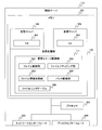
- FIG. 1 is a block diagram showing an embodiment of the present invention and showing an example of the configuration of a virtual machine system.
- the virtual computer system includes a plurality of physical servers (physical computers) 112 that execute a plurality of virtual servers (virtual computers) 109 on a virtualization mechanism (virtualization unit) 110, a plurality of physical servers 112, and a storage device 113.
- the management server 101 that is managed, the network 108 that connects the management server 101 and the plurality of physical servers 112, and the storage device 113 that is connected to the management server 101 and the physical servers 112 and stores information are mainly configured. .
- the virtualization mechanism 110 operating on the physical server 112 is configured with, for example, a hypervisor, a VMM (Virtual Machine Monitor), etc., and divides the computer resources of the physical server 112 and assigns them to the virtual server 109.
- the plurality of physical servers 112 have the same configuration, and each physical server 112 is identified by reference numerals # 1 to # 3.
- Each virtual server 109 has the same configuration and is identified by reference numerals # 1 to # 6.
- FIG. 1 shows a state in which virtual server # 1 and virtual server # 2 are executed on physical server # 1.
- the storage device 113 includes a plurality of disk devices (physical disks) 114 and 115, and virtual disks 120 and 125 are set in each disk device 114.
- the virtual disk 120 set in the disk device 114 stores a boot image of the virtual server 109.
- the boot image can include system files such as an OS, middleware, and applications executed on the virtual server 109. Note that at least one virtual disk 120 is allocated to one virtual server 109.
- the virtual disk 125 set in the disk device 115 stores a patch file (correction file) such as an OS executed by the virtual server 109, and functions as a patch disk.
- patch file correction file
- virtual disks # 6 and # 7 are patch disks.
- the virtual disk 125 is described as the patch disk 125.
- the patch disk 125 stores a common patch file such as an OS executed by each virtual server 109.
- each virtual server 109 operates with a patch file applied by reading a file from a patch disk instead of a boot image as needed under the control of the virtual image control unit 111 of the virtualization mechanism 110. To do.
- the patch file stored in the patch disk 125 functions as a common patch file because a plurality of virtual servers 109 read it.
- the patch file stores a correction file corresponding to the OS type, version or update level, and the use of the patch file is managed by the patch management unit 103 described later.
- the management server 101 manages the physical server 112, the virtual server 109, and the virtual disks 120 and 125. Therefore, the management server 101 includes a virtualization mechanism management unit 102 that manages the virtualization mechanism 110 of each physical server 112, a physical server management table 104 that manages resources and operating states of each physical server 112, The virtual server management table 15 for managing the resources allocated to the virtual server 109 and the operating state of each virtual server, the patch management unit 103 for applying a patch file to the virtual server 109, and the patch file stored in the patch disk 125 A patch management table 106 for managing the patch file, and a virtual disk management table 107 for managing the application state of the patch file for each virtual disk 120.
- FIG. 2 is a block diagram illustrating an example of the configuration of the management server 101 according to the embodiment of this invention.
- the management server 101 includes a processor 202 that performs arithmetic processing, a memory 201 that stores data and programs, a network interface 203 that accesses the network 108, and a disk interface 204 that accesses the storage device 113.
- the virtualization mechanism management unit 102 and the patch management unit 103 are loaded as programs and executed by the processor 202.
- the above-described tables 104 to 107 are stored by the virtualization mechanism management unit 102 and the patch management unit 103. Stored in the memory 201.
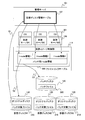
- FIG. 3 is a block diagram illustrating an example of the configuration of the physical server 112 according to the embodiment of this invention.
- the hardware configuration of the physical server 112 is the same as that of the management server 101, and includes a processor 202, a memory 201, a network interface 203, and a disk interface 204. Is different.
- the virtualization mechanism 110 that allocates the computer resources of the physical server 112 to the plurality of virtual servers 109 is loaded into the memory 201 of the physical server 112 and executed by the processor 202.
- a plurality of virtual servers 109 are executed on the virtualization mechanism 110, and an OS 301 and an application (not shown) are executed on each virtual server 109.
- the virtualization mechanism 110 divides the computer resources of the physical server 112 and assigns them to a plurality of virtual servers 109 in accordance with instructions from the management server 101.
- the virtualization mechanism 110 allocates a virtual disk 120 in the storage apparatus 113 connected to the virtual server 109 according to a command from the management server 101, and the virtual server 109 reads a boot image including the OS 301 from the allocated virtual disk 120. Start with.
- the virtualization mechanism 110 includes a virtual image control unit 111 that determines whether or not to apply the patch file of the patch disk 125 to the virtual server 109 and causes the virtual server 109 to read the patch file as necessary.
- the virtual image control unit 111 is a file in which a storage location (location) of a patch file to be applied to each virtual server 109 on the physical server 112 and a boot image file (system file) to which the patch file is applied are set in advance.
- the file link table 306 is referred to determine whether or not a patch file needs to be applied.
- a file control unit 302 that controls the server 109 to read a patch file on the patch disk 125, a file information collection unit 303 that acquires a virtual disk to which the patch file is applied for each virtual server 109, and a file location;
- the patch file to the virtual disk Includes a patch distribution unit 305 to write the 20, the file remapping unit 304 to write the relationship between files and the patch file patch file is applied to a file link table 306, a.
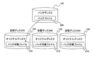
- FIG. 4 is a conceptual diagram showing processing for providing the virtual server with a patch file performed by the virtual image control unit 111.
- FIG. 5 is a conceptual diagram showing patch file distribution processing performed by the virtual image control unit 111.
- a patch file 200 that the management server 101 shares in advance with a plurality of virtual servers 109 is stored in a virtual disk 125 in the storage apparatus 113, and a predetermined number of virtual disks 120 allocated to each virtual server 109 The boot image is stored.
- the virtualization mechanism 110 of the physical server # 1 shown in FIG. 1 allocates virtual servers # 1 and # 2 according to a command from the virtualization mechanism management unit 102 of the management server 101.
- An example in which virtual disk # 1 is assigned to virtual server # 1 is shown.
- a technique in which the virtualization mechanism 110 allocates computer resources to the physical server # 1 may be a known or well-known technique and will not be described in detail here.
- the virtualization mechanism management unit 102 also stores information on the virtual disk 120 to which the patch file 200 is to be applied in the virtual disk management table 107, and the virtual disk # assigned to the virtual server # 1 in the virtual disk management table 107. The application status of one patch file 200 is stored.
- the file information collection unit 303 of the virtual image control unit 111 on the physical server # 1 stores the storage location (file path, virtual disk identifier) of the patch target file 210 to which the patch file 200 is applied from the management server 101, as will be described later.
- a file to which the patch file 200 needs to be applied in the virtual disk # 1 is referred to as a patch target file 210.
- the virtual disk 120 storing the boot image of the virtual server # 1 and the patch target file 210 is referred to as an original disk
- the virtual disk 125 storing the patch file 200 is referred to as a patch disk.
- the management server 101 assigns the virtual server # 1 to the virtualization mechanism 110 of the physical server # 1 and assigns the virtual disk # 1 to the virtual server # 1, the virtual server # 1 starts the virtual server # 1 before the virtual server # 1 starts.
- the disk management table 107 and the file link table 306 of the virtualization mechanism 110 of the physical server # 1 are updated.
- the file control unit 302 of the virtual image control unit 111 functions.
- the file control unit 302 refers to the file link table 306 and determines whether the access request of the virtual server # 1 is the patch target file 210 of the original disk. Determine whether.
- the file control unit 302 permits access to the requested file on the virtual disk # 1 as in the normal processing of the virtualization mechanism 110 (S2).
- the file control unit 306 stores the request to the virtual disk # 1 instead of the requested access to the virtual disk # 1 as the processing of the virtualization mechanism 110 of the present invention. Access to the file is permitted (S3).
- S3 Access to the file is permitted
- the file control unit 306 executes an access request to the virtual disk # 1 and responds to the virtual server # 1.
- the file control unit 306 may switch the path of the virtual disk accessed by the virtual server # 1.
- the file control unit 306 permits access to the requested file on the virtual disk # 1 in the same way as the normal virtualization mechanism 110 processing, and the virtual server # 1 is made to access the file on virtual disk # 1.
- the file control unit 306 switches the requested access path to the virtual disk # 1 to the patch disk and causes the virtual server # 1 to access the patch file 200. May be.
- the virtual server # 1 accesses the patch file 200 of the patch disk.
- the virtual image control unit 111 hides the patch target file 210 of the original disk and provides the patch file 200 with respect to the access to the patch target file 210 of the virtual server # 1.
- the virtual image control unit 111 can operate the virtual server # 1 in the same environment as after applying the patch file 200 without writing the patch file 200 on the original disk by the above processing.
- the administrator or the like when an urgent correction to a security hole is provided as the patch file 200, the administrator or the like first stores the patch file 200 from the management server 101 to the patch disk.
- a virtual server to which the patch file 200 is applied is determined from the patch file application state in the virtual server management table 105, and an original disk storing the patch target file 210 to which the patch file 200 is to be applied is described later.
- a virtual disk 120 (to which the patch file 200 is applied) is inquired from the file information collection unit 303 of the virtual image control unit 111 and the patch file 200 information of the patch disk and the original disk information acquired by the file information collection unit 303.
- the original disc) and the patch target file 210 are specified.
- the virtualization mechanism management unit 102 instructs the file remapping unit 304 of the virtual image control unit 111 to update the file link table 306.
- the file remapping unit 304 of the virtual image control unit 111 updates the file link table 306, and the relationship of the patch target file 210 to which the patch file 200 is applied is defined in the virtualization mechanism 110 of each physical server 112. .
- the virtual server accesses the patch target file 210 of the original disk for which the application of the patch file 200 is set in the virtual disk management table 107
- the virtual image control unit 111 is modified in place of the patch target file 210.
- a patch file 200 is provided.
- the virtual server can be operated in a state after providing the patch file 200 only by storing the patch file 200 in the patch disk and then the virtual image control unit 111 only updating the file link table 306. Become.
- the patch file 200 can be immediately provided to the OS 301 or application on the virtual server without performing distribution processing for replacing the patch target file 210 with the patch file 200 on the original disk.
- FIG. 4 shows an example in which the patch file 200 is provided to one virtual server # 1, but one patch file 200 is a plurality of virtual servers on a plurality of virtualization mechanisms 110 managed by the management server 101. 109 can be shared. Therefore, the patch file 200 of the patch disk can be handled as a common patch file between the virtual servers 109.
- the patch target file 210 to which the patch file 200 is to be applied is simply defined in the file link table 306, and the virtual servers # 1 to # 3 are patched to the original disk.
- the virtual image control unit 111 responds with the patch file 200 of the patch disk 125 instead of the patch target file 210 of each original disk.
- the patch file 200 can be collectively applied to a plurality of virtual servers.
- the patch file 200 can be executed by the virtual server 109 before the patch target file 210 of the original disk is updated with the patch file 200. Therefore, the patch file 200 is also applied to the stopped virtual server. Can be used. That is, if the location information (i-node information) of the patch file 200 that replaces the patch target file 210 is registered in the virtual disk management table 107 and the file link table 306, the virtual image control unit 111 activates the virtual server. Since the patch file 200 can be provided while hiding the patch target file 210 from time, it is possible to ensure security against the OS 301 and zero-day attack of the application, as compared with the conventional example.
- the virtual image control unit 111 conceals the patch target file 210 of the original disk and represents the provision of the patch file 200, the patch file 200 for one OS or application is accumulated and file control is performed. The processing of the unit 302 increases. Therefore, when a predetermined condition is satisfied, the virtual image control unit 111 executes a patch distribution process for replacing the patch target file 210 of the original disk with the patch file 200 of the patch disk as shown in FIG. .
- FIG. 5 shows an outline of patch distribution processing performed by the patch distribution unit 305 of the virtual image control unit 111.
- the patch distribution unit 305 monitors the resource load of the physical server # 1, and when the load of the physical server # 1 becomes less than the threshold value.
- the patch target file 210 of the original disk is updated with the patch file 200, and the patch is applied. Note that the usage rate of the processor 202 (physical processor) and the usage rate of the storage device 113 and the network 120 can be used as the resource load of the physical server # 1.
- This processing is provided by a plurality of virtual servers by distributing the patch target file 210 to the original disk when the load on the physical server # 1 is low when a plurality of virtual servers are operating on one physical server # 1. Multiple services can be prevented from being delayed.
- the patch distribution unit 305 starts distributing and applying the patch file 200 when the load on the resources of the physical server # 1 is less than a predetermined threshold when the patch file 200 is written to the plurality of virtual servers 109. To do. That is, the patch file 200 is distributed by background processing. Further, access to the patch target file is invalidated until the application of the patch file 200 is completed.
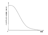
- the load on the patch disk when patch distribution is performed in parallel when a large number of virtual servers 109 are operating on the physical server # 1 is as shown in FIG.
- FIG. 6 is a graph showing the relationship between the passage of time from the start of the patch distribution process and the load on the patch disk.
- the load on the patch disk can be represented by, for example, a data transfer amount (MB / S) per unit time.
- MB / S data transfer amount
- FIG. 7 shows a physical server management table 104 managed by the virtualization mechanism management unit 102.
- the physical server management table 104 includes a physical server identifier 701 that stores the identifier of the physical server 112, a CPU 702 that stores information related to the performance of the processor 202, a memory 703 that stores the capacity of the memory 201, and an I included in the physical server 112.
- One record is configured from the device 704 that stores the identifier assigned to the / O device and the connection disk 705 that stores the identifier and capacity of the disk device 114 of the storage device 113 assigned to the physical server 112.
- an identifier (for example, # 1 to # 3) assigned by the virtualization mechanism management unit 102 is stored.
- the CPU 702 stores the operating frequency and the number of cores of the processor 202, and the memory 703 stores the capacity of the memory 201.
- the device 704 stores identifiers of all I / O devices included in the physical server 112 (or connected to the physical server 112), and stores MAC addresses when the type of the I / O device is a network interface. In the case of HBA (Host Bus Adaptor), WWN is stored.
- the connection disk 705 stores the identifier and capacity of the disk device 114 that can be accessed by the physical server 112 among the disk devices 114 of the storage device 113.
- FIG. 8 shows a virtual server management table 105 managed by the virtualization mechanism management unit 102.
- the virtual server management table 105 includes a virtualization mechanism identifier 801 that stores an identifier of the virtualization mechanism 110 operating on the physical server 112 and a physical server identifier 802 that stores an identifier of the physical server 112 on which the virtualization mechanism 110 is executed.
- a virtual server identifier 803 that stores the identifier of the virtual server 109 provided by the virtualization mechanism 110, an allocation resource 804 that stores resources of the physical server 112 and the storage device 113 allocated to the virtual server 109, and a virtual server 109
- an identifier for example, # 1 to # 3 of the virtualization mechanism 110 assigned by the virtualization mechanism management unit 102 is stored.
- the virtual server identifier 803 stores the identifier (for example, # 1 to # 6) of the virtual server 109 assigned by the virtualization mechanism management unit 102.
- FIG. 8 shows an example of a state where the virtual server # 4 of the physical server # 2 shown in FIG. 1 is not assigned.
- the allocated resource 804 stores processor performance information (for example, operating frequency ⁇ number of cores) allocated to the virtual server 109, memory capacity, I / O device identifier, and virtual disk identifier.
- FIG. 8 shows an example in which, in the physical server # 1, virtual disk # 1 is assigned to virtual server # 1, and virtual disk # 2 is assigned to virtual server # 2.
- FIG. 8 shows an example in which virtual servers # 1, # 2, and # 5 execute OS_A, and virtual servers # 3 and # 6 execute OS_B.
- the applied patch 806 stores an identifier of a patch that has been applied to the OS 301 executed by the virtual server 109.
- OS_A includes patches 1 and 3
- OS_B includes patch 2
- only patch 1 is applied to OS_A of virtual server # 1
- patch 3 is not applied.
- OS_B of server # 6 shows an example in which no patch is applied.
- at least one patch file 200 is associated with the identifiers of the patches 1 to 3.
- the status 807 stores information on whether or not the virtual server 109 is in operation, and FIG. 8 shows an example in which the virtual servers # 1, # 2, # 3, and # 6 are in operation.
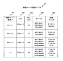
- FIG. 9 shows an example of the patch management table 106 managed by the patch management unit 103.
- the patch management table 106 includes a patch identifier 901 of the applied patch 806 of the virtual server management table 105 in FIG. 8, a target OS 902 that stores the type of OS targeted by the patch identifier, and a file to which the patch file 200 is applied.
- a record is composed of
- patch 3 is a patch file group targeted for OS_A and stored in virtual disk # 6, and patch target files 210 to which patch file 200 is applied are “3_file_00” to “3_file_06”.
- the location of the patch file is indicated by “13_fileinfo_00” to “13_fileinfo_06”.
- the patch management table 106 can be created in advance by the administrator of the management server 101 or the like via the patch management unit 103.
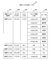
- FIG. 10 shows an example of the virtual disk management table 107 managed by the patch management unit 103.
- the virtual disk management table 107 includes a virtual disk identifier 1001 that stores an identifier (for example, # 1 to # 5) of the virtual disk 120 that stores the boot image of the virtual server 109, and an identifier of the disk device 114 that stores the virtual disk.
- a patch patch 1003 that stores a patch identifier to be applied to the virtual disk, and a file that stores patch file information (corresponding to 905 in FIG. 9) of the patch file corresponding to the patch identifier
- One record is constituted by the information 1004 and the status 1005 indicating whether or not the patch file indicated by the file information has been applied to the virtual disk.
- “NULL” indicating that there is no patch to be applied is stored in the virtual disks # 2 to # 4, and the fact that the patch 3 is applied is stored in the virtual disk # 1.
- Disc # 5 stores that patch 2 is applied.
- “13_fileinfo_00” and “13_fileinfo_01” of the patch 3 indicate that the application to the virtual disk # 1 is completed, “13_fileinfo_02” is being applied to the virtual disk # 1, and “13_fileinfo_03”.
- “13_fileinfo — 06” indicates that application to the virtual disk # 1 has not been completed.
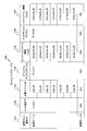
- FIG. 11 shows an example of the file link table 306 managed by the virtual image control unit 111 of each virtualization mechanism 110.
- the file link table 306 is a table for managing the relationship between the virtual server 109 using the virtual disk 120 storing the boot image, the file to which the patch is applied in the virtual disk 120, and the patch file.
- the file link table 306 includes a virtual machine identifier 1101 that stores the identifier of the virtual server 109 to which the patch file is applied, a patch identifier 1102 that stores an identifier of the patch to be applied, and a virtual disk 120 to which the patch file is applied.
- a patch disk volume 1106 that stores the identifier of the virtual disk 125 that stores the patch file to be applied, and patch file information 1107 that stores the location of the patch file. It is made.
- FIG. 11 shows an example in which seven patch files of patch 3 are applied to the virtual disk # 1 assigned to the virtual server # 1, and the applied patch files are stored in the virtual disk # 6. Note that “NULL” is stored in each item of the virtual server # 2, indicating that there is no patch file to be applied.
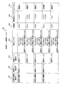
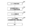
- FIG. 12 is a flowchart illustrating an example of patch file registration processing performed by the patch management unit 103 of the management server 101. This process is a process executed in response to a command from the administrator of the management server 101 and is activated when the administrator or the like registers the patch file 200 in the patch disk (virtual disk 125).
- step 1401 the patch management unit 103 of the management server 101 receives the location, patch disk (virtual disk 125) and storage location (patch file information 905) of the patch file 200 included in the administrator's command,
- the specified patch file is written to the storage location of the specified virtual disk 125.
- the administrator includes the target OS 902 of the patch file 200, the patch identifier 901, the patch target file name 903, the virtual disk 125 (disk volume 904) that stores the patch file, and the virtual disk 125 of the patch file.
- the management server 101 includes the target OS 902 of the patch file 200, the patch identifier 901, the patch target file name 903, the virtual disk 125 (disk volume 904) that stores the patch file, and the virtual disk 125 of the patch file.
- step 1402 the patch management unit 103 registers the information of the patch file 200 written in the storage location of the virtual disk 125 in the patch management table 106. By this process, a new record is generated in the patch management table 106, and the patch file 200 is registered.
- step 1403 the patch management unit 103 notifies the virtualization mechanism management unit 102 of the new patch identifier 901 added to the patch management table 106.
- a new patch file 200 is stored in the virtual disk 125, and a new record is added to the patch management table 106.
- the notification processing in step 1403 may notify the new patch identifier and patch file 200 when there is an inquiry from the virtualization mechanism management unit 102 in step 1301 in FIG. .
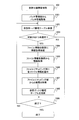
- FIG. 13 is a flowchart illustrating an example of patch file registration processing performed by the virtualization mechanism management unit 102. This process is started by a command from an administrator or the like when registering the patch file. Alternatively, the process of FIG. 13 may be executed after the process of FIG.
- the virtualization mechanism management unit 102 acquires information on the patch file 200 (patch identifier 901, target OS 902, target file name 903, etc.) from the patch management unit 103.
- the patch management unit 103 notifies the information from the patch file 200 registered in the patch management table 106 in response to the inquiry from the virtualization mechanism management unit 102.
- the patch management unit 103 may notify only the newly added patch file 200 to the patch management table 106 or may notify all the patch management tables 106 of the patch management table 106.
- the patch management table 106 is provided with a flag (not shown) indicating whether or not the newly registered patch file 200 has been notified to the virtualization mechanism management unit 102, and identifies the patch file 200 to be notified. Can do.
- step 1302 and subsequent steps the processing in steps 1302 to 1309 is repeated according to the number of patch files 200 acquired in step 1301 and the number of virtual servers in the virtual server management table 105.
- the virtualization mechanism management unit 102 selects one patch file 200 as the focused patch file 200, and repeats the subsequent processing for each patch file 200.
- the virtualization mechanism management unit 102 sequentially refers to the virtual server management table 104 in FIG. 8 from the first record.
- the OS type 805 executed on the virtual server is changed to the above step 1301. It is determined whether the patch identifier 901 of the patch file 200 that matches the target OS 902 of the acquired patch file 200 and is currently focused is not applied.
- the virtualization mechanism management unit 102 refers to the virtual server management table 105 and determines that the virtual server 109 has not been applied if the patch identifier 901 of the acquired patch file 200 is not included in the applied patch 806.
- the identifier of the virtual server 109 (virtual server identifier 803) is set as the target.
- the process proceeds to step 1304 as the virtual server identifier.
- the process proceeds to step 1309.
- step 1304 the virtualization mechanism management unit 102 sends the patch file 200 with the target virtual server identifier to the file information collection unit 303 of the virtualization mechanism 110 that provides the virtual server 109 that executes the OS 301 that matches the target OS 902. Is requested to acquire the location of the patch target file 210 (target file name 903) to which is applied.
- the file information collection unit 303 stores the location of the patch target file corresponding to the target file name 903 and the patch target file among the files stored in the virtual disk 120 allocated to the virtual server 109. The identifier of the virtual disk 120 obtained is acquired.
- step 1305 the virtualization mechanism management unit 102 stores the location of the patch target file corresponding to the patch target file name 903 in the virtual disk 120 collected by the file information collection unit 303 from the virtualization mechanism 110 and the patch target file.
- the identifier of the designated virtual disk 120 is acquired.
- the virtualization mechanism management unit 102 determines the target virtual server identifier, the patch identifier 901 of the patch file 200 currently focused on, the identifier of the virtual disk 125 (disk volume 904), and the location of the patch file 200 (patch file). Information 905), the target file name 903, the location of the patch target file name 903 acquired in step 1305, and the identifier of the virtual disk 120 in which the patch target file corresponding to the patch target file name 903 is stored
- the file remapping unit 304 is notified, and an update of the file link table 306 is requested.
- step 1307 the virtualization mechanism management unit 102 receives from the file remapping unit 304 that the update of the contents of the file link table 306 has been completed.
- the virtualization mechanism management unit 102 adds information on the patch file 200 currently focused on to the virtual disk management table 107. That is, the virtualization mechanism management unit 102 stores the identifier of the virtual disk 120 to which the currently focused patch file 200 is applied in the virtual disk identifier 1001 of the virtual disk management table 107, and the virtual file to which the patch file 200 is applied.
- the identifier of the disk 120 is stored in the disk volume 1002
- the patch identifier of the patch file 200 is stored in the link patch 1003
- the location of the patch file 200 (patch file information 905) is added to the file information 1004, and “unapplied” in the status 1005 "Is set.
- step 1309 the virtualization mechanism management unit 102 determines whether or not the above processing has been completed for all the virtual servers 109 and all the patch files 200 acquired in step 1301. If all the virtual servers 109 and all the patch files 200 are not completed, the above processing is repeated for the next patch file 200 or the next virtual server 109. On the other hand, if the above processing is completed for all the virtual servers 109 and all the patch files 200, the processing of this flowchart ends.
- FIG. 14 is a flowchart showing an example of processing performed by the file information collection unit 303 of the virtualization mechanism 110 performed in steps 1304 and 1305.
- step 1501 the file information collection unit 303 receives the name (target file name 903) of the patch target file 210 to which the patch file 200 is applied from the virtualization mechanism management unit 102, and the target virtual server identifier.
- step 1502 the file information collection unit 303 searches the virtual disk 120 (original disk) assigned to the virtual server identifier to be patched for a file name that matches the target file name 903, and matches the file. Is the location of the patch target file 210, and the identifier of the virtual disk 120 storing the patch target file 210 is specified.
- step 1503 the file information collection unit 303 notifies the virtualization mechanism management unit 102 of the location of the patch target file 210 specified in step 1502 and the identifier of the virtual disk 120 (original disk), and ends the process.
- FIG. 15 is a flowchart showing an example of processing performed by the file remapping unit 304 of the virtual image control unit 111 performed in steps 1306 and 1307.
- the file remapping unit 304 receives the target virtual server identifier from the virtualization mechanism management unit 102, the patch identifier 901 of the patch file 200, the identifier (disk volume 904) of the virtual disk 125 (patch disk), and the patch.
- the location of the file 200 (patch file information 905), the target file name 903, the location of the patch target file 210 acquired in step 1305, and the identifier of the virtual disk 120 in which the patch target file is stored are received.
- the file remapping unit 304 stores the target virtual server identifier in the virtual machine identifier 1101, the patch identifier 901 of the patch file 200 as the patch identifier 1102, the target file name 903 as the target file name 1103, and the virtual file identifier 1103.
- the identifier of the disk 120 is in the original disk volume 1104, the location of the patch target file 210 is in the original file information 1105, the identifier of the virtual disk 125 (patch disk) (disk volume 904) is in the patch disk volume 1106, and the location of the patch file 200 is (Patch file information 905) is stored in the patch file information 1107, and the file link table 306 is updated.
- the patch target file 210 and the patch file 200 that are not applied to the virtual server 109 are registered in the file link table 306.
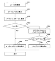
- FIG. 16 is a flowchart showing an example of processing performed by the file control unit 302 of the virtual image control unit 111 shown in FIG. This process is executed when a file is accessed from the OS 301 or an application running on the virtual server 109.
- step 1201 the file control unit 302 accepts a file access request from the OS 301 or application of the virtual server 109.
- step 1202 the file control unit 302 acquires the file name of the accepted file and refers to the file link table 306.
- step 1203 if the acquired file name exists in the target file name 1103 of the file link table 306, the file control unit 302 determines that the access is to the patch target file 210 in which the patch file exists, and step 1204. If not, go to Step 1206.
- step 1204 the time stamp of the file (patch target file 210) of the original file information 1105 of the file link table 306 and the time stamp (file of the patch file information 1107 (patch file 200)). Compare update time).
- step 1205 if the result of the comparison shows that the original file information 1105 file is newer than the patch file information 1107 file, the process advances to step 1206, and the patch file information 1107 file is newer than the original file information 1105 file. If YES, go to step 1207.
- Step 1206 reads the requested file from the virtual disk 120 that is the original disk when the original file information 1105 file is newer than the patch file information 1107 file or when the patch file 200 does not exist, and the virtual server Responds to 109 OS 301.
- step 1207 when the patch file 200 of the patch file information 1107 is newer than the patch target file 210 of the original file information 1105, the requested patch file 200 is read from the virtual disk 125 which is a patch disk, and the virtual server 109 Responds to the OS 301.
- the patch file 200 is newer than the patch target file 210 of the original disk by the above processing, the patch file 200 is read from the patch disk instead of the original disk and responds to the OS 301 to thereby respond to the patch target file 210 of the original disk.
- the OS 301 or the application can be operated in a state equivalent to that after the patch file 200 is applied without applying the patch file 200 to the server, and security vulnerabilities and bugs can be quickly suppressed.
- step 1201 when the file access request is writing, the processing may be terminated by writing the requested file.
- FIG. 17 is a flowchart illustrating an example of patch distribution processing performed by the patch distribution unit 305 of the virtual image control unit 111. This process can be executed by the virtualization mechanism 110 in the background.
- the patch distribution unit 305 monitors the resource load of the physical server 112.
- the usage rate of the processor 202 physical processor
- the usage rate of the storage device 113 or the network 108 can be used as described above. Further, the usage rate of the processor 202 may monitor the usage rate of the virtual processor provided by the virtualization mechanism 110.
- the virtual server 109 to which the patch file 200 is applied is determined under a predetermined condition when the monitored load is less than a preset threshold value.
- a predetermined condition for example, a plurality of virtual servers 109 provided by the virtualization mechanism 110 are selected within a preset number of parallel processes. For example, when the number of parallel processes is 2, the virtual servers 109 are processed two by two. Then, the patch file 200 and the patch target file 210 are selected for each virtual server 109 with reference to the file link table 306.
- step 1703 the patch distribution unit 305 notifies the virtualization mechanism management unit 102 of the virtual server 109 and the patch file 200 determined in step 1702.
- the virtualization mechanism management unit 102 updates the status 1005 of the virtual disk management table 107 during application of the virtual server 109 and the patch file 200 to which the patch received from the patch distribution unit 305 is applied (1801, 1802).
- step 1704 the patch distribution unit 305 reads the patch file 200 from the patch disk, updates the patch target file 210 of the virtual disk 120 assigned to the virtual server 109 to which the patch is applied, and applies the patch. .
- step 1705 the patch distribution unit 305 updates the patch target file 210 with the patch file 200, and notifies the virtualization mechanism management unit 102 that the patch application has been completed.
- the virtualization mechanism management unit 102 updates the status 1005 of the virtual disk management table 107 to “applied” for the virtual server 109 and the patch file 200 based on the patch completion notification received from the patch distribution unit 305 (1804). Further, the virtualization mechanism management unit 102, when all the patch files 200 corresponding to the patch identifiers stored in the link patch 1003 of the virtual disk management table 107 have been applied, the virtual server to which the virtual disk identifier 1001 is assigned. 109 is searched from the allocation resource 804 of the virtual server management table 105 and a patch identifier is added to the applied patch 806.
- the virtualization mechanism management unit 102 applies the virtual disk identifier 1001 to which the patch file 200 is applied.
- the link patch 1003, file information 1004, and status 1005 corresponding to are updated to NULL.
- the record corresponding to the virtual disk identifier 1001 to which the patch file 200 is applied may be deleted.
- step 1706 the patch distribution unit 305 deletes and updates the record of the file link table 306 for which the patch application has been completed. Thereby, the file control unit 302 accesses the original disk when accessing the file to which the patch is applied, and can suppress an increase in processing load.
- step 1707 the patch distribution unit 305 determines whether or not the application of all target patch files 200 has been completed for the currently selected virtual server 109. If not, the process returns to step 1702 to apply the patch to the next patch file 200 or the remaining virtual server 109.
- the patch distribution unit 305 updates the patch target file 210 with the patch file 200, and the record of the file link table 306 is deleted. Also, the virtualization mechanism management unit 102 updates the applied patch 806 of the virtual server management table 105, and the virtual disk management table 107 updates the record of the link patch 1003 to which the patch file 200 has been applied to NULL (or Deleted) and discarded.
- the patch management table 106 can be managed manually by an administrator of the management server 101 or the like.
- the example in which the patch distribution unit 305 detects the load on the physical server 112 and automatically applies the patch is shown.
- the monitoring of the load in step 1701 is omitted, and the management server
- the processing from step 1702 onward may be performed by a command from the administrator 101. That is, the patch distribution unit 305 may perform the processing from step 1702 onward when a predetermined condition is satisfied when the load on the physical server 112 becomes less than the threshold or when an instruction from an administrator or the like is accepted.
- the virtual server 109 to which the patch file 200 is applied may be determined by selecting a plurality of virtual servers 109 one by one and applying each patch file 200.
- the file control unit 302 reads the file and responds to the virtual server 109. However, the file control unit 302 switches between the access path of the original disk and the access path of the patch disk to change the virtual path.
- the server 109 may be configured to allow either one of the accesses.
- each virtual machine reads a common correction file (patch file) from the second storage unit according to the file link information, and enters the state in which the correction file is applied, and the virtual machine accesses the virtual machine.
- the correction file can be applied to a plurality of virtual machines in a lump.
- the modification file can be used by the virtual machine and the modification file can be applied to the virtual machine.
- the present invention can be applied particularly to a virtual machine system including a plurality of physical servers each including a virtualization mechanism and a management server that manages each virtualization mechanism.
Abstract
Disclosed is a virtual computer system comprising a virtualization unit, files for activating virtual computers, and a storage device for storing correction files to be applied to the first-mentioned files; wherein the virtualization unit comprises file link information in which correspondence relationships between the first-mentioned files and the correction files have been set, and a file control unit, for controlling access to the files from the virtual computers, receives access to the first-mentioned file from a virtual computer and refers to the file link information, whereupon if a correction file to be applied to the first-mentioned file does not exist, the first-mentioned file to which the access was requested is provided to the virtual computer, and if a correction file to be applied to the file to which the access was requested does exist, the correction file is provided to the virtual computer.
Description
本発明は、複数のOSを稼動させる仮想計算機システムにおいて、各OS等の保守を行う技術に関する。
The present invention relates to a technique for maintaining each OS in a virtual machine system that operates a plurality of OSs.
近年、半導体製造技術の向上により、1つのプロセッサに複数のプロセッサコアを搭載するマルチコア技術が開発され、プロセッサの処理性能が向上している。プロセッサの処理性能向上に伴い、1つの計算機上に複数の仮想的な計算機を稼動させる仮想計算機技術を採用することによって、処理能力が向上したプロセッサを効率的に利用することが可能になった。
In recent years, due to improvements in semiconductor manufacturing technology, multi-core technology in which a plurality of processor cores are mounted on one processor has been developed, and the processing performance of the processor has been improved. With the improvement of processor processing performance, it has become possible to efficiently use processors with improved processing capabilities by employing virtual computer technology that operates a plurality of virtual computers on one computer.
仮想化技術では、計算機上に仮想化ソフトウェア、いわゆる、仮想マシンモニタ(VMM:Virtual Machine Monitor)やハイパーバイザを動作させ、仮想化ソフトウェア上に仮想計算機を生成する。個々の仮想計算機上では、それぞれ独立したOSをゲストOSとして動作させることができる。
In the virtualization technology, virtualization software, so-called virtual machine monitor (VMM: Virtual Machine Monitor) or hypervisor is operated on a computer to generate a virtual machine on the virtualization software. An independent OS can be operated as a guest OS on each virtual machine.
ゲストとなるOSでは、セキュリティホールやバグなどを解消するための修正ファイル(または修正プログラムあるいはパッチファイル)が頻繁に配布されている。多数の計算機を運用するデータセンタなどでは、複数種のOSに加えて、各種類毎のバージョン(例えば、2000、2003、2008等)を稼動させている場合が多く、また、各バージョン内でも複数のアップデートの種類(例えば、SP1、SP2やカーネル2.6.1.4や2.6.1.6等)が複数存在し、管理者はOSの種類、バージョン、アップデートの種類毎に各OSの修正ファイルを管理し、各ゲストOSに適用することが要求される。上記修正ファイルの管理と適用は、計算機の数が多くなるにつれて、管理者などの労力が過大になる。
In the guest OS, correction files (or correction programs or patch files) for resolving security holes and bugs are frequently distributed. In a data center that operates a large number of computers, in addition to a plurality of types of OS, a version for each type (for example, 2000, 2003, 2008, etc.) is often operated, and a plurality of versions are also included in each version. There are a plurality of update types (for example, SP1, SP2, kernel 2.6.1.4, 2.6.1.6, etc.), and the administrator sets each OS type, version, and update type for each OS. It is required to manage the modified file and apply it to each guest OS. As for the management and application of the correction file, as the number of computers increases, the labor of an administrator or the like becomes excessive.
このため、上記修正ファイルを各計算機へ自動的に適用する技術として、特許文献1、2に開示された技術が知られている。特許文献1に開示された技術では、クラスタを構成する計算機のうちパッチファイルを適用する計算機をクラスタから切り離し、切り離した後にパッチファイルを適用する。パッチファイルの適用は、各計算機に配備したエージェント等が行う。また、特許文献2に開示された技術では、複数の装置に対して並列してアップデートファイルを配信してアップデートファイルを各装置で適用する。
For this reason, the techniques disclosed in Patent Documents 1 and 2 are known as techniques for automatically applying the modified file to each computer. In the technique disclosed in Patent Document 1, a computer to which a patch file is applied is separated from the cluster among computers constituting the cluster, and the patch file is applied after the separation. The patch file is applied by an agent or the like deployed on each computer. In the technique disclosed in Patent Document 2, an update file is distributed in parallel to a plurality of devices, and the update file is applied to each device.
近年、セキュリティ対策が重要度を増す中、修正ファイルの配布及び適用は、上記従来例のように、管理計算機が修正ファイルを対象の計算機に配布し、各計算機で修正ファイルが適用する手法が一般的である。
In recent years, as security measures have become more important, the distribution and application of correction files is generally performed by the management computer distributing the correction file to the target computer and applying the correction file to each computer, as in the previous example. Is.
修正ファイルを適用する際には、計算機の再起動が必要となる場合があり、多数の計算機を運用するデータセンタなどでは、各計算機が提供するサービスを停止させずに修正ファイルを適用する計画を設定しなければならず、ゼロデイアタックのような緊急度の高いセキュリティパッチなどの修正ファイルを至急適用する必要がある場合でも、一括して修正ファイルを適用することができない、という問題があった。
When applying a correction file, it may be necessary to restart the computer. In data centers that operate a large number of computers, there is a plan to apply the correction file without stopping the services provided by each computer. Even if it is necessary to apply a correction file such as a security patch with a high degree of urgency such as zero-day attack, it is not possible to apply the correction file all at once.
すなわち、一括して複数の計算機に修正ファイルを適用した場合、各計算機では修正ファイルを適用するプログラムを実行するために処理負荷が高くなり計算機のリソースが不足して修正ファイルの適用完了まで時間がかかる可能性がある。このため、計算機が提供するサービスの処理が遅延する恐れがあった。仮想計算機を利用する場合では、複数の仮想計算機に一括して修正ファイルを適用するプログラムを実行させると、物理計算機の負荷が過大になる可能性がある、という問題があった。
In other words, when a correction file is applied to multiple computers at once, the processing load increases on each computer to execute the program that applies the correction file, and there is a shortage of computer resources. There is such a possibility. For this reason, there is a possibility that the processing of the service provided by the computer is delayed. In the case of using a virtual machine, there is a problem that if a program for applying a correction file is executed in a batch on a plurality of virtual machines, the load on the physical machine may become excessive.
また、上記従来技術では、修正ファイルを適用する際に計算機を起動させておく必要があり、コールドスタンバイなどで停止している計算機には修正ファイルを適用することができない。このため、計算機を起動したときにゼロデイアタック等の脆弱性を有した状態で稼動せざるを得ない、という問題もあった。
Also, in the above prior art, it is necessary to start the computer when applying the correction file, and the correction file cannot be applied to a computer that is stopped by cold standby or the like. For this reason, there was also a problem that when the computer was started, it had to be operated in a state having a vulnerability such as zero day attack.
そこで、本発明は上記問題点に鑑みてなされたもので、複数の計算機に修正ファイルを一括して適用することを目的とする。さらに、仮想計算機を用いた環境において、仮想計算機の起動する際に、修正ファイルを利用可能とすることを目的とする。
Therefore, the present invention has been made in view of the above problems, and an object thereof is to apply correction files to a plurality of computers at once. It is another object of the present invention to make it possible to use a correction file when starting a virtual machine in an environment using the virtual machine.
本明細書において開示される発明の代表的な一例を示せば以下の通りである。すなわち、プロセッサとメモリとを備えた物理計算機と、前記物理計算機のリソースを分割して仮想計算機を提供する仮想化部と、前記物理計算機からアクセス可能なストレージ装置と、を備えた仮想計算機システムであって、前記ストレージ装置は、前記仮想計算機を起動させる複数のファイルを格納した第1の記憶部と、前記ファイルに適用される修正ファイルを格納した第2の記憶部と、を含み、前記仮想化部は、前記第1の記憶部のファイルと、当該ファイルに適用される前記第2の記憶部の修正ファイルとの対応関係を含むファイルリンク情報と、前記仮想計算機から前記ストレージ装置の前記ファイルに対するアクセスを制御するファイル制御部と、を有し、前記ファイル制御部は、前記仮想計算機から前記第1の記憶部に格納されたファイルに対するアクセスを受け付けて、前記ファイルリンク情報を参照して当該ファイルに適用される修正ファイルの有無を判定し、前記ファイルに適用される修正ファイルが存在しない場合には、前記要求された前記第1の記憶部からファイルを前記仮想計算機に提供し、前記ファイルに適用される修正ファイルが存在する場合には、前記第2の記憶部の修正ファイルを前記要求されたファイルとして前記仮想計算機に提供する。
A typical example of the invention disclosed in this specification is as follows. That is, a virtual computer system including a physical computer including a processor and a memory, a virtualization unit that divides resources of the physical computer and provides a virtual computer, and a storage device that is accessible from the physical computer. The storage device includes a first storage unit that stores a plurality of files for starting the virtual computer, and a second storage unit that stores a correction file applied to the file, The file conversion unit includes file link information including a correspondence relationship between the file in the first storage unit and the modified file in the second storage unit applied to the file, and the file in the storage device from the virtual machine A file control unit that controls access to the file, and the file control unit is stored in the first storage unit from the virtual machine The access to the received file is received, the presence / absence of the correction file applied to the file is determined with reference to the file link information, and when the correction file applied to the file does not exist, the requested When the file from the first storage unit is provided to the virtual machine and there is a modified file to be applied to the file, the modified file in the second storage unit is set as the requested file to the virtual machine. To provide.
本発明の一実施の形態により、複数の仮想計算機に対して一括して修正ファイルを適用することが可能となる。
According to an embodiment of the present invention, it is possible to apply correction files to a plurality of virtual machines at once.
以下、本発明の一実施形態を添付図面に基づいて説明する。
Hereinafter, an embodiment of the present invention will be described with reference to the accompanying drawings.
図1は、本発明の実施形態を示し、仮想計算機システムの構成の一例を示すブロック図である。
FIG. 1 is a block diagram showing an embodiment of the present invention and showing an example of the configuration of a virtual machine system.
仮想計算機システムは、仮想化機構(仮想化部)110上で複数の仮想サーバ(仮想計算機)109を実行する複数の物理サーバ(物理計算機)112と、複数の物理サーバ112とストレージ装置113とを管理する管理サーバ101と、管理サーバ101と複数の物理サーバ112とを接続するネットワーク108と、管理サーバ101と物理サーバ112とに接続されて情報を格納するストレージ装置113を主体にして構成される。
The virtual computer system includes a plurality of physical servers (physical computers) 112 that execute a plurality of virtual servers (virtual computers) 109 on a virtualization mechanism (virtualization unit) 110, a plurality of physical servers 112, and a storage device 113. The management server 101 that is managed, the network 108 that connects the management server 101 and the plurality of physical servers 112, and the storage device 113 that is connected to the management server 101 and the physical servers 112 and stores information are mainly configured. .
物理サーバ112で稼動する仮想化機構110は、例えば、ハイパーバイザやVMM(Virtual Machine Monitor)などで構成されて物理サーバ112の計算機リソースを分割し、仮想サーバ109に割り当てる。複数の物理サーバ112は同一の構成であり、各物理サーバ112は、符号#1~#3で識別される。また、各仮想サーバ109も同様の構成であり符号#1~#6で識別される。図1は、物理サーバ#1で仮想サーバ#1と仮想サーバ#2が実行されている状態を示す。
The virtualization mechanism 110 operating on the physical server 112 is configured with, for example, a hypervisor, a VMM (Virtual Machine Monitor), etc., and divides the computer resources of the physical server 112 and assigns them to the virtual server 109. The plurality of physical servers 112 have the same configuration, and each physical server 112 is identified by reference numerals # 1 to # 3. Each virtual server 109 has the same configuration and is identified by reference numerals # 1 to # 6. FIG. 1 shows a state in which virtual server # 1 and virtual server # 2 are executed on physical server # 1.
ストレージ装置113は、複数のディスク装置(物理ディスク)114、115を備え、各ディスク装置114には仮想ディスク120、125が設定される。ディスク装置114に設定された仮想ディスク120には仮想サーバ109のブートイメージが格納される。ブートイメージは、仮想サーバ109で実行されるOSやミドルウェア及びアプリケーション等のシステムファイルを含むことができる。なお、ひとつの仮想サーバ109には少なくとも一つの仮想ディスク120が割り当てられる。
The storage device 113 includes a plurality of disk devices (physical disks) 114 and 115, and virtual disks 120 and 125 are set in each disk device 114. The virtual disk 120 set in the disk device 114 stores a boot image of the virtual server 109. The boot image can include system files such as an OS, middleware, and applications executed on the virtual server 109. Note that at least one virtual disk 120 is allocated to one virtual server 109.
また、ディスク装置115に設定された仮想ディスク125には、仮想サーバ109で実行されるOS等のパッチファイル(修正ファイル)が格納されて、パッチディスクとして機能する。図示の例では、仮想ディスク#6、#7がパッチディスクである。以下の説明では、仮想ディスク125をパッチディスク125として説明する。パッチディスク125には、各仮想サーバ109で実行されるOS等の共通のパッチファイルを格納する。後述するように、仮想化機構110の仮想イメージ制御部111の制御により、各仮想サーバ109が必要に応じてブートイメージに代わってパッチディスクからファイルを読み込むことによって、パッチファイルを適用した状態で稼動する。このため、パッチディスク125に格納されたパッチファイルは、複数の仮想サーバ109が読み込むため共通のパッチファイルとして機能する。なお、パッチファイルは、OSの種類やバージョンまたはアップデートのレベルなどに応じた修正ファイルが格納され、後述のパッチ管理部103によってパッチファイルの利用が管理される。
Also, the virtual disk 125 set in the disk device 115 stores a patch file (correction file) such as an OS executed by the virtual server 109, and functions as a patch disk. In the illustrated example, virtual disks # 6 and # 7 are patch disks. In the following description, the virtual disk 125 is described as the patch disk 125. The patch disk 125 stores a common patch file such as an OS executed by each virtual server 109. As will be described later, each virtual server 109 operates with a patch file applied by reading a file from a patch disk instead of a boot image as needed under the control of the virtual image control unit 111 of the virtualization mechanism 110. To do. Therefore, the patch file stored in the patch disk 125 functions as a common patch file because a plurality of virtual servers 109 read it. The patch file stores a correction file corresponding to the OS type, version or update level, and the use of the patch file is managed by the patch management unit 103 described later.
管理サーバ101は、物理サーバ112、仮想サーバ109及び仮想ディスク120、125を管理する。このため、管理サーバ101は、各物理サーバ112の仮想化機構110を管理する仮想化機構管理部102と、各物理サーバ112のリソースや稼動状態を管理するための物理サーバ管理テーブル104と、各仮想サーバ109に割り当てられるリソースと各仮想サーバの稼動状態を管理するための仮想サーバ管理テーブル15と、仮想サーバ109にパッチファイルを適用するパッチ管理部103と、パッチディスク125に格納されたパッチファイルを管理するためのパッチ管理テーブル106と、仮想ディスク120毎にパッチファイルの適用状態を管理するための仮想ディスク管理テーブル107を含む。
The management server 101 manages the physical server 112, the virtual server 109, and the virtual disks 120 and 125. Therefore, the management server 101 includes a virtualization mechanism management unit 102 that manages the virtualization mechanism 110 of each physical server 112, a physical server management table 104 that manages resources and operating states of each physical server 112, The virtual server management table 15 for managing the resources allocated to the virtual server 109 and the operating state of each virtual server, the patch management unit 103 for applying a patch file to the virtual server 109, and the patch file stored in the patch disk 125 A patch management table 106 for managing the patch file, and a virtual disk management table 107 for managing the application state of the patch file for each virtual disk 120.
図2は、本発明の実施形態を示し、管理サーバ101の構成の一例を示すブロック図である。管理サーバ101は、演算処理を行うプロセッサ202と、データやプログラムを格納するメモリ201と、ネットワーク108にアクセスするネットワークインターフェース203と、ストレージ装置113にアクセスするディスクインターフェース204を備える。
FIG. 2 is a block diagram illustrating an example of the configuration of the management server 101 according to the embodiment of this invention. The management server 101 includes a processor 202 that performs arithmetic processing, a memory 201 that stores data and programs, a network interface 203 that accesses the network 108, and a disk interface 204 that accesses the storage device 113.
メモリ201には、仮想化機構管理部102とパッチ管理部103がプログラムとしてロードされてプロセッサ202に実行されており、上述の各テーブル104~107が仮想化機構管理部102とパッチ管理部103によってメモリ201に格納される。
In the memory 201, the virtualization mechanism management unit 102 and the patch management unit 103 are loaded as programs and executed by the processor 202. The above-described tables 104 to 107 are stored by the virtualization mechanism management unit 102 and the patch management unit 103. Stored in the memory 201.
図3は、本発明の実施形態を示し、物理サーバ112の構成の一例を示すブロック図である。物理サーバ112のハードウェア構成は、管理サーバ101と同様であり、プロセッサ202と、メモリ201と、ネットワークインターフェース203と、ディスクインターフェース204とを備え、メモリ201に格納されるプログラム及びデータが管理サーバ101とは異なる。
FIG. 3 is a block diagram illustrating an example of the configuration of the physical server 112 according to the embodiment of this invention. The hardware configuration of the physical server 112 is the same as that of the management server 101, and includes a processor 202, a memory 201, a network interface 203, and a disk interface 204. Is different.
物理サーバ112のメモリ201には、物理サーバ112の計算機リソースを複数の仮想サーバ109に割り当てる仮想化機構110がロードされて、プロセッサ202により実行される。仮想化機構110上では複数の仮想サーバ109が実行され、各仮想サーバ109では、OS301とアプリケーション(図示省略)が実行される。仮想化機構110は、管理サーバ101の指令によって、物理サーバ112の計算機リソースを分割して複数の仮想サーバ109に割り当てる。また、仮想化機構110は、管理サーバ101からの指令によって仮想サーバ109に接続するストレージ装置113内の仮想ディスク120を割り当て、仮想サーバ109は割り当てられた仮想ディスク120からOS301を含むブートイメージを読み込んで起動する。
The virtualization mechanism 110 that allocates the computer resources of the physical server 112 to the plurality of virtual servers 109 is loaded into the memory 201 of the physical server 112 and executed by the processor 202. A plurality of virtual servers 109 are executed on the virtualization mechanism 110, and an OS 301 and an application (not shown) are executed on each virtual server 109. The virtualization mechanism 110 divides the computer resources of the physical server 112 and assigns them to a plurality of virtual servers 109 in accordance with instructions from the management server 101. In addition, the virtualization mechanism 110 allocates a virtual disk 120 in the storage apparatus 113 connected to the virtual server 109 according to a command from the management server 101, and the virtual server 109 reads a boot image including the OS 301 from the allocated virtual disk 120. Start with.
なお、仮想化機構110は、仮想サーバ109にパッチディスク125のパッチファイルを適用するか否かを判定し、必要に応じて仮想サーバ109にパッチファイルを読ませる仮想イメージ制御部111を備える。仮想イメージ制御部111は、当該物理サーバ112上の仮想サーバ109毎に適用するパッチファイルの格納位置(所在)と、パッチファイルを適用するブートイメージのファイル(システムファイル)とが予め設定されたファイルリンクテーブル306と、仮想サーバ109毎の仮想ディスク120へのアクセスがあったときに、ファイルリンクテーブル306を参照してパッチファイルの適用の要否を判定し、適用する必要がある場合には仮想サーバ109がパッチディスク125のパッチファイルを読むように制御するファイル制御部302と、仮想サーバ109毎にパッチファイルが適用される仮想ディスクとファイルの所在とを取得するファイル情報収集部303と、所定の条件を満足したときにパッチファイルを仮想ディスク120に書き込むパッチ配布部305と、パッチファイルが適用されるファイルとパッチファイルとの関係をファイルリンクテーブル306に書き込むファイルリマッピング部304と、を含む。
The virtualization mechanism 110 includes a virtual image control unit 111 that determines whether or not to apply the patch file of the patch disk 125 to the virtual server 109 and causes the virtual server 109 to read the patch file as necessary. The virtual image control unit 111 is a file in which a storage location (location) of a patch file to be applied to each virtual server 109 on the physical server 112 and a boot image file (system file) to which the patch file is applied are set in advance. When there is an access to the link table 306 and the virtual disk 120 for each virtual server 109, the file link table 306 is referred to determine whether or not a patch file needs to be applied. A file control unit 302 that controls the server 109 to read a patch file on the patch disk 125, a file information collection unit 303 that acquires a virtual disk to which the patch file is applied for each virtual server 109, and a file location; The patch file to the virtual disk Includes a patch distribution unit 305 to write the 20, the file remapping unit 304 to write the relationship between files and the patch file patch file is applied to a file link table 306, a.
<処理の概要>
<Process overview>
次に、仮想化機構110に含まれる仮想イメージ制御部111の概要について、図4、図5を参照しながら説明する。図4は、仮想イメージ制御部111が行うパッチファイルを仮想サーバに提供する処理を示す概念図である。図5は、仮想イメージ制御部111が行うパッチファイルの配布処理を示す概念図である。
Next, an outline of the virtual image control unit 111 included in the virtualization mechanism 110 will be described with reference to FIGS. FIG. 4 is a conceptual diagram showing processing for providing the virtual server with a patch file performed by the virtual image control unit 111. FIG. 5 is a conceptual diagram showing patch file distribution processing performed by the virtual image control unit 111.
図4において、ストレージ装置113内の仮想ディスク125には、管理サーバ101が予め複数の仮想サーバ109で共用するパッチファイル200が格納され、また、各仮想サーバ109に割り当てられる仮想ディスク120には所定のブートイメージが格納される。
In FIG. 4, a patch file 200 that the management server 101 shares in advance with a plurality of virtual servers 109 is stored in a virtual disk 125 in the storage apparatus 113, and a predetermined number of virtual disks 120 allocated to each virtual server 109 The boot image is stored.
図4、図5に示す例では、管理サーバ101の仮想化機構管理部102からの指令によって、図1に示した物理サーバ#1の仮想化機構110が、仮想サーバ#1、#2を割り当て、仮想サーバ#1に仮想ディスク#1を割り当てた例を示す。なお、仮想化機構110が物理サーバ#1に計算機リソースを割り当てる技術については、公知乃至周知の技術を適用すればよいので、ここでは詳述しない。
4 and 5, the virtualization mechanism 110 of the physical server # 1 shown in FIG. 1 allocates virtual servers # 1 and # 2 according to a command from the virtualization mechanism management unit 102 of the management server 101. An example in which virtual disk # 1 is assigned to virtual server # 1 is shown. Note that a technique in which the virtualization mechanism 110 allocates computer resources to the physical server # 1 may be a known or well-known technique and will not be described in detail here.
また、仮想化機構管理部102は、パッチファイル200を適用すべき仮想ディスク120の情報を仮想ディスク管理テーブル107に格納し、この仮想ディスク管理テーブル107に仮想サーバ#1に割り当てられた仮想ディスク#1のパッチファイル200の適用状況を格納しておく。
The virtualization mechanism management unit 102 also stores information on the virtual disk 120 to which the patch file 200 is to be applied in the virtual disk management table 107, and the virtual disk # assigned to the virtual server # 1 in the virtual disk management table 107. The application status of one patch file 200 is stored.
物理サーバ#1上の仮想イメージ制御部111のファイル情報収集部303は、後述するように、管理サーバ101からパッチファイル200が適用されるパッチ対象ファイル210の格納位置(ファイルパス、仮想ディスク識別子)を取得して、ファイルリンクテーブル306にパッチ用i-node情報として格納し、仮想サーバ#1に割り当てられた仮想ディスク#1でパッチファイル200が適用されるファイルの位置を管理サーバ101の仮想ディスク管理テーブル107から取得してi-node情報として格納する(S1)。なお、以下では、仮想ディスク#1でパッチファイル200を適用する必要があるファイルをパッチ対象ファイル210とする。また、以下の説明では、仮想サーバ#1のブートイメージ及びパッチ対象ファイル210が格納された仮想ディスク120をオリジナルディスクとし、パッチファイル200が格納された仮想ディスク125をパッチディスクとする。
The file information collection unit 303 of the virtual image control unit 111 on the physical server # 1 stores the storage location (file path, virtual disk identifier) of the patch target file 210 to which the patch file 200 is applied from the management server 101, as will be described later. Is stored in the file link table 306 as patch i-node information, and the location of the file to which the patch file 200 is applied to the virtual disk # 1 assigned to the virtual server # 1 is determined by the virtual disk of the management server 101. Obtained from the management table 107 and stored as i-node information (S1). In the following description, a file to which the patch file 200 needs to be applied in the virtual disk # 1 is referred to as a patch target file 210. In the following description, the virtual disk 120 storing the boot image of the virtual server # 1 and the patch target file 210 is referred to as an original disk, and the virtual disk 125 storing the patch file 200 is referred to as a patch disk.
管理サーバ101が、物理サーバ#1の仮想化機構110に仮想サーバ#1を割り当て、仮想サーバ#1に仮想ディスク#1を割り当てると、仮想サーバ#1が起動する以前に、管理サーバ101の仮想ディスク管理テーブル107と、物理サーバ#1の仮想化機構110のファイルリンクテーブル306とが更新される。
When the management server 101 assigns the virtual server # 1 to the virtualization mechanism 110 of the physical server # 1 and assigns the virtual disk # 1 to the virtual server # 1, the virtual server # 1 starts the virtual server # 1 before the virtual server # 1 starts. The disk management table 107 and the file link table 306 of the virtualization mechanism 110 of the physical server # 1 are updated.
仮想サーバ#1を起動すると、仮想イメージ制御部111のファイル制御部302が機能する。仮想サーバ#1がオリジナルディスク(仮想ディスク#1)にアクセスすると、ファイル制御部302はファイルリンクテーブル306を参照して、仮想サーバ#1のアクセス要求がオリジナルディスクのパッチ対象ファイル210であるか否かを判定する。
When the virtual server # 1 is activated, the file control unit 302 of the virtual image control unit 111 functions. When the virtual server # 1 accesses the original disk (virtual disk # 1), the file control unit 302 refers to the file link table 306 and determines whether the access request of the virtual server # 1 is the patch target file 210 of the original disk. Determine whether.
ファイル制御部302は、アクセス要求がパッチ対象ファイル210でなければ、通常の仮想化機構110の処理と同様に、要求された仮想ディスク#1のファイルへのアクセスを許可する(S2)。
If the access request is not the patch target file 210, the file control unit 302 permits access to the requested file on the virtual disk # 1 as in the normal processing of the virtualization mechanism 110 (S2).
一方、ファイル制御部306は、アクセス要求がパッチ対象ファイル210であれば、本発明の仮想化機構110の処理として、要求された仮想ディスク#1へのアクセスに代わって、パッチディスクに格納されたファイルへのアクセスを許可する(S3)。本実施形態では、ファイル制御部306が仮想ディスク#1へのアクセス要求を実行して仮想サーバ#1へ応答する例を示す。しかしながら、ファイル制御部306が、仮想サーバ#1がアクセスする仮想ディスクのパスを切り替えるようにしてもよい。すなわち、ファイル制御部306は、アクセス要求がパッチ対象ファイル210でなければ、通常の仮想化機構110の処理と同様に、要求された仮想ディスク#1のファイルへのアクセスを許可して、仮想サーバ#1に仮想ディスク#1のファイルをアクセスさせる。一方、ファイル制御部306は、アクセス要求がパッチ対象ファイル210であれば、要求された仮想ディスク#1へのアクセスパスをパッチディスクに切り替えて、仮想サーバ#1にパッチファイル200をアクセスさせるようにしてもよい。
On the other hand, if the access request is the patch target file 210, the file control unit 306 stores the request to the virtual disk # 1 instead of the requested access to the virtual disk # 1 as the processing of the virtualization mechanism 110 of the present invention. Access to the file is permitted (S3). In the present embodiment, an example is shown in which the file control unit 306 executes an access request to the virtual disk # 1 and responds to the virtual server # 1. However, the file control unit 306 may switch the path of the virtual disk accessed by the virtual server # 1. In other words, if the access request is not the patch target file 210, the file control unit 306 permits access to the requested file on the virtual disk # 1 in the same way as the normal virtualization mechanism 110 processing, and the virtual server # 1 is made to access the file on virtual disk # 1. On the other hand, if the access request is the patch target file 210, the file control unit 306 switches the requested access path to the virtual disk # 1 to the patch disk and causes the virtual server # 1 to access the patch file 200. May be.
したがって、仮想サーバ#1は、仮想ディスク#1にアクセスする際に、パッチ対象ファイル210へアクセスした場合、パッチディスクのパッチファイル200へアクセスすることになる。このとき、仮想イメージ制御部111は、仮想サーバ#1のパッチ対象ファイル210へのアクセスに対して、オリジナルディスクのパッチ対象ファイル210を隠蔽して、パッチファイル200を提供することになる。
Therefore, when accessing the patch target file 210 when accessing the virtual disk # 1, the virtual server # 1 accesses the patch file 200 of the patch disk. At this time, the virtual image control unit 111 hides the patch target file 210 of the original disk and provides the patch file 200 with respect to the access to the patch target file 210 of the virtual server # 1.
仮想イメージ制御部111は、上記の処理によって、オリジナルディスクにパッチファイル200を書き込むことなく、仮想サーバ#1をパッチファイル200の適用後と同じ環境で稼動させることができる。
The virtual image control unit 111 can operate the virtual server # 1 in the same environment as after applying the patch file 200 without writing the patch file 200 on the original disk by the above processing.
したがって、本発明の仮想イメージ制御部111は、セキュリティホールに対する緊急の修正がパッチファイル200として提供されると、まず、管理者などが管理サーバ101からパッチディスクへパッチファイル200を格納する。次に、仮想サーバ管理テーブル105のパッチファイルの適用状態からパッチファイル200が適用される仮想サーバを決定し、パッチファイル200を適用すべきパッチ対象ファイル210を格納したオリジナルディスクを、後述するように仮想イメージ制御部111のファイル情報収集部303に問い合わせ、パッチディスクのパッチファイル200の情報と、ファイル情報収集部303が取得したオリジナルディスクの情報とから、パッチファイル200が適用される仮想ディスク120(オリジナルディスク)とパッチ対象ファイル210とを特定する。そして、仮想化機構管理部102は、仮想イメージ制御部111のファイルリマッピング部304にファイルリンクテーブル306を更新するよう指令する。これにより、仮想イメージ制御部111のファイルリマッピング部304がファイルリンクテーブル306を更新し、パッチファイル200が適用されるパッチ対象ファイル210の関係が各物理サーバ112の仮想化機構110に定義される。
Therefore, in the virtual image control unit 111 of the present invention, when an urgent correction to a security hole is provided as the patch file 200, the administrator or the like first stores the patch file 200 from the management server 101 to the patch disk. Next, a virtual server to which the patch file 200 is applied is determined from the patch file application state in the virtual server management table 105, and an original disk storing the patch target file 210 to which the patch file 200 is to be applied is described later. A virtual disk 120 (to which the patch file 200 is applied) is inquired from the file information collection unit 303 of the virtual image control unit 111 and the patch file 200 information of the patch disk and the original disk information acquired by the file information collection unit 303. The original disc) and the patch target file 210 are specified. Then, the virtualization mechanism management unit 102 instructs the file remapping unit 304 of the virtual image control unit 111 to update the file link table 306. As a result, the file remapping unit 304 of the virtual image control unit 111 updates the file link table 306, and the relationship of the patch target file 210 to which the patch file 200 is applied is defined in the virtualization mechanism 110 of each physical server 112. .
次に、仮想ディスク管理テーブル107でパッチファイル200の適用が設定されたオリジナルディスクのパッチ対象ファイル210に対して仮想サーバがアクセスすると、仮想イメージ制御部111はパッチ対象ファイル210に代わって、修正されたファイルとしてのパッチファイル200を提供する。これにより、パッチファイル200をパッチディスクに格納してから仮想イメージ制御部111がファイルリンクテーブル306を更新するだけで、仮想サーバは、パッチファイル200を提供した後の状態で稼動することが可能となる。そして、オリジナルディスクにパッチ対象ファイル210をパッチファイル200に置き換える配布処理を行うことなく、仮想サーバ上のOS301やアプリケーションにパッチファイル200を即座に提供することが可能となる。
Next, when the virtual server accesses the patch target file 210 of the original disk for which the application of the patch file 200 is set in the virtual disk management table 107, the virtual image control unit 111 is modified in place of the patch target file 210. A patch file 200 is provided. Thus, the virtual server can be operated in a state after providing the patch file 200 only by storing the patch file 200 in the patch disk and then the virtual image control unit 111 only updating the file link table 306. Become. Then, the patch file 200 can be immediately provided to the OS 301 or application on the virtual server without performing distribution processing for replacing the patch target file 210 with the patch file 200 on the original disk.
上記図4では、ひとつの仮想サーバ#1に対してパッチファイル200を提供する例を示したが、ひとつのパッチファイル200は管理サーバ101が管理する複数の仮想化機構110上の複数の仮想サーバ109で共用することができる。したがって、パッチディスクのパッチファイル200を仮想サーバ109間の共通のパッチファイルとして扱うことができる。例えば、図4の仮想サーバ#1~#3においてパッチファイル200を適用すべきパッチ対象ファイル210をファイルリンクテーブル306に定義しておくだけで、仮想サーバ#1~#3がオリジナルディスクのパッチ対象ファイル210へそれぞれアクセスすると、仮想イメージ制御部111は、各オリジナルディスクのパッチ対象ファイル210に代わってパッチディスク125のパッチファイル200を応答する。このように、オリジナルディスクのパッチ対象ファイル210を更新する以前に、複数の仮想サーバに対して一括してパッチファイル200を適用することができる。
FIG. 4 shows an example in which the patch file 200 is provided to one virtual server # 1, but one patch file 200 is a plurality of virtual servers on a plurality of virtualization mechanisms 110 managed by the management server 101. 109 can be shared. Therefore, the patch file 200 of the patch disk can be handled as a common patch file between the virtual servers 109. For example, in the virtual servers # 1 to # 3 in FIG. 4, the patch target file 210 to which the patch file 200 is to be applied is simply defined in the file link table 306, and the virtual servers # 1 to # 3 are patched to the original disk. When each of the files 210 is accessed, the virtual image control unit 111 responds with the patch file 200 of the patch disk 125 instead of the patch target file 210 of each original disk. Thus, before updating the patch target file 210 of the original disk, the patch file 200 can be collectively applied to a plurality of virtual servers.
さらに、本発明では、オリジナルディスクのパッチ対象ファイル210をパッチファイル200で更新する以前に、仮想サーバ109にパッチファイル200を実行させることができるので、停止している仮想サーバにもパッチファイル200を利用させることができる。つまり、仮想ディスク管理テーブル107とファイルリンクテーブル306に、パッチ対象ファイル210に代わるパッチファイル200の位置情報(i-node情報)を登録しておけば、仮想イメージ制御部111は、仮想サーバの起動時からパッチ対象ファイル210を隠蔽してパッチファイル200を提供することができるので、前記従来例に比して、OS301やアプリケーションのゼロデイアタックなどに対抗してセキュリティを確保することが可能となる。
Furthermore, in the present invention, the patch file 200 can be executed by the virtual server 109 before the patch target file 210 of the original disk is updated with the patch file 200. Therefore, the patch file 200 is also applied to the stopped virtual server. Can be used. That is, if the location information (i-node information) of the patch file 200 that replaces the patch target file 210 is registered in the virtual disk management table 107 and the file link table 306, the virtual image control unit 111 activates the virtual server. Since the patch file 200 can be provided while hiding the patch target file 210 from time, it is possible to ensure security against the OS 301 and zero-day attack of the application, as compared with the conventional example.
上述のように、仮想イメージ制御部111がオリジナルディスクのパッチ対象ファイル210を隠蔽して、パッチファイル200の提供を代理していると、ひとつのOSやアプリケーションに対するパッチファイル200が蓄積されてファイル制御部302の処理が増大する。このため、仮想イメージ制御部111は、所定の条件が成立したときに、図5で示すように、オリジナルディスクのパッチ対象ファイル210をパッチディスクのパッチファイル200に置き換えるためのパッチ配布処理を実行する。
As described above, when the virtual image control unit 111 conceals the patch target file 210 of the original disk and represents the provision of the patch file 200, the patch file 200 for one OS or application is accumulated and file control is performed. The processing of the unit 302 increases. Therefore, when a predetermined condition is satisfied, the virtual image control unit 111 executes a patch distribution process for replacing the patch target file 210 of the original disk with the patch file 200 of the patch disk as shown in FIG. .
図5は、仮想イメージ制御部111のパッチ配布部305が行うパッチ配布処理の概要を示す。
FIG. 5 shows an outline of patch distribution processing performed by the patch distribution unit 305 of the virtual image control unit 111.
パッチ配布部305は、パッチファイル200が適用されていないパッチ対象ファイル210がオリジナルディスクに存在する場合、物理サーバ#1のリソースの負荷を監視して、物理サーバ#1の負荷が閾値未満になると、オリジナルディスクのパッチ対象ファイル210をパッチファイル200で更新し、パッチの適用を実施する。なお、物理サーバ#1のリソースの負荷としてはプロセッサ202(物理プロセッサ)の使用率や、ストレージ装置113やネットワーク120の使用率を用いることができる。
When the patch target file 210 to which the patch file 200 is not applied exists on the original disk, the patch distribution unit 305 monitors the resource load of the physical server # 1, and when the load of the physical server # 1 becomes less than the threshold value. The patch target file 210 of the original disk is updated with the patch file 200, and the patch is applied. Note that the usage rate of the processor 202 (physical processor) and the usage rate of the storage device 113 and the network 120 can be used as the resource load of the physical server # 1.
この処理は、ひとつの物理サーバ#1で複数の仮想サーバが稼働する場合、物理サーバ#1の負荷が低いときにパッチ対象ファイル210をオリジナルディスクに配布することで、複数の仮想サーバが提供する複数のサービスが遅延するのを防ぐことができる。また、本発明では、パッチ対象ファイル210をオリジナルディスクに書き込むことなくパッチファイル200を仮想サーバ#1に適用できるので、オリジナルディスクにパッチファイル200を書き込む処理は、即座に行う必要がない。そこで、パッチ配布部305は、複数の仮想サーバ109に対してパッチファイル200を書き込む時期を、物理サーバ#1のリソースに対する負荷が予め定めた閾値未満のときにパッチファイル200の配布と適用を開始する。すなわち、パッチファイル200はバックグラウンド処理によって配信されるのである。また、パッチファイル200の適用が完了するまで、パッチ対象ファイルへのアクセスは無効化される。
This processing is provided by a plurality of virtual servers by distributing the patch target file 210 to the original disk when the load on the physical server # 1 is low when a plurality of virtual servers are operating on one physical server # 1. Multiple services can be prevented from being delayed. In the present invention, since the patch file 200 can be applied to the virtual server # 1 without writing the patch target file 210 to the original disk, the process of writing the patch file 200 to the original disk need not be performed immediately. Therefore, the patch distribution unit 305 starts distributing and applying the patch file 200 when the load on the resources of the physical server # 1 is less than a predetermined threshold when the patch file 200 is written to the plurality of virtual servers 109. To do. That is, the patch file 200 is distributed by background processing. Further, access to the patch target file is invalidated until the application of the patch file 200 is completed.
また、物理サーバ#1に多数の仮想サーバ109が稼動している場合に並列的にパッチ配布を行ったときのパッチディスクの負荷は、図6に示すようになる。
Also, the load on the patch disk when patch distribution is performed in parallel when a large number of virtual servers 109 are operating on the physical server # 1 is as shown in FIG.
図6は、パッチ配布処理の開始からの時間経過とパッチディスクの負荷の関係を示すグラフである。パッチディスクの負荷は、例えば、単位時間当たりのデータ転送量(MB/S)等で表すことができる。複数の仮想ディスク120へのパッチファイル200の配布開始当初は、パッチディスクの負荷が大きくなるが、仮想サーバ109(仮想ディスク120)へのパッチファイル200の配布が進行するにつれて、徐々にパッチディスクの負荷は低減していくことになる。
FIG. 6 is a graph showing the relationship between the passage of time from the start of the patch distribution process and the load on the patch disk. The load on the patch disk can be represented by, for example, a data transfer amount (MB / S) per unit time. At the beginning of distribution of the patch file 200 to a plurality of virtual disks 120, the load on the patch disk increases, but as the distribution of the patch file 200 to the virtual server 109 (virtual disk 120) progresses, the patch disk gradually becomes loaded. The load will be reduced.
<処理の詳細>
<Details of processing>
次に、本発明の仮想計算機システムで行われる処理の詳細について説明する。
Next, details of processing performed in the virtual machine system of the present invention will be described.
図7は、仮想化機構管理部102が管理する物理サーバ管理テーブル104である。物理サーバ管理テーブル104は、物理サーバ112の識別子を格納する物理サーバ識別子701と、プロセッサ202の性能に関する情報を格納するCPU702と、メモリ201の容量を格納するメモリ703と、物理サーバ112が備えるI/Oデバイスに付与された識別子を格納するデバイス704と、物理サーバ112に割り当てられたストレージ装置113のディスク装置114の識別子及び容量を格納する接続ディスク705からひとつのレコードが構成される。
FIG. 7 shows a physical server management table 104 managed by the virtualization mechanism management unit 102. The physical server management table 104 includes a physical server identifier 701 that stores the identifier of the physical server 112, a CPU 702 that stores information related to the performance of the processor 202, a memory 703 that stores the capacity of the memory 201, and an I included in the physical server 112. One record is configured from the device 704 that stores the identifier assigned to the / O device and the connection disk 705 that stores the identifier and capacity of the disk device 114 of the storage device 113 assigned to the physical server 112.
物理サーバ識別子701には、仮想化機構管理部102が付与した識別子(例えば、#1~#3)が格納される。CPU702にはプロセッサ202の動作周波数とコア数が格納され、メモリ703にはメモリ201の容量が格納される。デバイス704には、物理サーバ112が備える(あるいは、物理サーバ112に接続された)全てのI/Oデバイスの識別子が格納され、I/Oデバイスの種類がネットワークインターフェイスの場合はMACアドレスが格納され、HBA(Host Bus Adaptor)の場合にはWWNが格納される。接続ディスク705には、ストレージ装置113のディスク装置114のうち、物理サーバ112がアクセス可能なディスク装置114の識別子と容量が格納される。
In the physical server identifier 701, an identifier (for example, # 1 to # 3) assigned by the virtualization mechanism management unit 102 is stored. The CPU 702 stores the operating frequency and the number of cores of the processor 202, and the memory 703 stores the capacity of the memory 201. The device 704 stores identifiers of all I / O devices included in the physical server 112 (or connected to the physical server 112), and stores MAC addresses when the type of the I / O device is a network interface. In the case of HBA (Host Bus Adaptor), WWN is stored. The connection disk 705 stores the identifier and capacity of the disk device 114 that can be accessed by the physical server 112 among the disk devices 114 of the storage device 113.
図8は、仮想化機構管理部102が管理する仮想サーバ管理テーブル105である。仮想サーバ管理テーブル105は、物理サーバ112上で稼動する仮想化機構110の識別子を格納する仮想化機構識別子801と、仮想化機構110が実行される物理サーバ112の識別子を格納する物理サーバ識別子802と、仮想化機構110が提供する仮想サーバ109の識別子を格納する仮想サーバ識別子803と、仮想サーバ109に割り当てた物理サーバ112及びストレージ装置113のリソースを格納する割り当てリソース804と、仮想サーバ109が実行するOSの種類やバージョンを格納するOS種類805と、仮想サーバ109が実行するOSに適用したパッチの識別子を格納する適用済みパッチ806と、仮想サーバ109の稼動状態を格納するステータス807からひとつのレコードが構成される。
FIG. 8 shows a virtual server management table 105 managed by the virtualization mechanism management unit 102. The virtual server management table 105 includes a virtualization mechanism identifier 801 that stores an identifier of the virtualization mechanism 110 operating on the physical server 112 and a physical server identifier 802 that stores an identifier of the physical server 112 on which the virtualization mechanism 110 is executed. A virtual server identifier 803 that stores the identifier of the virtual server 109 provided by the virtualization mechanism 110, an allocation resource 804 that stores resources of the physical server 112 and the storage device 113 allocated to the virtual server 109, and a virtual server 109 One of the OS type 805 for storing the type and version of the OS to be executed, the applied patch 806 for storing the identifier of the patch applied to the OS executed by the virtual server 109, and the status 807 for storing the operating state of the virtual server 109. Records are constructed.
仮想化機構識別子801には、仮想化機構管理部102が付与した仮想化機構110の識別子(例えば、#1~#3)が格納される。仮想サーバ識別子803には、仮想化機構管理部102が付与した仮想サーバ109の識別子(例えば、#1~#6)が格納される。図8には、図1に示した物理サーバ#2の仮想サーバ#4が割り当てられていない状態の例を示す。
In the virtualization mechanism identifier 801, an identifier (for example, # 1 to # 3) of the virtualization mechanism 110 assigned by the virtualization mechanism management unit 102 is stored. The virtual server identifier 803 stores the identifier (for example, # 1 to # 6) of the virtual server 109 assigned by the virtualization mechanism management unit 102. FIG. 8 shows an example of a state where the virtual server # 4 of the physical server # 2 shown in FIG. 1 is not assigned.
割り当てリソース804には、仮想サーバ109に割り当てられたプロセッサの性能情報(例えば、動作周波数×コア数)と、メモリ容量と、I/Oデバイスの識別子と、仮想ディスクの識別子が格納される。図8には、物理サーバ#1では、仮想サーバ#1に仮想ディスク#1が割り当てられ、仮想サーバ#2に仮想ディスク#2が割り当てられた例を示す。
The allocated resource 804 stores processor performance information (for example, operating frequency × number of cores) allocated to the virtual server 109, memory capacity, I / O device identifier, and virtual disk identifier. FIG. 8 shows an example in which, in the physical server # 1, virtual disk # 1 is assigned to virtual server # 1, and virtual disk # 2 is assigned to virtual server # 2.
OS種類805について、図8には、仮想サーバ#1、#2、#5がOS_Aを実行し、仮想サーバ#3、#6がOS_Bを実行する例を示す。適用済みパッチ806には、仮想サーバ109で実行するOS301に適用済みのパッチの識別子が格納される。図8には、OS_Aには、パッチ1、3が存在し、OS_Bにはパッチ2が存在し、仮想サーバ#1のOS_Aにはパッチ1のみが適用されてパッチ3が未適用であり、仮想サーバ#6のOS_Bはパッチが未適用である例を示す。なお、各パッチ1~3の識別子には、後述するように、少なくとも一つのパッチファイル200が関連づけられている。
For the OS type 805, FIG. 8 shows an example in which virtual servers # 1, # 2, and # 5 execute OS_A, and virtual servers # 3 and # 6 execute OS_B. The applied patch 806 stores an identifier of a patch that has been applied to the OS 301 executed by the virtual server 109. In FIG. 8, OS_A includes patches 1 and 3, OS_B includes patch 2, only patch 1 is applied to OS_A of virtual server # 1, and patch 3 is not applied. OS_B of server # 6 shows an example in which no patch is applied. As will be described later, at least one patch file 200 is associated with the identifiers of the patches 1 to 3.
ステータス807には、仮想サーバ109が稼動中か否かの情報が格納されており、図8には、仮想サーバ#1、#2、#3、#6が稼動中である例を示す。
The status 807 stores information on whether or not the virtual server 109 is in operation, and FIG. 8 shows an example in which the virtual servers # 1, # 2, # 3, and # 6 are in operation.
図9は、パッチ管理部103が管理するパッチ管理テーブル106の一例を示す。パッチ管理テーブル106は、図8の仮想サーバ管理テーブル105の適用済みパッチ806のパッチ識別子901と、当該パッチ識別子が対象とするOSの種類を格納する対象OS902と、パッチファイル200が適用されるファイル名を格納する対象ファイル名903と、パッチファイル200を格納した仮想ディスクの識別子を格納するディスクボリューム904と、パッチファイル200の所在(ファイルパス、i-node情報など)を格納するパッチファイル情報905とによってひとつのレコードが構成される。
FIG. 9 shows an example of the patch management table 106 managed by the patch management unit 103. The patch management table 106 includes a patch identifier 901 of the applied patch 806 of the virtual server management table 105 in FIG. 8, a target OS 902 that stores the type of OS targeted by the patch identifier, and a file to which the patch file 200 is applied. The target file name 903 for storing the name, the disk volume 904 for storing the identifier of the virtual disk storing the patch file 200, and the patch file information 905 for storing the location (file path, i-node information, etc.) of the patch file 200 A record is composed of
図9には、パッチ3がOS_Aを対象としたパッチファイル群で、仮想ディスク#6に格納され、パッチファイル200が適用されるパッチ対象ファイル210が「3_file_00」~「3_file_06」であり、これらのパッチファイルの所在が「13_fileinfo_00」~「13_fileinfo_06」で示される例を示している。パッチ管理テーブル106は、管理サーバ101の管理者などがパッチ管理部103を介して予め作成することができる。
In FIG. 9, patch 3 is a patch file group targeted for OS_A and stored in virtual disk # 6, and patch target files 210 to which patch file 200 is applied are “3_file_00” to “3_file_06”. In this example, the location of the patch file is indicated by “13_fileinfo_00” to “13_fileinfo_06”. The patch management table 106 can be created in advance by the administrator of the management server 101 or the like via the patch management unit 103.
図10は、パッチ管理部103が管理する仮想ディスク管理テーブル107の一例を示す。仮想ディスク管理テーブル107は、仮想サーバ109のブートイメージを格納した仮想ディスク120の識別子(例えば、#1~#5)を格納する仮想ディスク識別子1001と、当該仮想ディスクを格納するディスク装置114の識別子を格納するディスクボリューム1002と、当該仮想ディスクに対して適用するパッチ識別子を格納するリンクパッチ1003と、当該パッチ識別子に対応するパッチファイルのパッチファイル情報(図9の905に対応)を格納するファイル情報1004と、当該ファイル情報に示されるパッチファイルが仮想ディスクに適用されたか否かを示すステータス1005とによってひとつのレコードが構成される。
FIG. 10 shows an example of the virtual disk management table 107 managed by the patch management unit 103. The virtual disk management table 107 includes a virtual disk identifier 1001 that stores an identifier (for example, # 1 to # 5) of the virtual disk 120 that stores the boot image of the virtual server 109, and an identifier of the disk device 114 that stores the virtual disk. , A patch patch 1003 that stores a patch identifier to be applied to the virtual disk, and a file that stores patch file information (corresponding to 905 in FIG. 9) of the patch file corresponding to the patch identifier One record is constituted by the information 1004 and the status 1005 indicating whether or not the patch file indicated by the file information has been applied to the virtual disk.
図10の例では、仮想ディスク#2~#4には、適用すべきパッチが無いことを示す「NULL」が格納され、仮想ディスク#1にはパッチ3が適用されることが格納され、仮想ディスク#5にはパッチ2が適用されることが格納される。さらにステータス1005では、パッチ3の「13_fileinfo_00」、「13_fileinfo_01」が仮想ディスク#1への適用が完了したことを示し、「13_fileinfo_02」が仮想ディスク#1に適用中であることを示し、「13_fileinfo_03」~「13_fileinfo_06」は仮想ディスク#1への適用が未了であることを示す。
In the example of FIG. 10, “NULL” indicating that there is no patch to be applied is stored in the virtual disks # 2 to # 4, and the fact that the patch 3 is applied is stored in the virtual disk # 1. Disc # 5 stores that patch 2 is applied. Further, in the status 1005, “13_fileinfo_00” and “13_fileinfo_01” of the patch 3 indicate that the application to the virtual disk # 1 is completed, “13_fileinfo_02” is being applied to the virtual disk # 1, and “13_fileinfo_03”. “13_fileinfo — 06” indicates that application to the virtual disk # 1 has not been completed.
図11は、各仮想化機構110の仮想イメージ制御部111が管理するファイルリンクテーブル306の一例を示す。ファイルリンクテーブル306は、ブートイメージを格納した仮想ディスク120を利用する仮想サーバ109と、仮想ディスク120内でパッチが適用される対象のファイルと、パッチファイルの関係を管理するテーブルである。
FIG. 11 shows an example of the file link table 306 managed by the virtual image control unit 111 of each virtualization mechanism 110. The file link table 306 is a table for managing the relationship between the virtual server 109 using the virtual disk 120 storing the boot image, the file to which the patch is applied in the virtual disk 120, and the patch file.
ファイルリンクテーブル306は、パッチファイルが適用される仮想サーバ109の識別子を格納する仮想マシン識別子1101と、適用するパッチの識別子を格納するパッチ識別子1102と、パッチファイルが適用される仮想ディスク120上のファイル名を格納する対象ファイル名1103と、パッチファイルが適用される仮想ディスク120の識別子を格納するオリジナルディスクボリューム1104と、仮想ディスク120上のパッチ対象ファイル210の所在が格納されるオリジナルファイル情報1105と、適用するパッチファイルが格納される仮想ディスク125の識別子が格納されるパッチディスクボリューム1106と、パッチファイルの所在が格納されるパッチファイル情報1107とによってひとつのレコードが構成される。
The file link table 306 includes a virtual machine identifier 1101 that stores the identifier of the virtual server 109 to which the patch file is applied, a patch identifier 1102 that stores an identifier of the patch to be applied, and a virtual disk 120 to which the patch file is applied. Target file name 1103 for storing the file name, original disk volume 1104 for storing the identifier of the virtual disk 120 to which the patch file is applied, and original file information 1105 for storing the location of the patch target file 210 on the virtual disk 120 A patch disk volume 1106 that stores the identifier of the virtual disk 125 that stores the patch file to be applied, and patch file information 1107 that stores the location of the patch file. It is made.
図11には、仮想サーバ#1に割り当てられた仮想ディスク#1にパッチ3の7つのパッチファイルが適用され、適用されるパッチファイルが仮想ディスク#6に格納される例を示す。なお、仮想サーバ#2の各項目には「NULL」が格納され、適用されるパッチファイルが存在しないことを示す。
FIG. 11 shows an example in which seven patch files of patch 3 are applied to the virtual disk # 1 assigned to the virtual server # 1, and the applied patch files are stored in the virtual disk # 6. Note that “NULL” is stored in each item of the virtual server # 2, indicating that there is no patch file to be applied.
図12は、管理サーバ101のパッチ管理部103で行われるパッチファイルの登録処理の一例を示すフローチャートである。この処理は、管理サーバ101の管理者などの指令に応じて実行する処理で、管理者などがパッチファイル200をパッチディスク(仮想ディスク125)へ登録するときに起動される。
FIG. 12 is a flowchart illustrating an example of patch file registration processing performed by the patch management unit 103 of the management server 101. This process is a process executed in response to a command from the administrator of the management server 101 and is activated when the administrator or the like registers the patch file 200 in the patch disk (virtual disk 125).
ステップ1401では、管理サーバ101のパッチ管理部103が、管理者の指令に含まれるパッチファイル200の所在と格納先のパッチディスク(仮想ディスク125)及び格納位置(パッチファイル情報905)を受け付けて、指定されたパッチファイルを指定された仮想ディスク125の格納位置へ書き込む。なお、管理者は、パッチファイル200の対象OS902と、パッチ識別子901と、パッチの対象ファイル名903と、パッチファイルの格納先となる仮想ディスク125(ディスクボリューム904)と、パッチファイルの仮想ディスク125内の格納位置とを管理サーバ101に指令する。
In step 1401, the patch management unit 103 of the management server 101 receives the location, patch disk (virtual disk 125) and storage location (patch file information 905) of the patch file 200 included in the administrator's command, The specified patch file is written to the storage location of the specified virtual disk 125. Note that the administrator includes the target OS 902 of the patch file 200, the patch identifier 901, the patch target file name 903, the virtual disk 125 (disk volume 904) that stores the patch file, and the virtual disk 125 of the patch file. To the management server 101.
ステップ1402では、パッチ管理部103が、仮想ディスク125の上記格納位置へ書き込まれたパッチファイル200の情報をパッチ管理テーブル106に登録する。この処理により、パッチ管理テーブル106には新たなレコードが生成され、パッチファイル200が登録される。
In step 1402, the patch management unit 103 registers the information of the patch file 200 written in the storage location of the virtual disk 125 in the patch management table 106. By this process, a new record is generated in the patch management table 106, and the patch file 200 is registered.
ステップ1403では、パッチ管理部103は、パッチ管理テーブル106に追加した新たなパッチ識別子901を仮想化機構管理部102に通知する。
In step 1403, the patch management unit 103 notifies the virtualization mechanism management unit 102 of the new patch identifier 901 added to the patch management table 106.
以上の処理により、新たなパッチファイル200が仮想ディスク125に格納され、パッチ管理テーブル106に新たなレコードが追加される。なお、上記ステップ1403の通知処理は、後述する図13のステップ1301で、仮想化機構管理部102からの問い合わせがあったときに、新たなパッチ識別子及びパッチファイル200を通知するようにしてもよい。
Through the above processing, a new patch file 200 is stored in the virtual disk 125, and a new record is added to the patch management table 106. Note that the notification processing in step 1403 may notify the new patch identifier and patch file 200 when there is an inquiry from the virtualization mechanism management unit 102 in step 1301 in FIG. .
次に、図13は、仮想化機構管理部102で行われるパッチファイルの登録処理の一例を示すフローチャートである。この処理は、パッチファイルの登録時に管理者などの指令によって起動する。あるいは、上記図12の処理が終わった後に、図13の処理を実行してもよい。
FIG. 13 is a flowchart illustrating an example of patch file registration processing performed by the virtualization mechanism management unit 102. This process is started by a command from an administrator or the like when registering the patch file. Alternatively, the process of FIG. 13 may be executed after the process of FIG.
ステップ1301では、仮想化機構管理部102がパッチ管理部103からパッチファイル200の情報(パッチ識別子901、対象OS902、対象ファイル名903等)を取得する。パッチ管理部103は、仮想化機構管理部102からの問い合わせに対して、パッチ管理テーブル106に登録されているパッチファイル200の情報を通知する。パッチ管理部103は、パッチ管理テーブル106へ新たに加えられたパッチファイル200のみを通知してもよいし、パッチ管理テーブル106の全てのパッチ管理テーブル106を通知してもよい。なお、パッチ管理テーブル106には、新たに登録したパッチファイル200を仮想化機構管理部102へ通知したか否かを示すフラグ(図示省略)を設けて、通知すべきパッチファイル200を識別することができる。
In step 1301, the virtualization mechanism management unit 102 acquires information on the patch file 200 (patch identifier 901, target OS 902, target file name 903, etc.) from the patch management unit 103. The patch management unit 103 notifies the information from the patch file 200 registered in the patch management table 106 in response to the inquiry from the virtualization mechanism management unit 102. The patch management unit 103 may notify only the newly added patch file 200 to the patch management table 106 or may notify all the patch management tables 106 of the patch management table 106. The patch management table 106 is provided with a flag (not shown) indicating whether or not the newly registered patch file 200 has been notified to the virtualization mechanism management unit 102, and identifies the patch file 200 to be notified. Can do.
ステップ1302以降では、上記ステップ1301で取得したパッチファイル200の数と仮想サーバ管理テーブル105の仮想サーバの数に応じてステップ1302~1309の処理を繰り返す。なお、仮想化機構管理部102は、取得したパッチファイル200が複数ある場合には、ひとつパッチファイル200を着目しているパッチファイル200として選択し、以降の処理を各パッチファイル200毎に繰り返す。
In step 1302 and subsequent steps, the processing in steps 1302 to 1309 is repeated according to the number of patch files 200 acquired in step 1301 and the number of virtual servers in the virtual server management table 105. When there are a plurality of acquired patch files 200, the virtualization mechanism management unit 102 selects one patch file 200 as the focused patch file 200, and repeats the subsequent processing for each patch file 200.
まず、ステップ1302では、仮想化機構管理部102が、図8の仮想サーバ管理テーブル104を最初のレコードから順次参照し、ステップ1303で、仮想サーバで実行されるOS種類805が、上記ステップ1301で取得したパッチファイル200の対象OS902に一致し、かつ、現在着目しているパッチファイル200のパッチ識別子901が未適用であるか否かを判定する。仮想化機構管理部102は、仮想サーバ管理テーブル105を参照し、取得したパッチファイル200のパッチ識別子901が適用済みパッチ806に含まれていなければ未適用の仮想サーバ109であると判定する。
First, in step 1302, the virtualization mechanism management unit 102 sequentially refers to the virtual server management table 104 in FIG. 8 from the first record. In step 1303, the OS type 805 executed on the virtual server is changed to the above step 1301. It is determined whether the patch identifier 901 of the patch file 200 that matches the target OS 902 of the acquired patch file 200 and is currently focused is not applied. The virtualization mechanism management unit 102 refers to the virtual server management table 105 and determines that the virtual server 109 has not been applied if the patch identifier 901 of the acquired patch file 200 is not included in the applied patch 806.
仮想サーバ109で実行されるOS種類805とパッチファイル200の対象となるOS種類805が一致し、パッチファイル200が未適用の場合には当該仮想サーバ109の識別子(仮想サーバ識別子803)を対象の仮想サーバ識別子として、ステップ1304へ進む。一方、一致しない場合または適用済みの場合にはステップ1309へ進む。
When the OS type 805 executed by the virtual server 109 matches the OS type 805 targeted by the patch file 200 and the patch file 200 is not applied, the identifier of the virtual server 109 (virtual server identifier 803) is set as the target. The process proceeds to step 1304 as the virtual server identifier. On the other hand, if they do not match or have been applied, the process proceeds to step 1309.
ステップ1304では、仮想化機構管理部102が、対象OS902に一致するOS301を実行する仮想サーバ109を提供する仮想化機構110のファイル情報収集部303に対して、対象仮想サーバ識別子で、パッチファイル200が適用されるパッチ対象ファイル210(対象ファイル名903)の所在を取得するよう要求する。ファイル情報収集部303は、後述するように、上記仮想サーバ109に割り当てられた仮想ディスク120に格納されたファイルのうち、対象ファイル名903に該当するパッチ対象ファイルの所在とパッチ対象ファイルが格納された仮想ディスク120の識別子を取得する。
In step 1304, the virtualization mechanism management unit 102 sends the patch file 200 with the target virtual server identifier to the file information collection unit 303 of the virtualization mechanism 110 that provides the virtual server 109 that executes the OS 301 that matches the target OS 902. Is requested to acquire the location of the patch target file 210 (target file name 903) to which is applied. As will be described later, the file information collection unit 303 stores the location of the patch target file corresponding to the target file name 903 and the patch target file among the files stored in the virtual disk 120 allocated to the virtual server 109. The identifier of the virtual disk 120 obtained is acquired.
ステップ1305では、仮想化機構管理部102は、上記仮想化機構110からファイル情報収集部303が収集した仮想ディスク120内のパッチ対象ファイル名903に該当するパッチ対象ファイルの所在とパッチ対象ファイルが格納された仮想ディスク120の識別子を取得する。
In step 1305, the virtualization mechanism management unit 102 stores the location of the patch target file corresponding to the patch target file name 903 in the virtual disk 120 collected by the file information collection unit 303 from the virtualization mechanism 110 and the patch target file. The identifier of the designated virtual disk 120 is acquired.
ステップ1306では、仮想化機構管理部102が、対象仮想サーバ識別子と、現在着目しているパッチファイル200のパッチ識別子901、仮想ディスク125の識別子(ディスクボリューム904)、パッチファイル200の所在(パッチファイル情報905)と、対象ファイル名903と、ステップ1305で取得したパッチ対象ファイル名903の所在と、パッチ対象ファイル名903に該当するパッチ対象ファイルが格納された仮想ディスク120の識別子を、仮想化機構110のファイルリマッピング部304に通知し、ファイルリンクテーブル306の更新を要求する。
In step 1306, the virtualization mechanism management unit 102 determines the target virtual server identifier, the patch identifier 901 of the patch file 200 currently focused on, the identifier of the virtual disk 125 (disk volume 904), and the location of the patch file 200 (patch file). Information 905), the target file name 903, the location of the patch target file name 903 acquired in step 1305, and the identifier of the virtual disk 120 in which the patch target file corresponding to the patch target file name 903 is stored The file remapping unit 304 is notified, and an update of the file link table 306 is requested.
ステップ1307では、仮想化機構管理部102は、ファイルリマッピング部304からファイルリンクテーブル306の内容の更新が完了したことを受信する。
In step 1307, the virtualization mechanism management unit 102 receives from the file remapping unit 304 that the update of the contents of the file link table 306 has been completed.
ステップ1308では、仮想化機構管理部102は、現在着目しているパッチファイル200の情報を仮想ディスク管理テーブル107に加える。すなわち、仮想化機構管理部102は、現在着目しているパッチファイル200が適用される仮想ディスク120の識別子を仮想ディスク管理テーブル107の仮想ディスク識別子1001に格納し、パッチファイル200が適用される仮想ディスク120の識別子をディスクボリューム1002に格納し、パッチファイル200のパッチ識別子をリンクパッチ1003に格納し、パッチファイル200の所在(パッチファイル情報905)をファイル情報1004に加え、ステータス1005に「未適用」をセットする。
In step 1308, the virtualization mechanism management unit 102 adds information on the patch file 200 currently focused on to the virtual disk management table 107. That is, the virtualization mechanism management unit 102 stores the identifier of the virtual disk 120 to which the currently focused patch file 200 is applied in the virtual disk identifier 1001 of the virtual disk management table 107, and the virtual file to which the patch file 200 is applied. The identifier of the disk 120 is stored in the disk volume 1002, the patch identifier of the patch file 200 is stored in the link patch 1003, the location of the patch file 200 (patch file information 905) is added to the file information 1004, and “unapplied” in the status 1005 "Is set.
ステップ1309では、仮想化機構管理部102は、全ての仮想サーバ109と、ステップ1301で取得した全てのパッチファイル200について上記処理が完了したか否かを判定する。全ての仮想サーバ109及び全てのパッチファイル200について完了していなければ、次のパッチファイル200または次の仮想サーバ109について上記処理を繰り返す。一方、全ての仮想サーバ109及び全てのパッチファイル200について上記処理が完了していればこのフローチャートの処理を終了する。
In step 1309, the virtualization mechanism management unit 102 determines whether or not the above processing has been completed for all the virtual servers 109 and all the patch files 200 acquired in step 1301. If all the virtual servers 109 and all the patch files 200 are not completed, the above processing is repeated for the next patch file 200 or the next virtual server 109. On the other hand, if the above processing is completed for all the virtual servers 109 and all the patch files 200, the processing of this flowchart ends.
次に、図14は、上記ステップ1304、1305で行われる仮想化機構110のファイル情報収集部303で行われる処理の一例を示すフローチャートである。
Next, FIG. 14 is a flowchart showing an example of processing performed by the file information collection unit 303 of the virtualization mechanism 110 performed in steps 1304 and 1305.
ステップ1501では、ファイル情報収集部303が仮想化機構管理部102からパッチファイル200が適用されるパッチ対象ファイル210の名称(対象ファイル名903)と、対象となる仮想サーバ識別子を受け付ける。
In step 1501, the file information collection unit 303 receives the name (target file name 903) of the patch target file 210 to which the patch file 200 is applied from the virtualization mechanism management unit 102, and the target virtual server identifier.
ステップ1502では、ファイル情報収集部303は、パッチ適用の対象となる仮想サーバ識別子に割り当てられている仮想ディスク120(オリジナルディスク)で、対象ファイル名903に一致するファイル名を検索し、一致したファイルの所在をパッチ対象ファイル210の所在とし、パッチ対象ファイル210を格納する仮想ディスク120の識別子を特定する。
In step 1502, the file information collection unit 303 searches the virtual disk 120 (original disk) assigned to the virtual server identifier to be patched for a file name that matches the target file name 903, and matches the file. Is the location of the patch target file 210, and the identifier of the virtual disk 120 storing the patch target file 210 is specified.
ステップ1503では、ファイル情報収集部303は、上記ステップ1502で特定したパッチ対象ファイル210の所在と仮想ディスク120(オリジナルディスク)の識別子を仮想化機構管理部102に通知して処理を終了する。
In step 1503, the file information collection unit 303 notifies the virtualization mechanism management unit 102 of the location of the patch target file 210 specified in step 1502 and the identifier of the virtual disk 120 (original disk), and ends the process.
次に、図15は、上記ステップ1306、1307で行われる仮想イメージ制御部111のファイルリマッピング部304で行われる処理の一例を示すフローチャートである。
FIG. 15 is a flowchart showing an example of processing performed by the file remapping unit 304 of the virtual image control unit 111 performed in steps 1306 and 1307.
ステップ1601では、ファイルリマッピング部304が仮想化機構管理部102から対象の仮想サーバ識別子と、パッチファイル200のパッチ識別子901と、仮想ディスク125(パッチディスク)の識別子(ディスクボリューム904)と、パッチファイル200の所在(パッチファイル情報905)と、対象ファイル名903と、ステップ1305で取得したパッチ対象ファイル210の所在と、パッチ対象ファイルが格納された仮想ディスク120の識別子とを受信する。
In step 1601, the file remapping unit 304 receives the target virtual server identifier from the virtualization mechanism management unit 102, the patch identifier 901 of the patch file 200, the identifier (disk volume 904) of the virtual disk 125 (patch disk), and the patch. The location of the file 200 (patch file information 905), the target file name 903, the location of the patch target file 210 acquired in step 1305, and the identifier of the virtual disk 120 in which the patch target file is stored are received.
ステップ1602では、ファイルリマッピング部304は、対象の仮想サーバ識別子を仮想マシン識別子1101に格納し、パッチファイル200のパッチ識別子901をパッチ識別子1102に、対象ファイル名903を対象ファイル名1103に、仮想ディスク120の識別子をオリジナルディスクボリューム1104に、パッチ対象ファイル210の所在をオリジナルファイル情報1105に、仮想ディスク125(パッチディスク)の識別子(ディスクボリューム904)をパッチディスクボリューム1106に、パッチファイル200の所在(パッチファイル情報905)をパッチファイル情報1107に格納して、ファイルリンクテーブル306を更新する。
In step 1602, the file remapping unit 304 stores the target virtual server identifier in the virtual machine identifier 1101, the patch identifier 901 of the patch file 200 as the patch identifier 1102, the target file name 903 as the target file name 1103, and the virtual file identifier 1103. The identifier of the disk 120 is in the original disk volume 1104, the location of the patch target file 210 is in the original file information 1105, the identifier of the virtual disk 125 (patch disk) (disk volume 904) is in the patch disk volume 1106, and the location of the patch file 200 is (Patch file information 905) is stored in the patch file information 1107, and the file link table 306 is updated.
以上の処理により、パッチ管理テーブル106に登録されたパッチファイル200のうち、仮想サーバ109に適用されていないパッチ対象ファイル210とパッチファイル200がファイルリンクテーブル306に登録される。
Through the above processing, among the patch files 200 registered in the patch management table 106, the patch target file 210 and the patch file 200 that are not applied to the virtual server 109 are registered in the file link table 306.
図16は、上記図4に示した仮想イメージ制御部111のファイル制御部302で行われる処理の一例を示すフローチャートである。この処理は、仮想サーバ109上で稼動するOS301やアプリケーションからファイルのアクセスがあったときに実行される。
FIG. 16 is a flowchart showing an example of processing performed by the file control unit 302 of the virtual image control unit 111 shown in FIG. This process is executed when a file is accessed from the OS 301 or an application running on the virtual server 109.
ステップ1201では、ファイル制御部302が仮想サーバ109のOS301またはアプリケーションからファイルのアクセス要求を受け付ける。
In step 1201, the file control unit 302 accepts a file access request from the OS 301 or application of the virtual server 109.
ステップ1202では、ファイル制御部302は上記受け付けたファイルのファイル名を取得してファイルリンクテーブル306を参照する。
In step 1202, the file control unit 302 acquires the file name of the accepted file and refers to the file link table 306.
ステップ1203では、ファイル制御部302は、上記取得したファイル名がファイルリンクテーブル306の対象ファイル名1103に存在する場合には、パッチファイルが存在するパッチ対象ファイル210へのアクセスと判定してステップ1204へ進み、存在しなければステップ1206に進む。
In step 1203, if the acquired file name exists in the target file name 1103 of the file link table 306, the file control unit 302 determines that the access is to the patch target file 210 in which the patch file exists, and step 1204. If not, go to Step 1206.
パッチファイル200が存在する場合は、ステップ1204で、ファイルリンクテーブル306のオリジナルファイル情報1105のファイル(パッチ対象ファイル210)のタイムスタンプと、パッチファイル情報1107のファイル(パッチファイル200)のタイムスタンプ(更新時刻)を比較する。
If the patch file 200 exists, in step 1204, the time stamp of the file (patch target file 210) of the original file information 1105 of the file link table 306 and the time stamp (file of the patch file information 1107 (patch file 200)). Compare update time).
ステップ1205では、上記比較の結果、オリジナルファイル情報1105のファイルがパッチファイル情報1107のファイルよりも新しい場合にはステップ1206へ進み、パッチファイル情報1107のファイルがオリジナルファイル情報1105のファイルよりも新しければステップ1207へ進む。
In step 1205, if the result of the comparison shows that the original file information 1105 file is newer than the patch file information 1107 file, the process advances to step 1206, and the patch file information 1107 file is newer than the original file information 1105 file. If YES, go to step 1207.
ステップ1206は、オリジナルファイル情報1105のファイルがパッチファイル情報1107のファイルよりも新しい場合、またはパッチファイル200が存在しない場合で、オリジナルディスクである仮想ディスク120から要求されたファイルを読み込んで、仮想サーバ109のOS301に応答する。
Step 1206 reads the requested file from the virtual disk 120 that is the original disk when the original file information 1105 file is newer than the patch file information 1107 file or when the patch file 200 does not exist, and the virtual server Responds to 109 OS 301.
ステップ1207は、パッチファイル情報1107のパッチファイル200がオリジナルファイル情報1105のパッチ対象ファイル210よりも新しい場合で、パッチディスクである仮想ディスク125から要求されたパッチファイル200を読み込んで、仮想サーバ109のOS301に応答する。
In step 1207, when the patch file 200 of the patch file information 1107 is newer than the patch target file 210 of the original file information 1105, the requested patch file 200 is read from the virtual disk 125 which is a patch disk, and the virtual server 109 Responds to the OS 301.
上記処理により、パッチファイル200がオリジナルディスクのパッチ対象ファイル210よりも新しい場合には、オリジナルディスクに代わってパッチディスクからパッチファイル200を読み込んでOS301に応答することで、オリジナルディスクのパッチ対象ファイル210にパッチファイル200を適用することなくOS301またはアプリケーションをパッチファイル200の適用後と同等の状態で稼動させることが可能となり、セキュリティの脆弱性やバグを迅速に抑制できる。
If the patch file 200 is newer than the patch target file 210 of the original disk by the above processing, the patch file 200 is read from the patch disk instead of the original disk and responds to the OS 301 to thereby respond to the patch target file 210 of the original disk. The OS 301 or the application can be operated in a state equivalent to that after the patch file 200 is applied without applying the patch file 200 to the server, and security vulnerabilities and bugs can be quickly suppressed.
なお、上記処理ではステップ1204、1205で、パッチファイル情報1107のファイルとオリジナルファイル情報1105のファイルのうち新しいファイルを読み込む例を示したが、上記図4で述べたように、パッチファイル情報1107のファイルとオリジナルファイル情報1105のファイルの新旧を比較せず、パッチファイル200が存在する場合には、パッチ対象ファイル210を隠蔽してパッチディスクからパッチファイル200を読み込むようにしてもよい。
In the above processing, an example in which a new file is read from the file of the patch file information 1107 and the file of the original file information 1105 in steps 1204 and 1205. However, as described in FIG. If the patch file 200 exists without comparing the file and the original file information 1105, the patch file 200 may be read from the patch disk while hiding the patch target file 210.
また、上記ステップ1201の処理では、ファイルのアクセス要求が書き込みの場合には、要求されたファイルに対して書き込みを行って処理を終了してもよい。
Further, in the processing of step 1201, when the file access request is writing, the processing may be terminated by writing the requested file.
図17は、仮想イメージ制御部111のパッチ配布部305で行われるパッチ配布処理の一例を示すフローチャートである。この処理は、仮想化機構110がバックグラウンドで実行することができる。
FIG. 17 is a flowchart illustrating an example of patch distribution processing performed by the patch distribution unit 305 of the virtual image control unit 111. This process can be executed by the virtualization mechanism 110 in the background.
ステップ1701では、パッチ配布部305が物理サーバ112のリソースの負荷を監視する。物理サーバ112のリソースの負荷としてはプロセッサ202(物理プロセッサ)の使用率や、上述したように、ストレージ装置113やネットワーク108の使用率を用いることができる。また、プロセッサ202の使用率は、仮想化機構110が提供する仮想プロセッサの使用率を監視してもよい。
In step 1701, the patch distribution unit 305 monitors the resource load of the physical server 112. As the resource load of the physical server 112, the usage rate of the processor 202 (physical processor) or the usage rate of the storage device 113 or the network 108 can be used as described above. Further, the usage rate of the processor 202 may monitor the usage rate of the virtual processor provided by the virtualization mechanism 110.
ステップ1702では、監視している負荷が予め設定した閾値未満になったときに、パッチファイル200が適用される仮想サーバ109を所定の条件で決定する。この所定の条件は、例えば、予め設定した並列処理数以内で、仮想化機構110が提供する複数の仮想サーバ109を選択する。例えば、並列処理数が2の場合、仮想サーバ109を2つずつ処理する。そして、ファイルリンクテーブル306を参照して仮想サーバ109毎に、パッチファイル200と、パッチ対象ファイル210を選択する。
In step 1702, the virtual server 109 to which the patch file 200 is applied is determined under a predetermined condition when the monitored load is less than a preset threshold value. As this predetermined condition, for example, a plurality of virtual servers 109 provided by the virtualization mechanism 110 are selected within a preset number of parallel processes. For example, when the number of parallel processes is 2, the virtual servers 109 are processed two by two. Then, the patch file 200 and the patch target file 210 are selected for each virtual server 109 with reference to the file link table 306.
ステップ1703では、パッチ配布部305が、上記ステップ1702で決定した仮想サーバ109とパッチファイル200を仮想化機構管理部102に通知する。
In step 1703, the patch distribution unit 305 notifies the virtualization mechanism management unit 102 of the virtual server 109 and the patch file 200 determined in step 1702.
仮想化機構管理部102では、パッチ配布部305から受信したパッチが適用される仮想サーバ109とパッチファイル200について、仮想ディスク管理テーブル107のステータス1005を適用中に更新する(1801,1802)。
The virtualization mechanism management unit 102 updates the status 1005 of the virtual disk management table 107 during application of the virtual server 109 and the patch file 200 to which the patch received from the patch distribution unit 305 is applied (1801, 1802).
ステップ1704では、パッチ配布部305が、パッチファイル200をパッチディスクから読み込んで、パッチが適用される仮想サーバ109に割り当てられた仮想ディスク120のパッチ対象ファイル210を更新し、パッチの適用を実施する。
In step 1704, the patch distribution unit 305 reads the patch file 200 from the patch disk, updates the patch target file 210 of the virtual disk 120 assigned to the virtual server 109 to which the patch is applied, and applies the patch. .
ステップ1705では、パッチ配布部305が、上記パッチ対象ファイル210をパッチファイル200で更新し、パッチの適用が完了したことを仮想化機構管理部102に通知する。
In step 1705, the patch distribution unit 305 updates the patch target file 210 with the patch file 200, and notifies the virtualization mechanism management unit 102 that the patch application has been completed.
仮想化機構管理部102では、パッチ配布部305から受信したパッチの完了通知から、仮想サーバ109とパッチファイル200について仮想ディスク管理テーブル107のステータス1005を適用済みに更新する(1804)。また、仮想化機構管理部102は、仮想ディスク管理テーブル107のリンクパッチ1003に格納されたパッチ識別子に対応するパッチファイル200が全て適用済みになった場合は、仮想ディスク識別子1001を割り当てた仮想サーバ109を仮想サーバ管理テーブル105の割り当てリソース804から検索し、適用済みパッチ806にパッチ識別子を追加する。また、仮想化機構管理部102は、仮想ディスク管理テーブル107のリンクパッチ1003に対応するパッチファイル200の全てのステータス1005適用済みになった場合には、パッチファイル200が適用された仮想ディスク識別子1001に対応するリンクパッチ1003、ファイル情報1004及びステータス1005をNULLに更新する。あるいは、パッチファイル200を適用した仮想ディスク識別子1001に対応するレコードを削除してもよい。
The virtualization mechanism management unit 102 updates the status 1005 of the virtual disk management table 107 to “applied” for the virtual server 109 and the patch file 200 based on the patch completion notification received from the patch distribution unit 305 (1804). Further, the virtualization mechanism management unit 102, when all the patch files 200 corresponding to the patch identifiers stored in the link patch 1003 of the virtual disk management table 107 have been applied, the virtual server to which the virtual disk identifier 1001 is assigned. 109 is searched from the allocation resource 804 of the virtual server management table 105 and a patch identifier is added to the applied patch 806. Further, when all the statuses 1005 of the patch file 200 corresponding to the link patch 1003 of the virtual disk management table 107 have been applied, the virtualization mechanism management unit 102 applies the virtual disk identifier 1001 to which the patch file 200 is applied. The link patch 1003, file information 1004, and status 1005 corresponding to are updated to NULL. Alternatively, the record corresponding to the virtual disk identifier 1001 to which the patch file 200 is applied may be deleted.
ステップ1706では、パッチ配布部305は、パッチの適用が完了したファイルリンクテーブル306のレコードを削除して更新する。これにより、ファイル制御部302は、パッチを適用したファイルに対するアクセスはオリジナルディスクへアクセスすることになり、処理負荷の増大を抑制できる。
In step 1706, the patch distribution unit 305 deletes and updates the record of the file link table 306 for which the patch application has been completed. Thereby, the file control unit 302 accesses the original disk when accessing the file to which the patch is applied, and can suppress an increase in processing load.
ステップ1707では、パッチ配布部305が、現在選択している仮想サーバ109について対象となる全てのパッチファイル200の適用が完了したか否かを判定し、完了していれば処理を終了し、完了していなければステップ1702へ戻って、次のパッチファイル200または残りの仮想サーバ109について、パッチの適用を実施する。
In step 1707, the patch distribution unit 305 determines whether or not the application of all target patch files 200 has been completed for the currently selected virtual server 109. If not, the process returns to step 1702 to apply the patch to the next patch file 200 or the remaining virtual server 109.
以上の処理により、パッチ配布部305により、パッチ対象ファイル210はパッチファイル200で更新され、ファイルリンクテーブル306のレコードは削除される。また、仮想化機構管理部102は、仮想サーバ管理テーブル105の適用済みパッチ806を更新し、仮想ディスク管理テーブル107はパッチファイル200が適用済みとなったリンクパッチ1003のレコードはNULLに更新(あるいは削除)されて破棄される。
Through the above processing, the patch distribution unit 305 updates the patch target file 210 with the patch file 200, and the record of the file link table 306 is deleted. Also, the virtualization mechanism management unit 102 updates the applied patch 806 of the virtual server management table 105, and the virtual disk management table 107 updates the record of the link patch 1003 to which the patch file 200 has been applied to NULL (or Deleted) and discarded.
なお、パッチ管理テーブル106については、管理サーバ101の管理者などが手動にて管理することができる。
The patch management table 106 can be managed manually by an administrator of the management server 101 or the like.
また、上記図17の処理では、パッチ配布部305が物理サーバ112の負荷を検知して自動的にパッチの適用を実施する例を示したが、ステップ1701の負荷の監視を省略し、管理サーバ101の管理者などの指令によりステップ1702以降の処理を実施するようにしてもよい。すなわち、パッチ配布部305は、物理サーバ112の負荷が閾値未満となったときや、管理者などからの指令を受け付けたときを所定の条件の成立として、ステップ1702以降の処理を行えばよい。
In the processing of FIG. 17, the example in which the patch distribution unit 305 detects the load on the physical server 112 and automatically applies the patch is shown. However, the monitoring of the load in step 1701 is omitted, and the management server The processing from step 1702 onward may be performed by a command from the administrator 101. That is, the patch distribution unit 305 may perform the processing from step 1702 onward when a predetermined condition is satisfied when the load on the physical server 112 becomes less than the threshold or when an instruction from an administrator or the like is accepted.
また、上記パッチファイル200が適用される仮想サーバ109の決定は、複数の仮想サーバ109を一つずつ選択して、それぞれのパッチファイル200を適用するようにしてもよい。
Further, the virtual server 109 to which the patch file 200 is applied may be determined by selecting a plurality of virtual servers 109 one by one and applying each patch file 200.
なお、上記実施形態においては、ファイル制御部302がファイルを読み込んで仮想サーバ109に応答する例を示したが、ファイル制御部302がオリジナルディスクのアクセスパスとパッチディスクのアクセスパスを切り替えて、仮想サーバ109に対して何れか一方のアクセスを許可する構成としてもよい。
In the above embodiment, the file control unit 302 reads the file and responds to the virtual server 109. However, the file control unit 302 switches between the access path of the original disk and the access path of the patch disk to change the virtual path. The server 109 may be configured to allow either one of the accesses.
本発明の実施の形態により、各仮想計算機はファイルリンク情報に従って、共通の修正ファイル(パッチファイル)を第2の記憶部から読み込むことで、修正ファイルを適用した状態となり、仮想計算機がアクセスする第1の記憶部のファイルと第2の記憶部の修正ファイルのリンクを変更するだけで、複数の仮想計算機に対して一括して修正ファイルを適用することが可能となる。
According to the embodiment of the present invention, each virtual machine reads a common correction file (patch file) from the second storage unit according to the file link information, and enters the state in which the correction file is applied, and the virtual machine accesses the virtual machine. By simply changing the link between the file in the first storage unit and the correction file in the second storage unit, the correction file can be applied to a plurality of virtual machines in a lump.
また、停止している計算機を起動させる際にも、仮想計算機がアクセスする第1の記憶部のファイルのファイルリンク情報を第2の記憶部の修正ファイルに設定しておくことで、起動する時に仮想計算機に修正ファイルを利用させ、仮想計算機に修正ファイルを適用した状態にすることができる。
Also, when starting a stopped computer, setting the file link information of the file in the first storage unit accessed by the virtual computer in the modified file in the second storage unit, The modification file can be used by the virtual machine and the modification file can be applied to the virtual machine.
以上、本発明を添付の図面を参照して詳細に説明したが、本発明はこのような具体的構成に限定されるものではなく、添付した請求の範囲の趣旨内における様々な変更及び同等の構成を含むものである。
Although the present invention has been described in detail with reference to the accompanying drawings, the present invention is not limited to such specific configurations, and various modifications and equivalents within the spirit of the appended claims Includes configuration.
以上のように、本発明は、特に、複数の物理サーバにそれぞれ仮想化機構を備え、各仮想化機構を管理する管理サーバを備えた仮想計算機システムに適用することができる。
As described above, the present invention can be applied particularly to a virtual machine system including a plurality of physical servers each including a virtualization mechanism and a management server that manages each virtualization mechanism.
Claims (14)
- プロセッサとメモリとを備えた物理計算機と、
前記物理計算機のリソースを分割して仮想計算機を提供する仮想化部と、
前記物理計算機からアクセス可能なストレージ装置と、を備えた仮想計算機システムであって、
前記ストレージ装置は、
前記仮想計算機を起動させる複数のファイルを格納した第1の記憶部と、
前記ファイルに適用される修正ファイルを格納した第2の記憶部と、を含み、
前記仮想化部は、
前記第1の記憶部のファイルと、当該ファイルに適用される前記第2の記憶部の修正ファイルとの対応関係を含むファイルリンク情報と、
前記仮想計算機から前記ストレージ装置の前記ファイルに対するアクセスを制御するファイル制御部と、を有し、
前記ファイル制御部は、
前記仮想計算機から前記第1の記憶部に格納されたファイルに対するアクセスを受け付けて、
前記ファイルリンク情報を参照して当該ファイルに適用される修正ファイルの有無を判定し、
前記ファイルに適用される修正ファイルが存在しない場合には、前記要求された前記第1の記憶部からファイルを前記仮想計算機に提供し、
前記ファイルに適用される修正ファイルが存在する場合には、前記第2の記憶部の修正ファイルを前記要求されたファイルとして前記仮想計算機に提供することを特徴とする仮想計算機システム。 A physical computer with a processor and memory;
A virtualization unit that divides the resources of the physical computer to provide a virtual computer;
A storage system accessible from the physical computer, and a virtual computer system comprising:
The storage device
A first storage unit storing a plurality of files for starting the virtual machine;
A second storage unit storing a correction file applied to the file,
The virtualization unit
File link information including a correspondence relationship between the file in the first storage unit and the modified file in the second storage unit applied to the file;
A file control unit that controls access to the file of the storage device from the virtual machine,
The file control unit
Receiving access to the file stored in the first storage unit from the virtual machine;
Determine the presence or absence of a correction file applied to the file with reference to the file link information,
If there is no modified file to be applied to the file, provide the file from the requested first storage unit to the virtual machine;
When there is a correction file to be applied to the file, the virtual computer system provides the virtual machine with the correction file in the second storage unit as the requested file. - 請求項1に記載の仮想計算機システムであって、
前記仮想化部は、予め設定した条件が成立した場合に前記第1の記憶部に格納されたファイルを前記第2の記憶部に格納された修正ファイルで更新する配布部をさらに有することを特徴とする仮想計算機システム。 The virtual computer system according to claim 1,
The virtualization unit further includes a distribution unit that updates a file stored in the first storage unit with a correction file stored in the second storage unit when a preset condition is satisfied. Virtual computer system. - 請求項2に記載の仮想計算機システムであって、
前記配布部は、前記第1の記憶部のファイルを前記第2の記憶部の修正ファイルで更新した後に、前記ファイルリンク情報に含まれる、当該ファイルと修正ファイルとの対応関係を破棄することを特徴とする仮想計算機システム。 The virtual computer system according to claim 2,
The distribution unit discards the correspondence between the file and the correction file included in the file link information after updating the file in the first storage unit with the correction file in the second storage unit. A featured virtual computer system. - 請求項1に記載の仮想計算機システムであって、
前記ファイル制御部は、
前記ファイルに対応する修正ファイルが存在する場合には、前記第2の記憶部に格納された修正ファイルと前記第1の記憶部に格納されたファイルの更新時刻を比較し、
前記第1の記憶部に格納されたファイルの更新時刻が前記第2の記憶部に格納された修正ファイルの更新時刻よりも新しい場合には、前記第1の記憶部に格納されたファイルを前記要求されたファイルとして前記仮想計算機に提供することを特徴とする仮想計算機システム。 The virtual computer system according to claim 1,
The file control unit
If there is a correction file corresponding to the file, compare the update time of the correction file stored in the second storage unit and the file stored in the first storage unit,
If the update time of the file stored in the first storage unit is newer than the update time of the modified file stored in the second storage unit, the file stored in the first storage unit is A virtual computer system, wherein the virtual computer system is provided to the virtual computer as a requested file. - 請求項1に記載の仮想計算機システムであって、
前記物理計算機は、前記仮想化部をそれぞれ有する複数の物理計算機を有し、
前記仮想計算機システムは、複数の前記仮想化部と前記ストレージ装置とを管理する管理計算機をさらに有し、
前記管理計算機は、
前記第2の記憶部の修正ファイルの格納位置と、当該修正ファイルが適用される前記第1の記憶部のファイルの名称を管理する修正ファイル管理情報と、
前記複数の仮想化部と、前記修正ファイル管理情報を管理する管理部と、を有し、
前記物理計算機の仮想化部は、
前記管理計算機の管理部から前記修正ファイルの第2の記憶部中の格納位置と、当該修正ファイルが適用されるファイルの名称とを取得し、
前記取得した名称を有するファイルの前記第1の記憶部中の格納位置を取得して、
前記ファイルの前記第1の記憶部中の格納位置と、当該ファイルに適用される前記修正ファイルの前記第2の記憶部中の格納位置との対応関係を、前記ファイルリンク情報に設定することを特徴とする仮想計算機システム。 The virtual computer system according to claim 1,
The physical computer has a plurality of physical computers each having the virtualization unit,
The virtual computer system further includes a management computer that manages a plurality of the virtualization units and the storage device,
The management computer is
Correction file management information for managing the storage location of the correction file in the second storage unit and the name of the file in the first storage unit to which the correction file is applied;
The plurality of virtualization units, and a management unit that manages the correction file management information,
The virtualization unit of the physical computer is
Obtaining the storage location of the correction file in the second storage unit and the name of the file to which the correction file is applied from the management unit of the management computer;
Obtaining a storage position in the first storage unit of the file having the obtained name;
Setting a correspondence relationship between the storage position of the file in the first storage unit and the storage position of the correction file applied to the file in the second storage unit in the file link information. A featured virtual computer system. - 請求項5に記載の仮想計算機システムであって、
前記管理部は、
前記第2の記憶部に新たな修正ファイルが格納された場合には、当該新たな修正ファイルを前記修正ファイル管理情報に追加し、
前記ファイル制御部に対して新たな修正ファイルを前記複数の仮想化部に通知し、
前記複数の仮想化部は、前記管理部からの通知に従って、前記ファイルリンク情報を設定することを特徴とする仮想計算機システム。 The virtual machine system according to claim 5,
The management unit
When a new correction file is stored in the second storage unit, the new correction file is added to the correction file management information,
Notifying the plurality of virtualization units of a new correction file to the file control unit,
The virtual computer system, wherein the plurality of virtualization units set the file link information in accordance with a notification from the management unit. - 請求項5に記載の仮想計算機システムであって、
前記仮想化部は、予め設定した条件が成立した場合に前記第1の記憶部に格納されたファイルを前記第2の記憶部に格納された修正ファイルで更新する配布部をさらに有し、
前記管理計算機の管理部は、前記仮想計算機がアクセスする前記第1の記憶部を仮想計算機毎に管理する仮想計算機管理情報を管理し、
前記仮想計算機管理情報は、前記第1の記憶部に格納されたファイルの識別子と、当該ファイルに対応する前記第2の記憶部に格納された修正ファイルの適用状態とを含み、
前記配布部は、前記第1の記憶部に格納されたファイルが前記第2の記憶部に格納された修正ファイルによって更新された状況を前記管理部へ通知し、
前記管理部は、前記配布部からの通知を受信して前記第1の記憶部に格納されたファイルと当該ファイルに対応する前記第2の記憶部に格納された修正ファイルの適用状態とを設定することを特徴とする仮想計算機システム。 The virtual machine system according to claim 5,
The virtualization unit further includes a distribution unit that updates a file stored in the first storage unit with a correction file stored in the second storage unit when a preset condition is satisfied,
The management unit of the management computer manages virtual computer management information for managing the first storage unit accessed by the virtual computer for each virtual computer,
The virtual machine management information includes an identifier of a file stored in the first storage unit, and an application state of a correction file stored in the second storage unit corresponding to the file,
The distribution unit notifies the management unit of a situation in which a file stored in the first storage unit is updated by a correction file stored in the second storage unit;
The management unit receives the notification from the distribution unit and sets the file stored in the first storage unit and the application state of the correction file stored in the second storage unit corresponding to the file A virtual computer system characterized by: - プロセッサとメモリとを備えた物理計算機と、
前記物理計算機のリソースを分割して仮想計算機を提供する仮想化部と、
前記物理計算機からアクセス可能なストレージ装置と、を備えた仮想計算機の制御方法であって、
前記ストレージ装置は、
前記仮想計算機を起動させる複数のファイルを格納した第1の記憶部と、
前記ファイルに適用される修正ファイルを格納した第2の記憶部と、を含み、
前記仮想化部は、
前記第1の記憶部のファイルと、当該ファイルに適用する前記第2の記憶部の修正ファイルとの対応関係を含むファイルリンク情報と、
前記仮想計算機から前記ストレージ装置の前記ファイルに対するアクセスを制御するファイル制御部と、を有し、
前記方法は、
前記ファイル制御部が、前記仮想計算機から前記第1の記憶部に格納されたファイルに対するアクセスを受け付ける受付ステップと、
前記ファイル制御部が、前記ファイルリンク情報を参照して当該ファイルに適用される修正ファイルの有無を判定する判定ステップと、
前記仮想化部が、前記ファイルに適用される修正ファイルが存在しない場合には、前記要求された前記第1の記憶部からファイルを前記仮想計算機に提供する要求ファイル提供ステップと、
前記仮想化部が、前記ファイルに適用される修正ファイルが存在する場合には、前記第2の記憶部の修正ファイルを前記要求されたファイルとして前記仮想計算機に提供する修正ファイル提供ステップと、
を含むことを特徴とする仮想計算機の制御方法。 A physical computer with a processor and memory;
A virtualization unit that divides the resources of the physical computer to provide a virtual computer;
A storage device accessible from the physical computer, and a virtual computer control method comprising:
The storage device
A first storage unit storing a plurality of files for starting the virtual machine;
A second storage unit storing a correction file applied to the file,
The virtualization unit
File link information including a correspondence relationship between the file in the first storage unit and the modified file in the second storage unit applied to the file;
A file control unit that controls access to the file of the storage device from the virtual machine,
The method
The file control unit accepting access to the file stored in the first storage unit from the virtual machine;
The file control unit determines whether or not there is a correction file applied to the file with reference to the file link information; and
A request file providing step of providing a file from the requested first storage unit to the virtual machine when the virtualization unit does not have a correction file applied to the file;
A correction file providing step of providing a correction file in the second storage unit to the virtual machine as the requested file when the virtualization unit has a correction file applied to the file;
A control method for a virtual machine. - 請求項8に記載の仮想計算機の制御方法であって、
前記仮想化部は、予め設定した条件が成立した場合に前記第1の記憶部に格納されたファイルを前記第2の記憶部に格納された修正ファイルで更新するステップをさらに含むことを特徴とする仮想計算機の制御方法。 A method of controlling a virtual machine according to claim 8,
The virtualization unit further includes a step of updating a file stored in the first storage unit with a correction file stored in the second storage unit when a preset condition is satisfied. To control the virtual machine. - 請求項9に記載の仮想計算機の制御方法であって、
前記仮想化部は、前記第1の記憶部のファイルを前記第2の記憶部の修正ファイルで更新した後に、前記ファイルリンク情報に含まれる、当該ファイルと修正ファイルとの対応関係を破棄するステップをさらに含むことを特徴とする仮想計算機の制御方法。 The virtual machine control method according to claim 9, comprising:
The virtualization unit, after updating the file in the first storage unit with the modified file in the second storage unit, discards the correspondence between the file and the modified file included in the file link information A control method for a virtual machine, further comprising: - 請求項8に記載の仮想計算機の制御方法であって、
前記修正ファイル提供ステップでは、前記仮想化部が、前記第2の記憶部に格納された修正ファイルと前記第1の記憶部に格納されたファイルの更新時刻を比較し、前記第1の記憶部に格納されたファイルの更新時刻が前記第2の記憶部に格納された修正ファイルの更新時刻よりも新しい場合には、前記第1の記憶部に格納されたファイルを前記要求されたファイルとして前記仮想計算機に提供することを特徴とする仮想計算機の制御方法。 A method of controlling a virtual machine according to claim 8,
In the modified file providing step, the virtualization unit compares the modified file stored in the second storage unit with the update time of the file stored in the first storage unit, and the first storage unit When the update time of the file stored in the second storage unit is newer than the update time of the correction file stored in the second storage unit, the file stored in the first storage unit is used as the requested file. A control method of a virtual machine, characterized by being provided to a virtual machine. - 請求項8に記載の仮想計算機の制御方法であって、
前記物理計算機は、前記仮想化部をそれぞれ有する複数の物理計算機を有し、
前記仮想計算機システムは、複数の前記仮想化部と前記ストレージ装置とを管理する管理計算機をさらに有し、
前記方法は、
前記管理計算機が、前記修正ファイルの第2の記憶部中の格納位置と、当該修正ファイルが適用される前記第1の記憶部のファイルの名称とを含む修正ファイル管理情報を設定するステップと、
前記仮想化部が、前記管理計算機の管理部から前記修正ファイルの第2の記憶部中の格納位置と、当該修正ファイルが適用されるファイルの名称を取得ステップと、
前記仮想化部が、前記取得した名称を有するファイルの前記第1の記憶部中の格納位置を取得するステップと、
前記仮想化部が、前記ファイルの第1の記憶部中の格納位置と、当該ファイルに適用される前記修正ファイルの前記第2の記憶部中の格納位置との対応関係を、前記ファイルリンク情報に設定するステップと、
をさらに含むことを特徴とする仮想計算機の制御方法。 A method of controlling a virtual machine according to claim 8,
The physical computer has a plurality of physical computers each having the virtualization unit,
The virtual computer system further includes a management computer that manages a plurality of the virtualization units and the storage device,
The method
The management computer setting correction file management information including a storage position of the correction file in the second storage unit and a name of the file in the first storage unit to which the correction file is applied;
The virtualization unit obtains the storage location of the correction file in the second storage unit from the management unit of the management computer and the name of the file to which the correction file is applied;
The virtualization unit acquiring a storage position in the first storage unit of a file having the acquired name;
The virtualization unit determines the correspondence between the storage position of the file in the first storage unit and the storage position of the modified file applied to the file in the second storage unit, and the file link information Step to set to
A control method for a virtual machine, further comprising: - 請求項12に記載の仮想計算機の制御方法であって、
前記管理部が、前記第2の記憶部に新たな修正ファイルが格納された場合には、当該新たな修正ファイルを前記修正ファイル管理情報に追加するステップと、
前記管理部が、前記仮想化部に対して新たな修正ファイルを前記複数の仮想化部に通知するステップと、
前記複数の仮想化部が、前記管理部からの通知に従って、前記ファイルリンク情報を設定するするステップと、
をさらに含むことを特徴とする仮想計算機の制御方法。 A method of controlling a virtual machine according to claim 12,
The management unit, when a new correction file is stored in the second storage unit, adding the new correction file to the correction file management information;
The management unit notifying the virtualization unit of a new correction file to the plurality of virtualization units;
The plurality of virtualization units setting the file link information in accordance with a notification from the management unit;
A control method for a virtual machine, further comprising: - 請求項12に記載の仮想計算機の制御方法であって、
前記管理部が、前記仮想計算機がアクセスする前記第1の記憶部を仮想計算機毎に管理し、前記第1の記憶部に格納されたファイルの識別子と、当該ファイルに対応する前記第2の記憶部に格納された修正ファイルの適用状態とを含む仮想計算機管理情報を設定するステップと、
前記仮想化部が、前記第1の記憶部に格納されたファイルが前記第2の記憶部に格納された修正ファイルによって更新された状況を前記管理部へ通知するステップと、
前記管理部が、前記配布部からの通知を受信して前記第1の記憶部に格納されたファイルと当該ファイルに対応する前記第2の記憶部に格納された修正ファイルの適用状態とを設定するステップと、
をさらに含むことを特徴とする仮想計算機の制御方法。 A method of controlling a virtual machine according to claim 12,
The management unit manages the first storage unit accessed by the virtual machine for each virtual computer, and an identifier of a file stored in the first storage unit and the second storage corresponding to the file. Setting virtual machine management information including the application state of the correction file stored in the section;
The virtualization unit notifying the management unit of a situation in which a file stored in the first storage unit is updated by a modified file stored in the second storage unit;
The management unit receives the notification from the distribution unit and sets the file stored in the first storage unit and the application state of the correction file stored in the second storage unit corresponding to the file And steps to
A control method for a virtual machine, further comprising:
Priority Applications (1)
| Application Number | Priority Date | Filing Date | Title |
|---|---|---|---|
| US13/384,688 US20120124581A1 (en) | 2010-03-10 | 2010-08-24 | Virtual computer system and control method of virtual computer system |
Applications Claiming Priority (2)
| Application Number | Priority Date | Filing Date | Title |
|---|---|---|---|
| JP2010053279A JP2011186915A (en) | 2010-03-10 | 2010-03-10 | Virtual computer system and control method of virtual computer |
| JP2010-053279 | 2010-03-10 |
Publications (1)
| Publication Number | Publication Date |
|---|---|
| WO2011111249A1 true WO2011111249A1 (en) | 2011-09-15 |
Family
ID=44563089
Family Applications (1)
| Application Number | Title | Priority Date | Filing Date |
|---|---|---|---|
| PCT/JP2010/064229 WO2011111249A1 (en) | 2010-03-10 | 2010-08-24 | Virtual computer system and control method of virtual computer system |
Country Status (3)
| Country | Link |
|---|---|
| US (1) | US20120124581A1 (en) |
| JP (1) | JP2011186915A (en) |
| WO (1) | WO2011111249A1 (en) |
Families Citing this family (11)
| Publication number | Priority date | Publication date | Assignee | Title |
|---|---|---|---|---|
| US8677357B2 (en) * | 2011-01-26 | 2014-03-18 | International Business Machines Corporation | Method and apparatus for distributing a composite software stack as a virtual machine image |
| US9069637B2 (en) | 2011-07-25 | 2015-06-30 | Intel Corporation | Dynamic feature enhancement in client server applications and high volume server deployment with dynamic app store integration |
| US8813223B2 (en) * | 2011-07-26 | 2014-08-19 | Intel Corporation | Secure network topology on a virtualized server |
| CN103677878B (en) * | 2012-09-12 | 2017-07-14 | 国际商业机器公司 | A kind of method and apparatus of patch installing |
| CN103699844B (en) * | 2012-09-28 | 2016-10-26 | 腾讯科技(深圳)有限公司 | Safety protection system and method |
| JP6098392B2 (en) * | 2013-06-24 | 2017-03-22 | 富士通株式会社 | Software correction patch extraction program, software correction patch extraction method, and information processing apparatus |
| US9870568B2 (en) * | 2013-11-19 | 2018-01-16 | Xerox Corporation | Methods and systems to price customized virtual machines |
| WO2015163931A1 (en) | 2014-04-24 | 2015-10-29 | Hewlett-Packard Development Company, L.P. | Dynamically applying a patch to a computer application |
| CN104461753A (en) * | 2014-11-23 | 2015-03-25 | 国云科技股份有限公司 | Method for preventing application program from detecting Windows virtual machine information |
| CN109478143B (en) * | 2016-05-24 | 2023-01-17 | 微软技术许可有限责任公司 | System and method for accessing remote files |
| US11074062B1 (en) * | 2019-08-14 | 2021-07-27 | Amazon Technologies, Inc. | Neural networks for software patch applicability |
Citations (6)
| Publication number | Priority date | Publication date | Assignee | Title |
|---|---|---|---|---|
| JPH08263279A (en) * | 1995-03-22 | 1996-10-11 | Hitachi Ltd | Method of patch making for virtual machine |
| JP2002024037A (en) * | 2000-07-03 | 2002-01-25 | Nec Microsystems Ltd | Method for updating dynamic link library file |
| JP2002328813A (en) * | 2001-04-27 | 2002-11-15 | Hitachi Ltd | Method for correcting program |
| JP2006113651A (en) * | 2004-10-12 | 2006-04-27 | Nec Corp | Patch application information management system |
| JP2009110505A (en) * | 2007-09-17 | 2009-05-21 | Symantec Corp | System and method for patching computer program |
| JP2009289095A (en) * | 2008-05-30 | 2009-12-10 | Hitachi Ltd | Patch system of virtual disk |
-
2010
- 2010-03-10 JP JP2010053279A patent/JP2011186915A/en active Pending
- 2010-08-24 US US13/384,688 patent/US20120124581A1/en not_active Abandoned
- 2010-08-24 WO PCT/JP2010/064229 patent/WO2011111249A1/en active Application Filing
Patent Citations (6)
| Publication number | Priority date | Publication date | Assignee | Title |
|---|---|---|---|---|
| JPH08263279A (en) * | 1995-03-22 | 1996-10-11 | Hitachi Ltd | Method of patch making for virtual machine |
| JP2002024037A (en) * | 2000-07-03 | 2002-01-25 | Nec Microsystems Ltd | Method for updating dynamic link library file |
| JP2002328813A (en) * | 2001-04-27 | 2002-11-15 | Hitachi Ltd | Method for correcting program |
| JP2006113651A (en) * | 2004-10-12 | 2006-04-27 | Nec Corp | Patch application information management system |
| JP2009110505A (en) * | 2007-09-17 | 2009-05-21 | Symantec Corp | System and method for patching computer program |
| JP2009289095A (en) * | 2008-05-30 | 2009-12-10 | Hitachi Ltd | Patch system of virtual disk |
Also Published As
| Publication number | Publication date |
|---|---|
| JP2011186915A (en) | 2011-09-22 |
| US20120124581A1 (en) | 2012-05-17 |
Similar Documents
| Publication | Publication Date | Title |
|---|---|---|
| WO2011111249A1 (en) | Virtual computer system and control method of virtual computer system | |
| US9996384B2 (en) | Virtual machine homogenization to enable migration across heterogeneous computers | |
| US10261800B2 (en) | Intelligent boot device selection and recovery | |
| US20220129299A1 (en) | System and Method for Managing Size of Clusters in a Computing Environment | |
| US10592434B2 (en) | Hypervisor-enforced self encrypting memory in computing fabric | |
| EP2021939B1 (en) | Converting machines to virtual machines | |
| US9760408B2 (en) | Distributed I/O operations performed in a continuous computing fabric environment | |
| US9384060B2 (en) | Dynamic allocation and assignment of virtual functions within fabric | |
| US8312471B2 (en) | File system independent content aware cache | |
| US9519795B2 (en) | Interconnect partition binding API, allocation and management of application-specific partitions | |
| US8078824B2 (en) | Method for dynamic load balancing on partitioned systems | |
| US7440998B2 (en) | Provisioning for a modular server | |
| US10635499B2 (en) | Multifunction option virtualization for single root I/O virtualization | |
| US20120089972A1 (en) | Image Based Servicing Of A Virtual Machine | |
| WO2011074284A1 (en) | Migration method for virtual machine, virtual machine system, and storage medium containing program | |
| US9720674B1 (en) | Automating application of software patches to a server having a virtualization layer | |
| JP2002328813A (en) | Method for correcting program | |
| CN107710160B (en) | Computer and storage area management method | |
| JP2006195703A (en) | Operation management system for diskless computer | |
| US20170206104A1 (en) | Persistent guest and software-defined storage in computing fabric | |
| WO2015052836A1 (en) | Storage device and failover method | |
| US10965616B2 (en) | Nonstop computing fabric arrangements | |
| US9804877B2 (en) | Reset of single root PCI manager and physical functions within a fabric | |
| US20160077847A1 (en) | Synchronization of physical functions and virtual functions within a fabric | |
| JP7327057B2 (en) | CONTAINER CONTROL DEVICE, CONTAINER CONTROL METHOD, AND CONTAINER CONTROL PROGRAM |
Legal Events
| Date | Code | Title | Description |
|---|---|---|---|
| 121 | Ep: the epo has been informed by wipo that ep was designated in this application |
Ref document number: 10847477 Country of ref document: EP Kind code of ref document: A1 |
|
| WWE | Wipo information: entry into national phase |
Ref document number: 13384688 Country of ref document: US |
|
| NENP | Non-entry into the national phase |
Ref country code: DE |
|
| 122 | Ep: pct application non-entry in european phase |
Ref document number: 10847477 Country of ref document: EP Kind code of ref document: A1 |