WO2011108118A1 - Fuel injection valve - Google Patents
Fuel injection valve Download PDFInfo
- Publication number
- WO2011108118A1 WO2011108118A1 PCT/JP2010/053679 JP2010053679W WO2011108118A1 WO 2011108118 A1 WO2011108118 A1 WO 2011108118A1 JP 2010053679 W JP2010053679 W JP 2010053679W WO 2011108118 A1 WO2011108118 A1 WO 2011108118A1
- Authority
- WO
- WIPO (PCT)
- Prior art keywords
- nozzle hole
- nozzle
- hole plate
- plate
- fuel
- Prior art date
Links
Images


Classifications
-
- F—MECHANICAL ENGINEERING; LIGHTING; HEATING; WEAPONS; BLASTING
- F02—COMBUSTION ENGINES; HOT-GAS OR COMBUSTION-PRODUCT ENGINE PLANTS
- F02M—SUPPLYING COMBUSTION ENGINES IN GENERAL WITH COMBUSTIBLE MIXTURES OR CONSTITUENTS THEREOF
- F02M61/00—Fuel-injectors not provided for in groups F02M39/00 - F02M57/00 or F02M67/00
- F02M61/16—Details not provided for in, or of interest apart from, the apparatus of groups F02M61/02 - F02M61/14
- F02M61/18—Injection nozzles, e.g. having valve seats; Details of valve member seated ends, not otherwise provided for
- F02M61/1853—Orifice plates
-
- F—MECHANICAL ENGINEERING; LIGHTING; HEATING; WEAPONS; BLASTING
- F02—COMBUSTION ENGINES; HOT-GAS OR COMBUSTION-PRODUCT ENGINE PLANTS
- F02M—SUPPLYING COMBUSTION ENGINES IN GENERAL WITH COMBUSTIBLE MIXTURES OR CONSTITUENTS THEREOF
- F02M51/00—Fuel-injection apparatus characterised by being operated electrically
- F02M51/06—Injectors peculiar thereto with means directly operating the valve needle
- F02M51/061—Injectors peculiar thereto with means directly operating the valve needle using electromagnetic operating means
- F02M51/0625—Injectors peculiar thereto with means directly operating the valve needle using electromagnetic operating means characterised by arrangement of mobile armatures
- F02M51/0635—Injectors peculiar thereto with means directly operating the valve needle using electromagnetic operating means characterised by arrangement of mobile armatures having a plate-shaped or undulated armature not entering the winding
- F02M51/0642—Injectors peculiar thereto with means directly operating the valve needle using electromagnetic operating means characterised by arrangement of mobile armatures having a plate-shaped or undulated armature not entering the winding the armature having a valve attached thereto
- F02M51/0653—Injectors peculiar thereto with means directly operating the valve needle using electromagnetic operating means characterised by arrangement of mobile armatures having a plate-shaped or undulated armature not entering the winding the armature having a valve attached thereto the valve being an elongated body, e.g. a needle valve
-
- F—MECHANICAL ENGINEERING; LIGHTING; HEATING; WEAPONS; BLASTING
- F02—COMBUSTION ENGINES; HOT-GAS OR COMBUSTION-PRODUCT ENGINE PLANTS
- F02M—SUPPLYING COMBUSTION ENGINES IN GENERAL WITH COMBUSTIBLE MIXTURES OR CONSTITUENTS THEREOF
- F02M61/00—Fuel-injectors not provided for in groups F02M39/00 - F02M57/00 or F02M67/00
- F02M61/16—Details not provided for in, or of interest apart from, the apparatus of groups F02M61/02 - F02M61/14
- F02M61/162—Means to impart a whirling motion to fuel upstream or near discharging orifices
-
- F—MECHANICAL ENGINEERING; LIGHTING; HEATING; WEAPONS; BLASTING
- F02—COMBUSTION ENGINES; HOT-GAS OR COMBUSTION-PRODUCT ENGINE PLANTS
- F02M—SUPPLYING COMBUSTION ENGINES IN GENERAL WITH COMBUSTIBLE MIXTURES OR CONSTITUENTS THEREOF
- F02M61/00—Fuel-injectors not provided for in groups F02M39/00 - F02M57/00 or F02M67/00
- F02M61/16—Details not provided for in, or of interest apart from, the apparatus of groups F02M61/02 - F02M61/14
- F02M61/18—Injection nozzles, e.g. having valve seats; Details of valve member seated ends, not otherwise provided for
- F02M61/1806—Injection nozzles, e.g. having valve seats; Details of valve member seated ends, not otherwise provided for characterised by the arrangement of discharge orifices, e.g. orientation or size
- F02M61/1846—Dimensional characteristics of discharge orifices
-
- F—MECHANICAL ENGINEERING; LIGHTING; HEATING; WEAPONS; BLASTING
- F02—COMBUSTION ENGINES; HOT-GAS OR COMBUSTION-PRODUCT ENGINE PLANTS
- F02M—SUPPLYING COMBUSTION ENGINES IN GENERAL WITH COMBUSTIBLE MIXTURES OR CONSTITUENTS THEREOF
- F02M61/00—Fuel-injectors not provided for in groups F02M39/00 - F02M57/00 or F02M67/00
- F02M61/16—Details not provided for in, or of interest apart from, the apparatus of groups F02M61/02 - F02M61/14
- F02M61/18—Injection nozzles, e.g. having valve seats; Details of valve member seated ends, not otherwise provided for
- F02M61/1853—Orifice plates
- F02M61/186—Multi-layered orifice plates
Definitions
- the present invention relates to a fuel injection valve in which an injection hole plate in which injection holes are formed is mounted at the tip of a valve body.
- Patent Document 1 a fuel injection valve in which an injection hole is inclined in a direction opposite to a flow direction of fuel flowing on an injection hole plate toward an injection hole entrance. Further, there is known a fuel injection valve in which the shape of the nozzle hole plate itself is devised so that the central part of the nozzle hole plate protrudes from the periphery, and the nozzle hole is formed in the inclined portion that appears around the protruding part.
- Patent Document 3 a prior art document related to the present invention.
- the fuel injection valve of Patent Document 1 is bent at an acute angle when the fuel is guided to the nozzle hole because the nozzle hole is inclined with respect to the traveling direction of the fuel. As a result, fuel peeling is promoted, so that the fuel can be atomized. Although it can be predicted that the degree of atomization can be increased by increasing the tilt angle, there is a problem that the formation of the nozzle hole becomes more difficult as the tilt angle becomes larger and the productivity deteriorates. Further, the fuel injection valve of Patent Document 2 also contributes to atomization of the fuel because the flow of the fuel is bent at an acute angle in the process of being guided to the nozzle hole after the fuel has climbed over the inclined portion. There are manufacturing difficulties with respect to processing and forming the nozzle holes in the inclined portion of the nozzle hole plate.
- an object of the present invention is to provide a fuel injection valve capable of atomizing fuel without deteriorating productivity.
- a fuel injection valve includes a needle housed in a reciprocable state inside a valve body, and an injection hole that is attached to the tip of the valve body and has an injection hole that communicates with the inside and outside of the valve body.
- the nozzle hole plate, and a valve seat on which the needle is seated and separated so as to close and open a fuel flow path reaching the nozzle hole of the nozzle hole plate via an outer periphery of the needle plate.
- the fuel that passes through the valve seat and travels toward the nozzle hole is lowered from the height of the inlet of the nozzle hole on the nozzle hole plate, and then turns up to reach the inlet of the nozzle hole.
- a concave portion that is recessed in the axial direction of the needle is formed.
- this fuel injection valve since the fuel that has entered the recess starts to rise and is guided to the nozzle hole, the fuel flow direction can be reliably changed without peeling off the fuel without increasing the inclination angle of the nozzle hole. Can be urged.
- this fuel injection valve can achieve a sufficient effect even when the inclination angle of the nozzle hole is relatively small, and a well-known processing method such as cutting or electric discharge machining is applied to the recess to be formed in the nozzle hole plate. Therefore, atomization of fuel can be achieved without deteriorating productivity.
- the concave portion has a shape such that the fuel toward the nozzle hole once falls below the inlet height of the nozzle hole on the nozzle hole plate, the fuel entering the concave portion is disturbed in the process of falling. Can do. This can contribute to fuel atomization.
- the nozzle hole plate has the nozzle hole formed at a position radially outward from the center thereof, and the inlet of the nozzle hole has the center at the center.
- An elevation difference may be given such that the near side is lower than the side far from the center.
- the height difference may be given by forming a groove communicating with the nozzle hole on the side close to the center in the nozzle hole plate. In this case, there is an advantage that it is relatively easy to give an accurate height difference by processing the groove.
- the recess is disposed on an extension of the contact surface between the valve seat and the needle so that a boundary between the upper surface of the nozzle hole plate and the recess is located.
- the concave portion may have a side wall surface connecting the boundary portion and the bottom portion, and the contact surface and the side wall surface may have the same inclination.
- a straight portion is formed between the recess and the injection hole by disposing the recess and the injection hole on the injection hole plate at a predetermined distance. May be.
- the straight portion is formed between the concave portion and the injection hole, the fuel that has turned up by the concave portion passes through the straight portion before being guided to the injection hole. As a result, the fuel separation distance can be earned.
- a certain thickness is ensured between the nozzle hole and the recess, strength reduction is prevented and manufacturing is facilitated.
- a plurality of the nozzle holes are formed in the nozzle hole plate, and the concave portion surrounds the plurality of nozzle holes in the circumferential direction of the nozzle hole plate. It may extend to. In this case, even if the fuel flows toward the nozzle hole from any position in the circumferential direction of the nozzle hole plate, the same effect can be obtained because the plurality of nozzle holes surround the nozzle holes.
- the nozzle hole plate includes an inner nozzle hole group in which a plurality of the nozzle holes are arranged in a circumferential direction of the nozzle hole plate, and a periphery of the inner nozzle hole group.
- An outer nozzle hole group in which a plurality of the nozzle holes are arranged in a direction is formed, and the inner nozzle hole group and the outer nozzle hole group are formed as the recesses so as to extend in a circumferential direction of the nozzle hole plate.
- the nozzle hole plate includes an inner nozzle hole group in which a plurality of the nozzle holes are arranged in the circumferential direction of the nozzle hole plate, and an outer side of the inner nozzle hole group.
- An outer nozzle hole group in which a plurality of the nozzle holes are arranged in the circumferential direction is formed, and the inner nozzle hole group and the outer nozzle hole extend as the concave portion in the circumferential direction of the nozzle hole plate.
- An annular recess disposed between the groups and a dividing recess extending intermittently in the circumferential direction in a state of facing each nozzle hole may be provided outside the outer nozzle group.
- the flow velocity decreases and separation occurs. Therefore, when there are multiple nozzle holes at different distances from the center of the nozzle hole plate, if a recess is formed so as to surround the outermost nozzle hole, the fuel guided to the center nozzle hole passes through the recess. As a result, the flow velocity is reduced. Therefore, atomization of the fuel injected from the central injection hole may be deteriorated.
- the divided concave portions are provided as the concave portions
- the concave portions arranged outside the outer nozzle hole group are divided except for portions facing the respective nozzle holes of the outer nozzle hole group.
- the fuel guided to the gas passes through the divided portion and reaches the inner nozzle hole group through the divided concave portion or the annular concave portion without being influenced by the concave portion arranged outside the outer nozzle hole group. Therefore, since the atomization effect of the fuel by the inner nozzle hole group is not deteriorated compared to the case of the outer nozzle hole group, the atomization effect of each of the inner nozzle hole group and the outer nozzle hole group can be made uniform.
- a plurality of the injection holes are formed in the injection hole plate, the recesses are disposed adjacent to the injection holes, and the direction thereof is the injection hole. You may set so that it may go to the center of a plate. According to this aspect, the effect of the concave portion can be given equally to each nozzle hole formed in the nozzle hole plate.
- the recess may extend toward the center of the nozzle hole plate such that the length in the radial direction is larger than the width in the circumferential direction of the nozzle hole plate.
- the nozzle hole is formed at a position closer to the center of the nozzle hole plate than the distance from the valve seat. In some cases, the fuel can be efficiently guided to the nozzle holes formed at these positions.
- the needle may be formed with a protrusion that faces the recess formed in the nozzle hole plate and protrudes toward the side approaching the recess.
- the height from the bottom of the recess to the needle and the height from the upper surface of the nozzle hole plate to the needle can be made uniform by the protrusion. That is, since the expansion of the flow path area due to the provision of the recess can be suppressed, a decrease in the flow velocity can be suppressed.
- the protrusion may have the same shape as the concave portion facing each other. If the shape of the protrusion has the same shape as that of the recess, the above-described uniformization can be achieved in a nearly complete form.
- the concave portion has the injection hole so that a contour of the injection hole side formed between the upper surface of the injection hole plate is formed along the inlet of the injection hole. It may be formed in the hole plate. According to this aspect, when the fuel that has passed through the recess reaches the inlet of the nozzle hole, the conditions are almost the same with respect to the circumferential direction of the nozzle hole, so that the fuel can be reliably peeled off.
- the recess may be formed in the nozzle hole plate such that a width in the circumferential direction of the nozzle hole plate gradually decreases as the nozzle hole approaches the nozzle hole. According to this aspect, since the fuel that has entered the recess is gradually throttled toward the nozzle hole, the flow of fuel toward the nozzle hole can be enhanced. Thereby, the force which presses a fuel against the inner wall surface of an injection hole becomes large, and it can contribute to fuel thin film formation.
- a plurality of the recesses are formed in the injection hole plate with respect to one injection hole, and each of the plurality of recesses extends toward the injection hole. It may be.
- each of the plurality of concave portions may be connected on the side close to the nozzle hole.
- the concave portion may be formed in the nozzle plate such that a boundary portion between the upper surface of the nozzle plate and the concave portion overlaps the inlet of the nozzle hole.
- the boundary between the upper surface of the nozzle hole plate and the concave portion becomes a part of the inlet of the nozzle hole, the part has a sharp shape toward the needle side.
- the portion where the fuel is peeled off has a sharp shape, so that the fuel peeling is strengthened and the atomization of the fuel is further improved.
- Explanatory drawing which showed the state which looked at the nozzle hole plate shown by FIG. 5 from the direction of arrow VI.
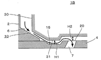
- FIG. 1 shows the overall configuration of a fuel injection valve according to a first embodiment of the present invention.
- the fuel injection valve 1 ⁇ / b> A is configured as an electromagnetically driven fuel injection valve that can be used by being incorporated in a spark ignition type internal combustion engine.
- 1 A of fuel injection valves are equipped with the needle 3 accommodated in the valve body 2 so that reciprocation is possible, and the nozzle hole plate 4 with which the front-end
- the needle 3 is supported by the inner peripheral surface of the valve body 2 and the needle guide 5 in a state where the needle 3 can reciprocate along the direction of the axis Ax.
- the tip 3 a of the needle 3 is configured so that it can be seated and separated from the valve seat 6 formed in the valve body 2.
- a plurality of nozzle holes 7 communicating with the inside and outside of the valve body 2 are formed in the nozzle hole plate 4.
- the proximal end 3 b of the needle 3 is connected to an electromagnetic drive device 11 housed in the valve body 2.
- the electromagnetic drive device 11 includes an armature 12 fixed to the needle 3, an electromagnetic coil 13 that can attract the armature 12 when energized by energization, and a coil spring 14 that biases the needle 3 in a direction to press the valve seat 6. It has.
- the needle 3 is pulled up integrally with the armature 12 from the state in which the needle 3 is pressed against the valve seat 6 by the coil spring 14.
- the needle 3 is separated from the valve seat 6, the fuel flow path 10 is opened, and fuel is injected from the injection hole 7.
- the needle 3 When the energization of the electromagnetic coil 13 is interrupted, the needle 3 is seated on the valve seat 6 by the coil spring 14, thereby closing the fuel flow path 10 and stopping the fuel injection.
- the fuel injection amount and the injection timing can be adjusted by appropriately operating the energization time and timing of the electromagnetic coil 13.
- FIG. 2 is an enlarged cross-sectional view in which the nozzle hole plate 4 and its periphery are enlarged
- FIG. 3 is a plan view showing the nozzle hole plate 4 viewed from the direction of arrow III in FIG.
- the nozzle hole plate 4 is formed with a recess 15 that is recessed in the vertical direction of FIG. 2 (in the direction of the axis Ax in FIG. 1) together with the nozzle hole 7.
- the recess 15 is formed by cutting the nozzle hole plate 4.
- the recess 15 surrounds the plurality of (six in this embodiment) nozzle holes 7 arranged at equal distances from the center C of the nozzle hole plate 4 at equal intervals in the circumferential direction.
- the boundary portions 17 and 18 between the upper surface of the nozzle hole plate 4 and the recess 15 are located in the fuel flow path 10. Therefore, as shown by the arrow line in FIG. 2, the fuel that has passed through the valve seat 6 via the outer periphery of the needle 3 passes through the boundary portion 17 on the valve seat 6 side, and the nozzle hole 7 on the nozzle hole plate 4. It descends below the height of the inlet 20. Then, the lowered fuel flows along the flat bottom portion 21 and then turns upward toward the boundary portion 18 on the injection hole 7 side to reach the inlet 20 of the injection hole 7.
- the flow direction of the fuel can be bent at an acute angle just before the nozzle hole 7 as shown in the drawing, thereby urging the fuel to peel off.
- the fuel flowing along the inner peripheral surface of the nozzle hole 7 can be thinned, so that atomization of the fuel injected from the nozzle hole 7 is promoted.
- the inclination angle must be made considerably larger than the inclination angle ⁇ shown in the figure.
- the formation of the recess 15 can be easily realized by applying a known processing method such as cutting, so that the productivity does not deteriorate.
- the recess 15 since the recess 15 has a shape such that the fuel toward the nozzle hole 7 once falls below the height of the inlet 20 of the nozzle hole 7 on the nozzle hole plate 4, the fuel entering the recess 15 is lowered in the process. Can be disturbed. This can contribute to fuel atomization.
- the recess 15 of the present embodiment is located on the extension of the contact surface 25 between the valve seat 6 and the needle 3 as indicated by the broken line in FIG. Further, the side wall surface 23 connecting the boundary portion 17 and the bottom portion 21 has the same inclination as the contact surface 25. For this reason, since the flow is easily maintained when the fuel that has passed through the valve seat 6 enters the recess 15, a decrease in the fuel flow velocity can be suppressed. Further, most of the fuel entering the recess 15 collides with the bottom 21 of the recess 15 to cause turbulence.
- the position where the disturbance due to the collision occurs can be brought closer to the nozzle hole 7.
- the angle of the side wall surface 24 connecting the boundary 18 and the bottom 21 on the nozzle hole 7 side can be set arbitrarily, and by making it closer to the nozzle hole plate 4 in a vertical direction, peeling can be increased as compared with the illustrated embodiment. Is possible.
- FIG. 1 For the basic configuration of the second embodiment, FIG.
- FIG. 4 is an enlarged cross-sectional view of the nozzle hole plate and its periphery of the fuel injection valve according to the second embodiment.
- the fuel injection valve 1 ⁇ / b> B includes a needle 30, and a protrusion 31 is formed on the needle 30 so as to face the recess 15 and protrude toward the side closer to the injection hole plate 4.
- the amount of protrusion is adjusted so that the protrusion 31 is immersed in the recess 15 when the fuel injection valve 1B is seated, and is positioned at the same height or slightly lower than the upper surface of the nozzle hole plate 4 when the fuel injection valve 1B is seated.
- the fuel injection valve 1 ⁇ / b> B has a protrusion 31 formed on the needle 30, the height H ⁇ b> 1 from the bottom 21 of the recess 15 to the needle 30, and the needle from the upper surface of the injection hole plate 4.
- the height H2 up to 30 can be made uniform. That is, since the protrusion 31 can suppress the expansion of the flow path area due to the provision of the recess 15, it is possible to suppress a decrease in the flow velocity.
- the protrusion 31 has the same shape as that of the recess 15. That is, the protrusion 31 is formed in an annular shape so as to be compatible with the recess 15 shown in FIG. As a result, the above-described uniformity can be achieved at all positions in the circumferential direction.
- a 3rd form is corresponded to what changed a part of the 1st form or the 2nd form, and it has the same composition as these forms about parts other than a changed part. Therefore, the description of the configuration common to the first form or the second form is omitted.
- FIG. 5 is an enlarged cross-sectional view of the nozzle hole plate and its periphery of the fuel injection valve according to the third embodiment
- FIG. 6 shows a state in which the nozzle hole plate shown in FIG. 5 is viewed from the direction of arrow VI.
- the fuel injection valve 1 ⁇ / b> C includes an injection hole plate 32 in which an injection hole 33 is formed, and a groove 34 communicating with the injection hole 33 is formed in the injection hole plate 32.
- the groove 34 communicates with the injection hole 33 on the side close to the center C of the injection hole plate 32. Therefore, a part of the upstream side of the injection hole 33 is cut off.
- the inlet 35 of the nozzle hole 33 is given a height difference ⁇ H that is lower on the side closer to the center of the nozzle hole plate 32 than on the far side.
- the height difference ⁇ H Due to the height difference ⁇ H, as indicated by the arrows in FIGS. 5 and 6, a part of the fuel flowing toward the inlet 35 of the nozzle hole 33 collides with the nozzle hole wall surface near the center C of the nozzle hole plate 32. Can be avoided. By avoiding the collision, it is possible to prevent the fuel from being excessively introduced into the injection hole 33, so that the thinning of the fuel injected from the outlet 36 of the injection hole 33 can be promoted. This facilitates atomization of the fuel.
- the height difference ⁇ H is given by processing the groove 34, it is relatively easy to give a high precision height difference.
- the formation of the groove 34 to give the height difference ⁇ H is an example. For example, by cutting the central portion of the nozzle hole plate 32 so as to interfere with the nozzle hole 33, the same height as the nozzle hole 33 is formed. It is also possible to give a difference.
- the present invention is not limited to the above embodiments, and can be implemented in various forms.
- the nozzle hole plate in which the nozzle holes and the recesses are formed as described below, and it is possible to implement the present invention by applying these to the above-described embodiments.
- the number of injection holes formed in the injection hole plate is six, and these injection holes are Although arranged in the circumferential direction at equal distances from the center of the nozzle hole plate, as shown in FIGS. 7A to 7I, the number of nozzle holes and their arrangement are changed to match the arrangement of these nozzle holes.
- the shape of the recess and its arrangement can be changed respectively.
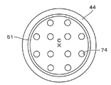
- FIG. 7A is a plan view showing a first modified example related to the nozzle hole plate.
- the number of nozzle holes 71 formed in the nozzle hole plate 41 is twelve, and four nozzle holes 71 are arranged in the center C as an inner nozzle hole group on the side close to the center C of the nozzle hole plate 41.
- the eight nozzle holes 71 are arranged in the circumferential direction at equal distances from the center C, and are arranged in the circumferential direction at the same distance from the center, and as the outer nozzle hole groups on the outside of the inner nozzle hole group.
- An annular recess 50 extending in an annular shape is disposed between and an annular recess 51 is disposed outside the outer nozzle hole group.
- FIG. 7B is a plan view showing a second modification regarding the nozzle hole plate.
- the number of injection holes 72 formed in the injection hole plate 42 in the second modification example is increased to 18 as compared with the first modification example.
- the number of nozzle holes 72 in the inner nozzle hole group is set to six
- the number of nozzle holes 72 in the outer nozzle hole group is set to twelve.
- two annular recesses 50 and 51 are arranged as in the first modification example of FIG. 7A.
- FIG. 7C is a plan view showing a third modification regarding the nozzle hole plate.
- the injection holes 73 are arranged in the injection hole plate 43 as in the first modified example.
- the annular recess 50 is disposed in the nozzle hole plate 43 only between the two.
- FIG. 7D is a plan view showing a fourth modification regarding the nozzle hole plate.
- the nozzle hole 74 is arranged in the nozzle hole plate 44 as in the first modified example, but the concave part is formed only on the outer side of the outer nozzle hole group. 51 is arranged on the nozzle hole plate 44.
- the shape of the recess is annular and surrounds the injection hole. Therefore, the recess is not in contact with all the fuel toward the injection hole arranged at the center side of the recess. Can give an effect.
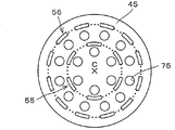
- FIG. 7E is a plan view showing a fifth modification regarding the nozzle hole plate.
- 12 injection holes 75 are arranged in the injection hole plate 45 as in the second modified example, but the form of the recesses is different. That is, in the fifth modification, the recesses are not annular, and the split recesses 55 and 56 that intermittently extend in the circumferential direction in a state of facing the respective injection holes 75 are provided between the inner injection hole group and the outer injection hole group. And on the outside of the outer nozzle hole group.
- FIG. 7F is a plan view showing a sixth modification related to the nozzle hole plate.
- the sixth modified example is similar to the fifth modified example, but the recess disposed between the inner nozzle hole group and the outer nozzle group is an annular recess 50 similar to the first modified example, and the annular The point which formed the recessed part 50 in the nozzle hole plate 46 is different from a modification.
- the number of nozzle holes 76 and their arrangement are the same as in the fifth modification.
- the dividing concave portion 56 arranged outside the outer nozzle hole group is divided at a position indicated by a broken line except for a portion facing each nozzle hole of the outer nozzle hole group. Therefore, the fuel guided to the inner nozzle hole group passes through the divided portion and reaches the inner nozzle hole group through the divided concave portion 55 or the annular concave portion 50 without being influenced by the divided concave portion 56. Therefore, since the atomization effect of the fuel by the inner nozzle hole group is not deteriorated as compared with the case of the outer nozzle hole group, the atomization effect of each of the inner nozzle hole group and the outer nozzle hole group can be made uniform.
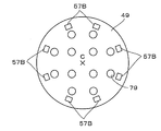
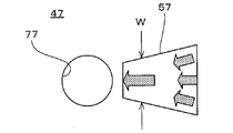
- FIG. 7G is a plan view showing a seventh modification regarding the nozzle hole plate.
- 12 nozzle holes 77 are formed in the nozzle hole plate 47 in the same manner as in the first modified example, and are adjacent to each of the nozzle holes 77 included in the inner nozzle hole group.
- the second recess 57B is arranged in the nozzle hole plate 47 so that the elongated first recess 57A is adjacent to each of the nozzle holes 77 included in the outer nozzle hole group.
- the direction of each of the recesses 57 ⁇ / b> A and 57 ⁇ / b> B is set so as to go to the center C of the nozzle hole plate 47.
- the effects of the recesses 57A and 57B can be equally applied to the nozzle holes 77 formed in the nozzle hole plate 47.
- the first recess 57A adjacent to each nozzle hole 77 of the inner nozzle hole group is formed in an elongated rectangular shape having a length in the radial direction larger than a width in the circumferential direction of the nozzle hole plate 47. The fuel can be efficiently guided to the respective injection holes 77 of the inner injection hole group that is far from the valve seat.
- FIG. 7H is a plan view showing an eighth modification regarding the nozzle hole plate.
- the eighth modification the second recess 57B adjacent to the outer injection hole group is omitted from the seventh modification, and the first recess 57A adjacent to the inner injection hole group is formed in the injection hole plate 48. is there.
- the number and arrangement of the nozzle holes 78 are the same as in the seventh modification.
- FIG. 7I is a plan view showing a ninth modification regarding the nozzle hole plate.
- the ninth modification the first recess 57A adjacent to the inner injection hole group is omitted from the seventh modification, and the second recess 57B adjacent to the outer injection hole group is formed in the injection hole plate 49. is there.
- the number and arrangement of the nozzle holes 79 are the same as in the seventh modification.
- the eighth and ninth modified examples can exhibit the same effects as the seventh modified example.
- the shape of the recess 57 is gradually increased as the width W in the circumferential direction of the injection hole plate 47 approaches the injection hole 77. It is also possible to make it narrower.
- the fuel that has entered the recess 57 is gradually throttled toward the nozzle hole, so that the flow of fuel toward the nozzle hole 77 can be enhanced. Thereby, the force which presses a fuel to the inner wall face of the nozzle hole 77 becomes large, and it can contribute to the thin film formation of the fuel.
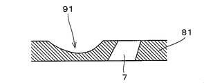
- FIG. 10A is an enlarged cross-sectional view showing a first modified example related to the recess.
- a concave portion 91 is formed in the nozzle hole plate 81, and the concave portion 91 has an arc shape in the cross section.
- the arc portion may be a part of a circle, a part of an ellipse, a part of another curve, or a combination of these.
- FIG. 10B is an enlarged cross-sectional view showing a second modified example related to the recess.
- a recess 92 is formed in the nozzle hole plate 82, and the recess 92 has a triangular shape that appears in the cross section.
- the corners or corners of the recesses 92 may be rounded.
- the straight part is provided between the recess and the injection hole.
- the presence or absence of this straight part and the shape of the straight part viewed from the axial direction. Is optional, and can be implemented with variations described below.
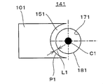
- FIG. 11A is a plan view showing a first modification example regarding the straight portion.
- the concave portion 101 according to this modification is formed in the nozzle hole plate 141 such that the contour P1 on the nozzle hole 171 side formed between the upper surface of the nozzle hole plate 141 is in a shape along the inlet 181 of the nozzle hole 171.
- the length L1 of the straight portion 151 is uniform in the circumferential direction of the inlet 181. That is, the center C ⁇ b> 1 that gives the contour P coincides with the center of the nozzle hole 171.
- FIG. 11B is a plan view showing a second modification regarding the straight portion.
- the outline P2 on the side of the injection hole 172 formed between the upper surface of the injection hole plate 142 and the inlet 182 of the injection hole 172 is formed, as in the first modification. In this way, the nozzle hole plate 142 is formed.
- the length L2 of the straight portion 152 changes so as to be the maximum value at both end portions and the minimum value at the center portion in the circumferential direction.
- the recess 102 is formed so that the center C2 that gives the contour P2 is located on the wall surface on the opposite side of the injection hole 172.
- the contour of the recess is shaped along the inlet of the nozzle hole. Therefore, when the fuel that has passed through the recess reaches the inlet of the nozzle hole, the circumferential direction of the nozzle hole Under almost the same conditions, the fuel can be peeled off reliably.
- FIG. 11C is a plan view showing a third modification example regarding the straight portion.
- the feature of this modification is that the recess 103 is formed in the nozzle hole plate 143 so that the boundary 110 between the upper surface of the nozzle hole plate 143 and the recess 103 overlaps the inlet 183 of the nozzle hole 173 in order to eliminate the straight part. is doing.
- the portion A where fuel separation occurs is sharp, that is, the separation angle ⁇ 1 is large and the angle ⁇ 2 of the portion A is an acute angle. Is strengthened and fuel atomization is further improved.
- FIG. 13A is an explanatory view showing a first example in which a plurality of recesses are provided for one nozzle hole.
- a plurality of (three in the figure) recesses 105 are provided for one injection hole 175, and each recess 105 extends toward the injection hole 175.
- FIG. 13B is an explanatory view showing a second example in which a plurality of recesses are provided for one nozzle hole.
- a plurality (two in the figure) of recesses 106 are provided so as to extend toward one nozzle hole 176 and each recess 106 is close to the nozzle hole 176. Connected on the side.
- fuel that does not flow toward the inlet of the nozzle hole can be concentrated in the nozzle hole by a plurality of recesses. Therefore, fuel can be injected efficiently.
- the direction of the injection hole formed in the injection hole plate does not necessarily have to be inclined with respect to the traveling direction of the fuel.
- the inclination angle ⁇ shown in FIG. 2 may be 0, that is, the injection hole may be formed perpendicular to the injection hole plate.
Abstract
Description
図1は本発明の第1の形態に係る燃料噴射弁の全体構成を示している。燃料噴射弁1Aは火花点火型の内燃機関に組み込まれて使用可能な電磁駆動式の燃料噴射弁として構成されている。燃料噴射弁1Aは、バルブボディ2の内部に往復動可能な状態で収納されたニードル3と、バルブボディ2の先端部2aに装着された噴孔プレート4とを備えている。ニードル3は、軸線Ax方向に沿って往復運動可能な状態でバルブボディ2の内周面とニードルガイド5とによって支持されている。ニードル3の先端部3aはバルブボディ2に形成されたバルブシート6に対して着座及び離座できるように構成されている。噴孔プレート4にはバルブボディ2の内外に通じる複数個の噴孔7が形成されている。ニードル3がバルブシート6に対して離座及び着座することにより、ニードル3の外周を経由して噴孔7に至る燃料流路10を閉鎖及び開通することができる。ニードル3の基端部3bはバルブボディ2に収納された電磁駆動装置11に接続されている。 (First form)
FIG. 1 shows the overall configuration of a fuel injection valve according to a first embodiment of the present invention. The
次に、本発明の第2の形態を図4を参照しながら説明する。第2の形態はニードルの形状を除いて第1の形態と共通する。そのため、第1の形態と共通する構成については図面に同一の符号を付して説明を省略する。また、第2の形態の基本的構成については図1等が適宜参照される。 (Second form)
Next, a second embodiment of the present invention will be described with reference to FIG. The second form is common to the first form except for the shape of the needle. Therefore, the same reference numerals are given to the configurations common to the first embodiment, and description thereof is omitted. For the basic configuration of the second embodiment, FIG.
次に、本発明の第3の形態を図5及び図6を参照しながら説明する。第3の形態は第1の形態又は第2の形態の一部を変更したものに相当し、変更点以外の部分についてはこれらの形態と共通の構成を有している。従って、第1の形態又は第2の形態と共通する構成については説明を省略する。 (Third form)
Next, a third embodiment of the present invention will be described with reference to FIGS. A 3rd form is corresponded to what changed a part of the 1st form or the 2nd form, and it has the same composition as these forms about parts other than a changed part. Therefore, the description of the configuration common to the first form or the second form is omitted.
本発明は以上の各形態に限定されるものではなく種々の形態にて実施できる。例えば、噴孔及び凹部等が形成される噴孔プレートに関しては以下に説明するように種々のバリエーションが存在し、これらを上記各形態に適用して本発明を実施することも可能である。 (Modification)
The present invention is not limited to the above embodiments, and can be implemented in various forms. For example, there are various variations of the nozzle hole plate in which the nozzle holes and the recesses are formed as described below, and it is possible to implement the present invention by applying these to the above-described embodiments.
上述した第1~第3の形態では、噴孔プレートに形成される噴孔の個数が6個であり、かつそれらの噴孔が噴孔プレートの中心から等距離で周方向に並べられたものであるが、図7A~図7Iに示すように、噴孔の個数及びその配置形態を変更し、これら噴孔の配置形態に合わせて凹部の形状及びその配置をそれぞれ変更できる。 (1) Modifications Regarding Arrangement of Injection Holes and Recesses of Injection Hole Plate In the first to third embodiments described above, the number of injection holes formed in the injection hole plate is six, and these injection holes are Although arranged in the circumferential direction at equal distances from the center of the nozzle hole plate, as shown in FIGS. 7A to 7I, the number of nozzle holes and their arrangement are changed to match the arrangement of these nozzle holes. The shape of the recess and its arrangement can be changed respectively.
図7Aは噴孔プレートに関する第1の変形例を示した平面図である。第1の変形例は、噴孔プレート41に形成される噴孔71の個数を12個とし、噴孔プレート41の中心Cに近い側に内側噴孔群として4個の噴孔71を中心Cから等距離に周方向に並べ、かつ内側噴孔群の外側に外側噴孔群として8個の噴孔71を中心Cから等距離に周方向に並べるとともに、内側噴孔群と外側噴孔群との間に環状に延びる環状凹部50を配置しかつ外側噴孔群の外側に環状凹部51を配置したものである。 (First modification)
FIG. 7A is a plan view showing a first modified example related to the nozzle hole plate. In the first modification, the number of nozzle holes 71 formed in the nozzle hole plate 41 is twelve, and four nozzle holes 71 are arranged in the center C as an inner nozzle hole group on the side close to the center C of the nozzle hole plate 41. The eight nozzle holes 71 are arranged in the circumferential direction at equal distances from the center C, and are arranged in the circumferential direction at the same distance from the center, and as the outer nozzle hole groups on the outside of the inner nozzle hole group. An
図7Bは噴孔プレートに関する第2の変形例を示した平面図である。図7Bから明らかなように、第2の変形例は第1の変形例と比較して噴孔プレート42に形成される噴孔72の個数が18個に増えている。具体的には内側噴孔群の噴孔72の個数が6個に、外側噴孔群の噴孔72の個数が12個にそれぞれ設定されている。凹部としては、図7Aの第1の変形例と同じく2つの環状凹部50、51がそれぞれ配置されている。 (Second modification)
FIG. 7B is a plan view showing a second modification regarding the nozzle hole plate. As is apparent from FIG. 7B, the number of injection holes 72 formed in the
図7Cは噴孔プレートに関する第3の変形例を示した平面図である。図7Cから明らかなように、第3の変形例は第1の変形例と同様に噴孔73が噴孔プレート43に配置されているが、凹部については内側噴孔群と外側噴孔群との間のみに環状凹部50が噴孔プレート43に配置されている。 (Third Modification)
FIG. 7C is a plan view showing a third modification regarding the nozzle hole plate. As apparent from FIG. 7C, in the third modified example, the injection holes 73 are arranged in the
図7Dは噴孔プレートに関する第4の変形例を示した平面図である。図7Dから明らかなように、第4の変形例は第1の変形例と同様に噴孔74が噴孔プレート44に配置されているが、凹部については外側噴孔群の外側のみに環状凹部51が噴孔プレート44に配置されている。 (Fourth modification)
FIG. 7D is a plan view showing a fourth modification regarding the nozzle hole plate. As is apparent from FIG. 7D, in the fourth modified example, the
図7Eは噴孔プレートに関する第5の変形例を示した平面図である。第5の変形例は、第2の変形例と同様に12個の噴孔75が噴孔プレート45に配置されているが、凹部についてはその形態が異なっている。即ち、第5の変形例は、凹部が環状ではなく、各噴孔75と対向した状態で周方向に断続的に延びる分断凹部55、56が、内側噴孔群と外側噴孔群との間及び外側噴孔群の外側のそれぞれに配置されている。 (Fifth modification)
FIG. 7E is a plan view showing a fifth modification regarding the nozzle hole plate. In the fifth modified example, 12 injection holes 75 are arranged in the
図7Fは噴孔プレートに関する第6の変形例を示した平面図である。第6の変形例は、第5の変形例に類似するが、内側噴孔群と外側噴孔群との間に配置される凹部を第1の変形例と同様の環状凹部50とし、その環状凹部50を噴孔プレート46に形成した点が変形例と相違する。噴孔76の個数及びそれらの配置は第5の変形例と同一である。 (Sixth Modification)
FIG. 7F is a plan view showing a sixth modification related to the nozzle hole plate. The sixth modified example is similar to the fifth modified example, but the recess disposed between the inner nozzle hole group and the outer nozzle group is an
図7Gは噴孔プレートに関する第7の変形例を示した平面図である。第7の変形例は、第1の変形例と同様に噴孔プレート47に12個の噴孔77を形成し、内側噴孔群に含まれる噴孔77のぞれぞれに隣接するようにして細長の第1の凹部57Aを、外側噴孔群に含まれる噴孔77のそれぞれに隣接するようにして第2の凹部57Bを噴孔プレート47に配置したものである。各凹部57A、57Bの向きは噴孔プレート47の中心Cに向かうように設定されている。各凹部57A、57Bの向きが中心Cに向かっているので、噴孔プレート47に形成された各噴孔77に対して均等に凹部57A、57Bによる効果を与えることができる。また、内側噴孔群の各噴孔77に隣接する第1の凹部57Aは、噴孔プレート47の周方向に関する幅よりも半径方向に関する長さが大きい細長の矩形状に形成されているので、バルブシートからの距離が遠い内側噴孔群の各噴孔77に効率的に燃料を導くことができる。 (Seventh Modification)
FIG. 7G is a plan view showing a seventh modification regarding the nozzle hole plate. In the seventh modified example, 12 nozzle holes 77 are formed in the
図7Hは噴孔プレートに関する第8の変形例を示した平面図である。第8の変形例は第7の変形例から外側噴孔群に隣接する第2の凹部57Bを省略し、内側噴孔群に隣接する第1の凹部57Aを噴孔プレート48に形成したものである。噴孔78の個数及び配置は第7の変形例と同じである。 (Eighth modification)
FIG. 7H is a plan view showing an eighth modification regarding the nozzle hole plate. In the eighth modification, the
図7Iは噴孔プレートに関する第9の変形例を示した平面図である。第9の変形例は第7の変形例から内側噴孔群に隣接する第1の凹部57Aを省略し、外側噴孔群に隣接する第2の凹部57Bを噴孔プレート49に形成したものである。噴孔79の個数及び配置は第7の変形例と同じである。第8及び第9の変形例は第7の変形例と同様の効果を発揮することができる。 (Ninth Modification)
FIG. 7I is a plan view showing a ninth modification regarding the nozzle hole plate. In the ninth modification, the
上述した第1~第3の各形態において、燃料の流れ方向(半径方向)と平行でかつ噴孔プレートに垂直な断面に現れる凹部の形状は図2に示した底部が平坦な台形状であるが、これは一例にすぎない。噴孔に向かう燃料に対して、バルブシートを通過してから噴孔プレート上で噴孔の入口の高さよりも下降してから上昇に転じて噴孔の入口に至るように流れ方向を変更できる限りにおいて以下に説明するバリエーションで凹部を形成してよい。 (2) Modification regarding cross-sectional shape of recess In each of the first to third embodiments described above, the shape of the recess appearing in a cross section parallel to the fuel flow direction (radial direction) and perpendicular to the nozzle hole plate is shown in FIG. The bottom shown is a flat trapezoid, but this is only an example. The flow direction of the fuel going to the nozzle hole can be changed so that it passes through the valve seat and then falls below the height of the nozzle hole inlet on the nozzle hole plate and then rises to reach the nozzle hole inlet. Insofar as possible, the recesses may be formed by variations described below.
図10Aは凹部に関する第1の変形例を示した拡大断面図である。第1の変形例は噴孔プレート81に凹部91が形成されており、その凹部91は、上記断面に現れる形状が弧状となっている。なお、この弧の部分は、円の一部でも、楕円の一部あるいは他の曲線の一部でも、これらが組み合わされたものでもよい。 (First modification)
FIG. 10A is an enlarged cross-sectional view showing a first modified example related to the recess. In the first modification, a
図10Bは凹部に関する第2の変形例を示した拡大断面図である。第2の変形例は噴孔プレート82に凹部92が形成されており、その凹部92は、上記断面に現れる形状が三角形状となっている。この場合、凹部92の隅部又は角部には丸みを与えてもよい。 (Second modification)
FIG. 10B is an enlarged cross-sectional view showing a second modified example related to the recess. In the second modification, a
上述した第1~第3の形態では、凹部と噴孔との間にストレート部を設けているが、こストレート部の存否及びストレート部を軸線方向から見た形状は任意であり、以下に説明するバリエーションで実施可能である。 (3) Modification concerning straight part In the first to third embodiments described above, the straight part is provided between the recess and the injection hole. The presence or absence of this straight part and the shape of the straight part viewed from the axial direction. Is optional, and can be implemented with variations described below.
図11Aはストレート部に関する第1の変形例を示した平面図である。この変形例に係る凹部101は、噴孔プレート141の上面との間に形成される噴孔171側の輪郭P1が噴孔171の入口181に沿う形状となるように噴孔プレート141に形成されている。第1の変形例は、ストレート部151の長さL1が入口181の周方向に関して均一になっている。即ち、輪郭Pを与える中心C1が噴孔171の中心に一致している。 (First modification)
FIG. 11A is a plan view showing a first modification example regarding the straight portion. The
図11Bはストレート部に関する第2の変形例を示した平面図である。この変形例に係る凹部102は、第1の変形例と同様に、噴孔プレート142の上面との間に形成される噴孔172側の輪郭P2が噴孔172の入口182に沿う形状となるように噴孔プレート142に形成されている。第2の変形例は、ストレート部152の長さL2が周方向に関して、両端部で最大値となり中央部で最小値となるように変化している。ストレート部142の長さL2をこのように変化させるため、輪郭P2を与える中心C2が噴孔172の対向側の壁面に位置するように凹部102が形成されている。 (Second modification)
FIG. 11B is a plan view showing a second modification regarding the straight portion. In the
図11Cはストレート部に関する第3の変形例を示した平面図である。この変形例の特徴は上記のストレート部を無くすため、噴孔プレート143の上面と凹部103との境界部110と、噴孔173の入口183とが重なるように凹部103を噴孔プレート143に形成している。この変形例によれば、図12に示すように、燃料の剥離が生じる部分Aが尖った形状、つまり剥離角度θ1が大きく、かつ部分Aの角度θ2が鋭角となる形状になるので燃料の剥離が強化され燃料の微粒化が一層向上する。 (Third Modification)
FIG. 11C is a plan view showing a third modification example regarding the straight portion. The feature of this modification is that the
本発明は、一つの噴孔に対して一つの凹部が設けられる場合に限らず、一つの噴孔に対して複数個の凹部が設けられてもよい。図13Aは、一つの噴孔に対して複数個の凹部を設ける第1の例を示した説明図である。この第1の例は、一つの噴孔175に対して複数個(図では3個)の凹部105が設けられており、各凹部105は噴孔175に向かって延びている。図13Bは、一つの噴孔に対して複数個の凹部を設ける第2の例を示した説明図である。この第2の例は、一つの噴孔176に対して複数個(図では2個)の凹部106が噴孔に向かって延びるように設けられており、かつ各凹部106が噴孔176に近い側で繋がっている。図13A及び図13Bに示した各例は、噴孔の入口に向かって流れていない燃料を複数の凹部によってその噴孔に集約することができる。そのため、燃料を効率良く噴射させることができる。 (4) Other Modifications The present invention is not limited to the case where one recess is provided for one nozzle hole, and a plurality of recesses may be provided for one nozzle hole. FIG. 13A is an explanatory view showing a first example in which a plurality of recesses are provided for one nozzle hole. In this first example, a plurality of (three in the figure) recesses 105 are provided for one
Claims (18)
- バルブボディに往復動可能な状態で収納されたニードルと、前記バルブボディの先端部に装着され、前記バルブボディの内外に通じる噴孔が形成された噴孔プレートと、前記ニードルの外周を経由して前記噴孔プレートの前記噴孔に至る燃料流路を閉鎖及び開通できるように前記ニードルが着座及び離座するバルブシートと、を備え、
前記噴孔プレートには、前記バルブシートを通過して前記噴孔に向かう燃料が前記噴孔プレート上で前記噴孔の入口の高さよりも下降してから上昇に転じて前記噴孔の入口に至るように、前記ニードルの軸線方向に関して凹んだ凹部が形成されている燃料噴射弁。 A needle housed in a reciprocable state in the valve body, an injection hole plate attached to the tip of the valve body and formed with an injection hole communicating with the inside and outside of the valve body, and an outer periphery of the needle And a valve seat on which the needle is seated and separated so that the fuel flow path leading to the nozzle hole of the nozzle hole plate can be closed and opened,
In the nozzle hole plate, the fuel passing through the valve seat and heading toward the nozzle hole is lowered from the height of the inlet of the nozzle hole on the nozzle hole plate and then rises to the inlet of the nozzle hole. A fuel injection valve in which a recessed portion that is recessed with respect to the axial direction of the needle is formed. - 前記噴孔プレートには、その中心から半径方向外側に離れた位置に前記噴孔が形成されており、
前記噴孔の前記入口には、前記中心に近い側が前記中心から遠い側よりも低い高低差が与えられている、請求項1に記載の燃料噴射弁。 The nozzle hole is formed in the nozzle hole plate at a position spaced radially outward from the center thereof,
2. The fuel injection valve according to claim 1, wherein the inlet of the nozzle hole is provided with a height difference that is lower on a side closer to the center than on a side farther from the center. - 前記中心に近い側で前記噴孔に通じる溝が前記噴孔プレートに形成されることにより前記高低差が与えられている、請求項2に記載の燃料噴射弁。 The fuel injection valve according to claim 2, wherein the height difference is given by forming a groove communicating with the injection hole on the side close to the center in the injection hole plate.
- 前記バルブシートと前記ニードルとの接触面の延長上に、前記噴孔プレートの上面と前記凹部との境界部が位置するように前記凹部が配置されている、請求項1~3のいずれか一項に記載の燃料噴射弁。 The concave portion is arranged such that a boundary portion between the upper surface of the nozzle hole plate and the concave portion is positioned on an extension of a contact surface between the valve seat and the needle. The fuel injection valve according to Item.
- 前記凹部は前記境界部と底部とを繋ぐ側壁面を有し、前記接触面と前記側壁面とが同一の傾きを有している、請求項4に記載の燃料噴射弁。 The fuel injection valve according to claim 4, wherein the concave portion has a side wall surface connecting the boundary portion and the bottom portion, and the contact surface and the side wall surface have the same inclination.
- 前記凹部と前記噴孔とが所定距離隔てて前記噴孔プレートに配置されることにより、前記凹部と前記噴孔との間にストレート部が形成されている、請求項1~5のいずれか一項に記載の燃料噴射弁。 The straight portion is formed between the concave portion and the nozzle hole by disposing the concave portion and the nozzle hole on the nozzle plate at a predetermined distance. The fuel injection valve according to Item.
- 前記噴孔プレートには、前記噴孔が複数個形成されており、
前記凹部は、複数個の前記噴孔を取り囲むように前記噴孔プレートの周方向に延びている、請求項1~6のいずれか一項に記載の燃料噴射弁。 The nozzle hole plate is formed with a plurality of the nozzle holes,
The fuel injection valve according to any one of claims 1 to 6, wherein the recess extends in a circumferential direction of the nozzle hole plate so as to surround the plurality of nozzle holes. - 前記噴孔プレートには、前記噴孔プレートの周方向に前記噴孔が複数個並べられた内側噴孔群と、前記内側噴孔群の外側に周方向に前記噴孔が複数個並べられた外側噴孔群とが形成されており、
前記凹部として、前記噴孔プレートの周方向に延びるようにして前記内側噴孔群と前記外側噴孔群との間に配置され、前記内側噴孔群の各噴孔と対向した状態で周方向に断続的に延びる第1の分断凹部と、前記外側噴孔群の外側に、前記外側噴孔群の各噴孔と対向した状態で周方向に断続的に延びる第2の分断凹部とが設けられている、請求項1~6のいずれか一項に記載の燃料噴射弁。 In the nozzle hole plate, an inner nozzle hole group in which a plurality of the nozzle holes are arranged in the circumferential direction of the nozzle hole plate, and a plurality of nozzle holes in the circumferential direction are arranged outside the inner nozzle hole group. An outer nozzle hole group is formed,
The concave portion is disposed between the inner nozzle hole group and the outer nozzle hole group so as to extend in the circumferential direction of the nozzle hole plate, and in the circumferential direction in a state facing each nozzle hole of the inner nozzle hole group. And a second dividing recess extending intermittently in the circumferential direction in a state of facing the respective injection holes of the outer injection hole group, provided outside the outer injection hole group. The fuel injection valve according to any one of claims 1 to 6, wherein: - 前記噴孔プレートには、前記噴孔プレートの周方向に前記噴孔が複数個並べられた内側噴孔群と、前記内側噴孔群の外側に周方向に前記噴孔が複数個並べられた外側噴孔群とが形成されており、
前記凹部として、前記噴孔プレートの周方向に延びるようにして前記内側噴孔群と前記外側噴孔群との間に配置された環状凹部と、前記外側噴孔群の外側に、各噴孔と対向した状態で周方向に断続的に延びる分断凹部とが設けられている、請求項1~6のいずれか一項に記載の燃料噴射弁。 In the nozzle hole plate, an inner nozzle hole group in which a plurality of the nozzle holes are arranged in the circumferential direction of the nozzle hole plate, and a plurality of nozzle holes in the circumferential direction are arranged outside the inner nozzle hole group. An outer nozzle hole group is formed,
As the recess, an annular recess disposed between the inner nozzle hole group and the outer nozzle hole group so as to extend in the circumferential direction of the nozzle hole plate, and each nozzle hole outside the outer nozzle hole group. The fuel injection valve according to any one of claims 1 to 6, further comprising a split concave portion extending intermittently in a circumferential direction in a state of being opposed to each other. - 前記噴孔プレートには、前記噴孔が複数個形成されており、
前記凹部は、各噴孔に隣接して配置され、かつその向きが前記噴孔プレートの中心に向かうように設定されている、請求項1~6のいずれか一項に記載の燃料噴射弁。 The nozzle hole plate is formed with a plurality of the nozzle holes,
The fuel injection valve according to any one of claims 1 to 6, wherein the concave portion is disposed adjacent to each nozzle hole and set so that the direction thereof is directed toward a center of the nozzle hole plate. - 前記凹部は、前記噴孔プレートの周方向に関する幅よりも半径方向に関する長さが大きくなるように前記噴孔プレートの中心に向かって延びている、請求項1~6のいずれか一項に記載の燃料噴射弁。 The concave portion extends toward the center of the nozzle hole plate so that the length in the radial direction is larger than the width in the circumferential direction of the nozzle hole plate. Fuel injection valve.
- 前記ニードルには、前記噴孔プレートに形成された前記凹部に対向し、かつ前記凹部に接近する側に突出する突部が形成されている、請求項1~11のいずれか一項に記載の燃料噴射弁。 The protrusion according to any one of claims 1 to 11, wherein the needle is formed with a protrusion that faces the recess formed in the nozzle hole plate and protrudes toward the side approaching the recess. Fuel injection valve.
- 前記突部は、対向する前記凹部と同様の形状を有している、請求項12に記載の燃料噴射弁。 The fuel injection valve according to claim 12, wherein the protrusion has a shape similar to that of the opposing recess.
- 前記凹部は、前記噴孔プレートの上面との間に形成される前記噴孔側の輪郭が前記噴孔の前記入口に沿う形状となるように前記噴孔プレートに形成されている、請求項1~6のいずれか一項に記載の燃料噴射弁。 The said recessed part is formed in the said nozzle hole plate so that the outline of the said nozzle hole side formed between the upper surfaces of the said nozzle hole plate may become a shape along the said inlet_port | entrance of the said nozzle hole. The fuel injection valve according to any one of 1 to 6.
- 前記凹部は、前記噴孔プレートの周方向に関する幅が前記噴孔に近づくに従って徐々に狭くなるように前記噴孔プレートに形成されている、請求項1~6のいずれか一項に記載の燃料噴射弁。 The fuel according to any one of claims 1 to 6, wherein the recess is formed in the nozzle hole plate such that a width in a circumferential direction of the nozzle hole plate gradually decreases as the nozzle hole approaches the nozzle hole. Injection valve.
- 前記凹部は、前記噴孔プレートに一つの前記噴孔に対して複数個形成されており、
複数個の前記凹部のそれぞれは前記噴孔に向かって延びている、請求項1~6のいずれか一項に記載の燃料噴射弁。 A plurality of the recesses are formed for one nozzle hole in the nozzle hole plate,
The fuel injection valve according to any one of claims 1 to 6, wherein each of the plurality of recesses extends toward the injection hole. - 複数個の前記凹部のそれぞれが前記噴孔に近い側で繋がっている、請求項16に記載の燃料噴射弁。 The fuel injection valve according to claim 16, wherein each of the plurality of recesses is connected on a side close to the injection hole.
- 前記凹部は、前記噴孔プレートの上面と前記凹部との境界部と、前記噴孔の前記入口とが重なるようにして前記噴孔プレートに形成されている、請求項1~3のいずれか一項に記載の燃料噴射弁。 The concave portion is formed in the nozzle plate such that a boundary portion between the upper surface of the nozzle plate and the concave portion and the inlet of the nozzle hole overlap each other. The fuel injection valve according to Item.
Priority Applications (5)
| Application Number | Priority Date | Filing Date | Title |
|---|---|---|---|
| US13/578,908 US8794550B2 (en) | 2010-03-05 | 2010-03-05 | Fuel injection valve |
| CN201080063742.9A CN102906414B (en) | 2010-03-05 | 2010-03-05 | Fuel injection valve |
| JP2012502953A JP5299557B2 (en) | 2010-03-05 | 2010-03-05 | Fuel injection valve |
| EP10847020.4A EP2543872B1 (en) | 2010-03-05 | 2010-03-05 | Fuel injection valve |
| PCT/JP2010/053679 WO2011108118A1 (en) | 2010-03-05 | 2010-03-05 | Fuel injection valve |
Applications Claiming Priority (1)
| Application Number | Priority Date | Filing Date | Title |
|---|---|---|---|
| PCT/JP2010/053679 WO2011108118A1 (en) | 2010-03-05 | 2010-03-05 | Fuel injection valve |
Publications (1)
| Publication Number | Publication Date |
|---|---|
| WO2011108118A1 true WO2011108118A1 (en) | 2011-09-09 |
Family
ID=44541802
Family Applications (1)
| Application Number | Title | Priority Date | Filing Date |
|---|---|---|---|
| PCT/JP2010/053679 WO2011108118A1 (en) | 2010-03-05 | 2010-03-05 | Fuel injection valve |
Country Status (5)
| Country | Link |
|---|---|
| US (1) | US8794550B2 (en) |
| EP (1) | EP2543872B1 (en) |
| JP (1) | JP5299557B2 (en) |
| CN (1) | CN102906414B (en) |
| WO (1) | WO2011108118A1 (en) |
Families Citing this family (7)
| Publication number | Priority date | Publication date | Assignee | Title |
|---|---|---|---|---|
| CN104520577B (en) * | 2012-08-09 | 2018-01-23 | 三菱电机株式会社 | Fuelinjection nozzle |
| US9470197B2 (en) * | 2012-12-21 | 2016-10-18 | Caterpillar Inc. | Fuel injector having turbulence-reducing sac |
| JP2016205197A (en) * | 2015-04-21 | 2016-12-08 | 日立オートモティブシステムズ株式会社 | Fuel injection device |
| US10724486B2 (en) * | 2018-03-21 | 2020-07-28 | Delphi Technologies Ip Limited | Fluid injector having a director plate |
| JP7167663B2 (en) * | 2018-11-28 | 2022-11-09 | 株式会社デンソー | fuel injector |
| JP7272645B2 (en) * | 2019-06-20 | 2023-05-12 | 株式会社デンソー | fuel injector |
| CN114522817A (en) * | 2022-04-21 | 2022-05-24 | 山西海普瑞科技有限公司 | Nozzle structure for preventing high-pressure water jet from being damaged |
Citations (8)
| Publication number | Priority date | Publication date | Assignee | Title |
|---|---|---|---|---|
| JPH0932695A (en) | 1995-07-24 | 1997-02-04 | Toyota Motor Corp | Fuel injection valve |
| JP2002227748A (en) * | 2001-01-30 | 2002-08-14 | Unisia Jecs Corp | Fuel injection valve |
| JP2005155547A (en) * | 2003-11-27 | 2005-06-16 | Mitsubishi Electric Corp | Fuel injection valve |
| JP2005282420A (en) * | 2004-03-29 | 2005-10-13 | Denso Corp | Fuel injection valve |
| JP2007182767A (en) * | 2006-01-05 | 2007-07-19 | Hitachi Ltd | Fuel injection valve |
| JP2007309236A (en) | 2006-05-19 | 2007-11-29 | Toyota Motor Corp | Fuel injection nozzle |
| JP2008121517A (en) | 2006-11-10 | 2008-05-29 | Toyota Motor Corp | Fuel injection valve of internal combustion engine |
| WO2008117459A1 (en) * | 2007-03-27 | 2008-10-02 | Mitsubishi Electric Corporation | Fuel injection valve |
Family Cites Families (10)
| Publication number | Priority date | Publication date | Assignee | Title |
|---|---|---|---|---|
| US5383597A (en) * | 1993-08-06 | 1995-01-24 | Ford Motor Company | Apparatus and method for controlling the cone angle of an atomized spray from a low pressure fuel injector |
| US6817545B2 (en) * | 2002-01-09 | 2004-11-16 | Visteon Global Technologies, Inc. | Fuel injector nozzle assembly |
| JP4072402B2 (en) * | 2002-09-06 | 2008-04-09 | 株式会社日立製作所 | Fuel injection valve and internal combustion engine equipped with the same |
| JP2006515402A (en) * | 2003-01-09 | 2006-05-25 | シーメンス ヴィディーオー オートモーティヴ コーポレイション | Control of the spray pattern by non-beveled orifices formed on a substantially flat fuel injection metering disk and then reoriented on a raised metering disk |
| US7198207B2 (en) * | 2004-11-05 | 2007-04-03 | Visteon Global Technologies, Inc. | Low pressure fuel injector nozzle |
| US7124963B2 (en) * | 2004-11-05 | 2006-10-24 | Visteon Global Technologies, Inc. | Low pressure fuel injector nozzle |
| JP4315115B2 (en) * | 2005-03-10 | 2009-08-19 | 株式会社デンソー | Fuel injection valve |
| DE602006007674D1 (en) * | 2006-02-03 | 2009-08-20 | Continental Automotive Gmbh | Nozzle arrangement for an injection nozzle and injection nozzle |
| US20090057446A1 (en) * | 2007-08-29 | 2009-03-05 | Visteon Global Technologies, Inc. | Low pressure fuel injector nozzle |
| US20090090794A1 (en) * | 2007-10-04 | 2009-04-09 | Visteon Global Technologies, Inc. | Low pressure fuel injector |
-
2010
- 2010-03-05 US US13/578,908 patent/US8794550B2/en active Active
- 2010-03-05 CN CN201080063742.9A patent/CN102906414B/en not_active Expired - Fee Related
- 2010-03-05 EP EP10847020.4A patent/EP2543872B1/en not_active Not-in-force
- 2010-03-05 JP JP2012502953A patent/JP5299557B2/en not_active Expired - Fee Related
- 2010-03-05 WO PCT/JP2010/053679 patent/WO2011108118A1/en active Application Filing
Patent Citations (8)
| Publication number | Priority date | Publication date | Assignee | Title |
|---|---|---|---|---|
| JPH0932695A (en) | 1995-07-24 | 1997-02-04 | Toyota Motor Corp | Fuel injection valve |
| JP2002227748A (en) * | 2001-01-30 | 2002-08-14 | Unisia Jecs Corp | Fuel injection valve |
| JP2005155547A (en) * | 2003-11-27 | 2005-06-16 | Mitsubishi Electric Corp | Fuel injection valve |
| JP2005282420A (en) * | 2004-03-29 | 2005-10-13 | Denso Corp | Fuel injection valve |
| JP2007182767A (en) * | 2006-01-05 | 2007-07-19 | Hitachi Ltd | Fuel injection valve |
| JP2007309236A (en) | 2006-05-19 | 2007-11-29 | Toyota Motor Corp | Fuel injection nozzle |
| JP2008121517A (en) | 2006-11-10 | 2008-05-29 | Toyota Motor Corp | Fuel injection valve of internal combustion engine |
| WO2008117459A1 (en) * | 2007-03-27 | 2008-10-02 | Mitsubishi Electric Corporation | Fuel injection valve |
Non-Patent Citations (1)
| Title |
|---|
| See also references of EP2543872A4 * |
Also Published As
| Publication number | Publication date |
|---|---|
| EP2543872A1 (en) | 2013-01-09 |
| US20120305678A1 (en) | 2012-12-06 |
| JPWO2011108118A1 (en) | 2013-06-20 |
| US8794550B2 (en) | 2014-08-05 |
| CN102906414A (en) | 2013-01-30 |
| EP2543872B1 (en) | 2014-04-30 |
| CN102906414B (en) | 2015-07-15 |
| JP5299557B2 (en) | 2013-09-25 |
| EP2543872A4 (en) | 2013-06-05 |
Similar Documents
| Publication | Publication Date | Title |
|---|---|---|
| JP5299557B2 (en) | Fuel injection valve | |
| US6357677B1 (en) | Fuel injection valve with multiple nozzle plates | |
| CN100400854C (en) | Fluid injection nozzle, fuel injector having the same and manufacturing method of the same | |
| JP5984838B2 (en) | Injection valve | |
| JP2010265865A (en) | Fuel injection valve | |
| US10280887B2 (en) | Fuel injection device | |
| US6929196B2 (en) | Fuel injection valve and internal combustion engine mounting the same | |
| KR101670154B1 (en) | Fuel injection valve | |
| US9464612B2 (en) | Fuel injection valve | |
| JP2004204806A (en) | Fuel injection device | |
| JP5976065B2 (en) | Fuel injection valve | |
| US20090057446A1 (en) | Low pressure fuel injector nozzle | |
| JP2014173477A (en) | Fuel injection valve | |
| JP3933545B2 (en) | Fuel injection nozzle and fuel injection apparatus using the same | |
| CN110537015B (en) | Fuel injection valve | |
| US10001101B2 (en) | Fuel injection valve | |
| US20090057444A1 (en) | Fuel injector | |
| EP2690277A1 (en) | Fuel injection valve | |
| US20090032623A1 (en) | Fuel Injector | |
| JP4145843B2 (en) | Fuel injection valve | |
| JP5295154B2 (en) | Fuel injection valve | |
| JP6501500B2 (en) | Fuel injection valve | |
| JP2002054532A (en) | Fuel injection valve | |
| JP7329718B2 (en) | fuel injector | |
| JP2008169722A (en) | Fuel injection valve |
Legal Events
| Date | Code | Title | Description |
|---|---|---|---|
| WWE | Wipo information: entry into national phase |
Ref document number: 201080063742.9 Country of ref document: CN |
|
| 121 | Ep: the epo has been informed by wipo that ep was designated in this application |
Ref document number: 10847020 Country of ref document: EP Kind code of ref document: A1 |
|
| WWE | Wipo information: entry into national phase |
Ref document number: 2010847020 Country of ref document: EP |
|
| WWE | Wipo information: entry into national phase |
Ref document number: 13578908 Country of ref document: US |
|
| WWE | Wipo information: entry into national phase |
Ref document number: 2012502953 Country of ref document: JP |
|
| NENP | Non-entry into the national phase |
Ref country code: DE |