WO2011105261A1 - Mobile station device, base station device, wireless communications system, communications control method, communications control program, and processor - Google Patents
Mobile station device, base station device, wireless communications system, communications control method, communications control program, and processor Download PDFInfo
- Publication number
- WO2011105261A1 WO2011105261A1 PCT/JP2011/053240 JP2011053240W WO2011105261A1 WO 2011105261 A1 WO2011105261 A1 WO 2011105261A1 JP 2011053240 W JP2011053240 W JP 2011053240W WO 2011105261 A1 WO2011105261 A1 WO 2011105261A1
- Authority
- WO
- WIPO (PCT)
- Prior art keywords
- mobile station
- station apparatus
- base station
- communication
- frequency band
- Prior art date
Links
Images


Classifications
-
- H—ELECTRICITY
- H04—ELECTRIC COMMUNICATION TECHNIQUE
- H04W—WIRELESS COMMUNICATION NETWORKS
- H04W72/00—Local resource management
- H04W72/50—Allocation or scheduling criteria for wireless resources
- H04W72/51—Allocation or scheduling criteria for wireless resources based on terminal or device properties
-
- H—ELECTRICITY
- H04—ELECTRIC COMMUNICATION TECHNIQUE
- H04L—TRANSMISSION OF DIGITAL INFORMATION, e.g. TELEGRAPHIC COMMUNICATION
- H04L5/00—Arrangements affording multiple use of the transmission path
- H04L5/0001—Arrangements for dividing the transmission path
- H04L5/0003—Two-dimensional division
- H04L5/0005—Time-frequency
- H04L5/0007—Time-frequency the frequencies being orthogonal, e.g. OFDM(A), DMT
- H04L5/001—Time-frequency the frequencies being orthogonal, e.g. OFDM(A), DMT the frequencies being arranged in component carriers
-
- H—ELECTRICITY
- H04—ELECTRIC COMMUNICATION TECHNIQUE
- H04L—TRANSMISSION OF DIGITAL INFORMATION, e.g. TELEGRAPHIC COMMUNICATION
- H04L5/00—Arrangements affording multiple use of the transmission path
- H04L5/003—Arrangements for allocating sub-channels of the transmission path
- H04L5/0058—Allocation criteria
-
- H—ELECTRICITY
- H04—ELECTRIC COMMUNICATION TECHNIQUE
- H04W—WIRELESS COMMUNICATION NETWORKS
- H04W72/00—Local resource management
- H04W72/04—Wireless resource allocation
- H04W72/044—Wireless resource allocation based on the type of the allocated resource
- H04W72/0453—Resources in frequency domain, e.g. a carrier in FDMA
Definitions
- the present invention relates to a mobile station device, a base station device, a wireless communication system, a communication control method, a communication control program, and a processor.
- 3GPP 3 rd Generation Partnership Project; 3rd Generation Partnership Project
- GSM Global System for Mobile Communications ; Jiesuemu
- W-CDMA Wideband-Code Division Multiple Access; Wideband - Code Division Multiple Access
- EUTRA Evolved Universal Terrestrial Radio Access
- LTE-A LTE-Advanced
- CA carrier aggregation
- a mobile station apparatus uses a component carrier (Component Carrier, hereinafter referred to as CC, for example, 20 MHz bandwidth) to transmit a plurality of downlink continuous or non-consecutive frequency bandwidths transmitted from a base station apparatus.
- CC component carrier
- a pseudo-wide frequency bandwidth for example, 100 MHz bandwidth with 5 CCs
- the base station apparatus simultaneously receives a plurality of uplink continuous or non-continuous CC signals (for example, 20 MHz bandwidth) transmitted from the mobile station apparatus, and the pseudo-wideband frequency bandwidth (for example, a carrier signal is formed with two CCs (40 MHz bandwidth), and high-speed uplink data transmission is realized.
- a plurality of uplink continuous or non-continuous CC signals for example, 20 MHz bandwidth
- the pseudo-wideband frequency bandwidth For example, a carrier signal is formed with two CCs (40 MHz bandwidth), and high-speed uplink data transmission is realized.
- the combination of CCs in CA technology includes the total number of uplink CCs (eg, 2), the total number of downlink CCs (eg, 5), the number of frequency bands (eg, 700 MHz band, 2 GHz band, 3 GHz band, etc.) (eg, 3), It depends on various variables such as continuous or non-continuous CC, transmission mode (eg FDD, TDD).
- FIG. 39 is a schematic diagram showing a combination of CCs according to the prior art.
- the horizontal axis indicates the frequency.
- this figure shows a case where there are two frequency bands 1 (2 GHz band) and frequency band 2 (3 GHz band).
- cases 1 to 6 are shown in the vertical direction, cases 1 to 3 show the case of FDD (Frequency Division Duplex) transmission mode, and cases 4 to 6 show TDD (Time Division).
- Duplex Indicates the case of transmission mode.
- Case 1 indicates that, in the same frequency band 1, three consecutive CCs (center frequencies f1_R1, f1_R2, and f1_R3) in band 12 (downstream) and two consecutive CCs in band 11 (upstream).
- the combination of CC when (center frequency f1_T1, f1_T2) is selected is shown.
- Case 2 includes two CCs that are discontinuous in the band 12 (center frequencies f1_R1, f1_R3; Intra CA case) and two CCs that are discontinuous in the band 11 (center frequency f1_T1) in the same frequency band 1 , F1_T3) is a combination of CCs.
- Case 3 includes CC (center frequency f1_R1) in band 12 of frequency band 1, CC (center frequency f2_R1) in band 22 of frequency band 2, and CC (center frequency f1_T1) in band 1 of frequency band 1.
- the combination of CCs when selected is shown.
- Case 3 indicates that two discontinuous CCs (Inter CA cases) are selected in different frequency bands 1 and 2 in downlink communication, and one CC is selected in downlink communication.
- Cases 4, 5, and 6 correspond to cases 1, 2, and 3, respectively.
- Case 4 shows a combination of CCs when the band 12 is used for downlink and uplink communications, and CCs are selected according to time zones.
- Case 4 is a case where three consecutive CCs (center frequencies f1_1, f1_2, f1_3) are selected in band 12 for downstream communication, and two consecutive CCs (center frequencies f1_1, f1_2) are selected for band 12 in upstream communications. The combination of CC is shown.
- a plurality of base station apparatuses transmit transmission signals in synchronization with the timing of frames or the like (referred to as synchronization between base station apparatuses).
- synchronization between base station apparatuses when each base station device is asynchronously transmitting a transmission signal independently, a propagation path delay occurs even when synchronization between base station devices is performed.
- OFDM Orthogonal Frequency Division Multiplexing
- the configuration of the mobile station apparatus is (a) the number of frequency bands, (b) the total number of downlink and uplink CCs, (c) continuous or discontinuous (Intra CA or Inter CA). ) CC, (d) wireless transmission mode, (e) synchronous or asynchronous transmission between downlink CCs or base station devices, (f) various CC bandwidths (eg 1.4 MHz, 3 MHz, 5 MHz, 10 MHz, 15 MHz, 20 MHz), and (g) OFDM subcarrier bandwidth, which depends on a continuous CC bandwidth (for example, 100 MHz) of 15 kHz (for example, Non-Patent Documents 2 and 3).
- Non-patent Document 4 when the mobile station device is moving at high speed, the downlink is 100 Mbps, the uplink is 75 Mbps, and the mobile station device is fixed, the downlink is 1000 Mbps, and the uplink is 500 Mbps. Data transmission speed is required.
- a MIMO advanced (High Order MIMO) technology is introduced.
- a transmission band of 100 MHz A data transmission rate of 1000 Mbps is realized with 4 ⁇ 4 MIMO (hereinafter referred to as the number of MIMO streams or rank number “4”), and a data transmission rate of 600 Mbps is realized in a 40 MHz transmission band.
- coordinated communication CoMP: Coordinated multipoint
- uplink transmission diversity technology between base station apparatuses. Therefore, the configuration of the mobile station apparatus also depends on (K) downlink and uplink MIMO schemes, (K) cooperative communication CoMP scheme between base station apparatuses, (K) uplink transmission diversity scheme, and the like.
- the LTE-A mobile phone service operator uses the frequency band number (E-UTRA) of the EUTRA system shown in the frequency band (E-UTRA operating bands) of the EUTRA system. (operating band No., hereinafter referred to as frequency band number).
- E-UTRA frequency band number
- operating band No. hereinafter referred to as frequency band number
- a frequency operation priority scenario (Deployment scenarios with the highest priority for the feasibility study) is being studied by each mobile phone service operator participating in the 3GPP standardization organization.
- a scenario U.S. Cellular bandwidth aggregation scenarios
- U.S. Cellular bandwidth aggregation scenarios of frequency operation priority is proposed by each mobile phone service operator in the United States.
- the configuration of the mobile station apparatus becomes more complicated in consideration of (sa) the frequency allocation situation of each mobile phone service operator and (f) domestic or international roaming (Non-patent Documents 6, 7, and 8).
- the above-mentioned elements (a) to (b) did not significantly affect the configuration of the mobile station apparatus in the conventional mobile communication system.
- the data processing software buffer size of the mobile station apparatus maximum downlink data rate 10 Mbps to 300 Mbps
- UE category, 5 types it was possible to define mobile station device categories (UE category, 5 types). If this category is determined, the configuration of the mobile station apparatus can be determined. In other words, it is only necessary to provide each mobile phone service operator with five types of mobile station devices, and five types of mobile station devices may be distributed in the market.
- 3GPP TR36.814 Further advancements for E-UTRA Physical layer aspects, http://www.3gpp.org/ftp/Specs/html-in fo / 36814.htm Motoroal, R1-083828, 3GPPGPTSG-RAN1 Meeting # 53bis, Prague, Czech Republic, September 29-October 3, 2008 LG Electronics, R1-082946, 3GPP TSG-RAN1, Meeting # 54bis, Jeju, Korea 18-22, August, 2008 3GPP TR36.913, Requirements for Further Advancements for E-UTRA, http://www.3gpp.org/ftp/Specs/html-info/36913.htm 3GPP TR36.815, LTE-Advanced feasibility studies, RAN WG4, http://www.3gpp.org/ftp/Specs/html-info/36815.htm NTT docomo, T-Mobile Intl., CMCC, Orange, Vodafone, Telecom Italia, R4-091011, 3GPP TSG-RAN WG
- the mobile station apparatus and the base station apparatus communicate using one or a plurality of CCs (element carriers or component carriers).
- CCs element carriers or component carriers
- the mobile station apparatus may not be able to communicate using the allocated CC.
- the conventional technique has a drawback that radio resources appropriate for communication between the mobile station apparatus and the base station apparatus cannot be allocated.
- the present invention has been made in view of the above points, and a mobile station device, a base station device, a wireless communication system, and a communication control method capable of assigning appropriate radio resources for communication between the mobile station device and the base station device , A communication control program, and a processor are provided.
- the present invention has been made to solve the above-described problems, and the present invention is a mobile that communicates with a base station apparatus using one or a plurality of element carriers having a predetermined frequency band.
- mobile station element carrier capability information including information indicating an element carrier that can be used for communication with the base station apparatus is transmitted to the base station apparatus, and the base station based on the mobile station element carrier capability information
- a mobile station apparatus that performs communication with the base station apparatus using an element carrier assigned by the station apparatus.
- the mobile station apparatus communicates with the base station apparatus using one or a plurality of element carriers in each of a plurality of frequency bands, and the base station apparatus Mobile station element carrier capability information including identification information of a frequency band that can be used for communication with the base station apparatus is transmitted to the base station apparatus.
- the mobile station apparatus communicates with the base station apparatus using one or a plurality of element carriers in each of a plurality of frequency bands, and the base station apparatus Mobile station element carrier capability information including frequency bandwidth information indicating a frequency bandwidth of an element carrier that can be used for communication with the mobile station is transmitted to the base station apparatus.
- the mobile station apparatus communicates with the base station apparatus using one or a plurality of continuous element carriers in each of a plurality of frequency bands, and the base station apparatus Transmitting mobile station element carrier capability information including continuous element carrier number information indicating the number of element carriers that can be used for communication with the base station apparatus in a frequency band to the base station apparatus. To do.
- the mobile station apparatus communicates with the base station apparatus using one or a plurality of element carriers in each of a plurality of frequency bands, and the base station apparatus Mobile station element carrier capability information including non-continuous element carrier number information indicating the number of element carriers that can be used for communication with a non-continuous frequency band is transmitted to the base station apparatus.
- the mobile station apparatus communicates with the base station apparatus using one or a plurality of element carriers in each of a plurality of frequency bands, and the base station apparatus Mobile station element carrier capability information including information on the number of MIMO streams on element carriers that can be used for communication with the base station apparatus is transmitted to the base station apparatus.
- the mobile station apparatus communicates with the base station apparatus using one or a plurality of element carriers in each of a plurality of frequency bands, and the base station apparatus Mobile station element carrier capability information including mobile station apparatus category information representing a maximum data transmission rate that can be used for communication with the base station apparatus is transmitted to the base station apparatus.
- the mobile station apparatus communicates with the base station apparatus using one or a plurality of element carriers in each of a plurality of frequency bands, and is determined in advance.
- Mobile station element carrier capability information including scenario identification information indicating combination of element carriers and scenario identification information indicating combination of element carriers that can be used for communication with the base station apparatus is transmitted to the base station apparatus It is characterized by doing.
- the present invention provides an element carrier that can be used for communication by the mobile station apparatus in a base station apparatus that communicates with the mobile station apparatus by using one or a plurality of element carriers having a predetermined frequency band.
- the base station apparatus is characterized in that an element carrier used for communication is allocated to the mobile station apparatus based on mobile station element carrier capability information including information indicating.
- the present invention provides the mobile station element carrier in the base station apparatus that communicates with the mobile station apparatus using one or a plurality of element carriers having a predetermined frequency band in the base station apparatus.
- the number of MIMO streams in the element carrier is determined based on capability information.
- the present invention provides a communication control method in a mobile station apparatus that communicates with a base station apparatus using one or a plurality of element carriers having a predetermined frequency band, wherein the mobile station apparatus includes a base station A process of transmitting mobile station element carrier capability information including information indicating an element carrier that can be used for communication with the apparatus to the base station apparatus, and the mobile station apparatus based on the mobile station element carrier capability information And a process of performing communication with the base station apparatus using the element carrier assigned by the base station apparatus.
- the present invention provides a communication control method in a base station apparatus that communicates with a mobile station apparatus by using one or a plurality of element carriers having a predetermined frequency band.
- a communication control method comprising: allocating element carriers to be used for communication to the mobile station apparatus based on mobile station element carrier capability information including information indicating element carriers that can be used for communication. is there.
- a computer of a mobile station apparatus that communicates with a base station apparatus using one or a plurality of element carriers having a predetermined frequency band is used for communication with the base station apparatus.
- a mobile station apparatus can use a computer of a base station apparatus that communicates with a mobile station apparatus using one or a plurality of element carriers having a predetermined frequency band for communication.
- This is a communication control method for functioning as means for allocating element carriers used for communication to the mobile station apparatus based on mobile station element carrier capability information including information indicating element carriers.
- the present invention provides a radio communication system comprising a base station apparatus and a mobile station apparatus that communicates with the base station apparatus using one or a plurality of element carriers having a predetermined frequency band.
- the mobile station apparatus transmits mobile station element carrier capability information including information on element carriers that can be used for communication with the base station apparatus to the base station apparatus,
- the base station apparatus is a wireless communication system characterized by allocating element carriers used for communication to the mobile station apparatus based on the mobile station element carrier capability information.
- the present invention provides communication with a base station apparatus in a processor mounted on a mobile station apparatus that communicates with the base station apparatus using one or a plurality of element carriers having a predetermined frequency band.
- a processor that generates mobile station element carrier capability information including information indicating an element carrier that can be used for the mobile station.
- a mobile station apparatus uses for communication in a processor mounted on a base station apparatus that communicates with a mobile station apparatus using one or a plurality of element carriers having a predetermined frequency band.
- a processor characterized by allocating element carriers used for communication to the mobile station apparatus based on mobile station element carrier capability information including information indicating element carriers that can be transmitted.
- the communication system can allocate radio resources appropriate for communication between the mobile station apparatus and the base station apparatus.
- FIG. 1 is a conceptual diagram of a communication system according to a first embodiment of the present invention. It is explanatory drawing of the frequency band number which concerns on this embodiment. It is the schematic which shows an example of the scenario information of the frequency operation priority order which concerns on this embodiment. It is the schematic which shows another example of the scenario information of the frequency operation priority order which concerns on this embodiment. It is the schematic which shows an example of allocation of the frequency which the scenario information which concerns on this embodiment shows. It is a schematic block diagram which shows the structure of the transmission / reception apparatus which concerns on this embodiment. It is a schematic block diagram which shows the simple structure of the transmission / reception apparatus which concerns on this embodiment. It is a schematic block diagram which shows the simple structure of the transmission / reception apparatus which concerns on this embodiment.
- the mobile station device transmits a mobile station CC capability message including a radio parameter to the base station device, and the base station device communicates with the mobile station device based on the mobile station CC capability information of the mobile station CC capability message.
- a case of allocating radio resources to be used will be described.
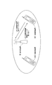
- FIG. 1 is a conceptual diagram of a communication system according to the first embodiment of the present invention.
- base station apparatus B communicates with mobile station apparatuses A11 and A12.
- the mobile station apparatus A1 transmits a mobile station CC capability message to the base station apparatus B.
- the base station apparatus B allocates radio resources to the mobile station apparatus A11 based on the mobile station CC capability message received from the mobile station apparatus A11.
- communication from the mobile station device A11 or A12 to the base station device B is referred to as uplink communication
- communication from the base station device B to the mobile station device A11 or A12 is referred to as downlink communication.
- each of the mobile station devices A11 and A12 is referred to as a mobile station device A1.
- the mobile station device A1 and the base station device B perform communication using CA technology.
- the mobile station apparatus A1 simultaneously receives signals using a plurality of downlink continuous or non-continuous CCs transmitted from the base station apparatus B, and has a pseudo-wide frequency bandwidth (for example, in five CCs). (100 MHz bandwidth) is a technology for forming a carrier signal and realizing a high downlink data transmission rate.
- the base station apparatus B simultaneously receives a plurality of uplink continuous or non-continuous CC signals transmitted from the mobile station apparatus A1, and has a pseudo-wide frequency bandwidth (for example, two CC (40 MHz bandwidth) carrier signal is formed, and a high uplink data transmission rate is realized.
- FIG. 2 is an explanatory diagram of frequency band numbers according to this embodiment (partially extracted from Table 5.5-1. E-UTRA operating bands of 3GPP TS 36.101). This figure shows the relationship between the frequency band number, the upstream frequency band, the downstream frequency band, and the transmission mode.
- the first line corresponds to the frequency band of frequency band number “1” (see frequency band 1 in FIG. 39)
- the uplink frequency band (see band 11 in FIG. 39) is “1920 MHz to 1980 MHz” (band is 60 MHz)
- the downstream frequency band (see band 12 in FIG. 39) is “2110 MHz to 2170 MHz” (band is 60 MHz)
- the transmission mode is “FDD”. Note that it is predicted that the frequency band number (from No. 41) corresponding to the LTE-A system will be added to the related specifications by adding the frequency band corresponding to IMT-Advanced. *
- FIG. 3 is a schematic view showing an example of frequency operation priority scenario information (the scenario in FIG. 3 is referred to as scenario group 1).
- FIG. 4 is a schematic diagram showing another example of frequency operation priority scenario information (the scenario in FIG. 4 is referred to as scenario group 2).
- the scenario information is information indicating a predetermined CC combination.
- scenario information includes a scenario number (Scenario no .; scenario identification information), a deployment scenario, a frequency bandwidth (Transmission BWs of LTE-A carriers), CC information ( No. of LTE-A component carriers, frequency band information (Bands for LTE-A carriers), and transmission modes (Duplex modes) are associated with each other.
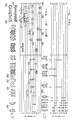
- FIG. 5 is a schematic diagram illustrating an example of frequency allocation indicated by the scenario information.
- FIG. 5 shows the frequencies indicated by the scenario information (S1 to S12) of scenario numbers “1” to “12” in FIG. 3 and the scenario (S13 to S22) information of scenario numbers “13” to “22” in FIG.
- the horizontal axis indicates the frequency.
- the vertical axis is divided into two parts, and shows frequency band scenario groups 1 (upper figure; S1 to S12) and 2 (lower figure; S13 to S22), respectively.
- Each scenario group diagram shows a frequency band (upper diagram) and a CC (lower diagram).
- the hatched block in the lower right diagonal line indicates the band (frequency band or CC) used in the uplink UL (Up link), which is the band of the FDD mode.
- a block hatched with a lower left diagonal line indicates a band used in the downlink DL (Down link) in the FDD mode.
- a block hatched with crossed diagonal lines indicates a TDD mode band and a downlink / uplink shared (DL / UP) band (frequency band or CC).
- the number attached to the top indicates the frequency band number (see FIG. 2), and the number attached to the bottom indicates the frequency.
- the block denoted by reference numeral 101 indicates that it is an uplink frequency band of frequency band number “3”, and the frequency band is “1710-1785” MHz (F UL — low ⁇ F in FIG. 2).
- UL_high indicates a block denoted by reference numeral 102
- a block denoted by reference numeral 102 indicates a downlink frequency band having a frequency band number “3”, and the frequency band is “ 1805 to 1880 ” MHz (F DL_low ⁇ F DL_high in FIG. 2). Indicates that there is.
- the block denoted by reference numeral 103 indicates that the frequency band is “1880-1920” MHz, which is a frequency band that is shared by the TDD mode of the frequency band number “39”. Show.
- the block denoted by reference numeral 104 indicates an 800 MHz UHF (Ultra High Frequency) band not described in the example of FIG. 2, and may be used as an LTE-A frequency band in the future. “UHF” is attached as the scenario number of the examination.
- UHF Ultra High Frequency
- a number attached to the upper part or the lower part indicates a bandwidth (CC frequency bandwidth).
- CC frequency bandwidth For example, in the scenario S1 of the scenario group 1, the frequency band “22” (3.5 GHz band, which is assigned to the TDD mode as the frequency band “41”) assigned with reference numerals 105 and 106 is assigned. Show.
- This is a combination of CCs in a case where two consecutive CCs (20 ⁇ 2 40 MHz; a block denoted by reference numeral 111) are selected in the upstream band (3410-3500 MHz).
- the scenario of S1 is case 1 in FIG.
- the CA technology communication using the frequency band “22” (3.5 GHz band) is performed in the FDD mode, and four non-continuous in the downstream band (3510-3600 MHz).
- the scenario of S4 is case 2 (Intra CA case) in FIG.
- the CA technology is communicated using the frequency band numbers “1”, “3”, and “7” in the FDD mode.
- the scenario of S7 is case 3 (Inter CA case) in FIG.
- CA technology communication is performed using the frequency bands of frequency band numbers “7” and “22” in the FDD mode.
- This is a combination of CCs when an uplink bandwidth of 20 MHz is selected.
- the scenario of S12 is a mixed case of an Inter CA case and an Intra CA case.
- the frequency band “41” (3.5 GHz band, this frequency band is also assigned to the FDD mode as the frequency band “22”) assigned with reference numeral 107 is assigned. .
- the mobile station apparatus A1 and the base station apparatus B perform communication using the selected CC.
- each mobile station apparatus A1 may include transmission / reception apparatuses having different configurations, and CCs that can be handled by the CA technology are different.
- a plurality of configuration examples (transmission / reception devices a1 to a3) of the transmission / reception device included in the mobile station device A1 will be described.
- FIG. 6 is a schematic block diagram illustrating a configuration of the transmission / reception device a1 according to the present embodiment.
- a transmission / reception device a1 includes a transmission / reception shared antenna a101, an antenna duplexer (DUP) a102, a radio reception unit (RF_Rx) a11, a quadrature demodulator (IQ_DM) a12, a baseband demodulation unit (BB_DM) a13, a baseband modulation.
- the antenna duplexer a102 outputs a signal received from the base station apparatus B via the transmission / reception shared antenna a101 to the radio reception unit a11.
- the antenna duplexer a102 transmits the signal input from the radio transmission unit a16 to the base station apparatus B via the transmission / reception shared antenna a101.
- the radio reception unit a11 includes an LNA (Low Noise Amplifier) a111 and an RF reception band limiting filter (Rx_BPF: Rx Band Band Pass Filter) a112.
- the LNA a111 amplifies the signal input from the antenna duplexer a102 and outputs the amplified signal to the RF reception band limiting filter a112.
- the RF reception band limiting filter a112 extracts a reception band signal from the signal input from the antenna duplexer a102 and outputs the signal to the quadrature demodulator a12.
- the quadrature demodulator a12 includes an amplifier (AMP) a121, a local oscillator a122, a phase shifter a123, multipliers a124 and a126, and LPFs (Low Pass Filters) a125 and a127.
- the amplifier a121 amplifies the signal input from the RF reception band limiting filter a112 and outputs the amplified signal to the multipliers a124 and a126.
- the local oscillator a122 generates a sine wave and outputs it to the phase shifter a123.
- the phase shifter a123 outputs the sine wave input from the local oscillator a122 to the multiplier a124.
- the phase shifter a123 generates a cosine wave obtained by shifting the phase of the sine wave input from the local oscillator a122 by 90 degrees and outputs the generated cosine wave to the multiplier a126.
- the multiplier a124 multiplies the signal input from the amplifier a121 by the sine wave input from the phase shifter a123, thereby extracting the in-phase component of the signal and downconverting the signal.
- the multiplier a124 outputs a signal obtained by multiplying the sine wave to the LPF a125.
- the LPF a125 extracts a low frequency component of the signal input from the multiplier a124.
- the LPF a125 outputs the in-phase component of the extracted signal to the baseband demodulation unit a13.
- the multiplier a126 multiplies the signal input from the amplifier a121 by the cosine wave input from the phase shifter a123, thereby extracting a quadrature component of the signal and downconverting the signal.
- the multiplier a126 outputs a signal obtained by multiplying the cosine wave to the LPF a127.
- the LPF a127 extracts a low frequency component of the signal input from the multiplier a126.
- the LPF a127 outputs the in-phase component of the extracted signal to the baseband demodulation unit a13.
- the baseband demodulation unit includes an AD conversion unit (ADC: “Analog” to “Digital” Converter) a131 and a132, a reception digital filter (Rx_DF: “Rx Digital” Filter) a133, a CP (Cyclic Prefix) deletion unit a133, and S / P (serial / parallel).
- a conversion unit a135, an FFT (Fast Fourier Transform) unit a136, a demapping unit a137-1 to a137-s, and a P / S (parallel / serial) conversion unit a138 are configured.
- the AD conversion units a131 and a132 convert the signals (analog signals) input from the LPFs a125 and a127 into digital signals, respectively, and output the digital signals to the reception digital filter a133.
- the reception digital filter a133 extracts a reception band signal from the signals input from the AD conversion units a131 and a132, and outputs the extracted signal to the CP deletion unit a133.
- the CP deletion unit a133 removes the CP from the signal input from the reception digital filter a133 and outputs the CP to the S / P conversion unit a135.
- the S / P conversion unit a135 performs serial-parallel conversion on the signal input from the CP deletion unit a133 and outputs the signal to the FFT unit a136.
- the FFT unit a136 Fourier-transforms the signal input from the S / P conversion unit a135 from the time domain to the frequency domain, and outputs the result to the demapping units a137-1 to a137-s.
- the demapping units a137-1 to a137-s demap the frequency domain signal input from the FFT unit a136 and output the demapped signal to the P / S conversion unit a138.
- the P / S conversion unit a138 performs parallel-serial conversion on the signals input from the demapping units a137-1 to a137-s, and obtains and outputs received data.
- the baseband modulation unit a14 includes an S / P (serial / parallel) conversion unit a141, mapping units a142-1 to a142-t, an IFFT (Inverse Fast Fourier Transform) unit a143, and a P / S (parallel / serial).
- the S / P converter a141 performs serial-parallel conversion on the input transmission data, and outputs it to the mapping units a142-1 to a142-t.
- mapping units a142-1 to a142-t map the signal input from the S / P conversion unit a141 and output it to the IFFT unit a143.
- IFFT section a143 performs inverse Fourier transform on the signals input from mapping sections a142-1 to a142-t from the frequency domain to the time domain, and outputs the result to P / S conversion section a144.
- the P / S conversion unit a144 performs parallel-serial conversion on the time domain signal input from the IFFT unit a143 and outputs the signal to the CP insertion unit a145.
- the CP insertion unit a145 performs parallel-serial conversion on the signal input from the P / S conversion unit a144 and outputs the signal to the transmission digital filter a146.
- the transmission digital filter a146 extracts a signal in the transmission band from the signal input from the CP insertion unit a145.
- the transmission digital filter a146 outputs the in-phase component and the quadrature component of the extracted signal to the DA conversion units a147 and a148, respectively.
- the DA converters a147 and a148 each convert the signal (digital signal) input from the transmission digital filter a146 into an analog signal and output the analog signal to the quadrature modulator a15.
- the quadrature modulator a15 includes LPFs 151 and a152, a local oscillator a153, a phase shifter a154, multipliers a155 and a156, and an amplifier (AMP) a157.
- the LPFs 151 and a152 extract the low frequency components of the signals input from the DA converters a147 and a148, respectively.
- the local oscillator a153 generates a sine wave and outputs it to the phase shifter a154.
- the phase shifter a154 outputs the input sine wave from the local oscillator a153 to the multiplier a155.
- the phase shifter a154 generates a cosine wave in which the phase of the sine wave input from the local oscillator a153 is shifted by 90 degrees and outputs the generated cosine wave to the multiplier a156.
- Multiplier a155 multiplies the signal input from LPFa151 by the sine wave input from phase shifter a154, thereby generating an in-phase component wave and upconverting the signal.
- the multiplier a155 outputs a signal obtained by multiplying the sine wave to the amplifier a157.
- the multiplier a156 multiplies the signal input from the LPF a152 by the cosine wave input from the phase shifter a154, thereby generating a quadrature component wave and upconverting the signal.
- the multiplier a156 outputs a signal obtained by multiplying the cosine wave to the amplifier a157.
- the amplifier a157 amplifies the signals input from the multipliers a155 and a156 and outputs the amplified signals to the wireless transmission unit a16.
- the wireless transmission unit a16 includes an RF transmission band limiting filter (Tx_BPF) a161 and a PA (Power Amplifier) a162.
- the RF transmission band limiting filter a161 extracts a transmission band signal from the signal input from the amplifier a157 and outputs the extracted signal to the PA a162.
- the PA a162 amplifies the signal input from the RF transmission band filter a161 and outputs the amplified signal to the antenna duplexer a102.
- the transmission / reception device a1 transmits a signal using, for example, an uplink CC having a frequency bandwidth of 20 MHz. 6 generates the CC of the uplink OFDM signal.
- the SC-FDMA Single-Carrier-Frequency-Division
- the SC-FDMA Single-Carrier-Frequency-Division
- the SC-FDMA Single-Carrier-Frequency-Division
- the SC-FDMA Single-Carrier-Frequency-Division
- the present invention is not limited to this, and may be applied to other transmission / reception apparatuses such as a superheterodyne system.
- the present invention can be applied by correcting the correspondence between the orthogonal modulation / demodulation units a12 and a15.
- FIG. 7 is a schematic block diagram showing a simplified configuration of the transmission / reception device a1 according to the present embodiment.
- This diagram is a simplified configuration of the transmission / reception device a1 in FIG.
- the transmission / reception device a1 includes a transmission / reception shared antenna a101, an antenna duplexer (DUP) a102, a radio reception unit (RF_Rx) a11, a quadrature demodulator (IQ_DM) a12, a baseband demodulation unit (BB_DM) a13, and a baseband modulation unit (BB_MD). a14, a quadrature modulator (IQ_MD) a15, and a wireless transmission unit (RF_Tx) a16.
- DUP antenna duplexer
- RF_Rx radio reception unit
- IQ_DM quadrature demodulator
- BB_DM baseband demodulation unit
- BB_MD baseband modulation unit
- the transmission / reception device a1 depends on one downlink frequency band (mainly the antenna duplexer a102 and the RF reception band limiting filter a112) determined by the RF frequency characteristics of the radio reception unit (RF_Rx) a11 and the quadrature demodulator (IQ_DM) a12. ), The frequency bandwidth of one downlink CC or a plurality of consecutive CCs determined mainly by the baseband frequency characteristics of the quadrature demodulator (IQ_DM) a12 and the baseband demodulator (BB_DM) a13 (mainly the reception digital filter a CC signal of the base station apparatus B is received.
- IQ_DM quadrature demodulator
- BB_DM baseband demodulator
- the CC signal is transmitted to the base station apparatus B using In the case of the CC combination of case 1 in FIG.
- the transmitting / receiving apparatus a1 has, for example, a baseband frequency bandwidth of 60 MHz corresponding to the center frequency f1_R2 in the downstream band 12 of the frequency band 1 (2 GHz) (IQ_DM) a12 And a baseband demodulator (BB_DM) a13.
- FIG. 8 is a schematic block diagram illustrating a simplified configuration of the transmission / reception device a2 according to the present embodiment.
- DUP antenna duplexer
- RF_Rx radio reception unit
- IQ_DMl L orthogonal demodulator
- BB_DMl L baseband demodulation units
- K baseband modulation units BB_MDl
- IQ_MD1 a25-k
- RF_Tx radio transmission unit
- each of the quadrature demodulator a22-l and each of the baseband demodulation unit a23-l processes a signal received by one or a plurality of continuous downlink CCs associated therewith.
- each of the baseband modulation units a24-k and each of the quadrature modulators a25-k processes a signal to be transmitted using one or more consecutive uplink CCs associated therewith.
- a signal is received by L or less continuous CCs in a single frequency band, and is transmitted by K or less uplink CCs that are continuous or discontinuous. Can do.
- the L orthogonal demodulators a22-l and the baseband demodulator a23-l are provided, it is possible to cope with asynchronous transmission in the downlink CC.
- the baseband frequency bandwidths that can be processed for the L orthogonal demodulator a22-l and the baseband demodulator a23-l are different, the total number of continuous or discontinuous downlink CCs that can be handled, The total number of downlink CCs for transmission and the maximum frequency bandwidth of the combination of consecutive CCs with an OFDM subcarrier bandwidth of 15 kHz also change, resulting in various combinations. The same applies to the uplink.
- the transmitting / receiving apparatus a2 has two baseband frequency bandwidths of 20 MHz corresponding to the center frequencies f1_R1 and f1_R3 in the downstream band 12 of the frequency band 1 (2 GHz), for example.
- An orthogonal demodulator a22-1 and 2 and two baseband demodulation units a23-1 and a23-1 and 2 are provided.
- the transmitting / receiving apparatus a2 includes, for example, two orthogonal modulators a25-1 and a25-2 having a baseband frequency bandwidth of 20 MHz corresponding to the center frequencies f1_T1 and f1_T3 in the upstream band 11 of the frequency band 1 (2 GHz).
- Two baseband modulation units a24-1, 2 are provided.
- the transmission / reception device a2 has a baseband frequency band of 20 MHz corresponding to the center frequencies f1_R1, f1_R2, and f1_R3 in the downstream band 12 of the frequency band 1 (2 GHz), for example.
- Three orthogonal demodulators a22-1, 2, 3 having a width and three baseband demodulation units a23-1, 2, 3 are provided.
- the transmitting / receiving apparatus a2 includes, for example, two quadrature modulators a25-1 and a25-2 having a baseband frequency bandwidth of 20 MHz corresponding to the center frequencies f1_T1 and f1_T2 in the upstream band 11 of the frequency band 1 (2 GHz).
- Two baseband modulation units a24-1, 2 are provided.
- the capability of the transmission / reception apparatus to support the CC combination is referred to as mobile station CC capability.
- the mobile station CC capability of the transmission / reception device a2 is compatible with information indicating a frequency band that can be transmitted (a signal can be transmitted or received) and the frequency bandwidth of each CC in the downstream band (
- information indicating downlink CC frequency bandwidth information indicating the number of consecutive CCs (referred to as downlink consecutive CCs) having each downlink CC frequency bandwidth, and non-contiguous CCs having each downlink CC frequency bandwidth
- Information indicating the number of downlink discontinuous CCs) information indicating the frequency bandwidth of each CC in the uplink band (hereinafter referred to as uplink CC frequency bandwidth), and continuous CCs having each uplink CC frequency bandwidth
- Information indicating the number of uplink continuous CCs indicating the number of non-contiguous CCs having uplink CC frequency bandwidth in each uplink band (referred to as uplink discontinuous CCs) It can be expressed by the information (see FIG.
- the mobile station CC capability of the transmission / reception device a2 is that the frequency band of the downlink CC is the same as the frequency band of the uplink CC. It can be represented by information indicating the frequency bandwidth and information indicating the number of non-contiguous CCs having the uplink CC frequency bandwidth in the downlink band. Note that the FDD or TDD mode can be identified by the frequency band number (see FIG. 2). Therefore, the FDD or TDD mode identification information may not be directly included in the mobile station CC capability, but may be included in the mobile station CC capability.
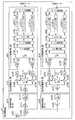
- FIG. 9 is a schematic block diagram showing a simplified configuration of the transmission / reception device a3 according to the present embodiment.
- IQ_DMil orthogonal Demodulator
- BB_DMil baseband demodulation unit
- BB_MDjk baseband modulation unit
- BB_MDjk baseband modulation unit
- antenna duplexer a302-i radio receiver a31-i, quadrature demodulator a32-il, baseband demodulator a33-il, baseband modulator a34-jk, quadrature modulator a35-jk, and radio transmission
- the configuration and functions of the unit a36-j are the antenna duplexer a202, the radio receiving unit a21, the quadrature demodulator a22-l, the baseband demodulator a23-l, the baseband modulator a24-k, and the quadrature unit, respectively. Since it is the same as the modulator a25-k, the description is omitted.
- the set of the quadrature demodulator a32-il and the baseband demodulator a33-il processes the OFDM baseband signal received in the i-th frequency band and the l (lowercase L) downlink CC (each set).
- the set of the baseband modulation unit a34-jk and the quadrature modulator a35-jk processes the OFDM baseband signal received in the i-th frequency band and the k-th uplink CC (each set is a BB modulation branch ik).
- K is called a BB modulation branch number; an element carrier transmission processing unit).
- the set of the radio reception unit a31-i and the BB demodulation branches i1 to iL processes OFDM radio reception signals received in the i-th frequency band (each set is referred to as an RF reception branch i, and i is an RF reception branch). Called number; frequency band reception processing unit).
- a set of the radio transmission unit a36-j and the BB modulation branches j1 to jK processes an OFDM radio transmission signal transmitted in the jth frequency band (each set is referred to as an RF transmission branch j, and j is an RF transmission branch). Called number; frequency band transmission processing unit).
- the transmission / reception device a3 When transmitting / receiving a signal in the same frequency band, the transmission / reception device a3 includes a plurality of RF reception branches i and RF transmission branches j, so that downlink and uplink MIMO schemes, cooperative communication CoMP scheme between base station devices, uplink transmission diversity are provided. It can correspond to the method. Further, when receiving signals of different frequency bands, the transmission / reception device a3 includes a plurality of RF reception branches i and RF transmission branches j, thereby supporting the above method in a plurality of frequency bands as shown in FIG. Can do.
- FIG. 9 shows the case where the number of RF reception branches and the number of RF transmission branches are the same number (I). However, the present invention is not limited to this, and the number of RF reception branches and the RF transmission branches are the same. The number of may vary.
- FIG. 9 shows the case where the number of BB demodulation branches in each RF reception branch is the same number (L). However, the present invention is not limited to this, and the BB demodulation branch in each RF reception branch. The number of may vary. Similarly, the number of BB modulation branches in each RF transmission branch may be different.
- FIG. 9 shows a case where one antenna corresponds to one RF transmission / reception branch.
- FIG. 9 shows a case where one quadrature demodulator (IQ_DM) and one baseband demodulator (BB_DM) correspond, but the present invention is not limited to this, and the frequency of the quadrature demodulator (IQ_DM) is shown.
- one orthogonal demodulator (IQ_DM) may be connected to a plurality of baseband demodulation units (BB_DM) to form one BB demodulation branch.
- the transmission / reception device a3 includes, for example, the RF reception branch 1 corresponding to the center frequency f2_R1 in the downstream band 22 of the frequency band 2 (3 GHz) and the frequency band 1 (2 GHz).
- RF receiving branch 2 corresponding to the center frequency f1_R1 in the downstream band 12.
- the transmission / reception device a3 includes, for example, the RF transmission branch 1 corresponding to the center frequency f1_T1 in the upstream band 11 of the frequency band 1 (2 GHz). Further, in the case of corresponding to the CC combination of case 1 in FIG.
- the transmission / reception device a3 for example, downlinks in frequency band 1 (2 GHz)
- the transmission / reception device a3 includes, for example, two RF transmission branches 1 and 2 corresponding to the upstream band 11 of the frequency band 1 (2 GHz).
- the radio parameters of the mobile station apparatus include Supported Band EUTRA (Supported Band of EUTRA) indicating a frequency band number, Supported DLCC BW List (Supported Downlink Component Carrier Bandwidth List) indicating a frequency bandwidth of a downlink CC.
- Supported Band EUTRA Serial Band of EUTRA
- Supported DLCC BW List Serial Downlink Component Carrier Bandwidth List
- Supported DLCOCCList (Supported Downlink Contiguous Component Carrier List; continuous element carrier number information) indicating the number of downlink CCs continuous in the frequency band
- Supported DLNCCCList (Supported Downlink Non-Contiguous Component Carrier List) indicating the number of downlink CCs not continuous in the frequency band
- Non-continuous element carrier number information Supported DLCC MIMO List (Supported Downlink Component Carrier MIMO List; MIM) indicating the number of downlink CC MIMO streams Stream number information
- Supported ULCCCBWList (Supported Uplink Component Carrier Bandwidth List; frequency bandwidth information) indicating the frequency bandwidth of the uplink CC
- Supported ULCOCCList (Supported Uplink Contiguous Component Carrier List) indicating the number of uplink CCs continuous in the frequency band
- Carrier number information Supported ULNCCCList (Supported Uplink Non-Contiguous Component Carrier List information) indicating
- the radio parameter “SupportedBandEUTRA” is information indicating the frequency band number of FIG. This radio parameter is a sequence of frequency band numbers of frequency bands that can be supported by the transmission / reception apparatus a3 of FIG.
- the radio parameter “SupportedDLCCBWList” is information indicating the frequency bandwidth number of the downlink CC.
- This radio parameter is a list indicating the frequency bandwidths of consecutive CCs included in the downlink band that can be supported by the transmission / reception apparatus a3 in FIG. 9, that is, a sequence of downlink consecutive CC frequency bandwidth numbers, and the frequency characteristics of the BB demodulation branch and Relatedly, it represents the mobile station CC capability.
- FIG. 11 is an explanatory diagram of CC frequency bandwidth numbers according to the present embodiment. This figure shows the relationship between CC frequency bandwidth numbers and CC frequency bandwidth.
- CC frequency bandwidth numbers 1 to 6 correspond to CC frequency bandwidths 1.4 to 20 MHz
- CC frequency bandwidth number “4” has a CC frequency bandwidth of “10” MHz.
- the CC frequency bandwidth number 7 and later are reserved, and may correspond to other CC frequency bandwidths or combined maximum frequency bandwidths of continuous CCs.
- the ascending order of the CC frequency bandwidth number is the ascending order of the size of the CC frequency bandwidth, but may be another correspondence relationship.
- the radio parameter SupportedDLCOCCList is information indicating the number of downlink continuous CCs.
- This radio parameter is a list indicating the number of consecutive downlink CCs included in the downlink band that can be supported by the transmission / reception apparatus a3 of FIG. Represents CC capability.
- the radio parameter SupportedDLNCCCList is information indicating the number of downlink non-contiguous CCs. This radio parameter is a list indicating the number of non-consecutive downlink CCs included in the downlink band that can be supported by the transmission / reception device a3 in FIG. Represents CC capability.
- the radio parameter Supported DLCC MIMO List is information indicating the number of downlink CC MIMO streams. This radio parameter is a sequence of the number of MIMO streams for each CC for the downlink CC included in the downlink band that can be supported by the transmission / reception apparatus a3 in FIG. .
- the radio parameter SupportedULCCBWList is information indicating the frequency bandwidth number of the uplink CC.
- This radio parameter is a list indicating the frequency bandwidths of consecutive CCs included in the uplink band that can be supported by the transmission / reception device a3 in FIG. 9, that is, a sequence of uplink CC frequency bandwidth numbers, and the frequency characteristics of the BB modulation branch.
- it represents the mobile station CC capability.
- the radio parameter Supported ULCOCCList is information indicating the number of uplink continuous CCs. This radio parameter is a list indicating the number of consecutive uplink CCs included in the uplink band that can be supported by the reception device a3 of FIG. Represents CC capability.
- the radio parameter SupportedULNCCCList is information indicating the number of uplink non-consecutive CCs. This radio parameter is a list indicating the number of non-consecutive uplink CCs included in the uplink band that can be supported by the transmission / reception device a3 in FIG. Represents CC capability.
- the radio parameter Supported ULCC MIMO List is information indicating the number of uplink CC MIMO streams. This radio parameter is a sequence of the number of MIMO streams for each CC with respect to the uplink CC included in the uplink band that can be supported by the transmission / reception device a3 in FIG. 9, and represents the mobile station CC capability in relation to the number of RF transmission branches. .
- FIG. 10 is a schematic diagram illustrating an example of a relationship between a scenario and a wireless parameter according to the present embodiment.
- FIG. 10 is a diagram illustrating radio parameters of the transmission / reception device a3 corresponding to the scenarios S4, S7, and S10 of FIG. ⁇ Wireless parameters of transmission / reception apparatus a3 corresponding to S4 scenario>
- the radio parameter of the transmission / reception device a3 that can support the scenario of S4 since it corresponds to the frequency band number “22” (see FIG.
- SupportedBandEUTRA [22]
- the CC frequency bandwidth of the downlink CC is “20” MHz (FIG. 11)
- the supported DLCCBWList [6] according to FIG. 11, and the number of downlink continuous CCs “2” (see FIG. 5).
- SupportedDLNCCCList [2].
- the result of multiplication of SupportedDLCOCCList and SupportedDLNCCCList is “4” (2 ⁇ 2).
- the supported ULCCBWList [6] according to FIG. (See FIG. 5).
- Supported ULCOCCList [1] for correspondence
- Supported ULNCCCList [2] for correspondence with the number of uplink non-continuous CCs “2” (see FIG. 5).
- the result of multiplication of SupportedULCOCCList and SupportedDLNCCCList is “2” (1 ⁇ 2).
- SupportedDLCCBWList [4, 4, 6] Since it corresponds to the number of downlink continuous CCs “1”, “1”, “1” (see FIG.
- SupportedDLCOCCList [1,1,1], and downlink non-continuous CCs of each frequency band.
- the result of multiplication of the supported DLCOCCList and the supported DLNCCCList is “1 (1 ⁇ 1), 1 (1 ⁇ 1), 1 (1 ⁇ 1)”.
- FIG. [4,4,6]
- supported ULCOCCList [1,1,1] because it corresponds to the number of consecutive uplink CCs “1”, “1”, “1” (see FIG. 5) of each frequency band.
- SupportedULNCCCList [1, 1, 1].
- the SupportedDLNCCCList [1,1,1]. Also, the result of multiplication of the supported DLCOCCList and the supported DLNCCCList (multiplying the same components) is “2 (2 ⁇ 1), 1 (1 ⁇ 1), 2 (2 ⁇ 1)”.
- SupportedULNCCCList [1, 1, 1].
- the transmitting / receiving apparatus a3 allocates one MIMO stream to one 10 MHz uplink CC in the frequency band “34”, and, for example, the frequency to two 20 MHz uplink CCs in the frequency band “40”. Indicates that four or two MIMO streams are allocated in ascending order.
- FIG. 12 is a schematic block diagram showing the configuration of the mobile station apparatus A1 according to this embodiment.
- a mobile station apparatus A1 includes a transmission / reception apparatus A101, a control unit A102, an allocation information storage unit A103, a mobile station CC capability information storage unit A104, an ASN (Abstract Syntax Notation) encoding unit A105, and an RRC (Radio Resource Control).
- the message generation unit A106 is included.
- the transmission / reception device A101 is the transmission / reception device a1, a2, or a3.
- the control unit A102 controls each unit of the mobile station device A1. For example, the control unit A102 receives the radio resource information allocated from the base station apparatus B as control data, and stores the received radio resource information in the allocation information storage unit A103. At the time of user data transmission / reception, the control unit A102 reads radio resource information from the allocation information storage unit A103 and controls user data transmission / reception.
- the mobile station CC capability information storage unit A104 stores, in a memory, mobile station CC capability information (for example, radio parameter information, details will be described later) indicating CCs that the device can handle.
- the mobile station CC capability information information according to the mobile station device configuration is written in the mobile station CC capability information storage unit A104 at the time of factory shipment, but may be updated thereafter. Also, the control unit A102 outputs the mobile station CC capability information stored in the mobile station CC capability information storage unit A104 to the ASN encoding unit A105.
- the mobile station CC capability information includes radio parameters of the mobile station device. Details of the mobile station CC capability information will be described later together with the RRC message generation process.
- the ASN encoding unit A105 converts the mobile station CC capability information input from the control unit A102 into an abstract syntax notation 1 (ASN.1) format, encodes the encoded information, and generates an RRC message generation unit Output to A106. That is, the ASN encoding unit A105 generates mobile station CC capability information including information indicating a CC that can be used for communication with the base station apparatus B1. The details of the process performed by the ASN encoding unit A105 will be described later together with the RRC message generation process.
- ASN.1 abstract syntax notation 1
- the RRC message generator A106 generates an LTE-A mobile station CC capability message (UE-EUTRA-Capability), which is mobile station CC capability information including information input from the ASN encoder A105, and is included in the control data As a part of the uplink RRC message, the message is output to the transmission / reception apparatus A101.
- UE-EUTRA-Capability LTE-A mobile station CC capability message
- the details of the process performed by the RRC message generation unit A106 will be described later together with the RRC message generation process.
- the transmission / reception device A101 processes the RRC message input from the RRC message generation unit A106 using one or a plurality of RF transmission branches and transmits the processed RRC message to the base station device B.
- the control unit A102, the allocation information storage unit A103, the mobile station CC capability information storage unit A104, the ASN encoding unit A105, and the RRC message generation unit A106 may be included in the integrated circuit chip.
- a configuration in which a part or all of the transmission / reception device A101 is included in the integrated circuit chip may be used, and the present invention is not limited thereto.
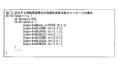
- FIG. 13 is a schematic diagram illustrating an example of a structure of a mobile station CC capability message (UE-CC-Capability) according to the present embodiment.
- the parameter maxCCBWs is the number of the maximum CC frequency bandwidth.
- maxCCBWs is the maximum CC frequency bandwidth number “6” in the example of FIG. 11.
- the parameter maxCOCCs is the maximum number of consecutive CCs.
- maxCOCCs is “6” when each scenario in FIG. 5 and a combination of two scenarios are considered.
- the parameter maxNCCCs is the maximum number of non-contiguous CCs. For example, maxNCCCs is “6” when each scenario in FIG. 5 and a combination of two scenarios are considered.
- the parameter maxMIMOs is the maximum number of MIMO streams. For example, max MIMOs is “8” when a maximum of eight antennas are considered.
- the parameter maxBands is the maximum number of frequency bands. For example, maxBands is “64” when the frequency band number “41” in FIG. 2 is considered.
- the parameter maxUEBands is the maximum number of frequency bands that the mobile station apparatus can handle. For example, maxUEBands is “6” when considering the complexity, power consumption, cost, productivity, international roaming, and the like of the mobile station apparatus.
- the structure of the LTE-A mobile station CC capability message includes the structure of radio parameters (UE-Parameters) of the mobile station apparatus and other parameters.
- the structure of the radio parameters of the mobile station apparatus include SupportedBandEUTRA, SupportedDLCCBWList, SupportedDLCOCCList, SupportedDLNCCCList, SupportedDLCCMIMOList, SupportedULCCBWList, SupportedULCOCCList, SupportedULNCCCList, and nine wireless parameters SupportedULCCMIMOList.
- Other parameter structures are parameters of other specifications described in 3GPP standard TS36.331 (Radio Resource Control), and are omitted.
- “SupportedBandEUTRA” includes a bandEUTRA indicating the maximum frequency band “64” frequency band numbers, and any one of “1” to “64” is assigned to bandEUTRA.
- Supported DLCCBWList includes DLCCBW indicating the number of CC frequency bandwidths of “6” at the maximum maxCCBWs, and any integer of “0” to “6” is substituted for DLCCBW.
- the supported DLCOCCList includes DLCOCC indicating the number of maximum consecutive UEs having “6” number of downlink continuous CCs, and an integer of “0” to “6” is assigned to DLCOCC.
- the supported DLNCCCList includes a DLNCCC indicating the number of maximum discontinuous CCs of max UE Bands “6”, and an integer of “0” to “6” is assigned to the DLNCCC.
- the Supported DLCC MIMO List includes DLCC MIMO indicating the number of MIMO streams of “216” downlink CCs of maximum max UE Bands “6” ⁇ (multiplication) maxCOCCs “6” ⁇ (multiplication) maxNCCCs “6”, and DLCC MIMO is “0”. Any integer of “8” is substituted.
- the supported ULCCBWList includes a ULCCBW indicating the number of CC frequency bandwidths with a maximum maxCCBWs of “6”, and an integer of “0” to “6” is assigned to the ULCCBW.
- the supported ULCOCCList includes ULCOCC indicating the number of maximum continuous UEs with “6” maximum UEUEBands, and any integer of “0” to “6” is substituted for ULCOCC.
- the supported ULNCCCList includes ULNCCC indicating the maximum number of max UE Bands “6” non-contiguous uplink CCs, and an integer of “0” to “6” is assigned to ULNCCC.
- the supported ULCC MIMO list includes ULCC MIMO indicating the number of MIMO streams of “216” uplink CCs of maximum maxUEBands “6” ⁇ (multiplication) maxCOCCs “6” ⁇ (multiplication) maxNCCCs “6”, and ULCC MIMO is “0”. Any integer of “8” is substituted.
- the LTE-A mobile station apparatus A1 substitutes the values of the radio parameters of the LTE-A mobile station apparatus A1 that can correspond to the scenarios S4, S7, and S10, respectively, in the LTE-A mobile station CC capability message structure of FIG. To do.
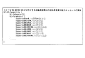
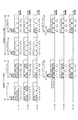
- FIG. 14 is a schematic diagram showing an example of actual (ASN.1 Object Instance) data of the mobile station CC capability message according to the present embodiment.
- wireless parameter since the value of each radio
- the CC of the TDD mode is used, that is, some of the radio parameters are the same for the uplink and the downlink.
- the wireless parameter may be omitted.
- the radio parameters of LTE-A mobile station apparatus A1 that can support the scenario of S10 may be omitted because the radio parameters of SupportedULCCBWList, SupportedULCOCCList, and SupportedULNCCCList are the same as those of downlink.
- the LTE-A mobile station apparatus A1 that can handle the scenarios of S3, S7, and S10, different numbers of MIMO streams can be used for each CC, but it is limited to using the same number of MIMO streams for each frequency band. May be.
- the LTE-A mobile station apparatus A1 that can support the scenario of S10 has the number of MIMO streams “1” in two downlink continuous CCs in the frequency band number “39” and one downlink non-continuous CC in the frequency band number “34”.
- the number of MIMO streams is “2” and the frequency band number “40” corresponds to the number of MIMO streams “4” for two consecutive CCs
- Supported DLCC MIMOList [1, 2, 4].
- the number of MIMO streams is “1” for two upstream continuous CCs in frequency band number “39”, the number of MIMO streams is “1” in one upstream non-continuous CC in frequency band number “34”, and the frequency band number is “40”.
- Supported ULCC MIMO List [1, 1, 2].
- the LTE-A mobile station CC capability message can be shortened.
- the same number of MIMO streams can be used for each frequency band, but the same number of MIMO streams is limited to all frequency bands. Also good.
- the LTE-A mobile station CC capability message can be shortened.
- the number of MIMO streams is set so that the mobile station CC capability information of the mobile station device A1 has a data processing capability related to the downlink and uplink data transmission rates of the mobile station device. Specifically, the number of MIMO streams is set so that the maximum downlink and uplink data transmission rates calculated from the mobile station CC capability information are within the bit size of the data buffer.
- FIG. 15 is a schematic block diagram showing the configuration of the base station device B1 according to the present embodiment.
- base station apparatus B1 is comprised including transmission / reception apparatus B101, control part B102, allocation information storage part B103, RRC message extraction part B106, ASN decoding part B105, and mobile station CC capability information storage part B107.
- the transmission / reception device B101 transmits / receives data to / from the mobile station device A1. Since the transmission / reception device B101 has the same basic configuration and basic functions as the transmission / reception device a3, the description thereof is omitted.
- the RRC message extraction unit B106 extracts the RRC message from the control data of the higher layers 2 and 3 transmitted from the mobile station device by the transmission / reception device B101, and outputs the RRC message to the ASN decoding unit B105.
- the ASN decoding unit B105 decodes the RRC message input from the RRC message extraction unit B106, that is, information encoded in the format of abstract syntax notation 1 (ASN.1).
- the ASN decoding unit B105 extracts entity data from the decoded information based on the structure of the mobile station CC capability message shown in FIG.
- the ASN decoding unit B105 outputs the extracted entity data to the control unit B102 as mobile station CC capability information.
- the control unit B102 controls each unit of the base station device B1.
- the control unit B102 stores the mobile station CC capability information input from the ASN decoding unit B105 in the mobile station CC capability information storage unit B107.
- the control unit B102 determines allocation of uplink and downlink radio resources of the mobile station device A1 based on the mobile station CC capability information stored in the mobile station CC capability information storage unit B107 (referred to as resource allocation determination processing).
- the control unit B102, the allocation information storage unit B103, the RRC message extraction unit B106, and the ASN decoding unit B105 may be included in the integrated circuit chip.
- a configuration in which a part or all of the transmission / reception device B101 is included in the integrated circuit chip may be used, and the present invention is not limited thereto.
- the control unit B102 determines allocation of uplink and downlink radio resources of the mobile station device A1 based on the communication capability of the own device and the mobile station CC capability information. Note that the control unit B102 stores in advance base station device communication capability information indicating the communication capability of the own device. A specific example of the resource allocation determination process is shown below.
- FIG. 16 is a diagram showing another example of entity data of the mobile station CC capability message according to the present embodiment.
- the control unit B102 performs resource allocation determination processing as follows.
- the control unit B102 determines that one 15 MHz (CC frequency bandwidth number “5”) uplink non-continuous CC and one 15 MHz downlink non-continuous CC can be allocated in the frequency band “3”. . Similarly, in the frequency band “1”, the control unit B102 determines that one 15 MHz upstream non-continuous CC and one 15 MHz downstream non-continuous CC can be assigned. In this case, the control unit B102 considers radio propagation conditions, load balance, and the like, for example, in the frequency bands “3” and “1”, the appropriate two 15 MHz uplink discontinuous CCs and the appropriate two 15 MHz A downlink non-continuous CC is assigned.
- the control unit B102 notifies the mobile station apparatus A1 of information such as the assigned CC number and carrier frequency at the time of initial access (for example, random access) from the mobile station apparatus A1.
- the control unit B102 transmits one of the two downlink CCs to which the downlink radio resource of the mobile station apparatus A1, that is, the downlink resource block RB (Resource Block) in which the mobile station apparatus A1 receives the own apparatus data, is allocated.
- the control unit B102 assigns one or two uplink CCs to the uplink radio resource of the mobile station device A1, that is, the uplink resource block RB to which the mobile station device A1 transmits its own device data. Assign within.
- the control unit B102 has “2” as the number of MIMO streams that can be handled by each of the two 5 MHz downlink non-contiguous CCs in the frequency band “8”. In the frequency bands “3” and “1”, it is determined that the number of MIMO streams that can be handled by each of the two 15 MHz downlink non-continuous CCs is “4”. In this case, the control unit B102 considers the radio propagation status, the load balance, and the like, and, for example, the number of MIMO streams “2” for each of two 15 MHz downlink discontinuous CCs in the frequency bands “3” and “1”. ".
- the control unit B102 has “1” as the number of MIMO streams that can correspond to each of the two 5 MHz uplink non-continuous CCs in the frequency band “8”. Yes, in frequency bands “3” and “1”, it is determined that the number of MIMO streams that each of the two 15 MHz uplink non-continuous CCs can handle is “2”. For example, the control unit B102 considers the radio propagation status, load balance, and the like, and sets the number of MIMO streams “1” for each of the two 15 MHz uplink discontinuous CCs in the frequency bands “3” and “1”, for example. assign.
- the allocation information storage unit B103 stores the radio resource allocation information to the mobile station device A1 determined by the control unit B102.
- the control unit B102 generates control data including layer 1, 2, and 3 control data including radio resource allocation information, and transmits the control data to the mobile station apparatus A1 via the transmission / reception apparatus B101.
- the control unit B102 determines that one 15 MHz upstream non-continuous CC and one 15 MHz downstream non-continuous CC can be allocated in the frequency band “1”. In this case, the control unit B102 considers the radio propagation status, load balance, and the like, and, for example, in the frequency band “1”, an appropriate 15 MHz uplink non-continuous CC and an appropriate 15 MHz downlink non-continuous CC. Assign.
- the control unit B102 notifies the mobile station apparatus A1 of information such as the assigned CC number and carrier frequency at the time of initial access (for example, random access) from the mobile station apparatus A1. Also, the control unit B102 allocates downlink radio resources of the mobile station device A1 in the allocated CC.
- the control unit B102 has “2” as the number of MIMO streams that can be handled by each of the two 5 MHz downlink non-contiguous CCs in the frequency band “8”. In the frequency bands “3” and “1”, it is determined that the number of MIMO streams that can be handled by each of the two 15 MHz downlink non-continuous CCs is “4”. In this case, the control unit B102 assigns the number of MIMO streams “2” to two 15 MHz downlink discontinuous CCs in the frequency band “1” in consideration of the radio propagation status, load balance, and the like.
- the control unit B102 has “1” as the number of MIMO streams that can correspond to each of the two 5 MHz uplink non-continuous CCs in the frequency band “8”. Yes, in frequency bands “3” and “1”, it is determined that the number of MIMO streams that each of the two 15 MHz uplink non-continuous CCs can handle is “2”. For example, the control unit B102 assigns the number of MIMO streams “1” to one 15 MHz uplink discontinuous CC in the frequency band “1” in consideration of the radio propagation status, load balance, and the like.
- the allocation information storage unit B103 stores radio resource allocation information to the mobile station device A1 determined by the control unit B102, and the control unit B102 generates control data including the radio resource allocation information, and transmits the mobile station via the transmission / reception device B101. Transmit to device A1.
- the mobile station apparatus A1 is a mobile station apparatus A1 that can cope with the scenarios S5 and S8.
- S1-S22 Not only a scenario but various CC combinations can be represented. That is, the base station apparatus B1 can select CCs corresponding to various LTE-A mobile station CC capability messages of the mobile station apparatus A1.
- FIG. 17 is a schematic diagram illustrating an example of frequency allocation indicated by another scenario information according to the present embodiment.
- FIG. 18 is a diagram showing another example of entity data of the mobile station CC capability message according to the present embodiment.
- the control unit B102 performs resource allocation determination processing as follows.
- the control unit B102 determines that two 5 MHz upstream non-continuous CCs and two 5 MHz downstream non-continuous CCs can be allocated in the frequency band “8”. Further, the control unit B102 determines that one 15 MHz upstream non-continuous CC and two 15 MHz downstream continuous CCs can be allocated in the frequency band “1”. In this case, the control unit B102 considers radio propagation conditions, load balance, and the like. For example, in the frequency band “8”, the appropriate two 5 MHz uplink discontinuous CCs and the appropriate two 5 MHz downlink discontinuous CCs. Assign.
- the control unit B102 assigns an appropriate 15 MHz uplink non-continuous CC and appropriate two 15 MHz downlink continuous CCs.
- the control unit B102 notifies the mobile station apparatus A1 of information such as the assigned CC number and carrier frequency at the time of initial access (for example, random access) from the mobile station apparatus A1.
- the control unit B102 allocates downlink radio resources of the mobile station device A1 in the allocated CC.
- the control unit B102 determines that the number of MIMO streams that can correspond to each of the two 5 MHz downlink non-continuous CCs in the frequency band “8” is “2”.
- the number of MIMO streams that can be handled by each 10 MHz downlink discontinuous CC in the frequency band “3” is “1”, and each of the two 15 MHz downlink discontinuous CCs can be handled in the frequency band “1”. It is determined that the number of MIMO streams is “4”.
- the control unit B102 determines that the number of MIMO streams that can be supported by each 15 MHz uplink non-continuous CC is “2”.
- the control unit B102 considers radio propagation conditions, load balance, and the like, for example, assigns the number of MIMO streams “1” to two 5 MHz uplink discontinuous CCs in the frequency band “8”, and the frequency band “1”.
- the number of MIMO streams “2” is allocated to each 15 MHz upstream non-continuous CC.
- the allocation information storage unit B103 stores radio resource allocation information to the mobile station device A1 determined by the control unit B102, and the control unit B102 generates control data including the radio resource allocation information, and transmits the mobile station via the transmission / reception device B101. Transmit to device A1.
- the mobile station apparatus A1 transmits mobile station element carrier capability information including information indicating the CC that can be used for communication with the base station apparatus B1 to the base station apparatus B1. .
- base station apparatus B1 allocates CC used for communication with respect to mobile station apparatus A1 based on the mobile station element carrier capability information received from mobile station apparatus A1.
- the mobile station apparatus A1 performs communication with the base station apparatus using the CC assigned by the base station apparatus B1 based on the mobile station element carrier capability information.
- wireless resource suitable for communication with mobile station apparatus A1 and base station apparatus B1 can be allocated.
- the control unit B102 of the base station device B compares the mobile station CC capability information from the mobile station device A1 with the base station device communication capability information of the own device, and the communication capability of the own device. Within the range of the mobile station apparatus communication capability, appropriate downlink and uplink radio resource allocation can be performed for the mobile station apparatus A1.
- mobile stations can be combined with various combinations of LTE-A mobile station apparatus configurations corresponding to various LTE-A technical elements as described in (a) to (b) above.
- the base station device B1 By generating the device configuration information and transmitting it to the base station device B1, the base station device B1 performs appropriate performance of the mobile station device A1 that can support various LTE-A technical elements according to the mobile station device configuration information. And appropriate uplink and downlink radio resources can be allocated.
- the LTE-A mobile station CC capability message shown in FIGS. 13 and 14 includes the radio parameter of SupportedBandListEUTRA, but the radio parameter of the power amplifier PA included in each RF transmission branch number is as follows.
- SupportedPAoutList indicating the maximum transmission power level may be included.
- this SupportedPAoutList includes the maximum RF transmission branch number “I” maximum transmission power level number PAout, and the maximum transmission power level number PAout is, for example, an integer of “1” to “2”. It may be substituted.
- PAout “1, 1, 2, 2” means that the maximum transmission power level of the PA of the RF transmission branch numbers 1 and 2 is 23 dBm, the RF transmission branch number 3, The maximum transmission power level of the PA of 4 may represent 20 dBm.
- bandEUTRA included in SupportedBandListEUTRA shows the relationship between the uplink frequency band band, the downlink frequency band band, the frequency band bandwidth, and the transmission mode as shown in FIG. 2, but some continuous uplink frequency band bands. It is also possible to redefine a new and wide upstream frequency band band and downstream frequency band band by combining the downstream frequency band bands.
- the new frequency band number “1” may be combined with the frequency band numbers “1” and “2” of FIG. 2 to correspond to the upstream frequency band band of 1920 MHz to 2170 MHz and the downstream frequency band band of 1850 MHz to 1990 MHz. it can.
- FIG. 9 shows that one RF reception branch includes a plurality of BB demodulation branches and one RF transmission branch includes a plurality of BB modulation branches. If the frequency bandwidth of the transmitter a15 and the quadrature demodulator a12 is wide and the same as the transmission / reception band, one orthogonal modulator and one orthogonal demodulator are used for one radio transmission / reception unit in one RF transmission / reception branch. Also good.
- a configuration including one transmission / reception antenna and one DUP, or a plurality of transmission / reception antennas and a plurality of DUPs, a plurality of separate wireless transmission / reception units, a quadrature modulator and a quadrature demodulator, and a baseband modulator and a baseband demodulator A plurality of RF transmission / reception branches may be used.
- the base station apparatus when the mobile station apparatus transmits mobile station CC capability information including radio parameters to the base station apparatus, the base station apparatus allocates appropriate radio resources to various CC combination mobile station apparatuses. It was shown that you can.
- the mobile station CC capability of the mobile station apparatus not only improves the data transmission rate, but also various LTE-A technical elements as described above, for example, (Co) Cooperative communication between base station apparatuses, (Co) uplink transmission Diversity system, (sa) the frequency allocation situation of each mobile phone service operator, (g) domestic or international roaming, so the data transmission speed of the mobile station device is only the mobile station CC capability of the mobile station device In some cases, the bit size of the data buffer is limited.
- the mobile station apparatus transmits a mobile station CC capability message including mobile station apparatus category information (see FIG. 24) representing the maximum data transmission rate in addition to the radio parameters in the first embodiment to the base station apparatus.
- mobile station apparatus category information (see FIG. 24) representing the maximum data transmission rate in addition to the radio parameters in the first embodiment to the base station apparatus.
- the base station apparatus allocates radio resources used for communication with the mobile station apparatus by the mobile station CC capability message.
- the conceptual diagram of the communication system according to the present embodiment is the same as FIG. 1 of the first embodiment, and a description thereof will be omitted.
- Each of the mobile station devices A11 and A12 according to the present embodiment is referred to as a mobile station device A2.
- the mobile station device A2 includes a transmission / reception device a1 (FIG. 6), a2 (FIG.
- LTE mobile station device category in the prior art (LTE) will be described first, and then a mobile station device category (LTE-A) in the present embodiment (LTE-A). Mobile station device category) will be described.
- FIG. 19 is a schematic diagram of LTE mobile station apparatus category correspondence information according to the second embodiment of the present invention.
- This figure shows that there are five (Category 1-5) LTE mobile station device categories (Category).
- This figure also shows the downlink (DL) and uplink (UL) data transmission rates (related to bit rate, bit size of the data buffer) of the mobile station device, downlink and uplink of the mobile station device, depending on the LTE mobile station device category.
- Modulation Scheme Modulation Scheme
- LTE mobile station apparatus category 1 (Category 1)
- the downlink data transmission rate of the mobile station apparatus is “10 Mbps”
- the uplink data transmission rate is “5 Mbps”
- the downlink modulation scheme is “QPSK, 16QAM or 64QAM”
- the upstream modulation scheme is" QPSK, 16QAM "
- the number of downstream MIMO streams is" 1 ".
- the LTE-A mobile station apparatus adopts the CA technology, the downlink data transmission rate and the number of downlink MIMO streams cannot correspond one-on-one like the LTE mobile station apparatus.
- FIG. 20 is a schematic diagram showing an example of the relationship between the present embodiment according CC frequency bandwidth BW Channel (Channel bandwidth) and a radio resource block number N RB.
- BW Channel Channel bandwidth
- N RB radio resource block number
- FIG. 21 is a schematic diagram illustrating an example of the relationship between the CC frequency bandwidth and the maximum transport block size according to the present embodiment.
- the 3GPP specifications TS36.213 Physical layer procedures
- transport block size; for (TBS Transport block size) the relationship between the transport block size index (TBS Index) and radio resource block number N RB are listed. Therefore, regarding the transport block size, the relationship between the CC frequency bandwidth BW Channel and the transport block size index (TBS Index) can be derived.
- the transport block size index (TBS Index) depends on the MCS index (Modulation and Coding Scheme Index) and the modulation degree (Modulation Order) of adaptive modulation, which are parameters of data modulation, and is “0” to “26”. Is defined.
- FIG. 21 shows the transport block size index when the transport block size is maximum (maximum transport block size; TBS max ), that is, the transport block size when the data transmission rate BR (Bit Rate) is maximum.
- the index is “26”.
- This figure shows the relationship between the CC frequency bandwidth BW Channel and the transport block size for the transport block size index “26”.
- the maximum data transmission rate BR can be calculated from the CC frequency bandwidth BW Channel .
- FIG. 22 is a schematic diagram illustrating an example of a relationship diagram between the number of MIMO streams and the maximum data transmission rate in each scenario according to the present embodiment.
- This figure shows the maximum data transmission rate calculated using the CC frequency bandwidth for each number of MIMO streams in the scenarios S1 to S22. That is, the maximum data transmission rate in this figure is obtained by extracting the maximum data transmission rate from the CC frequency bandwidth of CC in each scenario using FIG. 21, and adding the number of CCs and the number of MIMO streams to the extracted maximum data transmission rate. It is calculated by multiplication.
- the uplink frequency bandwidth is 20 ⁇ 2 MHz.
- two continuous CCs of 20 MHz are regarded as one CC, and there are two CCs, so that the downlink frequency bandwidth is 20 ⁇ 4 MHz.
- the maximum data transmission BR is 75376 kbps.
- FIG. 23 is a conceptual diagram showing an example of the maximum uplink and downlink data transmission rates according to this embodiment.
- all the downlink maximum data transmission rates BR and all the uplink maximum data transmission rates BR in FIG. 22 are ordered.
- 25 different downlink data transmission rates BR (DL BR) and 26 different uplink maximum data transmission rates BR (UL BR) are obtained.
- FIG. 24 is a schematic diagram showing an example of LTE-A mobile station apparatus category information according to the present embodiment. This figure shows the relationship between the category number of LTE-A mobile station equipment category (“6” to “10”; Category 6, 7, 8, 9, 10) and the maximum data transmission rate of uplink and downlink. Show. Further, the maximum data transmission rate in each category is obtained by selecting the maximum data transmission rates of BR11 to BR15 and BR21 to BR25 from the maximum data transmission rates of FIG. FIG. 24 shows that, for example, in the case of LTE-A mobile station category 6 (Category 6), the maximum downlink data transmission rate of the mobile station device is “36672 kbps” and the maximum uplink data transmission rate is “35376 kbps”. . That is, the mobile station device category information represents the maximum data transmission rate.
- LTE-A mobile station equipment category (“6” to “10”; Category 6, 7, 8, 9, 10)
- the maximum data transmission rate in each category is obtained by selecting the maximum data transmission rates of BR11 to BR15
- “10” is selected as the largest category number of the LTE-A mobile station apparatus category. This is because, for the largest LTE-A mobile station device category, the IMT-Advanced requirement is that the maximum uplink data transmission rate is “500 Mbps” and the maximum downlink data transmission rate is “1000 Mbps”. It is. That is, as a numerical value that can satisfy this requirement, the maximum uplink data transmission rate is 603008 kbps and the maximum downlink data transmission rate is 12060616 kbps. In FIG. 24, “6” is selected as the largest category number of the LTE-A mobile station apparatus category.
- the maximum uplink data transmission rate can be dealt with in the scenario where the maximum downlink data transmission rate is minimum (S12) and the scenario where the maximum uplink data transmission rate is minimum (S5, S13 to S22). Is 35376 kbps, and the maximum downlink data transmission rate is 36672 kbps. Further, for the uplink and downlink data transmission rates of other categories, three bears are selected with reference to the ratio between the LTE mobile station device categories and the ratio between the uplink and downlink data transmission rates in FIG. Note that the LTE-A mobile station apparatus category of the present invention is not limited to that shown in FIG. 24.
- the complexity of the LTE-A mobile station apparatus hardware configuration eg, capacity of data buffer memory, RF transmission and reception
- the maximum data transmission rate in FIG. 23 may be selected in consideration of the number of branches, the number of BB modulations and the number of demodulation branches, etc.), power consumption, price, productivity, and the like.
- the LTE mobile station apparatus category definition in FIG. 19 may be changed and redefined to include part or all of the LTE-A mobile station apparatus category.
- FIG. 25 is a schematic block diagram showing the configuration of the mobile station device A2 according to the second embodiment of the present invention.
- the category information storage unit A207, the control unit A202, and the ASN encoding unit A205 is different.
- the functions of other components transmission / reception device A101, allocation information storage unit A103, RRC message generation unit A106, mobile station CC capability information storage unit A104
- transmission / reception device A101, allocation information storage unit A103, RRC message generation unit A106, mobile station CC capability information storage unit A104 are the same as those in the first embodiment.
- a description of the same functions as those in the first embodiment is omitted.
- the category information storage unit A207 is mobile station apparatus category information (LTE mobile station apparatus category of FIG. 19 and LTE-A mobile station apparatus category of FIG. 24, or LTE-A mobile station apparatus category of FIG. 24), Stores mobile station device category information (of the maximum data transmission rate that can be transmitted / received) of the own device.
- the category information storage unit A207 stores a code (for example, A to J), an integer (for example, 1 to 10), or bit information (for example, 3 bits) corresponding to the mobile station apparatus category in a memory.
- the mobile station apparatus category information is set in advance at the time of factory shipment and sale according to the mobile station apparatus configuration, and is written in the category information storage unit A207.
- the mobile station device category information may be associated with mobile station device individual information such as an individual identification number, serial number, and manufacturing number of the mobile station device.
- the control unit A202 controls each unit of the mobile station device A2. For example, the control unit A202 receives the radio resource information allocated from the base station apparatus B, and stores the received radio resource information in the allocation information storage unit A103. When transmitting / receiving user data, the control unit A202 reads radio resource information from the allocation information storage unit A103 and controls transmission / reception data. Further, the control unit A202 outputs the mobile station CC capability information stored in the mobile station CC capability information storage unit A104 and the mobile station device category information read from the category information storage unit A207 to the ASN encoding unit A205.
- the ASN encoding unit A205 converts the mobile station CC capability information and the mobile station device category information input from the control unit A202 into an abstract syntax notation 1 (ASN.1), performs encoding, and converts the encoded information. Output to the RRC message generator A106. The details of the process performed by the RRC message generation unit A106 will be described later together with the RRC message generation process.
- the transmission / reception device A101 processes the RRC message input from the RRC message generation unit A106 using one or a plurality of RF transmission branches and transmits the processed RRC message to the base station device B.
- allocation information storage unit A103, the mobile station CC capability information storage unit A104, the RRC message generation unit A106, the control unit A202, the ASN encoding unit A205, and the category information storage unit A207 may be included in the integrated circuit chip. .
- a configuration in which part or all of the transmission / reception device A101 is included in the integrated circuit chip may be used, and the present invention is not limited thereto.
- FIG. 26 is a schematic diagram illustrating an example of a structure of an LTE-A mobile station CC capability message (UE-CC-Capability) according to the present embodiment.
- the parameter maxUECategory is the maximum number of mobile station device categories.
- the parameter maxUECategory is “10” in the example of FIG.
- the LTE-A mobile station CC capability message includes the structure of UE-Category indicating the mobile station device category and radio parameters (UE-Parameters) of the mobile station device (see FIG. 13).
- UE-Parameters radio parameters
- FIG. 27 is a schematic diagram illustrating an example of entity data of the mobile station CC capability message according to the present embodiment. This figure is obtained by substituting the radio parameter values of the LTE-A mobile station apparatus A2 that can handle the scenarios of S5 and S8 into the structure of the LTE-A mobile station CC capability message of FIG.
- FIG. 27 an example of the entity data of the mobile station CC capability message according to the present embodiment (FIG. 27) and the entity of the mobile station CC capability message according to the first embodiment (FIG. 16) are compared, mobile station apparatus category information (The difference is that (UE-Category) is added. Description of the same parameter (UE-Parameters) as in the first embodiment is omitted.
- the category number “8” indicating the category 6 is assigned to the UE-Category.
- the number of MIMO streams is set so that the mobile station CC capability information of the mobile station device A2 has a data processing capability related to the downlink and uplink data transmission rates of the mobile station device. Specifically, the number of MIMO streams is set so that the maximum downlink and uplink data transmission rates calculated from the mobile station CC capability information are within the bit size of the data buffer.
- FIG. 28 is a schematic block diagram showing the configuration of the base station device B2 according to this embodiment.
- an ASN decoding unit B205, a control unit B202, a mobile station category information storage unit B208, The data transmission rate calculation unit B209 is different.
- the functions of other components transmission / reception device B101, allocation information storage unit B103, RRC message extraction unit B106, mobile station CC capability information storage unit B107
- transmission / reception device B101, allocation information storage unit B103, RRC message extraction unit B106, mobile station CC capability information storage unit B107 are the same as those in the first embodiment.
- a description of the same functions as those in the first embodiment is omitted.
- the ASN decoding unit B205 decodes the RRC message input from the RRC message extraction unit B106, and extracts entity data based on the structure of the mobile station CC capability message shown in FIG.
- the entity data includes mobile station apparatus category information (UE-Category).
- the ASN decoding unit B205 outputs the extracted entity data to the control unit B202 as mobile station CC capability information.
- the data transmission rate calculation unit B209 calculates each data transmission rate for the CC combinations that can be assigned, and outputs the data transmission rate to the control unit B202.
- the control unit B202 controls each unit of the base station device B2. For example, the control unit B202 stores mobile station device category information in the mobile station category information storage unit B208 among the mobile station CC capability information input from the ASN decoding unit B205. Also, the control unit B202 stores information other than the mobile station device category information in the mobile station CC capability information in the mobile station CC capability information storage unit B107. Further, the control unit B202 is based on the mobile station CC capability information stored in the mobile station CC capability information storage unit B107 and the mobile station category information storage unit B208, and the data transmission rate calculated by the data transmission rate calculation unit B209. The mobile station apparatus A2 determines the uplink and downlink radio resource allocation (referred to as resource allocation determination processing).
- resource allocation determination processing the uplink and downlink radio resource allocation determination processing
- the control unit B202, mobile station category information storage unit B208, data transmission rate calculation unit B209, allocation information storage unit B103, RRC message extraction unit B106, ASN decoding unit B205, and mobile station CC capability information storage unit B107 are integrated circuit chips. May be included. Alternatively, a configuration in which part or all of the transmission / reception device B101 is included in the integrated circuit chip may be used, and the present invention is not limited thereto.
- the control unit B202 determines allocation of uplink and downlink radio resources of the mobile station device A2 based on the communication capability of the own device and the mobile station CC capability information including the mobile station device category information. Note that the control unit B202 stores in advance base station device communication capability information indicating the communication capability of the own device. A specific example of the resource allocation determination process is shown below.
- control unit B202 determines that the number of MIMO streams that can be handled by each of the two 15 MHz uplink non-continuous CCs in the frequency bands “3” and “1” is “2”. Is determined.
- the control unit B202 outputs the allocation candidate information that is the above determination result to the data transmission rate calculation unit B209.
- the data transmission rate calculation unit B209 calculates a maximum data transmission rate for each allocation combination based on the allocation candidate information input from the control unit B202.
- the data transmission rate calculation unit B 209 has three MIMO streams as candidates for the number of MIMO streams for one 15 MHz downlink non-continuous CC in the downlink, and 2 It is determined that there are three “1”, “2”, and “4” as MIMO stream number candidates for two 15 MHz downlink non-continuous CCs.
- DBRn Downlink Bit Rate n
- DBR9
- the data transmission rate calculation unit B209 in the uplink, uses two “1” and “2” as candidates for the number of MIMO streams for one 15 MHz downlink non-continuous CC, and two 15 MHz uplink non-continuous CCs. It is determined that there are two candidates for the number of MIMO streams for “1” and “2”. Also, the data transmission rate calculation unit B209 determines that there is one combination of “1” and “2” as candidates for the number of MIMO streams for two 15 MHz uplink non-continuous CCs. That is, the data transmission rate calculation unit B209 determines that there are a total of five allocation combinations.
- the data transmission rate calculation unit B209 outputs the maximum data transmission rates DBRn and UBRn calculated as described above to the control unit B202 for each allocation combination.
- the control unit B202 sets the maximum uplink and downlink data transmission rates of the mobile station device A2 whose mobile station device category is “8” as “146784” kbps and “301504” kbps, respectively, based on the information of FIG. 24 stored in advance. Extract.
- the control unit B202 selects the maximum data transmission rate DBRn, UBRn input from the data transmission rate calculation unit B209 that is greater than the extracted maximum uplink and downlink data transmission rates and the smallest one.
- the control unit B202 determines a combination of assignments corresponding to the selected maximum data transmission rates DBRn and UBRn as the assignment of uplink and downlink radio resources of the mobile station device A2.
- the control unit B202 selects DBR6 (440448 kbps) as the minimum of the extracted downlink data transmission rate (301504 kbps) or more of the mobile station apparatus A2. In this case, the control unit B202 considers radio propagation conditions, load balance, and the like, and, for example, appropriate two 15 MHz downlink discontinuous CCs (number of MIMO streams “4”) in the frequency bands “3” and “1”. Assign. In addition, the control unit B202 selects UBR4 (220224 kbps) as the minimum of the uplink data transmission rates (146784 kbps) or higher of the extracted mobile station device A2 for the uplink. In this case, the control unit B202 considers radio propagation conditions, load balance, and the like, for example, appropriate two 15 MHz uplink discontinuous CCs (number of MIMO streams “2”) in the frequency bands “3” and “1”. Assign.
- DBR6 440448 kbps
- the control unit B202 considers radio propagation conditions, load balance, and the like
- the control unit B202 notifies the mobile station apparatus A2 of information such as the assigned CC number and carrier frequency at the time of initial access (for example, random access) from the mobile station apparatus A2.
- the control unit B202 allocates downlink radio resources of the mobile station device A2 in the allocated CC.
- the control unit B202 assigns the MIMO stream number “4” to the downlink CC and assigns the MIMO stream number “2” to the uplink CC.
- the control unit B202 may select a combination of assignments corresponding to the DBRs 7 to 9 and UBR5 based on other information.
- the allocation information storage unit B103 stores radio resource allocation information to the mobile station device A2 determined by the control unit B202, and the control unit B202 generates control data including the radio resource allocation information, and transmits the mobile station via the transmission / reception device B101. Transmit to device A2.
- the control unit B202 outputs the allocation candidate information that is the above determination result to the data transmission rate calculation unit B209.
- the data transmission rate calculation unit B209 calculates the maximum data transmission rate for each allocation combination based on the allocation candidate information. Specifically, the data transmission rate calculation unit B209 determines that there are three MIMO stream number candidates “1”, “2”, and “4” for one 15 MHz downlink non-continuous CC in the downlink. . That is, the data transmission rate calculation unit B209 determines that there are a total of three allocation combinations. In this case, the data transmission rate calculation unit B209 calculates the following values as each DBR based on the information of FIG.
- the data transmission rate calculation unit B209 determines that there are two “1” and “2” candidates for the number of MIMO streams for one 15 MHz downlink non-continuous CC in the uplink. That is, the data transmission rate calculation unit B209 determines that there are a total of two allocation combinations. In this case, the data transmission rate calculation unit B209 calculates the following values for each UBR based on the information shown in FIG.
- the data transmission rate calculation unit B209 outputs the maximum data transmission rates DBRn and UBRn calculated as described above to the control unit B202 for each allocation combination.
- the control unit B202 determines the uplink and downlink radio resource allocation of the mobile station device A2 as in the first example.
- the control unit B202 selects DBR3 (220224 kbps) as the minimum of the extracted downlink data transmission rate (301504 kbps) or more of the mobile station apparatus A2. In this case, the control unit B202 considers the radio propagation status, load balance, and the like, and assigns, for example, one appropriate 15 MHz downlink non-continuous CC (number of MIMO streams “4”) in the frequency band “1”. Also, the control unit B202 determines that there is no combination of allocation for all uplinks because all DBRn values are smaller than the maximum uplink data transmission rate (146784 kbps). In this case, the control unit B202 selects an allocation combination that maximizes the maximum data transmission rate.
- control unit B202 selects a combination in the case of UBR2 (110112 kbps). In this case, the control unit B202 assigns an appropriate 15 MHz uplink discontinuous CC (the number of MIMO streams “2”) in the frequency band “1” in consideration of the radio propagation state, the load balance, and the like.
- the control unit B202 notifies the mobile station device A2 of information such as the assigned CC number and carrier frequency at the time of initial access (for example, random access) from the mobile station device A2. Further, the control unit B202 allocates downlink radio resources of the mobile station device A2 in the allocated CC. Here, the control unit B202 assigns the MIMO stream number “4” to the downlink CC, and assigns the MIMO stream number “2” to the uplink CC.
- the allocation information storage unit B103 stores the radio resource allocation information to the mobile station device A2 determined by the control unit B202, and the control unit B202 generates control data including the radio resource allocation information, and transmits the mobile station via the transmission / reception device B101. Transmit to device A2.
- the mobile station device A2 is a mobile station device A2 that can handle the scenarios of S5 and S8.
- S1 to S22 are shown. Not only scenarios but various CC combinations can be expressed. That is, the base station apparatus B1 can select CCs corresponding to various LTE-A mobile station CC capability messages of the mobile station apparatus A2.
- FIG. 29 is a diagram showing another example of entity data of the mobile station CC capability message according to the present embodiment.
- the control unit B202 performs resource allocation determination processing as follows.
- the control unit B202 has “1” as the number of MIMO streams that each of the two 5 MHz upstream non-continuous CCs can handle in the frequency band “8”. In frequency band “1”, it is determined that the number of MIMO streams that can be supported by each 15 MHz uplink non-continuous CC is “2”.
- the control unit B202 outputs the allocation candidate information that is the above determination result to the data transmission rate calculation unit B209.
- the data transmission rate calculation unit B209 calculates the maximum data transmission rate for each allocation combination based on the allocation candidate information. Specifically, the data transmission rate calculation unit B209 has two “1” and “2” candidates for the number of MIMO streams for one 5 MHz downlink non-continuous CC in the downlink. There are two MIMO stream number candidates for continuous CCs, “1” and “2”, and two 15 MHz downlink non-continuous CCs each have one MIMO stream number candidate “1” and “2”. It is determined that there is a combination.
- the data transmission rate calculation unit B209 has three MIMO stream number candidates “1”, “2”, and “4” for one 15 MHz downlink discontinuous CC in the downlink, and two 15 MHz downlinks are provided. There are three candidates for the number of MIMO streams for non-continuous CCs: “1”, “2”, and “4”, and “1” “ It is determined that there are three combinations of “2”, “1” “4”, “2” “4”. That is, the data transmission rate calculation unit B209 determines that there are a total of 14 allocation combinations.
- the data transmission rate calculation unit B209 has the downlink data transmission rate of 18336 kbps (CC frequency bandwidth is 5 MHz) and 55056 kbps (CC frequency bandwidth is 15 MHz) based on the information of FIG. Is calculated.
- the data transmission rate calculation unit B209 in the uplink, one of “1” as a candidate of the number of MIMO streams for one downlink non-continuous CC of 5 MHz, and the number of MIMO streams for two uplink discontinuous CCs of 5 MHz It is determined that there are two candidates “1”. Also, the data transmission rate calculation unit B209 determines that there is one of “1” and “2” as candidates for the number of MIMO streams for each 15 MHz uplink non-continuous CC. That is, the data transmission rate calculation unit B209 determines that there are a total of four allocation combinations. In this case, the data transmission rate calculation unit B209 calculates the following values for each UBR based on the information shown in FIG.
- the data transmission rate calculation unit B209 outputs the maximum data transmission rates DBRn and UBRn calculated as described above to the control unit B202 for each allocation combination.
- the control unit B202 sets the maximum uplink and downlink data transmission rates of the mobile station device A2 whose mobile station device category is “8” as “146784” kbps and “301504” kbps, respectively, based on the information of FIG. 24 stored in advance. Extract.
- the control unit B202 selects the maximum data transmission rate DBRn, UBRn input from the data transmission rate calculation unit B209 that is greater than the extracted maximum uplink and downlink data transmission rates and the smallest one.
- the control unit B202 determines a combination of assignments corresponding to the selected maximum data transmission rates DBRn and UBRn as the assignment of uplink and downlink radio resources of the mobile station device A2.
- the control unit B202 selects DBR14 (330336 kbps) as the minimum of the extracted downlink data transmission rate (301504 kbps) or more of the mobile station apparatus A2. In this case, the control unit B202 considers radio propagation conditions, load balance, and the like, and, for example, in the frequency band “1”, appropriate two 15 MHz downlink discontinuous CCs (numbers of MIMO streams “2” and “4” respectively). ). Further, the control unit B202 selects the combination in the case of UBR4 (110112 kbps) as the combination of assignments that maximizes the maximum data transmission rate in the same way as the second brother example for the uplink. In this case, the control unit B202 assigns an appropriate 15 MHz uplink discontinuous CC (each MIMO stream number “2”) in the frequency band “1” in consideration of the radio propagation state, the load balance, and the like.
- DBR14 330336 kbps
- the control unit B202 considers radio propagation conditions, load balance, and the like, and, for example
- the control unit B202 notifies the mobile station device A2 of information such as the assigned CC number and carrier frequency at the time of initial access (for example, random access) from the mobile station device A2. Further, the control unit B202 allocates downlink radio resources of the mobile station device A2 in the allocated CC. Here, the control unit B202 assigns the MIMO stream numbers “2” and “4” to the downlink CC, and assigns the MIMO stream number “2” to the uplink CC. Note that the control unit B202 may select a combination of assignments corresponding to the DBRs 11 and 14 based on other information.
- the allocation information storage unit B103 stores the radio resource allocation information to the mobile station device A2 determined by the control unit B202, and the control unit B202 generates control data including the radio resource allocation information, and transmits the mobile station via the transmission / reception device B101. Transmit to device A2.
- the control unit B202 selects the smallest UBRn and DBRn among those that are equal to or higher than the maximum data transmission rate of the extracted mobile station apparatus A2.
- the maximum UBRn and DBRn may be selected from those below the maximum data transmission rate of the device A2. Alternatively, it may be selected by another predetermined method.
- the mobile station apparatus A2 transmits the mobile station CC capability message including the mobile station apparatus category information indicating the maximum data transmission rate that can be used for communication with the base station apparatus B2 to the base station apparatus B2. Transmit to station apparatus B2. Further, the base station apparatus B2 determines the number of MIMO streams in the CC based on the mobile station CC capability message. Thereby, in this embodiment, a radio
- the control unit B202 of the base station device B2 compares the mobile station CC capability information from the mobile station device A2 with the base station device communication capability information of the own device, and the communication capability of the own device. Within the range of the mobile station apparatus communication capability, appropriate downlink and uplink radio resource allocation can be performed for the mobile station apparatus A2. Further, according to the present embodiment, mobile stations can be combined with various combinations of LTE-A mobile station apparatus configurations corresponding to various LTE-A technical elements as described in (a) to (b) above.
- Base station apparatus by generating mobile station apparatus configuration information and transmitting it to base station apparatus B2 in consideration of the data processing capability related to the downlink and uplink data transmission rates of the apparatus, that is, the bit size of the data buffer B2 can derive the performance of an appropriate mobile station apparatus A2 that can support various LTE-A technical elements according to the mobile station apparatus configuration information, and can allocate appropriate uplink and downlink radio resources.
- the mobile station apparatus transmits mobile station CC capability information including mobile station apparatus category information representing the maximum data transmission rate to the base station apparatus, so that the base station apparatus can perform various CC combination mobile station apparatuses. It was shown that an appropriate radio resource can be allocated.
- related information on the number of MIMO streams of uplink and downlink CCs in the radio parameters is deleted, and radio resources used by the base station device for communication with the mobile station device are reduced by a small (shortened) mobile station CC capability information. The case of assigning will be described. Note that the conceptual diagram of the communication system according to the present embodiment is the same as FIG.
- Each of the mobile station devices A11 and A12 according to the present embodiment is referred to as a mobile station device A3.
- the mobile station device A3 includes a transmission / reception device a1 (FIGS. 3 and 4), a2 (FIG. 8), or a3 (FIG. 9).
- FIG. 30 is a schematic block diagram showing the configuration of the mobile station device A3 according to the third embodiment of the present invention. Comparing the mobile station apparatus A3 (FIG. 30) according to the present embodiment with the mobile station apparatus A2 (FIG. 25) according to the second embodiment, the control unit A302, the ASN encoding unit A305, and the mobile station CC capability information
- the storage unit A304 is different. However, the functions of other components (transmission / reception device A101, allocation information storage unit A103, RRC message generation unit A106, category information storage unit A207) are the same as those in the second embodiment. A description of the same functions as those in the second embodiment is omitted.
- the control unit A302 controls each unit of the mobile station device A3. For example, the control unit A302 receives the radio resource information allocated from the base station apparatus B, and stores the received radio resource information in the allocation information storage unit A103. When transmitting / receiving user data, the control unit A302 reads radio resource information from the allocation information storage unit A103 and controls transmission / reception data.
- the mobile station CC capability information storage unit A304 stores the shortened mobile station CC capability information (for example, radio parameter information) in a memory. As the mobile station CC capability information, information corresponding to the mobile station device configuration is written in the mobile station CC capability information storage unit A304 at the time of factory shipment, but may be updated thereafter. Further, the control unit A302 outputs the mobile station CC capability information stored in the mobile station CC capability information storage unit A304 and the mobile station device category information read from the category information storage unit A207 to the ASN encoding unit A305.
- the ASN encoding unit A305 converts the mobile station CC capability information and the mobile station device category information input from the control unit A302 into abstract syntax notation 1 (ASN.1), performs encoding, and converts the encoded information. Output to the RRC message generator A106. The details of the process performed by the RRC message generation unit A106 will be described later together with the RRC message generation process.
- the transmission / reception device A101 processes the RRC message input from the RRC message generation unit A106 using one or a plurality of RF transmission branches and transmits the processed RRC message to the base station device B.
- allocation information storage unit A103, the mobile station CC capability information storage unit A304, the RRC message generation unit A106, the control unit A302, the ASN encoding unit A305, and the category information storage unit A207 may be included in the integrated circuit chip. .
- a configuration in which a part or all of the transmission / reception device A101 is included in the integrated circuit chip may be used, and the present invention is not limited thereto.
- FIG. 31 is a schematic diagram illustrating an example of entity data of the mobile station CC capability message according to the present embodiment.
- the mobile station CC capability message shown in this figure is a mobile station CC capability message that can correspond to the scenarios of S5 and S8 and is transmitted by the mobile station device A2 whose mobile station device category is “8”.
- the LTE-A mobile station CC capability message according to the present embodiment (FIG. 31) and the LTE-A mobile station CC capability message according to the second embodiment (FIG. 27) are compared, the LTE according to the present embodiment is compared.
- parameters related to the number of uplink and downlink MIMO streams that is, maxMIMOs, SupportedDLCCMIMOList, SupportedULCCMIMOList are deleted.
- FIG. 32 is a diagram showing another example of the entity data of the mobile station CC capability message according to the present embodiment.
- the mobile station CC capability message shown in this figure can correspond to the scenario shown in FIG. 17 and is a mobile station CC capability message transmitted by mobile station device A2 whose mobile station device category is “8”.
- the LTE-A mobile station CC capability message (FIG. 32) according to the present embodiment is compared with the LTE-A mobile station CC capability message (FIG. 29) according to the second embodiment, the LTE according to the present embodiment is compared.
- the -A mobile station CC capability message parameters related to the number of uplink and downlink MIMO streams, that is, maxMIMOs, SupportedDLCCMIMOList, SupportedULCCMIMOList are deleted.
- FIG. 33 is a schematic block diagram showing the configuration of the base station device B3 according to this embodiment.
- the base station apparatus B3 (FIG. 33) according to the present embodiment is compared with the base station apparatus B2 (FIG. 28) of the first embodiment, an ASN decoding unit B305, a control unit B302, and a mobile station CC capability information storage unit B307.
- the data transmission rate calculation unit B309 is different.
- the functions of other components transmission / reception device B101, allocation information storage unit B103, RRC message extraction unit B106, and mobile station category information storage unit B208 are the same as those of the second embodiment. The description of the same function is omitted.
- the ASN decoding unit B305 decodes the RRC message input from the RRC message extraction unit B106, and extracts entity data based on the structure of the mobile station CC capability message.
- the entity data includes mobile station apparatus category information (UE-Category) and radio parameters (UE-Parameters).
- the ASN decoding unit B305 outputs the extracted entity data to the control unit B302 as mobile station CC capability information.
- the data transmission rate calculation unit B309 calculates each data transmission rate for the CC combinations that can be assigned, and outputs the data transmission rate to the control unit B302.
- the control unit B302 controls each unit of the base station device B3.
- the control unit B302 stores the mobile station device category information in the mobile station category information storage unit B208 among the mobile station CC capability information input from the ASN decoding unit B305, and stores other information in the mobile station CC capability information. It memorize
- the control unit B302 (MIMO stream number determination means) includes the mobile station CC capability information storage unit B307 and the mobile station category information storage unit B208 stored in the mobile station CC capability information storage unit B208 and the data calculated by the data transmission rate calculation unit B309. Based on the transmission rate, allocation of uplink and downlink radio resources of the mobile station apparatus A3 is determined (referred to as resource allocation determination processing).
- the control unit B302, the mobile station category information storage unit B208, the data transmission rate calculation unit B309, the allocation information storage unit B103, the RRC message extraction unit B106, the ASN decoding unit B305, and the mobile station CC capability information storage unit B307 are integrated circuit chips. May be included. Alternatively, a configuration in which part or all of the transmission / reception device B101 is included in the integrated circuit chip may be used, and the present invention is not limited thereto.
- the control unit B302 determines allocation of uplink and downlink radio resources of the mobile station device A3 based on the communication capability of the own device and the mobile station CC capability information including the mobile station device category information.
- the data transmission rate calculation unit B309 calculates the data transmission rate assuming that the mobile station apparatus A3 corresponds to the same number of MIMO streams in each CC.
- the present invention is not limited to this, and the data transmission rate calculation unit B309 may use another number of MIMO streams or may use a different number of MIMO streams for each CC.
- the control unit B302 receives the total number of antennas (or the number of MIMO streams) from the mobile station apparatus A3, and allocates radio resources so that the number of MIMO streams is equal to or less than the total number of antennas (or the number of received MIMO streams). May be determined.
- the control unit B302 stores in advance base station device communication capability information indicating the communication capability of the own device. A specific example of the resource allocation determination process is shown below.
- the control unit B302 determines that one 15 MHz upstream non-continuous CC and one 15 MHz downstream non-continuous CC can be allocated in the frequency band “3”. Similarly, in the frequency band “1”, the control unit B302 determines that one 15 MHz upstream non-continuous CC and one 15 MHz downstream non-continuous CC can be assigned.
- the control unit B302 outputs the allocation candidate information as the determination result to the data transmission rate calculation unit B309.
- the data transmission rate calculation unit B309 calculates the maximum data transmission rate based on the predetermined number of MIMO streams and the allocation candidate information input from the control unit B302. Specifically, the data transmission rate calculation unit B309 obtains the maximum data transmission rate DBRn (Downlink Bit Rate n) at the number of MIMO streams “1”, “2”, and “4” in all CCs in the downlink.
- DBRn Downlink Bit Rate n
- the data transmission rate calculation unit B309 performs the same calculation in the uplink.
- UBRn DBRn.
- the data transmission rate calculation unit B309 outputs the maximum data transmission rates DBRn and UBRn calculated as described above to the control unit B302 for each combination of assignments.
- the control unit B302 sets the maximum uplink and downlink data transmission rates of the mobile station device A3 whose mobile station device category is “8” as “146784” kbps and “301504” kbps, respectively, based on the information of FIG. 24 stored in advance. Extract.
- the control unit B302 selects DBR3 (440448 kbps) as the minimum of the extracted maximum data transmission rate (301504 kbps) of the mobile station device A3.
- the control unit B302 considers radio propagation conditions, load balance, and the like, and, for example, appropriate two 15 MHz downlink discontinuous CCs (number of MIMO streams “4”) in the frequency bands “3” and “1”. Assign.
- the control unit B302 selects UBR2 (220224 kbps) as the minimum of the uplink data transmission rate (146784 kbps) or more of the extracted mobile station apparatus A3 for the uplink.
- control unit B302 considers radio propagation conditions, load balance, and the like, and, for example, appropriate two 15 MHz uplink discontinuous CCs (number of MIMO streams “2”) in the frequency bands “3” and “1”. Assign.
- the control unit B302 notifies the mobile station device A3 of information such as the assigned CC number and carrier frequency at the time of initial access (for example, random access) from the mobile station device A3. Further, the control unit B302 allocates downlink radio resources of the mobile station device A3 in the allocated CC. Here, the control unit B302 assigns the MIMO stream number “4” to the downlink CC and assigns the MIMO stream number “2” to the uplink CC. The control unit B302 may select a combination of assignments corresponding to UBR4 based on other information.
- the allocation information storage unit B103 stores the radio resource allocation information to the mobile station device A3 determined by the control unit B302, and the control unit B302 generates control data including the radio resource allocation information, and transmits the mobile station via the transmission / reception device B101. Transmit to device A3.
- the control unit B302 similarly determines that one 15 MHz upstream non-continuous CC and one 15 MHz downstream non-continuous CC can be allocated in the frequency band “1”.
- the control unit B302 outputs the allocation candidate information as the determination result to the data transmission rate calculation unit B309.
- the data transmission rate calculation unit B309 calculates the following values as each DBR based on the predetermined number of MIMO streams and the allocation candidate information input from the control unit B302.
- the data transmission rate calculation unit B309 performs the same calculation in the uplink.
- UBRn DBRn.
- the data transmission rate calculation unit B309 outputs the maximum data transmission rates DBRn and UBRn calculated as described above to the control unit B302 for each combination of assignments.
- the control unit B302 sets the maximum uplink and downlink data transmission rates of the mobile station device A3 whose mobile station device category is “8” as “146784” kbps and “301504” kbps, respectively, based on the information of FIG. 24 stored in advance. Extract.
- the control unit B302 selects an allocation combination that maximizes the maximum data transmission rate. In this case, in consideration of the radio propagation status, load balance, and the like, for example, the control unit B302 allocates one appropriate 15 MHz downlink discontinuous CC (the number of MIMO streams “4”) in the frequency band “1”. Further, the control unit B302 selects UBR3 (220224 kbps) as the minimum of the uplink data transmission rate (146784 kbps) or more of the extracted mobile station apparatus A3 for the uplink. In this case, the control unit B302 assigns an appropriate 15 MHz uplink non-continuous CC (number of MIMO streams “4”) in the frequency band “1” in consideration of the radio propagation status, load balance, and the like.
- the control unit B302 notifies the mobile station device A3 of information such as the assigned CC number and carrier frequency at the time of initial access (for example, random access) from the mobile station device A3. Further, the control unit B302 allocates downlink radio resources of the mobile station device A3 in the allocated CC. Here, the control unit B302 assigns the MIMO stream number “4” to the downlink CC and assigns the MIMO stream number “4” to the uplink CC.
- the allocation information storage unit B103 stores the radio resource allocation information to the mobile station device A3 determined by the control unit B302, and the control unit B302 generates control data including the radio resource allocation information, and transmits the mobile station via the transmission / reception device B101. Transmit to device A3.
- FIG. 32 is a diagram showing another example of the entity data of the mobile station CC capability message according to the present embodiment.
- the control unit B302 performs resource allocation determination processing as follows.
- the control unit B302 determines that two 5 MHz upstream non-continuous CCs and two 5 MHz downstream non-continuous CCs can be allocated in the frequency band “8”. Further, the control unit B302 determines that one 15 MHz upstream non-continuous CC and two 15 MHz downstream continuous CCs can be allocated in the frequency band “1”.
- the control unit B302 outputs the allocation candidate information as the determination result to the data transmission rate calculation unit B309.
- the data transmission rate calculation unit B309 calculates the following values as each DBR based on the predetermined number of MIMO streams and the allocation candidate information input from the control unit B302.
- the data transmission rate calculation unit B309 calculates the following values as each UBR.
- the data transmission rate calculation unit B309 outputs the maximum data transmission rates DBRn and UBRn calculated as described above to the control unit B302 for each combination of assignments.
- the control unit B302 sets the maximum uplink and downlink data transmission rates of the mobile station device A3 whose mobile station device category is “8” as “146784” kbps and “301504” kbps, respectively, based on the information of FIG. 24 stored in advance. Extract.
- the control unit B302 selects DBR3 (587136 kbps) as the minimum of the extracted maximum data transmission rate (301504 kbps) of the mobile station apparatus A3.
- the control unit B302 considers radio propagation conditions, load balance, and the like, for example, two appropriate 5 MHz downlink discontinuous CCs (number of MIMO streams “4”) in the frequency bands “8” and “1”. And appropriate two 15 MHz downlink continuous CCs (MIMO stream number “4”).
- the control unit B302 selects UBR2 (238512 kbps) as the minimum of the uplink data transmission rates (146784 kbps) or more of the extracted mobile station device A3 for the uplink.
- control unit B302 considers radio propagation conditions, load balance, and the like, and, for example, appropriate two 5 MHz downlink discontinuous CCs (number of MIMO streams “2”) in the frequency bands “8” and “1”. , And one appropriate 15 MHz downlink continuous CC (number of MIMO streams “2”).
- the control unit B302 notifies the mobile station device A3 of information such as the assigned CC number and carrier frequency at the time of initial access (for example, random access) from the mobile station device A3. Further, the control unit B302 allocates downlink radio resources of the mobile station device A3 in the allocated CC. Here, the control unit B302 assigns the MIMO stream number “2” to the downlink CC and assigns the MIMO stream number “2” to the uplink CC.
- the allocation information storage unit B103 stores the radio resource allocation information to the mobile station device A3 determined by the control unit B302, and the control unit B302 generates control data including the radio resource allocation information, and transmits the mobile station via the transmission / reception device B101. Transmit to device A3.
- the control unit B302 determines that two 5 MHz upstream non-continuous CCs and two 5 MHz downstream non-continuous CCs can be allocated in the frequency band “8”. Further, the control unit B302 determines that one 15 MHz upstream non-continuous CC and one 15 MHz downstream non-continuous CC can be allocated in the frequency band “3”. Similarly, in the frequency band “1”, the control unit B302 determines that one 15 MHz upstream non-continuous CC and one 15 MHz downstream non-continuous CC can be assigned.
- the control unit B302 outputs the allocation candidate information as the determination result to the data transmission rate calculation unit B309.
- the data transmission rate calculation unit B309 calculates the following values as each DBR based on the predetermined number of MIMO streams and the allocation candidate information input from the control unit B302.
- the data transmission rate calculation unit B309 performs the same calculation in the uplink.
- UBRn DBRn.
- the data transmission rate calculation unit B309 outputs the maximum data transmission rates DBRn and UBRn calculated as described above to the control unit B302 for each combination of assignments.
- the control unit B302 sets the maximum uplink and downlink data transmission rates of the mobile station device A3 whose mobile station device category is “8” as “146784” kbps and “301504” kbps, respectively, based on the information of FIG. 24 stored in advance. Extract.
- the control unit B302 selects DBR3 (587136 kbps) as the minimum of the extracted maximum data transmission rate (301504 kbps) of the mobile station apparatus A3.
- the control unit B302 considers radio propagation conditions, load balance, and the like, for example, two appropriate 5 MHz downlink discontinuous CCs (number of MIMO streams “4”) in the frequency bands “8” and “1”. And appropriate two 15 MHz downlink continuous CCs (MIMO stream number “4”).
- the control unit B302 selects UBR1 (146784 kbps) as the minimum of the uplink data transmission rate (146784 kbps) or more of the extracted mobile station apparatus A3 for the uplink.
- control unit B302 considers radio propagation conditions, load balance, and the like, and, for example, appropriate two 5 MHz downlink discontinuous CCs (number of MIMO streams “1”) in the frequency bands “8” and “1”. And appropriate two 15 MHz downlink continuous CCs (MIMO stream number “1”).
- the control unit B302 notifies the mobile station device A3 of information such as the assigned CC number and carrier frequency at the time of initial access (for example, random access) from the mobile station device A3. Further, the control unit B302 allocates downlink radio resources of the mobile station device A3 in the allocated CC. Here, the control unit B302 assigns the MIMO stream number “4” to the downlink CC and assigns the MIMO stream number “1” to the uplink CC.
- the allocation information storage unit B103 stores the radio resource allocation information to the mobile station device A3 determined by the control unit B302, and the control unit B302 generates control data including the radio resource allocation information, and transmits the mobile station via the transmission / reception device B101. Transmit to device A3.
- the control unit B302 determines that two 5 MHz upstream non-continuous CCs and two 5 MHz downstream non-continuous CCs can be allocated in the frequency band “8”. Further, the control unit B302 determines that one 10 MHz downlink continuous CC can be allocated in the frequency band “3”. Further, the control unit B302 determines that one 15 MHz upstream non-continuous CC and two 15 MHz downstream continuous CCs can be allocated in the frequency band “1”.
- the control unit B302 outputs the allocation candidate information as the determination result to the data transmission rate calculation unit B309.
- the data transmission rate calculation unit B309 calculates the following values as each DBR based on the predetermined number of MIMO streams and the allocation candidate information input from the control unit B302.
- the data transmission rate calculation unit B309 calculates the following values as each UBR.
- the data transmission rate calculation unit B309 outputs the maximum data transmission rates DBRn and UBRn calculated as described above to the control unit B302 for each combination of assignments.
- the control unit B302 sets the maximum uplink and downlink data transmission rates of the mobile station device A3 whose mobile station device category is “8” as “146784” kbps and “301504” kbps, respectively, based on the information of FIG. 24 stored in advance. Extract.
- the control unit B302 selects DBR2 (366960 kbps) as the minimum one of the extracted maximum data transmission rates (3015044 kbps) of the mobile station apparatus A3.
- the control unit B302 considers radio propagation conditions, load balance, and the like, and, for example, appropriate two 5 MHz downlink discontinuous CCs (number of MIMO streams) in the frequency bands “8”, “3”, and “1”. “2”), one appropriate 10 MHz downlink continuous CC (MIMO stream number “2”), and two appropriate 15 MHz downlink continuous CCs (MIMO stream number “2”).
- control unit B302 selects UBR2 (146784 kbps) as the minimum of the uplink data transmission rate (146784 kbps) or more of the extracted mobile station device A3 for the uplink.
- the control unit B302 considers radio propagation conditions, load balance, and the like, and, for example, appropriate two 5 MHz downlink non-continuous CCs (number of MIMO streams “2”) in the frequency bands “8” and “1”. , And one appropriate 15 MHz downlink continuous CC (number of MIMO streams “2”).
- the control unit B302 notifies the mobile station device A3 of information such as the assigned CC number and carrier frequency at the time of initial access (for example, random access) from the mobile station device A3. Further, the control unit B302 allocates downlink radio resources of the mobile station device A3 in the allocated CC. Here, the control unit B302 assigns the MIMO stream number “2” to the downlink CC and assigns the MIMO stream number “2” to the uplink CC.
- the allocation information storage unit B103 stores the radio resource allocation information to the mobile station device A3 determined by the control unit B302, and the control unit B302 generates control data including the radio resource allocation information, and transmits the mobile station via the transmission / reception device B101. Transmit to device A3.
- the mobile station device A3 transmits the mobile station CC capability message including the mobile station device category information indicating the maximum data transmission rate that can be used for communication with the base station device B3 to the base station device B3. Transmit to station device B3. Further, the base station apparatus B3 determines the number of MIMO streams in the CC based on the predetermined number of MIMO streams and the mobile station CC capability message. Thereby, in this embodiment, a radio
- mobile stations can be combined with various combinations of LTE-A mobile station apparatus configurations corresponding to various LTE-A technical elements as described in (a) to (b) above.
- the base station device B3 By generating the device configuration information and transmitting it to the base station device B3, the base station device B3 has the performance of an appropriate mobile station device capable of supporting various LTE-A technical elements according to the mobile station device configuration information. And can allocate appropriate uplink and downlink radio resources. Also, by introducing the MIMO stream number determination means, it is possible to delete the related information of the uplink and downlink CC MIMO streams in the radio parameters, and reduce the uplink control radio resource occupancy and control signaling overhead.
- a fourth embodiment of the present invention demonstrates the case where a mobile station apparatus transmits the mobile station CC capability message which shows a mobile station apparatus category and a scenario number.
- the conceptual diagram of the communication system according to the present embodiment is the same as FIG. 1 of the first embodiment, and a description thereof will be omitted.
- Each of the mobile station devices A11 and A12 according to the present embodiment is referred to as a mobile station device A4.
- the mobile station device A4 includes a transmission / reception device a1 (FIGS. 3 and 4), a2 (FIG. 8), or a3 (FIG. 9).
- FIG. 34 is a schematic block diagram showing the configuration of the mobile station device A4 according to the fourth embodiment of the present invention. Comparing the mobile station apparatus A4 (FIG. 34) according to the present embodiment with the mobile station apparatus A3 (FIG. 30) according to the third embodiment, the mobile station CC capability information storage unit A404, the ASN encoding unit A405, The control unit A402 is different. However, the functions of other components (category information storage unit A207, transmission / reception device B101, allocation information storage unit B103, RRC message generation unit A106) are the same as those in the third embodiment. A description of the same functions as those in the third embodiment is omitted.
- the control unit A402 controls each unit of the mobile station device A4. For example, the control unit A402 receives the radio resource information allocated from the base station apparatus B, and stores the received radio resource information in the allocation information storage unit A103. The control unit A402 reads radio resource information from the allocation information storage unit A103 when transmitting / receiving user data, and controls transmission / reception data.
- the mobile station CC capability information storage unit A404 stores mobile station CC capability information (for example, radio parameter information) in a memory. As the mobile station CC capability information, information corresponding to the mobile station device configuration is written in the mobile station CC capability information storage unit A404 at the time of factory shipment, but may be updated thereafter. Further, the control unit A302 outputs the mobile station CC capability information stored in the mobile station CC capability information storage unit A404 and the mobile station device category information read from the category information storage unit A207 to the ASN encoding unit A405.
- the ASN encoding unit A405 converts the mobile station CC capability information and the mobile station device category information input from the control unit A202 into an abstract syntax notation 1 (ASN.1) format, performs encoding, and encodes the information. Is output to the RRC message generator A106. The details of the process performed by the RRC message generation unit A106 will be described later together with the RRC message generation process.
- the transmission / reception device A101 processes the RRC message input from the RRC message generation unit A106 using one or a plurality of RF transmission branches and transmits the processed RRC message to the base station device B.
- the allocation information storage unit A103, the mobile station CC capability information storage unit A104, the RRC message generation unit A106, the control unit A402, the ASN encoding unit A405, and the category information storage unit A207 may be included in the integrated circuit chip. .
- a configuration in which a part or all of the transmission / reception device A101 is included in the integrated circuit chip may be used, and the present invention is not limited thereto.
- FIG. 35 is a schematic diagram illustrating an example of a structure of a mobile station CC capability message (UE-CC-Capability) according to the present embodiment.
- the parameter maxUEScenarios is the maximum number of scenarios that the mobile station apparatus can handle. For example, maxUEScenarios is set to “3” in consideration of the complexity, power consumption, cost, productivity, international roaming, and the like of the mobile station device.
- the parameter maxScenarios is the maximum scenario number. maxScenarios, for example, in the example of FIG. 5, the maximum scenario number is “22”.
- the parameter maxUECategory is the maximum number of mobile station device categories. The parameter maxUECategory is “10” in the example of FIG.
- the LTE-A mobile station CC capability message includes a UE-Category indicating a mobile station apparatus category and a structure of radio parameters (UE-Parameters) of the mobile station apparatus.
- UE-Parameters radio parameters of the mobile station apparatus.
- the structure of the radio parameters (UE-Parameters) of the mobile station apparatus includes one radio parameter of Supported ScenarioList.
- SupportedScenarioList is a sequence of maxUEScenarios “3” scenario numbers. Any integer of “1” to “22” is substituted for this scenario number.
- FIG. 35 is a schematic diagram showing an example of actual (ASN.1 Object Instance) data of the mobile station CC capability message according to the present embodiment. This figure is obtained by substituting the radio parameter values of the LTE-A mobile station apparatus A4 that can handle the scenarios of S5 and S8 into the structure of the LTE-A mobile station CC capability message of FIG.
- category number “8” indicating category 6 is assigned to UE-Category.
- scenario numbers “5” and “8” are assigned to SupportedScenarioList.
- FIG. 37 is a schematic block diagram showing the configuration of the base station device B4 according to this embodiment.
- the base station apparatus B4 (FIG. 37) according to the present embodiment is compared with the base station apparatus B3 (FIG. 33) of the third embodiment, the ASN decoding unit B405, the control unit B402, and the radio parameter conversion unit B411 are different.
- the functions of other components transmission / reception device B101, allocation information storage unit B103, RRC message extraction unit B106, mobile station category information storage unit B208, mobile station CC capability information storage unit B307, and data transmission rate calculation unit B309 are This is the same as the third embodiment, and the description of the same function as that of the third embodiment is omitted.
- the ASN decoding unit B405 decodes the RRC message input from the RRC message extraction unit B106, and extracts entity data based on the structure of the mobile station CC capability message.
- the entity data includes mobile station apparatus category information (UE-Category) and radio parameters (UE-Parameters).
- the ASN decoding unit B405 outputs the extracted entity data to the control unit B302 as mobile station CC capability information.
- the radio parameter conversion unit B411 includes a scenario number and a radio parameter (SupportedBandEUTRA, SupportedDLCCBWList, SupportedDLCOCCList, SupportedDLNCCCList, SupportedULCCBWList, SupportedULCCBWList, SupportedULCCBWList) that indicates the CC configuration in the scenario of the scenario number.
- FIG. 38 is a diagram illustrating an example of the relationship between the scenario and the wireless parameter according to the present embodiment. This figure shows information stored in the wireless parameter conversion unit B411.
- the radio parameter conversion unit B411 outputs a radio parameter indicating the CC configuration in the scenario with the scenario number.
- scenario numbers “5” and “8” are input, the wireless parameter conversion unit B411 outputs the following wireless parameters.
- the control unit B402 controls each unit of the base station device B4.
- the control unit B402 stores the mobile station device category information in the mobile station category information storage unit B208 out of the mobile station CC capability information input from the ASN decoding unit B405, and stores other information in the mobile station CC capability information. It memorize
- the control unit B402 (MIMO stream number determination unit) outputs the scenario number input from the ASN decoding unit B405 to the radio parameter conversion unit B411, and acquires the radio parameter indicating the CC configuration.
- the control unit B402 outputs the acquired wireless parameter to the data transmission rate calculation unit B309.
- the control unit B402 Based on the mobile station CC capability information stored in the mobile station category information storage unit B208 and the data transmission rate calculated by the data transmission rate calculation unit B309, the control unit B402 performs uplink and downlink radio resources of the mobile station device A4. Allocation is determined (referred to as resource allocation determination processing). It should be noted that a specific example of the resource allocation determination process is compared with the specific example in the third embodiment, whether the control unit B402 reads out the radio parameter from the mobile station CC capability information storage unit B307, or the radio parameter conversion unit B411. The input is different. However, since it is not different in other points, description of a specific example of the resource allocation determination process is omitted.
- Control unit B402 mobile station category information storage unit B208, allocation information storage unit B103, RRC message extraction unit B106, ASN decoding unit B405, mobile station CC capability information storage unit B307, data transmission rate calculation unit B309, radio parameter conversion
- the part B411 may be included in the integrated circuit chip.
- a configuration in which part or all of the transmission / reception device B101 is included in the integrated circuit chip may be used, and the present invention is not limited thereto.
- the mobile station apparatus A4 transmits the mobile station CC capability message including the mobile station apparatus category information and the scenario number to the base station apparatus B3. Further, the base station apparatus B3 determines the number of MIMO streams in the CC based on the predetermined number of MIMO streams and the mobile station CC capability message. Thereby, in this embodiment, a radio
- the base station apparatus B4 can select an appropriate mobile station apparatus capable of supporting various LTE-A technical elements according to the mobile station apparatus configuration information. Performance can be extracted and appropriate uplink and downlink radio resources can be allocated. Further, the LTE-A mobile station apparatus configuration is limited to a combination of scenarios, and by introducing MIMO stream number determination means, it is possible to further reduce the occupancy rate of uplink control radio resources and the overhead of control signaling.
- the supported scenario list is transmitted as a radio parameter to the base station apparatus B4.
- the radio parameters are shown in FIGS. 3 and 4 of the frequency operation scenario so that the combination of scenarios can be specified only by the supported band EUTRA. It is good also as one of SupportedBandEUTRA.
- the control unit B402 can estimate the SupportedScenarioList from the SupportedBandEUTRA, and assign appropriate uplink and downlink CCs to the mobile station apparatus A4.
- the frequency operation scenario used in the present embodiment is not limited to FIGS. 3 and 4 and may be a newly defined scenario.
- the mobile station devices A1 to A4 transmit the mobile station element carrier capability message including information indicating the uplink CC and the downlink CC that can be used for communication with the base station devices B1 to B4 to the base station.
- the present invention is not limited to this, and the mobile station devices A1 to A4 may transmit the information indicating the uplink CC and the information indicating the downlink CC separately.
- the base station apparatuses B1 to B4 perform uplink CC allocation and downlink CC allocation separately.
- the storage unit A207 and the control unit B102 may be realized by a computer.
- the program for realizing the control function may be recorded on a computer-readable recording medium, and the program recorded on the recording medium may be read by a computer system and executed.
- the “computer system” is a computer system built in the mobile station devices A1 to A4 or the base station devices B1 to B4, and includes an OS and hardware such as peripheral devices.
- the “computer-readable recording medium” refers to a storage device such as a flexible medium, a magneto-optical disk, a portable medium such as a ROM or a CD-ROM, and a hard disk incorporated in a computer system. Furthermore, the “computer-readable recording medium” is a medium that dynamically holds a program for a short time, such as a communication line when transmitting a program via a network such as the Internet or a communication line such as a telephone line, In such a case, a volatile memory inside a computer system serving as a server or a client may be included and a program that holds a program for a certain period of time.
- the program may be a program for realizing a part of the functions described above, and may be a program capable of realizing the functions described above in combination with a program already recorded in a computer system.
- part or all of the mobile station devices A1 to A4 or the base station devices B1 to B4 in the above-described embodiment may be realized as an LSI that is typically an integrated circuit.
- Each functional block of the mobile station devices A1 to A4 or the base station devices B1 to B4 may be individually chipped, or a part or all of them may be integrated into a chip.
- the method of circuit integration is not limited to LSI, and may be realized by a dedicated circuit or a general-purpose processor.
- an integrated circuit based on the technology can be used.
- the present invention is suitable for use in mobile station apparatuses, radio communication systems, and similar technologies related to mobile communication, and can allocate radio resources appropriate for communication between the mobile station apparatus and the base station apparatus.
- Quadrature modulator a16, a26, a36-j ... A wireless transmission unit, A102, A202, A302, A402 ... control unit, A103 ... allocation information storage unit, A104, A304 ... mobile station CC capability information storage unit, A105, A205, 305, A405 ... ASN encoding unit, A106 ... RRC message generation unit, A207 ... category information storage unit, B101 ... transmission / reception device, B102, B202, B302, B402 ... control unit, B103 ... Allocation information storage unit, B307 ... Mobile station CC capability information storage unit, B309 ... Data transmission rate calculation unit, B310 ... MIMO stream number determination means, B411 ... Radio parameter conversion unit
Abstract
Description
本願は、2010年02月26日に、日本に出願された特願2010-042810号に基づき優先権を主張し、その内容をここに援用する。 The present invention relates to a mobile station device, a base station device, a wireless communication system, a communication control method, a communication control program, and a processor.
This application claims priority based on Japanese Patent Application No. 2010-042810 filed in Japan on February 26, 2010, the contents of which are incorporated herein by reference.
CA技術におけるCCの組み合わせは、上りCCの総数(例えば2個)、下りCCの総数(例えば5個)、周波数バンド(例えば700MHzバンド、2GHzバンド、3GHzバンドなど)数(例えば、3個)、連続又は非連続CC、伝送モード(例えばFDD、TDD)など、様々な変数に依存する。 <Relationship between CA technology introduction and mobile station configuration>
The combination of CCs in CA technology includes the total number of uplink CCs (eg, 2), the total number of downlink CCs (eg, 5), the number of frequency bands (eg, 700 MHz band, 2 GHz band, 3 GHz band, etc.) (eg, 3), It depends on various variables such as continuous or non-continuous CC, transmission mode (eg FDD, TDD).
ケース2は、同じ周波数バンド1において、バンド12内で非連続の2個のCC(中心周波数f1_R1、f1_R3;Intra CAケース)、及び、バンド11内で非連続の2個のCC(中心周波数f1_T1、f1_T3)を選択した場合のCCの組み合わせを示す。
ケース3は、周波数バンド1のバンド12内でCC(中心周波数f1_R1)、周波数バンド2のバンド22内でCC(中心周波数f2_R1)、及び、周波数バンド1のバンド1でCC(中心周波数f1_T1)を選択した場合のCCの組み合わせを示す。ケース3は、下りの通信において非連続の2個のCC(Inter CAケース)が異なる周波数バンド1、2で選択され、下りの通信において1個のCCが選択されていることを示す。
なお、ケース4、5、6は、ぞれぞれ、ケース1、2、3に対応するものである。例えば、ケース4では、バンド12が下り及び上りの通信に用いられ、CCを時間帯によって選択する場合のCCの組み合わせを示す。ケース4は、下りの通信においてバンド12で3個連続のCC(中心周波数f1_1、f1_2、f1_3)、上りの通信においてバンド12で2個連続のCC(中心周波数f1_1、f1_2)を選択した場合のCCの組み合わせを示す。 In FIG. 39,
また、同じ周波数バンドにおける連続CC(例えば中心周波数f1_R1、f1_R2)の基地局装置送信について、LTEシステムへの後方互換性(Backward Compatibility)、100kHzのUMTS(Universal Mobile Telecommunications System)無線チャネルラスター (Channel Raster)、CC間のガードバンド、連続CCの両端のガードバンド、周波数利用効率など要素を考慮し、様々な技術提案がある(例えば非特許文献1)。ただし、連続CCでは、CC間のガードバンドがサブキャリア帯域幅15kHzの整数倍にならないため、LTEシステムと互換性を保つには、送受信回路では個別のベースバンド処理回路が必要となる。 Also, in discontinuous CCs in the same frequency band (for example, center frequencies f1_R1 and f1_R3 in FIG. 39), a plurality of base station apparatuses transmit transmission signals in synchronization with the timing of frames or the like (referred to as synchronization between base station apparatuses). In this case, when each base station device is asynchronously transmitting a transmission signal independently, a propagation path delay occurs even when synchronization between base station devices is performed. For example, OFDM (Orthogonal Frequency Division Multiplexing) ) The frame timing of the signal may shift and become asynchronous.
For base station apparatus transmission of continuous CCs (for example, center frequencies f1_R1 and f1_R2) in the same frequency band, backward compatibility to the LTE system, UMTS (Universal Mobile Telecommunications System) radio channel raster (Channel Raster) of 100 kHz ), Various technical proposals have been made in consideration of factors such as guard bands between CCs, guard bands at both ends of continuous CCs, and frequency utilization efficiency (for example, Non-Patent Document 1). However, in the continuous CC, since the guard band between CCs does not become an integral multiple of the
LTE-Aの要求条件(非特許文献4)として、移動局装置が高速で移動しているとき、下りの100Mbps、上りの75Mbps、移動局装置が固定の場合、下りの1000Mbps、上りの500Mbpsのデータ伝送速度が要求されている。これを実現するために、CA技術を導入する以外に、MIMOの高度化(High Order MIMO)技術が導入される。例えば下り8×8MIMO(基地局装置の送信アンテナ本数が8本、移動局装置の受信アンテナ本数が8本、以降MIMOストリーム数またはランク(Rank)数「8」と称する)で、100MHzの伝送帯域で1000Mbpsのデータ伝送速度を実現し、上り4×4のMIMO(以降MIMOストリーム数またはランク(Rank)数「4」と称する)で、40MHzの伝送帯域で600Mbpsデータ伝送速度を実現する。また、セルエッジのデータ伝送速度又はセルカバーエリアを拡大するために、基地局装置間の協調通信(CoMP;Coordinated multipoint)技術、上り送信ダイバーシチ技術が導入される。
従って、移動局装置の構成は、(ク)下り及び上りMIMO方式、(ケ)基地局装置間の協調通信CoMP方式、(コ)上り送信ダイバーシチ方式などにも依存する。 <Relationship between other introduced technologies in LTE-A and combinations of mobile station device configurations>
As a requirement of LTE-A (Non-patent Document 4), when the mobile station device is moving at high speed, the downlink is 100 Mbps, the uplink is 75 Mbps, and the mobile station device is fixed, the downlink is 1000 Mbps, and the uplink is 500 Mbps. Data transmission speed is required. In order to realize this, in addition to introducing the CA technology, a MIMO advanced (High Order MIMO) technology is introduced. For example, in a
Therefore, the configuration of the mobile station apparatus also depends on (K) downlink and uplink MIMO schemes, (K) cooperative communication CoMP scheme between base station apparatuses, (K) uplink transmission diversity scheme, and the like.
2007年世界無線通信会議WRC07によりIMT-Advancedに対応する周波数割り当てが決定された。しかし、現状のIMTバンド(非特許文献4、5)のすべてが各国共通バンドではない、各携帯電話サービス運営者は自国の周波数割り当てにより運営されている。各国の周波数割り当て事情により、携帯電話サービス運営者は異なる伝送モード(TDD、FDD)を採用している。また異なる伝送モードの融合(例えばマクロセル又はマイクロセル、室内又は室外エリア、セル近傍又はセルエッジにおける異なる伝送モードの混在)が提案されている。 <Relationship between carrier operation status and mobile station configuration>
Frequency allocation corresponding to IMT-Advanced was determined by the 2007 World Radiocommunication Conference WRC07. However, not all current IMT bands (
以上の(ア)~(シ)の要素(LTE-A技術要素という)は、従来の移動通信システムでは、移動局装置の構成に大きな影響を与えることはなかった。例えば、図19に示すように、LTEシステムでは、移動局装置のデータ処理ソフトバッファサイズ(下り最大データ速度10Mbps~300Mbps)と最大のMIMOの構成(1×1、2×2、4×4)により移動局装置のカテゴリ(UE category、5種類)を定義することができた。このカテゴリが決まれば、移動局装置の構成は確定することができる。言い換えれば、各携帯電話サービス運営者に対して5種類の移動局装置を提供すればよく、また、市場では5種類の移動局装置が流通すればよい。 Therefore, the configuration of the mobile station apparatus becomes more complicated in consideration of (sa) the frequency allocation situation of each mobile phone service operator and (f) domestic or international roaming (Non-patent
The above-mentioned elements (a) to (b) (referred to as LTE-A technical elements) did not significantly affect the configuration of the mobile station apparatus in the conventional mobile communication system. For example, as shown in FIG. 19, in the LTE system, the data processing software buffer size of the mobile station apparatus (maximum
しかしながら、従来の移動局装置のカテゴリに基づいて、移動局装置に複数のCCを割り当てても、例えば、割り当てられたCCを用いて移動局装置が通信をすることができない場合があった。また、様々なLTE-A技術要素を最大限に対応し、且つ回路複雑度の低減、低消費電力化、低コスト化、小型化、生産性の向上などを実現することが困難である。このように、従来技術では、移動局装置と基地局装置との通信に適切な無線リソースが割り当てられないという欠点があった。 As described above, in the LTE-A communication system, the mobile station apparatus and the base station apparatus communicate using one or a plurality of CCs (element carriers or component carriers).
However, even if a plurality of CCs are allocated to the mobile station apparatus based on the category of the conventional mobile station apparatus, for example, the mobile station apparatus may not be able to communicate using the allocated CC. In addition, it is difficult to realize various LTE-A technical elements to the maximum and reduce circuit complexity, low power consumption, low cost, miniaturization, and improvement in productivity. As described above, the conventional technique has a drawback that radio resources appropriate for communication between the mobile station apparatus and the base station apparatus cannot be allocated.
前記基地局装置は、前記移動局要素キャリア能力情報に基づいて、前記移動局装置に対して通信に用いる要素キャリアを割り当てることを特徴とする無線通信システムである。 (15) Further, the present invention provides a radio communication system comprising a base station apparatus and a mobile station apparatus that communicates with the base station apparatus using one or a plurality of element carriers having a predetermined frequency band. The mobile station apparatus transmits mobile station element carrier capability information including information on element carriers that can be used for communication with the base station apparatus to the base station apparatus,
The base station apparatus is a wireless communication system characterized by allocating element carriers used for communication to the mobile station apparatus based on the mobile station element carrier capability information.
以下、図面を参照しながら本発明の第1の実施形態について詳しく説明する。
本実施形態では、移動局装置が、無線パラメータを含む移動局CC能力メッセージを基地局装置に送信し、基地局装置が移動局CC能力メッセージの移動局CC能力情報により、移動局装置との通信に用いる無線リソースを割り当てる場合について説明する。 (First embodiment)
Hereinafter, a first embodiment of the present invention will be described in detail with reference to the drawings.
In the present embodiment, the mobile station device transmits a mobile station CC capability message including a radio parameter to the base station device, and the base station device communicates with the mobile station device based on the mobile station CC capability information of the mobile station CC capability message. A case of allocating radio resources to be used will be described.
図1は、本発明の第1の実施形態に係る通信システムの概念図である。この図において、基地局装置Bは、移動局装置A11、A12と通信を行う。この図は、移動局装置A1が移動局CC能力メッセージを基地局装置Bに送信することを示す。また、この図は、基地局装置Bが、移動局装置A11から受信した移動局CC能力メッセージに基づいて、移動局装置A11に無線リソースの割り当てを行うことを示す。なお、移動局装置A11又はA12から基地局装置Bへの通信を上りの通信といい、基地局装置Bから移動局装置A11又はA12への通信を下りの通信という。
以下、移動局装置A11、A12各々を、移動局装置A1という。 <About communication systems>
FIG. 1 is a conceptual diagram of a communication system according to the first embodiment of the present invention. In this figure, base station apparatus B communicates with mobile station apparatuses A11 and A12. This figure shows that the mobile station apparatus A1 transmits a mobile station CC capability message to the base station apparatus B. This figure also shows that the base station apparatus B allocates radio resources to the mobile station apparatus A11 based on the mobile station CC capability message received from the mobile station apparatus A11. Note that communication from the mobile station device A11 or A12 to the base station device B is referred to as uplink communication, and communication from the base station device B to the mobile station device A11 or A12 is referred to as downlink communication.
Hereinafter, each of the mobile station devices A11 and A12 is referred to as a mobile station device A1.
以下、CCの組み合わせについて具体的に説明をする。
図3は、周波数運用優先順位のシナリオ情報の一例を示す概略図である(図3のシナリオをシナリオグループ1という)。また、図4は、周波数運用優先順位のシナリオ情報の別の一例を示す概略図である(図4のシナリオをシナリオグループ2という)。
これらのシナリオ情報は、予め定められたCCの組み合わせを示す情報である。図3、4において、シナリオ情報は、シナリオを識別するシナリオ番号(Scenario no.;シナリオ識別情報)、配置シナリオ(Deployment Scenario)、周波数バンド帯域幅(Transmission BWs of LTE-A carriers)、CC情報(No. of LTE-A component carriers)、周波数バンド情報(Bands for LTE-A carriers)、伝送モード(Duplex modes)が対応付けられている。 <About the combination of CC>
Hereinafter, the combination of CC is demonstrated concretely.
FIG. 3 is a schematic view showing an example of frequency operation priority scenario information (the scenario in FIG. 3 is referred to as scenario group 1). FIG. 4 is a schematic diagram showing another example of frequency operation priority scenario information (the scenario in FIG. 4 is referred to as scenario group 2).
The scenario information is information indicating a predetermined CC combination. 3 and 4, scenario information includes a scenario number (Scenario no .; scenario identification information), a deployment scenario, a frequency bandwidth (Transmission BWs of LTE-A carriers), CC information ( No. of LTE-A component carriers, frequency band information (Bands for LTE-A carriers), and transmission modes (Duplex modes) are associated with each other.
また、この図において、右下斜線でハッチングしたブロックはFDDモードの帯域であって上りリンクUL(Up link)で用いる帯域(周波数バンド又はCC)を示す。また、左下斜線でハッチングしたブロックはFDDモードの帯域であって下りリンクDL(Down link)で用いる帯域を示す。また、交差斜線でハッチングしたブロックはTDDモードの帯域であって下り/上りリンク共用する(DL/UP)帯域(周波数バンド又はCC)を示す。 FIG. 5 is a schematic diagram illustrating an example of frequency allocation indicated by the scenario information. FIG. 5 shows the frequencies indicated by the scenario information (S1 to S12) of scenario numbers “1” to “12” in FIG. 3 and the scenario (S13 to S22) information of scenario numbers “13” to “22” in FIG. FIG. In this figure, the horizontal axis indicates the frequency. The vertical axis is divided into two parts, and shows frequency band scenario groups 1 (upper figure; S1 to S12) and 2 (lower figure; S13 to S22), respectively. Each scenario group diagram shows a frequency band (upper diagram) and a CC (lower diagram).
In this figure, the hatched block in the lower right diagonal line indicates the band (frequency band or CC) used in the uplink UL (Up link), which is the band of the FDD mode. A block hatched with a lower left diagonal line indicates a band used in the downlink DL (Down link) in the FDD mode. A block hatched with crossed diagonal lines indicates a TDD mode band and a downlink / uplink shared (DL / UP) band (frequency band or CC).
例えば、シナリオグループ1のS4のシナリオでは、符号105と符号106を付した周波数バンド「22」(3.5GHzband、この周波数バンドは周波数バンド「41」としてTDDモードにも割り当てる)が割り当てられることを示す。また、S1のシナリオでは、FDDモードで周波数バンド「22」を用いたCA技術の通信を行い、下りバンド(3510~3600MHz)内で4個の連続なCC(20×4=80MHz;符号112を付したブロック)を選択し、上りバンド(3410-3500MHz)内で2個の連続なCC(20×2=40MHz;符号111を付したブロック)を選択する場合のCCの組み合わせとなる。なお、S1のシナリオは、図39のケース1である。
また、例えば、シナリオグループ1のS4のシナリオでは、FDDモードで周波数バンド「22」(3.5GHzband)を用いたCA技術の通信を行い、下りバンド(3510-3600MHz)内で4個の非連続なCC(20×4=80MHz;符号143、144を付したブロック)を選択し、上りバンド(3410-3500MHz)内で2個の非連続なCC(20×2=40MHz;符号141、142を付したブロック)を選択する場合のCCの組み合わせとなる。なお、S4のシナリオは、図39のケース2(Intra CAケース)である。 Further, in FIG. 5, for each block indicating CC, a number attached to the upper part or the lower part indicates a bandwidth (CC frequency bandwidth).
For example, in the scenario S1 of the
Further, for example, in the scenario S1 of the
また、例えば、シナリオグループ1のS3のシナリオでは、符号107を付した周波数バンド「41」(3.5GHzband、この周波数バンドは周波数バンド「22」としてFDDモードにも割り当てる)が割り当てられることを示す。また、S3のシナリオでは、TDDモードで周波数バンド「41」を用いたCA技術の通信を行い、上り下りバンド(3410~3510MHz)内で5個の連続な上り下りCC(20×5=100MHz;符号121を付したブロック)を選択する場合のCCの組み合わせとなる。なお、S3のシナリオは、図39のケース4である。 Further, for example, in the scenario of S12 of
Further, for example, in the scenario S1 of the
まず、1個のCCまたは複数の連続のCCを用いた通信を行う送受信装置a1について説明をする。
図6は、本実施形態に係る送受信装置a1の構成を示す概略ブロック図である。この図において、送受信装置a1は、送受信共用アンテナa101、アンテナ共用器(DUP)a102、無線受信部(RF_Rx)a11、直交復調器(IQ_DM)a12、ベースバンド復調部(BB_DM)a13、ベースバンド変調部(BB_MD)a14、直交変調器(IQ_MD)a15、及び無線送信部(RF_Tx)a16を含んで構成される。 <About the configuration of the transmission / reception device a1>
First, the transmission / reception apparatus a1 that performs communication using one CC or a plurality of continuous CCs will be described.
FIG. 6 is a schematic block diagram illustrating a configuration of the transmission / reception device a1 according to the present embodiment. In this figure, a transmission / reception device a1 includes a transmission / reception shared antenna a101, an antenna duplexer (DUP) a102, a radio reception unit (RF_Rx) a11, a quadrature demodulator (IQ_DM) a12, a baseband demodulation unit (BB_DM) a13, a baseband modulation. Unit (BB_MD) a14, quadrature modulator (IQ_MD) a15, and wireless transmission unit (RF_Tx) a16.
アンテナ共用器a102は、送受信共用アンテナa101を介して基地局装置Bから受信した信号を無線受信部a11に出力する。また、アンテナ共用器a102は、無線送信部a16から入力された信号を、送受信共用アンテナa101を介して基地局装置Bへ送信する。 First, the reception process will be described.
The antenna duplexer a102 outputs a signal received from the base station apparatus B via the transmission / reception shared antenna a101 to the radio reception unit a11. The antenna duplexer a102 transmits the signal input from the radio transmission unit a16 to the base station apparatus B via the transmission / reception shared antenna a101.
乗算器a124は、アンプa121から入力された信号に、移相器a123から入力された正弦波を乗算することで、信号の同相成分を抽出するとともに、信号をダウンコンバートする。乗算器a124は、正弦波を乗算した信号をLPF a125に出力する。LPF a125は、乗算器a124から入力された信号の低周波数成分を抽出する。LPF a125は、抽出した信号の同相成分をベースバンド復調部a13に出力する。
乗算器a126は、アンプa121から入力された信号に、移相器a123から入力された余弦波を乗算することで、信号の直交成分を抽出するとともに信号をダウンコンバートする。乗算器a126は、余弦波を乗算した信号をLPF a127に出力する。LPF a127は、乗算器a126から入力された信号の低周波数成分を抽出する。LPF a127は、抽出した信号の同相成分をベースバンド復調部a13に出力する。 The quadrature demodulator a12 includes an amplifier (AMP) a121, a local oscillator a122, a phase shifter a123, multipliers a124 and a126, and LPFs (Low Pass Filters) a125 and a127. The amplifier a121 amplifies the signal input from the RF reception band limiting filter a112 and outputs the amplified signal to the multipliers a124 and a126. The local oscillator a122 generates a sine wave and outputs it to the phase shifter a123. The phase shifter a123 outputs the sine wave input from the local oscillator a122 to the multiplier a124. The phase shifter a123 generates a cosine wave obtained by shifting the phase of the sine wave input from the local oscillator a122 by 90 degrees and outputs the generated cosine wave to the multiplier a126.
The multiplier a124 multiplies the signal input from the amplifier a121 by the sine wave input from the phase shifter a123, thereby extracting the in-phase component of the signal and downconverting the signal. The multiplier a124 outputs a signal obtained by multiplying the sine wave to the LPF a125. The LPF a125 extracts a low frequency component of the signal input from the multiplier a124. The LPF a125 outputs the in-phase component of the extracted signal to the baseband demodulation unit a13.
The multiplier a126 multiplies the signal input from the amplifier a121 by the cosine wave input from the phase shifter a123, thereby extracting a quadrature component of the signal and downconverting the signal. The multiplier a126 outputs a signal obtained by multiplying the cosine wave to the LPF a127. The LPF a127 extracts a low frequency component of the signal input from the multiplier a126. The LPF a127 outputs the in-phase component of the extracted signal to the baseband demodulation unit a13.
ベースバンド変調部a14は、S/P(直列/並列)変換部a141、マッピング部a142-1~a142-t、IFFT(Inverse Fast Fourier Transform;逆フーリエ変換)部a143、P/S(並列/直列)変換部a144、CP挿入部a145、送信デジタルフィルタ(Tx_DF)a146、及び、DA変換部(DAC: Digital to Analog Converter)a147、148を含んで構成される。S/P変換部a141は、入力された送信データを直並列変換し、マッピング部a142-1~a142-tに出力する。マッピング部a142-1~a142-tは、S/P変換部a141から入力された信号をマッピングし、IFFT部a143に出力する。IFFT部a143は、マッピング部a142-1~a142-tから入力された信号を、周波数領域から時間領域に逆フーリエ変換し、P/S変換部a144に出力する。P/S変換部a144は、IFFT部a143から入力された時間領域の信号を並直列変換し、CP挿入部a145に出力する。CP挿入部a145は、P/S変換部a144から入力された信号を並直列変換し、送信デジタルフィルタa146に出力する。送信デジタルフィルタa146は、CP挿入部a145から入力された信号から、送信帯域の信号を抽出する。送信デジタルフィルタa146は、抽出した信号の同相成分、直交成分を、それぞれDA変換部a147、a148に出力する。DA変換部a147、a148は、それぞれ、送信デジタルフィルタa146から入力された信号(デジタル信号)をアナログ信号に変換し、直交変調器a15に出力する。 Next, the transmission process will be described.
The baseband modulation unit a14 includes an S / P (serial / parallel) conversion unit a141, mapping units a142-1 to a142-t, an IFFT (Inverse Fast Fourier Transform) unit a143, and a P / S (parallel / serial). ) A conversion unit a144, a CP insertion unit a145, a transmission digital filter (Tx_DF) a146, and a DA conversion unit (DAC: Digital to Analog Converter) a147, 148. The S / P converter a141 performs serial-parallel conversion on the input transmission data, and outputs it to the mapping units a142-1 to a142-t. The mapping units a142-1 to a142-t map the signal input from the S / P conversion unit a141 and output it to the IFFT unit a143. IFFT section a143 performs inverse Fourier transform on the signals input from mapping sections a142-1 to a142-t from the frequency domain to the time domain, and outputs the result to P / S conversion section a144. The P / S conversion unit a144 performs parallel-serial conversion on the time domain signal input from the IFFT unit a143 and outputs the signal to the CP insertion unit a145. The CP insertion unit a145 performs parallel-serial conversion on the signal input from the P / S conversion unit a144 and outputs the signal to the transmission digital filter a146. The transmission digital filter a146 extracts a signal in the transmission band from the signal input from the CP insertion unit a145. The transmission digital filter a146 outputs the in-phase component and the quadrature component of the extracted signal to the DA conversion units a147 and a148, respectively. The DA converters a147 and a148 each convert the signal (digital signal) input from the transmission digital filter a146 into an analog signal and output the analog signal to the quadrature modulator a15.
乗算器a155は、LPFa151から入力された信号に、移相器a154から入力された正弦波を乗算することで、同相成分の波を生成するとともに、信号をアップコンバートする。乗算器a155は、正弦波を乗算した信号をアンプa157に出力する。乗算器a156は、LPF a152から入力された信号に、移相器a154から入力された余弦波を乗算することで、直交成分の波を生成するとともに、信号をアップコンバートする。乗算器a156は、余弦波を乗算した信号をアンプa157に出力する。アンプa157は、乗算器a155、a156から入力された信号を増幅し、無線送信部a16に出力する。 The quadrature modulator a15 includes
Multiplier a155 multiplies the signal input from LPFa151 by the sine wave input from phase shifter a154, thereby generating an in-phase component wave and upconverting the signal. The multiplier a155 outputs a signal obtained by multiplying the sine wave to the amplifier a157. The multiplier a156 multiplies the signal input from the LPF a152 by the cosine wave input from the phase shifter a154, thereby generating a quadrature component wave and upconverting the signal. The multiplier a156 outputs a signal obtained by multiplying the cosine wave to the amplifier a157. The amplifier a157 amplifies the signals input from the multipliers a155 and a156 and outputs the amplified signals to the wireless transmission unit a16.
送受信装置a1は、無線受信部(RF_Rx)a11と直交復調器(IQ_DM)a12のRF周波数特性により決定されている1つの下り周波数バンド(主にアンテナ共用器a102とRF受信帯域制限フィルタa112に依存する)、直交復調器(IQ_DM)a12、ベースバンド復調部(BB_DM)a13のベースバンド周波数特性により決定されている下りの1つのCCまたは複数の連続のCCの周波数帯域幅(主に受信デジタルフィルタa133に依存する)を用いて基地局装置BのCC信号を受信する。また、ベースバンド変調部(BB_MD)a14、直交変調器(IQ_MD)a15のベースバンド周波数特性により決定されている上りの1つのCCまたは複数の連続のCCの周波数帯域幅(主に送信デジタルフィルタa146に依存する)、及び無線送信部(RF_Tx)a16と直交変調器(IQ_MD)a15のRF周波数特性により決定されている1つの上り周波数バンド(主にアンテナ共用器a102とRF送信帯域制限フィルタa161に依存する)を用いて基地局装置BにCC信号を送信する。
図39のケース1のCC組み合わせの場合、送受信装置a1は、例えば、周波数バンド1(2GHz)の下りのバンド12において、中心周波数f1_R2に対応する60MHzのベースバンド周波数帯域幅を有する(IQ_DM)a12と、ベースバンド復調部(BB_DM)a13と、を備える。又は、送受信装置a1は、例えば、周波数バンド1(2GHz)の上りのバンド11において、中心周波数ftx(ftx=(f1_T1+f1_T2)/2)に対応する40MHzのベースバンド周波数帯域幅を有する直交変調器(IQ_MD)a15と、ベースバンド変調部(BB_MD)a14と、を備える。 FIG. 7 is a schematic block diagram showing a simplified configuration of the transmission / reception device a1 according to the present embodiment. This diagram is a simplified configuration of the transmission / reception device a1 in FIG. The transmission / reception device a1 includes a transmission / reception shared antenna a101, an antenna duplexer (DUP) a102, a radio reception unit (RF_Rx) a11, a quadrature demodulator (IQ_DM) a12, a baseband demodulation unit (BB_DM) a13, and a baseband modulation unit (BB_MD). a14, a quadrature modulator (IQ_MD) a15, and a wireless transmission unit (RF_Tx) a16.
The transmission / reception device a1 depends on one downlink frequency band (mainly the antenna duplexer a102 and the RF reception band limiting filter a112) determined by the RF frequency characteristics of the radio reception unit (RF_Rx) a11 and the quadrature demodulator (IQ_DM) a12. ), The frequency bandwidth of one downlink CC or a plurality of consecutive CCs determined mainly by the baseband frequency characteristics of the quadrature demodulator (IQ_DM) a12 and the baseband demodulator (BB_DM) a13 (mainly the reception digital filter a CC signal of the base station apparatus B is received. Further, the frequency bandwidth (mainly transmission digital filter a146) of one uplink CC or a plurality of consecutive CCs determined by the baseband frequency characteristics of the baseband modulation unit (BB_MD) a14 and the quadrature modulator (IQ_MD) a15. ), And one uplink frequency band (mainly the antenna duplexer a102 and the RF transmission band limiting filter a161) determined by the RF frequency characteristics of the radio transmission unit (RF_Tx) a16 and the quadrature modulator (IQ_MD) a15 The CC signal is transmitted to the base station apparatus B using
In the case of the CC combination of
次に、1個の周波数バンドで、複数の連続のCCまたは非連続のCC(L個の下りCC、K個の上りCC)を用いた通信を行う送受信装置a2について説明をする。
図8は、本実施形態に係る送受信装置a2の簡略的構成を示す概略ブロック図である。この図において、送受信装置a2は、送受信共用アンテナa201、アンテナ共用器(DUP)a202、無線受信部(RF_Rx)a21、L個の直交復調器(IQ_DMl)a22-l(Lの小文字;l=1、2、・・・、L)、L個のベースバンド復調部(BB_DMl)a23-l(Lの小文字)、K個のベースバンド変調部(BB_MDl)a24-k(k=1、2、・・・、K)、K個の直交変調器(IQ_MDl)a25-k、及び無線送信部(RF_Tx)a26を含んで構成される。ここで、アンテナ共用器a202、無線受信部a21、直交復調器a22-l、ベースバンド復調部a23-l、ベースバンド変調部a24-k、直交変調器a25-kの持つ構成及び機能は、それぞれ、図6のアンテナ共用器a102、無線受信部a11、直交復調器a12、ベースバンド復調部a13、ベースバンド変調部a14、直交変調器a15と同じであるので、説明は省略する。ただし、直交復調器a22-l各々、及びベースバンド復調部a23-l各々は、対応付けられた1つ又は複数の連続の下りCCで受信した信号を処理する。また、ベースバンド変調部a24-k各々、及び直交変調器a25-k各々は、対応付けられた1つ又は複数の連続の上りCCで送信する信号を処理する。 <About the configuration of the transmission / reception device a2>
Next, the transmission / reception apparatus a2 that performs communication using a plurality of continuous CCs or non-continuous CCs (L downlink CCs, K uplink CCs) in one frequency band will be described.
FIG. 8 is a schematic block diagram illustrating a simplified configuration of the transmission / reception device a2 according to the present embodiment. In this figure, a transmission / reception device a2 includes a transmission / reception shared antenna a201, an antenna duplexer (DUP) a202, a radio reception unit (RF_Rx) a21, L orthogonal demodulator (IQ_DMl) a22-l (lower case L; l = 1) ,..., L), L baseband demodulation units (BB_DMl) a23-l (lower case L), K baseband modulation units (BB_MDl) a24-k (k = 1, 2,. .., K), K orthogonal modulators (IQ_MD1) a25-k, and a radio transmission unit (RF_Tx) a26. Here, the configurations and functions of the antenna duplexer a202, the wireless receiver a21, the quadrature demodulator a22-l, the baseband demodulator a23-l, the baseband modulator a24-k, and the quadrature modulator a25-k are respectively 6 is the same as the antenna duplexer a102, the radio receiver a11, the quadrature demodulator a12, the baseband demodulator a13, the baseband modulator a14, and the quadrature modulator a15 in FIG. However, each of the quadrature demodulator a22-l and each of the baseband demodulation unit a23-l processes a signal received by one or a plurality of continuous downlink CCs associated therewith. In addition, each of the baseband modulation units a24-k and each of the quadrature modulators a25-k processes a signal to be transmitted using one or more consecutive uplink CCs associated therewith.
同様に、図39のケース1のCC組み合わせの場合、送受信装置a2は、例えば、周波数バンド1(2GHz)の下りのバンド12において、中心周波数f1_R1、f1_R2、f1_R3に対応する20MHzのベースバンド周波数帯域幅を有する3つの直交復調器a22-1,2,3と、3つのベースバンド復調部a23-1,2,3と、を備える。又は、送受信装置a2は、例えば、周波数バンド1(2GHz)の上りのバンド11において、中心周波数f1_T1、f1_T2に対応する20MHzのベースバンド周波数帯域幅を有する2つの直交変調器a25-1,2と、2つのベースバンド変調部a24-1,2と、を備える。
以下、送受信装置がCCの組み合わせに対応できる能力を移動局CC能力と称する。 In the case of the CC combination of
Similarly, in the case of the CC combination of
Hereinafter, the capability of the transmission / reception apparatus to support the CC combination is referred to as mobile station CC capability.
また、送受信装置a2の移動局CC能力は、TDDモードの場合、下りバンドのCCの周波数帯域幅が上りバンドのCCの周波数帯域幅と同じのため、対応できる周波数バンドを示す情報と、下りCC周波数帯域幅を示す情報と、下りバンドにおける上りCC周波数帯域幅を有する非連続CCの個数を示す情報と、で表すことができる。
なお、周波数バンド番号によりFDD又はTDDモードが識別できる(図2参照)。よって、FDD又はTDDモードの識別情報は、直接には移動局CC能力に含まれなくてもよいが、移動局CC能力に含めてもよい。 As described above, in the FDD mode, the mobile station CC capability of the transmission / reception device a2 is compatible with information indicating a frequency band that can be transmitted (a signal can be transmitted or received) and the frequency bandwidth of each CC in the downstream band ( Hereinafter, information indicating downlink CC frequency bandwidth), information indicating the number of consecutive CCs (referred to as downlink consecutive CCs) having each downlink CC frequency bandwidth, and non-contiguous CCs having each downlink CC frequency bandwidth ( Information indicating the number of downlink discontinuous CCs), information indicating the frequency bandwidth of each CC in the uplink band (hereinafter referred to as uplink CC frequency bandwidth), and continuous CCs having each uplink CC frequency bandwidth ( Information indicating the number of uplink continuous CCs), indicating the number of non-contiguous CCs having uplink CC frequency bandwidth in each uplink band (referred to as uplink discontinuous CCs) It can be expressed by the information (see FIG. 10 will be described later detail).
In addition, in the TDD mode, the mobile station CC capability of the transmission / reception device a2 is that the frequency band of the downlink CC is the same as the frequency band of the uplink CC. It can be represented by information indicating the frequency bandwidth and information indicating the number of non-contiguous CCs having the uplink CC frequency bandwidth in the downlink band.
Note that the FDD or TDD mode can be identified by the frequency band number (see FIG. 2). Therefore, the FDD or TDD mode identification information may not be directly included in the mobile station CC capability, but may be included in the mobile station CC capability.
次に、1個又は複数の周波数バンドで、複数の連続のCCまたは非連続のCCを用いた通信を行う送受信装置a3について説明をする。
図9は、本実施形態に係る送受信装置a3の簡略的構成を示す概略ブロック図である。この図において、送受信装置a3は、送受信共用アンテナa301-i(i=1、2、・・・、I)、アンテナ共用器(DUPi)a302-i、無線受信部(RF_Rxi)a31-i、直交復調器(IQ_DMil)a32-il(Lの小文字;l=1、2、・・・、L)、ベースバンド復調部(BB_DMil)a33-il(Lの小文字)、ベースバンド変調部(BB_MDjk)a34-jk(j=1、2、・・・、I;k=1、2、・・・、K)、直交変調器(IQ_MDjk)a35-jk、及び無線送信部(RF_Txi)a36-jを含んで構成される。ここで、アンテナ共用器a302-i、無線受信部a31-i、直交復調器a32-il、ベースバンド復調部a33-il、ベースバンド変調部a34-jk、直交変調器a35-jk、及び無線送信部a36-jの持つ構成及び機能は、それぞれ、図8のアンテナ共用器a202、無線受信部a21、直交復調器a22-l、ベースバンド復調部a23-l、ベースバンド変調部a24-k、直交変調器a25-kと同じであるので、説明は省略する。 <About the configuration of the transmission / reception device a3>
Next, the transmission / reception apparatus a3 that performs communication using a plurality of continuous CCs or discontinuous CCs in one or a plurality of frequency bands will be described.
FIG. 9 is a schematic block diagram showing a simplified configuration of the transmission / reception device a3 according to the present embodiment. In this figure, a transmission / reception device a3 includes a transmission / reception shared antenna a301-i (i = 1, 2,..., I), an antenna duplexer (DUPI) a302-i, a radio reception unit (RF_Rxi) a31-i, an orthogonal Demodulator (IQ_DMil) a32-il (lower case L; l = 1, 2,..., L), baseband demodulation unit (BB_DMil) a33-il (lower case L), baseband modulation unit (BB_MDjk) a34 -Jk (j = 1, 2,..., I; k = 1, 2,..., K), quadrature modulator (IQ_MDjk) a35-jk, and radio transmitter (RF_Txi) a36-j Consists of. Here, antenna duplexer a302-i, radio receiver a31-i, quadrature demodulator a32-il, baseband demodulator a33-il, baseband modulator a34-jk, quadrature modulator a35-jk, and radio transmission The configuration and functions of the unit a36-j are the antenna duplexer a202, the radio receiving unit a21, the quadrature demodulator a22-l, the baseband demodulator a23-l, the baseband modulator a24-k, and the quadrature unit, respectively. Since it is the same as the modulator a25-k, the description is omitted.
送受信装置a3は、同じ周波数バンドの信号を送受信する場合、複数のRF受信ブランチi及びRF送信ブランチjを備えることにより、下り及び上りMIMO方式、基地局装置間の協調通信CoMP方式、上り送信ダイバーシチ方式に対応することができる。また、送受信装置a3は、異なる周波数バンドの信号を受信する場合、複数のRF受信ブランチi及びRF送信ブランチjを備えることにより、図5のような複数周波数バンドで、上記の方式に対応することができる。 Here, the set of the quadrature demodulator a32-il and the baseband demodulator a33-il processes the OFDM baseband signal received in the i-th frequency band and the l (lowercase L) downlink CC (each set). Is a BB demodulation branch il, and l (small letter of L) is a BB demodulation branch number; an element carrier reception processing unit). The set of the baseband modulation unit a34-jk and the quadrature modulator a35-jk processes the OFDM baseband signal received in the i-th frequency band and the k-th uplink CC (each set is a BB modulation branch ik). K is called a BB modulation branch number; an element carrier transmission processing unit). The set of the radio reception unit a31-i and the BB demodulation branches i1 to iL processes OFDM radio reception signals received in the i-th frequency band (each set is referred to as an RF reception branch i, and i is an RF reception branch). Called number; frequency band reception processing unit). Further, a set of the radio transmission unit a36-j and the BB modulation branches j1 to jK processes an OFDM radio transmission signal transmitted in the jth frequency band (each set is referred to as an RF transmission branch j, and j is an RF transmission branch). Called number; frequency band transmission processing unit).
When transmitting / receiving a signal in the same frequency band, the transmission / reception device a3 includes a plurality of RF reception branches i and RF transmission branches j, so that downlink and uplink MIMO schemes, cooperative communication CoMP scheme between base station devices, uplink transmission diversity are provided. It can correspond to the method. Further, when receiving signals of different frequency bands, the transmission / reception device a3 includes a plurality of RF reception branches i and RF transmission branches j, thereby supporting the above method in a plurality of frequency bands as shown in FIG. Can do.
また、図9では、1つのアンテナと1つのRF送受信ブランチと対応する場合を示しているが、本発明はこれに限らず、アンテナの周波数特性により、1つのアンテナは複数の周波数バンドが対応できるため、アンテナa301-1,2,…,P(P<I)とアンテナ共用器(DUP)a302-1,2,…,Iとの間にアンテナスイッチマトリクス回路を挿入すればよい。
また、図9では、1つの直交復調器(IQ_DM)と1つのベースバンド復調部(BB_DM)と対応する場合を示しているが、本発明はこれに限らず、直交復調器(IQ_DM)の周波数特性により、1つの直交復調器(IQ_DM)は複数のベースバンド復調部(BB_DM)と接続し、1つのBB復調ブランチとしてもよい。上りについても同様である。
また、図39のケース3のCC組み合わせの場合、送受信装置a3は、例えば、周波数バンド2(3GHz)の下りのバンド22における中心周波数f2_R1に対応するRF受信ブランチ1と、周波数バンド1(2GHz)の下りのバンド12における中心周波数f1_R1に対応するRF受信ブランチ2と、を備える。又は、送受信装置a3は、例えば、周波数バンド1(2GHz)の上りのバンド11における中心周波数f1_T1に対応するRF送信ブランチ1と、を備える。
また、図39のケース1のCC組み合わせと上り/下り各CCの2x2MIMO方式(上り及び下りMIMOストリーム数「2」)に対応する場合、送受信装置a3は、例えば、周波数バンド1(2GHz)の下りのバンド12に対応する2つのRF受信ブランチ1、2と、を備える。又は、送受信装置a3は、例えば、周波数バンド1(2GHz)の上りのバンド11に対応する2つのRF送信ブランチ1、2と、を備える。 FIG. 9 shows the case where the number of RF reception branches and the number of RF transmission branches are the same number (I). However, the present invention is not limited to this, and the number of RF reception branches and the RF transmission branches are the same. The number of may vary. FIG. 9 shows the case where the number of BB demodulation branches in each RF reception branch is the same number (L). However, the present invention is not limited to this, and the BB demodulation branch in each RF reception branch. The number of may vary. Similarly, the number of BB modulation branches in each RF transmission branch may be different.
FIG. 9 shows a case where one antenna corresponds to one RF transmission / reception branch. However, the present invention is not limited to this, and one antenna can correspond to a plurality of frequency bands depending on the frequency characteristics of the antenna. Therefore, an antenna switch matrix circuit may be inserted between the antennas a301-1, 2,..., P (P <I) and the antenna duplexer (DUP) a302-1, 2,.
FIG. 9 shows a case where one quadrature demodulator (IQ_DM) and one baseband demodulator (BB_DM) correspond, but the present invention is not limited to this, and the frequency of the quadrature demodulator (IQ_DM) is shown. Depending on characteristics, one orthogonal demodulator (IQ_DM) may be connected to a plurality of baseband demodulation units (BB_DM) to form one BB demodulation branch. The same applies to the uplink.
In the case of the CC combination of
Further, in the case of corresponding to the CC combination of
以下、本実施形態に係る無線パラメータを説明する。
移動局装置の無線パラメータには、周波数バンド番号を示すSupportedBandEUTRA(Supported Band of EUTRA;周波数バンドの識別情報)、下りCCの周波数帯域幅を示すSupportedDLCCBWList(Supported Downlink Component Carrier Bandwidth List;周波数帯域幅情報)、周波数帯域で連続する下りCCの個数を示すSupportedDLCOCCList(Supported Downlink Contiguous Component Carrier List;連続要素キャリア数情報)、周波数帯域で連続しない下りCCの個数を示すSupportedDLNCCCList(Supported Downlink Non-Contiguous Component Carrier List;非連続要素キャリア数情報)、下りCCのMIMOストリーム数を示すSupportedDLCCMIMOList(Supported Downlink Component Carrier MIMO List;MIMOストリーム数情報)、上りCCの周波数帯域幅を示すSupportedULCCBWList(Supported Uplink Component Carrier Bandwidth List;周波数帯域幅情報)、周波数帯域で連続する上りCCの個数を示すSupportedULCOCCList(Supported Uplink Contiguous Component Carrier List;連続要素キャリア数情報)、周波数帯域で連続しない上りCCの個数を示すSupportedULNCCCList(Supported Uplink Non-Contiguous Component Carrier List;非連続要素キャリア数情報)、及び上りCCのMIMOストリーム数を示すSupportedULCCMIMOList(Supported Uplink Component Carrier MIMO List;MIMOストリーム数情報)、の9つの無線パラメータが含まれる。
次に、それぞれの無線パラメータについて説明する。 <About wireless parameters>
Hereinafter, wireless parameters according to the present embodiment will be described.
The radio parameters of the mobile station apparatus include Supported Band EUTRA (Supported Band of EUTRA) indicating a frequency band number, Supported DLCC BW List (Supported Downlink Component Carrier Bandwidth List) indicating a frequency bandwidth of a downlink CC. , Supported DLCOCCList (Supported Downlink Contiguous Component Carrier List; continuous element carrier number information) indicating the number of downlink CCs continuous in the frequency band, Supported DLNCCCList (Supported Downlink Non-Contiguous Component Carrier List) indicating the number of downlink CCs not continuous in the frequency band; Non-continuous element carrier number information), Supported DLCC MIMO List (Supported Downlink Component Carrier MIMO List; MIM) indicating the number of downlink CC MIMO streams Stream number information), Supported ULCCCBWList (Supported Uplink Component Carrier Bandwidth List; frequency bandwidth information) indicating the frequency bandwidth of the uplink CC, Supported ULCOCCList (Supported Uplink Contiguous Component Carrier List) indicating the number of uplink CCs continuous in the frequency band; Carrier number information), Supported ULNCCCList (Supported Uplink Non-Contiguous Component Carrier List information) indicating the number of uplink CCs that are not continuous in the frequency band, and Supported ULCC MIMO List (Supported Uplink Component Carrier) indicating the number of MIMO streams of the uplink CC. Nine radio parameters (MIMO List; MIMO stream number information) are included.
Next, each wireless parameter will be described.
無線パラメータ「SupportedBandEUTRA」は、図2の周波数バンド番号を示す情報である。この無線パラメータは、図9の送受信装置a3が対応できる周波数バンドの周波数バンド番号の数列であり、RF送受信ブランチ数及びRF送受信ブランチの周波数特性と関連し、移動局CC能力を表している。 [About SupportedBandEUTRA]
The radio parameter “SupportedBandEUTRA” is information indicating the frequency band number of FIG. This radio parameter is a sequence of frequency band numbers of frequency bands that can be supported by the transmission / reception apparatus a3 of FIG.
無線パラメータ「SupportedDLCCBWList」は、下りCCの周波数帯域幅番号を示す情報である。この無線パラメータは、図9の送受信装置a3が対応できる下りバンドに含まれる連続するCCの周波数帯域幅を示すリスト、すなわち下り連続CC周波数帯域幅番号の数列であり、BB復調ブランチの周波数特性と関連し、移動局CC能力を表している。
図11は、本実施形態に係るCC周波数帯域幅番号の説明図である。この図は、CC周波数帯域幅の番号及びCC周波数帯域幅の関係を示す。この図は、例えば、CC周波数帯域幅番号1~6は、CC周波数帯域幅1.4~20MHzと対応し、CC周波数帯域幅番号「4」のCC周波数帯域幅が「10」MHzであることを示す。CC周波数帯域幅番号7以降は予備用で、また他のCC周波数帯域幅、または連続CCの合成最大周波数帯域幅に対応してもよい。また、CC周波数帯域幅番号の昇順は、CC周波数帯域幅の大きさの昇順であるが、他の対応関係でもよい。 [About SupportedDLCCBWlist]
The radio parameter “SupportedDLCCBWList” is information indicating the frequency bandwidth number of the downlink CC. This radio parameter is a list indicating the frequency bandwidths of consecutive CCs included in the downlink band that can be supported by the transmission / reception apparatus a3 in FIG. 9, that is, a sequence of downlink consecutive CC frequency bandwidth numbers, and the frequency characteristics of the BB demodulation branch and Relatedly, it represents the mobile station CC capability.
FIG. 11 is an explanatory diagram of CC frequency bandwidth numbers according to the present embodiment. This figure shows the relationship between CC frequency bandwidth numbers and CC frequency bandwidth. In this figure, for example, CC
無線パラメータSupportedDLCOCCListは、下り連続CCの個数を示す情報である。この無線パラメータは、図9の送受信装置a3が対応できる下りバンドに含まれる連続する下りCCの個数を示すリスト、すなわち下り連続CCの個数の数列であり、BB復調ブランチ数と関連し、移動局CC能力を表している。 [About SupportedDLCOCCList]
The radio parameter SupportedDLCOCCList is information indicating the number of downlink continuous CCs. This radio parameter is a list indicating the number of consecutive downlink CCs included in the downlink band that can be supported by the transmission / reception apparatus a3 of FIG. Represents CC capability.
無線パラメータSupportedDLNCCCListは、下り非連続CCの個数を示す情報である。この無線パラメータは、図9の送受信装置a3が対応できる下りバンド含まれる連続しない下りCCの個数を示すリスト、すなわち下り非連続CCの個数の数列であり、BB復調ブランチ数と関連し、移動局CC能力を表している。 [About Supported DLNCCCList]
The radio parameter SupportedDLNCCCList is information indicating the number of downlink non-contiguous CCs. This radio parameter is a list indicating the number of non-consecutive downlink CCs included in the downlink band that can be supported by the transmission / reception device a3 in FIG. Represents CC capability.
無線パラメータSupportedDLCCMIMOListは、下りCCのMIMOストリーム数を示す情報である。この無線パラメータは、図9の送受信装置a3が対応できる下りバンドに含まれる下りCCについて、CC毎のMIMOストリーム数の数列であり、RF受信ブランチ数と関連し、移動局CC能力を表している。 [About Supported DLCC MIMO List]
The radio parameter Supported DLCC MIMO List is information indicating the number of downlink CC MIMO streams. This radio parameter is a sequence of the number of MIMO streams for each CC for the downlink CC included in the downlink band that can be supported by the transmission / reception apparatus a3 in FIG. .
無線パラメータSupportedULCCBWListは、上りCCの周波数帯域幅番号を示す情報である。この無線パラメータは、図9の送受信装置a3が対応できる上りバンドに含まれる連続するCCの周波数帯域幅を示すリスト、すなわち上り連続CC周波数帯域幅番号の数列であり、BB変調ブランチの周波数特性と関連し、移動局CC能力を表している。 [About Supported ULCCBWList]
The radio parameter SupportedULCCBWList is information indicating the frequency bandwidth number of the uplink CC. This radio parameter is a list indicating the frequency bandwidths of consecutive CCs included in the uplink band that can be supported by the transmission / reception device a3 in FIG. 9, that is, a sequence of uplink CC frequency bandwidth numbers, and the frequency characteristics of the BB modulation branch. Relatedly, it represents the mobile station CC capability.
無線パラメータSupportedULCOCCListは、上り連続CCの個数を示す情報である。この無線パラメータは、図9の受信装置a3が対応できる上りバンドに含まれる連続する上りCCの個数を示すリスト、すなわち上り連続CCの個数の数列であり、BB変調ブランチ数と関連し、移動局CC能力を表している。 [About Supported ULCOCCList]
The radio parameter Supported ULCOCCList is information indicating the number of uplink continuous CCs. This radio parameter is a list indicating the number of consecutive uplink CCs included in the uplink band that can be supported by the reception device a3 of FIG. Represents CC capability.
無線パラメータSupportedULNCCCListは、上り非連続CCの個数を示す情報である。この無線パラメータは、図9の送受信装置a3が対応できる上りバンド含まれる連続しない上りCCの個数を示すリスト、すなわち上り非連続CCの個数の数列であり、BB変調ブランチ数と関連し、移動局CC能力を表している。
[SupportedULCCMIMOListについて]
無線パラメータSupportedULCCMIMOListは、上りCCのMIMOストリーム数を示す情報である。この無線パラメータは、図9の送受信装置a3が対応できる上りバンドに含まれる上りCCについて、CC毎のMIMOストリーム数の数列であり、RF送信ブランチ数と関連し、移動局CC能力を表している。 [About Supported ULNCCCList]
The radio parameter SupportedULNCCCList is information indicating the number of uplink non-consecutive CCs. This radio parameter is a list indicating the number of non-consecutive uplink CCs included in the uplink band that can be supported by the transmission / reception device a3 in FIG. Represents CC capability.
[About Supported ULCC MIMO List]
The radio parameter Supported ULCC MIMO List is information indicating the number of uplink CC MIMO streams. This radio parameter is a sequence of the number of MIMO streams for each CC with respect to the uplink CC included in the uplink band that can be supported by the transmission / reception device a3 in FIG. 9, and represents the mobile station CC capability in relation to the number of RF transmission branches. .
<S4シナリオに対応する送受信装置a3の無線パラメータ>
S4のシナリオに対応できる送受信装置a3の無線パラメータでは、周波数バンド番号「22」(図5参照)対応のため、SupportedBandEUTRA=[22]となり、下りCCのCC周波数帯域幅「20」MHz(図5参照)対応のため、図11によりSupportedDLCCBWList=[6]となり、下り連続CCの個数「2」(図5参照)対応のため、SupportedDLCOCCList=[2]となり、下り非連続CCの個数「2」(図5参照)対応のため、SupportedDLNCCCList=[2]となる。また、SupportedDLCOCCListとSupportedDLNCCCListの乗算の結果は「4」(2×2)である。つまり、この送受信装置a3は、20MHzの下り連続CC及び下り非連続CCを、合計4個、仮に、それぞれのMIMOストリーム数「1」を通信に用いるため、SupportedDLCCMIMOList=[1,1,1,1]となる。つまり、送受信装置a3は、周波数バンド「22」の20MHzの下りCC各々に対して、1個のMIMOストリーム(1つのRF受信ブランチ)を割り当てることを示す。 Hereinafter, specific examples of wireless parameters will be described for an example of the transmission / reception device a3 that can handle each scenario. FIG. 10 is a schematic diagram illustrating an example of a relationship between a scenario and a wireless parameter according to the present embodiment. FIG. 10 is a diagram illustrating radio parameters of the transmission / reception device a3 corresponding to the scenarios S4, S7, and S10 of FIG.
<Wireless parameters of transmission / reception apparatus a3 corresponding to S4 scenario>
In the radio parameter of the transmission / reception device a3 that can support the scenario of S4, since it corresponds to the frequency band number “22” (see FIG. 5), it is SupportedBandEUTRA = [22], and the CC frequency bandwidth of the downlink CC is “20” MHz (FIG. 11), the supported DLCCBWList = [6] according to FIG. 11, and the number of downlink continuous CCs “2” (see FIG. 5). As shown in FIG. 5, SupportedDLNCCCList = [2]. In addition, the result of multiplication of SupportedDLCOCCList and SupportedDLNCCCList is “4” (2 × 2). That is, since this transmission / reception apparatus a3 uses a total of four downlink continuous CCs and downlink non-continuous CCs of 20 MHz, and the number of MIMO streams “1” for communication, the supported DLCC MIMO List = [1, 1, 1, 1 ]. That is, the transmission / reception apparatus a3 indicates that one MIMO stream (one RF reception branch) is allocated to each 20-MHz downlink CC of the frequency band “22”.
S7のシナリオに対応できる送受信装置a3の無線パラメータでは、周波数低い順に周波数バンド番号「3」、「1」、「7」(図5参照)対応のため、SupportedBandEUTRA=[3,1,7]となり、それぞれの周波数バンドの下りCCのCC周波数帯域幅「10」MHz、「10」MHz、「20」MHz(図5参照)対応のため、図11によりSupportedDLCCBWList=[4,4,6]となり、それぞれの周波数バンドの下り連続CCの個数「1」、「1」、「1」(図5参照)対応のため、SupportedDLCOCCList=[1,1,1]となり、それぞれの周波数バンドの下り非連続CCの個数「1」、「1」、「1」(図5参照)対応のため、SupportedDLNCCCList=[1,1,1]となる。また、SupportedDLCOCCListとSupportedDLNCCCListの乗算(同じ成分を乗算する)の結果は「1(1×1),1(1×1),1(1×1)」である。つまり、この送受信装置a3は、10MHz及び20MHzの下り連続CC及び下り非連続CCを、合計3個、仮に、それぞれのMIMOストリーム数「1」、「2」、「4」を通信に用いるため、SupportedDLCCMIMOList=[1;2;4]となる。つまり、送受信装置a3は、周波数バンド「3」の10MHzの下りCCに対して1個のMIMOストリーム、周波数バンド「1」の10MHzの上りCCに対して2個のMIMOストリーム、周波数バンド「7」の20MHzのCCに対して4個のMIMOストリームを割り当てることを示す。なお、仮に、それぞれのMIMOストリームを1個とする場合には、SupportedDLCCMIMOList=[1;1;1]となる。また、この無線パラメータでは、「;」(セミコロン)は、周波数バンドの区切りを表すが、セミコロンで区切らなくてもよい。 <Wireless parameters of transmission / reception apparatus a3 corresponding to S7 scenario>
The wireless parameter of the transmission / reception device a3 that can handle the scenario of S7 corresponds to the frequency band numbers “3”, “1”, and “7” (see FIG. 5) in order of increasing frequency, so that SupportedBandEUTRA = [3, 1, 7]. In order to support the CC frequency bandwidths “10” MHz, “10” MHz, “20” MHz (see FIG. 5) of the downlink CC of each frequency band, according to FIG. 11, SupportedDLCCBWList = [4, 4, 6], Since it corresponds to the number of downlink continuous CCs “1”, “1”, “1” (see FIG. 5) of each frequency band, SupportedDLCOCCList = [1,1,1], and downlink non-continuous CCs of each frequency band. Supported DLNCCCLi to support the number of "1", "1", "1" (see FIG. 5) t = a [1,1,1]. Also, the result of multiplication of the supported DLCOCCList and the supported DLNCCCList (multiplying the same components) is “1 (1 × 1), 1 (1 × 1), 1 (1 × 1)”. That is, since this transmission / reception device a3 uses a total of three downlink continuous CCs and downlink discontinuous CCs of 10 MHz and 20 MHz, and temporarily uses the number of MIMO streams “1”, “2”, and “4” for communication, Supported DLCCMIMOList = [1; 2; 4]. That is, the transmitting / receiving apparatus a3 has one MIMO stream for the 10 MHz downlink CC in the frequency band “3”, two MIMO streams for the 10 MHz uplink CC in the frequency band “1”, and the frequency band “7”. 4 MIMO streams are allocated to a 20 MHz CC. If each MIMO stream is set to one, Supported DLCC MIMO List = [1; 1; 1]. In this radio parameter, “;” (semi-colon) represents a delimiter between frequency bands, but may not be delimited by a semicolon.
図10において、例えば、S10のシナリオに対応できる送受信装置a3の無線パラメータでは、周波数低い順に周波数バンド番号「39」、「34」、「40」(図5参照)対応のため、SupportedBandEUTRA=[39,34,40]となり、それぞれの周波数バンドの下りCCのCC周波数帯域幅「20」MHz、「10」MHz、「20」MHz(図5参照)対応のため、図11によりSupportedDLCCBWList=[6,4,6]となり、それぞれの周波数バンドの下り連続CCの個数「2」、「1」、「2」(図5参照)対応のため、SupportedDLCOCCList=[2,1,2]となり、それぞれの周波数バンドの下り非連続CCの個数「1」、「1」、「1」(図5参照)対応のため、SupportedDLNCCCList=[1,1,1]となる。また、SupportedDLCOCCListとSupportedDLNCCCListの乗算(同じ成分を乗算する)の結果は「2(2×1),1(1×1),2(2×1)」である。つまり、この送受信装置a3は、10MHz及び20MHzの下り連続CC及び下り非連続CCを、合計5個、仮に、それぞれのMIMOストリーム数「1」、「2」、「2」、「4」、「4」を通信に用いるため、SupportedDLCCMIMOList=[1,2;2;4,4]となる。つまり、送受信装置a3は、周波数バンド「39」の2個の20MHzの下りCCに対して、それぞれ、1個、2個のMIMOストリームを割り当てることを示す。また、送受信装置a3は、周波数バンド「34」の1個の10MHzの下りCCに対して2個のMIMOストリームを割り当て、周波数バンド「40」の2個の20MHzの下りCCに対して、それぞれ、4個のMIMOストリームを割り当てることを示す。 <Wireless parameters of transmission / reception apparatus a3 corresponding to S10 scenario>
In FIG. 10, for example, in the radio parameter of the transmission / reception device a3 that can support the scenario of S10, the supported band EUTRA = [39 because the frequency band numbers “39”, “34”, and “40” (see FIG. 5) correspond to the lower frequency. , 34, 40], and in order to support the CC frequency bandwidths “20” MHz, “10” MHz, and “20” MHz (see FIG. 5) of the downlink CC of each frequency band, according to FIG. 11, SupportedDLCCBWList = [6, 4 and 6], and supported DLCOCCList = [2,1,2] corresponding to the numbers “2”, “1”, and “2” (see FIG. 5) of downlink continuous CCs in each frequency band. Corresponding to the numbers “1”, “1”, “1” (see FIG. 5) of the discontinuous CCs in the band. , The SupportedDLNCCCList = [1,1,1]. Also, the result of multiplication of the supported DLCOCCList and the supported DLNCCCList (multiplying the same components) is “2 (2 × 1), 1 (1 × 1), 2 (2 × 1)”. That is, this transmitting / receiving apparatus a3 has a total of five downlink continuous CCs and downlink non-continuous CCs of 10 MHz and 20 MHz, and temporarily, the number of MIMO streams “1”, “2”, “2”, “4”, “ Since “4” is used for communication, Supported DLCC MIMO List = [1,2; 2; 4,4]. That is, the transmission / reception apparatus a3 indicates that one or two MIMO streams are allocated to two 20 MHz downlink CCs of the frequency band “39”, respectively. Further, the transmitting / receiving apparatus a3 allocates two MIMO streams to one 10 MHz downlink CC in the frequency band “34”, and each of the two 20 MHz downlink CCs in the frequency band “40”, respectively. It shows that 4 MIMO streams are allocated.
以下、送受信装置a1、a2、又はa3を備える移動局装置A1について説明をする。 図12は、本実施形態に係る移動局装置A1の構成を示す概略ブロック図である。この図において、移動局装置A1は、送受信装置A101、制御部A102、割当情報記憶部A103、移動局CC能力情報記憶部A104、ASN(Abstract Syntax Notation)符号化部A105、及びRRC(Radio Resource Control)メッセージ生成部A106を含んで構成される。 <Configuration of mobile station apparatus A1>
Hereinafter, mobile station apparatus A1 provided with transmission / reception apparatus a1, a2, or a3 is demonstrated. FIG. 12 is a schematic block diagram showing the configuration of the mobile station apparatus A1 according to this embodiment. In this figure, a mobile station apparatus A1 includes a transmission / reception apparatus A101, a control unit A102, an allocation information storage unit A103, a mobile station CC capability information storage unit A104, an ASN (Abstract Syntax Notation) encoding unit A105, and an RRC (Radio Resource Control). ) The message generation unit A106 is included.
制御部A102は、移動局装置A1の各部を制御する。例えば、制御部A102は、制御データとして、基地局装置Bから割り当てられた無線リソース情報を受信し、受信した無線リソース情報を割当情報記憶部A103に記憶する。制御部A102は、ユーザデータ送受信時に、割当情報記憶部A103から無線リソース情報を読み出し、ユーザデータ送受信の制御を行う。
移動局CC能力情報記憶部A104は、自装置が対応できるCCを示す移動局CC能力情報(例えば無線パラメータ情報、詳細は後述する)をメモリに保存している。なお、移動局CC能力情報は、移動局装置構成に応じた情報を、工場出荷時に移動局CC能力情報記憶部A104に書き込むが、その後、更新してもよい。
また、制御部A102は、移動局CC能力情報記憶部A104が記憶する移動局CC能力情報を、ASN符号化部A105に出力する。ここで、この移動局CC能力情報には、移動局装置の無線パラメータが含まれる。移動局CC能力情報の詳細については、RRCメッセージの生成処理と併せて後述する。 The transmission / reception device A101 is the transmission / reception device a1, a2, or a3.
The control unit A102 controls each unit of the mobile station device A1. For example, the control unit A102 receives the radio resource information allocated from the base station apparatus B as control data, and stores the received radio resource information in the allocation information storage unit A103. At the time of user data transmission / reception, the control unit A102 reads radio resource information from the allocation information storage unit A103 and controls user data transmission / reception.
The mobile station CC capability information storage unit A104 stores, in a memory, mobile station CC capability information (for example, radio parameter information, details will be described later) indicating CCs that the device can handle. As the mobile station CC capability information, information according to the mobile station device configuration is written in the mobile station CC capability information storage unit A104 at the time of factory shipment, but may be updated thereafter.
Also, the control unit A102 outputs the mobile station CC capability information stored in the mobile station CC capability information storage unit A104 to the ASN encoding unit A105. Here, the mobile station CC capability information includes radio parameters of the mobile station device. Details of the mobile station CC capability information will be described later together with the RRC message generation process.
RRCメッセージ生成部A106は、ASN符号化部A105から入力された情報を含む移動局CC能力情報であるLTE-A移動局CC能力メッセージ(UE-EUTRA-Capability)を生成し、制御データに含まれる上りRRCメッセージの一部として、送受信装置A101に出力する。なお、RRCメッセージ生成部A106が行う処理の詳細については、RRCメッセージの生成処理と併せて後述する。
送受信装置A101は、RRCメッセージ生成部A106から入力されたRRCメッセージを、1つまたは複数のRF送信ブランチで処理して基地局装置Bへ送信する。 The ASN encoding unit A105 converts the mobile station CC capability information input from the control unit A102 into an abstract syntax notation 1 (ASN.1) format, encodes the encoded information, and generates an RRC message generation unit Output to A106. That is, the ASN encoding unit A105 generates mobile station CC capability information including information indicating a CC that can be used for communication with the base station apparatus B1. The details of the process performed by the ASN encoding unit A105 will be described later together with the RRC message generation process.
The RRC message generator A106 generates an LTE-A mobile station CC capability message (UE-EUTRA-Capability), which is mobile station CC capability information including information input from the ASN encoder A105, and is included in the control data As a part of the uplink RRC message, the message is output to the transmission / reception apparatus A101. The details of the process performed by the RRC message generation unit A106 will be described later together with the RRC message generation process.
The transmission / reception device A101 processes the RRC message input from the RRC message generation unit A106 using one or a plurality of RF transmission branches and transmits the processed RRC message to the base station device B.
以下、ASN符号化部A105及びRRCメッセージ生成部A106が行うRRCメッセージの生成処理について説明をする。
図13は、本実施形態に係る移動局CC能力メッセージ(UE-CC-Capability)の構造の一例を示す概略図である。
この図において、パラメータmaxCCBWsは、最大のCC周波数帯域幅の番号である。maxCCBWsは、例えば、図11の一例の場合は、最大のCC周波数帯域幅番号「6」となる。パラメータmaxCOCCsは、最大の連続CCの数である。maxCOCCsは、例えば、図5の各シナリオ、及び2つのシナリオの組み合わせを考慮した場合に「6」となる。パラメータmaxNCCCsは、最大の非連続CCの数である。maxNCCCsは、例えば、図5の各シナリオ、及び2つのシナリオの組み合わせを考慮した場合に「6」となる。パラメータmaxMIMOsは、最大のMIMOストリーム数である。maxMIMOsは、例えば、最大8本アンテナを考慮した場合、「8」となる。パラメータmaxBandsは、最大の周波数バンド数である。maxBandsは、例えば、図2の周波数バンド番号「41」を考慮した場合に「64」となる。パラメータmaxUEBandsは、移動局装置が対応可能な最大の周波数バンド数である。maxUEBandsは、例えば、移動局装置の複雑度、消費電力、コスト、生産性、国際ローミングなどを考慮した場合に「6」となる。 <Regarding RRC message generation processing>
Hereinafter, the RRC message generation process performed by the ASN encoding unit A105 and the RRC message generation unit A106 will be described.
FIG. 13 is a schematic diagram illustrating an example of a structure of a mobile station CC capability message (UE-CC-Capability) according to the present embodiment.
In this figure, the parameter maxCCBWs is the number of the maximum CC frequency bandwidth. For example, maxCCBWs is the maximum CC frequency bandwidth number “6” in the example of FIG. 11. The parameter maxCOCCs is the maximum number of consecutive CCs. For example, maxCOCCs is “6” when each scenario in FIG. 5 and a combination of two scenarios are considered. The parameter maxNCCCs is the maximum number of non-contiguous CCs. For example, maxNCCCs is “6” when each scenario in FIG. 5 and a combination of two scenarios are considered. The parameter maxMIMOs is the maximum number of MIMO streams. For example, max MIMOs is “8” when a maximum of eight antennas are considered. The parameter maxBands is the maximum number of frequency bands. For example, maxBands is “64” when the frequency band number “41” in FIG. 2 is considered. The parameter maxUEBands is the maximum number of frequency bands that the mobile station apparatus can handle. For example, maxUEBands is “6” when considering the complexity, power consumption, cost, productivity, international roaming, and the like of the mobile station apparatus.
例えば、SupportedBandEUTRAには、最大maxBands「64」個の周波数バンド番号を示すbandEUTRAが含まれ、bandEUTRAには、「1」~「64」の何れかの整数が代入されている。SupportedDLCCBWListには、最大maxCCBWs「6」個のCC周波数帯域幅の番号を示すDLCCBWが含まれ、DLCCBWは、「0」~「6」の何れかの整数が代入されている。SupportedDLCOCCListには、最大maxUEBands「6」個の下り連続CCの個数を示すDLCOCCが含まれ、DLCOCCは、「0」~「6」の何れかの整数が代入されている。SupportedDLNCCCListには、最大maxUEBands「6」個の下り非連続CCの個数を示すDLNCCCが含まれ、DLNCCCは、「0」~「6」の何れかの整数が代入されている。SupportedDLCCMIMOListには、最大maxUEBands「6」×(乗算)maxCOCCs「6」×(乗算)maxNCCCs「6」の「216」個の下りCCのMIMOストリーム数を示すDLCCMIMOが含まれ、DLCCMIMOは、「0」~「8」の何れかの整数が代入されている。 Here, the value of each radio parameter of the mobile station apparatus will be described.
For example, “SupportedBandEUTRA” includes a bandEUTRA indicating the maximum frequency band “64” frequency band numbers, and any one of “1” to “64” is assigned to bandEUTRA. Supported DLCCBWList includes DLCCBW indicating the number of CC frequency bandwidths of “6” at the maximum maxCCBWs, and any integer of “0” to “6” is substituted for DLCCBW. The supported DLCOCCList includes DLCOCC indicating the number of maximum consecutive UEs having “6” number of downlink continuous CCs, and an integer of “0” to “6” is assigned to DLCOCC. The supported DLNCCCList includes a DLNCCC indicating the number of maximum discontinuous CCs of max UE Bands “6”, and an integer of “0” to “6” is assigned to the DLNCCC. The Supported DLCC MIMO List includes DLCC MIMO indicating the number of MIMO streams of “216” downlink CCs of maximum max UE Bands “6” × (multiplication) maxCOCCs “6” × (multiplication) maxNCCCs “6”, and DLCC MIMO is “0”. Any integer of “8” is substituted.
図14は、本実施形態に係る移動局CC能力メッセージの実体(ASN.1 Object Instance)データの一例を示す概略図である。なお、各無線パラメータの値は、図10で説明したものと同じであるので説明は省略する。
ここで、S10のシナリオに対応できるLTE-A移動局装置A1では、TDDモードのCCを用いるため、つまり、無線パラメータの一部が上りと下りで同じである。その場合、その無線パラメータを省略してもよい。例えば、図14において、S10のシナリオに対応できるLTE-A移動局装置A1の無線パラメータでは、SupportedULCCBWList、SupportedULCOCCList、SupportedULNCCCListの無線パラメータは下りと同じため、省略してもよい。
ここで、S3,S7,S10のシナリオに対応できるLTE-A移動局装置A1では、各CCに異なるMIMOストリーム数を用いることができるが、各周波数バンドに同じMIMOストリーム数を用いることに制限してもよい。例えば、S10のシナリオに対応できるLTE-A移動局装置A1は、周波数バンド番号「39」に2つの下り連続CCにMIMOストリーム数「1」、周波数バンド番号「34」に1つの下り非連続CCにMIMOストリーム数「2」、周波数バンド番号「40」に2つの下り連続CCにMIMOストリーム数「4」を対応する場合、SupportedDLCCMIMOList=[1,2,4]となる。また、周波数バンド番号「39」に2つの上り連続CCにMIMOストリーム数「1」、周波数バンド番号「34」に1つの上り非連続CCにMIMOストリーム数「1」、周波数バンド番号「40」に2つの上り連続CCにMIMOストリーム数「2」を対応する場合、SupportedULCCMIMOList=[1,1,2]となる。LTE-A移動局CC能力メッセージを短縮することができる。
ここで、S3,S7,S10のシナリオに対応できるLTE-A移動局装置A1では、各周波数バンドに同じMIMOストリーム数を用いることができるが、すべての周波数バンドに同じMIMOストリーム数に制限してもよい。例えば、S10のシナリオに対応できるLTE-A移動局装置A1は、周波数バンド番号「39」、「34」、「40」に対してすべてのCCにMIMOストリーム数「4」を対応する場合、SupportedDLCCMIMOList=[4]となる。また、周波数バンド番号「39」、「34」、「40」に対してすべてのCCにMIMOストリーム数「2」を対応する場合、SupportedULCCMIMOList=[2]となる。LTE-A移動局CC能力メッセージを短縮することができる。 For example, the LTE-A mobile station apparatus A1 substitutes the values of the radio parameters of the LTE-A mobile station apparatus A1 that can correspond to the scenarios S4, S7, and S10, respectively, in the LTE-A mobile station CC capability message structure of FIG. To do.
FIG. 14 is a schematic diagram showing an example of actual (ASN.1 Object Instance) data of the mobile station CC capability message according to the present embodiment. In addition, since the value of each radio | wireless parameter is the same as what was demonstrated in FIG. 10, description is abbreviate | omitted.
Here, in the LTE-A mobile station apparatus A1 that can handle the scenario of S10, the CC of the TDD mode is used, that is, some of the radio parameters are the same for the uplink and the downlink. In that case, the wireless parameter may be omitted. For example, in FIG. 14, the radio parameters of LTE-A mobile station apparatus A1 that can support the scenario of S10 may be omitted because the radio parameters of SupportedULCCBWList, SupportedULCOCCList, and SupportedULNCCCList are the same as those of downlink.
Here, in the LTE-A mobile station apparatus A1 that can handle the scenarios of S3, S7, and S10, different numbers of MIMO streams can be used for each CC, but it is limited to using the same number of MIMO streams for each frequency band. May be. For example, the LTE-A mobile station apparatus A1 that can support the scenario of S10 has the number of MIMO streams “1” in two downlink continuous CCs in the frequency band number “39” and one downlink non-continuous CC in the frequency band number “34”. When the number of MIMO streams is “2” and the frequency band number “40” corresponds to the number of MIMO streams “4” for two consecutive CCs, Supported DLCC MIMOList = [1, 2, 4]. Also, the number of MIMO streams is “1” for two upstream continuous CCs in frequency band number “39”, the number of MIMO streams is “1” in one upstream non-continuous CC in frequency band number “34”, and the frequency band number is “40”. When the number of MIMO streams “2” corresponds to two uplink continuous CCs, Supported ULCC MIMO List = [1, 1, 2]. The LTE-A mobile station CC capability message can be shortened.
Here, in the LTE-A mobile station apparatus A1 that can handle the scenarios of S3, S7, and S10, the same number of MIMO streams can be used for each frequency band, but the same number of MIMO streams is limited to all frequency bands. Also good. For example, when the LTE-A mobile station apparatus A1 that can support the scenario of S10 supports the number of MIMO streams “4” for all CCs for the frequency band numbers “39”, “34”, and “40”, the supported DLCC MIMO list = [4]. Also, when the number of MIMO streams “2” is associated with all CCs for frequency band numbers “39”, “34”, and “40”, Supported ULCC MIMO List = [2]. The LTE-A mobile station CC capability message can be shortened.
MIMOストリーム数は、移動局装置A1の移動局CC能力情報が移動局装置の下り及び上りのデータ伝送速度と関連があるデータ処理能力になるように設定する。具体的には、移動局CC能力情報から算出された最大の下り及び上りのデータ伝送速度が、データバッファのビットサイズ以内になるようにMIMOストリーム数を設定する。 <Setting the number of MIMO streams>
The number of MIMO streams is set so that the mobile station CC capability information of the mobile station device A1 has a data processing capability related to the downlink and uplink data transmission rates of the mobile station device. Specifically, the number of MIMO streams is set so that the maximum downlink and uplink data transmission rates calculated from the mobile station CC capability information are within the bit size of the data buffer.
図15は、本実施形態に係る基地局装置B1の構成を示す概略ブロック図である。この図において、基地局装置B1は、送受信装置B101、制御部B102、割当情報記憶部B103、RRCメッセージ抽出部B106、ASN復号部B105、移動局CC能力情報記憶部B107を含んで構成される。
送受信装置B101は、移動局装置A1とデータを送受信する。送受信装置B101は、送受信装置a3と同様の基本構成及び基本機能を持つので、説明は省略する。
RRCメッセージ抽出部B106は、送受信装置B101により移動局装置が送信された上位レイヤ2,3の制御データから、RRCメッセージを抽出してASN復号部B105に出力する。
ASN復号部B105は、RRCメッセージ抽出部B106から入力されたRRCメッセージ、つまり、抽象構文記法1(ASN.1)の形式で符号化した情報を復号する。ASN復号部B105は、復号した情報から、図13に示した移動局CC能力メッセージの構造に基づいて、実体データを抽出する。ASN復号部B105は、抽出した実体データを移動局CC能力情報として、制御部B102に出力する。 <Configuration of base station apparatus B1>
FIG. 15 is a schematic block diagram showing the configuration of the base station device B1 according to the present embodiment. In this figure, base station apparatus B1 is comprised including transmission / reception apparatus B101, control part B102, allocation information storage part B103, RRC message extraction part B106, ASN decoding part B105, and mobile station CC capability information storage part B107.
The transmission / reception device B101 transmits / receives data to / from the mobile station device A1. Since the transmission / reception device B101 has the same basic configuration and basic functions as the transmission / reception device a3, the description thereof is omitted.
The RRC message extraction unit B106 extracts the RRC message from the control data of the
The ASN decoding unit B105 decodes the RRC message input from the RRC message extraction unit B106, that is, information encoded in the format of abstract syntax notation 1 (ASN.1). The ASN decoding unit B105 extracts entity data from the decoded information based on the structure of the mobile station CC capability message shown in FIG. The ASN decoding unit B105 outputs the extracted entity data to the control unit B102 as mobile station CC capability information.
なお、制御部B102、割当情報記憶部B103、RRCメッセージ抽出部B106、ASN復号部B105は集積回路チップ内に含まれてもよい。又は送受信装置B101の一部、又は全部を集積回路チップ内に含むような構成でもよく、限定されない。 The control unit B102 controls each unit of the base station device B1. For example, the control unit B102 stores the mobile station CC capability information input from the ASN decoding unit B105 in the mobile station CC capability information storage unit B107. In addition, the control unit B102 determines allocation of uplink and downlink radio resources of the mobile station device A1 based on the mobile station CC capability information stored in the mobile station CC capability information storage unit B107 (referred to as resource allocation determination processing).
The control unit B102, the allocation information storage unit B103, the RRC message extraction unit B106, and the ASN decoding unit B105 may be included in the integrated circuit chip. Alternatively, a configuration in which a part or all of the transmission / reception device B101 is included in the integrated circuit chip may be used, and the present invention is not limited thereto.
制御部B102は、自装置の通信能力と、移動局CC能力情報と、に基づいて、移動局装置A1の上り及び下り無線リソースの割り当てを決定する。なお、制御部B102は、自装置の通信能力を示す基地局装置通信能力情報を予め記憶する。以下に、リソース割当決定処理の具体例を示す。 Details of the resource allocation determination process will be described below.
The control unit B102 determines allocation of uplink and downlink radio resources of the mobile station device A1 based on the communication capability of the own device and the mobile station CC capability information. Note that the control unit B102 stores in advance base station device communication capability information indicating the communication capability of the own device. A specific example of the resource allocation determination process is shown below.
第1例では、基地局装置B1が周波数バンド「3」、「1」、「8」を用いた通信をすることができる場合について説明をする。この場合、制御部B102は、基地局装置通信能力情報として、周波数バンド「3」、「1」、「8」を予め記憶する。また、第1例では、移動局装置A1が、S5、S8のシナリオに対応できることを示す移動局CC能力メッセージ(図16参照)を送信した場合について説明をする。図16は、本実施形態に係る移動局CC能力メッセージの実体データの別の一例を示す図である。この場合、制御部B102は、次のようにリソース割当決定処理を行う。 <First Example of Resource Allocation Determination Process>
In the first example, a case will be described in which the base station apparatus B1 can perform communication using the frequency bands “3”, “1”, and “8”. In this case, the control unit B102 stores in advance the frequency bands “3”, “1”, and “8” as the base station apparatus communication capability information. Further, in the first example, a case will be described in which the mobile station apparatus A1 transmits a mobile station CC capability message (see FIG. 16) indicating that the scenario of S5 and S8 can be handled. FIG. 16 is a diagram showing another example of entity data of the mobile station CC capability message according to the present embodiment. In this case, the control unit B102 performs resource allocation determination processing as follows.
制御部B102は、割り当てたCC番号、キャリア周波数など情報を移動局装置A1からの初期アクセス(例えばランダムアクセス)時に移動局装置A1に通知する。また、制御部B102は、移動局装置A1の下りの無線リソース、すなわち、移動局装置A1が自装置データを受信する下りリソースブロックRB(Resource Block)を、割り当てた2つの下りCCの1つ又は2つの下りCC内に割り当てる。また、制御部B102は、移動局装置A1の上りの無線リソース、すなわち、移動局装置A1が自装置データを送信する上りリソースブロックRBを、割り当てた2つの上りCCの1つ又は2つの上りCC内に割り当てる。 The control unit B102 determines that one 15 MHz (CC frequency bandwidth number “5”) uplink non-continuous CC and one 15 MHz downlink non-continuous CC can be allocated in the frequency band “3”. . Similarly, in the frequency band “1”, the control unit B102 determines that one 15 MHz upstream non-continuous CC and one 15 MHz downstream non-continuous CC can be assigned. In this case, the control unit B102 considers radio propagation conditions, load balance, and the like, for example, in the frequency bands “3” and “1”, the appropriate two 15 MHz uplink discontinuous CCs and the appropriate two 15 MHz A downlink non-continuous CC is assigned.
The control unit B102 notifies the mobile station apparatus A1 of information such as the assigned CC number and carrier frequency at the time of initial access (for example, random access) from the mobile station apparatus A1. In addition, the control unit B102 transmits one of the two downlink CCs to which the downlink radio resource of the mobile station apparatus A1, that is, the downlink resource block RB (Resource Block) in which the mobile station apparatus A1 receives the own apparatus data, is allocated. Assign in two downlink CCs. Also, the control unit B102 assigns one or two uplink CCs to the uplink radio resource of the mobile station device A1, that is, the uplink resource block RB to which the mobile station device A1 transmits its own device data. Assign within.
また、制御部B102は、SupportedULCCMIMOList=[1,1,2,2]に基づいて、周波数バンド「8」において、2つの5MHzの上り非連続CC各々が対応可能なMIMOストリーム数が「1」であり、周波数バンド「3」、「1」において、2つの15MHzの上り非連続CC各々が対応可能なMIMOストリーム数が「2」であると判定する。例えば、制御部B102は、無線伝搬状況、ロードバランスなどを考慮し、例えば、周波数バンド「3」、「1」で、2つの15MHzの上り非連続CC各々に対してMIMOストリーム数「1」を割り当てる。
割当情報記憶部B103は、制御部B102が決定した移動局装置A1への無線リソース割り当て情報を記憶する。制御部B102は、無線リソース割り当て情報を含む制御データであってレイヤ1、2、3の制御データを生成し、送受信装置B101を介して移動局装置A1に送信する。 Further, based on Supported DLCC MIMO List = [2, 2, 4, 4], the control unit B102 has “2” as the number of MIMO streams that can be handled by each of the two 5 MHz downlink non-contiguous CCs in the frequency band “8”. In the frequency bands “3” and “1”, it is determined that the number of MIMO streams that can be handled by each of the two 15 MHz downlink non-continuous CCs is “4”. In this case, the control unit B102 considers the radio propagation status, the load balance, and the like, and, for example, the number of MIMO streams “2” for each of two 15 MHz downlink discontinuous CCs in the frequency bands “3” and “1”. ".
Further, based on Supported ULCC MIMO List = [1, 1, 2, 2], the control unit B102 has “1” as the number of MIMO streams that can correspond to each of the two 5 MHz uplink non-continuous CCs in the frequency band “8”. Yes, in frequency bands “3” and “1”, it is determined that the number of MIMO streams that each of the two 15 MHz uplink non-continuous CCs can handle is “2”. For example, the control unit B102 considers the radio propagation status, load balance, and the like, and sets the number of MIMO streams “1” for each of the two 15 MHz uplink discontinuous CCs in the frequency bands “3” and “1”, for example. assign.
The allocation information storage unit B103 stores the radio resource allocation information to the mobile station device A1 determined by the control unit B102. The control unit B102 generates control
第2例では、基地局装置B1が周波数バンド「1」を用いた通信をすることができる場合について説明をする。また、第2例では、移動局装置A1が、S5、S8のシナリオに対応できることを示す移動局CC能力メッセージ(図16参照)を送信した場合について説明をする。この場合、制御部B102は、次のようにリソース割当決定処理を行う。 <Second Example of Resource Allocation Determination Processing>
In the second example, a case where the base station apparatus B1 can perform communication using the frequency band “1” will be described. In the second example, a case will be described in which the mobile station apparatus A1 transmits a mobile station CC capability message (see FIG. 16) indicating that the scenario of S5 and S8 can be handled. In this case, the control unit B102 performs resource allocation determination processing as follows.
制御部B102は、割り当てたCC番号、キャリア周波数など情報を移動局装置A1からの初期アクセス(例えばランダムアクセス)時に移動局装置A1に通知する。また、制御部B102は、移動局装置A1の下りの無線リソースを、割り当てたCC内に割り当てる。 The control unit B102 determines that one 15 MHz upstream non-continuous CC and one 15 MHz downstream non-continuous CC can be allocated in the frequency band “1”. In this case, the control unit B102 considers the radio propagation status, load balance, and the like, and, for example, in the frequency band “1”, an appropriate 15 MHz uplink non-continuous CC and an appropriate 15 MHz downlink non-continuous CC. Assign.
The control unit B102 notifies the mobile station apparatus A1 of information such as the assigned CC number and carrier frequency at the time of initial access (for example, random access) from the mobile station apparatus A1. Also, the control unit B102 allocates downlink radio resources of the mobile station device A1 in the allocated CC.
また、制御部B102は、SupportedULCCMIMOList=[1,1,2,2]に基づいて、周波数バンド「8」において、2つの5MHzの上り非連続CC各々が対応可能なMIMOストリーム数が「1」であり、周波数バンド「3」、「1」において、2つの15MHzの上り非連続CC各々が対応可能なMIMOストリーム数が「2」であると判定する。例えば、制御部B102は、無線伝搬状況、ロードバランスなどを考慮し、例えば、周波数バンド「1」で、1つの15MHzの上り非連続CCに対してMIMOストリーム数「1」を割り当てる。割当情報記憶部B103は制御部B102が決定した移動局装置A1への無線リソース割り当て情報を記憶し、制御部B102は無線リソース割り当て情報を含む制御データを生成し、送受信装置B101を介して移動局装置A1に送信する。 Further, based on Supported DLCC MIMO List = [2, 2, 4, 4], the control unit B102 has “2” as the number of MIMO streams that can be handled by each of the two 5 MHz downlink non-contiguous CCs in the frequency band “8”. In the frequency bands “3” and “1”, it is determined that the number of MIMO streams that can be handled by each of the two 15 MHz downlink non-continuous CCs is “4”. In this case, the control unit B102 assigns the number of MIMO streams “2” to two 15 MHz downlink discontinuous CCs in the frequency band “1” in consideration of the radio propagation status, load balance, and the like.
Further, based on Supported ULCC MIMO List = [1, 1, 2, 2], the control unit B102 has “1” as the number of MIMO streams that can correspond to each of the two 5 MHz uplink non-continuous CCs in the frequency band “8”. Yes, in frequency bands “3” and “1”, it is determined that the number of MIMO streams that each of the two 15 MHz uplink non-continuous CCs can handle is “2”. For example, the control unit B102 assigns the number of MIMO streams “1” to one 15 MHz uplink discontinuous CC in the frequency band “1” in consideration of the radio propagation status, load balance, and the like. The allocation information storage unit B103 stores radio resource allocation information to the mobile station device A1 determined by the control unit B102, and the control unit B102 generates control data including the radio resource allocation information, and transmits the mobile station via the transmission / reception device B101. Transmit to device A1.
第3例では、基地局装置B1が周波数バンド「8」、「1」を用いた通信をすることができる場合について説明をする。また、第3例では、移動局装置A1が、図17に示すシナリオに対応することができ、図18に示す移動局CC能力メッセージを送信した場合について説明をする。図17は、本実施形態に係る別のシナリオ情報が示す周波数の割り当ての一例を示す概略図である。また、図18は、本実施形態に係る移動局CC能力メッセージの実体データの別の一例を示す図である。この場合、制御部B102は、次のようにリソース割当決定処理を行う。 <Third example of resource allocation decision processing>
In the third example, a case where the base station apparatus B1 can perform communication using the frequency bands “8” and “1” will be described. In the third example, a case will be described in which the mobile station apparatus A1 can cope with the scenario shown in FIG. 17 and transmits the mobile station CC capability message shown in FIG. FIG. 17 is a schematic diagram illustrating an example of frequency allocation indicated by another scenario information according to the present embodiment. FIG. 18 is a diagram showing another example of entity data of the mobile station CC capability message according to the present embodiment. In this case, the control unit B102 performs resource allocation determination processing as follows.
制御部B102は、割り当てたCC番号、キャリア周波数など情報を移動局装置A1からの初期アクセス(例えばランダムアクセス)時に移動局装置A1に通知する。また、制御部B102は、移動局装置A1の下りの無線リソースを、割り当てたCC内に割り当てる。 The control unit B102 determines that two 5 MHz upstream non-continuous CCs and two 5 MHz downstream non-continuous CCs can be allocated in the frequency band “8”. Further, the control unit B102 determines that one 15 MHz upstream non-continuous CC and two 15 MHz downstream continuous CCs can be allocated in the frequency band “1”. In this case, the control unit B102 considers radio propagation conditions, load balance, and the like. For example, in the frequency band “8”, the appropriate two 5 MHz uplink discontinuous CCs and the appropriate two 5 MHz downlink discontinuous CCs. Assign. Further, for example, in the frequency band “1”, the control unit B102 assigns an appropriate 15 MHz uplink non-continuous CC and appropriate two 15 MHz downlink continuous CCs.
The control unit B102 notifies the mobile station apparatus A1 of information such as the assigned CC number and carrier frequency at the time of initial access (for example, random access) from the mobile station apparatus A1. Also, the control unit B102 allocates downlink radio resources of the mobile station device A1 in the allocated CC.
また、制御部B102は、SupportedULCCMIMOList=[1,1,0,2]に基づいて、周波数バンド「8」において、2つの5MHzの上り非連続CC各々が対応可能なMIMOストリーム数が「1」であり、周波数バンド「1」において、1つの15MHzの上り非連続CC各々が対応可能なMIMOストリーム数が「2」であると判定する。例えば、制御部B102は、無線伝搬状況、ロードバランスなどを考慮し、例えば、周波数バンド「8」で2つの5MHzの上り非連続CCに対してMIMOストリーム数「1」を割り当て、周波数バンド「1」で1つの15MHzの上り非連続CCに対して、それぞれMIMOストリーム数「2」を割り当てる。割当情報記憶部B103は制御部B102が決定した移動局装置A1への無線リソース割り当て情報を記憶し、制御部B102は無線リソース割り当て情報を含む制御データを生成し、送受信装置B101を介して移動局装置A1に送信する。 Further, based on Supported DLCC MIMO List = [2, 2, 1, 4, 4], the control unit B102 determines that the number of MIMO streams that can correspond to each of the two 5 MHz downlink non-continuous CCs in the frequency band “8” is “2”. The number of MIMO streams that can be handled by each 10 MHz downlink discontinuous CC in the frequency band “3” is “1”, and each of the two 15 MHz downlink discontinuous CCs can be handled in the frequency band “1”. It is determined that the number of MIMO streams is “4”. In this case, the control unit B102 considers the radio propagation status, load balance, and the like, for example, assigns the number of MIMO streams “2” to one 5 MHz downlink discontinuous CC in the frequency band “8”, and the frequency band “8”. “1” assigns MIMO stream numbers “2” and “4” to two 15 MHz downlink non-continuous CCs, respectively.
Further, based on Supported ULCC MIMO List = [1, 1, 0, 2], the control unit B102 has “1” as the number of MIMO streams that each of the two 5 MHz uplink non-continuous CCs can handle in the frequency band “8”. Yes, in the frequency band “1”, it is determined that the number of MIMO streams that can be supported by each 15 MHz uplink non-continuous CC is “2”. For example, the control unit B102 considers radio propagation conditions, load balance, and the like, for example, assigns the number of MIMO streams “1” to two 5 MHz uplink discontinuous CCs in the frequency band “8”, and the frequency band “1”. The number of MIMO streams “2” is allocated to each 15 MHz upstream non-continuous CC. The allocation information storage unit B103 stores radio resource allocation information to the mobile station device A1 determined by the control unit B102, and the control unit B102 generates control data including the radio resource allocation information, and transmits the mobile station via the transmission / reception device B101. Transmit to device A1.
また、SupportedBandListEUTRAに含まれるbandEUTRAは、図2のように上り周波数バンド帯域、下り周波数バンド帯域、周波数バンド帯域幅、及び、伝送モードとの関係を示しているが、幾つか連続した上り周波数バンド帯域、下り周波数バンド帯域を結合して、新しい且つ広い上り周波数バンド帯域、下り周波数バンド帯域を再定義することもよい。例えば、新しい周波数バンド番号「1」は、図2の周波数バンド番号「1」「2」を結合して、上り周波数バンド帯域が1920MHz~2170MHz、下り周波数バンド帯域が1850MHz~1990MHzに対応することができる。また図9は、1つのRF受信ブランチに複数のBB復調ブランチ、1つのRF送信ブランチに複数のBB変調ブランチが含まれていることを示しているが、技術の進歩により、図6の直交変調器a15と直交復調器a12の周波数帯域幅が広帯域で、送受信帯域と同じであれば、1つのRF送受信ブランチに1つの無線送受信部に1つの直交変調器と1つの直交復調器を使用してもよい。また1つの送受信アンテナと1つのDUP、あるいは複数送受信アンテナと複数のDUP複数の以降に複数の別々の無線送受信部、直交変調器と直交復調器、及びベースバンド変調器とベースバンド復調器による構成された複数のRF送受信ブランチによる構成することもよい。 In the present embodiment, the LTE-A mobile station CC capability message shown in FIGS. 13 and 14 includes the radio parameter of SupportedBandListEUTRA, but the radio parameter of the power amplifier PA included in each RF transmission branch number is as follows. , SupportedPAoutList indicating the maximum transmission power level may be included. Further, this SupportedPAoutList includes the maximum RF transmission branch number “I” maximum transmission power level number PAout, and the maximum transmission power level number PAout is, for example, an integer of “1” to “2”. It may be substituted. For example, in the case of four RF transmission branches (I = 4), PAout = “1, 1, 2, 2” means that the maximum transmission power level of the PA of the RF
Further, bandEUTRA included in SupportedBandListEUTRA shows the relationship between the uplink frequency band band, the downlink frequency band band, the frequency band bandwidth, and the transmission mode as shown in FIG. 2, but some continuous uplink frequency band bands. It is also possible to redefine a new and wide upstream frequency band band and downstream frequency band band by combining the downstream frequency band bands. For example, the new frequency band number “1” may be combined with the frequency band numbers “1” and “2” of FIG. 2 to correspond to the upstream frequency band band of 1920 MHz to 2170 MHz and the downstream frequency band band of 1850 MHz to 1990 MHz. it can. FIG. 9 shows that one RF reception branch includes a plurality of BB demodulation branches and one RF transmission branch includes a plurality of BB modulation branches. If the frequency bandwidth of the transmitter a15 and the quadrature demodulator a12 is wide and the same as the transmission / reception band, one orthogonal modulator and one orthogonal demodulator are used for one radio transmission / reception unit in one RF transmission / reception branch. Also good. Also, a configuration including one transmission / reception antenna and one DUP, or a plurality of transmission / reception antennas and a plurality of DUPs, a plurality of separate wireless transmission / reception units, a quadrature modulator and a quadrature demodulator, and a baseband modulator and a baseband demodulator A plurality of RF transmission / reception branches may be used.
以下、図面を参照しながら本発明の第2の実施形態について詳しく説明する。
上記第1の実施形態では、移動局装置が無線パラメータを含む移動局CC能力情報を基地局装置に送信することにより、基地局装置はさまざまなCC組み合わせ移動局装置に適切な無線リソースを割り当てることができることを示した。しかし、移動局装置の移動局CC能力は、データ伝送速度の向上だけでなく、前記の様々なLTE-A技術要素、例えば(ケ)基地局装置間の協調通信CoMP方式、(コ)上り送信ダイバーシチ方式、(サ)各携帯電話サービス運営者の周波数割り当て事情、(シ)国内又は国際ローミングにも関係があるため、移動局装置のデータ伝送速度は、移動局装置の移動局CC能力だけでなく、データバッファのビットサイズに制限される場合がある。 (Second Embodiment)
Hereinafter, a second embodiment of the present invention will be described in detail with reference to the drawings.
In the first embodiment, when the mobile station apparatus transmits mobile station CC capability information including radio parameters to the base station apparatus, the base station apparatus allocates appropriate radio resources to various CC combination mobile station apparatuses. It was shown that you can. However, the mobile station CC capability of the mobile station apparatus not only improves the data transmission rate, but also various LTE-A technical elements as described above, for example, (Co) Cooperative communication between base station apparatuses, (Co) uplink transmission Diversity system, (sa) the frequency allocation situation of each mobile phone service operator, (g) domestic or international roaming, so the data transmission speed of the mobile station device is only the mobile station CC capability of the mobile station device In some cases, the bit size of the data buffer is limited.
なお、本実施形態に係る通信システムの概念図は、第1の実施形態と同じ図1であるので説明は省略する。また、本実施形態に係る移動局装置A11、A12各々を、移動局装置A2という。ここで、移動局装置A2は、後述するように、送受信装置a1(図6)、a2(図8)、又はa3(図9)を含んで構成される。
以下、まず、従来技術(LTE)での移動局装置のカテゴリ(LTE移動局装置カテゴリという)について説明し、次に、本実施形態(LTE-A)での移動局装置のカテゴリ(LTE-A移動局装置カテゴリ)について説明をする。 In the present embodiment, the mobile station apparatus transmits a mobile station CC capability message including mobile station apparatus category information (see FIG. 24) representing the maximum data transmission rate in addition to the radio parameters in the first embodiment to the base station apparatus. A case will be described in which the base station apparatus allocates radio resources used for communication with the mobile station apparatus by the mobile station CC capability message.
Note that the conceptual diagram of the communication system according to the present embodiment is the same as FIG. 1 of the first embodiment, and a description thereof will be omitted. Each of the mobile station devices A11 and A12 according to the present embodiment is referred to as a mobile station device A2. Here, as will be described later, the mobile station device A2 includes a transmission / reception device a1 (FIG. 6), a2 (FIG. 8), or a3 (FIG. 9).
Hereinafter, a mobile station device category (referred to as LTE mobile station device category) in the prior art (LTE) will be described first, and then a mobile station device category (LTE-A) in the present embodiment (LTE-A). Mobile station device category) will be described.
図19は、本発明の第2の実施形態に係るLTE移動局装置カテゴリ対応情報の概略図である。この図は、LTE移動局装置カテゴリ(Category)が、5個(Category1-5)あることを示す。また、この図は、LTE移動局装置カテゴリにより、移動局装置の下り(DL)及び上り(UL)のデータ伝送速度(Bit rate、データバッファのビットサイズと関連)、移動局装置の下り及び上りの変調方式(Modulation Scheme)、及び、下りMIMOストリーム数(例えば、受信アンテナ本数;Number of MIMO Streams)が決まることを示す。
図19は、例えば、LTE移動局装置カテゴリ1(Category1)の場合、移動局装置の下りのデータ伝送速度が「10Mbps」、上りのデータ伝送速度が「5Mbps」、下りの変調方式が「QPSK、16QAM、又は64QAM」、上りの変調方式が「QPSK、16QAM」、下りMIMOストリーム数が「1」であることを示す。
しかしながら、LTE-A移動局装置は、CA技術が導入されているため、LTE移動局装置のように、下りのデータ伝送速度と下りMIMOストリーム数と1対1に対応することができない。 <About mobile station device categories>
FIG. 19 is a schematic diagram of LTE mobile station apparatus category correspondence information according to the second embodiment of the present invention. This figure shows that there are five (Category 1-5) LTE mobile station device categories (Category). This figure also shows the downlink (DL) and uplink (UL) data transmission rates (related to bit rate, bit size of the data buffer) of the mobile station device, downlink and uplink of the mobile station device, depending on the LTE mobile station device category. This indicates that the modulation scheme (Modulation Scheme) and the number of downlink MIMO streams (for example, the number of receiving antennas; Number of MIMO Streams) are determined.
FIG. 19 shows, for example, in the case of LTE mobile station apparatus category 1 (Category 1), the downlink data transmission rate of the mobile station apparatus is “10 Mbps”, the uplink data transmission rate is “5 Mbps”, and the downlink modulation scheme is “QPSK, 16QAM or 64QAM ", the upstream modulation scheme is" QPSK, 16QAM ", and the number of downstream MIMO streams is" 1 ".
However, since the LTE-A mobile station apparatus adopts the CA technology, the downlink data transmission rate and the number of downlink MIMO streams cannot correspond one-on-one like the LTE mobile station apparatus.
図20は、本実施形態に係るCC周波数帯域幅BWChannel(Channel bandwidth)と無線リソースブロック数NRBとの関係の一例を示す概略図である。なお、この図は、3GPPの規格書TS36.101(User Equipment (UE) radio transmission and reception)に記載のものと同じである。この図は、例えば、BWChannelが「20」MHzの場合、無線リソースブロック数NRBが「100」、つまり、「100」個の無線リソースブロックから構成されることを示す。 Hereinafter, the LTE-A mobile station apparatus category (see FIG. 24) according to the present embodiment will be described. First, the uplink and downlink maximum data transmission rates will be described with reference to FIGS.
Figure 20 is a schematic diagram showing an example of the relationship between the present embodiment according CC frequency bandwidth BW Channel (Channel bandwidth) and a radio resource block number N RB. This figure is the same as that described in 3GPP standard TS36.101 (User Equipment (UE) radio transmission and reception). This figure shows that, for example, when BW Channel is “20” MHz, the number of radio resource blocks NRB is “100”, that is, “100” radio resource blocks.
このように、図21の関係を用いることで、CC周波数帯域幅BWChannelから最大データ伝送速度BRを算出できる。 FIG. 21 shows the transport block size index when the transport block size is maximum (maximum transport block size; TBS max ), that is, the transport block size when the data transmission rate BR (Bit Rate) is maximum. The index is “26”. This figure shows the relationship between the CC frequency bandwidth BW Channel and the transport block size for the transport block size index “26”. FIG. 21 illustrates that, for example, when BW Channel = 20 MHz, TBS max = 75376 bits. Therefore, since the transport block is 1 ms, when converted to the data transmission rate, 75376 kbps, which is about 75 Mbps.
Thus, by using the relationship of FIG. 21, the maximum data transmission rate BR can be calculated from the CC frequency bandwidth BW Channel .
データ伝送速度は原理的にMIMOストリーム数と比例しているため、S4のシナリオでMIMOストリーム数「2」の場合では、上り周波数帯域幅の最大データ伝送速度BRが「301504」(=150752×2)kbpsとなり、下り周波数帯域幅の最大データ伝送速度BRが「603008」(=301504×2)kbpsとなる。また、S4のシナリオでMIMOストリーム数「4」の場合では、上り周波数帯域幅の最大データ伝送速度BRが「603008」(=150752×4)kbpsとなり、下り周波数帯域幅の最大データ伝送速度BRが「1206016」(=301504×4)kbpsとなる。 For example, in the uplink of the scenario of S4, since there are two 20 MHz non-continuous CCs, the uplink frequency bandwidth is 20 × 2 MHz. Also, in the downlink of the scenario of S4, two continuous CCs of 20 MHz are regarded as one CC, and there are two CCs, so that the downlink frequency bandwidth is 20 × 4 MHz. On the other hand, in FIG. 21, when the CC frequency bandwidth is 20 MHz, the maximum data transmission BR is 75376 kbps. Therefore, when the number of MIMO streams is “1” in the scenario of S4, the maximum data transmission rate BR of the uplink frequency bandwidth (20 × 2 MHz) is “150752” (= 75376 × 2) kbps, and the downlink frequency bandwidth The maximum data transmission rate BR (20 × 4 MHz) is “301504” (= 75376 × 4) kbps.
Since the data transmission rate is proportional to the number of MIMO streams in principle, when the number of MIMO streams is “2” in the scenario of S4, the maximum data transmission rate BR of the uplink frequency bandwidth is “301504” (= 150752 × 2 ) Kbps, and the maximum data transmission rate BR of the downlink frequency bandwidth is “603008” (= 301504 × 2) kbps. Further, in the scenario of S4, when the number of MIMO streams is “4”, the maximum data transmission rate BR of the uplink frequency bandwidth is “603008” (= 150752 × 4) kbps, and the maximum data transmission rate BR of the downlink frequency bandwidth is “1206016” (= 301504 × 4) kbps.
なお、本発明のLTE-A移動局装置カテゴリは図24に示したものに限らず、例えば、LTE-A移動局装置ハードウェア構成の複雑度(例えば、データバッファメモリの容量、RF送信及び受信ブランチ数、BB変調及び復調ブランチ数など)、消費電力、価格、生産性などを考慮して、図23の最大データ伝送速度を選択したものであってもよい。また、図19のLTE移動局装置カテゴリ定義を変更して、LTE-A移動局装置カテゴリの一部又は全部を含む再定義してもよい。 In FIG. 24, “10” is selected as the largest category number of the LTE-A mobile station apparatus category. This is because, for the largest LTE-A mobile station device category, the IMT-Advanced requirement is that the maximum uplink data transmission rate is “500 Mbps” and the maximum downlink data transmission rate is “1000 Mbps”. It is. That is, as a numerical value that can satisfy this requirement, the maximum uplink data transmission rate is 603008 kbps and the maximum downlink data transmission rate is 12060616 kbps. In FIG. 24, “6” is selected as the largest category number of the LTE-A mobile station apparatus category. This is because the maximum uplink data transmission rate can be dealt with in the scenario where the maximum downlink data transmission rate is minimum (S12) and the scenario where the maximum uplink data transmission rate is minimum (S5, S13 to S22). Is 35376 kbps, and the maximum downlink data transmission rate is 36672 kbps. Further, for the uplink and downlink data transmission rates of other categories, three bears are selected with reference to the ratio between the LTE mobile station device categories and the ratio between the uplink and downlink data transmission rates in FIG.
Note that the LTE-A mobile station apparatus category of the present invention is not limited to that shown in FIG. 24. For example, the complexity of the LTE-A mobile station apparatus hardware configuration (eg, capacity of data buffer memory, RF transmission and reception) The maximum data transmission rate in FIG. 23 may be selected in consideration of the number of branches, the number of BB modulations and the number of demodulation branches, etc.), power consumption, price, productivity, and the like. Further, the LTE mobile station apparatus category definition in FIG. 19 may be changed and redefined to include part or all of the LTE-A mobile station apparatus category.
図25は、本発明の第2の実施形態に係る移動局装置A2の構成を示す概略ブロック図である。本実施形態に係る移動局装置A2(図25)と第1の実施形態に係る移動局装置A1(図12)とを比較すると、カテゴリ情報記憶部A207、制御部A202、及びASN符号化部A205が異なる。しかし、他の構成要素(送受信装置A101、割当情報記憶部A103、RRCメッセージ生成部A106、移動局CC能力情報記憶部A104)が持つ機能は第1の実施形態と同じである。第1の実施形態と同じ機能の説明は省略する。 <About configuration of mobile station apparatus A2>
FIG. 25 is a schematic block diagram showing the configuration of the mobile station device A2 according to the second embodiment of the present invention. When the mobile station apparatus A2 (FIG. 25) according to the present embodiment is compared with the mobile station apparatus A1 (FIG. 12) according to the first embodiment, the category information storage unit A207, the control unit A202, and the ASN encoding unit A205. Is different. However, the functions of other components (transmission / reception device A101, allocation information storage unit A103, RRC message generation unit A106, mobile station CC capability information storage unit A104) are the same as those in the first embodiment. A description of the same functions as those in the first embodiment is omitted.
また、制御部A202は、移動局CC能力情報記憶部A104が記憶する移動局CC能力情報、及び、カテゴリ情報記憶部A207から読み出した移動局装置カテゴリ情報を、ASN符号化部A205に出力する。 The control unit A202 controls each unit of the mobile station device A2. For example, the control unit A202 receives the radio resource information allocated from the base station apparatus B, and stores the received radio resource information in the allocation information storage unit A103. When transmitting / receiving user data, the control unit A202 reads radio resource information from the allocation information storage unit A103 and controls transmission / reception data.
Further, the control unit A202 outputs the mobile station CC capability information stored in the mobile station CC capability information storage unit A104 and the mobile station device category information read from the category information storage unit A207 to the ASN encoding unit A205.
また、割当情報記憶部A103、移動局CC能力情報記憶部A104、RRCメッセージ生成部A106、制御部A202、ASN符号化部A205、及びカテゴリ情報記憶部A207は集積回路チップ内に含まれてもよい。又は送受信装置A101の一部、又は全部を集積回路チップ内に含むような構成でもよく、限定されない。 The ASN encoding unit A205 converts the mobile station CC capability information and the mobile station device category information input from the control unit A202 into an abstract syntax notation 1 (ASN.1), performs encoding, and converts the encoded information. Output to the RRC message generator A106. The details of the process performed by the RRC message generation unit A106 will be described later together with the RRC message generation process. The transmission / reception device A101 processes the RRC message input from the RRC message generation unit A106 using one or a plurality of RF transmission branches and transmits the processed RRC message to the base station device B.
Further, the allocation information storage unit A103, the mobile station CC capability information storage unit A104, the RRC message generation unit A106, the control unit A202, the ASN encoding unit A205, and the category information storage unit A207 may be included in the integrated circuit chip. . Alternatively, a configuration in which part or all of the transmission / reception device A101 is included in the integrated circuit chip may be used, and the present invention is not limited thereto.
以下、ASN符号化部A205及びRRCメッセージ生成部A106が行うRRCメッセージの生成処理について説明をする。 <Regarding RRC message generation processing>
Hereinafter, the RRC message generation process performed by the ASN encoding unit A205 and the RRC message generation unit A106 will be described.
また、LTE-A移動局CC能力メッセージには、移動局装置カテゴリを示すUE-Category、及び移動局装置の無線パラメータ(UE-Parameters)の構造が含まれている(図13参照)。ここで、UE-Categoryには、「1」~「10」の何れかの整数が代入されている。 FIG. 26 is a schematic diagram illustrating an example of a structure of an LTE-A mobile station CC capability message (UE-CC-Capability) according to the present embodiment. In this figure, the parameter maxUECategory is the maximum number of mobile station device categories. The parameter maxUECategory is “10” in the example of FIG.
Further, the LTE-A mobile station CC capability message includes the structure of UE-Category indicating the mobile station device category and radio parameters (UE-Parameters) of the mobile station device (see FIG. 13). Here, any integer of “1” to “10” is assigned to UE-Category.
本実施形態に係る移動局CC能力メッセージの実体データの一例(図27)と、第1の実施形態に係る移動局CC能力メッセージの実体(図16)と、を比較すると、移動局装置カテゴリ情報((UE-Category)が追加されている点が異なる。第1の実施形態と同じパラメータ(UE-Parameters)の説明は省略する。
図27において、UE-Categoryには、カテゴリ6を示すカテゴリ番号「8」が代入されている。 FIG. 27 is a schematic diagram illustrating an example of entity data of the mobile station CC capability message according to the present embodiment. This figure is obtained by substituting the radio parameter values of the LTE-A mobile station apparatus A2 that can handle the scenarios of S5 and S8 into the structure of the LTE-A mobile station CC capability message of FIG.
When an example of the entity data of the mobile station CC capability message according to the present embodiment (FIG. 27) and the entity of the mobile station CC capability message according to the first embodiment (FIG. 16) are compared, mobile station apparatus category information (The difference is that (UE-Category) is added. Description of the same parameter (UE-Parameters) as in the first embodiment is omitted.
In FIG. 27, the category number “8” indicating the
MIMOストリーム数は、移動局装置A2の移動局CC能力情報が移動局装置の下り及び上りのデータ伝送速度と関連があるデータ処理能力になるように設定する。具体的には、移動局CC能力情報から算出された最大の下り及び上りのデータ伝送速度が、データバッファのビットサイズ以内になるようにMIMOストリーム数を設定する。 <Setting the number of MIMO streams>
The number of MIMO streams is set so that the mobile station CC capability information of the mobile station device A2 has a data processing capability related to the downlink and uplink data transmission rates of the mobile station device. Specifically, the number of MIMO streams is set so that the maximum downlink and uplink data transmission rates calculated from the mobile station CC capability information are within the bit size of the data buffer.
図28は、本実施形態に係る基地局装置B2の構成を示す概略ブロック図である。本実施形態に係る基地局装置B2(図28)と第1の実施形態の基地局装置B1(図15)とを比較すると、ASN復号部B205、制御部B202、移動局カテゴリ情報記憶部B208、データ伝送速度計算部B209が異なる。しかし、他の構成要素(送受信装置B101、割当情報記憶部B103、RRCメッセージ抽出部B106、移動局CC能力情報記憶部B107)が持つ機能は第1の実施形態と同じである。第1の実施形態と同じ機能の説明は省略する。 <Configuration of base station apparatus B2>
FIG. 28 is a schematic block diagram showing the configuration of the base station device B2 according to this embodiment. When comparing the base station apparatus B2 (FIG. 28) according to the present embodiment and the base station apparatus B1 (FIG. 15) of the first embodiment, an ASN decoding unit B205, a control unit B202, a mobile station category information storage unit B208, The data transmission rate calculation unit B209 is different. However, the functions of other components (transmission / reception device B101, allocation information storage unit B103, RRC message extraction unit B106, mobile station CC capability information storage unit B107) are the same as those in the first embodiment. A description of the same functions as those in the first embodiment is omitted.
データ伝送速度計算部B209は、割り当て可能なCCの組み合わせについて、それぞれのデータ伝送速度を計算し、制御部B202に出力する。 The ASN decoding unit B205 decodes the RRC message input from the RRC message extraction unit B106, and extracts entity data based on the structure of the mobile station CC capability message shown in FIG. Here, the entity data includes mobile station apparatus category information (UE-Category). The ASN decoding unit B205 outputs the extracted entity data to the control unit B202 as mobile station CC capability information.
The data transmission rate calculation unit B209 calculates each data transmission rate for the CC combinations that can be assigned, and outputs the data transmission rate to the control unit B202.
制御部B202は、自装置の通信能力と、移動局装置カテゴリ情報を含む移動局CC能力情報と、に基づいて、移動局装置A2の上り及び下り無線リソースの割り当てを決定する。なお、制御部B202は、自装置の通信能力を示す基地局装置通信能力情報を予め記憶する。以下に、リソース割当決定処理の具体例を示す。 Details of the resource allocation determination process will be described below.
The control unit B202 determines allocation of uplink and downlink radio resources of the mobile station device A2 based on the communication capability of the own device and the mobile station CC capability information including the mobile station device category information. Note that the control unit B202 stores in advance base station device communication capability information indicating the communication capability of the own device. A specific example of the resource allocation determination process is shown below.
第1例では、基地局装置B1が周波数バンド「3」、「1」、「7」を用いた通信をすることができる場合について説明をする。また、第1例では、移動局装置A2が、S5、S8のシナリオ及び移動局装置カテゴリ「8」に対応できることを示す移動局CC能力メッセージ(図27参照)を送信した場合について説明をする。 <First Example of Resource Allocation Determination Process>
In the first example, a case will be described in which the base station device B1 can perform communication using the frequency bands “3”, “1”, and “7”. Further, in the first example, a case will be described in which the mobile station apparatus A2 transmits a mobile station CC capability message (see FIG. 27) indicating that the scenario of S5 and S8 and the mobile station apparatus category “8” can be supported.
データ伝送速度計算部B209は、制御部B202から入力された割当候補情報に基づいて、割り当ての組み合わせ各々について、最大データ伝送速度を算出する。具体的には、データ伝送速度計算部B209は、下りリンクにおいて、1つの15MHzの下り非連続CCに対するMIMOストリーム数の候補として「1」、「2」、「4」の3つ、また、2つの15MHzの下り非連続CCに対するMIMOストリーム数の候補として「1」、「2」、「4」の3つがあると判定する。また、データ伝送速度計算部B209は、2つの15MHzの下り非連続CCに対してそれぞれMIMOストリーム数の候補として「1」「2」、「1」「4」、「2」「4」の3つの組み合わせがあると判定する。つまり、データ伝送速度計算部B209は、合計9個の割り当ての組み合わせがあると判定する。
この場合、データ伝送速度計算部B209は、下りリンクにおいて、9個の割り当ての組み合わせについて、それぞれの最大データ伝送速度DBRn(Downlink Bit Rate n=1~9)を求める。データ伝送速度計算部B209は、図21の情報により、下りデータ伝送速度が55056kbps(CC周波数帯域幅は15MHz)であるので、各DBRとして以下の値を算出する。 The control unit B202 outputs the allocation candidate information that is the above determination result to the data transmission rate calculation unit B209.
The data transmission rate calculation unit B209 calculates a maximum data transmission rate for each allocation combination based on the allocation candidate information input from the control unit B202. Specifically, the data transmission rate calculation unit B 209 has three MIMO streams as candidates for the number of MIMO streams for one 15 MHz downlink non-continuous CC in the downlink, and 2 It is determined that there are three “1”, “2”, and “4” as MIMO stream number candidates for two 15 MHz downlink non-continuous CCs. In addition, the data transmission rate calculation unit B209 has three “1”, “2”, “1” “4”, “2” “4” as candidates for the number of MIMO streams for two 15 MHz downlink non-continuous CCs. It is determined that there are two combinations. That is, the data transmission rate calculation unit B209 determines that there are a total of nine allocation combinations.
In this case, the data transmission rate calculation unit B209 calculates the maximum data transmission rate DBRn (Downlink Bit Rate n = 1 to 9) for each of the 9 combinations of assignments in the downlink. Since the downlink data transmission rate is 55056 kbps (CC frequency bandwidth is 15 MHz) based on the information in FIG. 21, the data transmission rate calculation unit B209 calculates the following values for each DBR.
DBR2=55056×1(CC)×2(MIMO)=110112kbps
DBR3=55056×1(CC)×4(MIMO)=220224kbps
DBR4=55056×2(CC)×1(MIMO)=110112kbps
DBR5=55056×2(CC)×2(MIMO)=220224kbps
DBR6=55056×2(CC)×4(MIMO)=440448kbps
DBR7=55056×1(CC)×1(MIMO)+55056×1(CC)×2(MIMO)=165168kbps
DBR8=55056×1(CC)×1(MIMO)+55056×1(CC)×4(MIMO)=275280kbps
DBR9=55056×1(CC)×2(MIMO)+55056×1(CC)×4(MIMO)=330336kbps DBR1 = 55056 × 1 (CC) × 1 (MIMO) = 55056kbps
DBR2 = 55056 × 1 (CC) × 2 (MIMO) = 110112kbps
DBR3 = 55056 × 1 (CC) × 4 (MIMO) = 220224kbps
DBR4 = 55056 × 2 (CC) × 1 (MIMO) = 110112kbps
DBR5 = 55056 × 2 (CC) × 2 (MIMO) = 220224kbps
DBR6 = 55056 × 2 (CC) × 4 (MIMO) = 440448kbps
DBR7 = 55056 × 1 (CC) × 1 (MIMO) + 55056 × 1 (CC) × 2 (MIMO) = 165168kbps
DBR8 = 55056 × 1 (CC) × 1 (MIMO) + 55056 × 1 (CC) × 4 (MIMO) = 275280kbps
DBR9 = 55056 × 1 (CC) × 2 (MIMO) + 55056 × 1 (CC) × 4 (MIMO) = 330336kbps
この場合、データ伝送速度計算部B209は、上りリンクにおいて、5個の割り当ての組み合わせについて、それぞれの最大データ伝送速度UBRn(Uplink Bit Rate n=1~5)を求める。データ伝送速度計算部B209は、図21の情報により、上りデータ伝送速度が55056kbps(CC周波数帯域幅は15MHz)であるので、各UBRとして以下の値を算出する。 Also, the data transmission rate calculation unit B209, in the uplink, uses two “1” and “2” as candidates for the number of MIMO streams for one 15 MHz downlink non-continuous CC, and two 15 MHz uplink non-continuous CCs. It is determined that there are two candidates for the number of MIMO streams for “1” and “2”. Also, the data transmission rate calculation unit B209 determines that there is one combination of “1” and “2” as candidates for the number of MIMO streams for two 15 MHz uplink non-continuous CCs. That is, the data transmission rate calculation unit B209 determines that there are a total of five allocation combinations.
In this case, the data transmission rate calculation unit B209 obtains the maximum data transmission rate UBRn (Uplink Bit Rate n = 1 to 5) for each of the combinations of five assignments in the uplink. Since the uplink data transmission rate is 55056 kbps (CC frequency bandwidth is 15 MHz) based on the information of FIG. 21, the data transmission rate calculation unit B209 calculates the following values for each UBR.
UBR2=55056×1(CC)×2(MIMO)=110112kbps
UBR3=55056×2(CC)×1(MIMO)=110112kbps
UBR4=55056×2(CC)×2(MIMO)=220224kbps
UBR5=55056×1(CC)×1(MIMO)+55056×1(CC)×2(MIMO)=165168kbps UBR1 = 55056 × 1 (CC) × 1 (MIMO) = 55056kbps
UBR2 = 55056 × 1 (CC) × 2 (MIMO) = 110112kbps
UBR3 = 55056 × 2 (CC) × 1 (MIMO) = 110112kbps
UBR4 = 55056 × 2 (CC) × 2 (MIMO) = 220224kbps
UBR5 = 55056 × 1 (CC) × 1 (MIMO) + 55056 × 1 (CC) × 2 (MIMO) = 165168kbps
制御部B202は、予め記憶する図24の情報により、移動局装置カテゴリが「8」である移動局装置A2の上り及び下りの最大データ伝送速度を、それぞれ「146784」kbps及び「301504」kbpsとして抽出する。制御部B202は、データ伝送速度計算部B209から入力された最大データ伝送速度DBRn、UBRnのうち、抽出した上り及び下りの最大データ伝送速度より大きいもので最小のものを選択する。制御部B202は、選択した最大データ伝送速度DBRn、UBRnに対応する割り当ての組み合わせを、移動局装置A2の上り及び下り無線リソースの割り当てとして決定する。 The data transmission rate calculation unit B209 outputs the maximum data transmission rates DBRn and UBRn calculated as described above to the control unit B202 for each allocation combination.
The control unit B202 sets the maximum uplink and downlink data transmission rates of the mobile station device A2 whose mobile station device category is “8” as “146784” kbps and “301504” kbps, respectively, based on the information of FIG. 24 stored in advance. Extract. The control unit B202 selects the maximum data transmission rate DBRn, UBRn input from the data transmission rate calculation unit B209 that is greater than the extracted maximum uplink and downlink data transmission rates and the smallest one. The control unit B202 determines a combination of assignments corresponding to the selected maximum data transmission rates DBRn and UBRn as the assignment of uplink and downlink radio resources of the mobile station device A2.
また、制御部B202は、上りリンクについて、UBR4(220224kbps)を、抽出した移動局装置A2の上りの最大データ伝送速度(146784kbps)以上のもののうち最小のものとして選択する。この場合、制御部B202は、無線伝搬状況、ロードバランスなどを考慮し、例えば、周波数バンド「3」、「1」で、適切な2つの15MHzの上り非連続CC(MIMOストリーム数「2」)を割り当てる。 Specifically, for the downlink, the control unit B202 selects DBR6 (440448 kbps) as the minimum of the extracted downlink data transmission rate (301504 kbps) or more of the mobile station apparatus A2. In this case, the control unit B202 considers radio propagation conditions, load balance, and the like, and, for example, appropriate two 15 MHz downlink discontinuous CCs (number of MIMO streams “4”) in the frequency bands “3” and “1”. Assign.
In addition, the control unit B202 selects UBR4 (220224 kbps) as the minimum of the uplink data transmission rates (146784 kbps) or higher of the extracted mobile station device A2 for the uplink. In this case, the control unit B202 considers radio propagation conditions, load balance, and the like, for example, appropriate two 15 MHz uplink discontinuous CCs (number of MIMO streams “2”) in the frequency bands “3” and “1”. Assign.
第2例では、基地局装置B2が周波数バンド「1」を用いた通信をすることができる場合について説明をする。また、第2例では、移動局装置A2が、S5、S8のシナリオ及び移動局装置カテゴリ「8」に対応できることを示す移動局CC能力メッセージ(図27参照)を送信した場合について説明をする。 <Second Example of Resource Allocation Determination Processing>
In the second example, a case will be described in which the base station apparatus B2 can perform communication using the frequency band “1”. Further, in the second example, a case will be described in which the mobile station apparatus A2 transmits a mobile station CC capability message (see FIG. 27) indicating that the scenario of S5 and S8 and the mobile station apparatus category “8” can be supported.
また、制御部B202は、SupportedDLCCMIMOList=[2,2,4,4]に基づいて、周波数バンド「1」において、1つの15MHzの下り非連続CC各々が対応可能なMIMOストリーム数は「4」であると判定する。制御部B202は、SupportedULCCMIMOList=[1,1,2,2]に基づいて、周波数バンド「1」において、1つの15MHzの上り非連続CC各々が対応可能なMIMOストリーム数が「2」であると判定する。 The control unit B202 determines that one 15 MHz upstream non-continuous CC and one 15 MHz downstream non-continuous CC can be allocated in the frequency band “1”.
Further, based on Supported DLCC MIMO List = [2, 2, 4, 4], the control unit B202 has “4” for the number of MIMO streams that can correspond to each 15 MHz downlink non-contiguous CC in the frequency band “1”. Judge that there is. Based on Supported ULCC MIMO List = [1, 1, 2, 2], the control unit B202 determines that the number of MIMO streams that can be handled by each 15 MHz uplink discontinuous CC in the frequency band “1” is “2”. judge.
データ伝送速度計算部B209は、割当候補情報に基づいて、割り当ての組み合わせ各々について、最大データ伝送速度を算出する。具体的には、データ伝送速度計算部B209は、下りリンクにおいて、1つの15MHzの下り非連続CCに対するMIMOストリーム数の候補として「1」、「2」、「4」の3つがあると判定する。つまり、データ伝送速度計算部B209は、合計3個の割り当ての組み合わせがあると判定する。
この場合、データ伝送速度計算部B209は、図21の情報により各DBRとして以下の値を算出する。 The control unit B202 outputs the allocation candidate information that is the above determination result to the data transmission rate calculation unit B209.
The data transmission rate calculation unit B209 calculates the maximum data transmission rate for each allocation combination based on the allocation candidate information. Specifically, the data transmission rate calculation unit B209 determines that there are three MIMO stream number candidates “1”, “2”, and “4” for one 15 MHz downlink non-continuous CC in the downlink. . That is, the data transmission rate calculation unit B209 determines that there are a total of three allocation combinations.
In this case, the data transmission rate calculation unit B209 calculates the following values as each DBR based on the information of FIG.
DBR2=55056×1(CC)×2(MIMO)=110112kbps
DBR3=55056×1(CC)×4(MIMO)=220224kbps DBR1 = 55056 × 1 (CC) × 1 (MIMO) = 55056kbps
DBR2 = 55056 × 1 (CC) × 2 (MIMO) = 110112kbps
DBR3 = 55056 × 1 (CC) × 4 (MIMO) = 220224kbps
UBR2=55056×1(CC)×2(MIMO)=110112kbps UBR1 = 55056 × 1 (CC) × 1 (MIMO) = 55056kbps
UBR2 = 55056 × 1 (CC) × 2 (MIMO) = 110112kbps
制御部B202は、第1例と同様にして移動局装置A2の上り及び下り無線リソースの割り当てとして決定する。 The data transmission rate calculation unit B209 outputs the maximum data transmission rates DBRn and UBRn calculated as described above to the control unit B202 for each allocation combination.
The control unit B202 determines the uplink and downlink radio resource allocation of the mobile station device A2 as in the first example.
また、制御部B202は、上りリンクについて、全てのDBRnが上りの最大データ伝送速度(146784kbps)より小さいため、割り当ての組み合わせがないと判定する。この場合、制御部B202は、最大データ伝送速度が最大となる割り当ての組み合わせを選択する。つまり、制御部B202は、UBR2(110112kbps)の場合の組み合わせを選択する。この場合、制御部B202は、無線伝搬状況、ロードバランスなどを考慮し、例えば、周波数バンド「1」で、適切な1つの15MHzの上り非連続CC(MIMOストリーム数「2」)を割り当てる。 Specifically, for the downlink, the control unit B202 selects DBR3 (220224 kbps) as the minimum of the extracted downlink data transmission rate (301504 kbps) or more of the mobile station apparatus A2. In this case, the control unit B202 considers the radio propagation status, load balance, and the like, and assigns, for example, one appropriate 15 MHz downlink non-continuous CC (number of MIMO streams “4”) in the frequency band “1”.
Also, the control unit B202 determines that there is no combination of allocation for all uplinks because all DBRn values are smaller than the maximum uplink data transmission rate (146784 kbps). In this case, the control unit B202 selects an allocation combination that maximizes the maximum data transmission rate. That is, the control unit B202 selects a combination in the case of UBR2 (110112 kbps). In this case, the control unit B202 assigns an appropriate 15 MHz uplink discontinuous CC (the number of MIMO streams “2”) in the frequency band “1” in consideration of the radio propagation state, the load balance, and the like.
以上では、移動局装置A2がS5、S8のシナリオに対応できる移動局装置A2の場合について2つの例を提示したが、移動局装置A2のLTE-A移動局CC能力メッセージでは、S1~S22のシナリオに限らず、様々なCC組み合わせを表すことができる。つまり、基地局装置B1は、移動局装置A2の様々なLTE-A移動局CC能力メッセージに対応したCCを選択することができる。 The control unit B202 notifies the mobile station device A2 of information such as the assigned CC number and carrier frequency at the time of initial access (for example, random access) from the mobile station device A2. Further, the control unit B202 allocates downlink radio resources of the mobile station device A2 in the allocated CC. Here, the control unit B202 assigns the MIMO stream number “4” to the downlink CC, and assigns the MIMO stream number “2” to the uplink CC. The allocation information storage unit B103 stores the radio resource allocation information to the mobile station device A2 determined by the control unit B202, and the control unit B202 generates control data including the radio resource allocation information, and transmits the mobile station via the transmission / reception device B101. Transmit to device A2.
In the above, two examples have been presented for the case where the mobile station device A2 is a mobile station device A2 that can handle the scenarios of S5 and S8. However, in the LTE-A mobile station CC capability message of the mobile station device A2, S1 to S22 are shown. Not only scenarios but various CC combinations can be expressed. That is, the base station apparatus B1 can select CCs corresponding to various LTE-A mobile station CC capability messages of the mobile station apparatus A2.
第3例では、基地局装置B2が周波数バンド「8」、「1」を用いた通信をすることができる場合について説明をする。また、第3例では、移動局装置A2が、図17に示すシナリオ及び移動局装置カテゴリ「8」に対応できることを示す移動局CC能力メッセージ(図29参照)を送信した場合について説明をする。図29は、本実施形態に係る移動局CC能力メッセージの実体データの別の一例を示す図である。この場合、制御部B202は、次のようにリソース割当決定処理を行う。 <Third example of resource allocation decision processing>
In the third example, a case will be described where the base station apparatus B2 can perform communication using the frequency bands “8” and “1”. In the third example, a case will be described in which the mobile station apparatus A2 transmits a mobile station CC capability message (see FIG. 29) indicating that the scenario and the mobile station apparatus category “8” shown in FIG. 17 can be supported. FIG. 29 is a diagram showing another example of entity data of the mobile station CC capability message according to the present embodiment. In this case, the control unit B202 performs resource allocation determination processing as follows.
また、制御部B202は、SupportedDLCCMIMOList=[2,2,1,4,4]に基づいて、周波数バンド「8」において2つの5MHzの下り非連続CC各々が対応可能なMIMOストリーム数は「2」であり、周波数バンド「1」において2つの15MHzの下り非連続CC各々が対応可能なMIMOストリーム数は「4」であると判定する。制御部B202は、SupportedULCCMIMOList=[1,1,0,2]に基づいて、周波数バンド「8」において、2つの5MHzの上り非連続CC各々が対応可能なMIMOストリーム数が「1」であり、周波数バンド「1」において、1つの15MHzの上り非連続CC各々が対応可能なMIMOストリーム数が「2」であると判定する。 The control unit B202 determines that two 5 MHz upstream non-continuous CCs and two 5 MHz downstream non-continuous CCs can be allocated in the frequency band “8”. Further, the control unit B202 determines that one 15 MHz upstream non-continuous CC and two 15 MHz downstream continuous CCs can be allocated in the frequency band “1”.
Further, based on Supported DLCC MIMO List = [2, 2, 1, 4, 4], the control unit B202 determines that the number of MIMO streams that can be handled by each of the two 5 MHz downlink non-continuous CCs in the frequency band “8” is “2”. It is determined that the number of MIMO streams that can be handled by each of the two 15 MHz downlink non-continuous CCs in the frequency band “1” is “4”. Based on Supported ULCC MIMO List = [1, 1, 0, 2], the control unit B202 has “1” as the number of MIMO streams that each of the two 5 MHz upstream non-continuous CCs can handle in the frequency band “8”. In frequency band “1”, it is determined that the number of MIMO streams that can be supported by each 15 MHz uplink non-continuous CC is “2”.
データ伝送速度計算部B209は、割当候補情報に基づいて、割り当ての組み合わせ各々について、最大データ伝送速度を算出する。具体的には、データ伝送速度計算部B209は、下りリンクにおいて、1つの5MHzの下り非連続CCに対するMIMOストリーム数の候補として「1」、「2」の2つがあり、2つの5MHzの下り非連続CCに対するMIMOストリーム数の候補として「1」、「2」の2つがあり、また、2つの15MHzの下り非連続CCに対してそれぞれMIMOストリーム数の候補として「1」「2」の1つの組み合わせがあると判定する。また、データ伝送速度計算部B209は、下りリンクにおいて、1つの15MHzの下り非連続CCに対するMIMOストリーム数の候補として「1」、「2」、「4」の3つがあり、2つの15MHzの下り非連続CCに対するMIMOストリーム数の候補として「1」、「2」、「4」の3つがあり、また、2つの15MHzの下り非連続CCに対してそれぞれMIMOストリーム数の候補として「1」「2」、「1」「4」、「2」「4」の3つの組み合わせがあると判定する。つまり、データ伝送速度計算部B209は、合計14個の割り当ての組み合わせがあると判定する。
この場合、データ伝送速度計算部B209は、図21の情報により、下りデータ伝送速度が、18336kbps(CC周波数帯域幅は5MHz)、55056kbps(CC周波数帯域幅は15MHz)であるので、各DBRとして以下の値を算出する。 The control unit B202 outputs the allocation candidate information that is the above determination result to the data transmission rate calculation unit B209.
The data transmission rate calculation unit B209 calculates the maximum data transmission rate for each allocation combination based on the allocation candidate information. Specifically, the data transmission rate calculation unit B209 has two “1” and “2” candidates for the number of MIMO streams for one 5 MHz downlink non-continuous CC in the downlink. There are two MIMO stream number candidates for continuous CCs, “1” and “2”, and two 15 MHz downlink non-continuous CCs each have one MIMO stream number candidate “1” and “2”. It is determined that there is a combination. Also, the data transmission rate calculation unit B209 has three MIMO stream number candidates “1”, “2”, and “4” for one 15 MHz downlink discontinuous CC in the downlink, and two 15 MHz downlinks are provided. There are three candidates for the number of MIMO streams for non-continuous CCs: “1”, “2”, and “4”, and “1” “ It is determined that there are three combinations of “2”, “1” “4”, “2” “4”. That is, the data transmission rate calculation unit B209 determines that there are a total of 14 allocation combinations.
In this case, the data transmission rate calculation unit B209 has the downlink data transmission rate of 18336 kbps (CC frequency bandwidth is 5 MHz) and 55056 kbps (CC frequency bandwidth is 15 MHz) based on the information of FIG. Is calculated.
DBR2=18336×1(CC)×2(MIMO)=36672kbps
DBR3=18336×2(CC)×1(MIMO)=36672kbps
DBR4=18336×2(CC)×2(MIMO)=73344kbps
DBR5=18336×1(CC)×1(MIMO)+18336×1(CC)×2(MIMO)=55088kbps
DBR6=55056×1(CC)×1(MIMO)=55056kbps
DBR7=55056×1(CC)×2(MIMO)=110112kbps
DBR8=55056×1(CC)×4(MIMO)=220224kbps
DBR9=55056×2(CC)×1(MIMO)=110112kbps
DBR10=55056×2(CC)×2(MIMO)=220224kbps
DBR11=55056×2(CC)×4(MIMO)=440448kbps
DBR12=55056×1(CC)×1(MIMO)+55056×1(CC)×2(MIMO)=165168kbps
DBR13=55056×1(CC)×1(MIMO)+55056×1(CC)×4(MIMO)=275280kbps
DBR14=55056×1(CC)×2(MIMO)+55056×1(CC)×4(MIMO)=330336kbps DBR1 = 18336 × 1 (CC) × 1 (MIMO) = 18336kbps
DBR2 = 18336 × 1 (CC) × 2 (MIMO) = 36672kbps
DBR3 = 18336 × 2 (CC) × 1 (MIMO) = 36672kbps
DBR4 = 18336 × 2 (CC) × 2 (MIMO) = 73344kbps
DBR5 = 18336 × 1 (CC) × 1 (MIMO) + 18336 × 1 (CC) × 2 (MIMO) = 55088kbps
DBR6 = 55056 × 1 (CC) × 1 (MIMO) = 55056kbps
DBR7 = 55056 × 1 (CC) × 2 (MIMO) = 110112kbps
DBR8 = 55056 × 1 (CC) × 4 (MIMO) = 220224kbps
DBR9 = 55056 × 2 (CC) × 1 (MIMO) = 110112kbps
DBR10 = 55056 × 2 (CC) × 2 (MIMO) = 220224kbps
DBR11 = 55056 × 2 (CC) × 4 (MIMO) = 440448kbps
DBR12 = 55056 × 1 (CC) × 1 (MIMO) + 55056 × 1 (CC) × 2 (MIMO) = 165168kbps
DBR13 = 55056 × 1 (CC) × 1 (MIMO) + 55056 × 1 (CC) × 4 (MIMO) = 275280kbps
DBR14 = 55056 × 1 (CC) × 2 (MIMO) + 55056 × 1 (CC) × 4 (MIMO) = 330336kbps
この場合、データ伝送速度計算部B209は、図21の情報により、各UBRとして以下の値を算出する。 Also, the data transmission rate calculation unit B209, in the uplink, one of “1” as a candidate of the number of MIMO streams for one downlink non-continuous CC of 5 MHz, and the number of MIMO streams for two uplink discontinuous CCs of 5 MHz It is determined that there are two candidates “1”. Also, the data transmission rate calculation unit B209 determines that there is one of “1” and “2” as candidates for the number of MIMO streams for each 15 MHz uplink non-continuous CC. That is, the data transmission rate calculation unit B209 determines that there are a total of four allocation combinations.
In this case, the data transmission rate calculation unit B209 calculates the following values for each UBR based on the information shown in FIG.
UBR2=18336×2(CC)×1(MIMO)=36672kbps
UBR3=55056×1(CC)×1(MIMO)=55056kbps
UBR4=55056×1(CC)×2(MIMO)=110112kbps UBR1 = 18336 × 1 (CC) × 1 (MIMO) = 18336kbps
UBR2 = 18336 × 2 (CC) × 1 (MIMO) = 36672kbps
UBR3 = 55056 × 1 (CC) × 1 (MIMO) = 55056kbps
UBR4 = 55056 × 1 (CC) × 2 (MIMO) = 110112kbps
制御部B202は、予め記憶する図24の情報により、移動局装置カテゴリが「8」である移動局装置A2の上り及び下りの最大データ伝送速度を、それぞれ「146784」kbps及び「301504」kbpsとして抽出する。制御部B202は、データ伝送速度計算部B209から入力された最大データ伝送速度DBRn、UBRnのうち、抽出した上り及び下りの最大データ伝送速度より大きいもので最小のものを選択する。制御部B202は、選択した最大データ伝送速度DBRn、UBRnに対応する割り当ての組み合わせを、移動局装置A2の上り及び下り無線リソースの割り当てとして決定する。 The data transmission rate calculation unit B209 outputs the maximum data transmission rates DBRn and UBRn calculated as described above to the control unit B202 for each allocation combination.
The control unit B202 sets the maximum uplink and downlink data transmission rates of the mobile station device A2 whose mobile station device category is “8” as “146784” kbps and “301504” kbps, respectively, based on the information of FIG. 24 stored in advance. Extract. The control unit B202 selects the maximum data transmission rate DBRn, UBRn input from the data transmission rate calculation unit B209 that is greater than the extracted maximum uplink and downlink data transmission rates and the smallest one. The control unit B202 determines a combination of assignments corresponding to the selected maximum data transmission rates DBRn and UBRn as the assignment of uplink and downlink radio resources of the mobile station device A2.
また、制御部B202は、上りリンクについて、弟2例と同様にして、最大データ伝送速度が最大となる割り当ての組み合わせとして、UBR4(110112kbps)の場合の組み合わせを選択する。この場合、制御部B202は、無線伝搬状況、ロードバランスなどを考慮し、例えば、周波数バンド「1」で、適切な1つの15MHzの上り非連続CC(それぞれMIMOストリーム数「2」)を割り当てる。 Specifically, for the downlink, the control unit B202 selects DBR14 (330336 kbps) as the minimum of the extracted downlink data transmission rate (301504 kbps) or more of the mobile station apparatus A2. In this case, the control unit B202 considers radio propagation conditions, load balance, and the like, and, for example, in the frequency band “1”, appropriate two 15 MHz downlink discontinuous CCs (numbers of MIMO streams “2” and “4” respectively). ).
Further, the control unit B202 selects the combination in the case of UBR4 (110112 kbps) as the combination of assignments that maximizes the maximum data transmission rate in the same way as the second brother example for the uplink. In this case, the control unit B202 assigns an appropriate 15 MHz uplink discontinuous CC (each MIMO stream number “2”) in the frequency band “1” in consideration of the radio propagation state, the load balance, and the like.
上記のリソース割当決定処理の第1、2、3例では、制御部B202は、抽出した移動局装置A2の最大データ伝送速度以上のもののうち最小のUBRnとDBRnを選択したが、抽出した移動局装置A2の最大データ伝送速度以下のもののうち最大のUBRnとDBRnを選択してもよい。または予め定めた他の方法で選択してもよい。 The control unit B202 notifies the mobile station device A2 of information such as the assigned CC number and carrier frequency at the time of initial access (for example, random access) from the mobile station device A2. Further, the control unit B202 allocates downlink radio resources of the mobile station device A2 in the allocated CC. Here, the control unit B202 assigns the MIMO stream numbers “2” and “4” to the downlink CC, and assigns the MIMO stream number “2” to the uplink CC. Note that the control unit B202 may select a combination of assignments corresponding to the DBRs 11 and 14 based on other information. The allocation information storage unit B103 stores the radio resource allocation information to the mobile station device A2 determined by the control unit B202, and the control unit B202 generates control data including the radio resource allocation information, and transmits the mobile station via the transmission / reception device B101. Transmit to device A2.
In the first, second, and third examples of the resource allocation determination process, the control unit B202 selects the smallest UBRn and DBRn among those that are equal to or higher than the maximum data transmission rate of the extracted mobile station apparatus A2. The maximum UBRn and DBRn may be selected from those below the maximum data transmission rate of the device A2. Alternatively, it may be selected by another predetermined method.
以下、図面を参照しながら本発明の第3の実施形態について詳しく説明する。
第2の実施形態では、移動局装置が最大データ伝送速度を表す移動局装置カテゴリ情報を含む移動局CC能力情報を基地局装置に送信することにより、基地局装置はさまざまなCC組み合わせ移動局装置に適切な無線リソースを割り当てることができることを示した。
本実施形態では、無線パラメータの上り及び下りCCのMIMOストリーム数の関連情報を削除し、少ない(短縮した)移動局CC能力情報により、基地局装置が移動局装置との通信に用いる無線リソースを割り当てる場合について説明する。
なお、本実施形態に係る通信システムの概念図は、第1の実施形態と同じ図1であるので説明は省略する。また、本実施形態に係る移動局装置A11、A12各々を、移動局装置A3という。ここで、移動局装置A3は、後述するように、送受信装置a1(図3、4)、a2(図8)、又はa3(図9)を含んで構成される。 (Third embodiment)
Hereinafter, the third embodiment of the present invention will be described in detail with reference to the drawings.
In the second embodiment, the mobile station apparatus transmits mobile station CC capability information including mobile station apparatus category information representing the maximum data transmission rate to the base station apparatus, so that the base station apparatus can perform various CC combination mobile station apparatuses. It was shown that an appropriate radio resource can be allocated.
In the present embodiment, related information on the number of MIMO streams of uplink and downlink CCs in the radio parameters is deleted, and radio resources used by the base station device for communication with the mobile station device are reduced by a small (shortened) mobile station CC capability information. The case of assigning will be described.
Note that the conceptual diagram of the communication system according to the present embodiment is the same as FIG. 1 of the first embodiment, and a description thereof will be omitted. Each of the mobile station devices A11 and A12 according to the present embodiment is referred to as a mobile station device A3. Here, as will be described later, the mobile station device A3 includes a transmission / reception device a1 (FIGS. 3 and 4), a2 (FIG. 8), or a3 (FIG. 9).
図30は、本発明の第3の実施形態に係る移動局装置A3の構成を示す概略ブロック図である。本実施形態に係る移動局装置A3(図30)と第2の実施形態に係る移動局装置A2(図25)とを比較すると、制御部A302、ASN符号化部A305、及び移動局CC能力情報記憶部A304が異なる。しかし、他の構成要素(送受信装置A101、割当情報記憶部A103、RRCメッセージ生成部A106、カテゴリ情報記憶部A207)が持つ機能は第2の実施形態と同じである。第2の実施形態と同じ機能の説明は省略する。 <Configuration of mobile station apparatus A3>
FIG. 30 is a schematic block diagram showing the configuration of the mobile station device A3 according to the third embodiment of the present invention. Comparing the mobile station apparatus A3 (FIG. 30) according to the present embodiment with the mobile station apparatus A2 (FIG. 25) according to the second embodiment, the control unit A302, the ASN encoding unit A305, and the mobile station CC capability information The storage unit A304 is different. However, the functions of other components (transmission / reception device A101, allocation information storage unit A103, RRC message generation unit A106, category information storage unit A207) are the same as those in the second embodiment. A description of the same functions as those in the second embodiment is omitted.
移動局CC能力情報記憶部A304は、短縮した移動局CC能力情報(例えば無線パラメータ情報)をメモリに保存する。なお、移動局CC能力情報は、移動局装置構成に応じた情報を、工場出荷時に移動局CC能力情報記憶部A304に書き込むが、その後、更新してもよい。
また、制御部A302は、移動局CC能力情報記憶部A304が記憶する移動局CC能力情報、及び、カテゴリ情報記憶部A207から読み出した移動局装置カテゴリ情報を、ASN符号化部A305に出力する。 The control unit A302 controls each unit of the mobile station device A3. For example, the control unit A302 receives the radio resource information allocated from the base station apparatus B, and stores the received radio resource information in the allocation information storage unit A103. When transmitting / receiving user data, the control unit A302 reads radio resource information from the allocation information storage unit A103 and controls transmission / reception data.
The mobile station CC capability information storage unit A304 stores the shortened mobile station CC capability information (for example, radio parameter information) in a memory. As the mobile station CC capability information, information corresponding to the mobile station device configuration is written in the mobile station CC capability information storage unit A304 at the time of factory shipment, but may be updated thereafter.
Further, the control unit A302 outputs the mobile station CC capability information stored in the mobile station CC capability information storage unit A304 and the mobile station device category information read from the category information storage unit A207 to the ASN encoding unit A305.
以下、ASN符号化部A205及びRRCメッセージ生成部A106が行うRRCメッセージの生成処理について説明をする。 <Regarding RRC message generation processing>
Hereinafter, the RRC message generation process performed by the ASN encoding unit A205 and the RRC message generation unit A106 will be described.
本実施形態に係るLTE-A移動局CC能力メッセージ(図31)と、第2の実施形態に係るLTE-A移動局CC能力メッセージ(図27)と、を比較すると、本実施形態に係るLTE-A移動局CC能力メッセージでは、上り及び下りMIMOストリーム数と関連するパラメータ、つまり、maxMIMOs、SupportedDLCCMIMOList、SupportedULCCMIMOListが削除されている。 FIG. 31 is a schematic diagram illustrating an example of entity data of the mobile station CC capability message according to the present embodiment. The mobile station CC capability message shown in this figure is a mobile station CC capability message that can correspond to the scenarios of S5 and S8 and is transmitted by the mobile station device A2 whose mobile station device category is “8”.
When the LTE-A mobile station CC capability message according to the present embodiment (FIG. 31) and the LTE-A mobile station CC capability message according to the second embodiment (FIG. 27) are compared, the LTE according to the present embodiment is compared. In the -A mobile station CC capability message, parameters related to the number of uplink and downlink MIMO streams, that is, maxMIMOs, SupportedDLCCMIMOList, SupportedULCCMIMOList are deleted.
本実施形態に係るLTE-A移動局CC能力メッセージ(図32)と、第2の実施形態に係るLTE-A移動局CC能力メッセージ(図29)と、を比較すると、本実施形態に係るLTE-A移動局CC能力メッセージでは、上り及び下りMIMOストリーム数と関連するパラメータ、つまり、maxMIMOs、SupportedDLCCMIMOList、SupportedULCCMIMOListが削除されている。 FIG. 32 is a diagram showing another example of the entity data of the mobile station CC capability message according to the present embodiment. The mobile station CC capability message shown in this figure can correspond to the scenario shown in FIG. 17 and is a mobile station CC capability message transmitted by mobile station device A2 whose mobile station device category is “8”.
When the LTE-A mobile station CC capability message (FIG. 32) according to the present embodiment is compared with the LTE-A mobile station CC capability message (FIG. 29) according to the second embodiment, the LTE according to the present embodiment is compared. In the -A mobile station CC capability message, parameters related to the number of uplink and downlink MIMO streams, that is, maxMIMOs, SupportedDLCCMIMOList, SupportedULCCMIMOList are deleted.
図33は、本実施形態に係る基地局装置B3の構成を示す概略ブロック図である。本実施形態に係る基地局装置B3(図33)と第1の実施形態の基地局装置B2(図28)とを比較すると、ASN復号部B305、制御部B302、移動局CC能力情報記憶部B307、データ伝送速度計算部B309が異なる。しかし、他の構成要素(送受信装置B101、割当情報記憶部B103、RRCメッセージ抽出部B106、移動局カテゴリ情報記憶部B208が持つ機能は第2の実施形態と同じである。第2の実施形態と同じ機能の説明は省略する。 <Configuration of base station apparatus B3>
FIG. 33 is a schematic block diagram showing the configuration of the base station device B3 according to this embodiment. When the base station apparatus B3 (FIG. 33) according to the present embodiment is compared with the base station apparatus B2 (FIG. 28) of the first embodiment, an ASN decoding unit B305, a control unit B302, and a mobile station CC capability information storage unit B307. The data transmission rate calculation unit B309 is different. However, the functions of other components (transmission / reception device B101, allocation information storage unit B103, RRC message extraction unit B106, and mobile station category information storage unit B208 are the same as those of the second embodiment. The description of the same function is omitted.
データ伝送速度計算部B309は、割り当て可能なCCの組み合わせについて、それぞれのデータ伝送速度を計算し、制御部B302に出力する。 The ASN decoding unit B305 decodes the RRC message input from the RRC message extraction unit B106, and extracts entity data based on the structure of the mobile station CC capability message. Here, the entity data includes mobile station apparatus category information (UE-Category) and radio parameters (UE-Parameters). The ASN decoding unit B305 outputs the extracted entity data to the control unit B302 as mobile station CC capability information.
The data transmission rate calculation unit B309 calculates each data transmission rate for the CC combinations that can be assigned, and outputs the data transmission rate to the control unit B302.
制御部B302は、自装置の通信能力と、移動局装置カテゴリ情報を含む移動局CC能力情報と、に基づいて、移動局装置A3の上り及び下り無線リソースの割り当てを決定する。ここで、データ伝送速度計算部B309は、移動局装置A3が各CCにおいて同じMIMOストリーム数に対応するものとしてデータ伝送速度を計算する。 Details of the resource allocation determination process will be described below.
The control unit B302 determines allocation of uplink and downlink radio resources of the mobile station device A3 based on the communication capability of the own device and the mobile station CC capability information including the mobile station device category information. Here, the data transmission rate calculation unit B309 calculates the data transmission rate assuming that the mobile station apparatus A3 corresponds to the same number of MIMO streams in each CC.
第1例では、基地局装置B1が周波数バンド「3」、「1」、「7」を用いた通信をすることができる場合について説明をする。また、第1例では、移動局装置A3が、S5、S8のシナリオ及び移動局装置カテゴリ「8」に対応できることを示す移動局CC能力メッセージ(図31参照)を送信した場合について説明をする。 <First example of radio resource allocation>
In the first example, a case will be described in which the base station device B1 can perform communication using the frequency bands “3”, “1”, and “7”. Further, in the first example, a case will be described in which the mobile station apparatus A3 transmits a mobile station CC capability message (see FIG. 31) indicating that the scenario of S5 and S8 and the mobile station apparatus category “8” can be supported.
データ伝送速度計算部B309は、予め定めたMIMOストリーム数、及び制御部B302から入力された割当候補情報に基づいて、最大データ伝送速度を算出する。具体的には、データ伝送速度計算部B309は、下りリンクにおいて、全CCにおいてMIMOストリーム数「1」、「2」、「4」での最大データ伝送速度DBRn(Downlink Bit Rate n)を求める。データ伝送速度計算部B309は、各DBRとして以下の値を算出する。 The control unit B302 outputs the allocation candidate information as the determination result to the data transmission rate calculation unit B309.
The data transmission rate calculation unit B309 calculates the maximum data transmission rate based on the predetermined number of MIMO streams and the allocation candidate information input from the control unit B302. Specifically, the data transmission rate calculation unit B309 obtains the maximum data transmission rate DBRn (Downlink Bit Rate n) at the number of MIMO streams “1”, “2”, and “4” in all CCs in the downlink. The data transmission rate calculation unit B309 calculates the following values as each DBR.
DBR2=55056×2(CC)×2(MIMO)=220224kbps
DBR3=55056×2(CC)×4(MIMO)=440448kbps DBR1 = 55056 × 2 (CC) × 1 (MIMO) = 110112kbps
DBR2 = 55056 × 2 (CC) × 2 (MIMO) = 220224kbps
DBR3 = 55056 × 2 (CC) × 4 (MIMO) = 440448kbps
データ伝送速度計算部B309は、上記のように算出した最大データ伝送速度DBRn、UBRnを、割り当ての組み合わせ毎に制御部B302に出力する。
制御部B302は、予め記憶する図24の情報により、移動局装置カテゴリが「8」である移動局装置A3の上り及び下りの最大データ伝送速度を、それぞれ「146784」kbps及び「301504」kbpsとして抽出する。 Further, the data transmission rate calculation unit B309 performs the same calculation in the uplink. In the first example, UBRn = DBRn.
The data transmission rate calculation unit B309 outputs the maximum data transmission rates DBRn and UBRn calculated as described above to the control unit B302 for each combination of assignments.
The control unit B302 sets the maximum uplink and downlink data transmission rates of the mobile station device A3 whose mobile station device category is “8” as “146784” kbps and “301504” kbps, respectively, based on the information of FIG. 24 stored in advance. Extract.
また、制御部B302は、上りリンクについて、UBR2(220224kbps)を、抽出した移動局装置A3の上りの最大データ伝送速度(146784kbps)以上のもののうち最小のものとして選択する。この場合、制御部B302は、無線伝搬状況、ロードバランスなどを考慮し、例えば、周波数バンド「3」、「1」で、適切な2つの15MHzの上り非連続CC(MIMOストリーム数「2」)を割り当てる。 For the downlink, the control unit B302 selects DBR3 (440448 kbps) as the minimum of the extracted maximum data transmission rate (301504 kbps) of the mobile station device A3. In this case, the control unit B302 considers radio propagation conditions, load balance, and the like, and, for example, appropriate two 15 MHz downlink discontinuous CCs (number of MIMO streams “4”) in the frequency bands “3” and “1”. Assign.
Further, the control unit B302 selects UBR2 (220224 kbps) as the minimum of the uplink data transmission rate (146784 kbps) or more of the extracted mobile station apparatus A3 for the uplink. In this case, the control unit B302 considers radio propagation conditions, load balance, and the like, and, for example, appropriate two 15 MHz uplink discontinuous CCs (number of MIMO streams “2”) in the frequency bands “3” and “1”. Assign.
第2例では、基地局装置B3が周波数バンド「1」を用いた通信をすることができる場合について説明をする。また、第2例では、移動局装置A3が、S5、S8のシナリオ及び移動局装置カテゴリ「8」に対応できることを示す移動局CC能力メッセージ(図31参照)を送信した場合について説明をする。 <Second Example of Resource Allocation Determination Processing>
In the second example, a case where the base station apparatus B3 can perform communication using the frequency band “1” will be described. Further, in the second example, a case will be described in which the mobile station apparatus A3 transmits a mobile station CC capability message (see FIG. 31) indicating that the scenario of S5 and S8 and the mobile station apparatus category “8” can be supported.
データ伝送速度計算部B309は、予め定めたMIMOストリーム数、及び制御部B302から入力された割当候補情報に基づいて、各DBRとして以下の値を算出する。 The control unit B302 outputs the allocation candidate information as the determination result to the data transmission rate calculation unit B309.
The data transmission rate calculation unit B309 calculates the following values as each DBR based on the predetermined number of MIMO streams and the allocation candidate information input from the control unit B302.
DBR2=55056×1(CC)×2(MIMO)=110112kbps
DBR3=55056×1(CC)×4(MIMO)=220224kbps DBR1 = 55056 × 1 (CC) × 1 (MIMO) = 55056kbps
DBR2 = 55056 × 1 (CC) × 2 (MIMO) = 110112kbps
DBR3 = 55056 × 1 (CC) × 4 (MIMO) = 220224kbps
データ伝送速度計算部B309は、上記のように算出した最大データ伝送速度DBRn、UBRnを、割り当ての組み合わせ毎に制御部B302に出力する。
制御部B302は、予め記憶する図24の情報により、移動局装置カテゴリが「8」である移動局装置A3の上り及び下りの最大データ伝送速度を、それぞれ「146784」kbps及び「301504」kbpsとして抽出する。 Further, the data transmission rate calculation unit B309 performs the same calculation in the uplink. In the first example, UBRn = DBRn.
The data transmission rate calculation unit B309 outputs the maximum data transmission rates DBRn and UBRn calculated as described above to the control unit B302 for each combination of assignments.
The control unit B302 sets the maximum uplink and downlink data transmission rates of the mobile station device A3 whose mobile station device category is “8” as “146784” kbps and “301504” kbps, respectively, based on the information of FIG. 24 stored in advance. Extract.
また、制御部B302は、上りリンクについて、UBR3(220224kbps)を、抽出した移動局装置A3の上りの最大データ伝送速度(146784kbps)以上のもののうち最小のものとして選択する。この場合、制御部B302は、無線伝搬状況、ロードバランスなどを考慮し、例えば、周波数バンド「1」で、適切な1つの15MHzの上り非連続CC(MIMOストリーム数「4」)を割り当てる。 Since all the DBRn values are smaller than the maximum downlink data transmission rate (301504 kbps) for the downlink, the control unit B302 selects an allocation combination that maximizes the maximum data transmission rate. In this case, in consideration of the radio propagation status, load balance, and the like, for example, the control unit B302 allocates one appropriate 15 MHz downlink discontinuous CC (the number of MIMO streams “4”) in the frequency band “1”.
Further, the control unit B302 selects UBR3 (220224 kbps) as the minimum of the uplink data transmission rate (146784 kbps) or more of the extracted mobile station apparatus A3 for the uplink. In this case, the control unit B302 assigns an appropriate 15 MHz uplink non-continuous CC (number of MIMO streams “4”) in the frequency band “1” in consideration of the radio propagation status, load balance, and the like.
第3例では、基地局装置B3が周波数バンド「8」、「1」を用いた通信をすることができる場合について説明をする。また、第3例では、移動局装置A3が、図17に示すシナリオ及び移動局装置カテゴリ「8」に対応できることを示す移動局CC能力メッセージ(図32参照)を送信した場合について説明をする。図32は、本実施形態に係る移動局CC能力メッセージの実体データの別の一例を示す図である。この場合、制御部B302は、次のようにリソース割当決定処理を行う。 <Third example of resource allocation decision processing>
In the third example, a case where the base station apparatus B3 can perform communication using the frequency bands “8” and “1” will be described. In the third example, a case will be described in which the mobile station apparatus A3 transmits a mobile station CC capability message (see FIG. 32) indicating that the scenario and the mobile station apparatus category “8” shown in FIG. 17 can be supported. FIG. 32 is a diagram showing another example of the entity data of the mobile station CC capability message according to the present embodiment. In this case, the control unit B302 performs resource allocation determination processing as follows.
データ伝送速度計算部B309は、予め定めたMIMOストリーム数、及び制御部B302から入力された割当候補情報に基づいて、各DBRとして以下の値を算出する。 The control unit B302 outputs the allocation candidate information as the determination result to the data transmission rate calculation unit B309.
The data transmission rate calculation unit B309 calculates the following values as each DBR based on the predetermined number of MIMO streams and the allocation candidate information input from the control unit B302.
DBR2=18336×2(CC)×2(MIMO)+55056×2(CC)×2(MIMO)=293568kbps
DBR3=18336×2(CC)×4(MIMO)+55056×2(CC)×4(MIMO)=587136kbps DBR1 = 18336 × 2 (CC) × 1 (MIMO) + 55056 × 2 (CC) × 1 (MIMO) = 146784kbps
DBR2 = 18336 × 2 (CC) × 2 (MIMO) + 55056 × 2 (CC) × 2 (MIMO) = 293568kbps
DBR3 = 18336 × 2 (CC) × 4 (MIMO) + 55056 × 2 (CC) × 4 (MIMO) = 587136kbps
UBR2=18336×2(CC)×2(MIMO)+55056×1(CC)×2(MIMO)=238512kbps
UBR3=18336×2(CC)×4(MIMO)+55056×1(CC)×4(MIMO)=532080kbps UBR1 = 18336 × 2 (CC) × 1 (MIMO) + 55056 × 1 (CC) × 1 (MIMO) = 91782kbps
UBR2 = 18336 × 2 (CC) × 2 (MIMO) + 55056 × 1 (CC) × 2 (MIMO) = 238512kbps
UBR3 = 18336 × 2 (CC) × 4 (MIMO) + 55056 × 1 (CC) × 4 (MIMO) = 532080kbps
制御部B302は、予め記憶する図24の情報により、移動局装置カテゴリが「8」である移動局装置A3の上り及び下りの最大データ伝送速度を、それぞれ「146784」kbps及び「301504」kbpsとして抽出する。 The data transmission rate calculation unit B309 outputs the maximum data transmission rates DBRn and UBRn calculated as described above to the control unit B302 for each combination of assignments.
The control unit B302 sets the maximum uplink and downlink data transmission rates of the mobile station device A3 whose mobile station device category is “8” as “146784” kbps and “301504” kbps, respectively, based on the information of FIG. 24 stored in advance. Extract.
また、制御部B302は、上りリンクについて、UBR2(238512kbps)を、抽出した移動局装置A3の上りの最大データ伝送速度(146784kbps)以上のもののうち最小のものとして選択する。この場合、制御部B302は、無線伝搬状況、ロードバランスなどを考慮し、例えば、周波数バンド「8」、「1」で、適切な2つの5MHzの下り非連続CC(MIMOストリーム数「2」)、及び適切な1つの15MHzの下り連続CC(MIMOストリーム数「2」)を割り当てる。 For the downlink, the control unit B302 selects DBR3 (587136 kbps) as the minimum of the extracted maximum data transmission rate (301504 kbps) of the mobile station apparatus A3. In this case, the control unit B302 considers radio propagation conditions, load balance, and the like, for example, two appropriate 5 MHz downlink discontinuous CCs (number of MIMO streams “4”) in the frequency bands “8” and “1”. And appropriate two 15 MHz downlink continuous CCs (MIMO stream number “4”).
In addition, the control unit B302 selects UBR2 (238512 kbps) as the minimum of the uplink data transmission rates (146784 kbps) or more of the extracted mobile station device A3 for the uplink. In this case, the control unit B302 considers radio propagation conditions, load balance, and the like, and, for example, appropriate two 5 MHz downlink discontinuous CCs (number of MIMO streams “2”) in the frequency bands “8” and “1”. , And one appropriate 15 MHz downlink continuous CC (number of MIMO streams “2”).
第4例では、基地局装置B3が全ての周波数バンドを用いた通信をすることができる場合について説明をする。また、第4例では、移動局装置A3が、S5、S8のシナリオ及び移動局装置カテゴリ「8」に対応できることを示す移動局CC能力メッセージ(図31参照)を送信した場合について説明をする。 <Fourth Example of Resource Allocation Determination Processing>
In the fourth example, a case will be described in which the base station apparatus B3 can perform communication using all frequency bands. Also, in the fourth example, a case will be described in which the mobile station apparatus A3 transmits a mobile station CC capability message (see FIG. 31) indicating that the scenario of S5 and S8 and the mobile station apparatus category “8” can be supported.
データ伝送速度計算部B309は、予め定めたMIMOストリーム数、及び制御部B302から入力された割当候補情報に基づいて、各DBRとして以下の値を算出する。 The control unit B302 outputs the allocation candidate information as the determination result to the data transmission rate calculation unit B309.
The data transmission rate calculation unit B309 calculates the following values as each DBR based on the predetermined number of MIMO streams and the allocation candidate information input from the control unit B302.
DBR2=18336×2(CC)×2(MIMO)+55056×2(CC)×2(MIMO)=293568kbps
DBR3=18336×2(CC)×4(MIMO)+55056×2(CC)×4(MIMO)=587136kbps DBR1 = 18336 × 2 (CC) × 1 (MIMO) + 55056 × 2 (CC) × 1 (MIMO) = 146784kbps
DBR2 = 18336 × 2 (CC) × 2 (MIMO) + 55056 × 2 (CC) × 2 (MIMO) = 293568kbps
DBR3 = 18336 × 2 (CC) × 4 (MIMO) + 55056 × 2 (CC) × 4 (MIMO) = 587136kbps
データ伝送速度計算部B309は、上記のように算出した最大データ伝送速度DBRn、UBRnを、割り当ての組み合わせ毎に制御部B302に出力する。
制御部B302は、予め記憶する図24の情報により、移動局装置カテゴリが「8」である移動局装置A3の上り及び下りの最大データ伝送速度を、それぞれ「146784」kbps及び「301504」kbpsとして抽出する。 Further, the data transmission rate calculation unit B309 performs the same calculation in the uplink. In the first example, UBRn = DBRn.
The data transmission rate calculation unit B309 outputs the maximum data transmission rates DBRn and UBRn calculated as described above to the control unit B302 for each combination of assignments.
The control unit B302 sets the maximum uplink and downlink data transmission rates of the mobile station device A3 whose mobile station device category is “8” as “146784” kbps and “301504” kbps, respectively, based on the information of FIG. 24 stored in advance. Extract.
また、制御部B302は、上りリンクについて、UBR1(146784kbps)を、抽出した移動局装置A3の上りの最大データ伝送速度(146784kbps)以上のもののうち最小のものとして選択する。この場合、制御部B302は、無線伝搬状況、ロードバランスなどを考慮し、例えば、周波数バンド「8」、「1」で、適切な2つの5MHzの下り非連続CC(MIMOストリーム数「1」)、及び適切な2つの15MHzの下り連続CC(MIMOストリーム数「1」)を割り当てる。 For the downlink, the control unit B302 selects DBR3 (587136 kbps) as the minimum of the extracted maximum data transmission rate (301504 kbps) of the mobile station apparatus A3. In this case, the control unit B302 considers radio propagation conditions, load balance, and the like, for example, two appropriate 5 MHz downlink discontinuous CCs (number of MIMO streams “4”) in the frequency bands “8” and “1”. And appropriate two 15 MHz downlink continuous CCs (MIMO stream number “4”).
In addition, the control unit B302 selects UBR1 (146784 kbps) as the minimum of the uplink data transmission rate (146784 kbps) or more of the extracted mobile station apparatus A3 for the uplink. In this case, the control unit B302 considers radio propagation conditions, load balance, and the like, and, for example, appropriate two 5 MHz downlink discontinuous CCs (number of MIMO streams “1”) in the frequency bands “8” and “1”. And appropriate two 15 MHz downlink continuous CCs (MIMO stream number “1”).
第5例では、基地局装置B3が全ての周波数バンドを用いた通信をすることができる場合について説明をする。また、第5例では、移動局装置A3が、図17に示すシナリオ及び移動局装置カテゴリ「8」に対応できることを示す移動局CC能力メッセージ(図32参照)を送信した場合について説明をする。 <Fifth Example of Resource Allocation Determination Process>
In the fifth example, a case will be described in which the base station apparatus B3 can perform communication using all frequency bands. Further, in the fifth example, a case will be described in which the mobile station device A3 transmits a mobile station CC capability message (see FIG. 32) indicating that the scenario and the mobile station device category “8” shown in FIG. 17 can be supported.
データ伝送速度計算部B309は、予め定めたMIMOストリーム数、及び制御部B302から入力された割当候補情報に基づいて、各DBRとして以下の値を算出する。 The control unit B302 outputs the allocation candidate information as the determination result to the data transmission rate calculation unit B309.
The data transmission rate calculation unit B309 calculates the following values as each DBR based on the predetermined number of MIMO streams and the allocation candidate information input from the control unit B302.
+36696×1(CC)×1(MIMO)+55056×2(CC)×1(MIMO)=183480kbps
DBR2=18336×2(CC)×2(MIMO)
+36696×1(CC)×2(MIMO)+55056×2(CC)×2(MIMO)=366960kbps
DBR3=18336×2(CC)×4(MIMO)
+36696×1(CC)×4(MIMO)+55056×2(CC)×4(MIMO)=733920kbps DBR1 = 18336 × 2 (CC) × 1 (MIMO)
+ 36696 × 1 (CC) × 1 (MIMO) + 55056 × 2 (CC) × 1 (MIMO) = 183480kbps
DBR2 = 18336 × 2 (CC) × 2 (MIMO)
+ 36696 × 1 (CC) × 2 (MIMO) + 55056 × 2 (CC) × 2 (MIMO) = 366960kbps
DBR3 = 18336 × 2 (CC) × 4 (MIMO)
+ 36696 × 1 (CC) × 4 (MIMO) + 55056 × 2 (CC) × 4 (MIMO) = 733920kbps
UBR2=18336×2(CC)×2(MIMO)+55056×1(CC)×2(MIMO)=146784kbp
UBR3=18336×2(CC)×4(MIMO)+55056×1(CC)×4(MIMO)=293568kbps UBR1 = 18336 × 2 (CC) × 1 (MIMO) + 55056 × 1 (CC) × 1 (MIMO) = 73392kbps
UBR2 = 18336 × 2 (CC) × 2 (MIMO) + 55056 × 1 (CC) × 2 (MIMO) = 146784kbp
UBR3 = 18336 × 2 (CC) × 4 (MIMO) + 55056 × 1 (CC) × 4 (MIMO) = 293568kbps
制御部B302は、予め記憶する図24の情報により、移動局装置カテゴリが「8」である移動局装置A3の上り及び下りの最大データ伝送速度を、それぞれ「146784」kbps及び「301504」kbpsとして抽出する。 The data transmission rate calculation unit B309 outputs the maximum data transmission rates DBRn and UBRn calculated as described above to the control unit B302 for each combination of assignments.
The control unit B302 sets the maximum uplink and downlink data transmission rates of the mobile station device A3 whose mobile station device category is “8” as “146784” kbps and “301504” kbps, respectively, based on the information of FIG. 24 stored in advance. Extract.
また、制御部B302は、上りリンクについて、UBR2(146784kbps)を、抽出した移動局装置A3の上りの最大データ伝送速度(146784kbps)以上のもののうち最小のものとして選択する。この場合、制御部B302は、無線伝搬状況、ロードバランスなどを考慮し、例えば、周波数バンド「8」、「1」で、適切な2つの5MHzの下り非連続CC(MIMOストリーム数「2」)、及び適切な1つの15MHzの下り連続CC(MIMOストリーム数「2」)を割り当てる。 For the downlink, the control unit B302 selects DBR2 (366960 kbps) as the minimum one of the extracted maximum data transmission rates (3015044 kbps) of the mobile station apparatus A3. In this case, the control unit B302 considers radio propagation conditions, load balance, and the like, and, for example, appropriate two 5 MHz downlink discontinuous CCs (number of MIMO streams) in the frequency bands “8”, “3”, and “1”. “2”), one appropriate 10 MHz downlink continuous CC (MIMO stream number “2”), and two appropriate 15 MHz downlink continuous CCs (MIMO stream number “2”).
In addition, the control unit B302 selects UBR2 (146784 kbps) as the minimum of the uplink data transmission rate (146784 kbps) or more of the extracted mobile station device A3 for the uplink. In this case, the control unit B302 considers radio propagation conditions, load balance, and the like, and, for example, appropriate two 5 MHz downlink non-continuous CCs (number of MIMO streams “2”) in the frequency bands “8” and “1”. , And one appropriate 15 MHz downlink continuous CC (number of MIMO streams “2”).
以下、図面を参照しながら本発明の第4の実施形態について詳しく説明する。
本実施形態では、移動局装置が、移動局装置カテゴリ及びシナリオ番号を示す移動局CC能力メッセージを送信する場合について説明をする。
なお、本実施形態に係る通信システムの概念図は、第1の実施形態と同じ図1であるので説明は省略する。また、本実施形態に係る移動局装置A11、A12各々を、移動局装置A4という。ここで、移動局装置A4は、後述するように、送受信装置a1(図3、4)、a2(図8)、又はa3(図9)を含んで構成される。 (Fourth embodiment)
Hereinafter, a fourth embodiment of the present invention will be described in detail with reference to the drawings.
This embodiment demonstrates the case where a mobile station apparatus transmits the mobile station CC capability message which shows a mobile station apparatus category and a scenario number.
Note that the conceptual diagram of the communication system according to the present embodiment is the same as FIG. 1 of the first embodiment, and a description thereof will be omitted. Each of the mobile station devices A11 and A12 according to the present embodiment is referred to as a mobile station device A4. Here, as will be described later, the mobile station device A4 includes a transmission / reception device a1 (FIGS. 3 and 4), a2 (FIG. 8), or a3 (FIG. 9).
図34は、本発明の第4の実施形態に係る移動局装置A4の構成を示す概略ブロック図である。本実施形態に係る移動局装置A4(図34)と第3の実施形態に係る移動局装置A3(図30)とを比較すると、移動局CC能力情報記憶部A404、ASN符号化部A405、及び、制御部A402が異なる。しかし、他の構成要素(カテゴリ情報記憶部A207、送受信装置B101、割当情報記憶部B103、RRCメッセージ生成部A106)が持つ機能は第3の実施形態と同じである。第3の実施形態と同じ機能の説明は省略する。 <About configuration of mobile station apparatus A4>
FIG. 34 is a schematic block diagram showing the configuration of the mobile station device A4 according to the fourth embodiment of the present invention. Comparing the mobile station apparatus A4 (FIG. 34) according to the present embodiment with the mobile station apparatus A3 (FIG. 30) according to the third embodiment, the mobile station CC capability information storage unit A404, the ASN encoding unit A405, The control unit A402 is different. However, the functions of other components (category information storage unit A207, transmission / reception device B101, allocation information storage unit B103, RRC message generation unit A106) are the same as those in the third embodiment. A description of the same functions as those in the third embodiment is omitted.
移動局CC能力情報記憶部A404は、移動局CC能力情報(例えば無線パラメータ情報)をメモリに保存する。なお、移動局CC能力情報は、移動局装置構成に応じた情報を、工場出荷時に移動局CC能力情報記憶部A404に書き込むが、その後、更新してもよい。
また、制御部A302は、移動局CC能力情報記憶部A404が記憶する移動局CC能力情報、及び、カテゴリ情報記憶部A207から読み出した移動局装置カテゴリ情報を、ASN符号化部A405に出力する。 The control unit A402 controls each unit of the mobile station device A4. For example, the control unit A402 receives the radio resource information allocated from the base station apparatus B, and stores the received radio resource information in the allocation information storage unit A103. The control unit A402 reads radio resource information from the allocation information storage unit A103 when transmitting / receiving user data, and controls transmission / reception data.
The mobile station CC capability information storage unit A404 stores mobile station CC capability information (for example, radio parameter information) in a memory. As the mobile station CC capability information, information corresponding to the mobile station device configuration is written in the mobile station CC capability information storage unit A404 at the time of factory shipment, but may be updated thereafter.
Further, the control unit A302 outputs the mobile station CC capability information stored in the mobile station CC capability information storage unit A404 and the mobile station device category information read from the category information storage unit A207 to the ASN encoding unit A405.
以下、ASN符号化部A405及びRRCメッセージ生成部A106が行うRRCメッセージの生成処理について説明をする。 <Regarding RRC message generation processing>
Hereinafter, the RRC message generation process performed by the ASN encoding unit A405 and the RRC message generation unit A106 will be described.
この図において、パラメータmaxUEScenariosは移動局装置が対応可能の最大のシナリオ個数である。maxUEScenariosは、例えば、移動局装置の複雑度、消費電力、コスト、生産性、国際ローミングなどを考慮して「3」とする。パラメータmaxScenariosは最大のシナリオ番号である。maxScenarios、例えば、図5の一例の場合、最大シナリオ番号「22」となる。パラメータmaxUECategoryは最大の移動局装置カテゴリ数である。パラメータmaxUECategoryは、例えば図24の一例では「10」となる。 FIG. 35 is a schematic diagram illustrating an example of a structure of a mobile station CC capability message (UE-CC-Capability) according to the present embodiment.
In this figure, the parameter maxUEScenarios is the maximum number of scenarios that the mobile station apparatus can handle. For example, maxUEScenarios is set to “3” in consideration of the complexity, power consumption, cost, productivity, international roaming, and the like of the mobile station device. The parameter maxScenarios is the maximum scenario number. maxScenarios, for example, in the example of FIG. 5, the maximum scenario number is “22”. The parameter maxUECategory is the maximum number of mobile station device categories. The parameter maxUECategory is “10” in the example of FIG.
また、移動局装置の無線パラメータ(UE-Parameters)の構造には、SupportedScenarioListの1つの無線パラメータが含まれる。SupportedScenarioListには、maxUEScenarios「3」個のシナリオ番号の数列である。このシナリオ番号には、「1」~「22」の何れかの整数が代入される。 Also, the LTE-A mobile station CC capability message includes a UE-Category indicating a mobile station apparatus category and a structure of radio parameters (UE-Parameters) of the mobile station apparatus. Here, any integer of “1” to “10” is assigned to UE-Category.
In addition, the structure of the radio parameters (UE-Parameters) of the mobile station apparatus includes one radio parameter of Supported ScenarioList. SupportedScenarioList is a sequence of maxUEScenarios “3” scenario numbers. Any integer of “1” to “22” is substituted for this scenario number.
図36において、UE-Categoryには、カテゴリ6を示すカテゴリ番号「8」が代入されている。また、SupportedScenarioListには、シナリオ番号「5」、「8」が代入されている。 FIG. 35 is a schematic diagram showing an example of actual (ASN.1 Object Instance) data of the mobile station CC capability message according to the present embodiment. This figure is obtained by substituting the radio parameter values of the LTE-A mobile station apparatus A4 that can handle the scenarios of S5 and S8 into the structure of the LTE-A mobile station CC capability message of FIG.
In FIG. 36, category number “8” indicating
図37は、本実施形態に係る基地局装置B4の構成を示す概略ブロック図である。
本実施形態に係る基地局装置B4(図37)と第3の実施形態の基地局装置B3(図33)とを比較すると、ASN復号部B405、制御部B402、無線パラメータ変換部B411が異なる。しかし、他の構成要素(送受信装置B101、割当情報記憶部B103、RRCメッセージ抽出部B106、移動局カテゴリ情報記憶部B208、移動局CC能力情報記憶部B307、データ伝送速度計算部B309が持つ機能は第3の実施形態と同じである。第3の実施形態と同じ機能の説明は省略する。 <Configuration of base station apparatus B4>
FIG. 37 is a schematic block diagram showing the configuration of the base station device B4 according to this embodiment.
When the base station apparatus B4 (FIG. 37) according to the present embodiment is compared with the base station apparatus B3 (FIG. 33) of the third embodiment, the ASN decoding unit B405, the control unit B402, and the radio parameter conversion unit B411 are different. However, the functions of other components (transmission / reception device B101, allocation information storage unit B103, RRC message extraction unit B106, mobile station category information storage unit B208, mobile station CC capability information storage unit B307, and data transmission rate calculation unit B309 are This is the same as the third embodiment, and the description of the same function as that of the third embodiment is omitted.
図38は、本実施形態に係るシナリオと無線パラメータの関係の一例を示す図である。この図は、無線パラメータ変換部B411が記憶する情報を示す。
無線パラメータ変換部B411は、入力されたシナリオ番号に対して、そのシナリオ番号のシナリオでのCCの構成を示す無線パラメータを出力する。
例えば、無線パラメータ変換部B411は、シナリオ番号「5」、「8」が入力された場合、以下の無線パラメータを出力する。 The radio parameter conversion unit B411 includes a scenario number and a radio parameter (SupportedBandEUTRA, SupportedDLCCBWList, SupportedDLCOCCList, SupportedDLNCCCList, SupportedULCCBWList, SupportedULCCBWList, SupportedULCCBWList) that indicates the CC configuration in the scenario of the scenario number.
FIG. 38 is a diagram illustrating an example of the relationship between the scenario and the wireless parameter according to the present embodiment. This figure shows information stored in the wireless parameter conversion unit B411.
For the input scenario number, the radio parameter conversion unit B411 outputs a radio parameter indicating the CC configuration in the scenario with the scenario number.
For example, when scenario numbers “5” and “8” are input, the wireless parameter conversion unit B411 outputs the following wireless parameters.
SupportedDLCCBWList=[3,5,5]
SupportedDLCOCCList=[1,1,1]
SupportedDLNCCCList=[2,1,1]
SupportedULCCBWList=[3,5,5]
SupportedULCOCCList=[1,1,1]
SupportedULNCCCList=[2,1,1] SupportedBandListEUTRA = [8,3,1]
SupportedDLCCBWList = [3,5,5]
SupportedDLCOCCList = [1,1,1]
SupportedDLNCCCList = [2,1,1]
SupportedULCCBWList = [3,5,5]
SupportedULCOCCList = [1,1,1]
SupportedULNCCCList = [2,1,1]
また、制御部B402(MIMOストリーム数判断手段)は、ASN復号部B405から入力されたシナリオ番号を無線パラメータ変換部B411に出力して、CCの構成を示す無線パラメータを取得する。制御部B402は、取得した無線パラメータをデータ伝送速度計算部B309に出力する。制御部B402は、移動局カテゴリ情報記憶部B208に記憶した移動局CC能力情報と、データ伝送速度計算部B309が算出したデータ伝送速度と、に基づいて、移動局装置A4の上り及び下り無線リソースの割り当てを決定する(リソース割当決定処理という)。なお、リソース割当決定処理の具体例は、第3の実施形態での具体例と比較して、制御部B402が無線パラメータを、移動局CC能力情報記憶部B307から読み出すのか、無線パラメータ変換部B411から入力されるのかが異なる。しかし、他の点では異ならないので、リソース割当決定処理の具体例の説明は省略する。 The control unit B402 controls each unit of the base station device B4. For example, the control unit B402 stores the mobile station device category information in the mobile station category information storage unit B208 out of the mobile station CC capability information input from the ASN decoding unit B405, and stores other information in the mobile station CC capability information. It memorize | stores in memory | storage part B307.
Further, the control unit B402 (MIMO stream number determination unit) outputs the scenario number input from the ASN decoding unit B405 to the radio parameter conversion unit B411, and acquires the radio parameter indicating the CC configuration. The control unit B402 outputs the acquired wireless parameter to the data transmission rate calculation unit B309. Based on the mobile station CC capability information stored in the mobile station category information storage unit B208 and the data transmission rate calculated by the data transmission rate calculation unit B309, the control unit B402 performs uplink and downlink radio resources of the mobile station device A4. Allocation is determined (referred to as resource allocation determination processing). It should be noted that a specific example of the resource allocation determination process is compared with the specific example in the third embodiment, whether the control unit B402 reads out the radio parameter from the mobile station CC capability information storage unit B307, or the radio parameter conversion unit B411. The input is different. However, since it is not different in other points, description of a specific example of the resource allocation determination process is omitted.
以上、図面を参照してこの発明の一実施形態について詳しく説明してきたが、具体的な構成は上述のものに限られることはなく、この発明の要旨を逸脱しない範囲内において様々な設計変更等をすることが可能である。 In addition, part or all of the mobile station devices A1 to A4 or the base station devices B1 to B4 in the above-described embodiment may be realized as an LSI that is typically an integrated circuit. Each functional block of the mobile station devices A1 to A4 or the base station devices B1 to B4 may be individually chipped, or a part or all of them may be integrated into a chip. Further, the method of circuit integration is not limited to LSI, and may be realized by a dedicated circuit or a general-purpose processor. In addition, when an integrated circuit technology that replaces LSI appears due to progress in semiconductor technology, an integrated circuit based on the technology can be used.
As described above, the embodiment of the present invention has been described in detail with reference to the drawings. However, the specific configuration is not limited to the above, and various design changes and the like can be made without departing from the scope of the present invention. It is possible to
Claims (17)
- 予め定められた周波数帯域である要素キャリアを1又は複数を用いて、基地局装置と通信を行う移動局装置において、
基地局装置との通信に用いることができる要素キャリアを示す情報を含む移動局要素キャリア能力情報を、前記基地局装置へ送信し、
前記移動局要素キャリア能力情報に基づいて前記基地局装置が割り当てた要素キャリアを用いて、前記基地局装置との通信を行うことを特徴とする移動局装置。 In a mobile station apparatus that communicates with a base station apparatus using one or a plurality of element carriers having a predetermined frequency band,
Transmitting mobile station element carrier capability information including information indicating an element carrier that can be used for communication with the base station apparatus to the base station apparatus;
A mobile station apparatus that performs communication with the base station apparatus using an element carrier assigned by the base station apparatus based on the mobile station element carrier capability information. - 前記移動局装置は、複数の周波数バンド各々で、1又は複数の前記要素キャリアを用いて基地局装置と通信を行い、
基地局装置との通信に用いることができる周波数バンドの識別情報を含む移動局要素キャリア能力情報を、前記基地局装置へ送信することを特徴とする請求項1に記載の移動局装置。 The mobile station device communicates with the base station device using one or a plurality of the element carriers in each of a plurality of frequency bands,
The mobile station apparatus according to claim 1, wherein mobile station element carrier capability information including identification information of a frequency band that can be used for communication with the base station apparatus is transmitted to the base station apparatus. - 前記移動局装置は、複数の周波数バンド各々で、1又は複数の前記要素キャリアを用いて基地局装置と通信を行い、
基地局装置との通信に用いることができる要素キャリアの周波数帯域幅を示す周波数帯域幅情報を含む移動局要素キャリア能力情報を、前記基地局装置へ送信することを特徴とする請求項1に記載の移動局装置。 The mobile station device communicates with the base station device using one or a plurality of the element carriers in each of a plurality of frequency bands,
The mobile station element carrier capability information including frequency bandwidth information indicating a frequency bandwidth of an element carrier that can be used for communication with a base station apparatus is transmitted to the base station apparatus. Mobile station equipment. - 前記移動局装置は、複数の周波数バンド各々で、1又は複数の連続要素キャリアを用いて基地局装置と通信を行い、
基地局装置との通信に用いることができる要素キャリアであって周波数帯域で連続する要素キャリアの個数を示す連続要素キャリア数情報を含む移動局要素キャリア能力情報を、前記基地局装置へ送信することを特徴とする請求項1に記載の移動局装置。 The mobile station apparatus communicates with the base station apparatus using one or a plurality of continuous element carriers in each of a plurality of frequency bands,
Transmitting, to the base station apparatus, mobile station element carrier capability information including continuous element carrier number information indicating the number of element carriers that can be used for communication with the base station apparatus and are continuous in the frequency band. The mobile station apparatus according to claim 1. - 前記移動局装置は、複数の周波数バンド各々で、1又は複数の前記要素キャリアを用いて基地局装置と通信を行い、
基地局装置との通信に用いることができる要素キャリアであって周波数帯域で連続しない要素キャリアの個数を示す非連続要素キャリア数情報を含む移動局要素キャリア能力情報を、前記基地局装置へ送信することを特徴とする請求項1に記載の移動局装置。 The mobile station device communicates with the base station device using one or a plurality of the element carriers in each of a plurality of frequency bands,
Mobile station element carrier capability information including non-continuous element carrier number information indicating the number of element carriers that can be used for communication with the base station apparatus and are not continuous in the frequency band is transmitted to the base station apparatus. The mobile station apparatus according to claim 1. - 前記移動局装置は、複数の周波数バンド各々で、1又は複数の前記要素キャリアを用いて基地局装置と通信を行い、
基地局装置との通信に用いることができる要素キャリアでのMIMOストリーム数情報を含む移動局要素キャリア能力情報を、前記基地局装置へ送信することを特徴とする請求項1に記載の移動局装置。 The mobile station device communicates with the base station device using one or a plurality of the element carriers in each of a plurality of frequency bands,
The mobile station apparatus according to claim 1, wherein mobile station element carrier capability information including information on the number of MIMO streams in element carriers that can be used for communication with the base station apparatus is transmitted to the base station apparatus. . - 前記移動局装置は、複数の周波数バンド各々で、1又は複数の前記要素キャリアを用いて基地局装置と通信を行い、
基地局装置との通信に用いることができる最大データ伝送速度を表す移動局装置カテゴリ情報を含む移動局要素キャリア能力情報を、前記基地局装置へ送信することを特徴とする請求項1に記載の移動局装置。 The mobile station device communicates with the base station device using one or a plurality of the element carriers in each of a plurality of frequency bands,
The mobile station element carrier capability information including mobile station device category information representing a maximum data transmission rate that can be used for communication with a base station device is transmitted to the base station device. Mobile station device. - 前記移動局装置は、複数の周波数バンド各々で、1又は複数の前記要素キャリアを用いて基地局装置と通信を行い、
予め定められた要素キャリアの組み合わせを示すシナリオ識別情報であって、基地局装置との通信に用いることができる要素キャリアの組み合わせを示すシナリオ識別情報を含む移動局要素キャリア能力情報を、前記基地局装置へ送信することを特徴とする請求項1に記載の移動局装置。 The mobile station device communicates with the base station device using one or a plurality of the element carriers in each of a plurality of frequency bands,
Mobile station element carrier capability information including scenario identification information indicating a predetermined combination of element carriers and scenario identification information indicating a combination of element carriers that can be used for communication with a base station apparatus. The mobile station apparatus according to claim 1, wherein the mobile station apparatus transmits to the apparatus. - 予め定められた周波数帯域である要素キャリアを1又は複数用いて、移動局装置と通信を行う基地局装置において、
移動局装置が通信に用いることができる要素キャリアを示す情報を含む移動局要素キャリア能力情報に基づいて、前記移動局装置に対して通信に用いる要素キャリアを割り当てることを特徴とする基地局装置。 In a base station apparatus that communicates with a mobile station apparatus using one or a plurality of element carriers having a predetermined frequency band,
A base station apparatus that allocates element carriers used for communication to the mobile station apparatus based on mobile station element carrier capability information including information indicating element carriers that can be used for communication by the mobile station apparatus. - 予め定められた周波数帯域である要素キャリアを1又は複数用いて、移動局装置と通信を行う基地局装置において、
前記移動局要素キャリア能力情報に基づいて、前記要素キャリアでのMIMOストリーム数を決定することを特徴とする請求項9に記載の基地局装置。 In a base station apparatus that communicates with a mobile station apparatus using one or a plurality of element carriers having a predetermined frequency band,
The base station apparatus according to claim 9, wherein the number of MIMO streams in the element carrier is determined based on the mobile station element carrier capability information. - 予め定められた周波数帯域である要素キャリアを1又は複数用いて、基地局装置と通信を行う移動局装置における通信制御方法において、
前記移動局装置が、基地局装置との通信に用いることができる要素キャリアを示す情報を含む移動局要素キャリア能力情報を、前記基地局装置へ送信する過程と、
前記移動局装置が、前記移動局要素キャリア能力情報に基づいて前記基地局装置が割り当てた要素キャリアを用いて、前記基地局装置との通信を行う過程と、
を有することを特徴とする通信制御方法。 In a communication control method in a mobile station apparatus that communicates with a base station apparatus using one or a plurality of element carriers having a predetermined frequency band,
The mobile station apparatus transmits mobile station element carrier capability information including information indicating an element carrier that can be used for communication with the base station apparatus to the base station apparatus;
The mobile station apparatus performs communication with the base station apparatus using the element carrier allocated by the base station apparatus based on the mobile station element carrier capability information;
A communication control method characterized by comprising: - 予め定められた周波数帯域である要素キャリアを1又は複数用いて、移動局装置と通信を行う基地局装置における通信制御方法において、
基地局装置が、移動局装置が通信に用いることができる要素キャリアを示す情報を含む移動局要素キャリア能力情報に基づいて、前記移動局装置に対して通信に用いる要素キャリアを割り当てる過程を有することを特徴とする通信制御方法。 In a communication control method in a base station apparatus that communicates with a mobile station apparatus by using one or a plurality of element carriers having a predetermined frequency band,
The base station apparatus has a process of allocating element carriers used for communication to the mobile station apparatus based on mobile station element carrier capability information including information indicating element carriers that the mobile station apparatus can use for communication. A communication control method characterized by the above. - 予め定められた周波数帯域である要素キャリアを1又は複数用いて、基地局装置と通信を行う移動局装置のコンピュータを、
基地局装置との通信に用いることができる要素キャリアを示す情報を含む移動局要素キャリア能力情報を、前記基地局装置へ送信する手段、
前記移動局要素キャリア能力情報に基づいて前記基地局装置が割り当てた要素キャリアを用いて、前記基地局装置との通信を行う手段、
として機能させる通信制御プログラム。 A computer of a mobile station apparatus that communicates with a base station apparatus by using one or a plurality of element carriers having a predetermined frequency band,
Means for transmitting mobile station element carrier capability information including information indicating an element carrier that can be used for communication with the base station apparatus to the base station apparatus;
Means for communicating with the base station apparatus using the element carrier assigned by the base station apparatus based on the mobile station element carrier capability information;
Communication control program to function as. - 予め定められた周波数帯域である要素キャリアを1又は複数用いて、移動局装置と通信を行う基地局装置のコンピュータを、
移動局装置が通信に用いることができる要素キャリアを示す情報を含む移動局要素キャリア能力情報に基づいて、前記移動局装置に対して通信に用いる要素キャリアを割り当てる手段として機能させる通信制御方法。 A computer of a base station apparatus that communicates with a mobile station apparatus by using one or a plurality of element carriers having a predetermined frequency band,
A communication control method for causing a mobile station apparatus to function as means for allocating element carriers used for communication based on mobile station element carrier capability information including information indicating element carriers that can be used for communication. - 基地局装置と、予め定められた周波数帯域である要素キャリアを1又は複数用いて、前記基地局装置と通信を行う移動局装置と、を具備する無線通信システムにおいて、
前記移動局装置は、基地局装置との通信に用いることができる要素キャリアに関する情報を含む移動局要素キャリア能力情報を、前記基地局装置へ送信し、
前記基地局装置は、前記移動局要素キャリア能力情報に基づいて、前記移動局装置に対して通信に用いる要素キャリアを割り当てることを特徴とする無線通信システム。 In a wireless communication system comprising a base station device and a mobile station device that communicates with the base station device using one or more element carriers that are a predetermined frequency band,
The mobile station apparatus transmits mobile station element carrier capability information including information on element carriers that can be used for communication with the base station apparatus to the base station apparatus,
The base station apparatus allocates element carriers used for communication to the mobile station apparatus based on the mobile station element carrier capability information. - 予め定められた周波数帯域である要素キャリアを1又は複数を用いて、基地局装置と通信を行う移動局装置に搭載されるプロセッサにおいて、
基地局装置との通信に用いることができる要素キャリアを示す情報を含む移動局要素キャリア能力情報を生成することを特徴とするプロセッサ。 In a processor mounted on a mobile station apparatus that communicates with a base station apparatus using one or a plurality of element carriers having a predetermined frequency band,
A processor that generates mobile station element carrier capability information including information indicating an element carrier that can be used for communication with a base station apparatus. - 予め定められた周波数帯域である要素キャリアを1又は複数用いて、移動局装置と通信を行う基地局装置に搭載されるプロセッサにおいて、
移動局装置が通信に用いることができる要素キャリアを示す情報を含む移動局要素キャリア能力情報に基づいて、前記移動局装置に対して通信に用いる要素キャリアを割り当てることを特徴とするプロセッサ。 In a processor mounted on a base station apparatus that communicates with a mobile station apparatus using one or a plurality of element carriers having a predetermined frequency band,
A processor characterized by allocating an element carrier used for communication to the mobile station apparatus based on mobile station element carrier capability information including information indicating an element carrier that can be used for communication by the mobile station apparatus.
Priority Applications (6)
| Application Number | Priority Date | Filing Date | Title |
|---|---|---|---|
| EP17193795.6A EP3285531B1 (en) | 2010-02-26 | 2011-02-16 | Mobile station apparatus, base station apparatus, communications control methods and integrated circuits |
| CN201180020546.8A CN102918906B (en) | 2010-02-26 | 2011-02-16 | Mobile station apparatus, base station apparatus, communication control method and integrated circuit |
| US13/581,246 US8737348B2 (en) | 2010-02-26 | 2011-02-16 | Mobile station apparatus, base station apparatus, wireless communications system, communications control method, communications control program, and processor |
| MX2012009885A MX2012009885A (en) | 2010-02-26 | 2011-02-16 | Mobile station device, base station device, wireless communications system, communications control method, communications control program, and processor. |
| EA201290738A EA023219B1 (en) | 2010-02-26 | 2011-02-16 | Mobile station apparatus, base station apparatus, wireless communications system, communications control method |
| EP11747225.8A EP2542007B1 (en) | 2010-02-26 | 2011-02-16 | Mobile station device, base station device, communications control methods and integrated circuits |
Applications Claiming Priority (2)
| Application Number | Priority Date | Filing Date | Title |
|---|---|---|---|
| JP2010042810A JP5094896B2 (en) | 2010-02-26 | 2010-02-26 | Mobile station apparatus, base station apparatus, communication control method, and integrated circuit |
| JP2010-042810 | 2010-02-26 |
Publications (1)
| Publication Number | Publication Date |
|---|---|
| WO2011105261A1 true WO2011105261A1 (en) | 2011-09-01 |
Family
ID=44506675
Family Applications (1)
| Application Number | Title | Priority Date | Filing Date |
|---|---|---|---|
| PCT/JP2011/053240 WO2011105261A1 (en) | 2010-02-26 | 2011-02-16 | Mobile station device, base station device, wireless communications system, communications control method, communications control program, and processor |
Country Status (7)
| Country | Link |
|---|---|
| US (1) | US8737348B2 (en) |
| EP (2) | EP2542007B1 (en) |
| JP (1) | JP5094896B2 (en) |
| CN (1) | CN102918906B (en) |
| EA (1) | EA023219B1 (en) |
| MX (1) | MX2012009885A (en) |
| WO (1) | WO2011105261A1 (en) |
Cited By (4)
| Publication number | Priority date | Publication date | Assignee | Title |
|---|---|---|---|---|
| US20130242784A1 (en) * | 2012-03-15 | 2013-09-19 | Broadcom Corporation | Reducing Complexity and Power Consumption in Cellular Networks with Carrier Aggregation |
| WO2013137392A1 (en) * | 2012-03-16 | 2013-09-19 | 株式会社エヌ・ティ・ティ・ドコモ | Mobile communication method, wireless base station, and mobile station |
| EP2811800A4 (en) * | 2012-02-03 | 2015-09-23 | Ntt Docomo Inc | Mobile communication method, wireless base station, and mobile station |
| EP2819479B1 (en) * | 2012-02-24 | 2016-07-20 | China Academy of Telecommunications Technology | Method and device for determining synchronous cell |
Families Citing this family (34)
| Publication number | Priority date | Publication date | Assignee | Title |
|---|---|---|---|---|
| MX2013011811A (en) | 2011-04-13 | 2014-01-23 | Ericsson Telefon Ab L M | Method and device for soft buffer management based on user equipment categories in a communications network. |
| WO2012141634A1 (en) * | 2011-04-13 | 2012-10-18 | Telefonaktiebolaget L M Ericsson (Publ) | Method and device for determining a number of mimo layers |
| JP6032904B2 (en) * | 2012-03-07 | 2016-11-30 | 株式会社Nttドコモ | Mobile stations and radio base stations |
| US9485142B2 (en) | 2012-03-30 | 2016-11-01 | Nec (China) Co., Ltd. | Method and apparatus for dynamic DL-UL reconfiguration in TDD system |
| US9497747B2 (en) | 2012-06-22 | 2016-11-15 | Qualcomm Incorporated | Data transmission in carrier aggregation with different carrier configurations |
| JP6150487B2 (en) * | 2012-10-09 | 2017-06-21 | 株式会社Nttドコモ | User terminal, radio base station, radio communication system, and radio communication method |
| JP5915766B2 (en) | 2012-11-22 | 2016-05-11 | 富士通株式会社 | Base station apparatus, radio communication system, and radio communication control method |
| US20160295597A1 (en) * | 2013-07-26 | 2016-10-06 | Intel IP Corporation | Signaling interference information for user equipment assistance |
| AU2014316299B2 (en) * | 2013-09-05 | 2017-08-03 | Sony Corporation | Information processing device and information processing method |
| JP6115416B2 (en) * | 2013-09-06 | 2017-04-19 | 富士通株式会社 | Optical transmitter, optical receiver, optical transmission system, optical transmission method, optical reception method, and optical transmission method |
| CN105164962B (en) * | 2014-01-24 | 2018-10-19 | 华为技术有限公司 | A kind of downstream parameter determines method, equipment and device |
| KR102310991B1 (en) | 2014-03-26 | 2021-10-13 | 삼성전자주식회사 | Appratus and method for signaling for time division duplex-frequency division duplex carrier aggregation in wireless communication system |
| KR102218702B1 (en) * | 2014-03-26 | 2021-02-22 | 삼성전자주식회사 | Appratus and method for time division duplex-frequency division duplex carrier aggregation in wireless communication system |
| EP3125626B1 (en) * | 2014-03-28 | 2019-07-17 | LG Electronics Inc. | Method for device-to-device (d2d) operation performed by terminal in wireless communication system, and terminal using the method |
| CN106464293B (en) * | 2014-04-12 | 2019-03-08 | 天工方案公司 | Architecture and method relevant to double letter improved isolation in device path |
| US10687316B2 (en) * | 2014-07-17 | 2020-06-16 | Qualcomm Incorporated | Techniques for enabling component carriers for multi-carrier wireless communication |
| CN106162906B (en) | 2015-03-31 | 2019-01-15 | 中兴通讯股份有限公司 | Scheduling information sending, receiving method and device |
| JP2016213605A (en) * | 2015-05-01 | 2016-12-15 | 富士通株式会社 | Wireless device and data transfer method |
| WO2016189893A1 (en) * | 2015-05-22 | 2016-12-01 | 株式会社Nttドコモ | User device |
| US10404314B2 (en) * | 2015-08-17 | 2019-09-03 | Lg Electronics Inc. | Method for transmitting and receiving signal by aggregating three downlink carriers and two uplink carriers |
| US10348434B2 (en) * | 2015-09-24 | 2019-07-09 | Lg Electronics Inc. | Method and user device for measuring reference sensitivity for prose communication |
| JP6236098B2 (en) * | 2016-02-15 | 2017-11-22 | 株式会社Nttドコモ | User apparatus, base station, and communication method |
| MX2018012643A (en) * | 2016-04-20 | 2019-01-30 | Ericsson Telefon Ab L M | Delaying transmission depending on transmission type and ue processing capabilities. |
| US10333663B2 (en) * | 2016-05-02 | 2019-06-25 | Lg Electronics Inc. | Method for transmitting and receiving signal by aggregating a plurality of downlink carriers and two uplink carriers |
| US10334600B2 (en) * | 2016-08-12 | 2019-06-25 | Lg Electronics Inc. | Studies about MSD level in band 46 |
| US10148311B2 (en) * | 2016-09-26 | 2018-12-04 | Lg Electronics Inc. | Studies about MSD level in aggregating a plurality of downlink carriers and two uplink carriers |
| WO2018176501A1 (en) | 2017-04-01 | 2018-10-04 | 深圳前海达闼云端智能科技有限公司 | Data transmission method, resource scheduling method, apparatus, terminal, and network side device |
| CN109041228B (en) * | 2017-06-12 | 2021-03-12 | 维沃移动通信有限公司 | Information transmission method, base station, mobile terminal, and computer-readable storage medium |
| EP3512285A4 (en) | 2017-11-14 | 2020-03-11 | LG Electronics Inc. -1- | Method by which terminal for supporting dual connectivity between e-utra and nr transmits and receives signal, and terminal for performing same |
| EP3731430B1 (en) * | 2017-12-29 | 2021-10-06 | Huawei Technologies Co., Ltd. | Device and method for correcting deviation between multiple transmission channels |
| WO2019141866A1 (en) * | 2018-01-22 | 2019-07-25 | Sony Mobile Communications Inc. | Communicating uplink signals |
| US11206705B2 (en) * | 2018-07-23 | 2021-12-21 | At&T Mobility Ii Llc | Flexible carrier downlink and uplink pairing for advanced networks |
| US11013054B2 (en) | 2019-04-12 | 2021-05-18 | Ofinno, Llc | UE-assistance to support multiple systems based on frequency band combinations |
| US11304133B2 (en) * | 2019-07-12 | 2022-04-12 | Apple Inc. | Power savings for multi-link wireless local area network infrastructure |
Family Cites Families (21)
| Publication number | Priority date | Publication date | Assignee | Title |
|---|---|---|---|---|
| JP3583401B2 (en) | 2000-12-19 | 2004-11-04 | 株式会社エヌ・ティ・ティ・ドコモ | Wireless channel switching method, mobile communication system, base station and mobile station |
| US7020110B2 (en) * | 2002-01-08 | 2006-03-28 | Qualcomm Incorporated | Resource allocation for MIMO-OFDM communication systems |
| WO2006046307A1 (en) | 2004-10-29 | 2006-05-04 | Fujitsu Limited | Communication device by multicarrier transmission method and communication system |
| US7961700B2 (en) * | 2005-04-28 | 2011-06-14 | Qualcomm Incorporated | Multi-carrier operation in data transmission systems |
| KR100834668B1 (en) * | 2005-11-04 | 2008-06-02 | 삼성전자주식회사 | Apparatus and method for scheduling in a communication system |
| CN101047711B (en) * | 2006-04-27 | 2010-08-18 | 华为技术有限公司 | Method for IP message transmitting, bargaining bandwidth saving ability and saving network bandwidth |
| EP2040480A1 (en) * | 2006-07-06 | 2009-03-25 | Sharp Corporation | Wireless communication system, mobile station apparatus and random access method |
| US7787567B2 (en) | 2006-09-26 | 2010-08-31 | Intel Corporation | Beamforming by antenna puncturing |
| CA2668705C (en) | 2006-11-10 | 2017-05-16 | Fujitsu Limited | Wireless communication system and wireless terminal device |
| JP5210895B2 (en) * | 2008-02-20 | 2013-06-12 | 株式会社日立製作所 | Wireless communication system, terminal and base station |
| CN101965707B (en) | 2008-03-24 | 2014-03-12 | 诺基亚公司 | Soft butter memory configuration in communication system |
| US9088985B2 (en) | 2008-03-28 | 2015-07-21 | Ntt Docomo, Inc. | Mobile station, base station, basic frequency block specifying method and band control method |
| WO2010005233A2 (en) | 2008-07-08 | 2010-01-14 | 엘지전자 주식회사 | Method for generating a carrier group and method for transmitting carrier group information |
| US8514793B2 (en) * | 2008-10-31 | 2013-08-20 | Interdigital Patent Holdings, Inc. | Method and apparatus for monitoring and processing component carriers |
| US8385281B2 (en) * | 2009-01-30 | 2013-02-26 | Interdigital Patent Holdings, Inc. | Method and apparatus for component carrier aggregation in wireless communications |
| CN101867878B (en) * | 2009-04-15 | 2013-12-11 | 宏达国际电子股份有限公司 | Method of handling measurement capability and related communication device |
| KR101715397B1 (en) | 2009-04-22 | 2017-03-13 | 엘지전자 주식회사 | Apparatus and method for transmitting reference signal in wireless communication system |
| WO2010123893A1 (en) | 2009-04-22 | 2010-10-28 | Interdigital Patent Holdings, Inc. | Method and apparatus for transmitting uplink control information for carrier aggregated spectrums |
| US8489105B2 (en) * | 2009-11-05 | 2013-07-16 | Intel Mobile Communications GmbH | Radio base stations, radio communication devices, methods for controlling a radio base station and methods for controlling a radio communication device |
| US8767641B2 (en) * | 2009-11-16 | 2014-07-01 | Texas Instruments Incorporated | Carrier indication in a bandwidth aggregated wireless communications systems |
| US20110205976A1 (en) * | 2010-02-19 | 2011-08-25 | Nokia Siemens Networks Oy | UE Specific Signaling Carrier Indicator For Carrier Aggregation |
-
2010
- 2010-02-26 JP JP2010042810A patent/JP5094896B2/en active Active
-
2011
- 2011-02-16 WO PCT/JP2011/053240 patent/WO2011105261A1/en active Application Filing
- 2011-02-16 EP EP11747225.8A patent/EP2542007B1/en active Active
- 2011-02-16 EP EP17193795.6A patent/EP3285531B1/en active Active
- 2011-02-16 US US13/581,246 patent/US8737348B2/en active Active
- 2011-02-16 CN CN201180020546.8A patent/CN102918906B/en active Active
- 2011-02-16 MX MX2012009885A patent/MX2012009885A/en active IP Right Grant
- 2011-02-16 EA EA201290738A patent/EA023219B1/en not_active IP Right Cessation
Non-Patent Citations (4)
| Title |
|---|
| HUAWEI: "Consideration on UE RF capability in CA", 3GPP TSG-RAN WG4 MEETING AD HOC 2010 #3 R4-102608, 2 July 2010 (2010-07-02), XP050454813 * |
| LG ELECTRONICS: "UE-specific Carrier Assignment for LTE-Advanced", 3GPP TSG RAN WG1 MEETING #57 R1-092126, 8 May 2009 (2009-05-08), XP050339571 * |
| NOKIA: "LTE-A UE categories", 3GPP TSG-RAN WG4 AD HOC #1 R4-100069, 22 January 2010 (2010-01-22), XP050427786 * |
| See also references of EP2542007A4 * |
Cited By (8)
| Publication number | Priority date | Publication date | Assignee | Title |
|---|---|---|---|---|
| EP2811800A4 (en) * | 2012-02-03 | 2015-09-23 | Ntt Docomo Inc | Mobile communication method, wireless base station, and mobile station |
| US9596699B2 (en) | 2012-02-03 | 2017-03-14 | Ntt Docomo, Inc. | Mobile communication method, radio base station, and mobile station |
| EP2819479B1 (en) * | 2012-02-24 | 2016-07-20 | China Academy of Telecommunications Technology | Method and device for determining synchronous cell |
| US20130242784A1 (en) * | 2012-03-15 | 2013-09-19 | Broadcom Corporation | Reducing Complexity and Power Consumption in Cellular Networks with Carrier Aggregation |
| US9532237B2 (en) * | 2012-03-15 | 2016-12-27 | Broadcom Corporation | Reducing complexity and power consumption in cellular networks with carrier aggregation |
| WO2013137392A1 (en) * | 2012-03-16 | 2013-09-19 | 株式会社エヌ・ティ・ティ・ドコモ | Mobile communication method, wireless base station, and mobile station |
| JP2013197735A (en) * | 2012-03-16 | 2013-09-30 | Ntt Docomo Inc | Mobile communication method, radio base station, and mobile station |
| US9668262B2 (en) | 2012-03-16 | 2017-05-30 | Ntt Docomo, Inc. | Mobile communication method, radio base station, and mobile station |
Also Published As
| Publication number | Publication date |
|---|---|
| CN102918906A (en) | 2013-02-06 |
| EP3285531A1 (en) | 2018-02-21 |
| JP5094896B2 (en) | 2012-12-12 |
| EA201290738A1 (en) | 2013-02-28 |
| EP2542007B1 (en) | 2017-11-29 |
| US8737348B2 (en) | 2014-05-27 |
| EA023219B1 (en) | 2016-05-31 |
| US20120322455A1 (en) | 2012-12-20 |
| EP3285531B1 (en) | 2019-12-11 |
| MX2012009885A (en) | 2012-10-01 |
| EP2542007A1 (en) | 2013-01-02 |
| CN102918906B (en) | 2015-11-25 |
| JP2011182104A (en) | 2011-09-15 |
| EP2542007A4 (en) | 2015-01-14 |
Similar Documents
| Publication | Publication Date | Title |
|---|---|---|
| JP5094896B2 (en) | Mobile station apparatus, base station apparatus, communication control method, and integrated circuit | |
| JP4740365B2 (en) | Mobile station apparatus, base station apparatus, radio communication system, communication control method, communication control program, and processor | |
| EP3556174B1 (en) | Signal indication for flexible new radio (nr) long term evolution (lte) coexistence | |
| TWI712279B (en) | Beam management for dual transmission point hybrid beamforming systems in 5g | |
| CN111771412A (en) | Method and apparatus for downlink control information communication and interpretation | |
| CN111357233A (en) | Method and apparatus for configuring and signaling PTRS in a telecommunications system | |
| JP2020533868A (en) | Signal transmission method and device and signal reception method and device | |
| JP5285738B2 (en) | Mobile station apparatus, processor, wireless communication system, communication control method, communication control program, and base station apparatus | |
| JP5954908B2 (en) | Mobile station apparatus, communication control method, and base station apparatus | |
| JP5265730B2 (en) | Mobile station apparatus, processor, wireless communication system, communication control method, communication control program, and base station apparatus | |
| CN116648971A (en) | Apparatus and method for flexible spectrum | |
| JP5623595B2 (en) | Mobile station apparatus, processor, wireless communication system, communication control method, communication control program, and base station apparatus | |
| WO2014050646A1 (en) | Terminal device, base station device, radio communication system, communication method and program | |
| WO2018017161A1 (en) | Lwa enhancements for tri-band (2.4 ghz, 5 ghz, and 60 ghz) wi-fi equipment | |
| CN116801398A (en) | User equipment and base station communicating with each other and method of operating the same |
Legal Events
| Date | Code | Title | Description |
|---|---|---|---|
| WWE | Wipo information: entry into national phase |
Ref document number: 201180020546.8 Country of ref document: CN |
|
| 121 | Ep: the epo has been informed by wipo that ep was designated in this application |
Ref document number: 11747225 Country of ref document: EP Kind code of ref document: A1 |
|
| DPE1 | Request for preliminary examination filed after expiration of 19th month from priority date (pct application filed from 20040101) | ||
| WWE | Wipo information: entry into national phase |
Ref document number: 13581246 Country of ref document: US Ref document number: MX/A/2012/009885 Country of ref document: MX |
|
| NENP | Non-entry into the national phase |
Ref country code: DE |
|
| WWE | Wipo information: entry into national phase |
Ref document number: 201290738 Country of ref document: EA |
|
| REEP | Request for entry into the european phase |
Ref document number: 2011747225 Country of ref document: EP |
|
| WWE | Wipo information: entry into national phase |
Ref document number: 2011747225 Country of ref document: EP |