WO2011105052A1 - 通信システム、制御装置及び基地局装置 - Google Patents
通信システム、制御装置及び基地局装置 Download PDFInfo
- Publication number
- WO2011105052A1 WO2011105052A1 PCT/JP2011/000987 JP2011000987W WO2011105052A1 WO 2011105052 A1 WO2011105052 A1 WO 2011105052A1 JP 2011000987 W JP2011000987 W JP 2011000987W WO 2011105052 A1 WO2011105052 A1 WO 2011105052A1
- Authority
- WO
- WIPO (PCT)
- Prior art keywords
- base station
- station apparatus
- adjacent
- pci
- transmission power
- Prior art date
- Legal status (The legal status is an assumption and is not a legal conclusion. Google has not performed a legal analysis and makes no representation as to the accuracy of the status listed.)
- Ceased
Links
Images
Classifications
-
- H—ELECTRICITY
- H04—ELECTRIC COMMUNICATION TECHNIQUE
- H04W—WIRELESS COMMUNICATION NETWORKS
- H04W52/00—Power management, e.g. Transmission Power Control [TPC] or power classes
- H04W52/04—Transmission power control [TPC]
- H04W52/06—TPC algorithms
- H04W52/14—Separate analysis of uplink or downlink
- H04W52/143—Downlink power control
-
- H—ELECTRICITY
- H04—ELECTRIC COMMUNICATION TECHNIQUE
- H04W—WIRELESS COMMUNICATION NETWORKS
- H04W52/00—Power management, e.g. Transmission Power Control [TPC] or power classes
- H04W52/04—Transmission power control [TPC]
- H04W52/18—TPC being performed according to specific parameters
- H04W52/24—TPC being performed according to specific parameters using SIR [Signal to Interference Ratio] or other wireless path parameters
- H04W52/247—TPC being performed according to specific parameters using SIR [Signal to Interference Ratio] or other wireless path parameters where the output power of a terminal is based on a path parameter sent by another terminal
-
- H—ELECTRICITY
- H04—ELECTRIC COMMUNICATION TECHNIQUE
- H04W—WIRELESS COMMUNICATION NETWORKS
- H04W52/00—Power management, e.g. Transmission Power Control [TPC] or power classes
- H04W52/04—Transmission power control [TPC]
- H04W52/38—TPC being performed in particular situations
- H04W52/383—TPC being performed in particular situations power control in peer-to-peer links
-
- H—ELECTRICITY
- H04—ELECTRIC COMMUNICATION TECHNIQUE
- H04W—WIRELESS COMMUNICATION NETWORKS
- H04W8/00—Network data management
- H04W8/26—Network addressing or numbering for mobility support
-
- H—ELECTRICITY
- H04—ELECTRIC COMMUNICATION TECHNIQUE
- H04W—WIRELESS COMMUNICATION NETWORKS
- H04W88/00—Devices specially adapted for wireless communication networks, e.g. terminals, base stations or access point devices
- H04W88/08—Access point devices
Definitions
- the present invention relates to a communication system, a control apparatus, and a base station apparatus, and more particularly, to a communication system, a control apparatus, and a base station apparatus related to a change of an identification number of a base station apparatus in a communication system.
- LTE Long Term Evolution
- MGMN Next Generation Mobile Networks
- SON Self Organizing Network
- the functions of the SON are classified into four categories: design, planning, development, optimization, and maintenance.
- SON functions are used for efficient network operation, construction, and planning, such as wireless parameter optimization, network parameter optimization, interference control, and neighbor cell list addition, thereby realizing network stability. Is expected.
- the self-configuration process is defined as a process for automatically acquiring and setting basic parameters necessary for system operation when newly installing a base station apparatus eNB (evolved Node B). is there.
- This self-setting process is mainly considered as a process that operates before the base station apparatus enters an operation state.
- the self-optimization process is defined as a process for performing automatic network adjustment based on statistical data from a terminal UE (User Equipment) or a base station apparatus.
- This self-optimization process is considered as a process that starts after activation of the RF device and operates when the base station device is in operation.
- An example of a self-optimization process is the optimization of a neighboring base station list.
- PCI Physical Cell ID
- E-UTRAN Evolved Universal Terrestrial Radio Access Network
- the number of unique PCIs is limited to 504. Therefore, if the number of cells exceeds 504, it is necessary to assign the same PCI to different cells. Arise. However, if cells having the same PCI are present at close positions, communication interference occurs between the cells, and there is a possibility that a call or a handover may be impossible.
- the cells assigned to each cell are (1) the PCI of the cell is not the same as the PCI of the cell of the base station apparatus adjacent to the base station apparatus, and (2) the PCI of the cell is adjacent to the base station apparatus. It is necessary to satisfy the following two conditions: it is not the same as the PCI of the cell of the base station apparatus adjacent to the base station apparatus.
- the base station apparatus can obtain the PCI information of the cell of the adjacent base station apparatus from the adjacent base station list (neighbor cell list) possessed by each base station apparatus.
- a framework in which a base station apparatus autonomously selects and automatically sets a PCI of its own cell when a new base station apparatus is installed has been proposed in 3GPP (for example, see Non-Patent Document 1).
- the base station apparatus selects the PCI of its own cell by Centralized PCI assignment algorithm (centralized PCI assignment algorithm) or distributed PCI assignment algorithm (distributed PCI assignment algorithm).
- algorithm OAM (Operation
- the OAM informs the base station apparatus of a PCI list in which usable PCIs are listed.
- the base station apparatus removes an inappropriate PCI from the list, arbitrarily selects the remaining PCI in the list, and sets it as the PCI of its own cell.
- the new base station apparatus starts by selecting an arbitrarily selected value as temporarytempPCI from 504 PCI candidates in the configuration phase. Thereafter, the new base station apparatus obtains information on the neighboring base station apparatus reported from the terminal by an ANR (Automatic Neighbor Relation) function, and creates a neighboring base station list. The new base station apparatus further acquires an adjacent base station list of the adjacent base station apparatus from the adjacent base station apparatus. Then, the new base station apparatus reselects a PCI that satisfies the above two conditions (1) and (2) from the created adjacent base station list and the acquired adjacent base station list.
- ANR Automatic Neighbor Relation
- Non-Patent Document 1 merely shows a framework of a PCI automatic setting method, and satisfies the above conditions (1) and (2). A detailed algorithm for how to find the PCI is not shown. Therefore, a PCI that does not satisfy the conditions (1) and (2) may be assigned to a new base station apparatus, and in this case, it is necessary to reset the PCI. In order to reset, it is necessary for the base station apparatus to restart and broadcast the radio channel with a new PCI. Even in the method described in Non-Patent Document 2, when changing from Temporary PCI to PCI satisfying the conditions (1) and (2), it is necessary to restart the base station apparatus. While the base station device is restarted, the link is broken, and a hole (communication impossible area) occurs in the coverage (communication area). Therefore, the communication area of the terminal existing in the cell of the base station apparatus being restarted is limited.
- Non-Patent Documents 1 and 2 relate to the setting of PCI when a base station apparatus is newly installed, and are not considered until the already set PCI is changed.
- a new base station apparatus must be installed in a place where no PCI satisfying the above conditions (1) and (2) exists, it is necessary to change the PCI of the existing base station apparatus.
- the change in the PCI of existing base station equipment is necessary, for example, when the number of base station equipment is insufficient due to an increase in the total number of terminals or due to the shadow of a high-rise building due to the construction of a high-rise building. This is the case when an impossible area has occurred.
- the base station apparatus may have to change the PCI of its own cell as a self-optimization process. Furthermore, the existing base station device may need to be changed due to a failure that occurs due to the arrangement of the multi-vendor base station device. In these cases as well, the base station device needs to be restarted, resulting in a hole in the coverage.
- an object of the present invention made in view of the above-described problems of the prior art is to provide a communication system, a control device, and a base that can change the PCI of the base station device without generating a hole in the coverage. It is to provide a station apparatus.
- the communication system is In a communication system including a base station device and an adjacent base station device adjacent to the base station device,
- the adjacent base station when the identification number of the base station apparatus is changed, the adjacent base station until the communication area of the adjacent base station apparatus covers the communication area of the base station apparatus with respect to the adjacent base station apparatus
- a transmission power control unit for instructing to increase the transmission power of the apparatus before changing the identification number;
- the adjacent base station apparatus increases its transmission power according to the instruction.
- the base station device stops operation when the identification number of the own station is changed
- the transmission power control unit instructs the base station device to resume operation when the identification number of the base station device is changed, and the neighboring base station device It is desirable to instruct the transmission power of the adjacent base station apparatus to be restored.
- a control device different from the base station device and the adjacent base station device has the transmission power control unit.
- both or one of the base station apparatus and the adjacent base station apparatus has the transmission power control unit.
- the communication system is In a communication system including a base station device and an adjacent base station device adjacent to the base station device,
- the adjacent base station when the identification number of the base station apparatus is changed, the adjacent base station until the communication area of the adjacent base station apparatus covers the communication area of the base station apparatus with respect to the adjacent base station apparatus
- Transmission power control means for instructing to increase the transmission power of the apparatus before changing the identification number;
- the adjacent base station apparatus increases its transmission power according to the instruction.
- the base station device stops operation when the identification number of the own station is changed,
- the transmission power control means instructs the base station device to resume operation when the identification number of the base station device is changed, and the neighboring base station device It is desirable to instruct the transmission power of the adjacent base station apparatus to be restored.
- the control device In order to solve the above-described problems, the control device according to the third aspect is In a control device that controls a base station device and an adjacent base station device adjacent to the base station device, When the identification number of the base station apparatus is changed, the transmission power of the adjacent base station apparatus is transmitted to the adjacent base station apparatus until the communication area of the adjacent base station apparatus covers the communication area of the base station apparatus. It is instructed to increase the identification number before changing it.
- control device when the identification number of the base station device is changed, the base station device stops operation, It is desirable to instruct the base station apparatus to resume operation and to instruct the adjacent base station apparatus to restore the transmission power of the adjacent base station apparatus.
- the base station apparatus is A base station apparatus in a communication system, When the identification number of the own station is changed, the transmission power of the adjacent base station apparatus is set to the adjacent base station apparatus adjacent to the own station until the communication area of the adjacent base station apparatus covers the communication area of the own station. It is a base station apparatus which has a transmission power control part which instruct
- the transmission power control unit or the transmission power means before changing the identification number of the base station device, can Since the transmission power increases until the communication area of the adjacent base station apparatus covers the communication area of the base station apparatus, the identification number can be changed without generating a hole in the coverage.
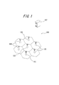
- FIG. 1 is a schematic configuration diagram showing an overview of a communication system according to an embodiment of the present invention.
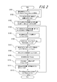
- FIG. 2 is a flowchart showing a method for changing the PCI of the base station apparatus.
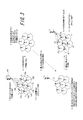
- FIG. 3 is an explanatory diagram illustrating a PCI changing method of the base station apparatus.
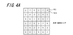
- FIG. 4A is an explanatory diagram illustrating a situation in which a PCI change is necessary.
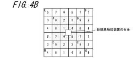
- FIG. 4B is an explanatory diagram illustrating a situation in which the PCI needs to be changed.
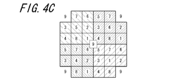
- FIG. 4C is an explanatory diagram illustrating a situation where the PCI needs to be changed.
- FIG. 1 is a schematic configuration diagram showing an overview of a communication system according to an embodiment of the present invention.
- the communication system 101 of the present invention includes a base station device 103, an adjacent base station device 105, and an external control device 107 (a control device having a transmission power control unit in the claims).
- the base station device 103 and the adjacent base station device 105 communicate with a mobile phone terminal (not shown), and are called eNBs in the LTE system.
- a cell indicating an area where the base station apparatus 103 can communicate with the mobile phone terminal (communication area in the claims) is represented by a hexagon surrounding the base station apparatus 103 in FIG.
- the adjacent base station device 105 is a base station device around the base station device 103, and a cell of each adjacent base station device 105 (a range represented by a hexagon surrounding each base station device 105) is the base station device 103. Is adjacent to the cell.
- PCI identification number in the claims
- PCI is assigned to the cell of the base station apparatus 103 and the cell of the adjacent base station apparatus 105, respectively.
- a terminal can identify a base station device and perform communication.
- the base station apparatus 103 has an adjacent base station list indicating which PCI is assigned to the cell of the adjacent base station apparatus 105.
- the adjacent base station apparatus 105 has an adjacent base station list related to PCI of an adjacent base station apparatus (not shown) adjacent to the adjacent base station apparatus 105.
- the external control device 107 manages and controls the entire communication system 101 including the base station device 103 and the adjacent base station device 105.
- EMS Electronic Management System
- NMS Network Management
- the external control device 107 instructs the adjacent base station device 105 to increase the transmission power of the radio wave transmitted to communicate with the terminal, or instructs the base station device 103 to perform PCI. Instructing to stop or start operation due to the change.
- the external control device 107 controls the timing of increasing the transmission power of the adjacent base station device 105 and the timing at which the base station device 103 stops or starts operation, thereby increasing the transmission power before changing the PCI.
- the cell range of the base station apparatus 105 can be expanded. If the expanded cell of the adjacent base station device 105 overlaps the cell of the base station device 103, even if the base station device 103 stops operation due to a PCI change, a hole may be generated in the coverage. Absent.
- FIG. 2 is a flowchart illustrating a PCI changing method of the base station apparatus
- FIG. 3 is an explanatory diagram illustrating a PCI changing method of the base station apparatus.
- the external control device 107 transmits, from the base station device 103 and the adjacent base station device 105 that it manages and controls, the adjacent base station list and the transmission power of the radio waves that each base station device transmits to communicate with the terminal. Performance Measurement (statistical data) including the above information is received (step S101). Step S101 is repeated periodically as long as there is no base station apparatus that requires a PCI change (No in step S102).
- step S102 If there is a base station device that requires a PCI change (Yes in step S102), the external control device 107 starts a PCI change process.
- the external control device 107 determines a base station device that requires PCI change processing and a newly assigned PCI (step S103 and FIG. 3-1).
- the PCI is determined for all the base station apparatuses that require a PCI change, and the order in which the PCI changes are further determined.
- the external control device 107 can change the PCI preferentially from the base station device that is considered to have little influence on the operation service. For example, the size of the transmission power or the terminal communicating with the base station device can be changed. The order can be determined based on information such as numbers.
- the newly allocated PCI is (1) the newly allocated PCI is not the same as the PCI of the cell of the base station apparatus adjacent to the base station apparatus, and (2) the newly allocated PCI is a base station adjacent to the base station apparatus. Further, it is necessary to satisfy two conditions that it is not the same as the PCI of the cell of the base station apparatus adjacent to the apparatus. Assuming that the base station apparatus that needs to change the PCI is the base station apparatus 103, the newly assigned PCI is added to both the adjacent base station list of the base station apparatus 103 and the adjacent base station list of the adjacent base station apparatus 105. If the value does not exist, the above two conditions are satisfied.
- the external control device 107 notifies the new PCI to the base station device 103 whose PCI is to be changed, and instructs pre-blocking (step S104). Pre-blocking is to stop the communication function after waiting for line disconnection without forcibly disconnecting a connected call.
- the external control apparatus 107 increases the transmission power with respect to the adjacent base station apparatus 105 adjacent to the base station apparatus 103 until the cell of the adjacent base station apparatus 105 can cover the cell of the base station apparatus 103.
- An instruction is given (step S105 and FIGS. 3-2 to 7). During this period, the base station apparatus 103 is making a transition to pre-blocking (FIGS. 3-8).
- the adjacent base station device 105 increases the transmission power as described above, so that the coverage in the communication system 101 is maintained even when the base station device 103 stops operating.
- the adjacent base station apparatus 105 can also cover the cell of the base station apparatus 103 using beam forming. Beamforming is a more flexible coverage area by reducing radio wave interference between base station devices by concentrating transmission power in a specific direction (increasing transmission power in a specific direction) by directivity control of radio waves. Is a technology that enables the construction of
- the external control device 107 determines whether or not the increase of the transmission power of the adjacent base station device 105 and the pre-blocking of the base station device 103 have been completed (step S106).
- the base station apparatus 103 After the pre-occlusion is completed (Yes in step S106), the base station apparatus 103 prepares to restart with a new PCI (FIG. 3-10). The base station apparatus 103 changes the PCI to a new PCI, and after the preparation for restart is completed, the base station apparatus 103 notifies the external control apparatus 107 that it can be restarted with the new PCI ( Step S107 and FIG. 3-11).
- the external control device 107 instructs the base station device 103 to restart with a new PCI (step S108 and FIG. 3-11).
- the base station apparatus 103 Upon receiving an instruction to restart with a new PCI, the base station apparatus 103 stops operation and restarts (FIG. 3-12). After the restart, a new PCI is assigned to the cell of the base station apparatus 103, and the base station apparatus 103 notifies the external control apparatus 107 that the PCI change processing has been completed (step S109 and FIG. 3-13). The external control device 107 instructs the base station device 103 to resume operation with a new PCI (step S110), and the base station device 103 can communicate with the terminal again.
- the external control device 107 instructs the adjacent base station device 105 to restore the transmission power (step S111 and FIGS. 3-14 to 19).
- the timing at which the adjacent base station device 105 returns the transmission power to the original is not limited to an instruction from the external control device 107.
- the adjacent base station device 105 restores the transmission power to the original timing when the timer ends. You can also By including the time required for restarting each base station device in Performance Measurement, it is possible to share information on the time required for restart within the communication system 101.
- the external control device 107 determines whether there is any other base station device that requires PCI change among the base station devices in the communication system 101 (step S112). If it exists (No in step S111), the processing from step S104 to step S111 is repeated. If there is no base station apparatus that needs to change the PCI (Yes in step S111), the PCI changing process ends.
- FIGS. 4A to 4C are explanatory diagrams showing a situation in which the PCI needs to be changed.
- FIG. 4A shows a cell arrangement example of the base station apparatus.
- Each of the 36 rectangles shown in FIG. 4A represents a cell of the base station apparatus.
- the number shown in the cell is the PCI assigned to the cell.
- the total number of PCIs that can be used in E-UTRAN in the LTE system is 504.
- the number of usable PCIs is nine.
- a logical area is composed of cells having PCIs 1 to 9 respectively. In FIG. 4A, for example, there are four logical areas surrounded by thick lines.
- the PCI allocated to the new base station apparatus needs to satisfy the above two conditions (1) and (2), but the PCI (1, 4, 5, 6) of the adjacent base station apparatus of the new base station apparatus 1 to 9 have already been assigned to the PCI (2, 3, 7, 8, 9) of the adjacent base station apparatus of the adjacent base station apparatus. Therefore, in order to assign a PCI that satisfies the two conditions (1) and (2) to a new base station apparatus, it is necessary to change the PCI that has already been assigned to another cell.
- the PCI of cells marked A to H in FIG. 4B is changed. Specifically, the PCI of cell A is changed from 9 to 5 and the PCI of cell E is changed from 5 to 9 so that the PCIs of cell A and cell E are interchanged. Similarly, the PCI of cell B and cell F, the PCI of cell C and cell G, and the PCI of cell D and cell H are interchanged, respectively.
- the adjacent base station apparatus of the cell to be changed increases the transmission power before restarting. Thereby, the PCI can be changed without generating a hole in the coverage.
- PCI “9” is assigned to the new base station apparatus.
- the PCI of each cell is as shown in FIG. 4C.
- the logical area is changed, and the four logical areas share the new base station apparatus as shown in FIG. 4C.
- the cells located at the four corners (all PCIs are 9) belong to a logical area different from the four logical areas in FIG. 4C.
- the communication area of the adjacent base station device 105 is different from that of the adjacent base station device 105 when the PCI (identification number) of the base station device 103 is changed.
- 103 has an external control device 107 (control device having a transmission power control unit) that instructs to increase the transmission power of the adjacent base station device 105 before changing the identification number until the communication area 103 is covered. Increases the transmission power of the local station according to the instruction.
- the base station apparatus 103 is restarted in order to change the PCI, the communication area that the base station apparatus 103 was responsible for cannot be communicated.
- the adjacent base station device 105 increases the transmission power before changing the PCI and expands the communication area of the adjacent base station device 105 to the communication area of the base station device 103, thereby restarting the base station device 103. It is possible to prevent the occurrence of an incommunicable area. That is, it is possible to change the PCI without generating a hole in the coverage.
- the base station apparatus 103 stops operation when the PCI of the own station is changed, and the external control apparatus 107 changes the base station apparatus 103 when the PCI of the base station apparatus 103 is changed.
- the adjacent base station device 105 are instructed to resume operation, and instruct the adjacent base station device 105 to restore the transmission power of the adjacent base station 105 to its original state.
- the transmission power of the adjacent base station 105 is restored, so that there is no hole in the coverage and the transmission of the adjacent base station 105 It is possible to avoid consuming more power than necessary.
- each member, each means, each step, etc. can be rearranged so as not to be logically contradictory, and a plurality of means, steps, etc. can be combined into one or divided. Is possible.
- the transmission power control unit according to the claim is configured to control the base station apparatus and the adjacent base station apparatus, and the components of the external control apparatus that are separate from the base station apparatus and the adjacent base station apparatus.
- the base station apparatus that needs to change the PCI transmits information for notifying the adjacent base station apparatus that the PCI is to be changed by inter-base station communication using the X2 interface. Receiving this information, the adjacent base station apparatus increases the transmission power, and when the increase of the transmission power is completed, transmits information indicating that to the base station apparatus. The base station apparatus restarts to change the PCI, resumes operation with a new PCI, and then transmits information for instructing the adjacent base station apparatus to lower the transmission power.
- the external control device has been described as having a function for changing the PCI without generating an incommunicable area.
- the function is realized by exchanging information using a predetermined control channel (transmission power control means).
Landscapes
- Engineering & Computer Science (AREA)
- Computer Networks & Wireless Communication (AREA)
- Signal Processing (AREA)
- Mobile Radio Communication Systems (AREA)
Abstract
カバレッジに穴を発生させることなく、基地局装置のPCIを変更することが可能な通信システム、制御装置及び基地局装置を提供することにある。 本発明に係る通信システム101は、基地局装置103と、当該基地局装置に隣接する隣接基地局装置105とを含む通信システムにおいて、当該通信システムは、基地局装置103の識別番号が変更される場合、隣接基地局装置105に対して、隣接基地局装置105の通信エリアが基地局装置103の通信エリアを覆うまで隣接基地局装置105の送信電力を識別番号の変更前に上げるよう指示する送信電力制御部107を有し、隣接基地局装置105は、送信電力引き上げの指示によって、自局の送信電力を上げるものである。
Description
本出願は、日本国特許出願2010-037763号(2010年2月23日出願)の優先権を主張するものであり、当該出願の開示全体を、ここに参照のために取り込む。
本発明は、通信システム、制御装置及び基地局装置に関し、特に、通信システムにおける基地局装置の識別番号の変更に関連する通信システム、制御装置及び基地局装置に関する。
次世代の世界標準の無線通信方式として、LTE(Long Term Evolution)システムが3GPP(3rd Generation Partnership Project)で標準化されている。3GPP及びMGMN(Next Generation Mobile Networks)は、LTEシステムにおいて、オペレータの運用コスト削減やネットワークの自動最適化などを目的とするSON(Self Organizing Network)を協議している。SONの機能は、設計(Planning)、展開(Development)、最適化(Optimization)、運用(Maintenance)という4つのカテゴリに分類されるものである。SONの機能が、無線パラメータの最適化やネットワークパラメータの最適化、干渉制御、ネイバーセルリストの追加などのネットワークの効率的な運用・構築・計画に採用されることで、ネットワークの安定性の実現に期待が寄せられている。特に、従来オペレータが手作業で行っていた業務の自動化により、自己設定プロセスや自己最適化プロセスが実現されると、ネットワーク運用コストを最小限にすることが可能となる。自己設定プロセスは、新規に基地局装置eNB(evolved Node B)を設置する際に、システム運用のために必要となる基本的なパラメータを自動的に取得して設定するプロセスとして定義されるものである。この自己設定プロセスは、主に基地局装置が運用状態になる前に動作するプロセスとして考えられている。自己最適化プロセスとは、端末UE(User Equipment)や基地局装置からの統計データを基にネットワークの自動調整を実施するプロセスとして定義されるものである。この自己最適化プロセスは、RF装置の起動後に開始し、基地局装置が運用状態であるときに動作するプロセスとして考えられている。自己最適化プロセスの例としては、隣接基地局リストの最適化があげられる。
SONのより具体的な考え方の一つには、基地局装置のセルに、セルの識別番号であるPCI(Physical Cell ID)を自動的に設定することがあげられる。PCIとは、セルに欠くことのできないパラメータであり、端末がセルと同期をとるために必要となる。LTEの仕様であるE-UTRAN(Evolved Universal Terrestrial Radio Access Network)では、固有なPCIの数は504個と限られているため、セルが504個を越えると、異なるセルで同じPCIを割り当てる必要が生じる。しかし、同じPCIを有するセル同士が近い位置に存在すると、セル間で通信の干渉が生じてしまい、通話やハンドオーバが不可能になるおそれがある。そのため、各セルに割り当てられるセルは、(1)セルのPCIは、基地局装置に隣接する基地局装置のセルのPCIと同一でないこと、(2)セルのPCIは、基地局装置に隣接する基地局装置に更に隣接する基地局装置のセルのPCIと同一でないこと、の2つの条件を満たす必要がある。基地局装置は、隣接基地局装置のセルのPCIの情報を、各基地局装置が有する隣接基地局リスト(ネイバーセルリスト)から得ることができる。
現在、新規に基地局装置を設置する際に、基地局装置が自律的に自セルのPCIを選択して自動設定するフレームワークが3GPPで提案されている(例えば、非特許文献1参照)。具体的には、基地局装置は、自セルのPCIを、Centralized PCI assignment algorithm(集中型PCI割り当てアルゴリズム)又はdistributed PCI assignment algorithm(分散型PCI割り当てアルゴリズム)によって選択することになる。Centralized PCI assignment algorithmでは、OAM(Operation Administration and Maintenance)により、固有のPCIが基地局装置へ知らされ、基地局装置はそのPCIを自セルのPCIとして設定する。一方、distributed PCI assignment algorithmでは、OAMにより、使用可能なPCIが羅列されているPCIリストが基地局装置へ知らされる。基地局装置は、そのリストの中から不適切なPCIを取り除き、リスト内の残ったPCIから任意に選択し、自セルのPCIとして設定する。
また、上記のCentralized PCI assignment algorithm又はdistributed PCI assignment algorithmのように、新規基地局装置の起動前にPCIを設定する方法ではなく、新規基地局装置の起動後にPCIを設定する方法も提案されている(例えば、非特許文献2参照)。まず、新規基地局装置が、コンフィグレーションフェーズで504個のPCI候補から、任意に選択した値をtemporary PCIとして選択して起動する。その後、新規基地局装置は、ANR(Automatic Neighbor Relation)機能によって、端末から報告される隣接基地局装置の情報を得て、隣接基地局リストを作成する。新規基地局装置は、更に、隣接基地局装置から、隣接基地局装置が有する隣接基地局リストを取得する。そして、新規基地局装置は、作成した隣接基地局リストと取得した隣接基地局リストとから、上述の2つの条件(1)及び(2)を満足するPCIを再選択する。
3GPP TS 36.300 22.3.5 Framework for PCI Selection
3GPP R3-080376:SON Use Case: Cell Phy ID Automated Configuration
しかし、非特許文献1に記載されているCentralized PCI assignment algorithm又はdistributed PCI assignment algorithmでは、PCI自動設定方法のフレームワークが示されているに過ぎず、上記の条件(1)及び(2)を満たすPCIをどのように見つけ出すかについての詳細なアルゴリズムについては示されていない。そのため、条件(1)及び(2)を満たさないPCIが、新規基地局装置に割り当てられることがあり、この場合、PCIの再設定が必要となる。再設定するためには、基地局装置は再起動して、新たなPCIで無線チャネルを報知する必要がある。非特許文献2に記載の方法でも、Temporary PCIから条件(1)及び(2)を満たすPCIに変更する際に、基地局装置の再起動が必要となる。基地局装置が再起動する間は、リンク断が生じ、カバレッジ(通信エリア)に穴(通信不能エリア)が発生してしまうことになる。そのため、再起動中の基地局装置のセル内に存在する端末の通信エリアは限定されることになる。
また、非特許文献1及び2の方法は、新規に基地局装置を設置する場合のPCIの設定に関するものであり、既に設定されているPCIを変更することまでは考慮されていない。しかし、上記の条件(1)及び(2)を満たすPCIが存在しない場所に新規基地局装置を設置しなければいけない場合は、既存の基地局装置のPCIの変更が必要となる。既存の基地局装置のPCIの変更が必要となるのは、例えば、端末の総数の増加により、基地局装置の数が不足した場合や、高層ビルの建設により、高層ビルの影が原因となり通信不能エリアが発生してしまった場合などである。このようなカバレッジの補完や拡張などのために、基地局装置は、自セルのPCIを自己最適化プロセスとして変更しなければならない場合がある。更に、マルチベンダ基地局装置の配置等が原因で発生する障害を理由に、既存の基地局装置の変更が必要となる場合もある。これらの場合も、基地局装置の再起動が必要となり、カバレッジに穴が発生することになる。
従って、上記のような従来技術の問題点に鑑みてなされた本発明の目的は、カバレッジに穴を発生させることなく、基地局装置のPCIを変更することが可能な通信システム、制御装置及び基地局装置を提供することにある。
上述した諸課題を解決すべく、第1の観点による通信システムは、
基地局装置と、当該基地局装置に隣接する隣接基地局装置とを含む通信システムにおいて、
当該通信システムは、前記基地局装置の識別番号が変更される場合、前記隣接基地局装置に対して、当該隣接基地局装置の通信エリアが前記基地局装置の通信エリアを覆うまで前記隣接基地局装置の送信電力を前記識別番号の変更前に上げるよう指示する送信電力制御部を有し、
前記隣接基地局装置は、前記指示によって、自局の送信電力を上げる
ものである。
基地局装置と、当該基地局装置に隣接する隣接基地局装置とを含む通信システムにおいて、
当該通信システムは、前記基地局装置の識別番号が変更される場合、前記隣接基地局装置に対して、当該隣接基地局装置の通信エリアが前記基地局装置の通信エリアを覆うまで前記隣接基地局装置の送信電力を前記識別番号の変更前に上げるよう指示する送信電力制御部を有し、
前記隣接基地局装置は、前記指示によって、自局の送信電力を上げる
ものである。
また、前記基地局装置は、自局の前記識別番号が変更されると運転を停止し、
前記送信電力制御部は、前記基地局装置の前記識別番号が変更された場合に、前記基地局装置に対して、運転を再開するよう指示し、かつ、前記隣接基地局装置に対して、前記隣接基地局装置の送信電力を元に戻すよう指示する
ことが望ましい。
前記送信電力制御部は、前記基地局装置の前記識別番号が変更された場合に、前記基地局装置に対して、運転を再開するよう指示し、かつ、前記隣接基地局装置に対して、前記隣接基地局装置の送信電力を元に戻すよう指示する
ことが望ましい。
また、前記基地局装置及び前記隣接基地局装置とは異なる制御装置が前記送信電力制御部を有することが望ましい。
また、前記基地局装置及び前記隣接基地局装置の双方、又はいずれか一方が前記送信電力制御部を有することが望ましい。
上述した諸課題を解決すべく、第2の観点による通信システムは、
基地局装置と、当該基地局装置に隣接する隣接基地局装置を含む通信システムにおいて、
当該通信システムは、前記基地局装置の識別番号が変更される場合、前記隣接基地局装置に対して、当該隣接基地局装置の通信エリアが前記基地局装置の通信エリアを覆うまで前記隣接基地局装置の送信電力を前記識別番号の変更前に上げるよう指示する送信電力制御手段を有し、
前記隣接基地局装置は、前記指示によって、自局の送信電力を上げる
ものである。
基地局装置と、当該基地局装置に隣接する隣接基地局装置を含む通信システムにおいて、
当該通信システムは、前記基地局装置の識別番号が変更される場合、前記隣接基地局装置に対して、当該隣接基地局装置の通信エリアが前記基地局装置の通信エリアを覆うまで前記隣接基地局装置の送信電力を前記識別番号の変更前に上げるよう指示する送信電力制御手段を有し、
前記隣接基地局装置は、前記指示によって、自局の送信電力を上げる
ものである。
また、前記基地局装置の前記識別番号が変更される場合には、
前記基地局装置は、自局の前記識別番号が変更されると、運転を停止し、
前記送信電力制御手段は、前記基地局装置の前記識別番号が変更された場合に、前記基地局装置に対して、運転を再開するよう指示し、かつ、前記隣接基地局装置に対して、前記隣接基地局装置の送信電力を元に戻すよう指示する
ことが望ましい。
前記基地局装置は、自局の前記識別番号が変更されると、運転を停止し、
前記送信電力制御手段は、前記基地局装置の前記識別番号が変更された場合に、前記基地局装置に対して、運転を再開するよう指示し、かつ、前記隣接基地局装置に対して、前記隣接基地局装置の送信電力を元に戻すよう指示する
ことが望ましい。
上述した諸課題を解決すべく、第3の観点による制御装置は、
基地局装置と当該基地局装置に隣接する隣接基地局装置とを制御する制御装置において、
前記基地局装置の識別番号が変更される場合、前記隣接基地局装置に対して、当該隣接基地局装置の通信エリアが前記基地局装置の通信エリアを覆うまで前記隣接基地局装置の送信電力を前記識別番号の変更前に上げるよう指示する
ものである。
基地局装置と当該基地局装置に隣接する隣接基地局装置とを制御する制御装置において、
前記基地局装置の識別番号が変更される場合、前記隣接基地局装置に対して、当該隣接基地局装置の通信エリアが前記基地局装置の通信エリアを覆うまで前記隣接基地局装置の送信電力を前記識別番号の変更前に上げるよう指示する
ものである。
また、前記制御装置は、前記基地局装置の識別番号が変更され、前記基地局装置が運転を停止すると、
前記基地局装置に対して、運転を再開するよう指示し、かつ、前記隣接基地局装置に対して、前記隣接基地局装置の送信電力を元に戻すよう指示する
ことが望ましい。
前記基地局装置に対して、運転を再開するよう指示し、かつ、前記隣接基地局装置に対して、前記隣接基地局装置の送信電力を元に戻すよう指示する
ことが望ましい。
上述した諸課題を解決すべく、第4の観点による基地局装置は、
通信システムにおける基地局装置であって、
自局の識別番号が変更される場合、自局に隣接する隣接基地局装置に対して、当該隣接基地局装置の通信エリアが自局の通信エリアを覆うまで前記隣接基地局装置の送信電力を前記識別番号の変更前に上げるよう指示する送信電力制御部を有する基地局装置である。
通信システムにおける基地局装置であって、
自局の識別番号が変更される場合、自局に隣接する隣接基地局装置に対して、当該隣接基地局装置の通信エリアが自局の通信エリアを覆うまで前記隣接基地局装置の送信電力を前記識別番号の変更前に上げるよう指示する送信電力制御部を有する基地局装置である。
上記のように構成された本発明にかかる通信システム、制御装置及び基地局装置によれば、基地局装置の識別番号の変更前に、送信電力制御部又は送信電力手段によって、隣接基地局装置の送信電力が、隣接基地局装置の通信エリアが基地局装置の通信エリアを覆うまで上がるので、カバレッジに穴を発生させることなく識別番号を変更することが可能である。
以下、本発明の実施の形態について、図面を参照して説明する。
図1は、本発明の一実施形態に係る通信システムの全体像を示す概略構成図である。本発明の通信システム101は、基地局装置103と、隣接基地局装置105と、外部制御装置107(請求項における送信電力制御部を有する制御装置)とを有する。
基地局装置103及び隣接基地局装置105は、携帯電話端末(図示せず)と通信を行うもので、LTEシステムでは、eNBと称される。基地局装置103が携帯電話端末と通信できるエリア(請求項における通信エリア)を示すセルは、図1では基地局装置103を囲む六角形で表されている。隣接基地局装置105は、基地局装置103の周囲の基地局装置であり、各隣接基地局装置105のセル(各基地局装置105を囲む六角形で表される範囲)は、基地局装置103のセルに隣接している。基地局装置103のセル及び隣接基地局装置105のセルには、それぞれPCI(請求項における識別番号)が割り当てられている。このPCIにより、端末は、基地局装置を特定し、通信を行うことができる。基地局装置103は、隣接基地局装置105のセルにどのPCIが割り当てられているかを示す隣接基地局リストを有している。隣接基地局装置105は、当該隣接基地局装置105に隣接する隣接基地局装置(図示せず)のPCIに関する隣接基地局リストを有している。
外部制御装置107は、基地局装置103及び隣接基地局装置105から構成される通信システム101全体を管理及び制御するものであり、例えば、EMS(Element Management System:エレメント管理システム)やNMS(Network Management System:ネットワーク管理システム)である。より詳細には、外部制御装置107は、隣接基地局装置105に対して、端末と通信を行うために送信する電波の送信電力を上げるよう指示したり、基地局装置103に対して、PCIの変更に伴う運転の停止又は開始を指示したりする。外部制御装置107は、隣接基地局装置105の送信電力を上げるタイミングや、基地局装置103が運転を停止又は開始するタイミングを制御することにより、PCIの変更前に、送信電力の引き上げによって、隣接基地局装置105のセルの範囲を拡大させることができる。隣接基地局装置105の拡大されたセルが、基地局装置103のセルに重なっていれば、基地局装置103がPCIの変更のために運転を停止したとしても、カバレッジに穴が発生することがない。
図1の基地局装置103及び隣接基地局装置105が起動している状況で、通信システム101が、基地局装置103のPCIを変更する方法について、図2及び図3を参照して説明する。図2は、基地局装置のPCIの変更方法を示すフローチャートであり、図3は、基地局装置のPCIの変更方法を示す説明図である。
外部制御装置107は、管理及び制御している基地局装置103及び隣接基地局装置105から、それぞれの隣接基地局リストと、各基地局装置が端末と通信を行うために送信する電波の送信電力の情報を含むPerformance Measurement(統計データ)とを受信する(ステップS101)。ステップS101は、PCIの変更が必要な基地局装置が存在しない間は(ステップS102No)、定期的に繰り返される。
PCIの変更が必要な基地局装置が存在すると(ステップS102Yes)、外部制御装置107は、PCIの変更処理を開始する。
外部制御装置107は、PCIの変更処理が必要な基地局装置及び新たに割り当てるPCIを決定する(ステップS103及び図3-1)。PCIの変更が必要な基地局装置が複数存在する場合は、PCIの変更が必要な基地局装置全てに対してPCIを決定して、更にPCIの変更を行う順番についても決定しておく。外部制御装置107は、運用サービスへの影響が少ないと思われる基地局装置から優先的にPCIを変更させることができ、例えば、送信電力の大きさや、基地局装置と通信を行っている端末の数などの情報を基に順番を決定することができる。新たに割り当てるPCIは、(1)新たに割り当てるPCIは、基地局装置に隣接する基地局装置のセルのPCIと同一でないこと、(2)新たに割り当てるPCIは、基地局装置に隣接する基地局装置に更に隣接する基地局装置のセルのPCIと同一でないこと、という2つの条件を満足する必要がある。PCIの変更が必要な基地局装置が基地局装置103であるとすると、新たに割り当てるPCIは、基地局装置103が有する隣接基地局リスト及び隣接基地局装置105が有する隣接基地局リストの双方に存在しない値であれば、上記の2つの条件を満たすことになる。
外部制御装置107は、PCIが変更される基地局装置103に新たなPCIを通知し、予閉塞を指示する(ステップS104)。予閉塞とは、接続中の呼については強制切断せずに、回線切断を待ってから通信機能を停止させることである。
続いて、外部制御装置107は、基地局装置103に隣接する隣接基地局装置105に対して、隣接基地局装置105のセルが基地局装置103のセルを覆うことができるまで送信電力を上げるよう指示する(ステップS105及び図3-2~7)。この間、基地局装置103では、予閉塞への移行が進んでいる(図3-8)。
隣接基地局装置105が、上述のように送信電力を上げることにより、基地局装置103が運転を停止しても、通信システム101におけるカバレッジが維持されることになる。なお、隣接基地局装置105は、ビームフォーミングを用いて基地局装置103のセルを覆うこともできる。ビームフォーミングとは、電波の指向性制御により特定の方向に送信電力を集中させる(特定の方向への送信電力を上げる)ことで、各基地局装置間の電波干渉を減らし、より柔軟なカバレッジエリアの構築を可能にする技術である。
図3-9に示されるように、外部制御装置107は、隣接基地局装置105の送信電力の引き上げ及び基地局装置103の予閉塞が完了したか否かを判断する(ステップS106)。
予閉塞が完了した後(ステップS106のYes)、基地局装置103は、新たなPCIで再起動するための準備を行う(図3-10)。基地局装置103は、PCIを新たなPCIに変更し、再起動の準備完了後、基地局装置103は、外部制御装置107に新たなPCIで再起動が可能な状態であることを通知する(ステップS107及び図3-11)。
外部制御装置107は、通知を受け取ると、基地局装置103に、新たなPCIで再起動するよう指示する(ステップS108及び図3-11)。
基地局装置103は、新たなPCIで再起動するよう指示を受けると、運転を停止し、再起動する(図3-12)。再起動後、新たなPCIが基地局装置103のセルに割り当てられ、基地局装置103は、PCIの変更処理が完了したことを外部制御装置107に通知する(ステップS109及び図3-13)。外部制御装置107は、基地局装置103に新たなPCIで運転を再開するよう指示し(ステップS110)、基地局装置103は、再び端末と通信することが可能となる。
外部制御装置107は、隣接基地局装置105に送信電力を元に戻すよう指示する(ステップS111及び図3-14~19)。なお、隣接基地局装置105が送信電力を元に戻すタイミングは、外部制御装置107からの指示に限定されるわけではない。例えば、隣接基地局装置105が、タイマーを有し、再起動にかかる時間以上の時間がタイマーに設定されている場合は、隣接基地局装置105はタイマーが終了したタイミングで送信電力を元に戻すこともできる。各基地局装置の再起動にかかる時間を、Performance Measurementに含ませることにより、通信システム101内で、再起動にかかる時間の情報を共有することができる。
外部制御装置107は、通信システム101内の基地局装置のなかで、PCIの変更が必要な基地局装置が他に存在しないか判断する(ステップS112)。存在する場合は(ステップS111のNo)、ステップS104~ステップS111までの処理が繰り返される。PCIの変更が必要な基地局装置が存在しない場合は(ステップS111のYes)、PCIの変更処理が終了する。
上記実施形態では、カバレッジに穴を発生させることなく、基地局装置のPCIを変更する方法について説明してきた。続いて、どのような状況でPCIの変更が必要になるかについて図4A~Cを用いて説明する。図4A~Cは、PCIの変更が必要となる状況を示す説明図である。
図4Aには、基地局装置のセルの配置例が記載されている。図4Aに示されている36個の四角形がそれぞれ、基地局装置のセルを表している。セルごとに基地局装置が存在する。セル内に示されている数字は、セルに割り当てられたPCIである。LTEシステムのE-UTRANで使用できるPCIの総数は504個であるが、ここでは、説明の便宜上、使用可能なPCIの数は9個であるとする。1~9までのPCIをそれぞれ有するセルで論理エリアを構成し、図4Aには、例えば、太線で囲まれた4つの論理エリアが存在することになる。
通話品質の安定等を目的として、図4Bのように、中央に新たな基地局を建設する必要が生じたとする。新規基地局装置に割り当てられるPCIは、上記の(1)及び(2)の2つの条件を満たす必要があるが、新規基地局装置の隣接基地局装置のPCI(1、4、5、6)と隣接基地局装置の更なる隣接基地局装置のPCI(2、3、7、8、9)とに既に1~9が割り当てられている。そのため、新規基地局装置に(1)及び(2)の2つの条件を満たすPCIを割り当てるためには、既に他のセルに割り当てられているPCIを変更する必要がある。
ここで、一例として、図4BのA~Hが付されたセルのPCIを変更することにする。具体的には、セルAとセルEとのPCIが入れ替わるように、セルAのPCIを9から5に変更し、セルEのPCIを5から9に変更する。同様にして、セルBとセルFとのPCIを、セルCとセルGとのPCIを、セルDとセルHとのPCIをそれぞれ入れ替える。A~Hの各セルのPCIを変更する際には、再起動前に、変更するセルの隣接基地局装置は送信電力を上げておく。これにより、カバレッジに穴を発生させることなくPCIの変更が可能となる。A~Hの各セルのPCIの変更後、新規基地局装置にPCI「9」を割り当てる。よって、各セルのPCIは図4Cのようになる。新規基地局装置の設置に伴い、論理エリアは変更され、図4Cのように4つの論理エリアが新規基地局装置を共有する形となっている。四隅に位置するセル(全てPCIは9)は、図4Cの4つの論理エリアとは異なる論理エリアに属することになる。以上のように、新規基地局装置にPCIを割り当てる際に、(1)及び(2)の条件を満たすPCIが存在しない場合には、既存の基地局装置のPCIの変更が必要になる。
このように本実施形態では、通信システム101は、基地局装置103のPCI(識別番号)が変更される場合、隣接基地局装置105に対して、隣接基地局装置105の通信エリアが基地局装置103の通信エリアを覆うまで隣接基地局装置105の送信電力を前記識別番号の変更前に上げるよう指示する外部制御装置107(送信電力制御部を有する制御装置)を有し、隣接基地局装置105は、当該指示によって自局の送信電力を上げる。PCIを変更するために、基地局装置103が再起動すると、基地局装置103が受け持っていた通信エリアは、通信不可能になる。しかし、隣接基地局装置105がPCIの変更前に送信電力を上げ、隣接基地局装置105の通信エリアを基地局装置103の通信エリアまで拡大しておくことにより、基地局装置103の再起動に伴う通信不能エリアの発生を防ぐことができる。つまり、カバレッジに穴を発生させることなく、PCIの変更を行うことが可能である。
また、本実施形態では、基地局装置103は、自局のPCIが変更されると運転を停止し、外部制御装置107は、基地局装置103のPCIが変更された場合に、基地局装置103に対して、運転を再開するよう指示し、かつ、隣接基地局装置105に対して、隣接基地局105の送信電力を元に戻すよう指示する。基地局装置103のPCIが変更され、基地局装置103の運転が再開された後に、隣接基地局105の送信電力が元に戻るので、カバレッジに穴が空くことなく、また隣接基地局105の送信電力を必要以上に消費することが避けられる。
本発明を諸図面や実施例に基づき説明してきたが、当業者であれば本開示に基づき種々の変形や修正を行うことが容易であることに注意されたい。従って、これらの変形や修正は本発明の範囲に含まれることに留意されたい。例えば、各部材、各手段、各ステップ等に含まれる機能等は論理的に矛盾しないように再配置可能であり、複数の手段やステップ等を1つに組み合わせたり、或いは分割したりすることが可能である。
上述した本発明の実施形態の説明では、基地局装置及び隣接基地局装置を制御する請求項記載の送信電力制御部を、基地局装置及び隣接基地局装置とは別個の外部制御装置の構成要素であるとして説明したが、送信電力制御部を基地局装置及び隣接基地局装置の双方、又はいずれか一方の内部に設けて、本発明を実現することもできる。この場合、PCIの変更が必要な基地局装置は、X2インターフェースを用いた基地局間通信により隣接基地局装置にPCIを変更する旨を通知するための情報を送信する。この情報を受けた隣接基地局装置は、それぞれ送信電力を上げ、送信電力の引き上げが完了すると、その旨を示す情報を基地局装置に送信する。基地局装置は、PCI変更のための再起動を行い、新たなPCIで運転を再開した後、隣接基地局装置に送信電力の引き下げを指示するための情報を送信する。
また、上述した本発明の実施形態の説明では、外部制御装置(送信電力制御部)が、通信不能エリアを発生させることなくPCIを変更するための機能を備えているものとして記載したが、かかる機能は、所定の制御チャネル(送信電力制御手段)を用いた情報のやりとりにより実現される。
101 通信システム
103 基地局装置
105 隣接基地局装置
107 外部制御装置
103 基地局装置
105 隣接基地局装置
107 外部制御装置
Claims (9)
- 基地局装置と、当該基地局装置に隣接する隣接基地局装置とを含む通信システムにおいて、
当該通信システムは、前記基地局装置の識別番号が変更される場合、前記隣接基地局装置に対して、当該隣接基地局装置の通信エリアが前記基地局装置の通信エリアを覆うまで前記隣接基地局装置の送信電力を前記識別番号の変更前に上げるよう指示する送信電力制御部を有し、
前記隣接基地局装置は、前記指示によって、自局の送信電力を上げる
通信システム。 - 請求項1に記載の通信システムにおいて、
前記基地局装置は、自局の前記識別番号が変更されると運転を停止し、
前記送信電力制御部は、前記基地局装置の前記識別番号が変更された場合に、前記基地局装置に対して、運転を再開するよう指示し、かつ、前記隣接基地局装置に対して、前記隣接基地局装置の送信電力を元に戻すよう指示する
ことを特徴とする通信システム。 - 請求項1に記載の通信システムにおいて、前記基地局装置及び前記隣接基地局装置とは異なる制御装置が前記送信電力制御部を有することを特徴する通信システム。
- 請求項1に記載の通信システムにおいて、前記基地局装置及び前記隣接基地局装置の双方、又はいずれか一方が前記送信電力制御部を有することを特徴とする通信システム。
- 基地局装置と、当該基地局装置に隣接する隣接基地局装置を含む通信システムにおいて、
当該通信システムは、前記基地局装置の識別番号が変更される場合、前記隣接基地局装置に対して、当該隣接基地局装置の通信エリアが前記基地局装置の通信エリアを覆うまで前記隣接基地局装置の送信電力を前記識別番号の変更前に上げるよう指示する送信電力制御手段を有し、
前記隣接基地局装置は、前記指示によって、自局の送信電力を上げる
通信システム。 - 請求項5に記載の通信システムにおいて、
前記基地局装置は、自局の前記識別番号が変更されると、運転を停止し、
前記送信電力制御手段は、前記基地局装置の前記識別番号が変更された場合に、前記基地局装置に対して、運転を再開するよう指示し、かつ、前記隣接基地局装置に対して、前記隣接基地局装置の送信電力を元に戻すよう指示する
ことを特徴とする通信システム。 - 基地局装置と当該基地局装置に隣接する隣接基地局装置とを制御する制御装置において、
前記基地局装置の識別番号が変更される場合、前記隣接基地局装置に対して、当該隣接基地局装置の通信エリアが前記基地局装置の通信エリアを覆うまで前記隣接基地局装置の送信電力を前記識別番号の変更前に上げるよう指示する
制御装置。 - 請求項7に記載の制御装置において、前記基地局装置の識別番号が変更され、前記基地局装置が運転を停止すると、
前記基地局装置に対して、運転を再開するよう指示し、かつ、前記隣接基地局装置に対して、前記隣接基地局装置の送信電力を元に戻すよう指示する
ことを特徴とする制御装置。 - 通信システムにおける基地局装置であって、
自局の識別番号が変更される場合、自局に隣接する隣接基地局装置に対して、当該隣接基地局装置の通信エリアが自局の通信エリアを覆うまで前記隣接基地局装置の送信電力を前記識別番号の変更前に上げるよう指示する送信電力制御部を有する基地局装置。
Priority Applications (1)
| Application Number | Priority Date | Filing Date | Title |
|---|---|---|---|
| US13/580,871 US8923911B2 (en) | 2010-02-23 | 2011-02-22 | Communication system, control apparatus and base station apparatus |
Applications Claiming Priority (2)
| Application Number | Priority Date | Filing Date | Title |
|---|---|---|---|
| JP2010-037763 | 2010-02-23 | ||
| JP2010037763A JP5523867B2 (ja) | 2010-02-23 | 2010-02-23 | 通信システム、制御装置及び基地局装置 |
Publications (1)
| Publication Number | Publication Date |
|---|---|
| WO2011105052A1 true WO2011105052A1 (ja) | 2011-09-01 |
Family
ID=44506484
Family Applications (1)
| Application Number | Title | Priority Date | Filing Date |
|---|---|---|---|
| PCT/JP2011/000987 Ceased WO2011105052A1 (ja) | 2010-02-23 | 2011-02-22 | 通信システム、制御装置及び基地局装置 |
Country Status (3)
| Country | Link |
|---|---|
| US (1) | US8923911B2 (ja) |
| JP (1) | JP5523867B2 (ja) |
| WO (1) | WO2011105052A1 (ja) |
Cited By (2)
| Publication number | Priority date | Publication date | Assignee | Title |
|---|---|---|---|---|
| CN102421101A (zh) * | 2011-12-31 | 2012-04-18 | 北京邮电大学 | 一种物理小区标识的自配置方法 |
| EP2749104A4 (en) * | 2012-04-17 | 2015-07-08 | Ericsson Telefon Ab L M | INTERFERENCE SUPPRESSION IN A WIRELESS COMMUNICATION NETWORK |
Families Citing this family (7)
| Publication number | Priority date | Publication date | Assignee | Title |
|---|---|---|---|---|
| CN103748553B (zh) * | 2011-06-28 | 2018-09-21 | 惠普发展公司,有限责任合伙企业 | 客户端的操作状态信息在远程桌面会话中的显示 |
| WO2013077059A1 (ja) * | 2011-11-25 | 2013-05-30 | 日本電気株式会社 | セル識別子割当方法、基地局、保守サーバ、移動通信システム |
| JP2013255183A (ja) * | 2012-06-08 | 2013-12-19 | Toshiba Corp | 無線管理装置、無線通信システム、及び無線通信制御方法 |
| US9992699B2 (en) | 2013-06-17 | 2018-06-05 | Nec Corporation | Son control system, son control method, and mobile communication system |
| WO2015038230A1 (en) * | 2013-09-13 | 2015-03-19 | Eden Rock Communications, Llc | Method and system for automatic neighbor relations in multi-vendor heterogeneous network |
| CN107852704A (zh) * | 2015-07-17 | 2018-03-27 | 华为技术有限公司 | 配置信息获取的方法和装置 |
| EP3488629B1 (en) * | 2016-07-25 | 2023-06-28 | Nokia Solutions and Networks Oy | Pci allocation in lte-u |
Citations (3)
| Publication number | Priority date | Publication date | Assignee | Title |
|---|---|---|---|---|
| JPH07170566A (ja) * | 1993-12-16 | 1995-07-04 | Nec Corp | 無線電話システムの通信制御方式 |
| JP2005010821A (ja) * | 2003-04-22 | 2005-01-13 | Hitachi Communication Technologies Ltd | 無線通信装置及び無線通信網 |
| JP2007116391A (ja) * | 2005-10-20 | 2007-05-10 | Ntt Docomo Inc | 基地局装置、無線通信用パラメータ設定方法 |
Family Cites Families (5)
| Publication number | Priority date | Publication date | Assignee | Title |
|---|---|---|---|---|
| US8559952B2 (en) * | 2007-08-14 | 2013-10-15 | Telefonaktiebolaget Lm Ericsson (Publ) | Automated and seamless change of reporting cell identity |
| US8599750B2 (en) | 2008-01-31 | 2013-12-03 | Sharp Kabushiki Kaisha | Base station device, mobile station device, communication system, communication method, and communication program |
| US8391158B2 (en) * | 2008-07-25 | 2013-03-05 | Qualcomm Incorporated | Cell identifier assignment and selection |
| EP2154917A1 (en) * | 2008-08-13 | 2010-02-17 | Nokia Siemens Networks OY | Transmission of a synchronization signal within a cellular telecommunication network with temporarily increased transmitting power |
| US9392627B2 (en) * | 2012-09-13 | 2016-07-12 | Qualcomm Incorporated | Method and apparatus for physical cell identifier collision detection and neighboring cell list construction |
-
2010
- 2010-02-23 JP JP2010037763A patent/JP5523867B2/ja not_active Expired - Fee Related
-
2011
- 2011-02-22 WO PCT/JP2011/000987 patent/WO2011105052A1/ja not_active Ceased
- 2011-02-22 US US13/580,871 patent/US8923911B2/en not_active Expired - Fee Related
Patent Citations (3)
| Publication number | Priority date | Publication date | Assignee | Title |
|---|---|---|---|---|
| JPH07170566A (ja) * | 1993-12-16 | 1995-07-04 | Nec Corp | 無線電話システムの通信制御方式 |
| JP2005010821A (ja) * | 2003-04-22 | 2005-01-13 | Hitachi Communication Technologies Ltd | 無線通信装置及び無線通信網 |
| JP2007116391A (ja) * | 2005-10-20 | 2007-05-10 | Ntt Docomo Inc | 基地局装置、無線通信用パラメータ設定方法 |
Cited By (3)
| Publication number | Priority date | Publication date | Assignee | Title |
|---|---|---|---|---|
| CN102421101A (zh) * | 2011-12-31 | 2012-04-18 | 北京邮电大学 | 一种物理小区标识的自配置方法 |
| EP2749104A4 (en) * | 2012-04-17 | 2015-07-08 | Ericsson Telefon Ab L M | INTERFERENCE SUPPRESSION IN A WIRELESS COMMUNICATION NETWORK |
| US9294979B2 (en) | 2012-04-17 | 2016-03-22 | Telefonaktiebolaget L M Ericsson (Publ) | Interference suppression in a wireless communication network |
Also Published As
| Publication number | Publication date |
|---|---|
| JP2011176471A (ja) | 2011-09-08 |
| US8923911B2 (en) | 2014-12-30 |
| JP5523867B2 (ja) | 2014-06-18 |
| US20120322436A1 (en) | 2012-12-20 |
Similar Documents
| Publication | Publication Date | Title |
|---|---|---|
| JP5523867B2 (ja) | 通信システム、制御装置及び基地局装置 | |
| US11089567B2 (en) | Communication system, base station, host node, and communication method | |
| US10231284B2 (en) | Telecommunication system | |
| CN101557654B (zh) | 网络覆盖优化处理方法和系统 | |
| US8897838B2 (en) | Communication system | |
| US20120257544A1 (en) | Configuration space feedback and optimization in a self-configuring communication system | |
| JP6190960B2 (ja) | 補償セルの利用可能なキャパシティに基づく通信システム無線カバレッジ再構成 | |
| CN111869270A (zh) | 管理非协调无线电接入网络 | |
| US20110223920A1 (en) | Wireless communication system and method for assigning physical-layer cell identities of base stations in wireless communication system | |
| CN111869254A (zh) | 管理非协调无线电接入网络 | |
| JP6551509B2 (ja) | 無線基地局、コアネットワーク装置、無線通信システム、無線通信方法 | |
| EP2107838A1 (en) | Method for configuring a base station and base station in a wireless communication network | |
| KR20110023726A (ko) | 무선통신 시스템에서 펨토 기지국의 서비스 상태 정보 전송방법 | |
| JP2013110533A (ja) | 基地局、無線通信システム及び障害発生通知方法 | |
| Sanneck et al. | Context based configuration management of plug & play LTE base stations | |
| JP2012009990A (ja) | 無線通信システム |
Legal Events
| Date | Code | Title | Description |
|---|---|---|---|
| 121 | Ep: the epo has been informed by wipo that ep was designated in this application |
Ref document number: 11747023 Country of ref document: EP Kind code of ref document: A1 |
|
| NENP | Non-entry into the national phase |
Ref country code: DE |
|
| WWE | Wipo information: entry into national phase |
Ref document number: 13580871 Country of ref document: US |
|
| 122 | Ep: pct application non-entry in european phase |
Ref document number: 11747023 Country of ref document: EP Kind code of ref document: A1 |